EP2249920B1 - Lead with mri compatible design features - Google Patents
Lead with mri compatible design featuresDownload PDFInfo
- Publication number
- EP2249920B1 EP2249920B1EP09707389.4AEP09707389AEP2249920B1EP 2249920 B1EP2249920 B1EP 2249920B1EP 09707389 AEP09707389 AEP 09707389AEP 2249920 B1EP2249920 B1EP 2249920B1
- Authority
- EP
- European Patent Office
- Prior art keywords
- lead
- wire
- conductor wire
- electrode conductor
- inner electrode
- Prior art date
- Legal status (The legal status is an assumption and is not a legal conclusion. Google has not performed a legal analysis and makes no representation as to the accuracy of the status listed.)
- Not-in-force
Links
- 239000004020conductorSubstances0.000claimsdescription76
- 238000002595magnetic resonance imagingMethods0.000claimsdescription23
- BQCADISMDOOEFD-UHFFFAOYSA-NSilverChemical compound[Ag]BQCADISMDOOEFD-UHFFFAOYSA-N0.000claimsdescription15
- 229910052709silverInorganic materials0.000claimsdescription15
- 239000004332silverSubstances0.000claimsdescription15
- 238000000034methodMethods0.000claimsdescription12
- 239000000463materialSubstances0.000claimsdescription9
- 238000009413insulationMethods0.000claimsdescription6
- 238000010276constructionMethods0.000description11
- 230000000747cardiac effectEffects0.000description4
- 230000005684electric fieldEffects0.000description4
- 238000012986modificationMethods0.000description4
- 230000004048modificationEffects0.000description4
- 230000001225therapeutic effectEffects0.000description4
- 230000005670electromagnetic radiationEffects0.000description3
- 238000010438heat treatmentMethods0.000description3
- 238000003384imaging methodMethods0.000description3
- 208000001871TachycardiaDiseases0.000description2
- 206010003119arrhythmiaDiseases0.000description2
- 208000006218bradycardiaDiseases0.000description2
- 230000036471bradycardiaEffects0.000description2
- 230000008878couplingEffects0.000description2
- 238000010168coupling processMethods0.000description2
- 238000005859coupling reactionMethods0.000description2
- 230000003247decreasing effectEffects0.000description2
- 238000002513implantationMethods0.000description2
- 229910052751metalInorganic materials0.000description2
- 239000002184metalSubstances0.000description2
- 229910001092metal group alloyInorganic materials0.000description2
- 210000005245right atriumAnatomy0.000description2
- 210000005241right ventricleAnatomy0.000description2
- 230000006794tachycardiaEffects0.000description2
- 238000002560therapeutic procedureMethods0.000description2
- 238000011282treatmentMethods0.000description2
- 238000005481NMR spectroscopyMethods0.000description1
- 210000001015abdomenAnatomy0.000description1
- 238000007792additionMethods0.000description1
- 230000006793arrhythmiaEffects0.000description1
- 238000007796conventional methodMethods0.000description1
- 230000000694effectsEffects0.000description1
- 230000005672electromagnetic fieldEffects0.000description1
- 230000010354integrationEffects0.000description1
- 210000005246left atriumAnatomy0.000description1
- 210000005240left ventricleAnatomy0.000description1
- 238000004519manufacturing processMethods0.000description1
- 208000010125myocardial infarctionDiseases0.000description1
- 230000001537neural effectEffects0.000description1
- 230000000926neurological effectEffects0.000description1
- 229920002635polyurethanePolymers0.000description1
- 239000004814polyurethaneSubstances0.000description1
- 230000009467reductionEffects0.000description1
- 230000004044responseEffects0.000description1
- 229910052710siliconInorganic materials0.000description1
- 239000010703siliconSubstances0.000description1
- 210000003462veinAnatomy0.000description1
- 238000004804windingMethods0.000description1
Images

Classifications
- A—HUMAN NECESSITIES
- A61—MEDICAL OR VETERINARY SCIENCE; HYGIENE
- A61N—ELECTROTHERAPY; MAGNETOTHERAPY; RADIATION THERAPY; ULTRASOUND THERAPY
- A61N1/00—Electrotherapy; Circuits therefor
- A61N1/02—Details
- A61N1/04—Electrodes
- A61N1/05—Electrodes for implantation or insertion into the body, e.g. heart electrode
- A61N1/056—Transvascular endocardial electrode systems
- A—HUMAN NECESSITIES
- A61—MEDICAL OR VETERINARY SCIENCE; HYGIENE
- A61N—ELECTROTHERAPY; MAGNETOTHERAPY; RADIATION THERAPY; ULTRASOUND THERAPY
- A61N1/00—Electrotherapy; Circuits therefor
- A61N1/02—Details
- A61N1/08—Arrangements or circuits for monitoring, protecting, controlling or indicating
- A61N1/086—Magnetic resonance imaging [MRI] compatible leads
Definitions
- the present inventionrelates to medical devices and the simultaneous delivery of diagnostic and therapeutic treatments. More specifically, the present invention relates to implantable medical leads with magnetic shielding and methods of shielding such leads from magnetic fields during medical procedures such as magnetic resonance imaging (MRI).
- MRImagnetic resonance imaging
- Magnetic resonance imagingis a non-invasive imaging method that utilizes nuclear magnetic resonance techniques to render images within a patient's body.
- MRI systemsemploy the use of a magnetic coil having a magnetic field strength of between about 0.2 to 3 Teslas.
- the body tissueis briefly exposed to RF pulses of electromagnetic energy in a plane perpendicular to the magnetic field. The resultant electromagnetic energy from these pulses can be used to image the body tissue by measuring the relaxation properties of the excited atomic nuclei in the tissue.
- the electromagnetic radiation produced by the MRI systemmay be picked up by implantable device leads used in implantable medical devices such as pacemakers or cardiac defibrillators.
- This energymay be transferred through the lead to the electrode in contact with the tissue, which may lead to elevated temperatures at the point of contact.
- the degree of tissue heatingis typically related to factors such as the length of the lead, the conductivity or impedance of the lead, and the surface area of the lead electrodes. Exposure to a magnetic field may also induce an undesired voltage on the lead.
- the present inventionrelates to implantable medical leads with magnetic shielding and methods of shielding implantable leads from magnetic fields during medical procedures such as magnetic resonance imaging (MRI).
- An illustrative medical deviceincludes a pulse generator and a lead having a helically coiled inner electrode conductor wire, a helically coiled outer electrode conductor wire, and one or more insulation layers.
- the inner electrode conductor wirehas a hollowed, multifilar configuration including six or more co-radially wound wire filars.
- the outer electrode conductor wireis electrically isolated from the inner electrode conductor wire, and has either a single filar or double filar configuration with a relatively high inductance that is adapted to dissipate electromagnetic energy received by the lead during a magnetic resonance procedure.
- FIG. 1is a schematic view of an illustrative medical device 12 having with a lead implanted within the body of a patient.
- the medical device 12comprises a pulse generator implanted within the body.
- the pulse generator 12is coupled to a lead 14 inserted into the patient's heart 16.
- the heart 16includes a right atrium 18, a right ventricle 20, a left atrium 22, and a left ventricle 24.
- the pulse generator 12can be implanted subcutaneously within the body, typically at a location such as in the patient's chest or abdomen, although other implantation locations are possible.
- a proximal section 26 of the lead 14can be coupled to or formed integrally with the pulse generator 12.
- a distal section 28 of the lead 14, in turn,can be implanted at a desired location in or near the heart 16 such as in the right ventricle 20, as shown.
- one or more electrodes 30 on the distal section 28 of the lead 14may provide therapy to the patient in the form of an electrical current to the heart 16.
- the electrode(s) 30may be provided as part of a cardiac lead 14 used to treat bradycardia, tachycardia, or other cardiac arrhythmias.
- the illustrative embodimentdepicts only a single lead 14 inserted into the patient's heart 16, in other embodiments multiple leads can be utilized so as to electrically stimulate other areas of the heart. 16.
- the distal section of a second leadmay be implanted in the right atrium 18.
- another leadmay be implanted in or near the left side of the heart 16 (e.g., in the coronary veins) to stimulate the left side of the heart 16.
- Other types of leadssuch as epicardial leads may also be utilized in addition to, or in lieu of, the lead 14 depicted in Figure 1 .
- the lead 14can be configured to convey electrical signals between the pulse generator 12 and the heart 16.
- the lead 14can be utilized to deliver electrical therapeutic stimulus for pacing the heart 16.
- the pulse generator 12can be utilized to deliver electrical stimulus in the form of pacing pulses to the heart 16.
- the pulse generator 12is an implantable cardiac defibrillator
- the lead 14can be utilized to delver electric shocks to the heart 16 in response to an event such as a heart attack or arrhythmia.
- the pulse generator 12includes both pacing and defibrillation capabilities.
- electromagnetic radiationis produced within the body that can be picked up by the lead 14 and transferred to the lead electrode(s) 30 in contact with the body tissue. This electromagnetic radiation can cause heating at the interface of the lead electrode(s) 30 and body tissue, and can interfere with the therapeutic electrical currents transmitted by the pulse generator 12 through the lead 14.
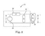
- FIG 2is a schematic view showing a simplified equivalence circuit 32 for the lead 14 of Figure 1 , representing the RF energy picked up on the lead 14 from RF electromagnetic energy produced by an MRI scanner.
- Vi 34 in the circuit 32represents an equivalent source of energy picked up by the lead 14 from the MRI scanner.
- the length of the lead 14functions similar to an antenna, receiving the RF energy that is transmitted into the body from the MRI scanner.
- Voltage (Vi) 34 in Figure 2may represent, for example, the resultant voltage received by the lead 14 from the RF energy.
- the RF energy picked up by the lead 14may result, for example, from the rotating RF magnetic field produced by an MRI scanner, which generates an electric field in the plane perpendicular to the rotating magnetic field vector in conductive tissues.
- the tangential components of these electric fields along the length of the lead 14couple to the lead 14.
- the voltage (Vi) 34is thus equal to the integration of the tangential electric field (i.e., the line integral of the electric field) along the length of the lead 14.
- the ZI parameter 36 in the circuit 32represents the equivalent impedance exhibited by the lead 14 at the RF frequency of the MRI scanner.
- the impedance value ZI 36may represent, for example, the inductance or the equivalent impedance resulting from the parallel inductance and the coil turn by turn capacitance exhibited by the lead 14 at an RF frequency of 64 MHz for a 1.5 Tesla MRI scanner, or at an RF frequency of 128 MHz for a 3 Tesla MRI scanner.
- the impedance ZI of the lead 14is a complex quantity having a real part (i.e., resistance) and an imaginary part (i.e., reactance).
- Zb 38 in the circuit 32may represent the impedance of the body tissue at the point of lead contact.
- Zc 40in turn, may represent the capacitive coupling of the lead 14 to surrounding body tissue along the length of the lead 14, which may provide a path for the high frequency current (energy) to leak into the surrounding tissue at the RF frequency of the MRI scanner.
- Minimizing the absorbed energyreduces the energy that is transferred to the body tissue at the point of lead contact with the body tissue.
- the lead 14has some amount of leakage 40 into the surrounding tissue at the RF frequency of the MRI scanner.
- the temperature at the tip of the lead 14 where contact is typically made to the surrounding tissueis related in part to the power dissipated at 38 (i.e., at "Zb"), which, in turn, is related to the square of Vb.
- the impedance ZI (36) of the lead 14can be increased at the RF frequency of the MRI scanner, which aids in reducing the energy dissipated into the surrounding body tissue at the point of contact 38.
- the impedance of the lead 14can be increased by adding inductance to the lead 14 and/or by a suitable construction technique.
- the inductance of the lead 14can be increased by increasing the diameter of the conductor coil(s) and/or by decreasing the pitch of the conductor coil(s) used to supply electrical energy to the electrode(s) 30. Decreasing the coil pitch may result in increasing capacitance between successive turns of the coil (i.e., coil turn by turn capacitance).
- the parallel combination of inductance (from the helical shape of the coil) and the turn by turn capacitanceconstitutes a resonance circuit.
- the helical coilacts as an inductor.
- increasing the cross section of the coil area and/or reducing the coil pitchincreases the inductance and, as a result, increases the impedance of the lead 14.
- the energy pickup from a leadis related to its resonance length with respect to the wavelength of the frequency of interest.
- the antennais considered tuned, or at resonance, when the antenna length is half the wavelength or an integer multiple of the wavelength. At resonance lengths, the energy pickup of the antenna is maximized.
- the lead 14can be detuned so as to prevent resonance within the lead 14, and thus minimize the voltage Vi.
- the length of the lead 14 and/or the construction parameters of the lead 14 affecting the wavelengthcan be chosen so as to avoid resonance within the lead 14.
- shieldingin addition to detuning the length of the lead 14 with respect to the wavelength of the MRI induced RF energy, shielding can also be added to the lead 14 to further reduce the amount of electromagnetic energy picked up from the lead 14.
- the energy picked up from the shieldingcan be coupled to the patient's body along the length of the lead 14, preventing the energy from coupling to the lead tip.
- the transfer of intercepted energy by the shielding along the length of the shielding/leadcan also be inhibited by dissipating the energy as resistive loss, using resistive material for the shielding construction.
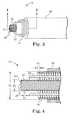
- Figure 3is a view showing the interior construction of the lead 14 of Figure 1 in accordance with an exemplary embodiment.
- the lead 14includes an inner electrode conductor wire 42, an outer electrode conductor wire 44, and an insulation layer 46 disposed radially about the outer electrode conductor wire 44.
- the inner conductor wire 42can have any number of different configurations known in the art, including but not limited to, a coiled configuration, a cable configuration, a straight wire configuration, or the like.
- the inner conductor wire 42comprises a helically-shaped multifilar coil conductor wire having a number of filar strands 48 that are tightly wound together to form an inner electrode used to deliver electrical stimulus energy through the lead 14.
- the inner conductor wire 42includes six or more filar strands 48 forming a helically-shaped conductor.
- the inner conductor wire 42can include a greater or lesser number of filar strands 48.
- the inner conductor wire 42may comprise twelve co-radially wound filar strands 48.
- each of the filar strands 48 forming the inner conductor wire 42can comprise a silver-filled MP35N wire having a silver content of about 10% to 28% by cross-sectional area.
- the inner conductor wire 42has a hollowed configuration, including an interior lumen 50 extending through the wire 42 and adapted to receive a stylet or guidewire that can be used facilitate implantation of the lead 14 within the body.
- the inner conductor wire 42can be fabricated by co-radially winding a number of wire filars about a mandrel having a diameter that is slightly greater than the diameter of the stylet or guidewire to be inserted into the lumen 50.
- the wire filars 48can be tightly wound together during fabrication of the wire 42 such that no gaps or spaces exist between the filar strands 48.
- the outer conductor wire 44is coaxially disposed about the inner conductor wire 42 and has a helically coiled configuration that extends along all or a portion of the length of the lead 14.
- the outer conductor wire 44has a single-filar construction formed from a single wound wire.
- the outer conductor 44has a multifilar construction formed from multiple, co-radially wound wire filars.
- the outer conductor wire 44has a double-filar construction formed from two co-radially wound wire filars.
- the outer conductor wire 44can be spaced radially apart from the inner conductor wire 44, electrically isolating the outer conductor wire 44 from the inner conductor wire 42.
- the outer conductor wire 44is electrically isolated from the inner conductor wire 42 so that the lead 14 can function as a multipolar lead.
- a second layer of insulation 52 interposed between the inner conductor wire 42 and the outer conductor wire 44is further used to electrically isolate the conductor wires 42,44 from each other.
- the second layer of insulation 52may comprise a sheath made from silicon, polyurethane, or other suitable polymeric material.
- Figure 4is a cross-sectional view showing the lead 14 along line 4-4 in Figure 3 .
- the outer conductor wire 44is formed from a small diameter wire to decrease the effective pitch of the wire 44, which, in turn, increases the inductance of the wire 44.
- the wire diameter D 1 of the outer conductor wire 44is in the range of between about 0.001 to 0.006 inches, and more specifically, about 0.003 to 0.004 inches.
- the wire diameter D 1 of the outer conductor wire 44may be greater or lesser, however, depending on the type of lead employed, the configuration of the lead, as well as other factors.
- the overall diameter D 2 of the outer conductor wire 44can also be increased to further increase the inductance of the wire 44.
- the overall diameter D 2 of the outer conductor wire 44is in the range of between about 0.051 to 0.068 inches, and more specifically, about 0.053 to 0.066 inches.
- the overall diameter of the outer conductor wire 44may be greater or lesser, however, depending on the type of lead employed, the configuration of the lead, as well as other factors.
- the overall diameter of the lead 14is in the range of between about 3 to 7 Fr, and more specifically, between about 5 to 6 Fr.
- the outer conductor wire 44is formed from a drawn-filled tube having an outer tubular layer of low-resistive metal or metal-alloy such as MP35N filled with an inner core of electrically conductive material such as silver. Once filled and drawn, the tube is then coiled into a helical shape and attached to the lead 14 using conventional techniques know in the art.
- the outer conductor wire 44comprises a silver-filled MP35N wire having a silver content of about 28% by cross-sectional area.
- the relatively low resistance of the outer tubular metal or metal-alloy forming part of the outer conductor wire 44can be used to offset the increased resistance imparted to the wire 44 from using a smaller diameter wire, as discussed above.
- the material or materials forming the outer conductor wire 44can also be selected so as to impart greater flexibility to the wire 44.
- the outer conductor wire 44may be formed from a material or materials different than the inner conductor wire 42 in order to impart greater resistance to the outer conductor wire 44 to aid in dissipating RF electromagnetic energy received during an MRI procedure.
- the wire filars forming the outer conductor wire 44may comprise a silver-filled MP35N material having a silver content (by cross-sectional area) of about 28% whereas the wire filars forming the inner conductor wire 42 may have a silver content (by cross-sectional area) lower than 28%.
- the inner conductor wire 42has a wire diameter D 3 of between about 0.001 to 0.004 inches, and more specifically, about 0.002 inches.
- the outer diameter D 4 of the inner conductor wire 42is between about 0.020 to 0.028 inches, and more specifically, between about 0.022 to 0.023 inches.
- the dimensions of the inner conductor wire 42, including the wire diameter D 3 and outer diameter D 4may vary, however.
- the lead 14is configured to dissipate RF electromagnetic energy received during a magnetic resonance imaging procedure. This dissipation of electromagnetic energy results in a reduction in heating of body tissue at the location of the electrode(s) 30.
- the increase in inductance of the lead 14also reduces the effects of the electromagnetic energy on the therapeutic electrical current delivered through the lead 14, and in some cases, may permit the lead 14 to continue to provide therapy during the MRI procedure.
- the increase in inductance of the lead 14allows the lead 14 to function at normal device frequencies (e.g., 0.5 Hz to 500 Hz) while acting as a poor antenna at MRI frequencies.
- the illustrative lead 14is described with respect to a cardiac lead for use in providing pacing to a patient's heart 16, the construction of the lead 14 may also be applicable to other medical devices that operate in the presence of electromagnetic fields.
- the construction of the lead 14, including the inner and outer conductor wires 42,44may be used in neural leads adapted for use in neurological applications that utilize MRI imaging.
Landscapes
- Health & Medical Sciences (AREA)
- Heart & Thoracic Surgery (AREA)
- Vascular Medicine (AREA)
- Cardiology (AREA)
- Engineering & Computer Science (AREA)
- Biomedical Technology (AREA)
- Nuclear Medicine, Radiotherapy & Molecular Imaging (AREA)
- Radiology & Medical Imaging (AREA)
- Life Sciences & Earth Sciences (AREA)
- Animal Behavior & Ethology (AREA)
- General Health & Medical Sciences (AREA)
- Public Health (AREA)
- Veterinary Medicine (AREA)
- Electrotherapy Devices (AREA)
- Magnetic Resonance Imaging Apparatus (AREA)
Description
- The present invention relates to medical devices and the simultaneous delivery of diagnostic and therapeutic treatments. More specifically, the present invention relates to implantable medical leads with magnetic shielding and methods of shielding such leads from magnetic fields during medical procedures such as magnetic resonance imaging (MRI).
- Magnetic resonance imaging (MRI) is a non-invasive imaging method that utilizes nuclear magnetic resonance techniques to render images within a patient's body. Typically, MRI systems employ the use of a magnetic coil having a magnetic field strength of between about 0.2 to 3 Teslas. During the procedure, the body tissue is briefly exposed to RF pulses of electromagnetic energy in a plane perpendicular to the magnetic field. The resultant electromagnetic energy from these pulses can be used to image the body tissue by measuring the relaxation properties of the excited atomic nuclei in the tissue.
- During imaging, the electromagnetic radiation produced by the MRI system may be picked up by implantable device leads used in implantable medical devices such as pacemakers or cardiac defibrillators. This energy may be transferred through the lead to the electrode in contact with the tissue, which may lead to elevated temperatures at the point of contact. The degree of tissue heating is typically related to factors such as the length of the lead, the conductivity or impedance of the lead, and the surface area of the lead electrodes. Exposure to a magnetic field may also induce an undesired voltage on the lead.
- The present invention relates to implantable medical leads with magnetic shielding and methods of shielding implantable leads from magnetic fields during medical procedures such as magnetic resonance imaging (MRI). An illustrative medical device includes a pulse generator and a lead having a helically coiled inner electrode conductor wire, a helically coiled outer electrode conductor wire, and one or more insulation layers. The inner electrode conductor wire has a hollowed, multifilar configuration including six or more co-radially wound wire filars. The outer electrode conductor wire is electrically isolated from the inner electrode conductor wire, and has either a single filar or double filar configuration with a relatively high inductance that is adapted to dissipate electromagnetic energy received by the lead during a magnetic resonance procedure.
Figure 1 is a schematic view of an illustrative medical device having a lead implanted within the body of a patient;Figure 2 is a schematic view showing a simplified equivalence circuit for the lead ofFigure 1 ;Figure 3 is a view showing the interior construction of the lead ofFigure 1 in accordance with an exemplary embodiment; andFigure 4 is a cross-sectional view showing the lead along line 4-4 inFigure 3 .- While the invention is amenable to various modifications and alternative forms, specific embodiments have been shown by way of example in the drawings and are described in detail below. The intention, however, is not to limit the invention to the particular embodiments described. On the contrary, the invention is intended to cover all modifications, equivalents, and alternatives falling within the scope of the invention as defined by the appended claims.
Figure 1 is a schematic view of an illustrativemedical device 12 having with a lead implanted within the body of a patient. In the illustrative embodiment depicted, themedical device 12 comprises a pulse generator implanted within the body. Thepulse generator 12 is coupled to alead 14 inserted into the patient'sheart 16. Theheart 16 includes aright atrium 18, aright ventricle 20, aleft atrium 22, and aleft ventricle 24. Thepulse generator 12 can be implanted subcutaneously within the body, typically at a location such as in the patient's chest or abdomen, although other implantation locations are possible.- A
proximal section 26 of thelead 14 can be coupled to or formed integrally with thepulse generator 12. Adistal section 28 of thelead 14, in turn, can be implanted at a desired location in or near theheart 16 such as in theright ventricle 20, as shown. In use, one ormore electrodes 30 on thedistal section 28 of thelead 14 may provide therapy to the patient in the form of an electrical current to theheart 16. In certain embodiments, for example, the electrode(s) 30 may be provided as part of acardiac lead 14 used to treat bradycardia, tachycardia, or other cardiac arrhythmias. - Although the illustrative embodiment depicts only a
single lead 14 inserted into the patient'sheart 16, in other embodiments multiple leads can be utilized so as to electrically stimulate other areas of the heart. 16. In some embodiments, for example, the distal section of a second lead (not shown) may be implanted in theright atrium 18. In addition, or in lieu, another lead may be implanted in or near the left side of the heart 16 (e.g., in the coronary veins) to stimulate the left side of theheart 16. Other types of leads such as epicardial leads may also be utilized in addition to, or in lieu of, thelead 14 depicted inFigure 1 . - During operation, the
lead 14 can be configured to convey electrical signals between thepulse generator 12 and theheart 16. For example, in those embodiments where thepulse generator 12 is a pacemaker, thelead 14 can be utilized to deliver electrical therapeutic stimulus for pacing theheart 16. For example, in the treatment of bradycardia or tachycardia, thepulse generator 12 can be utilized to deliver electrical stimulus in the form of pacing pulses to theheart 16. In other embodiments in which thepulse generator 12 is an implantable cardiac defibrillator, thelead 14 can be utilized to delver electric shocks to theheart 16 in response to an event such as a heart attack or arrhythmia. In some embodiments, thepulse generator 12 includes both pacing and defibrillation capabilities. - When the
pulse generator 12 is subjected to a magnetic field from an MRI scanner or other external magnetic source, electromagnetic radiation is produced within the body that can be picked up by thelead 14 and transferred to the lead electrode(s) 30 in contact with the body tissue. This electromagnetic radiation can cause heating at the interface of the lead electrode(s) 30 and body tissue, and can interfere with the therapeutic electrical currents transmitted by thepulse generator 12 through thelead 14. Figure 2 is a schematic view showing asimplified equivalence circuit 32 for thelead 14 ofFigure 1 , representing the RF energy picked up on thelead 14 from RF electromagnetic energy produced by an MRI scanner. As shown inFigure 2 ,Vi 34 in thecircuit 32 represents an equivalent source of energy picked up by thelead 14 from the MRI scanner. During magnetic resonance imaging, the length of thelead 14 functions similar to an antenna, receiving the RF energy that is transmitted into the body from the MRI scanner. Voltage (Vi) 34 inFigure 2 may represent, for example, the resultant voltage received by thelead 14 from the RF energy. The RF energy picked up by thelead 14 may result, for example, from the rotating RF magnetic field produced by an MRI scanner, which generates an electric field in the plane perpendicular to the rotating magnetic field vector in conductive tissues. The tangential components of these electric fields along the length of thelead 14 couple to thelead 14. The voltage (Vi) 34 is thus equal to the integration of the tangential electric field (i.e., the line integral of the electric field) along the length of thelead 14.- The
ZI parameter 36 in thecircuit 32 represents the equivalent impedance exhibited by thelead 14 at the RF frequency of the MRI scanner. Theimpedance value ZI 36 may represent, for example, the inductance or the equivalent impedance resulting from the parallel inductance and the coil turn by turn capacitance exhibited by thelead 14 at an RF frequency of 64 MHz for a 1.5 Tesla MRI scanner, or at an RF frequency of 128 MHz for a 3 Tesla MRI scanner. The impedance ZI of thelead 14 is a complex quantity having a real part (i.e., resistance) and an imaginary part (i.e., reactance). Zb 38 in thecircuit 32 may represent the impedance of the body tissue at the point of lead contact.Zc 40, in turn, may represent the capacitive coupling of thelead 14 to surrounding body tissue along the length of thelead 14, which may provide a path for the high frequency current (energy) to leak into the surrounding tissue at the RF frequency of the MRI scanner. Minimizing the absorbed energy (represented by source Vi 34) reduces the energy that is transferred to the body tissue at the point of lead contact with the body tissue.- As can be further seen in
Figure 2 , thelead 14 has some amount ofleakage 40 into the surrounding tissue at the RF frequency of the MRI scanner. As further indicated by 38, there is also an impedance at the point of contact of the lead electrode(s) 30 to the surrounding body tissue within theheart 16. The resulting voltage Vb delivered to the body tissue may be related by the following formula:
The temperature at the tip of thelead 14 where contact is typically made to the surrounding tissue is related in part to the power dissipated at 38 (i.e., at "Zb"), which, in turn, is related to the square of Vb. To minimize temperature rises resulting from the power dissipated at 38, it is thus desirable to minimize Vi (34) and Zc (40) while also maximizing the impedance ZI (36) of thelead 14. In some embodiments, the impedance ZI (36) of thelead 14 can be increased at the RF frequency of the MRI scanner, which aids in reducing the energy dissipated into the surrounding body tissue at the point ofcontact 38. - In some embodiments, the impedance of the
lead 14 can be increased by adding inductance to thelead 14 and/or by a suitable construction technique. For example, the inductance of thelead 14 can be increased by increasing the diameter of the conductor coil(s) and/or by decreasing the pitch of the conductor coil(s) used to supply electrical energy to the electrode(s) 30. Decreasing the coil pitch may result in increasing capacitance between successive turns of the coil (i.e., coil turn by turn capacitance). The parallel combination of inductance (from the helical shape of the coil) and the turn by turn capacitance constitutes a resonance circuit. For a helically coiled lead construction, if the resonance frequency of the lead is above the RF frequency of the MRI, then the helical coil acts as an inductor. For an inductor, increasing the cross section of the coil area and/or reducing the coil pitch increases the inductance and, as a result, increases the impedance of thelead 14. - Similar to an antenna, the energy pickup from a lead is related to its resonance length with respect to the wavelength of the frequency of interest. For example, for a dipole antenna, the antenna is considered tuned, or at resonance, when the antenna length is half the wavelength or an integer multiple of the wavelength. At resonance lengths, the energy pickup of the antenna is maximized. In a similar manner, and in some embodiments, the
lead 14 can be detuned so as to prevent resonance within thelead 14, and thus minimize the voltage Vi. For the illustrative embodiment shown inFigure 1 , for example, the lead 14 functions as an antenna having a resonance frequency at length L = integer x λ/2. In some embodiments, the length of thelead 14 and/or the construction parameters of thelead 14 affecting the wavelength can be chosen so as to avoid resonance within thelead 14. - In some embodiments, in addition to detuning the length of the
lead 14 with respect to the wavelength of the MRI induced RF energy, shielding can also be added to thelead 14 to further reduce the amount of electromagnetic energy picked up from thelead 14. For example, the energy picked up from the shielding can be coupled to the patient's body along the length of thelead 14, preventing the energy from coupling to the lead tip. The transfer of intercepted energy by the shielding along the length of the shielding/lead can also be inhibited by dissipating the energy as resistive loss, using resistive material for the shielding construction. Figure 3 is a view showing the interior construction of thelead 14 ofFigure 1 in accordance with an exemplary embodiment. In the embodiment ofFigure 3 , thelead 14 includes an innerelectrode conductor wire 42, an outerelectrode conductor wire 44, and aninsulation layer 46 disposed radially about the outerelectrode conductor wire 44. Theinner conductor wire 42 can have any number of different configurations known in the art, including but not limited to, a coiled configuration, a cable configuration, a straight wire configuration, or the like.- In the illustrative embodiment of
Figure 3 , theinner conductor wire 42 comprises a helically-shaped multifilar coil conductor wire having a number offilar strands 48 that are tightly wound together to form an inner electrode used to deliver electrical stimulus energy through thelead 14. In one embodiment, for example, theinner conductor wire 42 includes six or morefilar strands 48 forming a helically-shaped conductor. In other embodiments, theinner conductor wire 42 can include a greater or lesser number offilar strands 48. In one embodiment, for example, theinner conductor wire 42 may comprise twelve co-radiallywound filar strands 48. In some embodiments, each of thefilar strands 48 forming theinner conductor wire 42 can comprise a silver-filled MP35N wire having a silver content of about 10% to 28% by cross-sectional area. - In some embodiments, the
inner conductor wire 42 has a hollowed configuration, including aninterior lumen 50 extending through thewire 42 and adapted to receive a stylet or guidewire that can be used facilitate implantation of thelead 14 within the body. In certain embodiments, theinner conductor wire 42 can be fabricated by co-radially winding a number of wire filars about a mandrel having a diameter that is slightly greater than the diameter of the stylet or guidewire to be inserted into thelumen 50. To improve the torque characteristics of thewire 42, thewire filars 48 can be tightly wound together during fabrication of thewire 42 such that no gaps or spaces exist between thefilar strands 48. - As further shown in
Figure 3 , and in some embodiments, theouter conductor wire 44 is coaxially disposed about theinner conductor wire 42 and has a helically coiled configuration that extends along all or a portion of the length of thelead 14. In some embodiments, theouter conductor wire 44 has a single-filar construction formed from a single wound wire. In other embodiments, theouter conductor 44 has a multifilar construction formed from multiple, co-radially wound wire filars. In one embodiment, for example, theouter conductor wire 44 has a double-filar construction formed from two co-radially wound wire filars. - The
outer conductor wire 44 can be spaced radially apart from theinner conductor wire 44, electrically isolating theouter conductor wire 44 from theinner conductor wire 42. In some embodiments, for example, theouter conductor wire 44 is electrically isolated from theinner conductor wire 42 so that thelead 14 can function as a multipolar lead. In certain embodiments, a second layer ofinsulation 52 interposed between theinner conductor wire 42 and theouter conductor wire 44 is further used to electrically isolate theconductor wires insulation 52 may comprise a sheath made from silicon, polyurethane, or other suitable polymeric material. Figure 4 is a cross-sectional view showing thelead 14 along line 4-4 inFigure 3 . As further shown inFigure 4 , and in some embodiments, theouter conductor wire 44 is formed from a small diameter wire to decrease the effective pitch of thewire 44, which, in turn, increases the inductance of thewire 44. In some embodiments, for example, the wire diameter D1 of theouter conductor wire 44 is in the range of between about 0.001 to 0.006 inches, and more specifically, about 0.003 to 0.004 inches. The wire diameter D1 of theouter conductor wire 44 may be greater or lesser, however, depending on the type of lead employed, the configuration of the lead, as well as other factors. Due to the relatively small diameter D1 of theouter conductor wire 44, a greater number of coil turns is present along the length of thelead 14 in comparison to more conventional leads with larger wire diameters, which increases the impedance of theconductor wire 44. This increased impedance aids in reducing the energy dissipated into the surrounding body tissue at or near the lead electrode(s) 30.- The overall diameter D2 of the
outer conductor wire 44 can also be increased to further increase the inductance of thewire 44. In some embodiments, for example, the overall diameter D2 of theouter conductor wire 44 is in the range of between about 0.051 to 0.068 inches, and more specifically, about 0.053 to 0.066 inches. The overall diameter of theouter conductor wire 44 may be greater or lesser, however, depending on the type of lead employed, the configuration of the lead, as well as other factors. In some embodiments, the overall diameter of thelead 14 is in the range of between about 3 to 7 Fr, and more specifically, between about 5 to 6 Fr. - In some embodiments, the
outer conductor wire 44 is formed from a drawn-filled tube having an outer tubular layer of low-resistive metal or metal-alloy such as MP35N filled with an inner core of electrically conductive material such as silver. Once filled and drawn, the tube is then coiled into a helical shape and attached to thelead 14 using conventional techniques know in the art. In one embodiment, theouter conductor wire 44 comprises a silver-filled MP35N wire having a silver content of about 28% by cross-sectional area. In use, the relatively low resistance of the outer tubular metal or metal-alloy forming part of theouter conductor wire 44 can be used to offset the increased resistance imparted to thewire 44 from using a smaller diameter wire, as discussed above. In some embodiments, the material or materials forming theouter conductor wire 44 can also be selected so as to impart greater flexibility to thewire 44. - The
outer conductor wire 44 may be formed from a material or materials different than theinner conductor wire 42 in order to impart greater resistance to theouter conductor wire 44 to aid in dissipating RF electromagnetic energy received during an MRI procedure. In one embodiment, for example, the wire filars forming theouter conductor wire 44 may comprise a silver-filled MP35N material having a silver content (by cross-sectional area) of about 28% whereas the wire filars forming theinner conductor wire 42 may have a silver content (by cross-sectional area) lower than 28%. - As further shown in
Figure 4 , and in some embodiments, theinner conductor wire 42 has a wire diameter D3 of between about 0.001 to 0.004 inches, and more specifically, about 0.002 inches. In certain embodiments, the outer diameter D4 of theinner conductor wire 42 is between about 0.020 to 0.028 inches, and more specifically, between about 0.022 to 0.023 inches. The dimensions of theinner conductor wire 42, including the wire diameter D3 and outer diameter D4 may vary, however. - By increasing the inductance of the
lead 14, and in particular the inductance of theouter conductor wire 44, thelead 14 is configured to dissipate RF electromagnetic energy received during a magnetic resonance imaging procedure. This dissipation of electromagnetic energy results in a reduction in heating of body tissue at the location of the electrode(s) 30. The increase in inductance of thelead 14 also reduces the effects of the electromagnetic energy on the therapeutic electrical current delivered through thelead 14, and in some cases, may permit thelead 14 to continue to provide therapy during the MRI procedure. In some embodiments, for example, the increase in inductance of thelead 14 allows thelead 14 to function at normal device frequencies (e.g., 0.5 Hz to 500 Hz) while acting as a poor antenna at MRI frequencies. - While the
illustrative lead 14 is described with respect to a cardiac lead for use in providing pacing to a patient'sheart 16, the construction of thelead 14 may also be applicable to other medical devices that operate in the presence of electromagnetic fields. For example, the construction of thelead 14, including the inner andouter conductor wires - Various modifications and additions can be made to the exemplary embodiments discussed without departing from the scope of the present invention. For example, while the embodiments described above refer to particular features, the scope of this invention also includes embodiments having different combinations of features and embodiments that do not include all of the described features. Accordingly, the scope of the present invention is intended to embrace all such alternatives, modifications, and variations as fall within the scope of the claims.

Claims (10)
- An implantable medical lead, comprising:an inner electrode conductor wire helically disposed along all or a portion of a length of the lead, the inner electrode conductor wire having a hollowed, multifilar configuration including six or more co-radially wound wire filars, each of the wire filars of the inner electrode conductor wire formed of a silver-filled MP35N wire;an outer electrode conductor wire helically disposed about and spaced apart from the inner electrode conductor wire along all or a portion of the length of the lead, the outer electrode conductor wire having a single or double filar configuration, each wire filar of the outer electrode conductor wire formed of a silver-filled MP35N wire having a different silver content by cross-sectional area than the inner electrode conductor wire;at least one insulation layer (52) disposed radially about the inner electrode conductor wire to electrically isolate the conductor wires from each other; andwherein the outer electrode conductor wire is configured to dissipate electromagnetic energy received by the lead during a magnetic resonance imaging procedure.
- The medical lead of claim 1, wherein the inner electrode conductor wire includes twelve co-radially wound wire filars.
- The medical lead of claim 1, wherein each wire filar of the inner electrode conductor wire has a wire diameter of between about 0.025 to 0.102 mm (0.001 to 0.004 inches).
- The medical lead of claim 1, wherein the inner electrode conductor wire has an outer diameter of between about 0.508 to 0.711 mm (0.020 to 0.028 inches).
- The medical lead of claim 1, wherein each wire filar of the inner electrode conductor wire comprises a silver-filled MP35N material having a silver content of less than about 28% by cross-sectional area.
- The medical lead of claim 1, wherein each wire filar of the outer electrode conductor wire comprises a silver-filled MP35N material having a silver content of about 28% by cross-sectional area.
- The medical lead of claim 1, wherein the outer electrode conductor wire has a wire diameter of between about 0.025 to 0.152 mm (0.001 to 0.006 inches).
- The medical lead of claim 1, wherein the outer electrode conductor wire has an outer diameter of between about 1.295 to 1.727 mm (0.051 to 0.068 inches).
- The medical lead of claim 1, further comprising an insulation layer disposed about the outer electrode conductor wire.
- A medical device, comprising:a pulse generator;a lead electrically coupled to the pulse generator, the lead being a medical lead of any of claims 1-9.
Applications Claiming Priority (2)
| Application Number | Priority Date | Filing Date | Title |
|---|---|---|---|
| US2666108P | 2008-02-06 | 2008-02-06 | |
| PCT/US2009/032838WO2009100003A1 (en) | 2008-02-06 | 2009-02-02 | Lead with mri compatible design features |
Publications (2)
| Publication Number | Publication Date |
|---|---|
| EP2249920A1 EP2249920A1 (en) | 2010-11-17 |
| EP2249920B1true EP2249920B1 (en) | 2015-07-01 |
Family
ID=40521968
Family Applications (1)
| Application Number | Title | Priority Date | Filing Date |
|---|---|---|---|
| EP09707389.4ANot-in-forceEP2249920B1 (en) | 2008-02-06 | 2009-02-02 | Lead with mri compatible design features |
Country Status (6)
| Country | Link |
|---|---|
| US (2) | US8244346B2 (en) |
| EP (1) | EP2249920B1 (en) |
| JP (1) | JP5149399B2 (en) |
| CN (1) | CN101925379B (en) |
| AU (1) | AU2009212697B2 (en) |
| WO (1) | WO2009100003A1 (en) |
Families Citing this family (58)
| Publication number | Priority date | Publication date | Assignee | Title |
|---|---|---|---|---|
| US7610101B2 (en) | 2006-11-30 | 2009-10-27 | Cardiac Pacemakers, Inc. | RF rejecting lead |
| WO2009076169A2 (en)* | 2007-12-06 | 2009-06-18 | Cardiac Pacemakers, Inc. | Implantable lead with shielding |
| AU2008335462B2 (en)* | 2007-12-06 | 2014-02-20 | Cardiac Pacemakers, Inc. | Implantable lead having a variable coil conductor pitch |
| US8275464B2 (en) | 2007-12-06 | 2012-09-25 | Cardiac Pacemakers, Inc. | Leads with high surface resistance |
| WO2009100003A1 (en) | 2008-02-06 | 2009-08-13 | Cardiac Pacemakers, Inc. | Lead with mri compatible design features |
| WO2009134901A1 (en)* | 2008-04-30 | 2009-11-05 | Medtronic, Inc. | Magnetic resonance imaging shunt electrodes with self-healing coatings |
| US8103360B2 (en)* | 2008-05-09 | 2012-01-24 | Foster Arthur J | Medical lead coil conductor with spacer element |
| US8178318B2 (en) | 2008-08-06 | 2012-05-15 | Praxair Technology, Inc. | Method for controlling pH, osmolality and dissolved carbon dioxide levels in a mammalian cell culture process to enhance cell viability and biologic product yield |
| US8335570B2 (en) | 2008-10-09 | 2012-12-18 | Boston Scientific Neuromodulation Corporation | Electrical stimulation leads having RF compatibility and methods of use and manufacture |
| US8644951B1 (en)* | 2009-12-02 | 2014-02-04 | University Of Central Florida Research Foundation, Inc. | Medical devices having MRI compatible metal alloys |
| US9084883B2 (en)* | 2009-03-12 | 2015-07-21 | Cardiac Pacemakers, Inc. | Thin profile conductor assembly for medical device leads |
| ES2547713T3 (en)* | 2009-06-26 | 2015-10-08 | Cardiac Pacemakers, Inc. | Bypass of a medical device that includes a single-coil coil with improved torque transmission capacity and reduced RM heating |
| US8335572B2 (en) | 2009-10-08 | 2012-12-18 | Cardiac Pacemakers, Inc. | Medical device lead including a flared conductive coil |
| US9254380B2 (en) | 2009-10-19 | 2016-02-09 | Cardiac Pacemakers, Inc. | MRI compatible tachycardia lead |
| WO2011053199A1 (en)* | 2009-10-30 | 2011-05-05 | St. Jude Medical Ab | A medical implantable lead |
| US9014815B2 (en)* | 2009-11-19 | 2015-04-21 | Medtronic, Inc. | Electrode assembly in a medical electrical lead |
| US8306630B2 (en)* | 2009-12-30 | 2012-11-06 | Cardiac Pacemakers, Inc. | Apparatus to selectively increase medical device lead inner conductor inductance |
| US9750944B2 (en) | 2009-12-30 | 2017-09-05 | Cardiac Pacemakers, Inc. | MRI-conditionally safe medical device lead |
| JP2013512071A (en)* | 2009-12-31 | 2013-04-11 | カーディアック ペースメイカーズ, インコーポレイテッド | MRI safe and multipolar active fixed stimulation lead with colloidal structure |
| WO2011081713A1 (en) | 2009-12-31 | 2011-07-07 | Cardiac Pacemakers, Inc. | Mri conditionally safe lead with multi-layer conductor |
| US8391994B2 (en) | 2009-12-31 | 2013-03-05 | Cardiac Pacemakers, Inc. | MRI conditionally safe lead with low-profile multi-layer conductor for longitudinal expansion |
| US8818509B2 (en) | 2010-02-11 | 2014-08-26 | Biotronik Se & Co. Kg | Implantable element and electronic implant |
| WO2011103444A1 (en) | 2010-02-19 | 2011-08-25 | Cardiac Pacemakers, Inc. | Lead including conductors configured for reduced mri-induced currents |
| US9126031B2 (en) | 2010-04-30 | 2015-09-08 | Medtronic, Inc. | Medical electrical lead with conductive sleeve head |
| US8825181B2 (en) | 2010-08-30 | 2014-09-02 | Cardiac Pacemakers, Inc. | Lead conductor with pitch and torque control for MRI conditionally safe use |
| US8630718B2 (en)* | 2010-11-18 | 2014-01-14 | Cardiac Pacemakers, Inc. | Insulative structure for MRI compatible leads |
| US8509915B2 (en)* | 2010-12-17 | 2013-08-13 | Biotronik Se & Co. Kg | Implantable electrode line device for reducing undesirable effects of electromagnetic fields |
| US8433408B2 (en)* | 2011-04-27 | 2013-04-30 | Medtronic, Inc. | Pacing in the presence of electromagnetic interference |
| CN102327668B (en)* | 2011-08-12 | 2014-01-22 | 清华大学 | Implanted bioelectrode and medical assembly comprising same |
| CN103093865B (en) | 2011-10-28 | 2015-06-03 | 清华大学 | Pacemaker electrode line and pacemaker |
| CN103093858B (en)* | 2011-10-28 | 2016-10-19 | 清华大学 | Pacemaker lead and pacemaker |
| CN103093860B (en)* | 2011-10-28 | 2016-04-13 | 清华大学 | Pacing lead and pacemaker |
| CN103083808B (en) | 2011-10-28 | 2016-04-27 | 清华大学 | Pacing lead and pacemaker |
| CN103083807B (en) | 2011-10-28 | 2016-04-27 | 清华大学 | The preparation method of pacing lead |
| CN103083806B (en) | 2011-10-28 | 2016-06-08 | 清华大学 | Pacing lead and pacemaker |
| CN103093859B (en) | 2011-10-28 | 2015-08-26 | 清华大学 | Pacing lead and pacemaker |
| US8666512B2 (en) | 2011-11-04 | 2014-03-04 | Cardiac Pacemakers, Inc. | Implantable medical device lead including inner coil reverse-wound relative to shocking coil |
| CN103957979B (en)* | 2011-11-29 | 2017-09-12 | 皇家飞利浦有限公司 | For the pipe being introduced into subject |
| US20130274829A1 (en)* | 2012-04-17 | 2013-10-17 | Boston Scientific Neuromodulation Corporation | Neurostimulation device having frequency selective surface to prevent electromagnetic interference during mri |
| AU2013249088B2 (en) | 2012-04-20 | 2015-12-03 | Cardiac Pacemakers, Inc. | Implantable medical device lead including a unifilar coiled cable |
| US8954168B2 (en) | 2012-06-01 | 2015-02-10 | Cardiac Pacemakers, Inc. | Implantable device lead including a distal electrode assembly with a coiled component |
| US8666511B2 (en) | 2012-07-30 | 2014-03-04 | Medtronic, Inc. | Magnetic resonance imaging compatible medical electrical lead and method of making the same |
| US10358723B2 (en) | 2012-08-16 | 2019-07-23 | University Of Central Florida Research Foundation, Inc. | System and method for surface modification by laser diffusion |
| JP6069499B2 (en)* | 2012-08-31 | 2017-02-01 | カーディアック ペースメイカーズ, インコーポレイテッド | Lead wire with low peak MRI heating |
| CN102824689B (en) | 2012-09-07 | 2014-12-24 | 清华大学 | Implanted electrode and preparation method thereof and medical assembly comprising implanted electrode |
| US8983623B2 (en) | 2012-10-18 | 2015-03-17 | Cardiac Pacemakers, Inc. | Inductive element for providing MRI compatibility in an implantable medical device lead |
| US10501929B2 (en) | 2013-09-30 | 2019-12-10 | Drew P. HENRY | Hollow connector sleeve with interlocking components |
| WO2015123249A1 (en) | 2014-02-11 | 2015-08-20 | Cardiac Pacemakers, Inc | Rf shield for an implantable lead |
| WO2015130753A1 (en) | 2014-02-26 | 2015-09-03 | Cardiac Pacemakers, Inc | Construction of an mri-safe tachycardia lead |
| CN104083823B (en)* | 2014-06-27 | 2017-09-26 | 清华大学 | A kind of implanted electrode compatible MRI |
| CN104274902B (en)* | 2014-10-10 | 2017-09-22 | 清华大学 | The implanted electrode and its manufacture method of a kind of MRI compatible |
| US10185002B2 (en)* | 2015-06-04 | 2019-01-22 | General Electric Company | Systems and methods for MRI common mode traps |
| US20170001001A1 (en)* | 2015-07-01 | 2017-01-05 | Cardiac Pacemakers, Inc. | Left side single pass lead for la and lv sensing and pacing |
| CN105047352B (en)* | 2015-09-17 | 2017-03-22 | 中国工程物理研究院流体物理研究所 | Close-winding spiral coil and manufacturing method thereof |
| GB2559595B (en)* | 2017-02-10 | 2021-09-01 | Creo Medical Ltd | Electrosurgical apparatus and electrosurgical instrument |
| US11197612B2 (en)* | 2017-10-05 | 2021-12-14 | American University Of Beirut | Non-invasive biological, chemical markers and tracers monitoring device in blood including glucose monitoring using adaptive RF circuits and antenna design |
| CN110520042B (en)* | 2019-07-17 | 2022-05-03 | 诺尔医疗(深圳)有限公司 | deep intracranial electrodes |
| WO2021007817A1 (en)* | 2019-07-17 | 2021-01-21 | 诺尔医疗(深圳)有限公司 | Deep intracranial electrode |
Family Cites Families (188)
| Publication number | Priority date | Publication date | Assignee | Title |
|---|---|---|---|---|
| US3614692A (en)* | 1970-06-02 | 1971-10-19 | Magnetech Ind Inc | Variable induction device |
| US4135518A (en)* | 1976-05-21 | 1979-01-23 | Medtronic, Inc. | Body implantable lead and electrode |
| US4131759A (en)* | 1977-08-10 | 1978-12-26 | United States Steel Corporation | Slip sleeve mechanism for a strength tapered caged armored electromechanical cable |
| US4404125A (en)* | 1981-10-14 | 1983-09-13 | General Electric Company | Polyphenylene ether resin compositions for EMI electromagnetic interference shielding |
| US4484586A (en)* | 1982-05-27 | 1984-11-27 | Berkley & Company, Inc. | Hollow conductive medical tubing |
| GB2126466B (en) | 1982-07-01 | 1986-03-12 | Molins Plc | Conveying and uniting rod-like articles of the tobacco industry |
| US4493329A (en)* | 1982-08-19 | 1985-01-15 | Lynn Crawford | Implantable electrode having different stiffening and curvature maintaining characteristics along its length |
| US4643202A (en)* | 1985-04-15 | 1987-02-17 | Cordis Corporation | Multi-material insulation sheath for pacer lead |
| US4869970A (en) | 1986-07-14 | 1989-09-26 | Shipley Company Inc. | Radiation attenuation shielding |
| US5056516A (en)* | 1989-11-02 | 1991-10-15 | Intermedics, Inc. | Implantable endocordial lead with torque-transmitting lanyard |
| US5243911A (en) | 1990-09-18 | 1993-09-14 | Dow Robert L | Attenuator for protecting electronic equipment from undesired exposure to RF energy and/or lightning |
| US5217010A (en) | 1991-05-28 | 1993-06-08 | The Johns Hopkins University | Ecg amplifier and cardiac pacemaker for use during magnetic resonance imaging |
| US5222506A (en)* | 1991-07-29 | 1993-06-29 | Medtronic, Inc. | Implantable medical lead with electrical cross-over adaptor |
| US5246014A (en)* | 1991-11-08 | 1993-09-21 | Medtronic, Inc. | Implantable lead system |
| US5241957A (en)* | 1991-11-18 | 1993-09-07 | Medtronic, Inc. | Bipolar temporary pacing lead and connector and permanent bipolar nerve wire |
| US5231996A (en)* | 1992-01-28 | 1993-08-03 | Medtronic, Inc. | Removable endocardial lead |
| WO1993017074A1 (en)* | 1992-02-24 | 1993-09-02 | Baxter International Inc. | Polymer blends for torque transmitting catheters |
| US5447533A (en) | 1992-09-03 | 1995-09-05 | Pacesetter, Inc. | Implantable stimulation lead having an advanceable therapeutic drug delivery system |
| JPH06205842A (en)* | 1992-12-04 | 1994-07-26 | Siemens Ag | Lead assembly for implantable medical device |
| US5330522A (en)* | 1992-12-29 | 1994-07-19 | Siemens Pacesetter, Inc. | Ring electrode for a multilumen lead and method of constructing a multilumen lead |
| CA2152604C (en) | 1993-02-01 | 2000-05-09 | Thomas M. Soukup | An implantable electrode |
| US5378234A (en)* | 1993-03-15 | 1995-01-03 | Pilot Cardiovascular Systems, Inc. | Coil polymer composite |
| US5354327A (en) | 1993-04-07 | 1994-10-11 | Medtronic, Inc. | Conductor coil with specific ratio of torque to bending stiffness |
| CA2174129C (en)* | 1993-10-14 | 2004-03-09 | Sidney D. Fleischman | Electrode elements for forming lesion patterns |
| US5456707A (en)* | 1993-10-22 | 1995-10-10 | Vitatron Medical Bv | Pacing lead with improved torsion characteristics |
| JPH07178176A (en)* | 1993-12-24 | 1995-07-18 | Terumo Corp | Catheter |
| US5483022A (en)* | 1994-04-12 | 1996-01-09 | Ventritex, Inc. | Implantable conductor coil formed from cabled composite wire |
| US5618208A (en) | 1994-06-03 | 1997-04-08 | Siemens Medical Systems, Inc. | Fully insulated, fully shielded electrical connector arrangement |
| US5574249A (en) | 1994-07-18 | 1996-11-12 | Lindsay Audiophile Inc. | High resistivity inner shields for cabinets housing electronic circuitry |
| US5522875A (en)* | 1994-07-28 | 1996-06-04 | Medtronic, Inc. | Medical electrical lead system having a torque transfer stylet |
| WO1996006655A1 (en) | 1994-08-29 | 1996-03-07 | Angeion Corporation | Low profile defibrillation catheter |
| US5522872A (en)* | 1994-12-07 | 1996-06-04 | Ventritex, Inc. | Electrode-conductor sleeve joint for cardiac lead |
| US5599576A (en)* | 1995-02-06 | 1997-02-04 | Surface Solutions Laboratories, Inc. | Medical apparatus with scratch-resistant coating and method of making same |
| DE69606845T2 (en)* | 1995-04-28 | 2000-06-15 | Target Therapeutics, Inc. | High performance catheter with braided element |
| US5584873A (en)* | 1995-05-08 | 1996-12-17 | Medtronic, Inc. | Medical lead with compression lumens |
| US5728149A (en) | 1995-12-20 | 1998-03-17 | Medtronic, Inc. | Integral spiral band electrode for transvenous defibrillation leads |
| US5927345A (en) | 1996-04-30 | 1999-07-27 | Target Therapeutics, Inc. | Super-elastic alloy braid structure |
| US5800496A (en)* | 1996-06-24 | 1998-09-01 | Medtronic, Inc. | Medical electrical lead having a crush resistant lead body |
| US5810887A (en)* | 1996-08-23 | 1998-09-22 | Rhythm Technologies, Inc. | Temporary catheter |
| US5760341A (en)* | 1996-09-10 | 1998-06-02 | Medtronic, Inc. | Conductor cable for biomedical lead |
| US5968087A (en)* | 1996-12-19 | 1999-10-19 | Medtronic, Inc. | Multi-component lead body for medical electrical leads |
| EP0971767A2 (en)* | 1996-12-19 | 2000-01-19 | Medtronic, Inc. | Medical electrical lead |
| US6038472A (en)* | 1997-04-29 | 2000-03-14 | Medtronic, Inc. | Implantable defibrillator and lead system |
| US6078840A (en)* | 1997-04-30 | 2000-06-20 | Medtronic, Inc. | Medical electrical lead having improved fixation |
| US6103636A (en) | 1997-08-20 | 2000-08-15 | Micron Technology, Inc. | Method and apparatus for selective removal of material from wafer alignment marks |
| DE19736449A1 (en)* | 1997-08-21 | 1999-02-25 | Gfe Met & Mat Gmbh | Composite |
| US6249708B1 (en)* | 1997-08-26 | 2001-06-19 | Angeion Corporation | Fluted channel construction for a multi-conductor catheter lead |
| US6501994B1 (en)* | 1997-12-24 | 2002-12-31 | Cardiac Pacemakers, Inc. | High impedance electrode tip |
| US5957970A (en)* | 1998-02-18 | 1999-09-28 | Medtronic, Inc. | Method of fabricating a medical electrical lead |
| US5957966A (en) | 1998-02-18 | 1999-09-28 | Intermedics Inc. | Implantable cardiac lead with multiple shape memory polymer structures |
| US6256541B1 (en)* | 1998-04-17 | 2001-07-03 | Cardiac Pacemakers, Inc. | Endocardial lead having defibrillation and sensing electrodes with septal anchoring |
| JPH11333000A (en)* | 1998-05-27 | 1999-12-07 | Cardio Pacing Research Laboratory:Kk | Electrode lead for biological implantation |
| US6134478A (en) | 1998-06-05 | 2000-10-17 | Intermedics Inc. | Method for making cardiac leads with zone insulated electrodes |
| US7345684B2 (en) | 1998-06-25 | 2008-03-18 | Intel Corporation | Perceptually based display |
| US6208881B1 (en)* | 1998-10-20 | 2001-03-27 | Micropure Medical, Inc. | Catheter with thin film electrodes and method for making same |
| US9061139B2 (en) | 1998-11-04 | 2015-06-23 | Greatbatch Ltd. | Implantable lead with a band stop filter having a capacitor in parallel with an inductor embedded in a dielectric body |
| US8244370B2 (en)* | 2001-04-13 | 2012-08-14 | Greatbatch Ltd. | Band stop filter employing a capacitor and an inductor tank circuit to enhance MRI compatibility of active medical devices |
| US6141593A (en) | 1998-11-10 | 2000-10-31 | Intermedics Inc. | Cardiac lead with ETEE coated DBS coil |
| US6083216A (en) | 1999-01-05 | 2000-07-04 | Intermedics Inc. | Bent cardiac lead with shape memory torque coil |
| US6259954B1 (en) | 1999-02-18 | 2001-07-10 | Intermedics Inc. | Endocardial difibrillation lead with strain-relief coil connection |
| US6400992B1 (en)* | 1999-03-18 | 2002-06-04 | Medtronic, Inc. | Co-extruded, multi-lumen medical lead |
| US6813251B1 (en) | 1999-07-27 | 2004-11-02 | Intel Corporation | Split Transaction protocol for a bus system |
| US6408213B1 (en)* | 1999-09-29 | 2002-06-18 | Cardiac Pacemakers, Inc. | Low profile, ventricular, transvenous, epicardial defibrillation lead |
| US6295476B1 (en)* | 1999-11-01 | 2001-09-25 | Medtronic, Inc. | Medical lead conductor fracture visualization method and apparatus |
| US6556873B1 (en) | 1999-11-29 | 2003-04-29 | Medtronic, Inc. | Medical electrical lead having variable bending stiffness |
| US6510345B1 (en)* | 2000-04-24 | 2003-01-21 | Medtronic, Inc. | System and method of bridging a transreceiver coil of an implantable medical device during non-communication periods |
| US6516230B2 (en)* | 2000-04-26 | 2003-02-04 | Medtronic, Inc. | Medical electrical lead with fiber core |
| US7013182B1 (en)* | 2000-05-04 | 2006-03-14 | Cardiac Pacemakers, Inc. | Conductive polymer sheath on defibrillator shocking coils |
| US6850803B1 (en)* | 2000-06-16 | 2005-02-01 | Medtronic, Inc. | Implantable medical device with a recharging coil magnetic shield |
| US6501991B1 (en)* | 2000-06-21 | 2002-12-31 | Medtronic, Inc. | Electrically-isolated multiple conductor lead body |
| US6493591B1 (en)* | 2000-07-19 | 2002-12-10 | Medtronic, Inc. | Implantable active fixation lead with guidewire tip |
| US6721604B1 (en)* | 2000-07-27 | 2004-04-13 | Micronet Medical, Inc. | Reduced diameter, low resistance medical electrical lead |
| US6456888B1 (en)* | 2000-08-18 | 2002-09-24 | Cardiac Pacemakers, Inc. | Geometry for coupling and electrode to a conductor |
| US6564107B1 (en) | 2000-08-21 | 2003-05-13 | Cardiac Pacemakers, Inc. | Coil-less lead system |
| EP1336116A1 (en)* | 2000-11-24 | 2003-08-20 | Koninklijke Philips Electronics N.V. | Invasive device provided with a segmented electrical connection conductor |
| US6522920B2 (en)* | 2000-12-11 | 2003-02-18 | Pacesetter, Inc. | System and method of protecting transformer-driven switches from external magnetic fields |
| US20030063946A1 (en) | 2000-12-18 | 2003-04-03 | Janet Williams | Disposable lotion applicator |
| US20020116028A1 (en)* | 2001-02-20 | 2002-08-22 | Wilson Greatbatch | MRI-compatible pacemaker with pulse carrying photonic catheter providing VOO functionality |
| US6829509B1 (en) | 2001-02-20 | 2004-12-07 | Biophan Technologies, Inc. | Electromagnetic interference immune tissue invasive system |
| US20050283167A1 (en) | 2003-08-25 | 2005-12-22 | Biophan Technologies, Inc. | Medical device with an electrically conductive anti-antenna member |
| US6949929B2 (en)* | 2003-06-24 | 2005-09-27 | Biophan Technologies, Inc. | Magnetic resonance imaging interference immune device |
| US6854994B2 (en)* | 2001-04-19 | 2005-02-15 | Medtronic, Inc. | Medical electrical lead connector arrangement including anti-rotation means |
| US6931285B2 (en)* | 2001-04-17 | 2005-08-16 | Medtronic, Inc. | Drive shaft seal for a medical electrical lead |
| US7257449B2 (en) | 2001-05-30 | 2007-08-14 | Cardiac Pacemakers, Inc. | Extendable/retractable lead having downsized lead body |
| US6671554B2 (en)* | 2001-09-07 | 2003-12-30 | Medtronic Minimed, Inc. | Electronic lead for a medical implant device, method of making same, and method and apparatus for inserting same |
| US7904161B2 (en)* | 2001-10-22 | 2011-03-08 | Oscor Inc. | Lead adaptor having low resistance conductors and/or encapsulated housing |
| US6871091B2 (en) | 2001-10-31 | 2005-03-22 | Medtronic, Inc. | Apparatus and method for shunting induced currents in an electrical lead |
| US6944489B2 (en)* | 2001-10-31 | 2005-09-13 | Medtronic, Inc. | Method and apparatus for shunting induced currents in an electrical lead |
| US6671562B2 (en)* | 2001-11-09 | 2003-12-30 | Oscor Inc. | High impedance drug eluting cardiac lead |
| US6978185B2 (en)* | 2001-11-09 | 2005-12-20 | Oscor Inc. | Multifilar conductor for cardiac leads |
| JP2005510384A (en)* | 2001-11-22 | 2005-04-21 | ケーニツヒ ウント バウエル アクチエンゲゼルシヤフト | Use of ink in printing apparatus and printing apparatus of rotary printing press |
| US6506972B1 (en) | 2002-01-22 | 2003-01-14 | Nanoset, Llc | Magnetically shielded conductor |
| US6999821B2 (en)* | 2002-01-18 | 2006-02-14 | Pacesetter, Inc. | Body implantable lead including one or more conductive polymer electrodes and methods for fabricating same |
| US7082328B2 (en) | 2002-01-29 | 2006-07-25 | Medtronic, Inc. | Methods and apparatus for controlling a pacing system in the presence of EMI |
| US20030144718A1 (en) | 2002-01-29 | 2003-07-31 | Zeijlemaker Volkert A. | Method and apparatus for shielding coating for MRI resistant electrode systems |
| US20030144719A1 (en)* | 2002-01-29 | 2003-07-31 | Zeijlemaker Volkert A. | Method and apparatus for shielding wire for MRI resistant electrode systems |
| US6985775B2 (en)* | 2002-01-29 | 2006-01-10 | Medtronic, Inc. | Method and apparatus for shunting induced currents in an electrical lead |
| US7050855B2 (en) | 2002-01-29 | 2006-05-23 | Medtronic, Inc. | Medical implantable system for reducing magnetic resonance effects |
| EP1469910B1 (en) | 2002-01-29 | 2006-12-06 | Medtronic, Inc. | Conditioning of coupled electromagnetic signals on a lead |
| US20030144720A1 (en)* | 2002-01-29 | 2003-07-31 | Villaseca Eduardo H. | Electromagnetic trap for a lead |
| US8396568B2 (en) | 2002-04-11 | 2013-03-12 | Medtronic, Inc. | Medical electrical lead body designs incorporating energy dissipating shunt |
| US20030216800A1 (en) | 2002-04-11 | 2003-11-20 | Medtronic, Inc. | Implantable medical device conductor insulation and process for forming |
| US20030204217A1 (en) | 2002-04-25 | 2003-10-30 | Wilson Greatbatch | MRI-safe cardiac stimulation device |
| US7158837B2 (en) | 2002-07-10 | 2007-01-02 | Oscor Inc. | Low profile cardiac leads |
| US7139613B2 (en) | 2002-09-25 | 2006-11-21 | Medtronic, Inc. | Implantable medical device communication system with pulsed power biasing |
| US7292894B2 (en)* | 2002-09-27 | 2007-11-06 | Medtronic, Inc. | Methods and apparatus for joining small diameter conductors within medical electrical leads |
| US7031777B2 (en)* | 2002-09-27 | 2006-04-18 | Medtronic, Inc. | Cardiac vein lead with flexible anode and method for forming same |
| DE10249239A1 (en)* | 2002-10-23 | 2004-05-06 | Philips Intellectual Property & Standards Gmbh | Magnetic resonance imaging device with additional electrical equipment |
| US20040088033A1 (en)* | 2002-10-31 | 2004-05-06 | Smits Karel F.A.A. | Implantable medical lead designs |
| US6920361B2 (en) | 2003-02-14 | 2005-07-19 | Medtronic, Inc. | Reverse wound electrodes |
| US7001369B2 (en)* | 2003-03-27 | 2006-02-21 | Scimed Life Systems, Inc. | Medical device |
| US20040199069A1 (en) | 2003-04-02 | 2004-10-07 | Connelly Patrick R. | Device and method for preventing magnetic resonance imaging induced damage |
| US20040243210A1 (en) | 2003-05-30 | 2004-12-02 | Morgan Kevin L. | Fixation of a left heart medical lead in the coronary sinus |
| US7839146B2 (en)* | 2003-06-24 | 2010-11-23 | Medtronic, Inc. | Magnetic resonance imaging interference immune device |
| US7138582B2 (en)* | 2003-06-24 | 2006-11-21 | Medtronic, Inc. | Medical electrical lead conductor formed from modified MP35N alloy |
| US7388378B2 (en)* | 2003-06-24 | 2008-06-17 | Medtronic, Inc. | Magnetic resonance imaging interference immune device |
| US6925334B1 (en)* | 2003-08-04 | 2005-08-02 | Pacesetter, Inc. | Implantable medical lead having multiple, jointly insulated electrical conductors |
| US20050070972A1 (en) | 2003-09-26 | 2005-03-31 | Wahlstrand Carl D. | Energy shunt for producing an MRI-safe implantable medical device |
| US7765005B2 (en) | 2004-02-12 | 2010-07-27 | Greatbatch Ltd. | Apparatus and process for reducing the susceptability of active implantable medical devices to medical procedures such as magnetic resonance imaging |
| US7174220B1 (en)* | 2004-03-16 | 2007-02-06 | Pacesetter, Inc. | Construction of a medical electrical lead |
| US7877150B2 (en)* | 2004-03-30 | 2011-01-25 | Medtronic, Inc. | Lead electrode for use in an MRI-safe implantable medical device |
| US7844344B2 (en)* | 2004-03-30 | 2010-11-30 | Medtronic, Inc. | MRI-safe implantable lead |
| US8989840B2 (en) | 2004-03-30 | 2015-03-24 | Medtronic, Inc. | Lead electrode for use in an MRI-safe implantable medical device |
| US7174219B2 (en) | 2004-03-30 | 2007-02-06 | Medtronic, Inc. | Lead electrode for use in an MRI-safe implantable medical device |
| US7844343B2 (en)* | 2004-03-30 | 2010-11-30 | Medtronic, Inc. | MRI-safe implantable medical device |
| US9155877B2 (en)* | 2004-03-30 | 2015-10-13 | Medtronic, Inc. | Lead electrode for use in an MRI-safe implantable medical device |
| US20050246007A1 (en) | 2004-04-28 | 2005-11-03 | Medtronic, Inc. | Novel lead body assemblies |
| US7389148B1 (en)* | 2004-05-05 | 2008-06-17 | Pacesetter, Inc. | Electrode design for defibrillation and/or sensing capabilities |
| US20060106442A1 (en) | 2004-05-19 | 2006-05-18 | The Board Of Trustees Of The Leland Stanford Junior University | Devices and methods for treating cardiac pathologies |
| US7912552B2 (en) | 2004-07-12 | 2011-03-22 | Medtronic, Inc. | Medical electrical device including novel means for reducing high frequency electromagnetic field-induced tissue heating |
| EP1776040A4 (en) | 2004-08-09 | 2012-02-15 | Univ Johns Hopkins | IMPLANTABLE MRI-COMPATIBLE PACING AND ANTENNAS AND ASSOCIATED SYSTEMS AND METHODS |
| WO2006023700A2 (en) | 2004-08-20 | 2006-03-02 | Biophan Technologies, Inc. | Magnetic resonance imaging interference immune device |
| CN1762510A (en) | 2004-09-02 | 2006-04-26 | 巨佰-雪莱公司 | Apparatus and process for reducing the susceptability of active implantable medical devices to medical procedures such as magnetic resonance imaging |
| US7761170B2 (en)* | 2004-10-21 | 2010-07-20 | Medtronic, Inc. | Implantable medical lead with axially oriented coiled wire conductors |
| US7519432B2 (en)* | 2004-10-21 | 2009-04-14 | Medtronic, Inc. | Implantable medical lead with helical reinforcement |
| US20060089696A1 (en)* | 2004-10-21 | 2006-04-27 | Medtronic, Inc. | Implantable medical lead with reinforced outer jacket |
| US8155754B2 (en)* | 2005-01-25 | 2012-04-10 | Medtronic, Inc. | Method for fabrication of low-polarization implantable stimulation electrode |
| US8280526B2 (en)* | 2005-02-01 | 2012-10-02 | Medtronic, Inc. | Extensible implantable medical lead |
| US8825180B2 (en) | 2005-03-31 | 2014-09-02 | Medtronic, Inc. | Medical electrical lead with co-radial multi-conductor coil |
| US7853332B2 (en) | 2005-04-29 | 2010-12-14 | Medtronic, Inc. | Lead electrode for use in an MRI-safe implantable medical device |
| US8027736B2 (en) | 2005-04-29 | 2011-09-27 | Medtronic, Inc. | Lead electrode for use in an MRI-safe implantable medical device |
| CA2606824C (en) | 2005-05-04 | 2015-11-24 | Surgi-Vision, Inc. | Improved electrical lead for an electronic device such as an implantable device |
| US7571010B2 (en) | 2005-05-06 | 2009-08-04 | Cardiac Pacemakers, Inc. | Cable electrode assembly for a lead terminal and method therefor |
| US7555350B2 (en) | 2005-05-27 | 2009-06-30 | Medtronic, Inc. | Electromagnetic interference immune pacing/defibrillation lead |
| US20060293737A1 (en)* | 2005-06-22 | 2006-12-28 | Cardiac Pacemakers, Inc. | Multiple electrode implantable lead |
| TWI309423B (en) | 2005-09-29 | 2009-05-01 | Murata Manufacturing Co | Laminated coil component |
| TW200717549A (en) | 2005-10-14 | 2007-05-01 | Murata Manufacturing Co | Multiplayer coil component |
| CA2623453C (en) | 2005-10-21 | 2016-02-09 | Surgi-Vision, Inc. | Mri-safe high impedance lead systems and related methods |
| US7917213B2 (en) | 2005-11-04 | 2011-03-29 | Kenergy, Inc. | MRI compatible implanted electronic medical lead |
| US8255054B2 (en) | 2005-11-04 | 2012-08-28 | Kenergy, Inc. | MRI compatible implanted electronic medical device |
| EP1945297B1 (en) | 2005-11-11 | 2016-08-10 | Greatbatch Ltd. | Tank filters placed in series with the lead wires or circuits of active medical devices to enhance mri compatibility |
| CA2623616A1 (en) | 2005-11-29 | 2007-06-07 | Surgi-Vision, Inc. | Mri-guided localization and/or lead placement systems, related methods, devices and computer program products |
| US8060214B2 (en)* | 2006-01-05 | 2011-11-15 | Cardiac Pacemakers, Inc. | Implantable medical device with inductive coil configurable for mechanical fixation |
| US9901731B2 (en) | 2006-01-31 | 2018-02-27 | Medtronic, Inc. | Medical electrical lead having improved inductance |
| US20070179582A1 (en) | 2006-01-31 | 2007-08-02 | Marshall Mark T | Polymer reinforced coil conductor for torque transmission |
| US7509167B2 (en) | 2006-02-16 | 2009-03-24 | Cardiac Pacemakers, Inc. | MRI detector for implantable medical device |
| US9037257B2 (en) | 2006-04-07 | 2015-05-19 | Medtronic, Inc. | Resonance tuning module for implantable devices and leads |
| US8116862B2 (en) | 2006-06-08 | 2012-02-14 | Greatbatch Ltd. | Tank filters placed in series with the lead wires or circuits of active medical devices to enhance MRI compatibility |
| US7559137B2 (en)* | 2006-07-17 | 2009-07-14 | Potomac Photonics, Inc. | Method for providing electrically conductive paths in polymer tubing |
| US20110288403A1 (en) | 2006-11-09 | 2011-11-24 | Greatbatch Ltd. | Multilayer helical wave filter for mri applications |
| US7610101B2 (en)* | 2006-11-30 | 2009-10-27 | Cardiac Pacemakers, Inc. | RF rejecting lead |
| WO2008115426A1 (en)* | 2007-03-19 | 2008-09-25 | Boston Scientific Neuromodulation Corporation | Mri and rf compatible leads and related methods of operating and fabricating leads |
| ES2605170T3 (en)* | 2007-03-19 | 2017-03-13 | Boston Scientific Neuromodulation Corporation | Cable manufacturing procedures and apparatus with conductors and related flexible cable configurations |
| WO2009048652A1 (en) | 2007-10-11 | 2009-04-16 | Rentendo Corporation | Reduction of rf induced tissue heating using discrete winding patterns |
| US20090099555A1 (en) | 2007-10-11 | 2009-04-16 | Ingmar Viohl | Reduction of rf induced tissue heating using conductive surface pattern |
| AU2008335462B2 (en)* | 2007-12-06 | 2014-02-20 | Cardiac Pacemakers, Inc. | Implantable lead having a variable coil conductor pitch |
| US8275464B2 (en)* | 2007-12-06 | 2012-09-25 | Cardiac Pacemakers, Inc. | Leads with high surface resistance |
| WO2009100003A1 (en) | 2008-02-06 | 2009-08-13 | Cardiac Pacemakers, Inc. | Lead with mri compatible design features |
| US20090270956A1 (en) | 2008-04-25 | 2009-10-29 | Pacesetter, Inc. | Implantable medical lead configured for improved mri safety |
| US8103360B2 (en) | 2008-05-09 | 2012-01-24 | Foster Arthur J | Medical lead coil conductor with spacer element |
| US9399129B2 (en) | 2008-10-30 | 2016-07-26 | Pacesetter, Inc. | MRI compatible implantable medical lead and method of making same |
| EP2349453A4 (en) | 2008-10-30 | 2015-07-01 | Greatbatch Ltd | Capacitor and inductor elements physically disposed in series whose lumped parameters are electrically connected in parallel to form a bandstop filter |
| US8285396B2 (en) | 2009-01-05 | 2012-10-09 | Kenergy, Inc. | MRI compatible electrical lead for an implanted electronic medical device |
| US8996126B2 (en) | 2009-02-04 | 2015-03-31 | Greatbatch Ltd. | Composite RF current attenuator for a medical lead |
| US9084883B2 (en) | 2009-03-12 | 2015-07-21 | Cardiac Pacemakers, Inc. | Thin profile conductor assembly for medical device leads |
| WO2010114429A1 (en) | 2009-03-31 | 2010-10-07 | St. Jude Medical Ab | A medical implantable lead and a method for manufacturing of such a lead |
| ES2547713T3 (en) | 2009-06-26 | 2015-10-08 | Cardiac Pacemakers, Inc. | Bypass of a medical device that includes a single-coil coil with improved torque transmission capacity and reduced RM heating |
| US8538553B2 (en) | 2009-10-06 | 2013-09-17 | Pacesetter, Inc. | MRI compatible implantable lead |
| US8335572B2 (en) | 2009-10-08 | 2012-12-18 | Cardiac Pacemakers, Inc. | Medical device lead including a flared conductive coil |
| US9254380B2 (en) | 2009-10-19 | 2016-02-09 | Cardiac Pacemakers, Inc. | MRI compatible tachycardia lead |
| US9750944B2 (en) | 2009-12-30 | 2017-09-05 | Cardiac Pacemakers, Inc. | MRI-conditionally safe medical device lead |
| JP2013512071A (en) | 2009-12-31 | 2013-04-11 | カーディアック ペースメイカーズ, インコーポレイテッド | MRI safe and multipolar active fixed stimulation lead with colloidal structure |
| US8391994B2 (en) | 2009-12-31 | 2013-03-05 | Cardiac Pacemakers, Inc. | MRI conditionally safe lead with low-profile multi-layer conductor for longitudinal expansion |
| WO2011081713A1 (en) | 2009-12-31 | 2011-07-07 | Cardiac Pacemakers, Inc. | Mri conditionally safe lead with multi-layer conductor |
| WO2011103444A1 (en) | 2010-02-19 | 2011-08-25 | Cardiac Pacemakers, Inc. | Lead including conductors configured for reduced mri-induced currents |
| US20120016451A1 (en) | 2010-07-13 | 2012-01-19 | Roger Struve | Torque enhancement for mri-conditionally safe medical device lead |
| US8825181B2 (en) | 2010-08-30 | 2014-09-02 | Cardiac Pacemakers, Inc. | Lead conductor with pitch and torque control for MRI conditionally safe use |
| US8666512B2 (en) | 2011-11-04 | 2014-03-04 | Cardiac Pacemakers, Inc. | Implantable medical device lead including inner coil reverse-wound relative to shocking coil |
- 2009
- 2009-02-02WOPCT/US2009/032838patent/WO2009100003A1/enactiveApplication Filing
- 2009-02-02CNCN2009801029447Apatent/CN101925379B/ennot_activeExpired - Fee Related
- 2009-02-02JPJP2010544485Apatent/JP5149399B2/ennot_activeExpired - Fee Related
- 2009-02-02USUS12/364,181patent/US8244346B2/ennot_activeExpired - Fee Related
- 2009-02-02EPEP09707389.4Apatent/EP2249920B1/ennot_activeNot-in-force
- 2009-02-02AUAU2009212697Apatent/AU2009212697B2/ennot_activeCeased
- 2012
- 2012-05-07USUS13/466,064patent/US8666508B2/ennot_activeExpired - Fee Related
Also Published As
| Publication number | Publication date |
|---|---|
| JP5149399B2 (en) | 2013-02-20 |
| US8666508B2 (en) | 2014-03-04 |
| US20120271394A1 (en) | 2012-10-25 |
| US20090198314A1 (en) | 2009-08-06 |
| CN101925379B (en) | 2013-07-31 |
| EP2249920A1 (en) | 2010-11-17 |
| JP2011509813A (en) | 2011-03-31 |
| AU2009212697B2 (en) | 2011-12-01 |
| CN101925379A (en) | 2010-12-22 |
| US8244346B2 (en) | 2012-08-14 |
| AU2009212697A1 (en) | 2009-08-13 |
| WO2009100003A1 (en) | 2009-08-13 |
Similar Documents
| Publication | Publication Date | Title |
|---|---|---|
| EP2249920B1 (en) | Lead with mri compatible design features | |
| US8335572B2 (en) | Medical device lead including a flared conductive coil | |
| EP2282807B1 (en) | Medical lead coil conductor with spacer element | |
| US8788058B2 (en) | Leads with high surface resistance | |
| EP2519305B1 (en) | Mri conditionally safe lead with multi-layer conductor | |
| US8738150B2 (en) | Lead including conductors configured for reduced MRI-induced currents | |
| US9504822B2 (en) | Inductive element for providing MRI compatibility in an implantable medical device lead | |
| EP2640458B1 (en) | Insulative structure for mri compatible leads | |
| AU2012200067B2 (en) | Lead with MRI compatible design features |
Legal Events
| Date | Code | Title | Description |
|---|---|---|---|
| PUAI | Public reference made under article 153(3) epc to a published international application that has entered the european phase | Free format text:ORIGINAL CODE: 0009012 | |
| 17P | Request for examination filed | Effective date:20100721 | |
| AK | Designated contracting states | Kind code of ref document:A1 Designated state(s):AT BE BG CH CY CZ DE DK EE ES FI FR GB GR HR HU IE IS IT LI LT LU LV MC MK MT NL NO PL PT RO SE SI SK TR | |
| AX | Request for extension of the european patent | Extension state:AL BA RS | |
| DAX | Request for extension of the european patent (deleted) | ||
| 17Q | First examination report despatched | Effective date:20130123 | |
| GRAP | Despatch of communication of intention to grant a patent | Free format text:ORIGINAL CODE: EPIDOSNIGR1 | |
| INTG | Intention to grant announced | Effective date:20150126 | |
| GRAS | Grant fee paid | Free format text:ORIGINAL CODE: EPIDOSNIGR3 | |
| GRAA | (expected) grant | Free format text:ORIGINAL CODE: 0009210 | |
| AK | Designated contracting states | Kind code of ref document:B1 Designated state(s):AT BE BG CH CY CZ DE DK EE ES FI FR GB GR HR HU IE IS IT LI LT LU LV MC MK MT NL NO PL PT RO SE SI SK TR | |
| REG | Reference to a national code | Ref country code:GB Ref legal event code:FG4D | |
| REG | Reference to a national code | Ref country code:AT Ref legal event code:REF Ref document number:733570 Country of ref document:AT Kind code of ref document:T Effective date:20150715 Ref country code:CH Ref legal event code:EP | |
| REG | Reference to a national code | Ref country code:IE Ref legal event code:FG4D | |
| REG | Reference to a national code | Ref country code:DE Ref legal event code:R096 Ref document number:602009031931 Country of ref document:DE | |
| REG | Reference to a national code | Ref country code:NL Ref legal event code:T3 | |
| REG | Reference to a national code | Ref country code:AT Ref legal event code:MK05 Ref document number:733570 Country of ref document:AT Kind code of ref document:T Effective date:20150701 | |
| REG | Reference to a national code | Ref country code:LT Ref legal event code:MG4D | |
| PG25 | Lapsed in a contracting state [announced via postgrant information from national office to epo] | Ref country code:LV Free format text:LAPSE BECAUSE OF FAILURE TO SUBMIT A TRANSLATION OF THE DESCRIPTION OR TO PAY THE FEE WITHIN THE PRESCRIBED TIME-LIMIT Effective date:20150701 Ref country code:LT Free format text:LAPSE BECAUSE OF FAILURE TO SUBMIT A TRANSLATION OF THE DESCRIPTION OR TO PAY THE FEE WITHIN THE PRESCRIBED TIME-LIMIT Effective date:20150701 Ref country code:GR Free format text:LAPSE BECAUSE OF FAILURE TO SUBMIT A TRANSLATION OF THE DESCRIPTION OR TO PAY THE FEE WITHIN THE PRESCRIBED TIME-LIMIT Effective date:20151002 Ref country code:NO Free format text:LAPSE BECAUSE OF FAILURE TO SUBMIT A TRANSLATION OF THE DESCRIPTION OR TO PAY THE FEE WITHIN THE PRESCRIBED TIME-LIMIT Effective date:20151001 Ref country code:FI Free format text:LAPSE BECAUSE OF FAILURE TO SUBMIT A TRANSLATION OF THE DESCRIPTION OR TO PAY THE FEE WITHIN THE PRESCRIBED TIME-LIMIT Effective date:20150701 | |
| PG25 | Lapsed in a contracting state [announced via postgrant information from national office to epo] | Ref country code:SE Free format text:LAPSE BECAUSE OF FAILURE TO SUBMIT A TRANSLATION OF THE DESCRIPTION OR TO PAY THE FEE WITHIN THE PRESCRIBED TIME-LIMIT Effective date:20150701 Ref country code:PT Free format text:LAPSE BECAUSE OF FAILURE TO SUBMIT A TRANSLATION OF THE DESCRIPTION OR TO PAY THE FEE WITHIN THE PRESCRIBED TIME-LIMIT Effective date:20151102 Ref country code:AT Free format text:LAPSE BECAUSE OF FAILURE TO SUBMIT A TRANSLATION OF THE DESCRIPTION OR TO PAY THE FEE WITHIN THE PRESCRIBED TIME-LIMIT Effective date:20150701 Ref country code:PL Free format text:LAPSE BECAUSE OF FAILURE TO SUBMIT A TRANSLATION OF THE DESCRIPTION OR TO PAY THE FEE WITHIN THE PRESCRIBED TIME-LIMIT Effective date:20150701 Ref country code:HR Free format text:LAPSE BECAUSE OF FAILURE TO SUBMIT A TRANSLATION OF THE DESCRIPTION OR TO PAY THE FEE WITHIN THE PRESCRIBED TIME-LIMIT Effective date:20150701 Ref country code:IS Free format text:LAPSE BECAUSE OF FAILURE TO SUBMIT A TRANSLATION OF THE DESCRIPTION OR TO PAY THE FEE WITHIN THE PRESCRIBED TIME-LIMIT Effective date:20151101 Ref country code:ES Free format text:LAPSE BECAUSE OF FAILURE TO SUBMIT A TRANSLATION OF THE DESCRIPTION OR TO PAY THE FEE WITHIN THE PRESCRIBED TIME-LIMIT Effective date:20150701 | |
| REG | Reference to a national code | Ref country code:DE Ref legal event code:R097 Ref document number:602009031931 Country of ref document:DE | |
| PG25 | Lapsed in a contracting state [announced via postgrant information from national office to epo] | Ref country code:SK Free format text:LAPSE BECAUSE OF FAILURE TO SUBMIT A TRANSLATION OF THE DESCRIPTION OR TO PAY THE FEE WITHIN THE PRESCRIBED TIME-LIMIT Effective date:20150701 Ref country code:EE Free format text:LAPSE BECAUSE OF FAILURE TO SUBMIT A TRANSLATION OF THE DESCRIPTION OR TO PAY THE FEE WITHIN THE PRESCRIBED TIME-LIMIT Effective date:20150701 Ref country code:CZ Free format text:LAPSE BECAUSE OF FAILURE TO SUBMIT A TRANSLATION OF THE DESCRIPTION OR TO PAY THE FEE WITHIN THE PRESCRIBED TIME-LIMIT Effective date:20150701 Ref country code:DK Free format text:LAPSE BECAUSE OF FAILURE TO SUBMIT A TRANSLATION OF THE DESCRIPTION OR TO PAY THE FEE WITHIN THE PRESCRIBED TIME-LIMIT Effective date:20150701 | |
| PLBE | No opposition filed within time limit | Free format text:ORIGINAL CODE: 0009261 | |
| STAA | Information on the status of an ep patent application or granted ep patent | Free format text:STATUS: NO OPPOSITION FILED WITHIN TIME LIMIT | |
| PG25 | Lapsed in a contracting state [announced via postgrant information from national office to epo] | Ref country code:RO Free format text:LAPSE BECAUSE OF FAILURE TO SUBMIT A TRANSLATION OF THE DESCRIPTION OR TO PAY THE FEE WITHIN THE PRESCRIBED TIME-LIMIT Effective date:20150701 Ref country code:BE Free format text:LAPSE BECAUSE OF NON-PAYMENT OF DUE FEES Effective date:20160229 | |
| 26N | No opposition filed | Effective date:20160404 | |
| PG25 | Lapsed in a contracting state [announced via postgrant information from national office to epo] | Ref country code:SI Free format text:LAPSE BECAUSE OF FAILURE TO SUBMIT A TRANSLATION OF THE DESCRIPTION OR TO PAY THE FEE WITHIN THE PRESCRIBED TIME-LIMIT Effective date:20150701 | |
| PG25 | Lapsed in a contracting state [announced via postgrant information from national office to epo] | Ref country code:MC Free format text:LAPSE BECAUSE OF FAILURE TO SUBMIT A TRANSLATION OF THE DESCRIPTION OR TO PAY THE FEE WITHIN THE PRESCRIBED TIME-LIMIT Effective date:20150701 Ref country code:LU Free format text:LAPSE BECAUSE OF FAILURE TO SUBMIT A TRANSLATION OF THE DESCRIPTION OR TO PAY THE FEE WITHIN THE PRESCRIBED TIME-LIMIT Effective date:20160202 | |
| REG | Reference to a national code | Ref country code:CH Ref legal event code:PL | |
| GBPC | Gb: european patent ceased through non-payment of renewal fee | Effective date:20160202 | |
| PG25 | Lapsed in a contracting state [announced via postgrant information from national office to epo] | Ref country code:CH Free format text:LAPSE BECAUSE OF NON-PAYMENT OF DUE FEES Effective date:20160229 Ref country code:LI Free format text:LAPSE BECAUSE OF NON-PAYMENT OF DUE FEES Effective date:20160229 | |
| REG | Reference to a national code | Ref country code:FR Ref legal event code:ST Effective date:20161028 | |
| PG25 | Lapsed in a contracting state [announced via postgrant information from national office to epo] | Ref country code:BE Free format text:LAPSE BECAUSE OF FAILURE TO SUBMIT A TRANSLATION OF THE DESCRIPTION OR TO PAY THE FEE WITHIN THE PRESCRIBED TIME-LIMIT Effective date:20150701 | |
| PG25 | Lapsed in a contracting state [announced via postgrant information from national office to epo] | Ref country code:GB Free format text:LAPSE BECAUSE OF NON-PAYMENT OF DUE FEES Effective date:20160202 Ref country code:FR Free format text:LAPSE BECAUSE OF NON-PAYMENT OF DUE FEES Effective date:20160229 | |
| PG25 | Lapsed in a contracting state [announced via postgrant information from national office to epo] | Ref country code:MT Free format text:LAPSE BECAUSE OF FAILURE TO SUBMIT A TRANSLATION OF THE DESCRIPTION OR TO PAY THE FEE WITHIN THE PRESCRIBED TIME-LIMIT Effective date:20150701 | |
| PG25 | Lapsed in a contracting state [announced via postgrant information from national office to epo] | Ref country code:HU Free format text:LAPSE BECAUSE OF FAILURE TO SUBMIT A TRANSLATION OF THE DESCRIPTION OR TO PAY THE FEE WITHIN THE PRESCRIBED TIME-LIMIT; INVALID AB INITIO Effective date:20090202 Ref country code:CY Free format text:LAPSE BECAUSE OF FAILURE TO SUBMIT A TRANSLATION OF THE DESCRIPTION OR TO PAY THE FEE WITHIN THE PRESCRIBED TIME-LIMIT Effective date:20150701 | |
| PG25 | Lapsed in a contracting state [announced via postgrant information from national office to epo] | Ref country code:MT Free format text:LAPSE BECAUSE OF FAILURE TO SUBMIT A TRANSLATION OF THE DESCRIPTION OR TO PAY THE FEE WITHIN THE PRESCRIBED TIME-LIMIT Effective date:20160229 Ref country code:MK Free format text:LAPSE BECAUSE OF FAILURE TO SUBMIT A TRANSLATION OF THE DESCRIPTION OR TO PAY THE FEE WITHIN THE PRESCRIBED TIME-LIMIT Effective date:20150701 Ref country code:TR Free format text:LAPSE BECAUSE OF FAILURE TO SUBMIT A TRANSLATION OF THE DESCRIPTION OR TO PAY THE FEE WITHIN THE PRESCRIBED TIME-LIMIT Effective date:20150701 | |
| PG25 | Lapsed in a contracting state [announced via postgrant information from national office to epo] | Ref country code:BG Free format text:LAPSE BECAUSE OF FAILURE TO SUBMIT A TRANSLATION OF THE DESCRIPTION OR TO PAY THE FEE WITHIN THE PRESCRIBED TIME-LIMIT Effective date:20150701 | |
| PGFP | Annual fee paid to national office [announced via postgrant information from national office to epo] | Ref country code:DE Payment date:20200121 Year of fee payment:12 Ref country code:IT Payment date:20200128 Year of fee payment:12 Ref country code:IE Payment date:20200210 Year of fee payment:12 Ref country code:NL Payment date:20200130 Year of fee payment:12 | |
| REG | Reference to a national code | Ref country code:DE Ref legal event code:R119 Ref document number:602009031931 Country of ref document:DE | |
| REG | Reference to a national code | Ref country code:NL Ref legal event code:MM Effective date:20210301 | |
| PG25 | Lapsed in a contracting state [announced via postgrant information from national office to epo] | Ref country code:NL Free format text:LAPSE BECAUSE OF NON-PAYMENT OF DUE FEES Effective date:20210301 | |
| PG25 | Lapsed in a contracting state [announced via postgrant information from national office to epo] | Ref country code:DE Free format text:LAPSE BECAUSE OF NON-PAYMENT OF DUE FEES Effective date:20210901 Ref country code:IE Free format text:LAPSE BECAUSE OF NON-PAYMENT OF DUE FEES Effective date:20210202 | |
| PG25 | Lapsed in a contracting state [announced via postgrant information from national office to epo] | Ref country code:IT Free format text:LAPSE BECAUSE OF NON-PAYMENT OF DUE FEES Effective date:20210202 |