EP2249912B1 - Cut tubular members for a medical device and methods for making and using the same - Google Patents
Cut tubular members for a medical device and methods for making and using the sameDownload PDFInfo
- Publication number
- EP2249912B1 EP2249912B1EP08870005.9AEP08870005AEP2249912B1EP 2249912 B1EP2249912 B1EP 2249912B1EP 08870005 AEP08870005 AEP 08870005AEP 2249912 B1EP2249912 B1EP 2249912B1
- Authority
- EP
- European Patent Office
- Prior art keywords
- tubular member
- slots
- medical device
- geometry
- core wire
- Prior art date
- Legal status (The legal status is an assumption and is not a legal conclusion. Google has not performed a legal analysis and makes no representation as to the accuracy of the status listed.)
- Active
Links
- 238000000034methodMethods0.000titleclaimsdescription19
- 229910001000nickel titaniumInorganic materials0.000claimsdescription27
- 238000005520cutting processMethods0.000claimsdescription22
- 238000004519manufacturing processMethods0.000claimsdescription7
- 241001272720Medialuna californiensisSpecies0.000claimsdescription3
- 229910003460diamondInorganic materials0.000claimsdescription3
- 239000010432diamondSubstances0.000claimsdescription3
- 239000000463materialSubstances0.000description30
- HLXZNVUGXRDIFK-UHFFFAOYSA-Nnickel titaniumChemical compound[Ti].[Ti].[Ti].[Ti].[Ti].[Ti].[Ti].[Ti].[Ti].[Ti].[Ti].[Ni].[Ni].[Ni].[Ni].[Ni].[Ni].[Ni].[Ni].[Ni].[Ni].[Ni].[Ni].[Ni].[Ni]HLXZNVUGXRDIFK-UHFFFAOYSA-N0.000description16
- -1HASTELLOY® C276®Chemical compound0.000description11
- 238000000576coating methodMethods0.000description10
- 238000005452bendingMethods0.000description9
- 229910045601alloyInorganic materials0.000description8
- 239000000956alloySubstances0.000description8
- 229910001182Mo alloyInorganic materials0.000description7
- 230000006870functionEffects0.000description7
- 229920000642polymerPolymers0.000description7
- 238000007514turningMethods0.000description6
- 239000011248coating agentSubstances0.000description5
- 238000002595magnetic resonance imagingMethods0.000description5
- 239000000203mixtureSubstances0.000description5
- 229910001220stainless steelInorganic materials0.000description5
- PXHVJJICTQNCMI-UHFFFAOYSA-NNickelChemical compound[Ni]PXHVJJICTQNCMI-UHFFFAOYSA-N0.000description4
- 229910000856hastalloyInorganic materials0.000description4
- BASFCYQUMIYNBI-UHFFFAOYSA-NplatinumChemical compound[Pt]BASFCYQUMIYNBI-UHFFFAOYSA-N0.000description4
- 229920001343polytetrafluoroethylenePolymers0.000description4
- 239000004810polytetrafluoroethyleneSubstances0.000description4
- 239000010935stainless steelSubstances0.000description4
- RTZKZFJDLAIYFH-UHFFFAOYSA-NDiethyl etherChemical compoundCCOCCRTZKZFJDLAIYFH-UHFFFAOYSA-N0.000description3
- 229920000106Liquid crystal polymerPolymers0.000description3
- 239000004977Liquid-crystal polymers (LCPs)Substances0.000description3
- 239000004952PolyamideSubstances0.000description3
- 229920002614Polyether block amidePolymers0.000description3
- 239000004721Polyphenylene oxideSubstances0.000description3
- 238000013459approachMethods0.000description3
- 238000013461designMethods0.000description3
- 238000001125extrusionMethods0.000description3
- 229920001903high density polyethylenePolymers0.000description3
- 239000004700high-density polyethyleneSubstances0.000description3
- 229920002647polyamidePolymers0.000description3
- 229910000881Cu alloyInorganic materials0.000description2
- 239000004812Fluorinated ethylene propyleneSubstances0.000description2
- 229920000339MarlexPolymers0.000description2
- KDLHZDBZIXYQEI-UHFFFAOYSA-NPalladiumChemical compound[Pd]KDLHZDBZIXYQEI-UHFFFAOYSA-N0.000description2
- 239000004696Poly ether ether ketoneSubstances0.000description2
- 239000004697PolyetherimideSubstances0.000description2
- 239000004698PolyethyleneSubstances0.000description2
- 239000004642PolyimideSubstances0.000description2
- 239000004734Polyphenylene sulfideSubstances0.000description2
- 239000004743PolypropyleneSubstances0.000description2
- 229910001080W alloyInorganic materials0.000description2
- MTHLBYMFGWSRME-UHFFFAOYSA-N[Cr].[Co].[Mo]Chemical compound[Cr].[Co].[Mo]MTHLBYMFGWSRME-UHFFFAOYSA-N0.000description2
- HZEWFHLRYVTOIW-UHFFFAOYSA-N[Ti].[Ni]Chemical compound[Ti].[Ni]HZEWFHLRYVTOIW-UHFFFAOYSA-N0.000description2
- 210000003484anatomyAnatomy0.000description2
- 229910001566austeniteInorganic materials0.000description2
- 210000004204blood vesselAnatomy0.000description2
- 230000008859changeEffects0.000description2
- 239000000788chromium alloySubstances0.000description2
- PRQRQKBNBXPISG-UHFFFAOYSA-Nchromium cobalt molybdenum nickelChemical compound[Cr].[Co].[Ni].[Mo]PRQRQKBNBXPISG-UHFFFAOYSA-N0.000description2
- 229920001577copolymerPolymers0.000description2
- YOCUPQPZWBBYIX-UHFFFAOYSA-Ncopper nickelChemical compound[Ni].[Cu]YOCUPQPZWBBYIX-UHFFFAOYSA-N0.000description2
- 238000009826distributionMethods0.000description2
- 229910000701elgiloys (Co-Cr-Ni Alloy)Inorganic materials0.000description2
- 150000002148estersChemical class0.000description2
- 238000005530etchingMethods0.000description2
- 229920000840ethylene tetrafluoroethylene copolymerPolymers0.000description2
- 239000000945fillerSubstances0.000description2
- 229920001477hydrophilic polymerPolymers0.000description2
- 238000003754machiningMethods0.000description2
- 229910000734martensiteInorganic materials0.000description2
- 229910052751metalInorganic materials0.000description2
- 239000002184metalSubstances0.000description2
- 229910001092metal group alloyInorganic materials0.000description2
- 238000012986modificationMethods0.000description2
- 230000004048modificationEffects0.000description2
- DDTIGTPWGISMKL-UHFFFAOYSA-Nmolybdenum nickelChemical compound[Ni].[Mo]DDTIGTPWGISMKL-UHFFFAOYSA-N0.000description2
- 229910052759nickelInorganic materials0.000description2
- 229920009441perflouroethylene propylenePolymers0.000description2
- 229910052697platinumInorganic materials0.000description2
- 229920001200poly(ethylene-vinyl acetate)Polymers0.000description2
- 229920001707polybutylene terephthalatePolymers0.000description2
- 229920000728polyesterPolymers0.000description2
- 229920002530polyetherether ketonePolymers0.000description2
- 229920001601polyetherimidePolymers0.000description2
- 229920000573polyethylenePolymers0.000description2
- 229920000139polyethylene terephthalatePolymers0.000description2
- 239000005020polyethylene terephthalateSubstances0.000description2
- 229920001721polyimidePolymers0.000description2
- 229920006324polyoxymethylenePolymers0.000description2
- 229920006380polyphenylene oxidePolymers0.000description2
- 229920000069polyphenylene sulfidePolymers0.000description2
- 229920001155polypropylenePolymers0.000description2
- 229920001296polysiloxanePolymers0.000description2
- 230000001681protective effectEffects0.000description2
- 230000009467reductionEffects0.000description2
- 239000007787solidSubstances0.000description2
- 238000003466weldingMethods0.000description2
- KHXKESCWFMPTFT-UHFFFAOYSA-N1,1,1,2,2,3,3-heptafluoro-3-(1,2,2-trifluoroethenoxy)propaneChemical compoundFC(F)=C(F)OC(F)(F)C(F)(F)C(F)(F)FKHXKESCWFMPTFT-UHFFFAOYSA-N0.000description1
- 229910000531Co alloyInorganic materials0.000description1
- 229920004943Delrin®Polymers0.000description1
- 229920006055Durethan®Polymers0.000description1
- 239000004593EpoxySubstances0.000description1
- 229920000219Ethylene vinyl alcoholPolymers0.000description1
- 229910000640Fe alloyInorganic materials0.000description1
- 229920003620Grilon®Polymers0.000description1
- DGAQECJNVWCQMB-PUAWFVPOSA-MIlexoside XXIXChemical compoundC[C@@H]1CC[C@@]2(CC[C@@]3(C(=CC[C@H]4[C@]3(CC[C@@H]5[C@@]4(CC[C@@H](C5(C)C)OS(=O)(=O)[O-])C)C)[C@@H]2[C@]1(C)O)C)C(=O)O[C@H]6[C@@H]([C@H]([C@@H]([C@H](O6)CO)O)O)O.[Na+]DGAQECJNVWCQMB-PUAWFVPOSA-M0.000description1
- 229920000271Kevlar®Polymers0.000description1
- JHWNWJKBPDFINM-UHFFFAOYSA-NLaurolactamChemical compoundO=C1CCCCCCCCCCCN1JHWNWJKBPDFINM-UHFFFAOYSA-N0.000description1
- 229910001209Low-carbon steelInorganic materials0.000description1
- 229910000792MonelInorganic materials0.000description1
- 229910000990Ni alloyInorganic materials0.000description1
- 239000004677NylonSubstances0.000description1
- 229920000299Nylon 12Polymers0.000description1
- 229930040373ParaformaldehydeNatural products0.000description1
- 229920000265PolyparaphenylenePolymers0.000description1
- 239000004793PolystyreneSubstances0.000description1
- RTAQQCXQSZGOHL-UHFFFAOYSA-NTitaniumChemical compound[Ti]RTAQQCXQSZGOHL-UHFFFAOYSA-N0.000description1
- QXZUUHYBWMWJHK-UHFFFAOYSA-N[Co].[Ni]Chemical compound[Co].[Ni]QXZUUHYBWMWJHK-UHFFFAOYSA-N0.000description1
- 239000000853adhesiveSubstances0.000description1
- 230000001070adhesive effectEffects0.000description1
- 229920000615alginic acidPolymers0.000description1
- 235000010443alginic acidNutrition0.000description1
- 230000000712assemblyEffects0.000description1
- 238000000429assemblyMethods0.000description1
- 229920000249biocompatible polymerPolymers0.000description1
- 230000036760body temperatureEffects0.000description1
- 238000005219brazingMethods0.000description1
- 150000001720carbohydratesChemical class0.000description1
- OGSYQYXYGXIQFH-UHFFFAOYSA-Nchromium molybdenum nickelChemical compound[Cr].[Ni].[Mo]OGSYQYXYGXIQFH-UHFFFAOYSA-N0.000description1
- 239000002131composite materialSubstances0.000description1
- 150000001875compoundsChemical class0.000description1
- 230000006835compressionEffects0.000description1
- 238000007906compressionMethods0.000description1
- 238000010586diagramMethods0.000description1
- 230000000694effectsEffects0.000description1
- 239000013013elastic materialSubstances0.000description1
- 229920001971elastomerPolymers0.000description1
- 239000000806elastomerSubstances0.000description1
- 229920006351engineering plasticPolymers0.000description1
- JBKVHLHDHHXQEQ-UHFFFAOYSA-Nepsilon-caprolactamChemical compoundO=C1CCCCCN1JBKVHLHDHHXQEQ-UHFFFAOYSA-N0.000description1
- QHSJIZLJUFMIFP-UHFFFAOYSA-Nethene;1,1,2,2-tetrafluoroetheneChemical groupC=C.FC(F)=C(F)FQHSJIZLJUFMIFP-UHFFFAOYSA-N0.000description1
- HQQADJVZYDDRJT-UHFFFAOYSA-Nethene;prop-1-eneChemical groupC=C.CC=CHQQADJVZYDDRJT-UHFFFAOYSA-N0.000description1
- 150000002170ethersChemical class0.000description1
- 239000005038ethylene vinyl acetateSubstances0.000description1
- 239000004715ethylene vinyl alcoholSubstances0.000description1
- 239000003302ferromagnetic materialSubstances0.000description1
- 229920002313fluoropolymerPolymers0.000description1
- 239000004811fluoropolymerSubstances0.000description1
- 238000002594fluoroscopyMethods0.000description1
- PCHJSUWPFVWCPO-UHFFFAOYSA-NgoldChemical compound[Au]PCHJSUWPFVWCPO-UHFFFAOYSA-N0.000description1
- 229910052737goldInorganic materials0.000description1
- 239000010931goldSubstances0.000description1
- RZXDTJIXPSCHCI-UHFFFAOYSA-Nhexa-1,5-diene-2,5-diolChemical compoundOC(=C)CCC(O)=CRZXDTJIXPSCHCI-UHFFFAOYSA-N0.000description1
- 230000002209hydrophobic effectEffects0.000description1
- 125000002768hydroxyalkyl groupChemical group0.000description1
- 238000003384imaging methodMethods0.000description1
- 229910001026inconelInorganic materials0.000description1
- 229920000554ionomerPolymers0.000description1
- UGKDIUIOSMUOAW-UHFFFAOYSA-Niron nickelChemical compound[Fe].[Ni]UGKDIUIOSMUOAW-UHFFFAOYSA-N0.000description1
- 238000003698laser cuttingMethods0.000description1
- 230000003902lesionEffects0.000description1
- 229920000092linear low density polyethylenePolymers0.000description1
- 239000004707linear low-density polyethyleneSubstances0.000description1
- 229920001684low density polyethylenePolymers0.000description1
- 239000004702low-density polyethyleneSubstances0.000description1
- 239000003550markerSubstances0.000description1
- 239000002905metal composite materialSubstances0.000description1
- 150000002739metalsChemical class0.000description1
- 238000005459micromachiningMethods0.000description1
- MOWMLACGTDMJRV-UHFFFAOYSA-Nnickel tungstenChemical compound[Ni].[W]MOWMLACGTDMJRV-UHFFFAOYSA-N0.000description1
- 229910000623nickel–chromium alloyInorganic materials0.000description1
- 229920001778nylonPolymers0.000description1
- 229910052763palladiumInorganic materials0.000description1
- VPRUMANMDWQMNF-UHFFFAOYSA-Nphenylethane boronic acidChemical compoundOB(O)CCC1=CC=CC=C1VPRUMANMDWQMNF-UHFFFAOYSA-N0.000description1
- XNGIFLGASWRNHJ-UHFFFAOYSA-Lphthalate(2-)Chemical compound[O-]C(=O)C1=CC=CC=C1C([O-])=OXNGIFLGASWRNHJ-UHFFFAOYSA-L0.000description1
- 229920003023plasticPolymers0.000description1
- 239000004033plasticSubstances0.000description1
- 229920002492poly(sulfone)Polymers0.000description1
- 229920000412polyarylenePolymers0.000description1
- 239000004417polycarbonateSubstances0.000description1
- 229920000515polycarbonatePolymers0.000description1
- 229920000570polyetherPolymers0.000description1
- 239000011112polyethylene naphthalateSubstances0.000description1
- 239000002861polymer materialSubstances0.000description1
- 229920000098polyolefinPolymers0.000description1
- 229920002223polystyrenePolymers0.000description1
- 229920002215polytrimethylene terephthalatePolymers0.000description1
- 229920002635polyurethanePolymers0.000description1
- 239000004814polyurethaneSubstances0.000description1
- 229920002451polyvinyl alcoholPolymers0.000description1
- 235000019422polyvinyl alcoholNutrition0.000description1
- 239000004800polyvinyl chlorideSubstances0.000description1
- 239000005033polyvinylidene chlorideSubstances0.000description1
- 230000008569processEffects0.000description1
- 238000012545processingMethods0.000description1
- 239000004065semiconductorSubstances0.000description1
- 229910052708sodiumInorganic materials0.000description1
- 239000011734sodiumSubstances0.000description1
- 238000005476solderingMethods0.000description1
- 239000002904solventSubstances0.000description1
- 229910052715tantalumInorganic materials0.000description1
- GUVRBAGPIYLISA-UHFFFAOYSA-Ntantalum atomChemical compound[Ta]GUVRBAGPIYLISA-UHFFFAOYSA-N0.000description1
- MHSKRLJMQQNJNC-UHFFFAOYSA-NterephthalamideChemical compoundNC(=O)C1=CC=C(C(N)=O)C=C1MHSKRLJMQQNJNC-UHFFFAOYSA-N0.000description1
- 125000000383tetramethylene groupChemical group[H]C([H])([*:1])C([H])([H])C([H])([H])C([H])([H])[*:2]0.000description1
- 229920001169thermoplasticPolymers0.000description1
- 229920001187thermosetting polymerPolymers0.000description1
- 239000004416thermosoftening plasticSubstances0.000description1
- 239000010936titaniumSubstances0.000description1
- 229910052719titaniumInorganic materials0.000description1
- 230000007704transitionEffects0.000description1
- WFKWXMTUELFFGS-UHFFFAOYSA-NtungstenChemical compound[W]WFKWXMTUELFFGS-UHFFFAOYSA-N0.000description1
- 229910052721tungstenInorganic materials0.000description1
- 239000010937tungstenSubstances0.000description1
- 238000012800visualizationMethods0.000description1
- XLYOFNOQVPJJNP-UHFFFAOYSA-NwaterSubstancesOXLYOFNOQVPJJNP-UHFFFAOYSA-N0.000description1
Images


Classifications
- A—HUMAN NECESSITIES
- A61—MEDICAL OR VETERINARY SCIENCE; HYGIENE
- A61M—DEVICES FOR INTRODUCING MEDIA INTO, OR ONTO, THE BODY; DEVICES FOR TRANSDUCING BODY MEDIA OR FOR TAKING MEDIA FROM THE BODY; DEVICES FOR PRODUCING OR ENDING SLEEP OR STUPOR
- A61M25/00—Catheters; Hollow probes
- A61M25/0021—Catheters; Hollow probes characterised by the form of the tubing
- A—HUMAN NECESSITIES
- A61—MEDICAL OR VETERINARY SCIENCE; HYGIENE
- A61B—DIAGNOSIS; SURGERY; IDENTIFICATION
- A61B1/00—Instruments for performing medical examinations of the interior of cavities or tubes of the body by visual or photographical inspection, e.g. endoscopes; Illuminating arrangements therefor
- A61B1/00064—Constructional details of the endoscope body
- A61B1/00071—Insertion part of the endoscope body
- A—HUMAN NECESSITIES
- A61—MEDICAL OR VETERINARY SCIENCE; HYGIENE
- A61B—DIAGNOSIS; SURGERY; IDENTIFICATION
- A61B1/00—Instruments for performing medical examinations of the interior of cavities or tubes of the body by visual or photographical inspection, e.g. endoscopes; Illuminating arrangements therefor
- A61B1/00064—Constructional details of the endoscope body
- A61B1/0011—Manufacturing of endoscope parts
- A—HUMAN NECESSITIES
- A61—MEDICAL OR VETERINARY SCIENCE; HYGIENE
- A61M—DEVICES FOR INTRODUCING MEDIA INTO, OR ONTO, THE BODY; DEVICES FOR TRANSDUCING BODY MEDIA OR FOR TAKING MEDIA FROM THE BODY; DEVICES FOR PRODUCING OR ENDING SLEEP OR STUPOR
- A61M25/00—Catheters; Hollow probes
- A61M25/0009—Making of catheters or other medical or surgical tubes
- A61M25/0013—Weakening parts of a catheter tubing, e.g. by making cuts in the tube or reducing thickness of a layer at one point to adjust the flexibility
- A—HUMAN NECESSITIES
- A61—MEDICAL OR VETERINARY SCIENCE; HYGIENE
- A61M—DEVICES FOR INTRODUCING MEDIA INTO, OR ONTO, THE BODY; DEVICES FOR TRANSDUCING BODY MEDIA OR FOR TAKING MEDIA FROM THE BODY; DEVICES FOR PRODUCING OR ENDING SLEEP OR STUPOR
- A61M25/00—Catheters; Hollow probes
- A61M25/0043—Catheters; Hollow probes characterised by structural features
- A61M25/0054—Catheters; Hollow probes characterised by structural features with regions for increasing flexibility
- A—HUMAN NECESSITIES
- A61—MEDICAL OR VETERINARY SCIENCE; HYGIENE
- A61M—DEVICES FOR INTRODUCING MEDIA INTO, OR ONTO, THE BODY; DEVICES FOR TRANSDUCING BODY MEDIA OR FOR TAKING MEDIA FROM THE BODY; DEVICES FOR PRODUCING OR ENDING SLEEP OR STUPOR
- A61M25/00—Catheters; Hollow probes
- A61M25/01—Introducing, guiding, advancing, emplacing or holding catheters
- A61M25/09—Guide wires
- A—HUMAN NECESSITIES
- A61—MEDICAL OR VETERINARY SCIENCE; HYGIENE
- A61B—DIAGNOSIS; SURGERY; IDENTIFICATION
- A61B1/00—Instruments for performing medical examinations of the interior of cavities or tubes of the body by visual or photographical inspection, e.g. endoscopes; Illuminating arrangements therefor
- A61B1/005—Flexible endoscopes
- A61B1/0051—Flexible endoscopes with controlled bending of insertion part
- A61B1/0055—Constructional details of insertion parts, e.g. vertebral elements
- A—HUMAN NECESSITIES
- A61—MEDICAL OR VETERINARY SCIENCE; HYGIENE
- A61M—DEVICES FOR INTRODUCING MEDIA INTO, OR ONTO, THE BODY; DEVICES FOR TRANSDUCING BODY MEDIA OR FOR TAKING MEDIA FROM THE BODY; DEVICES FOR PRODUCING OR ENDING SLEEP OR STUPOR
- A61M25/00—Catheters; Hollow probes
- A61M25/0043—Catheters; Hollow probes characterised by structural features
- A61M2025/0059—Catheters; Hollow probes characterised by structural features having means for preventing the catheter, sheath or lumens from collapsing due to outer forces, e.g. compressing forces, or caused by twisting or kinking
- A—HUMAN NECESSITIES
- A61—MEDICAL OR VETERINARY SCIENCE; HYGIENE
- A61M—DEVICES FOR INTRODUCING MEDIA INTO, OR ONTO, THE BODY; DEVICES FOR TRANSDUCING BODY MEDIA OR FOR TAKING MEDIA FROM THE BODY; DEVICES FOR PRODUCING OR ENDING SLEEP OR STUPOR
- A61M25/00—Catheters; Hollow probes
- A61M25/01—Introducing, guiding, advancing, emplacing or holding catheters
- A61M25/09—Guide wires
- A61M2025/09058—Basic structures of guide wires
- A61M2025/09083—Basic structures of guide wires having a coil around a core
- A61M2025/09091—Basic structures of guide wires having a coil around a core where a sheath surrounds the coil at the distal part
- A—HUMAN NECESSITIES
- A61—MEDICAL OR VETERINARY SCIENCE; HYGIENE
- A61M—DEVICES FOR INTRODUCING MEDIA INTO, OR ONTO, THE BODY; DEVICES FOR TRANSDUCING BODY MEDIA OR FOR TAKING MEDIA FROM THE BODY; DEVICES FOR PRODUCING OR ENDING SLEEP OR STUPOR
- A61M25/00—Catheters; Hollow probes
- A61M25/01—Introducing, guiding, advancing, emplacing or holding catheters
- A61M25/09—Guide wires
- A61M2025/09108—Methods for making a guide wire
- A—HUMAN NECESSITIES
- A61—MEDICAL OR VETERINARY SCIENCE; HYGIENE
- A61M—DEVICES FOR INTRODUCING MEDIA INTO, OR ONTO, THE BODY; DEVICES FOR TRANSDUCING BODY MEDIA OR FOR TAKING MEDIA FROM THE BODY; DEVICES FOR PRODUCING OR ENDING SLEEP OR STUPOR
- A61M25/00—Catheters; Hollow probes
- A61M25/01—Introducing, guiding, advancing, emplacing or holding catheters
- A61M25/09—Guide wires
- A61M2025/0915—Guide wires having features for changing the stiffness
- Y—GENERAL TAGGING OF NEW TECHNOLOGICAL DEVELOPMENTS; GENERAL TAGGING OF CROSS-SECTIONAL TECHNOLOGIES SPANNING OVER SEVERAL SECTIONS OF THE IPC; TECHNICAL SUBJECTS COVERED BY FORMER USPC CROSS-REFERENCE ART COLLECTIONS [XRACs] AND DIGESTS
- Y10—TECHNICAL SUBJECTS COVERED BY FORMER USPC
- Y10T—TECHNICAL SUBJECTS COVERED BY FORMER US CLASSIFICATION
- Y10T83/00—Cutting
- Y10T83/04—Processes
- Y10T83/0524—Plural cutting steps
Definitions
- the present inventionpertains to intracorporal medical devices, for example, intravascular guidewires, catheters, and the like as well as improved methods for manufacturing medical devices. More particularly, the invention relates to medical devices including a tubular member having a plurality of slots formed therein.
- intracorporeal medical deviceshave been developed for medical use, for example, intravascular use. Some of these devices include guidewires, catheters, and the like. Of the known medical devices, each has certain advantages and disadvantages. There is an ongoing need to provide alternative medical devices as well as alternative methods for manufacturing and using medical devices.
- US 2006/0189896discloses a medical device according to the preamble of claim 1.
- this known deviceis for guiding through anatomy, such as a catheter or guidewire, with a tubular body that has been slotted to enhance bending flexibility, and a polymer liner with an anti-collapsing structure, and a method of making a medical device with a kink-resistant corrugated tubular member and an anti-collapsing structure.
- Anti collapsing structuresmay be helical or annular, and may be wire, such as ribbon wire, grooves in the liner, corrugations, or a braid. Liners may be bonded to the anti-collapsing structure, or may have two layers, with the anti-collapsing structure between the layers.
- Corrugationsmay be formed between sections of the anti-collapsing 'structure with heat, pressure, stretching, compression, a mold, or a combination thereof, and may extend inward or outward. Shape or wall thickness may vary along the length to provide a varying bending stiffness. Slots may be formed in groups of two, three, or more, and adjacent groups may be rotated about the axis forming a helical pattern.
- An example medical deviceincludes a tubular member having a plurality of slots formed therein.
- the slotscan be arranged and/or configured in a number of different ways.
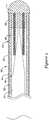
- Figure 1is a plan view of an example medical device 10, for example a guidewire, disposed in a blood vessel 12.
- Guidewire 10may include a distal section 14 that may be generally configured for use within the anatomy of a patient.
- Guidewire 10may be used for intravascular procedures according to common practice and procedure.
- guidewire 10may be used in conjunction with another medical device 16, which may take the form of a catheter, to treat and/or diagnose a medical condition.
- another medical device 16which may take the form of a catheter, to treat and/or diagnose a medical condition.
- numerous other usesare known amongst clinicians for guidewires and other similarly configured medical devices.
- guidewire 10may include a core wire 18 and a tubular member 24 disposed over at least a portion of core wire 18.
- core wire 18may extend to the distal end of tubular member 24.
- tubular member 24may extend distally beyond the distal end of core wire 18.
- a sheath or covering 22may be disposed over portions or all of core wire 18 and/or tubular member 24 that may define a generally smooth outer surface for guidewire 10. In other embodiments, however, such a sheath or covering 22 may be absent from a portion of all of guidewire 10, such that tubular member 24 and/or core wire 18 may form the outer surface.
- a coil 46may be disposed adjacent to core wire 18 and/or tubular member 24.
- the sheath or covering 22is partially cut away to show a side view of core wire 18 and tubular member 24.
- a rounded or generally atraumatic distal tip 11can be formed at the distal end of guidewire 10.
- Core wire 18may extend to and/or into distal tip 11, or may end proximally thereof.
- tubular member 24is attached to core wire 18.
- tubular member 24 and core wire 18can be attached at the proximal end of tubular member 24, the distal end of tubular member 24, both, and/or at any suitable position therebetween.
- FIG. 10depicts another example medical device 10' as a catheter having a catheter shaft 54.
- the proximal end of shaft 54may include a proximal hub 56.
- Hub 56may include a strain relief 60.
- the distal end of shaft 54may include a distal tip region 58 which may take any number of forms.
- Catheter shaft 54may include tubular member 24', which may be similar to other tubular members disclosed herein including tubular member 24.
- a plurality of slots 26'may be formed in tubular member 24'. Slots 26' may be similar to slots 26 (described below) or any other slots described herein.
- Tubular member 24'may extend along any portion or all of catheter shaft 54.
- Catheter 10'may also include any of the features described in U.S. Patent No. 7,001,369 .
- tubular member 24includes a plurality of slots 26 formed therein that extend between the outer surface 30 and the inner surface 31 of tubular member 24.
- Slots 26may be micromachined or otherwise created in tubular member 24, and may be configured to make tubular member 24 more flexible in bending. It is worth noting that, to the extent applicable, the methods for forming slots 26 can include, for example, any of the appropriate micromachining methods and other cutting methods disclosed in U.S. Pat. Publication Nos. US 2003/0069522 and US 2004 0181174 A2 , and/or U.S. Pat. Nos. 6,766,720 and 6,579,246 .
- These and other cutting methodsmay also include saw cutting (e.g., diamond grit embedded semiconductor dicing blade), etching (for example using the etching process described in U.S. Pat. No. 5,106,455 ), laser cutting, electron discharge machining, or the like. It should be noted that the methods for manufacturing guidewire 10 may include forming slots 26 in tubular member 24 using any of these or other manufacturing steps.
- slots 26may be generally arranged to be perpendicular to the longitudinal axis of tubular member 24. This arrangement can, alternatively, be described as having slots 26 lying within a plane that is normal to the longitudinal axis of tubular member 24. In other embodiments, slots 26 may be formed at an angle relative to a plane that is normal to the longitudinal axis. In some embodiments, slots 26 may be formed part way through tubular member 24, while in other embodiments, slots 26 may extend all the way through tubular member 24. Any one or more of the individual slots 26 may extend only partially around the longitudinal axis of tubular member 24.
- slots 26may extend in a helical arrangement about the longitudinal axis of tubular member 24. Slots 26 may be formed in groups of two, three, or more slots 26, which may be located at substantially the same location along the axis of tubular member 24, and may be substantially perpendicular to the longitudinal axis.
- the distribution and/or configuration of slots 24can also include, to the extent applicable, any of those disclosed in U.S. Pat. Publication No. US 2004/0181174 .
- Slots 26may be disposed in tubular member 24 with at least some of these design considerations in mind.
- Figure 3shows a portion of tubular member 24, here it can be seen that slots 26 may have an oval or elliptical shape.
- slots 26may also be formed in tubular member 24 in a manner such that slots 26 have a different geometry or shape at the outside surface 30 of tubular member 24 than at the inside surface 31 (best seen in Figure 3A ) of tubular member 24.
- slots 26may have a first geometry or shape 28a along the outer surface 30 and a second geometry or shape 28b along the inner surface 31.
- first geometry 28a and second geometry 28bare different sizes of the same shape.
- first geometry 28a and second geometry 28bare geometrically similar - i.e., are different sizes of the same shape. This may be true even if the curves or arcs that formed the oval, ellipse, or other closed figure are different due to the different sizes of the objects.
- the intentionis that the geometry of slots 26 is different between outer surface 30 and inner surface 31 in at least some tangible way including, for example, a change in size and/or a change in shape.
- This notationis not intended to mean that geometries 28a/28b are necessarily different geometric forms (e.g., circle versus square) even though these types of arrangements are contemplated.
- some embodiments of tubular members 24include slots 26 that have a different shape altogether (e.g., circle versus square) along outer surface 30 than along inner surface 31.
- tubular member 24includes a bevel or beveled region 27 where the first geometry 28a transitions to the second geometry 28b (see also Figures 3A-3B ).
- Bevel 27may be disposed at essentially any suitable angle relative to outer surface 30.
- bevel 27is disposed at a changing or variable angle.
- bevel 27is a structural element of tubular member 24 where first geometry 28a changes to second geometry 28b.
- Forming slots 26may include the use of a suitable cutting device that includes a blade 32.
- Blade 32includes a cutting surface 34 that is designed to create the desired shape and/or configuration for slots 26.
- blade 32may include a rounded or curved cutting surface 34 that can form the oval slots 26 in tubular member 24.
- the arced shape of cutting surface 34may also be configured to form bevel 27.
- blade 32may form slots 26 such that the width of slot 26 along inner surface 31 is smaller than the width of slot 26 along outer surface 30.
- Thismay provide tubular member 24 with a number of desirable features.
- some slot 26 geometries and/or configurationsmay provide better fatigue life versus stiffness, better axial stiffness versus bending stiffness ratios, better torsional versus bending stiffness ratios, etc. than other slot shapes and/or configurations.
- the geometry and/or configuration of slots 26may be chosen to reduce machining and/or cutting time by reducing the number of features incorporated into tubular member 24 per unit length.
- slots 26may be wider along outer surface 30, fewer slots 26 may be needed to produce a tubular member 24 having the desired properties (e.g., flexibility, torsional rigidity, etc.).
- blade 32can form slots 26 so that they have a width along outer surface 30 that is has about one tenth or more of the length of the outer diameter of tubular member 24.
- the width of slots 26 along inner surface 31may be about one tenth or less of the length of the outer diameter of tubular member 24.
- slots 26may be oval.
- the depiction of slots 26 as being ovalis not intended to be limiting as several other shapes are contemplated.
- Figure 5illustrates a portion of tubular member 124 having slots 126 with a half-moon shape.
- the phrase "half-moon" shapemay termed crescent shaped, semi-circular, semi-oval, etc. without departing from the scope of the invention.
- slots 126have first geometry or shape 128a along the outer surface 130 of tubular member 124 and second geometry or shape 128b along the inner surface.
- Forming slots 126may include the use of blade 132 having cutting surface 134.
- Cutting surface 134may have a wedge-like shape or appearance.
- slots 126can also vary.
- Figure 5illustrates that slots 126 may be sequentially disposed along the longitudinally axis of tubular member 124.
- a series of slotse.g., a first slot 126 and a second slot 126'
- Figure 7illustrates another example tubular member 224 where subsequent slots (e.g., a first slots 226 and a second slot 226') are reverse such that the arched portions of slots 226/126' are on opposite sides.
- Tubular member 324includes slots 326 that are diamond shaped. Slots 326 include bevel 327 that dictates that slots 326 have first geometry or shape 328a at the outer surface 330 of tubular member 324 and second geometry or shape 328b at the inner surface. Forming slots 326 may include the use of blade 332 having cutting surface 334. Cutting surface 334 may have a pointed shape, for example.
- guidewire 10The materials that can be used for the various components of guidewire 10 may include those commonly associated with medical devices. It should be noted that any discussion related to a particular core wire (e.g., core wire 18), tubular member (e.g., tubular member 24), sheath (e.g., sheath 22), or any other component of a guidewire (e.g., guidewire 10) may also hold true for other core wires, tubular members, etc. disclosed herein.
- core wire 18 and/or tubular member 24may be made from a metal, metal alloy, a metal-polymer composite, combinations thereof, and the like, or any other suitable material.
- suitable metals and metal alloysinclude stainless steel, such as 304V, 304L, and 316LV stainless steel; mild steel; nickel-titanium alloy such as linear-elastic and/or super-elastic nitinol; other nickel alloys such as nickel-chromium-molybdenum alloys (e.g., UNS: N06625 such as INCONEL® 625, UNS: N06022 such as HASTELLOY® C-22®, UNS: N10276 such as HASTELLOY® C276®, other HASTELLOY® alloys, and the like), nickel-copper alloys (e.g., UNS: N04400 such as MONEL® 400, NICKELVAC® 400, NICORROS® 400, and the like), nickel-cobalt-chromium-molybdenum alloys (e.g., UNS: R30035 such as MP35-N® and the like), nickel-molybdenum alloys (e.g.,
- Linear elastic and/or non-super-elastic nitinolmay be distinguished from super elastic nitinol in that the linear elastic and/or non-super-elastic nitinol does not display a substantial "superelastic plateau” or “flag region” in its stress/strain curve like super elastic nitinol does.
- linear elastic and/or non-super-elastic nitinolas recoverable strain increases, the stress continues to increase in a substantially linear, or a somewhat, but not necessarily entirely linear relationship until plastic deformation begins or at least in a relationship that is more linear that the super elastic plateau and/or flag region that may be seen with super elastic nitinol.
- linear elastic and/or non-super-elastic nitinolmay also be termed "substantially" linear elastic and/or non-super-elastic nitinol.
- linear elastic and/or non-super-elastic nitinolmay also be distinguishable from super elastic nitinol in that linear elastic and/or non-super-elastic nitinol may accept up to about 2-5% strain while remaining substantially elastic (e.g., before plastically deforming) whereas super elastic nitinol may accept up to about 8% strain before plastically deforming. Both of these materials can be distinguished from other linear elastic materials such as stainless steel (that can also can be distinguished based on its composition), which may accept only about 0.2-0.44% strain before plastically deforming.
- the linear elastic and/or non-super-elastic nickel- titanium alloyis an alloy that does not show any martens ite/austenite phase changes that are detectable by DSC and DMTA analysis over a large temperature range.
- the mechanical bending properties of such materialmay therefore be generally inert to the effect of temperature over this very broad range of temperature.
- the mechanical bending properties of the linear elastic and/or non-super-elastic nickel- titanium alloy at ambient or room temperatureare substantially the same as the mechanical properties at body temperature, for example, in that they do not display a super-elastic plateau and/or flag region.
- the linear elastic and/or non-super-elastic nickel-titanium alloymaintains its linear elastic and/or non-super-elastic characteristics and/or properties and has essentially no yield point.
- the linear elastic and/or non-super-elastic nickel- titanium alloymay be in the range of about 50 to about 60 weight percent nickel, with the remainder being essentially titanium. In some embodiments, the composition is in the range of about 54 to about 57 weight percent nickel.
- a suitable nickel-titanium alloyis FHP-NT alloy commercially available from Furukawa Techno Material Co. of Kanagawa, Japan. Some examples of nickel titanium alloys are disclosed in U.S. Patent Nos. 5,238,004 and 6,508,803 . Other suitable materials may include ULTANIUMTM (available from Neo-Metrics) and GUM METALTM (available from Toyota).
- a superelastic alloyfor example a superelastic nitinol can be used to achieve desired properties.
- portions or all of core wire 18 and/or tubular member 24may also be doped with, made of, or otherwise include a radiopaque material.
- Radiopaque materialsare understood to be materials capable of producing a relatively bright image on a fluoroscopy screen or another imaging technique during a medical procedure. This relatively bright image aids the user of device 10 in determining its location.
- Some examples of radiopaque materialscan include, but are not limited to, gold, platinum, palladium, tantalum, tungsten alloy, polymer material loaded with a radiopaque filler, and the like. Additionally, radiopaque marker bands and/or coils may be incorporated into the design of guidewire 10 to achieve the same result.
- a degree of MRI compatibilityis imparted into device 10.
- core wire 18 and/or tubular member 24, or other portions of the medical device 10may be made of a material that does not substantially distort the image and create substantial artifacts (artifacts are gaps in the image). Certain ferromagnetic materials, for example, may not be suitable because they may create artifacts in an MRI image.
- Core wire 18 and/or tubular member 24, or portions thereofmay also be made from a material that the MRI machine can image.
- Some materials that exhibit these characteristicsinclude, for example, tungsten, cobalt-chromium-molybdenum alloys (e.g., UNS: R30003 such as ELGILOY®, PHYNOX®, and the like), nickel-cobalt-chromium-molybdenum alloys (e.g., UNS: R30035 such as MP35-N® and the like), nitinol, and the like, and others.
- cobalt-chromium-molybdenum alloyse.g., UNS: R30003 such as ELGILOY®, PHYNOX®, and the like
- nickel-cobalt-chromium-molybdenum alloyse.g., UNS: R30035 such as MP35-N® and the like
- nitinoland the like, and others.
- the entire core wire 18can be made of the same material along its length, or in some embodiments, can include portions or sections made of different materials.
- the material used to construct core wire 18is chosen to impart varying flexibility and stiffness characteristics to different portions of core wire 18.
- the proximal region and the distal region of core wire 18may be formed of different materials, for example materials having different moduli of elasticity, resulting in a difference in flexibility.
- the material used to construct the proximal regioncan be relatively stiff for pushability and torqueability, and the material used to construct the distal region can be relatively flexible by comparison for better lateral trackability and steerability.
- the proximal regioncan be formed of straightened 304v stainless steel wire or ribbon and the distal region can be formed of a straightened super elastic or linear elastic alloy, for example a nickel-titanium alloy wire or ribbon.
- the different portionscan be connected using any suitable connecting techniques.
- the different portions of core wire 18can be connected using welding (including laser welding), soldering, brazing, adhesive, or the like, or combinations thereof.
- some embodimentscan include one or more mechanical connectors or connector assemblies to connect the different portions of core wire 18 that are made of different materials.
- the connectormay include any structure generally suitable for connecting portions of a guidewire.
- a suitable structureincludes a structure such as a hypotube or a coiled wire which has an inside diameter sized appropriately to receive and connect to the ends of the proximal portion and the distal portion.
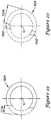
- Core wire 18can have a solid cross-section, but in some embodiments, can have a hollow cross-section. In yet other embodiments, core wire 18 can include a combination of areas having solid cross-sections and hollow cross sections. Moreover, core wire 18, or portions thereof, can be made of rounded wire, flattened ribbon, or other such structures having various cross-sectional geometries. The cross- sectional geometries along the length of core wire 18 can also be constant or can vary. For example, Figure 2 depicts core wire 18 as having a round cross-sectional shape. It can be appreciated that other cross-sectional shapes or combinations of shapes may be utilized without departing from the scope of the invention. For example, the cross- sectional shape of core wire 18 may be oval, rectangular, square, polygonal, and the like, or any suitable shape.
- Sheath 22may be made from a polymer or any other suitable material.
- suitable polymersmay include polytetrafluoroethylene (PTFE), ethylene tetrafluoroethylene (ETFE), fluorinated ethylene propylene (FEP), polyoxymethylene (POM, for example, DELRIN® available from DuPont), polyether block ester, polyurethane, polypropylene (PP), polyvinylchloride (PVC), polyether-ester (for example, ARNITEL® available from DSM Engineering Plastics), ether or ester based copolymers (for example, butylene/poly(alkylene ether) phthalate and/or other polyester elastomers such as HYTREL® available from DuPont), polyamide (for example, DURETHAN® available from Bayer or CRISTAMID® available from Elf Atochem), elastomeric polyamides, block polyamide/ethers, polyether block amide (PEBA, for example available under the trade name PEBAX
- sheath 22can be blended with a liquid crystal polymer (LCP).
- LCPliquid crystal polymer
- the mixturecan contain up to about 6% LCP. This has been found to enhance torqueability.
- the exterior surface of the guidewire 10may be sandblasted, beadblasted, sodium bicarbonate-blasted, electropolished, etc.
- a coatingfor example a lubricious, a hydrophilic, a protective, or other type of coating may be applied over portions or all of sheath 22, or in embodiments without a sheath 22 over portion of core wire 18 and/or tubular member, or other portions of device 10.
- sheath 22may comprise a lubricious, hydrophilic, protective, or other type of coating.
- Hydrophobic coatingssuch as fluoropolymers provide a dry lubricity which improves guidewire handling and device exchanges.
- Lubricious coatingsimprove steerability and improve lesion crossing capability.
- Suitable lubricious polymersare well known in the art and may include silicone and the like, hydrophilic polymers such as high-density polyethylene (HDPE), polytetrafluoroethylene (PTFE), polyarylene oxides, polyvinylpyrolidones, polyvinylalcohols, hydroxy alkyl cellulosics, algins, saccharides, caprolactones, and the like, and mixtures and combinations thereof.
- HDPEhigh-density polyethylene
- PTFEpolytetrafluoroethylene
- polyarylene oxidespolyvinylpyrolidones
- polyvinylalcoholspolyvinylalcohols
- hydroxy alkyl cellulosicsalgins
- Hydrophilic polymersmay be blended among themselves or with formulated amounts of water insoluble compounds (including some polymers) to yield coatings with suitable lubricity, bonding, and solubility.
- Some other examples of such coatings and materials and methods used to create such coatingscan be found in U.S. Patent Nos. 6,139,510 and 5,772,609 .
- the coating and/or sheath 22may be formed, for example, by coating, extrusion, co-extrusion, interrupted layer co-extrusion (ILC), or fusing several segments end-to-end.
- the layermay have a uniform stiffness or a gradual reduction in stiffness from the proximal end to the distal end thereof. The gradual reduction in stiffness may be continuous as by ILC or may be stepped as by fusing together separate extruded tubular segments.
- the outer layermay be impregnated with a radiopaque filler material to facilitate radiographic visualization. Those skilled in the art will recognize that these materials can vary widely without deviating from the scope of the present invention.
- Figures 10-20depict a variety of example tubular members and cuts formed in the example tubular members in order to illustrate some addition variations contemplated for the distribution of slots in a tubular member.
- similar reference numbersare used throughout these figures.
- several different tubular membermay be formed or defined according to the forgoing description including several that may be utilized in any of the devices and/or guidewire disclosed herein.
- the description of these figuresmake use of the words "beam” and/or "beams”.
- the beamsare the portion of the tubular member, often resembling a beam in appearance, that remains after cutting away a portion of the tubular member to form the slots.
- FIG 10is a perspective view of an example tubular member 424, here it can be generally seen how slots 426 may be distributed along tubular member 424 as well as how beams 448 are located between slots 426.
- Figure 11when a cutting member or blade cuts into tubular member 424 to form slots, the blade slice through tubular member 424 at a particular angular position (e.g., for convenience sake assume the angular position is located at the right hand side or the 0° position of tubular member 424) to a position called the cut depth CD and defines a slot 426 (depicted in phantom as the portion of tubular member 424 removed by cutting).
- the beam height BHis the length of width of the beam in the radial direction.
- the beam height BHmay be related to the cut depth CD and the outer diameter OD of tubular member 424. For example, in at least some cases the "deeper” the cut depth CD, the "shorter” the beam height BH.
- tubular member 424may be made at the same longitudinal position (e.g., from the opposite angular position (e.g., 180°) of tubular member 424 as shown in Figure 12 .
- a second slot 426'is formed.
- the second cutform a pair of slots 426/426', a pair of beams 448/448' are defined.
- additional pairs of slots and beamscan be formed by making additional cuts.
- the cutscan be from the same position (e.g., from the 0° and the 180° positions of tubular member 424).
- the cutscan begin from a different angular position.
- the first cut made in tubular member 424 at a subsequent longitudinal positionmay be rotated a radial distance or angle A from where the first cut was made at the first longitudinal position.
- Angle Acould be any suitable angle such as, for example, about 60-120° or about 85° as shown in Figure 13 .
- Another cut from the opposite side of tubular member 424defines a second pair of beams 450/450'. At other longitudinal positions, cuts can be rotated to the same extent or to different extents.
- all the beam pairs 448/448' and/or 450/450'all have centers that align with the tube centerline C (i.e., a line drawn between the middle of opposing pairs of beams goes through the tube centerline C). While this can be desirable in some embodiments, other arrangements are contemplated that include beam centers that are offset from the tube centerline C to create structures with lower bending stiffness.
- Figure 14depicts tubular member 424' where beam pairs 448/448' and beam pairs 450/450' are rotated 90° relative to one another. Beams 448/448' are aligned with the tube centerline C. However, beams 450/450' are offset a distance D from the tube centerline C.
- Arrangements like thismay result in a tubular member that is anisotrophic (i.e., soft in bending in one plane relative to other planes).
- Other arrangementsare contemplated where both beams 448/448' and beams 450/450' are offset from the tube centerline C. The amount of offset may or may not be the same.
- the beam pairsmay or may not be rotated around the circumference of tubular member 424' at any suitable angle. Embodiments where the offsets are the same and the angle is fixed may result in a tubular member that is isotrophic.
- FIG. 15the cross-section of another example tubular member 524 is shown that can be used in any of the device described herein.
- the structure of tubular member 524includes a slot/beam arrangement wherein the amount or distance of the beam offset varies as a function of the angular position from which the cut defining the slot/beam originates from.
- CD1is the first cut in a pair of cuts that creates a pair of beams.
- CD2is the second cut in a pair of cuts that creates a pair of beams.
- the MAXOFFSETis the maximum desired beam centerline offset, which can be fixed as any suitable distance.
- the ANGULARPOSITIONis the angle from which the blade approaches the tube centerline C to make a given cut.
- the beam centerline for this pair of beams 550/550'would be 0.0872* MAXOFFSET units from the tube centerline C, toward the 265° position.
- the next cutwould come from 85° (position of last cut) + 85° (helix angle) or 170°.
- the next cutwould come from 170° +180° or 350°.
- the beam centerline for this pair of beams 552/552'would be shifted .9848* MAXOFFSET units from the tube centerline, toward the 170° direction.
- the beam-tube centerline offset for beam pairs at other angleswill be distributed via the Cosine function between 0 and MAXOFFSET units. It can be appreciated that a similar strategy can be utilized using different functions (e.g., Sine, Tangent, etc.)
Landscapes
- Health & Medical Sciences (AREA)
- Life Sciences & Earth Sciences (AREA)
- Engineering & Computer Science (AREA)
- Veterinary Medicine (AREA)
- Biomedical Technology (AREA)
- Heart & Thoracic Surgery (AREA)
- Animal Behavior & Ethology (AREA)
- General Health & Medical Sciences (AREA)
- Public Health (AREA)
- Biophysics (AREA)
- Surgery (AREA)
- Pulmonology (AREA)
- Anesthesiology (AREA)
- Hematology (AREA)
- Nuclear Medicine, Radiotherapy & Molecular Imaging (AREA)
- Optics & Photonics (AREA)
- Pathology (AREA)
- Radiology & Medical Imaging (AREA)
- Physics & Mathematics (AREA)
- Medical Informatics (AREA)
- Molecular Biology (AREA)
- Manufacturing & Machinery (AREA)
- Materials For Medical Uses (AREA)
- Media Introduction/Drainage Providing Device (AREA)
Description
- The present invention pertains to intracorporal medical devices, for example, intravascular guidewires, catheters, and the like as well as improved methods for manufacturing medical devices. More particularly, the invention relates to medical devices including a tubular member having a plurality of slots formed therein.
- A wide variety of intracorporeal medical devices have been developed for medical use, for example, intravascular use. Some of these devices include guidewires, catheters, and the like. Of the known medical devices, each has certain advantages and disadvantages. There is an ongoing need to provide alternative medical devices as well as alternative methods for manufacturing and using medical devices.
US 2006/0189896 discloses a medical device according to the preamble of claim 1. In particular, this known device is for guiding through anatomy, such as a catheter or guidewire, with a tubular body that has been slotted to enhance bending flexibility, and a polymer liner with an anti-collapsing structure, and a method of making a medical device with a kink-resistant corrugated tubular member and an anti-collapsing structure. Anti collapsing structures may be helical or annular, and may be wire, such as ribbon wire, grooves in the liner, corrugations, or a braid. Liners may be bonded to the anti-collapsing structure, or may have two layers, with the anti-collapsing structure between the layers. Corrugations may be formed between sections of the anti-collapsing 'structure with heat, pressure, stretching, compression, a mold, or a combination thereof, and may extend inward or outward. Shape or wall thickness may vary along the length to provide a varying bending stiffness. Slots may be formed in groups of two, three, or more, and adjacent groups may be rotated about the axis forming a helical pattern.- The invention is defined by the features of the claims.
- The invention provides design, material, and manufacturing method alternatives for medical devices. An example medical device includes a tubular member having a plurality of slots formed therein. The slots can be arranged and/or configured in a number of different ways. Some of these and other features and characteristics of the inventive devices and methods are described in more detail below.
- The above summary of some embodiments is not intended to describe each disclosed embodiment or every implementation of the present invention. The Figures, and Detailed Description, which follow, more particularly exemplify these embodiments.
- The invention may be more completely understood in consideration of the following detailed description of various embodiments of the invention in connection with the accompanying drawings, in which:
Figure 1 is a plan view of an example medical device disposed in a blood vessel;Figure 2 is a partially cut-away side view of an example medical device;Figure 2A is a partially cut-away side view of another example medical device;Figure 3 illustrates a portion of an example tubular member;Figure 3 A is a cross-sectional view of the tubular member depicted inFigure 3 ;Figure 3B is an alternate cross-sectional view of the tubular member depicted inFigure 3 ;Figure 4 illustrates a portion of an example cutting blade;Figure 5 illustrates a portion of another example tubular member;Figure 6 illustrates a portion of another example cutting blade;Figure 7 illustrates a portion of another example tubular member;Figure 8 illustrates a portion of another example tubular member;Figure 9 illustrates a portion of another example cutting blade;Figure 10 is a perspective view of a portion of another example tubular member;Figure 11 is a cross-sectional view depicting an example tubular member and cuts that can be utilized to form slots in the tubular member;Figure 12 is a cross-sectional view taken through line 12 - 12 inFigure 10 ;Figures 13-20 are cross-sectional views depicting example tubular members and various cuts that can be utilized to form slots in the tubular members.- While the invention is amenable to various modifications and alternative forms, specifics thereof have been shown by way of example in the drawings and will be described in detail. It should be understood, however, that the intention is not to limit the invention to the particular embodiments described. On the contrary, the intention is to cover all modifications, equivalents, and alternatives falling within the scope of the appended claims.
- For the following defined terms, these definitions shall be applied, unless a different definition is given in the claims or elsewhere in this specification.
- All numeric values are herein assumed to be modified by the term "about," whether or not explicitly indicated. The term "about" generally refers to a range of numbers that one of skill in the art would consider equivalent to the recited value (i.e., having the same function or result). In many instances, the terms "about" may include numbers that are rounded to the nearest significant figure.
- The recitation of numerical ranges by endpoints includes all numbers within that range (e.g. 1 to 5 includes 1, 1.5, 2, 2.75, 3, 3.80, 4, and 5).
- As used in this specification and the appended claims, the singular forms "a", "an", and "the" include plural referents unless the content clearly dictates otherwise. As used in this specification and the appended claims, the term "or" is generally employed in its sense including "and/or" unless the content clearly dictates otherwise.
- The following detailed description should be read with reference to the drawings in which similar elements in different drawings are numbered the same. The drawings, which are not necessarily to scale, depict illustrative embodiments and are not intended to limit the scope of the invention.
Figure 1 is a plan view of an examplemedical device 10, for example a guidewire, disposed in ablood vessel 12. Guidewire 10 may include adistal section 14 that may be generally configured for use within the anatomy of a patient. Guidewire 10 may be used for intravascular procedures according to common practice and procedure. For example,guidewire 10 may be used in conjunction with another medical device 16, which may take the form of a catheter, to treat and/or diagnose a medical condition. Of course, numerous other uses are known amongst clinicians for guidewires and other similarly configured medical devices.- Turning now to
Figure 2 ,distal section 14 ofguidewire 10 is illustrated. Here it can be seen thatguidewire 10 may include acore wire 18 and atubular member 24 disposed over at least a portion ofcore wire 18. In some embodiments,core wire 18 may extend to the distal end oftubular member 24. In other embodiments,tubular member 24 may extend distally beyond the distal end ofcore wire 18. A sheath or covering 22 may be disposed over portions or all ofcore wire 18 and/ortubular member 24 that may define a generally smooth outer surface forguidewire 10. In other embodiments, however, such a sheath or covering 22 may be absent from a portion of all ofguidewire 10, such thattubular member 24 and/orcore wire 18 may form the outer surface. Acoil 46 may be disposed adjacent tocore wire 18 and/ortubular member 24. InFigure 2 , the sheath or covering 22 is partially cut away to show a side view ofcore wire 18 andtubular member 24. A rounded or generally atraumaticdistal tip 11 can be formed at the distal end ofguidewire 10.Core wire 18 may extend to and/or intodistal tip 11, or may end proximally thereof. In some embodiments,tubular member 24 is attached tocore wire 18. For example,tubular member 24 andcore wire 18 can be attached at the proximal end oftubular member 24, the distal end oftubular member 24, both, and/or at any suitable position therebetween. Some additional description regarding the attachment of core wires and tubular members can be found inU.S. Patent Pub. No. 2004/0181174-A2 . It should be noted that although some of the discussion herein is directed to embodiments wheremedical device 10 is a guidewire, this is not intended to be limiting. It can be appreciated that numerous alternative embodiments are contemplated wheredevice 10 is another device such as a catheter (including guide catheters, balloon catheters, etc.), endoscopic device, laparoscopic device, and the like or any other suitable guiding, diagnosing, or treating device that be suitable for use at essentially any location and/or body lumen within a patient. For example,Figure 2A depicts another example medical device 10' as a catheter having acatheter shaft 54. The proximal end ofshaft 54 may include aproximal hub 56.Hub 56 may include astrain relief 60. The distal end ofshaft 54 may include adistal tip region 58 which may take any number of forms.Catheter shaft 54 may include tubular member 24', which may be similar to other tubular members disclosed herein includingtubular member 24. A plurality of slots 26' may be formed in tubular member 24'. Slots 26' may be similar to slots 26 (described below) or any other slots described herein. Tubular member 24' may extend along any portion or all ofcatheter shaft 54. Catheter 10' may also include any of the features described inU.S. Patent No. 7,001,369 . - Turning back now to
Figure 2 , as indicated abovetubular member 24 includes a plurality ofslots 26 formed therein that extend between theouter surface 30 and theinner surface 31 oftubular member 24.Slots 26 may be micromachined or otherwise created intubular member 24, and may be configured to maketubular member 24 more flexible in bending. It is worth noting that, to the extent applicable, the methods for formingslots 26 can include, for example, any of the appropriate micromachining methods and other cutting methods disclosed in U.S. Pat. Publication Nos.US 2003/0069522 andUS 2004 0181174 A2 ,
and/orU.S. Pat. Nos. 6,766,720 and6,579,246 . These and other cutting methods may also include saw cutting (e.g., diamond grit embedded semiconductor dicing blade), etching (for example using the etching process described inU.S. Pat. No. 5,106,455 ), laser cutting, electron discharge machining, or the like. It should be noted that the methods formanufacturing guidewire 10 may include formingslots 26 intubular member 24 using any of these or other manufacturing steps. - Various embodiments of arrangements and configurations of
slots 26 are contemplated.Slots 26 may be generally arranged to be perpendicular to the longitudinal axis oftubular member 24. This arrangement can, alternatively, be described as havingslots 26 lying within a plane that is normal to the longitudinal axis oftubular member 24. In other embodiments,slots 26 may be formed at an angle relative to a plane that is normal to the longitudinal axis. In some embodiments,slots 26 may be formed part way throughtubular member 24, while in other embodiments,slots 26 may extend all the way throughtubular member 24. Any one or more of theindividual slots 26 may extend only partially around the longitudinal axis oftubular member 24. In yet other embodiments,slots 26 may extend in a helical arrangement about the longitudinal axis oftubular member 24.Slots 26 may be formed in groups of two, three, ormore slots 26, which may be located at substantially the same location along the axis oftubular member 24, and may be substantially perpendicular to the longitudinal axis. The distribution and/or configuration ofslots 24 can also include, to the extent applicable, any of those disclosed in U.S. Pat. Publication No.US 2004/0181174 . Slots 26 may be disposed intubular member 24 with at least some of these design considerations in mind. Turning now toFigure 3 , which shows a portion oftubular member 24, here it can be seen thatslots 26 may have an oval or elliptical shape. In addition to having this shape,slots 26 may also be formed intubular member 24 in a manner such thatslots 26 have a different geometry or shape at theoutside surface 30 oftubular member 24 than at the inside surface 31 (best seen inFigure 3A ) oftubular member 24. For example,slots 26 may have a first geometry orshape 28a along theouter surface 30 and a second geometry or shape 28b along theinner surface 31. It should be noted that numerous geometries/shapes are contemplated outside of what is shown, including circles, triangles, squares,
rectangles, parallelograms, rhombuses, trapezoids, polygons (including polygons having essentially any number of sides), regular-shaped objects, irregularly shaped objects, star shapes, letter shapes (e.g., "U" shaped, "L" shaped, etc.), or any other suitable shape.- In some embodiments,
first geometry 28a andsecond geometry 28b are different sizes of the same shape. Thus,first geometry 28a andsecond geometry 28b are geometrically similar - i.e., are different sizes of the same shape. This may be true even if the curves or arcs that formed the oval, ellipse, or other closed figure are different due to the different sizes of the objects. The intention is that the geometry ofslots 26 is different betweenouter surface 30 andinner surface 31 in at least some tangible way including, for example, a change in size and/or a change in shape. This notation, however, is not intended to mean thatgeometries 28a/28b are necessarily different geometric forms (e.g., circle versus square) even though these types of arrangements are contemplated. Thus, some embodiments oftubular members 24 includeslots 26 that have a different shape altogether (e.g., circle versus square) alongouter surface 30 than alonginner surface 31. - Between the outer and
inner surfaces 30/31,tubular member 24 includes a bevel orbeveled region 27 where thefirst geometry 28a transitions to thesecond geometry 28b (see alsoFigures 3A-3B ).Bevel 27 may be disposed at essentially any suitable angle relative toouter surface 30. In addition,bevel 27 is disposed at a changing or variable angle. Thus,bevel 27 is a structural element oftubular member 24 wherefirst geometry 28a changes tosecond geometry 28b. - Forming
slots 26 may include the use of a suitable cutting device that includes ablade 32.Blade 32 includes a cuttingsurface 34 that is designed to create the desired shape and/or configuration forslots 26. For example,blade 32 may include a rounded orcurved cutting surface 34 that can form theoval slots 26 intubular member 24. In addition, the arced shape of cuttingsurface 34 may also be configured to formbevel 27. - In can be appreciated that
blade 32 may formslots 26 such that the width ofslot 26 alonginner surface 31 is smaller than the width ofslot 26 alongouter surface 30. This may providetubular member 24 with a number of desirable features. For example, someslot 26 geometries and/or configurations may provide better fatigue life versus stiffness, better axial stiffness versus bending stiffness ratios, better torsional versus bending stiffness ratios, etc. than other slot shapes and/or configurations. In addition, the geometry and/or configuration ofslots 26 may be chosen to reduce machining and/or cutting time by reducing the number of features incorporated intotubular member 24 per unit length. For example, becauseslots 26 may be wider alongouter surface 30,fewer slots 26 may be needed to produce atubular member 24 having the desired properties (e.g., flexibility, torsional rigidity, etc.). In at least some embodiments,blade 32 can formslots 26 so that they have a width alongouter surface 30 that is has about one tenth or more of the length of the outer diameter oftubular member 24. Conversely, the width ofslots 26 alonginner surface 31 may be about one tenth or less of the length of the outer diameter oftubular member 24. - As described above in relation to
Figure 3 ,slots 26 may be oval. However, the depiction ofslots 26 as being oval is not intended to be limiting as several other shapes are contemplated. For example,Figure 5 illustrates a portion oftubular member 124 havingslots 126 with a half-moon shape. It should be noted that the phrase "half-moon" shape may termed crescent shaped, semi-circular, semi-oval, etc. without departing from the scope of the invention. Just likeslots 26, because ofbevel 127,slots 126 have first geometry orshape 128a along theouter surface 130 oftubular member 124 and second geometry orshape 128b along the inner surface. Formingslots 126 may include the use ofblade 132 havingcutting surface 134. Cuttingsurface 134 may have a wedge-like shape or appearance. - The arrangement of
slots 126 can also vary. For example,Figure 5 illustrates thatslots 126 may be sequentially disposed along the longitudinally axis oftubular member 124. For example, a series of slots (e.g., afirst slot 126 and a second slot 126') are sequentially disposed such that arched portions ofslots 126/126' are on the same side.Figure 7 illustrates anotherexample tubular member 224 where subsequent slots (e.g., afirst slots 226 and a second slot 226') are reverse such that the arched portions ofslots 226/126' are on opposite sides. - A portion of another
example tubular member 324 is shown inFigure 8 .Tubular member 324 includesslots 326 that are diamond shaped.Slots 326 includebevel 327 that dictates thatslots 326 have first geometry orshape 328a at theouter surface 330 oftubular member 324 and second geometry orshape 328b at the inner surface. Formingslots 326 may include the use ofblade 332 havingcutting surface 334. Cuttingsurface 334 may have a pointed shape, for example. - The materials that can be used for the various components of
guidewire 10 may include those commonly associated with medical devices. It should be noted that any discussion related to a particular core wire (e.g., core wire 18), tubular member (e.g., tubular member 24), sheath (e.g., sheath 22), or any other component of a guidewire (e.g., guidewire 10) may also hold true for other core wires, tubular members, etc. disclosed herein. For example,core wire 18 and/or tubular member 24 (and/or other core wires, tubular members, etc. disclosed herein) may be made from a metal, metal alloy, a metal-polymer composite, combinations thereof, and the like, or any other suitable material. Some examples of suitable metals and metal alloys include stainless steel, such as 304V, 304L, and 316LV stainless steel; mild steel; nickel-titanium alloy such as linear-elastic and/or super-elastic nitinol; other nickel alloys such as nickel-chromium-molybdenum alloys (e.g., UNS: N06625 such as INCONEL® 625, UNS: N06022 such as HASTELLOY® C-22®, UNS: N10276 such as HASTELLOY® C276®, other HASTELLOY® alloys, and the like), nickel-copper alloys (e.g., UNS: N04400 such as MONEL® 400, NICKELVAC® 400, NICORROS® 400, and the like), nickel-cobalt-chromium-molybdenum alloys (e.g., UNS: R30035 such as MP35-N® and the like), nickel-molybdenum alloys (e.g., UNS: N10665 such as HASTELLOY® ALLOY B2®), other nickel-chromium alloys, other nickel-molybdenum alloys, other nickel-cobalt alloys, other nickel-iron alloys, other nickel-copper alloys, other nickel-tungsten or tungsten alloys, and the like; cobalt-chromium alloys; cobalt-chromium-molybdenum alloys (e.g., UNS: R30003 such as ELGILOY®, PHYNOX®, and the like); platinum enriched stainless steel; combinations thereof; and the like; or any other suitable material. - As alluded to above, within the family of commercially available nickel-titanium or nitinol alloys, is a category designated "linear elastic" or "non-super-elastic" which, although may be similar in chemistry to conventional shape memory and super elastic varieties, may exhibit distinct and useful mechanical properties. Linear elastic and/or non-super-elastic nitinol may be distinguished from super elastic nitinol in that the linear elastic and/or non-super-elastic nitinol does not display a substantial "superelastic plateau" or "flag region" in its stress/strain curve like super elastic nitinol does. Instead, in the linear elastic and/or non-super-elastic nitinol, as recoverable strain increases, the stress continues to increase in a substantially linear, or a somewhat, but not necessarily entirely linear relationship until plastic deformation begins or at least in a relationship that is more linear that the super elastic plateau and/or flag region that may be seen with super elastic nitinol. Thus, for the purposes of this disclosure linear elastic and/or non-super-elastic nitinol may also be termed "substantially" linear elastic and/or non-super-elastic nitinol.
- In some cases, linear elastic and/or non-super-elastic nitinol may also be distinguishable from super elastic nitinol in that linear elastic and/or non-super-elastic nitinol may accept up to about 2-5% strain while remaining substantially elastic (e.g., before plastically deforming) whereas super elastic nitinol may accept up to about 8% strain before plastically deforming. Both of these materials can be distinguished from other linear elastic materials such as stainless steel (that can also can be distinguished based on its composition), which may accept only about 0.2-0.44% strain before plastically deforming.
- In some embodiments, the linear elastic and/or non-super-elastic nickel- titanium alloy is an alloy that does not show any martens ite/austenite phase changes that are detectable by DSC and DMTA analysis over a large temperature range. For example, in some embodiments, there may be no martensite/austenite phase changes detectable by DSC and DMTA analysis in the range of about -60°C to about 120°C in the linear elastic and/or non-super-elastic nickel-titanium alloy. The mechanical bending properties of such material may therefore be generally inert to the effect of temperature over this very broad range of temperature. In some embodiments, the mechanical bending properties of the linear elastic and/or non-super-elastic nickel- titanium alloy at ambient or room temperature are substantially the same as the mechanical properties at body temperature, for example, in that they do not display a super-elastic plateau and/or flag region. In other words, across a broad temperature range, the linear elastic and/or non-super-elastic nickel-titanium alloy maintains its linear elastic and/or non-super-elastic characteristics and/or properties and has essentially no yield point.
- In some embodiments, the linear elastic and/or non-super-elastic nickel- titanium alloy may be in the range of about 50 to about 60 weight percent nickel, with the remainder being essentially titanium. In some embodiments, the composition is in the range of about 54 to about 57 weight percent nickel. One example of a suitable nickel-titanium alloy is FHP-NT alloy commercially available from Furukawa Techno Material Co. of Kanagawa, Japan. Some examples of nickel titanium alloys are disclosed in
U.S. Patent Nos. 5,238,004 and6,508,803 . Other suitable materials may include ULTANIUM™ (available from
Neo-Metrics) and GUM METAL™ (available from Toyota). In some other embodiments, a superelastic alloy, for example a superelastic nitinol can be used to achieve desired properties. - In at least some embodiments, portions or all of
core wire 18 and/or tubular member 24 (and/or other core wires, tubular members, etc. disclosed herein) may also be doped with, made of, or otherwise include a radiopaque material. Radiopaque materials are understood to be materials capable of producing a relatively bright image on a fluoroscopy screen or another imaging technique during a medical procedure. This relatively bright image aids the user ofdevice 10 in determining its location. Some examples of radiopaque materials can include, but are not limited to, gold, platinum, palladium, tantalum, tungsten alloy, polymer material loaded with a radiopaque filler, and the like. Additionally, radiopaque marker bands and/or coils may be incorporated into the design ofguidewire 10 to achieve the same result. - In some embodiments, a degree of MRI compatibility is imparted into
device 10. For example, to enhance compatibility with Magnetic Resonance Imaging (MRI) machines, it may be desirable to makecore wire 18 and/ortubular member 24, or other portions of themedical device 10, in a manner that would impart a degree of MRI compatibility. For example,core wire 18 and/ortubular member 24, or portions thereof, may be made of a material that does not substantially distort the image and create substantial artifacts (artifacts are gaps in the image). Certain ferromagnetic materials, for example, may not be suitable because they may create artifacts in an MRI image.Core wire 18 and/ortubular member 24, or portions thereof, may also be made from a material that the MRI machine can image. Some materials that exhibit these characteristics include, for example, tungsten, cobalt-chromium-molybdenum alloys (e.g., UNS: R30003 such as ELGILOY®, PHYNOX®, and the like), nickel-cobalt-chromium-molybdenum alloys (e.g., UNS: R30035 such as MP35-N® and the like), nitinol, and the like, and others. - Referring now to
core wire 18, theentire core wire 18 can be made of the same material along its length, or in some embodiments, can include portions or sections made of different materials. In some embodiments, the material used to constructcore wire 18 is chosen to impart varying flexibility and stiffness characteristics to different portions ofcore wire 18. For example, the proximal region and the distal region ofcore wire 18 may be formed of different materials, for example materials having different moduli of elasticity, resulting in a difference in flexibility. In some embodiments, the material used to construct the proximal region can be relatively stiff for pushability and torqueability, and the material used to construct the distal region can be relatively flexible by comparison for better lateral trackability and steerability. For example, the proximal region can be formed of straightened 304v stainless steel wire or ribbon and the distal region can be formed of a straightened super elastic or linear elastic alloy, for example a nickel-titanium alloy wire or ribbon. - In embodiments where different portions of
core wire 18 are made of different materials, the different portions can be connected using any suitable connecting techniques. For example, the different portions ofcore wire 18 can be connected using welding (including laser welding), soldering, brazing, adhesive, or the like, or combinations thereof. Additionally, some embodiments can include one or more mechanical connectors or connector assemblies to connect the different portions ofcore wire 18 that are made of different materials. The connector may include any structure generally suitable for connecting portions of a guidewire. One example of a suitable structure includes a structure such as a hypotube or a coiled wire which has an inside diameter sized appropriately to receive and connect to the ends of the proximal portion and the distal portion. Some other examples of suitable techniques and structures that can be used to interconnect different shaft sections are disclosed inU.S. Patent Application Nos. 09/972,276 filed on October 5, 2001 10/068,992 filed on February 28, 2002 10/375,766 filed on February 26, 2003 Core wire 18 can have a solid cross-section, but in some embodiments, can have a hollow cross-section. In yet other embodiments,core wire 18 can include a combination of areas having solid cross-sections and hollow cross sections. Moreover,core wire 18, or portions thereof, can be made of rounded wire, flattened ribbon, or other such structures having various cross-sectional geometries. The cross- sectional geometries along the length ofcore wire 18 can also be constant or can vary. For example,Figure 2 depictscore wire 18 as having a round cross-sectional shape. It can be appreciated that other cross-sectional shapes or combinations of shapes may be utilized without departing from the scope of the invention. For example, the cross- sectional shape ofcore wire 18 may be oval, rectangular, square, polygonal, and the like, or any suitable shape.Sheath 22 may be made from a polymer or any other suitable material. Some examples of suitable polymers may include polytetrafluoroethylene (PTFE), ethylene tetrafluoroethylene (ETFE), fluorinated ethylene propylene (FEP), polyoxymethylene (POM, for example, DELRIN® available from DuPont), polyether block ester, polyurethane, polypropylene (PP), polyvinylchloride (PVC), polyether-ester (for example, ARNITEL® available from DSM Engineering Plastics), ether or ester based copolymers (for example, butylene/poly(alkylene ether) phthalate and/or other polyester elastomers such as HYTREL® available from DuPont), polyamide (for example, DURETHAN® available from Bayer or CRISTAMID® available from Elf Atochem), elastomeric polyamides, block polyamide/ethers, polyether block amide (PEBA, for example available under the trade name PEBAX®), ethylene vinyl acetate copolymers (EVA), silicones, polyethylene (PE), Marlex high-density polyethylene, Marlex low-density polyethylene, linear low density polyethylene (for example REXELL®), polyester, polybutylene terephthalate (PBT), polyethylene terephthalate (PET), polytrimethylene terephthalate, polyethylene naphthalate (PEN), polyetheretherketone (PEEK), polyimide (PI), polyetherimide (PEI), polyphenylene sulfide (PPS), polyphenylene oxide (PPO), poly paraphenylene terephthalamide (for example, KEVLAR®), polysulfone, nylon, nylon-12 (such as GRILAMID® available from EMS American Grilon), perfluoro(propyl vinyl ether) (PFA), ethylene vinyl alcohol, polyolefin, polystyrene, epoxy, polyvinylidene chloride (PVdC), polycarbonates, ionomers, biocompatible polymers, other suitable materials, or mixtures, combinations, copolymers thereof, polymer/metal composites, and the like. In someembodiments sheath 22 can be blended with a liquid crystal polymer (LCP). For example, the mixture can contain up to about 6% LCP. This has been found to enhance torqueability. By employing selection of materials and processing techniques, thermoplastic, solvent soluble, and thermosetting variants of these and other materials can be employed to achieve the desired results.- In some embodiments, the exterior surface of the guidewire 10 (including, for example, the exterior surface of
core wire 18 and/or the exterior surface of tubular member 24) may be sandblasted, beadblasted, sodium bicarbonate-blasted, electropolished, etc. In these as well as in some other embodiments, a coating, for example a lubricious, a hydrophilic, a protective, or other type of coating may be applied over portions or all ofsheath 22, or in embodiments without asheath 22 over portion ofcore wire 18 and/or tubular member, or other portions ofdevice 10. Alternatively,sheath 22 may comprise a lubricious, hydrophilic, protective, or other type of coating. Hydrophobic coatings such as fluoropolymers provide a dry lubricity which improves guidewire handling and device exchanges. Lubricious coatings improve steerability and improve lesion crossing capability. Suitable lubricious polymers are well known in the art and may include silicone and the like, hydrophilic polymers such as high-density polyethylene (HDPE), polytetrafluoroethylene (PTFE), polyarylene oxides, polyvinylpyrolidones, polyvinylalcohols, hydroxy alkyl cellulosics, algins, saccharides, caprolactones, and the like, and mixtures and combinations thereof. Hydrophilic polymers may be blended among themselves or with formulated amounts of water insoluble compounds (including some polymers) to yield coatings with suitable lubricity, bonding, and solubility. Some other examples of such coatings and materials and methods used to create such coatings can be found inU.S. Patent Nos. 6,139,510 and5,772,609 . - The coating and/or
sheath 22 may be formed, for example, by coating, extrusion, co-extrusion, interrupted layer co-extrusion (ILC), or fusing several segments end-to-end. The layer may have a uniform stiffness or a gradual reduction in stiffness from the proximal end to the distal end thereof. The gradual reduction in stiffness may be continuous as by ILC or may be stepped as by fusing together separate extruded tubular segments. The outer layer may be impregnated with a radiopaque filler material to facilitate radiographic visualization. Those skilled in the art will recognize that these materials can vary widely without deviating from the scope of the present invention. Figures 10-20 depict a variety of example tubular members and cuts formed in the example tubular members in order to illustrate some addition variations contemplated for the distribution of slots in a tubular member. For convenience, similar reference numbers are used throughout these figures. However, several different tubular member may be formed or defined according to the forgoing description including several that may be utilized in any of the devices and/or guidewire disclosed herein. The description of these figures make use of the words "beam" and/or "beams". The beams are the portion of the tubular member, often resembling a beam in appearance, that remains after cutting away a portion of the tubular member to form the slots.- Turning now to
Figure 10 , which is a perspective view of anexample tubular member 424, here it can be generally seen howslots 426 may be distributed alongtubular member 424 as well as howbeams 448 are located betweenslots 426. Turning now toFigure 11 , when a cutting member or blade cuts intotubular member 424 to form slots, the blade slice throughtubular member 424 at a particular angular position (e.g., for convenience sake assume the angular position is located at the right hand side or the 0° position of tubular member 424) to a position called the cut depth CD and defines a slot 426 (depicted in phantom as the portion oftubular member 424 removed by cutting). In this example, the beam height BH is the length of width of the beam in the radial direction. The beam height BH may be related to the cut depth CD and the outer diameter OD oftubular member 424. For example, in at least some cases the "deeper" the cut depth CD, the "shorter" the beam height BH. In fact, the relationship between cut depth CD and beam height BH can be represented by the equation:
- Another cut may be made in
tubular member 424 at the same longitudinal position (e.g., from the opposite angular position (e.g., 180°) oftubular member 424 as shown inFigure 12 . Here it can be seen that asecond slot 426' is formed. Not only does the second cut form a pair ofslots 426/426', a pair ofbeams 448/448' are defined. - Along the length of
tubular member 424, additional pairs of slots and beams can be formed by making additional cuts. In some embodiments, the cuts can be from the same position (e.g., from the 0° and the 180° positions of tubular member 424). Alternatively, the cuts can begin from a different angular position. For example, the first cut made intubular member 424 at a subsequent longitudinal position may be rotated a radial distance or angle A from where the first cut was made at the first longitudinal position. Angle A could be any suitable angle such as, for example, about 60-120° or about 85° as shown inFigure 13 . Another cut from the opposite side oftubular member 424 defines a second pair ofbeams 450/450'. At other longitudinal positions, cuts can be rotated to the same extent or to different extents. - It can be appreciated that all the beam pairs 448/448' and/or 450/450' all have centers that align with the tube centerline C (i.e., a line drawn between the middle of opposing pairs of beams goes through the tube centerline C). While this can be desirable in some embodiments, other arrangements are contemplated that include beam centers that are offset from the tube centerline C to create structures with lower bending stiffness. For example,
Figure 14 depictstubular member 424' where beam pairs 448/448' and beam pairs 450/450' are rotated 90° relative to one another.Beams 448/448' are aligned with the tube centerline C. However, beams 450/450' are offset a distance D from the tube centerline C. Arrangements like this may result in a tubular member that is anisotrophic (i.e., soft in bending in one plane relative to other planes). Other arrangements are contemplated where bothbeams 448/448' and beams 450/450' are offset from the tube centerline C. The amount of offset may or may not be the same. In addition, the beam pairs may or may not be rotated around the circumference oftubular member 424' at any suitable angle. Embodiments where the offsets are the same and the angle is fixed may result in a tubular member that is isotrophic. - Additional variation are contemplated for other "offset" beam structures. Turning now to
Figure 15 , the cross-section of anotherexample tubular member 524 is shown that can be used in any of the device described herein. The structure oftubular member 524 includes a slot/beam arrangement wherein the amount or distance of the beam offset varies as a function of the angular position from which the cut defining the slot/beam originates from. To understand the arrangement contemplated, several relationships can be defined. For example, CD1 is the first cut in a pair of cuts that creates a pair of beams. CD2 is the second cut in a pair of cuts that creates a pair of beams. The MAXOFFSET is the maximum desired beam centerline offset, which can be fixed as any suitable distance. The ANGULARPOSITION is the angle from which the blade approaches the tube centerline C to make a given cut. - Using the traditional diagram associated with sine and cosine functions (a circle with 0° to the right of the origin, and the angular position increasing with counterclockwise rotation about the origin), the depth of any given cut (e.g., cut depth CDn or nominal cut depth) can be defined by a function of the ANGULARPOSITION, such as:


Figure 15 . For the second cut, ANGULARPOSITION may be 180°, so:

Figure 16 . These two cuts then result in a pair ofbeams 548/548' whose centerline is shifted MAXOFFSET units from the tube centerline toward the 180° direction (to the left). - If subsequent pairs of cuts are rotated, for example, at an angle of 85° between cut pairs, the next cut in the sequence would approach the tube centerline from 265°. This "third" cut would have a cut depth CD3 that would be:

Figure 17 . The next or "fourth" cut would approach from 265° + - 180° or 445° (or 445°-360° = 85°) and have a cut depth CD4 that would be:
Figure 18 . The beam centerline for this pair ofbeams 550/550' would be 0.0872* MAXOFFSET units from the tube centerline C, toward the 265° position. The next cut would come from 85° (position of last cut) + 85° (helix angle) or 170°. Thus, the "fifth" cut would have a fifth cut depth CD5 that would be:
Figure 19 . The next cut would come from 170° +180° or 350°. Thus, the "sixth" cut would have a sixth cut depth CD6 that would be:
Figure 20 . The beam centerline for this pair ofbeams 552/552' would be shifted .9848* MAXOFFSET units from the tube centerline, toward the 170° direction. - This function will place the beam centerlines for all vertical beam pairs MAXOFFSET units to the left of the tube centerline (
Cos 0° = 1, Cos 180° = -1), and the beam centerlines for all horizontal beam pairs directly on the tube centerline (Cos 90° = Cos 270° = 0). The beam-tube centerline offset for beam pairs at other angles will be distributed via the Cosine function between 0 and MAXOFFSET units. It can be appreciated that a similar strategy can be utilized using different functions (e.g., Sine, Tangent, etc.) - It should be understood that this disclosure is, in many respects, only illustrative. Changes may be made in details, particularly in matters of shape, size, and arrangement of steps without exceeding the scope of the invention. The invention's scope is, of course, defined in the language in which the appended claims are expressed.


Claims (9)
- A medical device (10; 10'), comprising:an elongate shaft (54) having a proximal region and a distal region; anda tubular member (24; 24'; 124; 224; 324; 424; 424'; 524) coupled to the distal region of the shaft (54), the tubular member (24; 24'; 124; 224; 324; 424; 424'; 524) having an outer surface (30; 130; 330) and an inner surface (31);
wherein the tubular member (24; 24'; 124; 224; 324; 424; 424'; 524) has a plurality of slots (26; 26'; 126, 126'; 226, 226'; 326; 426, 426') defined therein; wherein the slots (26; 26'; 126, 126'; 226, 226'; 326; 426, 426') have a first geometry (28a; 128a; 328a) at the outer surface (30; 130; 330) and a second geometry (28b; 128b; 328b) at the inner surface (31), the first geometry (28a; 128a; 328a) being different from the second geometry (28b; 128b; 328b); and wherein a bevel (27; 127; 327) is formed in the tubular member (24; 24'; 124; 224; 324; 424; 424'; 524), the bevel (27; 127; 327) transitioning the first geometry (28a; 128a; 328a) to the second geometry (28b; 128b; 328b)characterized by the bevel (27; 127; 327) being disposed at a variable angle. - The medical device (10; 10') of claim 1, wherein the first geometry (28a; 128a; 328a) and the second geometry (28b; 128b; 328b) are geometrically similar shapes of different sizes.
- The medical device (10; 10') of claim 1 or 2, wherein the first geometry (28a; 128a; 328a) includes a shape selected from the group consisting of oval, elliptical, semi-circle, semi-oval, half-moon, and diamond.
- The medical device (10; 10') of any of claims 1-3, wherein the slots (26; 26'; 126, 126'; 226, 226'; 326; 426, 426') are sequentially disposed in longitudinally rows along the outer surface.
- The medical device (10; 10') of claim 4, wherein at least some of the slots (26; 26'; 126, 126'; 226, 226'; 326; 426, 426') are reversed relative to an immediately previous slot (26; 26'; 126, 126'; 226, 226'; 326; 426, 426').
- The medical device (10; 10') of any of claims 1-5, wherein the tubular member (24; 24'; 124; 224; 324; 424; 424'; 524) includes a first pair of beams (448, 448'; 450, 450'; 548, 548'; 550, 550'; 552, 552').
- The medical device (10; 10') of any of claims 1-6, wherein the tubular member (24; 24'; 124; 224; 324; 424; 424'; 524) includes a tube centerline (C) and wherein the first pair of beams (448, 448'; 450, 450'; 548, 548'; 550, 550'; 552, 552') are offset a distance (D) from the tube centerline (C).
- The medical device (10; 10') of any of claims 1-7, wherein the tubular member (24; 24'; 124; 224; 324; 424; 424'; 524) includes a nickel-titanium alloy.
- A method for manufacturing the medical device (10; 10') of any of claims 1-8, the method comprising the steps of:providing a tubular member (24; 24'; 124; 224; 324; 424; 424'; 524), the tubular member (24; 24'; 124; 224; 324; 424; 424'; 524) having an outer surface (30; 130; 330) and an inner surface (31);providing a cutting blade (32; 132; 332) having cutting surface (34; 134; 334); and cutting a plurality of slots (26; 26'; 126, 126'; 226, 226'; 326; 426, 426') into the tubular member (24; 24'; 124; 224; 324; 424; 424'; 524) with the cutting blade (32; 132; 332).
Priority Applications (1)
| Application Number | Priority Date | Filing Date | Title |
|---|---|---|---|
| EP19179157.3AEP3572118B1 (en) | 2008-01-03 | 2008-12-22 | Cut tubular members for a medical device and methods for making and using the same |
Applications Claiming Priority (2)
| Application Number | Priority Date | Filing Date | Title |
|---|---|---|---|
| US11/969,212US8460213B2 (en) | 2008-01-03 | 2008-01-03 | Cut tubular members for a medical device and methods for making and using the same |
| PCT/US2008/088058WO2009088751A1 (en) | 2008-01-03 | 2008-12-22 | Cut tubular members for a medical device and methods for making and using the same |
Related Child Applications (1)
| Application Number | Title | Priority Date | Filing Date |
|---|---|---|---|
| EP19179157.3ADivisionEP3572118B1 (en) | 2008-01-03 | 2008-12-22 | Cut tubular members for a medical device and methods for making and using the same |
Publications (2)
| Publication Number | Publication Date |
|---|---|
| EP2249912A1 EP2249912A1 (en) | 2010-11-17 |
| EP2249912B1true EP2249912B1 (en) | 2019-06-12 |
Family
ID=40386202
Family Applications (2)
| Application Number | Title | Priority Date | Filing Date |
|---|---|---|---|
| EP08870005.9AActiveEP2249912B1 (en) | 2008-01-03 | 2008-12-22 | Cut tubular members for a medical device and methods for making and using the same |
| EP19179157.3AActiveEP3572118B1 (en) | 2008-01-03 | 2008-12-22 | Cut tubular members for a medical device and methods for making and using the same |
Family Applications After (1)
| Application Number | Title | Priority Date | Filing Date |
|---|---|---|---|
| EP19179157.3AActiveEP3572118B1 (en) | 2008-01-03 | 2008-12-22 | Cut tubular members for a medical device and methods for making and using the same |
Country Status (4)
| Country | Link |
|---|---|
| US (2) | US8460213B2 (en) |
| EP (2) | EP2249912B1 (en) |
| JP (1) | JP5827009B2 (en) |
| WO (1) | WO2009088751A1 (en) |
Families Citing this family (41)
| Publication number | Priority date | Publication date | Assignee | Title |
|---|---|---|---|---|
| US8460213B2 (en)* | 2008-01-03 | 2013-06-11 | Boston Scientific Scimed, Inc. | Cut tubular members for a medical device and methods for making and using the same |
| US10363389B2 (en) | 2009-04-03 | 2019-07-30 | Scientia Vascular, Llc | Micro-fabricated guidewire devices having varying diameters |
| WO2010077692A2 (en) | 2008-12-08 | 2010-07-08 | Scientia Vascular Llc | Micro-cutting machine for forming cuts in products |
| US12220538B2 (en) | 2008-12-08 | 2025-02-11 | Scientia Vascular, Inc. | Micro-fabricated intravascular devices having varying diameters |
| US11406791B2 (en) | 2009-04-03 | 2022-08-09 | Scientia Vascular, Inc. | Micro-fabricated guidewire devices having varying diameters |
| US9950137B2 (en) | 2009-04-03 | 2018-04-24 | Scientia Vascular, Llc | Micro-fabricated guidewire devices formed with hybrid materials |
| US8551021B2 (en) | 2010-03-31 | 2013-10-08 | Boston Scientific Scimed, Inc. | Guidewire with an improved flexural rigidity profile |
| SE535022C2 (en) | 2010-06-30 | 2012-03-20 | St Jude Medical Systems Ab | Sensor guide wire comprising a multi-hole sensor capsule |
| AU2011310539B2 (en) | 2010-09-29 | 2014-07-31 | St. Jude Medical Coordination Center Bvba | Sensor guide wire |
| US20120095566A1 (en)* | 2010-10-18 | 2012-04-19 | Boston Scientific Scimed, Inc. | Flexible ureteral stent |
| US8795202B2 (en) | 2011-02-04 | 2014-08-05 | Boston Scientific Scimed, Inc. | Guidewires and methods for making and using the same |
| US9072874B2 (en) | 2011-05-13 | 2015-07-07 | Boston Scientific Scimed, Inc. | Medical devices with a heat transfer region and a heat sink region and methods for manufacturing medical devices |
| EP3372143B1 (en)* | 2011-10-21 | 2020-09-02 | Viking Systems, Inc. | Steerable electronic stereoscopic endoscope |
| EP2826516B1 (en)* | 2012-03-16 | 2019-04-17 | Terumo Kabushiki Kaisha | Guide wire |
| EP2844135B1 (en) | 2012-05-03 | 2022-06-29 | St. Jude Medical Coordination Center BVBA | Tube and sensor guide wire comprising tube |
| KR101466705B1 (en)* | 2013-04-16 | 2014-12-01 | 한국과학기술연구원 | Tube continuum robot and manufacturing method of tube having anisotropic patterns |
| JP6395826B2 (en) | 2013-10-25 | 2018-09-26 | セント ジュード メディカル コーディネイション センター ベーファウベーアー | SENSOR GUIDE WIRE DEVICE AND SYSTEM WITH SENSOR GUIDE WIRE DEVICE |
| JP2016538909A (en) | 2013-11-04 | 2016-12-15 | ニティループ・リミテッドNitiloop Ltd. | Microcatheter and tube device |
| CA2946324C (en) | 2014-05-02 | 2023-03-21 | Intellimedical Technologies Pty Ltd | Elongate steerable devices for insertion into a subject's body |
| USD743007S1 (en)* | 2014-12-01 | 2015-11-10 | Asahi Intecc Co., Ltd. | Slitted pipe |
| US10898090B2 (en) | 2015-02-26 | 2021-01-26 | St. Jude Medical Coordination Center Bvba | Pressure sensor and guide wire with self wetting tube |
| US10792473B2 (en) | 2016-03-16 | 2020-10-06 | St. Jude Medical Coordination Center Bvba | Core wire having a flattened portion to provide preferential bending |
| US10252024B2 (en)* | 2016-04-05 | 2019-04-09 | Stryker Corporation | Medical devices and methods of manufacturing same |
| US11052228B2 (en) | 2016-07-18 | 2021-07-06 | Scientia Vascular, Llc | Guidewire devices having shapeable tips and bypass cuts |
| US11207502B2 (en) | 2016-07-18 | 2021-12-28 | Scientia Vascular, Llc | Guidewire devices having shapeable tips and bypass cuts |
| US10646689B2 (en) | 2016-07-29 | 2020-05-12 | Cephea Valve Technologies, Inc. | Mechanical interlock for catheters |
| US10821268B2 (en) | 2016-09-14 | 2020-11-03 | Scientia Vascular, Llc | Integrated coil vascular devices |
| US11330964B2 (en)* | 2016-10-03 | 2022-05-17 | Fortimedix Assets Ii B.V. | Bendable tube with improved elastic hinge |
| US11452541B2 (en) | 2016-12-22 | 2022-09-27 | Scientia Vascular, Inc. | Intravascular device having a selectively deflectable tip |
| US10953204B2 (en) | 2017-01-09 | 2021-03-23 | Boston Scientific Scimed, Inc. | Guidewire with tactile feel |
| ES2966345T3 (en) | 2017-05-26 | 2024-04-22 | Scientia Vascular Inc | Microfabricated medical device with a non-helical cutting arrangement |
| EP3717922B1 (en) | 2017-12-03 | 2025-08-20 | Cook Medical Technologies, LLC | Mri compatible interventional wireguide |
| US11305095B2 (en) | 2018-02-22 | 2022-04-19 | Scientia Vascular, Llc | Microfabricated catheter having an intermediate preferred bending section |
| US12011555B2 (en) | 2019-01-15 | 2024-06-18 | Scientia Vascular, Inc. | Guidewire with core centering mechanism |
| US20200345975A1 (en)* | 2019-05-02 | 2020-11-05 | Scientia Vascular, Llc | Intravascular device with enhanced one-beam cut pattern |
| EP3968837B1 (en) | 2019-05-15 | 2025-02-26 | Boston Scientific Scimed, Inc. | Medical device having asymmetric bending |
| US12178975B2 (en) | 2020-01-23 | 2024-12-31 | Scientia Vascular, Inc. | Guidewire having enlarged, micro-fabricated distal section |
| US12343485B2 (en) | 2020-01-23 | 2025-07-01 | Scientia Vascular, Inc. | High torque guidewire device |
| US12233226B2 (en)* | 2020-08-05 | 2025-02-25 | Boston Scientific Scimed, Inc. | Devices and methods for treating a stricture along the biliary and/or pancreatic tract |
| US12296112B2 (en) | 2020-10-05 | 2025-05-13 | Scientia Vascular, Inc. | Microfabricated catheter devices with high axial strength |
| CN113698085B (en)* | 2021-07-05 | 2022-05-20 | 维达力实业(赤壁)有限公司 | Method for processing clearance groove and 3D substrate product |
Family Cites Families (116)
| Publication number | Priority date | Publication date | Assignee | Title |
|---|---|---|---|---|
| US3241758A (en)* | 1964-06-24 | 1966-03-22 | Foxboro Co | Fluid logic pulse frequency rate system |
| US4547193A (en)* | 1984-04-05 | 1985-10-15 | Angiomedics Incorporated | Catheter having embedded multi-apertured film |
| US4580551A (en) | 1984-11-02 | 1986-04-08 | Warner-Lambert Technologies, Inc. | Flexible plastic tube for endoscopes and the like |
| US4795439A (en)* | 1986-06-06 | 1989-01-03 | Edward Weck Incorporated | Spiral multi-lumen catheter |
| US4753238A (en)* | 1987-01-06 | 1988-06-28 | Advanced Cardiovascular Systems, Inc. | Proximal manifold and adapter |
| US4998923A (en)* | 1988-08-11 | 1991-03-12 | Advanced Cardiovascular Systems, Inc. | Steerable dilatation catheter |
| US5507751A (en)* | 1988-11-09 | 1996-04-16 | Cook Pacemaker Corporation | Locally flexible dilator sheath |
| US5095915A (en)* | 1990-03-19 | 1992-03-17 | Target Therapeutics | Guidewire with flexible distal tip |
| US5238004A (en) | 1990-04-10 | 1993-08-24 | Boston Scientific Corporation | High elongation linear elastic guidewire |
| US5106455A (en)* | 1991-01-28 | 1992-04-21 | Sarcos Group | Method and apparatus for fabrication of micro-structures using non-planar, exposure beam lithography |
| US5228441A (en)* | 1991-02-15 | 1993-07-20 | Lundquist Ingemar H | Torquable catheter and method |
| AU660444B2 (en)* | 1991-02-15 | 1995-06-29 | Ingemar H. Lundquist | Torquable catheter and method |
| US5329923A (en)* | 1991-02-15 | 1994-07-19 | Lundquist Ingemar H | Torquable catheter |
| US5315996A (en)* | 1991-02-15 | 1994-05-31 | Lundquist Ingemar H | Torquable catheter and method |
| CA2117088A1 (en)* | 1991-09-05 | 1993-03-18 | David R. Holmes | Flexible tubular device for use in medical applications |
| US5741429A (en)* | 1991-09-05 | 1998-04-21 | Cardia Catheter Company | Flexible tubular device for use in medical applications |
| US5328472A (en)* | 1992-07-27 | 1994-07-12 | Medtronic, Inc. | Catheter with flexible side port entry |
| US5437288A (en)* | 1992-09-04 | 1995-08-01 | Mayo Foundation For Medical Education And Research | Flexible catheter guidewire |
| US5334145A (en)* | 1992-09-16 | 1994-08-02 | Lundquist Ingemar H | Torquable catheter |
| US5372144A (en)* | 1992-12-01 | 1994-12-13 | Scimed Life Systems, Inc. | Navigability improved guidewire construction and method of using same |
| DE69432379T2 (en) | 1993-01-26 | 2004-02-05 | Terumo K.K. | Vascular dilatation device and catheter |
| JP3345147B2 (en)* | 1993-01-26 | 2002-11-18 | テルモ株式会社 | Vasodilators and catheters |
| US6576008B2 (en)* | 1993-02-19 | 2003-06-10 | Scimed Life Systems, Inc. | Methods and device for inserting and withdrawing a two piece stent across a constricting anatomic structure |
| US5772609A (en)* | 1993-05-11 | 1998-06-30 | Target Therapeutics, Inc. | Guidewire with variable flexibility due to polymeric coatings |
| FR2706883B1 (en)* | 1993-06-23 | 1995-10-20 | Degremont | |
| US5989280A (en)* | 1993-10-22 | 1999-11-23 | Scimed Lifesystems, Inc | Stent delivery apparatus and method |
| EP0749333A1 (en)* | 1994-03-10 | 1996-12-27 | Schneider (Usa) Inc. | Catheter having shaft of varying stiffness |
| US5902290A (en)* | 1994-03-14 | 1999-05-11 | Advanced Cardiovascular Systems, Inc. | Catheter providing intraluminal access |
| US6139510A (en)* | 1994-05-11 | 2000-10-31 | Target Therapeutics Inc. | Super elastic alloy guidewire |
| US5569197A (en)* | 1994-12-21 | 1996-10-29 | Schneider (Usa) Inc | Drug delivery guidewire |
| US5797856A (en)* | 1995-01-05 | 1998-08-25 | Cardiometrics, Inc. | Intravascular guide wire and method |
| US5788707A (en)* | 1995-06-07 | 1998-08-04 | Scimed Life Systems, Inc. | Pull back sleeve system with compression resistant inner shaft |
| US6287315B1 (en)* | 1995-10-30 | 2001-09-11 | World Medical Manufacturing Corporation | Apparatus for delivering an endoluminal prosthesis |
| US6428489B1 (en)* | 1995-12-07 | 2002-08-06 | Precision Vascular Systems, Inc. | Guidewire system |
| US5833632A (en)* | 1995-12-07 | 1998-11-10 | Sarcos, Inc. | Hollow guide wire apparatus catheters |
| US20030069522A1 (en)* | 1995-12-07 | 2003-04-10 | Jacobsen Stephen J. | Slotted medical device |
| EP0778039A1 (en) | 1995-12-07 | 1997-06-11 | Sarcos, Inc. | Catheter guide wire |
| US6004279A (en)* | 1996-01-16 | 1999-12-21 | Boston Scientific Corporation | Medical guidewire |
| US5695506A (en)* | 1996-02-06 | 1997-12-09 | Devices For Vascular Intervention | Catheter device with a flexible housing |
| US6533805B1 (en)* | 1996-04-01 | 2003-03-18 | General Surgical Innovations, Inc. | Prosthesis and method for deployment within a body lumen |
| US6629981B2 (en)* | 2000-07-06 | 2003-10-07 | Endocare, Inc. | Stent delivery system |
| AU3136997A (en) | 1996-05-24 | 1997-12-09 | Sarcos, Inc. | Flexible balloon catheter/guide wire apparatus and method |
| US6440088B1 (en)* | 1996-05-24 | 2002-08-27 | Precision Vascular Systems, Inc. | Hybrid catheter guide wire apparatus and method |
| US6017319A (en)* | 1996-05-24 | 2000-01-25 | Precision Vascular Systems, Inc. | Hybrid tubular guide wire for catheters |
| US6077295A (en)* | 1996-07-15 | 2000-06-20 | Advanced Cardiovascular Systems, Inc. | Self-expanding stent delivery system |
| JP3968444B2 (en)* | 1996-08-23 | 2007-08-29 | ボストン サイエンティフィック サイムド,インコーポレイテッド | Stent delivery mechanism with stent fixation device |
| US6077273A (en)* | 1996-08-23 | 2000-06-20 | Scimed Life Systems, Inc. | Catheter support for stent delivery |
| US6391032B2 (en)* | 1996-08-23 | 2002-05-21 | Scimed Life Systems, Inc. | Stent delivery system having stent securement means |
| US6123712A (en)* | 1996-08-23 | 2000-09-26 | Scimed Life Systems, Inc. | Balloon catheter with stent securement means |
| US6007543A (en)* | 1996-08-23 | 1999-12-28 | Scimed Life Systems, Inc. | Stent delivery system with stent securement means |
| US6014919A (en)* | 1996-09-16 | 2000-01-18 | Precision Vascular Systems, Inc. | Method and apparatus for forming cuts in catheters, guidewires, and the like |
| US5772669A (en)* | 1996-09-27 | 1998-06-30 | Scimed Life Systems, Inc. | Stent deployment catheter with retractable sheath |
| US6001068A (en)* | 1996-10-22 | 1999-12-14 | Terumo Kabushiki Kaisha | Guide wire having tubular connector with helical slits |
| DE19721703A1 (en)* | 1997-05-23 | 1998-11-26 | Angiomed Ag | Catheter system with high kink resistance |
| US6273876B1 (en)* | 1997-12-05 | 2001-08-14 | Intratherapeutics, Inc. | Catheter segments having circumferential supports with axial projection |
| US6245095B1 (en) | 1998-03-24 | 2001-06-12 | Innercool Therapies, Inc. | Method and apparatus for location and temperature specific drug action such as thrombolysis |
| EP0937481A1 (en) | 1998-02-19 | 1999-08-25 | Precision Vascular Systems, Inc. | Catheter or guidewire with varying flexibility |
| US6174327B1 (en)* | 1998-02-27 | 2001-01-16 | Scimed Life Systems, Inc. | Stent deployment apparatus and method |
| DE59812219D1 (en)* | 1998-03-04 | 2004-12-09 | Schneider Europ Gmbh Buelach | Device for inserting an endoprosthesis into a catheter shaft |
| DE29803816U1 (en) | 1998-03-04 | 1998-04-23 | Hsu, Hsin-Hsuan, Lin-Kou Hsiang, Taipeh | Music stand |
| EP1067882A1 (en)* | 1998-03-31 | 2001-01-17 | Salviac Limited | A delivery catheter |
| IE980241A1 (en)* | 1998-04-02 | 1999-10-20 | Salviac Ltd | Delivery catheter with split sheath |
| US6004310A (en) | 1998-06-17 | 1999-12-21 | Target Therapeutics, Inc. | Multilumen catheter shaft with reinforcement |
| US6048339A (en)* | 1998-06-29 | 2000-04-11 | Endius Incorporated | Flexible surgical instruments with suction |
| US6093194A (en)* | 1998-09-14 | 2000-07-25 | Endocare, Inc. | Insertion device for stents and methods for use |
| US6106455A (en) | 1998-10-21 | 2000-08-22 | Kan; William C. | Radioactive seed vacuum pickup probe |
| WO2000027462A1 (en)* | 1998-11-06 | 2000-05-18 | The Furukawa Electric Co., Ltd. | NiTi-TYPE MEDICAL GUIDE WIRE AND METHOD OF PRODUCING THE SAME |
| US6102932A (en)* | 1998-12-15 | 2000-08-15 | Micrus Corporation | Intravascular device push wire delivery system |
| US6254609B1 (en)* | 1999-01-11 | 2001-07-03 | Scimed Life Systems, Inc. | Self-expanding stent delivery system with two sheaths |
| WO2000066211A1 (en)* | 1999-04-30 | 2000-11-09 | Usaminanotechnology, Inc. | Catheter and guide wire |
| US6241758B1 (en) | 1999-05-28 | 2001-06-05 | Advanced Cardiovascular Systems, Inc. | Self-expanding stent delivery system and method of use |
| US6168617B1 (en)* | 1999-06-14 | 2001-01-02 | Scimed Life Systems, Inc. | Stent delivery system |
| US6398802B1 (en)* | 1999-06-21 | 2002-06-04 | Scimed Life Systems, Inc. | Low profile delivery system for stent and graft deployment |
| US6287291B1 (en)* | 1999-11-09 | 2001-09-11 | Advanced Cardiovascular Systems, Inc. | Protective sheath for catheters |
| US6702802B1 (en)* | 1999-11-10 | 2004-03-09 | Endovascular Technologies, Inc. | Catheters with improved transition |
| AU2045401A (en)* | 1999-11-24 | 2001-06-04 | Radius International Limited Partnership | Blood vessel catheter |
| US6579246B2 (en)* | 1999-12-22 | 2003-06-17 | Sarcos, Lc | Coronary guidewire system |
| US6602280B2 (en)* | 2000-02-02 | 2003-08-05 | Trivascular, Inc. | Delivery system and method for expandable intracorporeal device |
| WO2001060432A1 (en)* | 2000-02-15 | 2001-08-23 | Eva Corporation | Delivery catheter assembly and method of securing a surgical component to a vessel during a surgical procedure |
| US6743219B1 (en)* | 2000-08-02 | 2004-06-01 | Cordis Corporation | Delivery apparatus for a self-expanding stent |
| US6461321B1 (en)* | 2000-08-30 | 2002-10-08 | Radius International Limited Partnership | Hemodialysis catheter |
| US6562064B1 (en)* | 2000-10-27 | 2003-05-13 | Vascular Architects, Inc. | Placement catheter assembly |
| US6428566B1 (en)* | 2000-10-31 | 2002-08-06 | Advanced Cardiovascular Systems, Inc. | Flexible hoop and link sheath for a stent delivery system |
| US6436090B1 (en)* | 2000-12-21 | 2002-08-20 | Advanced Cardiovascular Systems, Inc. | Multi lumen catheter shaft |
| US6592568B2 (en)* | 2001-01-11 | 2003-07-15 | Scimed Life Systems, Inc. | Balloon assembly for stent delivery catheter |
| US6623491B2 (en)* | 2001-01-18 | 2003-09-23 | Ev3 Peripheral, Inc. | Stent delivery system with spacer member |
| US6699274B2 (en)* | 2001-01-22 | 2004-03-02 | Scimed Life Systems, Inc. | Stent delivery system and method of manufacturing same |
| US6743210B2 (en)* | 2001-02-15 | 2004-06-01 | Scimed Life Systems, Inc. | Stent delivery catheter positioning device |
| US6592549B2 (en)* | 2001-03-14 | 2003-07-15 | Scimed Life Systems, Inc. | Rapid exchange stent delivery system and associated components |
| US6660031B2 (en)* | 2001-04-11 | 2003-12-09 | Scimed Life Systems, Inc. | Multi-length delivery system |
| CA2449433A1 (en) | 2001-06-20 | 2003-01-03 | Microvention, Inc. | Medical devices having full or partial polymer coatings and their methods of manufacture |
| US20030009208A1 (en)* | 2001-07-05 | 2003-01-09 | Precision Vascular Systems, Inc. | Torqueable soft tip medical device and method of usage |
| US6726714B2 (en)* | 2001-08-09 | 2004-04-27 | Scimed Life Systems, Inc. | Stent delivery system |
| US6918882B2 (en) | 2001-10-05 | 2005-07-19 | Scimed Life Systems, Inc. | Guidewire with stiffness blending connection |
| US6652508B2 (en)* | 2001-11-09 | 2003-11-25 | Scimed Life Systems, Inc. | Intravascular microcatheter having hypotube proximal shaft with transition |
| US7294124B2 (en)* | 2001-12-28 | 2007-11-13 | Boston Scientific Scimed, Inc. | Hypotube with improved strain relief |
| DE60334122D1 (en)* | 2002-07-25 | 2010-10-21 | Boston Scient Ltd | MEDICAL DEVICE FOR NAVIGATING THROUGH ANATOMY |
| US7914467B2 (en)* | 2002-07-25 | 2011-03-29 | Boston Scientific Scimed, Inc. | Tubular member having tapered transition for use in a medical device |
| US20040167437A1 (en)* | 2003-02-26 | 2004-08-26 | Sharrow James S. | Articulating intracorporal medical device |
| US20040167441A1 (en)* | 2003-02-26 | 2004-08-26 | Reynolds Brian R. | Composite medical device |
| US7276062B2 (en) | 2003-03-12 | 2007-10-02 | Biosence Webster, Inc. | Deflectable catheter with hinge |
| US7001369B2 (en) | 2003-03-27 | 2006-02-21 | Scimed Life Systems, Inc. | Medical device |
| US6899202B1 (en) | 2003-08-13 | 2005-05-31 | Mcintyre John | Brake assembly for a bicycle |
| US7785273B2 (en) | 2003-09-22 | 2010-08-31 | Boston Scientific Scimed, Inc. | Guidewire with reinforcing member |
| US7637903B2 (en)* | 2004-02-09 | 2009-12-29 | Cryocor, Inc. | Catheter articulation segment with alternating cuts |
| US7744619B2 (en)* | 2004-02-24 | 2010-06-29 | Boston Scientific Scimed, Inc. | Rotatable catheter assembly |
| US20050234499A1 (en)* | 2004-04-19 | 2005-10-20 | Scimed Life Systems, Inc. | Multi-lumen balloon catheter including manifold |
| US20070083132A1 (en)* | 2005-10-11 | 2007-04-12 | Sharrow James S | Medical device coil |
| US8292827B2 (en)* | 2005-12-12 | 2012-10-23 | Boston Scientific Scimed, Inc. | Micromachined medical devices |
| US8419658B2 (en)* | 2006-09-06 | 2013-04-16 | Boston Scientific Scimed, Inc. | Medical device including structure for crossing an occlusion in a vessel |
| US8556914B2 (en)* | 2006-12-15 | 2013-10-15 | Boston Scientific Scimed, Inc. | Medical device including structure for crossing an occlusion in a vessel |
| US8821477B2 (en)* | 2007-08-06 | 2014-09-02 | Boston Scientific Scimed, Inc. | Alternative micromachined structures |
| US8460213B2 (en)* | 2008-01-03 | 2013-06-11 | Boston Scientific Scimed, Inc. | Cut tubular members for a medical device and methods for making and using the same |
| US8376961B2 (en)* | 2008-04-07 | 2013-02-19 | Boston Scientific Scimed, Inc. | Micromachined composite guidewire structure with anisotropic bending properties |
| US8551021B2 (en)* | 2010-03-31 | 2013-10-08 | Boston Scientific Scimed, Inc. | Guidewire with an improved flexural rigidity profile |
| ES2807348T3 (en)* | 2011-03-07 | 2021-02-22 | Stryker Corp | Balloon catheter and support shaft for it |
- 2008
- 2008-01-03USUS11/969,212patent/US8460213B2/enactiveActive
- 2008-12-22JPJP2010541489Apatent/JP5827009B2/ennot_activeExpired - Fee Related
- 2008-12-22EPEP08870005.9Apatent/EP2249912B1/enactiveActive
- 2008-12-22WOPCT/US2008/088058patent/WO2009088751A1/enactiveApplication Filing
- 2008-12-22EPEP19179157.3Apatent/EP3572118B1/enactiveActive
- 2013
- 2013-06-11USUS13/915,449patent/US9227037B2/enactiveActive
Non-Patent Citations (1)
| Title |
|---|
| None* |
Also Published As
| Publication number | Publication date |
|---|---|
| US9227037B2 (en) | 2016-01-05 |
| EP3572118B1 (en) | 2022-03-02 |
| WO2009088751A1 (en) | 2009-07-16 |
| EP3572118A1 (en) | 2019-11-27 |
| JP2011508649A (en) | 2011-03-17 |
| US8460213B2 (en) | 2013-06-11 |
| EP2249912A1 (en) | 2010-11-17 |
| US20090177185A1 (en) | 2009-07-09 |
| JP5827009B2 (en) | 2015-12-02 |
| US20130267913A1 (en) | 2013-10-10 |
Similar Documents
| Publication | Publication Date | Title |
|---|---|---|
| EP2249912B1 (en) | Cut tubular members for a medical device and methods for making and using the same | |
| US8376961B2 (en) | Micromachined composite guidewire structure with anisotropic bending properties | |
| US9808595B2 (en) | Microfabricated catheter with improved bonding structure | |
| US8535243B2 (en) | Medical devices and tapered tubular members for use in medical devices | |
| US8795254B2 (en) | Medical devices with a slotted tubular member having improved stress distribution | |
| US8137293B2 (en) | Guidewires including a porous nickel-titanium alloy | |
| US8551020B2 (en) | Crossing guidewire | |
| US8795202B2 (en) | Guidewires and methods for making and using the same | |
| US7841994B2 (en) | Medical device for crossing an occlusion in a vessel | |
| US20090118704A1 (en) | Interconnected ribbon coils, medical devices including an interconnected ribbon coil, and methods for manufacturing an interconnected ribbon coil | |
| US20080262474A1 (en) | Medical device | |
| US20120209176A1 (en) | Balloon catheter | |
| EP2211967A2 (en) | Elongate medical device with a shapeable tip | |
| WO2008076931A2 (en) | Medical device including structure for crossing an occlusion in a vessel |
Legal Events
| Date | Code | Title | Description |
|---|---|---|---|
| PUAI | Public reference made under article 153(3) epc to a published international application that has entered the european phase | Free format text:ORIGINAL CODE: 0009012 | |
| 17P | Request for examination filed | Effective date:20100708 | |
| AK | Designated contracting states | Kind code of ref document:A1 Designated state(s):AT BE BG CH CY CZ DE DK EE ES FI FR GB GR HR HU IE IS IT LI LT LU LV MC MT NL NO PL PT RO SE SI SK TR | |
| AX | Request for extension of the european patent | Extension state:AL BA MK RS | |
| DAX | Request for extension of the european patent (deleted) | ||
| 17Q | First examination report despatched | Effective date:20160202 | |
| STAA | Information on the status of an ep patent application or granted ep patent | Free format text:STATUS: EXAMINATION IS IN PROGRESS | |
| GRAP | Despatch of communication of intention to grant a patent | Free format text:ORIGINAL CODE: EPIDOSNIGR1 | |
| STAA | Information on the status of an ep patent application or granted ep patent | Free format text:STATUS: GRANT OF PATENT IS INTENDED | |
| INTG | Intention to grant announced | Effective date:20181221 | |
| GRAS | Grant fee paid | Free format text:ORIGINAL CODE: EPIDOSNIGR3 | |
| GRAA | (expected) grant | Free format text:ORIGINAL CODE: 0009210 | |
| STAA | Information on the status of an ep patent application or granted ep patent | Free format text:STATUS: THE PATENT HAS BEEN GRANTED | |
| AK | Designated contracting states | Kind code of ref document:B1 Designated state(s):AT BE BG CH CY CZ DE DK EE ES FI FR GB GR HR HU IE IS IT LI LT LU LV MC MT NL NO PL PT RO SE SI SK TR | |
| REG | Reference to a national code | Ref country code:GB Ref legal event code:FG4D | |
| REG | Reference to a national code | Ref country code:CH Ref legal event code:EP | |
| REG | Reference to a national code | Ref country code:AT Ref legal event code:REF Ref document number:1141800 Country of ref document:AT Kind code of ref document:T Effective date:20190615 | |
| REG | Reference to a national code | Ref country code:DE Ref legal event code:R096 Ref document number:602008060384 Country of ref document:DE | |
| REG | Reference to a national code | Ref country code:IE Ref legal event code:FG4D | |
| REG | Reference to a national code | Ref country code:NL Ref legal event code:MP Effective date:20190612 | |
| REG | Reference to a national code | Ref country code:LT Ref legal event code:MG4D | |
| PG25 | Lapsed in a contracting state [announced via postgrant information from national office to epo] | Ref country code:HR Free format text:LAPSE BECAUSE OF FAILURE TO SUBMIT A TRANSLATION OF THE DESCRIPTION OR TO PAY THE FEE WITHIN THE PRESCRIBED TIME-LIMIT Effective date:20190612 Ref country code:LT Free format text:LAPSE BECAUSE OF FAILURE TO SUBMIT A TRANSLATION OF THE DESCRIPTION OR TO PAY THE FEE WITHIN THE PRESCRIBED TIME-LIMIT Effective date:20190612 Ref country code:ES Free format text:LAPSE BECAUSE OF FAILURE TO SUBMIT A TRANSLATION OF THE DESCRIPTION OR TO PAY THE FEE WITHIN THE PRESCRIBED TIME-LIMIT Effective date:20190612 Ref country code:NO Free format text:LAPSE BECAUSE OF FAILURE TO SUBMIT A TRANSLATION OF THE DESCRIPTION OR TO PAY THE FEE WITHIN THE PRESCRIBED TIME-LIMIT Effective date:20190912 Ref country code:FI Free format text:LAPSE BECAUSE OF FAILURE TO SUBMIT A TRANSLATION OF THE DESCRIPTION OR TO PAY THE FEE WITHIN THE PRESCRIBED TIME-LIMIT Effective date:20190612 Ref country code:SE Free format text:LAPSE BECAUSE OF FAILURE TO SUBMIT A TRANSLATION OF THE DESCRIPTION OR TO PAY THE FEE WITHIN THE PRESCRIBED TIME-LIMIT Effective date:20190612 | |
| PG25 | Lapsed in a contracting state [announced via postgrant information from national office to epo] | Ref country code:GR Free format text:LAPSE BECAUSE OF FAILURE TO SUBMIT A TRANSLATION OF THE DESCRIPTION OR TO PAY THE FEE WITHIN THE PRESCRIBED TIME-LIMIT Effective date:20190913 Ref country code:BG Free format text:LAPSE BECAUSE OF FAILURE TO SUBMIT A TRANSLATION OF THE DESCRIPTION OR TO PAY THE FEE WITHIN THE PRESCRIBED TIME-LIMIT Effective date:20190912 Ref country code:LV Free format text:LAPSE BECAUSE OF FAILURE TO SUBMIT A TRANSLATION OF THE DESCRIPTION OR TO PAY THE FEE WITHIN THE PRESCRIBED TIME-LIMIT Effective date:20190612 | |
| REG | Reference to a national code | Ref country code:AT Ref legal event code:MK05 Ref document number:1141800 Country of ref document:AT Kind code of ref document:T Effective date:20190612 | |
| PG25 | Lapsed in a contracting state [announced via postgrant information from national office to epo] | Ref country code:AT Free format text:LAPSE BECAUSE OF FAILURE TO SUBMIT A TRANSLATION OF THE DESCRIPTION OR TO PAY THE FEE WITHIN THE PRESCRIBED TIME-LIMIT Effective date:20190612 Ref country code:EE Free format text:LAPSE BECAUSE OF FAILURE TO SUBMIT A TRANSLATION OF THE DESCRIPTION OR TO PAY THE FEE WITHIN THE PRESCRIBED TIME-LIMIT Effective date:20190612 Ref country code:SK Free format text:LAPSE BECAUSE OF FAILURE TO SUBMIT A TRANSLATION OF THE DESCRIPTION OR TO PAY THE FEE WITHIN THE PRESCRIBED TIME-LIMIT Effective date:20190612 Ref country code:PT Free format text:LAPSE BECAUSE OF FAILURE TO SUBMIT A TRANSLATION OF THE DESCRIPTION OR TO PAY THE FEE WITHIN THE PRESCRIBED TIME-LIMIT Effective date:20191014 Ref country code:RO Free format text:LAPSE BECAUSE OF FAILURE TO SUBMIT A TRANSLATION OF THE DESCRIPTION OR TO PAY THE FEE WITHIN THE PRESCRIBED TIME-LIMIT Effective date:20190612 Ref country code:NL Free format text:LAPSE BECAUSE OF FAILURE TO SUBMIT A TRANSLATION OF THE DESCRIPTION OR TO PAY THE FEE WITHIN THE PRESCRIBED TIME-LIMIT Effective date:20190612 Ref country code:CZ Free format text:LAPSE BECAUSE OF FAILURE TO SUBMIT A TRANSLATION OF THE DESCRIPTION OR TO PAY THE FEE WITHIN THE PRESCRIBED TIME-LIMIT Effective date:20190612 | |
| PG25 | Lapsed in a contracting state [announced via postgrant information from national office to epo] | Ref country code:IS Free format text:LAPSE BECAUSE OF FAILURE TO SUBMIT A TRANSLATION OF THE DESCRIPTION OR TO PAY THE FEE WITHIN THE PRESCRIBED TIME-LIMIT Effective date:20191012 Ref country code:IT Free format text:LAPSE BECAUSE OF FAILURE TO SUBMIT A TRANSLATION OF THE DESCRIPTION OR TO PAY THE FEE WITHIN THE PRESCRIBED TIME-LIMIT Effective date:20190612 | |
| REG | Reference to a national code | Ref country code:DE Ref legal event code:R097 Ref document number:602008060384 Country of ref document:DE | |
| PG25 | Lapsed in a contracting state [announced via postgrant information from national office to epo] | Ref country code:TR Free format text:LAPSE BECAUSE OF FAILURE TO SUBMIT A TRANSLATION OF THE DESCRIPTION OR TO PAY THE FEE WITHIN THE PRESCRIBED TIME-LIMIT Effective date:20190612 | |
| PLBE | No opposition filed within time limit | Free format text:ORIGINAL CODE: 0009261 | |
| STAA | Information on the status of an ep patent application or granted ep patent | Free format text:STATUS: NO OPPOSITION FILED WITHIN TIME LIMIT | |
| PG25 | Lapsed in a contracting state [announced via postgrant information from national office to epo] | Ref country code:DK Free format text:LAPSE BECAUSE OF FAILURE TO SUBMIT A TRANSLATION OF THE DESCRIPTION OR TO PAY THE FEE WITHIN THE PRESCRIBED TIME-LIMIT Effective date:20190612 Ref country code:PL Free format text:LAPSE BECAUSE OF FAILURE TO SUBMIT A TRANSLATION OF THE DESCRIPTION OR TO PAY THE FEE WITHIN THE PRESCRIBED TIME-LIMIT Effective date:20190612 | |
| 26N | No opposition filed | Effective date:20200313 | |
| PG25 | Lapsed in a contracting state [announced via postgrant information from national office to epo] | Ref country code:IS Free format text:LAPSE BECAUSE OF FAILURE TO SUBMIT A TRANSLATION OF THE DESCRIPTION OR TO PAY THE FEE WITHIN THE PRESCRIBED TIME-LIMIT Effective date:20200224 Ref country code:SI Free format text:LAPSE BECAUSE OF FAILURE TO SUBMIT A TRANSLATION OF THE DESCRIPTION OR TO PAY THE FEE WITHIN THE PRESCRIBED TIME-LIMIT Effective date:20190612 | |
| PG2D | Information on lapse in contracting state deleted | Ref country code:IS | |
| PG25 | Lapsed in a contracting state [announced via postgrant information from national office to epo] | Ref country code:IS Free format text:LAPSE BECAUSE OF FAILURE TO SUBMIT A TRANSLATION OF THE DESCRIPTION OR TO PAY THE FEE WITHIN THE PRESCRIBED TIME-LIMIT Effective date:20191112 | |
| REG | Reference to a national code | Ref country code:CH Ref legal event code:PL | |
| REG | Reference to a national code | Ref country code:BE Ref legal event code:MM Effective date:20191231 | |
| PG25 | Lapsed in a contracting state [announced via postgrant information from national office to epo] | Ref country code:MC Free format text:LAPSE BECAUSE OF FAILURE TO SUBMIT A TRANSLATION OF THE DESCRIPTION OR TO PAY THE FEE WITHIN THE PRESCRIBED TIME-LIMIT Effective date:20190612 | |
| PG25 | Lapsed in a contracting state [announced via postgrant information from national office to epo] | Ref country code:LU Free format text:LAPSE BECAUSE OF NON-PAYMENT OF DUE FEES Effective date:20191222 Ref country code:FR Free format text:LAPSE BECAUSE OF NON-PAYMENT OF DUE FEES Effective date:20191231 | |
| PG25 | Lapsed in a contracting state [announced via postgrant information from national office to epo] | Ref country code:LI Free format text:LAPSE BECAUSE OF NON-PAYMENT OF DUE FEES Effective date:20191231 Ref country code:CH Free format text:LAPSE BECAUSE OF NON-PAYMENT OF DUE FEES Effective date:20191231 Ref country code:BE Free format text:LAPSE BECAUSE OF NON-PAYMENT OF DUE FEES Effective date:20191231 | |
| PG25 | Lapsed in a contracting state [announced via postgrant information from national office to epo] | Ref country code:CY Free format text:LAPSE BECAUSE OF FAILURE TO SUBMIT A TRANSLATION OF THE DESCRIPTION OR TO PAY THE FEE WITHIN THE PRESCRIBED TIME-LIMIT Effective date:20190612 | |
| PG25 | Lapsed in a contracting state [announced via postgrant information from national office to epo] | Ref country code:HU Free format text:LAPSE BECAUSE OF FAILURE TO SUBMIT A TRANSLATION OF THE DESCRIPTION OR TO PAY THE FEE WITHIN THE PRESCRIBED TIME-LIMIT; INVALID AB INITIO Effective date:20081222 Ref country code:MT Free format text:LAPSE BECAUSE OF FAILURE TO SUBMIT A TRANSLATION OF THE DESCRIPTION OR TO PAY THE FEE WITHIN THE PRESCRIBED TIME-LIMIT Effective date:20190612 | |
| PGFP | Annual fee paid to national office [announced via postgrant information from national office to epo] | Ref country code:DE Payment date:20241121 Year of fee payment:17 | |
| PGFP | Annual fee paid to national office [announced via postgrant information from national office to epo] | Ref country code:GB Payment date:20241122 Year of fee payment:17 | |
| PGFP | Annual fee paid to national office [announced via postgrant information from national office to epo] | Ref country code:IE Payment date:20241122 Year of fee payment:17 |