EP2248294B1 - Method of performing hybrid automatic repeat request (harq) in wireless communication system - Google Patents
Method of performing hybrid automatic repeat request (harq) in wireless communication systemDownload PDFInfo
- Publication number
- EP2248294B1 EP2248294B1EP09721591.7AEP09721591AEP2248294B1EP 2248294 B1EP2248294 B1EP 2248294B1EP 09721591 AEP09721591 AEP 09721591AEP 2248294 B1EP2248294 B1EP 2248294B1
- Authority
- EP
- European Patent Office
- Prior art keywords
- downlink
- ack
- uplink
- nack
- subframe
- Prior art date
- Legal status (The legal status is an assumption and is not a legal conclusion. Google has not performed a legal analysis and makes no representation as to the accuracy of the status listed.)
- Active
Links
- 238000000034methodMethods0.000titleclaimsdescription30
- 238000004891communicationMethods0.000titleclaimsdescription21
- 101000741965Homo sapiens Inactive tyrosine-protein kinase PRAG1Proteins0.000claimsdescription131
- 102100038659Inactive tyrosine-protein kinase PRAG1Human genes0.000claimsdescription131
- 230000005540biological transmissionEffects0.000claimsdescription32
- 238000013507mappingMethods0.000description13
- 230000002776aggregationEffects0.000description12
- 238000004220aggregationMethods0.000description12
- 239000013256coordination polymerSubstances0.000description2
- 238000012937correctionMethods0.000description2
- 238000010586diagramMethods0.000description2
- 230000008569processEffects0.000description2
- 230000008054signal transmissionEffects0.000description2
- 238000013459approachMethods0.000description1
- 230000008859changeEffects0.000description1
- 125000004122cyclic groupChemical group0.000description1
- 230000000694effectsEffects0.000description1
- 238000004519manufacturing processMethods0.000description1
- 238000012545processingMethods0.000description1
- 238000011160researchMethods0.000description1
- 238000013468resource allocationMethods0.000description1
- 230000004044responseEffects0.000description1
- GOLXNESZZPUPJE-UHFFFAOYSA-NspiromesifenChemical compoundCC1=CC(C)=CC(C)=C1C(C(O1)=O)=C(OC(=O)CC(C)(C)C)C11CCCC1GOLXNESZZPUPJE-UHFFFAOYSA-N0.000description1
- 238000012546transferMethods0.000description1
Images


Classifications
- H—ELECTRICITY
- H04—ELECTRIC COMMUNICATION TECHNIQUE
- H04L—TRANSMISSION OF DIGITAL INFORMATION, e.g. TELEGRAPHIC COMMUNICATION
- H04L5/00—Arrangements affording multiple use of the transmission path
- H04L5/0091—Signalling for the administration of the divided path, e.g. signalling of configuration information
- H—ELECTRICITY
- H04—ELECTRIC COMMUNICATION TECHNIQUE
- H04L—TRANSMISSION OF DIGITAL INFORMATION, e.g. TELEGRAPHIC COMMUNICATION
- H04L1/00—Arrangements for detecting or preventing errors in the information received
- H04L1/12—Arrangements for detecting or preventing errors in the information received by using return channel
- H04L1/16—Arrangements for detecting or preventing errors in the information received by using return channel in which the return channel carries supervisory signals, e.g. repetition request signals
- H04L1/1607—Details of the supervisory signal
- H—ELECTRICITY
- H04—ELECTRIC COMMUNICATION TECHNIQUE
- H04L—TRANSMISSION OF DIGITAL INFORMATION, e.g. TELEGRAPHIC COMMUNICATION
- H04L1/00—Arrangements for detecting or preventing errors in the information received
- H04L1/12—Arrangements for detecting or preventing errors in the information received by using return channel
- H04L1/16—Arrangements for detecting or preventing errors in the information received by using return channel in which the return channel carries supervisory signals, e.g. repetition request signals
- H04L1/18—Automatic repetition systems, e.g. Van Duuren systems
- H04L1/1812—Hybrid protocols; Hybrid automatic repeat request [HARQ]
- H—ELECTRICITY
- H04—ELECTRIC COMMUNICATION TECHNIQUE
- H04L—TRANSMISSION OF DIGITAL INFORMATION, e.g. TELEGRAPHIC COMMUNICATION
- H04L1/00—Arrangements for detecting or preventing errors in the information received
- H04L1/12—Arrangements for detecting or preventing errors in the information received by using return channel
- H04L1/16—Arrangements for detecting or preventing errors in the information received by using return channel in which the return channel carries supervisory signals, e.g. repetition request signals
- H04L1/18—Automatic repetition systems, e.g. Van Duuren systems
- H04L1/1867—Arrangements specially adapted for the transmitter end
- H04L1/1887—Scheduling and prioritising arrangements
- H—ELECTRICITY
- H04—ELECTRIC COMMUNICATION TECHNIQUE
- H04L—TRANSMISSION OF DIGITAL INFORMATION, e.g. TELEGRAPHIC COMMUNICATION
- H04L5/00—Arrangements affording multiple use of the transmission path
- H04L5/003—Arrangements for allocating sub-channels of the transmission path
- H04L5/0053—Allocation of signalling, i.e. of overhead other than pilot signals
- H—ELECTRICITY
- H04—ELECTRIC COMMUNICATION TECHNIQUE
- H04L—TRANSMISSION OF DIGITAL INFORMATION, e.g. TELEGRAPHIC COMMUNICATION
- H04L5/00—Arrangements affording multiple use of the transmission path
- H04L5/0001—Arrangements for dividing the transmission path
- H04L5/0003—Two-dimensional division
- H04L5/0005—Time-frequency
- H04L5/0007—Time-frequency the frequencies being orthogonal, e.g. OFDM(A) or DMT
- H—ELECTRICITY
- H04—ELECTRIC COMMUNICATION TECHNIQUE
- H04L—TRANSMISSION OF DIGITAL INFORMATION, e.g. TELEGRAPHIC COMMUNICATION
- H04L5/00—Arrangements affording multiple use of the transmission path
- H04L5/003—Arrangements for allocating sub-channels of the transmission path
- H04L5/0058—Allocation criteria
- H04L5/0064—Rate requirement of the data, e.g. scalable bandwidth, data priority
Definitions
- This inventionrelates to wireless communication, and more specifically, to a method of performing HARQ in wireless communication system.
- Examples of the error handling methodinclude a forward error correction (FEC) scheme and an automatic repeat request (ARQ) scheme.
- FECforward error correction
- ARQautomatic repeat request
- a receivercorrects an error by appending an extra error correction code to information bits.
- ARQautomatic repeat request
- a hybrid ARQ (HARQ) schemeis a combination of the FEC scheme and the ARQ scheme. According to the HARQ scheme, performance is enhanced by confirming whether data received by the physical layer contains an error that cannot be decoded and requesting retransmission if there is an error.
- the HARQ operationis performed by at least one HARQ entity included in a user equipment (UE) or a base station (BS).
- the HARQ entityallows continuous data transmission while waiting for the feedback (i.e., the ACK signal or the NACK signal) on successful or unsuccessful reception of previous data transmission.
- the UEreceives resource assignment information from the BS, and the HARQ entity in the BS performs a HARQ process indicated by an HARQ information.
- the BSmay operate a plurality of parallel HARQ processes.
- a downlinkdenotes a communication link from the BS to the UE
- an uplinkdenotes a communication link from the UE to the BS.
- the downlink transmission and the HARQ operationare performed in the following manner.
- the BStransmits downlink assignement to the UE through a physical downlink control channel (PDCCH).
- the UEreceives downlink data from the BS through a physical downlink shared channel (PDSCH).
- PDSCHphysical downlink shared channel
- the UEtransmits an ACK/ NACK signal to the BS through a control channel (i.e., a physical uplink control channel (PUCCH)).
- a control channeli.e., a physical uplink control channel (PUCCH)
- the ACK/NACK signalis an ACK signal. If an error is detected in the received data, the ACK/NACK signal is a NACK signal.
- the BSmay retransmit the data to the UE.
- the downlink datahere can be referred to as a codeword or a transport block.
- Duplexinga scheme by which downlink resources and uplink resources are not overlapped.
- the schemeis called duplexing.
- the duplexingis classified into frequency division duplexing (FDD), in which the uplink and downlink are identified according to frequencies, and time division duplexing (TDD) in which the uplink and downlink are identified according to times.
- FDDfrequency division duplexing
- TDDtime division duplexing
- the FDDfrequencies having the same magnitude are symmetrically allocated in the uplink and downlink.
- the FDDhas been widely used due to its structure suitable for symmetric services (e.g., voice calls).
- symmetric servicese.g., voice calls
- asymmetric servicese.g., Internet services.
- seamless data transmissioncan be achieved between a base station (BS) and a user equipment (EU) in the time domain for each link.
- BSbase station
- EUuser equipment
- the TDDis suitable for the asymmetric services since time slots each having a different ratio can be allocated for the uplink and downlink.
- a channel conditionis almost constant in the uplink and downlink since data is transmitted and received in the same frequency band in the uplink and downlink. Therefore, the channel condition can be immediately estimated when a signal is received. Accordingly, the TDD is suitable for an array antenna technique.
- an entire frequency bandis used for uplink or downlink, and the uplink and downlink are identified in the time domain.
- the frequency bandis used for the uplink for a certain period of time and is used for the downlink for the remaining periods of time, thereby disabling simultaneous data transmission/reception between the BS and the UE. If the uplink and downlink are alternately allocated with the same period of time, the BS does not have to inform whether a specific time point is used for uplink transmission or downlink transmission.
- uplink resourcesare more limited than downlink resources. Because there are not enough uplink resources for uplink feedback on downlink data reception. For example, 4 resource blocks are used for downlink transmission and 1 resource block for uplink transmission respectively. If a UE receives data from a BS using the 4 resource blocks, the UE only have 1 resource block to use to transmit an ACK/NACK signal for the data reception. This lack of uplink resource makes HARQ more difficult because the BS should decide whether to transmit a new data or retransmit the old data with relatively small amount of uplink feedback information comparing with the downlink data.
- a method of performing HARQ by effectively using limited uplink resource for uplink feedbackis needed.
- a method of performing hybrid automatic repeat request (HARQ) performed by a user equipment (UE) in a wireless communication systemis provided as set forth in the appended claims.
- Amount of reserved ACK/NACK resourcesis semi-statically configurable. Limited resources for uplink feedback are effectively used to support HARQ operation.
- FIG. 1shows a wireless communication system.
- the wireless communication systemcan be widely deployed to provide a variety of communication services, such as voices, packet data, etc.
- the wireless communication systemincludes a base station (BS) 10 and at least one user equipment (UE) 20.
- the BS 10is generally a fixed station that communicates with the UE 20 and may be referred to as another terminology, such as a node-B, a base transceiver system (BTS), an access point, etc.
- BTSbase transceiver system
- the UE 20may be fixed or mobile, and may be referred to as another terminology, such as a mobile station (MS), a user terminal (UT), a subscriber station (SS), a wireless device, etc.
- MSmobile station
- UTuser terminal
- SSsubscriber station
- wireless deviceetc.
- a downlinkrepresents a communication link from the BS 10 to the UE 20, and an uplink represents a communication link from the UE 20 to the BS 10.
- a transmittermay be a part of the BS 10
- a receivermay be a part of the UE 20.
- the transmittermay be a part of the UE 20, and the receiver may be a part of the BS 10.
- OFDMAorthogonal frequency division multiple access
- SC-FDMAsingle carrier-frequency division multiple access
- the multiple access schememay be based on code division multiple access (CDMA), time division multiple access (TDMA), frequency division multiple access (FDMA), SC-FDMA, OFDMA, or other well-known modulation schemes.
- CDMAcode division multiple access
- TDMAtime division multiple access
- FDMAfrequency division multiple access
- SC-FDMASC-FDMA
- OFDMAOFDMA
- the layers of the radio interface protocolcan be classified into a first layer (L1), a second layer (L2), and a third layer (L3) based on the open system interconnection (OSI) model that is well-known in a communication system.
- OSIopen system interconnection
- a physical (PHY) layercorresponds to the first layer L1
- the medium access control (MAC) layer and the radio link control (RLC) layercorrespond to the second layer L2
- the radio resource control (RRC) layercorresponds to the third layer L3.
- the physical layerprovides an information transfer service using a physical channel
- the MAC layeris connected with physical layer through transport channel
- the radio RRC layerserves to control radio resources between the UE and the network.
- Examples of a downlink transport channelinclude a broadcast channel (BCH) for transmitting system information and a downlink-shared channel (DL-SCH) for transmitting user traffic or control messages.
- BCHbroadcast channel
- DL-SCHdownlink-shared channel
- the user traffic of downlink multicast or broadcast services or the control messagescan be transmitted on the DL-SCH or an additional downlink multicast channel (DL-MCH).
- the downlink transport channelis mapped to a downlink physical channel.
- Examples of the downlink physical channelinclude a physical downlink shared channel (PDSCH) mapped to the DL-SCH, and a physical downlink control channel (PDCCH) for transmitting a control signal.
- PDSCHphysical downlink shared channel
- PDCCHphysical downlink control channel
- Examples of an uplink transport channelinclude a random access channel (RACH) for transmitting initial control messages and an uplink-shared channel (UL-SCH) for transmitting user traffic or control messages.
- the uplink transport channelis mapped to an physical uplink channel.
- Examples of the physical uplink channelinclude a physical random access channel (PRACH) mapped to the RACH, a physical uplink shared channel (PUSCH) mapped to the UL-SCH, and a physical uplink control channel (PUCCH) for uplink control messages.
- the PUSCHis a physical uplink shared channel, and is used when the UE transmits data in uplink.
- the PDCCHis a downlink physical control channel and transmits control information for the PUSCH or the PDSCH.
- An uplink grant that is scheduling information for uplink data transmission and a downlink grant that is scheduling information for downlink data transmissioncan be transmitted through the PDCCH.
- the scheduling informationimplies control information including radio resource assignment for transmitting downlink data from the BS to the UE or for receiving uplink data from the UE, a modulation and coding scheme (MCS), MIMO information, etc.
- MCSmodulation and coding scheme
- FIG. 2shows an exemplary structure of a radio frame.
- the radio frameincludes 10 subframes.
- One subframeincludes two slots.
- the subframeis a basic unit of data transmission. Downlink or uplink scheduling is performed in a subframe unit when the radio frame is used in a TDD system.
- One slotmay include a plurality of OFDM symbols in a time domain and at least one subcarrier in a frequency domain.
- One slotmay include 7 or 6 OFDM symbols.
- the radio frame structureis shown for exemplary purposes only.
- the number of subframes included in the radio frame, the number of slots included in the subframe, and the number of OFDM symbols and subcarriers included in the slotcan change variously.
- FIG. 3shows another exemplary structure of a radio frame.
- the radio frameincludes two half-frames.
- Each half-framehas the same structure.
- each half-frameincludes 5 subframes and 3 fields, i.e., a downlink pilot time slot (DwPTS), a guard period (GP), and an uplink pilot time slot (UpPTS).
- DwPTSis used for initial cell search, synchronization, or channel estimation in a UE.
- the UpPTSis used for channel estimation in a BS and uplink transmission synchronization of the UE.
- the GPis used to remove interference that occurs in uplink due to a multi-path delay of a downlink signal between uplink and downlink.
- FIG. 4shows an exemplary structure of a downlink subframe.
- the first three OFDM symbols in the downlink subframeare allocated to control region which is used for PDCCH.
- the rest of the symbols in the downlink subframeare allocated to data region for PDSCH.
- other control channelssuch as physical control format indicator channel (PCFICH), physical HARQ indicator channel (PHICH) are also allocated apart from PDCCH.
- PCFICHphysical control format indicator channel
- PHICHphysical HARQ indicator channel
- the number of OFDM symbols in control region in a downlink subframecan be indicated by PCFICH.
- a UEreads control information on PDCCH and reads data on PDSCH by means of the control information.
- the number of OFDM symbols for PDCCHare given just as an exemplary purpose only.
- the control regionis composed of a plurality of control channel elements (CCEs), that is in a logical queue.
- CCEsis a logically indexed resource unit to carry a control channel (i.e. PDCCH).
- CCEcorresponds to a group containing a plurality of physical resource elements.
- CCEcan corresponds to a group containing 9-physical resource element groups.
- the physical resource element groupis used to define mapping control channel to a physical resource element.
- a plurality of PDCCHscan be transmitted in the control region.
- Each PDCCHcarries control information, (i.e. downlink assignment).
- PDCCHis transmitted on a CCE basis or on consecutive CCEs aggregation basis.
- the format and the available bit numbers of PDCCHis determined based on the number of CCEs in the consecutive CCEs aggregation.
- the number of CCEs used for PDCCH transmissionis defined as CCE aggregation level.
- the CCE aggregation levelis a unit based on which a UE monitors PDCCH.
- the size of the CCE aggregation levelis defined by the number of contiguous CCEs. For instance, the CCE aggregation level can be one of a set ⁇ 1, 2, 4, 8 ⁇ .
- Table 1 belowshows an example of PDCCH format, available number of bits for PDCCH according to the CCE aggregation level.
- the CCE aggregation levelcan be different from UE to UE.
- the CCE aggregation level (L)is 1 for UE 2, UE and UE 6.
- the CCE aggregation level (L)is 2 for UE 3 and UE 5.
- the CCE aggregation level (L)is 4for UE land UE 7.
- DCIdownlink control information
- DCIcontains uplink scheduling information, downlink scheduling information, uplink power control command, paging control information, and indicator for RACH response, etc.
- DCI format 0is for PUSCH scheduling
- DCI format 1is for PDSCH codeword scheduling
- DCI format 1Ais for compact PDSCH codeword scheduling
- DCI format 1Cis for very simple scheduling of DL-SCH
- DCI format 2is for PDSCH scheduling in closed-loop spatial multiplexing mode
- DCI format 2Ais for PDSCH scheduling in open-loop spatial multiplexing mode
- DCI format 3 and 3Ais for transmission power control for uplink channel.
- FIG. 5shows an exemplary structure of an uplink subframe.
- uplink subframeis divided into a control region and a data region.
- the control regionincludes PUCCH and the data region includes PUSCH.
- One UEdoes not transmit PUCCH and PUSCH simultaneously to hold a single carier property when SC-FDMA is applied.
- PUCCHis assignemd to one UE in a subframe as a RB pair. And RBs in the RB pair occupy different subcarriers in each of the slots. This is referred to as a frequency hopping of a RB pair in a slot boundary.
- PUCCHsupports multiple formats. That is, uplink control information, which has different bit numbers per subframe according to modulation scheme, can be tranmitted on PUCCH.
- the following tablerepresents PUCCH format, modulation scheme and bit numbers supported by 3GPP TS 36.211 V8.2.0.
- PUCCH format 1is used to transmit scheduling request (SR)
- PUCCH format 1a/1bis used to transmit an ACK/NACK signal
- PUCCH format 2is used to transmit channel quality information (CQI)
- PUCCH format 2a/2bis used to transmit CQI and an ACK/NACK signal.
- PUCCH format 1a/1bis used when an ACK/NACK signal is transmitted alone, whereas PUCCH format 1 is used when SR is transmitted alone. If an ACK/NACK signal and SR are transmitted simultaneously, an SR resource assigned for positive SR transmission is used to transmit an ACK/NACK signal, and an ACK/ NACK resource assigned for ACK/NACK signal is used to transmit an ACK/NACK signal ans a negative SR.
- Table 3shows an example of downlink/uplink configurations of the radio frame in TDD system.
- the configuration of the radio frameindicates a specific rule according to which all subframes are allocated (or reserved) for uplink or downlink.
- 'D'denotes a subframe used for downlink transmission
- 'U'denotes a subframe used for uplink transmission
- 'S'denotes a special subframe that is used for a special purpose, such as, frame synchronization or downlink transmission.
- a subframe used for downlink transmissionis simply referred to as a downlink subframe
- a subframe used for uplink transmissionis simply referred to as an uplink subframe.
- a position and the number of downlink and uplink subframesare different from each other within one radio frame.
- a time point at which downlink is switched to uplink, or vice versais defined as a switching point.
- a switch-point periodicityrepresents a period in which the same switching pattern is repeated between uplink and downlink.
- the switch-pint periodicityis 5ms or 10ms.
- switchingoccurs in the pattern of D->S->U->U->U from 0th to 4th subframes.
- switchingoccurs in the pattern of D->S->U->U->U in the same pattern as the previous switching. Since one subframe is 1ms, the switch-point periodicity is 5ms. That is, the switch-point periodicity is less than one radio frame length (i.e., 10ms), and switching is repeated one time within the radio frame.
- 0th and 5th subframes and the DwPTSare used for downlink transmission.
- a 1st subframe in all configurations and a 6th subframe in configurations 0, 1, 2, and 6are composed of the DwPTS, the GP, and the UpPTS.
- a time length of each fieldvaries depending on configurations.
- the remaining 8 subframes other than the 1st and 6th subframesare composed of 2 slots.
- the UpPTS and 2nd and 7th subframesare reserved for uplink transmission. If the switch-point periodicity is 10ms, the UpPTS and the 2nd subframe are reserved for uplink transmission, and the DwPTS, and 7th and 9th subframes are reserved for downlink transmission.
- the configuration in table 3may be system information known by both the BS and the UE.
- the BScan inform the UE that an uplink-downlink allocation state of the radio frame is modified by transmitting only a configuration index whenever the configuration of the radio frame changes.
- the configurationis a sort of downlink control information.
- the configurationmay be transmitted on a physical downlink control channel (PDCCH).
- the configurationmay be control information commonly transmitted on a broadcast channel to all UEs existing in a cell.
- the configurationmay be included in the system information.
- the number of half-frames included in the radio frame, the number of subframe included in the half-frame, and the combination of the downlink subframe and the uplink subframe in the TDD systemare shown for exemplary purposes only.
- a UEWhen it comes to HARQ operation, a UE receives downlink data in a downlink subframe and transmits an ACK/NACK signal as a feedback in an uplink subframe. This causes a problem especially when there are more downlink subframes than uplink subframes in a radio frame.
- table 3 abovelet 'S' indicate a downlink subframe.
- a radio frameIn case of configuration 2, a radio frame includes 8 downlink subframes and 2 uplink subframes. That is, the radio of downlink subframe to uplink subframe is 4:1. In this case, a UE receives data throughout 4 downlink subframes and feeds back ACK/ NACK signals in a single uplink subframe for HARQ operation.
- radio resources used to transmit ACK/NACK signalsare insufficient.
- the linkage of downlink subframe and uplink subframe for uplink ACK/NACK feedbackneeds to be defined for each downlink/uplink configuration in table 3, where one uplink subframe may carry ACK/NACK signals for multiple downlink subframes depending on the downlink/uplink configuration.
- a predefined relationship among downlink subframe(s) and uplink subframe(s) in order to avoid an excessive uplink ACK/NACK resource reservationis described hereinafter.
- the amount of reserved ACK/NACK resourcesshould be semi-statically configurable so that the number of ACK/NACK resources can be set less than the number of CCEs in a corresponding downlink subframe.
- ACK/NACK signal corresponding to downlink subframe D#nis transmitted in uplink subframe U#n.
- a downlink subframe D1 in radio frame icorresponds to an uplink subframe U1 in radio frame (i+1).
- uplink subframe U1 in radio frame (i+1)Even though there are some subframes with no #n attached (D and U), those subframes are also linked to other subframes for ACK/NACK signal feedback.
- all or some uplink subframesare linked to multiple downlink subframes.
- one uplink subframeis associated with at least one donwlink subframe.
- configuration 2there are 2 four downlink subframe-to-one uplink subframe correspondence.
- configuration 3there are 2 two downlink subframe-to-one uplink subframe correspondence, and 1 three downlink subframes-to-one uplink subframe correspondence. In other configurations, it is easily assumed the correspodence relationship between downlink subframe and uplink subframe.
- uplink radio resource which is used to transmit an ACK/NACK signalis called an ACK/NACK resource.
- the ACK/NACK resourcecan be combinations of resource block, cyclic shift and orthogonal cover.
- the ACK/NACK resourceis assigned according to an uplink scheduling information, such as uplink grant.
- a subset which includes at least one ACK/NACK resourceis called an ACK/NACK resource subset.
- An uplink subframecan contain a plurality of ACK/NACK resource subsets. The number of ACK/NACK resources in each of the ACK/NACK resource subsets can be varioius.
- the correspondence between downlink subframe(s) and uplink subframe(s) for an ACK/NACK signal feedback in each configuration of a radio frameis described above. From now on, the method of making ACK/NACK resource subsets in an uplink subframe is described. The method is about grouping or dividing ACK/NACK resources efficiently in a situation where there are not enough ACK/NACK resources to deal with all downlink data in HARQ operation. The method is applied to a FDD system as well as a TDD system.
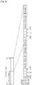
- FIG. 6illustrates ACK/NACK resources grouping method according to an embodiment of the present invention.
- three downlink subframes-to-one uplink subframe correspondenceis used in a radio frame configuration for HARQ operation.
- the three downlink subframesare indexed as i, (i+1) and (i+2) repectively and the one uplink subframe is indexed as j(j>i+2).
- the ACK/ NACK resourcesare divided into three ACK/NACK resource subsets where each subset carries ACK/NACK signals corresponding to one of the three downlink subframes exclusively.
- ACK/NACK resources in an uplink subframeare divided into L subsets when L downlink subframes are linked to that uplink subframe for an ACK/ NACK feedback. That means the number of ACK/NACK resource subsets in an uplink subframe is determined according to the number of downlink subframes linked with the uplink subframe.
- Each subsetcontains same or different amount of ACK/NACK resources. For convenience, let's assume each subset contains same number of ACK/NACK resources, M, so that the uplink subframe contains LxM ACK/NACK resources in total.
- the ACK/NACK resource subset 1, 2, ..., Linclude ACK/NACK resource 0 to M-1, M to 2M-1. and (L-1) ⁇ M to (L ⁇ M)-1 respectively.
- M ACK/NACK resources in each subsetare mapped to N CCEs in one of the L downlink subframes exclusively.
- CCEs in downlink subframe iare mapped to ACK/ NACK resource 0 to M-1
- CCEs in downlink subframe (i+1)are mapped to ACK/ NACK resource M to 2M-1
- CCEs in downlink subframe (i+2)are mapped to ACK/NACK resource 2M to 3M-1.
- the number of CCEs in each of the downlink subframescan be the same for each other or different from each other.
- Mcan be configured as a value equal to or smaller than N.
- N valueshould be maximum number of CCEs in a downlink subframe since actual number of CCEs can vary dynamically downlink subframe by subframe.
- ACK/NACK resourcesare divided into multiple subsets so that ACK/NACK resources of each subset are linked to one downlink subframe exclusively.
- N CCE (j)is the number of (Maximum) CCEs for jth CCE group.
- N CCE (j)should be replaced by N CCE if the number of (maximum) CCEs for all subframes is set equal.
- N gis the number of CCE groups in the PUCCH.
- N G CCEis equal to N g ⁇ N CCE if the number of (maximum) CCEs for all subframes is set equal.
- ACK/NACK resources in a subsetcan be remapped to different CCEs so that number of ACK/NACK resources in a subset can be smaller than number of CCEs in a downlink subframe.
- amount of reserved ACK/NACK resourcesis semi-statically configurable. This configurability and remapping approach can be applied to FDD mode as well.
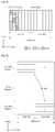
- FIG. 7illustrates CCE to ACK/NACK resource mapping method according to an embodiment of the present invention. It is assumed that M ACK/NACK resources in a subset are indexed from 0 to M-1 and N CCEs in a downlink subframe are indexed from 0 to N-1 where order of CCE index can be virtually interleaved within each PUCCH resource block (RB).
- RBPUCCH resource block
- CCEs 'a' through 'g'there are 7 CCEs (CCE index 'a' through 'g') for PDCCH and only 5 ACK/NACK resources (index 0 through 4) are used to transmit ACK/NACK signals corresponding to PDCCH. Because N>M, the same ACK/NACK resource is remapped to CCE. In other words, a plurality of CCEs are mapped to an ACK/NACK resource. CCEs 'b' and 'c' are mapped to ACK/NACK resource 0, CCEs 'd' and 'e' are mapped ACK/NACK resource 1. But, CCEs 'a', 'f', and 'g' are mapped exclusively to individual ACK/NACK resource 3, 2, 4 respectively.
- Repeated ACK/NACK index to CCE index mappingcauses restriction in PDCCH scheduling since a BS should consider a same ACK/NACK resource is not linked to multiple PDSCH transmissions in a downlink subframe. However, this is the cost for reducing the required amount uplink ACK/NACK resources.
- FIG. 8illustrates CCE to ACK/NACK resource mapping method according to another embodiment of the present invention. It is assumed that extended CP, 3 RBs for ACK/NACK signal, 12 ACK/NACK resources per RB and 18 CCEs per downlink subframe are used.
- CCEs in subframe xare indexed 0 through 17 and CCEs in subframe y are indexed 0 through 17.
- the USconverts the indices of the CCEs in the subframe y.
- the indices of the CCEs in the subframe yare converted into 18 through 35.
- the indices of the CCEs in the subframe xremains the same.
- all the CCEs over the subframe x and yare indexed 0 through 35. In such a manner, CCE indexes of multiple downlink subframes become consecutive. Then, the converted CCE indexes can be mapped to ACK/NACK indexes straightforwardly or in a per-RB interleaved way.
- ACK/NACK resources in a subsetWhen the number of ACK/NACK resources in a subset is smaller than the number of CCEs in a downlink subframe corresponding to the subset, some ACK/NACK resources needs to be remapped to ACK/NACK resources. In this case, ACK/NACK resources in the subset is remapped only to the CCEs in the corresponding downlink subframe. This remapping can be done by converting CCE indexes within a certain range which is mapped to an ACK/NACK resource subset in a downlink subframe. Therefore, different CCEs in a downlink subframe is assigned a same converted CCE indexes.
- FIG. 9illustrates CCE to ACK/NACK resource mapping method according to yet another embodiment of the present invention. It is assumed that extended CP, 3 RBs for ACK/NACK, 12 ACK/NACK resources per RB and 31 CCEs per downlink subframe are used.
- subframe x and yare mapped to a feedback subframe having ACK/NACK resources for the subframe x and y.
- the feedbakc subframeis used to transmit ACK/NACK signals corresponding to the subframe x and y.
- the ACK/NACK resources in the feedback subframeare divided into 2 subsets, because there are 2 subframes linked to the feedback subframe.
- Subset 1which has ACK/NACK resource indices 0 through 17, is mapped to the subframe x.
- subset 2which has ACK/NACK resource indices 18 through 35, is mapped to the subframe y.
- the number of CCEs in each subframeis larger than that of ACK/NACK resources in corresponding subset.
- Some ACK/NACK resources in subset 1are to be remapped to CCEs with indices 18 through 30 in the subframe x.
- some ACK/NACK resources in subset 2are to be remapped to CCEs with indices 0 through 12 in the subframe y.
- the indices of the extra CCEsare converted into other indices. These CCEs whose indices are converted for remapping are called extra CCEs, and the CCEs whose indices are not converted are called regular CCEs hereinafter.
- extra CCEsCCEs whose indices are converted for remapping
- regular CCEsregular CCEs hereinafter.
- the indices of the extra CCEs 18 through 30 in the subframe xare converted into 0 through 12, which already exists.
- the indices of the extra CCEs 0 through 17 in the subframe yare converted into 18 through 35.
- the converted indices of extra CCEs 0 through 12are duplicated with the indices of regular CCEs in the subframe x.
- the converted indices of extra CCEs 18 through 30are duplicated with the indices of regular CCEs in the subframe y.
- ACK/NACK resources with indices 0 through 12 in the subset 1are mapped to the extra CCEs with converted indices and to the regular CCEs with indices 0 through 12. That is, the remapping takes place. But ACK/NACK resources with indices 13 through 17 in the subset 1 are mapped only to the regular CCEs with indices 13 through 17.
- FIG. 10is a flow diagram illustrating ACK/NACK signal transmission according to an embodiment of the present invention.
- the downlink assignmentscan be referred to as downlink scheduling information or downlink grant.
- the downlink assignmentsare received in a first subframe, which contains downlink data.
- the downlink assignmentis transmitted based on a control channel element (CCE).
- the CCEis a logically indexed resource unit for control region of the first subframe.
- the downlink assignmentis transmitted on a downlink control channel which is PDCCH.
- the first subframecan be a downlink subframe or a plurality of downlink subframes in TDD system.
- the downlink shared channelis assigned according to the downlink assignments.
- the downlink shared channelis PDSCH.
- the ACK/NACK signalsindicate successful or unsuccessful reception of the downlink data.
- the ACK/NACK signals or a representative ACK/NACK signalby using uplink resources (which is mapped to the CCEs carrying the downlink assignment) by using uplink resources of a subset (S 130).
- the subsetis mapped to the first subframe, and at least one of the uplink resources is mapped to a plurality of CCEs in the first subframe.
- the second subframecan be an uplink subframe in TDD system.
- All functions described abovemay be performed by a processor such as a microprocessor, a controller, a microcontroller, and an application specific integrated circuit (ASIC) according to software or program code for performing the functions.
- the program codemay be designed, developed, and implemented on the basis of the descriptions of the present invention, and this is well known to those skilled in the art.
Landscapes
- Engineering & Computer Science (AREA)
- Signal Processing (AREA)
- Computer Networks & Wireless Communication (AREA)
- Mobile Radio Communication Systems (AREA)
- Detection And Prevention Of Errors In Transmission (AREA)
- Communication Control (AREA)
Description
- This invention relates to wireless communication, and more specifically, to a method of performing HARQ in wireless communication system.
- With the demand on a high-speed, large-volume data communication system for processing and transmitting a variety of information such as radio data as well as providing voice-oriented services, there is a need for developing a technique for transmitting large-volume data through the wireless communication network whose capacity is similar to that of the wired communication network. Therefore, an error handling method is essential for minimizing data loss and for increasing system transmission efficiency.
- Examples of the error handling method include a forward error correction (FEC) scheme and an automatic repeat request (ARQ) scheme. In the FEC scheme, a receiver corrects an error by appending an extra error correction code to information bits. In the ARQ scheme, when a received signal has an error, a transmitter corrects the error by retransmitting data. A hybrid ARQ (HARQ) scheme is a combination of the FEC scheme and the ARQ scheme. According to the HARQ scheme, performance is enhanced by confirming whether data received by the physical layer contains an error that cannot be decoded and requesting retransmission if there is an error.
- The HARQ operation is performed by at least one HARQ entity included in a user equipment (UE) or a base station (BS). The HARQ entity allows continuous data transmission while waiting for the feedback (i.e., the ACK signal or the NACK signal) on successful or unsuccessful reception of previous data transmission. In a downlink transmission, the UE receives resource assignment information from the BS, and the HARQ entity in the BS performs a HARQ process indicated by an HARQ information. To support the HARQ entity, the BS may operate a plurality of parallel HARQ processes.
- Hereinafter, a downlink denotes a communication link from the BS to the UE, and an uplink denotes a communication link from the UE to the BS. The downlink transmission and the HARQ operation are performed in the following manner. The BS transmits downlink assignement to the UE through a physical downlink control channel (PDCCH). Then, according to the downlink assignment, the UE receives downlink data from the BS through a physical downlink shared channel (PDSCH). When the UE receives the downlink data from the BS, the UE transmits an ACK/ NACK signal to the BS through a control channel (i.e., a physical uplink control channel (PUCCH)). If no error is detected in the received data, the ACK/NACK signal is an ACK signal. If an error is detected in the received data, the ACK/NACK signal is a NACK signal. When the BS receives NACK signal, the BS may retransmit the data to the UE. The downlink data here can be referred to as a codeword or a transport block.
- Resources such as frequency, time, code and space, should be distinguished between downlink transmission and uplink transmission, and there needs to a scheme by which downlink resources and uplink resources are not overlapped. The scheme is called duplexing. The duplexing is classified into frequency division duplexing (FDD), in which the uplink and downlink are identified according to frequencies, and time division duplexing (TDD) in which the uplink and downlink are identified according to times.
- In the FDD, frequencies having the same magnitude are symmetrically allocated in the uplink and downlink. The FDD has been widely used due to its structure suitable for symmetric services (e.g., voice calls). In recent years, however, researches on the TDD have actively been conducted due to its structure suitable for asymmetric services (e.g., Internet services). In the FDD, since the uplink and the downlink are identified in the frequency domain, seamless data transmission can be achieved between a base station (BS) and a user equipment (EU) in the time domain for each link.
- The TDD is suitable for the asymmetric services since time slots each having a different ratio can be allocated for the uplink and downlink. In addition, a channel condition is almost constant in the uplink and downlink since data is transmitted and received in the same frequency band in the uplink and downlink. Therefore, the channel condition can be immediately estimated when a signal is received. Accordingly, the TDD is suitable for an array antenna technique.
- In the TDD, an entire frequency band is used for uplink or downlink, and the uplink and downlink are identified in the time domain. Thus, the frequency band is used for the uplink for a certain period of time and is used for the downlink for the remaining periods of time, thereby disabling simultaneous data transmission/reception between the BS and the UE. If the uplink and downlink are alternately allocated with the same period of time, the BS does not have to inform whether a specific time point is used for uplink transmission or downlink transmission.
- The 3GPP Draft No. R1-080367, entitled "Uplink ACK/NACK timing for TDD", describes schemes for defining the uplink ACK/NACK timing for TDD operation in an LTE system.
- The 3GPP Draft No. R1-074206, entitled "Considerations on UL ACK/NACK operation", describes a mapping between CCE for DL data scheduling and UL ACK/NACK.
- In FDD as well as in TDD, uplink resources are more limited than downlink resources. Because there are not enough uplink resources for uplink feedback on downlink data reception. For example, 4 resource blocks are used for downlink transmission and 1 resource block for uplink transmission respectively. If a UE receives data from a BS using the 4 resource blocks, the UE only have 1 resource block to use to transmit an ACK/NACK signal for the data reception. This lack of uplink resource makes HARQ more difficult because the BS should decide whether to transmit a new data or retransmit the old data with relatively small amount of uplink feedback information comparing with the downlink data.
- A method of performing HARQ by effectively using limited uplink resource for uplink feedback is needed.
- It is an object of the present invention to provide a method of performing HARQ in wireless communication system. And the method of uplink ACK/NACK resource allocation related to the CCE index for downlink assignment in TDD mode as well as in FDD mode is also provided for the efficient utilization of uplink PUCCH resource and the commonality between FDD and TDD modes.
- According to an aspect of the present invention, a method of performing hybrid automatic repeat request (HARQ) performed by a user equipment (UE) in a wireless communication system is provided as set forth in the appended claims.
- Amount of reserved ACK/NACK resources is semi-statically configurable. Limited resources for uplink feedback are effectively used to support HARQ operation.
FIG. 1 shows a wireless communication system.FIG. 2 shows an exemplary structure of a radio frame.FIG. 3 shows another exemplary structure of a radio frame.FIG. 4 shows an exemplary structure of a downlink subframe.FIG. 5 shows an exemplary structure of an uplink subframe.FIG. 6 illustrates ACK/NACK resources grouping method according to an embodiment of the present invention.FIG. 7 illustrates CCE to ACK/NACK resource mapping method according to an embodiment of the present invention.FIG. 8 illustrates CCE to ACK/NACK resource mapping method according to another embodiment of the present invention.FIG. 9 illustrates CCE to ACK/NACK resource mapping method according to yet another embodiment of the present invention.FIG. 10 is a flow diagram illustrating ACK/NACK signal transmission according to an embodiment of the present invention.- The present invention will now be described more fully with reference to the accompanying drawings, in which exemplary embodiments of the invention are shown. The invention may, however, be embodied in many different forms and should not be construed as being limited to the embodiments set forth herein. Rather, these embodiments are provided so that this disclosure will be thorough and complete, and will fully convey the concept of the invention to those skilled in the art. In the drawings, the thicknesses of layers and regions are exaggerated for clarity. Like reference numerals in the drawings denote like elements.
FIG. 1 shows a wireless communication system. The wireless communication system can be widely deployed to provide a variety of communication services, such as voices, packet data, etc.- Referring to
FIG. 1 , the wireless communication system includes a base station (BS) 10 and at least one user equipment (UE) 20. TheBS 10 is generally a fixed station that communicates with theUE 20 and may be referred to as another terminology, such as a node-B, a base transceiver system (BTS), an access point, etc. There are one or more
cells within the coverage of theBS 10. TheUE 20 may be fixed or mobile, and may be referred to as another terminology, such as a mobile station (MS), a user terminal (UT), a subscriber station (SS), a wireless device, etc. - A downlink represents a communication link from the
BS 10 to theUE 20, and an uplink represents a communication link from theUE 20 to theBS 10. In downlink, a transmitter may be a part of theBS 10, and a receiver may be a part of theUE 20. In uplink, the transmitter may be a part of theUE 20, and the receiver may be a part of theBS 10. - Different multiple access schemes may be used for downlink and uplink transmissions. For example, orthogonal frequency division multiple access (OFDMA) is used for downlink, and single carrier-frequency division multiple access (SC-FDMA) is used for uplink.
- There is no limit in the multiple access scheme used in the wireless communication system. The multiple access scheme may be based on code division multiple access (CDMA), time division multiple access (TDMA), frequency division multiple access (FDMA), SC-FDMA, OFDMA, or other well-known modulation schemes. In these modulation schemes, signals received from multi-users are demodulated to increase capacity of the communication system.
- The layers of the radio interface protocol can be classified into a first layer (L1), a second layer (L2), and a third layer (L3) based on the open system interconnection (OSI) model that is well-known in a communication system. Compared with the OSI model, a physical (PHY) layer corresponds to the first layer L1, the medium access control (MAC) layer and the radio link control (RLC) layer correspond to the second layer L2, and the radio resource control (RRC) layer corresponds to the third layer L3. The physical layer provides an information transfer service using a physical channel, the MAC layer is connected with physical layer through transport channel, and the radio RRC layer serves to control radio resources between the UE and the network.
- Examples of a downlink transport channel include a broadcast channel (BCH) for transmitting system information and a downlink-shared channel (DL-SCH) for transmitting user traffic or control messages. The user traffic of downlink multicast or broadcast services or the control messages can be transmitted on the DL-SCH or an additional downlink multicast channel (DL-MCH). The downlink transport channel is mapped to a downlink physical channel. Examples of the downlink physical channel include a physical downlink shared channel (PDSCH) mapped to the DL-SCH, and a physical downlink control channel (PDCCH) for transmitting a control signal.
- Examples of an uplink transport channel include a random access channel (RACH) for transmitting initial control messages and an uplink-shared channel (UL-SCH) for transmitting user traffic or control messages. The uplink transport channel is mapped to an physical uplink channel. Examples of the physical uplink channel include a physical random access channel (PRACH) mapped to the RACH, a physical uplink shared channel (PUSCH) mapped to the UL-SCH, and a physical uplink control channel (PUCCH) for uplink control messages. The PUSCH is a physical uplink shared channel, and is used when the UE transmits data in uplink.
- The PDCCH is a downlink physical control channel and transmits control information for the PUSCH or the PDSCH. An uplink grant that is scheduling information for uplink data transmission and a downlink grant that is scheduling information for downlink data transmission can be transmitted through the PDCCH. Herein, the scheduling information implies control information including radio resource assignment for transmitting downlink data from the BS to the UE or for receiving uplink data from the UE, a modulation and coding scheme (MCS), MIMO information, etc.
FIG. 2 shows an exemplary structure of a radio frame.- Referring to
FIG. 2 , the radio frame includes 10 subframes. One subframe includes two slots. The subframe is a basic unit of data transmission. Downlink or uplink scheduling is performed in a subframe unit when the radio frame is used in a TDD system. One slot may include a plurality of OFDM symbols in a time domain and at least one subcarrier in a frequency domain. One slot may include 7 or 6 OFDM symbols. - The radio frame structure is shown for exemplary purposes only. Thus, the number of subframes included in the radio frame, the number of slots included in the subframe, and the number of OFDM symbols and subcarriers included in the slot can change variously.
FIG. 3 shows another exemplary structure of a radio frame.- Referring to
FIG. 3 , the radio frame includes two half-frames. Each half-frame has the same structure. Specifically, each half-frame includes 5 subframes and 3 fields, i.e., a downlink pilot time slot (DwPTS), a guard period (GP), and an uplink pilot time slot (UpPTS). The DwPTS is used for initial cell search, synchronization, or channel estimation in a UE. The UpPTS is used for channel estimation in a BS and uplink transmission synchronization of the UE. The GP is used to remove interference that occurs in uplink due to a multi-path delay of a downlink signal between uplink and downlink. FIG. 4 shows an exemplary structure of a downlink subframe.- Referring to
FIG. 4 , the first three OFDM symbols in the downlink subframe are allocated to control region which is used for PDCCH. The rest of the symbols in the downlink subframe are allocated to data region for PDSCH. In the control region, other control channels such as physical control format indicator channel (PCFICH), physical HARQ indicator channel (PHICH) are also allocated apart from PDCCH. The number of OFDM symbols in control region in a downlink subframe can be indicated by PCFICH. A UE reads control information on PDCCH and reads data on PDSCH by means of the control information. The number of OFDM symbols for PDCCH are given just as an exemplary purpose only. - The control region is composed of a plurality of control channel elements (CCEs), that is in a logical queue. Hereinafter CCEs is a logically indexed resource unit to carry a control channel (i.e. PDCCH). CCE corresponds to a group containing a plurality of physical resource elements. For example, CCE can corresponds to a group containing 9-physical resource element groups. The physical resource element group is used to define mapping control channel to a physical resource element.
- A plurality of PDCCHs can be transmitted in the control region. Each PDCCH carries control information, (i.e. downlink assignment). PDCCH is transmitted on a CCE basis or on consecutive CCEs aggregation basis. The format and the available bit numbers of PDCCH is determined based on the number of CCEs in the consecutive CCEs aggregation. Hereinafter, the number of CCEs used for PDCCH transmission is defined as CCE aggregation level. The CCE aggregation level is a unit based on which a UE monitors PDCCH. The size of the CCE aggregation level is defined by the number of contiguous CCEs. For instance, the CCE aggregation level can be one of a set {1, 2, 4, 8}.
- Table 1 below shows an example of PDCCH format, available number of bits for PDCCH according to the CCE aggregation level.
[Table] PDCCH format CCE aggregation level Number of resource element groups Number of PDCCH bits 0 1 9 72 1 2 18 144 2 4 36 288 3 8 72 576 - The CCE aggregation level can be different from UE to UE. For example, the CCE aggregation level (L) is 1 for
UE 2, UE andUE 6. The CCE aggregation level (L) is 2 forUE 3 andUE 5. The CCE aggregation level (L) is 4forUE land UE 7. - The control information on PDCCH is called downlink control information (DCI). DCI contains uplink scheduling information, downlink scheduling information, uplink power control command, paging control information, and indicator for RACH response, etc.
DCI format 0 is for PUSCH scheduling,DCI format 1 is for PDSCH codeword scheduling, DCI format 1A is for compact PDSCH codeword scheduling, DCI format 1C is for very simple scheduling of DL-SCH,DCI format 2 is for PDSCH scheduling in closed-loop spatial multiplexing mode, DCI format 2A is for PDSCH scheduling in open-loop spatial multiplexing mode, andDCI format 3 and 3A is for transmission power control for uplink channel. FIG. 5 shows an exemplary structure of an uplink subframe.- Referring to
FIG. 5 , uplink subframe is divided into a control region and a data region. The control region includes PUCCH and the data region includes PUSCH. One UE does not transmit PUCCH and PUSCH simultaneously to hold a single carier property when SC-FDMA is applied. - PUCCH is assignemd to one UE in a subframe as a RB pair. And RBs in the RB pair occupy different subcarriers in each of the slots. This is referred to as a frequency hopping of a RB pair in a slot boundary.
- PUCCH supports multiple formats. That is, uplink control information, which has different bit numbers per subframe according to modulation scheme, can be tranmitted on PUCCH.
- The following table represents PUCCH format, modulation scheme and bit numbers supported by 3GPP TS 36.211 V8.2.0.
[Table 2] PUCCH format Modulation scheme Number of bits per subframe,Mbit 1 N/A N/ A 1a BPSK 1 1b QPSK 2 2 QPSK 20 2a QPSK+BPSK 21 2b QPSK+QPSK 22 PUCCH format 1 is used to transmit scheduling request (SR), PUCCH format 1a/1b is used to transmit an ACK/NACK signal,PUCCH format 2 is used to transmit channel quality information (CQI), and PUCCH format 2a/2b is used to transmit CQI and an ACK/NACK signal.- In an arbitrary subframe, PUCCH format 1a/1b is used when an ACK/NACK signal is transmitted alone, whereas
PUCCH format 1 is used when SR is transmitted alone. If an ACK/NACK signal and SR are transmitted simultaneously, an SR resource assigned for positive SR transmission is used to transmit an ACK/NACK signal, and an ACK/ NACK resource assigned for ACK/NACK signal is used to transmit an ACK/NACK signal ans a negative SR. - Table 3 shows an example of downlink/uplink configurations of the radio frame in TDD system. The configuration of the radio frame indicates a specific rule according to which all subframes are allocated (or reserved) for uplink or downlink.
[Table ] Configuration Switch-point periodicity Subframe number 0 1 2 3 4 5 6 7 8 9 0 5 ms D S U U U D S U U U 1 5 ms D S U U D D S U U D 2 5 ms D S U D D D S U D D 3 10 ms D S U U U D D D D D 4 10 ms D S U U D D D D D D 5 10 ms D S U D D D D D D D 6 5 ms D S U U U D S U U D - In Table 3, 'D'denotes a subframe used for downlink transmission, and 'U' denotes a subframe used for uplink transmission. Further, 'S' denotes a special subframe that is used for a special purpose, such as, frame synchronization or downlink transmission. Hereinafter, a subframe used for downlink transmission is simply referred to as a downlink subframe, and a subframe used for uplink transmission is simply referred to as an uplink subframe. For each configuration, a position and the number of downlink and uplink subframes are different from each other within one radio frame.
- A time point at which downlink is switched to uplink, or vice versa, is defined as a switching point. A switch-point periodicity represents a period in which the same switching pattern is repeated between uplink and downlink. The switch-pint periodicity is 5ms or 10ms. For example, in case of the
configuration 1, switching occurs in the pattern of D->S->U->U->U from 0th to 4th subframes. In addition, from 5th to 9th subframes, switching occurs in the pattern of D->S->U->U->U in the same pattern as the previous switching. Since one subframe is 1ms, the switch-point periodicity is 5ms. That is, the switch-point periodicity is less than one radio frame length (i.e., 10ms), and switching is repeated one time within the radio frame. - For all configurations, 0th and 5th subframes and the DwPTS are used for downlink transmission. A 1st subframe in all configurations and a 6th subframe in
configurations - If the switch-point periodicity is 5ms, the UpPTS and 2nd and 7th subframes are reserved for uplink transmission. If the switch-point periodicity is 10ms, the UpPTS and the 2nd subframe are reserved for uplink transmission, and the DwPTS, and 7th and 9th subframes are reserved for downlink transmission.
- The configuration in table 3 may be system information known by both the BS and the UE. The BS can inform the UE that an uplink-downlink allocation state of the radio frame is modified by transmitting only a configuration index whenever the configuration of the radio frame changes. The configuration is a sort of downlink control information. Similarly to other scheduling information, the configuration may be transmitted on a physical downlink control channel (PDCCH). Alternatively, the configuration may be control information commonly transmitted on a broadcast channel to all UEs existing in a cell. In addition, the configuration may be included in the system information. The number of half-frames included in the radio frame, the number of subframe included in the half-frame, and the combination of the downlink subframe and the uplink subframe in the TDD system are shown for exemplary purposes only.
- When it comes to HARQ operation, a UE receives downlink data in a downlink subframe and transmits an ACK/NACK signal as a feedback in an uplink subframe. This causes a problem especially when there are more downlink subframes than uplink subframes in a radio frame. In table 3 above, let 'S' indicate a downlink subframe. In case of
configuration 2, a radio frame includes 8 downlink subframes and 2 uplink subframes. That is, the radio of downlink subframe to uplink subframe is 4:1. In this case, a UE receives data throughout 4 downlink subframes and feeds back ACK/ NACK signals in a single uplink subframe for HARQ operation. When the number of downlink subframes are larger than that of uplink subframes, radio resources used to transmit ACK/NACK signals are insufficient. - So the linkage of downlink subframe and uplink subframe for uplink ACK/NACK feedback needs to be defined for each downlink/uplink configuration in table 3, where one uplink subframe may carry ACK/NACK signals for multiple downlink subframes depending on the downlink/uplink configuration. A predefined relationship among downlink subframe(s) and uplink subframe(s) in order to avoid an excessive uplink ACK/NACK resource reservation is described hereinafter. The amount of reserved ACK/NACK resources should be semi-statically configurable so that the number of ACK/NACK resources can be set less than the number of CCEs in a corresponding downlink subframe.
- Semi-static DL/UL linkage in the configurations in table 3 according to the present invention is described in table 4 below.

- In table 4, special downlink subframes (indicated by 'S' in table 3) are used for downlink subframe, and indicated by 'D' to avoid confusions. An ACK/NACK signal corresponding to downlink subframe D#n is transmitted in uplink subframe U#n. For example, a downlink subframe D1 in radio frame i corresponds to an uplink subframe U1 in radio frame (i+1). Even though there are some subframes with no #n attached (D and U), those subframes are also linked to other subframes for ACK/NACK signal feedback.
- In most configurations, all or some uplink subframes are linked to multiple downlink subframes. In other word, one uplink subframe is associated with at least one donwlink subframe. In
configuration 0, there are 4 one downlink subframe-to-one uplink subframe correspondence, and 2 uplink subframes are not linked to any downlink subframe. Inconfiguration 1, there are 2 two downlink subframes-to-one uplink subframe correspondence, and 2 one downlink subframe-to-one uplink subframe correspondence. Inconfiguration 2, there are 2 four downlink subframe-to-one uplink subframe correspondence. Inconfiguration 3, there are 2 two downlink subframe-to-one uplink subframe correspondence, and 1 three downlink subframes-to-one uplink subframe correspondence. In other configurations, it is easily assumed the correspodence relationship between downlink subframe and uplink subframe. - Hereinafter, uplink radio resource which is used to transmit an ACK/NACK signal is called an ACK/NACK resource. The ACK/NACK resource can be combinations of resource block, cyclic shift and orthogonal cover. The ACK/NACK resource is assigned according to an uplink scheduling information, such as uplink grant. A subset which includes at least one ACK/NACK resource is called an ACK/NACK resource subset. An uplink subframe can contain a plurality of ACK/NACK resource subsets. The number of ACK/NACK resources in each of the ACK/NACK resource subsets can be varioius.
- In
configuration - The correspondence between downlink subframe(s) and uplink subframe(s) for an ACK/NACK signal feedback in each configuration of a radio frame is described above. From now on, the method of making ACK/NACK resource subsets in an uplink subframe is described. The method is about grouping or dividing ACK/NACK resources efficiently in a situation where there are not enough ACK/NACK resources to deal with all downlink data in HARQ operation. The method is applied to a FDD system as well as a TDD system.
FIG. 6 illustrates ACK/NACK resources grouping method according to an embodiment of the present invention.- Referring to
FIG. 6 , three downlink subframes-to-one uplink subframe correspondence is used in a radio frame configuration for HARQ operation. The three downlink subframes are indexed as i, (i+1) and (i+2) repectively and the one uplink subframe is indexed as j(j>i+2). This means that the jth uplink subframe should carry ACK/NACK signals corresponding to the three downlink subframes. So the ACK/ NACK resources are divided into three ACK/NACK resource subsets where each subset carries ACK/NACK signals corresponding to one of the three downlink subframes exclusively. - To generalize this, ACK/NACK resources in an uplink subframe are divided into L subsets when L downlink subframes are linked to that uplink subframe for an ACK/ NACK feedback. That means the number of ACK/NACK resource subsets in an uplink subframe is determined according to the number of downlink subframes linked with the uplink subframe.
- Each subset contains same or different amount of ACK/NACK resources. For convenience, let's assume each subset contains same number of ACK/NACK resources, M, so that the uplink subframe contains LxM ACK/NACK resources in total. The ACK/
NACK resource subset NACK resource 0 to M-1, M to 2M-1. and (L-1)×M to (L×M)-1 respectively. - Then, M ACK/NACK resources in each subset are mapped to N CCEs in one of the L downlink subframes exclusively. CCEs in downlink subframe i are mapped to ACK/
NACK resource 0 to M-1, CCEs in downlink subframe (i+1) are mapped to ACK/ NACK resource M to 2M-1, and CCEs in downlink subframe (i+2) are mapped to ACK/NACK resource 2M to 3M-1. The number of CCEs in each of the downlink subframes can be the same for each other or different from each other. M can be configured as a value equal to or smaller than N. Here, N value should be maximum number of CCEs in a downlink subframe since actual number of CCEs can vary dynamically downlink subframe by subframe. - In summary, when an uplink subframe carries ACK/NACK signals for multiple downlink subframes, ACK/NACK resources are divided into multiple subsets so that ACK/NACK resources of each subset are linked to one downlink subframe exclusively.
- The method of dividing ACK/NACK resource into a plurality of subsets is given by a math figure below.
MathFigure 1
- Where a CCE group consists of CCEs in a single subframe and NCCE(j) is the number of (Maximum) CCEs for jth CCE group. NCCE(j) should be replaced by NCCE if the number of (maximum) CCEs for all subframes is set equal. Ng is the number of CCE groups in the PUCCH. NGCCE is equal to Ng×NCCE if the number of (maximum) CCEs for all subframes is set equal.
- Hereinafter, a method of mapping between ACK/NACK resource and CCE is described. ACK/NACK resources in a subset can be remapped to different CCEs so that number of ACK/NACK resources in a subset can be smaller than number of CCEs in a downlink subframe. As a result, amount of reserved ACK/NACK resources is semi-statically configurable. This configurability and remapping approach can be applied to FDD mode as well.
FIG. 7 illustrates CCE to ACK/NACK resource mapping method according to an embodiment of the present invention. It is assumed that M ACK/NACK resources in a subset are indexed from 0 to M-1 and N CCEs in a downlink subframe are indexed from 0 to N-1 where order of CCE index can be virtually interleaved within each PUCCH resource block (RB).- Referring to
FIG. 7 , there are 7 CCEs (CCE index 'a' through 'g') for PDCCH and only 5 ACK/NACK resources (index 0 through 4) are used to transmit ACK/NACK signals corresponding to PDCCH. Because N>M, the same ACK/NACK resource is remapped to CCE. In other words, a plurality of CCEs are mapped to an ACK/NACK resource. CCEs 'b' and 'c' are mapped to ACK/NACK resource 0, CCEs 'd' and 'e' are mapped ACK/NACK resource 1. But, CCEs 'a', 'f', and 'g' are mapped exclusively to individual ACK/NACK resource - Repeated ACK/NACK index to CCE index mapping causes restriction in PDCCH scheduling since a BS should consider a same ACK/NACK resource is not linked to multiple PDSCH transmissions in a downlink subframe. However, this is the cost for reducing the required amount uplink ACK/NACK resources. In general, this ACK/ NACK index to multiple CCE index mapping can be allowed when L=1 as well. That is, when an uplink subframe corresponds to a single downlink subframe. Because there seems to be no reason to forbid the same mapping scheme to be applied. Furthermore, this mapping scheme can be also applied to FDD mode for efficient PUCCH resource utilization and commonality between FDD and TDD.
FIG. 8 illustrates CCE to ACK/NACK resource mapping method according to another embodiment of the present invention. It is assumed that extended CP, 3 RBs for ACK/NACK signal, 12 ACK/NACK resources per RB and 18 CCEs per downlink subframe are used.- Referring to
FIG.8 , CCEs in subframe x are indexed 0 through 17 and CCEs in subframe y are indexed 0 through 17. When a UE receives CCEs in the subframe x and y, the US converts the indices of the CCEs in the subframe y. As a result, the indices of the CCEs in the subframe y are converted into 18 through 35. The indices of the CCEs in the subframe x remains the same. And all the CCEs over the subframe x and y are indexed 0 through 35. In such a manner, CCE indexes of multiple downlink subframes become consecutive. Then, the converted CCE indexes can be mapped to ACK/NACK indexes straightforwardly or in a per-RB interleaved way. - When the number of ACK/NACK resources in a subset is smaller than the number of CCEs in a downlink subframe corresponding to the subset, some ACK/NACK resources needs to be remapped to ACK/NACK resources. In this case, ACK/NACK resources in the subset is remapped only to the CCEs in the corresponding downlink subframe. This remapping can be done by converting CCE indexes within a certain range which is mapped to an ACK/NACK resource subset in a downlink subframe. Therefore, different CCEs in a downlink subframe is assigned a same converted CCE indexes.
FIG. 9 illustrates CCE to ACK/NACK resource mapping method according to yet another embodiment of the present invention. It is assumed that extended CP, 3 RBs for ACK/NACK, 12 ACK/NACK resources per RB and 31 CCEs per downlink subframe are used.- Referring to
FIG. 9 , subframe x and y are mapped to a feedback subframe having ACK/NACK resources for the subframe x and y. The feedbakc subframe is used to transmit ACK/NACK signals corresponding to the subframe x and y. The ACK/NACK resources in the feedback subframe are divided into 2 subsets, because there are 2 subframes linked to the feedback subframe. Subset 1, which has ACK/NACK resource indices 0 through 17, is mapped to the subframe x. Andsubset 2, which has ACK/NACK resource indices 18 through 35, is mapped to the subframe y.- The number of CCEs in each subframe is larger than that of ACK/NACK resources in corresponding subset. Some ACK/NACK resources in
subset 1 are to be remapped to CCEs withindices 18 through 30 in the subframe x. And some ACK/NACK resources insubset 2 are to be remapped to CCEs withindices 0 through 12 in the subframe y. - Before remapping of ACK/NACK resources and CCEs, the indices of the extra CCEs are converted into other indices. These CCEs whose indices are converted for remapping are called extra CCEs, and the CCEs whose indices are not converted are called regular CCEs hereinafter. For example, the indices of the
extra CCEs 18 through 30 in the subframe x are converted into 0 through 12, which already exists. And the indices of theextra CCEs 0 through 17 in the subframe y are converted into 18 through 35. - Then, the converted indices of
extra CCEs 0 through 12 are duplicated with the indices of regular CCEs in the subframe x. And the the converted indices ofextra CCEs 18 through 30 are duplicated with the indices of regular CCEs in the subframe y. - ACK/NACK resources with
indices 0 through 12 in thesubset 1 are mapped to the extra CCEs with converted indices and to the regular CCEs withindices 0 through 12. That is, the remapping takes place. But ACK/NACK resources with indices 13 through 17 in thesubset 1 are mapped only to the regular CCEs with indices 13 through 17. - The same remapping procedure is applied to the subframe y and the
subset 2. FIG. 10 is a flow diagram illustrating ACK/NACK signal transmission according to an embodiment of the present invention.- Referring to
FIG. 10 , receiving downlink assignments (S100). The downlink assignments can be referred to as downlink scheduling information or downlink grant. The downlink assignments are received in a first subframe, which contains downlink data. The downlink assignment is transmitted based on a control channel element (CCE). The CCE is a logically indexed resource unit for control region of the first subframe. The downlink assignment is transmitted on a downlink control channel which is PDCCH. The first subframe can be a downlink subframe or a plurality of downlink subframes in TDD system. - Receiving downlink data on a downlink shared channel in the first subframe (S110). The downlink shared channel is assigned according to the downlink assignments. The downlink shared channel is PDSCH.
- Generating ACK/NACK signals (S 120). The ACK/NACK signals indicate successful or unsuccessful reception of the downlink data.
- Transmitting in a second sub frame, the ACK/NACK signals or a representative ACK/NACK signal by using uplink resources (which is mapped to the CCEs carrying the downlink assignment) by using uplink resources of a subset (S 130). The subset is mapped to the first subframe, and at least one of the uplink resources is mapped to a plurality of CCEs in the first subframe. The second subframe can be an uplink subframe in TDD system.
- All functions described above may be performed by a processor such as a microprocessor, a controller, a microcontroller, and an application specific integrated circuit (ASIC) according to software or program code for performing the functions. The program code may be designed, developed, and implemented on the basis of the descriptions of the present invention, and this is well known to those skilled in the art.
- While the present invention has been particularly shown and described with reference to exemplary embodiments thereof, it will be understood by those skilled in the art that various changes in form and details may be made therein without departing from the scope of the invention as defined by the appended claims. The exemplary embodiments should be considered in descriptive sense only and not for purposes of limitation. Therefore, the scope of the invention is defined not by the detailed description of the invention but by the appended claims.


Claims (4)
- A method of performing hybrid automatic repeat request, HARQ, performed by a user equipment, UE, in a wireless communication system, the method comprising:receiving downlink assignments in a plurality of downlink subframes, which are time division duplexing, TDD, subframes, each of the downlink assignments being transmitted based on a control channel element, CCE;receiving downlink data on a downlink shared channel in the plurality of downlink subframes, each being indexed by downlink subframes indexes, the downlink shared channel being assigned according to the downlink assignments, the plurality of downlink subframes being linked with a single uplink subframe, which is a TDD subframe; anddetermining ACK/NACK uplink resources for ACK/NACK signal of the downlink data, wherein the ACK/NACK uplink resources are of the single uplink subframe, wherein the ACK/NACK uplink resources are divided into ACK/NACK resource subsets, wherein a number of the ACK/NACK resource subsets is determined by a number of the plurality of downlink subframes being linked with the single uplink subframe, wherein an individual ACK/NACK uplink resource in each ACK/NACK resource subset is determined by a CCE index of a corresponding CCE used for transmission of a corresponding downlink assignment in the plurality of downlink subframes.
- The method of claim 1, wherein the ACK/NACK signal is transmitted on an uplink control channel.
- The method of claim 2, wherein the uplink control channel is a physical uplink control channel, PUCCH.
- The method of clam 1, wherein the downlink shared channel is a physical downlink shared channel, PDSCH.
Applications Claiming Priority (3)
| Application Number | Priority Date | Filing Date | Title |
|---|---|---|---|
| US3698708P | 2008-03-16 | 2008-03-16 | |
| US4013208P | 2008-03-27 | 2008-03-27 | |
| PCT/KR2009/001270WO2009116754A2 (en) | 2008-03-16 | 2009-03-13 | Method of performing hybrid automatic repeat request (harq) in wireless communication system |
Publications (3)
| Publication Number | Publication Date |
|---|---|
| EP2248294A2 EP2248294A2 (en) | 2010-11-10 |
| EP2248294A4 EP2248294A4 (en) | 2014-03-05 |
| EP2248294B1true EP2248294B1 (en) | 2018-05-02 |
Family
ID=41091367
Family Applications (1)
| Application Number | Title | Priority Date | Filing Date |
|---|---|---|---|
| EP09721591.7AActiveEP2248294B1 (en) | 2008-03-16 | 2009-03-13 | Method of performing hybrid automatic repeat request (harq) in wireless communication system |
Country Status (5)
| Country | Link |
|---|---|
| US (2) | US7957329B2 (en) |
| EP (1) | EP2248294B1 (en) |
| JP (1) | JP5721443B2 (en) |
| CN (2) | CN102017506B (en) |
| WO (1) | WO2009116754A2 (en) |
Families Citing this family (93)
| Publication number | Priority date | Publication date | Assignee | Title |
|---|---|---|---|---|
| CN102017506B (en) | 2008-03-16 | 2014-06-04 | Lg电子株式会社 | Method of performing hybrid automatic repeat request (HARQ) in wireless communication system |
| US8218661B2 (en)* | 2008-03-18 | 2012-07-10 | Mitsubishi Electric Research Laboratories, Inc. | OFDMA based medium access control and frame structure design for industrial applications |
| US8942080B2 (en)* | 2008-04-17 | 2015-01-27 | Texas Instruments Incorporated | Transmission of bundled ACK/NAK bits |
| CN102291767B (en)* | 2008-04-29 | 2013-12-04 | 华为技术有限公司 | Method, device and system for distributing responding channels for users |
| US9288021B2 (en) | 2008-05-02 | 2016-03-15 | Qualcomm Incorporated | Method and apparatus for uplink ACK/NACK resource allocation |
| KR101589600B1 (en)* | 2008-08-05 | 2016-01-28 | 삼성전자주식회사 | Method and apparatus for transmitting and receiving an uplink response channel for a downlink data channel in a mobile communication system using an orthogonal frequency division multiple access |
| KR20100019947A (en) | 2008-08-11 | 2010-02-19 | 엘지전자 주식회사 | Method of transmitting information in wireless communication system |
| KR101571566B1 (en)* | 2008-08-11 | 2015-11-25 | 엘지전자 주식회사 | Method for transmitting a control signal in a wireless communication system |
| KR101603338B1 (en) | 2008-08-11 | 2016-03-15 | 엘지전자 주식회사 | Method and apparatus of transmitting information in wireless communication system |
| KR101646249B1 (en)* | 2008-08-11 | 2016-08-16 | 엘지전자 주식회사 | Method and apparatus of transmitting information in wireless communication system |
| KR101597573B1 (en)* | 2008-08-11 | 2016-02-25 | 엘지전자 주식회사 | Uplink transmission method of control information |
| KR101487562B1 (en)* | 2008-11-11 | 2015-01-30 | 엘지전자 주식회사 | Data Relay Method in TDD-based Wireless Communication System |
| KR101243508B1 (en)* | 2008-11-14 | 2013-03-20 | 엘지전자 주식회사 | Method and apparatus for signal transmission in wireless communication system |
| EP3113382B1 (en) | 2008-11-14 | 2017-08-30 | Lg Electronics Inc. | Method and apparatus for information transmission in wireless communication system |
| US8228862B2 (en)* | 2008-12-03 | 2012-07-24 | Samsung Electronics Co., Ltd. | Method and system for reference signal pattern design |
| KR101104965B1 (en)* | 2008-12-19 | 2012-01-12 | 한국전자통신연구원 | Scheduling Method and Device in Base Station Considering Downlink Control Channel Resource |
| JP5199223B2 (en)* | 2008-12-30 | 2013-05-15 | 創新音▲速▼股▲ふん▼有限公司 | Method and communication apparatus for improving ACK / NACK bundling |
| CN101771515A (en)* | 2008-12-30 | 2010-07-07 | 三星电子株式会社 | Method for transmitting hybrid automatic repeat request-acknowledgement character (HARQ-ACK) |
| KR101641119B1 (en)* | 2009-02-02 | 2016-07-20 | 삼성전자 주식회사 | Method of receaving and transmssion control channel in a wireless comunication system and an apparatus thereof |
| US9450727B2 (en)* | 2009-02-03 | 2016-09-20 | Google Technology Holdings LLC | Physical layer acknowledgement signaling resource allocation in wireless communication systems |
| US8767632B2 (en)* | 2009-02-05 | 2014-07-01 | Motorola Mobility Llc | Method for uplink acknowledgement/non-acknowledgement messages in a wireless communication system |
| KR20100091876A (en) | 2009-02-11 | 2010-08-19 | 엘지전자 주식회사 | Ue behavior for multi-antenna transmission |
| US9001745B2 (en)* | 2009-03-13 | 2015-04-07 | Blackberry Limited | HARQ process number management for downlink carrier |
| KR101761824B1 (en) | 2009-03-16 | 2017-07-26 | 블랙베리 리미티드 | Harq process number management for downlink carrier aggregation |
| US9401779B2 (en) | 2009-03-29 | 2016-07-26 | Lg Electronics Inc. | Method for transmitting control information in wireless communication system and apparatus therefor |
| WO2010124238A2 (en) | 2009-04-24 | 2010-10-28 | Interdigital Patent Holdings, Inc. | Method and apparatus for sending hybrid automatic repeat request feedback for component carrier aggregation |
| WO2010123304A2 (en) | 2009-04-24 | 2010-10-28 | Samsung Electronics Co., Ltd. | Multiplexing large payloads of control information from user equipments |
| US8649281B2 (en)* | 2009-04-27 | 2014-02-11 | Samsung Electronics Co., Ltd. | Control design for backhaul relay to support multiple HARQ processes |
| US8379547B2 (en)* | 2009-05-15 | 2013-02-19 | Telefonaktiebolaget L M Ericsson (Publ) | Resource selection for transmission of multiple ACK/NACK on PUCCH channel |
| US20120069826A1 (en)* | 2009-06-09 | 2012-03-22 | Panasonic Corporation | Terminal device and signal multiplexing control method |
| CN102045140B (en)* | 2009-10-10 | 2013-06-12 | 中兴通讯股份有限公司 | Method and terminal for feeding back ACK/NACK (Acknowledgement/Non-acknowledgement) information with uplink sub-frame |
| AU2014202317B2 (en)* | 2009-10-19 | 2016-01-21 | Samsung Electronics Co., Ltd. | Transmission diversity and multiplexing for HARQ-ACK signals in communication systems |
| RU2568322C2 (en) | 2009-10-19 | 2015-11-20 | Самсунг Электроникс Ко., Лтд. | Transmission diversity and multiplexing for harq-ack signals in communication systems |
| KR101385435B1 (en)* | 2009-10-20 | 2014-04-14 | 엘지전자 주식회사 | Method and apparatus for transmitting acknowledgement in wireless communication system |
| US9264184B2 (en) | 2009-10-30 | 2016-02-16 | Sony Corporation | Coordinated signaling of scheduling information for uplink and downlink communications |
| KR101821407B1 (en)* | 2009-12-16 | 2018-01-24 | 엘지전자 주식회사 | Apparatus and method of transmitting reception acknowledgement in wireless communication system |
| US8873454B2 (en) | 2009-12-18 | 2014-10-28 | Qualcomm Incorporated | Apparatus and method for transmit-response timing for relay operation in wireless communications |
| RU2543562C2 (en)* | 2010-02-02 | 2015-03-10 | Чайна Мобайл Коммуникейшенс Корпорейшн | Method and apparatus for distributing downlink subframes |
| EP2536202B1 (en)* | 2010-02-09 | 2017-07-05 | Sharp Kabushiki Kaisha | Communication method, mobile station apparatus, base station apparatus and mobile communication system |
| GB201002215D0 (en) | 2010-02-10 | 2010-03-31 | Nec Corp | Resource allocation signalling |
| CN102083211B (en)* | 2010-03-29 | 2017-04-19 | 电信科学技术研究院 | Determining method and equipment of uplink control channel resources |
| CN101808409B (en)* | 2010-04-01 | 2015-03-25 | 中兴通讯股份有限公司 | Method and system for configuration of measurement reference signals in LTE-A system |
| US9654265B2 (en)* | 2010-04-08 | 2017-05-16 | Qualcomm Incorporated | Systems, apparatus and methods to facilitate transmission of acknowledgement signals in wireless communication systems |
| US8670496B2 (en) | 2010-04-14 | 2014-03-11 | Samsung Electronics Co., Ltd. | Method and system for mapping uplink control information |
| US8576791B2 (en) | 2010-04-27 | 2013-11-05 | Qualcomm Incorporated | Sharing control channel resources |
| CN102237991B (en)* | 2010-04-30 | 2016-08-24 | 北京三星通信技术研究有限公司 | The method sending ACK/NACK information in a tdd system |
| US8879513B2 (en) | 2010-05-12 | 2014-11-04 | Samsung Electronics Co., Ltd. | Uplink transmission apparatus and method for mobile communication system supporting uplink MIMO |
| US8934421B2 (en) | 2010-05-12 | 2015-01-13 | Qualcomm Incorporated | Acknowledgment transmissions under cross-subframe resource allocation in LTE-A |
| BR112012020398B8 (en)* | 2010-10-04 | 2021-04-20 | Ericsson Telefon Ab L M | method for the control of retransmission on user equipment, and disposition on user equipment |
| WO2012060629A2 (en) | 2010-11-02 | 2012-05-10 | 엘지전자 주식회사 | Method and device for transmitting/receiving uplink control information in wireless communication system |
| US9603169B2 (en)* | 2010-11-05 | 2017-03-21 | Pantech Inc., Ltd. | Method and device for transmitting and receiving aperiodic reference signal |
| US10873425B2 (en) | 2010-11-12 | 2020-12-22 | Qualcomm Incorporated | Acknowledgement / negative acknowledgement feedback for TDD |
| CN102611540A (en)* | 2011-01-20 | 2012-07-25 | 北京三星通信技术研究有限公司 | Method for feeding back ACK/NACK (acknowledgement character/negative acknowledgement) information |
| KR101849107B1 (en) | 2011-02-17 | 2018-04-16 | 삼성전자주식회사 | Method and apparatus of allocating uplink feedback channel for feeding back ack/nack of data packets corresponding to e-pdcch |
| US9155079B2 (en) | 2011-03-25 | 2015-10-06 | Lg Electronics Inc. | Communication method and device in a wireless communication system |
| CN107147480B (en) | 2011-04-22 | 2021-02-02 | 北京三星通信技术研究有限公司 | Method and device for supporting synchronous HARQ transmission of PUSCH |
| CN102223219B (en)* | 2011-06-16 | 2017-07-18 | 中兴通讯股份有限公司 | HARQ ACK feedback method for treating and system |
| CN102868502B (en)* | 2011-07-05 | 2017-08-25 | 中兴通讯股份有限公司 | A kind of method and device for adjusting physical downlink control channel polymerization |
| US8705556B2 (en)* | 2011-08-15 | 2014-04-22 | Blackberry Limited | Notifying a UL/DL configuration in LTE TDD systems |
| US8923274B2 (en) | 2011-08-15 | 2014-12-30 | Blackberry Limited | Notifying a UL/DL configuration in LTE TDD systems |
| KR101962245B1 (en) | 2011-09-23 | 2019-03-27 | 삼성전자 주식회사 | Method and apparatus for accessing of narrowband terminal to a wireless communication system supporting both wideband terminal and narrowband terminal |
| KR20130032798A (en)* | 2011-09-23 | 2013-04-02 | 주식회사 팬택 | Method and apparatus for dynamically transmitting control information in wireless communication system |
| US20130083746A1 (en)* | 2011-09-30 | 2013-04-04 | Interdigital Patent Holdings, Inc. | Method and apparatus for allocating resources for an enhanced physical hybrid automatic repeat request indicator channel |
| KR101973466B1 (en)* | 2011-11-01 | 2019-04-30 | 엘지전자 주식회사 | Method for transmitting and receiving a signal, and apparatus therefor |
| CN103209483B (en)* | 2012-01-12 | 2015-09-09 | 华为技术有限公司 | Method for transmitting uplink control information, user equipment and base station |
| US9769857B2 (en) | 2012-02-27 | 2017-09-19 | Futurewei Technologies, Inc. | System and method for allocating network resources |
| US8848591B2 (en) | 2012-02-27 | 2014-09-30 | Futurewei Technologies, Inc. | System and method for message acknowledgment feedback for device-to-device communication overlaid on a cellular network |
| US9209945B2 (en) | 2012-02-27 | 2015-12-08 | Futurewei Technologies, Inc. | System and method for hybrid automatic repeat request timing for device-to-device communication overlaid on a cellular network |
| US9526091B2 (en) | 2012-03-16 | 2016-12-20 | Intel Corporation | Method and apparatus for coordination of self-optimization functions in a wireless network |
| WO2014048472A1 (en) | 2012-09-27 | 2014-04-03 | Huawei Technologies Co., Ltd. | Methods and nodes in a wireless communication system |
| CN104904154B (en) | 2013-01-03 | 2018-06-19 | Lg电子株式会社 | For sending the method and apparatus of uplink signal in a wireless communication system |
| US9647818B2 (en) | 2013-01-03 | 2017-05-09 | Intel IP Corporation | Apparatus and method for single-tone device discovery in wireless communication networks |
| KR102197967B1 (en) | 2013-01-09 | 2021-01-04 | 엘지전자 주식회사 | Method and apparatus for transmitting receipt confirmation reply in wireless communication system |
| US9794876B2 (en) | 2013-03-29 | 2017-10-17 | Intel IP Corporation | Extended paging discontinuous reception (DRX) cycles in wireless communication networks |
| US9445338B2 (en)* | 2013-04-04 | 2016-09-13 | Intel IP Corporation | Reconfiguration control channel resource mapping collision avoidance |
| US9160515B2 (en) | 2013-04-04 | 2015-10-13 | Intel IP Corporation | User equipment and methods for handover enhancement using scaled time-to-trigger and time-of-stay |
| US9191178B2 (en) | 2013-04-04 | 2015-11-17 | Intel IP Corporation | Enhanced node B and method for RRC connection establishment for small data transfers |
| KR101784760B1 (en) | 2013-04-04 | 2017-11-06 | 인텔 아이피 코포레이션 | Reconfiguration control channel resource mapping collision avoidance |
| US10334569B2 (en) | 2013-06-05 | 2019-06-25 | Texas Instruments Incorporated | NLOS wireless backhaul downlink communication |
| US9313698B2 (en) | 2013-10-11 | 2016-04-12 | Blackberry Limited | Method and apparatus for handover in heterogeneous cellular networks |
| US11743897B2 (en)* | 2013-12-20 | 2023-08-29 | Qualcomm Incorporated | Techniques for configuring uplink channels in unlicensed radio frequency spectrum bands |
| US9668288B2 (en)* | 2014-03-19 | 2017-05-30 | Acer Incorporated | Method of handling device-to-device operation and related communication device |
| US10075970B2 (en) | 2015-03-15 | 2018-09-11 | Qualcomm Incorporated | Mission critical data support in self-contained time division duplex (TDD) subframe structure |
| US10342012B2 (en) | 2015-03-15 | 2019-07-02 | Qualcomm Incorporated | Self-contained time division duplex (TDD) subframe structure |
| US9936519B2 (en) | 2015-03-15 | 2018-04-03 | Qualcomm Incorporated | Self-contained time division duplex (TDD) subframe structure for wireless communications |
| EP3264651B1 (en) | 2015-04-01 | 2020-05-06 | Huawei Technologies Co., Ltd. | Polar code hybrid automatic retransmission request method and device |
| MX367996B (en)* | 2015-04-10 | 2019-09-13 | Ericsson Telefon Ab L M | Method and user equipment for compacting harq feedback. |
| WO2016190620A1 (en)* | 2015-05-22 | 2016-12-01 | 엘지전자 주식회사 | Wireless device and method for receiving downlink control channel |
| US9992790B2 (en)* | 2015-07-20 | 2018-06-05 | Qualcomm Incorporated | Time division duplex (TDD) subframe structure supporting single and multiple interlace modes |
| EP3607684B1 (en)* | 2017-04-03 | 2021-06-02 | Telefonaktiebolaget LM Ericsson (publ) | Harq handling for nodes with variable processing times |
| WO2019148456A1 (en) | 2018-02-02 | 2019-08-08 | 北京小米移动软件有限公司 | Information transmission method, device, and system, and storage medium |
| US12207235B2 (en) | 2019-10-29 | 2025-01-21 | Lg Electronics Inc. | Logical channel prioritization based on HARQ feedback |
| US11877299B2 (en)* | 2020-03-05 | 2024-01-16 | Qualcomm Incorporated | Control channel resources for group-feedback in multi-cast |
Family Cites Families (27)
| Publication number | Priority date | Publication date | Assignee | Title |
|---|---|---|---|---|
| KR100557168B1 (en) | 2003-06-13 | 2006-03-03 | 삼성전자주식회사 | Fast Forward Packet Data Demodulation Method in Communication System Using Fast Forward Packet Access |
| CN100355231C (en)* | 2003-12-19 | 2007-12-12 | 上海贝尔阿尔卡特股份有限公司 | Data transmission method having HARQ in multi-carrier system |
| EP1545040B1 (en)* | 2003-12-19 | 2009-04-22 | Panasonic Corporation | HARQ protocol with synchronous retransmissions |
| CN1635729A (en)* | 2003-12-26 | 2005-07-06 | 北京三星通信技术研究有限公司 | Method for Transmitting Response Signal Using Common Channel |
| KR20050081566A (en)* | 2004-02-14 | 2005-08-19 | 삼성전자주식회사 | Method for harq transmission of compressed mode in communication system using high speed downlink packet access scheme |
| KR100640516B1 (en) | 2004-02-27 | 2006-10-30 | 삼성전자주식회사 | Method and device for transmitting channel quality information in orthogonal frequency division multiplexing communication system |
| US7228079B2 (en)* | 2004-08-03 | 2007-06-05 | Hewlett-Packard Development Company, L.P. | Method and apparatus for detecting a media jam |
| US20060062173A1 (en)* | 2004-09-17 | 2006-03-23 | Lucent Technologies, Inc. | Hybrid automatic repeat request operation during soft hand offs in a wireless system |
| KR100684319B1 (en) | 2004-12-14 | 2007-02-16 | 한국전자통신연구원 | Ark control method and control device for efficiently using radio resources in wireless portable internet system |
| US8780812B2 (en)* | 2006-03-24 | 2014-07-15 | Samsung Electronics Co., Ltd. | Apparatus and method for asynchronous and adaptive hybrid ARQ scheme in a wireless network |
| KR20080003682A (en) | 2006-07-03 | 2008-01-08 | 삼성전자주식회사 | Method and apparatus for quickly transmitting packet by adjusting timing of retransmission of HARV in mobile communication system |
| US9143288B2 (en)* | 2006-07-24 | 2015-09-22 | Qualcomm Incorporated | Variable control channel for a wireless communication system |
| US8848618B2 (en)* | 2006-08-22 | 2014-09-30 | Qualcomm Incorporated | Semi-persistent scheduling for traffic spurts in wireless communication |
| BRPI0720512A2 (en)* | 2006-10-04 | 2014-11-18 | Qualcomm Inc | UPLINK ACK TRANSMISSION TO SDMA IN A WIRELESS COMMUNICATION SYSTEM |
| KR101384078B1 (en)* | 2007-01-10 | 2014-04-09 | 삼성전자주식회사 | Method and apparatus for allocating and signalling ack/nack channel resources in wireless communication systems |
| CN101637051B (en)* | 2007-01-11 | 2012-10-31 | 高通股份有限公司 | Using DTX and DRX in Wireless Communication Systems |
| US8068457B2 (en)* | 2007-03-13 | 2011-11-29 | Samsung Electronics Co., Ltd. | Methods for transmitting multiple acknowledgments in single carrier FDMA systems |
| US20080232307A1 (en)* | 2007-03-23 | 2008-09-25 | Zhouyue Pi | Method and apparatus to allocate resources for acknowledgments in communication systems |
| KR20080092222A (en)* | 2007-04-11 | 2008-10-15 | 엘지전자 주식회사 | Data Transfer Method in TD System |
| US7885176B2 (en)* | 2007-06-01 | 2011-02-08 | Samsung Electronics Co., Ltd. | Methods and apparatus for mapping modulation symbols to resources in OFDM systems |
| US8331947B2 (en)* | 2007-06-15 | 2012-12-11 | Samsung Electronics Co., Ltd. | Method and apparatus for allocating and acquiring ACK/NACK resources in a mobile communication system |
| US7929636B2 (en)* | 2007-08-13 | 2011-04-19 | Freescale Semiconductor, Inc. | Techniques for reducing precoding overhead in a multiple-input multiple-output wireless communication system |
| WO2009021314A1 (en)* | 2007-08-14 | 2009-02-19 | Research In Motion Limited | System and method for handling of large ip packets during voip session |
| US7924755B2 (en)* | 2007-09-14 | 2011-04-12 | Sharp Laboratories Of America, Inc. | Systems and methods for restricting the location of control information in physical layer signaling |
| US8175042B2 (en)* | 2007-10-29 | 2012-05-08 | Intel Corporation | HARQ supported client relay protocol |
| US8155683B2 (en)* | 2008-02-05 | 2012-04-10 | Motorola Mobility, Inc. | Physical downlink control channel specific scrambling |
| CN102017506B (en) | 2008-03-16 | 2014-06-04 | Lg电子株式会社 | Method of performing hybrid automatic repeat request (HARQ) in wireless communication system |
- 2009
- 2009-03-13CNCN200980114052.9Apatent/CN102017506B/enactiveActive
- 2009-03-13EPEP09721591.7Apatent/EP2248294B1/enactiveActive
- 2009-03-13USUS12/670,613patent/US7957329B2/enactiveActive
- 2009-03-13CNCN201410213905.7Apatent/CN103957088B/enactiveActive
- 2009-03-13WOPCT/KR2009/001270patent/WO2009116754A2/enactiveApplication Filing
- 2009-03-13JPJP2010550606Apatent/JP5721443B2/enactiveActive
- 2011
- 2011-04-28USUS13/096,946patent/US8531997B2/enactiveActive
Non-Patent Citations (1)
| Title |
|---|
| None* |
Also Published As
| Publication number | Publication date |
|---|---|
| WO2009116754A2 (en) | 2009-09-24 |
| CN103957088A (en) | 2014-07-30 |
| JP2011517168A (en) | 2011-05-26 |
| US20100208629A1 (en) | 2010-08-19 |
| EP2248294A2 (en) | 2010-11-10 |
| US7957329B2 (en) | 2011-06-07 |
| WO2009116754A3 (en) | 2009-12-23 |
| US8531997B2 (en) | 2013-09-10 |
| US20110261729A1 (en) | 2011-10-27 |
| CN102017506A (en) | 2011-04-13 |
| JP5721443B2 (en) | 2015-05-20 |
| CN103957088B (en) | 2017-09-05 |
| EP2248294A4 (en) | 2014-03-05 |
| CN102017506B (en) | 2014-06-04 |
Similar Documents
| Publication | Publication Date | Title |
|---|---|---|
| EP2248294B1 (en) | Method of performing hybrid automatic repeat request (harq) in wireless communication system | |
| US10187883B2 (en) | Method for operating terminal in carrier aggregation system, and apparatus using said method | |
| US10044484B2 (en) | Method and device for allocating resource for uplink control channel in wireless communication system | |
| US10349358B2 (en) | Method and apparatus for determining transmission power of uplink control channel in wireless communication system | |
| KR100905385B1 (en) | Efficient Transmission Method of Control Signal in Wireless Communication System | |
| JP6243387B2 (en) | Method for transmitting control information and apparatus therefor | |
| KR101727793B1 (en) | Method and apparatus for transmitting ack/nack in a tdd-based wireless communication system | |
| KR100937299B1 (en) | How to perform HARC in wireless communication system | |
| KR20130117725A (en) | Method of transmitting control information and apparatus therefore |
Legal Events
| Date | Code | Title | Description |
|---|---|---|---|
| PUAI | Public reference made under article 153(3) epc to a published international application that has entered the european phase | Free format text:ORIGINAL CODE: 0009012 | |
| 17P | Request for examination filed | Effective date:20100914 | |
| AK | Designated contracting states | Kind code of ref document:A2 Designated state(s):AT BE BG CH CY CZ DE DK EE ES FI FR GB GR HR HU IE IS IT LI LT LU LV MC MK MT NL NO PL PT RO SE SI SK TR | |
| AX | Request for extension of the european patent | Extension state:AL BA RS | |
| DAX | Request for extension of the european patent (deleted) | ||
| A4 | Supplementary search report drawn up and despatched | Effective date:20140131 | |
| RIC1 | Information provided on ipc code assigned before grant | Ipc:H04W 72/04 20090101ALI20140124BHEP Ipc:H04W 72/14 20090101ALI20140124BHEP Ipc:H04L 5/00 20060101ALI20140124BHEP Ipc:H04W 28/04 20090101ALI20140124BHEP Ipc:H04L 1/16 20060101ALI20140124BHEP Ipc:H04L 1/18 20060101AFI20140124BHEP Ipc:H04W 72/12 20090101ALI20140124BHEP | |
| 17Q | First examination report despatched | Effective date:20160527 | |
| STAA | Information on the status of an ep patent application or granted ep patent | Free format text:STATUS: EXAMINATION IS IN PROGRESS | |
| GRAP | Despatch of communication of intention to grant a patent | Free format text:ORIGINAL CODE: EPIDOSNIGR1 | |
| STAA | Information on the status of an ep patent application or granted ep patent | Free format text:STATUS: GRANT OF PATENT IS INTENDED | |
| INTG | Intention to grant announced | Effective date:20171018 | |
| GRAS | Grant fee paid | Free format text:ORIGINAL CODE: EPIDOSNIGR3 | |
| GRAA | (expected) grant | Free format text:ORIGINAL CODE: 0009210 | |
| STAA | Information on the status of an ep patent application or granted ep patent | Free format text:STATUS: THE PATENT HAS BEEN GRANTED | |
| AK | Designated contracting states | Kind code of ref document:B1 Designated state(s):AT BE BG CH CY CZ DE DK EE ES FI FR GB GR HR HU IE IS IT LI LT LU LV MC MK MT NL NO PL PT RO SE SI SK TR | |
| REG | Reference to a national code | Ref country code:GB Ref legal event code:FG4D | |
| REG | Reference to a national code | Ref country code:CH Ref legal event code:EP Ref country code:AT Ref legal event code:REF Ref document number:996360 Country of ref document:AT Kind code of ref document:T Effective date:20180515 | |
| REG | Reference to a national code | Ref country code:DE Ref legal event code:R096 Ref document number:602009052087 Country of ref document:DE | |
| REG | Reference to a national code | Ref country code:IE Ref legal event code:FG4D | |
| REG | Reference to a national code | Ref country code:NL Ref legal event code:FP | |
| REG | Reference to a national code | Ref country code:LT Ref legal event code:MG4D | |
| PG25 | Lapsed in a contracting state [announced via postgrant information from national office to epo] | Ref country code:SE Free format text:LAPSE BECAUSE OF FAILURE TO SUBMIT A TRANSLATION OF THE DESCRIPTION OR TO PAY THE FEE WITHIN THE PRESCRIBED TIME-LIMIT Effective date:20180502 Ref country code:LT Free format text:LAPSE BECAUSE OF FAILURE TO SUBMIT A TRANSLATION OF THE DESCRIPTION OR TO PAY THE FEE WITHIN THE PRESCRIBED TIME-LIMIT Effective date:20180502 Ref country code:BG Free format text:LAPSE BECAUSE OF FAILURE TO SUBMIT A TRANSLATION OF THE DESCRIPTION OR TO PAY THE FEE WITHIN THE PRESCRIBED TIME-LIMIT Effective date:20180802 Ref country code:FI Free format text:LAPSE BECAUSE OF FAILURE TO SUBMIT A TRANSLATION OF THE DESCRIPTION OR TO PAY THE FEE WITHIN THE PRESCRIBED TIME-LIMIT Effective date:20180502 Ref country code:NO Free format text:LAPSE BECAUSE OF FAILURE TO SUBMIT A TRANSLATION OF THE DESCRIPTION OR TO PAY THE FEE WITHIN THE PRESCRIBED TIME-LIMIT Effective date:20180802 Ref country code:ES Free format text:LAPSE BECAUSE OF FAILURE TO SUBMIT A TRANSLATION OF THE DESCRIPTION OR TO PAY THE FEE WITHIN THE PRESCRIBED TIME-LIMIT Effective date:20180502 | |
| PG25 | Lapsed in a contracting state [announced via postgrant information from national office to epo] | Ref country code:LV Free format text:LAPSE BECAUSE OF FAILURE TO SUBMIT A TRANSLATION OF THE DESCRIPTION OR TO PAY THE FEE WITHIN THE PRESCRIBED TIME-LIMIT Effective date:20180502 Ref country code:GR Free format text:LAPSE BECAUSE OF FAILURE TO SUBMIT A TRANSLATION OF THE DESCRIPTION OR TO PAY THE FEE WITHIN THE PRESCRIBED TIME-LIMIT Effective date:20180803 Ref country code:HR Free format text:LAPSE BECAUSE OF FAILURE TO SUBMIT A TRANSLATION OF THE DESCRIPTION OR TO PAY THE FEE WITHIN THE PRESCRIBED TIME-LIMIT Effective date:20180502 | |
| REG | Reference to a national code | Ref country code:AT Ref legal event code:MK05 Ref document number:996360 Country of ref document:AT Kind code of ref document:T Effective date:20180502 | |
| PG25 | Lapsed in a contracting state [announced via postgrant information from national office to epo] | Ref country code:PT Free format text:LAPSE BECAUSE OF FAILURE TO SUBMIT A TRANSLATION OF THE DESCRIPTION OR TO PAY THE FEE WITHIN THE PRESCRIBED TIME-LIMIT Effective date:20180903 | |
| PG25 | Lapsed in a contracting state [announced via postgrant information from national office to epo] | Ref country code:PL Free format text:LAPSE BECAUSE OF FAILURE TO SUBMIT A TRANSLATION OF THE DESCRIPTION OR TO PAY THE FEE WITHIN THE PRESCRIBED TIME-LIMIT Effective date:20180502 Ref country code:CZ Free format text:LAPSE BECAUSE OF FAILURE TO SUBMIT A TRANSLATION OF THE DESCRIPTION OR TO PAY THE FEE WITHIN THE PRESCRIBED TIME-LIMIT Effective date:20180502 Ref country code:RO Free format text:LAPSE BECAUSE OF FAILURE TO SUBMIT A TRANSLATION OF THE DESCRIPTION OR TO PAY THE FEE WITHIN THE PRESCRIBED TIME-LIMIT Effective date:20180502 Ref country code:SK Free format text:LAPSE BECAUSE OF FAILURE TO SUBMIT A TRANSLATION OF THE DESCRIPTION OR TO PAY THE FEE WITHIN THE PRESCRIBED TIME-LIMIT Effective date:20180502 Ref country code:EE Free format text:LAPSE BECAUSE OF FAILURE TO SUBMIT A TRANSLATION OF THE DESCRIPTION OR TO PAY THE FEE WITHIN THE PRESCRIBED TIME-LIMIT Effective date:20180502 Ref country code:AT Free format text:LAPSE BECAUSE OF FAILURE TO SUBMIT A TRANSLATION OF THE DESCRIPTION OR TO PAY THE FEE WITHIN THE PRESCRIBED TIME-LIMIT Effective date:20180502 Ref country code:DK Free format text:LAPSE BECAUSE OF FAILURE TO SUBMIT A TRANSLATION OF THE DESCRIPTION OR TO PAY THE FEE WITHIN THE PRESCRIBED TIME-LIMIT Effective date:20180502 | |
| REG | Reference to a national code | Ref country code:DE Ref legal event code:R097 Ref document number:602009052087 Country of ref document:DE | |
| PG25 | Lapsed in a contracting state [announced via postgrant information from national office to epo] | Ref country code:IT Free format text:LAPSE BECAUSE OF FAILURE TO SUBMIT A TRANSLATION OF THE DESCRIPTION OR TO PAY THE FEE WITHIN THE PRESCRIBED TIME-LIMIT Effective date:20180502 | |
| PLBE | No opposition filed within time limit | Free format text:ORIGINAL CODE: 0009261 | |
| STAA | Information on the status of an ep patent application or granted ep patent | Free format text:STATUS: NO OPPOSITION FILED WITHIN TIME LIMIT | |
| 26N | No opposition filed | Effective date:20190205 | |
| PG25 | Lapsed in a contracting state [announced via postgrant information from national office to epo] | Ref country code:SI Free format text:LAPSE BECAUSE OF FAILURE TO SUBMIT A TRANSLATION OF THE DESCRIPTION OR TO PAY THE FEE WITHIN THE PRESCRIBED TIME-LIMIT Effective date:20180502 | |
| PG25 | Lapsed in a contracting state [announced via postgrant information from national office to epo] | Ref country code:MC Free format text:LAPSE BECAUSE OF FAILURE TO SUBMIT A TRANSLATION OF THE DESCRIPTION OR TO PAY THE FEE WITHIN THE PRESCRIBED TIME-LIMIT Effective date:20180502 | |
| REG | Reference to a national code | Ref country code:CH Ref legal event code:PL | |
| PG25 | Lapsed in a contracting state [announced via postgrant information from national office to epo] | Ref country code:LU Free format text:LAPSE BECAUSE OF NON-PAYMENT OF DUE FEES Effective date:20190313 | |
| REG | Reference to a national code | Ref country code:BE Ref legal event code:MM Effective date:20190331 | |
| PG25 | Lapsed in a contracting state [announced via postgrant information from national office to epo] | Ref country code:LI Free format text:LAPSE BECAUSE OF NON-PAYMENT OF DUE FEES Effective date:20190331 Ref country code:CH Free format text:LAPSE BECAUSE OF NON-PAYMENT OF DUE FEES Effective date:20190331 Ref country code:IE Free format text:LAPSE BECAUSE OF NON-PAYMENT OF DUE FEES Effective date:20190313 | |
| PG25 | Lapsed in a contracting state [announced via postgrant information from national office to epo] | Ref country code:BE Free format text:LAPSE BECAUSE OF NON-PAYMENT OF DUE FEES Effective date:20190331 | |
| PG25 | Lapsed in a contracting state [announced via postgrant information from national office to epo] | Ref country code:TR Free format text:LAPSE BECAUSE OF FAILURE TO SUBMIT A TRANSLATION OF THE DESCRIPTION OR TO PAY THE FEE WITHIN THE PRESCRIBED TIME-LIMIT Effective date:20180502 | |
| PG25 | Lapsed in a contracting state [announced via postgrant information from national office to epo] | Ref country code:MT Free format text:LAPSE BECAUSE OF NON-PAYMENT OF DUE FEES Effective date:20190313 | |
| PG25 | Lapsed in a contracting state [announced via postgrant information from national office to epo] | Ref country code:CY Free format text:LAPSE BECAUSE OF FAILURE TO SUBMIT A TRANSLATION OF THE DESCRIPTION OR TO PAY THE FEE WITHIN THE PRESCRIBED TIME-LIMIT Effective date:20180502 | |
| PG25 | Lapsed in a contracting state [announced via postgrant information from national office to epo] | Ref country code:IS Free format text:LAPSE BECAUSE OF FAILURE TO SUBMIT A TRANSLATION OF THE DESCRIPTION OR TO PAY THE FEE WITHIN THE PRESCRIBED TIME-LIMIT Effective date:20180902 | |
| PG25 | Lapsed in a contracting state [announced via postgrant information from national office to epo] | Ref country code:HU Free format text:LAPSE BECAUSE OF FAILURE TO SUBMIT A TRANSLATION OF THE DESCRIPTION OR TO PAY THE FEE WITHIN THE PRESCRIBED TIME-LIMIT; INVALID AB INITIO Effective date:20090313 | |
| PG25 | Lapsed in a contracting state [announced via postgrant information from national office to epo] | Ref country code:MK Free format text:LAPSE BECAUSE OF FAILURE TO SUBMIT A TRANSLATION OF THE DESCRIPTION OR TO PAY THE FEE WITHIN THE PRESCRIBED TIME-LIMIT Effective date:20180502 | |
| P01 | Opt-out of the competence of the unified patent court (upc) registered | Effective date:20230610 | |
| PGFP | Annual fee paid to national office [announced via postgrant information from national office to epo] | Ref country code:NL Payment date:20250205 Year of fee payment:17 | |
| PGFP | Annual fee paid to national office [announced via postgrant information from national office to epo] | Ref country code:DE Payment date:20250205 Year of fee payment:17 | |
| PGFP | Annual fee paid to national office [announced via postgrant information from national office to epo] | Ref country code:FR Payment date:20250206 Year of fee payment:17 | |
| PGFP | Annual fee paid to national office [announced via postgrant information from national office to epo] | Ref country code:GB Payment date:20250205 Year of fee payment:17 |