EP2247221B1 - Seating unit - Google Patents
Seating unitDownload PDFInfo
- Publication number
- EP2247221B1 EP2247221B1EP08870454.9AEP08870454AEP2247221B1EP 2247221 B1EP2247221 B1EP 2247221B1EP 08870454 AEP08870454 AEP 08870454AEP 2247221 B1EP2247221 B1EP 2247221B1
- Authority
- EP
- European Patent Office
- Prior art keywords
- ottoman
- pair
- seat
- link
- links
- Prior art date
- Legal status (The legal status is an assumption and is not a legal conclusion. Google has not performed a legal analysis and makes no representation as to the accuracy of the status listed.)
- Not-in-force
Links
- 230000007246mechanismEffects0.000claimsdescription76
- 230000000712assemblyEffects0.000claimsdescription12
- 238000000429assemblyMethods0.000claimsdescription12
- 230000008878couplingEffects0.000claimsdescription4
- 238000010168coupling processMethods0.000claimsdescription4
- 238000005859coupling reactionMethods0.000claimsdescription4
- 238000004519manufacturing processMethods0.000description2
- 239000002184metalSubstances0.000description2
- 230000000284resting effectEffects0.000description2
- 239000003381stabilizerSubstances0.000description2
- 229910000831SteelInorganic materials0.000description1
- 238000010276constructionMethods0.000description1
- 238000003197gene knockdownMethods0.000description1
- 239000000463materialSubstances0.000description1
- 125000006850spacer groupChemical group0.000description1
- 239000010959steelSubstances0.000description1
- 230000001960triggered effectEffects0.000description1
Images


Classifications
- A—HUMAN NECESSITIES
- A47—FURNITURE; DOMESTIC ARTICLES OR APPLIANCES; COFFEE MILLS; SPICE MILLS; SUCTION CLEANERS IN GENERAL
- A47C—CHAIRS; SOFAS; BEDS
- A47C1/00—Chairs adapted for special purposes
- A47C1/02—Reclining or easy chairs
- A47C1/031—Reclining or easy chairs having coupled concurrently adjustable supporting parts
- A47C1/034—Reclining or easy chairs having coupled concurrently adjustable supporting parts the parts including a leg-rest or foot-rest
- A47C1/035—Reclining or easy chairs having coupled concurrently adjustable supporting parts the parts including a leg-rest or foot-rest in combination with movably coupled seat and back-rest, i.e. the seat and back-rest being movably coupled in such a way that the extension mechanism of the foot-rest is actuated at least by the relative movements of seat and backrest
- A47C1/0355—Reclining or easy chairs having coupled concurrently adjustable supporting parts the parts including a leg-rest or foot-rest in combination with movably coupled seat and back-rest, i.e. the seat and back-rest being movably coupled in such a way that the extension mechanism of the foot-rest is actuated at least by the relative movements of seat and backrest actuated by linkages, e.g. lazy-tongs mechanisms
- A—HUMAN NECESSITIES
- A47—FURNITURE; DOMESTIC ARTICLES OR APPLIANCES; COFFEE MILLS; SPICE MILLS; SUCTION CLEANERS IN GENERAL
- A47C—CHAIRS; SOFAS; BEDS
- A47C1/00—Chairs adapted for special purposes
- A47C1/02—Reclining or easy chairs
- A47C1/031—Reclining or easy chairs having coupled concurrently adjustable supporting parts
- A47C1/034—Reclining or easy chairs having coupled concurrently adjustable supporting parts the parts including a leg-rest or foot-rest
- A47C1/035—Reclining or easy chairs having coupled concurrently adjustable supporting parts the parts including a leg-rest or foot-rest in combination with movably coupled seat and back-rest, i.e. the seat and back-rest being movably coupled in such a way that the extension mechanism of the foot-rest is actuated at least by the relative movements of seat and backrest
- A47C1/0352—Reclining or easy chairs having coupled concurrently adjustable supporting parts the parts including a leg-rest or foot-rest in combination with movably coupled seat and back-rest, i.e. the seat and back-rest being movably coupled in such a way that the extension mechanism of the foot-rest is actuated at least by the relative movements of seat and backrest characterised by coupled seat and back-rest slidingly movable in the base frame, e.g. by rollers
- Y—GENERAL TAGGING OF NEW TECHNOLOGICAL DEVELOPMENTS; GENERAL TAGGING OF CROSS-SECTIONAL TECHNOLOGIES SPANNING OVER SEVERAL SECTIONS OF THE IPC; TECHNICAL SUBJECTS COVERED BY FORMER USPC CROSS-REFERENCE ART COLLECTIONS [XRACs] AND DIGESTS
- Y10—TECHNICAL SUBJECTS COVERED BY FORMER USPC
- Y10T—TECHNICAL SUBJECTS COVERED BY FORMER US CLASSIFICATION
- Y10T74/00—Machine element or mechanism
- Y10T74/20—Control lever and linkage systems
- Y10T74/20576—Elements
- Y10T74/20582—Levers
- Y10T74/20588—Levers toggle
- Y10T74/20594—Lazy tongs
Definitions
- the present inventionseeks to provide a simplified, compact, linkage mechanism which can be adapted to essentially any type of seating unit.
- Linkage mechanisms for seatingare known, as seen in US4,099,776 which describes a control assembly for a reclining chair.
- many seating units including linkage mechanismsstill include limitations.
- the seating unitincludes the following components: a backrest; a first foot-support ottoman; a chassis that has a pair of base plates in substantially parallel- spaced relation and at least one crossbeam spanning the base plates; a pair of seat-mounting links in substantially parallel-spaced relation, a seating support surface extending between the seat- mounting links; and a pair of the generally mirror- image linkage mechanisms that interconnect the base plates to the seat-mounting links.
- the seat- mounting linksare disposed in an inclined orientation in relation to the base plate.
- the linkage mechanismsare adapted to move between a closed position, an extended position, and a reclined position.
- the linkage mechanismsinclude a pair of ottoman assemblies that movably interconnect the first foot-support ottoman to the seat-mounting links, and a pair of roller systems.
- the roller systemsare adapted to translate the seat-mounting links over the base plates via a roller and inclined track during adjustment between the closed position, the extended position, and the reclined position.
- the roller systemstranslate the seat-mounting links while maintaining their inclined orientation relationship to the base plate such that the seating support surface is biased at a particular inclination angle throughout adjustment and the backrest having a rearmost edge that defines a wall plane that is perpendicular to the underlying surface when the seating is moved to the extended position, when the seating unit is adjusted to the reclined position, the seat mounting links are translated forward and upward in relation to the base plates such that the rearmost edge of the backrest is located forward of the wall plane.
- the ottoman assemblyincludes a set of linkages that are adapted to collapse to the closed position such that the set of linkages are located below the seating support surface and above a lower surface of a crossbeam support.
- This collapsed configurationreduces the set of linkages to a compact size such that the seating unit can incorporate high legs (e.g., legs of a traditional chair) while still hiding the linkage mechanism in the closed position.
- the seating unitincludes a pair of opposed arms that each have an arm-support surface.
- the opposed armsare operably coupled to the seat- mounting links such that during adjustment between the closed position, the extended position, and the reclined position, the arm-support surfaces of the opposed arms are maintained in a consistent substantially-horizontal orientation.
- the linkage mechanismfurther includes the following components: a pair of back- mounting brackets rotatably coupled to the seat- mounting links and fixedly attached to a backrest; a pair of back-drive links in generally laterally-spaced relation to the seat-mounting links and pivotably coupled to the back- mounting brackets; and a pair of front-lift assemblies rotatably coupled to the seat-mounting links.
- the front lift assembliesoperably couple the back-drive links to the base plates.
- the seat-mounting linksare translated forward and upward in relation to the base plates which are directed by the front-lift assemblies. Accordingly, the seat-mounting links remain biased in a particular inclination angle with respect to the chassis throughout adjustment.
- the linkage mechanismhas footrest mechanisms.
- the footrest mechanismsinclude the following elements: a pair of footrest lock brackets that are fixedly attached to extending ends of a drive tube; a pair of footrest lock links that are pivotably coupled footrest lock brackets; a pair of extension-resistant devices interconnecting the seat-mounting links to the footrest lock links; and a pair of over-center axes that radially extend from a longitudinal axis of the drive tube.
- the over-center axesreside in perpendicular-spaced relation with the extension-resistive devices.
- the extension-resistive devicesresist motion of the ottoman assemblies in the extended position and assist collapse of the ottoman assemblies to the closed position, incident to the pivot locations passing rearwardly across the over-center axes.
- FIGS. 1-4illustrate a seating unit 10.
- Seating unit 10has a seat 15, a backrest 25, legs 26, a linkage mechanism 100, a first foot-support ottoman 45, a leg-support ottoman 47, a stationary base 35, and a pair of opposed arms 55.
- Stationary base 35has a forward section 52, a rearward section 54 and is supported by the legs 26, where the legs 26 support the stationary base 35 and raise it above an underlying surface (not shown).
- the stationary base 35supports the seat 15 via the linkage mechanism 100 that is generally disposed between the pair of opposed arms 55, and the rearward section 54.
- Seat 15may comprise a T-cushion style seat that is moveable over the stationary base 35 during adjustment of the seating unit 10.
- the T-cushion style seatis moveable according to the arrangement of the linkage mechanism 100 such that no portion of the T-cushion style seat interferes with the opposed arms 55 throughout adjustment.
- Opposed arms 55are laterally spaced and have an arm-support surface 57 that is orientated substantially horizontally.
- the pair of opposed arms 55are attached to the stationary base via intervening members, as illustrated in FIG. 3 .
- the pair of opposed armsare attached to the linkage mechanism 100, as illustrated in FIG. 4 .
- the backrest 25extends from the rearward section 54 of the stationary base 35 and is rotatably coupled to the linkage mechanism 100, typically proximate to the arm-support surface 57.
- First foot-support ottoman 45 and the leg-support ottoman 47are moveably supported by the linkage mechanism 100.
- the linkage mechanism 100is arranged to articulably actuate and control movement of the seat 15, the back 25, and the ottomans 45 and 47 between the positions shown in FIGS. 1-4 , as more fully described below.
- the seating unit 10is adjustable to three basic positions: a closed position 20, an extended position 30 (i.e., TV position), and the reclined position 40.
- FIG. 1depicts the seating unit 10 adjusted to the closed position 20, which is a normal non-reclined sitting position with the seat 15 in a generally horizontal position and the back 25 generally upright and in a substantial perpendicular biased relation to the seat 15.
- the seat 15is disposed in a slightly inclined orientation relative to the stationary base 35. This inclined orientation is maintained throughout adjustment of the seating unit 10.
- the ottomans 45 and 47are positioned below the seat 15.
- the extended position 30, or TV positionwill now be described.
- the leg support ottoman 47 and the first foot-support ottoman 45are extended forward of the forward section 52 of the stationary base 35 and disposed generally horizontal.
- the backrest 25remains substantially perpendicular to the seat 15 and will not encroach an adjacent wall, and the seat 15 is maintained in the inclined orientation relative to the stationary base 35.
- the configuration of the seating unit 10 in the extended position 30provides an occupant a reclined TV position while providing space-saving utility.
- the seat 15is translated slightly forward and upward relative stationary base 35. This independent movement of the seat 15 allows a T-cushion style seat to be used as the seat 15.
- the T-cushion style seatextends forward over the forward section 52 and both between and in front of opposed arms 55.
- FIGS. 3 and 4depict the reclined position 40, in which the seating unit 10 is fully reclined.
- the opposed arms 55are attached to the stationary base 35.
- the legs 26may extend downward from the opposed arms 55, instead of being attached to the stationary base 35.
- the arm-support surfaces 57are maintained in substantially horizontal orientation.
- the backrest 25is rotated rearwardly by the linkage mechanism 100 and biased in rearward inclination angle.
- the rearward inclination angleis an obtuse angle in relation to the seat 15.
- the rearward inclination angle of the backrest 25is offset by a forward and upward translation of the seat 15 as controlled by the linkage mechanism 100.
- the translation of the seat 15 in the present inventionallows for zero-wall clearance, which is a space-saving utility that permits positioning the seating unit 10 in close proximity to an adjacent rear wall.
- the ottomans 45 and 47are moved forward and upward from their position in the extended position 30.
- the opposed arms 55translate forward and rearward relative to the stationary base 35 during adjustment.
- the translation of the opposed arms 55is facilitated by the linkage mechanism 100 such that the arm-support surfaces 57 are maintained in substantially horizontal orientation.
- the backrest 25is rotated over the arm-support surfaces 57 to a rearward inclination angle thereby providing a pivot-over-arm feature. This feature allows a furniture designer to provide the backrest 25 with winged backs that will not interfere with the opposed arms 55 during adjustment of the seating unit 10.
- linkage mechanism 100comprises a plurality of linkages that are arranged to actuate and control movement of the seating unit during movement between the closed, the extended, and the reclined position. These linkages may be pivotably interconnected. It is understood and appreciated that the pivotable couplings (illustrated as pivot points in the figures) between these linkages can take a variety of configurations, such as pivot pins, bearings, traditional mounting hardware, rivets, bolt and nut combinations, or any other suitable fasteners which are well-known in the furniture-manufacturing industry. Further, the shapes of the linkages and the brackets may vary as desired, as may the locations of certain pivot points.
- linkagewhen a linkage is referred to as being pivotably “coupled” to, “interconnected” with, “attached” on, etc., another element (e.g., linkage, bracket, frame, and the like), it is contemplated that the linkage and elements may be in direct contact with each other, or other elements (such as intervening elements) may also be present.
- the linkage mechanism 100guides the rotational movement of the backrest 25 and the translational movement of the seat 15, in relation to the stationary base 35 (see FIGS. 1-4 ).
- these movementsare controlled by a pair of essentially mirror-image linkage mechanisms (one of which is shown herein and indicated by reference numeral 100), which comprise an arrangement of pivotably interconnected linkages.
- the linkage mechanismsare disposed in opposing-facing relation about a longitudinally-extending plane that bisects the seating unit 10 between the pair of opposed arms 55 (see FIGS. 1-4 ).
- the linkage mechanisms 100will focus on only one of the linkage mechanisms 100, with the content being equally applied to the other linkage assembly.
- the linkage mechanism 100includes a footrest mechanism 200, a seat-mounting link 400, a base plate 410, a recliner mechanism 500, and a seat-adjustment mechanism 700.
- Footrest mechanism 200is comprised of a plurality of links arranged to extend and collapse the ottomans 45 and 47 (see FIGS. 1-4 ) during adjustment of the seating unit from the extended position to the closed position, respectively.
- the footrest mechanism 200includes an ottoman assembly 250 and an actuation assembly 260, as more fully discussed below with reference to FIGS. 6-8 .
- Seat-mounting link 400is configured to fixedly mount to a seat (e.g., T-cushion style seat) and in conjunction with an opposed seat-mounting link, define a seat support surface (not shown).
- the seat support surfaceextends between the pair of seat-mounting links and is disposed in a particular inclination angle throughout adjustment of the seating unit.
- the seat-mounting link 400is maintained in an inclined orientation relationship to the base plate 410 during adjustment between the closed, the extended, and the reclined positions.
- the seat-mounting link 400includes an aperture 402 configured to receive a drive tube 300.
- the drive tube 300includes extending ends 302, each formed to protrude through a respective aperture 402 of a respective seat-mounting link 400.
- one of the extending ends 302is rotatably coupled to the base plate 410 enabling the drive tube 300 to revolve about a central longitudinal axis (not shown) defined thereby.
- Base plate 410is typically fixedly mounted to a chassis and/or held in position by a set of crossbeams that span between the base plate 410 and a corresponding base plate of an mirror-image linkage assembly.
- the set of crossbeamsare square metal tubing that attach to a lower edge 412 of the base plate 410.
- the base plate 410, the seat-mounting link 400, and the plurality of links that comprise the linkage mechanism 100are formed from metal stock, such as stamped, formed steel. However, it should be understood and appreciated that any suitable rigid or sturdy material known in the furniture-manufacturing industry may be used as well.
- Recliner mechanism 500includes back mounting bracket 510, a back drive link 520, and a front lift assembly 550.
- recliner mechanism 500is adapted to recline the backrest 25 (see FIGS. 1-4 ) rearward while translating the seat-mounting link 400 upward and forward over the base plate 410. Accordingly, the zero-wall clearance capability is achieved.
- the components and operation of the recliner mechanismis discussed more fully below with reference to FIGS. 13 and 14 .
- Seat-adjustment mechanism 700includes several links, as discussed more fully below, and a roller system 750. Generally, the seat-adjustment mechanism 700 facilitates translating the seat-mounting link 400 in a substantially straight-line path above the base plate 410.
- the footrest mechanism 200includes the ottoman assembly 250 and the actuation assembly 260.
- the actuation assembly 260includes a footrest lock bracket 262, a footrest lock link 270, and an actuator plate 280.
- Footrest lock bracket 262includes a first end 266 that is fixedly attached to the extending end 302 of the drive tube 300 (see FIG. 5 ), and a second end 268 that is pivotably coupled to a rearward end 272 of the footrest lock link 270.
- the pivotable coupleis made at pivot location 256 and is discussed more fully below with reference to FIGS. 9 and 10 .
- Footrest lock link 270includes the rearward end 272 pivotably coupled to the footrest lock bracket 262, and a forward end 274 pivotably coupled at pivot 275 to a mid portion 112 of a front ottoman link 110 of the ottoman assembly 250.
- Actuator plate 280includes an upper end 282, a mid portion 284 rotatably coupled to the seat-mounting link 400 at pivot 285, and a lower contact edge 286.
- a handle portion 281extends from the upper end 282 of the actuator plate 280, where the handle portion 281 is configured to receive an actuation from an occupant to adjust the seating unit from the closed position to the extended position.
- various other configurationsmay be provided to receive an actuation from an occupant.
- the footrest lock link 270further includes a mid portion 273 that has a stop element 287 disposed thereon.
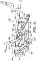
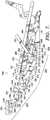
- the stop element 287is formed to extend from the footrest lock link 270 such that the lower contact edge 286 of the actuator plate 280 is adapted to contact the stop element 287 during adjustment of the seating unit from the closed position ( FIG. 6 ) to the extended position ( FIG. 7 ).
- ottoman assembly 250includes the front ottoman link 110, a rear ottoman link 120, a third ottoman link 130, a mid-ottoman bracket 140, first ottoman link 150, a second ottoman link 160, and a footrest bracket 170.
- Front ottoman link 110includes a first end 114 rotatably coupled to a front portion 402 of the seat-mounting link 400 at pivot 115. Further, the front ottoman link 110 includes the mid portion 112 pivotably coupled to the forward end 274 of the footrest lock link 270 at the pivot 275, the third ottoman link 130 at pivot 113, and a forward end 712 of a footrest drive link 710 at pivot 111.
- the front ottoman link 110also includes a second end 116 pivotably coupled to a lower end 152 of the first ottoman link 150 at pivot 117.
- Rear ottoman link 120includes a first end 122 rotatably coupled to the front portion 402 of the seat mounting link 400 at pivot 121, and a second end 124 pivotably coupled to a lower end 132 of the third ottoman link 130 at pivot 133.
- pivot 121 of the rear ottoman link 120is located rearward in relation to the pivot 115 of the front ottoman link 110.
- Third ottoman link 130includes the lower end 132 pivotably coupled to the second end 124 of the rear ottoman link 120 at the pivot 133, and an upper end 134 pivotably coupled to a mid portion 144 of the mid-ottoman bracket 140 at pivot 135. As best depicted in FIG.
- the mid-ottoman bracket 140includes a straight end 142 pivotably coupled to a lower end 162 of the second ottoman link 160 at pivot 141, the mid portion 144 is rotatably coupled to a mid portion 154 of the first ottoman link 150 at pivot 155 and pivotably coupled to the upper end 134 of the third ottoman link 130 at the pivot 135 (discussed above), and an angled end 146 that is typically connected to a stabilizer tube (not shown) that spans between the ottoman assembly 250 and an opposed ottoman assembly.
- the stabilizer tubemay assist supporting the leg-support ottoman 47 (see FIGS. 1-4 ).
- the first ottoman link 150includes the lower end 152 pivotably coupled to the second end 116 of the front ottoman link 110 at the pivot 117, the mid portion 154 pivotably coupled to the mid portion 144 of the mid-ottoman bracket 140 at the pivot 155, and an upper end 156 pivotably coupled to a first end 172 of the footrest bracket 170 at pivot 157 and includes a stop element 173.
- the stop element 173contacts a mid portion 166 of the second ottoman link 160 when the seating unit is adjusted to the extended position thereby resisting further extension of the ottoman assembly 250.
- Second ottoman link 160includes a lower end 162 pivotably coupled to the straight end 142 of the mid-ottoman bracket 140 at the pivot 141, an upper end 164 pivotably coupled to a mid portion 174 of the footrest bracket 170 at pivot 175, and the mid portion 166 that may contact the stop element 173.
- Footrest bracket 170includes the first end 172 rotatably coupled to the upper end 156 of the first ottoman bracket 150 at the pivot 157, and the mid portion 174 pivotably coupled to the upper end 164 of the second ottoman link 160 at the pivot 175.
- the footrest bracket 170assists in supporting the first foot-support ottoman 45 (see FIGS. 1-4 ) and is typically disposed in a generally horizontal orientation when in the extended position and the reclined position.
- occupantinitiates an adjustment from the closed position ( FIG. 6 ) to the extended position ( FIG 7 ).
- the occupantmay exert a manual rearward force 905 on the handle portion 281.
- the actuationmay be a force exerted on a release lever of a cable actuator, discussed below with reference to FIGS. 11 and 12 , or the actuation may be a control signal conveyed to a motor, discussed below with reference to FIGS. 15-17 .
- Rearward force 905 on the handle portion 281creates a torque on the actuator plate 280 about pivot 285.
- the torqueis transferred to the footrest lock link 270 upon the lower contact edge 286 of the actuator plate 280 contacting the stop element 287.
- This contactforwardly pushes the footrest lock link 270 as the lower contact edge 286 of the actuator plate 280 forwardly rotates about pivot 285. Accordingly, the forward push of the footrest lock link 270 triggers adjustment of the seating unit from the closed position to the extended position.
- a furniture designercan supply the seating unit with high legs, so that the seating unit resembles a traditional chair, or can lower the chassis of the seating unit to the underlying surface without creating an interference when adjusting the ottoman assembly 250. Because the ottoman assembly is hidden in the closed position, both the configurations discussed above are aesthetically pleasing as well as functional.
- Footrest lock link 270is drivably coupled to the front ottoman link 110 at pivot 275 such that forward and upward translation of the footrest lock link 270 initiates movement of the ottoman assembly 250 from the closed position to the extended position. That is, the front ottoman link 110 is rotated forward about the pivot 115 causing the ottoman assembly 250 to extend. Front ottoman link 110 is pivotably coupled to the rear ottoman link 120 by the third ottoman link 130. Accordingly, forward rotation of the front ottoman link 110 affects forward rotation of the rear ottoman link 120 about the pivot 121.
- the front ottoman link 110 and the rear ottoman link 120rotate in substantial parallel-spaced relation.
- the rotation of the front ottoman link 110 and the rear ottoman link 120generate upward movement of the first ottoman link 150 and the third ottoman link 130, respectively.
- the first and third ottoman links 150, 130operate in conjunction to raise and rotate the mid-ottoman bracket 140 to a generally horizontal orientation during their upward movement.
- the rotation of the mid-ottoman bracket 140 about pivot 155produces upward movement of the second ottoman link 160 via the pivot 141.
- the first and second ottoman links 150, 160operate in conjunction to raise and rotate the footrest bracket 170 to a generally horizontal orientation during their upward movement.
- the first foot-support ottoman 45(see FIGS. 1-4 ) supported by the footrest bracket 170 is movable from a position below the seat support surface to an extended, horizontally-orientated position. Retraction of the ottoman assembly is discussed below with reference to the seat-adjustment mechanism 700 of FIG. 8 .
- Extension-resistive device 277may be any device that creates a compressive force between two points.
- the extension-resistive device 277is an extension spring.
- the extension-resistive device 277is connected at one end to an aperture 401 in the seat-mounting link 400, and connected at another end to an aperture 276 in the footrest lock link 270.
- the extension-resistant device 277interconnects the seat-mounting link 400 to the footrest lock link 270 is a resistive relationship.
- the extension-resistive device 277defines a longitudinal extension-control axis 279.
- Over-center axis 900is a theoretical line derived from the direction of compressive force generated by the extension-resistant device 277.
- Over-center axis 900radially extends from the central longitudinal axis of the drive tube 300 and resides in perpendicular-spaced relation therewith.
- the over-center axis 900is disposed in parallel-spaced relation to the extension-control axis 279 defined by the extension-resistant device 277.
- the extension-resistive device 277resists motion of the ottoman assembly 250 in the extended position of FIG. 10 , and assists in collapsing the ottoman assembly 250 to the closed position of FIG. 9 incident to the pivot location 256 passing rearwardly across the over-center axis 900.
- extension-resistive device 277resists motion of the ottoman assembly 250 in the closed position of FIG. 9 , and assists in extending the ottoman assembly 250 to the extended position of FIG. 10 incident to the pivot location 256 passing forwardly across the over-center axis 900.
- the seat-adjustment mechanism 700provides for straight-line translation of the seat-mounting link 400 over the base plate 410, and includes the footrest drive link 710, the bell crank 720, a rear control link 730, a rear pivot link 740, and a roller system 750.
- the footrest drive link 710includes the forward end 712 pivotably connected to the front ottoman link 110 of the ottoman assembly 250 at the pivot 111, and a rearward end 714 pivotably connected to the bell crank 720 at pivot 715.
- Bell crank 720is rotatably coupled to seat-mounting link 400 at pivot 721 (see FIG. 13 ).
- the bell crank 720is pivotably coupled to a forward end 732 of the rear control link 730 at pivot 731 and a front control link 552 (see FIG. 13 ) at pivot 557.
- the rear control link 730includes a forward end 732 pivotably coupled to the bell crank 720 at the pivot 731 and a rearward end 734 pivotably coupled to a forward portion 744 of the rear pivot link 740 at pivot 745.
- Rear pivot link 740is a generally L-shaped plate that includes an upper end 742 rotatably coupled to the seat-mounting link 400 at pivot 743, the forward portion 744 pivotably coupled to the rear control link 730 at the pivot 745, and a rearward end 746 that is operably coupled to the roller system 750 at pivot 756.
- the roller system 750is configured to translate the seat-mounting link 400 over the base plate 410 during adjustment between the closed position, the extended position, and the reclined position while maintaining a consistent inclined orientation relationship therebetween.
- the seating support surface(discussed above) is biased at a particular inclination angle throughout adjustment.
- the roller system 750includes a wheel 755, and an inclined track 760.
- Wheel 755is rotationally disposed about the pivot 756 at the rearward end 746 of the rear pivot link 740.
- the wheel 755is rollably engaged to the inclined track 760.
- rollable engagementincludes fitting the wheel 755 within a pair of longitudinal slots 761 incorporated within the inclined track 750 such that the slots 761 both guide and retain the wheel 755.
- Inclined track 760is fixedly attached to the base plate 410 and is typically disposed in an inclined orientation.
- the inclined orientationdefines a trajectory of a straight-line motion path of the seat-mounting link 400 during translation.
- the inclined track 760includes a rear portion 762, a mid portion 764, and a front portion 766. Accordingly, when the seating unit is adjusted to the closed position, the wheel 755 is located within the rear portion 762. When in the extended position, the wheel 755 is located in the mid portion 764. And, when in the reclined position, the wheel 755 is located in the front portion 766.
- the seat-adjustment mechanism 700assists in extending the ottoman assembly 250.
- occupant weightproduces a substantially-vertical downward force 909 on the seat-mounting link 400 that is transferred to the rear pivot link 740.
- Rear pivot link 740is rotatable about the pivot 743 on the seat-mounting link 400, and is supported by the pivot 756 at the wheel 755. Accordingly, the downward force 909 produces a counter-clockwise torque at the rear pivot link 740, which rearwardly pulls the rear control link 730.
- a manual downward force 911 on a first foot-support ottoman(not shown) that is distributed to the footrest bracket 170.
- the manual downward force 911 on the footrest bracket 170causes the links 110, 120, 130, 150, and 160 to move downwardly and/or rotate in a counter-clockwise direction.
- the brackets 140 and 170are lowered and rotated in counter-clockwise fashion such that the ottomans 45 and 47 (see FIGS. 1-4 ) are adjusted from a generally horizontal orientation to a collapsed, generally-vertical orientation and are disposed beneath the seating support surface.
- extension-resistant device 277assists in collapsing the ottoman assembly 250.
- extension-resistive device 277assists in collapsing the ottoman assembly 250 to the closed position (of FIG. 9 ) incident to the pivot location 256 passing rearwardly across the over-center axis 900.
- the downward force 909 of a seated occupantproduces a torque at the rear pivot link 740 that continually promotes extending the ottoman assembly 250 to the open position.
- the collapsing force of extension-resistive device 277overcomes this occupant-generated tendency to extend, thereby facilitating adjusting the ottoman assembly 250 to closed position.
- FIGS. 13 and 14depict a side elevation view from an internal perspective of the linkage mechanism 100 in an extended position ( FIG. 13 ) and a reclined position ( FIG. 14 ), in accordance with an embodiment of the present invention.
- the recliner mechanism 500includes the back-mounting bracket 510, the back drive link 520, and the front lift assembly 550.
- recliner mechanism 500is adapted to recline the backrest 25 (see FIGS. 1-4 ) rearward while translating the seat-mounting link 400 upward and forward over the base plate 410. Accordingly, the zero-wall clearance capability is achieved.
- the zero-wall clearanceis demonstrated by a theoretical wall plane 955 defined by a rearmost edge 950 of the back-mounting bracket 510 in the extended position of FIG. 13 .
- Wall plane 955is further defined as being perpendicular to the underlying surface 960.
- the back-mounting bracket 510includes a back-support section 512 for receiving a rearward occupant force 907, a mid portion 514 that is rotatably coupled to the seat-mounting link 400 at pivot 515, and a drive section 516 pivotably coupled to rearward end 522 of the back drive link 520 at pivot 517.
- Back drive link 520includes the rearward end 522 coupled to the back-mounting bracket 510 at the pivot 517, and a forward end 524 pivotably coupled to a first end 534 of a front lift link 530 (of the front lift assembly 550) at pivot 525.
- Front lift assembly 550generally includes the front lift link 530, a front pivot link 540, and a front control link 552.
- Front lift link 530includes a mid portion 532 rotatably coupled to the seat-mounting link 400 at pivot 533, the first end 534 pivotably coupled to the front drive link 530 at the pivot 525, and a second end 536 pivotably coupled to a first end 542 of the front pivot link 540 at pivot 535.
- Front pivot link 540includes the first end 542 pivotably coupled to the front lift link 530 at the pivot 535, a mid portion 544 pivotably coupled to a first end 554 of the front control link 552 at pivot 545, and a second end 546 rotatably coupled to a forward end 411 of the base plate 410 at pivot 547.
- Front control link 552includes the first end 554 pivotably coupled to the front pivot link 540 at the pivot 545, and a second end 556 pivotably coupled to the bell crank 720 at pivot 557.
- the operation of the recliner mechanism 500will be discussed, in accordance with an embodiment of the present invention.
- the operator-initiated, rearward occupant force 907is received at back-support section 512 of the back-mounting bracket 510.
- the rearward occupant force 907should overcome a balance threshold in order to rearwardly bias the back-mounting bracket 510 thereby enabling movement from the extended position ( FIG. 13 ) to the reclined position ( FIG. 14 ).
- the balance thresholdis defined by a ratio of the rearward occupant force 907 on the backrest and the downward occupant weight 909 on the seat.
- the downward occupant weight 909forces the seat-mounting bracket 400 down, while the rearward occupant force 907 forces the seat-mounting bracket 400 up via the interconnection of the back-mounting bracket 510, the back drive link 520, the front lift assembly 550, and the base frame 410.
- the rearward occupant force 907rearwardly rotates the back-mounting bracket 510.
- the rearward rotationgenerates a torque about the pivot 515.
- the torqueis converted to a forward laterally-directed force through the back drive link 520.
- the back drive link 520acts as a single element that serves to transfer the laterally-directed force between the back-mounting bracket 510 and the front-lift assembly 550.
- the back drive link 520creates a counter-clockwise torque on the front lift link 530 about the pivot 533.
- Front lift link 530converts the counter-clockwise torque to a downward force directed through the front pivot link 540, which rotates about the forward end 411 of the base plate 410. This rotation enables the seat-mounting link 400 to be translated forward and upward in relation to the base plate 410 during adjustment from the extended position to the reclined position. That is, the seat remains biased in the inclination angle with respect to the chassis throughout adjustment.
- the front-lift assembly 550further includes a front control link 552 that controls the rotation of the front pivot link 540 about pivot 545.
- the front control link 552includes the first end 554 pivotably coupled to the front pivot link 540, and the second end 556 pivotably coupled to the bell crank 720.
- the ends 554 and 556establish a length of the front control link 552. During adjustment between the extended position to the reclined position, the length determines a distance of the upward translation of the seat-mounting link 400 in relation to the base plate 410.
- the back-mounting bracket 510Upon relieving the rearward occupant force 907 on the back-mounting bracket 510 below a balance threshold (e.g., by the occupant leaning forward), the back-mounting bracket 510 is allowed to forwardly bias.
- the downward occupant weight 909causes the front pivot link 540 to push forward on the front lift link 530 creating clockwise rotation thereof.
- the clockwise rotationtransfers a rearward laterally-directed force through the back-drive link 520 that acts to rotate the back-mounting bracket 510 in a counter-clockwise manner. That is, the laterally-directed force applied by the back-drive link 520 enables moving the back-mounting bracket 510 forward to a substantially upright orientation.
- a stop spacer(not shown) extending from the front lift link 530 resists continued rotation of the front lift link 530, upon contacting the seat-mounting link 400; thus, further forward inclination of the backrest when in the closed or the extended position is contained.
- Cable actuator assembly 850includes a handle bracket 852, a release handle 856, a pivot pin 858, and a cable assembly 861. Handle bracket 852 and release handle 856 are pivotably coupled by the pivot pin 858. Cable assembly 861 has a conduit 854, and a cable wire 860 with an actuation end 862 extending from the conduit 854 and fastened to an aperture 281 of the actuator plate 280. Cable wire 860 is allowed to move axially within the conduit 854 as is known to those of skill in the art.
- the cable wire 860is fixedly connected to the release handle 856 such that the cable wire 861 may be manipulated by moving the release handle 856 between a resting condition ( FIG. 11 ) and a trigger condition ( FIG. 12 ).
- the conduit 854is secured to the seat-mounting bracket 400 via a clamp-type fastener 862.
- the occupant of the seating unitmay exert a pulling force 906 on the release handle 856 to adjust the recliner mechanism 500 from the closed position ( FIG. 11 ) to the extended position ( FIG. 12 ).
- Pulling the release handle 856rotates the release handle 856 about pivot pin 858 switching from the resting condition to the trigger condition.
- This movementengages the cable wire 860 thereby pulling the cable wire 860 through conduit 854.
- footrest lock link 270is pushed forward, the footrest mechanism 200 is triggered to move from the closed position to the extended position, as more fully discussed above.
- the motor 450includes an elongated member 472, a drive piece 470 that translates longitudinally over the elongated member 472 under automated control, and a pair of pivot brackets 468 fixedly attached to the drive piece 470.
- the elongated memberincludes a first travel section 480 and a second travel section 490.
- the motor 450is pivotably coupled at a clevis-type fastener 462 to a motor-mount tube 460.
- the motor-mount tube 460is fixedly attached to the base plate 410.
- the drive tube 300is equipped with a drive-tube angle 466 attached to the drive tube 300 and a pair of L-shaped pivot brackets 464 that extend radially from the drive-tube angle 466.
- L-shaped pivot brackets 464 and the pivot brackets 468are pivotably coupled a pivot 469.
- the occupantmay provide an automated control to the motor 450 to adjust the seating unit between the closed position and the extended position.
- the motor 450traverses the drive piece 470 along the elongated member 472 within the first travel section 480 thereof.
- the drive piece 470 in conjunction with L-shaped pivot brackets 468create a torque at the pivot brackets 464 thereby rotatably adjusting the drive tube 300.
- the rotatable adjustmentactuates the footrest lock bracket (not shown) to either extend or collapse the footrest mechanism 200, as discussed above.
- the recliner mechanism 500is adjusted.
- the drive piece 470When traversing the second travel section 490, the drive piece 470, in conjunction with L-shaped pivot brackets 468, create a lateral thrust at the pivot brackets 464 thereby translating the drive tube 300.
- the lateral thrustpushes the seat-mounting link 400 (rotatably coupled to the drive tube 300) upward and forward in relation to the base plate 410, thereby adjusting the recliner mechanism 500 to reclined position, or pulls the seat-mounting link 400 downward and rearward in relation to the base plate 410, thereby adjusting the recliner mechanism 500 to the extended position, as discussed above.
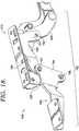
- the leg-extension assembly 180includes a mounting bracket 185, a drive bracket 190, and a flipper arm 195.
- Mounting bracket 185is fixedly attached to the footrest bracket 170.
- Drive bracket 190includes an angled end 191 pivotably coupled to the second ottoman link 160 at pivot 192, and a straight end 193 pivotably coupled to a coupling end 194 of the flipper arm 195.
- Flipper arm 195includes the coupled end rotatably coupled to the mounting bracket 185 at pivot 196, and pivotably coupled to the straight end 193 of the drive bracket 190 at pivot 197. In operation, the flipper arm 195 is rotated to a substantially horizontal orientation in the extended position. In particular, the drive bracket 190 is driven forward by the second ottoman link 160 when extending the ottoman assembly 250 from the closed position.
- the flipper arm 195is adapted to carry a second foot-support ottoman (not shown) such that when the flipper arm is in the extended position (i.e., orientated in a substantially horizontal disposition) the second foot-support ottoman is generally horizontal and forward of the first foot-support ottoman 45 (see FIGS. 1-4 ).
- linkage mechanism 100lends itself to enable the various links and brackets to be easily assembled and disassembled from the remaining components of the seating unit. Specifically the nature of the pivots and/or mounting locations, allows for use of quick-disconnect hardware, such as a knock-down fastener. Accordingly, rapid disconnection of components prior to shipping, or rapid connection in receipt, is facilitated.
Landscapes
- Health & Medical Sciences (AREA)
- Dentistry (AREA)
- General Health & Medical Sciences (AREA)
- Chairs For Special Purposes, Such As Reclining Chairs (AREA)
- Passenger Equipment (AREA)
Description
- Accordingly, the present invention seeks to provide a simplified, compact, linkage mechanism which can be adapted to essentially any type of seating unit. Linkage mechanisms for seating are known, as seen in
US4,099,776 which describes a control assembly for a reclining chair. However many seating units including linkage mechanisms still include limitations. - According to the invention the seating unit includes the following components: a backrest; a first foot-support ottoman; a chassis that has a pair of base plates in substantially parallel- spaced relation and at least one crossbeam spanning the base plates; a pair of seat-mounting links in substantially parallel-spaced relation, a seating support surface extending between the seat- mounting links; and a pair of the generally mirror- image linkage mechanisms that interconnect the base plates to the seat-mounting links. Additionally, the seat- mounting links are disposed in an inclined orientation in relation to the base plate. In operation, the linkage mechanisms are adapted to move between a closed position, an extended position, and a reclined position. According to the invention, the linkage mechanisms include a pair of ottoman assemblies that movably interconnect the first foot-support ottoman to the seat-mounting links, and a pair of roller systems. In particular, the roller systems are adapted to translate the seat-mounting links over the base plates via a roller and inclined track during adjustment between the closed position, the extended position, and the reclined position. According to the invention, the roller systems translate the seat-mounting links while maintaining their inclined orientation relationship to the base plate such that the seating support surface is biased at a particular inclination angle throughout adjustment and the backrest having a rearmost edge that defines a wall plane that is perpendicular to the underlying surface when the seating is moved to the extended position, when the seating unit is adjusted to the reclined position, the seat mounting links are translated forward and upward in relation to the base plates such that the rearmost edge of the backrest is located forward of the wall plane.
- In embodiments, the ottoman assembly includes a set of linkages that are adapted to collapse to the closed position such that the set of linkages are located below the seating support surface and above a lower surface of a crossbeam support. This collapsed configuration reduces the set of linkages to a compact size such that the seating unit can incorporate high legs (e.g., legs of a traditional chair) while still hiding the linkage mechanism in the closed position.
- In other embodiments, the seating unit includes a pair of opposed arms that each have an arm-support surface. The opposed arms are operably coupled to the seat- mounting links such that during adjustment between the closed position, the extended position, and the reclined position, the arm-support surfaces of the opposed arms are maintained in a consistent substantially-horizontal orientation.
- In yet another embodiment, the linkage mechanism further includes the following components: a pair of back- mounting brackets rotatably coupled to the seat- mounting links and fixedly attached to a backrest; a pair of back-drive links in generally laterally-spaced relation to the seat-mounting links and pivotably coupled to the back- mounting brackets; and a pair of front-lift assemblies rotatably coupled to the seat-mounting links. Generally, the front lift assemblies operably couple the back-drive links to the base plates. In operation, when adjusting between the extended and the reclined positions, the seat-mounting links are translated forward and upward in relation to the base plates which are directed by the front-lift assemblies. Accordingly, the seat-mounting links remain biased in a particular inclination angle with respect to the chassis throughout adjustment.
- Still further, in another embodiment of the present invention, the linkage mechanism has footrest mechanisms. Generally, the footrest mechanisms include the following elements: a pair of footrest lock brackets that are fixedly attached to extending ends of a drive tube; a pair of footrest lock links that are pivotably coupled footrest lock brackets; a pair of extension-resistant devices interconnecting the seat-mounting links to the footrest lock links; and a pair of over-center axes that radially extend from a longitudinal axis of the drive tube. In one instance, the over-center axes reside in perpendicular-spaced relation with the extension-resistive devices. In use, the extension-resistive devices resist motion of the ottoman assemblies in the extended position and assist collapse of the ottoman assemblies to the closed position, incident to the pivot locations passing rearwardly across the over-center axes.
- In the accompanying drawings which form a part of the specification and which are to be read in conjunction therewith, and in which like reference numerals are used to indicate like parts in the various views:
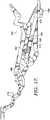
FIG. 1 is a diagrammatic lateral view of a seating unit in a closed position, in accordance with an embodiment of the present invention;FIG. 2 is a view similar toFIG. 1 , but in an extended position, in accordance with an embodiment of the present invention;FIG. 3 is a view similar toFIG. 1 , but in a reclined position with opposed arms attached to a stationary base, in accordance with an embodiment of the present invention;FIG. 4 is a view similar toFIG. 1 , but in the reclined position with the opposed arms attached to a linkage mechanism, in accordance with an embodiment of the present invention;FIG. 5 is a partial perspective view of the linkage mechanism in the extended position, in accordance with an embodiment of the present invention;FIG. 6 is a side elevation view from an external perspective of a linkage mechanism in a closed position, in accordance with an embodiment of the present invention;FIG. 7 is a view similar toFIG. 6 , but in an extended position, in accordance with an embodiment of the present invention;FIG. 8 is a view similar toFIG. 6 , but in a fully reclined position, in accordance with an embodiment of the present invention;FIG. 9 is a view similar toFIG. 6 , but with an extension-resistive device and showing an over-center axis, in accordance with an embodiment of the present invention;FIG. 10 is a view similar toFIG. 9 , but in the extended position, in accordance with an embodiment of the present invention;FIG. 11 is a view similar toFIG. 6 , but with a cable actuator assembly, in accordance with an embodiment of the present invention;FIG. 12 is a view similar toFIG. 11 , but in an extended position, in accordance with an embodiment of the present invention;FIG. 13 is a side elevation view from an internal perspective of the linkage mechanism in an extended position, in accordance with an embodiment of the present invention;FIG. 14 is a view similar toFIG. 13 , but in a fully reclined position, in accordance with an embodiment of the present invention;FIG. 15 is view similar toFIG. 13 , but in the closed position with a motor actuator mechanism, in accordance with an embodiment of the present invention;FIG. 16 is a view similar toFIG. 15 , but in an extended position, in accordance with an embodiment of the present invention;FIG. 17 is a view similar toFIG. 15 , but in a fully reclined position, in accordance with an embodiment of the present invention; andFIG. 18 is an enlarged partial side elevation view of a linkage mechanism in an extended position with a leg-extension assembly, in accordance with an embodiment of the present invention.FIGS. 1-4 illustrate aseating unit 10.Seating unit 10 has aseat 15, abackrest 25,legs 26, alinkage mechanism 100, a first foot-support ottoman 45, a leg-support ottoman 47, astationary base 35, and a pair ofopposed arms 55.Stationary base 35 has aforward section 52, arearward section 54 and is supported by thelegs 26, where thelegs 26 support thestationary base 35 and raise it above an underlying surface (not shown). In addition, thestationary base 35 supports theseat 15 via thelinkage mechanism 100 that is generally disposed between the pair ofopposed arms 55, and therearward section 54.Seat 15 may comprise a T-cushion style seat that is moveable over thestationary base 35 during adjustment of theseating unit 10. In embodiments, the T-cushion style seat is moveable according to the arrangement of thelinkage mechanism 100 such that no portion of the T-cushion style seat interferes with theopposed arms 55 throughout adjustment.- Opposed
arms 55 are laterally spaced and have an arm-support surface 57 that is orientated substantially horizontally. In one embodiment, the pair ofopposed arms 55 are attached to the stationary base via intervening members, as illustrated inFIG. 3 . In another embodiment, the pair of opposed arms are attached to thelinkage mechanism 100, as illustrated inFIG. 4 . Thebackrest 25 extends from therearward section 54 of thestationary base 35 and is rotatably coupled to thelinkage mechanism 100, typically proximate to the arm-support surface 57. First foot-support ottoman 45 and the leg-support ottoman 47 are moveably supported by thelinkage mechanism 100. Thelinkage mechanism 100 is arranged to articulably actuate and control movement of theseat 15, theback 25, and theottomans FIGS. 1-4 , as more fully described below. - As shown in
FIGS. 1-4 , theseating unit 10 is adjustable to three basic positions: a closedposition 20, an extended position 30 (i.e., TV position), and thereclined position 40.FIG. 1 depicts theseating unit 10 adjusted to the closedposition 20, which is a normal non-reclined sitting position with theseat 15 in a generally horizontal position and theback 25 generally upright and in a substantial perpendicular biased relation to theseat 15. In particular, theseat 15 is disposed in a slightly inclined orientation relative to thestationary base 35. This inclined orientation is maintained throughout adjustment of theseating unit 10. In addition, when adjusted to the closedposition 20, theottomans seat 15. - Turning to
FIG. 2 , the extendedposition 30, or TV position, will now be described. When theseating unit 10 is adjusted to the extended position, the leg support ottoman 47 and the first foot-support ottoman 45 are extended forward of theforward section 52 of thestationary base 35 and disposed generally horizontal. However, thebackrest 25 remains substantially perpendicular to theseat 15 and will not encroach an adjacent wall, and theseat 15 is maintained in the inclined orientation relative to thestationary base 35. Thus, the configuration of theseating unit 10 in the extendedposition 30 provides an occupant a reclined TV position while providing space-saving utility. Typically, theseat 15 is translated slightly forward and upward relativestationary base 35. This independent movement of theseat 15 allows a T-cushion style seat to be used as theseat 15. Generally, the T-cushion style seat extends forward over theforward section 52 and both between and in front of opposedarms 55. FIGS. 3 and 4 depict the reclinedposition 40, in which theseating unit 10 is fully reclined. With reference toFIG. 3 , theopposed arms 55 are attached to thestationary base 35. In another embodiment, thelegs 26 may extend downward from the opposedarms 55, instead of being attached to thestationary base 35. Accordingly, the arm-support surfaces 57 are maintained in substantially horizontal orientation. Thebackrest 25 is rotated rearwardly by thelinkage mechanism 100 and biased in rearward inclination angle. The rearward inclination angle is an obtuse angle in relation to theseat 15. However, the rearward inclination angle of thebackrest 25 is offset by a forward and upward translation of theseat 15 as controlled by thelinkage mechanism 100. This is in contrast to other reclining chairs with 3-position mechanisms, which cause a backrest to move rearward, thereby requiring that the reclining chair be positioned a considerable distance from an adjacent rear wall. Thus, the translation of theseat 15 in the present invention allows for zero-wall clearance, which is a space-saving utility that permits positioning theseating unit 10 in close proximity to an adjacent rear wall. In embodiments, theottomans extended position 30.- In another embodiment, as illustrated in
FIG. 4 , theopposed arms 55 translate forward and rearward relative to thestationary base 35 during adjustment. In one embodiment, the translation of the opposedarms 55 is facilitated by thelinkage mechanism 100 such that the arm-support surfaces 57 are maintained in substantially horizontal orientation. Accordingly, thebackrest 25 is rotated over the arm-support surfaces 57 to a rearward inclination angle thereby providing a pivot-over-arm feature. This feature allows a furniture designer to provide thebackrest 25 with winged backs that will not interfere with theopposed arms 55 during adjustment of theseating unit 10. - Turning now to
FIG. 5 , thelinkage mechanism 100 will now be discussed in detail. Initially,linkage mechanism 100 comprises a plurality of linkages that are arranged to actuate and control movement of the seating unit during movement between the closed, the extended, and the reclined position. These linkages may be pivotably interconnected. It is understood and appreciated that the pivotable couplings (illustrated as pivot points in the figures) between these linkages can take a variety of configurations, such as pivot pins, bearings, traditional mounting hardware, rivets, bolt and nut combinations, or any other suitable fasteners which are well-known in the furniture-manufacturing industry. Further, the shapes of the linkages and the brackets may vary as desired, as may the locations of certain pivot points. It will be understood that when a linkage is referred to as being pivotably "coupled" to, "interconnected" with, "attached" on, etc., another element (e.g., linkage, bracket, frame, and the like), it is contemplated that the linkage and elements may be in direct contact with each other, or other elements (such as intervening elements) may also be present. - Generally, the
linkage mechanism 100 guides the rotational movement of thebackrest 25 and the translational movement of theseat 15, in relation to the stationary base 35 (seeFIGS. 1-4 ). In an exemplary configuration, these movements are controlled by a pair of essentially mirror-image linkage mechanisms (one of which is shown herein and indicated by reference numeral 100), which comprise an arrangement of pivotably interconnected linkages. The linkage mechanisms are disposed in opposing-facing relation about a longitudinally-extending plane that bisects theseating unit 10 between the pair of opposed arms 55 (seeFIGS. 1-4 ). As such, the ensuing discussion will focus on only one of thelinkage mechanisms 100, with the content being equally applied to the other linkage assembly. - With continued reference to
FIG. 5 , a partial perspective view of thelinkage mechanism 100 in the extended position is shown, in accordance with an embodiment of the present invention. In embodiments, thelinkage mechanism 100 includes afootrest mechanism 200, a seat-mountinglink 400, abase plate 410, arecliner mechanism 500, and a seat-adjustment mechanism 700.Footrest mechanism 200 is comprised of a plurality of links arranged to extend and collapse theottomans 45 and 47 (seeFIGS. 1-4 ) during adjustment of the seating unit from the extended position to the closed position, respectively. In addition, thefootrest mechanism 200 includes anottoman assembly 250 and anactuation assembly 260, as more fully discussed below with reference toFIGS. 6-8 . Seat-mountinglink 400 is configured to fixedly mount to a seat (e.g., T-cushion style seat) and in conjunction with an opposed seat-mounting link, define a seat support surface (not shown). In embodiments, the seat support surface extends between the pair of seat-mounting links and is disposed in a particular inclination angle throughout adjustment of the seating unit. In one instance, the seat-mountinglink 400 is maintained in an inclined orientation relationship to thebase plate 410 during adjustment between the closed, the extended, and the reclined positions. - Additionally, the seat-mounting
link 400 includes anaperture 402 configured to receive adrive tube 300. In particular, thedrive tube 300 includes extending ends 302, each formed to protrude through arespective aperture 402 of a respective seat-mountinglink 400. In embodiments, one of the extending ends 302 is rotatably coupled to thebase plate 410 enabling thedrive tube 300 to revolve about a central longitudinal axis (not shown) defined thereby. Base plate 410 is typically fixedly mounted to a chassis and/or held in position by a set of crossbeams that span between thebase plate 410 and a corresponding base plate of an mirror-image linkage assembly. In embodiments, the set of crossbeams are square metal tubing that attach to alower edge 412 of thebase plate 410. Generally, thebase plate 410, the seat-mountinglink 400, and the plurality of links that comprise thelinkage mechanism 100 are formed from metal stock, such as stamped, formed steel. However, it should be understood and appreciated that any suitable rigid or sturdy material known in the furniture-manufacturing industry may be used as well.Recliner mechanism 500 includes back mountingbracket 510, aback drive link 520, and afront lift assembly 550. Generally,recliner mechanism 500 is adapted to recline the backrest 25 (seeFIGS. 1-4 ) rearward while translating the seat-mountinglink 400 upward and forward over thebase plate 410. Accordingly, the zero-wall clearance capability is achieved. The components and operation of the recliner mechanism is discussed more fully below with reference toFIGS. 13 and14 . Seat-adjustment mechanism 700 includes several links, as discussed more fully below, and aroller system 750. Generally, the seat-adjustment mechanism 700 facilitates translating the seat-mountinglink 400 in a substantially straight-line path above thebase plate 410.- With reference to
FIGS. 6-8 , thefootrest mechanism 200 will now be discussed. As described above, thefootrest mechanism 200 includes theottoman assembly 250 and theactuation assembly 260. As best shown inFIG. 7 , theactuation assembly 260 includes afootrest lock bracket 262, afootrest lock link 270, and anactuator plate 280.Footrest lock bracket 262 includes afirst end 266 that is fixedly attached to the extendingend 302 of the drive tube 300 (seeFIG. 5 ), and asecond end 268 that is pivotably coupled to arearward end 272 of thefootrest lock link 270. The pivotable couple is made atpivot location 256 and is discussed more fully below with reference toFIGS. 9 and 10 . Footrest lock link 270 includes therearward end 272 pivotably coupled to thefootrest lock bracket 262, and aforward end 274 pivotably coupled atpivot 275 to a mid portion 112 of a front ottoman link 110 of theottoman assembly 250.Actuator plate 280 includes anupper end 282, amid portion 284 rotatably coupled to the seat-mountinglink 400 atpivot 285, and alower contact edge 286. As depicted inFIGS. 6-8 , ahandle portion 281 extends from theupper end 282 of theactuator plate 280, where thehandle portion 281 is configured to receive an actuation from an occupant to adjust the seating unit from the closed position to the extended position. As will be demonstrated below, various other configurations (besides the handle portion 281) may be provided to receive an actuation from an occupant. - In embodiments, the
footrest lock link 270 further includes amid portion 273 that has astop element 287 disposed thereon. Thestop element 287 is formed to extend from the footrest lock link 270 such that thelower contact edge 286 of theactuator plate 280 is adapted to contact thestop element 287 during adjustment of the seating unit from the closed position (FIG. 6 ) to the extended position (FIG. 7 ). - As seen in
FIG. 7 ,ottoman assembly 250 includes thefront ottoman link 110, arear ottoman link 120, athird ottoman link 130, amid-ottoman bracket 140,first ottoman link 150, asecond ottoman link 160, and afootrest bracket 170.Front ottoman link 110 includes afirst end 114 rotatably coupled to afront portion 402 of the seat-mountinglink 400 atpivot 115. Further, thefront ottoman link 110 includes the mid portion 112 pivotably coupled to theforward end 274 of the footrest lock link 270 at thepivot 275, thethird ottoman link 130 atpivot 113, and aforward end 712 of afootrest drive link 710 atpivot 111. Thefront ottoman link 110 also includes asecond end 116 pivotably coupled to alower end 152 of thefirst ottoman link 150 atpivot 117.Rear ottoman link 120 includes afirst end 122 rotatably coupled to thefront portion 402 of theseat mounting link 400 atpivot 121, and asecond end 124 pivotably coupled to alower end 132 of thethird ottoman link 130 atpivot 133. In an exemplary embodiment, pivot 121 of therear ottoman link 120 is located rearward in relation to thepivot 115 of thefront ottoman link 110. Third ottoman link 130 includes thelower end 132 pivotably coupled to thesecond end 124 of therear ottoman link 120 at thepivot 133, and anupper end 134 pivotably coupled to amid portion 144 of themid-ottoman bracket 140 atpivot 135. As best depicted inFIG. 13 , themid-ottoman bracket 140 includes astraight end 142 pivotably coupled to alower end 162 of thesecond ottoman link 160 atpivot 141, themid portion 144 is rotatably coupled to amid portion 154 of thefirst ottoman link 150 atpivot 155 and pivotably coupled to theupper end 134 of thethird ottoman link 130 at the pivot 135 (discussed above), and anangled end 146 that is typically connected to a stabilizer tube (not shown) that spans between theottoman assembly 250 and an opposed ottoman assembly. The stabilizer tube may assist supporting the leg-support ottoman 47 (seeFIGS. 1-4 ).- With reference to
FIGS. 7 and13 , thefirst ottoman link 150 includes thelower end 152 pivotably coupled to thesecond end 116 of thefront ottoman link 110 at thepivot 117, themid portion 154 pivotably coupled to themid portion 144 of themid-ottoman bracket 140 at thepivot 155, and anupper end 156 pivotably coupled to afirst end 172 of thefootrest bracket 170 atpivot 157 and includes astop element 173. In operation, thestop element 173 contacts amid portion 166 of thesecond ottoman link 160 when the seating unit is adjusted to the extended position thereby resisting further extension of theottoman assembly 250.Second ottoman link 160 includes alower end 162 pivotably coupled to thestraight end 142 of themid-ottoman bracket 140 at thepivot 141, anupper end 164 pivotably coupled to amid portion 174 of thefootrest bracket 170 atpivot 175, and themid portion 166 that may contact thestop element 173. Footrest bracket 170 includes thefirst end 172 rotatably coupled to theupper end 156 of thefirst ottoman bracket 150 at thepivot 157, and themid portion 174 pivotably coupled to theupper end 164 of thesecond ottoman link 160 at thepivot 175. In an exemplary embodiment, thefootrest bracket 170 assists in supporting the first foot-support ottoman 45 (seeFIGS. 1-4 ) and is typically disposed in a generally horizontal orientation when in the extended position and the reclined position.- The operation of the
footrest mechanism 200 will now be discussed with reference toFIGS. 6-8 . Initially, occupant initiates an adjustment from the closed position (FIG. 6 ) to the extended position (FIG 7 ). In an exemplary embodiment the occupant may exert a manualrearward force 905 on thehandle portion 281. In other embodiments the actuation may be a force exerted on a release lever of a cable actuator, discussed below with reference toFIGS. 11 and 12 , or the actuation may be a control signal conveyed to a motor, discussed below with reference toFIGS. 15-17 .Rearward force 905 on thehandle portion 281 creates a torque on theactuator plate 280 aboutpivot 285. The torque is transferred to the footrest lock link 270 upon thelower contact edge 286 of theactuator plate 280 contacting thestop element 287. This contact forwardly pushes the footrest lock link 270 as thelower contact edge 286 of theactuator plate 280 forwardly rotates aboutpivot 285. Accordingly, the forward push of the footrest lock link 270 triggers adjustment of the seating unit from the closed position to the extended position. - The forward push at the
stop element 287 upwardly and forwardly translates thefootrest lock link 270 causing a forwardly directed force at both thepivot 275 and thepivot location 256. Unlike traditional 4-bar extension mechanisms, the lateral force provided by the user is directed to thefront ottoman link 110, as opposed to a rear link. Thus, this configuration enables a significant extension of theottoman assembly 250, but also, a compact collapsed size of theottoman assembly 250 when in the closed position. This compact collapsed size enables theottoman assembly 250 to be located below the seating support surface and above a lower surface of at least one crossbeam (discussed above) when in the closed position. By folding into this compact collapsed size, theottoman assembly 250 is hidden within a chassis, or stationary base, of the seating unit. As such, a furniture designer can supply the seating unit with high legs, so that the seating unit resembles a traditional chair, or can lower the chassis of the seating unit to the underlying surface without creating an interference when adjusting theottoman assembly 250. Because the ottoman assembly is hidden in the closed position, both the configurations discussed above are aesthetically pleasing as well as functional. - The force at the
pivot location 256 pulls thesecond end 268 of thefootrest lock bracket 262 forward thereby rotating the drive tube 300 (seeFIG. 5 ) clockwise. Footrest lock link 270 is drivably coupled to thefront ottoman link 110 atpivot 275 such that forward and upward translation of thefootrest lock link 270 initiates movement of theottoman assembly 250 from the closed position to the extended position. That is, thefront ottoman link 110 is rotated forward about thepivot 115 causing theottoman assembly 250 to extend.Front ottoman link 110 is pivotably coupled to therear ottoman link 120 by thethird ottoman link 130. Accordingly, forward rotation of thefront ottoman link 110 affects forward rotation of therear ottoman link 120 about thepivot 121. Generally, as a result of the configuration of thepivots front ottoman link 110 and therear ottoman link 120 rotate in substantial parallel-spaced relation. The rotation of thefront ottoman link 110 and therear ottoman link 120 generate upward movement of thefirst ottoman link 150 and thethird ottoman link 130, respectively. The first andthird ottoman links mid-ottoman bracket 140 to a generally horizontal orientation during their upward movement. The rotation of themid-ottoman bracket 140 aboutpivot 155 produces upward movement of thesecond ottoman link 160 via thepivot 141. The first and second ottoman links 150, 160, operate in conjunction to raise and rotate thefootrest bracket 170 to a generally horizontal orientation during their upward movement. Accordingly, the first foot-support ottoman 45 (seeFIGS. 1-4 ) supported by thefootrest bracket 170 is movable from a position below the seat support surface to an extended, horizontally-orientated position. Retraction of the ottoman assembly is discussed below with reference to the seat-adjustment mechanism 700 ofFIG. 8 . - Referring now to
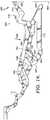
FIGS. 9 and 10 , an extension-resistive device 277 and anover-center axis 900 is illustrated, in accordance with an embodiment of the present invention. Extension-resistive device 277 may be any device that creates a compressive force between two points. In an exemplary embodiment, the extension-resistive device 277 is an extension spring. Typically, the extension-resistive device 277 is connected at one end to anaperture 401 in the seat-mountinglink 400, and connected at another end to anaperture 276 in thefootrest lock link 270. Accordingly, the extension-resistant device 277 interconnects the seat-mountinglink 400 to thefootrest lock link 270 is a resistive relationship. In addition, the extension-resistive device 277 defines a longitudinal extension-control axis 279. Over-center axis 900 is a theoretical line derived from the direction of compressive force generated by the extension-resistant device 277.Over-center axis 900 radially extends from the central longitudinal axis of thedrive tube 300 and resides in perpendicular-spaced relation therewith. In addition, theover-center axis 900 is disposed in parallel-spaced relation to the extension-control axis 279 defined by the extension-resistant device 277. Generally, the extension-resistive device 277 resists motion of theottoman assembly 250 in the extended position ofFIG. 10 , and assists in collapsing theottoman assembly 250 to the closed position ofFIG. 9 incident to thepivot location 256 passing rearwardly across theover-center axis 900. Alternatively, the extension-resistive device 277 resists motion of theottoman assembly 250 in the closed position ofFIG. 9 , and assists in extending theottoman assembly 250 to the extended position ofFIG. 10 incident to thepivot location 256 passing forwardly across theover-center axis 900.- Returning to
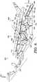
FIG. 8 , the seat-adjustment mechanism 700 will now be discussed in accordance with an embodiment of the present invention. As discussed above, the seat-adjustment mechanism 700 provides for straight-line translation of the seat-mountinglink 400 over thebase plate 410, and includes thefootrest drive link 710, the bell crank 720, arear control link 730, arear pivot link 740, and aroller system 750. In particular, thefootrest drive link 710 includes theforward end 712 pivotably connected to the front ottoman link 110 of theottoman assembly 250 at thepivot 111, and arearward end 714 pivotably connected to the bell crank 720 atpivot 715. Bell crank 720 is rotatably coupled to seat-mountinglink 400 at pivot 721 (seeFIG. 13 ). In addition, the bell crank 720 is pivotably coupled to aforward end 732 of the rear control link 730 atpivot 731 and a front control link 552 (seeFIG. 13 ) atpivot 557. Returning toFIG. 8 , the rear control link 730 includes aforward end 732 pivotably coupled to the bell crank 720 at thepivot 731 and arearward end 734 pivotably coupled to aforward portion 744 of therear pivot link 740 atpivot 745.Rear pivot link 740 is a generally L-shaped plate that includes anupper end 742 rotatably coupled to the seat-mountinglink 400 atpivot 743, theforward portion 744 pivotably coupled to the rear control link 730 at thepivot 745, and arearward end 746 that is operably coupled to theroller system 750 atpivot 756. - In embodiments, the
roller system 750 is configured to translate the seat-mountinglink 400 over thebase plate 410 during adjustment between the closed position, the extended position, and the reclined position while maintaining a consistent inclined orientation relationship therebetween. As such, the seating support surface (discussed above) is biased at a particular inclination angle throughout adjustment. Generally, theroller system 750 includes awheel 755, and aninclined track 760.Wheel 755 is rotationally disposed about thepivot 756 at therearward end 746 of therear pivot link 740. In addition, thewheel 755 is rollably engaged to theinclined track 760. In one embodiment, rollable engagement includes fitting thewheel 755 within a pair oflongitudinal slots 761 incorporated within theinclined track 750 such that theslots 761 both guide and retain thewheel 755.Inclined track 760 is fixedly attached to thebase plate 410 and is typically disposed in an inclined orientation. In one instance, the inclined orientation defines a trajectory of a straight-line motion path of the seat-mountinglink 400 during translation. Additionally, theinclined track 760 includes arear portion 762, amid portion 764, and afront portion 766. Accordingly, when the seating unit is adjusted to the closed position, thewheel 755 is located within therear portion 762. When in the extended position, thewheel 755 is located in themid portion 764. And, when in the reclined position, thewheel 755 is located in thefront portion 766. - In operation, as seen in
FIG. 8 , upon moving thepivot location 256 forwardly across the over-center axis 900 (seeFIGS. 9 and 10 ), typically caused by rotation of theactuator plate 280, the seat-adjustment mechanism 700 assists in extending theottoman assembly 250. In particular, as the occupant occupies the seat unit, occupant weight produces a substantially-verticaldownward force 909 on the seat-mountinglink 400 that is transferred to therear pivot link 740.Rear pivot link 740 is rotatable about thepivot 743 on the seat-mountinglink 400, and is supported by thepivot 756 at thewheel 755. Accordingly, thedownward force 909 produces a counter-clockwise torque at therear pivot link 740, which rearwardly pulls therear control link 730. This rearward pull is transferred to the bell crank 720 causing a forward rotation at thepivot 715 which forwardly and upwardly translates thefootrest drive link 710. The translation of thefootrest drive link 710 acts on thepivot 111 located on thefront ottoman link 110, thereby driving theottoman assembly 250 to the extended position. - Conversely, as seen in
FIGS. 6-8 , adjustment from the extended position to the closed position is initiated by a manualdownward force 911 on a first foot-support ottoman (not shown) that is distributed to thefootrest bracket 170. In a manner that is reverse to the steps discussed above with reference to operation of thefootrest mechanism 200, the manualdownward force 911 on thefootrest bracket 170 causes thelinks brackets ottomans 45 and 47 (seeFIGS. 1-4 ) are adjusted from a generally horizontal orientation to a collapsed, generally-vertical orientation and are disposed beneath the seating support surface. - In addition, upon moving the
pivot location 256 rearwardly (seeFIGS. 9 and 10 ), the extension-resistant device 277 assists in collapsing theottoman assembly 250. In particular, as discussed above, extension-resistive device 277 assists in collapsing theottoman assembly 250 to the closed position (ofFIG. 9 ) incident to thepivot location 256 passing rearwardly across theover-center axis 900. Thedownward force 909 of a seated occupant produces a torque at therear pivot link 740 that continually promotes extending theottoman assembly 250 to the open position. However, the collapsing force of extension-resistive device 277 overcomes this occupant-generated tendency to extend, thereby facilitating adjusting theottoman assembly 250 to closed position. - Referring to
FIGS. 13 and14 , therecliner mechanism 500 will now be discussed.FIGS. 13 and14 depict a side elevation view from an internal perspective of thelinkage mechanism 100 in an extended position (FIG. 13 ) and a reclined position (FIG. 14 ), in accordance with an embodiment of the present invention. As briefly discussed above, therecliner mechanism 500 includes the back-mountingbracket 510, theback drive link 520, and thefront lift assembly 550. Generally,recliner mechanism 500 is adapted to recline the backrest 25 (seeFIGS. 1-4 ) rearward while translating the seat-mountinglink 400 upward and forward over thebase plate 410. Accordingly, the zero-wall clearance capability is achieved. The zero-wall clearance is demonstrated by atheoretical wall plane 955 defined by arearmost edge 950 of the back-mountingbracket 510 in the extended position ofFIG. 13 .Wall plane 955 is further defined as being perpendicular to theunderlying surface 960. When the seating unit is adjusted to the reclined position ofFIG. 14 , the seat-mountinglink 400 is translated forward and upward in relation to thebase plate 410, as directed by therecliner mechanism 500, such that therearmost edge 950 is located forward of thewall plane 955. - In particular, the back-mounting
bracket 510 includes a back-support section 512 for receiving arearward occupant force 907, amid portion 514 that is rotatably coupled to the seat-mountinglink 400 atpivot 515, and adrive section 516 pivotably coupled torearward end 522 of theback drive link 520 atpivot 517. Back drive link 520 includes therearward end 522 coupled to the back-mountingbracket 510 at thepivot 517, and aforward end 524 pivotably coupled to afirst end 534 of a front lift link 530 (of the front lift assembly 550) atpivot 525.Front lift assembly 550 generally includes thefront lift link 530, afront pivot link 540, and afront control link 552.Front lift link 530 includes amid portion 532 rotatably coupled to the seat-mountinglink 400 atpivot 533, thefirst end 534 pivotably coupled to thefront drive link 530 at thepivot 525, and asecond end 536 pivotably coupled to afirst end 542 of thefront pivot link 540 atpivot 535.Front pivot link 540 includes thefirst end 542 pivotably coupled to the front lift link 530 at thepivot 535, amid portion 544 pivotably coupled to afirst end 554 of the front control link 552 atpivot 545, and asecond end 546 rotatably coupled to aforward end 411 of thebase plate 410 atpivot 547. Front control link 552 includes thefirst end 554 pivotably coupled to thefront pivot link 540 at thepivot 545, and asecond end 556 pivotably coupled to the bell crank 720 atpivot 557. - With continued reference to
FIGS. 13 and14 , the operation of therecliner mechanism 500 will be discussed, in accordance with an embodiment of the present invention. Initially, the operator-initiated,rearward occupant force 907 is received at back-support section 512 of the back-mountingbracket 510. In one embodiment, therearward occupant force 907 should overcome a balance threshold in order to rearwardly bias the back-mountingbracket 510 thereby enabling movement from the extended position (FIG. 13 ) to the reclined position (FIG. 14 ). Essentially, the balance threshold is defined by a ratio of therearward occupant force 907 on the backrest and thedownward occupant weight 909 on the seat. That is, thedownward occupant weight 909 forces the seat-mountingbracket 400 down, while therearward occupant force 907 forces the seat-mountingbracket 400 up via the interconnection of the back-mountingbracket 510, theback drive link 520, thefront lift assembly 550, and thebase frame 410. Incident to overcoming the balance threshold (e.g., by the occupant leaning backward), therearward occupant force 907 rearwardly rotates the back-mountingbracket 510. The rearward rotation generates a torque about thepivot 515. The torque is converted to a forward laterally-directed force through theback drive link 520. As such, theback drive link 520 acts as a single element that serves to transfer the laterally-directed force between the back-mountingbracket 510 and the front-lift assembly 550. In particular, theback drive link 520 creates a counter-clockwise torque on the front lift link 530 about thepivot 533. Front lift link 530 converts the counter-clockwise torque to a downward force directed through thefront pivot link 540, which rotates about theforward end 411 of thebase plate 410. This rotation enables the seat-mountinglink 400 to be translated forward and upward in relation to thebase plate 410 during adjustment from the extended position to the reclined position. That is, the seat remains biased in the inclination angle with respect to the chassis throughout adjustment. - In embodiments, the front-
lift assembly 550 further includes a front control link 552 that controls the rotation of thefront pivot link 540 aboutpivot 545. In particular, thefront control link 552 includes thefirst end 554 pivotably coupled to thefront pivot link 540, and thesecond end 556 pivotably coupled to thebell crank 720. The ends 554 and 556 establish a length of thefront control link 552. During adjustment between the extended position to the reclined position, the length determines a distance of the upward translation of the seat-mountinglink 400 in relation to thebase plate 410. - Upon relieving the
rearward occupant force 907 on the back-mountingbracket 510 below a balance threshold (e.g., by the occupant leaning forward), the back-mountingbracket 510 is allowed to forwardly bias. In particular, thedownward occupant weight 909 causes thefront pivot link 540 to push forward on the front lift link 530 creating clockwise rotation thereof. The clockwise rotation transfers a rearward laterally-directed force through the back-drive link 520 that acts to rotate the back-mountingbracket 510 in a counter-clockwise manner. That is, the laterally-directed force applied by the back-drive link 520 enables moving the back-mountingbracket 510 forward to a substantially upright orientation. In one instance, a stop spacer (not shown) extending from thefront lift link 530 resists continued rotation of thefront lift link 530, upon contacting the seat-mountinglink 400; thus, further forward inclination of the backrest when in the closed or the extended position is contained. - As shown in
FIGS. 11 and 12 , another embodiment for creating the actuation at theactuator plate 280 will now be discussed. This embodiment includes is acable actuator assembly 850.Cable actuator assembly 850 includes ahandle bracket 852, arelease handle 856, apivot pin 858, and acable assembly 861.Handle bracket 852 and release handle 856 are pivotably coupled by thepivot pin 858.Cable assembly 861 has aconduit 854, and acable wire 860 with anactuation end 862 extending from theconduit 854 and fastened to anaperture 281 of theactuator plate 280.Cable wire 860 is allowed to move axially within theconduit 854 as is known to those of skill in the art. Further, thecable wire 860 is fixedly connected to the release handle 856 such that thecable wire 861 may be manipulated by moving the release handle 856 between a resting condition (FIG. 11 ) and a trigger condition (FIG. 12 ). In embodiments, theconduit 854 is secured to the seat-mountingbracket 400 via a clamp-type fastener 862. - In use, the occupant of the seating unit may exert a pulling
force 906 on therelease handle 856 to adjust therecliner mechanism 500 from the closed position (FIG. 11 ) to the extended position (FIG. 12 ). Pulling therelease handle 856 rotates the release handle 856 aboutpivot pin 858 switching from the resting condition to the trigger condition. This movement engages thecable wire 860 thereby pulling thecable wire 860 throughconduit 854. This, in turn, pulls theupper end 282 of theactuator plate 280 rearward, thereby causing thelower contact edge 286 to push forward against thestop element 287 of thefootrest lock link 270. Asfootrest lock link 270 is pushed forward, thefootrest mechanism 200 is triggered to move from the closed position to the extended position, as more fully discussed above. - Although two different configurations of the actuation at the
actuator plate 280 have been shown, it should be understood that other release mechanisms could be used, and that the invention is not limited to those release mechanism shown and described. - Turning to
FIGS. 15-17 , amotor 450 for actuating thefootrest mechanism 200 between the closed position (FIG. 15 ) and the extended position (FIG. 16 ), and therecliner mechanism 500 between the extended position (FIG. 16 ) and the reclined position (FIG. 17 ) is shown, in accordance with an embodiment of the present invention. Themotor 450 includes anelongated member 472, adrive piece 470 that translates longitudinally over theelongated member 472 under automated control, and a pair ofpivot brackets 468 fixedly attached to thedrive piece 470. In an exemplary embodiment, the elongated member includes afirst travel section 480 and asecond travel section 490. In one embodiment, themotor 450 is pivotably coupled at a clevis-type fastener 462 to a motor-mount tube 460. In one instance, the motor-mount tube 460 is fixedly attached to thebase plate 410. - Typically, the
drive tube 300 is equipped with a drive-tube angle 466 attached to thedrive tube 300 and a pair of L-shapedpivot brackets 464 that extend radially from the drive-tube angle 466. L-shapedpivot brackets 464 and thepivot brackets 468 are pivotably coupled apivot 469. - In operation, the occupant may provide an automated control to the
motor 450 to adjust the seating unit between the closed position and the extended position. In this instance, themotor 450 traverses thedrive piece 470 along theelongated member 472 within thefirst travel section 480 thereof. When traversing thefirst travel section 480, thedrive piece 470 in conjunction with L-shapedpivot brackets 468 create a torque at thepivot brackets 464 thereby rotatably adjusting thedrive tube 300. The rotatable adjustment actuates the footrest lock bracket (not shown) to either extend or collapse thefootrest mechanism 200, as discussed above. In the instance that themotor 450 traverses thedrive piece 470 along theelongated member 472 within thesecond travel section 490 thereof, therecliner mechanism 500 is adjusted. When traversing thesecond travel section 490, thedrive piece 470, in conjunction with L-shapedpivot brackets 468, create a lateral thrust at thepivot brackets 464 thereby translating thedrive tube 300. The lateral thrust pushes the seat-mounting link 400 (rotatably coupled to the drive tube 300) upward and forward in relation to thebase plate 410, thereby adjusting therecliner mechanism 500 to reclined position, or pulls the seat-mountinglink 400 downward and rearward in relation to thebase plate 410, thereby adjusting therecliner mechanism 500 to the extended position, as discussed above. - With reference to
FIG. 18 , an enlarged partial side elevation view of thelinkage mechanism 100 in the extended position with a leg-extension assembly 180 is shown, in accordance with an embodiment of the present invention. Initially, the leg-extension assembly 180 includes a mountingbracket 185, adrive bracket 190, and aflipper arm 195. Mountingbracket 185 is fixedly attached to thefootrest bracket 170.Drive bracket 190 includes anangled end 191 pivotably coupled to thesecond ottoman link 160 atpivot 192, and astraight end 193 pivotably coupled to acoupling end 194 of theflipper arm 195.Flipper arm 195 includes the coupled end rotatably coupled to the mountingbracket 185 atpivot 196, and pivotably coupled to thestraight end 193 of thedrive bracket 190 atpivot 197. In operation, theflipper arm 195 is rotated to a substantially horizontal orientation in the extended position. In particular, thedrive bracket 190 is driven forward by thesecond ottoman link 160 when extending theottoman assembly 250 from the closed position. Typically, theflipper arm 195 is adapted to carry a second foot-support ottoman (not shown) such that when the flipper arm is in the extended position (i.e., orientated in a substantially horizontal disposition) the second foot-support ottoman is generally horizontal and forward of the first foot-support ottoman 45 (seeFIGS. 1-4 ). - It should be understood that the construction of the
linkage mechanism 100 lends itself to enable the various links and brackets to be easily assembled and disassembled from the remaining components of the seating unit. Specifically the nature of the pivots and/or mounting locations, allows for use of quick-disconnect hardware, such as a knock-down fastener. Accordingly, rapid disconnection of components prior to shipping, or rapid connection in receipt, is facilitated. - The present invention has been described in relation to particular embodiments, which are intended in all respects to be illustrative rather than restrictive. Alternative embodiments will become apparent to those skilled in the art to which the present invention pertains without departing from its scope.
Claims (9)
- A seating unit (10), comprising:a backrest (25);a first foot-support ottoman (45);a chassis that includes a pair of base plates (410) in substantially parallel-spaced relation each having a lower edge (412), a forward portion and a rearward portion, and at least one crossbeam spanning the base plates (410) and fixedly attached to the lower edge (412) thereof;a pair of seat-mounting links (400) in substantially parallel-spaced relation, wherein each of the seat-mounting links (400) is disposed in an inclined orientation in relation to the base plates (410);a seating support surface extending between the seat-mounting links (400);a pair of generally mirror-image linkage mechanisms (100) each interconnecting each of the base plates (410) and a respective seat-mounting link (400), and adapted to move between a closed position, an extended position, and a reclined position, wherein each of the linkage mechanisms (100) comprises:a pair of ottoman assemblies (250) that movably inter-couple the first foot-support ottoman (45) to the seat-mounting links (400); andthe backrest (25) having a rearmost edge that defines a wall plane that is perpendicular to the underlying surface when the seating is moved to the extended position and when the seating unit is adjusted to the reclined position the seat mounting links are translated forward and upward in relation to the base plates (410) such that the rearmost edge of the backrest (25) is located forward of the wall plane,characterised in that the seating unit further comprises a pair of roller systems (750) adapted to translate the seat-mounting links (400) over the base plates (410) during adjustment between the closed position, the extended position and the reclined position while maintaining the inclined orientation relationship therebetween such that the seating support surface is biased at a particular inclination angle throughout adjustment.
- The seating unit (10) of claim 1, wherein the ottoman assembly (250) includes a set of linkages that collapse to the closed position such that the set of linkages are located below the seating support surface and above a lower surface of the at least one crossbeam.
- The seating unit (10) of claim 1, further comprising a pair of opposed arms (55) each having an arm-support surface (57) orientated substantially horizontally, wherein each of the opposed arms (55) is operably coupled to a respective seat-mounting link (400) such that during adjustment between the closed position, the extended position, and the reclined position, the arm-support surface (57) of each of the opposed arms (55) is maintained in the substantially horizontal orientation.
- The seating unit (10) of claim 3, further comprising a T-cushion style seat supported by the seating support surface, wherein the operable coupling of the opposed arms (55) to the seat-mounting links (400) prevents interference between the T-cushion style seat and the opposed arms (55) during adjustment between the closed position, the extended position, and the reclined position.
- The seating unit (10) of claim 1, the pair of roller systems (750) comprising:a pair of rear pivot links (740), each pivotably coupled to a respective seat-mounting link (400);a pair of inclined tracks (760) fixedly attached to the rearward portion of a respective base plate (410); anda pair of wheels (755), each of which is rotationally disposed on a respective rear pivot link (740) and is rollably engaged to a respective inclined track (760), wherein each inclined track (760) defines a straight-line motion path of the seat-mounting links (400) during translation.
- The seating unit (10) of claim 1, further comprising a pair of opposed arms (55) each having an arm-support surface (57) orientated substantially horizontally, wherein each of the opposed arms (55) is attached to the chassis supported over an underlying surface by legs (26), such that during adjustment between the closed position, the extended position, and the reclined position, the arm-support surface (57) of each of the opposed arms (55) is maintained in the substantially horizontal orientation.
- The seating unit (10) of claim 1, further comprising a pair of actuation assemblies (260) adapted to receive an occupant's actuation of adjustment from the closed position to the extended position and convert the actuation to a forward and upward translation of a pair of footrest lock links (270);
the pair of ottoman assemblies (250) comprising:a pair of rear ottoman links (120), each rotatably coupled to a respective seat-mounting link (400); anda pair of front ottoman links (110), each rotatably coupled to a respective seat-mounting link (400) in a forward location of the rotatable coupling of a respective rear ottoman link (120),wherein each footrest lock link (270) is drivably coupled to a respective front ottoman link (110) such that forward and upward translation of the footrest lock link initiates movement of a respective ottoman assembly (250) from the closed position to the extended position. - The seating unit (10) of claim 7, further comprising:a pair of footrest drive links, each drivably coupled to a respective front ottoman link (110);incident to forward and upward translation of the pair of footrest lock links (270), the rear pivot links converting a downward occupant weight on the seating support surface to a forward translation of the drive links, thereby facilitating movement of the ottoman assemblies from the closed position to the open position.
- The seating unit (10) of claim 7, further comprising:a second foot-support ottoman,wherein the pair of ottoman assemblies movably couple the second ottoman to the seat-mounting links (400),wherein the pair of ottoman assemblies further comprise a pair of footrest brackets (170) and a pair of flipper arms (195) rotatably coupled thereto, andwherein the first foot-support ottoman (45) spans the pair of footrest brackets (170) and the second ottoman spans the pair of flipper arms (195).
Applications Claiming Priority (2)
| Application Number | Priority Date | Filing Date | Title |
|---|---|---|---|
| US11/968,380US7641277B2 (en) | 2008-01-02 | 2008-01-02 | Zero-wall clearance linkage mechanism for a high-leg seating unit |
| PCT/US2008/087711WO2009088711A1 (en) | 2008-01-02 | 2008-12-19 | Zero-wall clearance linkage mechanism for a high-leg seating unit |
Publications (3)
| Publication Number | Publication Date |
|---|---|
| EP2247221A1 EP2247221A1 (en) | 2010-11-10 |
| EP2247221A4 EP2247221A4 (en) | 2014-08-13 |
| EP2247221B1true EP2247221B1 (en) | 2018-03-07 |
Family
ID=40844000
Family Applications (1)
| Application Number | Title | Priority Date | Filing Date |
|---|---|---|---|
| EP08870454.9ANot-in-forceEP2247221B1 (en) | 2008-01-02 | 2008-12-19 | Seating unit |
Country Status (5)
| Country | Link |
|---|---|
| US (1) | US7641277B2 (en) |
| EP (1) | EP2247221B1 (en) |
| CN (1) | CN101485522B (en) |
| CA (1) | CA2711172C (en) |
| WO (1) | WO2009088711A1 (en) |
Families Citing this family (64)
| Publication number | Priority date | Publication date | Assignee | Title |
|---|---|---|---|---|
| US8113574B2 (en)* | 2008-11-24 | 2012-02-14 | Ultra-Mek, Inc. | Rocking-reclining seating unit with power actuator |
| US8360515B2 (en)* | 2009-05-11 | 2013-01-29 | L & P Property Management Company | Recliner ottoman linkage with unique secondary ottoman |
| WO2011021002A2 (en) | 2009-08-18 | 2011-02-24 | Integrated Furniture Technologies Limited | Adjustable furniture |
| US7962975B2 (en)* | 2009-10-08 | 2011-06-21 | L & P Property Management Company | Mechanism for mounting a foldable-bed unit in an article of furniture |
| EP2523578B1 (en)* | 2010-01-15 | 2015-06-17 | L&P Property Management Company | Powered rocker and glider recliner linkage mechanisms |
| US8308228B2 (en)* | 2010-02-11 | 2012-11-13 | L & P Property Management Company | Zero-wall clearance linkage mechanism for a lifting recliner |
| US8201877B2 (en)* | 2010-02-14 | 2012-06-19 | Ping Hsieh | Chair with electrically adjustable components |
| US8449027B2 (en)* | 2010-03-23 | 2013-05-28 | L & P Property Management Company | Full-flat recline linkage |
| US10004334B2 (en) | 2010-09-09 | 2018-06-26 | Integrated Furniture Technologies Limited | Lift-recliner chair |
| GB201015414D0 (en)* | 2010-09-15 | 2010-10-27 | Birkbeck Hilary R | Link chair action |
| US8752890B2 (en)* | 2010-11-03 | 2014-06-17 | Ultra-Mek, Inc. | Reclining seating unit with extendable footrest |
| CN101983601A (en)* | 2010-12-10 | 2011-03-09 | 苏州汉生花园家具有限公司 | Chair |
| US9603453B2 (en)* | 2010-12-29 | 2017-03-28 | Ultra-Mek, Inc. | Reclining chair with tilting action to provide heart-rest position |
| US8616626B2 (en) | 2011-03-14 | 2013-12-31 | L & P Property Management Company | Linkage mechanism for a high-leg seating unit |
| US8696054B2 (en)* | 2011-05-24 | 2014-04-15 | L & P Property Management Company | Enhanced compatibility for a linkage mechanism |
| US8944498B2 (en)* | 2012-01-05 | 2015-02-03 | L & Property Management Company | Linkage mechanism for a dual-motor lifting recliner |
| US8714638B2 (en)* | 2012-02-06 | 2014-05-06 | Ultra-Mek, Inc. | High leg reclining seating unit with extendable footrest |
| DE102012204670B4 (en)* | 2012-03-22 | 2013-10-17 | Kintec-Solution Gmbh | Fitting system for a piece of seating furniture, seating piece therewith and method for adjusting a fitting system |
| CN102657449B (en)* | 2012-05-21 | 2014-12-31 | 锐迈机械科技(吴江)有限公司 | Mechanical extension device of movable sofa |
| CN102805504A (en)* | 2012-08-10 | 2012-12-05 | 杨益 | Foldable expansion device |
| TWI617264B (en)* | 2012-10-02 | 2018-03-11 | 雅詩立傢俱工業公司 | Back drive assembly for a recliner power mechanism |
| GB2518394A (en) | 2013-09-20 | 2015-03-25 | Sherborne Upholstery Ltd | Adjustable bed |
| AU2014342531A1 (en)* | 2013-10-28 | 2016-05-12 | L & P Property Management Company | Zero-wall clearance linkage mechanism for providing additional layout |
| CN103598750A (en)* | 2013-10-30 | 2014-02-26 | 浙江工业大学 | Roller-type leisure chair for elders |
| CN104622084A (en)* | 2013-11-11 | 2015-05-20 | 江苏舒意达机械有限公司 | Rotatable multiple-link stretching mechanism for electric movable sofa and working method thereof |
| CN103876499B (en)* | 2014-02-18 | 2016-04-13 | 浙江工业大学 | Multifunction relaxing chair |
| WO2015148484A1 (en)* | 2014-03-24 | 2015-10-01 | L & P Property Management Company | Zero-wall clearance linkage mechanism including a single drive link |
| US9635943B2 (en)* | 2014-03-28 | 2017-05-02 | L&P Property Management Company | Wall-proximity reclining mechanism with consistent-height seat |
| US10021980B2 (en)* | 2014-07-22 | 2018-07-17 | L&P Property Management Company | Zero-wall clearance linkage mechanism with power seat drive |
| CN104188400B (en)* | 2014-09-03 | 2017-01-11 | 黄小卫 | Automatic retraction and mechanical extension device for movable sofa legs |
| TWM490808U (en)* | 2014-09-09 | 2014-12-01 | chang-zhen Lin | Recreation chair structure |
| US9962004B2 (en)* | 2014-10-16 | 2018-05-08 | L&P Property Management Company | Profile ottoman linkage |
| US20170311729A1 (en)* | 2014-11-04 | 2017-11-02 | Taizhou Aode Furniture Accessory Co., Ltd. | Deployment system for deployable sofa, and deployable sofa |
| EP3229647A1 (en) | 2014-12-11 | 2017-10-18 | Integrated Furniture Technologies Limited | Adjustable furniture |
| GB201504140D0 (en)* | 2015-03-11 | 2015-04-22 | Motus Mechanics Ltd | Adjustable bed |
| GB201610212D0 (en) | 2016-06-13 | 2016-07-27 | Motus Mech Ltd | Adjustable bed |
| US9845852B2 (en)* | 2015-03-20 | 2017-12-19 | L&P Property Management Company | Motorized positioning apparatus for a seating unit |
| CN105146943A (en)* | 2015-07-16 | 2015-12-16 | 泰州市奥德家具配件有限公司 | Sofa manual extension device |
| CN105725576B (en)* | 2016-04-29 | 2019-11-08 | 东莞市捷科五金有限公司 | A kind of structure improved sofa underframe |
| CN106108453B (en)* | 2016-08-25 | 2024-01-02 | 泰州市姜堰区荣耀金属制品有限公司 | Functional sofa telescopic bracket with small foot plate |
| CN106263778B (en)* | 2016-10-19 | 2018-12-18 | 礼恩派(嘉兴)有限公司 | Mechanical extending device and seat unit including the mechanical extending device |
| EP3537930A4 (en) | 2016-12-12 | 2020-07-22 | Ultra-mek, Inc. | POWER SUPPORT TILTABLE LIFT WITH DIVIDED SEAT |
| MX2019008275A (en) | 2017-01-26 | 2019-12-02 | Ultra Mek Inc | Reclining high-leg seating unit. |
| WO2018212987A1 (en)* | 2017-05-15 | 2018-11-22 | L&P Property Management Company | Modular assembly for high leg row seating |
| CN107157163B (en)* | 2017-06-19 | 2023-08-04 | 海宁美惠机械有限公司 | Double motor liftable elderly chair |
| US10299597B1 (en)* | 2018-02-13 | 2019-05-28 | L&P Property Management Company | High-leg hidden ottoman recliner seating mechanism |
| US10604261B2 (en) | 2018-04-09 | 2020-03-31 | B/E Aerospace, Inc. | Movable ottoman for an aircraft seat |
| CN108634653B (en)* | 2018-05-15 | 2020-11-20 | 北京伟森盛业家具有限公司 | Multi-pose adjusting seat |
| GB201813009D0 (en)* | 2018-08-09 | 2018-09-26 | Eevolv Ltd | A drive mechanism |
| US10897995B2 (en) | 2018-10-14 | 2021-01-26 | L&P Property Management Company | Pivot-over-arm reclining mechanism for a seating unit and modular seating unit connection system |
| US11284721B2 (en) | 2019-03-29 | 2022-03-29 | L&P Property Management Company | Disengagement and reengagement mechanism on motorized seating unit for selective manual control |
| US11517109B2 (en) | 2019-03-29 | 2022-12-06 | L&P Property Management Company | Disengagement and reengagement mechanism on motorized seating unit for selective manual control |
| US10932570B2 (en)* | 2019-05-20 | 2021-03-02 | L&P Property Management Company | Zero-wall clearance linkage mechanism with power seat drive |
| US10842274B1 (en)* | 2019-05-20 | 2020-11-24 | L&P Property Management Company | Zero-wall clearance linkage mechanism with power seat drive |
| CN111671267A (en)* | 2020-06-05 | 2020-09-18 | 锐迈机械科技(吴江)有限公司 | Mechanical stretching sofa iron frame |
| CN213097009U (en)* | 2020-09-24 | 2021-05-04 | 张孝兆 | Seat moving mechanism, seat frame and seat |
| US11766124B2 (en)* | 2021-04-28 | 2023-09-26 | L&P Property Management Company | Slim-profile, all-linkage, wall-proximity reclining mechanism allowing a wood-to-floor recliner seating unit |
| CN113142861B (en)* | 2021-05-17 | 2023-10-27 | 锐迈机械科技(吴江)有限公司 | Mechanical stretching device for a movable seat unit and seat unit |
| KR20240004776A (en)* | 2021-05-31 | 2024-01-11 | 레마크로 머시너리 앤드 테크놀로지(우지앙) 컴퍼니 리미티드 | Interlocks, brackets, seat units and seats for zero back-to-back clearance |
| WO2022257901A1 (en)* | 2021-06-07 | 2022-12-15 | 德沃康科技集团有限公司 | Extension unit, adjustment structure, and seat frame |
| CN113796687B (en)* | 2021-08-18 | 2024-03-15 | 锐迈科技股份有限公司 | Seat leg oblique folding device, seat support and seat unit |
| WO2023019925A1 (en)* | 2021-08-18 | 2023-02-23 | 锐迈机械科技(吴江)有限公司 | Device for retracting seat leg at angle, seat support, and seat unit |
| US11903485B1 (en)* | 2022-10-12 | 2024-02-20 | L&P Property Management Company | Lift chair mechanism with zero-gravity position options |
| CN220236444U (en)* | 2023-03-24 | 2023-12-26 | 德沃康科技集团有限公司 | Seat support of short high zero wall and short high zero wall seat with seat support |
Family Cites Families (28)
| Publication number | Priority date | Publication date | Assignee | Title |
|---|---|---|---|---|
| US3243226A (en)* | 1964-03-12 | 1966-03-29 | Super Sagless Spring Corp | Reclining lounger and hardware therefor |
| US3958827A (en)* | 1972-11-16 | 1976-05-25 | Dual Manufacturing And Engineering Incorporated | Reclining chair |
| US3880462A (en)* | 1974-01-30 | 1975-04-29 | Philip Mednick | Reclining chair |
| US4099776A (en) | 1976-03-15 | 1978-07-11 | Leggett & Platt, Incorporated | Control assembly for a reclining chair |
| US4185869A (en) | 1977-07-13 | 1980-01-29 | Rogers Walter C Jr | Two-way wall-avoiding recliner chair |
| US4188062A (en) | 1978-07-10 | 1980-02-12 | Royal Development Company, Inc. | Handle-operated wall-avoiding recliner chair with headrest |
| US4216992A (en)* | 1978-12-26 | 1980-08-12 | Leggett & Platt, Incorporated | Unitized close-to-the-wall recliner chair mechanism |
| US4226469A (en) | 1979-01-23 | 1980-10-07 | Royal Development Company, Inc. | Recliner chair with wall-avoiding action |
| US4249772A (en) | 1979-07-03 | 1981-02-10 | Rogers Walter C Jr | Wall-avoiding recliner chair |
| US4337977A (en) | 1980-09-12 | 1982-07-06 | Royal Development Company, Inc. | Three-way handle-operated wall-avoiding recliner chair |
| US4418957A (en) | 1980-10-22 | 1983-12-06 | Parma Corporation | Reclining chair with improved actuation |
| US4350387A (en) | 1980-10-22 | 1982-09-21 | Parma Corporation | Reclining chair with improved actuation |
| US4531778A (en) | 1982-09-29 | 1985-07-30 | Parma Corporation | Recliner chair incorporating linkage and track systems |
| US5013084A (en)* | 1989-04-06 | 1991-05-07 | Action Industries, Inc. | Mechanism for high-leg reclining chair |
| US5110179A (en)* | 1989-06-05 | 1992-05-05 | Rogers Walter C | Recliner chair |
| US5271660A (en)* | 1990-10-18 | 1993-12-21 | La-Z-Boy Chair Co. | Reclining sofa |
| US5064244A (en)* | 1991-01-03 | 1991-11-12 | The Gentry Gallery, Inc. | Reclining sofa |
| US5570927A (en)* | 1991-10-11 | 1996-11-05 | La-Z-Boy Chair Company | Modular wall proximity reclining chair |
| JPH08266370A (en)* | 1995-03-31 | 1996-10-15 | Tachi S Co Ltd | Swing seat interlocking footrest |
| US5971475A (en)* | 1996-12-05 | 1999-10-26 | Omega Motion Llc | Three-way incliner |
| US6227489B1 (en)* | 1998-05-15 | 2001-05-08 | Koito Industries, Ltd. | Aircraft seat apparatus |
| US6490672B1 (en)* | 1998-05-18 | 2002-12-03 | Globespanvirata, Inc. | Method for computing a fast fourier transform and associated circuit for addressing a data memory |
| US6231120B1 (en)* | 1999-04-23 | 2001-05-15 | L&P Property Management Company | Reclining mechanism and furniture item |
| DE20009447U1 (en)* | 2000-05-25 | 2001-09-27 | Stanzwerk Wetter Sichelschmidt GmbH & Co. KG, 58300 Wetter | armchair |
| US6540291B2 (en)* | 2001-04-17 | 2003-04-01 | Ultra-Mek, Inc. | Off-the-floor reclining chair |
| US6945599B2 (en)* | 2003-09-30 | 2005-09-20 | Lane Furniture Industries, Inc. | Rocker recliner mechanism |
| US7147278B2 (en)* | 2004-08-26 | 2006-12-12 | L&P Property Management Company | Linkage mechanism for use in motion furniture |
| US7445279B2 (en)* | 2006-11-13 | 2008-11-04 | L & P Property Management Company | Pivot-over-arm reclining mechanism for a seating unit |
- 2008
- 2008-01-02USUS11/968,380patent/US7641277B2/ennot_activeExpired - Fee Related
- 2008-12-19EPEP08870454.9Apatent/EP2247221B1/ennot_activeNot-in-force
- 2008-12-19WOPCT/US2008/087711patent/WO2009088711A1/enactiveApplication Filing
- 2008-12-19CACA2711172Apatent/CA2711172C/ennot_activeExpired - Fee Related
- 2009
- 2009-01-04CNCN2009100013015Apatent/CN101485522B/ennot_activeExpired - Fee Related
Non-Patent Citations (1)
| Title |
|---|
| None* |
Also Published As
| Publication number | Publication date |
|---|---|
| CN101485522A (en) | 2009-07-22 |
| EP2247221A4 (en) | 2014-08-13 |
| EP2247221A1 (en) | 2010-11-10 |
| US20090174251A1 (en) | 2009-07-09 |
| CN101485522B (en) | 2013-01-30 |
| CA2711172A1 (en) | 2009-07-16 |
| CA2711172C (en) | 2016-10-18 |
| WO2009088711A1 (en) | 2009-07-16 |
| US7641277B2 (en) | 2010-01-05 |
Similar Documents
| Publication | Publication Date | Title |
|---|---|---|
| EP2247221B1 (en) | Seating unit | |
| EP2713824B1 (en) | Enhanced compatibility for a linkage mechanism | |
| EP2528474B1 (en) | Zero-wall clearance linkage mechanism for high-leg seating unit | |
| EP2685868B1 (en) | Seating unit with a linkage mechanism | |
| US9375089B2 (en) | Zero-wall clearance linkage mechanism for providing additional layout | |
| US9386857B2 (en) | Zero-wall clearance linkage mechanism for providing additional layout | |
| US8398165B2 (en) | Powered rocker recliner linkage mechanism | |
| US9700140B2 (en) | Zero-wall clearance linkage mechanism including a single drive link | |
| EP2878229B1 (en) | Powered rocker and glider recliner linkage mechanisms | |
| US8398168B2 (en) | Powered glider recliner linkage mechanism | |
| EP3062662A1 (en) | Zero-wall clearance linkage mechanism for providing additional layout | |
| US7594694B2 (en) | Sleep over recliner chair |
Legal Events
| Date | Code | Title | Description |
|---|---|---|---|
| PUAI | Public reference made under article 153(3) epc to a published international application that has entered the european phase | Free format text:ORIGINAL CODE: 0009012 | |
| 17P | Request for examination filed | Effective date:20100701 | |
| AK | Designated contracting states | Kind code of ref document:A1 Designated state(s):AT BE BG CH CY CZ DE DK EE ES FI FR GB GR HR HU IE IS IT LI LT LU LV MC MT NL NO PL PT RO SE SI SK TR | |
| AX | Request for extension of the european patent | Extension state:AL BA MK RS | |
| DAX | Request for extension of the european patent (deleted) | ||
| A4 | Supplementary search report drawn up and despatched | Effective date:20140714 | |
| RIC1 | Information provided on ipc code assigned before grant | Ipc:A47C 1/035 20060101ALI20140708BHEP Ipc:A47C 1/0355 20130101AFI20140708BHEP | |
| REG | Reference to a national code | Ref country code:DE Ref legal event code:R079 Ref document number:602008054394 Country of ref document:DE Free format text:PREVIOUS MAIN CLASS: A47C0001035000 Ipc:A47C0001035500 | |
| GRAP | Despatch of communication of intention to grant a patent | Free format text:ORIGINAL CODE: EPIDOSNIGR1 | |
| STAA | Information on the status of an ep patent application or granted ep patent | Free format text:STATUS: GRANT OF PATENT IS INTENDED | |
| RIC1 | Information provided on ipc code assigned before grant | Ipc:A47C 1/0355 20130101AFI20170208BHEP Ipc:A47C 1/035 20060101ALI20170208BHEP | |
| INTG | Intention to grant announced | Effective date:20170227 | |
| GRAJ | Information related to disapproval of communication of intention to grant by the applicant or resumption of examination proceedings by the epo deleted | Free format text:ORIGINAL CODE: EPIDOSDIGR1 | |
| STAA | Information on the status of an ep patent application or granted ep patent | Free format text:STATUS: REQUEST FOR EXAMINATION WAS MADE | |
| INTC | Intention to grant announced (deleted) | ||
| GRAP | Despatch of communication of intention to grant a patent | Free format text:ORIGINAL CODE: EPIDOSNIGR1 | |
| STAA | Information on the status of an ep patent application or granted ep patent | Free format text:STATUS: GRANT OF PATENT IS INTENDED | |
| INTG | Intention to grant announced | Effective date:20170831 | |
| GRAJ | Information related to disapproval of communication of intention to grant by the applicant or resumption of examination proceedings by the epo deleted | Free format text:ORIGINAL CODE: EPIDOSDIGR1 | |
| STAA | Information on the status of an ep patent application or granted ep patent | Free format text:STATUS: REQUEST FOR EXAMINATION WAS MADE | |
| GRAR | Information related to intention to grant a patent recorded | Free format text:ORIGINAL CODE: EPIDOSNIGR71 | |
| GRAS | Grant fee paid | Free format text:ORIGINAL CODE: EPIDOSNIGR3 | |
| STAA | Information on the status of an ep patent application or granted ep patent | Free format text:STATUS: GRANT OF PATENT IS INTENDED | |
| GRAA | (expected) grant | Free format text:ORIGINAL CODE: 0009210 | |
| STAA | Information on the status of an ep patent application or granted ep patent | Free format text:STATUS: THE PATENT HAS BEEN GRANTED | |
| INTC | Intention to grant announced (deleted) | ||
| AK | Designated contracting states | Kind code of ref document:B1 Designated state(s):AT BE BG CH CY CZ DE DK EE ES FI FR GB GR HR HU IE IS IT LI LT LU LV MC MT NL NO PL PT RO SE SI SK TR | |
| INTG | Intention to grant announced | Effective date:20180130 | |
| REG | Reference to a national code | Ref country code:GB Ref legal event code:FG4D | |
| REG | Reference to a national code | Ref country code:CH Ref legal event code:EP Ref country code:AT Ref legal event code:REF Ref document number:975597 Country of ref document:AT Kind code of ref document:T Effective date:20180315 | |
| REG | Reference to a national code | Ref country code:IE Ref legal event code:FG4D | |
| REG | Reference to a national code | Ref country code:DE Ref legal event code:R096 Ref document number:602008054394 Country of ref document:DE | |
| REG | Reference to a national code | Ref country code:NL Ref legal event code:MP Effective date:20180307 | |
| REG | Reference to a national code | Ref country code:LT Ref legal event code:MG4D | |
| PG25 | Lapsed in a contracting state [announced via postgrant information from national office to epo] | Ref country code:HR Free format text:LAPSE BECAUSE OF FAILURE TO SUBMIT A TRANSLATION OF THE DESCRIPTION OR TO PAY THE FEE WITHIN THE PRESCRIBED TIME-LIMIT Effective date:20180307 Ref country code:FI Free format text:LAPSE BECAUSE OF FAILURE TO SUBMIT A TRANSLATION OF THE DESCRIPTION OR TO PAY THE FEE WITHIN THE PRESCRIBED TIME-LIMIT Effective date:20180307 Ref country code:LT Free format text:LAPSE BECAUSE OF FAILURE TO SUBMIT A TRANSLATION OF THE DESCRIPTION OR TO PAY THE FEE WITHIN THE PRESCRIBED TIME-LIMIT Effective date:20180307 Ref country code:NO Free format text:LAPSE BECAUSE OF FAILURE TO SUBMIT A TRANSLATION OF THE DESCRIPTION OR TO PAY THE FEE WITHIN THE PRESCRIBED TIME-LIMIT Effective date:20180607 Ref country code:ES Free format text:LAPSE BECAUSE OF FAILURE TO SUBMIT A TRANSLATION OF THE DESCRIPTION OR TO PAY THE FEE WITHIN THE PRESCRIBED TIME-LIMIT Effective date:20180307 Ref country code:CY Free format text:LAPSE BECAUSE OF FAILURE TO SUBMIT A TRANSLATION OF THE DESCRIPTION OR TO PAY THE FEE WITHIN THE PRESCRIBED TIME-LIMIT Effective date:20180307 | |
| REG | Reference to a national code | Ref country code:AT Ref legal event code:MK05 Ref document number:975597 Country of ref document:AT Kind code of ref document:T Effective date:20180307 | |
| PG25 | Lapsed in a contracting state [announced via postgrant information from national office to epo] | Ref country code:LV Free format text:LAPSE BECAUSE OF FAILURE TO SUBMIT A TRANSLATION OF THE DESCRIPTION OR TO PAY THE FEE WITHIN THE PRESCRIBED TIME-LIMIT Effective date:20180307 Ref country code:SE Free format text:LAPSE BECAUSE OF FAILURE TO SUBMIT A TRANSLATION OF THE DESCRIPTION OR TO PAY THE FEE WITHIN THE PRESCRIBED TIME-LIMIT Effective date:20180307 Ref country code:GR Free format text:LAPSE BECAUSE OF FAILURE TO SUBMIT A TRANSLATION OF THE DESCRIPTION OR TO PAY THE FEE WITHIN THE PRESCRIBED TIME-LIMIT Effective date:20180608 Ref country code:BG Free format text:LAPSE BECAUSE OF FAILURE TO SUBMIT A TRANSLATION OF THE DESCRIPTION OR TO PAY THE FEE WITHIN THE PRESCRIBED TIME-LIMIT Effective date:20180607 | |
| PG25 | Lapsed in a contracting state [announced via postgrant information from national office to epo] | Ref country code:IT Free format text:LAPSE BECAUSE OF FAILURE TO SUBMIT A TRANSLATION OF THE DESCRIPTION OR TO PAY THE FEE WITHIN THE PRESCRIBED TIME-LIMIT Effective date:20180307 Ref country code:EE Free format text:LAPSE BECAUSE OF FAILURE TO SUBMIT A TRANSLATION OF THE DESCRIPTION OR TO PAY THE FEE WITHIN THE PRESCRIBED TIME-LIMIT Effective date:20180307 Ref country code:PL Free format text:LAPSE BECAUSE OF FAILURE TO SUBMIT A TRANSLATION OF THE DESCRIPTION OR TO PAY THE FEE WITHIN THE PRESCRIBED TIME-LIMIT Effective date:20180307 Ref country code:NL Free format text:LAPSE BECAUSE OF FAILURE TO SUBMIT A TRANSLATION OF THE DESCRIPTION OR TO PAY THE FEE WITHIN THE PRESCRIBED TIME-LIMIT Effective date:20180307 Ref country code:RO Free format text:LAPSE BECAUSE OF FAILURE TO SUBMIT A TRANSLATION OF THE DESCRIPTION OR TO PAY THE FEE WITHIN THE PRESCRIBED TIME-LIMIT Effective date:20180307 | |
| PG25 | Lapsed in a contracting state [announced via postgrant information from national office to epo] | Ref country code:SK Free format text:LAPSE BECAUSE OF FAILURE TO SUBMIT A TRANSLATION OF THE DESCRIPTION OR TO PAY THE FEE WITHIN THE PRESCRIBED TIME-LIMIT Effective date:20180307 Ref country code:CZ Free format text:LAPSE BECAUSE OF FAILURE TO SUBMIT A TRANSLATION OF THE DESCRIPTION OR TO PAY THE FEE WITHIN THE PRESCRIBED TIME-LIMIT Effective date:20180307 Ref country code:AT Free format text:LAPSE BECAUSE OF FAILURE TO SUBMIT A TRANSLATION OF THE DESCRIPTION OR TO PAY THE FEE WITHIN THE PRESCRIBED TIME-LIMIT Effective date:20180307 | |
| REG | Reference to a national code | Ref country code:DE Ref legal event code:R097 Ref document number:602008054394 Country of ref document:DE | |
| REG | Reference to a national code | Ref country code:CH Ref legal event code:PK Free format text:BERICHTIGUNGEN | |
| PG25 | Lapsed in a contracting state [announced via postgrant information from national office to epo] | Ref country code:PT Free format text:LAPSE BECAUSE OF FAILURE TO SUBMIT A TRANSLATION OF THE DESCRIPTION OR TO PAY THE FEE WITHIN THE PRESCRIBED TIME-LIMIT Effective date:20180709 | |
| RIC2 | Information provided on ipc code assigned after grant | Ipc:A47C 1/0355 20130101AFI20170208BHEP Ipc:A47C 1/035 20060101ALI20170208BHEP | |
| PLBE | No opposition filed within time limit | Free format text:ORIGINAL CODE: 0009261 | |
| STAA | Information on the status of an ep patent application or granted ep patent | Free format text:STATUS: NO OPPOSITION FILED WITHIN TIME LIMIT | |
| PG25 | Lapsed in a contracting state [announced via postgrant information from national office to epo] | Ref country code:DK Free format text:LAPSE BECAUSE OF FAILURE TO SUBMIT A TRANSLATION OF THE DESCRIPTION OR TO PAY THE FEE WITHIN THE PRESCRIBED TIME-LIMIT Effective date:20180307 | |
| REG | Reference to a national code | Ref country code:CH Ref legal event code:PK Free format text:BERICHTIGUNGEN | |
| 26N | No opposition filed | Effective date:20181210 | |
| RIC2 | Information provided on ipc code assigned after grant | Ipc:A47C 1/0355 20130101AFI20170208BHEP Ipc:A47C 1/035 20060101ALI20170208BHEP | |
| PG25 | Lapsed in a contracting state [announced via postgrant information from national office to epo] | Ref country code:SI Free format text:LAPSE BECAUSE OF FAILURE TO SUBMIT A TRANSLATION OF THE DESCRIPTION OR TO PAY THE FEE WITHIN THE PRESCRIBED TIME-LIMIT Effective date:20180307 | |
| REG | Reference to a national code | Ref country code:DE Ref legal event code:R119 Ref document number:602008054394 Country of ref document:DE | |
| REG | Reference to a national code | Ref country code:CH Ref legal event code:PL | |
| GBPC | Gb: european patent ceased through non-payment of renewal fee | Effective date:20181219 | |
| PG25 | Lapsed in a contracting state [announced via postgrant information from national office to epo] | Ref country code:MC Free format text:LAPSE BECAUSE OF FAILURE TO SUBMIT A TRANSLATION OF THE DESCRIPTION OR TO PAY THE FEE WITHIN THE PRESCRIBED TIME-LIMIT Effective date:20180307 Ref country code:LU Free format text:LAPSE BECAUSE OF NON-PAYMENT OF DUE FEES Effective date:20181219 | |
| REG | Reference to a national code | Ref country code:IE Ref legal event code:MM4A | |
| REG | Reference to a national code | Ref country code:BE Ref legal event code:MM Effective date:20181231 | |
| PG25 | Lapsed in a contracting state [announced via postgrant information from national office to epo] | Ref country code:IE Free format text:LAPSE BECAUSE OF NON-PAYMENT OF DUE FEES Effective date:20181219 Ref country code:FR Free format text:LAPSE BECAUSE OF NON-PAYMENT OF DUE FEES Effective date:20181231 Ref country code:DE Free format text:LAPSE BECAUSE OF NON-PAYMENT OF DUE FEES Effective date:20190702 | |
| PG25 | Lapsed in a contracting state [announced via postgrant information from national office to epo] | Ref country code:BE Free format text:LAPSE BECAUSE OF NON-PAYMENT OF DUE FEES Effective date:20181231 | |
| PG25 | Lapsed in a contracting state [announced via postgrant information from national office to epo] | Ref country code:LI Free format text:LAPSE BECAUSE OF NON-PAYMENT OF DUE FEES Effective date:20181231 Ref country code:CH Free format text:LAPSE BECAUSE OF NON-PAYMENT OF DUE FEES Effective date:20181231 Ref country code:GB Free format text:LAPSE BECAUSE OF NON-PAYMENT OF DUE FEES Effective date:20181219 | |
| PG25 | Lapsed in a contracting state [announced via postgrant information from national office to epo] | Ref country code:MT Free format text:LAPSE BECAUSE OF NON-PAYMENT OF DUE FEES Effective date:20181219 | |
| PG25 | Lapsed in a contracting state [announced via postgrant information from national office to epo] | Ref country code:TR Free format text:LAPSE BECAUSE OF FAILURE TO SUBMIT A TRANSLATION OF THE DESCRIPTION OR TO PAY THE FEE WITHIN THE PRESCRIBED TIME-LIMIT Effective date:20180307 | |
| PG25 | Lapsed in a contracting state [announced via postgrant information from national office to epo] | Ref country code:HU Free format text:LAPSE BECAUSE OF FAILURE TO SUBMIT A TRANSLATION OF THE DESCRIPTION OR TO PAY THE FEE WITHIN THE PRESCRIBED TIME-LIMIT; INVALID AB INITIO Effective date:20081219 | |
| PG25 | Lapsed in a contracting state [announced via postgrant information from national office to epo] | Ref country code:IS Free format text:LAPSE BECAUSE OF FAILURE TO SUBMIT A TRANSLATION OF THE DESCRIPTION OR TO PAY THE FEE WITHIN THE PRESCRIBED TIME-LIMIT Effective date:20180707 |