EP2246078A1 - Shaft assembly with a shaft which moves within a fluid-filled casing - Google Patents
Shaft assembly with a shaft which moves within a fluid-filled casingDownload PDFInfo
- Publication number
- EP2246078A1 EP2246078A1EP09075211AEP09075211AEP2246078A1EP 2246078 A1EP2246078 A1EP 2246078A1EP 09075211 AEP09075211 AEP 09075211AEP 09075211 AEP09075211 AEP 09075211AEP 2246078 A1EP2246078 A1EP 2246078A1
- Authority
- EP
- European Patent Office
- Prior art keywords
- shaft
- fluid
- sleeve
- arrangement according
- drive
- Prior art date
- Legal status (The legal status is an assumption and is not a legal conclusion. Google has not performed a legal analysis and makes no representation as to the accuracy of the status listed.)
- Withdrawn
Links
- 239000012530fluidSubstances0.000titleclaimsabstractdescription60
- 238000000034methodMethods0.000claimsabstractdescription8
- 238000005096rolling processMethods0.000claims1
- 230000002093peripheral effectEffects0.000abstract1
- 238000005086pumpingMethods0.000description7
- 239000007789gasSubstances0.000description6
- 230000000747cardiac effectEffects0.000description5
- 238000001816coolingMethods0.000description5
- 210000004204blood vesselAnatomy0.000description4
- 210000005242cardiac chamberAnatomy0.000description4
- 239000007788liquidSubstances0.000description4
- 238000005461lubricationMethods0.000description4
- 238000004519manufacturing processMethods0.000description3
- 230000015572biosynthetic processEffects0.000description2
- 230000000694effectsEffects0.000description2
- 239000000835fiberSubstances0.000description2
- 230000001050lubricating effectEffects0.000description2
- 230000035515penetrationEffects0.000description2
- FAPWRFPIFSIZLT-UHFFFAOYSA-MSodium chlorideChemical compound[Na+].[Cl-]FAPWRFPIFSIZLT-UHFFFAOYSA-M0.000description1
- 208000027418Wounds and injuryDiseases0.000description1
- 239000003570airSubstances0.000description1
- 210000002376aorta thoracicAnatomy0.000description1
- 230000005540biological transmissionEffects0.000description1
- 238000010276constructionMethods0.000description1
- 230000008878couplingEffects0.000description1
- 238000010168coupling processMethods0.000description1
- 238000005859coupling reactionMethods0.000description1
- 230000006378damageEffects0.000description1
- 230000001627detrimental effectEffects0.000description1
- 239000003814drugSubstances0.000description1
- 238000005516engineering processMethods0.000description1
- 230000007613environmental effectEffects0.000description1
- 239000011521glassSubstances0.000description1
- 239000003365glass fiberSubstances0.000description1
- 238000010438heat treatmentMethods0.000description1
- 208000014674injuryDiseases0.000description1
- 238000003780insertionMethods0.000description1
- 230000037431insertionEffects0.000description1
- 230000003993interactionEffects0.000description1
- 238000003754machiningMethods0.000description1
- 239000000463materialSubstances0.000description1
- 238000011089mechanical engineeringMethods0.000description1
- 238000004382pottingMethods0.000description1
- 239000011780sodium chlorideSubstances0.000description1
- 239000000126substanceSubstances0.000description1
- 238000009423ventilationMethods0.000description1
- 238000013022ventingMethods0.000description1
Images
Classifications
- F—MECHANICAL ENGINEERING; LIGHTING; HEATING; WEAPONS; BLASTING
- F16—ENGINEERING ELEMENTS AND UNITS; GENERAL MEASURES FOR PRODUCING AND MAINTAINING EFFECTIVE FUNCTIONING OF MACHINES OR INSTALLATIONS; THERMAL INSULATION IN GENERAL
- F16C—SHAFTS; FLEXIBLE SHAFTS; ELEMENTS OR CRANKSHAFT MECHANISMS; ROTARY BODIES OTHER THAN GEARING ELEMENTS; BEARINGS
- F16C1/00—Flexible shafts; Mechanical means for transmitting movement in a flexible sheathing
- F16C1/02—Flexible shafts; Mechanical means for transmitting movement in a flexible sheathing for conveying rotary movements
- F16C1/06—Flexible shafts; Mechanical means for transmitting movement in a flexible sheathing for conveying rotary movements with guiding sheathing, tube or box
- A—HUMAN NECESSITIES
- A61—MEDICAL OR VETERINARY SCIENCE; HYGIENE
- A61M—DEVICES FOR INTRODUCING MEDIA INTO, OR ONTO, THE BODY; DEVICES FOR TRANSDUCING BODY MEDIA OR FOR TAKING MEDIA FROM THE BODY; DEVICES FOR PRODUCING OR ENDING SLEEP OR STUPOR
- A61M60/00—Blood pumps; Devices for mechanical circulatory actuation; Balloon pumps for circulatory assistance
- A61M60/10—Location thereof with respect to the patient's body
- A61M60/122—Implantable pumps or pumping devices, i.e. the blood being pumped inside the patient's body
- A61M60/126—Implantable pumps or pumping devices, i.e. the blood being pumped inside the patient's body implantable via, into, inside, in line, branching on, or around a blood vessel
- A61M60/13—Implantable pumps or pumping devices, i.e. the blood being pumped inside the patient's body implantable via, into, inside, in line, branching on, or around a blood vessel by means of a catheter allowing explantation, e.g. catheter pumps temporarily introduced via the vascular system
- A—HUMAN NECESSITIES
- A61—MEDICAL OR VETERINARY SCIENCE; HYGIENE
- A61M—DEVICES FOR INTRODUCING MEDIA INTO, OR ONTO, THE BODY; DEVICES FOR TRANSDUCING BODY MEDIA OR FOR TAKING MEDIA FROM THE BODY; DEVICES FOR PRODUCING OR ENDING SLEEP OR STUPOR
- A61M60/00—Blood pumps; Devices for mechanical circulatory actuation; Balloon pumps for circulatory assistance
- A61M60/20—Type thereof
- A61M60/205—Non-positive displacement blood pumps
- A61M60/216—Non-positive displacement blood pumps including a rotating member acting on the blood, e.g. impeller
- A—HUMAN NECESSITIES
- A61—MEDICAL OR VETERINARY SCIENCE; HYGIENE
- A61M—DEVICES FOR INTRODUCING MEDIA INTO, OR ONTO, THE BODY; DEVICES FOR TRANSDUCING BODY MEDIA OR FOR TAKING MEDIA FROM THE BODY; DEVICES FOR PRODUCING OR ENDING SLEEP OR STUPOR
- A61M60/00—Blood pumps; Devices for mechanical circulatory actuation; Balloon pumps for circulatory assistance
- A61M60/40—Details relating to driving
- A61M60/403—Details relating to driving for non-positive displacement blood pumps
- A61M60/408—Details relating to driving for non-positive displacement blood pumps the force acting on the blood contacting member being mechanical, e.g. transmitted by a shaft or cable
- A61M60/411—Details relating to driving for non-positive displacement blood pumps the force acting on the blood contacting member being mechanical, e.g. transmitted by a shaft or cable generated by an electromotor
- A61M60/414—Details relating to driving for non-positive displacement blood pumps the force acting on the blood contacting member being mechanical, e.g. transmitted by a shaft or cable generated by an electromotor transmitted by a rotating cable, e.g. for blood pumps mounted on a catheter
- A—HUMAN NECESSITIES
- A61—MEDICAL OR VETERINARY SCIENCE; HYGIENE
- A61M—DEVICES FOR INTRODUCING MEDIA INTO, OR ONTO, THE BODY; DEVICES FOR TRANSDUCING BODY MEDIA OR FOR TAKING MEDIA FROM THE BODY; DEVICES FOR PRODUCING OR ENDING SLEEP OR STUPOR
- A61M60/00—Blood pumps; Devices for mechanical circulatory actuation; Balloon pumps for circulatory assistance
- A61M60/40—Details relating to driving
- A61M60/403—Details relating to driving for non-positive displacement blood pumps
- A61M60/422—Details relating to driving for non-positive displacement blood pumps the force acting on the blood contacting member being electromagnetic, e.g. using canned motor pumps
- A—HUMAN NECESSITIES
- A61—MEDICAL OR VETERINARY SCIENCE; HYGIENE
- A61M—DEVICES FOR INTRODUCING MEDIA INTO, OR ONTO, THE BODY; DEVICES FOR TRANSDUCING BODY MEDIA OR FOR TAKING MEDIA FROM THE BODY; DEVICES FOR PRODUCING OR ENDING SLEEP OR STUPOR
- A61M60/00—Blood pumps; Devices for mechanical circulatory actuation; Balloon pumps for circulatory assistance
- A61M60/50—Details relating to control
- A61M60/508—Electronic control means, e.g. for feedback regulation
- A61M60/562—Electronic control means, e.g. for feedback regulation for making blood flow pulsatile in blood pumps that do not intrinsically create pulsatile flow
- A—HUMAN NECESSITIES
- A61—MEDICAL OR VETERINARY SCIENCE; HYGIENE
- A61M—DEVICES FOR INTRODUCING MEDIA INTO, OR ONTO, THE BODY; DEVICES FOR TRANSDUCING BODY MEDIA OR FOR TAKING MEDIA FROM THE BODY; DEVICES FOR PRODUCING OR ENDING SLEEP OR STUPOR
- A61M60/00—Blood pumps; Devices for mechanical circulatory actuation; Balloon pumps for circulatory assistance
- A61M60/80—Constructional details other than related to driving
- A61M60/802—Constructional details other than related to driving of non-positive displacement blood pumps
- A61M60/818—Bearings
- A61M60/824—Hydrodynamic or fluid film bearings
- A—HUMAN NECESSITIES
- A61—MEDICAL OR VETERINARY SCIENCE; HYGIENE
- A61M—DEVICES FOR INTRODUCING MEDIA INTO, OR ONTO, THE BODY; DEVICES FOR TRANSDUCING BODY MEDIA OR FOR TAKING MEDIA FROM THE BODY; DEVICES FOR PRODUCING OR ENDING SLEEP OR STUPOR
- A61M60/00—Blood pumps; Devices for mechanical circulatory actuation; Balloon pumps for circulatory assistance
- A61M60/80—Constructional details other than related to driving
- A61M60/802—Constructional details other than related to driving of non-positive displacement blood pumps
- A61M60/827—Sealings between moving parts
- A61M60/829—Sealings between moving parts having a purge fluid supply
- F—MECHANICAL ENGINEERING; LIGHTING; HEATING; WEAPONS; BLASTING
- F16—ENGINEERING ELEMENTS AND UNITS; GENERAL MEASURES FOR PRODUCING AND MAINTAINING EFFECTIVE FUNCTIONING OF MACHINES OR INSTALLATIONS; THERMAL INSULATION IN GENERAL
- F16C—SHAFTS; FLEXIBLE SHAFTS; ELEMENTS OR CRANKSHAFT MECHANISMS; ROTARY BODIES OTHER THAN GEARING ELEMENTS; BEARINGS
- F16C1/00—Flexible shafts; Mechanical means for transmitting movement in a flexible sheathing
- F16C1/24—Lubrication; Lubricating equipment
- A—HUMAN NECESSITIES
- A61—MEDICAL OR VETERINARY SCIENCE; HYGIENE
- A61B—DIAGNOSIS; SURGERY; IDENTIFICATION
- A61B17/00—Surgical instruments, devices or methods
- A61B2017/00681—Aspects not otherwise provided for
- A61B2017/00685—Archimedes screw
- A—HUMAN NECESSITIES
- A61—MEDICAL OR VETERINARY SCIENCE; HYGIENE
- A61M—DEVICES FOR INTRODUCING MEDIA INTO, OR ONTO, THE BODY; DEVICES FOR TRANSDUCING BODY MEDIA OR FOR TAKING MEDIA FROM THE BODY; DEVICES FOR PRODUCING OR ENDING SLEEP OR STUPOR
- A61M60/00—Blood pumps; Devices for mechanical circulatory actuation; Balloon pumps for circulatory assistance
- A61M60/10—Location thereof with respect to the patient's body
- A61M60/122—Implantable pumps or pumping devices, i.e. the blood being pumped inside the patient's body
- A61M60/126—Implantable pumps or pumping devices, i.e. the blood being pumped inside the patient's body implantable via, into, inside, in line, branching on, or around a blood vessel
- A61M60/148—Implantable pumps or pumping devices, i.e. the blood being pumped inside the patient's body implantable via, into, inside, in line, branching on, or around a blood vessel in line with a blood vessel using resection or like techniques, e.g. permanent endovascular heart assist devices
- A—HUMAN NECESSITIES
- A61—MEDICAL OR VETERINARY SCIENCE; HYGIENE
- A61M—DEVICES FOR INTRODUCING MEDIA INTO, OR ONTO, THE BODY; DEVICES FOR TRANSDUCING BODY MEDIA OR FOR TAKING MEDIA FROM THE BODY; DEVICES FOR PRODUCING OR ENDING SLEEP OR STUPOR
- A61M60/00—Blood pumps; Devices for mechanical circulatory actuation; Balloon pumps for circulatory assistance
- A61M60/80—Constructional details other than related to driving
- A61M60/802—Constructional details other than related to driving of non-positive displacement blood pumps
- A61M60/818—Bearings
- F—MECHANICAL ENGINEERING; LIGHTING; HEATING; WEAPONS; BLASTING
- F16—ENGINEERING ELEMENTS AND UNITS; GENERAL MEASURES FOR PRODUCING AND MAINTAINING EFFECTIVE FUNCTIONING OF MACHINES OR INSTALLATIONS; THERMAL INSULATION IN GENERAL
- F16C—SHAFTS; FLEXIBLE SHAFTS; ELEMENTS OR CRANKSHAFT MECHANISMS; ROTARY BODIES OTHER THAN GEARING ELEMENTS; BEARINGS
- F16C2316/00—Apparatus in health or amusement
- F16C2316/10—Apparatus in health or amusement in medical appliances, e.g. in diagnosis, dentistry, instruments, prostheses, medical imaging appliances
Definitions
- the inventionis in the field of mechanics or mechanical engineering and is particularly advantageous in precision engineering, that is, in the construction of small machines and equipment used.
- a special applicationis the drive of liquid pumps in micro design, which are used, for example, as cardiac pumps and can be brought with a cardiac catheter to its operating location, such as a heart chamber.
- a cardiac catheterusually passes through a cardiac catheter and is driven from the outside through a passage. At the distal end of the catheter, the movement is transferred to the pump.
- Such wavesare usually flexible, so that take place especially at the high speeds required intense deformation. Therefore, it is not only very high demands to achieve the high speeds, but also to dissipate the corresponding heat generated by the deformation of the shaft.
- a corresponding cardiac catheteris usually filled with a biocompatible fluid, on the one hand to lubricate the shaft and on the other hand to cool.
- a supplyis provided for the fluid in the catheter, through which the fluid is pumped by means of a pumping device. It has advantages to pump a not too large amount of the fluid, d. H. to generate a very low volume flow. If, however, the pump of the fluid supply does not supply a sufficient volume flow, a negative pressure arises in the region of the fluid inflow through the suction tendency of the shaft, which is undesirable.
- the present inventionis therefore based on the object at a shaft assembly of the type mentioned a proper bubble-free filling of the shaft assembly with the intended fluid to allow.
- a shaftsurrounding, for example, in the drive-side end portion of the shaft disposed with this rotating sleeve, a so-called countercurrent sleeve, provided, which has at least one conveying element for conveying the fluid in a counterflow direction opposite to the current direction.
- the sleevemay be firmly connected to the shaft and correspondingly rotate at the same speed as this.
- the sleevemay have on its outside a helical airfoil structure or individual airfoils or webs in a corresponding inclined or helical structure structure. It is important that the sleeve has a flow or an increase in pressure against the direction of flow, ie generated in the direction of the shaft end or to the terminal compartment. As a result, a negative pressure in the connection space and the inflow of air through a vent or the shaft passage is effectively prevented. An excessive suction of the fluid, if this is replenished by a fluid flow, is avoided.
- the pressureis increased to the drive end shaft end, while it is slightly lowered on the drive remote side of the sleeve by the suction.
- the conveying directions of the shaft on the one hand and the sleeve on the other handact against each other, so that there tends to be the pressure is lowered.
- the inventioncauses the shaft can be reliably operated at high speeds without exposing the fluid cooling and / or lubrication and without gas bubbles are conveyed along the shaft to the drive remote end of a catheter.
- An advantageous embodiment of the inventionprovides that the sleeve is arranged in the flow direction behind a connection space, in which a passage of the shaft or a shaft drive opens.
- connection spacewhich is usually arranged in the drive-side end portion of the shaft can also, in addition to or alternatively to a shaft passage, a fluid supply for the fluid filling the sheath and / or a vent for venting the filled fluid may be arranged.
- a bearing of the sleevecan be provided on its outer circumference, in particular by means of a roller bearing ,
- a magnetic bearing or a well-lubricated plain bearingthere may alternatively be provided.
- another bearingmay be advantageously provided for supporting the sleeve.
- the shaftadvantageously has to achieve the pumping action in its longitudinal direction on its surface a spindle-shaped outer contour. This causes a rotation, in particular at speeds between 20,000 and 40,000 revolutions per minute, a promotion of the fluid in the longitudinal direction in addition to any still occurring radial and azimuthal directions of movement of the fluid.
- This pumping action of the shaftis sufficient to ensure continuous cooling and lubrication.
- the shaftmay, for example, consist of a bundle of twisted strands, e.g. As wires or fibers, in particular glass fibers, and already thereby have the spindle-shaped outer contour.
- the twist of the individual strandsis usually directed to coincide with the natural twist by applying a torque at the drive end, so that in operation the twist of the shaft is stabilized. This twisting sense coincides with the spindle-shaped contour necessary for the pumping direction to the drive-far end.
- the shell of the shaftmay have an outlet for the fluid at its end remote from the drive.
- the fluidcan either be omitted, for example by a passage of the shaft, z. B. if this continues into a subsequently arranged pump housing, or the fluid can be pumped out at the outlet and returned.
- the fluidwill be a biocompatible fluid, such as saline, so that any quantities of fluid entering the body tissue or into a blood vessel will not be detrimental.
- the fluidcan also be actively aspirated to prevent inadvertent escape through openings, such as a shaft passage.
- the inventionrelates, in addition to a shaft assembly of the type described, to a method of operating such a shaft assembly in which the shaft rotates at a speed of at least 300 revolutions per minute.
- the advantageous methodmay also provide that the shaft rotates at a speed of not more than 40,000 revolutions per minute.
- a constant flow of the fluid filling the casingis pumped into the connection space.
- a constant volume flowcan be pumped in, or a constant pressure of the fluid can be maintained in the connection space.
- stable operating parameterswill occur after a short time when the shaft is operating.
- the inventive methodcan also provide that the fluid is sucked out of the shell of the shaft at an outlet at the end remote from the drive.
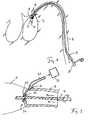
- Fig. 1shows a typical application of the shaft assembly according to the invention in the medical field in connection with a heart pump.
- a catheter 1is provided which is pushed through a blood vessel into a heart chamber 3 and which has a micropump 4 at its distal end.
- Thishas a housing 5, in which a rotor 6 by means of a shaft 7 is mechanically driven in rotation.
- the shaft 7is sealingly performed by a passage of the pump housing 5 in the catheter 1 and passed through the catheter 1 to a wave drive lying outside the body in the form of a motor 8.
- the pump housing 5 and the rotor 6 in such a cardiac catheter pumpare designed such that they are compressible for insertion through the blood vessel into the heart chamber and expandable within the heart chamber. To remove the pump from the body it is in turn compressed to be withdrawn through the vessel by means of the catheter can.
- the illustrated catheteris very flexible in order to be passed through without injury to the blood vessel by its bends, in particular the aortic arch. Accordingly, the shaft 7, which runs within the catheter acting as a sheath 1, must be flexible. This is usually achieved in that the shaft either consists of a very flexible material and is constructed in one piece, for example as a glass or plastic fiber, or that it is composed of different strands of lesser thickness by stranding or twisting.
- a corresponding surface structuremay be provided during the production, which causes a conveyance of a fluid in the longitudinal direction, at least at high rotational speeds of the shaft.
- a structureresults anyway and can be used for fluid delivery.
- Such a guidemay, for example, in a coil 9, consist, whose inner diameter is greater than that of the shaft and attached in the catheter or loosely wrapped around the shaft. It is as flexible as the catheter and provides a defined contact and friction surface for the shaft.
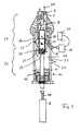
- Fig. 2shows in greatly enlarged scale the drive end of the shaft 7, which runs in the coil 9 within the sheath / catheter 1.
- a motor 8having a motor shaft 10 which may be identical to or directly coupled to the shaft 7.
- one of the shafts 7, 10can be performed through a bushing 11 with a bearing 12 and a stuffing box 13 in the connection space 28.
- Such an implementationcan be made as tight as possible, but not completely sealed.
- a feed pump 14which conveys the fluid from a reservoir 15, which surrounds the shaft 7 within the catheter 1 and conveys it through an inflow 16 into the connection space 28. From here, as shown by the arrows 17, 18, the fluid is conveyed along the shaft 7 in the flow direction 30 to the distal end of the catheter 1, provided that the shaft 7 is in rapid rotation and accordingly conveys the fluid with the spiral outer contour ,
- a sleeve 19which has conveying elements 20 on its circumference, which in the case shown are formed as spirally arranged conveying blades.
- the sleeve 19is rotatably mounted in a bearing 21 radially outward relative to the terminal housing 22. It is connected inwardly with the shaft 7, for example via struts or via a potting.
- the fluid pressureis slightly increased, while it is slightly lowered by suction on both sides in the region of the curly bracket 27. There, however, no undesirable fluid or gas can be sucked in, so that overall the formation of bubbles or the penetration of foreign fluids into the catheter 1 is prevented by the features of the invention.
- the pumping capacity of the sleeve 19is to be controlled by the design of the conveying elements 20 so that a balance pumping capacity of the shaft remains in operation, which ensures a moderate flow of fluid along the shaft 7 for cooling and lubrication purposes.
- Fig. 3shows the distal or the drive end facing away from the shaft 7 with a passage 34 from the catheter into the pump housing 5.
- the passage 34provides a stuffing box 29 and a bearing 35, which may be formed as a sliding bearing.
- the fluidis sucked through a drain opening 31 by means of a suction pump 32 via a drain line 33. It can then be returned to the reservoir 15 or removed altogether.
Landscapes
- Health & Medical Sciences (AREA)
- Engineering & Computer Science (AREA)
- Heart & Thoracic Surgery (AREA)
- Mechanical Engineering (AREA)
- Biomedical Technology (AREA)
- Veterinary Medicine (AREA)
- Cardiology (AREA)
- Anesthesiology (AREA)
- Public Health (AREA)
- Hematology (AREA)
- Life Sciences & Earth Sciences (AREA)
- Animal Behavior & Ethology (AREA)
- General Health & Medical Sciences (AREA)
- General Engineering & Computer Science (AREA)
- Oral & Maxillofacial Surgery (AREA)
- Physics & Mathematics (AREA)
- Fluid Mechanics (AREA)
- Vascular Medicine (AREA)
- External Artificial Organs (AREA)
Abstract
Description
Translated fromGermanDie Erfindung liegt auf dem Gebiet der Mechanik bzw. des Maschinenbaus und ist mit besonderem Vorteil in der Feinwerktechnik, das heißt beim Bau kleiner Maschinen und Geräte, einsetzbar.The invention is in the field of mechanics or mechanical engineering and is particularly advantageous in precision engineering, that is, in the construction of small machines and equipment used.
Besondere Vorteile bringt der Einsatz in der Medizintechnik, wo häufig, insbesondere bei der minimalinvasiven Medizin, Bewegungen über Wellen, insbesondere biegsame Wellen, durch kleine Öffnungen bzw. körpereigene Gefäße unter besonders schwierigen Umgebungsbedingungen übertragen werden müssen.Particular advantages are the use in medical technology, where often, especially in minimally invasive medicine, movements over waves, in particular flexible waves, must be transmitted through small openings or endogenous vessels under particularly difficult environmental conditions.
Eine besondere Anwendungsform stellt der Antrieb von Flüssigkeitspumpen in Mikrobauform dar, die beispielsweise als Herzpumpen Anwendung finden und die mit einem Herzkatheter an ihren Betriebsort, beispielsweise eine Herzkammer, gebracht werden können. Dazu müssen nicht nur die entsprechenden Pumpen sehr geringe Baugröße aufweisen, sondern auch für die Übertragung der Pumpleistung über eine Welle liegen schwierige Bedingungen vor. Die Welle verläuft üblicherweise durch einen Herzkatheter und wird vom Körperäußeren her durch eine Durchführung angetrieben. Am distalen Ende des Katheters wird die Bewegung auf die Pumpe übertragen. Derartige Wellen sind üblicherweise biegsam, so dass besonders bei den hohen benötigten Drehzahlen intensive Verformungen stattfinden. Daher stellt es nicht nur besonders hohe Anforderungen, die hohen Drehzahlen zu erreichen, sondern ebenso, die entsprechende Wärme, die durch die Verformung der Welle entsteht, abzuführen.A special application is the drive of liquid pumps in micro design, which are used, for example, as cardiac pumps and can be brought with a cardiac catheter to its operating location, such as a heart chamber. For this not only the corresponding pumps must have very small size, but also for the transmission of pump power through a wave are difficult conditions. The shaft usually passes through a cardiac catheter and is driven from the outside through a passage. At the distal end of the catheter, the movement is transferred to the pump. Such waves are usually flexible, so that take place especially at the high speeds required intense deformation. Therefore, it is not only very high demands to achieve the high speeds, but also to dissipate the corresponding heat generated by the deformation of the shaft.
Ein entsprechender Herzkatheter ist üblicherweise mit einer körperverträglichen Flüssigkeit gefüllt, um einerseits die Welle zu schmieren und andererseits zu kühlen.A corresponding cardiac catheter is usually filled with a biocompatible fluid, on the one hand to lubricate the shaft and on the other hand to cool.
Da entsprechende Wellen üblicherweise, um ihre Biegsamkeit zu fördern, aus dünneren Strängen zusammengesetzt und verdrillt sind, ergibt sich eine spindelförmige Oberflächenstruktur, die bei schneller Drehung zur Förderung des in dem Katheter befindlichen Fluids längs der Welle führt. Dieser Effekt ist im Allgemeinen unerwünscht, da er ein Druckgefälle des Fluids in dem Katheter schafft. Von dem antriebsseitigen Ende des Katheters her muss neues Fluid nachströmen. Ist dieses nicht verfügbar, so können entweder durch die Wellendurchführung oder auch durch eine Entlüftungsöffnung, die ebenfalls im antriebsnahen Bereich des Katheters vorgesehen sein kann und die zum Entlüften des Katheters dient, unerwünschte Flüssigkeiten oder Gase, beispielsweise Luft, angesaugt werden.Since such shafts are usually composed of thinner strands and twisted to promote their flexibility, a spindle-shaped surface structure results, which, with rapid rotation, leads to the conveyance of the fluid in the catheter along the shaft. This effect is generally undesirable because it creates a pressure gradient of the fluid in the catheter. New fluid must flow in from the drive end of the catheter. If this is not available, unwanted liquids or gases, for example air, can be sucked in either through the shaft passage or through a vent opening, which can likewise be provided in the area close to the drive of the catheter and which serves to vent the catheter.
Üblicherweise ist eine Zuführung für das in dem Katheter befindliche Fluid vorgesehen, durch die das Fluid mittels einer Pumpvorrichtung nachgepumpt wird. Es hat dabei Vorteile, eine nicht zu große Menge des Fluids zu pumpen, d. h. einen sehr geringen Volumenstrom zu erzeugen. Liefert jedoch die Pumpe der Fluidzuführung keinen ausreichenden Volumenstrom, so entsteht im Bereich des Fluidzuflusses durch die Absaugtendenz der Welle ein Unterdruck, der unerwünscht ist.Typically, a supply is provided for the fluid in the catheter, through which the fluid is pumped by means of a pumping device. It has advantages to pump a not too large amount of the fluid, d. H. to generate a very low volume flow. If, however, the pump of the fluid supply does not supply a sufficient volume flow, a negative pressure arises in the region of the fluid inflow through the suction tendency of the shaft, which is undesirable.
Der vorliegenden Erfindung liegt daher die Aufgabe zugrunde, bei einer Wellenanordnung der eingangs genannten Art eine bestimmungsgemäße blasenfreie Füllung der Wellenanordnung mit dem vorgesehenen Fluid zu ermöglichen.The present invention is therefore based on the object at a shaft assembly of the type mentioned a proper bubble-free filling of the shaft assembly with the intended fluid to allow.
Die Aufgabe wird gemäß der Erfindung mit den Merkmalen des Patentanspruchs 1 gelöst.The object is achieved according to the invention with the features of claim 1.
Es ist eine die Welle umgebende, beispielsweise im antriebsseitigen Endbereich der Welle angeordnete, mit dieser rotierende Hülse, eine sogenannte Gegenstromhülse, vorgesehen, die wenigstens ein Förderelement zur Förderung des Fluids in einer der Stromrichtung entgegengesetzten Gegenstromrichtung aufweist.It is a shaft surrounding, for example, in the drive-side end portion of the shaft disposed with this rotating sleeve, a so-called countercurrent sleeve, provided, which has at least one conveying element for conveying the fluid in a counterflow direction opposite to the current direction.
Beispielsweise kann die Hülse fest mit der Welle verbunden sein und entsprechend mit gleicher Drehzahl wie diese rotieren. Die Hülse kann auf ihrer Außenseite eine wendelartige Schaufelblattstruktur oder einzelne Schaufelblätter oder Stege in entsprechender schräg gestellter oder wendelförmiger Aufbaustruktur aufweisen. Wichtig dabei ist, dass die Hülse eine Strömung bzw. einen Druckanstieg entgegen der Stromrichtung, d.h. in Richtung des Wellenendes bzw. zum Anschlussraum hin erzeugt. Dadurch wird ein Unterdruck im Anschlussraum und das Einströmen von Luft durch eine Entlüftungsöffnung oder die Wellendurchführung wirksam verhindert. Auch ein übermäßiges Nachsaugen des Fluids, falls dies durch einen Fluidzufluss nachgeliefert wird, wird vermieden. Durch die Hülse wird zum antriebsseitigen Wellenende hin der Druck erhöht, während er auf der antriebsfernen Seite der Hülse durch das Ansaugen etwas abgesenkt wird. In diesem Bereich wirken die Förderrichtungen der Welle einerseits und der Hülse andererseits gegeneinander, so dass dort tendenziell der Druck abgesenkt wird. In diesem Bereich befindet sich jedoch kein Zufluss und keine Öffnung, so dass dort die Entstehung von Gasblasen vermieden werden kann.For example, the sleeve may be firmly connected to the shaft and correspondingly rotate at the same speed as this. The sleeve may have on its outside a helical airfoil structure or individual airfoils or webs in a corresponding inclined or helical structure structure. It is important that the sleeve has a flow or an increase in pressure against the direction of flow, ie generated in the direction of the shaft end or to the terminal compartment. As a result, a negative pressure in the connection space and the inflow of air through a vent or the shaft passage is effectively prevented. An excessive suction of the fluid, if this is replenished by a fluid flow, is avoided. Through the sleeve, the pressure is increased to the drive end shaft end, while it is slightly lowered on the drive remote side of the sleeve by the suction. In this area, the conveying directions of the shaft on the one hand and the sleeve on the other hand act against each other, so that there tends to be the pressure is lowered. In this area, however, there is no inflow and no opening, so that there the formation of gas bubbles can be avoided.
Damit bewirkt die Erfindung, dass die Welle zuverlässig mit hohen Drehzahlen betrieben werden kann, ohne dass die Fluidkühlung und/oder -schmierung aussetzt und ohne dass Gasblasen entlang der Welle zum antriebsfernen Ende eines Katheters gefördert werden.Thus, the invention causes the shaft can be reliably operated at high speeds without exposing the fluid cooling and / or lubrication and without gas bubbles are conveyed along the shaft to the drive remote end of a catheter.
Auch bei anderen Einsätzen im nichtmedizinischen Bereich ist eine derartige Blasenbildung in einem die Welle umgebenden Fluid unerwünscht und kann mit den Mitteln der Erfindung verhindert werden.Even in other non-medical applications, such blistering in a fluid surrounding the shaft is undesirable and can be prevented by the means of the invention.
Eine vorteilhafte Ausgestaltung der Erfindung sieht vor, dass die Hülse in Stromrichtung gesehen hinter einem Anschlussraum angeordnet ist, in den eine Durchführung der Welle oder eines Wellenantriebs mündet.An advantageous embodiment of the invention provides that the sleeve is arranged in the flow direction behind a connection space, in which a passage of the shaft or a shaft drive opens.
In dem Anschlussraum, der üblicherweise im antriebsseitigen Endbereich der Welle angeordnet ist, kann auch zusätzlich oder alternativ zu einer Wellendurchführung eine Fluidzuführung für das die Hülle füllende Fluid und/oder eine Entlüftungsöffnung zur Entlüftung des eingefüllten Fluids angeordnet sein.In the connection space, which is usually arranged in the drive-side end portion of the shaft can Also, in addition to or alternatively to a shaft passage, a fluid supply for the fluid filling the sheath and / or a vent for venting the filled fluid may be arranged.
Vorteilhaft ist in jedem Fall, dass mittels der Hülse im Betrieb ein Druckabfall im Anschlussraum verhindert wird, um dort das Eindringen von Gasblasen oder anderen unerwünschten Fluiden oder das übermäßige Nachsaugen des Fluids, mit dem die Hülle gefüllt ist, zu verhindern. Durch die Anordnung der Hülse hinter dem Anschlussraum in Stromrichtung gesehen wirken dort, d. h. in einem Bereich, der vom antriebsseitigen Ende und dem Anschlußraum der Welle üblicherweise ein Stück beabstandet ist, die Pumpwirkungen der Hülse und der Welle gegeneinander, so dass in diesem Bereich, außerhalb des Anschlussraums, der Druck des Fluids abgesenkt wird, wo üblicherweise keine Öffnungen in der Hülle vorgesehen sind und somit keine unerwünschten Stoffe angesaugt werden können.It is advantageous in any case that by means of the sleeve during operation, a pressure drop in the connection space is prevented in order to prevent the penetration of gas bubbles or other undesirable fluids or the excessive suction of the fluid with which the shell is filled. Seen through the arrangement of the sleeve behind the terminal compartment in the direction of flow act there, d. H. in a region which is usually a piece from the drive end and the connection space of the shaft, the pumping effects of the sleeve and the shaft against each other, so that in this area, outside the terminal space, the pressure of the fluid is lowered, where usually no openings in the shell are provided and thus no unwanted substances can be sucked.
Um eine angemessene Führung der Hülse bei der Rotationsbewegung zu gewährleisten und je nach der Art der Kopplung zwischen der Hülse und der Welle auch unerwünschte Interaktionen zwischen diesen zu verhindern, kann vorteilhaft eine Lagerung der Hülse an ihrem äußeren Umfang, insbesondere mittels eines Wälzlagers, vorgesehen sein. Es kann dort jedoch wahlweise auch ein Magnetlager oder ein gut geschmiertes Gleitlager vorgesehen sein.In order to ensure an adequate guidance of the sleeve during the rotational movement and, depending on the type of coupling between the sleeve and the shaft, also to prevent undesired interactions therebetween, advantageously a bearing of the sleeve can be provided on its outer circumference, in particular by means of a roller bearing , However, there may alternatively be provided a magnetic bearing or a well-lubricated plain bearing there.
Je nach Art des Lagers kann auch ein weiteres Lager zur Stützung der Hülse vorteilhaft vorgesehen sein.Depending on the nature of the bearing, another bearing may be advantageously provided for supporting the sleeve.
Die Welle weist vorteilhaft zur Erzielung der Pumpwirkung in ihrer Längsrichtung an ihrer Oberfläche eine spindelförmige Außenkontur auf. Diese bewirkt bei einer Rotation, insbesondere bei Drehzahlen zwischen 20.000 und 40.000 Umdrehungen pro Minute, eine Förderung des Fluids in Längsrichtung zusätzlich zu etwa noch auftretenden radialen und azimutalen Bewegungsrichtungen des Fluids. Diese Pumpwirkung der Welle reicht aus, um eine kontinuierliche Kühlung und Schmierung zu gewährleisten. Die Welle kann beispielsweise aus einem Bündel von verdrillten Strängen, z. B. Drähten oder Fasern, insbesondere Glasfasern, bestehen und bereits hierdurch die spindelförmige Außenkontur aufweisen. Die Verdrillung der einzelnen Stränge ist üblicherweise derart gerichtet, dass sie mit der natürlichen Verdrillung durch Aufbringen eines Drehmoments am antriebsseitigen Ende übereinstimmt, so dass im Betrieb die Verdrillung der Welle stabilisiert wird. Dieser Verdrillungssinn stimmt mit der für die Pumprichtung zum antriebsfernen Ende notwendigen spindelförmigen Kontur überein.The shaft advantageously has to achieve the pumping action in its longitudinal direction on its surface a spindle-shaped outer contour. This causes a rotation, in particular at speeds between 20,000 and 40,000 revolutions per minute, a promotion of the fluid in the longitudinal direction in addition to any still occurring radial and azimuthal directions of movement of the fluid. This pumping action of the shaft is sufficient to ensure continuous cooling and lubrication. The shaft may, for example, consist of a bundle of twisted strands, e.g. As wires or fibers, in particular glass fibers, and already thereby have the spindle-shaped outer contour. The twist of the individual strands is usually directed to coincide with the natural twist by applying a torque at the drive end, so that in operation the twist of the shaft is stabilized. This twisting sense coincides with the spindle-shaped contour necessary for the pumping direction to the drive-far end.
Vorteilhaft kann die Hülle der Welle an ihrem dem Antrieb fernen Ende einen Auslass für das Fluid aufweisen. In diesem Fall kann dort das Fluid entweder ausgelassen werden, beispielsweise auch durch eine Durchführung der Welle, z. B. wenn diese in ein nachfolgend angeordnetes Pumpengehäuse weiterführt, oder das Fluid kann an dem Auslass abgepumpt und zurückgeführt werden.Advantageously, the shell of the shaft may have an outlet for the fluid at its end remote from the drive. In this case, there, the fluid can either be omitted, for example by a passage of the shaft, z. B. if this continues into a subsequently arranged pump housing, or the fluid can be pumped out at the outlet and returned.
In jedem Fall wird das Fluid im Falle einer Verwendung im medizinischen Bereich ein körperverträgliches Fluid wie beispielsweise eine Kochsalzlösung sein, so dass eventuell ins Körpergewebe oder in ein Blutgefäß eintretende Flüssigkeitsmengen keinen schädlichen Einfluss haben.In any event, if used in the medical field, the fluid will be a biocompatible fluid, such as saline, so that any quantities of fluid entering the body tissue or into a blood vessel will not be detrimental.
An dem entsprechenden Auslass kann das Fluid auch aktiv abgesaugt werden, um einen unbeabsichtigten Austritt durch Öffnungen, wie beispielsweise eine Wellendurchführung, zu verhindern.At the corresponding outlet, the fluid can also be actively aspirated to prevent inadvertent escape through openings, such as a shaft passage.
Die Erfindung bezieht sich außer auf eine Wellenanordnung der beschriebenen Art auch auf ein Verfahren zum Betrieb einer derartigen Wellenanordnung, bei dem die Welle mit einer Geschwindigkeit von mindestens 300 Umdrehungen pro Minute rotiert. Das vorteilhafte Verfahren kann außerdem vorsehen, dass die Welle mit einer Geschwindigkeit von nicht mehr als 40.000 Umdrehungen pro Minute rotiert.The invention relates, in addition to a shaft assembly of the type described, to a method of operating such a shaft assembly in which the shaft rotates at a speed of at least 300 revolutions per minute. The advantageous method may also provide that the shaft rotates at a speed of not more than 40,000 revolutions per minute.
Zudem kann vorgesehen sein, dass zur Kühlung und Schmierung der Welle ein konstanter Fluss des die Hülle füllenden Fluids in den Anschlussraum gepumpt wird. Dabei kann je nach Einrichtung der Speisepumpe ein konstanter Volumenstrom eingepumpt werden, oder es kann in dem Anschlussraum ein konstanter Druck des Fluids aufrechterhalten werden. Üblicherweise werden sich beim Betrieb der Welle nach kurzer Zeit stabile Betriebsparameter einstellen.In addition, it can be provided that, for cooling and lubricating the shaft, a constant flow of the fluid filling the casing is pumped into the connection space. Depending on the device of the feed pump, a constant volume flow can be pumped in, or a constant pressure of the fluid can be maintained in the connection space. Usually, stable operating parameters will occur after a short time when the shaft is operating.
Das erfindungsgemäße Verfahren kann außerdem vorsehen, dass das Fluid an einem Auslass an dem antriebsfernen Ende aus der Hülle der Welle abgesaugt wird.The inventive method can also provide that the fluid is sucked out of the shell of the shaft at an outlet at the end remote from the drive.
Im Folgenden wird die Erfindung anhand eines Ausführungsbeispiels in einer Zeichnung gezeigt und anschließend beschrieben.In the following the invention will be shown by means of an embodiment in a drawing and described below.
Dabei zeigt
- Fig. 1
- eine schematische Übersicht über einen Ka- theter mit einer Welle, die zu einer in ei- ne Herzkammer eingebrachten Pumpe führt,
- Fig. 2
- schematisch einen Längsschnitt durch den antriebsseitigen Endbereich eines Katheters mit einer eingezogenen Antriebswelle und
- Fig. 3
- eine Ansicht eines distalen Endes eines Ka- theters mit einer Welle.
- Fig. 1
- a schematic overview of a catheter with a shaft leading to a pump inserted in a ventricle,
- Fig. 2
- schematically a longitudinal section through the drive-side end portion of a catheter with a retracted drive shaft and
- Fig. 3
- a view of a distal end of a catheter with a shaft.
Die Welle 7 ist durch eine Durchführung des Pumpengehäuses 5 in den Katheter 1 dichtend durchgeführt und durch den Katheter 1 bis zu einem außerhalb des Körpers liegenden Wellenantrieb in Form eines Motors 8 geführt.The
Üblicherweise sind das Pumpengehäuse 5 und der Rotor 6 bei einer solchen Herzkatheterpumpe derart ausgebildet, dass sie zum Einführen durch das Blutgefäß in die Herzkammer komprimierbar und innerhalb der Herzkammer expandierbar sind. Zum Entfernen der Pumpe aus dem Körper wird diese wiederum komprimiert, um durch das Gefäß mittels des Katheters zurückgezogen werden zu können.Usually, the
Der dargestellte Katheter ist sehr biegsam, um ohne Verletzung des Blutgefäßes durch dessen Biegungen, insbesondere den Aortenbogen, hindurchführbar zu sein. Entsprechend muss auch die Welle 7, die innerhalb des als Hülle 1 wirkenden Katheters verläuft, biegsam sein. Dies wird üblicherweise dadurch erreicht, dass die Welle entweder aus einem sehr biegsamen Material besteht und einstückig aufgebaut ist, beispielsweise als Glas- oder Kunststofffaser, oder dass sie aus verschiedenen Strängen geringerer Dicke durch Verseilung oder Verdrillung aufgebaut ist.The illustrated catheter is very flexible in order to be passed through without injury to the blood vessel by its bends, in particular the aortic arch. Accordingly, the
Im Falle einer einstückigen Herstellung kann bei der Herstellung eine entsprechende Oberflächenstruktur vorgesehen werden, die zumindest bei hohen Drehzahlen der Welle eine Förderung eines Fluids in Längsrichtung bewirkt. Bei der Herstellung durch Verdrillung ergibt sich eine derartige Struktur ohnehin und kann für die Fluidförderung genutzt werden.In the case of a one-piece production, a corresponding surface structure may be provided during the production, which causes a conveyance of a fluid in the longitudinal direction, at least at high rotational speeds of the shaft. In the production by twisting, such a structure results anyway and can be used for fluid delivery.
In jedem Fall ergibt sich bei hohen Drehzahlen der Welle, also insbesondere zwischen 20.000 und 40.000 Umdrehungen pro Minute, eine hohe Verformungsgeschwindigkeit der Welle und gegebenenfalls auch Reibung zwischen den einzelnen Elementen, die zur Erwärmung der Welle führt. Aus diesem Grunde ist die Einbettung der Welle in eine Flüssigkeit sinnvoll, die einerseits Wärme abführt und andererseits für einen Schmierfilm zwischen verschiedenen Elementen der Welle 7 oder auch zwischen der Welle und einer diese umgebenden Führung, beispielsweise einer flexiblen Drahtwendel, sorgt.In any case, results in high rotational speeds of the shaft, ie in particular between 20,000 and 40,000 revolutions per minute, a high deformation rate of the shaft and possibly also friction between the individual elements, which leads to heating of the shaft. For this reason, the embedding of the wave in a liquid makes sense, on the one hand dissipates heat and on the other hand for a lubricating film between different elements of the
Eine derartige Führung kann beispielsweise in einer Wendel 9, bestehen, deren Innendurchmesser größer als der der Welle ist und die in dem Katheter befestigt oder lose um die Welle herumgelegt ist. Sie ist ebenso biegbar wie der Katheter und stellt eine definierte Kontakt- und Reibungsfläche für die Welle her.Such a guide may, for example, in a
Es ist ein Motor 8 dargestellt, der eine Motorwelle 10 aufweist, die unmittelbar mit der Welle 7 identisch oder an diese angekoppelt sein kann. Zu diesem Zweck kann eine der Wellen 7, 10 durch eine Durchführung 11 mit einem Lager 12 und einer Stopfbuchse 13 in den Anschlussraum 28 durchgeführt sein. Eine derartige Durchführung kann weitestgehend dicht, jedoch nicht vollkommen dicht ausgeführt sein.There is shown a
Des Weiteren zeigt die
Es ist zudem eine Hülse 19 dargestellt, die Förderelemente 20 an ihrem Umfang aufweist, die im dargestellten Fall als spiralig angeordnete Förderschaufeln ausgeprägt sind.In addition, a
Die Hülse 19 ist in einem Lager 21 radial außen gegenüber dem Anschlussraumgehäuse 22 drehbar gelagert. Sie ist nach innen mit der Welle 7 verbunden, beispielsweise über Streben oder über einen Verguss.The
Durch Rotation der Hülse 19 und die Funktion der Förderelemente 20 wird eine Strömung des Fluids in Richtung der Pfeile 23, 24 erreicht, und zwar in den Anschlussraum 28 hinein. Dadurch wird im Anschlussraum 28 der Druck des Fluids leicht erhöht. Es wird hierdurch sichergestellt, dass das Ansaugen von Fremdflüssigkeiten oder Gas bzw. Luft sowohl durch die Durchführung 11 als auch durch eine Belüftungsöffnung 25 oder den Zufluss 16 verhindert wird.By rotation of the
Durch die kombinierte Wirkung der Hülse 19 und der fördernden Welle 7 wird in dem mit der geschweiften Klammer 26 bezeichneten Bereich der Fluiddruck leicht erhöht, während er durch beidseitiges Absaugen in dem Bereich der geschweiften Klammer 27 leicht gesenkt wird. Dort kann jedoch kein unerwünschtes Fluid oder Gas angesaugt werden, so dass insgesamt die Bildung von Blasen oder das Eindringen von Fremdfluiden in den Katheter 1 durch die Merkmale der Erfindung verhindert wird. Die Pumpleistung der Hülse 19 ist durch die Gestaltung der Förderelemente 20 derart zu steuern, dass eine Saldopumpleistung der Welle im Betrieb bestehen bleibt, die einen mäßigen Fluss des Fluids entlang der Welle 7 zu Kühlungs- und Schmierungszwecken gewährleistet.By the combined action of the
Um einen Fluidfluss zu gewährleisten und das Austreten des Fluids durch die Durchführung 34 zu verhindern oder zu verringern, wird das Fluid durch eine Abflussöffnung 31 mittels einer Absaugpumpe 32 über eine Abflussleitung 33 abgesaugt. Es kann dann wieder dem Reservoir 15 zugeführt oder gänzlich entfernt werden.In order to ensure a fluid flow and to prevent or reduce the leakage of the fluid through the
Obwohl die Erfindung in einer speziellen Anwendung im medizintechnischen Bereich beschrieben wurde, ist sie universell einsetzbar, insbesondere bei verschiedensten Anwendungen biegsamer Wellen, z. B. bei Werkzeugen zur spanenden Bearbeitung von Bauteilen, wo eine Kühlung und Schmierung der Welle durch ein Fluid wichtig sein kann.Although the invention has been described in a particular application in the medical field, it is universally applicable, especially in a variety of applications flexible shafts, z. As in tools for machining components where cooling and lubrication of the shaft by a fluid may be important.
Claims (16)
Translated fromGermanPriority Applications (4)
| Application Number | Priority Date | Filing Date | Title |
|---|---|---|---|
| EP09075211AEP2246078A1 (en) | 2009-04-29 | 2009-04-29 | Shaft assembly with a shaft which moves within a fluid-filled casing |
| PCT/EP2010/002829WO2010124882A1 (en) | 2009-04-29 | 2010-04-29 | Shaft arrangement having a shaft which extends within a fluid-filled casing |
| US13/266,212US8900060B2 (en) | 2009-04-29 | 2010-04-29 | Shaft arrangement having a shaft which extends within a fluid-filled casing |
| EP10721116.1AEP2424587B1 (en) | 2009-04-29 | 2010-04-29 | Shaft arrangement having a shaft which extends within a fluid-filled casing |
Applications Claiming Priority (1)
| Application Number | Priority Date | Filing Date | Title |
|---|---|---|---|
| EP09075211AEP2246078A1 (en) | 2009-04-29 | 2009-04-29 | Shaft assembly with a shaft which moves within a fluid-filled casing |
Publications (1)
| Publication Number | Publication Date |
|---|---|
| EP2246078A1true EP2246078A1 (en) | 2010-11-03 |
Family
ID=41217745
Family Applications (2)
| Application Number | Title | Priority Date | Filing Date |
|---|---|---|---|
| EP09075211AWithdrawnEP2246078A1 (en) | 2009-04-29 | 2009-04-29 | Shaft assembly with a shaft which moves within a fluid-filled casing |
| EP10721116.1AActiveEP2424587B1 (en) | 2009-04-29 | 2010-04-29 | Shaft arrangement having a shaft which extends within a fluid-filled casing |
Family Applications After (1)
| Application Number | Title | Priority Date | Filing Date |
|---|---|---|---|
| EP10721116.1AActiveEP2424587B1 (en) | 2009-04-29 | 2010-04-29 | Shaft arrangement having a shaft which extends within a fluid-filled casing |
Country Status (3)
| Country | Link |
|---|---|
| US (1) | US8900060B2 (en) |
| EP (2) | EP2246078A1 (en) |
| WO (1) | WO2010124882A1 (en) |
Cited By (15)
| Publication number | Priority date | Publication date | Assignee | Title |
|---|---|---|---|---|
| WO2016116630A3 (en)* | 2015-01-22 | 2016-10-27 | Ecp Entwicklungsgesellschaft Mbh | Catheter device comprising a separating device for retaining magnetic particles contained in a fluid and protection device for a functional element |
| WO2018146177A1 (en)* | 2017-02-13 | 2018-08-16 | Cardiobridge Gmbh | Catheter pump comprising drive unit and catheter |
| US10722631B2 (en) | 2018-02-01 | 2020-07-28 | Shifamed Holdings, Llc | Intravascular blood pumps and methods of use and manufacture |
| US10882505B1 (en)* | 2019-09-04 | 2021-01-05 | Chih-Yang Yen | Brake cable with lubricant sealing device |
| US11185677B2 (en) | 2017-06-07 | 2021-11-30 | Shifamed Holdings, Llc | Intravascular fluid movement devices, systems, and methods of use |
| US11511103B2 (en) | 2017-11-13 | 2022-11-29 | Shifamed Holdings, Llc | Intravascular fluid movement devices, systems, and methods of use |
| US20230052997A1 (en)* | 2020-01-31 | 2023-02-16 | Ecp Entwicklungsgesellschaft Mbh | Intravascular blood pump |
| US11654275B2 (en) | 2019-07-22 | 2023-05-23 | Shifamed Holdings, Llc | Intravascular blood pumps with struts and methods of use and manufacture |
| US11724089B2 (en) | 2019-09-25 | 2023-08-15 | Shifamed Holdings, Llc | Intravascular blood pump systems and methods of use and control thereof |
| US11964145B2 (en) | 2019-07-12 | 2024-04-23 | Shifamed Holdings, Llc | Intravascular blood pumps and methods of manufacture and use |
| US12102815B2 (en) | 2019-09-25 | 2024-10-01 | Shifamed Holdings, Llc | Catheter blood pumps and collapsible pump housings |
| US12121713B2 (en) | 2019-09-25 | 2024-10-22 | Shifamed Holdings, Llc | Catheter blood pumps and collapsible blood conduits |
| US12161857B2 (en) | 2018-07-31 | 2024-12-10 | Shifamed Holdings, Llc | Intravascular blood pumps and methods of use |
| US12220570B2 (en) | 2018-10-05 | 2025-02-11 | Shifamed Holdings, Llc | Intravascular blood pumps and methods of use |
| US12409310B2 (en) | 2019-12-11 | 2025-09-09 | Shifamed Holdings, Llc | Descending aorta and vena cava blood pumps |
Families Citing this family (61)
| Publication number | Priority date | Publication date | Assignee | Title |
|---|---|---|---|---|
| EP2194278A1 (en) | 2008-12-05 | 2010-06-09 | ECP Entwicklungsgesellschaft mbH | Fluid pump with a rotor |
| EP2216059A1 (en) | 2009-02-04 | 2010-08-11 | ECP Entwicklungsgesellschaft mbH | Catheter device with a catheter and an actuation device |
| EP2229965A1 (en) | 2009-03-18 | 2010-09-22 | ECP Entwicklungsgesellschaft mbH | Fluid pump with particular form of a rotor blade |
| EP2246078A1 (en) | 2009-04-29 | 2010-11-03 | ECP Entwicklungsgesellschaft mbH | Shaft assembly with a shaft which moves within a fluid-filled casing |
| EP2248544A1 (en) | 2009-05-05 | 2010-11-10 | ECP Entwicklungsgesellschaft mbH | Fluid pump with variable circumference, particularly for medical use |
| EP2266640A1 (en) | 2009-06-25 | 2010-12-29 | ECP Entwicklungsgesellschaft mbH | Compressible and expandable turbine blade for a fluid pump |
| EP2282070B1 (en) | 2009-08-06 | 2012-10-17 | ECP Entwicklungsgesellschaft mbH | Catheter device with a coupling device for a drive device |
| EP2298371A1 (en) | 2009-09-22 | 2011-03-23 | ECP Entwicklungsgesellschaft mbH | Function element, in particular fluid pump with a housing and a transport element |
| EP2298373A1 (en) | 2009-09-22 | 2011-03-23 | ECP Entwicklungsgesellschaft mbH | Fluid pump with at least one turbine blade and a seating device |
| EP2299119B1 (en) | 2009-09-22 | 2018-11-07 | ECP Entwicklungsgesellschaft mbH | Inflatable rotor for a fluid pump |
| EP2298372A1 (en) | 2009-09-22 | 2011-03-23 | ECP Entwicklungsgesellschaft mbH | Rotor for an axial pump for transporting a fluid |
| EP2314331B1 (en) | 2009-10-23 | 2013-12-11 | ECP Entwicklungsgesellschaft mbH | Catheter pump arrangement and flexible shaft arrangement with a cable core |
| EP2314330A1 (en) | 2009-10-23 | 2011-04-27 | ECP Entwicklungsgesellschaft mbH | Flexible shaft arrangement |
| EP2338541A1 (en) | 2009-12-23 | 2011-06-29 | ECP Entwicklungsgesellschaft mbH | Radial compressible and expandable rotor for a fluid pump |
| EP2338539A1 (en) | 2009-12-23 | 2011-06-29 | ECP Entwicklungsgesellschaft mbH | Pump device with a detection device |
| EP2338540A1 (en) | 2009-12-23 | 2011-06-29 | ECP Entwicklungsgesellschaft mbH | Delivery blade for a compressible rotor |
| EP2347778A1 (en) | 2010-01-25 | 2011-07-27 | ECP Entwicklungsgesellschaft mbH | Fluid pump with a radially compressible rotor |
| EP2363157A1 (en) | 2010-03-05 | 2011-09-07 | ECP Entwicklungsgesellschaft mbH | Device for exerting mechanical force on a medium, in particular fluid pump |
| EP2388029A1 (en) | 2010-05-17 | 2011-11-23 | ECP Entwicklungsgesellschaft mbH | Pump array |
| EP2399639A1 (en) | 2010-06-25 | 2011-12-28 | ECP Entwicklungsgesellschaft mbH | System for introducing a pump |
| EP2407185A1 (en) | 2010-07-15 | 2012-01-18 | ECP Entwicklungsgesellschaft mbH | Radial compressible and expandable rotor for a pump with a turbine blade |
| EP2407186A1 (en) | 2010-07-15 | 2012-01-18 | ECP Entwicklungsgesellschaft mbH | Rotor for a pump, produced with an initial elastic material |
| EP2407187A3 (en) | 2010-07-15 | 2012-06-20 | ECP Entwicklungsgesellschaft mbH | Blood pump for invasive application within the body of a patient |
| EP2422735A1 (en) | 2010-08-27 | 2012-02-29 | ECP Entwicklungsgesellschaft mbH | Implantable blood transportation device, manipulation device and coupling device |
| EP2497521A1 (en) | 2011-03-10 | 2012-09-12 | ECP Entwicklungsgesellschaft mbH | Push device for axial insertion of a string-shaped, flexible body |
| EP2564771A1 (en) | 2011-09-05 | 2013-03-06 | ECP Entwicklungsgesellschaft mbH | Medicinal product with a functional element for invasive use in the body of a patient |
| US8926492B2 (en) | 2011-10-11 | 2015-01-06 | Ecp Entwicklungsgesellschaft Mbh | Housing for a functional element |
| CN108742951B (en) | 2012-06-06 | 2021-05-25 | 洋红医疗有限公司 | Artificial kidney valve |
| US10583231B2 (en) | 2013-03-13 | 2020-03-10 | Magenta Medical Ltd. | Blood pump |
| EP4233702A3 (en) | 2013-03-13 | 2023-12-20 | Magenta Medical Ltd. | Manufacture of an impeller |
| WO2016185473A1 (en) | 2015-05-18 | 2016-11-24 | Magenta Medical Ltd. | Blood pump |
| CA3039285A1 (en) | 2016-10-25 | 2018-05-03 | Magenta Medical Ltd. | Ventricular assist device |
| JP7094279B2 (en) | 2016-11-23 | 2022-07-01 | マジェンタ・メディカル・リミテッド | Blood pump |
| JP7128818B2 (en)* | 2016-12-19 | 2022-08-31 | アビオメド インコーポレイテッド | Heart pump with passive purge system |
| US10926013B2 (en) | 2017-04-07 | 2021-02-23 | Ecp Entwicklungsgesellschaft Mbh | Methods and systems for an external drive unit for an implantable heart assist pump |
| IL309561B2 (en)* | 2017-04-07 | 2025-06-01 | Ecp Entw Mbh | External drive unit for implantable heart assist pump |
| ES2870150T3 (en)* | 2017-08-22 | 2021-10-26 | Ecp Entw Mbh | External drive unit for an implantable heart assist pump |
| EP3638336B1 (en) | 2018-01-10 | 2022-04-06 | Magenta Medical Ltd. | Ventricular assist device |
| US10905808B2 (en) | 2018-01-10 | 2021-02-02 | Magenta Medical Ltd. | Drive cable for use with a blood pump |
| DE102018201030B4 (en) | 2018-01-24 | 2025-10-16 | Kardion Gmbh | Magnetic dome element with magnetic bearing function |
| DE102018207611A1 (en) | 2018-05-16 | 2019-11-21 | Kardion Gmbh | Rotor bearing system |
| DE102018207575A1 (en) | 2018-05-16 | 2019-11-21 | Kardion Gmbh | Magnetic face turning coupling for the transmission of torques |
| DE102018208541A1 (en) | 2018-05-30 | 2019-12-05 | Kardion Gmbh | Axial pump for a cardiac assist system and method of making an axial pump for a cardiac assist system |
| DE102018208538A1 (en) | 2018-05-30 | 2019-12-05 | Kardion Gmbh | Intravascular blood pump and process for the production of electrical conductors |
| DE102018208550A1 (en) | 2018-05-30 | 2019-12-05 | Kardion Gmbh | A lead device for directing blood flow to a cardiac assist system, cardiac assist system, and method of making a lead device |
| DE102018208539A1 (en) | 2018-05-30 | 2019-12-05 | Kardion Gmbh | A motor housing module for sealing an engine compartment of a motor of a cardiac assist system and cardiac assistance system and method for mounting a cardiac assist system |
| DE102018210058A1 (en) | 2018-06-21 | 2019-12-24 | Kardion Gmbh | Stator blade device for guiding the flow of a fluid flowing out of an outlet opening of a heart support system, heart support system with stator blade device, method for operating a stator blade device and manufacturing method |
| DE102018210076A1 (en) | 2018-06-21 | 2019-12-24 | Kardion Gmbh | Method and device for detecting a state of wear of a cardiac support system, method and device for operating a cardiac support system and cardiac support system |
| DE102018211327A1 (en) | 2018-07-10 | 2020-01-16 | Kardion Gmbh | Impeller for an implantable vascular support system |
| DE102018212153A1 (en) | 2018-07-20 | 2020-01-23 | Kardion Gmbh | Inlet line for a pump unit of a cardiac support system, cardiac support system and method for producing an inlet line for a pump unit of a cardiac support system |
| CN112654389A (en) | 2018-08-07 | 2021-04-13 | 开迪恩有限公司 | Bearing device for a cardiac support system and method for flushing an intermediate space in a bearing device for a cardiac support system |
| EP3867541B1 (en) | 2018-10-18 | 2025-01-08 | Boston Scientific Scimed Inc. | Blood pump |
| AU2020211431B2 (en) | 2019-01-24 | 2024-10-24 | Magenta Medical Ltd | Ventricular assist device |
| JP7729779B2 (en) | 2019-03-26 | 2025-08-26 | パズル メディカル デバイシズ インコーポレイテッド | Modular mammalian body implantable fluid flow affecting device and related methods |
| EP3972661B1 (en) | 2019-05-23 | 2024-09-11 | Magenta Medical Ltd. | Blood pumps |
| US11666748B2 (en)* | 2019-08-30 | 2023-06-06 | Boston Scientific Scimed, Inc. | Hybrid bearing seal for use in blood pump |
| US12383723B2 (en) | 2019-10-05 | 2025-08-12 | Puzzle Medical Devices Inc. | Mammalian body implantable fluid flow influencing device |
| DE102020102474A1 (en) | 2020-01-31 | 2021-08-05 | Kardion Gmbh | Pump for conveying a fluid and method for manufacturing a pump |
| EP3984589B1 (en) | 2020-04-07 | 2023-08-23 | Magenta Medical Ltd. | Magnetic phase sensing |
| WO2023202165A1 (en)* | 2022-04-22 | 2023-10-26 | 上海微创心力医疗科技有限公司 | Blood pump and heart assist device |
| WO2024092349A1 (en) | 2022-11-01 | 2024-05-10 | Puzzle Medical Devices Inc. | Implantable medical devices and related methods thereof |
Citations (6)
| Publication number | Priority date | Publication date | Assignee | Title |
|---|---|---|---|---|
| FR1186539A (en)* | 1957-11-18 | 1959-08-26 | Flexible transmissions improvements | |
| DE7926329U1 (en)* | 1980-01-31 | 6700 Ludwigshafen | Device for the lubrication and cooling of flexible shafts | |
| US4280338A (en)* | 1979-11-29 | 1981-07-28 | General Motors Corporation | Rotatable flexible drive shaft with noise abatement |
| EP0347098A2 (en)* | 1988-06-13 | 1989-12-20 | Samuel Shiber | Atherectomy system with a guide-wire |
| WO2001017581A2 (en)* | 1999-09-03 | 2001-03-15 | A-Med Systems, Inc. | Guidable intravascular blood pump and related methods |
| EP2047872A1 (en)* | 2007-10-08 | 2009-04-15 | Ais Gmbh Aachen Innovative Solutions | Catheter device |
Family Cites Families (176)
| Publication number | Priority date | Publication date | Assignee | Title |
|---|---|---|---|---|
| US1545628A (en)* | 1924-03-27 | 1925-07-14 | Wolk Joseph | Automatic lubricator for universal joints |
| US2679061A (en)* | 1949-08-31 | 1954-05-25 | Elliott Co | Rotary tube cleaner |
| US3510229A (en) | 1968-07-23 | 1970-05-05 | Maytag Co | One-way pump |
| US3568659A (en) | 1968-09-24 | 1971-03-09 | James N Karnegis | Disposable percutaneous intracardiac pump and method of pumping blood |
| CH538410A (en) | 1971-02-17 | 1973-06-30 | L Somers S Brice | Flexible device for the transport of granular, powdery or fluid products |
| DE2113986A1 (en) | 1971-03-23 | 1972-09-28 | Svu Textilni | Artificial heart machine - with ptfe or similar inert plastic coated parts,as intracorperal replacement |
| US4014317A (en) | 1972-02-18 | 1977-03-29 | The United States Of America As Represented By The Department Of Health, Education And Welfare | Multipurpose cardiocirculatory assist cannula and methods of use thereof |
| US3812812A (en) | 1973-06-25 | 1974-05-28 | M Hurwitz | Trolling propeller with self adjusting hydrodynamic spoilers |
| US4020683A (en)* | 1976-06-21 | 1977-05-03 | Young Michael R | Fluid measuring valve and system to measure miles per gallon of a vehicle |
| US4207028A (en) | 1979-06-12 | 1980-06-10 | Ridder Sven O | Extendable and retractable propeller for watercraft |
| US4559951A (en) | 1982-11-29 | 1985-12-24 | Cardiac Pacemakers, Inc. | Catheter assembly |
| US4563181A (en) | 1983-02-18 | 1986-01-07 | Mallinckrodt, Inc. | Fused flexible tip catheter |
| US4686982A (en)* | 1985-06-19 | 1987-08-18 | John Nash | Spiral wire bearing for rotating wire drive catheter |
| US4679558A (en) | 1985-08-12 | 1987-07-14 | Intravascular Surgical Instruments, Inc. | Catheter based surgical methods and apparatus therefor |
| US4801243A (en) | 1985-12-28 | 1989-01-31 | Bird-Johnson Company | Adjustable diameter screw propeller |
| US4747821A (en) | 1986-10-22 | 1988-05-31 | Intravascular Surgical Instruments, Inc. | Catheter with high speed moving working head |
| US4753221A (en) | 1986-10-22 | 1988-06-28 | Intravascular Surgical Instruments, Inc. | Blood pumping catheter and method of use |
| US4749376A (en) | 1986-10-24 | 1988-06-07 | Intravascular Surgical Instruments, Inc. | Reciprocating working head catheter |
| US4817613A (en) | 1987-07-13 | 1989-04-04 | Devices For Vascular Intervention, Inc. | Guiding catheter |
| US5154705A (en) | 1987-09-30 | 1992-10-13 | Lake Region Manufacturing Co., Inc. | Hollow lumen cable apparatus |
| US5061256A (en) | 1987-12-07 | 1991-10-29 | Johnson & Johnson | Inflow cannula for intravascular blood pumps |
| US5183384A (en) | 1988-05-16 | 1993-02-02 | Trumbly Joe H | Foldable propeller assembly |
| US5011469A (en) | 1988-08-29 | 1991-04-30 | Shiley, Inc. | Peripheral cardiopulmonary bypass and coronary reperfusion system |
| US4964864A (en)* | 1988-09-27 | 1990-10-23 | American Biomed, Inc. | Heart assist pump |
| US4919647A (en) | 1988-10-13 | 1990-04-24 | Kensey Nash Corporation | Aortically located blood pumping catheter and method of use |
| US4957504A (en) | 1988-12-02 | 1990-09-18 | Chardack William M | Implantable blood pump |
| US4969865A (en) | 1989-01-09 | 1990-11-13 | American Biomed, Inc. | Helifoil pump |
| US5112292A (en) | 1989-01-09 | 1992-05-12 | American Biomed, Inc. | Helifoil pump |
| US4944722A (en) | 1989-02-23 | 1990-07-31 | Nimbus Medical, Inc. | Percutaneous axial flow blood pump |
| US5052404A (en) | 1989-03-02 | 1991-10-01 | The Microspring Company, Inc. | Torque transmitter |
| US4995857A (en) | 1989-04-07 | 1991-02-26 | Arnold John R | Left ventricular assist device and method for temporary and permanent procedures |
| US5097849A (en) | 1989-08-17 | 1992-03-24 | Kensey Nash Corporation | Method of use of catheter with working head having selectable impacting surfaces |
| US5042984A (en) | 1989-08-17 | 1991-08-27 | Kensey Nash Corporation | Catheter with working head having selectable impacting surfaces and method of using the same |
| US5040944A (en) | 1989-09-11 | 1991-08-20 | Cook Einar P | Pump having impeller rotational about convoluted stationary member |
| GB2239675A (en) | 1989-12-05 | 1991-07-10 | Man Fai Shiu | Pump for pumping liquid |
| US5118264A (en) | 1990-01-11 | 1992-06-02 | The Cleveland Clinic Foundation | Purge flow control in rotary blood pumps |
| US5145333A (en) | 1990-03-01 | 1992-09-08 | The Cleveland Clinic Foundation | Fluid motor driven blood pump |
| JPH0636821B2 (en) | 1990-03-08 | 1994-05-18 | 健二 山崎 | Implantable auxiliary artificial heart |
| US5108411A (en) | 1990-03-28 | 1992-04-28 | Cardiovascular Imaging Systems, Inc. | Flexible catheter drive cable |
| US5092844A (en) | 1990-04-10 | 1992-03-03 | Mayo Foundation For Medical Education And Research | Intracatheter perfusion pump apparatus and method |
| US5163910A (en) | 1990-04-10 | 1992-11-17 | Mayo Foundation For Medical Education And Research | Intracatheter perfusion pump apparatus and method |
| US5117838A (en) | 1990-04-18 | 1992-06-02 | Cordis Corporation | Rotating guidewire extension system |
| US5191888A (en) | 1990-04-18 | 1993-03-09 | Cordis Corporation | Assembly of an extension guidewire and an alignment tool for same |
| US5813405A (en) | 1990-04-18 | 1998-09-29 | Cordis Corporation | Snap-in connection assembly for extension guidewire system |
| US5113872A (en) | 1990-04-18 | 1992-05-19 | Cordis Corporation | Guidewire extension system with connectors |
| ES2020787A6 (en) | 1990-07-20 | 1991-09-16 | Figuera Aymerich Diego | Intra-ventricular expansible assist pump |
| US5192286A (en) | 1991-07-26 | 1993-03-09 | Regents Of The University Of California | Method and device for retrieving materials from body lumens |
| US5188621A (en) | 1991-08-26 | 1993-02-23 | Target Therapeutics Inc. | Extendable guidewire assembly |
| IT1251758B (en) | 1991-11-05 | 1995-05-23 | Roberto Parravicini | VENTRICULAR PUMPING ASSISTANCE ELEMENT, WITH EXTERNAL DRIVE |
| US5201679A (en) | 1991-12-13 | 1993-04-13 | Attwood Corporation | Marine propeller with breakaway hub |
| US5271415A (en) | 1992-01-28 | 1993-12-21 | Baxter International Inc. | Guidewire extension system |
| US6302910B1 (en) | 1992-06-23 | 2001-10-16 | Sun Medical Technology Research Corporation | Auxiliary artificial heart of an embedded type |
| US5300112A (en) | 1992-07-14 | 1994-04-05 | Aai Corporation | Articulated heart pump |
| US5676651A (en) | 1992-08-06 | 1997-10-14 | Electric Boat Corporation | Surgically implantable pump arrangement and method for pumping body fluids |
| SE501215C2 (en) | 1992-09-02 | 1994-12-12 | Oeyvind Reitan | catheter Pump |
| US5376114A (en) | 1992-10-30 | 1994-12-27 | Jarvik; Robert | Cannula pumps for temporary cardiac support and methods of their application and use |
| US5365943A (en) | 1993-03-12 | 1994-11-22 | C. R. Bard, Inc. | Anatomically matched steerable PTCA guidewire |
| US5368438A (en) | 1993-06-28 | 1994-11-29 | Baxter International Inc. | Blood pump |
| US5720300A (en) | 1993-11-10 | 1998-02-24 | C. R. Bard, Inc. | High performance wires for use in medical devices and alloys therefor |
| DK145093D0 (en) | 1993-12-23 | 1993-12-23 | Gori 1902 As | PROPELLER |
| US5531789A (en) | 1993-12-24 | 1996-07-02 | Sun Medical Technology Research Corporation | Sealing system of an artificial internal organ |
| US5613935A (en) | 1994-12-16 | 1997-03-25 | Jarvik; Robert | High reliability cardiac assist system |
| DE19535781C2 (en) | 1995-09-26 | 1999-11-11 | Fraunhofer Ges Forschung | Device for active flow support of body fluids |
| EP0768091B1 (en) | 1995-10-16 | 2003-07-30 | Sun Medical Technology Research Corporation | Artificial heart |
| US5701911A (en) | 1996-04-05 | 1997-12-30 | Medtronic, Inc. | Guide wire extension docking system |
| US6254359B1 (en) | 1996-05-10 | 2001-07-03 | The United States Of America As Represented By The Administrator Of The National Aeronautics And Space Administration | Method for providing a jewel bearing for supporting a pump rotor shaft |
| IL118352A0 (en) | 1996-05-21 | 1996-09-12 | Sudai Amnon | Apparatus and methods for revascularization |
| US5820571A (en) | 1996-06-24 | 1998-10-13 | C. R. Bard, Inc. | Medical backloading wire |
| US6015272A (en) | 1996-06-26 | 2000-01-18 | University Of Pittsburgh | Magnetically suspended miniature fluid pump and method of designing the same |
| US5779721A (en) | 1996-07-26 | 1998-07-14 | Kensey Nash Corporation | System and method of use for revascularizing stenotic bypass grafts and other blood vessels |
| US5851174A (en) | 1996-09-17 | 1998-12-22 | Robert Jarvik | Cardiac support device |
| ES2227718T3 (en) | 1996-10-04 | 2005-04-01 | United States Surgical Corporation | CIRCULATORY SUPPORT SYSTEM. |
| US5882329A (en) | 1997-02-12 | 1999-03-16 | Prolifix Medical, Inc. | Apparatus and method for removing stenotic material from stents |
| CA2206644A1 (en) | 1997-05-30 | 1998-11-30 | L. Conrad Pelletier | Ventricular assist device comprising enclosed-impeller axial flow blood pump |
| US6129704A (en) | 1997-06-12 | 2000-10-10 | Schneider (Usa) Inc. | Perfusion balloon catheter having a magnetically driven impeller |
| US6183412B1 (en) | 1997-10-02 | 2001-02-06 | Micromed Technology, Inc. | Implantable pump system |
| US5980471A (en) | 1997-10-10 | 1999-11-09 | Advanced Cardiovascular System, Inc. | Guidewire with tubular connector |
| US6007478A (en) | 1997-11-13 | 1999-12-28 | Impella Cardiotechnik Aktiengesellschaft | Cannula having constant wall thickness with increasing distal flexibility and method of making |
| DE29804046U1 (en) | 1998-03-07 | 1998-04-30 | Günther, Rolf W., Prof. Dr.med., 52074 Aachen | Percutaneously implantable, self-expanding axial pump for temporary heart support |
| GB9824436D0 (en) | 1998-11-06 | 1999-01-06 | Habib Nagy A | Methods of treatment |
| US6308632B1 (en) | 1998-11-23 | 2001-10-30 | James E. Shaffer | Deployable folded propeller assembly for aerial projectiles |
| CA2256131A1 (en) | 1998-12-16 | 2000-06-16 | Micro Therapeutics, Inc. | Miniaturized medical brush |
| US7780628B1 (en) | 1999-01-11 | 2010-08-24 | Angiodynamics, Inc. | Apparatus and methods for treating congestive heart disease |
| US6123659A (en) | 1999-01-26 | 2000-09-26 | Nimbus Inc. | Blood pump with profiled outflow region |
| DE20007581U1 (en) | 1999-04-20 | 2000-10-19 | Mediport Kardiotechnik GmbH, 12247 Berlin | Device for the axial conveyance of fluid media |
| JP2001017552A (en) | 1999-06-18 | 2001-01-23 | Medos Medizintechnik Gmbh | Method to inject fluid in blood vessel of human body, and corresponding cannula |
| US6458139B1 (en) | 1999-06-21 | 2002-10-01 | Endovascular Technologies, Inc. | Filter/emboli extractor for use in variable sized blood vessels |
| US6506025B1 (en) | 1999-06-23 | 2003-01-14 | California Institute Of Technology | Bladeless pump |
| AU5317799A (en) | 1999-07-26 | 2001-02-13 | Impsa International, Inc. | Continuous flow rotary pump |
| US6247892B1 (en) | 1999-07-26 | 2001-06-19 | Impsa International Inc. | Continuous flow rotary pump |
| US6398714B1 (en) | 1999-07-29 | 2002-06-04 | Intra-Vasc.Nl B.V. | Cardiac assist catheter pump and catheter and fitting for use therein |
| US7022100B1 (en)* | 1999-09-03 | 2006-04-04 | A-Med Systems, Inc. | Guidable intravascular blood pump and related methods |
| US6454775B1 (en) | 1999-12-06 | 2002-09-24 | Bacchus Vascular Inc. | Systems and methods for clot disruption and retrieval |
| JP2001207988A (en) | 2000-01-26 | 2001-08-03 | Nipro Corp | Magnetic driving type axial flow pump |
| US20010031981A1 (en) | 2000-03-31 | 2001-10-18 | Evans Michael A. | Method and device for locating guidewire and treating chronic total occlusions |
| DE10016422B4 (en)* | 2000-04-01 | 2013-10-31 | Impella Cardiosystems Ag | Paracardiac blood pump |
| US6592612B1 (en) | 2000-05-04 | 2003-07-15 | Cardeon Corporation | Method and apparatus for providing heat exchange within a catheter body |
| US6537030B1 (en) | 2000-10-18 | 2003-03-25 | Fasco Industries, Inc. | Single piece impeller having radial output |
| DE20119322U1 (en) | 2000-11-21 | 2002-02-21 | Schering Ag, 13353 Berlin | Tubular vascular grafts (stents) |
| DE10058669B4 (en) | 2000-11-25 | 2004-05-06 | Impella Cardiotechnik Ag | micromotor |
| DE10059714C1 (en) | 2000-12-01 | 2002-05-08 | Impella Cardiotech Ag | Intravasal pump has pump stage fitted with flexible expandible sleeve contricted during insertion through blood vessel |
| DE10108810A1 (en) | 2001-02-16 | 2002-08-29 | Berlin Heart Ag | Device for the axial conveyance of liquids |
| US6517315B2 (en) | 2001-05-29 | 2003-02-11 | Hewlett-Packard Company | Enhanced performance fan with the use of winglets |
| DE10155011B4 (en) | 2001-11-02 | 2005-11-24 | Impella Cardiosystems Ag | Intra-aortic pump |
| US6981942B2 (en) | 2001-11-19 | 2006-01-03 | University Of Medicine And Dentristy Of New Jersey | Temporary blood circulation assist device |
| ATE485850T1 (en) | 2002-01-08 | 2010-11-15 | Micromed Technology Inc | SYSTEM FOR DETECTING VENTRICULAR COLLAPSE |
| RU2229899C2 (en) | 2002-03-20 | 2004-06-10 | Федеральный научно-производственный центр закрытое акционерное общество "Научно-производственный концерн (объединение) "ЭНЕРГИЯ" | Device for supporting assist blood circulation |
| AU2003236497A1 (en) | 2002-06-11 | 2003-12-22 | Walid Aboul-Hosn | Expandable blood pump and related methods |
| US20030231959A1 (en) | 2002-06-12 | 2003-12-18 | William Hackett | Impeller assembly for centrifugal pumps |
| US7118356B2 (en) | 2002-10-02 | 2006-10-10 | Nanyang Technological University | Fluid pump with a tubular driver body capable of selective axial expansion and contraction |
| US6860713B2 (en) | 2002-11-27 | 2005-03-01 | Nidec Corporation | Fan with collapsible blades, redundant fan system, and related method |
| US20040215222A1 (en) | 2003-04-25 | 2004-10-28 | Michael Krivoruchko | Intravascular material removal device |
| US7655022B2 (en) | 2003-04-28 | 2010-02-02 | Cardiac Pacemakers, Inc. | Compliant guiding catheter sheath system |
| US7074018B2 (en) | 2003-07-10 | 2006-07-11 | Sheldon Chang | Direct drive linear flow blood pump |
| DE10336902C5 (en) | 2003-08-08 | 2019-04-25 | Abiomed Europe Gmbh | Intracardiac pumping device |
| AU2003261026A1 (en) | 2003-09-02 | 2005-03-16 | Intra-Vasc.Nl B.V. | Catheter pump, catheter and fittings therefore and methods of using a catheter pump. |
| WO2005030316A1 (en) | 2003-09-26 | 2005-04-07 | Medtronic, Inc. | Sutureless pump connector |
| EP1670524A4 (en) | 2003-10-09 | 2012-12-26 | Thoratec Corp | Impeller |
| EP1718361B1 (en) | 2004-02-11 | 2015-06-17 | Fort Wayne Metals Research Products Corporation | Drawn strand filled tubing wire |
| US7942804B2 (en) | 2004-05-20 | 2011-05-17 | Cor-Med Vascular, Inc. | Replaceable expandable transmyocardial ventricular assist device |
| EP2151257B1 (en) | 2004-08-13 | 2013-04-17 | Delgado, Reynolds M., III | Apparatus for long-term assisting a left ventricle to pump blood |
| US7393181B2 (en) | 2004-09-17 | 2008-07-01 | The Penn State Research Foundation | Expandable impeller pump |
| US7479102B2 (en) | 2005-02-28 | 2009-01-20 | Robert Jarvik | Minimally invasive transvalvular ventricular assist device |
| AU2006255059A1 (en) | 2005-06-06 | 2006-12-14 | Foster-Miller, Inc. | Blood pump |
| EP1738783A1 (en) | 2005-07-01 | 2007-01-03 | Universitätsspital Basel | Axial flow pump with helical blade |
| US7438699B2 (en) | 2006-03-06 | 2008-10-21 | Orqis Medical Corporation | Quick priming connectors for blood circuit |
| US20070213690A1 (en) | 2006-03-08 | 2007-09-13 | Nickolas Phillips | Blood conduit connector |
| CN102380135A (en) | 2006-03-23 | 2012-03-21 | 宾州研究基金会 | Heart assist device with expandable impeller pump |
| DE102006036948A1 (en) | 2006-08-06 | 2008-02-07 | Akdis, Mustafa, Dipl.-Ing. | blood pump |
| EP2061531B1 (en) | 2006-09-14 | 2016-04-13 | CircuLite, Inc. | Intravascular blood pump and catheter |
| US7988674B2 (en) | 2006-10-30 | 2011-08-02 | Medtronic, Inc. | Externally releasable body portal anchors and systems |
| US9028392B2 (en) | 2006-12-01 | 2015-05-12 | NuCardia, Inc. | Medical device |
| AU2008219653B2 (en) | 2007-02-26 | 2014-01-16 | Heartware, Inc. | Intravascular ventricular assist device |
| ES2605170T3 (en) | 2007-03-19 | 2017-03-13 | Boston Scientific Neuromodulation Corporation | Cable manufacturing procedures and apparatus with conductors and related flexible cable configurations |
| DE102007014224A1 (en) | 2007-03-24 | 2008-09-25 | Abiomed Europe Gmbh | Blood pump with micromotor |
| US9974894B2 (en) | 2007-04-05 | 2018-05-22 | Reliantheart, Inc. | Blood pump system |
| US20080275427A1 (en) | 2007-05-01 | 2008-11-06 | Sage Shahn S | Threaded catheter connector, system, and method |
| US8512312B2 (en) | 2007-05-01 | 2013-08-20 | Medtronic, Inc. | Offset catheter connector, system and method |
| US7828710B2 (en) | 2007-06-05 | 2010-11-09 | Medical Value Partners, Llc | Apparatus comprising a drive cable for a medical device |
| WO2009015784A1 (en) | 2007-07-30 | 2009-02-05 | Ifw Manfred Otte Gmbh | Mould-integrated plastifying unit |
| US8489190B2 (en) | 2007-10-08 | 2013-07-16 | Ais Gmbh Aachen Innovative Solutions | Catheter device |
| US8439859B2 (en) | 2007-10-08 | 2013-05-14 | Ais Gmbh Aachen Innovative Solutions | Catheter device |
| EP2047873B1 (en) | 2007-10-08 | 2010-12-15 | Ais Gmbh Aachen Innovative Solutions | Catheter device |
| EP2194278A1 (en) | 2008-12-05 | 2010-06-09 | ECP Entwicklungsgesellschaft mbH | Fluid pump with a rotor |
| EP2216059A1 (en) | 2009-02-04 | 2010-08-11 | ECP Entwicklungsgesellschaft mbH | Catheter device with a catheter and an actuation device |
| EP2218469B1 (en) | 2009-02-12 | 2012-10-31 | ECP Entwicklungsgesellschaft mbH | Casing for a functional element |
| EP2229965A1 (en) | 2009-03-18 | 2010-09-22 | ECP Entwicklungsgesellschaft mbH | Fluid pump with particular form of a rotor blade |
| DE102010011998A1 (en) | 2009-03-24 | 2010-09-30 | Ecp Entwicklungsgesellschaft Mbh | Fluid pumping unit, particularly for medical area for use within body vessel, has fluid pump which consists of pump rotor and drive device for driving fluid pump, where drive device has fluid supply line and drive rotor driven by fluid |
| EP2246078A1 (en) | 2009-04-29 | 2010-11-03 | ECP Entwicklungsgesellschaft mbH | Shaft assembly with a shaft which moves within a fluid-filled casing |
| EP2248544A1 (en) | 2009-05-05 | 2010-11-10 | ECP Entwicklungsgesellschaft mbH | Fluid pump with variable circumference, particularly for medical use |
| US8617239B2 (en) | 2009-05-18 | 2013-12-31 | Cardiobridge Gmbh | Catheter pump |
| EP2266640A1 (en) | 2009-06-25 | 2010-12-29 | ECP Entwicklungsgesellschaft mbH | Compressible and expandable turbine blade for a fluid pump |
| EP2282070B1 (en) | 2009-08-06 | 2012-10-17 | ECP Entwicklungsgesellschaft mbH | Catheter device with a coupling device for a drive device |
| EP2298372A1 (en) | 2009-09-22 | 2011-03-23 | ECP Entwicklungsgesellschaft mbH | Rotor for an axial pump for transporting a fluid |
| EP2299119B1 (en) | 2009-09-22 | 2018-11-07 | ECP Entwicklungsgesellschaft mbH | Inflatable rotor for a fluid pump |
| EP2298371A1 (en) | 2009-09-22 | 2011-03-23 | ECP Entwicklungsgesellschaft mbH | Function element, in particular fluid pump with a housing and a transport element |
| EP2298373A1 (en) | 2009-09-22 | 2011-03-23 | ECP Entwicklungsgesellschaft mbH | Fluid pump with at least one turbine blade and a seating device |
| EP2314331B1 (en) | 2009-10-23 | 2013-12-11 | ECP Entwicklungsgesellschaft mbH | Catheter pump arrangement and flexible shaft arrangement with a cable core |
| EP2314330A1 (en) | 2009-10-23 | 2011-04-27 | ECP Entwicklungsgesellschaft mbH | Flexible shaft arrangement |
| EP2338541A1 (en) | 2009-12-23 | 2011-06-29 | ECP Entwicklungsgesellschaft mbH | Radial compressible and expandable rotor for a fluid pump |
| EP2338539A1 (en) | 2009-12-23 | 2011-06-29 | ECP Entwicklungsgesellschaft mbH | Pump device with a detection device |
| EP2338540A1 (en) | 2009-12-23 | 2011-06-29 | ECP Entwicklungsgesellschaft mbH | Delivery blade for a compressible rotor |
| EP2343091B1 (en) | 2010-01-08 | 2014-05-14 | ECP Entwicklungsgesellschaft mbH | Fluid pump with a transport device with controllable volume alteration |
| EP2347778A1 (en) | 2010-01-25 | 2011-07-27 | ECP Entwicklungsgesellschaft mbH | Fluid pump with a radially compressible rotor |
| EP2353626A1 (en) | 2010-01-27 | 2011-08-10 | ECP Entwicklungsgesellschaft mbH | Supply device for a fluid |
| EP2363157A1 (en) | 2010-03-05 | 2011-09-07 | ECP Entwicklungsgesellschaft mbH | Device for exerting mechanical force on a medium, in particular fluid pump |
| EP2388029A1 (en) | 2010-05-17 | 2011-11-23 | ECP Entwicklungsgesellschaft mbH | Pump array |
| EP2399639A1 (en) | 2010-06-25 | 2011-12-28 | ECP Entwicklungsgesellschaft mbH | System for introducing a pump |
| EP2407186A1 (en) | 2010-07-15 | 2012-01-18 | ECP Entwicklungsgesellschaft mbH | Rotor for a pump, produced with an initial elastic material |
| EP2407187A3 (en) | 2010-07-15 | 2012-06-20 | ECP Entwicklungsgesellschaft mbH | Blood pump for invasive application within the body of a patient |
| EP2407185A1 (en) | 2010-07-15 | 2012-01-18 | ECP Entwicklungsgesellschaft mbH | Radial compressible and expandable rotor for a pump with a turbine blade |
| EP2497521A1 (en) | 2011-03-10 | 2012-09-12 | ECP Entwicklungsgesellschaft mbH | Push device for axial insertion of a string-shaped, flexible body |
| EP2564771A1 (en) | 2011-09-05 | 2013-03-06 | ECP Entwicklungsgesellschaft mbH | Medicinal product with a functional element for invasive use in the body of a patient |
| EP2606920A1 (en) | 2011-12-22 | 2013-06-26 | ECP Entwicklungsgesellschaft mbH | Sluice device for inserting a catheter |
| EP2606919A1 (en) | 2011-12-22 | 2013-06-26 | ECP Entwicklungsgesellschaft mbH | Sluice device for inserting a catheter |
| EP2607712B1 (en) | 2011-12-22 | 2016-07-13 | ECP Entwicklungsgesellschaft mbH | Pump housing with an interior for holding a pump rotor |
- 2009
- 2009-04-29EPEP09075211Apatent/EP2246078A1/ennot_activeWithdrawn
- 2010
- 2010-04-29EPEP10721116.1Apatent/EP2424587B1/enactiveActive
- 2010-04-29WOPCT/EP2010/002829patent/WO2010124882A1/enactiveApplication Filing
- 2010-04-29USUS13/266,212patent/US8900060B2/enactiveActive
Patent Citations (6)
| Publication number | Priority date | Publication date | Assignee | Title |
|---|---|---|---|---|
| DE7926329U1 (en)* | 1980-01-31 | 6700 Ludwigshafen | Device for the lubrication and cooling of flexible shafts | |
| FR1186539A (en)* | 1957-11-18 | 1959-08-26 | Flexible transmissions improvements | |
| US4280338A (en)* | 1979-11-29 | 1981-07-28 | General Motors Corporation | Rotatable flexible drive shaft with noise abatement |
| EP0347098A2 (en)* | 1988-06-13 | 1989-12-20 | Samuel Shiber | Atherectomy system with a guide-wire |
| WO2001017581A2 (en)* | 1999-09-03 | 2001-03-15 | A-Med Systems, Inc. | Guidable intravascular blood pump and related methods |
| EP2047872A1 (en)* | 2007-10-08 | 2009-04-15 | Ais Gmbh Aachen Innovative Solutions | Catheter device |
Cited By (21)
| Publication number | Priority date | Publication date | Assignee | Title |
|---|---|---|---|---|
| EP3572120A1 (en)* | 2015-01-22 | 2019-11-27 | ECP Entwicklungsgesellschaft mbH | Catheter device, comprising a valve for controlling a flow of a fluid through a catheter |
| WO2016116630A3 (en)* | 2015-01-22 | 2016-10-27 | Ecp Entwicklungsgesellschaft Mbh | Catheter device comprising a separating device for retaining magnetic particles contained in a fluid and protection device for a functional element |
| US10960117B2 (en) | 2015-01-22 | 2021-03-30 | Ecp Entwicklungsgesellschaft Mbh | Catheter device comprising a separating device for retaining magnetic particles contained in a fluid and protection device for a functional element |
| WO2018146177A1 (en)* | 2017-02-13 | 2018-08-16 | Cardiobridge Gmbh | Catheter pump comprising drive unit and catheter |
| US11103690B2 (en) | 2017-02-13 | 2021-08-31 | Cardiobridge Gmbh | Catheter pump comprising drive unit and catheter |
| US11717670B2 (en) | 2017-06-07 | 2023-08-08 | Shifamed Holdings, LLP | Intravascular fluid movement devices, systems, and methods of use |
| US11185677B2 (en) | 2017-06-07 | 2021-11-30 | Shifamed Holdings, Llc | Intravascular fluid movement devices, systems, and methods of use |
| US11511103B2 (en) | 2017-11-13 | 2022-11-29 | Shifamed Holdings, Llc | Intravascular fluid movement devices, systems, and methods of use |
| US12076545B2 (en) | 2018-02-01 | 2024-09-03 | Shifamed Holdings, Llc | Intravascular blood pumps and methods of use and manufacture |
| US11229784B2 (en) | 2018-02-01 | 2022-01-25 | Shifamed Holdings, Llc | Intravascular blood pumps and methods of use and manufacture |
| US10722631B2 (en) | 2018-02-01 | 2020-07-28 | Shifamed Holdings, Llc | Intravascular blood pumps and methods of use and manufacture |
| US12161857B2 (en) | 2018-07-31 | 2024-12-10 | Shifamed Holdings, Llc | Intravascular blood pumps and methods of use |
| US12220570B2 (en) | 2018-10-05 | 2025-02-11 | Shifamed Holdings, Llc | Intravascular blood pumps and methods of use |
| US11964145B2 (en) | 2019-07-12 | 2024-04-23 | Shifamed Holdings, Llc | Intravascular blood pumps and methods of manufacture and use |
| US11654275B2 (en) | 2019-07-22 | 2023-05-23 | Shifamed Holdings, Llc | Intravascular blood pumps with struts and methods of use and manufacture |
| US10882505B1 (en)* | 2019-09-04 | 2021-01-05 | Chih-Yang Yen | Brake cable with lubricant sealing device |
| US11724089B2 (en) | 2019-09-25 | 2023-08-15 | Shifamed Holdings, Llc | Intravascular blood pump systems and methods of use and control thereof |
| US12102815B2 (en) | 2019-09-25 | 2024-10-01 | Shifamed Holdings, Llc | Catheter blood pumps and collapsible pump housings |
| US12121713B2 (en) | 2019-09-25 | 2024-10-22 | Shifamed Holdings, Llc | Catheter blood pumps and collapsible blood conduits |
| US12409310B2 (en) | 2019-12-11 | 2025-09-09 | Shifamed Holdings, Llc | Descending aorta and vena cava blood pumps |
| US20230052997A1 (en)* | 2020-01-31 | 2023-02-16 | Ecp Entwicklungsgesellschaft Mbh | Intravascular blood pump |
Also Published As
| Publication number | Publication date |
|---|---|
| WO2010124882A1 (en) | 2010-11-04 |
| EP2424587A1 (en) | 2012-03-07 |
| US20120101455A1 (en) | 2012-04-26 |
| EP2424587B1 (en) | 2013-07-03 |
| US8900060B2 (en) | 2014-12-02 |
Similar Documents
| Publication | Publication Date | Title |
|---|---|---|
| EP2246078A1 (en) | Shaft assembly with a shaft which moves within a fluid-filled casing | |
| EP3359215B1 (en) | Pump, in particular blood pump | |
| EP3628344B1 (en) | Blood pump | |
| DE112021000800T5 (en) | INTRAVASCULAR BLOOD PUMP | |
| EP3833410B1 (en) | Bearing device for a heart support system, and method for rinsing a space in a bearing device for a heart support system | |
| DE19613564C1 (en) | Intravascular blood pump | |
| EP1360416B1 (en) | Device for axially conveying fluids | |
| DE112010003182B4 (en) | Catheter device and blood pump device | |
| EP2607712B1 (en) | Pump housing with an interior for holding a pump rotor | |
| DE112021000797T5 (en) | INTRAVASCULAR BLOOD PUMP | |
| DE112021000811T5 (en) | Intravascular blood pump | |
| EP2814534B1 (en) | Intravascular bloodpump | |
| DE102010011998A1 (en) | Fluid pumping unit, particularly for medical area for use within body vessel, has fluid pump which consists of pump rotor and drive device for driving fluid pump, where drive device has fluid supply line and drive rotor driven by fluid | |
| DE69111664T2 (en) | Blood pump and apparatus for extracorporeal blood circulation. | |
| EP3579894A1 (en) | Catheter pump having a drive unit and a catheter | |
| DE202018006683U1 (en) | Driveshaft cover with a thermally conductive part | |
| DE19711935A1 (en) | Microsurgical apparatus for opening up occluded blood vessel | |
| DE102020102473A1 (en) | Pump for conveying a fluid and method for manufacturing a pump | |
| EP3141271A1 (en) | Blood pump, preferably for assisting a heart | |
| DE102012102798A1 (en) | Drive unit with oil exchange | |
| EP3088017A1 (en) | Rotor for a fluid pump and method and mould for its preparation | |
| WO1998028543A2 (en) | Device for feeding single-phase and polyphase fluids |
Legal Events
| Date | Code | Title | Description |
|---|---|---|---|
| PUAI | Public reference made under article 153(3) epc to a published international application that has entered the european phase | Free format text:ORIGINAL CODE: 0009012 | |
| AK | Designated contracting states | Kind code of ref document:A1 Designated state(s):AT BE BG CH CY CZ DE DK EE ES FI FR GB GR HR HU IE IS IT LI LT LU LV MC MK MT NL NO PL PT RO SE SI SK TR | |
| AX | Request for extension of the european patent | Extension state:AL BA RS | |
| STAA | Information on the status of an ep patent application or granted ep patent | Free format text:STATUS: THE APPLICATION IS DEEMED TO BE WITHDRAWN | |
| 18D | Application deemed to be withdrawn | Effective date:20110504 |