EP2243130B1 - Manikin with cooling plate - Google Patents
Manikin with cooling plateDownload PDFInfo
- Publication number
- EP2243130B1 EP2243130B1EP09700225.7AEP09700225AEP2243130B1EP 2243130 B1EP2243130 B1EP 2243130B1EP 09700225 AEP09700225 AEP 09700225AEP 2243130 B1EP2243130 B1EP 2243130B1
- Authority
- EP
- European Patent Office
- Prior art keywords
- manikin
- plate
- main board
- manikin according
- heat
- Prior art date
- Legal status (The legal status is an assumption and is not a legal conclusion. Google has not performed a legal analysis and makes no representation as to the accuracy of the status listed.)
- Not-in-force
Links
- 238000001816coolingMethods0.000titleclaimsdescription71
- 238000012549trainingMethods0.000claimsdescription10
- 230000006835compressionEffects0.000claimsdescription7
- 238000007906compressionMethods0.000claimsdescription7
- 229910052751metalInorganic materials0.000claimsdescription7
- 239000002184metalSubstances0.000claimsdescription7
- 210000000689upper legAnatomy0.000claimsdescription6
- 210000004197pelvisAnatomy0.000claimsdescription5
- 210000003739neckAnatomy0.000claimsdescription2
- 229910052782aluminiumInorganic materials0.000description6
- XAGFODPZIPBFFR-UHFFFAOYSA-NaluminiumChemical compound[Al]XAGFODPZIPBFFR-UHFFFAOYSA-N0.000description6
- 238000013022ventingMethods0.000description5
- 238000013021overheatingMethods0.000description3
- 230000033228biological regulationEffects0.000description2
- 210000002414legAnatomy0.000description2
- 238000004519manufacturing processMethods0.000description2
- 238000012545processingMethods0.000description2
- 239000002470thermal conductorSubstances0.000description2
- 206010044565TremorDiseases0.000description1
- 230000005540biological transmissionEffects0.000description1
- 230000000903blocking effectEffects0.000description1
- 238000004891communicationMethods0.000description1
- 230000007797corrosionEffects0.000description1
- 238000005260corrosionMethods0.000description1
- 230000006866deteriorationEffects0.000description1
- 230000002708enhancing effectEffects0.000description1
- 230000017525heat dissipationEffects0.000description1
- 230000007257malfunctionEffects0.000description1
- 239000002245particleSubstances0.000description1
- 230000000737periodic effectEffects0.000description1
Images


Classifications
- G—PHYSICS
- G09—EDUCATION; CRYPTOGRAPHY; DISPLAY; ADVERTISING; SEALS
- G09B—EDUCATIONAL OR DEMONSTRATION APPLIANCES; APPLIANCES FOR TEACHING, OR COMMUNICATING WITH, THE BLIND, DEAF OR MUTE; MODELS; PLANETARIA; GLOBES; MAPS; DIAGRAMS
- G09B23/00—Models for scientific, medical, or mathematical purposes, e.g. full-sized devices for demonstration purposes
- G09B23/28—Models for scientific, medical, or mathematical purposes, e.g. full-sized devices for demonstration purposes for medicine
- G09B23/30—Anatomical models
- H—ELECTRICITY
- H05—ELECTRIC TECHNIQUES NOT OTHERWISE PROVIDED FOR
- H05K—PRINTED CIRCUITS; CASINGS OR CONSTRUCTIONAL DETAILS OF ELECTRIC APPARATUS; MANUFACTURE OF ASSEMBLAGES OF ELECTRICAL COMPONENTS
- H05K7/00—Constructional details common to different types of electric apparatus
- H05K7/20—Modifications to facilitate cooling, ventilating, or heating
- H05K7/2039—Modifications to facilitate cooling, ventilating, or heating characterised by the heat transfer by conduction from the heat generating element to a dissipating body
- H05K7/20509—Multiple-component heat spreaders; Multi-component heat-conducting support plates; Multi-component non-closed heat-conducting structures
Definitions
- the present inventionrelates to a manikin for the training of medical practitioners and the like, comprising a means for dissipating heat generated by electrical and electromechanical devices inside the manikin.
- the inventionrelates to such a manikin comprising a cooling plate for said heat dissipation.
- Training manikinscomprising electronics for the control of output and input parameters have been known for some time. Such parameters can include the sensing of actions performed by the medical trainee, such as a heart compression, or the actuation of an output parameter, such as a sound production or trembling using electromechanical drives. As such manikins are continually developed with more electronics inside, the produced heat inside the manikin increases. This heat must be lead away from the electronic devices and out of the manikin in order to prevent overheating inside. An overheating will result in malfunction of various devices, such as a CPU (central processing unit) for the control of said parameters.
- CPUcentral processing unit
- An obvious way to solve the problemwould be to arrange a plurality of venting holes in the manikin, for leading the heat out of the manikin with through-flowing air.
- the heated air insidewould then be substituted by fresh, colder external air.
- a manikinshould provide a training experience as close as possible to real life scenario, and venting holes would not look and feel natural.
- dirt and unwanted particles or organismsmay enter the manikin.
- a powerful fanmay be needed, generating noise and additional heat production.
- the object of the present inventionis to provide a manikin wherein such a solution is incorporated.
- a manikinis a manikin for the training of medical personnel and the like, comprising electrical circuitry for sensing of input parameters and controlling of output parameters. It comprises a plate comprising metal, for the conduction of heat generated by said electrical circuitry, away from said circuitry. Furthermore, the plate serves as a structural part of the manikin, as it is connected, directly or indirectly, to at least one of the group consisting of thighs, pelvis, neck (head), and arms. In addition, the plate constitutes at least a part of a Faraday cage surrounding a manikin main board.
- such a plate, or a cooling platehas numerous advantages when used in a manikin of the above mentioned type.
- the said cooling plate aluminumgiving the plate a high structural strength and heat conduction characteristics.
- aluminumis a light and cheap metal, and not exposed to deterioration due to corrosion.
- the plateserves an additional purpose in addition to the cooling.
- the platecan constitute a central connection part of the manikin.
- a structural component of a manikin arm or leg/thighmay be connected directly to the plate.
- such a componentcould also be connected indirectly to the plate, through additional structure bridging the plate and the body part.
- the platecan be connected to a pelvis component, which also is connected to the legs or thighs of the manikin.
- the cooling plateis arranged substantially parallel to an electrical main board in the manikin, for dissipation of heat generated by said main board.
- the plateis arranged for circulation of air from one side of the plate to the other, providing air flow over the said elements.
- the platecomprises at least one aperture for the flow-through of cooling air.
- a fanis arranged in association to the cooling plate, for providing air flow through at least one of said apertures.
- the plateis arranged in such way that cooling air is flowing in a space between the plate and said main board, for directing the air flow over the elements on the main board.
- the elementcan be arranged directly opposite an aperture in the cooling plate, for directed air flow over the said element.
- Another possible measure enhancing the cooling efficiency of such an elementis to arrange a part of the cooling plate in thermal contact with said element.
- the cooling platecomprising metal and constituting a part of a Faraday cage surrounding a manikin main board, makes the cooling plate partly fulfilling yet another object.
- a Faraday cageshould be arranged around it to comply with EMC regulations (electromagnetic compatibility). Such regulations may be particularly stringent, since the manikin should be allowed for use in hospitals where sensitive electronic equipment is used.
- EMC regulationselectromagagnetic compatibility
- the aperturesshould preferably be covered with a metal grid for blocking electromagnetic waves, but letting air flow through freely.
- the manikin according to the present inventionis provided with sensing means for sensing of the presence of listening apparatuses, such as a stethoscope.
- the fanis adapted to be switched off during the presence of such a listening apparatus. Since the fan may produce some noise when running, this feature ensures that the fan does not disturb a listening sequence.
- the cooling plateis arranged in the manikin torso and has a width of at least 1 ⁇ 2 of the width of the torso. Having such a large sized plate results in a wide spreading of the heat that shall be conducted out of the manikin, substantially through the skin. The wide spreading of the heat results in no exceptionally warm locations on the skin, and that the need for ventilating holes is avoided.
- the cooling plateis arranged with a reception section for a heart compression resistance spring.
- a heart compression resistance springcan be arranged in the manikin for providing resistance to the chest when it is pushed down as in a heart compression training drill.
- one embodiment of the inventionapplies two or more plates.
- the platesmay preferably have a thermal connection. They may for instance be hinged together with a heat conducting hinge joint.
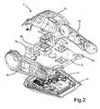
- Fig. 1illustrates the front part of the torso 1 of a manikin according to an embodiment of the present invention.
- the torsois comprised of a plurality of various components.
- imitated skin(not shown) will cover the shown parts, giving the manikin a realistic look.
- Fig. 2shows the same torso 1 in an exploded view, where more components can be seen.
- a top cover 1a(preferably compliant for resuscitation practice), side covers 1 b and a bottom cover 1c constitute the outer parts of the torso 1, in addition to the imitated skin.
- the bottom cover 1 cmakes the back part of the torso.
- Substantially parallel to the bottom part 1cis a manikin main board 3 arranged.
- the main board 3includes various electrical devices for the control of various manikin features. The main board 3 will be further described with reference to Fig. 5 .
- a cooling plate 5is arranged adjacent and over the main board 3.
- the cooling plate 5is made of aluminum, giving a light weight, yet structural robustness and high thermal conductivity.
- the cooling plate 5comprises attachment flanges 5a for the attachment of the manikin arms (not shown), a head (neck) attachment flange 5b and pelvis attachment flanges 5c. In stead of the pelvis attachment flanges 5c, one could also imagine a longer cooling plate 5 with thigh attachment flanges (not shown), or even one or more plates (or other elements) between the cooling plate 5 and thigh connections.
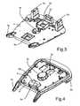
- Fig. 3 and 4show the upper and lower side of the cooling plate 5, respectively. With a distance from the plate perimeter there are two apertures 5d and 5e, for the through-flow of cooling air. In connection with the aperture 5e is a particular cooling section 5f of the cooling plate 5.
- the cooling section 5fis thermally coupled to a heat generating CPU through a flexible thermal conductor 5g.
- the CPUhas a particular cooling requirement. This will be described in more detail further below.
- a spring reception sectionin the form of a recess 5h for reception of a heart compression spring (not shown).
- the springis used to provide flexible resistance to the chest for heart compression practice. Without the plate 5, a dedicated structure with the mechanical strength for the reception of the spring would have to be provided. Thus, with the cooling plate 5, such an additional structure is advantageously avoided. With a good thermal connection between the cooling plate 5 and the spring, the spring could also conduct heat away from the plate 5.
- the cooling platecan preferably be a molded aluminum plate.
- the plurality of platescould preferably be thermally connected. They could for instance be hinged together.
- Fig. 5illustrates the manikin main board 3 shown in Fig. 2 in further detail.
- the perimeter of the main board 3is adapted to be fitted in the manikin torso 1.
- Situating the main board 3 in the back of the manikin torso 1is advantageous as this renders a large main board feasible.
- Close to one corner of the main board 3there are arranged two large resistors 3a for the dissipation of the electrical energy received from a defibrillator (not shown).
- the energy from a defibrillatoris dissipated in a controlled manner, and the nearby arranged cooling plate 5 will spread the generated heat throughout the torso 1.
- the use of a defibrillatorwill result in a periodic effect of 12 W dissipated in the resistors 3a. Under normal operation, this main board 3 will dissipate about 12 W.
- many of the most heat-generating componentsare arranged in the same area on the main board 3.
- One would think such an arrangementis a drawback, as the elements will heat each other.
- this configurationrenders it possible to direct the air flow from a fan 11 ( Fig. 6 ) directly onto the warmest components.
- Fig. 6is a cross section view showing the arrangement of the cooling plate 5 with respect to the manikin main board 3 and the bottom cover 1c.
- the top cover shown in Fig. 2is omitted in this figure.
- a layer of imitated skin 7is arranged around the covers 1 a, 1 b, 1c of the torso 1, substantially entrapping the air inside.
- the main board 3is arranged between the cooling plate 5 and the bottom cover 1c.
- a space 9is confined between the main board 3 and the cooling plate 5.
- the air in this space 9is thus heated by the various electric elements on the main board 3. This heat is then transferred to the cooling plate 5.
- the cooling plate 5is provided with two apertures 5d and 5e.
- a small fan 11is arranged in the aperture 5d to provide a flow of air into the space 9 through the aperture 5d. The air thus flows from the air space in the torso 1, into the space 9 between the main board 3 and the cooling plate 5, and finally out back through aperture 5d as heated air.
- the fan 11is advantageously controlled in order to provide air flow through the space 9 when necessary.
- the traineewill listen for body sounds, such as heart sounds or lunge sounds.
- the fan 11may produce a disturbing sound. Therefore, in an embodiment according to the invention, the manikin comprises sensors for sensing the presence of medical listening apparatuses, such as a stethoscope.
- the control of the fan 11is adapted to stop the fan 11 for a short period of time, in order to avoid disturbing such a listening action.
- the temperature of critical electrical elementsshould preferably be monitored in order to start the fan 11 before any critical temperatures are reached.
- the cooling plate 5has a particular cooling section 5f that is arranged directly adjacent a main board CPU 3b (central processing unit).
- the cooling section 5fis a plate section with a lower elevation than the opening of the aperture 5e, with the air flowing laterally over the cooling section 5f.
- the cooling section 5fis cooled particularly efficiently.
- the cooling section 5fis in thermal contact with the CPU 3b through a flexible thermal conductor 13a and an aluminum plate 13b. This direct thermal contact between the cooling plate 5 and the CPU 3b provides for an efficient removal of the heat generated by the CPU 3b.
- the cooling plate 5constitutes part of a Faraday cage that surrounds the main board 3.
- a Faraday cageis an efficient means to ensure such compatibility.
- the cooling plate 5made of metal, such as aluminum, it can be part of such a Faraday cage, thereby fulfilling yet another purpose.
- the Faraday cagemust be completed, preferably by the bottom cover 1 c, in order to encapsulate the main board 3 completely.
- the size of the cooling plateis at least 1 ⁇ 2 of the width of the torso.
- efficient heat transmission from the plate 5 to the air in the torso 1is provided.
- the large areaensures an even distribution of the heat inside the torso, making the torso skin more or less equally warm at all areas. Particular locations that are exceptionally warm will result in an unrealistic experience for the trainee.
Landscapes
- Engineering & Computer Science (AREA)
- Physics & Mathematics (AREA)
- General Physics & Mathematics (AREA)
- Mathematical Physics (AREA)
- Business, Economics & Management (AREA)
- Medicinal Chemistry (AREA)
- General Health & Medical Sciences (AREA)
- Algebra (AREA)
- Computational Mathematics (AREA)
- Chemical & Material Sciences (AREA)
- Mathematical Analysis (AREA)
- Mathematical Optimization (AREA)
- Health & Medical Sciences (AREA)
- Pure & Applied Mathematics (AREA)
- Medical Informatics (AREA)
- Educational Administration (AREA)
- Educational Technology (AREA)
- Theoretical Computer Science (AREA)
- Thermal Sciences (AREA)
- Microelectronics & Electronic Packaging (AREA)
- Thermotherapy And Cooling Therapy Devices (AREA)
- Instructional Devices (AREA)
- Toys (AREA)
- Manipulator (AREA)
- Cooling Or The Like Of Electrical Apparatus (AREA)
Description
- The present invention relates to a manikin for the training of medical practitioners and the like, comprising a means for dissipating heat generated by electrical and electromechanical devices inside the manikin. In particular, the invention relates to such a manikin comprising a cooling plate for said heat dissipation.
- Training manikins comprising electronics for the control of output and input parameters have been known for some time. Such parameters can include the sensing of actions performed by the medical trainee, such as a heart compression, or the actuation of an output parameter, such as a sound production or trembling using electromechanical drives. As such manikins are continually developed with more electronics inside, the produced heat inside the manikin increases. This heat must be lead away from the electronic devices and out of the manikin in order to prevent overheating inside. An overheating will result in malfunction of various devices, such as a CPU (central processing unit) for the control of said parameters.
- An obvious way to solve the problem would be to arrange a plurality of venting holes in the manikin, for leading the heat out of the manikin with through-flowing air. The heated air inside would then be substituted by fresh, colder external air. However, a manikin should provide a training experience as close as possible to real life scenario, and venting holes would not look and feel natural. In addition, through such holes, dirt and unwanted particles or organisms may enter the manikin. To ensure air exchange inside the manikin, a powerful fan may be needed, generating noise and additional heat production.
- Another way would be to obviate the problem by moving as much as possible of the heat generating electronics and actuators outside the manikin. With a manikin as described in patent publication
US 5,772,443 (Lampotang ), this could be a solution. Here, the manikin is placed on a bench with a multitude of instruments. However, with a manikin for use in a real life situation, not bound to a hospital or a particular training location, it is desirable that the manikin should be easily movable, without bringing along large amounts of connected equipment. The electronic devices and actuators should thus be arranged inside the manikin, not outside. This will also facilitate the set-up of a real life accident scenario, with an autonomous body (manikin) being arranged naturally at the scene of an accident, for instance. - Thus, by handling the heat generated by the electronic and electromechanical or other devices in a manikin, one avoids having to move devices outside of the manikin, while avoiding venting holes in the manikin skin. Of course, some devices will possibly be outside the manikin, such as a power supply or a communication interface, but the desired solution should not make it necessary to move any of the devices out of the manikin due to an overheating problem. Accordingly, the object of the present invention is to provide a manikin wherein such a solution is incorporated.
- The said object is solved by a manikin according to the present invention. Such a manikin is a manikin for the training of medical personnel and the like, comprising electrical circuitry for sensing of input parameters and controlling of output parameters. It comprises a plate comprising metal, for the conduction of heat generated by said electrical circuitry, away from said circuitry. Furthermore, the plate serves as a structural part of the manikin, as it is connected, directly or indirectly, to at least one of the group consisting of thighs, pelvis, neck (head), and arms. In addition, the plate constitutes at least a part of a Faraday cage surrounding a manikin main board.
- As will be appreciated from the discussion below, such a plate, or a cooling plate, has numerous advantages when used in a manikin of the above mentioned type.
- Advantageously, the said cooling plate aluminum, giving the plate a high structural strength and heat conduction characteristics. In addition, aluminum is a light and cheap metal, and not exposed to deterioration due to corrosion.
- By letting the plate serve as a substantial structural part, one obtains that the plate serves an additional purpose in addition to the cooling. Thus, the plate can constitute a central connection part of the manikin. For instance, a structural component of a manikin arm or leg/thigh may be connected directly to the plate. However, such a component could also be connected indirectly to the plate, through additional structure bridging the plate and the body part. For example, the plate can be connected to a pelvis component, which also is connected to the legs or thighs of the manikin.
- According to an advantageous embodiment of the present invention, the cooling plate is arranged substantially parallel to an electrical main board in the manikin, for dissipation of heat generated by said main board. In this way, the heat conduction from the elements on the main board is efficiently provided to the cooling plate. To achieve even more efficient cooling of the elements on the main board, the plate is arranged for circulation of air from one side of the plate to the other, providing air flow over the said elements.
- In a particularly advantageous embodiment, the plate comprises at least one aperture for the flow-through of cooling air. Preferably, a fan is arranged in association to the cooling plate, for providing air flow through at least one of said apertures. Also, the plate is arranged in such way that cooling air is flowing in a space between the plate and said main board, for directing the air flow over the elements on the main board.
- For efficient cooling of a particularly heat generating or critical element, such as a CPU, the element can be arranged directly opposite an aperture in the cooling plate, for directed air flow over the said element. Another possible measure enhancing the cooling efficiency of such an element is to arrange a part of the cooling plate in thermal contact with said element.
- Characteristic to an advantageous embodiment of the present invention, substantially all heat produced in the manikin is lead to the surroundings by heat conduction through the exterior parts of the manikin, such as imitated skin. In this way, unrealistic venting holes in the exterior parts of the manikin (skin) is avoided, resulting in a more authentic training experience for the trainee.
- Having the cooling plate comprising metal and constituting a part of a Faraday cage surrounding a manikin main board, makes the cooling plate partly fulfilling yet another object. As the manikin main board holds electronic circuitry of many kinds, a Faraday cage should be arranged around it to comply with EMC regulations (electromagnetic compatibility). Such regulations may be particularly stringent, since the manikin should be allowed for use in hospitals where sensitive electronic equipment is used. When the cooling plate is adapted with one or more apertures for air flow, the apertures should preferably be covered with a metal grid for blocking electromagnetic waves, but letting air flow through freely.
- In a particular embodiment, the manikin according to the present invention is provided with sensing means for sensing of the presence of listening apparatuses, such as a stethoscope. In addition, the fan is adapted to be switched off during the presence of such a listening apparatus. Since the fan may produce some noise when running, this feature ensures that the fan does not disturb a listening sequence.
- Preferably, the cooling plate is arranged in the manikin torso and has a width of at least ½ of the width of the torso. Having such a large sized plate results in a wide spreading of the heat that shall be conducted out of the manikin, substantially through the skin. The wide spreading of the heat results in no exceptionally warm locations on the skin, and that the need for ventilating holes is avoided.
- According to another preferable embodiment of the present invention, the cooling plate is arranged with a reception section for a heart compression resistance spring. Such a spring can be arranged in the manikin for providing resistance to the chest when it is pushed down as in a heart compression training drill. By incorporating this feature into the cooling plate, one avoids having a dedicated structural element for the same purpose.
- In stead of having only one plate arranged in the manikin, one embodiment of the invention applies two or more plates. The plates may preferably have a thermal connection. They may for instance be hinged together with a heat conducting hinge joint.
- As will be appreciated by the summarized description of the invention and the following example of embodiment according to the invention, the invention has numerous advantages:
- The effective cooling plate results in a minimum use of fan for cooling the heat generating components. Depending on the temperature of the surroundings, a fan may not have to be used at all. If use of a fan is necessary, the large size of the cooling plate and the effective set-up result in a minimum need for such use. As mentioned above, manikins of the described kind can be required to produce no or little noise, except for any desired or produced noise for medical training purposes.
- The cooling plate meets structural requirements.
- Due to the large size of the plate, the produced heat can be lead out by thermal conduction through the manikin skin. No venting apertures needed and no exceptionally warm locations on the skin surface will arise.
- The cooling plate can provide a strong structural reception section for a heart compression resistance spring, omitting a dedicated structure for this purpose.
- The cooling plate contributes in meeting electromagnetic compatibility (EMC) requirements, by constituting at least a part of a Faraday cage.
- In the following, a detailed example of an embodiment of the present invention is given with reference to the drawings, in which
Fig. 1 is a view of the torso section of a manikin according to the present invention;Fig. 2 is an exploded perspective view of the torso section of a manikin according to the present invention;Fig. 3 is a perspective view of a cooling plate arranged in a manikin according to an embodiment of the present invention;Fig. 4 is a perspective view of the cooling plate ofFig. 3 , seen from a different angle;Fig. 5 is a perspective view of a main electrical circuit board, adapted to be arranged inside the torso;Fig. 6 is a cross section view through the torso, showing the cooling plate and cooling air flowing over some heat generating electric devices; andFig. 7 is an enlarged cross section view showing a particular set-up for the cooling of a CPU.Fig. 1 illustrates the front part of thetorso 1 of a manikin according to an embodiment of the present invention. As shown, the torso is comprised of a plurality of various components. In use, imitated skin (not shown) will cover the shown parts, giving the manikin a realistic look.Fig. 2 shows thesame torso 1 in an exploded view, where more components can be seen. Atop cover 1a (preferably compliant for resuscitation practice), side covers 1 b and abottom cover 1c constitute the outer parts of thetorso 1, in addition to the imitated skin. Thebottom cover 1 c makes the back part of the torso. Substantially parallel to thebottom part 1c is a manikinmain board 3 arranged. Themain board 3 includes various electrical devices for the control of various manikin features. Themain board 3 will be further described with reference toFig. 5 .- A
cooling plate 5 is arranged adjacent and over themain board 3. In this embodiment, thecooling plate 5 is made of aluminum, giving a light weight, yet structural robustness and high thermal conductivity. Thecooling plate 5 comprisesattachment flanges 5a for the attachment of the manikin arms (not shown), a head (neck)attachment flange 5b and pelvis attachment flanges 5c. In stead of thepelvis attachment flanges 5c, one could also imagine a longer coolingplate 5 with thigh attachment flanges (not shown), or even one or more plates (or other elements) between the coolingplate 5 and thigh connections. Fig. 3 and 4 show the upper and lower side of thecooling plate 5, respectively. With a distance from the plate perimeter there are twoapertures aperture 5e is aparticular cooling section 5f of thecooling plate 5. Thecooling section 5f is thermally coupled to a heat generating CPU through a flexiblethermal conductor 5g. The CPU has a particular cooling requirement. This will be described in more detail further below.- Centrally arranged in the
plate 5 is a spring reception section in the form of arecess 5h for reception of a heart compression spring (not shown). The spring is used to provide flexible resistance to the chest for heart compression practice. Without theplate 5, a dedicated structure with the mechanical strength for the reception of the spring would have to be provided. Thus, with thecooling plate 5, such an additional structure is advantageously avoided. With a good thermal connection between the coolingplate 5 and the spring, the spring could also conduct heat away from theplate 5. The cooling plate can preferably be a molded aluminum plate. - It should be noted that instead of having one single cooling plate, more plates could also be used in the same way. The plurality of plates could preferably be thermally connected. They could for instance be hinged together.
Fig. 5 illustrates the manikinmain board 3 shown inFig. 2 in further detail. The perimeter of themain board 3 is adapted to be fitted in themanikin torso 1. Situating themain board 3 in the back of themanikin torso 1 is advantageous as this renders a large main board feasible. Of course, one could also arrange a plurality of circuit boards, but this would be unnecessary cumbersome and expensive. Close to one corner of themain board 3 there are arranged twolarge resistors 3a for the dissipation of the electrical energy received from a defibrillator (not shown). Thus, with the use of theseresistors 3a, the energy from a defibrillator is dissipated in a controlled manner, and the nearby arranged coolingplate 5 will spread the generated heat throughout thetorso 1. In this embodiment, the use of a defibrillator will result in a periodic effect of 12 W dissipated in theresistors 3a. Under normal operation, thismain board 3 will dissipate about 12 W.- Preferably, many of the most heat-generating components are arranged in the same area on the
main board 3. One would think such an arrangement is a drawback, as the elements will heat each other. However, this configuration renders it possible to direct the air flow from a fan 11 (Fig. 6 ) directly onto the warmest components. Fig. 6 is a cross section view showing the arrangement of thecooling plate 5 with respect to the manikinmain board 3 and thebottom cover 1c. For simplicity, the top cover shown inFig. 2 is omitted in this figure. A layer of imitated skin 7 is arranged around thecovers torso 1, substantially entrapping the air inside.- The
main board 3 is arranged between the coolingplate 5 and thebottom cover 1c. As can be appreciated fromFig. 6 , a space 9 is confined between themain board 3 and thecooling plate 5. The air in this space 9 is thus heated by the various electric elements on themain board 3. This heat is then transferred to thecooling plate 5. In addition, as briefly mentioned above, thecooling plate 5 is provided with twoapertures small fan 11 is arranged in theaperture 5d to provide a flow of air into the space 9 through theaperture 5d. The air thus flows from the air space in thetorso 1, into the space 9 between themain board 3 and thecooling plate 5, and finally out back throughaperture 5d as heated air. Thus, (relatively) cool air is drawn into the space 9 and flowed past heat generating electric elements which then are cooled. It should be noted that this is a closed loop. Air is not drawn from outside of the manikin, but from the space inside it. The air is thus heated in the space 9 between the coolingplate 5 and themain board 3, and cooled off outside this space 9, by transferring heat to the exterior parts of the manikin, such as the skin 7. The heat is conducted out of the manikin through the skin 7. - The
fan 11 is advantageously controlled in order to provide air flow through the space 9 when necessary. During some training scenarios using a manikin according to the invention, the trainee will listen for body sounds, such as heart sounds or lunge sounds. In some cases, thefan 11 may produce a disturbing sound. Therefore, in an embodiment according to the invention, the manikin comprises sensors for sensing the presence of medical listening apparatuses, such as a stethoscope. When sensing such presence, the control of thefan 11 is adapted to stop thefan 11 for a short period of time, in order to avoid disturbing such a listening action. However, the temperature of critical electrical elements should preferably be monitored in order to start thefan 11 before any critical temperatures are reached. - In an especially advantageous embodiment, as shown in
Fig. 6 , thecooling plate 5 has aparticular cooling section 5f that is arranged directly adjacent amain board CPU 3b (central processing unit). As perhaps best shown inFig. 3 and 4 , thecooling section 5f is a plate section with a lower elevation than the opening of theaperture 5e, with the air flowing laterally over thecooling section 5f. Thus, thecooling section 5f is cooled particularly efficiently. As shown in further detail inFig. 7 , thecooling section 5f is in thermal contact with theCPU 3b through a flexiblethermal conductor 13a and analuminum plate 13b. This direct thermal contact between the coolingplate 5 and theCPU 3b provides for an efficient removal of the heat generated by theCPU 3b. - In a preferable embodiment of the present invention, the
cooling plate 5 constitutes part of a Faraday cage that surrounds themain board 3. As briefly mentioned above, there may be stringent EMC-requirements (electromagnetic compatibility) for a manikin of the type according to the invention. A Faraday cage is an efficient means to ensure such compatibility. Having thecooling plate 5 made of metal, such as aluminum, it can be part of such a Faraday cage, thereby fulfilling yet another purpose. Of course, the Faraday cage must be completed, preferably by thebottom cover 1 c, in order to encapsulate themain board 3 completely. - Preferably, the size of the cooling plate is at least ½ of the width of the torso. By arranging a cooling plate with a large area, efficient heat transmission from the
plate 5 to the air in thetorso 1 is provided. Also, the large area ensures an even distribution of the heat inside the torso, making the torso skin more or less equally warm at all areas. Particular locations that are exceptionally warm will result in an unrealistic experience for the trainee.
Claims (15)
- Manikin for the training of medical personnel and the like, comprising electrical circuitry for sensing of input parameters and controlling of output parameters,characterized in that- it comprises a plate (5) comprising metal, for the conduction of heat generated by said electrical circuitry, away from said circuitry,- the said plate serving as a structural part, as it is connected, directly or indirectly, to at least one of the group consisting of thighs, pelvis, neck (head), and arms;- the said plate constitutes at least a part of a Faraday cage surrounding a manikin main board (3).
- Manikin according to any one of the preceding claims,characterized in that said plate (5) is arranged substantially parallel to said electrical main board, for dissipation of heat generated by said main board (3).
- Manikin according to any one of the preceding claims,characterized in that the plate (5) is arranged for circulation of air from one side of the plate to the other.
- Manikin according to any one of the preceding claims,characterized in that said plate (5) comprises at least one aperture (5d, 5e) for the flow-through of cooling air.
- Manikin according to claim 4,characterized in that a fan (11) is arranged in association to said plate, for providing air flow through at least one of said apertures. (5d, 5e).
- Manikin according any one of claims 3-5,characterized in that said plate (5) is arranged in such way that cooling air is flowing in a space (9) between the plate (5) and said main board (3).
- Manikin according to any one of claims 4-6,characterized in that an element on the main board (3) that generates particularly much heat, and an aperture (5e) in the cooling plate are arranged in corresponding locations, so that cooling air is flown directly on the element.
- Manikin according to any one of the preceding claims,characterized in that said plate (5) is in thermal contact with heat generating circuitry.
- Manikin according to any one of the preceding claims,characterized in that substantially all heat produced in the manikin is lead to the surroundings by heat conduction through the exterior parts of the manikin, such as imitated skin (7).
- Manikin according to claim 4,characterized in that said aperture (5d, 5e) is covered with a metal grid, which grid constitutes part of said Faraday cage, and through which air can flow freely.
- Manikin according to claim 5,characterized in that it is provided with sensing means for sensing of the presence of listening apparatuses, such as a stethoscope, and that the fan (11) is adapted to be switched off during the presence of such a listening apparatus.
- Manikin according to any one of the preceding claims,characterized in that said plate (5) is arranged in the manikin torso (1) and has a width of at least ½ of the width of the torso.
- Manikin according to any one of the preceding claims,characterized in that said plate (5) is arranged with a reception section for a heart compression resistance spring.
- Manikin according to any one of the preceding claims,characterized in that said plate (5) is one of a plurality of such cooling plates.
- Manikin according to claim 14,characterized in that at least two of the plates are thermally connected.
Applications Claiming Priority (3)
| Application Number | Priority Date | Filing Date | Title |
|---|---|---|---|
| NO20080200ANO20080200L (en) | 2008-01-11 | 2008-01-11 | Mannequin with dress plate |
| US643908P | 2008-01-14 | 2008-01-14 | |
| PCT/NO2009/000012WO2009088305A1 (en) | 2008-01-11 | 2009-01-09 | Manikin with cooling plate |
Publications (3)
| Publication Number | Publication Date |
|---|---|
| EP2243130A1 EP2243130A1 (en) | 2010-10-27 |
| EP2243130A4 EP2243130A4 (en) | 2014-06-11 |
| EP2243130B1true EP2243130B1 (en) | 2015-07-22 |
Family
ID=40853271
Family Applications (1)
| Application Number | Title | Priority Date | Filing Date |
|---|---|---|---|
| EP09700225.7ANot-in-forceEP2243130B1 (en) | 2008-01-11 | 2009-01-09 | Manikin with cooling plate |
Country Status (7)
| Country | Link |
|---|---|
| US (1) | US8851898B2 (en) |
| EP (1) | EP2243130B1 (en) |
| JP (1) | JP5303573B2 (en) |
| CN (1) | CN101911152B (en) |
| AU (1) | AU2009203224B2 (en) |
| NO (1) | NO20080200L (en) |
| WO (1) | WO2009088305A1 (en) |
Families Citing this family (4)
| Publication number | Priority date | Publication date | Assignee | Title |
|---|---|---|---|---|
| NO20080200L (en)* | 2008-01-11 | 2009-07-13 | Laerdal Medical As | Mannequin with dress plate |
| WO2012035129A2 (en) | 2010-09-17 | 2012-03-22 | Laerdal Medical As | Manikin with cpr hand position detection |
| US9576503B2 (en) | 2013-12-27 | 2017-02-21 | Seattle Children's Hospital | Simulation cart |
| US11074832B2 (en)* | 2017-08-16 | 2021-07-27 | Tellyes Scientific Inc. | Warming of simulated blood using waste heat generated by electronic components |
Family Cites Families (31)
| Publication number | Priority date | Publication date | Assignee | Title |
|---|---|---|---|---|
| US2772664A (en) | 1953-12-11 | 1956-12-04 | Exxon Research Engineering Co | Fluid flow meter |
| US3209469A (en)* | 1962-03-07 | 1965-10-05 | Harold M James | External cardiac massage training device |
| US3520071A (en)* | 1968-01-29 | 1970-07-14 | Aerojet General Co | Anesthesiological training simulator |
| DE1962083A1 (en) | 1969-12-11 | 1971-06-16 | Laerdal A S | Exercise device for resuscitation through ventilation and external cardiac massage |
| US3657925A (en) | 1970-06-01 | 1972-04-25 | Int Rectifier Corp | Positive displacement flowmeter |
| USRE29317E (en) | 1973-01-29 | 1977-07-26 | Michigan Instruments, Inc. | Pneumatic lung analog |
| SE430925B (en) | 1977-11-09 | 1983-12-19 | Gambro Lundia Ab | FLODESMETARE |
| DE3049583C2 (en) | 1980-12-31 | 1984-08-16 | Obermayer, Anton, Dipl.-Ing., 7954 Bad Wurzach | Breathing device for the technical training of doctors, nurses and nursing staff |
| US4430893A (en) | 1981-11-16 | 1984-02-14 | Michigan Instruments, Inc. | Pneumatic lung analog for simulation of spontaneous breathing and for testing of ventilatory devices used with spontaneously breathing patients |
| US4430890A (en)* | 1982-05-14 | 1984-02-14 | The United States Of America As Represented By The Secretary Of The Navy | Two layer hydraulic analogy method for testing supersonic gas flows with shock waves |
| GB2191884B (en)* | 1986-06-17 | 1990-05-30 | Secr Defence | Improvements in manikins |
| US5137459A (en)* | 1989-10-28 | 1992-08-11 | Mathias Zirm | Device for conducting experimental eye operations |
| US5584701A (en)* | 1992-05-13 | 1996-12-17 | University Of Florida Research Foundation, Incorporated | Self regulating lung for simulated medical procedures |
| JPH08190340A (en) | 1995-01-10 | 1996-07-23 | Yagami:Kk | Resuscitation education human body model |
| US5873731A (en) | 1995-10-20 | 1999-02-23 | Eagle Simulation, Inc. | Patient drug recognition system |
| US6443735B1 (en) | 1996-05-08 | 2002-09-03 | Gaumard Scientific, Inc. | Computerized education system for teaching patient care |
| US7811090B2 (en)* | 1996-05-08 | 2010-10-12 | Gaumard Scientific Company, Inc. | Interactive education system for teaching patient care |
| US8696362B2 (en)* | 1996-05-08 | 2014-04-15 | Gaumard Scientific Company, Inc. | Interactive education system for teaching patient care |
| US6503087B1 (en)* | 1996-05-08 | 2003-01-07 | Gaumard Scientific, Inc. | Interactive education system for teaching patient care |
| GB2339323A (en)* | 1998-03-05 | 2000-01-19 | Laerdal Asmund S Medical Gmbh | Cardiopulmonary resuscitation (CPR) training model of the human body |
| IL126783A0 (en)* | 1998-03-05 | 1999-08-17 | M T R E Advanced Technology Lt | System and method for heat control of a living body |
| JP2000277237A (en)* | 1999-03-24 | 2000-10-06 | Komatsu Ltd | Substrate temperature control plate and substrate temperature control device including the same |
| NO310135B1 (en)* | 1999-05-31 | 2001-05-28 | Laerdal Medical As | System for measuring and applying parameters when performing chest compression in the course of a life-saving situation or training situation as well as applications |
| US6269003B1 (en)* | 1999-12-27 | 2001-07-31 | Wei Wen-Chen | Heat dissipater structure |
| CN1363205A (en) | 2000-02-17 | 2002-08-07 | 皇家菲利浦电子有限公司 | Heat sink with an integrated component clamping device |
| US7976313B2 (en)* | 2000-08-17 | 2011-07-12 | Gaumard Scientific Company, Inc. | Interactive education system for teaching patient care |
| US6577504B1 (en)* | 2000-08-30 | 2003-06-10 | Intel Corporation | Integrated heat sink for different size components with EMI suppression features |
| JP3818084B2 (en)* | 2000-12-22 | 2006-09-06 | 日立電線株式会社 | Cooling plate and manufacturing method thereof, and sputtering target and manufacturing method thereof |
| NO319063B1 (en) | 2003-10-06 | 2005-06-13 | Laerdal Medical As | Medical patient simulator |
| US20090035740A1 (en)* | 2007-07-30 | 2009-02-05 | Monster Medic, Inc. | Systems and methods for remote controlled interactive training and certification |
| NO20080200L (en)* | 2008-01-11 | 2009-07-13 | Laerdal Medical As | Mannequin with dress plate |
- 2008
- 2008-01-11NONO20080200Apatent/NO20080200L/ennot_activeApplication Discontinuation
- 2009
- 2009-01-09CNCN200980101574.5Apatent/CN101911152B/ennot_activeExpired - Fee Related
- 2009-01-09EPEP09700225.7Apatent/EP2243130B1/ennot_activeNot-in-force
- 2009-01-09USUS12/810,039patent/US8851898B2/ennot_activeExpired - Fee Related
- 2009-01-09JPJP2010542188Apatent/JP5303573B2/ennot_activeExpired - Fee Related
- 2009-01-09AUAU2009203224Apatent/AU2009203224B2/ennot_activeCeased
- 2009-01-09WOPCT/NO2009/000012patent/WO2009088305A1/enactiveApplication Filing
Also Published As
| Publication number | Publication date |
|---|---|
| CN101911152B (en) | 2012-08-22 |
| EP2243130A4 (en) | 2014-06-11 |
| AU2009203224B2 (en) | 2014-02-20 |
| JP5303573B2 (en) | 2013-10-02 |
| US20100291523A1 (en) | 2010-11-18 |
| EP2243130A1 (en) | 2010-10-27 |
| US8851898B2 (en) | 2014-10-07 |
| AU2009203224A1 (en) | 2009-07-16 |
| WO2009088305A1 (en) | 2009-07-16 |
| NO20080200L (en) | 2009-07-13 |
| JP2011509439A (en) | 2011-03-24 |
| CN101911152A (en) | 2010-12-08 |
Similar Documents
| Publication | Publication Date | Title |
|---|---|---|
| EP2243130B1 (en) | Manikin with cooling plate | |
| JP5011016B2 (en) | Power converter | |
| EP1656009B1 (en) | Power adapter with fan assembly | |
| US7821268B2 (en) | Electronic device for a magnetic resonance apparatus | |
| JP2006524846A (en) | Computer | |
| GB0403382D0 (en) | Electrical apparatus and cooling system | |
| KR20160022296A (en) | Device cover for thermal management | |
| US20240090182A1 (en) | Passive Heat Dissipation Power Supply for IT Equipment | |
| JP5196322B2 (en) | Magnetic stimulator for urinary incontinence treatment | |
| RU203464U1 (en) | Heat-loaded electronic device | |
| TW592029B (en) | Electronic apparatus with natural convection structure | |
| FR3086494B1 (en) | SYSTEM OF MODULAR AND UNIVERSAL ELECTRICAL BANDS | |
| JP5611116B2 (en) | Power supply | |
| JP5309243B2 (en) | Power converter | |
| US20040237570A1 (en) | Mobile satellite link terminal | |
| US12078691B2 (en) | Housing assembly for accommodating printed circuit boards | |
| EP1517329A3 (en) | Cooling device and electrical equipment equipped with the cooling device | |
| JP2015096010A (en) | Electronic unit | |
| JP6213356B2 (en) | Power supply | |
| JP2012044038A (en) | Heat dissipation structure of electronic device | |
| JP2014146769A (en) | Housing structure of electronic apparatus and power conditioner | |
| CN213484611U (en) | Motor mounting seat | |
| CN219941715U (en) | Strength training machine | |
| CN216123388U (en) | Beauty instrument circuit board convenient to heat dissipation | |
| JP4829276B2 (en) | Electronics |
Legal Events
| Date | Code | Title | Description |
|---|---|---|---|
| PUAI | Public reference made under article 153(3) epc to a published international application that has entered the european phase | Free format text:ORIGINAL CODE: 0009012 | |
| 17P | Request for examination filed | Effective date:20100811 | |
| AK | Designated contracting states | Kind code of ref document:A1 Designated state(s):AT BE BG CH CY CZ DE DK EE ES FI FR GB GR HR HU IE IS IT LI LT LU LV MC MK MT NL NO PL PT RO SE SI SK TR | |
| AX | Request for extension of the european patent | Extension state:AL BA RS | |
| DAX | Request for extension of the european patent (deleted) | ||
| A4 | Supplementary search report drawn up and despatched | Effective date:20140509 | |
| RIC1 | Information provided on ipc code assigned before grant | Ipc:G09B 23/28 20060101AFI20140505BHEP Ipc:G09B 23/30 20060101ALI20140505BHEP | |
| GRAP | Despatch of communication of intention to grant a patent | Free format text:ORIGINAL CODE: EPIDOSNIGR1 | |
| RIC1 | Information provided on ipc code assigned before grant | Ipc:H05K 7/20 20060101ALI20150310BHEP Ipc:G09B 23/30 20060101AFI20150310BHEP | |
| INTG | Intention to grant announced | Effective date:20150409 | |
| GRAS | Grant fee paid | Free format text:ORIGINAL CODE: EPIDOSNIGR3 | |
| GRAA | (expected) grant | Free format text:ORIGINAL CODE: 0009210 | |
| AK | Designated contracting states | Kind code of ref document:B1 Designated state(s):AT BE BG CH CY CZ DE DK EE ES FI FR GB GR HR HU IE IS IT LI LT LU LV MC MK MT NL NO PL PT RO SE SI SK TR | |
| REG | Reference to a national code | Ref country code:GB Ref legal event code:FG4D | |
| REG | Reference to a national code | Ref country code:CH Ref legal event code:EP | |
| REG | Reference to a national code | Ref country code:IE Ref legal event code:FG4D | |
| REG | Reference to a national code | Ref country code:AT Ref legal event code:REF Ref document number:738290 Country of ref document:AT Kind code of ref document:T Effective date:20150815 | |
| REG | Reference to a national code | Ref country code:DE Ref legal event code:R096 Ref document number:602009032326 Country of ref document:DE | |
| REG | Reference to a national code | Ref country code:FR Ref legal event code:PLFP Year of fee payment:8 | |
| REG | Reference to a national code | Ref country code:AT Ref legal event code:MK05 Ref document number:738290 Country of ref document:AT Kind code of ref document:T Effective date:20150722 | |
| REG | Reference to a national code | Ref country code:LT Ref legal event code:MG4D | |
| REG | Reference to a national code | Ref country code:NL Ref legal event code:MP Effective date:20150722 | |
| PG25 | Lapsed in a contracting state [announced via postgrant information from national office to epo] | Ref country code:LT Free format text:LAPSE BECAUSE OF FAILURE TO SUBMIT A TRANSLATION OF THE DESCRIPTION OR TO PAY THE FEE WITHIN THE PRESCRIBED TIME-LIMIT Effective date:20150722 Ref country code:NO Free format text:LAPSE BECAUSE OF FAILURE TO SUBMIT A TRANSLATION OF THE DESCRIPTION OR TO PAY THE FEE WITHIN THE PRESCRIBED TIME-LIMIT Effective date:20151022 Ref country code:LV Free format text:LAPSE BECAUSE OF FAILURE TO SUBMIT A TRANSLATION OF THE DESCRIPTION OR TO PAY THE FEE WITHIN THE PRESCRIBED TIME-LIMIT Effective date:20150722 Ref country code:GR Free format text:LAPSE BECAUSE OF FAILURE TO SUBMIT A TRANSLATION OF THE DESCRIPTION OR TO PAY THE FEE WITHIN THE PRESCRIBED TIME-LIMIT Effective date:20151023 Ref country code:FI Free format text:LAPSE BECAUSE OF FAILURE TO SUBMIT A TRANSLATION OF THE DESCRIPTION OR TO PAY THE FEE WITHIN THE PRESCRIBED TIME-LIMIT Effective date:20150722 | |
| PG25 | Lapsed in a contracting state [announced via postgrant information from national office to epo] | Ref country code:SE Free format text:LAPSE BECAUSE OF FAILURE TO SUBMIT A TRANSLATION OF THE DESCRIPTION OR TO PAY THE FEE WITHIN THE PRESCRIBED TIME-LIMIT Effective date:20150722 Ref country code:HR Free format text:LAPSE BECAUSE OF FAILURE TO SUBMIT A TRANSLATION OF THE DESCRIPTION OR TO PAY THE FEE WITHIN THE PRESCRIBED TIME-LIMIT Effective date:20150722 Ref country code:IS Free format text:LAPSE BECAUSE OF FAILURE TO SUBMIT A TRANSLATION OF THE DESCRIPTION OR TO PAY THE FEE WITHIN THE PRESCRIBED TIME-LIMIT Effective date:20151122 Ref country code:AT Free format text:LAPSE BECAUSE OF FAILURE TO SUBMIT A TRANSLATION OF THE DESCRIPTION OR TO PAY THE FEE WITHIN THE PRESCRIBED TIME-LIMIT Effective date:20150722 Ref country code:PT Free format text:LAPSE BECAUSE OF FAILURE TO SUBMIT A TRANSLATION OF THE DESCRIPTION OR TO PAY THE FEE WITHIN THE PRESCRIBED TIME-LIMIT Effective date:20151123 Ref country code:ES Free format text:LAPSE BECAUSE OF FAILURE TO SUBMIT A TRANSLATION OF THE DESCRIPTION OR TO PAY THE FEE WITHIN THE PRESCRIBED TIME-LIMIT Effective date:20150722 Ref country code:PL Free format text:LAPSE BECAUSE OF FAILURE TO SUBMIT A TRANSLATION OF THE DESCRIPTION OR TO PAY THE FEE WITHIN THE PRESCRIBED TIME-LIMIT Effective date:20150722 | |
| PGFP | Annual fee paid to national office [announced via postgrant information from national office to epo] | Ref country code:FR Payment date:20151208 Year of fee payment:8 | |
| REG | Reference to a national code | Ref country code:DE Ref legal event code:R097 Ref document number:602009032326 Country of ref document:DE | |
| PG25 | Lapsed in a contracting state [announced via postgrant information from national office to epo] | Ref country code:SK Free format text:LAPSE BECAUSE OF FAILURE TO SUBMIT A TRANSLATION OF THE DESCRIPTION OR TO PAY THE FEE WITHIN THE PRESCRIBED TIME-LIMIT Effective date:20150722 Ref country code:IT Free format text:LAPSE BECAUSE OF FAILURE TO SUBMIT A TRANSLATION OF THE DESCRIPTION OR TO PAY THE FEE WITHIN THE PRESCRIBED TIME-LIMIT Effective date:20150722 Ref country code:DK Free format text:LAPSE BECAUSE OF FAILURE TO SUBMIT A TRANSLATION OF THE DESCRIPTION OR TO PAY THE FEE WITHIN THE PRESCRIBED TIME-LIMIT Effective date:20150722 Ref country code:EE Free format text:LAPSE BECAUSE OF FAILURE TO SUBMIT A TRANSLATION OF THE DESCRIPTION OR TO PAY THE FEE WITHIN THE PRESCRIBED TIME-LIMIT Effective date:20150722 Ref country code:CZ Free format text:LAPSE BECAUSE OF FAILURE TO SUBMIT A TRANSLATION OF THE DESCRIPTION OR TO PAY THE FEE WITHIN THE PRESCRIBED TIME-LIMIT Effective date:20150722 | |
| PGFP | Annual fee paid to national office [announced via postgrant information from national office to epo] | Ref country code:DE Payment date:20160105 Year of fee payment:8 | |
| PLBE | No opposition filed within time limit | Free format text:ORIGINAL CODE: 0009261 | |
| STAA | Information on the status of an ep patent application or granted ep patent | Free format text:STATUS: NO OPPOSITION FILED WITHIN TIME LIMIT | |
| PG25 | Lapsed in a contracting state [announced via postgrant information from national office to epo] | Ref country code:BE Free format text:LAPSE BECAUSE OF NON-PAYMENT OF DUE FEES Effective date:20160131 Ref country code:RO Free format text:LAPSE BECAUSE OF FAILURE TO SUBMIT A TRANSLATION OF THE DESCRIPTION OR TO PAY THE FEE WITHIN THE PRESCRIBED TIME-LIMIT Effective date:20150722 | |
| PGFP | Annual fee paid to national office [announced via postgrant information from national office to epo] | Ref country code:GB Payment date:20160106 Year of fee payment:8 | |
| 26N | No opposition filed | Effective date:20160425 | |
| PG25 | Lapsed in a contracting state [announced via postgrant information from national office to epo] | Ref country code:LU Free format text:LAPSE BECAUSE OF FAILURE TO SUBMIT A TRANSLATION OF THE DESCRIPTION OR TO PAY THE FEE WITHIN THE PRESCRIBED TIME-LIMIT Effective date:20160109 Ref country code:SI Free format text:LAPSE BECAUSE OF FAILURE TO SUBMIT A TRANSLATION OF THE DESCRIPTION OR TO PAY THE FEE WITHIN THE PRESCRIBED TIME-LIMIT Effective date:20150722 | |
| REG | Reference to a national code | Ref country code:CH Ref legal event code:PL | |
| PG25 | Lapsed in a contracting state [announced via postgrant information from national office to epo] | Ref country code:MC Free format text:LAPSE BECAUSE OF FAILURE TO SUBMIT A TRANSLATION OF THE DESCRIPTION OR TO PAY THE FEE WITHIN THE PRESCRIBED TIME-LIMIT Effective date:20150722 | |
| PG25 | Lapsed in a contracting state [announced via postgrant information from national office to epo] | Ref country code:LI Free format text:LAPSE BECAUSE OF NON-PAYMENT OF DUE FEES Effective date:20160131 Ref country code:CH Free format text:LAPSE BECAUSE OF NON-PAYMENT OF DUE FEES Effective date:20160131 | |
| REG | Reference to a national code | Ref country code:IE Ref legal event code:MM4A | |
| PG25 | Lapsed in a contracting state [announced via postgrant information from national office to epo] | Ref country code:BE Free format text:LAPSE BECAUSE OF FAILURE TO SUBMIT A TRANSLATION OF THE DESCRIPTION OR TO PAY THE FEE WITHIN THE PRESCRIBED TIME-LIMIT Effective date:20150722 | |
| PG25 | Lapsed in a contracting state [announced via postgrant information from national office to epo] | Ref country code:IE Free format text:LAPSE BECAUSE OF NON-PAYMENT OF DUE FEES Effective date:20160109 | |
| PG25 | Lapsed in a contracting state [announced via postgrant information from national office to epo] | Ref country code:NL Free format text:LAPSE BECAUSE OF FAILURE TO SUBMIT A TRANSLATION OF THE DESCRIPTION OR TO PAY THE FEE WITHIN THE PRESCRIBED TIME-LIMIT Effective date:20150722 | |
| REG | Reference to a national code | Ref country code:DE Ref legal event code:R119 Ref document number:602009032326 Country of ref document:DE | |
| PG25 | Lapsed in a contracting state [announced via postgrant information from national office to epo] | Ref country code:MT Free format text:LAPSE BECAUSE OF FAILURE TO SUBMIT A TRANSLATION OF THE DESCRIPTION OR TO PAY THE FEE WITHIN THE PRESCRIBED TIME-LIMIT Effective date:20150722 | |
| GBPC | Gb: european patent ceased through non-payment of renewal fee | Effective date:20170109 | |
| REG | Reference to a national code | Ref country code:FR Ref legal event code:ST Effective date:20170929 | |
| PG25 | Lapsed in a contracting state [announced via postgrant information from national office to epo] | Ref country code:FR Free format text:LAPSE BECAUSE OF NON-PAYMENT OF DUE FEES Effective date:20170131 | |
| PG25 | Lapsed in a contracting state [announced via postgrant information from national office to epo] | Ref country code:DE Free format text:LAPSE BECAUSE OF NON-PAYMENT OF DUE FEES Effective date:20170801 Ref country code:GB Free format text:LAPSE BECAUSE OF NON-PAYMENT OF DUE FEES Effective date:20170109 | |
| PG25 | Lapsed in a contracting state [announced via postgrant information from national office to epo] | Ref country code:HU Free format text:LAPSE BECAUSE OF FAILURE TO SUBMIT A TRANSLATION OF THE DESCRIPTION OR TO PAY THE FEE WITHIN THE PRESCRIBED TIME-LIMIT; INVALID AB INITIO Effective date:20090109 Ref country code:CY Free format text:LAPSE BECAUSE OF FAILURE TO SUBMIT A TRANSLATION OF THE DESCRIPTION OR TO PAY THE FEE WITHIN THE PRESCRIBED TIME-LIMIT Effective date:20150722 | |
| PG25 | Lapsed in a contracting state [announced via postgrant information from national office to epo] | Ref country code:MK Free format text:LAPSE BECAUSE OF FAILURE TO SUBMIT A TRANSLATION OF THE DESCRIPTION OR TO PAY THE FEE WITHIN THE PRESCRIBED TIME-LIMIT Effective date:20150722 Ref country code:MT Free format text:LAPSE BECAUSE OF FAILURE TO SUBMIT A TRANSLATION OF THE DESCRIPTION OR TO PAY THE FEE WITHIN THE PRESCRIBED TIME-LIMIT Effective date:20160131 Ref country code:TR Free format text:LAPSE BECAUSE OF FAILURE TO SUBMIT A TRANSLATION OF THE DESCRIPTION OR TO PAY THE FEE WITHIN THE PRESCRIBED TIME-LIMIT Effective date:20150722 | |
| PG25 | Lapsed in a contracting state [announced via postgrant information from national office to epo] | Ref country code:BG Free format text:LAPSE BECAUSE OF FAILURE TO SUBMIT A TRANSLATION OF THE DESCRIPTION OR TO PAY THE FEE WITHIN THE PRESCRIBED TIME-LIMIT Effective date:20150722 |