EP2242634B1 - System and method for producing an extruded expandable barrier - Google Patents
System and method for producing an extruded expandable barrierDownload PDFInfo
- Publication number
- EP2242634B1 EP2242634B1EP09702098.6AEP09702098AEP2242634B1EP 2242634 B1EP2242634 B1EP 2242634B1EP 09702098 AEP09702098 AEP 09702098AEP 2242634 B1EP2242634 B1EP 2242634B1
- Authority
- EP
- European Patent Office
- Prior art keywords
- barrier
- expandable material
- expandable
- extruded
- extrusion
- Prior art date
- Legal status (The legal status is an assumption and is not a legal conclusion. Google has not performed a legal analysis and makes no representation as to the accuracy of the status listed.)
- Active
Links
Images


Classifications
- B—PERFORMING OPERATIONS; TRANSPORTING
- B29—WORKING OF PLASTICS; WORKING OF SUBSTANCES IN A PLASTIC STATE IN GENERAL
- B29C—SHAPING OR JOINING OF PLASTICS; SHAPING OF MATERIAL IN A PLASTIC STATE, NOT OTHERWISE PROVIDED FOR; AFTER-TREATMENT OF THE SHAPED PRODUCTS, e.g. REPAIRING
- B29C44/00—Shaping by internal pressure generated in the material, e.g. swelling or foaming ; Producing porous or cellular expanded plastics articles
- B29C44/02—Shaping by internal pressure generated in the material, e.g. swelling or foaming ; Producing porous or cellular expanded plastics articles for articles of definite length, i.e. discrete articles
- B29C44/12—Incorporating or moulding on preformed parts, e.g. inserts or reinforcements
- B29C44/18—Filling preformed cavities
- B29C44/188—Sealing off parts of the cavities
- B—PERFORMING OPERATIONS; TRANSPORTING
- B29—WORKING OF PLASTICS; WORKING OF SUBSTANCES IN A PLASTIC STATE IN GENERAL
- B29C—SHAPING OR JOINING OF PLASTICS; SHAPING OF MATERIAL IN A PLASTIC STATE, NOT OTHERWISE PROVIDED FOR; AFTER-TREATMENT OF THE SHAPED PRODUCTS, e.g. REPAIRING
- B29C48/00—Extrusion moulding, i.e. expressing the moulding material through a die or nozzle which imparts the desired form; Apparatus therefor
- B29C48/03—Extrusion moulding, i.e. expressing the moulding material through a die or nozzle which imparts the desired form; Apparatus therefor characterised by the shape of the extruded material at extrusion
- B29C48/09—Articles with cross-sections having partially or fully enclosed cavities, e.g. pipes or channels
- B29C48/10—Articles with cross-sections having partially or fully enclosed cavities, e.g. pipes or channels flexible, e.g. blown foils
- B—PERFORMING OPERATIONS; TRANSPORTING
- B29—WORKING OF PLASTICS; WORKING OF SUBSTANCES IN A PLASTIC STATE IN GENERAL
- B29C—SHAPING OR JOINING OF PLASTICS; SHAPING OF MATERIAL IN A PLASTIC STATE, NOT OTHERWISE PROVIDED FOR; AFTER-TREATMENT OF THE SHAPED PRODUCTS, e.g. REPAIRING
- B29C48/00—Extrusion moulding, i.e. expressing the moulding material through a die or nozzle which imparts the desired form; Apparatus therefor
- B29C48/03—Extrusion moulding, i.e. expressing the moulding material through a die or nozzle which imparts the desired form; Apparatus therefor characterised by the shape of the extruded material at extrusion
- B29C48/12—Articles with an irregular circumference when viewed in cross-section, e.g. window profiles
- B—PERFORMING OPERATIONS; TRANSPORTING
- B29—WORKING OF PLASTICS; WORKING OF SUBSTANCES IN A PLASTIC STATE IN GENERAL
- B29C—SHAPING OR JOINING OF PLASTICS; SHAPING OF MATERIAL IN A PLASTIC STATE, NOT OTHERWISE PROVIDED FOR; AFTER-TREATMENT OF THE SHAPED PRODUCTS, e.g. REPAIRING
- B29C48/00—Extrusion moulding, i.e. expressing the moulding material through a die or nozzle which imparts the desired form; Apparatus therefor
- B29C48/03—Extrusion moulding, i.e. expressing the moulding material through a die or nozzle which imparts the desired form; Apparatus therefor characterised by the shape of the extruded material at extrusion
- B29C48/13—Articles with a cross-section varying in the longitudinal direction, e.g. corrugated pipes
- B—PERFORMING OPERATIONS; TRANSPORTING
- B29—WORKING OF PLASTICS; WORKING OF SUBSTANCES IN A PLASTIC STATE IN GENERAL
- B29C—SHAPING OR JOINING OF PLASTICS; SHAPING OF MATERIAL IN A PLASTIC STATE, NOT OTHERWISE PROVIDED FOR; AFTER-TREATMENT OF THE SHAPED PRODUCTS, e.g. REPAIRING
- B29C48/00—Extrusion moulding, i.e. expressing the moulding material through a die or nozzle which imparts the desired form; Apparatus therefor
- B29C48/16—Articles comprising two or more components, e.g. co-extruded layers
- B29C48/18—Articles comprising two or more components, e.g. co-extruded layers the components being layers
- B—PERFORMING OPERATIONS; TRANSPORTING
- B29—WORKING OF PLASTICS; WORKING OF SUBSTANCES IN A PLASTIC STATE IN GENERAL
- B29C—SHAPING OR JOINING OF PLASTICS; SHAPING OF MATERIAL IN A PLASTIC STATE, NOT OTHERWISE PROVIDED FOR; AFTER-TREATMENT OF THE SHAPED PRODUCTS, e.g. REPAIRING
- B29C48/00—Extrusion moulding, i.e. expressing the moulding material through a die or nozzle which imparts the desired form; Apparatus therefor
- B29C48/25—Component parts, details or accessories; Auxiliary operations
- B29C48/78—Thermal treatment of the extrusion moulding material or of preformed parts or layers, e.g. by heating or cooling
- B29C48/80—Thermal treatment of the extrusion moulding material or of preformed parts or layers, e.g. by heating or cooling at the plasticising zone, e.g. by heating cylinders
- B29C48/82—Cooling
- B—PERFORMING OPERATIONS; TRANSPORTING
- B29—WORKING OF PLASTICS; WORKING OF SUBSTANCES IN A PLASTIC STATE IN GENERAL
- B29C—SHAPING OR JOINING OF PLASTICS; SHAPING OF MATERIAL IN A PLASTIC STATE, NOT OTHERWISE PROVIDED FOR; AFTER-TREATMENT OF THE SHAPED PRODUCTS, e.g. REPAIRING
- B29C48/00—Extrusion moulding, i.e. expressing the moulding material through a die or nozzle which imparts the desired form; Apparatus therefor
- B29C48/25—Component parts, details or accessories; Auxiliary operations
- B29C48/78—Thermal treatment of the extrusion moulding material or of preformed parts or layers, e.g. by heating or cooling
- B29C48/80—Thermal treatment of the extrusion moulding material or of preformed parts or layers, e.g. by heating or cooling at the plasticising zone, e.g. by heating cylinders
- B29C48/83—Heating or cooling the cylinders
- B29C48/834—Cooling
- B—PERFORMING OPERATIONS; TRANSPORTING
- B29—WORKING OF PLASTICS; WORKING OF SUBSTANCES IN A PLASTIC STATE IN GENERAL
- B29C—SHAPING OR JOINING OF PLASTICS; SHAPING OF MATERIAL IN A PLASTIC STATE, NOT OTHERWISE PROVIDED FOR; AFTER-TREATMENT OF THE SHAPED PRODUCTS, e.g. REPAIRING
- B29C48/00—Extrusion moulding, i.e. expressing the moulding material through a die or nozzle which imparts the desired form; Apparatus therefor
- B29C48/25—Component parts, details or accessories; Auxiliary operations
- B29C48/78—Thermal treatment of the extrusion moulding material or of preformed parts or layers, e.g. by heating or cooling
- B29C48/80—Thermal treatment of the extrusion moulding material or of preformed parts or layers, e.g. by heating or cooling at the plasticising zone, e.g. by heating cylinders
- B29C48/84—Thermal treatment of the extrusion moulding material or of preformed parts or layers, e.g. by heating or cooling at the plasticising zone, e.g. by heating cylinders by heating or cooling the feeding screws
- B—PERFORMING OPERATIONS; TRANSPORTING
- B29—WORKING OF PLASTICS; WORKING OF SUBSTANCES IN A PLASTIC STATE IN GENERAL
- B29C—SHAPING OR JOINING OF PLASTICS; SHAPING OF MATERIAL IN A PLASTIC STATE, NOT OTHERWISE PROVIDED FOR; AFTER-TREATMENT OF THE SHAPED PRODUCTS, e.g. REPAIRING
- B29C48/00—Extrusion moulding, i.e. expressing the moulding material through a die or nozzle which imparts the desired form; Apparatus therefor
- B29C48/25—Component parts, details or accessories; Auxiliary operations
- B29C48/78—Thermal treatment of the extrusion moulding material or of preformed parts or layers, e.g. by heating or cooling
- B29C48/875—Thermal treatment of the extrusion moulding material or of preformed parts or layers, e.g. by heating or cooling for achieving a non-uniform temperature distribution, e.g. using barrels having both cooling and heating zones
- B—PERFORMING OPERATIONS; TRANSPORTING
- B29—WORKING OF PLASTICS; WORKING OF SUBSTANCES IN A PLASTIC STATE IN GENERAL
- B29C—SHAPING OR JOINING OF PLASTICS; SHAPING OF MATERIAL IN A PLASTIC STATE, NOT OTHERWISE PROVIDED FOR; AFTER-TREATMENT OF THE SHAPED PRODUCTS, e.g. REPAIRING
- B29C48/00—Extrusion moulding, i.e. expressing the moulding material through a die or nozzle which imparts the desired form; Apparatus therefor
- B29C48/25—Component parts, details or accessories; Auxiliary operations
- B29C48/88—Thermal treatment of the stream of extruded material, e.g. cooling
- B29C48/90—Thermal treatment of the stream of extruded material, e.g. cooling with calibration or sizing, i.e. combined with fixing or setting of the final dimensions of the extruded article
- B29C48/908—Thermal treatment of the stream of extruded material, e.g. cooling with calibration or sizing, i.e. combined with fixing or setting of the final dimensions of the extruded article characterised by calibrator surface, e.g. structure or holes for lubrication, cooling or venting
- B—PERFORMING OPERATIONS; TRANSPORTING
- B29—WORKING OF PLASTICS; WORKING OF SUBSTANCES IN A PLASTIC STATE IN GENERAL
- B29C—SHAPING OR JOINING OF PLASTICS; SHAPING OF MATERIAL IN A PLASTIC STATE, NOT OTHERWISE PROVIDED FOR; AFTER-TREATMENT OF THE SHAPED PRODUCTS, e.g. REPAIRING
- B29C48/00—Extrusion moulding, i.e. expressing the moulding material through a die or nozzle which imparts the desired form; Apparatus therefor
- B29C48/25—Component parts, details or accessories; Auxiliary operations
- B29C48/92—Measuring, controlling or regulating
- B—PERFORMING OPERATIONS; TRANSPORTING
- B62—LAND VEHICLES FOR TRAVELLING OTHERWISE THAN ON RAILS
- B62D—MOTOR VEHICLES; TRAILERS
- B62D25/00—Superstructure or monocoque structure sub-units; Parts or details thereof not otherwise provided for
- B62D25/20—Floors or bottom sub-units
- B—PERFORMING OPERATIONS; TRANSPORTING
- B62—LAND VEHICLES FOR TRAVELLING OTHERWISE THAN ON RAILS
- B62D—MOTOR VEHICLES; TRAILERS
- B62D29/00—Superstructures, understructures, or sub-units thereof, characterised by the material thereof
- B62D29/001—Superstructures, understructures, or sub-units thereof, characterised by the material thereof characterised by combining metal and synthetic material
- B62D29/002—Superstructures, understructures, or sub-units thereof, characterised by the material thereof characterised by combining metal and synthetic material a foamable synthetic material or metal being added in situ
- B—PERFORMING OPERATIONS; TRANSPORTING
- B29—WORKING OF PLASTICS; WORKING OF SUBSTANCES IN A PLASTIC STATE IN GENERAL
- B29C—SHAPING OR JOINING OF PLASTICS; SHAPING OF MATERIAL IN A PLASTIC STATE, NOT OTHERWISE PROVIDED FOR; AFTER-TREATMENT OF THE SHAPED PRODUCTS, e.g. REPAIRING
- B29C2948/00—Indexing scheme relating to extrusion moulding
- B29C2948/92—Measuring, controlling or regulating
- B29C2948/92009—Measured parameter
- B29C2948/92085—Velocity
- B29C2948/92095—Angular velocity
- B—PERFORMING OPERATIONS; TRANSPORTING
- B29—WORKING OF PLASTICS; WORKING OF SUBSTANCES IN A PLASTIC STATE IN GENERAL
- B29C—SHAPING OR JOINING OF PLASTICS; SHAPING OF MATERIAL IN A PLASTIC STATE, NOT OTHERWISE PROVIDED FOR; AFTER-TREATMENT OF THE SHAPED PRODUCTS, e.g. REPAIRING
- B29C2948/00—Indexing scheme relating to extrusion moulding
- B29C2948/92—Measuring, controlling or regulating
- B29C2948/92009—Measured parameter
- B29C2948/92114—Dimensions
- B29C2948/92171—Distortion, shrinkage, dilatation, swell or warpage
- B—PERFORMING OPERATIONS; TRANSPORTING
- B29—WORKING OF PLASTICS; WORKING OF SUBSTANCES IN A PLASTIC STATE IN GENERAL
- B29C—SHAPING OR JOINING OF PLASTICS; SHAPING OF MATERIAL IN A PLASTIC STATE, NOT OTHERWISE PROVIDED FOR; AFTER-TREATMENT OF THE SHAPED PRODUCTS, e.g. REPAIRING
- B29C2948/00—Indexing scheme relating to extrusion moulding
- B29C2948/92—Measuring, controlling or regulating
- B29C2948/92504—Controlled parameter
- B29C2948/92514—Pressure
- B—PERFORMING OPERATIONS; TRANSPORTING
- B29—WORKING OF PLASTICS; WORKING OF SUBSTANCES IN A PLASTIC STATE IN GENERAL
- B29C—SHAPING OR JOINING OF PLASTICS; SHAPING OF MATERIAL IN A PLASTIC STATE, NOT OTHERWISE PROVIDED FOR; AFTER-TREATMENT OF THE SHAPED PRODUCTS, e.g. REPAIRING
- B29C2948/00—Indexing scheme relating to extrusion moulding
- B29C2948/92—Measuring, controlling or regulating
- B29C2948/92504—Controlled parameter
- B29C2948/9258—Velocity
- B29C2948/9259—Angular velocity
- B—PERFORMING OPERATIONS; TRANSPORTING
- B29—WORKING OF PLASTICS; WORKING OF SUBSTANCES IN A PLASTIC STATE IN GENERAL
- B29C—SHAPING OR JOINING OF PLASTICS; SHAPING OF MATERIAL IN A PLASTIC STATE, NOT OTHERWISE PROVIDED FOR; AFTER-TREATMENT OF THE SHAPED PRODUCTS, e.g. REPAIRING
- B29C2948/00—Indexing scheme relating to extrusion moulding
- B29C2948/92—Measuring, controlling or regulating
- B29C2948/92504—Controlled parameter
- B29C2948/92704—Temperature
- B—PERFORMING OPERATIONS; TRANSPORTING
- B29—WORKING OF PLASTICS; WORKING OF SUBSTANCES IN A PLASTIC STATE IN GENERAL
- B29C—SHAPING OR JOINING OF PLASTICS; SHAPING OF MATERIAL IN A PLASTIC STATE, NOT OTHERWISE PROVIDED FOR; AFTER-TREATMENT OF THE SHAPED PRODUCTS, e.g. REPAIRING
- B29C2948/00—Indexing scheme relating to extrusion moulding
- B29C2948/92—Measuring, controlling or regulating
- B29C2948/92819—Location or phase of control
- B29C2948/92857—Extrusion unit
- B29C2948/92866—Inlet shaft or slot, e.g. passive hopper; Injector, e.g. injector nozzle on barrel
Definitions
- Barriersare commonly used to seal orifices in certain objects.
- barriersare commonly used in various parts of a motor vehicle to prevent noise, fumes, dirt, water, and the like from passing through from one area to another.
- a motor vehicle door paneltypically has several small orifices in the sheet metal for manufacturing, assembly, and weight reduction reasons.
- various structural components of motor vehicle bodiestypically include a variety of orifices, hollow posts, cavities, passages and openings that could allow contaminants from the engine and the roadway into the passenger compartment.
- US 3956438discloses a process for extruding a partially foamed thermoplastic product, wherein the product is foamed in the extruder.
- EP 1790554 A1discloses the preamble of claim 1, an expandable material and fastenable member for sealing, baffling or reinforcing and a method of forming the same.
- Expandable barriersare typically barriers made from an expandable material and formed to fit within a cavity. After being placed inside a cavity, expandable barriers generally undergo an activation process, where the expandable barrier expands to fill the cavity and create a physical barrier.
- Many expandable barriersare developed using injection molding processes, such as 2-shot or over-molding. However, such injection molting processes are costly, time-consuming, and inflexible. For example, any design change typically requires expensive tooling changes and may require new tooling all together. Thus, in injection molding processes, it is very difficult and often expensive to make even minor design changes.
- an extruded expandable barrierDisclosed are various embodiments of an extruded expandable barrier, and various processes and systems for manufacturing the same utilizing extrusion processes.
- Using various extrusion processes to form an expandable barrierallows for a reduction in tooling costs, while also allowing more flexible barrier designs.
- Such designscan be specifically tailored for a particular cavity or cavities to ensure that the barrier fills the cavity after expansion.
- design changescan occur with little to no tooling changes.
- using an extrusion systemallows for easily modifying a barrier with minimal time, effort, and tooling costs.
- a barriercan easily be modified by adding, removing, or changing the length, shape, protrusions, fingers, ribs, etc.
- the cut length of expandable barrierscan be easily changed, thereby changing the amount of expandable material that is in a cavity.
- Such a processoffers easy adjustment to the parts with little to no tooling costs.
- the disclosed extrusion processesprovide a very consistent part performance because it puts low amounts of stress into the material of the barrier part. It accomplishes this by keeping the shear stress in the material low during the manufacturing process.
- the disclosed extrusion processescan reduce vehicle complexity by allowing the same barrier part design to be used for both sides of the vehicle, thus cutting barrier part numbers in half.
- extruded barrier partscan be attached to a vehicle by adding a fastener, capturing the barrier part in weld seams, adding tabs to the sheet metal, or designing an integrated fastener that is extruded in the part design that will attach to the sheet metal. Further, such extruded barriers can be designed with or without an additional material for a carrier. Extruded barriers can be co-extruded or in-line extruded with other materials to provide multiple expansion results as well. In addition, extruded barriers can be extruded flat and die cut to shape if required.
- Various additional processescan also be utilized to create more complex extruded barriers. For example, some processes can also utilize die cutting for more complex cavities so that extruded barriers can fit into a cavity properly, or even to allow tubes to be installed prior to bake out, such as drain tubes. This will allow 100% sealing around the drain tube.
- the disclosed extrusion processescan create flat or profile extruded expandable barriers for various cavities.
- a thermoplastic expandable materialis used to create such extruded expandable barriers.
- Thermoplastic expandable materialsare generally materials that soften when heated and harden when cooled, and expands upon activation. Generally, such materials are activated using heat, although an expandable material may be activated by a chemical reaction, radiation exposure, microwave exposure, electricity, etc.
- a suitable expandable materialis a heat activated material.
- the Sika Corporation of Madison Heights, Michigansells such thermoplastic expandable materials under the SIKABAFFLE trade name, which are described in the following U.S. Patents, all of which are incorporated herein by reference in their entireties: U.S.
- Patent Nos. 5,266,133 ; 5,373,027 ; 6,150,428 ; 6,368,438 ; and 6,387,470are also provided by the Sika Corporation.
- Other examples of materials that can be usedare also provided by the Sika Corporation are SB-240, SB-255, SB-300, and SB-751.
- Other materials that are capable of undergoing the described extrusion processcan also be used, including those that can expand from less than 100% to over 2000%.
- Figure 1illustrates one example of an extrusion system 100 for manufacturing extruded expandable barriers.
- System 100includes a hopper 102, a barrel 106, an extrusion screw 108, a screw drive motor 110, and a die 120.
- an expandable materialis provided in a solid or a liquid form.
- SIKABAFFLE expandable materialsmay be provided in solid form, such as in pellets, and placed in hopper 102.
- the expandable materialmay be gravity fed into barrel 106, where heat is applied to the material to make it more pliable.
- the expandable materialleaves hopper 102 and enters barrel 106 through a feedthroat 104, which is typically an opening near the rear of barrel 106, where the expandable material comes into contact with extrusion screw 108.
- system 100uses a combination of heating elements and shear heating from extrusion screw 108 to apply heat to the expandable material inside barrel 106.
- Extrusion screw 108which is driven by a screw drive motor 128, rotates and forces the expandable material through die 120 in order to form the expandable material into a desired shape, thereby forming an extruded barrier.
- Die 120may also include a profiler 122.
- Profiler 122is typically a removable plate with a shaped opening that can be used in conjunction with die 120 to form the expandable material into a desired shape.
- Profiler 122may also be a screen or some other removable component used to further shape the expandable material into a barrier.
- the expandable materialcan be cooled to cause it to solidify into a more solid and less pliable state as it is pulled through die 120, or after leaving die 120.
- a heating profilemay be used and altered based on various factors, such as the type of material and the desired dimensions of extruded barrier.
- a heating profileis generally a pre-determined set of heating parameters that control one or more temperature devices in an extrusion system, such as system 100.
- a heating profilemay be set for barrel 106 in which three or more independently controlled heaters gradually increase the temperature of barrel 106 from the rear (where the plastic enters at feedthroat 104) to the front at die 120. This allows the expandable material to be heated gradually as the material is pushed through barrel 106, thereby lowering the risk of overheating. Extra heat is contributed by the intense pressure and friction taking place inside barrel 106. Cooling fans, water lines, or other cooling devices may also be used to ensure that the temperature is maintained below a pre-set limit.
- System 100may also include any number and variety of additional components, including one or more controllers, computers, microcontrollers, temperature sensors, pressure sensors, speed sensors, and feedback control systems to change one or more operating parameters based on the output from one or more
- the temperature, or heating profileis based on various factors, including the material parameters. Because many expandable materials are heat activated, the temperature of the material is generally maintained below the expandable material's specific activation temperature to prevent premature expansion. When using SIKABAFFLE expandable materials, for example, the temperature is generally kept below 176,7° C (350° F) and for some materials, may need to be kept below 121,1° C (250° F). Generally, the precise temperature may need to be established through various trials to compensate for differences in expandable material properties, extrusion systems, and extruded barrier designs. Furthermore, as will be described in greater detail below, additional parameters may be modified to produce different results. For example, system 100 may utilize different dies, profilers, barrels, and types of screws.
- system 100may utilize different heating profiles, screw speeds (generally in rotations per minute (RPM)), barrel pressures, die pressures, different dies, profilers, or any other parameter or component.
- RPMrotations per minute
- the expandable materialis forced through die 120 and out of profiler 122.
- Die 120 and profiler 122give the final expandable barrier product its profile shape.
- a profile shapeis generally designed to ensure that the expandable barrier can fit within a particular cavity, and also create a desired physical barrier after undergoing an expansion process.
- the expandable barrier's size and shapeare generally dictated by the size and shape of the cavity or orifice into which the barrier is to be inserted.
- Figures 2-12illustrate several examples of potential shapes and configurations of extruded expandable barriers, but are by no way an exhaustive or exclusive representation of the various shapes and configurations of barriers that are capable of being formed using the disclosed extrusion process.
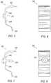
- Figures 2-4illustrate one example of an extruded expandable barrier 200.
- Figure 2is a profile view of extruded expandable barrier 200
- Figure 3is a side view.
- expandable barrier 200is an extrusion having curved flanges 202, 204 at each end, and having one or more protrusions or fingers 210, 212 along an elongated middle section.
- a protrusion, such as protrusion 212may be shaped to interlock with another barrier, or with a cavity area.
- Protrusion 212for example, is generally "T" shaped and configured to interlock with a slot in another barrier, or within a recess in a cavity.
- barrier 200is approximately 135.5 mm in length, and approximately 45.6 mm in width.
- the flexibility of extrusion processesallows a manufacturer to easily change the shape and dimensions of any barrier, including barrier 200.
- barrier 200is an extruded part, it can be cut to almost any desired length, which will generally depend on the particular cavity to be filled by barrier 200.
- barrier 200is cut to a length of approximately 38.1 mm.
- Barrier 200may also include one or more additional components, such as a fastener 220, as shown in Figure 4 .
- Fastener 220is generally a mechanical fastener used to secure barrier 200 within a desired location with a cavity.
- Figures 5-8illustrate another example of an extruded expandable barrier 300.
- Figure 5is a profile view of extruded expandable barrier 300
- Figure 6is a side view.
- Barrier 300is generally "C" shaped with end flanges 302, 304 that can curve and taper off.
- Barrier 300also includes one or more protrusions 306, and includes a slot 310 located approximately mid-way along the length of barrier 300. Slot 310 is configured to interlock or complement a generally "T" shaped protrusion, such as protrusion 212 of barrier 200.
- barrier 300is generally about 46.1 mm in width and 86.6 mm in length, and is cut to a length of 38.1 mm, although barrier 300 can be cut to any length, as previously discussed.
- barrier 300may also include a fastener 320, as shown in Figures 7-8 , to secure barrier 300 in place within a cavity.
- Barrier 300may also be secured in a cavity by relying on the resilient nature of the expandable material formed to shape.
- end flanges 302, 304may be wedged into a groove or corner of a cavity area, securing barrier 300 in place using an interference fit.
- a cavitymay include a protrusion that can mate with slot 320.
- barrier 300may include a slot 310 that is specifically designed to snugly slide over a protrusion formed within a cavity.
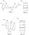
- Figures 9-10illustrate yet another example of an extruded expandable barrier 400, where Figure 9 is a profile view of extruded expandable barrier 400, and Figure 10 is a side view.
- barrier 400includes end flanges 402, 404 that bend, curve, and taper off at their respective end portions.
- Barrier 400also includes one or more fingers or protrusions 606, and includes a slot 410 located approximately mid-way along the length of barrier 400. Slot 410 is also configured to interlock or complement a generally "T" shaped protrusion, such as protrusion 212 of barrier 200.
- barrier 400is generally about 151 mm in length, 72.5 mm in width, and is cut to a length of 38.1 mm, although barrier 400 can be cut to any length, as previously discussed. Like other barriers, barrier 400 may also be secured in a cavity by relying on the resilient nature of the expandable material, or barrier 400 may include one or more fasteners.
- Figures 11-12illustrate yet another example of an extruded expandable barrier 500, where Figure 11 is a profile view of extruded expandable barrier 500, and Figure 12 is a side view.
- barrier 500includes a plurality of fingers or protrusions 506 of various shapes, sizes, and orientations. Barrier 500 may also include a generally "T" shaped protrusion 508 that is configured to interlock or complement a slot, such as slot 410 of barrier 400.
- barrier 500is generally about 80 mm in length, 85.3 mm in width, and is cut to a length of 38.1 mm, although barrier 500 can be cut to any length, as previously discussed.
- barrier 500may also be secured in a cavity by relying on the resilient nature of the expandable material, or barrier 500 may include one or more fasteners.
- Figures 13-14illustrate yet another example of an extruded expandable barrier 600, where Figure 13 is a profile view of extruded expandable barrier 600, and Figure 14 is a side view.
- barrier 600is an oblong shape with a plurality of interior cavities of various shapes and sizes.
- Figure 14is a side view illustrating that barrier 600 can be extruded to substantial lengths, or cut into shorter, individual pieces.
- Figure 15is a profile view of extruded expandable barrier 500 shown in Figure 11
- Figure 16is a profile view of extruded expandable barrier 300 shown in Figure 5
- Figure 17is a side view of extruded expandable barrier 500 shown in Figure 11
- Figure 18is a side view of extruded expandable barrier 300 shown in Figure 5 .
- Figures 19-20illustrate extruded expandable barriers 300, 500 in a pre-expansion state and secured within a cavity.
- barriers 300, 500are secured within their respective cavities using an interference or friction fit, where end flanges and fingers apply pressure to the cavity walls and hold barriers 300, 500 in place.
- Figure 21illustrates an interlocking feature of extruded expandable barriers 300, 500.
- barrier 300may include a slot 310
- barrier 500may include a generally "T" shaped protrusion 508.
- Slot 310 and protrusion 508may be complementary, thereby allowing barriers 300 and 500 to interlock.
- a grouping of barrier partsmay be used in vary large or oddly shaped cavities.
- the interlocking featuremay also facilitate securing the barriers within a cavity.
- the interlocking featuremay also facilitate providing additional expandable material in difficult to reach areas within a cavity, thereby improving the sealing characteristics of the within the cavity after the barriers undergo expansion.
- Figures 22-23illustrate barriers 300, 500 in a post-expansion state within a cavity. As shown, the cavities are completely or substantially filled, thereby creating an efficient barrier against noise, wind, vibration, water, moisture, debris, and other unwanted contaminants.
- Table 1illustrates four different heating profiles labeled Temp 1-4, each of which may also be viewed as a set of extrusion parameters.
- Each heating profile shown in Table 1includes desired temperatures in different parts of system 100, and also includes a particular screw speed shown in RPMs.
- Each profilewas used and tested to form a barrier, such as barrier 500 as shown in Figures 11 and 13 .
- the extrusion processes used to test the various heating profilesused screw R21 without mixing pins, 20 screens, and the expandable material used was SB-300. In order to improve the surface of barrier 500, the RPMs were lowered in order to increase the residence time in the barrel. Based on the desired result, the heating profile shown in the column labeled Temp 4 yielded a preferred surface.
- Table 2represents two additional heating profiles that include various extrusion parameters used to form a barrier, such as barrier 300 as shown in Figures 5 and 14 .
- the RPMswere lowered in order to increase the residence time in the barrel. Based on the desired result, the heating profile shown in the column labeled Temp 2 yielded a preferred surface.
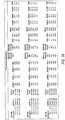
- Figure 24is a table representing shrink results from testing performed on various extruded barriers, illustrating different results using various screw speeds (RPMs), and barrier dimensions. Shrink analysis (100° C (212°F) for 15 minute bake) and a free bake analysis (176,7° C (350° F) for 25 minutes) were performed on samples from each run. The results from the shrink analysis are indicated in Figure 24 , and the results from the free bake analysis (free bake expansion results) are indicated in a table shown in Figure 25 .
- Shrink analysis100° C (212°F) for 15 minute bake
- a free bake analysis176,7° C (350° F) for 25 minutes
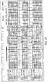
- Figure 26is a table representing various extrusion process testing runs using various extrusion parameters to form barriers of various shapes and sizes, as indicated in Figure 26 .
- the barriers formed from those testing runswere then subjected to shrink test and free bake tests.
- Shrink test analysiswas performed at 100° C (212°F) for a 15 minute bake, and free bake analysis was performed at 176,7° C (350° F) for 25 minutes.
- a sample of the highest speed for the DB-240 and SB-255 materialwas used to bake out in a cavity (176,7° C (350° F) for 25 minutes).
- Figures 27 and 28where Figure 27 is a table representing shrink test results, and Figure 28 is a table representing free bake expansion test results.
- Figures 29-30are tables representing various extrusion process testing runs using various extrusion parameters to form barriers of various shapes and sizes, as indicated in Figure 29 .
- the barriers formed from those testing runswere then subjected to shrink test and free bake tests. Shrink test analysis was performed at 100° C (212°F) for a 15 minute bake, and free bake analysis was performed at 176,7° C (350° F) for 25 minutes. The results from those tests are included in Figures 29-30 .
- the disclosed extrusion processmay use a wide variety of different heating profiles that include a wide range of extrusion parameters to achieve different product results.
- heating temperatures in various areas of extrusion system 100may range from less than 37,8° C (100° F), to well over 93.3° C (200° F), and even more than 121.1° C (250° F).
- screw speedsmay vary from very low RPMs, even less than 20 RPMs, to more than 80 RPMs.
- some extrusion systemsmay measure material speed in feet per minute (FPM) or feet per hour (FPH), as shown in the various tables. Different dies, cooling systems, and other components may also be used and/or changed to produce a desired result.
- barriersmay be cut, trimmed, or drilled or punctured to create holes, notches, or other physical features.
- barriersmay be augmented or one or more mechanical or chemical fasteners, or additional materials.
- a barriermay include structures or features to facilitate the handling or movement of the barrier by robots or structures to facilitate installation.
- a barriermay include a second material as well, such as a pre-activation sealer material.
- a barriermay include a placement area in the form of a ridge on which pre-activation sealer material may be placed.
- other structuresmay be used to accept the sealer material such as ledges, troughs and wells.
- the placement areamay also serve other purposes or functions besides receiving the pre-activation sealer material such as directing the activated sealer material or ensuring that the barrier is properly fit in to the orifice.
- FIG 31illustrates an extruded expandable barrier 700 manufactured utilizing the disclosed extrusion processes.
- Barrier 700is an extrusion having curved flanges 702, 704 at each end of an elongated body 706.
- Barrier 700also includes an integrated tab 710 disposed on body 706.
- tab 706is shaped to be inserted into a slot 810 of a cavity wall 800.
- slot 810is a small slit or elongated oval aperture or hole in cavity wall 800.
- Tab 710is a short strip of expandable material integrally formed with body 706 of barrier 700.
- Tab 710may include one or more ridges 712 that can be used to orient barrier 700 in place, and also releasably secure barrier 700 to cavity wall 800.
- barrier 700can be releasably secured to cavity wall 800 through an interference or friction fit after inserting tab 710 into slot 810. Because tab 710 is integrated into body 706 of barrier 700, no post manufacturing process is required to add any mechanical fastener to barrier 700. Additionally, barrier 700 can be installed with little to no tooling, adhesives, etc. Of course, barrier 700 can be further secured to cavity wall 800 through the use of adhesives or mechanical fasteners.
- Figure 32illustrates another extruded expandable barrier 900, also manufactured utilizing the disclosed extrusion processes.
- Barrier 900is also an extrusion having curved flanges 902, 904 at each end of an elongated body 906.
- Barrier 900includes a fastener 910 disposed through body 906.
- Fastener 910is typically installed after extruding barrier 900 by punching a hole through body 906 and then inserting fastener 910 through that hole.
- Fastener 910can be a nail, a screw, or a flanged fastener made of metal or plastic.
- fastener 910is shaped to be inserted into an aperture 812 of cavity wall 800, thereby securing barrier 900 to cavity wall 800.
- Figure 33illustrates an exemplary process 1000 for sealing a cavity.
- Process 1000begins in step 1010 by identifying a cavity to be sealed.
- a cavity to be sealedtypically, an original equipment manufacturer will identify a particular cavity where sealing the cavity will result in overall decreased noise, vibration, or protect another portion of the product from fumes, dirt, dust, water, etc.
- Identifying the cavitymay also include identifying the dimensions of the portion of the cavity to be sealed. For example, the dimensions can be obtained using engineering drawings or by measuring the interior space of the cavity, such as by measuring a cross-section of the cavity at a particular location.
- an expandable materialwill be selected.
- selecting a particular expandable materialmay depend on a particular set of requirements from a customer, such as an original equipment manufacturer. Additionally, the particular expandable material may depend on the overall size of the cavity to be sealed.
- an extrusion profilewill be designed.
- the extrusion profileis designed to strategically place the expandable material throughout the cavity.
- the portions of the barriersuch as flanges and protrusions, will distribute the expandable material within the cavity in such a way as to ensure that the expandable material fills and seals the cavity after undergoing expansion.
- an extrusion profilemay include any design capable of being used in conjunction with the disclosed extrusion processes.
- an extrusion profilemay include en elongated section to span a substantial lateral portion of a cavity.
- an extrusion profilemay include curved end flanges, a tab, and one or more protrusion.
- An extrusion profilecan be planar or substantially flat, curved, "C” shaped, “S” shaped, “U” shaped, “O” shaped, donut shaped, or any other suitable shape that can be used with the extrusion process and used to strategically place expandable material in the cavity.
- the extrusion profilemay also include an interlocking or mating feature, such as a slot or "T" shaped protrusion, allowing two or more extruded barriers to be mechanically linked together through an interference fit, as previously described.
- a cut lengthmay also be selected in conjunction with the design of the extrusion profile. For example, an estimate of an amount of expandable material may be generated based on the size of the cavity to be sealed and the expansion properties of the selected expandable material.
- the volume per barriercan be calculated using a cut length and the extrusion profile design.
- the profiler design, i.e. shaped cut-out, of the extrusion profileprovides an area that can be multiplied by the cut length of the extruded barrier to provide a close approximation of the volume of expandable material per part.
- a heating profileis developed.
- a heating profilemay be developed through testing of a particular expandable material. Further, a heating profile may be developed by using an existing heating profile with the newly designed extrusion profile, and testing the extruded barriers for various parameters, such as shrinkage and expansion.
- a heating profilemay include any number of heating and other parameters, such as screw speed, material feed rate, pressure, etc.
- a heating profilemay also be adjusted after testing the seal of the post-expansion barriers in the cavities.
- a profileris made in the shape of the selected extrusion profile.
- the profilerbeing a removable plate, a series of screens, or some other extrusion profile system.
- the profileis then typically installed in extrusion system 100.
- step 1060a barrier is extruded using system 100.
- system 100is configured to use the selected heating profile and the extrusion profile to make the designed extruded barriers.
- a mechanical fastenermay be added to the extruded barrier.
- the barrieris installed into a cavity.
- the barriermay be secured or releasably secured within the cavity in any number of ways.
- the barriermay include protrusions or flanges designed to be wedged into a weld seam within the cavity.
- the barriermay include a tab or fastener configured to mate with a corresponding slot or aperture in a cavity wall.
- a barriermay be secured in place using an adhesive, a rigid carrier, etc.
- step 1090the barrier undergoes an activation process. If the barrier is made using a heat activated expandable material, the cavity may undergo a baking process to evenly heat the cavity and barrier and thereby activate the expandable material. After undergoing an activation process, the barrier expands to fill and seal the cavity. Following step 1090, the particular seal may be tested, measured, and the process may be further refined by redesigning the extrusion profile and/or the heating profile.
Landscapes
- Engineering & Computer Science (AREA)
- Mechanical Engineering (AREA)
- Physics & Mathematics (AREA)
- Thermal Sciences (AREA)
- Chemical & Material Sciences (AREA)
- Combustion & Propulsion (AREA)
- Transportation (AREA)
- Architecture (AREA)
- Structural Engineering (AREA)
- Extrusion Moulding Of Plastics Or The Like (AREA)
Description
- This application claims the benefit of
U.S. Provisional Patent Application Serial No. 61/021,563, filed on January 16, 2008 - Barriers are commonly used to seal orifices in certain objects. For example, barriers are commonly used in various parts of a motor vehicle to prevent noise, fumes, dirt, water, and the like from passing through from one area to another. A motor vehicle door panel typically has several small orifices in the sheet metal for manufacturing, assembly, and weight reduction reasons. Further, various structural components of motor vehicle bodies typically include a variety of orifices, hollow posts, cavities, passages and openings that could allow contaminants from the engine and the roadway into the passenger compartment.
US 3956438 discloses a process for extruding a partially foamed thermoplastic product, wherein the product is foamed in the extruder.EP 1790554 A1 discloses the preamble ofclaim 1, an expandable material and fastenable member for sealing, baffling or reinforcing and a method of forming the same. Figure 1 illustrates an exemplary extrusion system.Figure 2 is a profile view of one example of an extruded expandable barrier.Figure 3 is a side view of the extruded expandable barrier shown inFigure 2 .Figure 4 is a profile view of the extruded expandable barrier shown inFigure 2 with a fastener.Figure 5 is a profile view of another example of an extruded expandable barrier.Figure 6 is a side view of the extruded expandable barrier shown inFigure 5 .Figure 7 is a profile view of the extruded expandable barrier shown inFigure 5 with a fastener.Figure 8 is a side view of the extruded expandable barrier shown inFigure 5 with a fastener.Figure 9 is a profile view of another example of an extruded expandable barrier.Figure 10 is a side view of the extruded expandable barrier shown inFigure 9 .Figure 11 is a profile view of another example of an extruded expandable barrier.Figure 12 is a side view of the extruded expandable barrier shown inFigure 11 .Figure 13 is a profile view of another example of an extruded expandable barrier.Figure 14 is a side view of the extruded expandable barrier shown inFigure 13 .Figure 15 is a profile view of the extruded expandable barrier shown inFigure 11 .Figure 16 is a profile view of the extruded expandable barrier shown inFigure 5 .Figure 17 is a side view of the extruded expandable barrier shown inFigure 11 .Figure 18 is a side view of the extruded expandable barrier shown inFigure 5 .Figures 19-20 illustrate the extruded expandable barriers shown inFigures 5 &11 in a pre-expansion state and secured within a cavity.Figure 21 illustrates an interlocking feature of the extruded expandable barriers shown inFigures 5 &11 .Figures 22-23 illustrate the extruded expandable barriers shown inFigures 5 &11 in a post-expansion state within a cavity.Figure 24 is a table representing shrink test results, and illustrating different results using various screw speeds (RPMs), and barrier dimensions.Figure 25 is a table representing free bake expansion results.Figure 26 is a table representing various extrusion process testing runs using various extrusion parameters to form barriers of various shapes and sizes.Figure 27 is a table representing shrink test results.Figure 28 is a table representing free bake expansion test results.Figure 29 is another table representing various extrusion process testing runs using various extrusion parameters to form barriers of various shapes and sizes.Figure 30 is another table representing various extrusion process testing runs using various extrusion parameters to form barriers of various shapes and sizes.Figure 31 is a perspective view of an extruded expandable barrier having an integrated tab configured to releasably secure to a side wall of a cavity.Figure 32 is a perspective view of another extruded expandable barrier having a fastener configured to releasably secure to a side wall of a cavity.Figure 33 illustrates an exemplary process for sealing a cavity.- Expandable barriers are typically barriers made from an expandable material and formed to fit within a cavity. After being placed inside a cavity, expandable barriers generally undergo an activation process, where the expandable barrier expands to fill the cavity and create a physical barrier. Many expandable barriers are developed using injection molding processes, such as 2-shot or over-molding. However, such injection molting processes are costly, time-consuming, and inflexible. For example, any design change typically requires expensive tooling changes and may require new tooling all together. Thus, in injection molding processes, it is very difficult and often expensive to make even minor design changes.
- Disclosed are various embodiments of an extruded expandable barrier, and various processes and systems for manufacturing the same utilizing extrusion processes. Using various extrusion processes to form an expandable barrier allows for a reduction in tooling costs, while also allowing more flexible barrier designs. Such designs can be specifically tailored for a particular cavity or cavities to ensure that the barrier fills the cavity after expansion. In addition, design changes can occur with little to no tooling changes. For example, using an extrusion system allows for easily modifying a barrier with minimal time, effort, and tooling costs. Through the disclosed processes and systems, a barrier can easily be modified by adding, removing, or changing the length, shape, protrusions, fingers, ribs, etc.
- Using the disclosed extrusion processes, the cut length of expandable barriers can be easily changed, thereby changing the amount of expandable material that is in a cavity. Such a process offers easy adjustment to the parts with little to no tooling costs. Further, the disclosed extrusion processes provide a very consistent part performance because it puts low amounts of stress into the material of the barrier part. It accomplishes this by keeping the shear stress in the material low during the manufacturing process. In addition, the disclosed extrusion processes can reduce vehicle complexity by allowing the same barrier part design to be used for both sides of the vehicle, thus cutting barrier part numbers in half.
- Such extruded barrier parts can be attached to a vehicle by adding a fastener, capturing the barrier part in weld seams, adding tabs to the sheet metal, or designing an integrated fastener that is extruded in the part design that will attach to the sheet metal. Further, such extruded barriers can be designed with or without an additional material for a carrier. Extruded barriers can be co-extruded or in-line extruded with other materials to provide multiple expansion results as well. In addition, extruded barriers can be extruded flat and die cut to shape if required.
- Various additional processes can also be utilized to create more complex extruded barriers. For example, some processes can also utilize die cutting for more complex cavities so that extruded barriers can fit into a cavity properly, or even to allow tubes to be installed prior to bake out, such as drain tubes. This will allow 100% sealing around the drain tube.
- The disclosed extrusion processes can create flat or profile extruded expandable barriers for various cavities. Generally, a thermoplastic expandable material is used to create such extruded expandable barriers. Thermoplastic expandable materials are generally materials that soften when heated and harden when cooled, and expands upon activation. Generally, such materials are activated using heat, although an expandable material may be activated by a chemical reaction, radiation exposure, microwave exposure, electricity, etc. One example of a suitable expandable material is a heat activated material. For example, the Sika Corporation of Madison Heights, Michigan, sells such thermoplastic expandable materials under the SIKABAFFLE trade name, which are described in the following U.S. Patents, all of which are incorporated herein by reference in their entireties:
U.S. Patent Nos. 5,266,133 ;5,373,027 ;6,150,428 ;6,368,438 ; and6,387,470 . Other examples of materials that can be used are also provided by the Sika Corporation are SB-240, SB-255, SB-300, and SB-751. Other materials that are capable of undergoing the described extrusion process can also be used, including those that can expand from less than 100% to over 2000%. Figure 1 illustrates one example of anextrusion system 100 for manufacturing extruded expandable barriers.System 100 includes ahopper 102, abarrel 106, anextrusion screw 108, ascrew drive motor 110, and adie 120. Typically, an expandable material is provided in a solid or a liquid form. For example, one of the above mentioned SIKABAFFLE expandable materials may be provided in solid form, such as in pellets, and placed inhopper 102. The expandable material may be gravity fed intobarrel 106, where heat is applied to the material to make it more pliable. The expandable material leaveshopper 102 and entersbarrel 106 through afeedthroat 104, which is typically an opening near the rear ofbarrel 106, where the expandable material comes into contact withextrusion screw 108. Generally,system 100 uses a combination of heating elements and shear heating fromextrusion screw 108 to apply heat to the expandable material insidebarrel 106.Extrusion screw 108, which is driven by ascrew drive motor 128, rotates and forces the expandable material throughdie 120 in order to form the expandable material into a desired shape, thereby forming an extruded barrier.Die 120 may also include aprofiler 122.Profiler 122 is typically a removable plate with a shaped opening that can be used in conjunction withdie 120 to form the expandable material into a desired shape.Profiler 122 may also be a screen or some other removable component used to further shape the expandable material into a barrier. The expandable material can be cooled to cause it to solidify into a more solid and less pliable state as it is pulled through die 120, or after leavingdie 120.- A heating profile may be used and altered based on various factors, such as the type of material and the desired dimensions of extruded barrier. A heating profile is generally a pre-determined set of heating parameters that control one or more temperature devices in an extrusion system, such as
system 100. A heating profile may be set forbarrel 106 in which three or more independently controlled heaters gradually increase the temperature ofbarrel 106 from the rear (where the plastic enters at feedthroat 104) to the front atdie 120. This allows the expandable material to be heated gradually as the material is pushed throughbarrel 106, thereby lowering the risk of overheating. Extra heat is contributed by the intense pressure and friction taking place insidebarrel 106. Cooling fans, water lines, or other cooling devices may also be used to ensure that the temperature is maintained below a pre-set limit.System 100 may also include any number and variety of additional components, including one or more controllers, computers, microcontrollers, temperature sensors, pressure sensors, speed sensors, and feedback control systems to change one or more operating parameters based on the output from one or more sensors. - Generally, the temperature, or heating profile, is based on various factors, including the material parameters. Because many expandable materials are heat activated, the temperature of the material is generally maintained below the expandable material's specific activation temperature to prevent premature expansion. When using SIKABAFFLE expandable materials, for example, the temperature is generally kept below 176,7° C (350° F) and for some materials, may need to be kept below 121,1° C (250° F). Generally, the precise temperature may need to be established through various trials to compensate for differences in expandable material properties, extrusion systems, and extruded barrier designs. Furthermore, as will be described in greater detail below, additional parameters may be modified to produce different results. For example,
system 100 may utilize different dies, profilers, barrels, and types of screws. For example, various types of screws may use optional components, such as mixing pins or the like. Furthermore,system 100 may utilize different heating profiles, screw speeds (generally in rotations per minute (RPM)), barrel pressures, die pressures, different dies, profilers, or any other parameter or component. - Generally, the expandable material is forced through
die 120 and out ofprofiler 122.Die 120 andprofiler 122 give the final expandable barrier product its profile shape. A profile shape is generally designed to ensure that the expandable barrier can fit within a particular cavity, and also create a desired physical barrier after undergoing an expansion process. Typically, the expandable barrier's size and shape are generally dictated by the size and shape of the cavity or orifice into which the barrier is to be inserted.Figures 2-12 illustrate several examples of potential shapes and configurations of extruded expandable barriers, but are by no way an exhaustive or exclusive representation of the various shapes and configurations of barriers that are capable of being formed using the disclosed extrusion process. Figures 2-4 illustrate one example of an extrudedexpandable barrier 200.Figure 2 is a profile view of extrudedexpandable barrier 200, andFigure 3 is a side view. As shown inFigure 2 ,expandable barrier 200 is an extrusion havingcurved flanges fingers protrusion 212, may be shaped to interlock with another barrier, or with a cavity area.Protrusion 212, for example, is generally "T" shaped and configured to interlock with a slot in another barrier, or within a recess in a cavity. As shown,barrier 200 is approximately 135.5 mm in length, and approximately 45.6 mm in width. The flexibility of extrusion processes allows a manufacturer to easily change the shape and dimensions of any barrier, includingbarrier 200. In addition, becausebarrier 200 is an extruded part, it can be cut to almost any desired length, which will generally depend on the particular cavity to be filled bybarrier 200. As shown inFigure 3 ,barrier 200 is cut to a length of approximately 38.1 mm.Barrier 200 may also include one or more additional components, such as afastener 220, as shown inFigure 4 .Fastener 220 is generally a mechanical fastener used to securebarrier 200 within a desired location with a cavity.Figures 5-8 illustrate another example of an extrudedexpandable barrier 300.Figure 5 is a profile view of extrudedexpandable barrier 300, andFigure 6 is a side view.Barrier 300 is generally "C" shaped withend flanges Barrier 300 also includes one ormore protrusions 306, and includes aslot 310 located approximately mid-way along the length ofbarrier 300.Slot 310 is configured to interlock or complement a generally "T" shaped protrusion, such asprotrusion 212 ofbarrier 200. As shown inFigures 5-8 ,barrier 300 is generally about 46.1 mm in width and 86.6 mm in length, and is cut to a length of 38.1 mm, althoughbarrier 300 can be cut to any length, as previously discussed. Furthermore, as previously discussed,barrier 300 may also include afastener 320, as shown inFigures 7-8 , to securebarrier 300 in place within a cavity.Barrier 300, as well as many other designs of an extruded expandable barrier, may also be secured in a cavity by relying on the resilient nature of the expandable material formed to shape. For example, endflanges barrier 300 in place using an interference fit. In addition, a cavity may include a protrusion that can mate withslot 320. For example,barrier 300 may include aslot 310 that is specifically designed to snugly slide over a protrusion formed within a cavity.Figures 9-10 illustrate yet another example of an extrudedexpandable barrier 400, whereFigure 9 is a profile view of extrudedexpandable barrier 400, andFigure 10 is a side view. As shown inFigure 9 ,barrier 400 includesend flanges Barrier 400 also includes one or more fingers or protrusions 606, and includes aslot 410 located approximately mid-way along the length ofbarrier 400.Slot 410 is also configured to interlock or complement a generally "T" shaped protrusion, such asprotrusion 212 ofbarrier 200. As shown inFigures 9-10 ,barrier 400 is generally about 151 mm in length, 72.5 mm in width, and is cut to a length of 38.1 mm, althoughbarrier 400 can be cut to any length, as previously discussed. Like other barriers,barrier 400 may also be secured in a cavity by relying on the resilient nature of the expandable material, orbarrier 400 may include one or more fasteners.Figures 11-12 illustrate yet another example of an extrudedexpandable barrier 500, whereFigure 11 is a profile view of extrudedexpandable barrier 500, andFigure 12 is a side view. As shown inFigure 11 ,barrier 500 includes a plurality of fingers orprotrusions 506 of various shapes, sizes, and orientations.Barrier 500 may also include a generally "T" shapedprotrusion 508 that is configured to interlock or complement a slot, such asslot 410 ofbarrier 400. As shown inFigures 11-12 ,barrier 500 is generally about 80 mm in length, 85.3 mm in width, and is cut to a length of 38.1 mm, althoughbarrier 500 can be cut to any length, as previously discussed. Like other barriers,barrier 500 may also be secured in a cavity by relying on the resilient nature of the expandable material, orbarrier 500 may include one or more fasteners.Figures 13-14 illustrate yet another example of an extrudedexpandable barrier 600, whereFigure 13 is a profile view of extrudedexpandable barrier 600, andFigure 14 is a side view. As shown,barrier 600 is an oblong shape with a plurality of interior cavities of various shapes and sizes.Figure 14 is a side view illustrating thatbarrier 600 can be extruded to substantial lengths, or cut into shorter, individual pieces.Figure 15 is a profile view of extrudedexpandable barrier 500 shown inFigure 11 , andFigure 16 is a profile view of extrudedexpandable barrier 300 shown inFigure 5 .Figure 17 is a side view of extrudedexpandable barrier 500 shown inFigure 11 , andFigure 18 is a side view of extrudedexpandable barrier 300 shown inFigure 5 .Figures 19-20 illustrate extrudedexpandable barriers Figures 19-20 ,barriers barriers Figure 21 illustrates an interlocking feature of extrudedexpandable barriers barrier 300 may include aslot 310, andbarrier 500 may include a generally "T" shapedprotrusion 508.Slot 310 andprotrusion 508 may be complementary, thereby allowingbarriers Figures 22-23 illustratebarriers - Table 1 illustrates four different heating profiles labeled Temp 1-4, each of which may also be viewed as a set of extrusion parameters. Each heating profile shown in Table 1 includes desired temperatures in different parts of
system 100, and also includes a particular screw speed shown in RPMs. Each profile was used and tested to form a barrier, such asbarrier 500 as shown inFigures 11 and13 . The extrusion processes used to test the various heating profiles used screw R21 without mixing pins, 20 screens, and the expandable material used was SB-300. In order to improve the surface ofbarrier 500, the RPMs were lowered in order to increase the residence time in the barrel. Based on the desired result, the heating profile shown in the column labeledTemp 4 yielded a preferred surface. All temperatures are in degrees Celsius (degrees Fahrenheit), and RPMs are measured in rotations per minute, which correspond to the screw speed.Table 1 Temp 1Temp 2Temp 3Temp 4Die 104.4 (220) 104.4 (220) 107.2 (225) 112.8 (235) Gate 97.2 (207) 104.4 (220) 107.2 (225) 112.8 (235) bzone 4 93.3 (200) 98.9 (210) 112.2 (234) 121.1 (250) bzone 3 90 (194) 93.3 (200) 104.4 (220) 118.3 (245) bzone 2 82.2 (180) 82.2 (180) 85 (185) 87.8 (190) bzone 1 73.9 (165) 73.9 (165) 73.9 (165) 73.9 (165) RPM 60 60 60 42.8 - Table 2 represents two additional heating profiles that include various extrusion parameters used to form a barrier, such as
barrier 300 as shown inFigures 5 and14 . The extrusion process used to test the various heating profiles screw R21 without mixing pins, 20-40 screens, and the expandable material used was also SB-300. In order to improve the surface ofbarrier 300, the RPMs were lowered in order to increase the residence time in the barrel. Based on the desired result, the heating profile shown in the column labeledTemp 2 yielded a preferred surface.Table 2 Temp 1Temp 2Die 112.8 (235) 104.4 (220) Gate 112.8 (235) 104.4 (220) bzone 4 121.1 (250) 114.4 (238) bzone 3 118.3 (245) 115 (239) bzone 2 87.8 (190) 87.8 (190) bzone 1 73.9 (165) 73.9 (165) RPM 49 60 Figure 24 is a table representing shrink results from testing performed on various extruded barriers, illustrating different results using various screw speeds (RPMs), and barrier dimensions. Shrink analysis (100° C (212°F) for 15 minute bake) and a free bake analysis (176,7° C (350° F) for 25 minutes) were performed on samples from each run. The results from the shrink analysis are indicated inFigure 24 , and the results from the free bake analysis (free bake expansion results) are indicated in a table shown inFigure 25 .Figure 26 is a table representing various extrusion process testing runs using various extrusion parameters to form barriers of various shapes and sizes, as indicated inFigure 26 . The barriers formed from those testing runs were then subjected to shrink test and free bake tests. Shrink test analysis was performed at 100° C (212°F) for a 15 minute bake, and free bake analysis was performed at 176,7° C (350° F) for 25 minutes. After evaluating the shrink test and free bake results, a sample of the highest speed for the DB-240 and SB-255 material was used to bake out in a cavity (176,7° C (350° F) for 25 minutes). The results from those tests are illustrated inFigures 27 and28 , whereFigure 27 is a table representing shrink test results, andFigure 28 is a table representing free bake expansion test results.Figures 29-30 are tables representing various extrusion process testing runs using various extrusion parameters to form barriers of various shapes and sizes, as indicated inFigure 29 . The barriers formed from those testing runs were then subjected to shrink test and free bake tests. Shrink test analysis was performed at 100° C (212°F) for a 15 minute bake, and free bake analysis was performed at 176,7° C (350° F) for 25 minutes. The results from those tests are included inFigures 29-30 .- As illustrated in Tables 1-2 and in
Figures 24-30 , the disclosed extrusion process may use a wide variety of different heating profiles that include a wide range of extrusion parameters to achieve different product results. For example, heating temperatures in various areas ofextrusion system 100 may range from less than 37,8° C (100° F), to well over 93.3° C (200° F), and even more than 121.1° C (250° F). Furthermore, screw speeds may vary from very low RPMs, even less than 20 RPMs, to more than 80 RPMs. In addition, some extrusion systems may measure material speed in feet per minute (FPM) or feet per hour (FPH), as shown in the various tables. Different dies, cooling systems, and other components may also be used and/or changed to produce a desired result. - As previously discussed, an infinite number other variations of the illustrated preferred embodiments are contemplated to be include in the scope of the following claims. For example, while several specific examples of barriers are shown, the disclosed extrusion process is capable of being used to form barriers of various shapes, sizes, and configurations. Furthermore, various post-extrusion processes may also be used to further configure a barrier. For example, barriers may be cut, trimmed, or drilled or punctured to create holes, notches, or other physical features. In addition, barriers may be augmented or one or more mechanical or chemical fasteners, or additional materials. A barrier may include structures or features to facilitate the handling or movement of the barrier by robots or structures to facilitate installation.
- A barrier may include a second material as well, such as a pre-activation sealer material. A barrier may include a placement area in the form of a ridge on which pre-activation sealer material may be placed. In addition, other structures may be used to accept the sealer material such as ledges, troughs and wells. The placement area may also serve other purposes or functions besides receiving the pre-activation sealer material such as directing the activated sealer material or ensuring that the barrier is properly fit in to the orifice.
Figure 31 illustrates an extrudedexpandable barrier 700 manufactured utilizing the disclosed extrusion processes.Barrier 700 is an extrusion havingcurved flanges elongated body 706.Barrier 700 also includes anintegrated tab 710 disposed onbody 706. As illustrated inFigure 31 ,tab 706 is shaped to be inserted into aslot 810 of acavity wall 800. Generally,slot 810 is a small slit or elongated oval aperture or hole incavity wall 800.Tab 710 is a short strip of expandable material integrally formed withbody 706 ofbarrier 700.Tab 710 may include one ormore ridges 712 that can be used to orientbarrier 700 in place, and also releasablysecure barrier 700 tocavity wall 800. For example,barrier 700 can be releasably secured tocavity wall 800 through an interference or friction fit after insertingtab 710 intoslot 810. Becausetab 710 is integrated intobody 706 ofbarrier 700, no post manufacturing process is required to add any mechanical fastener tobarrier 700. Additionally,barrier 700 can be installed with little to no tooling, adhesives, etc. Of course,barrier 700 can be further secured tocavity wall 800 through the use of adhesives or mechanical fasteners.Figure 32 illustrates another extrudedexpandable barrier 900, also manufactured utilizing the disclosed extrusion processes.Barrier 900 is also an extrusion havingcurved flanges elongated body 906.Barrier 900 includes afastener 910 disposed throughbody 906.Fastener 910 is typically installed after extrudingbarrier 900 by punching a hole throughbody 906 and then insertingfastener 910 through that hole.Fastener 910 can be a nail, a screw, or a flanged fastener made of metal or plastic. Generally,fastener 910 is shaped to be inserted into anaperture 812 ofcavity wall 800, thereby securingbarrier 900 tocavity wall 800.Figure 33 illustrates anexemplary process 1000 for sealing a cavity.Process 1000 begins instep 1010 by identifying a cavity to be sealed. Typically, an original equipment manufacturer will identify a particular cavity where sealing the cavity will result in overall decreased noise, vibration, or protect another portion of the product from fumes, dirt, dust, water, etc. Identifying the cavity may also include identifying the dimensions of the portion of the cavity to be sealed. For example, the dimensions can be obtained using engineering drawings or by measuring the interior space of the cavity, such as by measuring a cross-section of the cavity at a particular location.- Next, in
step 1020, an expandable material will be selected. Typically, selecting a particular expandable material may depend on a particular set of requirements from a customer, such as an original equipment manufacturer. Additionally, the particular expandable material may depend on the overall size of the cavity to be sealed. - Next, in
step 1030, an extrusion profile will be designed. Typically, the extrusion profile is designed to strategically place the expandable material throughout the cavity. Generally, the portions of the barrier, such as flanges and protrusions, will distribute the expandable material within the cavity in such a way as to ensure that the expandable material fills and seals the cavity after undergoing expansion. As previously discussed, an extrusion profile may include any design capable of being used in conjunction with the disclosed extrusion processes. For example, an extrusion profile may include en elongated section to span a substantial lateral portion of a cavity. Further, an extrusion profile may include curved end flanges, a tab, and one or more protrusion. An extrusion profile can be planar or substantially flat, curved, "C" shaped, "S" shaped, "U" shaped, "O" shaped, donut shaped, or any other suitable shape that can be used with the extrusion process and used to strategically place expandable material in the cavity. In addition, the extrusion profile may also include an interlocking or mating feature, such as a slot or "T" shaped protrusion, allowing two or more extruded barriers to be mechanically linked together through an interference fit, as previously described. - In addition, a cut length may also be selected in conjunction with the design of the extrusion profile. For example, an estimate of an amount of expandable material may be generated based on the size of the cavity to be sealed and the expansion properties of the selected expandable material. The volume per barrier can be calculated using a cut length and the extrusion profile design. The profiler design, i.e. shaped cut-out, of the extrusion profile provides an area that can be multiplied by the cut length of the extruded barrier to provide a close approximation of the volume of expandable material per part.
- Next, in
step 1040, a heating profile is developed. A heating profile may be developed through testing of a particular expandable material. Further, a heating profile may be developed by using an existing heating profile with the newly designed extrusion profile, and testing the extruded barriers for various parameters, such as shrinkage and expansion. A heating profile may include any number of heating and other parameters, such as screw speed, material feed rate, pressure, etc. A heating profile may also be adjusted after testing the seal of the post-expansion barriers in the cavities. - Next, in
step 1050, a profiler is made in the shape of the selected extrusion profile. The profiler being a removable plate, a series of screens, or some other extrusion profile system. The profile is then typically installed inextrusion system 100. - Next, in step 1060, a barrier is extruded using
system 100. Typically,system 100 is configured to use the selected heating profile and the extrusion profile to make the designed extruded barriers. - Next, in
step 1070, a mechanical fastener may be added to the extruded barrier. - Next, in
step 1080, the barrier is installed into a cavity. As previously discussed, the barrier may be secured or releasably secured within the cavity in any number of ways. For example, the barrier may include protrusions or flanges designed to be wedged into a weld seam within the cavity. The barrier may include a tab or fastener configured to mate with a corresponding slot or aperture in a cavity wall. Further, a barrier may be secured in place using an adhesive, a rigid carrier, etc. - Next, in
step 1090, the barrier undergoes an activation process. If the barrier is made using a heat activated expandable material, the cavity may undergo a baking process to evenly heat the cavity and barrier and thereby activate the expandable material. After undergoing an activation process, the barrier expands to fill and seal the cavity. Followingstep 1090, the particular seal may be tested, measured, and the process may be further refined by redesigning the extrusion profile and/or the heating profile.
Claims (8)
- A system (100), comprising:a barrel (106) having a material inlet port (104) disposed proximate to a first end and configured to receive an expandable material through the material inlet port (104), wherein the expandable material is a heat activated expandable material;a die (120) disposed proximate to a second end of the barrel (106), the die (120) including a first opening to receive the expandable material from the barrel (106) and a second opening;a screw (108) substantially disposed within the barrel (106) and configured move the expandable material through the barrel (106) from the inlet port (104) to the die (120),characterized in further comprising:a profiler (122) disposed adjacent to the die (120) at the second opening, wherein the profiler (122) includes a shaped cut-out configured to extrude the expandable material into a formed extruded expandable barrier, wherein the profiler (122) is at least one of a removable plate and a removable screen;a controller configured to implement a heating profile; anda plurality individual temperature controlled zones, wherein the controller is configured to regulate each temperature controlled zone according to the heating profile.
- The system (100) of claim 1, wherein the barrel includes at least two temperature controlled zones, and the die includes at least one temperature controlled zone.
- The system (100) of claim 2, wherein the heating profile is configured to increase the temperature of the expandable material as the expandable material travels through the barrel (106) from the inlet port (104) to the die (120), the heating profile being further configured to maintain each temperature controlled zone at a temperature below 121.11 degrees Celsius.
- The system (100) of claim 1, further comprising a plurality of heating elements selectively controlled via the controller according to the heating profile.
- A method, comprising:identifying a cavity to be sealed;designing an extrusion profile;developing a heating profile;manufacturing a profiler (122) according to the extrusion profile;extruding an expandable material using an extrusion system (100), wherein the expandable material is a heat activated expandable material, the extrusion system (100) being based in part on the heating profile, and the expandable material being extruded through the profiler (122), wherein the profiler (122) is at least one of a removable plate and a removable screen;regulating a plurality of temperature controlled zones according to the heating profile; andcutting the extruded expandable material after being extruded through the profiler (122) to form an extruded expandable barrier configured to seal the identified cavity.
- The method of claim 5, further comprising co-extruding a non-expandable material with the expandable material.
- The method of claim 5, further comprising:
maintaining each temperature controlled zone at a temperature at or below 121.11 degrees Celsius. - The method of claim 5, further comprising increasing the temperature of the expandable material as the expandable material travels through a barrel (106) of the extrusion system (100).
Applications Claiming Priority (2)
| Application Number | Priority Date | Filing Date | Title |
|---|---|---|---|
| US2156308P | 2008-01-16 | 2008-01-16 | |
| PCT/US2009/031216WO2009091953A2 (en) | 2008-01-16 | 2009-01-16 | Extruded expandable barrier |
Publications (2)
| Publication Number | Publication Date |
|---|---|
| EP2242634A2 EP2242634A2 (en) | 2010-10-27 |
| EP2242634B1true EP2242634B1 (en) | 2020-03-25 |
Family
ID=40757016
Family Applications (1)
| Application Number | Title | Priority Date | Filing Date |
|---|---|---|---|
| EP09702098.6AActiveEP2242634B1 (en) | 2008-01-16 | 2009-01-16 | System and method for producing an extruded expandable barrier |
Country Status (3)
| Country | Link |
|---|---|
| US (1) | US9796118B2 (en) |
| EP (1) | EP2242634B1 (en) |
| WO (1) | WO2009091953A2 (en) |
Families Citing this family (9)
| Publication number | Priority date | Publication date | Assignee | Title |
|---|---|---|---|---|
| EP2648882A1 (en) | 2010-12-08 | 2013-10-16 | Zephyros Inc. | Sealing assembly |
| GB201102035D0 (en) | 2011-02-04 | 2011-03-23 | Zephyros Inc | Improvements in or relating to extrusion |
| WO2012174504A2 (en) | 2011-06-17 | 2012-12-20 | Zephyros, Inc. | Cavity sealing assembly |
| MX2013012399A (en) | 2011-06-21 | 2014-02-17 | Zephyros Inc | Integrated fastening system for an expandable sealing device. |
| CA2867929A1 (en) | 2012-03-20 | 2013-09-26 | Zephyros, Inc. | Baffle assembly |
| GB201207481D0 (en) | 2012-04-26 | 2012-06-13 | Zephyros Inc | Applying flowable materials to synthetic substrates |
| KR20150021927A (en) | 2012-06-08 | 2015-03-03 | 제피로스, 인크. | Baffle with expanding material |
| WO2016176459A1 (en) | 2015-04-30 | 2016-11-03 | Zephyros, Inc. | Members for sealing, baffling, or reinforcing |
| CN110730745A (en) | 2017-06-02 | 2020-01-24 | 泽菲罗斯有限公司 | Anti-vibration baffle |
Citations (14)
| Publication number | Priority date | Publication date | Assignee | Title |
|---|---|---|---|---|
| US3956438A (en) | 1971-02-25 | 1976-05-11 | Barmag Barmer Maschinenfabrik Aktiengesellschaft | Process for extruding a partially foamed thermoplastic product |
| US4365946A (en) | 1980-02-01 | 1982-12-28 | Hermann Berstorff Maschinenbau Gmbh | Apparatus for continuously processing rubber, elastomers, plastics and like materials which can be vulcanized or cross-linked |
| US4612355A (en) | 1983-10-04 | 1986-09-16 | Rb Kunststoffpatent- Verwertungs Ag | Process for the performance of chemical reactions, more particularly for the manufacture of plastics by means of extruders and apparatus for the process |
| US5160465A (en) | 1989-02-13 | 1992-11-03 | Exxon Chemical Patents Inc. | Process of insulating a body cavity |
| US5358397A (en) | 1993-05-10 | 1994-10-25 | L&L Products, Inc. | Apparatus for extruding flowable materials |
| US5385951A (en) | 1990-08-08 | 1995-01-31 | Exxon Chemical Patents Inc. | Processes for producing foamable parts |
| US5424023A (en) | 1993-06-03 | 1995-06-13 | Crane Plastics Company Limited Partnership | Apparatus and method of forming curved extruded products |
| US5458824A (en) | 1992-04-23 | 1995-10-17 | The Geauga Company | Method of manufacturing a rubber/plastic co-extrudate |
| US5738935A (en) | 1993-08-30 | 1998-04-14 | Formtech Enterprises, Inc. | Process to make a composite of controllable porosity |
| US6000926A (en) | 1996-10-22 | 1999-12-14 | Schirmer; Henry G. | Modular disk coextrusion die |
| EP1331080A2 (en) | 2002-01-25 | 2003-07-30 | L & L Products Inc. | Method and apparatus for applying flowable materials like polyurethane or epoxy resin after pretreating the surface with plasma or primer |
| US6830799B1 (en) | 1999-10-26 | 2004-12-14 | Orbseal Llc | Expandable compositions and methods of making and using the compositions |
| WO2005002950A2 (en) | 2003-06-26 | 2005-01-13 | L & L Products, Inc. | Expandable material and fastenable member for sealing, baffling or reinforcing and method of forming same |
| WO2008065049A1 (en) | 2006-11-27 | 2008-06-05 | Henkel Ag & Co. Kgaa | Expandable filler insert and methods of producing the expandable filler insert |
Family Cites Families (5)
| Publication number | Priority date | Publication date | Assignee | Title |
|---|---|---|---|---|
| US3954366A (en)* | 1975-01-06 | 1976-05-04 | Fields Reuben T | Two-stage single screw extrusion apparatus |
| US5266133A (en) | 1993-02-17 | 1993-11-30 | Sika Corporation | Dry expansible sealant and baffle composition and product |
| US6387470B1 (en) | 1998-11-05 | 2002-05-14 | Sika Corporation | Sound deadening and structural reinforcement compositions and methods of using the same |
| US6150428A (en) | 1999-09-28 | 2000-11-21 | Sika Corporation | Expansion temperature tolerant dry expandable sealant and baffle product and method of preparing same |
| US7249415B2 (en)* | 2003-06-26 | 2007-07-31 | Zephyros, Inc. | Method of forming members for sealing or baffling |
- 2009
- 2009-01-16EPEP09702098.6Apatent/EP2242634B1/enactiveActive
- 2009-01-16USUS12/863,129patent/US9796118B2/enactiveActive
- 2009-01-16WOPCT/US2009/031216patent/WO2009091953A2/enactiveApplication Filing
Patent Citations (16)
| Publication number | Priority date | Publication date | Assignee | Title |
|---|---|---|---|---|
| US3956438A (en) | 1971-02-25 | 1976-05-11 | Barmag Barmer Maschinenfabrik Aktiengesellschaft | Process for extruding a partially foamed thermoplastic product |
| US4365946A (en) | 1980-02-01 | 1982-12-28 | Hermann Berstorff Maschinenbau Gmbh | Apparatus for continuously processing rubber, elastomers, plastics and like materials which can be vulcanized or cross-linked |
| US4612355A (en) | 1983-10-04 | 1986-09-16 | Rb Kunststoffpatent- Verwertungs Ag | Process for the performance of chemical reactions, more particularly for the manufacture of plastics by means of extruders and apparatus for the process |
| US5160465A (en) | 1989-02-13 | 1992-11-03 | Exxon Chemical Patents Inc. | Process of insulating a body cavity |
| US5385951A (en) | 1990-08-08 | 1995-01-31 | Exxon Chemical Patents Inc. | Processes for producing foamable parts |
| US5458824A (en) | 1992-04-23 | 1995-10-17 | The Geauga Company | Method of manufacturing a rubber/plastic co-extrudate |
| US5358397A (en) | 1993-05-10 | 1994-10-25 | L&L Products, Inc. | Apparatus for extruding flowable materials |
| US5424023A (en) | 1993-06-03 | 1995-06-13 | Crane Plastics Company Limited Partnership | Apparatus and method of forming curved extruded products |
| US5738935A (en) | 1993-08-30 | 1998-04-14 | Formtech Enterprises, Inc. | Process to make a composite of controllable porosity |
| US6000926A (en) | 1996-10-22 | 1999-12-14 | Schirmer; Henry G. | Modular disk coextrusion die |
| US6830799B1 (en) | 1999-10-26 | 2004-12-14 | Orbseal Llc | Expandable compositions and methods of making and using the compositions |
| EP1331080A2 (en) | 2002-01-25 | 2003-07-30 | L & L Products Inc. | Method and apparatus for applying flowable materials like polyurethane or epoxy resin after pretreating the surface with plasma or primer |
| US20030140671A1 (en) | 2002-01-25 | 2003-07-31 | L&L Products, Inc. | Method and apparatus for applying flowable materials |
| WO2005002950A2 (en) | 2003-06-26 | 2005-01-13 | L & L Products, Inc. | Expandable material and fastenable member for sealing, baffling or reinforcing and method of forming same |
| EP1790554A1 (en) | 2003-06-26 | 2007-05-30 | L & L Products, Inc. | Expandable material and fastenable member for sealing, baffling or reinforcing and method of forming same |
| WO2008065049A1 (en) | 2006-11-27 | 2008-06-05 | Henkel Ag & Co. Kgaa | Expandable filler insert and methods of producing the expandable filler insert |
Non-Patent Citations (2)
| Title |
|---|
| EXTRUSION: THE DEFINITIVE PROCESSING GUIDE AND HANDBOOK, 2005, pages 1 - 62 |
| MILIVOJE M KOSTIC, REIFSCHNEIDER LOUIS G: "Design of Extrusion Dies", ENCYCLOPEDIA OF CHEMICAL PROCESSING, TAYLOR AND FRANCIS, 12 December 2007 (2007-12-12), pages 633 - 649, XP055125540, Retrieved from the Internet <URL:http://www.kostic.niu.edu/extrusion_die_design-echp-1.pdf> [retrieved on 20140627], DOI: 10.1081/E-ECHP-120039324 |
Also Published As
| Publication number | Publication date |
|---|---|
| EP2242634A2 (en) | 2010-10-27 |
| US20110109003A1 (en) | 2011-05-12 |
| US9796118B2 (en) | 2017-10-24 |
| WO2009091953A2 (en) | 2009-07-23 |
| WO2009091953A3 (en) | 2010-04-01 |
Similar Documents
| Publication | Publication Date | Title |
|---|---|---|
| EP2242634B1 (en) | System and method for producing an extruded expandable barrier | |
| KR100272021B1 (en) | Method for making car glazing with an elastomer frame with a selected shape | |
| US6093358A (en) | Method of making an expandable gap filling product | |
| US11389994B2 (en) | Method and device for application of structural materials | |
| US6146565A (en) | Method of forming a heat expandable acoustic baffle | |
| US9010829B2 (en) | Expandable barrier | |
| BRPI0917843B1 (en) | SYSTEM AND METHOD OF STRENGTHENING A STRUCTURAL ELEMENT | |
| EP1040950A1 (en) | Seals for vehicles | |
| EP3458311B1 (en) | Mounting element, system and method for producing a mounting element | |
| EP0586073B1 (en) | A hollow extrudate and the production method thereof | |
| WO1990008639A1 (en) | Process and device for manufacturing profile sections | |
| EP3648945B1 (en) | Method of manufacturing a component of a roof window frame or sash | |
| EP2794227B1 (en) | Extrusion nozzle and method for producing a continuously variable profiled strip | |
| WO2012062448A1 (en) | Improvements in or relating to plugs | |
| EP3431243A1 (en) | Injection moulding tool and method for producing an injection moulding component and injection moulding component | |
| US8851880B2 (en) | Powder slush molding process and equipment | |
| EP3348330A1 (en) | Device for applying a cover material | |
| JP4947598B2 (en) | Manufacturing method of rubber molded product | |
| DE10021728A1 (en) | Extrusion and forming of hollow articles, e.g. window frame members, involves introducing insulating material into hollow space at extrusion | |
| US20030165660A1 (en) | Polymer component, apparatus and method | |
| EP4422842B1 (en) | Moulding tool for processing plastic particle material for producing a particle foam moulded part and method | |
| KR101694479B1 (en) | Double ribs integrated fixed structure of the formula T- die coating | |
| US20150159754A1 (en) | Expandable baffle/seal with pattern of projections and voids | |
| EP3130440A1 (en) | Moulding, device and process for the production of a moulding | |
| WO2004094134A2 (en) | Multi-layer polymer component, apparatus and method |
Legal Events
| Date | Code | Title | Description |
|---|---|---|---|
| PUAI | Public reference made under article 153(3) epc to a published international application that has entered the european phase | Free format text:ORIGINAL CODE: 0009012 | |
| AK | Designated contracting states | Kind code of ref document:A2 Designated state(s):AT BE BG CH CY CZ DE DK EE ES FI FR GB GR HR HU IE IS IT LI LT LU LV MC MK MT NL NO PL PT RO SE SI SK TR | |
| AX | Request for extension of the european patent | Extension state:AL BA RS | |
| 17P | Request for examination filed | Effective date:20101001 | |
| RBV | Designated contracting states (corrected) | Designated state(s):AT BE BG CH CY CZ DE DK EE ES FI FR GB GR HR HU IE IS IT LI LT LU LV MC MK MT NL NO PL PT RO SE SI SK TR | |
| DAX | Request for extension of the european patent (deleted) | ||
| 17Q | First examination report despatched | Effective date:20160530 | |
| STAA | Information on the status of an ep patent application or granted ep patent | Free format text:STATUS: EXAMINATION IS IN PROGRESS | |
| REG | Reference to a national code | Ref country code:DE Ref legal event code:R079 Ref document number:602009061526 Country of ref document:DE Free format text:PREVIOUS MAIN CLASS: B29C0047840000 Ipc:B29C0048840000 | |
| GRAP | Despatch of communication of intention to grant a patent | Free format text:ORIGINAL CODE: EPIDOSNIGR1 | |
| STAA | Information on the status of an ep patent application or granted ep patent | Free format text:STATUS: GRANT OF PATENT IS INTENDED | |
| RIC1 | Information provided on ipc code assigned before grant | Ipc:B29C 48/18 20190101ALI20191011BHEP Ipc:B29C 44/18 20060101ALI20191011BHEP Ipc:B29C 48/13 20190101ALI20191011BHEP Ipc:B29C 48/12 20190101ALI20191011BHEP Ipc:B29C 48/92 20190101ALI20191011BHEP Ipc:B29C 48/90 20190101ALI20191011BHEP Ipc:B62D 25/24 20060101ALI20191011BHEP Ipc:B29C 48/82 20190101ALI20191011BHEP Ipc:B29C 48/875 20190101ALI20191011BHEP Ipc:B29C 48/10 20190101ALI20191011BHEP Ipc:B29C 48/84 20190101AFI20191011BHEP | |
| INTG | Intention to grant announced | Effective date:20191031 | |
| GRAS | Grant fee paid | Free format text:ORIGINAL CODE: EPIDOSNIGR3 | |
| GRAA | (expected) grant | Free format text:ORIGINAL CODE: 0009210 | |
| STAA | Information on the status of an ep patent application or granted ep patent | Free format text:STATUS: THE PATENT HAS BEEN GRANTED | |
| AK | Designated contracting states | Kind code of ref document:B1 Designated state(s):AT BE BG CH CY CZ DE DK EE ES FI FR GB GR HR HU IE IS IT LI LT LU LV MC MK MT NL NO PL PT RO SE SI SK TR | |
| REG | Reference to a national code | Ref country code:GB Ref legal event code:FG4D | |
| REG | Reference to a national code | Ref country code:AT Ref legal event code:REF Ref document number:1248072 Country of ref document:AT Kind code of ref document:T Effective date:20200415 Ref country code:IE Ref legal event code:FG4D | |
| REG | Reference to a national code | Ref country code:DE Ref legal event code:R096 Ref document number:602009061526 Country of ref document:DE | |
| PG25 | Lapsed in a contracting state [announced via postgrant information from national office to epo] | Ref country code:NO Free format text:LAPSE BECAUSE OF FAILURE TO SUBMIT A TRANSLATION OF THE DESCRIPTION OR TO PAY THE FEE WITHIN THE PRESCRIBED TIME-LIMIT Effective date:20200625 Ref country code:FI Free format text:LAPSE BECAUSE OF FAILURE TO SUBMIT A TRANSLATION OF THE DESCRIPTION OR TO PAY THE FEE WITHIN THE PRESCRIBED TIME-LIMIT Effective date:20200325 | |
| PG25 | Lapsed in a contracting state [announced via postgrant information from national office to epo] | Ref country code:HR Free format text:LAPSE BECAUSE OF FAILURE TO SUBMIT A TRANSLATION OF THE DESCRIPTION OR TO PAY THE FEE WITHIN THE PRESCRIBED TIME-LIMIT Effective date:20200325 Ref country code:GR Free format text:LAPSE BECAUSE OF FAILURE TO SUBMIT A TRANSLATION OF THE DESCRIPTION OR TO PAY THE FEE WITHIN THE PRESCRIBED TIME-LIMIT Effective date:20200626 Ref country code:LV Free format text:LAPSE BECAUSE OF FAILURE TO SUBMIT A TRANSLATION OF THE DESCRIPTION OR TO PAY THE FEE WITHIN THE PRESCRIBED TIME-LIMIT Effective date:20200325 Ref country code:SE Free format text:LAPSE BECAUSE OF FAILURE TO SUBMIT A TRANSLATION OF THE DESCRIPTION OR TO PAY THE FEE WITHIN THE PRESCRIBED TIME-LIMIT Effective date:20200325 Ref country code:BG Free format text:LAPSE BECAUSE OF FAILURE TO SUBMIT A TRANSLATION OF THE DESCRIPTION OR TO PAY THE FEE WITHIN THE PRESCRIBED TIME-LIMIT Effective date:20200625 | |
| REG | Reference to a national code | Ref country code:NL Ref legal event code:MP Effective date:20200325 | |
| REG | Reference to a national code | Ref country code:LT Ref legal event code:MG4D | |
| PG25 | Lapsed in a contracting state [announced via postgrant information from national office to epo] | Ref country code:NL Free format text:LAPSE BECAUSE OF FAILURE TO SUBMIT A TRANSLATION OF THE DESCRIPTION OR TO PAY THE FEE WITHIN THE PRESCRIBED TIME-LIMIT Effective date:20200325 | |
| PG25 | Lapsed in a contracting state [announced via postgrant information from national office to epo] | Ref country code:LT Free format text:LAPSE BECAUSE OF FAILURE TO SUBMIT A TRANSLATION OF THE DESCRIPTION OR TO PAY THE FEE WITHIN THE PRESCRIBED TIME-LIMIT Effective date:20200325 Ref country code:PT Free format text:LAPSE BECAUSE OF FAILURE TO SUBMIT A TRANSLATION OF THE DESCRIPTION OR TO PAY THE FEE WITHIN THE PRESCRIBED TIME-LIMIT Effective date:20200818 Ref country code:RO Free format text:LAPSE BECAUSE OF FAILURE TO SUBMIT A TRANSLATION OF THE DESCRIPTION OR TO PAY THE FEE WITHIN THE PRESCRIBED TIME-LIMIT Effective date:20200325 Ref country code:CZ Free format text:LAPSE BECAUSE OF FAILURE TO SUBMIT A TRANSLATION OF THE DESCRIPTION OR TO PAY THE FEE WITHIN THE PRESCRIBED TIME-LIMIT Effective date:20200325 Ref country code:EE Free format text:LAPSE BECAUSE OF FAILURE TO SUBMIT A TRANSLATION OF THE DESCRIPTION OR TO PAY THE FEE WITHIN THE PRESCRIBED TIME-LIMIT Effective date:20200325 Ref country code:SK Free format text:LAPSE BECAUSE OF FAILURE TO SUBMIT A TRANSLATION OF THE DESCRIPTION OR TO PAY THE FEE WITHIN THE PRESCRIBED TIME-LIMIT Effective date:20200325 Ref country code:IS Free format text:LAPSE BECAUSE OF FAILURE TO SUBMIT A TRANSLATION OF THE DESCRIPTION OR TO PAY THE FEE WITHIN THE PRESCRIBED TIME-LIMIT Effective date:20200725 | |
| REG | Reference to a national code | Ref country code:AT Ref legal event code:MK05 Ref document number:1248072 Country of ref document:AT Kind code of ref document:T Effective date:20200325 | |
| REG | Reference to a national code | Ref country code:DE Ref legal event code:R026 Ref document number:602009061526 Country of ref document:DE | |
| PLBI | Opposition filed | Free format text:ORIGINAL CODE: 0009260 | |
| PLAX | Notice of opposition and request to file observation + time limit sent | Free format text:ORIGINAL CODE: EPIDOSNOBS2 | |
| PG25 | Lapsed in a contracting state [announced via postgrant information from national office to epo] | Ref country code:ES Free format text:LAPSE BECAUSE OF FAILURE TO SUBMIT A TRANSLATION OF THE DESCRIPTION OR TO PAY THE FEE WITHIN THE PRESCRIBED TIME-LIMIT Effective date:20200325 Ref country code:DK Free format text:LAPSE BECAUSE OF FAILURE TO SUBMIT A TRANSLATION OF THE DESCRIPTION OR TO PAY THE FEE WITHIN THE PRESCRIBED TIME-LIMIT Effective date:20200325 Ref country code:IT Free format text:LAPSE BECAUSE OF FAILURE TO SUBMIT A TRANSLATION OF THE DESCRIPTION OR TO PAY THE FEE WITHIN THE PRESCRIBED TIME-LIMIT Effective date:20200325 Ref country code:AT Free format text:LAPSE BECAUSE OF FAILURE TO SUBMIT A TRANSLATION OF THE DESCRIPTION OR TO PAY THE FEE WITHIN THE PRESCRIBED TIME-LIMIT Effective date:20200325 | |
| 26 | Opposition filed | Opponent name:L & L PRODUCTS EUROPE S.A.S. Effective date:20201223 | |
| PG25 | Lapsed in a contracting state [announced via postgrant information from national office to epo] | Ref country code:PL Free format text:LAPSE BECAUSE OF FAILURE TO SUBMIT A TRANSLATION OF THE DESCRIPTION OR TO PAY THE FEE WITHIN THE PRESCRIBED TIME-LIMIT Effective date:20200325 | |
| PLAF | Information modified related to communication of a notice of opposition and request to file observations + time limit | Free format text:ORIGINAL CODE: EPIDOSCOBS2 | |
| PG25 | Lapsed in a contracting state [announced via postgrant information from national office to epo] | Ref country code:SI Free format text:LAPSE BECAUSE OF FAILURE TO SUBMIT A TRANSLATION OF THE DESCRIPTION OR TO PAY THE FEE WITHIN THE PRESCRIBED TIME-LIMIT Effective date:20200325 | |
| PG25 | Lapsed in a contracting state [announced via postgrant information from national office to epo] | Ref country code:MC Free format text:LAPSE BECAUSE OF FAILURE TO SUBMIT A TRANSLATION OF THE DESCRIPTION OR TO PAY THE FEE WITHIN THE PRESCRIBED TIME-LIMIT Effective date:20200325 | |
| REG | Reference to a national code | Ref country code:CH Ref legal event code:PL | |
| PLBB | Reply of patent proprietor to notice(s) of opposition received | Free format text:ORIGINAL CODE: EPIDOSNOBS3 | |
| GBPC | Gb: european patent ceased through non-payment of renewal fee | Effective date:20210116 | |
| PG25 | Lapsed in a contracting state [announced via postgrant information from national office to epo] | Ref country code:LU Free format text:LAPSE BECAUSE OF NON-PAYMENT OF DUE FEES Effective date:20210116 | |
| REG | Reference to a national code | Ref country code:BE Ref legal event code:MM Effective date:20210131 | |
| PG25 | Lapsed in a contracting state [announced via postgrant information from national office to epo] | Ref country code:CH Free format text:LAPSE BECAUSE OF NON-PAYMENT OF DUE FEES Effective date:20210131 Ref country code:GB Free format text:LAPSE BECAUSE OF NON-PAYMENT OF DUE FEES Effective date:20210116 Ref country code:LI Free format text:LAPSE BECAUSE OF NON-PAYMENT OF DUE FEES Effective date:20210131 | |
| PG25 | Lapsed in a contracting state [announced via postgrant information from national office to epo] | Ref country code:IE Free format text:LAPSE BECAUSE OF NON-PAYMENT OF DUE FEES Effective date:20210116 | |
| PG25 | Lapsed in a contracting state [announced via postgrant information from national office to epo] | Ref country code:BE Free format text:LAPSE BECAUSE OF NON-PAYMENT OF DUE FEES Effective date:20210131 | |
| RDAF | Communication despatched that patent is revoked | Free format text:ORIGINAL CODE: EPIDOSNREV1 | |
| PG25 | Lapsed in a contracting state [announced via postgrant information from national office to epo] | Ref country code:HU Free format text:LAPSE BECAUSE OF FAILURE TO SUBMIT A TRANSLATION OF THE DESCRIPTION OR TO PAY THE FEE WITHIN THE PRESCRIBED TIME-LIMIT; INVALID AB INITIO Effective date:20090116 Ref country code:CY Free format text:LAPSE BECAUSE OF FAILURE TO SUBMIT A TRANSLATION OF THE DESCRIPTION OR TO PAY THE FEE WITHIN THE PRESCRIBED TIME-LIMIT Effective date:20200325 | |
| APBM | Appeal reference recorded | Free format text:ORIGINAL CODE: EPIDOSNREFNO | |
| APBP | Date of receipt of notice of appeal recorded | Free format text:ORIGINAL CODE: EPIDOSNNOA2O | |
| APAH | Appeal reference modified | Free format text:ORIGINAL CODE: EPIDOSCREFNO | |
| APBQ | Date of receipt of statement of grounds of appeal recorded | Free format text:ORIGINAL CODE: EPIDOSNNOA3O | |
| PG25 | Lapsed in a contracting state [announced via postgrant information from national office to epo] | Ref country code:MK Free format text:LAPSE BECAUSE OF FAILURE TO SUBMIT A TRANSLATION OF THE DESCRIPTION OR TO PAY THE FEE WITHIN THE PRESCRIBED TIME-LIMIT Effective date:20200325 | |
| PG25 | Lapsed in a contracting state [announced via postgrant information from national office to epo] | Ref country code:TR Free format text:LAPSE BECAUSE OF FAILURE TO SUBMIT A TRANSLATION OF THE DESCRIPTION OR TO PAY THE FEE WITHIN THE PRESCRIBED TIME-LIMIT Effective date:20200325 | |
| PG25 | Lapsed in a contracting state [announced via postgrant information from national office to epo] | Ref country code:MT Free format text:LAPSE BECAUSE OF FAILURE TO SUBMIT A TRANSLATION OF THE DESCRIPTION OR TO PAY THE FEE WITHIN THE PRESCRIBED TIME-LIMIT Effective date:20200325 | |
| PGFP | Annual fee paid to national office [announced via postgrant information from national office to epo] | Ref country code:FR Payment date:20241220 Year of fee payment:17 | |
| PGFP | Annual fee paid to national office [announced via postgrant information from national office to epo] | Ref country code:DE Payment date:20241218 Year of fee payment:17 | |
| APBU | Appeal procedure closed | Free format text:ORIGINAL CODE: EPIDOSNNOA9O |