EP2240674B1 - Two-stroke opposite radial rotary-piston engine - Google Patents
Two-stroke opposite radial rotary-piston engineDownload PDFInfo
- Publication number
- EP2240674B1 EP2240674B1EP08719206.8AEP08719206AEP2240674B1EP 2240674 B1EP2240674 B1EP 2240674B1EP 08719206 AEP08719206 AEP 08719206AEP 2240674 B1EP2240674 B1EP 2240674B1
- Authority
- EP
- European Patent Office
- Prior art keywords
- oil
- plungers
- pistons
- inner sidewalls
- gap
- Prior art date
- Legal status (The legal status is an assumption and is not a legal conclusion. Google has not performed a legal analysis and makes no representation as to the accuracy of the status listed.)
- Not-in-force
Links
- 238000002485combustion reactionMethods0.000claimsdescription15
- 230000000994depressogenic effectEffects0.000claimsdescription2
- 238000010276constructionMethods0.000description9
- 230000033001locomotionEffects0.000description9
- 239000000446fuelSubstances0.000description8
- 238000010521absorption reactionMethods0.000description4
- 238000005461lubricationMethods0.000description4
- 238000002347injectionMethods0.000description3
- 239000007924injectionSubstances0.000description3
- 238000006243chemical reactionMethods0.000description2
- 238000006073displacement reactionMethods0.000description2
- VNWKTOKETHGBQD-UHFFFAOYSA-NmethaneChemical compoundCVNWKTOKETHGBQD-UHFFFAOYSA-N0.000description2
- 238000000034methodMethods0.000description2
- 239000000203mixtureSubstances0.000description2
- 230000008569processEffects0.000description2
- 239000000243solutionSubstances0.000description2
- XLYOFNOQVPJJNP-UHFFFAOYSA-NwaterSubstancesOXLYOFNOQVPJJNP-UHFFFAOYSA-N0.000description2
- 230000005540biological transmissionEffects0.000description1
- 238000007664blowingMethods0.000description1
- 238000004891communicationMethods0.000description1
- 230000006835compressionEffects0.000description1
- 238000007906compressionMethods0.000description1
- 238000001816coolingMethods0.000description1
- 230000001066destructive effectEffects0.000description1
- 238000010438heat treatmentMethods0.000description1
- 230000006872improvementEffects0.000description1
- 230000003993interactionEffects0.000description1
- 238000004519manufacturing processMethods0.000description1
- 230000007246mechanismEffects0.000description1
- 239000003345natural gasSubstances0.000description1
- 230000000750progressive effectEffects0.000description1
- 238000005086pumpingMethods0.000description1
- 230000009467reductionEffects0.000description1
- 230000004044responseEffects0.000description1
- 238000007789sealingMethods0.000description1
- 238000009987spinningMethods0.000description1
Images


Classifications
- F—MECHANICAL ENGINEERING; LIGHTING; HEATING; WEAPONS; BLASTING
- F02—COMBUSTION ENGINES; HOT-GAS OR COMBUSTION-PRODUCT ENGINE PLANTS
- F02B—INTERNAL-COMBUSTION PISTON ENGINES; COMBUSTION ENGINES IN GENERAL
- F02B75/00—Other engines
- F02B75/28—Engines with two or more pistons reciprocating within same cylinder or within essentially coaxial cylinders
- F02B75/282—Engines with two or more pistons reciprocating within same cylinder or within essentially coaxial cylinders the pistons having equal strokes
- F—MECHANICAL ENGINEERING; LIGHTING; HEATING; WEAPONS; BLASTING
- F01—MACHINES OR ENGINES IN GENERAL; ENGINE PLANTS IN GENERAL; STEAM ENGINES
- F01B—MACHINES OR ENGINES, IN GENERAL OR OF POSITIVE-DISPLACEMENT TYPE, e.g. STEAM ENGINES
- F01B1/00—Reciprocating-piston machines or engines characterised by number or relative disposition of cylinders or by being built-up from separate cylinder-crankcase elements
- F01B1/06—Reciprocating-piston machines or engines characterised by number or relative disposition of cylinders or by being built-up from separate cylinder-crankcase elements with cylinders in star or fan arrangement
- F01B1/0603—Reciprocating-piston machines or engines characterised by number or relative disposition of cylinders or by being built-up from separate cylinder-crankcase elements with cylinders in star or fan arrangement the connection of the pistons with an element being at the outer ends of the cylinders
- F01B1/0606—Reciprocating-piston machines or engines characterised by number or relative disposition of cylinders or by being built-up from separate cylinder-crankcase elements with cylinders in star or fan arrangement the connection of the pistons with an element being at the outer ends of the cylinders with cam-actuated distribution member(s)
- F—MECHANICAL ENGINEERING; LIGHTING; HEATING; WEAPONS; BLASTING
- F01—MACHINES OR ENGINES IN GENERAL; ENGINE PLANTS IN GENERAL; STEAM ENGINES
- F01B—MACHINES OR ENGINES, IN GENERAL OR OF POSITIVE-DISPLACEMENT TYPE, e.g. STEAM ENGINES
- F01B7/00—Machines or engines with two or more pistons reciprocating within same cylinder or within essentially coaxial cylinders
- F01B7/02—Machines or engines with two or more pistons reciprocating within same cylinder or within essentially coaxial cylinders with oppositely reciprocating pistons
Definitions
- the inventionrelates to opposite radial rotary-piston engines that can be utilized in ground vehicles, water vehicles, aircraft, in combinations with generators, etc.
- centrifugal-piston or rotary-piston engineswhich are intended to eliminate certain disadvantages of conventional piston engines.
- ORPEcentrifugal-piston or rotary-piston engines
- Such constructionsare described in DE3907307 , US6279518 , WO2005098202 , RU2143572 , JP7113452 .
- the latterhas the purpose "to suppress the side pressure applied to a piston, improve efficiency, reduce vibration and drastically reduce dimension and weight, by revolving a cam on the inner wall of an ellipse without using a crank, in reciprocating motion.”
- the other above indicated constructionstypically have similar purposes.
- DE3907307discloses a four-stroke engine wherein a cylinder block revolves inside a rotor, which is complicated, has a small resource of the valve system, and a des-balance with the revolving system including movable parts.
- US6279518discloses a four-stroke engine having a valve system and a conically shaped rotor.
- Fig. 7shows a conical rotor with an elliptical groove, and a series of pistons followers inside the groove. It is a complicated unit with substantial friction losses, which has a limited operation resource for its loaded parts. The construction does not eliminate the side forces exerted by the piston upon the cylinder walls.
- RU 2143572discloses a four-stroke engine, wherein the cylinder block revolves at an elliptical trajectory, and the inlet /outlet system includes a rotatable valve.
- the constructionis complicated and difficult to balance (which is admitted by its author).
- the pistonacts via its rod and a sliding bearing upon an elliptical housing. The place of contact with the housing experiences high friction and heating, and thus will have a short operation resource.
- That enginehowever has also certain drawbacks and limitations. It is built as a four-stroke engine having a cylinder block revolving around and impelling a rotor. Reaction forces produced in support bearings are very significant that leads to a short operation resource period. It uses an inlet / outlet system based on a rotatable sliding valve. This necessitates the use of complicated sealing means that, as a rule, have very limited operation resource (typically 100 hours maximum). The rotating cylinder block with linearly reciprocating pistons is very hard to balance, and thusly will cause intensive destructive vibrations. These problems are successfully resolved in the present invention.
- the inventive ORPEemploys the mentioned non-typical form of conversion of the spinning motion of a rotor into a progressive linear stroke of a piston, and vice versa.
- This constructive solutionprovides for substantial absorption of side forces exerted by the piston onto engine cylinder's walls and vice-versa, and for an essential improvement of the weight and fuel consumption / power output ratios, demonstrating useful advantages over all presently utilized engines known to the inventors, including the Wankel rotor engine.
- the most important advantages of the inventionare a simple design, low mass, long operation resource (supposedly over 1,000,000 km), low fuel consumption and high power torque, low level of pollutions (environmentally-friendly).
- the engine's weight(without attached devices) is estimated about 30 kg. It has a displacement of 500 cc, and should deliver a 250 horse-power. In a more powerful version, the engine's own weight is estimated 65 kg (without attached devices), having a displacement of 1000 cc and should deliver a 500 horse-power.
- the engines as described in the inventionmay be employed in different applications, such as for joint operation with generators, water and surface vehicles motors, for aircraft motors, and capable to successfully compete with traditional internal combustion engines.
- the design solutions embodied in the engine's lubrication and cooling systemsallow exploiting the engine at 12000-15000 rpm, which can provide for an efficient motor sports application.
- the construction described in the present disclosureallows developing and manufacturing engines fueled by gasoline or natural gas, as well as diesel type engines employing the inventive principles.
- the present disclosuredescribes a two-stroke opposite rotary-piston engine that comprises a cylinder block including a sleeve and two pistons slidely disposed therein arid oppositely movable, which pistons are forming a common combustion chamber situated between their heads, and forming a first gap with sleeve's sidewalls; a rotor having a surface formed by an ellipse or Cassini line; traverses attached to the pistons; rollers attached to the traverses and springly depressed against the rotor; oil tubes with end bushings; oil supply and withdraw means; two plungers disposed in each tube forming a second gap with the tube's sidewalls, essentially less than the first gap.
- the plungersare attached to the traverses and oppositely movable, also including through throttling channels, outward surfaces forming external spaces with the bushings, and inward surfaces forming an internal space with the tube sidewalls, which internal space communicates with the oil supply means and the oil withdraw means.
- Engine's oil drain meanscommunicate the external spaces with the oil supply means. The engine absorbs side and inertial forces, is more efficient and clean.
- FIGS. 1a, 1b , 2a, 2b , 3a, and 3bAn embodiment of the inventive engine, fueled by gasoline, is illustrated in FIGS. 1a, 1b , 2a, 2b , 3a, and 3b .
- the enginecomprises a stationary cylinder block (1) fixedly mounted, e.g. on a vehicle; a cylindrically shaped sleeve (2) mounted to the block 1; two oppositely movable cylindrical pistons (3) slidely snug-fitting in the sleeve 2.
- a first gap between the piston 3 and the sidewalls of the sleeve 2is made in the size of about 50 micrometers.
- the opposite pistons 3each includes a bottom head.
- the surfaces of the bottom heads and a portion of sidewalls of the sleeve 2 (between the bottom heads)collectively form a common work chamber and a common combustion chamber.
- the block 1includes a supporting bearing (preferably ball-bearing).
- a spark-plug (16) and an injector (17)are installed in the block 1.
- the block 1 and sleeve 2include an inlet port (12) and outlet port (13), preferably milled out therein, to provide air supply and combustion products exhaust correspondingly.
- the air supplyis introduced from a supercharging air compressor (14), in this embodiment mechanically driven by the engine. In other embodiments, it may be driven by other means.
- the compressor 14is connected to the inlet port 12.
- the enginecomprises two fork-shaped traverses (4), each aforesaid traverse 4 is coupled with one of the pistons 3 by means of lock-nuts with a female threading screwable on a male threading of the traverse.
- the threading connectionallows adjusting the compression ratio within a range of from 8 to 11 during the assembly process.
- the enginecomprises supporting rollers (5) to transmit forces from the pistons 3 and traverses 4, which rollers 5 are mounted to the traverses 4 by means of pins (not shown).
- the enginecomprises a stationary housing (11) fixedly mounted, e.g. on a vehicle.
- the housing 11includes a supporting bearing (10) (preferably, a ball bearing).
- a supporting bearing10 (preferably, a ball bearing).
- FIGS. 1a, 1b , 2a, 2bthe housing 11 is conventionally shown vertically positioned, though in reality it is typically positioned horizontally.
- the housing 11is filled up with oil for lubrication and other purposes as described further in the disclosure.
- the enginecomprises a rotor (8), having a closed inner operation surface formed by a predeterminedly curved line, for example, a closed symmetrical ellipse-type line or Cassini line mentioned hereinabove.
- the rotor 8is mounted on the supporting bearing installed within the housing 11 and on the supporting bearing installed within the cylinder block 1.
- the enginecomprises a rotatable power takeoff shaft (9) mounted at least on the supporting bearing 10.
- the shaft 9is fixed to the rotor 8.
- the rotation torque of the rotor 8is transmitted to the shaft 9 and can be further conveyed to a transmission.
- the traverses 4interact with springs (7), which springs depress the supporting rollers 5 against the rotor 8, providing for a mild unstressed engaging at engine's start.
- the enginecomprises an oil supply conduit (19) of low pressure with a reverse valve (not shown) mounted therein, and an oil withdraw conduit (20) of high pressure with a reverse valve and a pressure-reduction valve (both not shown) mounted therein.
- the conduits 19 and 20are connected to the housing 11, and used at least for lubrication of the engine and other purposes disclosed below.
- the enginecomprises an oil pump, shown in FIGS. 3b , 4a, 4b including two sections, each comprising a tube (15) and two opposite plungers (6) slidely snug-fitting within each tube 15.
- Each plunger 6has a piston portion and a rod portion.
- the rod portions of plungers 6are attached to the traverses 4 (as shown in FIG. 3b ) by means of pins (not shown).
- a second gap between the pump tube 15 and the plungers 6is made in the size of about 2 - 4 micrometers, i.e. essentially less than the first gap.
- the tube 15has an oil suction inlet connected to the oil supply conduit 19 and an oil discharge outlet connected to the oil withdraw conduit 20, which inlet and outlet are drilled in the pump tubes, as depicted in FIGS. 4a and 4b .
- the oil pumpincludes guide bushings (18) coupled to both the ends of each tube 15, as shown in FIG. 4a .
- the bushings 18serve to close the tube 15 at its ends, and to guide the linear movement of the rod portion of plunger 6.
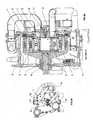
- FIGS. 4a and 4bshow: inward head surfaces (D) of the piston portions of plungers 6 inside the tube 15, so that the two surfaces D are facing each other; outward surfaces (C) of the piston portions of plungers 6 facing the bushings 18; an internal space (A) formed between the inward surfaces D and the inner sidewalls of the tube 15; external spaces (B) formed between the outward surfaces C, the rod portion sidewalls and the inner sidewalls of the bushings 18.
- the oil pumpincludes two oil drain pipes (21), each communicating the external spaces B with the oil suction inlet ( FIGS. 4a and 4b ).
- Each plunger 6includes a through throttling channel (22) drilled preferably along the longitudinal axe of plunger 6 with a predeterminedly small diameter to provide necessary resistance to the oil cross-flow therethrough.
- the purpose of making the channel 22is to prevent the device from destroying by a hydro-impact during its operation.
- the channel 22has a perpendicular through portion capable to communicate the channel 22 with the space B.
- a first functionis the pumping of oil, which is a regular lubrication function common for an oil pump.
- a second function of the plungers 6is the absorption of side forces caused by the interaction between the rollers 5 and the rotor 8. Since the gap between the sleeve 2 and the piston 3 is essentially greater than the gap between the pump tube 15 arid the plunger 6 (the size of 50 micrometers against the size of from 2 micrometers to 4 micrometers respectively), the plunger 6 absorbs the aforesaid side forces.
- a third function of the plungers 6is the providing for parallel movement of the pistons 3 within the sleeve 2 due to the absorption of aforesaid side forces.
- a fourth function of the plungers 6is the providing for a predetermined volume of the combustion chamber and for absorption of inertial forces developed by the pistons 3 and substantially exerted onto the rotor 8. This is achieved due to operation of the plungers 6 as "hydro-lock" valves in a hydro-system in the uppermost and lowermost dead points of the piston's traveling.
- FIG. 1billustrates the positions of the pistons 3 with the traverses 4 situated in the uppermost dead-point wherein a common combustion chamber is formed by the pistons' heads and a respective portion of the sleeve's inner sidewalls (the uppermost dead-point corresponds to the minimal volume of the common combustion chamber).
- a sparkis produced by the spark-plug 16, igniting the fuel-air mixture in the combustion chamber that moves the pistons 3 with the traverses 4 in the opposite directions.
- the rollers 5depress the rotor's inner curved operation surface, impelling the rotor 8 to spin, which rotates the takeoff shaft 9.
- the inlet port 12 and outlet port 13are opened that provides for blowing the combustion products out and filling up the cylinder's sleeve 2 with a portion of fresh air supplied by the compressor 14.
- the rotor 8spins due to inertia, pushing the pistons 3 via the rollers 5 and traverses 4, which results in the movement of pistons towards each other up to the uppermost dead-point, compressing the air in the sleeve 2.
- the pistons 5pass the inlet port 12 and the outlet port 13, a portion of fuel is injected into the combustion chamber through the injector 17.
- the mixture of fuel and airis intensely intermingled in the chamber up to the uppermost dead-point position of the pistons 3 (shown in FIG. 1b ).
- the space Ais contracting ( FIG. 4b ) and oil is ejected therefrom by the surfaces D into the withdraw conduit 20 via the oil discharge outlet. After the surface D passes the oil suction inlet, the oil left in the space A is confined and forms a hydro-lock in the space A, which determines the position of the uppermost dead-point of the engine.
Landscapes
- Engineering & Computer Science (AREA)
- Mechanical Engineering (AREA)
- General Engineering & Computer Science (AREA)
- Chemical & Material Sciences (AREA)
- Combustion & Propulsion (AREA)
- Lubrication Of Internal Combustion Engines (AREA)
- Hydraulic Motors (AREA)
- Actuator (AREA)
Description
- This application claims priority of a
U.S. provisional patent application Ser. No 60/881208, filed on 19 January 2007 U.S. nonprovisional patent application Ser. No 11/827595 filed on 12 July 2007 - The invention relates to opposite radial rotary-piston engines that can be utilized in ground vehicles, water vehicles, aircraft, in combinations with generators, etc.
- In the prior art there are known several constructions of centrifugal-piston or rotary-piston engines (herein further called ORPE), which are intended to eliminate certain disadvantages of conventional piston engines. E.g., such constructions are described in
DE3907307 ,US6279518 ,WO2005098202 ,RU2143572 JP7113452 DE3907307 discloses a four-stroke engine wherein a cylinder block revolves inside a rotor, which is complicated, has a small resource of the valve system, and a des-balance with the revolving system including movable parts.US6279518 discloses a four-stroke engine having a valve system and a conically shaped rotor. Fig. 7 shows a conical rotor with an elliptical groove, and a series of pistons followers inside the groove. It is a complicated unit with substantial friction losses, which has a limited operation resource for its loaded parts. The construction does not eliminate the side forces exerted by the piston upon the cylinder walls.RU 2143572 - From the inventors' point of view, a more advanced design of OPRE is presented in
US6161508 . It describes "a radial-piston engine of rotary type of the kind having a valve system comprising apertured disc rings arranged in intersliding relationship, one of said rings being stationary while the other one is arranged to take part in the rotary motion of the rotor. The valve opening relationship is determined by the manual angular positions of the discs. In accordance with the invention, filed injection takes place via an injection nozzle positioned in the stationary disc. The valve ring is formed with a through opening which in response to the position assumed my the rotor at the moment of fuel ignition forms an open communication means between the injection nozzle and the combustion chamber." - That engine however has also certain drawbacks and limitations. It is built as a four-stroke engine having a cylinder block revolving around and impelling a rotor. Reaction forces produced in support bearings are very significant that leads to a short operation resource period. It uses an inlet / outlet system based on a rotatable sliding valve. This necessitates the use of complicated sealing means that, as a rule, have very limited operation resource (typically 100 hours maximum). The rotating cylinder block with linearly reciprocating pistons is very hard to balance, and thusly will cause intensive destructive vibrations. These problems are successfully resolved in the present invention.
- The inventive ORPE employs the mentioned non-typical form of conversion of the spinning motion of a rotor into a progressive linear stroke of a piston, and vice versa. This constructive solution provides for substantial absorption of side forces exerted by the piston onto engine cylinder's walls and vice-versa, and for an essential improvement of the weight and fuel consumption / power output ratios, demonstrating useful advantages over all presently utilized engines known to the inventors, including the Wankel rotor engine.
- The most important advantages of the invention are a simple design, low mass, long operation resource (supposedly over 1,000,000 km), low fuel consumption and high power torque, low level of pollutions (environmentally-friendly).
- The engine's weight (without attached devices) is estimated about 30 kg. It has a displacement of 500 cc, and should deliver a 250 horse-power. In a more powerful version, the engine's own weight is estimated 65 kg (without attached devices), having a displacement of 1000 cc and should deliver a 500 horse-power.
- The engines as described in the invention may be employed in different applications, such as for joint operation with generators, water and surface vehicles motors, for aircraft motors, and capable to successfully compete with traditional internal combustion engines.
- The design solutions embodied in the engine's lubrication and cooling systems allow exploiting the engine at 12000-15000 rpm, which can provide for an efficient motor sports application. The construction described in the present disclosure allows developing and manufacturing engines fueled by gasoline or natural gas, as well as diesel type engines employing the inventive principles.
- The inventive ORPE has a rotor's operation surface formed by a closed symmetrical ellipse-type line


- The present disclosure describes a two-stroke opposite rotary-piston engine that comprises a cylinder block including a sleeve and two pistons slidely disposed therein arid oppositely movable, which pistons are forming a common combustion chamber situated between their heads, and forming a first gap with sleeve's sidewalls; a rotor having a surface formed by an ellipse or Cassini line; traverses attached to the pistons; rollers attached to the traverses and springly depressed against the rotor; oil tubes with end bushings; oil supply and withdraw means; two plungers disposed in each tube forming a second gap with the tube's sidewalls, essentially less than the first gap. The plungers are attached to the traverses and oppositely movable, also including through throttling channels, outward surfaces forming external spaces with the bushings, and inward surfaces forming an internal space with the tube sidewalls, which internal space communicates with the oil supply means and the oil withdraw means. Engine's oil drain means communicate the external spaces with the oil supply means. The engine absorbs side and inertial forces, is more efficient and clean.
FIG. 1a illustrates a general frontal view of the assembled engine, according to a preferred embodiment of the present invention. 'FIG. 1b illustrates a side sectional view of the engine in the uppermost "dead point" of the rotor and shows base units and details of the engine's construction, according to a preferred embodiment of the present invention.FIG. 2a illustrates a general frontal view of the assembled engine, according to a preferred embodiment of the present invention.FIG. 2b illustrates a side sectional view of the engine in the lowermost "dead point" of the rotor and shows base units and parts of the engine's construction, according to a preferred embodiment of the present invention.FIG. 3a illustrates a general side view of the assembled engine, according to a preferred embodiment of the present invention.FIG. 3b illustrates a frontal sectional view of the engine, showing the design of the plungers, plungers' tubes, and other base units and parts of the engine's construction, according to a preferred embodiment of the present invention.FIG. 4a illustrates a sectional view of the plungers' tubes and plungers at the lowermost dead-point of the engine, according to a preferred embodiment of the present invention.FIG. 4b illustrates a sectional view of the plungers' tubes and plungers at the uppermost dead-point of the engine, according to a preferred embodiment of the present invention.- Similar reference numerals in the drawings generally refer to the same or similar elements in different figures. A newly introduced numeral in the description is enclosed into parentheses.
- While the invention may be susceptible to embodiment in different forms, there is shown in the drawings, and will be described in detail herein, a specific embodiment of the present invention, with the understanding that the present disclosure is to be considered an exemplification of the principles of the invention, and is not intended to limit the invention to that as illustrated and described herein.
- An embodiment of the inventive engine, fueled by gasoline, is illustrated in
FIGS. 1a, 1b ,2a, 2b ,3a, and 3b . The engine comprises a stationary cylinder block (1) fixedly mounted, e.g. on a vehicle; a cylindrically shaped sleeve (2) mounted to theblock 1; two oppositely movable cylindrical pistons (3) slidely snug-fitting in thesleeve 2. In a preferred embodiment, a first gap between thepiston 3 and the sidewalls of thesleeve 2 is made in the size of about 50 micrometers. - The
opposite pistons 3 each includes a bottom head. The surfaces of the bottom heads and a portion of sidewalls of the sleeve 2 (between the bottom heads) collectively form a common work chamber and a common combustion chamber. - The
block 1 includes a supporting bearing (preferably ball-bearing). A spark-plug (16) and an injector (17) are installed in theblock 1. - The
block 1 andsleeve 2 include an inlet port (12) and outlet port (13), preferably milled out therein, to provide air supply and combustion products exhaust correspondingly. The air supply is introduced from a supercharging air compressor (14), in this embodiment mechanically driven by the engine. In other embodiments, it may be driven by other means. Thecompressor 14 is connected to theinlet port 12. - The engine comprises two fork-shaped traverses (4), each
aforesaid traverse 4 is coupled with one of thepistons 3 by means of lock-nuts with a female threading screwable on a male threading of the traverse. The threading connection allows adjusting the compression ratio within a range of from 8 to 11 during the assembly process. - The engine comprises supporting rollers (5) to transmit forces from the
pistons 3 and traverses 4, whichrollers 5 are mounted to thetraverses 4 by means of pins (not shown). - The engine comprises a stationary housing (11) fixedly mounted, e.g. on a vehicle. The
housing 11 includes a supporting bearing (10) (preferably, a ball bearing). InFIGS. 1a, 1b ,2a, 2b , thehousing 11 is conventionally shown vertically positioned, though in reality it is typically positioned horizontally. Thehousing 11 is filled up with oil for lubrication and other purposes as described further in the disclosure. - The engine comprises a rotor (8), having a closed inner operation surface formed by a predeterminedly curved line, for example, a closed symmetrical ellipse-type line or Cassini line mentioned hereinabove. The
rotor 8 is mounted on the supporting bearing installed within thehousing 11 and on the supporting bearing installed within thecylinder block 1. - The engine comprises a rotatable power takeoff shaft (9) mounted at least on the supporting
bearing 10. Theshaft 9 is fixed to therotor 8. The rotation torque of therotor 8 is transmitted to theshaft 9 and can be further conveyed to a transmission. - The
traverses 4 interact with springs (7), which springs depress the supportingrollers 5 against therotor 8, providing for a mild unstressed engaging at engine's start. - As depicted in
FIGS. 4a and 4b , the engine comprises an oil supply conduit (19) of low pressure with a reverse valve (not shown) mounted therein, and an oil withdraw conduit (20) of high pressure with a reverse valve and a pressure-reduction valve (both not shown) mounted therein. Theconduits housing 11, and used at least for lubrication of the engine and other purposes disclosed below. - The engine comprises an oil pump, shown in
FIGS. 3b ,4a, 4b including two sections, each comprising a tube (15) and two opposite plungers (6) slidely snug-fitting within eachtube 15. Eachplunger 6 has a piston portion and a rod portion. The rod portions ofplungers 6 are attached to the traverses 4 (as shown inFIG. 3b ) by means of pins (not shown). In a preferred embodiment, a second gap between thepump tube 15 and theplungers 6 is made in the size of about 2 - 4 micrometers, i.e. essentially less than the first gap. - The
tube 15 has an oil suction inlet connected to theoil supply conduit 19 and an oil discharge outlet connected to the oil withdrawconduit 20, which inlet and outlet are drilled in the pump tubes, as depicted inFIGS. 4a and 4b . - The oil pump includes guide bushings (18) coupled to both the ends of each
tube 15, as shown inFIG. 4a . Thebushings 18 serve to close thetube 15 at its ends, and to guide the linear movement of the rod portion ofplunger 6. FIGS. 4a and 4b show: inward head surfaces (D) of the piston portions ofplungers 6 inside thetube 15, so that the two surfaces D are facing each other; outward surfaces (C) of the piston portions ofplungers 6 facing thebushings 18; an internal space (A) formed between the inward surfaces D and the inner sidewalls of thetube 15; external spaces (B) formed between the outward surfaces C, the rod portion sidewalls and the inner sidewalls of thebushings 18.- The oil pump includes two oil drain pipes (21), each communicating the external spaces B with the oil suction inlet (
FIGS. 4a and 4b ). - Each
plunger 6 includes a through throttling channel (22) drilled preferably along the longitudinal axe ofplunger 6 with a predeterminedly small diameter to provide necessary resistance to the oil cross-flow therethrough. The purpose of making thechannel 22 is to prevent the device from destroying by a hydro-impact during its operation. Thechannel 22 has a perpendicular through portion capable to communicate thechannel 22 with the space B. - The
plungers 6 perform several important functions in the engine. A first function is the pumping of oil, which is a regular lubrication function common for an oil pump. - A second function of the
plungers 6 is the absorption of side forces caused by the interaction between therollers 5 and therotor 8. Since the gap between thesleeve 2 and thepiston 3 is essentially greater than the gap between thepump tube 15 arid the plunger 6 (the size of 50 micrometers against the size of from 2 micrometers to 4 micrometers respectively), theplunger 6 absorbs the aforesaid side forces. - A third function of the
plungers 6 is the providing for parallel movement of thepistons 3 within thesleeve 2 due to the absorption of aforesaid side forces. - A fourth function of the
plungers 6 is the providing for a predetermined volume of the combustion chamber and for absorption of inertial forces developed by thepistons 3 and substantially exerted onto therotor 8. This is achieved due to operation of theplungers 6 as "hydro-lock" valves in a hydro-system in the uppermost and lowermost dead points of the piston's traveling. FIG. 1b illustrates the positions of thepistons 3 with thetraverses 4 situated in the uppermost dead-point wherein a common combustion chamber is formed by the pistons' heads and a respective portion of the sleeve's inner sidewalls (the uppermost dead-point corresponds to the minimal volume of the common combustion chamber). In the positions, a spark is produced by the spark-plug 16, igniting the fuel-air mixture in the combustion chamber that moves thepistons 3 with thetraverses 4 in the opposite directions. Therollers 5 depress the rotor's inner curved operation surface, impelling therotor 8 to spin, which rotates thetakeoff shaft 9.- During the further traveling of the
pistons 3 up to a 90 degrees turn of the rotor 8 (the lowermost dead-point corresponds to the maximal volume of the common combustion chamber, depicted inFIG. 2b ), theinlet port 12 andoutlet port 13 are opened that provides for blowing the combustion products out and filling up the cylinder'ssleeve 2 with a portion of fresh air supplied by thecompressor 14. - During the next 90 degrees turn (not illustrated), the
rotor 8 spins due to inertia, pushing thepistons 3 via therollers 5 and traverses 4, which results in the movement of pistons towards each other up to the uppermost dead-point, compressing the air in thesleeve 2. After thepistons 5 pass theinlet port 12 and theoutlet port 13, a portion of fuel is injected into the combustion chamber through theinjector 17. The mixture of fuel and air is intensely intermingled in the chamber up to the uppermost dead-point position of the pistons 3 (shown inFIG. 1b ). - When a 180 degree turn of the
rotor 8 is completed, the next spark is produced in the combustion chamber and the above-described two-stroke cycle is repeated. Therefore, the two-stroke cycle is performed during a 180-degree turn of the takeoff shaft, whereas, in a traditional piston internal combustion engine and all the aforementioned prior art engines, a two-stroke cycle is performed during a 360 degree turn. This doubles the frequency of the engine's cycles, resulting in an increase of its power. - Parallel processes occur in the
oil tubes 15 andplungers 6 during operation of the engine. At the time when thepistons 3 travel to the lowermost dead-point, oil is sucked from thehousing 11 into thesupply conduit 19, and, via the oil suction inlet, into the expanding space A of the tube 15 (FIG. 4a ). Simultaneously, oil is ejected from the space B into thedrain pipes 21 by means of the inward surfaces C. - After the surfaces C pass the
drain pipes 21, they will be closed by the piston portions of theplungers 6, and the oil left in the spaces B will prevent the further movement of theplungers 6 and, thusly, prevent the movement of thepistons 3 associated with theplungers 6 through thetraverses 4. This situation is known as a "hydro-lock" in the space B, and it causes the lowermost dead-point of the engine. Theaforementioned throttling channels 22 prevent the plungers and other mechanisms associated therewith from destroying by a hydro-impact taking place at the abrupt stop of theplungers 6, caused by the hydro-lock. - During the reverse movement of the
plungers 6, the space A is contracting (FIG. 4b ) and oil is ejected therefrom by the surfaces D into the withdrawconduit 20 via the oil discharge outlet. After the surface D passes the oil suction inlet, the oil left in the space A is confined and forms a hydro-lock in the space A, which determines the position of the uppermost dead-point of the engine. - Due to the absence of a crank-shaft, the side forces taking place in the crank-shaft and inertial loads caused by the crank-shaft rotation are substantially eliminated. This reduces friction losses by about 50%, and accordingly lessens the fuel consumption and saves a fuel amount necessary to cover the friction losses. The fuel efficiency of the engine leads to reduction of pollutions that makes the engine environmentally friendly.


Claims (3)
- A two-stroke opposite radial rotary-piston engine comprising
a stationary housing;
a stationary cylinder block assembled with the housing, said block including
a cylindrically shaped sleeve having inner sidewalls, and two cylindrical pistons each having a bottom head facing each other, said pistons slidely disposed in the sleeve so that a first gap of a predetermined size being formed between the inner sidewalls of said sleeve and the pistons, said pistons being oppositely movable in relation to each other so that a common work chamber and a common combustion chamber formed by the bottom heads and the inner sidewalls of said sleeve;
a rotor having a closed inner operation surface formed by a predeterminedly curved line, said rotor is revolvably supported substantially by the housing and the cylinder block;
two traverses each attached to one of said pistons;
a number of support rollers attached to each of said traverses, said rollers being springly depressed against said rotor;
two stationary oil pump tubes, said tubes closed from both ends with guide bushings, said tubes including tube's inner sidewalls, said bushings including bushings' inner sidewalls;
oil supply means for at least supplying oil into said tubes;
oil withdraw means for at least withdrawing oil from said tubes;
two plungers slidely disposed within each of said tubes so that a second gap of a predetermined size being formed between the plungers and the tube's inner sidewalls, the size of the first gap being essentially greater than the size of the second gap, said plungers attached to said traverses and oppositely movable in relation to each other being guided by the guide bushings, said plungers each including a longitudinal through throttling channel and an outward surface, said bushings' inner sidewalls and said outward surfaces substantially forming two external spaces, said plungers each including an inward surface, said inward surfaces and said tube's inner sidewalls forming an internal space, said internal space communicating with said oil supply means and said oil withdraw means; and
oil drain means for communicating the external spaces with said oil supply means. - The engine according to claim 1, wherein
the predetermined curved line being either a closed symmetrical ellipse-type line or a Cassini line. - The engine according to claim 1, wherein
the predetermined size of the first gap being equal substantially to 50 micrometers, and the predetermined size of the second gap being chosen from the range of from 2 to 4 micrometers.
Applications Claiming Priority (2)
| Application Number | Priority Date | Filing Date | Title |
|---|---|---|---|
| US11/827,595US7584726B2 (en) | 2007-01-19 | 2007-07-12 | Two-stroke opposite radial rotary-piston engine |
| PCT/IB2008/000471WO2008087554A2 (en) | 2007-01-19 | 2008-01-16 | Two-stroke opposite radial rotary-piston engine |
Publications (3)
| Publication Number | Publication Date |
|---|---|
| EP2240674A2 EP2240674A2 (en) | 2010-10-20 |
| EP2240674A4 EP2240674A4 (en) | 2013-08-28 |
| EP2240674B1true EP2240674B1 (en) | 2016-01-13 |
Family
ID=41728597
Family Applications (1)
| Application Number | Title | Priority Date | Filing Date |
|---|---|---|---|
| EP08719206.8ANot-in-forceEP2240674B1 (en) | 2007-07-12 | 2008-01-16 | Two-stroke opposite radial rotary-piston engine |
Country Status (10)
| Country | Link |
|---|---|
| EP (1) | EP2240674B1 (en) |
| JP (1) | JP5074589B2 (en) |
| KR (1) | KR101368521B1 (en) |
| AU (1) | AU2008206784A1 (en) |
| DK (1) | DK2240674T3 (en) |
| EA (1) | EA201070142A1 (en) |
| ES (1) | ES2561107T3 (en) |
| MX (1) | MX2010000487A (en) |
| UA (1) | UA99472C2 (en) |
| ZA (1) | ZA201001021B (en) |
Family Cites Families (8)
| Publication number | Priority date | Publication date | Assignee | Title |
|---|---|---|---|---|
| DE372808C (en)* | 1921-11-01 | 1923-04-05 | Hermann Michel | Internal combustion engine with fixed cylinders and rotating flywheels |
| JPS5261609A (en)* | 1975-11-17 | 1977-05-21 | Combustion Res & Tech | Reciprocating motion rotary engine |
| EP0280200B1 (en)* | 1987-02-25 | 1992-05-06 | Sampower Oy | Power aggregate |
| AUPM982794A0 (en) | 1994-12-02 | 1995-01-05 | Advanced Engine Technology Pty Ltd | New and improved rotary engine |
| SE508376C2 (en)* | 1996-07-12 | 1998-09-28 | Gul & Co Dev Ab | Lubrication device for internal combustion engine with power transmission via a cam curve track |
| SE508377C2 (en)* | 1996-07-12 | 1998-09-28 | Gul & Co Dev Ab | Device for power machine with two pistons |
| AUPO157396A0 (en) | 1996-08-09 | 1996-09-05 | Aust Tech Pty. Ltd. | Improvements in axial piston rotary engines |
| US6948458B2 (en)* | 2003-02-12 | 2005-09-27 | Amorn Ariyakunakorn | Two-way cylinder engine |
- 2008
- 2008-01-16EPEP08719206.8Apatent/EP2240674B1/ennot_activeNot-in-force
- 2008-01-16AUAU2008206784Apatent/AU2008206784A1/ennot_activeAbandoned
- 2008-01-16MXMX2010000487Apatent/MX2010000487A/enactiveIP Right Grant
- 2008-01-16KRKR1020107002861Apatent/KR101368521B1/enactiveActive
- 2008-01-16ESES08719206.8Tpatent/ES2561107T3/enactiveActive
- 2008-01-16DKDK08719206.8Tpatent/DK2240674T3/enactive
- 2008-01-16UAUAA201001435Apatent/UA99472C2/enunknown
- 2008-01-16EAEA201070142Apatent/EA201070142A1/enunknown
- 2008-01-16JPJP2010515616Apatent/JP5074589B2/ennot_activeExpired - Fee Related
- 2010
- 2010-02-11ZAZA2010/01021Apatent/ZA201001021B/enunknown
Also Published As
| Publication number | Publication date |
|---|---|
| KR101368521B1 (en) | 2014-02-27 |
| EP2240674A4 (en) | 2013-08-28 |
| JP5074589B2 (en) | 2012-11-14 |
| DK2240674T3 (en) | 2016-02-29 |
| EA201070142A1 (en) | 2010-10-29 |
| ES2561107T3 (en) | 2016-02-24 |
| EP2240674A2 (en) | 2010-10-20 |
| AU2008206784A1 (en) | 2008-07-24 |
| JP2011503404A (en) | 2011-01-27 |
| KR20100045996A (en) | 2010-05-04 |
| MX2010000487A (en) | 2010-05-03 |
| UA99472C2 (en) | 2012-08-27 |
| ZA201001021B (en) | 2012-09-29 |
Similar Documents
| Publication | Publication Date | Title |
|---|---|---|
| CN102282347B (en) | rotary piston engine | |
| JP5629371B2 (en) | Planetary rotary fluid motor or motor and compressor or pump | |
| KR100922024B1 (en) | Reciprocating Piston Engine | |
| US6270322B1 (en) | Internal combustion engine driven hydraulic pump | |
| US4144866A (en) | Internal combustion rotary engine | |
| CN106662007A (en) | free piston engine | |
| KR20020065541A (en) | Apparatus using oscillating rotating pistons | |
| US8161924B1 (en) | Orbital, non-reciprocating, internal combustion engine | |
| CN1278888A (en) | A radial motor or pump | |
| US20020007815A1 (en) | O-ring type rotary engine | |
| US6032622A (en) | Internal combustion cylinder engine | |
| EP0717812B1 (en) | Engine | |
| US6357397B1 (en) | Axially controlled rotary energy converters for engines and pumps | |
| CN101173629B (en) | Rotating internal combustion engine with double-speed transmission rotor pair | |
| US7621254B2 (en) | Internal combustion engine with toroidal cylinders | |
| US7584726B2 (en) | Two-stroke opposite radial rotary-piston engine | |
| EP2240674B1 (en) | Two-stroke opposite radial rotary-piston engine | |
| JP3377968B2 (en) | Internal combustion rotary engine and compressor | |
| CN103628977B (en) | A kind of two water chestnut rotary engine | |
| CN113250819A (en) | Device for transmitting power by using straight rod piston seven-wheel transmission mechanism and application thereof | |
| CN101787926B (en) | Cam mechanism inside internal combustion engine with piston doing circular motion | |
| US20090314250A1 (en) | Opposite radial rotary-piston engine of Choronski | |
| CN101787927B (en) | Circularly moving piston internal combustion engine | |
| WO1986004637A1 (en) | Axial shaft piston engine | |
| CN102787911A (en) | Superimposed rotary engine |
Legal Events
| Date | Code | Title | Description |
|---|---|---|---|
| PUAI | Public reference made under article 153(3) epc to a published international application that has entered the european phase | Free format text:ORIGINAL CODE: 0009012 | |
| 17P | Request for examination filed | Effective date:20100211 | |
| AK | Designated contracting states | Kind code of ref document:A2 Designated state(s):AT BE BG CH CY CZ DE DK EE ES FI FR GB GR HR HU IE IS IT LI LT LU LV MC MT NL NO PL PT RO SE SI SK TR | |
| R17D | Deferred search report published (corrected) | Effective date:20120426 | |
| RIC1 | Information provided on ipc code assigned before grant | Ipc:F02B 25/00 20060101ALI20120802BHEP Ipc:F01B 7/14 20060101AFI20120802BHEP | |
| A4 | Supplementary search report drawn up and despatched | Effective date:20130726 | |
| RIC1 | Information provided on ipc code assigned before grant | Ipc:F01B 7/14 20060101AFI20130722BHEP Ipc:F01B 7/02 20060101ALI20130722BHEP Ipc:F01B 1/06 20060101ALI20130722BHEP Ipc:F02B 25/00 20060101ALI20130722BHEP | |
| REG | Reference to a national code | Ref country code:DE Ref legal event code:R079 Ref document number:602008042007 Country of ref document:DE Free format text:PREVIOUS MAIN CLASS: F02B0075280000 Ipc:F01B0007140000 | |
| RIC1 | Information provided on ipc code assigned before grant | Ipc:F01B 7/14 20060101AFI20140909BHEP Ipc:F02B 25/00 20060101ALI20140909BHEP Ipc:F01B 7/02 20060101ALI20140909BHEP Ipc:F01B 1/06 20060101ALI20140909BHEP | |
| GRAP | Despatch of communication of intention to grant a patent | Free format text:ORIGINAL CODE: EPIDOSNIGR1 | |
| INTG | Intention to grant announced | Effective date:20141216 | |
| GRAS | Grant fee paid | Free format text:ORIGINAL CODE: EPIDOSNIGR3 | |
| RAP1 | Party data changed (applicant data changed or rights of an application transferred) | Owner name:MOUKHAEV, BORIS Owner name:KHORONSKIY, EVGENIY | |
| RIN1 | Information on inventor provided before grant (corrected) | Inventor name:KHORONSKIY, EVGENIY Inventor name:MOUKHAEV, BORIS | |
| GRAA | (expected) grant | Free format text:ORIGINAL CODE: 0009210 | |
| AK | Designated contracting states | Kind code of ref document:B1 Designated state(s):AT BE BG CH CY CZ DE DK EE ES FI FR GB GR HR HU IE IS IT LI LT LU LV MC MT NL NO PL PT RO SE SI SK TR | |
| REG | Reference to a national code | Ref country code:GB Ref legal event code:FG4D | |
| REG | Reference to a national code | Ref country code:CH Ref legal event code:EP | |
| REG | Reference to a national code | Ref country code:IE Ref legal event code:FG4D | |
| REG | Reference to a national code | Ref country code:AT Ref legal event code:REF Ref document number:770660 Country of ref document:AT Kind code of ref document:T Effective date:20160215 | |
| REG | Reference to a national code | Ref country code:ES Ref legal event code:FG2A Ref document number:2561107 Country of ref document:ES Kind code of ref document:T3 Effective date:20160224 | |
| REG | Reference to a national code | Ref country code:DE Ref legal event code:R096 Ref document number:602008042007 Country of ref document:DE | |
| REG | Reference to a national code | Ref country code:DK Ref legal event code:T3 Effective date:20160225 Ref country code:FR Ref legal event code:PLFP Year of fee payment:9 | |
| REG | Reference to a national code | Ref country code:SE Ref legal event code:TRGR | |
| REG | Reference to a national code | Ref country code:LT Ref legal event code:MG4D | |
| REG | Reference to a national code | Ref country code:NL Ref legal event code:MP Effective date:20160113 | |
| PG25 | Lapsed in a contracting state [announced via postgrant information from national office to epo] | Ref country code:NL Free format text:LAPSE BECAUSE OF FAILURE TO SUBMIT A TRANSLATION OF THE DESCRIPTION OR TO PAY THE FEE WITHIN THE PRESCRIBED TIME-LIMIT Effective date:20160113 | |
| PG25 | Lapsed in a contracting state [announced via postgrant information from national office to epo] | Ref country code:FI Free format text:LAPSE BECAUSE OF FAILURE TO SUBMIT A TRANSLATION OF THE DESCRIPTION OR TO PAY THE FEE WITHIN THE PRESCRIBED TIME-LIMIT Effective date:20160113 Ref country code:GR Free format text:LAPSE BECAUSE OF FAILURE TO SUBMIT A TRANSLATION OF THE DESCRIPTION OR TO PAY THE FEE WITHIN THE PRESCRIBED TIME-LIMIT Effective date:20160414 Ref country code:HR Free format text:LAPSE BECAUSE OF FAILURE TO SUBMIT A TRANSLATION OF THE DESCRIPTION OR TO PAY THE FEE WITHIN THE PRESCRIBED TIME-LIMIT Effective date:20160113 Ref country code:NO Free format text:LAPSE BECAUSE OF FAILURE TO SUBMIT A TRANSLATION OF THE DESCRIPTION OR TO PAY THE FEE WITHIN THE PRESCRIBED TIME-LIMIT Effective date:20160413 | |
| PG25 | Lapsed in a contracting state [announced via postgrant information from national office to epo] | Ref country code:IS Free format text:LAPSE BECAUSE OF FAILURE TO SUBMIT A TRANSLATION OF THE DESCRIPTION OR TO PAY THE FEE WITHIN THE PRESCRIBED TIME-LIMIT Effective date:20160513 Ref country code:PL Free format text:LAPSE BECAUSE OF FAILURE TO SUBMIT A TRANSLATION OF THE DESCRIPTION OR TO PAY THE FEE WITHIN THE PRESCRIBED TIME-LIMIT Effective date:20160113 Ref country code:PT Free format text:LAPSE BECAUSE OF FAILURE TO SUBMIT A TRANSLATION OF THE DESCRIPTION OR TO PAY THE FEE WITHIN THE PRESCRIBED TIME-LIMIT Effective date:20160513 Ref country code:LV Free format text:LAPSE BECAUSE OF FAILURE TO SUBMIT A TRANSLATION OF THE DESCRIPTION OR TO PAY THE FEE WITHIN THE PRESCRIBED TIME-LIMIT Effective date:20160113 Ref country code:LT Free format text:LAPSE BECAUSE OF FAILURE TO SUBMIT A TRANSLATION OF THE DESCRIPTION OR TO PAY THE FEE WITHIN THE PRESCRIBED TIME-LIMIT Effective date:20160113 | |
| REG | Reference to a national code | Ref country code:CH Ref legal event code:PL | |
| REG | Reference to a national code | Ref country code:DE Ref legal event code:R097 Ref document number:602008042007 Country of ref document:DE | |
| PG25 | Lapsed in a contracting state [announced via postgrant information from national office to epo] | Ref country code:MC Free format text:LAPSE BECAUSE OF FAILURE TO SUBMIT A TRANSLATION OF THE DESCRIPTION OR TO PAY THE FEE WITHIN THE PRESCRIBED TIME-LIMIT Effective date:20160113 Ref country code:LI Free format text:LAPSE BECAUSE OF NON-PAYMENT OF DUE FEES Effective date:20160131 Ref country code:EE Free format text:LAPSE BECAUSE OF FAILURE TO SUBMIT A TRANSLATION OF THE DESCRIPTION OR TO PAY THE FEE WITHIN THE PRESCRIBED TIME-LIMIT Effective date:20160113 Ref country code:CH Free format text:LAPSE BECAUSE OF NON-PAYMENT OF DUE FEES Effective date:20160131 | |
| REG | Reference to a national code | Ref country code:IE Ref legal event code:MM4A | |
| PLBE | No opposition filed within time limit | Free format text:ORIGINAL CODE: 0009261 | |
| STAA | Information on the status of an ep patent application or granted ep patent | Free format text:STATUS: NO OPPOSITION FILED WITHIN TIME LIMIT | |
| PG25 | Lapsed in a contracting state [announced via postgrant information from national office to epo] | Ref country code:SK Free format text:LAPSE BECAUSE OF FAILURE TO SUBMIT A TRANSLATION OF THE DESCRIPTION OR TO PAY THE FEE WITHIN THE PRESCRIBED TIME-LIMIT Effective date:20160113 Ref country code:CZ Free format text:LAPSE BECAUSE OF FAILURE TO SUBMIT A TRANSLATION OF THE DESCRIPTION OR TO PAY THE FEE WITHIN THE PRESCRIBED TIME-LIMIT Effective date:20160113 Ref country code:RO Free format text:LAPSE BECAUSE OF FAILURE TO SUBMIT A TRANSLATION OF THE DESCRIPTION OR TO PAY THE FEE WITHIN THE PRESCRIBED TIME-LIMIT Effective date:20160113 | |
| 26N | No opposition filed | Effective date:20161014 | |
| PG25 | Lapsed in a contracting state [announced via postgrant information from national office to epo] | Ref country code:IE Free format text:LAPSE BECAUSE OF NON-PAYMENT OF DUE FEES Effective date:20160116 | |
| PG25 | Lapsed in a contracting state [announced via postgrant information from national office to epo] | Ref country code:SI Free format text:LAPSE BECAUSE OF FAILURE TO SUBMIT A TRANSLATION OF THE DESCRIPTION OR TO PAY THE FEE WITHIN THE PRESCRIBED TIME-LIMIT Effective date:20160113 Ref country code:BG Free format text:LAPSE BECAUSE OF FAILURE TO SUBMIT A TRANSLATION OF THE DESCRIPTION OR TO PAY THE FEE WITHIN THE PRESCRIBED TIME-LIMIT Effective date:20160413 | |
| PG25 | Lapsed in a contracting state [announced via postgrant information from national office to epo] | Ref country code:BE Free format text:LAPSE BECAUSE OF NON-PAYMENT OF DUE FEES Effective date:20170131 | |
| REG | Reference to a national code | Ref country code:FR Ref legal event code:PLFP Year of fee payment:10 | |
| PG25 | Lapsed in a contracting state [announced via postgrant information from national office to epo] | Ref country code:MT Free format text:LAPSE BECAUSE OF FAILURE TO SUBMIT A TRANSLATION OF THE DESCRIPTION OR TO PAY THE FEE WITHIN THE PRESCRIBED TIME-LIMIT Effective date:20160113 | |
| REG | Reference to a national code | Ref country code:AT Ref legal event code:UEP Ref document number:770660 Country of ref document:AT Kind code of ref document:T Effective date:20160113 | |
| PG25 | Lapsed in a contracting state [announced via postgrant information from national office to epo] | Ref country code:CY Free format text:LAPSE BECAUSE OF FAILURE TO SUBMIT A TRANSLATION OF THE DESCRIPTION OR TO PAY THE FEE WITHIN THE PRESCRIBED TIME-LIMIT Effective date:20160113 Ref country code:HU Free format text:LAPSE BECAUSE OF FAILURE TO SUBMIT A TRANSLATION OF THE DESCRIPTION OR TO PAY THE FEE WITHIN THE PRESCRIBED TIME-LIMIT; INVALID AB INITIO Effective date:20080116 | |
| PG25 | Lapsed in a contracting state [announced via postgrant information from national office to epo] | Ref country code:LU Free format text:LAPSE BECAUSE OF NON-PAYMENT OF DUE FEES Effective date:20160116 Ref country code:MT Free format text:LAPSE BECAUSE OF FAILURE TO SUBMIT A TRANSLATION OF THE DESCRIPTION OR TO PAY THE FEE WITHIN THE PRESCRIBED TIME-LIMIT Effective date:20160131 Ref country code:TR Free format text:LAPSE BECAUSE OF FAILURE TO SUBMIT A TRANSLATION OF THE DESCRIPTION OR TO PAY THE FEE WITHIN THE PRESCRIBED TIME-LIMIT Effective date:20160113 | |
| REG | Reference to a national code | Ref country code:FR Ref legal event code:PLFP Year of fee payment:11 | |
| PGFP | Annual fee paid to national office [announced via postgrant information from national office to epo] | Ref country code:IT Payment date:20230727 Year of fee payment:16 Ref country code:GB Payment date:20230717 Year of fee payment:16 Ref country code:ES Payment date:20230726 Year of fee payment:16 Ref country code:AT Payment date:20230719 Year of fee payment:16 | |
| PGFP | Annual fee paid to national office [announced via postgrant information from national office to epo] | Ref country code:SE Payment date:20230718 Year of fee payment:16 Ref country code:FR Payment date:20230724 Year of fee payment:16 Ref country code:DK Payment date:20230718 Year of fee payment:16 Ref country code:DE Payment date:20230721 Year of fee payment:16 Ref country code:BE Payment date:20230714 Year of fee payment:16 | |
| PGFP | Annual fee paid to national office [announced via postgrant information from national office to epo] | Ref country code:SE Payment date:20230718 Year of fee payment:16 | |
| REG | Reference to a national code | Ref country code:DE Ref legal event code:R119 Ref document number:602008042007 Country of ref document:DE | |
| REG | Reference to a national code | Ref country code:DK Ref legal event code:EBP Effective date:20240131 | |
| REG | Reference to a national code | Ref country code:SE Ref legal event code:EUG | |
| REG | Reference to a national code | Ref country code:AT Ref legal event code:MM01 Ref document number:770660 Country of ref document:AT Kind code of ref document:T Effective date:20240116 | |
| GBPC | Gb: european patent ceased through non-payment of renewal fee | Effective date:20240116 | |
| PG25 | Lapsed in a contracting state [announced via postgrant information from national office to epo] | Ref country code:DE Free format text:LAPSE BECAUSE OF NON-PAYMENT OF DUE FEES Effective date:20240801 | |
| PG25 | Lapsed in a contracting state [announced via postgrant information from national office to epo] | Ref country code:GB Free format text:LAPSE BECAUSE OF NON-PAYMENT OF DUE FEES Effective date:20240116 | |
| PG25 | Lapsed in a contracting state [announced via postgrant information from national office to epo] | Ref country code:BE Free format text:LAPSE BECAUSE OF NON-PAYMENT OF DUE FEES Effective date:20240131 | |
| PG25 | Lapsed in a contracting state [announced via postgrant information from national office to epo] | Ref country code:FR Free format text:LAPSE BECAUSE OF NON-PAYMENT OF DUE FEES Effective date:20240131 | |
| PG25 | Lapsed in a contracting state [announced via postgrant information from national office to epo] | Ref country code:AT Free format text:LAPSE BECAUSE OF NON-PAYMENT OF DUE FEES Effective date:20240116 | |
| PG25 | Lapsed in a contracting state [announced via postgrant information from national office to epo] | Ref country code:GB Free format text:LAPSE BECAUSE OF NON-PAYMENT OF DUE FEES Effective date:20240116 Ref country code:FR Free format text:LAPSE BECAUSE OF NON-PAYMENT OF DUE FEES Effective date:20240131 Ref country code:DE Free format text:LAPSE BECAUSE OF NON-PAYMENT OF DUE FEES Effective date:20240801 Ref country code:BE Free format text:LAPSE BECAUSE OF NON-PAYMENT OF DUE FEES Effective date:20240131 Ref country code:AT Free format text:LAPSE BECAUSE OF NON-PAYMENT OF DUE FEES Effective date:20240116 | |
| REG | Reference to a national code | Ref country code:BE Ref legal event code:MM Effective date:20240131 | |
| PG25 | Lapsed in a contracting state [announced via postgrant information from national office to epo] | Ref country code:DK Free format text:LAPSE BECAUSE OF NON-PAYMENT OF DUE FEES Effective date:20240131 | |
| PG25 | Lapsed in a contracting state [announced via postgrant information from national office to epo] | Ref country code:DK Free format text:LAPSE BECAUSE OF NON-PAYMENT OF DUE FEES Effective date:20240131 | |
| PG25 | Lapsed in a contracting state [announced via postgrant information from national office to epo] | Ref country code:IT Free format text:LAPSE BECAUSE OF NON-PAYMENT OF DUE FEES Effective date:20240116 | |
| REG | Reference to a national code | Ref country code:ES Ref legal event code:FD2A Effective date:20250228 | |
| PG25 | Lapsed in a contracting state [announced via postgrant information from national office to epo] | Ref country code:ES Free format text:LAPSE BECAUSE OF NON-PAYMENT OF DUE FEES Effective date:20240117 |