EP2240395B1 - Rope for a hoisting machine, elevator and use - Google Patents
Rope for a hoisting machine, elevator and useDownload PDFInfo
- Publication number
- EP2240395B1 EP2240395B1EP09702385.7AEP09702385AEP2240395B1EP 2240395 B1EP2240395 B1EP 2240395B1EP 09702385 AEP09702385 AEP 09702385AEP 2240395 B1EP2240395 B1EP 2240395B1
- Authority
- EP
- European Patent Office
- Prior art keywords
- rope
- load
- elevator
- bearing part
- elevator according
- Prior art date
- Legal status (The legal status is an assumption and is not a legal conclusion. Google has not performed a legal analysis and makes no representation as to the accuracy of the status listed.)
- Active
Links
Images


Classifications
- B—PERFORMING OPERATIONS; TRANSPORTING
- B66—HOISTING; LIFTING; HAULING
- B66B—ELEVATORS; ESCALATORS OR MOVING WALKWAYS
- B66B7/00—Other common features of elevators
- B66B7/06—Arrangements of ropes or cables
- B66B7/062—Belts
- D—TEXTILES; PAPER
- D07—ROPES; CABLES OTHER THAN ELECTRIC
- D07B—ROPES OR CABLES IN GENERAL
- D07B1/00—Constructional features of ropes or cables
- D07B1/02—Ropes built-up from fibrous or filamentary material, e.g. of vegetable origin, of animal origin, regenerated cellulose, plastics
- D07B1/04—Ropes built-up from fibrous or filamentary material, e.g. of vegetable origin, of animal origin, regenerated cellulose, plastics with a core of fibres or filaments arranged parallel to the centre line
- D—TEXTILES; PAPER
- D07—ROPES; CABLES OTHER THAN ELECTRIC
- D07B—ROPES OR CABLES IN GENERAL
- D07B1/00—Constructional features of ropes or cables
- D07B1/22—Flat or flat-sided ropes; Sets of ropes consisting of a series of parallel ropes
- D—TEXTILES; PAPER
- D07—ROPES; CABLES OTHER THAN ELECTRIC
- D07B—ROPES OR CABLES IN GENERAL
- D07B5/00—Making ropes or cables from special materials or of particular form
- D07B5/10—Making ropes or cables from special materials or of particular form from strands of non-circular cross-section
- B—PERFORMING OPERATIONS; TRANSPORTING
- B66—HOISTING; LIFTING; HAULING
- B66B—ELEVATORS; ESCALATORS OR MOVING WALKWAYS
- B66B7/00—Other common features of elevators
- B66B7/12—Checking, lubricating, or cleaning means for ropes, cables or guides
- D—TEXTILES; PAPER
- D07—ROPES; CABLES OTHER THAN ELECTRIC
- D07B—ROPES OR CABLES IN GENERAL
- D07B1/00—Constructional features of ropes or cables
- D07B1/14—Ropes or cables with incorporated auxiliary elements, e.g. for marking, extending throughout the length of the rope or cable
- D07B1/145—Ropes or cables with incorporated auxiliary elements, e.g. for marking, extending throughout the length of the rope or cable comprising elements for indicating or detecting the rope or cable status
- D—TEXTILES; PAPER
- D07—ROPES; CABLES OTHER THAN ELECTRIC
- D07B—ROPES OR CABLES IN GENERAL
- D07B2201/00—Ropes or cables
- D07B2201/20—Rope or cable components
- D07B2201/2001—Wires or filaments
- D07B2201/201—Wires or filaments characterised by a coating
- D—TEXTILES; PAPER
- D07—ROPES; CABLES OTHER THAN ELECTRIC
- D07B—ROPES OR CABLES IN GENERAL
- D07B2201/00—Ropes or cables
- D07B2201/20—Rope or cable components
- D07B2201/2015—Strands
- D07B2201/2033—Parallel wires
- D—TEXTILES; PAPER
- D07—ROPES; CABLES OTHER THAN ELECTRIC
- D07B—ROPES OR CABLES IN GENERAL
- D07B2201/00—Ropes or cables
- D07B2201/20—Rope or cable components
- D07B2201/2075—Fillers
- D07B2201/2078—Fillers having a load bearing function
- D—TEXTILES; PAPER
- D07—ROPES; CABLES OTHER THAN ELECTRIC
- D07B—ROPES OR CABLES IN GENERAL
- D07B2201/00—Ropes or cables
- D07B2201/20—Rope or cable components
- D07B2201/2083—Jackets or coverings
- D07B2201/2087—Jackets or coverings being of the coated type
- D—TEXTILES; PAPER
- D07—ROPES; CABLES OTHER THAN ELECTRIC
- D07B—ROPES OR CABLES IN GENERAL
- D07B2205/00—Rope or cable materials
- D07B2205/20—Organic high polymers
- D07B2205/2039—Polyesters
- D—TEXTILES; PAPER
- D07—ROPES; CABLES OTHER THAN ELECTRIC
- D07B—ROPES OR CABLES IN GENERAL
- D07B2205/00—Rope or cable materials
- D07B2205/20—Organic high polymers
- D07B2205/2057—Phenol resins
- D—TEXTILES; PAPER
- D07—ROPES; CABLES OTHER THAN ELECTRIC
- D07B—ROPES OR CABLES IN GENERAL
- D07B2205/00—Rope or cable materials
- D07B2205/20—Organic high polymers
- D07B2205/206—Epoxy resins
- D—TEXTILES; PAPER
- D07—ROPES; CABLES OTHER THAN ELECTRIC
- D07B—ROPES OR CABLES IN GENERAL
- D07B2205/00—Rope or cable materials
- D07B2205/30—Inorganic materials
- D07B2205/3003—Glass
- D—TEXTILES; PAPER
- D07—ROPES; CABLES OTHER THAN ELECTRIC
- D07B—ROPES OR CABLES IN GENERAL
- D07B2205/00—Rope or cable materials
- D07B2205/30—Inorganic materials
- D07B2205/3007—Carbon
- D—TEXTILES; PAPER
- D07—ROPES; CABLES OTHER THAN ELECTRIC
- D07B—ROPES OR CABLES IN GENERAL
- D07B2501/00—Application field
- D07B2501/20—Application field related to ropes or cables
- D07B2501/2007—Elevators
- Y—GENERAL TAGGING OF NEW TECHNOLOGICAL DEVELOPMENTS; GENERAL TAGGING OF CROSS-SECTIONAL TECHNOLOGIES SPANNING OVER SEVERAL SECTIONS OF THE IPC; TECHNICAL SUBJECTS COVERED BY FORMER USPC CROSS-REFERENCE ART COLLECTIONS [XRACs] AND DIGESTS
- Y10—TECHNICAL SUBJECTS COVERED BY FORMER USPC
- Y10T—TECHNICAL SUBJECTS COVERED BY FORMER US CLASSIFICATION
- Y10T428/00—Stock material or miscellaneous articles
- Y10T428/23—Sheet including cover or casing
- Y10T428/237—Noninterengaged fibered material encased [e.g., mat, batt, etc.]
- Y—GENERAL TAGGING OF NEW TECHNOLOGICAL DEVELOPMENTS; GENERAL TAGGING OF CROSS-SECTIONAL TECHNOLOGIES SPANNING OVER SEVERAL SECTIONS OF THE IPC; TECHNICAL SUBJECTS COVERED BY FORMER USPC CROSS-REFERENCE ART COLLECTIONS [XRACs] AND DIGESTS
- Y10—TECHNICAL SUBJECTS COVERED BY FORMER USPC
- Y10T—TECHNICAL SUBJECTS COVERED BY FORMER US CLASSIFICATION
- Y10T428/00—Stock material or miscellaneous articles
- Y10T428/249921—Web or sheet containing structurally defined element or component
- Y10T428/249924—Noninterengaged fiber-containing paper-free web or sheet which is not of specified porosity
- Y10T428/24994—Fiber embedded in or on the surface of a polymeric matrix
- Y10T428/249942—Fibers are aligned substantially parallel
- Y10T428/249945—Carbon or carbonaceous fiber
- Y—GENERAL TAGGING OF NEW TECHNOLOGICAL DEVELOPMENTS; GENERAL TAGGING OF CROSS-SECTIONAL TECHNOLOGIES SPANNING OVER SEVERAL SECTIONS OF THE IPC; TECHNICAL SUBJECTS COVERED BY FORMER USPC CROSS-REFERENCE ART COLLECTIONS [XRACs] AND DIGESTS
- Y10—TECHNICAL SUBJECTS COVERED BY FORMER USPC
- Y10T—TECHNICAL SUBJECTS COVERED BY FORMER US CLASSIFICATION
- Y10T428/00—Stock material or miscellaneous articles
- Y10T428/249921—Web or sheet containing structurally defined element or component
- Y10T428/249924—Noninterengaged fiber-containing paper-free web or sheet which is not of specified porosity
- Y10T428/24994—Fiber embedded in or on the surface of a polymeric matrix
- Y10T428/249942—Fibers are aligned substantially parallel
- Y10T428/249946—Glass fiber
- Y—GENERAL TAGGING OF NEW TECHNOLOGICAL DEVELOPMENTS; GENERAL TAGGING OF CROSS-SECTIONAL TECHNOLOGIES SPANNING OVER SEVERAL SECTIONS OF THE IPC; TECHNICAL SUBJECTS COVERED BY FORMER USPC CROSS-REFERENCE ART COLLECTIONS [XRACs] AND DIGESTS
- Y10—TECHNICAL SUBJECTS COVERED BY FORMER USPC
- Y10T—TECHNICAL SUBJECTS COVERED BY FORMER US CLASSIFICATION
- Y10T442/00—Fabric [woven, knitted, or nonwoven textile or cloth, etc.]
- Y10T442/10—Scrim [e.g., open net or mesh, gauze, loose or open weave or knit, etc.]
Definitions
- the present inventionrelates to a passenger elevator as defined in the preamble of claim 1.
- Elevator ropesare generally made by braiding from metallic wires or strands and have a substantially round cross-sectional shape.
- a problem with metallic ropesis, due to the material properties of metal, that they have a high weight and a large thickness in relation to their tensile strength and tensile stiffness.
- Previously knownare e.g. solutions in which the load-bearing part of a belt-like elevator hoisting rope consists of metal wires coated with a soft material that protects the wires and increases the friction between the belt and the drive sheave. Due to the metal wires, such a solution involves the problem of high weight.
- a solution described in specification EP1640307 A2proposes the use of aramid braids as the load-bearing part.
- a problem with aramid materialis mediocre tensile stiffness and tensile strength.
- the behavior of aramid at high temperaturesis problematic and constitutes a safety hazard.
- a further problem with solutions based on a braided constructionis that the braiding reduces the stiffness and strength of the rope.
- the separate fibers of the braidingcan undergo movement relative to each other in connection with bending of the rope, the wear of the fibers being thus increased.
- Tensile stiffness and thermal stabilityare also a problem in the solution proposed by specification PCT/FI97 /00823 , in which the load-bearing part used is an aramid fabric surrounded by polyurethane.
- the EP 1 561 719 A1 , the US 2004/0083707 A1 as well as the US 2003/0121729 A1disclose a belt like elevator rope where twisted strands of organic fibers are used for the load bearing part of the rope.
- the US 2004/0110441discloses a rope of aramid fibers which aramid fibers are reinforced by a second phase with a higher modulus of elasticity.
- the EP 1 561 719discloses an elevator according to the preamble of claim 1.
- An object of the present inventionis, among others, to eliminate the above-mentioned, drawbacks of prior-art solutions.
- a specific object of the inventionis to improve the roping of a hoisting machine, particularly a passenger elevator.
- the aim of the inventionis to produce one or more the following ad-vantages , among others :
- the rope of the inventioncan be used as a safe means of supporting and/or moving an elevator car, a counterweight or both.
- the rope of the inventionis applicable for use both in elevators with counterweight and in elevators without counterweight.
- itcan also be used in conjunction with other hoisting machines, e.g. as a crane hoisting rope.
- the low weight of the ropeprovides an advantage especially in acceleration situations, because the energy required by changes in the speed of the rope depends on its mass.
- the low weightfurther provides an advantage in rope systems requiring separate compensating ropes, be-cause the need for compensating ropes is reduced or eliminated altogether.
- the low weightalso allows easier handling of the ropes.
- the passenger elevator according to the inventionis characterized by what is disclosed in claim 1.
- the width of the hoisting rope for a hoisting machineis larger than its thickness in a transverse direction of the rope.
- the ropecomprises a load-bearing part made of a composite material, which composite material comprises non-metallic reinforcing fibers in a polymer matrix, said reinforcing fibers consisting of carbon fiber or glass fiber.
- the structure and choice of materialmake it possible to achieve low-weight hoisting ropes having a thin construction in the bending direction, a good tensile stiffness and tensile strength and an improved thermal stability.
- the rope structureremains substantially unchanged at bending, which contributes towards a long service life.
- the coefficient of elasticity (E) of the polymer matrixis greater than 2 GPa, preferably greater than 2.5 GPa, more preferably in the range of 2.5-10 GPa, and most preferably in the range of 2.5-3.5 GPa.
- the aforesaid reinforcing fibersare laid in a longitudinal direction of the rope, i.e. in a direction parallel to the longitudinal direction of the rope.
- forcesare distributed on the fibers in the direction of the tensile force, and additionally the straight fibers be-have at bending in a more advantageous manner than do fibers arranged e.g. in a spiral or crosswise pattern.
- the load-bearing partconsisting of straight fibers bound together by the polymer matrix to form an integral element, retains its shape and structure well at bending.
- individual fibersare homogeneously distributed in the aforesaid matrix.
- the reinforcing fibersare substantially uniformly distributed in the said load-bearing part.
- said reinforcing fibersare bound together as an integral load-bearing part by said polymer matrix.
- said reinforcing fibersare continuous fibers laid in the lengthwise direction of the rope and preferably extending throughout the length of the rope .
- said load-bearing partconsists of straight reinforcing fibers parallel to the lengthwise direction of the rope and bound together by the polymer matrix to form an integral element.
- substantially all of the reinforcing fibers of said load-bearing partextend in the lengthwise direction of the rope.
- said load-bearing partis an integral elongated body.
- the structures forming the load-bearing partare in mutual contact.
- the fibersare bound in the matrix preferably by a chemical bond, preferably by hydrogen bonding and/or covalent bonding.
- the structure of the ropecontinues as a substantially uniform structure throughout the length of the rope.
- the structure of the load-bearing partcontinues as a substantially uniform structure throughout the length of the rope .
- substantially all of the reinforcing fibers of said load-bearing partextend in the lengthwise direction of the rope.
- the reinforcing fibers extending in the longitudinal direction of the ropecan be adapted to carry most of the load.
- the polymer matrix of the ropeconsists of non-elastomeric material.
- the matrixprovides a substantial support for the reinforcing fibers .
- the advantagesinclude a longer service life and the possibility of employing smaller bending radii.
- the polymer matrixcomprises epoxy, polyester, phenolic plastic or vinyl ester.
- the load-bearing partis a stiff, unitary coherent elongated bar-shaped body which returns straight when free of external bending. For this reason also the rope behaves in this manner.
- the load-bearing partconsists of said reinforcing fiber, preferably so that 50%-80% consists of said reinforcing fiber, more preferably so that 55%-70% consists of said reinforcing fiber, and most preferably so that about 60% of said area consists of reinforcing fiber and about 40% of matrix material. This allows advantageous strength properties to be achieved while the amount of matrix material is still sufficient to adequately surround the fibers bound together by it.
- the reinforcing fibers together with the matrix materialform an integral load-bearing part, inside which substantially no chafing relative motion be-tween fibers or between fibers and matrix takes place when the rope is being bent.
- the advantagesinclude a long service life of the rope and advantageous behavior at bending.
- the load-bearing part(s)covers/cover a main proportion of the cross-section of the rope.
- a main proportion of the rope structureparticipates in sup-porting the load.
- the compo-site materialcan also be easily molded into such a form.
- the width of the load-bearing part of the ropeis larger than its thickness in a transverse direction of the rope.
- the ropecan therefore withstand bending with a small radius.
- the ropecomprises a number of afore-said load-bearing parts side by side. In this way, the liability to failure of the composite part can be reduced, because the width/thickness ratio of the rope can be increased without increasing the width/thickness ratio of an individual composite part too much.
- the reinforcing fibersconsist of carbon fiber. In this way, a light construction and a good tensile stiffness and tensile strength as well as good thermal properties are achieved.
- the ropeadditionally comprises outside the composite part at least one metallic element, such as a wire, lath or metallic grid. This renders the belt less liable to damage by shear.
- the aforesaid polymer matrixconsists of epoxy.
- the load-bearing partis surrounded by a polymer layer.
- the belt surfacecan thus be protected against mechanical wear and humidity, among other things. This also allows the frictional coefficient of the rope to be adjusted to a sufficient value.
- the polymer layerpreferably consists of elastomer, most preferably high-friction elastomer, such as e.g. polyurethane.
- the load-bearing partconsists of the aforesaid polymer matrix, of the reinforcing fibers bound together by the polymer matrix, and of a coating that may be provided around the fibers, and of auxiliary materials possibly comprised within the polymer matrix.
- the elevatorcomprises a drive sheave, an elevator car and a rope system for moving the elevator car by means of the drive sheave, said rope system comprising at least one rope whose width is larger than its thickness in a transverse direction of the rope.
- the ropecomprises a load-bearing part made of a composite material comprising reinforcing fibers in a polymer matrix.
- the said reinforcing fibersconsist of carbon fiber or glass fiber.
- said elevator ropeis a hoisting device rope as described above.
- the elevatorhas been arranged to move the elevator car and counterweight by means of said rope.
- the elevator ropeis preferably connected to the counterweight and elevator car with a 1:1 hoisting ratio, but could alternatively be connected with a 2:1 hoisting ratio.
- the elevatorcomprises a first belt-like rope or rope portion placed against a pulley, preferably the drive sheave, and a second belt-like rope or rope portion placed against the first rope or rope portion, and that the said ropes or rope portions are fitted on the circumference of the drive sheave one over the other as seen from the direction of the bending radius.
- the ropesare thus set compactly on the pulley, allowing a small pulley to be used.
- the elevatorcomprises a number of ropes fitted side by side and one over the other against the circumference of the drive sheave. The ropes are thus set compactly on the pulley.
- the first rope or rope portionis connected to the second rope or rope portion placed against it by a chain, rope, belt or equivalent passed around a diverting pulley mounted on the elevator car and/or counterweight. This allows compensation of the speed difference between the hoisting ropes moving at different speeds.
- the belt-like ropepasses around a first diverting pulley, on which the rope is bent in a first bending direction, after which the rope passes around a second diverting pulley, on which the rope is bent in a second bending direction, this second bending direction being substantially opposite to the first bending direction.
- the rope spanis thus freely adjustable, because changes in bending direction are less detrimental to a belt whose structure does not undergo any substantial change at bending.
- the properties of carbon fiberalso contribute to the same effect.
- the elevatorhas been implemented without compensating ropes.
- Thisis particularly advantageous in an elevator according to the invention in which the rope used in the rope system is of a design as defined above.
- the advantagesinclude energy efficiency and a simple elevator construction. In this case it is preferable to provide the counterweight with bounce-limiting means.
- the elevatoris an elevator with counterweight, having a hoisting height of over 30 meters, preferably 30-80 meters, most preferably 40-80 meters, said elevator being implemented without compensating ropes.
- the elevatorthus implemented is simpler than earlier elevators and yet energy efficient.
- the elevatorhas a hoisting height of over 75 meters, preferably over 100 meters, more preferably over 150 meters, most preferably over 250 meters.
- the advantages of the inventionare apparent especially in elevators having a large hoisting height, because normally in elevators with a large hoisting height the mass of the hoisting ropes constitutes most of the total mass to be moved. Therefore, when provided with a rope according to the present invention, an elevator having a large hoisting height is considerably more energy efficient than earlier elevators.
- An elevator thus implementedis also technically simpler, more material efficient and cheaper to manufacture, because e.g. the masses to be braked have been reduced. The effects of this are reflected on most of the structural components of the elevator regarding dimensioning.
- the inventionis well applicable for use as a high-rise elevator or a mega high-rise elevator.
- a hoisting device ropeaccording to one of the above definitions is used as the hoisting rope of an elevator, especially a passenger elevator.
- One of the advantagesis an improved energy efficiency of the elevator.
- a hoisting device ropeaccording to one of the above definitions is used as the hoisting rope of an elevator according to one of the above definitions.
- the ropeis particularly well applicable for use in high-rise elevators and/or to reduce the need for a compensating rope.
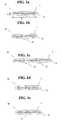
- Figs. 1a-1mpresent diagrams representing preferred cross-sections of hoisting ropes, preferably for a passenger elevator, according to different embodiments of the invention as seen from the lengthwise direction of the ropes.
- the rope (10,20,30,40,50,60, 70,80,90,100,110,120) represented by Figs. 1a-1lhas a belt-like structure, in other words, the rope has, as measured in a first direction, which is perpendicular to the lengthwise direction of the rope, thickness t1 and, as measured in a second direction, which is perpendicular to the lengthwise direction of the rope and to the aforesaid first direction, width t2, this width t2 being substantially larger than the thickness t1.
- the width of the ropeis thus substantially larger than its thickness.
- the ropehas preferably but not necessarily at least one, preferably two broad and substantially even surfaces, which broad surface can be efficiently used as a force-transmitting surface utilizing friction or a positive contact, because in this way a large contact surface is obtained.
- the broad surfaceneed not be completely even, but it may be provided with grooves or protrusions or it may have a curved shape.
- the ropepreferably has a substantially uniform structure throughout its length, but not necessarily, because, if desirable, the cross-section can be arranged to be cyclically changing e.g. as a cogged structure.
- the rope (10,20,30,40,50,60,70,80, 90,100,110,120)comprises a load-bearing part (11, 21, 31, 41, 51, 61, 71, 81, 91, 101, 111, 121), which is made of a non-metallic fiber composite comprising carbon fibers or glass fibers, preferably carbon fibers, in a polymer matrix.
- the load-bearing part (or possibly load-bearing parts) and its fibersare oriented in the lengthwise direction of the rope, which is why the rope retains its structure at bending. Individual fibers are thus substantially oriented in the longitudinal direction of the rope. The fibers are thus oriented in the direction of the force when a tensile force is acting on the rope.
- the aforesaid reinforcing fibersare bound together by the aforesaid polymer matrix to form an integral load-bearing part.
- said load-bearing part(11, 21, 31, 41, 51, 61, 71, 81, 91, 101, 111, 121) is a unitary coherent elongated bar-shaped body.
- Said reinforcing fibersare long continuous fibers preferably oriented in the lengthwise direction of the rope and preferably extending throughout the length of the rope.
- Preferably as many of the fibersmost preferably substantially all of the reinforcing fibers of said load-bearing part are oriented in the lengthwise direction of the rope. In other words, preferably the reinforcing fibers are substantially mutually non-entangled.
- a load-bearing partis achieved whose cross-sectional structure continues as unchanged as possible throughout the entire length of the rope.
- Said reinforcing fibersare distributed as evenly as possible in the load-bearing part to ensure that the load-bearing part is as homogeneous as possible in the transverse direction of the rope.
- the bending direction of the ropes shown in figures 1a-1mwould be up or down in the figures.
- the rope 10 presented in Fig. 1acomprises a load-bearing composite part 11 having a rectangular shape in cross-section and surrounded by a polymer layer 1.
- the ropecan be formed without a polymer layer 1.
- the rope 20 presented in Fig. 1bcomprises two load-bearing composite parts 21 of rectangular cross-section placed side by side and surrounded by a polymer layer 1.
- the polymer layer 1comprises a protrusion 22 for guiding the rope, located halfway between the edges of a broad side of the rope 10, at the middle of the area between the parts 21.
- the ropemay also have more than two composite parts placed side by side in this manner, as illustrated in Fig. 1c .
- the rope 40 presented in Fig. 1dcomprises a number of load-bearing composite parts 41 of rectangular cross-sectional shape placed side by side in the widthwise direction of the belt and surrounded by a polymer layer 1.
- the load-bearing parts shown in the figureare somewhat larger in width than in thickness. Alternatively, they could be implemented as having a substantially square cross-sectional shape.
- the rope 50 presented in Fig. 1ecomprises a load-bearing composite part 51 of rectangular cross-sectional shape, with a wire 52 placed on either side of it, the composite part 51 and the wire 52 being surrounded by a polymer layer 1.
- the wire 52may be a rope or strand and is preferably made of shear-resistant material, such as metal.
- the wireis preferably at the same distance from the rope surface as the composite part 51 and preferably, but not necessarily spaced apart from the composite part.
- the protective metallic partcould also be in a different form, e.g. a metallic lath or grid which runs alongside the length of the composite part.
- the rope 60 presented in Fig.If comprises a load-bearing composite part 61 of rectangular cross-sectional shape surrounded by a polymer layer 1. Formed on a surface of the rope 60 is a wedging surface consisting of a plurality of wedge-shaped protrusions 62, which preferably form a continuous part of the polymer layer 1.
- the rope 70 presented in Fig. 1gcomprises a load-bearing composite part 71 of rectangular cross-sectional shape surrounded by a polymer layer 1.
- the edges of the ropecomprise swelled portions 72, which preferably form part of the polymer layer 1.
- the swelled portionsprovide the advantage of guarding the edges of the composite part e.g. against fraying.
- the rope 80 presented in Fig. 1hcomprises a number of load-bearing composite parts 81 of round cross-section surrounded by a polymer layer 1.
- the rope 90 presented in Fig. 1icomprises two load-bearing parts 91 of square cross-section placed side by side and surrounded by a polymer layer 1.
- the polymer layer 1comprises a groove 92 in the region between parts 91 to render the rope more pliable, so that the rope will readily conform e.g. to curved surfaces.
- the groovescan be used to guide the rope.
- the ropemay also have more than two composite parts placed side by side in this manner as illustrated in Fig. 1j .
- the rope 110 presented in Fig. 1kcomprises a load-bearing composite part 111 having a substantially square cross-sectional shape.
- the width of the load-bearing part 111is larger than its thickness in a transverse direction of the rope.
- the rope 110has been formed without at all using a polymer layer like that described in the preceding embodiments, so the load-bearing part 111 covers the entire cross-section of the rope.
- the rope 120 presented in Fig. 1lcomprises a load-bearing composite part 121 of substantially rectangular cross-sectional shape having rounded corners.
- the load-bearing part 121has a width larger than its thickness in a transverse direction of the rope and is covered by a thin polymer layer 1.
- the load-bearing part 121covers a main proportion of the cross-section of the rope 120.
- the polymer layer 1is very thin as compared to the thickness of the load-bearing part in the thickness-wise direction t1 of the rope.
- the rope 130 presented in Fig. 1mcomprises mutually adjacent load-bearing composite parts 131 of substantially rectangular cross-sectional shape having rounded corners.
- the load-bearing part 131has a width larger than its thickness in a transverse direction of the rope and is covered by a thin polymer layer 1.
- the load-bearing part 131covers a main proportion of the cross-section of the rope 130.
- the polymer layer 1is very thin as compared to the thickness of the load-bearing part in the thickness-wise direction t1 of the rope.
- the polymer layer 1is preferably less than 1.5 mm in thickness, most preferably about 1 mm.
- Each one of the above-described ropescomprises at least one integral load-bearing composite part (11, 21, 31, 41, 51, 61, 71, 81, 91, 101, 111, 121) containing synthetic reinforcing fibers embedded in a polymer matrix.
- the reinforcing fibersare most preferably continuous fibers. They are oriented substantially in the lengthwise direction of the rope, so that a tensile stress is automatically applied to the fibers in their lengthwise direction.
- the matrix surrounding the reinforcing fiberskeeps the fibers in substantially unchanging positions relative to each other. Being slightly elastic, the matrix serves as a means of equalizing the distribution of the force applied to the fibers and reduces inter-fiber contacts and internal wear of the rope, thus increasing the service life of the rope.
- Eventual longitudinal inter-fiber motionconsists in elastic shear exerted on the matrix, but the main effect occurring at bending consists in stretching of all materials of the composite part and not in relative motion between them.
- the reinforcing fibersmost preferably consist of carbon fiber, permitting characteristics such as good tensile stiffness, low-weight structure and good thermal properties to be achieved.
- a reinforcement suited for some usesis glass fiber reinforcement, which provides inter alia a better electric insulation. In this case, the rope has a somewhat lower tensile stiffness, so it is possible to use small-diameter drive sheaves.
- the composite matrixin which individual fibers are distributed as homogeneously as possible, most preferably consists of epoxy, which has a good adhesion to reinforcements and a good strength and behaves advantageously in combination with glass and carbon fiber.
- the composite part(10,20,30,40,50,60,70,80,90, 100,110,120) comprises about 60% carbon fiber and 40% epoxy.
- the ropemay comprise a polymer layer 1.
- the polymer layer 1preferably consists of elastomer, most preferably high-friction elastomer, such as e.g. polyurethane, so that the friction between the drive sheave and the rope will be sufficient for moving the rope.
- the table belowshows the advantageous properties of carbon fiber and glass fiber. They have good strength and stiffness properties while also having a good thermal resistance, which is important in elevators, because a poor thermal resistance may result in damage to the hoisting ropes or even in the ropes catching fire, which is a safety hazard.
- a good thermal conductivitycontributes inter alia to the transmission of frictional heat, thereby reducing excessive heating of the drive sheave or accumulation of heat in the rope elements.
- Fig. 2represents an elevator according to an embodiment of the invention in which a belt-like rope is utilized.
- the ropes A and Bare preferably, but not necessarily, implemented according to one of Figs. 1a-1l .
- a number of belt-like ropes A and B passing around the drive sheave 2are set one over the other against each other.
- the ropes A and Bare of belt-like design and rope A is set against the drive sheave 2 and rope B is set against rope A, so that the thickness of each belt-like rope A and B in the direction of the center axis of the drive sheave 2 is larger than in the radial direction of the drive sheave 2.
- the ropes A and B moving at different radiihave different speeds.
- the ropes A and B passing around a diverting pulley 4 mounted on the elevator car or counterweight 3are connected together by a chain 5, which compensates the speed difference between the ropes A and B moving at different speeds.
- the chainis passed around a freely rotating diverting pulley 4, so that, if necessary, the rope can move around the diverting pulley at a speed corresponding to the speed difference between the ropes A and B placed against the drive sheave.
- This compensationcan also be implemented in other ways than by using a chain. Instead of a chain, it is possible to use e.g. a belt or rope.
- Fig. 3presents a detail of the elevator according to Fig. 2 , depicted in the direction of section A-A.
- Supported on the drive sheaveare a number of mutually superimposed ropes A and B disposed mutually adjacently, each set of said mutually superimposed ropes comprising a number of belt-like ropes A and B.
- the mutually superimposed ropesare separated from the adjacent mutually superimposed ropes by a protrusion u provided on the surface of the drive sheave, said protrusion u preferably protruding from the surface of the drive sheave along the whole length of the circumference, so that the protrusion u guides the ropes.
- the mutually parallel protrusions u on the drive sheave 2thus form between them groove-shaped guide surfaces for the ropes A and B.
- the protrusions upreferably have a height reaching at least up to the level of the midline of the material thickness of the last one B of the mutually superimposed ropes as seen in sequence starting from the surface of the drive sheave 2.
- the elevator describedcan also be implemented in such manner that there are no mutually adjacent ropes but only mutually superimposed ropes A, B on the drive sheave. Disposing the ropes in a mutually superimposed manner enables a compact construction and permits the use of a drive sheave having a shorter dimension as measured in the axial direction.
- Fig. 4represents the rope system of an elevator according to an embodiment of the invention, wherein the rope 8 has been arranged using a layout of reverse bending type, i.e. a layout where the bending direction varies as the rope is moving from pulley 2 to pulley 7 and further to pulley 9.
- the rope span dis freely adjustable, because the variation in bending direction is not detrimental when a rope according to the invention is used, for the rope is non-braided, retains its structure at bending and is thin in the bending direction.
- the distance through which the rope remains in contact with the drive sheavemay be over 180 degrees, which is advantageous in respect of friction.
- the rope 8may be passed according to a known technology to the elevator car and/or counterweight and/or to an anchorage in the elevator shaft. This may be implemented e.g. in such manner that the rope continues from pulley 2 functioning as a drive sheave to the elevator car and from pulley 9 to the counterweight, or the other way round.
- the rope 8is preferably one of those presented in Figs. 1a-1l .
- Fig. 5is a diagrammatic representation of an embodiment of the elevator of the invention provided with a condition monitoring arrangement for monitoring the condition of the rope 213, particularly for monitoring the condition of the polymer coating surrounding the load-bearing part.
- the ropeis preferably of a type as illustrated above in one of Figs. 1a-1l and comprises an electrically conductive part, preferably a part containing carbon fiber.
- the condition monitoring arrangementcomprises a condition monitoring device 210 connected to the end of the rope 213, to the load-bearing part of the rope 213 at a point near its anchorage 216, said part being electrically conductive.
- the arrangementfurther comprises a conductor 212 connected to an electrically conductive, preferably metallic diverting pulley 211 guiding the rope 213 and also to the condition monitoring device 210.
- the condition monitoring device 210connects conductors 212 and 214 and has been arranged to produce a voltage between the conductors. As the electrically insulating polymer coating is wearing off, its insulating capacity is reduced. Finally, the electrically conductive parts inside the rope come into contact with the pulley 211, the circuit between the conductors 214 and 212 being thus closed.
- the condition monitoring device 210further comprises means for observing an electric property of the circuit formed by the conductors 212 and 214, the rope 213 and the pulley 211. These means may comprise e.g.
- the electric property to be observedmay be e.g. a change in the electric current flowing through the aforesaid circuit or in the resistance, or a change in the magnetic field or voltage.
- Fig. 6is a diagrammatic representation of an embodiment of the elevator of the invention provided with a condition monitoring arrangement for monitoring the condition of the rope 219, particularly for monitoring the condition of the load-bearing part.
- the rope 219is preferably of one of the types described above and comprises at least one electrically conductive part 217, 218, 220, 221, preferably a part containing carbon fiber.
- the condition monitoring arrangementcomprises a condition monitoring device 210 connected to the electrically conductive part of the rope, which preferably is a load-bearing part.
- the condition monitoring device 210comprises means, such as e.g.
- a voltage or current sourcefor transmitting an excitation signal into the load-bearing part of the rope 219 and means for detecting, from another point of the load-bearing part or from a part connected to it, a response signal responding to the transmitted signal.
- the condition monitoring deviceOn the basis of the response signal, preferably by comparing it to predetermined limit values by means of a processor, the condition monitoring device has been arranged to infer the condition of the load-bearing part in the area between the point of input of the excitation signal and the point of measurement of the response signal.
- the condition monitoring devicehas been arranged to activate an alarm if the response signal does not fall within a desired range of values.
- the response signalchanges when a change occurs in an electric property dependent on the condition of the load-bearing part of the rope, such as resistance or capacitance.
- a changeoccurs in an electric property dependent on the condition of the load-bearing part of the rope, such as resistance or capacitance.
- resistance increasing due to crackswill produce a change in the response signal, from which change it can be deduced that the load-bearing part is in a weak condition.
- thisis arranged as illustrated in Fig. 6 by having the condition monitoring device 210 placed at a first end of the rope 219 and connected to two load-bearing parts 217 and 218, which are connected at the second end of the rope 219 by conductors 222. With this arrangement, the condition of both parts 217, 218 can be monitored simultaneously.
- the disturbance caused by mutually adjacent load-bearing parts to each othercan be reduced by interconnecting non-adjacent load-bearing parts with conductors 222, preferably connecting every second part to each other and to the condition monitoring device 210.
- Fig. 7presents an embodiment of the elevator of the invention wherein the elevator rope system comprises one or more ropes 10,20,30,40,50,60,70,80,90,100,110,120.
- the first end of the rope 10,20,30,40,50,60,70,80,90,100,110,120,8is secured to the elevator car 3 and the second end to the counterweight 6.
- the ropeis moved by means of a drive sheave 2 supported on the building, the drive sheave being connected to a power source, such as e.g. an electric motor (not shown), imparting rotation to the drive sheave.
- the ropeis preferably of a construction as illustrated in one of Figs. 1a-1l .
- the elevatoris preferably a passenger elevator, which has been installed to travel in an elevator shaft S in the building.
- the elevator presented in Fig. 7can be utilized with certain modifications for different hoisting heights.
- An advantageous hoisting height range for the elevator presented in Fig. 7is over 100 meters, preferably over 150 meters, and still more preferably over 250 meters.
- the rope massesalready have a very great importance regarding energy efficiency and structures of the elevator. Consequently, the use of a rope according to the invention for moving the elevator car 3 of a high-rise elevator is particularly advantageous, because in elevators designed for large hoisting heights the rope masses have a particularly great effect.
- the hoisting height range for the elevator in Fig. 7is over 100 meters, it is preferable, but not strictly necessary, to provide the elevator with a compensating rope.
- the ropes describedare also well applicable for use in counterweighted elevators, e.g. passenger elevators in residential buildings, that have a hoisting height of over 30 m. In the case of such hoisting heights, compensating ropes have traditionally been necessary.
- the present inventionallows the mass of compensating ropes to be reduced or even eliminated altogether.
- the ropes described hereare even better applicable for use in elevators having a hoisting height of 30-80 meters, because in these elevators the need for a compensating rope can even be eliminated altogether.
- the hoisting heightis most preferably over 40 m, because in the case of such heights the need for a compensating rope is most critical, and below 80 m, in which height range, by using low-weight ropes, the elevator can, if desirable, still be implemented even without using compensating ropes at all.
- Fig. 7depicts only one rope, but preferably the counterweight and elevator car are connected together by a number of ropes.
- 'load-bearing part'refers to a rope element that carries a significant proportion of the load imposed on the rope in its longitudinal direction, e.g. of the load imposed on the rope by an elevator car and/or counterweight supported by the rope.
- the loadproduces in the load-bearing part a tension in the longitudinal direction of the rope, which tension is transmitted further in the longitudinal direction of the rope inside the load-bearing part in question.
- the load-bearing partcan e.g. transmit the longitudinal force imposed on the rope by the drive sheave to the counterweight and/or elevator car in order to move them. For example in Fig.
- the reinforcing fibers of the load-bearing part in the rope (10,20,30,40,50,60,70,80,90,100, 110,120,130,8,A,B) of the invention for a hoisting device, especially a rope for a passenger elevatorare preferably continuous fibers.
- the fibersare preferably long fibers, most preferably extending throughout the entire length of the rope. Therefore, the rope can be produced by coiling the reinforcing fibers from a continuous fiber tow, into which a polymer matrix is absorbed.
- Substantially all of the reinforcing fibers of the load-bearing part (11,21,31,41,51, 61,71,81,91,101,121)are preferably made of one and the same material.
- the reinforcing fibers in the load-bearing partare contained in a polymer matrix.
- a polymer matrixe.g. by immersing them during manufacture into polymer matrix material. Therefore, individual reinforcing fibers bound together by the polymer matrix have between them some polymer of the matrix.
- a large quantity of reinforcing fibers bound together and extending in the longitudinal direction of the ropeare distributed in the polymer matrix.
- the reinforcing fibersare preferably distributed substantially uniformly, i.e.
- the reinforcing fibers together with the matrixconstitute a load-bearing part, inside which no chafing relative motion takes place when the rope is being bent.
- individual reinforcing fibers in the load-bearing partare mainly surrounded by the polymer matrix, but fiber-fiber contacts may occur here and there because it is difficult to control the positions of individual fibers relative to each other during their simultaneous impregnation with polymer matrix, and, on the other hand, complete elimination of incidental fiber-fiber contacts is not an absolute necessity regarding the functionality of the invention. However, if their incidental occurrences are to be reduced, then it is possible to pre-coat individual reinforcing fibers so that they already have a polymer coating around them before the individual reinforcing fibers are bound together.
- individual reinforcing fibers of the load-bearing part(11, 21, 31, 41, 51, 61, 71, 81, 91, 101, 111, 121, 131) comprise polymer matrix material around them.
- the polymer matrixis thus placed immediately against the reinforcing fiber, although between them there may be a thin coating on the reinforcing fiber, e.g. a primer arranged on the surface of the reinforcing fiber during production to improve chemical adhesion to the matrix material.
- Individual reinforcing fibersare uniformly distributed in the load-bearing part (11, 21, 31, 41, 51, 61, 71, 81, 91, 101, 111, 121, 131) so that individual reinforcing fibers have some matrix polymer between them.
- the spaces between individual reinforcing fibers in the load-bearing partare filled with matrix polymer.
- Most preferably substantially all of the spaces between individual reinforcing fibers in the load-bearing partare filled with matrix polymer. In the inter-fiber areas there may appear pores, but it is preferable to minimize the number of these.
- the matrix of the load-bearing part(11, 21, 31, 41, 51, 61, 71, 81, 91, 101, 111, 121, 131) most preferably has hard material properties.
- a hard matrixhelps support the reinforcing fibers especially when the rope is being bent. At bending, the reinforcing fibers closest to the outer surface of the bent rope are subjected to tension whereas the carbon fibers closest to the inner surface are subjected to compression in their lengthwise direction. Compression tends to cause the reinforcing fibers to buckle.
- a hard material for the polymer matrixit is possible to prevent buckling of fibers, because a hard material can provide support for the fibers and thus prevent them from buckling and equalize tensions within the rope.
- a polymer matrixconsisting of a polymer that is hard, preferably other than elastomer (an example of elastomer: rubber) or similar elastically behaving or yielding material.
- the most preferable materialsare epoxy, polyester, phenolic plastic or vinyl ester.
- the polymer matrixis preferably so hard that its coefficient of elasticity (E) is over 2 GPa, most preferably over 2.5 GPa. In this case, the coefficient of elasticity is preferably in the range of 2.5-10 GPa, most preferably in the range of 2.5-3.5 GPa.
- Fig. 8presents within a circle a partial cross-section of the surface structure of the load-bearing part (as seen in the lengthwise direction of the rope), this cross-section showing the manner in which the reinforcing fibers in the load-bearing parts (11, 21, 31, 41, 51, 61, 71, 81, 91, 101, 111, 121, 131) described elsewhere in the application are preferably arranged in the polymer matrix.
- the figureshows how the reinforcing fibers F are distributed substantially uniformly in the polymer matrix M, which surrounds the fibers and adheres to the fibers.
- the polymer matrix Mfills the spaces between reinforcing fibers F and, consisting of coherent solid material, binds substantially all reinforcing fibers F in the matrix together.
- the polymer matrix Mis as described elsewhere in the application and may comprise, besides a basic polymer, additives for fine adjustment of the matrix properties.
- the polymer matrix Mpreferably consists of a hard elastomer.
- a rope as described in connection with one of Figs. 1a-1mis used as the hoisting rope of an elevator, particularly a passenger elevator.
- One of the advantages achievedis an improved energy efficiency of the elevator.
- at least one rope, but preferably a number of ropes of a construction such that the width of the rope is larger than its thickness in a transverse direction of the ropeare fitted to support and move an elevator car, said rope comprising a load-bearing part (11, 21, 31, 41, 51, 61, 71, 81, 91, 101, 111, 121, 131) made of a composite material, which composite material comprises reinforcing fibers, which consist of carbon fiber or glass fiber, in a polymer matrix.
- the hoisting ropeis most preferably secured by one end to the elevator car and by the other end to a counterweight in the manner described in connection with Fig. 7 , but it is applicable for use in elevators without counterweight as well.
- the rope describedis also applicable for use as a hoisting rope in an elevator with a 1:2 hoisting ratio.
- the rope (10,20,30,40,50,60,70,80,90, 100,110, 120,130,8,A,B)is particularly well suited for use as a hoisting rope in an elevator having a large hoisting height, preferably an elevator having a hoisting height of over 100 meters.
- the rope definedcan also be used to implement a new elevator without a compensating rope, or to convert an old elevator into one without a compensating rope.
- the proposed rope (10,20,30,40,50,60,70,80,90,100, 110,120,130,8,A,B)is well applicable for use in an elevator having a hoisting height of over 30 meters, preferably 30-80 meters, most preferably 40-80 meters, and implemented without a compensating rope.
- cross-sections described in the present applicationcan also be utilized in ropes in which the composite has been replaced with some other material, such as e.g. metal. It is likewise obvious that a rope comprising a straight composite load-bearing part may have some other cross-sectional shape than those described, e.g. a round or oval shape.
- the load-bearing part/parts (11,21,31,41,51,61,71,81,91) in the embodiments in Figs. 1a-1jcan be arranged to cover most of the cross-section of the rope.
- the sheath-like polymer layer 1 surrounding the load-bearing part/partsis made thinner as compared to the thickness of the load-bearing part in the thickness-wise direction t1 of the rope.
- belts of other typesit is possible to use belts of other types than those presented.
- both carbon fiber and glass fibercan be used in the same composite part if necessary.
- the thickness of the polymer layermay be different from that described. It is likewise obvious that the shear-resistant part could be used as an additional component with any other rope structure showed in this application. It is likewise obvious that the matrix polymer in which the reinforcing fibers are distributed may comprise - mixed in the basic matrix polymer, such as e.g. epoxy - auxiliary materials, such as e.g. reinforcements, fillers, colors, fire retardants, stabilizers or corresponding agents. It is also obvious that the fibers need not necessarily be round in cross-section, but they may have some other cross-sectional shape. It is further obvious that auxiliary materials, such as e.g. reinforcements, fillers, colors, fire retardants, stabilizers or corresponding agents, may be mixed in the basic polymer of the layer 1, e.g. in polyurethane.
Landscapes
- Lift-Guide Devices, And Elevator Ropes And Cables (AREA)
- Ropes Or Cables (AREA)
Description
- The present invention relates to a passenger elevator as defined in the preamble of
claim 1. - Elevator ropes are generally made by braiding from metallic wires or strands and have a substantially round cross-sectional shape. A problem with metallic ropes is, due to the material properties of metal, that they have a high weight and a large thickness in relation to their tensile strength and tensile stiffness. There are also prior-art belt-like elevator ropes which have a width larger than their thickness. Previously known are e.g. solutions in which the load-bearing part of a belt-like elevator hoisting rope consists of metal wires coated with a soft material that protects the wires and increases the friction between the belt and the drive sheave. Due to the metal wires, such a solution involves the problem of high weight. On the other hand, a solution described in specification
EP1640307 A2 proposes the use of aramid braids as the load-bearing part. A problem with aramid material is mediocre tensile stiffness and tensile strength. Moreover, the behavior of aramid at high temperatures is problematic and constitutes a safety hazard. A further problem with solutions based on a braided construction is that the braiding reduces the stiffness and strength of the rope. In addition, the separate fibers of the braiding can undergo movement relative to each other in connection with bending of the rope, the wear of the fibers being thus increased. Tensile stiffness and thermal stability are also a problem in the solution proposed by specificationPCT/FI97 /00823 - The
EP 1 561 719 A1US 2004/0083707 A1 as well as theUS 2003/0121729 A1 disclose a belt like elevator rope where twisted strands of organic fibers are used for the load bearing part of the rope. TheUS 2004/0110441 discloses a rope of aramid fibers which aramid fibers are reinforced by a second phase with a higher modulus of elasticity. TheEP 1 561 719claim 1. - An object of the present invention is, among others, to eliminate the above-mentioned, drawbacks of prior-art solutions. A specific object of the invention is to improve the roping of a hoisting machine, particularly a passenger elevator.
- The aim of the invention is to produce one or more the following ad-vantages , among others :
- A rope that is light in weight and has a high tensile strength and tensile stiffness relative to its weight is achieved.
- A rope having an improved thermal stability against high temperatures is achieved.
- A rope having a high thermal conductivity combined with a high operating temperature is achieved.
- A rope that has a simple belt-like construction and is simple to manufacture is achieved.
- A rope that comprises one straight load-bearing part or a plurality of parallel straight load-bearing parts is achieved, an advantageous behavior at bending being thus obtained.
- An elevator having low-weight ropes is achieved. The load-bearing capacity of the sling and counterweight can be reduced.
- An elevator and an elevator rope are achieved in which the masses and axle loads to be moved and accelerated are reduced.
- An elevator in which the hoisting ropes have a low weight vs. rope tension is achieved.
- An elevator and a rope are achieved wherein the amplitude of transverse vibration of the rope is reduced and its vibration frequency increased.
- An elevator is achieved in which so-called reverse-bending roping has a reduced effect towards shortening service life.
- An elevator and a rope with no discontinuity or cyclic properties of the rope are achieved, the elevator rope being therefore noiseless and advantageous in respect of vibration.
- A rope is achieved that has a good creep resistance, because it has a straight construction and its geometry remains substantially constant at bending.
- A rope having low internal wear is achieved. A rope having a good resistance to high temperature and a good thermal conductivity is achieved.
- A rope having a good resistance to shear is achieved.
- An elevator having a safe roping is achieved.
- A high-rise elevator is achieved whose energy consumption is lower than that of earlier elevators.
- In elevator systems, the rope of the invention can be used as a safe means of supporting and/or moving an elevator car, a counterweight or both. The rope of the invention is applicable for use both in elevators with counterweight and in elevators without counterweight. In addition, it can also be used in conjunction with other hoisting machines, e.g. as a crane hoisting rope. The low weight of the rope provides an advantage especially in acceleration situations, because the energy required by changes in the speed of the rope depends on its mass. The low weight further provides an advantage in rope systems requiring separate compensating ropes, be-cause the need for compensating ropes is reduced or eliminated altogether. The low weight also allows easier handling of the ropes.
- The passenger elevator according to the invention is characterized by what is disclosed in
claim 1. - Preferred embodiments of the invention are characterized by what is disclosed in the dependent claims. The features of different embodiments of the invention can be applied in connection with other embodiments within the scope of the basic inventive concept.
- According to the invention, the width of the hoisting rope for a hoisting machine is larger than its thickness in a transverse direction of the rope. The rope comprises a load-bearing part made of a composite material, which composite material comprises non-metallic reinforcing fibers in a polymer matrix, said reinforcing fibers consisting of carbon fiber or glass fiber. The structure and choice of material make it possible to achieve low-weight hoisting ropes having a thin construction in the bending direction, a good tensile stiffness and tensile strength and an improved thermal stability. In addition, the rope structure remains substantially unchanged at bending, which contributes towards a long service life.
- According to the invention, the coefficient of elasticity (E) of the polymer matrix is greater than 2 GPa, preferably greater than 2.5 GPa, more preferably in the range of 2.5-10 GPa, and most preferably in the range of 2.5-3.5 GPa.
- In an embodiment of the invention, the aforesaid reinforcing fibers are laid in a longitudinal direction of the rope, i.e. in a direction parallel to the longitudinal direction of the rope. Thus, forces are distributed on the fibers in the direction of the tensile force, and additionally the straight fibers be-have at bending in a more advantageous manner than do fibers arranged e.g. in a spiral or crosswise pattern. The load-bearing part, consisting of straight fibers bound together by the polymer matrix to form an integral element, retains its shape and structure well at bending.
- In an embodiment of the invention individual fibers are homogeneously distributed in the aforesaid matrix. In other words, the reinforcing fibers are substantially uniformly distributed in the said load-bearing part.
- In an embodiment of the invention, said reinforcing fibers are bound together as an integral load-bearing part by said polymer matrix.
- In an embodiment of the invention, said reinforcing fibers are continuous fibers laid in the lengthwise direction of the rope and preferably extending throughout the length of the rope .
- In an embodiment of the invention, said load-bearing part consists of straight reinforcing fibers parallel to the lengthwise direction of the rope and bound together by the polymer matrix to form an integral element.
- In an embodiment of the invention, substantially all of the reinforcing fibers of said load-bearing part extend in the lengthwise direction of the rope.
- In an embodiment of the invention, said load-bearing part is an integral elongated body. In other words, the structures forming the load-bearing part are in mutual contact. The fibers are bound in the matrix preferably by a chemical bond, preferably by hydrogen bonding and/or covalent bonding.
- In an embodiment of the invention, the structure of the rope continues as a substantially uniform structure throughout the length of the rope.
- In an embodiment of the invention, the structure of the load-bearing part continues as a substantially uniform structure throughout the length of the rope .
- In an embodiment of the invention, substantially all of the reinforcing fibers of said load-bearing part extend in the lengthwise direction of the rope. Thus, the reinforcing fibers extending in the longitudinal direction of the rope can be adapted to carry most of the load.
- In an embodiment of the invention, the polymer matrix of the rope consists of non-elastomeric material. Thus, a structure is achieved in which the matrix provides a substantial support for the reinforcing fibers . The advantages include a longer service life and the possibility of employing smaller bending radii.
- In an embodiment of the invention, the polymer matrix comprises epoxy, polyester, phenolic plastic or vinyl ester. These hard materials together with aforesaid reinforcing fibers lead to an advantageous material combination that provides i.a. an advantageous behavior of the rope at bending.
- In an embodiment of the invention, the load-bearing part is a stiff, unitary coherent elongated bar-shaped body which returns straight when free of external bending. For this reason also the rope behaves in this manner.
- In an embodiment of the invention, over 50% of the cross-sectional square area of the load-bearing part consists of said reinforcing fiber, preferably so that 50%-80% consists of said reinforcing fiber, more preferably so that 55%-70% consists of said reinforcing fiber, and most preferably so that about 60% of said area consists of reinforcing fiber and about 40% of matrix material. This allows advantageous strength properties to be achieved while the amount of matrix material is still sufficient to adequately surround the fibers bound together by it.
- In an embodiment of the invention, the reinforcing fibers together with the matrix material form an integral load-bearing part, inside which substantially no chafing relative motion be-tween fibers or between fibers and matrix takes place when the rope is being bent. The advantages include a long service life of the rope and advantageous behavior at bending.
- In an embodiment of the invention, the load-bearing part(s) covers/cover a main proportion of the cross-section of the rope. Thus, a main proportion of the rope structure participates in sup-porting the load. The compo-site material can also be easily molded into such a form.
- In an embodiment of the invention, the width of the load-bearing part of the rope is larger than its thickness in a transverse direction of the rope. The rope can therefore withstand bending with a small radius.
- In an embodiment of the invention, the rope comprises a number of afore-said load-bearing parts side by side. In this way, the liability to failure of the composite part can be reduced, because the width/thickness ratio of the rope can be increased without increasing the width/thickness ratio of an individual composite part too much.
- In an embodiment of the invention, the reinforcing fibers consist of carbon fiber. In this way, a light construction and a good tensile stiffness and tensile strength as well as good thermal properties are achieved.
- In an embodiment of the invention, the rope additionally comprises outside the composite part at least one metallic element, such as a wire, lath or metallic grid. This renders the belt less liable to damage by shear.
- In an embodiment of the invention, the aforesaid polymer matrix consists of epoxy.
- In an embodiment of the invention, the load-bearing part is surrounded by a polymer layer. The belt surface can thus be protected against mechanical wear and humidity, among other things. This also allows the frictional coefficient of the rope to be adjusted to a sufficient value. The polymer layer preferably consists of elastomer, most preferably high-friction elastomer, such as e.g. polyurethane.
- In an embodiment of the invention, the load-bearing part consists of the aforesaid polymer matrix, of the reinforcing fibers bound together by the polymer matrix, and of a coating that may be provided around the fibers, and of auxiliary materials possibly comprised within the polymer matrix.
- According to the invention, the elevator comprises a drive sheave, an elevator car and a rope system for moving the elevator car by means of the drive sheave, said rope system comprising at least one rope whose width is larger than its thickness in a transverse direction of the rope. The rope comprises a load-bearing part made of a composite material comprising reinforcing fibers in a polymer matrix. The said reinforcing fibers consist of carbon fiber or glass fiber. This provides the advantage that the elevator ropes are low-weight ropes and advantageous in respect of heat resistance. An energy efficient elevator is also thus achieved. An elevator can thus be implemented even without using any compensating ropes at all. If desirable, the elevator can be implemented using a small-diameter drive sheave. The elevator is also safe, reliable and simple and has a long service life.
- In an embodiment of the invention, said elevator rope is a hoisting device rope as described above.
- In an embodiment of the invention, the elevator has been arranged to move the elevator car and counterweight by means of said rope. The elevator rope is preferably connected to the counterweight and elevator car with a 1:1 hoisting ratio, but could alternatively be connected with a 2:1 hoisting ratio.
- In an embodiment of the invention, the elevator comprises a first belt-like rope or rope portion placed against a pulley, preferably the drive sheave, and a second belt-like rope or rope portion placed against the first rope or rope portion, and that the said ropes or rope portions are fitted on the circumference of the drive sheave one over the other as seen from the direction of the bending radius. The ropes are thus set compactly on the pulley, allowing a small pulley to be used.
- In an embodiment of the invention, the elevator comprises a number of ropes fitted side by side and one over the other against the circumference of the drive sheave. The ropes are thus set compactly on the pulley.
- In an embodiment of the invention, the first rope or rope portion is connected to the second rope or rope portion placed against it by a chain, rope, belt or equivalent passed around a diverting pulley mounted on the elevator car and/or counterweight. This allows compensation of the speed difference between the hoisting ropes moving at different speeds.
- In an embodiment of the invention, the belt-like rope passes around a first diverting pulley, on which the rope is bent in a first bending direction, after which the rope passes around a second diverting pulley, on which the rope is bent in a second bending direction, this second bending direction being substantially opposite to the first bending direction. The rope span is thus freely adjustable, because changes in bending direction are less detrimental to a belt whose structure does not undergo any substantial change at bending. The properties of carbon fiber also contribute to the same effect.
- In an embodiment of the invention, the elevator has been implemented without compensating ropes. This is particularly advantageous in an elevator according to the invention in which the rope used in the rope system is of a design as defined above. The advantages include energy efficiency and a simple elevator construction. In this case it is preferable to provide the counterweight with bounce-limiting means.
- In an embodiment of the invention, the elevator is an elevator with counterweight, having a hoisting height of over 30 meters, preferably 30-80 meters, most preferably 40-80 meters, said elevator being implemented without compensating ropes. The elevator thus implemented is simpler than earlier elevators and yet energy efficient.
- In an embodiment of the invention, the elevator has a hoisting height of over 75 meters, preferably over 100 meters, more preferably over 150 meters, most preferably over 250 meters. The advantages of the invention are apparent especially in elevators having a large hoisting height, because normally in elevators with a large hoisting height the mass of the hoisting ropes constitutes most of the total mass to be moved. Therefore, when provided with a rope according to the present invention, an elevator having a large hoisting height is considerably more energy efficient than earlier elevators. An elevator thus implemented is also technically simpler, more material efficient and cheaper to manufacture, because e.g. the masses to be braked have been reduced. The effects of this are reflected on most of the structural components of the elevator regarding dimensioning. The invention is well applicable for use as a high-rise elevator or a mega high-rise elevator.
- In the use according to the invention, a hoisting device rope according to one of the above definitions is used as the hoisting rope of an elevator, especially a passenger elevator. One of the advantages is an improved energy efficiency of the elevator.
- In an embodiment of the invention, a hoisting device rope according to one of the above definitions is used as the hoisting rope of an elevator according to one of the above definitions. The rope is particularly well applicable for use in high-rise elevators and/or to reduce the need for a compensating rope.
- In the following, the invention will be described in detail by referring to embodiment examples and the attached drawings, wherein
Figs. 1a-1m are diagrammatic illustrations of the rope of the invention, each representing a different embodiment.Fig. 2 is a diagrammatic representation of an embodiment of the elevator of the invention.Fig. 3 represents a detail of the elevator inFig. 2 .Fig. 4 is a diagrammatic representation of an embodiment of the elevator of the invention.Fig. 5 is a diagrammatic representation of an embodiment of the elevator of the invention comprising a condition monitoring arrangement.Fig. 6 is a diagrammatic representation of an embodiment of the elevator of the invention comprising a condition monitoring arrangement.Fig. 7 is a diagrammatic representation of an embodiment of the elevator of the invention.Fig. 8 is a magnified diagrammatic representation of a detail of the cross-section of the rope of the invention.Figs. 1a-1m present diagrams representing preferred cross-sections of hoisting ropes, preferably for a passenger elevator, according to different embodiments of the invention as seen from the lengthwise direction of the ropes. The rope (10,20,30,40,50,60, 70,80,90,100,110,120) represented byFigs. 1a-1l has a belt-like structure, in other words, the rope has, as measured in a first direction, which is perpendicular to the lengthwise direction of the rope, thickness t1 and, as measured in a second direction, which is perpendicular to the lengthwise direction of the rope and to the aforesaid first direction, width t2, this width t2 being substantially larger than the thickness t1. The width of the rope is thus substantially larger than its thickness. Moreover, the rope has preferably but not necessarily at least one, preferably two broad and substantially even surfaces, which broad surface can be efficiently used as a force-transmitting surface utilizing friction or a positive contact, because in this way a large contact surface is obtained. The broad surface need not be completely even, but it may be provided with grooves or protrusions or it may have a curved shape. The rope preferably has a substantially uniform structure throughout its length, but not necessarily, because, if desirable, the cross-section can be arranged to be cyclically changing e.g. as a cogged structure. The rope (10,20,30,40,50,60,70,80, 90,100,110,120) comprises a load-bearing part (11, 21, 31, 41, 51, 61, 71, 81, 91, 101, 111, 121), which is made of a non-metallic fiber composite comprising carbon fibers or glass fibers, preferably carbon fibers, in a polymer matrix. The load-bearing part (or possibly load-bearing parts) and its fibers are oriented in the lengthwise direction of the rope, which is why the rope retains its structure at bending. Individual fibers are thus substantially oriented in the longitudinal direction of the rope. The fibers are thus oriented in the direction of the force when a tensile force is acting on the rope. The aforesaid reinforcing fibers are bound together by the aforesaid polymer matrix to form an integral load-bearing part. Thus, said load-bearing part (11, 21, 31, 41, 51, 61, 71, 81, 91, 101, 111, 121) is a unitary coherent elongated bar-shaped body. Said reinforcing fibers are long continuous fibers preferably oriented in the lengthwise direction of the rope and preferably extending throughout the length of the rope. Preferably as many of the fibers, most preferably substantially all of the reinforcing fibers of said load-bearing part are oriented in the lengthwise direction of the rope. In other words, preferably the reinforcing fibers are substantially mutually non-entangled. Thus, a load-bearing part is achieved whose cross-sectional structure continues as unchanged as possible throughout the entire length of the rope. Said reinforcing fibers are distributed as evenly as possible in the load-bearing part to ensure that the load-bearing part is as homogeneous as possible in the transverse direction of the rope. The bending direction of the ropes shown infigures 1a-1m would be up or down in the figures.- The
rope 10 presented inFig. 1a comprises a load-bearingcomposite part 11 having a rectangular shape in cross-section and surrounded by apolymer layer 1. Alternatively, the rope can be formed without apolymer layer 1. - The
rope 20 presented inFig. 1b comprises two load-bearingcomposite parts 21 of rectangular cross-section placed side by side and surrounded by apolymer layer 1. Thepolymer layer 1 comprises aprotrusion 22 for guiding the rope, located halfway between the edges of a broad side of therope 10, at the middle of the area between theparts 21. The rope may also have more than two composite parts placed side by side in this manner, as illustrated inFig. 1c . - The
rope 40 presented inFig. 1d comprises a number of load-bearingcomposite parts 41 of rectangular cross-sectional shape placed side by side in the widthwise direction of the belt and surrounded by apolymer layer 1. The load-bearing parts shown in the figure are somewhat larger in width than in thickness. Alternatively, they could be implemented as having a substantially square cross-sectional shape. - The
rope 50 presented inFig. 1e comprises a load-bearingcomposite part 51 of rectangular cross-sectional shape, with awire 52 placed on either side of it, thecomposite part 51 and thewire 52 being surrounded by apolymer layer 1. Thewire 52 may be a rope or strand and is preferably made of shear-resistant material, such as metal. The wire is preferably at the same distance from the rope surface as thecomposite part 51 and preferably, but not necessarily spaced apart from the composite part. However, the protective metallic part could also be in a different form, e.g. a metallic lath or grid which runs alongside the length of the composite part. - The
rope 60 presented in Fig. If comprises a load-bearingcomposite part 61 of rectangular cross-sectional shape surrounded by apolymer layer 1. Formed on a surface of therope 60 is a wedging surface consisting of a plurality of wedge-shapedprotrusions 62, which preferably form a continuous part of thepolymer layer 1. - The
rope 70 presented inFig. 1g comprises a load-bearingcomposite part 71 of rectangular cross-sectional shape surrounded by apolymer layer 1. The edges of the rope comprise swelledportions 72, which preferably form part of thepolymer layer 1. The swelled portions provide the advantage of guarding the edges of the composite part e.g. against fraying. - The
rope 80 presented inFig. 1h comprises a number of load-bearingcomposite parts 81 of round cross-section surrounded by apolymer layer 1. - The
rope 90 presented inFig. 1i comprises two load-bearing parts 91 of square cross-section placed side by side and surrounded by apolymer layer 1. Thepolymer layer 1 comprises a groove 92 in the region betweenparts 91 to render the rope more pliable, so that the rope will readily conform e.g. to curved surfaces. Alternatively, the grooves can be used to guide the rope. The rope may also have more than two composite parts placed side by side in this manner as illustrated inFig. 1j . - The
rope 110 presented inFig. 1k comprises a load-bearingcomposite part 111 having a substantially square cross-sectional shape. The width of the load-bearing part 111 is larger than its thickness in a transverse direction of the rope. Therope 110 has been formed without at all using a polymer layer like that described in the preceding embodiments, so the load-bearing part 111 covers the entire cross-section of the rope. - The
rope 120 presented inFig. 1l comprises a load-bearingcomposite part 121 of substantially rectangular cross-sectional shape having rounded corners. The load-bearing part 121 has a width larger than its thickness in a transverse direction of the rope and is covered by athin polymer layer 1. The load-bearing part 121 covers a main proportion of the cross-section of therope 120. Thepolymer layer 1 is very thin as compared to the thickness of the load-bearing part in the thickness-wise direction t1 of the rope. - The
rope 130 presented inFig. 1m comprises mutually adjacent load-bearingcomposite parts 131 of substantially rectangular cross-sectional shape having rounded corners. The load-bearing part 131 has a width larger than its thickness in a transverse direction of the rope and is covered by athin polymer layer 1. The load-bearing part 131 covers a main proportion of the cross-section of therope 130. Thepolymer layer 1 is very thin as compared to the thickness of the load-bearing part in the thickness-wise direction t1 of the rope. Thepolymer layer 1 is preferably less than 1.5 mm in thickness, most preferably about 1 mm. - Each one of the above-described ropes comprises at least one integral load-bearing composite part (11, 21, 31, 41, 51, 61, 71, 81, 91, 101, 111, 121) containing synthetic reinforcing fibers embedded in a polymer matrix. The reinforcing fibers are most preferably continuous fibers. They are oriented substantially in the lengthwise direction of the rope, so that a tensile stress is automatically applied to the fibers in their lengthwise direction. The matrix surrounding the reinforcing fibers keeps the fibers in substantially unchanging positions relative to each other. Being slightly elastic, the matrix serves as a means of equalizing the distribution of the force applied to the fibers and reduces inter-fiber contacts and internal wear of the rope, thus increasing the service life of the rope. Eventual longitudinal inter-fiber motion consists in elastic shear exerted on the matrix, but the main effect occurring at bending consists in stretching of all materials of the composite part and not in relative motion between them. The reinforcing fibers most preferably consist of carbon fiber, permitting characteristics such as good tensile stiffness, low-weight structure and good thermal properties to be achieved. Alternatively, a reinforcement suited for some uses is glass fiber reinforcement, which provides inter alia a better electric insulation. In this case, the rope has a somewhat lower tensile stiffness, so it is possible to use small-diameter drive sheaves. The composite matrix, in which individual fibers are distributed as homogeneously as possible, most preferably consists of epoxy, which has a good adhesion to reinforcements and a good strength and behaves advantageously in combination with glass and carbon fiber. Alternatively, it is possible to use e.g. polyester or vinyl ester. Most preferably the composite part (10,20,30,40,50,60,70,80,90, 100,110,120) comprises about 60% carbon fiber and 40% epoxy. As stated above, the rope may comprise a
polymer layer 1. Thepolymer layer 1 preferably consists of elastomer, most preferably high-friction elastomer, such as e.g. polyurethane, so that the friction between the drive sheave and the rope will be sufficient for moving the rope. - The table below shows the advantageous properties of carbon fiber and glass fiber. They have good strength and stiffness properties while also having a good thermal resistance, which is important in elevators, because a poor thermal resistance may result in damage to the hoisting ropes or even in the ropes catching fire, which is a safety hazard. A good thermal conductivity contributes inter alia to the transmission of frictional heat, thereby reducing excessive heating of the drive sheave or accumulation of heat in the rope elements.
Glass fiber Carbon fiber Aramid fiber Density kg/m3 2540 1820 1450 Strength N/mm2 3600 4500 3620 Stiffness N/mm2 75000 200000-600000 75000...120000 Softening temperature deg/C 850 >2000 450...500, carbonizing Thermal conductivity W/mK 0.8 105 0.05 Fig. 2 represents an elevator according to an embodiment of the invention in which a belt-like rope is utilized. The ropes A and B are preferably, but not necessarily, implemented according to one ofFigs. 1a-1l . A number of belt-like ropes A and B passing around thedrive sheave 2 are set one over the other against each other. The ropes A and B are of belt-like design and rope A is set against thedrive sheave 2 and rope B is set against rope A, so that the thickness of each belt-like rope A and B in the direction of the center axis of thedrive sheave 2 is larger than in the radial direction of thedrive sheave 2. The ropes A and B moving at different radii have different speeds. The ropes A and B passing around a diverting pulley 4 mounted on the elevator car orcounterweight 3 are connected together by achain 5, which compensates the speed difference between the ropes A and B moving at different speeds. The chain is passed around a freely rotating diverting pulley 4, so that, if necessary, the rope can move around the diverting pulley at a speed corresponding to the speed difference between the ropes A and B placed against the drive sheave. This compensation can also be implemented in other ways than by using a chain. Instead of a chain, it is possible to use e.g. a belt or rope. Alternatively, it is possible to omit thechain 5 and implement rope A and rope B depicted in the figure as a single continuous rope, which can be passed around the diverting pulley 4 and back up, so that a portion of the rope leans against another portion of the same rope leaning against the drive sheave. Ropes set one over the other can also be placed side by side on the drive sheave as illustrated inFig. 3 , thus allowing efficient space utilization. In addition, it is also possible to pass around the drive sheave more than two ropes one over the other.Fig. 3 presents a detail of the elevator according toFig. 2 , depicted in the direction of section A-A. Supported on the drive sheave are a number of mutually superimposed ropes A and B disposed mutually adjacently, each set of said mutually superimposed ropes comprising a number of belt-like ropes A and B. In the figure, the mutually superimposed ropes are separated from the adjacent mutually superimposed ropes by a protrusion u provided on the surface of the drive sheave, said protrusion u preferably protruding from the surface of the drive sheave along the whole length of the circumference, so that the protrusion u guides the ropes. The mutually parallel protrusions u on thedrive sheave 2 thus form between them groove-shaped guide surfaces for the ropes A and B. The protrusions u preferably have a height reaching at least up to the level of the midline of the material thickness of the last one B of the mutually superimposed ropes as seen in sequence starting from the surface of thedrive sheave 2. If desirable, it is naturally also possible to implement the drive sheave inFig. 3 without protrusions or with protrusions shaped differently. Of course, if desirable, the elevator described can also be implemented in such manner that there are no mutually adjacent ropes but only mutually superimposed ropes A, B on the drive sheave. Disposing the ropes in a mutually superimposed manner enables a compact construction and permits the use of a drive sheave having a shorter dimension as measured in the axial direction.Fig. 4 represents the rope system of an elevator according to an embodiment of the invention, wherein therope 8 has been arranged using a layout of reverse bending type, i.e. a layout where the bending direction varies as the rope is moving frompulley 2 topulley 7 and further to pulley 9. In this case, the rope span d is freely adjustable, because the variation in bending direction is not detrimental when a rope according to the invention is used, for the rope is non-braided, retains its structure at bending and is thin in the bending direction. At the same time, the distance through which the rope remains in contact with the drive sheave may be over 180 degrees, which is advantageous in respect of friction. The figure only shows a view of the roping in the region of the diverting pulleys. Frompulleys 2 and 9, therope 8 may be passed according to a known technology to the elevator car and/or counterweight and/or to an anchorage in the elevator shaft. This may be implemented e.g. in such manner that the rope continues frompulley 2 functioning as a drive sheave to the elevator car and from pulley 9 to the counterweight, or the other way round. In construction, therope 8 is preferably one of those presented inFigs. 1a-1l .Fig. 5 is a diagrammatic representation of an embodiment of the elevator of the invention provided with a condition monitoring arrangement for monitoring the condition of therope 213, particularly for monitoring the condition of the polymer coating surrounding the load-bearing part. The rope is preferably of a type as illustrated above in one ofFigs. 1a-1l and comprises an electrically conductive part, preferably a part containing carbon fiber. The condition monitoring arrangement comprises acondition monitoring device 210 connected to the end of therope 213, to the load-bearing part of therope 213 at a point near itsanchorage 216, said part being electrically conductive. The arrangement further comprises aconductor 212 connected to an electrically conductive, preferably metallic divertingpulley 211 guiding therope 213 and also to thecondition monitoring device 210. Thecondition monitoring device 210 connectsconductors pulley 211, the circuit between theconductors condition monitoring device 210 further comprises means for observing an electric property of the circuit formed by theconductors rope 213 and thepulley 211. These means may comprise e.g. a sensor and a processor, which, upon detecting a change in the electric property, activate an alarm about excessive rope wear. The electric property to be observed may be e.g. a change in the electric current flowing through the aforesaid circuit or in the resistance, or a change in the magnetic field or voltage.Fig. 6 is a diagrammatic representation of an embodiment of the elevator of the invention provided with a condition monitoring arrangement for monitoring the condition of therope 219, particularly for monitoring the condition of the load-bearing part. Therope 219 is preferably of one of the types described above and comprises at least one electricallyconductive part condition monitoring device 210 connected to the electrically conductive part of the rope, which preferably is a load-bearing part. Thecondition monitoring device 210 comprises means, such as e.g. a voltage or current source for transmitting an excitation signal into the load-bearing part of therope 219 and means for detecting, from another point of the load-bearing part or from a part connected to it, a response signal responding to the transmitted signal. On the basis of the response signal, preferably by comparing it to predetermined limit values by means of a processor, the condition monitoring device has been arranged to infer the condition of the load-bearing part in the area between the point of input of the excitation signal and the point of measurement of the response signal. The condition monitoring device has been arranged to activate an alarm if the response signal does not fall within a desired range of values. The response signal changes when a change occurs in an electric property dependent on the condition of the load-bearing part of the rope, such as resistance or capacitance. For example, resistance increasing due to cracks will produce a change in the response signal, from which change it can be deduced that the load-bearing part is in a weak condition. Preferably this is arranged as illustrated inFig. 6 by having thecondition monitoring device 210 placed at a first end of therope 219 and connected to two load-bearingparts rope 219 byconductors 222. With this arrangement, the condition of bothparts conductors 222, preferably connecting every second part to each other and to thecondition monitoring device 210.Fig. 7 presents an embodiment of the elevator of the invention wherein the elevator rope system comprises one ormore ropes rope elevator car 3 and the second end to thecounterweight 6. The rope is moved by means of adrive sheave 2 supported on the building, the drive sheave being connected to a power source, such as e.g. an electric motor (not shown), imparting rotation to the drive sheave. The rope is preferably of a construction as illustrated in one ofFigs. 1a-1l . The elevator is preferably a passenger elevator, which has been installed to travel in an elevator shaft S in the building. The elevator presented inFig. 7 can be utilized with certain modifications for different hoisting heights.- An advantageous hoisting height range for the elevator presented in
Fig. 7 is over 100 meters, preferably over 150 meters, and still more preferably over 250 meters. In elevators of this order of hoisting heights, the rope masses already have a very great importance regarding energy efficiency and structures of the elevator. Consequently, the use of a rope according to the invention for moving theelevator car 3 of a high-rise elevator is particularly advantageous, because in elevators designed for large hoisting heights the rope masses have a particularly great effect. Thus, it is possible to achieve, inter alia, a high-rise elevator having a reduced energy consumption. When the hoisting height range for the elevator inFig. 7 is over 100 meters, it is preferable, but not strictly necessary, to provide the elevator with a compensating rope. - The ropes described are also well applicable for use in counterweighted elevators, e.g. passenger elevators in residential buildings, that have a hoisting height of over 30 m. In the case of such hoisting heights, compensating ropes have traditionally been necessary. The present invention allows the mass of compensating ropes to be reduced or even eliminated altogether. In this respect, the ropes described here are even better applicable for use in elevators having a hoisting height of 30-80 meters, because in these elevators the need for a compensating rope can even be eliminated altogether. However, the hoisting height is most preferably over 40 m, because in the case of such heights the need for a compensating rope is most critical, and below 80 m, in which height range, by using low-weight ropes, the elevator can, if desirable, still be implemented even without using compensating ropes at all.
Fig. 7 depicts only one rope, but preferably the counterweight and elevator car are connected together by a number of ropes. - In the present application, 'load-bearing part' refers to a rope element that carries a significant proportion of the load imposed on the rope in its longitudinal direction, e.g. of the load imposed on the rope by an elevator car and/or counterweight supported by the rope. The load produces in the load-bearing part a tension in the longitudinal direction of the rope, which tension is transmitted further in the longitudinal direction of the rope inside the load-bearing part in question. Thus, the load-bearing part can e.g. transmit the longitudinal force imposed on the rope by the drive sheave to the counterweight and/or elevator car in order to move them. For example in
Fig. 7 , where thecounterweight 6 andelevator car 3 are supported by the rope (10,20,30,40,50,60,70,80,90,100,110,120), more precisely speaking by the load-bearing part in the rope, which load-bearing part extends from theelevator car 3 to thecounterweight 6. The rope (20,30,40,50,60,70,80,90,100, 110,120) is secured to the counterweight and to the elevator car. The tension produced by the weight of the counterweight/elevator car is transmitted from the securing point via the load-bearing part of the rope (10,20,30, 40,50,60,70,80,90,100,110,120) upwards from the counterweight/elevator car at least up to thedrive sheave 2. - As mentioned above, the reinforcing fibers of the load-bearing part in the rope (10,20,30,40,50,60,70,80,90,100, 110,120,130,8,A,B) of the invention for a hoisting device, especially a rope for a passenger elevator, are preferably continuous fibers. Thus the fibers are preferably long fibers, most preferably extending throughout the entire length of the rope. Therefore, the rope can be produced by coiling the reinforcing fibers from a continuous fiber tow, into which a polymer matrix is absorbed. Substantially all of the reinforcing fibers of the load-bearing part (11,21,31,41,51, 61,71,81,91,101,121) are preferably made of one and the same material.
- As explained above, the reinforcing fibers in the load-bearing part (11, 21, 31, 41, 51, 61, 71, 81, 91, 101, 111, 121) are contained in a polymer matrix. This means that, in the invention, individual reinforcing fibers are bound together by a polymer matrix, e.g. by immersing them during manufacture into polymer matrix material. Therefore, individual reinforcing fibers bound together by the polymer matrix have between them some polymer of the matrix. In the invention, a large quantity of reinforcing fibers bound together and extending in the longitudinal direction of the rope are distributed in the polymer matrix. The reinforcing fibers are preferably distributed substantially uniformly, i.e. homogeneously in the polymer matrix, so that the load-bearing part is as homogeneous as possible as observed in the direction of the cross-section of the rope. In other words, the fiber density in the cross-section of the load-bearing part thus does not vary greatly. The reinforcing fibers together with the matrix constitute a load-bearing part, inside which no chafing relative motion takes place when the rope is being bent. In the invention, individual reinforcing fibers in the load-bearing part (11, 21, 31, 41, 51, 61, 71, 81, 91, 101, 111, 121,131) are mainly surrounded by the polymer matrix, but fiber-fiber contacts may occur here and there because it is difficult to control the positions of individual fibers relative to each other during their simultaneous impregnation with polymer matrix, and, on the other hand, complete elimination of incidental fiber-fiber contacts is not an absolute necessity regarding the functionality of the invention. However, if their incidental occurrences are to be reduced, then it is possible to pre-coat individual reinforcing fibers so that they already have a polymer coating around them before the individual reinforcing fibers are bound together.
- In the invention, individual reinforcing fibers of the load-bearing part (11, 21, 31, 41, 51, 61, 71, 81, 91, 101, 111, 121, 131) comprise polymer matrix material around them. The polymer matrix is thus placed immediately against the reinforcing fiber, although between them there may be a thin coating on the reinforcing fiber, e.g. a primer arranged on the surface of the reinforcing fiber during production to improve chemical adhesion to the matrix material. Individual reinforcing fibers are uniformly distributed in the load-bearing part (11, 21, 31, 41, 51, 61, 71, 81, 91, 101, 111, 121, 131) so that individual reinforcing fibers have some matrix polymer between them. Preferably most of the spaces between individual reinforcing fibers in the load-bearing part are filled with matrix polymer. Most preferably substantially all of the spaces between individual reinforcing fibers in the load-bearing part are filled with matrix polymer. In the inter-fiber areas there may appear pores, but it is preferable to minimize the number of these.
- The matrix of the load-bearing part (11, 21, 31, 41, 51, 61, 71, 81, 91, 101, 111, 121, 131) most preferably has hard material properties. A hard matrix helps support the reinforcing fibers especially when the rope is being bent. At bending, the reinforcing fibers closest to the outer surface of the bent rope are subjected to tension whereas the carbon fibers closest to the inner surface are subjected to compression in their lengthwise direction. Compression tends to cause the reinforcing fibers to buckle. By selecting a hard material for the polymer matrix, it is possible to prevent buckling of fibers, because a hard material can provide support for the fibers and thus prevent them from buckling and equalize tensions within the rope. Thus it is preferable, inter alia to permit reduction of the bending radius of the rope, to use a polymer matrix consisting of a polymer that is hard, preferably other than elastomer (an example of elastomer: rubber) or similar elastically behaving or yielding material. The most preferable materials are epoxy, polyester, phenolic plastic or vinyl ester. The polymer matrix is preferably so hard that its coefficient of elasticity (E) is over 2 GPa, most preferably over 2.5 GPa. In this case, the coefficient of elasticity is preferably in the range of 2.5-10 GPa, most preferably in the range of 2.5-3.5 GPa.
Fig. 8 presents within a circle a partial cross-section of the surface structure of the load-bearing part (as seen in the lengthwise direction of the rope), this cross-section showing the manner in which the reinforcing fibers in the load-bearing parts (11, 21, 31, 41, 51, 61, 71, 81, 91, 101, 111, 121, 131) described elsewhere in the application are preferably arranged in the polymer matrix. The figure shows how the reinforcing fibers F are distributed substantially uniformly in the polymer matrix M, which surrounds the fibers and adheres to the fibers. The polymer matrix M fills the spaces between reinforcing fibers F and, consisting of coherent solid material, binds substantially all reinforcing fibers F in the matrix together. This prevents mutual chafing between reinforcing fibers F and chafing between matrix M and reinforcing fibers F. Between individual reinforcing fibers, preferably all the reinforcing fibers F and the matrix M there is a chemical bond, which provides the advantage of structural coherence, among other things. To strengthen the chemical bond, it is possible, but not necessary, to provide a coating (not shown) between the reinforcing fibers and the polymer matrix M. The polymer matrix M is as described elsewhere in the application and may comprise, besides a basic polymer, additives for fine adjustment of the matrix properties. The polymer matrix M preferably consists of a hard elastomer.- In the use according to the invention, a rope as described in connection with one of
Figs. 1a-1m is used as the hoisting rope of an elevator, particularly a passenger elevator. One of the advantages achieved is an improved energy efficiency of the elevator. In the use according to the invention, at least one rope, but preferably a number of ropes of a construction such that the width of the rope is larger than its thickness in a transverse direction of the rope are fitted to support and move an elevator car, said rope comprising a load-bearing part (11, 21, 31, 41, 51, 61, 71, 81, 91, 101, 111, 121, 131) made of a composite material, which composite material comprises reinforcing fibers, which consist of carbon fiber or glass fiber, in a polymer matrix. The hoisting rope is most preferably secured by one end to the elevator car and by the other end to a counterweight in the manner described in connection withFig. 7 , but it is applicable for use in elevators without counterweight as well. Although the figures only show elevators with a 1:1 hoisting ratio, the rope described is also applicable for use as a hoisting rope in an elevator with a 1:2 hoisting ratio. The rope (10,20,30,40,50,60,70,80,90, 100,110, 120,130,8,A,B) is particularly well suited for use as a hoisting rope in an elevator having a large hoisting height, preferably an elevator having a hoisting height of over 100 meters. The rope defined can also be used to implement a new elevator without a compensating rope, or to convert an old elevator into one without a compensating rope. The proposed rope (10,20,30,40,50,60,70,80,90,100, 110,120,130,8,A,B) is well applicable for use in an elevator having a hoisting height of over 30 meters, preferably 30-80 meters, most preferably 40-80 meters, and implemented without a compensating rope. - 'Implemented without a compensating rope' means that the counterweight and elevator car are not connected by a compensating rope. Still, even though there is no such specific compensating rope, it is possible that a car cable attached to the elevator car and especially arranged to be hanging between the elevator shaft and elevator car may participate in the compensation of the imbalance of the car rope masses. In the case of an elevator without a compensating rope, it is advantageous to provide the counterweight with means arranged to engage the counterweight guide rails in a counterweight bounce situation, which bounce situation can be detected by bounce monitoring means, e.g. from a decrease in the tension of the rope supporting the counterweight.
- It is obvious that the cross-sections described in the present application can also be utilized in ropes in which the composite has been replaced with some other material, such as e.g. metal. It is likewise obvious that a rope comprising a straight composite load-bearing part may have some other cross-sectional shape than those described, e.g. a round or oval shape.
- The advantages of the invention will be the more pronounced, the greater the hoisting height of the elevator. By utilizing ropes according to the invention, it is possible to achieve a mega-high-rise elevator having a hoisting height even as large as about 500 meters. Implementing hoisting heights of this order with prior-art ropes has been practically impossible or at least economically unreasonable. For example, if prior-art ropes in which the load-bearing part comprises metal braidings were used, the hoisting ropes would weigh up to tens of thousands of kilograms. Consequently, the mass of the hoisting ropes would be considerably greater than the payload.
- The invention has been described in the application from different points of view. Although substantially the same invention can be defined in different ways, entities defined by definitions starting from different points of view may slightly differ from each other and thus constitute separate inventions independently of each other.
- It is obvious to a person skilled in the art that the invention is not exclusively limited to the embodiments described above, in which the invention has been described by way of example, but that many variations and different embodiments of the invention are possible within the scope of the inventive concept defined in the claims presented below. Thus it is obvious that the ropes described may be provided with a cogged surface or some other type of patterned surface to produce a positive contact with the drive sheave. It is also obvious that the rectangular composite parts presented in
Figs. 1a-1l may comprise edges more starkly rounded than those illustrated or edges not rounded at all. Similarly, thepolymer layer 1 of the ropes may comprise edges/corners more starkly rounded than those illustrated or edges/corners not rounded at all. It is likewise obvious that the load-bearing part/parts (11,21,31,41,51,61,71,81,91) in the embodiments inFigs. 1a-1j can be arranged to cover most of the cross-section of the rope. In this case, the sheath-like polymer layer 1 surrounding the load-bearing part/parts is made thinner as compared to the thickness of the load-bearing part in the thickness-wise direction t1 of the rope. It is likewise obvious that, in conjunction with the solutions represented byFigs. 2, 3 and4 , it is possible to use belts of other types than those presented. It is likewise obvious that both carbon fiber and glass fiber can be used in the same composite part if necessary. It is likewise obvious that the thickness of the polymer layer may be different from that described. It is likewise obvious that the shear-resistant part could be used as an additional component with any other rope structure showed in this application. It is likewise obvious that the matrix polymer in which the reinforcing fibers are distributed may comprise - mixed in the basic matrix polymer, such as e.g. epoxy - auxiliary materials, such as e.g. reinforcements, fillers, colors, fire retardants, stabilizers or corresponding agents. It is also obvious that the fibers need not necessarily be round in cross-section, but they may have some other cross-sectional shape. It is further obvious that auxiliary materials, such as e.g. reinforcements, fillers, colors, fire retardants, stabilizers or corresponding agents, may be mixed in the basic polymer of thelayer 1, e.g. in polyurethane.
Claims (18)
- A passenger elevator, which comprises a drive sheave (2), a power source for rotating the drive sheave (2), an elevator car (3) and a rope system for moving the elevator car (3) by means of the drive sheave (2) via the friction between at least one rope (10,20,30,40,50,60,70,80,90,100,110,120, 8, A, B) of the rope system and the drive sheave, the width (t2) of the rope being larger than its thickness (tl) in a transverse direction of the rope, which rope (10,20,30,40,50,60,70,80, 90, 100,110,120, 8, A, B) comprises a load-bearing part (11,21,31,41,51,61,71,81,91,101,111,121,131) made of a composite material, said composite material comprising reinforcing fibers in a polymer matrix, said reinforcing fibers consisting of carbon fiber or glass fiber,characterized in that the coefficient of elasticity (E) of the polymer matrix (M) is over 2 GPa, preferably over 2.5 GPa, still more preferably in the range of 2.5-10GPa, and most preferably in the range of 2.5-3.5 GPa.
- Elevator according to claim 1, wherein said reinforcing fibers are oriented in the lengthwise direction of the rope.
- Elevator according to any one of the preceding claims, wherein individual fibers are homogeneously distributed in the aforesaid matrix.
- Elevator according to any one of the preceding claims, wherein said reinforcing fibers are continuous fibers oriented in the lengthwise direction of the rope and preferably extending throughout the entire length of the rope.
- Elevator according to any one of the preceding claims, wherein said reinforcing fibers are bound together as an integral load-bearing part by said polymer matrix, preferably at manufacturing stage by immersing the reinforcing fibers in polymer matrix material.
- Elevator according to any one of the preceding claims, wherein said load-bearing part (11, 21, 31, 41, 51, 61, 71, 81, 91, 101, 111, 121, 131) consists of straight reinforcing fibers parallel to the lengthwise direction of the rope and bound together by the polymer matrix to form an integral element.
- Elevator according to any one of the preceding claims, wherein the structure of the rope continues as a substantially uniform structure throughout the length of the rope.
- Elevator according to any one of the preceding claims, wherein the polymer matrix consists of non-elastomeric material.
- Elevator according to any one of the preceding claims, wherein the polymer matrix comprises epoxy, polyester, phenolic plastic or vinyl ester.
- Elevator according to any one of the preceding claims, wherein over 50% of the cross-sectional square area of the load-bearing part (11, 21, 31, 41, 51, 61, 71, 81, 91, 101, 111, 121, 131) consists of said reinforcing fiber, preferably so that 50%-80% consists of said reinforcing fiber, more preferably so that 55%-70% consists of said reinforcing fiber, most preferably so that about 60% of the square area consists of reinforcing fiber and about 40% of matrix material.
- Elevator according to any one of the preceding claims, wherein the width of the load-bearing part (11, 21, 31, 41, 51, 61, 71, 81, 91, 101, 111, 121, 131) is larger than its thickness in a transverse direction of the rope.
- Elevator according to any one of the preceding claims, wherein the rope comprises a number of aforesaid load-bearing parts (11, 21, 31, 41, 51, 61, 71, 81, 91, 101, 111, 121, 131) placed mutually adjacently.
- Elevator according to any one of the preceding claims, wherein the rope additionally comprises outside the composite part at least one metallic element (52), such as a wire, lath or metallic grid.
- Elevator according to any one of the preceding claims, wherein the load-bearing part (11, 21, 31, 41, 51, 61, 71, 81, 91, 101, 111, 121, 131) is surrounded by a polymer layer, which preferably consists of elastomer, most preferably high-friction elastomer, such as e.g. polyurethane.
- Elevator according to any one of the preceding claims, wherein the load-bearing part(s) (111, 121, 131) covers/cover a main proportion of the cross-section of the rope (110,120,130).
- Elevator according to any one of the preceding claims, wherein the load-bearing part consists of the aforesaid polymer matrix, of reinforcing fibers bound together by the polymer matrix, and possibly of a coating that may be provided around the fibers, and of auxiliary materials possibly comprised within the polymer matrix.
- Elevator according to any one of the preceding claims, wherein the structure of the rope (10,20,30,40,50,60,70,80, 90,100,110,120, 8, A, B) continues as a substantially uniform structure throughout the length of the rope and in that the rope comprises a broad and at least substantially even, preferably completely even, side surface so as to enable friction-based force-transmitting with the broad surface.
- Elevator according to any one of the preceding claims, wherein the rope is the hoisting rope of the elevator.
Priority Applications (1)
| Application Number | Priority Date | Filing Date | Title |
|---|---|---|---|
| EP21170722.9AEP3904265A1 (en) | 2008-01-18 | 2009-01-15 | Rope for a hoisting device, elevator and use |
Applications Claiming Priority (3)
| Application Number | Priority Date | Filing Date | Title |
|---|---|---|---|
| FI20080045AFI122261B (en) | 2008-01-18 | 2008-01-18 | Elevator |
| FI20080538AFI20080538A0 (en) | 2008-09-25 | 2008-09-25 | Lifting rope and lift |
| PCT/FI2009/000018WO2009090299A1 (en) | 2008-01-18 | 2009-01-15 | Rope for a hoisting machine, elevator and use |
Related Child Applications (2)
| Application Number | Title | Priority Date | Filing Date |
|---|---|---|---|
| EP21170722.9ADivisionEP3904265A1 (en) | 2008-01-18 | 2009-01-15 | Rope for a hoisting device, elevator and use |
| EP21170722.9ADivision-IntoEP3904265A1 (en) | 2008-01-18 | 2009-01-15 | Rope for a hoisting device, elevator and use |
Publications (3)
| Publication Number | Publication Date |
|---|---|
| EP2240395A1 EP2240395A1 (en) | 2010-10-20 |
| EP2240395A4 EP2240395A4 (en) | 2014-06-04 |
| EP2240395B1true EP2240395B1 (en) | 2021-07-14 |
Family
ID=40379537
Family Applications (2)
| Application Number | Title | Priority Date | Filing Date |
|---|---|---|---|
| EP21170722.9APendingEP3904265A1 (en) | 2008-01-18 | 2009-01-15 | Rope for a hoisting device, elevator and use |
| EP09702385.7AActiveEP2240395B1 (en) | 2008-01-18 | 2009-01-15 | Rope for a hoisting machine, elevator and use |
Family Applications Before (1)
| Application Number | Title | Priority Date | Filing Date |
|---|---|---|---|
| EP21170722.9APendingEP3904265A1 (en) | 2008-01-18 | 2009-01-15 | Rope for a hoisting device, elevator and use |
Country Status (12)
| Country | Link |
|---|---|
| US (4) | US9828214B2 (en) |
| EP (2) | EP3904265A1 (en) |
| JP (2) | JP5713682B2 (en) |
| KR (2) | KR101585516B1 (en) |
| CN (1) | CN101977834B (en) |
| AU (1) | AU2009204744B2 (en) |
| CA (2) | CA2914023C (en) |
| DE (1) | DE102009005093C5 (en) |
| EA (1) | EA019781B1 (en) |
| ES (1) | ES2882296T3 (en) |
| GB (1) | GB2458001B (en) |
| WO (1) | WO2009090299A1 (en) |
Families Citing this family (140)
| Publication number | Priority date | Publication date | Assignee | Title |
|---|---|---|---|---|
| ATE507180T1 (en)* | 2004-03-16 | 2011-05-15 | Otis Elevator Co | STRATEGIES FOR SUPPLYING ELECTRICAL SIGNALS TO MONITOR A CONDITION OF AN ELEVATOR LOAD |
| US9981415B2 (en) | 2007-09-10 | 2018-05-29 | Ehc Canada, Inc. | Method and apparatus for extrusion of thermoplastic handrail |
| US10350807B2 (en) | 2007-09-10 | 2019-07-16 | Ehc Canada, Inc. | Method and apparatus for extrusion of thermoplastic handrail |
| GB2458001B (en) | 2008-01-18 | 2010-12-08 | Kone Corp | An elevator hoist rope, an elevator and method |
| JP2011051736A (en)* | 2009-09-02 | 2011-03-17 | Toshiba Elevator Co Ltd | Elevator device |
| DE102009040964A1 (en)* | 2009-09-11 | 2011-03-24 | Sgl Carbon Se | rope |
| GB2474860A (en)* | 2009-10-28 | 2011-05-04 | Paradigm B V | Reelable support |
| FI125134B (en)* | 2010-04-12 | 2015-06-15 | Kone Corp | Elevator |
| US9944493B2 (en) | 2010-04-22 | 2018-04-17 | Thyssenkrupp Elevator Ag | Elevator suspension and transmission strip |
| FI125113B (en)* | 2010-04-30 | 2015-06-15 | Kone Corp | Elevator |
| FI20100223A0 (en)* | 2010-05-28 | 2010-05-28 | Kone Corp | Procedure and lift arrangement |
| EP2619121B1 (en)* | 2010-09-20 | 2024-12-18 | Otis Elevator Company | Tension member for an elevator having at least one traction surface comprising exposed weave fibers |
| DE102011002796A1 (en)* | 2011-01-17 | 2012-07-19 | Sgl Carbon Se | Carrier element for receiving in a train or Lastträgergurt |
| DE102011005323A1 (en) | 2011-03-10 | 2012-09-13 | Sgl Carbon Se | Process for the preparation of a tension-coated with a polymer layer tension carrier |
| DE102011005329A1 (en) | 2011-03-10 | 2012-09-13 | Sgl Carbon Se | Method and device for producing a fiber-reinforced composite material and in particular a tension member |
| CN102229397A (en)* | 2011-06-09 | 2011-11-02 | 上海微频莱机电科技有限公司 | Lifting device of tower cylinder lifter |
| AU2012283748B2 (en)* | 2011-07-08 | 2016-03-24 | Lb Wire Ropes Pty Limited | Improvements in cable stockings |
| ES2623364T3 (en)* | 2011-12-21 | 2017-07-11 | Kone Corporation | Elevator |
| FI124486B (en)* | 2012-01-24 | 2014-09-30 | Kone Corp | Line for an elevator device, liner arrangement, elevator and method for condition monitoring of the elevator device line |
| FI20125078L (en)* | 2012-01-25 | 2013-07-26 | Kone Corp | Elevator |
| US9796561B2 (en) | 2012-02-07 | 2017-10-24 | Otis Elevator Company | Wear detection for coated belt or rope |
| FI123534B (en)* | 2012-02-13 | 2013-06-28 | Kone Corp | Rope for a lifting device, elevator and method for making a rope |
| FI124582B (en)* | 2012-03-22 | 2014-10-31 | Kone Corp | Basket cable for a lift and lift |
| CN102635005A (en)* | 2012-04-18 | 2012-08-15 | 施凤鸣 | Special flat dragging tape for plastic-wrapping carbon fiber elevator |
| CN102635004B (en)* | 2012-04-18 | 2015-02-11 | 施凤鸣 | Plastic wrapped carbon fiber rope core specially used for elevator steel rope |
| CN102635003B (en)* | 2012-04-18 | 2015-02-25 | 施凤鸣 | Carbon fiber bilayer plastic wrapped steel rope specially used for elevator |
| KR102204494B1 (en)* | 2012-09-04 | 2021-01-20 | 데이진 아라미드 비.브이. | Method for non-destructive testing of synthetic ropes and rope suitable for use therein |
| FI125459B (en) | 2012-10-31 | 2015-10-15 | Kone Corp | Tightening system for a drive belt in a lift and elevator |
| EP2749519B1 (en) | 2012-12-27 | 2020-07-22 | KONE Corporation | Elevator with a non-metallic fibers belt-like ropes. |
| FI124542B (en)* | 2012-12-30 | 2014-10-15 | Kone Corp | Procedure and arrangement for monitoring the condition of lift lines |
| FI124543B (en)* | 2012-12-30 | 2014-10-15 | Kone Corp | Linen mount and lift |
| EP2767496B1 (en)* | 2013-02-14 | 2017-03-29 | KONE Corporation | An elevator |
| FI125572B (en)* | 2013-03-11 | 2015-11-30 | Exel Composites Oyj | Process for producing flexible composite bands or cords |
| PL2799217T3 (en)* | 2013-04-30 | 2015-08-31 | Kone Corp | A method for manufacturing a rope, a rope and an elevator |
| ES2549795T3 (en) | 2013-07-04 | 2015-11-02 | Kone Corporation | An elevator system |
| ES2564378T3 (en) | 2013-08-26 | 2016-03-22 | Kone Corporation | An elevator |
| JP2015048179A (en)* | 2013-08-30 | 2015-03-16 | 東芝エレベータ株式会社 | Elevator apparatus |
| EP2845832B1 (en) | 2013-09-05 | 2017-07-26 | KONE Corporation | A rope storage unit, a method for installing elevator and a method for fabricating rope storage unit |
| EP2851325B1 (en)* | 2013-09-24 | 2016-09-14 | KONE Corporation | A rope terminal assembly and an elevator |
| DE102013219825A1 (en)* | 2013-09-30 | 2015-04-02 | Thyssenkrupp Elevator Ag | elevator system |
| EP2860142B1 (en)* | 2013-10-10 | 2016-09-14 | KONE Corporation | A rope terminal assembly and an elevator |
| ES2609467T3 (en)* | 2013-10-10 | 2017-04-20 | Kone Corporation | Cable for a lifting and lifting device |
| WO2015058792A1 (en) | 2013-10-22 | 2015-04-30 | Kone Corporation | Method and device for checking the integrity of load bearing members of an elevator system |
| EP2868613B1 (en)* | 2013-11-05 | 2019-05-15 | KONE Corporation | An elevator |
| EP2878563B1 (en)* | 2013-11-29 | 2017-03-22 | KONE Corporation | A rope terminal assembly and an elevator |
| EP2886500B1 (en) | 2013-12-17 | 2021-06-16 | KONE Corporation | An elevator |
| CN103693536B (en)* | 2013-12-19 | 2016-08-03 | 永大电梯设备(中国)有限公司 | A kind of lift appliance hoist ropes |
| EP2894119B1 (en) | 2014-01-08 | 2016-04-06 | KONE Corporation | Rope for an elevator, elevator and method |
| AT515335A1 (en)* | 2014-01-30 | 2015-08-15 | Teufelberger Fiber Rope Gmbh | rope composite |
| RU2569650C1 (en)* | 2014-02-17 | 2015-11-27 | Борис Васильевич Накашидзе | Reinforcement rope |
| EP2910509B1 (en)* | 2014-02-19 | 2016-11-02 | KONE Corporation | Rope clamp for an elevator. |
| EP2913288A1 (en)* | 2014-02-28 | 2015-09-02 | Inventio AG | Support for an elevator |
| EP2921446A1 (en) | 2014-03-18 | 2015-09-23 | Kone Corporation | An elevator |
| CN104098008B (en)* | 2014-03-26 | 2017-01-25 | 永大电梯设备(中国)有限公司 | Machine-room-free elevator device |
| DE102014206326A1 (en)* | 2014-04-02 | 2015-10-08 | Contitech Antriebssysteme Gmbh | Support means for a conveyor, in particular carrying strap for elevators |
| CN106255657B (en)* | 2014-04-30 | 2020-03-03 | 三菱电机株式会社 | Elevator device and elevator spot inspection method |
| DE102014208223A1 (en)* | 2014-04-30 | 2015-11-05 | Contitech Antriebssysteme Gmbh | Drive or carrying strap with high tensile stiffness, especially for elevator technology |
| EP2952464B1 (en) | 2014-06-03 | 2019-05-01 | KONE Corporation | An elevator |
| FI126182B (en) | 2014-06-17 | 2016-07-29 | Kone Corp | Procedure and arrangement for monitoring the condition of a lift line |
| EP2985255B1 (en) | 2014-08-11 | 2021-11-17 | KONE Corporation | Elevator |
| EP2987758B1 (en) | 2014-08-18 | 2016-11-30 | KONE Corporation | Elevator |
| DE102014012189A1 (en)* | 2014-08-20 | 2016-02-25 | Arntz Beteiligungs Gmbh & Co. Kg | Power transmission belt |
| EP2990370B1 (en)* | 2014-09-01 | 2017-06-14 | KONE Corporation | Elevator |
| CN104261230A (en)* | 2014-09-11 | 2015-01-07 | 江南嘉捷电梯股份有限公司 | Elevator crosshead sheave device |
| EP3009390B1 (en) | 2014-10-16 | 2018-12-05 | KONE Corporation | Method for manufacturing a hoisting rope, hoisting rope and elevator using the same |
| EP3015413B1 (en)* | 2014-11-03 | 2017-08-09 | KONE Corporation | Hoisting rope and hoisting apparatus |
| EP3025999A1 (en)* | 2014-11-25 | 2016-06-01 | KONE Corporation | Arrangement and method for installing an elevator rope |
| EP3028979A1 (en) | 2014-12-01 | 2016-06-08 | KONE Corporation | Method for manufacturing an electrical contact arrangement and arrangement |
| EP3034449A1 (en) | 2014-12-17 | 2016-06-22 | KONE Corporation | Rope storage unit and method for installing elevator ropes |
| WO2016112277A1 (en) | 2015-01-09 | 2016-07-14 | Otis Elevator Company | Tension member for elevator system |
| EP3048076B1 (en) | 2015-01-21 | 2017-04-19 | KONE Corporation | A rope lifting tool and a rope lifting arrangement |
| AU2016209391A1 (en) | 2015-01-22 | 2017-07-20 | Neptune Research, Llc | Composite reinforcement systems and methods of manufacturing the same |
| EP3053867A1 (en) | 2015-02-03 | 2016-08-10 | KONE Corporation | Rope terminal arrangement, arrangement for condition monitoring of an elevator rope and elevator |
| EP3056461B1 (en) | 2015-02-12 | 2017-09-06 | Kone Corporation | Arrangement and elevator |
| KR101564194B1 (en)* | 2015-03-26 | 2015-10-29 | 현대엘리베이터주식회사 | Rope for an elevator |
| CN106044470B (en)* | 2015-04-10 | 2020-04-17 | 奥的斯电梯公司 | Load bearing member for elevator system |
| EP3093261B1 (en)* | 2015-05-07 | 2019-07-03 | Otis Elevator Company | Fire resistant coated steel belt |
| CA2984255C (en) | 2015-05-07 | 2023-02-14 | Ehc Canada, Inc. | Compact composite handrails with enhanced mechanical properties |
| DE102015213568A1 (en) | 2015-07-20 | 2017-01-26 | Sgl Carbon Se | Material with at least two-layered sheath |
| EP3141513B1 (en)* | 2015-09-08 | 2022-12-07 | Otis Elevator Company | Elevator tension member |
| CN108025890B (en) | 2015-09-14 | 2021-07-09 | 奥的斯电梯公司 | Woven elevator belt with multifunctional coating |
| US10001452B2 (en)* | 2015-11-13 | 2018-06-19 | Goodrich Corporation | Aircraft rescue hoist rope designed for continuous inspection |
| EP3176117A1 (en)* | 2015-12-03 | 2017-06-07 | KONE Corporation | Rope terminal device, rope terminal arrangement and elevator |
| EP3199482A1 (en) | 2016-02-01 | 2017-08-02 | Kone Corporation | Rope terminal device, rope terminal arrangement and elevator |
| US10556775B2 (en) | 2016-02-09 | 2020-02-11 | Otis Elevator Company | Surface construction of elevator belt |
| EP3205615A1 (en) | 2016-02-15 | 2017-08-16 | KONE Corporation | Elevator |
| KR20180121595A (en)* | 2016-03-09 | 2018-11-07 | 오티스 엘리베이터 컴파니 | Enhanced fabric elevator belts with improved internal abrasion resistance |
| CN116424993A (en) | 2016-03-15 | 2023-07-14 | 奥的斯电梯公司 | Load-bearing members including transverse layers |
| US10252884B2 (en) | 2016-04-05 | 2019-04-09 | Otis Elevator Company | Wirelessly powered elevator electronic safety device |
| EP3243785B1 (en)* | 2016-05-11 | 2021-04-07 | KONE Corporation | Rope, elevator arrangement and elevator |
| US10464249B2 (en) | 2016-07-22 | 2019-11-05 | Ehc Canada, Inc. | Articles having composite member for inhibiting longitudinal stretch |
| ES2732239T3 (en) | 2016-08-18 | 2019-11-21 | Kone Corp | Cable storage unit and installation procedure of an elevator cable |
| WO2018041931A1 (en)* | 2016-08-31 | 2018-03-08 | Inventio Ag | Chain link for a highly resilient conveyor chain of a moving walkway, an escalator or a lift |
| EP3309104B1 (en)* | 2016-10-14 | 2019-10-09 | KONE Corporation | Method for avoiding unwanted safety gear tripping in an elevator system, controller adapted to perform such a method, governor brake and elevator system each having such a controller |
| US10689230B2 (en)* | 2016-12-02 | 2020-06-23 | Otis Elevator Company | Elevator system suspension member termination with improved pressure distribution |
| AU2017268631B2 (en) | 2016-12-02 | 2023-09-28 | Otis Elevator Company | Overbraided non-metallic tension members |
| EP3336036B1 (en) | 2016-12-16 | 2021-02-03 | KONE Corporation | Method and arrangement for condition monitoring of a hoisting rope of a hoisting apparatus |
| KR102657801B1 (en)* | 2016-12-16 | 2024-04-17 | 오티스 엘리베이터 컴파니 | Elevator system suspension member |
| EP3339231A1 (en) | 2016-12-23 | 2018-06-27 | KONE Corporation | Connector for a hoisting rope of a hoisting apparatus |
| CN108248149A (en)* | 2016-12-29 | 2018-07-06 | 通力股份公司 | Elevator cage wall structure and the method for manufacturing elevator cage wall structure |
| JP6664518B2 (en) | 2017-01-10 | 2020-03-13 | 三菱電機株式会社 | Rope and elevator using the same |
| EP3348510A1 (en) | 2017-01-12 | 2018-07-18 | KONE Corporation | Terminating arrangement for a rope of a hoisting apparatus |
| US11111105B2 (en)* | 2017-01-26 | 2021-09-07 | Otis Elevator Company | Compliant shear layer for elevator termination |
| DE102017101646A1 (en) | 2017-01-27 | 2018-08-02 | Fatzer Ag Drahtseilfabrik | Longitudinal element, in particular for a tensile or suspension means |
| AU2018202598A1 (en)* | 2017-04-20 | 2018-11-08 | Otis Elevator Company | Tension member for elevator system belt |
| KR102623964B1 (en)* | 2017-04-20 | 2024-01-11 | 오티스 엘리베이터 컴파니 | Elevator system belt with fabric tension member |
| AU2018202597B2 (en) | 2017-04-20 | 2023-11-16 | Otis Elevator Company | Tension member for elevator system belt |
| AU2018202605B2 (en)* | 2017-04-20 | 2023-11-30 | Otis Elevator Company | Tension member for elevator system belt |
| AU2018202655B2 (en)* | 2017-04-20 | 2023-12-07 | Otis Elevator Company | Tension member for elevator system belt |
| WO2018198240A1 (en) | 2017-04-26 | 2018-11-01 | 三菱電機株式会社 | Elevator, suspension body therefor, and production method for suspension body |
| US10556776B2 (en) | 2017-05-23 | 2020-02-11 | Otis Elevator Company | Lightweight elevator traveling cable |
| US10549953B2 (en)* | 2017-07-17 | 2020-02-04 | Thyssenkrupp Elevator Ag | Elevator belt position tracking system |
| JP6533258B2 (en)* | 2017-08-15 | 2019-06-19 | ジャン ミンジョンJANG, Min Jeong | Elevator balance rope {Balancing Rope for Elevator} |
| US11274017B2 (en)* | 2017-08-25 | 2022-03-15 | Otis Elevator Company | Belt with self-extinguishing layer and method of making |
| US20190100408A1 (en)* | 2017-09-29 | 2019-04-04 | Otis Elevator Company | Rope deterioration detection |
| EP3470359B1 (en) | 2017-10-11 | 2021-08-18 | KONE Corporation | Rope wheel assembly, compensator and elevator arrangement |
| EP3483109B1 (en)* | 2017-11-10 | 2021-01-20 | Otis Elevator Company | Elevator system belt |
| EP3505482A1 (en)* | 2017-12-29 | 2019-07-03 | KONE Corporation | Method and arrangement for condition monitoring of a rope of a hoisting apparatus |
| US11584619B2 (en) | 2018-01-15 | 2023-02-21 | Otis Elevator Company | Reinforced jacket for belt |
| CN108382955A (en)* | 2018-01-30 | 2018-08-10 | 苏州妙文信息科技有限公司 | Hoisting rope for elevator and the elevator traction sheave for coordinating the drawing belt |
| EP3533745A1 (en) | 2018-03-01 | 2019-09-04 | KONE Corporation | Method and arrangement for installing an elevator hoisting rope |
| RU2709571C2 (en)* | 2018-04-05 | 2019-12-18 | Давид-Константинос Георгиос Накашидзе | Armature cable |
| US20190322488A1 (en)* | 2018-04-23 | 2019-10-24 | Otis Elevator Company | Health monitoring of elevator tension member |
| KR102058964B1 (en) | 2018-05-18 | 2019-12-24 | 현대엘리베이터주식회사 | Fabrication method of belt type rope |
| US11970368B2 (en)* | 2018-06-18 | 2024-04-30 | Otis Elevator Company | Elevator system belt |
| US11299370B2 (en) | 2018-06-29 | 2022-04-12 | Otis Elevator Company | Data transmission via elevator system tension member |
| US10858780B2 (en) | 2018-07-25 | 2020-12-08 | Otis Elevator Company | Composite elevator system tension member |
| US11591186B2 (en)* | 2018-08-06 | 2023-02-28 | Otis Elevator Company | Belt with layered load bearing elements |
| US11548763B2 (en) | 2018-08-10 | 2023-01-10 | Otis Elevator Company | Load bearing traction members and method |
| JP2022516605A (en)* | 2018-12-21 | 2022-03-01 | アンピックス パワー ベスローテン ベンノートシャップ | Rope for flight wind power generation system |
| US11655120B2 (en)* | 2019-06-28 | 2023-05-23 | Otis Elevator Company | Elevator load bearing member including a unidirectional weave |
| US11105103B2 (en) | 2019-10-04 | 2021-08-31 | Global Bmu Access Technologies, Llc | Portable davit |
| CN114599508B (en)* | 2019-11-08 | 2023-07-25 | 三菱电机株式会社 | Suspension body of elevator and elevator |
| EP3885302A1 (en) | 2020-03-26 | 2021-09-29 | KONE Corporation | Rope wheel, traction wheel, elevator drive machinery and elevator |
| JP7357803B2 (en) | 2020-08-27 | 2023-10-06 | 三菱電機株式会社 | Belt, its manufacturing method, and elevator |
| WO2022228662A1 (en) | 2021-04-28 | 2022-11-03 | Kone Corporation | Method for controlling elevator counterweight brake device and elevator |
| WO2022228661A1 (en) | 2021-04-28 | 2022-11-03 | Kone Corporation | Elevator |
| DE102022125721A1 (en) | 2022-10-05 | 2023-12-07 | Tk Elevator Innovation And Operations Gmbh | Drive train arrangement for a belt drive unit of an elevator system as well as a correspondingly designed shaft and its use |
| EP4450444A1 (en) | 2023-04-18 | 2024-10-23 | KONE Corporation | A method and a monitoring arrangement |
| WO2025040832A1 (en)* | 2023-08-18 | 2025-02-27 | Kone Corporation | An elevator arrangement and a method for constructing an elevator |
Citations (14)
| Publication number | Priority date | Publication date | Assignee | Title |
|---|---|---|---|---|
| DE8702678U1 (en)* | 1987-02-21 | 1987-06-11 | Salzgitter Maschinenbau Gmbh, 38259 Salzgitter | Conveyor rope |
| US4677818A (en)* | 1984-07-11 | 1987-07-07 | Toho Beslon Co., Ltd. | Composite rope and manufacture thereof |
| DE3813338A1 (en) | 1988-04-21 | 1989-11-02 | Lachmann Hans Peter Dr Ing | High tensile strength element for dynamically stressed elastic articles, production of such high tensile strength elements, and article provided with such elements |
| US4887422A (en)* | 1988-09-06 | 1989-12-19 | Amsted Industries Incorporated | Rope with fiber core and method of forming same |
| US5002823A (en)* | 1987-06-12 | 1991-03-26 | E. I. Du Pont De Nemours And Company | Reinforced composites having improved flex fatigue life |
| US5084221A (en)* | 1988-12-28 | 1992-01-28 | Ube-Nitto Kasei Co., Ltd. | Process for manufacturing a twisted frp structure |
| JPH09324376A (en) | 1996-06-04 | 1997-12-16 | Mitsubishi Chem Corp | Tensile material using continuous fiber |
| WO2001028896A1 (en) | 1999-10-18 | 2001-04-26 | Stork Screens B.V. | Endless belt made from fibre-reinforced plastics material |
| US6295799B1 (en)* | 1999-09-27 | 2001-10-02 | Otis Elevator Company | Tension member for an elevator |
| EP1428927A1 (en) | 2002-12-04 | 2004-06-16 | Inventio Ag | Reinforced synthetic cable for lifts |
| EP1561719A1 (en) | 2002-11-12 | 2005-08-10 | Mitsubishi Denki Kabushiki Kaisha | Rope for elevator and elevator equipment |
| EP1283776B1 (en) | 2000-05-15 | 2006-07-12 | ContiTech Antriebssysteme GmbH | Method for producing products from polymeric materials in which strengthening supports are embedded |
| WO2007050069A1 (en) | 2005-10-27 | 2007-05-03 | Otis Elevator Company | Elevator load bearing assembly having a jacket with multiple polymer compositions |
| WO2008110241A2 (en)* | 2007-03-12 | 2008-09-18 | Inventio Ag | Elevator system, carrying means for an elevator system, and method for the production of a carrying means |
Family Cites Families (68)
| Publication number | Priority date | Publication date | Assignee | Title |
|---|---|---|---|---|
| US1164115A (en)* | 1909-01-21 | 1915-12-14 | Charles O Pearson | Traction-elevator. |
| US1873828A (en)* | 1930-06-16 | 1932-08-23 | Westinghouse Elec Elevator Co | Snubber for elevators |
| US2107013A (en)* | 1936-02-21 | 1938-02-01 | Nucord Company | Belt |
| US2526324A (en)* | 1944-08-08 | 1950-10-17 | Lockheed Aircraft Corp | Power transmitting belt |
| GB1362513A (en)* | 1970-03-16 | 1974-08-07 | Teleflex Ltd | Cables and winching arrangements therefor |
| AU2468771A (en)* | 1971-01-26 | 1972-07-27 | British Ropes Limited | Improvements in or relating to friction winding gear |
| US3964952A (en)* | 1971-03-19 | 1976-06-22 | Commissariat A L'energie Atomique | Method of manufacture of composite materials consisting of carbon fibers and resin and materials manufactured in accordance with said method |
| US4041789A (en)* | 1975-12-18 | 1977-08-16 | The Goodyear Tire & Rubber Company | Belt drive including toothed belts and toothed pulleys of improved tooth configurations |
| JPS5453451A (en)* | 1977-10-06 | 1979-04-26 | Toshiba Corp | Emergency elevator cage stopping device |
| US4563391A (en)* | 1981-08-13 | 1986-01-07 | Henlan, Inc. | Ribbon rod for use in oil well apparatus |
| GB2162283A (en)* | 1984-07-26 | 1986-01-29 | Blacks Equip Ltd | Winding shaft for mine winders, hoists and lifts |
| DE3739654A1 (en)* | 1987-11-23 | 1989-06-01 | Freisl Paul Peter | Automatic brake device for cages |
| US5127783A (en)* | 1989-05-25 | 1992-07-07 | The B.F. Goodrich Company | Carbon/carbon composite fasteners |
| JPH03119188A (en)* | 1989-10-03 | 1991-05-21 | Mitsubishi Kasei Corp | Fiber-reinforced plastic composite material |
| US5080175A (en)* | 1990-03-15 | 1992-01-14 | Williams Jerry G | Use of composite rod-stiffened wireline cable for transporting well tool |
| FR2683591B1 (en)* | 1991-11-13 | 1993-12-31 | Institut Francais Petrole | MEASURING AND INTERVENTIONAL DEVICE IN A WELLBORE AND USE IN AN OIL WELL. |
| US5753369A (en)* | 1994-07-27 | 1998-05-19 | Mitsuboshi Belting Ltd. | Power transmission belt |
| WO1996007833A1 (en)* | 1994-09-02 | 1996-03-14 | Hino Jidosha Kogyo Kabushiki Kaisha | Drum brake |
| JP2001524060A (en) | 1996-12-30 | 2001-11-27 | コネ コーポレイション | Elevator rope equipment |
| AU7403798A (en) | 1996-12-30 | 1998-07-31 | Kone Oy | Elevator rope arrangement |
| US6401871B2 (en)* | 1998-02-26 | 2002-06-11 | Otis Elevator Company | Tension member for an elevator |
| US6138799A (en)* | 1998-09-30 | 2000-10-31 | Otis Elevator Company | Belt-climbing elevator having drive in counterweight |
| US6742769B2 (en)* | 1999-04-01 | 2004-06-01 | Otis Elevator Company | Elevator sheave for use with flat ropes |
| IL136332A (en)* | 1999-06-11 | 2005-06-19 | Inventio Ag | Synthetic fiber rope |
| JP2001019292A (en)* | 1999-06-25 | 2001-01-23 | Inventio Ag | Device and method to prevent vertical directional displacement and vertical directional vibration of load support means of vertical carrier device |
| CN1188567C (en) | 1999-08-26 | 2005-02-09 | 奥蒂斯电梯公司 | Tension member for elevator |
| JP3745963B2 (en)* | 2000-02-29 | 2006-02-15 | 三ツ星ベルト株式会社 | Power transmission belt and manufacturing method thereof |
| US6325184B1 (en)* | 2000-03-07 | 2001-12-04 | The Regents Of The University Of California | Gravity brake |
| US6776263B2 (en)* | 2000-05-19 | 2004-08-17 | Esw-Extel Systems Wedel Gesellschaft Fuer Austruestung Mbh | Elevator system for the vertical transport of loads in an aircraft |
| US6595883B1 (en)* | 2000-07-06 | 2003-07-22 | The Gates Corporation | V-belt for clutching drive applications |
| WO2002046082A1 (en)* | 2000-12-07 | 2002-06-13 | Mitsubishi Denki Kabushiki Kaisha | Elevator main rope elongation sensor |
| SK286814B6 (en)* | 2001-06-21 | 2009-06-05 | Kone Corporation | Elevator |
| KR20030028818A (en)* | 2001-06-29 | 2003-04-10 | 미쓰비시덴키 가부시키가이샤 | Emergency brake device of elevator |
| US6742627B2 (en)* | 2001-07-27 | 2004-06-01 | Otis Elevator Company | Elevator pressure traction arrangement |
| US20030121729A1 (en)* | 2002-01-02 | 2003-07-03 | Guenther Heinz | Lift belt and system |
| JP3921603B2 (en)* | 2002-01-18 | 2007-05-30 | ニッタ株式会社 | Elevator drive belt |
| JP2004001919A (en)* | 2002-05-30 | 2004-01-08 | Otis Elevator Co | Elevator device |
| DE10240988B4 (en)* | 2002-09-05 | 2014-02-27 | Inventio Ag | Elevator installation with a belt and pulley drive transmission arrangement |
| JP2004262651A (en)* | 2002-09-11 | 2004-09-24 | Inventio Ag | Elevator, maintenance method for elevator, method for updating elevator, and clamp device for elevator |
| JP4034629B2 (en)* | 2002-09-30 | 2008-01-16 | 東京製綱株式会社 | Hybrid rope |
| WO2004037702A1 (en)* | 2002-10-25 | 2004-05-06 | Mitsubishi Denki Kabushiki Kaisha | Rope for elevator |
| IL158256A (en)* | 2002-11-01 | 2010-02-17 | Inventio Ag | Rope of synthetic fibre |
| ZA200308847B (en)* | 2002-12-04 | 2005-01-26 | Inventio Ag | Reinforced synthetic cable for lifts |
| JP2004218099A (en)* | 2003-01-09 | 2004-08-05 | Bridgestone Corp | Rubber-coated cord and method for producing the same |
| JP4771434B2 (en)* | 2004-03-02 | 2011-09-14 | テクスティルマ アクチエンゲゼルシャフト | Rope-like structure |
| DE102004030722A1 (en)* | 2004-06-25 | 2006-01-19 | Contitech Antriebssysteme Gmbh | Flat belts for elevator systems provided with reinforcements |
| SG121957A1 (en) | 2004-10-26 | 2006-05-26 | Inventio Ag | Support means and lift for transporting a load by a support means |
| MY192706A (en)* | 2004-12-17 | 2022-09-02 | Inventio Ag | Lift installation with a braking device, and method for braking and holding a lift installation |
| KR100594658B1 (en)* | 2005-01-29 | 2006-06-30 | 엘에스전선 주식회사 | Fiber-reinforced plastic wire for tension line of overhead transmission line, manufacturing method thereof and overhead transmission line using same |
| US20100018810A1 (en)* | 2005-03-01 | 2010-01-28 | Mitsubishi Electric Corporation | Elevator apparatus |
| BRPI0601926B1 (en)* | 2005-06-17 | 2018-06-12 | Inventio Aktiengesellschaft | BRAKE PARACHUTE DEVICE |
| ES2443891T3 (en)* | 2005-11-14 | 2014-02-20 | Otis Elevator Company | Lift load support member that has a conversion coating on a tension member |
| US20080003430A1 (en)* | 2006-06-28 | 2008-01-03 | 3M Innovative Properties Company | Particulate-loaded polymer fibers and extrusion methods |
| TWI435970B (en)* | 2006-09-29 | 2014-05-01 | Inventio Ag | Flat-belt-like supporting and drive means with tensile carriers |
| US7891070B2 (en)* | 2007-04-14 | 2011-02-22 | Air Logistics Corporation | Method for handling elongate strength members |
| WO2009026730A1 (en)* | 2007-08-31 | 2009-03-05 | Brugg Kabel Ag | Tensile body for static and dynamic loads |
| GB2458001B (en) | 2008-01-18 | 2010-12-08 | Kone Corp | An elevator hoist rope, an elevator and method |
| EP2608950B1 (en)* | 2010-08-27 | 2015-12-02 | SGL Carbon SE | Pulling system |
| CN202670972U (en)* | 2012-04-06 | 2013-01-16 | 东南电梯股份有限公司 | Up-down straight separated type fireproof door device of service lift |
| EP2767496B1 (en)* | 2013-02-14 | 2017-03-29 | KONE Corporation | An elevator |
| ES2549795T3 (en)* | 2013-07-04 | 2015-11-02 | Kone Corporation | An elevator system |
| ES2609467T3 (en)* | 2013-10-10 | 2017-04-20 | Kone Corporation | Cable for a lifting and lifting device |
| EP2868613B1 (en)* | 2013-11-05 | 2019-05-15 | KONE Corporation | An elevator |
| DE102014208223A1 (en)* | 2014-04-30 | 2015-11-05 | Contitech Antriebssysteme Gmbh | Drive or carrying strap with high tensile stiffness, especially for elevator technology |
| EP3141513B1 (en)* | 2015-09-08 | 2022-12-07 | Otis Elevator Company | Elevator tension member |
| CN105672009A (en)* | 2016-04-12 | 2016-06-15 | 日立电梯(中国)有限公司 | Elevator traction belt and elevator |
| US10689230B2 (en)* | 2016-12-02 | 2020-06-23 | Otis Elevator Company | Elevator system suspension member termination with improved pressure distribution |
| WO2018198240A1 (en)* | 2017-04-26 | 2018-11-01 | 三菱電機株式会社 | Elevator, suspension body therefor, and production method for suspension body |
- 2009
- 2009-01-14GBGB0900550Apatent/GB2458001B/enactiveActive
- 2009-01-15ESES09702385Tpatent/ES2882296T3/enactiveActive
- 2009-01-15EPEP21170722.9Apatent/EP3904265A1/enactivePending
- 2009-01-15CACA2914023Apatent/CA2914023C/enactiveActive
- 2009-01-15KRKR1020107016013Apatent/KR101585516B1/enactiveActive
- 2009-01-15AUAU2009204744Apatent/AU2009204744B2/enactiveActive
- 2009-01-15WOPCT/FI2009/000018patent/WO2009090299A1/enactiveApplication Filing
- 2009-01-15JPJP2010542655Apatent/JP5713682B2/ennot_activeExpired - Fee Related
- 2009-01-15EPEP09702385.7Apatent/EP2240395B1/enactiveActive
- 2009-01-15CACA2711074Apatent/CA2711074C/enactiveActive
- 2009-01-15EAEA201001018Apatent/EA019781B1/enunknown
- 2009-01-15CNCN200980109878.6Apatent/CN101977834B/enactiveActive
- 2009-01-15KRKR1020157007252Apatent/KR101714696B1/enactiveActive
- 2009-01-19DEDE102009005093.0Apatent/DE102009005093C5/enactiveActive
- 2010
- 2010-07-16USUS12/838,156patent/US9828214B2/enactiveActive
- 2011
- 2011-07-14USUS13/183,229patent/US20110266097A1/ennot_activeAbandoned
- 2014
- 2014-10-23JPJP2014216272Apatent/JP6109804B2/enactiveActive
- 2017
- 2017-10-27USUS15/796,360patent/US10843900B2/enactiveActive
- 2020
- 2020-09-30USUS17/039,315patent/US11565912B2/enactiveActive
Patent Citations (16)
| Publication number | Priority date | Publication date | Assignee | Title |
|---|---|---|---|---|
| US4677818A (en)* | 1984-07-11 | 1987-07-07 | Toho Beslon Co., Ltd. | Composite rope and manufacture thereof |
| DE8702678U1 (en)* | 1987-02-21 | 1987-06-11 | Salzgitter Maschinenbau Gmbh, 38259 Salzgitter | Conveyor rope |
| US5002823A (en)* | 1987-06-12 | 1991-03-26 | E. I. Du Pont De Nemours And Company | Reinforced composites having improved flex fatigue life |
| DE3813338A1 (en) | 1988-04-21 | 1989-11-02 | Lachmann Hans Peter Dr Ing | High tensile strength element for dynamically stressed elastic articles, production of such high tensile strength elements, and article provided with such elements |
| US4887422A (en)* | 1988-09-06 | 1989-12-19 | Amsted Industries Incorporated | Rope with fiber core and method of forming same |
| US5084221A (en)* | 1988-12-28 | 1992-01-28 | Ube-Nitto Kasei Co., Ltd. | Process for manufacturing a twisted frp structure |
| JPH09324376A (en) | 1996-06-04 | 1997-12-16 | Mitsubishi Chem Corp | Tensile material using continuous fiber |
| US6295799B1 (en)* | 1999-09-27 | 2001-10-02 | Otis Elevator Company | Tension member for an elevator |
| WO2001028896A1 (en) | 1999-10-18 | 2001-04-26 | Stork Screens B.V. | Endless belt made from fibre-reinforced plastics material |
| EP1283776B1 (en) | 2000-05-15 | 2006-07-12 | ContiTech Antriebssysteme GmbH | Method for producing products from polymeric materials in which strengthening supports are embedded |
| EP1561719A1 (en) | 2002-11-12 | 2005-08-10 | Mitsubishi Denki Kabushiki Kaisha | Rope for elevator and elevator equipment |
| EP1428927A1 (en) | 2002-12-04 | 2004-06-16 | Inventio Ag | Reinforced synthetic cable for lifts |
| WO2007050069A1 (en) | 2005-10-27 | 2007-05-03 | Otis Elevator Company | Elevator load bearing assembly having a jacket with multiple polymer compositions |
| WO2008110241A2 (en)* | 2007-03-12 | 2008-09-18 | Inventio Ag | Elevator system, carrying means for an elevator system, and method for the production of a carrying means |
| EP2125594A2 (en)* | 2007-03-12 | 2009-12-02 | Inventio Ag | Elevator system, carrying means for an elevator system, and method for the production of a carrying means |
| US20100133046A1 (en)* | 2007-03-12 | 2010-06-03 | Inventio Ag | Elevator system, suspension element for an elevator system, and device for manufacturing a suspension element |
Non-Patent Citations (7)
| Title |
|---|
| "Modern Plastics Handbook", 1 January 2000, MCGRAW-HILL, article HARPER CHARLES A., WASHINGTON FRANCISCO, AUCKLAND D C, CARACAS BOGOTÁ, LONDON LISBON, MEXICO MADRID, MILAN CITY, NEW MONTREAL, S: "Chapter 2: Thermosets, Reinforced Plastics, and Composites", XP055915701 |
| "Polymer Data Handbook", 1 January 1999, OXFORD UNIVERSITY PRESS, article SHELLEY MEE Y.: "Epoxy resins", pages: 90 - 96, XP055915691 |
| "Polymer Data Handbook", 1 January 1999, OXFORD UNIVERSITY PRESS, article VIERS BRENT D: "Kevlar", pages: 140 - 157, XP055915685 |
| ANONMOUS: "Vinyl Ester Sheet Molding Compound", MATWEB, Retrieved from the Internet <URL:https://www.matweb.com/search/datasheet.aspx?matguid=7ac4c12f06fe4ac19a437f4ef6a11bf8> |
| ANONYMOUS: "Overview of materials for Polyester (Thermoset)", MATWEB, Retrieved from the Internet <URL:https://www.matweb.com/search/datasheet.aspx?matguid=1d92ed366503454ba49b8a44099f90de&n=1&ckck=1> |
| GUNDUZ GUNGOR, EROL DEMET, AKKAS NURI: "Mechanical Properties of Unsaturated Polyester-Isocyanate Hybrid Polymer Network and Its E-Glass Fiber-reinforced Composite", JOURNAL OF COMPOSITE MATERIALS, SAGE PUBLICATIONS, USA, vol. 39, no. 17, 1 September 2005 (2005-09-01), USA , pages 1577 - 1589, XP055915679, ISSN: 0021-9983, DOI: 10.1177/0021998305051086 |
| W. BEITZ UND K.-H.GROTE: "Taschenbuch für den Maschinenbau 19.Auflage", 31 December 1997, SPRINGER VERLAG, Germany, ISBN: 3-540-62467-8* |
Also Published As
Similar Documents
| Publication | Publication Date | Title |
|---|---|---|
| US11565912B2 (en) | Rope for a hoisting device, elevator and use | |
| CN104203792B (en) | The operation cable and elevator of elevator | |
| RU2430207C2 (en) | Rope of synthetic fibres and lift device with such rope from synthetic fibres | |
| EP2563704B1 (en) | Elevator | |
| EP3392183B1 (en) | Tension member for elevator system belt | |
| WO2011004071A2 (en) | Rope of a hoisting apparatus, rope arrangement, elevator and method | |
| AU2006202277B2 (en) | Support means with connection, able to accept shearing force, for connecting several cables | |
| HK1200427A1 (en) | An elevator | |
| US20060272846A1 (en) | Support Means with Mechanically Positive Connection for Connecting Several Cables | |
| AU2015264789B2 (en) | Rope for a hoisting machine, elevator and use | |
| JP7613475B2 (en) | Ropes, rope structures | |
| JP7357803B2 (en) | Belt, its manufacturing method, and elevator | |
| CN117203147A (en) | Elevator with a motor | |
| CN116507574B (en) | Composite stranded wire and method for manufacturing same, rope, belt and elevator | |
| HK1204782B (en) | Travelling cable of an elevator, and an elevator |
Legal Events
| Date | Code | Title | Description |
|---|---|---|---|
| PUAI | Public reference made under article 153(3) epc to a published international application that has entered the european phase | Free format text:ORIGINAL CODE: 0009012 | |
| 17P | Request for examination filed | Effective date:20100805 | |
| AK | Designated contracting states | Kind code of ref document:A1 Designated state(s):AT BE BG CH CY CZ DE DK EE ES FI FR GB GR HR HU IE IS IT LI LT LU LV MC MK MT NL NO PL PT RO SE SI SK TR | |
| AX | Request for extension of the european patent | Extension state:AL BA RS | |
| DAX | Request for extension of the european patent (deleted) | ||
| A4 | Supplementary search report drawn up and despatched | Effective date:20140506 | |
| RIC1 | Information provided on ipc code assigned before grant | Ipc:D07B 1/04 20060101ALI20140428BHEP Ipc:D07B 5/10 20060101ALI20140428BHEP Ipc:B66B 7/06 20060101AFI20140428BHEP Ipc:D07B 1/22 20060101ALI20140428BHEP | |
| 17Q | First examination report despatched | Effective date:20150720 | |
| TPAC | Observations filed by third parties | Free format text:ORIGINAL CODE: EPIDOSNTIPA | |
| STAA | Information on the status of an ep patent application or granted ep patent | Free format text:STATUS: EXAMINATION IS IN PROGRESS | |
| GRAP | Despatch of communication of intention to grant a patent | Free format text:ORIGINAL CODE: EPIDOSNIGR1 | |
| STAA | Information on the status of an ep patent application or granted ep patent | Free format text:STATUS: GRANT OF PATENT IS INTENDED | |
| INTG | Intention to grant announced | Effective date:20201111 | |
| GRAJ | Information related to disapproval of communication of intention to grant by the applicant or resumption of examination proceedings by the epo deleted | Free format text:ORIGINAL CODE: EPIDOSDIGR1 | |
| STAA | Information on the status of an ep patent application or granted ep patent | Free format text:STATUS: EXAMINATION IS IN PROGRESS | |
| INTC | Intention to grant announced (deleted) | ||
| GRAP | Despatch of communication of intention to grant a patent | Free format text:ORIGINAL CODE: EPIDOSNIGR1 | |
| STAA | Information on the status of an ep patent application or granted ep patent | Free format text:STATUS: GRANT OF PATENT IS INTENDED | |
| RIC1 | Information provided on ipc code assigned before grant | Ipc:B66B 7/06 20060101AFI20210208BHEP Ipc:D07B 1/04 20060101ALI20210208BHEP Ipc:D07B 1/14 20060101ALI20210208BHEP Ipc:D07B 5/10 20060101ALI20210208BHEP Ipc:D07B 1/22 20060101ALI20210208BHEP | |
| INTG | Intention to grant announced | Effective date:20210301 | |
| GRAS | Grant fee paid | Free format text:ORIGINAL CODE: EPIDOSNIGR3 | |
| GRAA | (expected) grant | Free format text:ORIGINAL CODE: 0009210 | |
| STAA | Information on the status of an ep patent application or granted ep patent | Free format text:STATUS: THE PATENT HAS BEEN GRANTED | |
| AK | Designated contracting states | Kind code of ref document:B1 Designated state(s):AT BE BG CH CY CZ DE DK EE ES FI FR GB GR HR HU IE IS IT LI LT LU LV MC MK MT NL NO PL PT RO SE SI SK TR | |
| REG | Reference to a national code | Ref country code:GB Ref legal event code:FG4D | |
| REG | Reference to a national code | Ref country code:DE Ref legal event code:R096 Ref document number:602009063875 Country of ref document:DE | |
| REG | Reference to a national code | Ref country code:IE Ref legal event code:FG4D | |
| REG | Reference to a national code | Ref country code:AT Ref legal event code:REF Ref document number:1410498 Country of ref document:AT Kind code of ref document:T Effective date:20210815 | |
| REG | Reference to a national code | Ref country code:NL Ref legal event code:FP | |
| REG | Reference to a national code | Ref country code:FI Ref legal event code:FGE | |
| REG | Reference to a national code | Ref country code:LT Ref legal event code:MG9D | |
| REG | Reference to a national code | Ref country code:ES Ref legal event code:FG2A Ref document number:2882296 Country of ref document:ES Kind code of ref document:T3 Effective date:20211201 | |
| PG25 | Lapsed in a contracting state [announced via postgrant information from national office to epo] | Ref country code:HR Free format text:LAPSE BECAUSE OF FAILURE TO SUBMIT A TRANSLATION OF THE DESCRIPTION OR TO PAY THE FEE WITHIN THE PRESCRIBED TIME-LIMIT Effective date:20210714 Ref country code:SE Free format text:LAPSE BECAUSE OF FAILURE TO SUBMIT A TRANSLATION OF THE DESCRIPTION OR TO PAY THE FEE WITHIN THE PRESCRIBED TIME-LIMIT Effective date:20210714 Ref country code:PT Free format text:LAPSE BECAUSE OF FAILURE TO SUBMIT A TRANSLATION OF THE DESCRIPTION OR TO PAY THE FEE WITHIN THE PRESCRIBED TIME-LIMIT Effective date:20211115 Ref country code:NO Free format text:LAPSE BECAUSE OF FAILURE TO SUBMIT A TRANSLATION OF THE DESCRIPTION OR TO PAY THE FEE WITHIN THE PRESCRIBED TIME-LIMIT Effective date:20211014 Ref country code:BG Free format text:LAPSE BECAUSE OF FAILURE TO SUBMIT A TRANSLATION OF THE DESCRIPTION OR TO PAY THE FEE WITHIN THE PRESCRIBED TIME-LIMIT Effective date:20211014 Ref country code:LT Free format text:LAPSE BECAUSE OF FAILURE TO SUBMIT A TRANSLATION OF THE DESCRIPTION OR TO PAY THE FEE WITHIN THE PRESCRIBED TIME-LIMIT Effective date:20210714 | |
| PG25 | Lapsed in a contracting state [announced via postgrant information from national office to epo] | Ref country code:PL Free format text:LAPSE BECAUSE OF FAILURE TO SUBMIT A TRANSLATION OF THE DESCRIPTION OR TO PAY THE FEE WITHIN THE PRESCRIBED TIME-LIMIT Effective date:20210714 Ref country code:LV Free format text:LAPSE BECAUSE OF FAILURE TO SUBMIT A TRANSLATION OF THE DESCRIPTION OR TO PAY THE FEE WITHIN THE PRESCRIBED TIME-LIMIT Effective date:20210714 Ref country code:GR Free format text:LAPSE BECAUSE OF FAILURE TO SUBMIT A TRANSLATION OF THE DESCRIPTION OR TO PAY THE FEE WITHIN THE PRESCRIBED TIME-LIMIT Effective date:20211015 | |
| REG | Reference to a national code | Ref country code:DE Ref legal event code:R026 Ref document number:602009063875 Country of ref document:DE | |
| PLBI | Opposition filed | Free format text:ORIGINAL CODE: 0009260 | |
| PG25 | Lapsed in a contracting state [announced via postgrant information from national office to epo] | Ref country code:DK Free format text:LAPSE BECAUSE OF FAILURE TO SUBMIT A TRANSLATION OF THE DESCRIPTION OR TO PAY THE FEE WITHIN THE PRESCRIBED TIME-LIMIT Effective date:20210714 | |
| PLAX | Notice of opposition and request to file observation + time limit sent | Free format text:ORIGINAL CODE: EPIDOSNOBS2 | |
| REG | Reference to a national code | Ref country code:FI Ref legal event code:MDE Opponent name:OTIS ELEVATOR COMPANY | |
| 26 | Opposition filed | Opponent name:OTIS ELEVATOR COMPANY Effective date:20220414 | |
| PG25 | Lapsed in a contracting state [announced via postgrant information from national office to epo] | Ref country code:SK Free format text:LAPSE BECAUSE OF FAILURE TO SUBMIT A TRANSLATION OF THE DESCRIPTION OR TO PAY THE FEE WITHIN THE PRESCRIBED TIME-LIMIT Effective date:20210714 Ref country code:RO Free format text:LAPSE BECAUSE OF FAILURE TO SUBMIT A TRANSLATION OF THE DESCRIPTION OR TO PAY THE FEE WITHIN THE PRESCRIBED TIME-LIMIT Effective date:20210714 Ref country code:EE Free format text:LAPSE BECAUSE OF FAILURE TO SUBMIT A TRANSLATION OF THE DESCRIPTION OR TO PAY THE FEE WITHIN THE PRESCRIBED TIME-LIMIT Effective date:20210714 Ref country code:CZ Free format text:LAPSE BECAUSE OF FAILURE TO SUBMIT A TRANSLATION OF THE DESCRIPTION OR TO PAY THE FEE WITHIN THE PRESCRIBED TIME-LIMIT Effective date:20210714 | |
| PG25 | Lapsed in a contracting state [announced via postgrant information from national office to epo] | Ref country code:IT Free format text:LAPSE BECAUSE OF FAILURE TO SUBMIT A TRANSLATION OF THE DESCRIPTION OR TO PAY THE FEE WITHIN THE PRESCRIBED TIME-LIMIT Effective date:20210714 | |
| PLBB | Reply of patent proprietor to notice(s) of opposition received | Free format text:ORIGINAL CODE: EPIDOSNOBS3 | |
| PG25 | Lapsed in a contracting state [announced via postgrant information from national office to epo] | Ref country code:MC Free format text:LAPSE BECAUSE OF FAILURE TO SUBMIT A TRANSLATION OF THE DESCRIPTION OR TO PAY THE FEE WITHIN THE PRESCRIBED TIME-LIMIT Effective date:20210714 | |
| REG | Reference to a national code | Ref country code:CH Ref legal event code:PL | |
| REG | Reference to a national code | Ref country code:BE Ref legal event code:MM Effective date:20220131 | |
| PG25 | Lapsed in a contracting state [announced via postgrant information from national office to epo] | Ref country code:LU Free format text:LAPSE BECAUSE OF NON-PAYMENT OF DUE FEES Effective date:20220115 | |
| PG25 | Lapsed in a contracting state [announced via postgrant information from national office to epo] | Ref country code:BE Free format text:LAPSE BECAUSE OF NON-PAYMENT OF DUE FEES Effective date:20220131 | |
| PG25 | Lapsed in a contracting state [announced via postgrant information from national office to epo] | Ref country code:LI Free format text:LAPSE BECAUSE OF NON-PAYMENT OF DUE FEES Effective date:20220131 Ref country code:CH Free format text:LAPSE BECAUSE OF NON-PAYMENT OF DUE FEES Effective date:20220131 | |
| PG25 | Lapsed in a contracting state [announced via postgrant information from national office to epo] | Ref country code:IE Free format text:LAPSE BECAUSE OF NON-PAYMENT OF DUE FEES Effective date:20220115 | |
| P01 | Opt-out of the competence of the unified patent court (upc) registered | Effective date:20230525 | |
| RDAF | Communication despatched that patent is revoked | Free format text:ORIGINAL CODE: EPIDOSNREV1 | |
| APAH | Appeal reference modified | Free format text:ORIGINAL CODE: EPIDOSCREFNO | |
| APBM | Appeal reference recorded | Free format text:ORIGINAL CODE: EPIDOSNREFNO | |
| APBP | Date of receipt of notice of appeal recorded | Free format text:ORIGINAL CODE: EPIDOSNNOA2O | |
| APBQ | Date of receipt of statement of grounds of appeal recorded | Free format text:ORIGINAL CODE: EPIDOSNNOA3O | |
| PG25 | Lapsed in a contracting state [announced via postgrant information from national office to epo] | Ref country code:HU Free format text:LAPSE BECAUSE OF FAILURE TO SUBMIT A TRANSLATION OF THE DESCRIPTION OR TO PAY THE FEE WITHIN THE PRESCRIBED TIME-LIMIT; INVALID AB INITIO Effective date:20090115 | |
| PG25 | Lapsed in a contracting state [announced via postgrant information from national office to epo] | Ref country code:MK Free format text:LAPSE BECAUSE OF FAILURE TO SUBMIT A TRANSLATION OF THE DESCRIPTION OR TO PAY THE FEE WITHIN THE PRESCRIBED TIME-LIMIT Effective date:20210714 Ref country code:CY Free format text:LAPSE BECAUSE OF FAILURE TO SUBMIT A TRANSLATION OF THE DESCRIPTION OR TO PAY THE FEE WITHIN THE PRESCRIBED TIME-LIMIT Effective date:20210714 | |
| PLAB | Opposition data, opponent's data or that of the opponent's representative modified | Free format text:ORIGINAL CODE: 0009299OPPO | |
| PG25 | Lapsed in a contracting state [announced via postgrant information from national office to epo] | Ref country code:TR Free format text:LAPSE BECAUSE OF FAILURE TO SUBMIT A TRANSLATION OF THE DESCRIPTION OR TO PAY THE FEE WITHIN THE PRESCRIBED TIME-LIMIT Effective date:20210714 | |
| R26 | Opposition filed (corrected) | Opponent name:OTIS ELEVATOR COMPANY Effective date:20220414 | |
| PG25 | Lapsed in a contracting state [announced via postgrant information from national office to epo] | Ref country code:MT Free format text:LAPSE BECAUSE OF FAILURE TO SUBMIT A TRANSLATION OF THE DESCRIPTION OR TO PAY THE FEE WITHIN THE PRESCRIBED TIME-LIMIT Effective date:20210714 | |
| PGFP | Annual fee paid to national office [announced via postgrant information from national office to epo] | Ref country code:NL Payment date:20250121 Year of fee payment:17 | |
| PGFP | Annual fee paid to national office [announced via postgrant information from national office to epo] | Ref country code:DE Payment date:20250121 Year of fee payment:17 | |
| PGFP | Annual fee paid to national office [announced via postgrant information from national office to epo] | Ref country code:FI Payment date:20250124 Year of fee payment:17 | |
| PGFP | Annual fee paid to national office [announced via postgrant information from national office to epo] | Ref country code:ES Payment date:20250225 Year of fee payment:17 | |
| PGFP | Annual fee paid to national office [announced via postgrant information from national office to epo] | Ref country code:AT Payment date:20250122 Year of fee payment:17 | |
| PGFP | Annual fee paid to national office [announced via postgrant information from national office to epo] | Ref country code:FR Payment date:20250127 Year of fee payment:17 | |
| PGFP | Annual fee paid to national office [announced via postgrant information from national office to epo] | Ref country code:GB Payment date:20250128 Year of fee payment:17 | |
| APAH | Appeal reference modified | Free format text:ORIGINAL CODE: EPIDOSCREFNO |