EP2240291B1 - Device for feeding gas to a wave brazing or tinning machine - Google Patents
Device for feeding gas to a wave brazing or tinning machineDownload PDFInfo
- Publication number
- EP2240291B1 EP2240291B1EP09703454.0AEP09703454AEP2240291B1EP 2240291 B1EP2240291 B1EP 2240291B1EP 09703454 AEP09703454 AEP 09703454AEP 2240291 B1EP2240291 B1EP 2240291B1
- Authority
- EP
- European Patent Office
- Prior art keywords
- gas
- wave
- machine
- brazing
- secondary channels
- Prior art date
- Legal status (The legal status is an assumption and is not a legal conclusion. Google has not performed a legal analysis and makes no representation as to the accuracy of the status listed.)
- Active
Links
Images


Classifications
- B—PERFORMING OPERATIONS; TRANSPORTING
- B23—MACHINE TOOLS; METAL-WORKING NOT OTHERWISE PROVIDED FOR
- B23K—SOLDERING OR UNSOLDERING; WELDING; CLADDING OR PLATING BY SOLDERING OR WELDING; CUTTING BY APPLYING HEAT LOCALLY, e.g. FLAME CUTTING; WORKING BY LASER BEAM
- B23K3/00—Tools, devices, or special appurtenances for soldering, e.g. brazing, or unsoldering, not specially adapted for particular methods
- B23K3/06—Solder feeding devices; Solder melting pans
- B23K3/0646—Solder baths
- B23K3/0653—Solder baths with wave generating means, e.g. nozzles, jets, fountains
- B—PERFORMING OPERATIONS; TRANSPORTING
- B23—MACHINE TOOLS; METAL-WORKING NOT OTHERWISE PROVIDED FOR
- B23K—SOLDERING OR UNSOLDERING; WELDING; CLADDING OR PLATING BY SOLDERING OR WELDING; CUTTING BY APPLYING HEAT LOCALLY, e.g. FLAME CUTTING; WORKING BY LASER BEAM
- B23K1/00—Soldering, e.g. brazing, or unsoldering
- B23K1/0008—Soldering, e.g. brazing, or unsoldering specially adapted for particular articles or work
- B23K1/0016—Brazing of electronic components
- B—PERFORMING OPERATIONS; TRANSPORTING
- B23—MACHINE TOOLS; METAL-WORKING NOT OTHERWISE PROVIDED FOR
- B23K—SOLDERING OR UNSOLDERING; WELDING; CLADDING OR PLATING BY SOLDERING OR WELDING; CUTTING BY APPLYING HEAT LOCALLY, e.g. FLAME CUTTING; WORKING BY LASER BEAM
- B23K1/00—Soldering, e.g. brazing, or unsoldering
- B23K1/08—Soldering by means of dipping in molten solder
- B23K1/085—Wave soldering
- B—PERFORMING OPERATIONS; TRANSPORTING
- B23—MACHINE TOOLS; METAL-WORKING NOT OTHERWISE PROVIDED FOR
- B23K—SOLDERING OR UNSOLDERING; WELDING; CLADDING OR PLATING BY SOLDERING OR WELDING; CUTTING BY APPLYING HEAT LOCALLY, e.g. FLAME CUTTING; WORKING BY LASER BEAM
- B23K3/00—Tools, devices, or special appurtenances for soldering, e.g. brazing, or unsoldering, not specially adapted for particular methods
- B23K3/08—Auxiliary devices therefor
- B—PERFORMING OPERATIONS; TRANSPORTING
- B23—MACHINE TOOLS; METAL-WORKING NOT OTHERWISE PROVIDED FOR
- B23K—SOLDERING OR UNSOLDERING; WELDING; CLADDING OR PLATING BY SOLDERING OR WELDING; CUTTING BY APPLYING HEAT LOCALLY, e.g. FLAME CUTTING; WORKING BY LASER BEAM
- B23K2101/00—Articles made by soldering, welding or cutting
- B23K2101/36—Electric or electronic devices
- B23K2101/42—Printed circuits
Definitions
- the present inventionrelates to an inert gas supply device of a soldering machine or tinning wave.
- soldering machines or wave tinningare used in particular for brazing electronic components on a support such as an electronic circuit, or for tinning electronic component terminations.
- the document US5,769,305reveals a device for supplying gas to a wave soldering machine with a set of pipelines immersed in the solder bath.
- the design of the wave soldering machinesis such that the brazing circuits or the parts to be tinned are brought into contact with one or more waves of liquid solder obtained by pumping a solder bath contained in a tank through a buzzard.
- the partshave generally been fluxed in an upstream zone of the machine, mainly to deoxidize the metal surfaces to facilitate their subsequent wetting by welding, the fluxing operation being followed by a preheating operation which is practiced both to activate the flows previously deposited on the circuit and to preheat the circuits and components before their arrival in the hot brazing zone.
- the geometric configuration of the nozzledetermines the weld wave shape obtained.
- the wave soldering machinesmost commonly comprise two waves, a first wave called “turbulent” and a second wave called “laminar", this second type of wave offering a relatively large flat top surface.
- the liquid solderflows at this laminar wave at very low speed upstream of the machine. machine.
- the laminar waveUpon the arrival of a piece in contact with the laminar wave, there is a partial inversion of the flow of the alloy, a portion of this alloy flowing downstream of the machine.
- the machinesare often equipped with a system that can be described as spillway, the height of which adjusts the flow rate of the weld downstream.
- This spillway systemcan simply consist of a metal plate, or a chute for guiding the fallout of the weld to the surrounding bath.
- Wave soldering or tinning machinesare traditionally open to the ambient air atmosphere.
- problems encountered by the users of such machinesinclude the formation of oxide layers, called slag, on the surface of the weld pool because of its exposure to the air, resulting in a significant loss of welding and the need to regularly clean the bath.
- a medium-sized machinecan give rise to the formation of more than one kilogram of slag per hour of operation.
- Oil protection systemshave the conventional disadvantages of the use of oil (especially in the presence of a temperature source), which are in particular the presence of oil deposits on the board requiring the production of oil. a cleaning often difficult and imperfect, the need for frequent periods of maintenance of the machine due to the accumulation of oil in the weld pool, or emanations of oil vapors that undoubtedly represent a nuisance to the environment. environment, whether material or human.
- the traditional lead tin Sn63-Pb37 alloyhas a melting temperature of about 183 ° C whereas the Sn Ag3 Cu0.5 alloy (copper silver tin) has a melting point of about 217 ° C.
- preheating and brazing temperaturesare higher poses a problem of maintaining the temperature of the circuit during its progression while at the same time. along the wave soldering machine: especially between the end of the preheating and the arrival on the first soldering wave and between the two brazing waves.
- This temperature dropis increased by the injection of inert gas for machines equipped with a weld pool inerting system.
- Another prejudicial point to brazingconcerns the exit of the second wave where the cooling rate is increased, resulting in a significant thermal shock (for machines with a gas injection just downstream of this wave).
- An object of the present inventionis to provide a solution for adapting the brazing machines to the use of new alloys at higher melting temperature.
- the establishment of a turbulent regime in the secondary pipe or linesallows a better heat exchange between the gas and the weld pool.
- the length and number of secondary pipesis advantageously reduced.
- the length adopted for submerged pipelineswill be one of the parameters influencing the temperature of the gas leaving the submerged pipelines and the greater or lesser difference between the bath temperature and this outlet temperature. .
- a ratiowill advantageously be adopted The d ⁇ 100 , and preferentially The d ⁇ 275 , knowing, of course, that it is of no use to unduly increase the immersed length (the gas will not be heated further beyond a certain immersed length).
- the inventionalso relates to a wave brazing or soldering machine comprising a gas supply device according to the invention.
- this flowcan be determined outside the presence of the heating system according to the invention, bearing in mind the fact that the action of heating the gas in the submerged pipelines will generate a volume expansion, and we can therefore estimate a lower flow rate that takes into account the temperature at the output of the system.
- the determination of the flowwill be made according to the desired objective: if the objective of the user is first of all to minimize the consumption of gas then one will try to take account of the volume expansion; if the objective is above all thermal (maintains the temperature of the map between the waves, reduce the cooling slope etc ...) then we can ignore the phenomenon of volume expansion.
- the inventionalso relates to a wave soldering or tinning process, in which a workpiece to be brazed or tinned is brought into contact with at least one wave of liquid solder, wherein a gas is directed on at least one portion said at least one wave, by means of a gas injection means, and wherein the gas injection means is supplied with gas by a supply device according to the invention.
- the wave soldering machine schematized in figure 1comprises three zones: a zone I for fluxing parts 1 by a fluxing system 3, for example of the spray type, a zone II for preheating the fluxed parts, by means 4, constituted for example by infrared lamps, and a brazing zone III proper where the parts 1 meet here a single wave of welding 8 obtained by pumping 7 of the solder bath 9 through a solder nozzle 6.
- the cards 1are conveyed along the different areas of the machine using a conveying system 2, consisting for example of conveyor chains “fingers”.
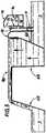
- the figure 2provides a schematic sectional and partial view of a case where the weld pool 9 gives rise to the formation of a double wave structure, a first so-called turbulent wave 8A relatively steep structure obtained through the nozzle structure 6A, and a second 8B wave laminar structure, providing a relatively large planar top surface, obtained it through the nozzle structure 6B.
- injection means 19 for the gas in the vicinity of one or other of the waves 8A, 8Bhave been shown in this figure.
- the figures 3 and 4illustrate the flow of the weld of the laminar wave 8B respectively in a situation of waiting for parts and brazing situation of a card 1, in the case of example of a machine provided with a plate or chute of spill.
- the figure 3illustrates a room waiting situation with flow of the weld upstream of the machine.
- the machine shown hereincludes the use of a weir system 10, in the form of a guide chute, located just downstream of the wave, and allowing by adjusting its height, to adjust the flow rate of discharge of the weld downstream here in this case a zero flow or almost zero.
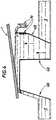
- the figure 5illustrates schematically and partially an embodiment of a soldering machine or tinning wave according to the invention, the representation being partial because centered on the arrangement laminar wave / injector / chute / skirt.
- the waveis here represented in the waiting position of parts with flow upstream.
- the figure 6is a schematic representation of a gas supply device according to the invention.
- the gas supply device 20 shown on the figure 6comprises a gas inlet pipe 22, a set of two secondary pipes 24 immersed in the solder bath 9 of the brazing or tinning machine (at a chosen location of the machine and suitable considering the geometry of the considered machine and therefore of the available space) and an injection pipe 26 supplying at least one gas injector, such as the injector 14 shown in FIG. figure 5 or one or more injectors 19/14 of the figure 2 .
- the two secondary lines 24have their inlet ends connected to the inlet pipe 22 and their outlet ends connected to the injection pipe 26.
- the inside diameter d of the secondary pipes and the flow rate of gas Q 0 in the inlet pipeare chosen such that the flow of the gas inside the secondary pipes is in a turbulent regime (and respecting the Reynolds relation mentioned above). ).
- the temperature of the gas at the outlet of the gas supply device according to the inventiondepends on parameters such as the flow regime of the gas in the pipe, the gas flow Q 0 in the inlet pipe. , the diameter of the secondary pipes or the submerged length of the secondary pipes.
- the gas flow rate Q 0 in the inlet pipe 22is advantageously greater than or equal to 1 Nm 3 .h -1 , preferably greater than or equal to 5 Nm 3 .h -1 and / or less than or equal to 15 Nm 3 .h -1 , preferably less than or equal to 10 Nm 3 .h -1 .
- the inventorshave observed, surprisingly, that heat exchange is optimized when the flow of gas in the secondary pipes is in a steady state. turbulent (whereas one might have thought on the contrary that it was better to adopt in the pipeline a very slow regime prolonging the heat exchange).
- the inner diameters of the secondary pipesare preferably less than or equal to 10 mm.
- the secondary lines immersed in the solder bathare preferably made of inert materials, for example stainless steel or titanium.
- the choice of materialsallows on the one hand a better heat exchange and on the other hand increased longevity of the secondary pipes, especially in the case of lead-free alloys which are corrosive.
- the inventorshave observed that by injecting nitrogen into a device as represented in FIG. figure 6 with an inside diameter d of the two secondary pipes of approximately 4 mm, a flow of gas Q 0 in the inlet pipe of approximately 5 m 3 ⁇ h -1 and a length of the secondary pipes of approximately 1.1 m , that the temperature of the nitrogen in the injection pipe is approximately 99% of the temperature of the weld pool.
- inputin other words for a given flow Q 0 , several couples (N, d) are possible so it is advantageous to choose the torque that has the largest range of flows respecting Reynolds and velocity relationships).
- the length L of the secondary linesis determined in such a way that The d ⁇ 100 and preferentially The d ⁇ 275.
Landscapes
- Engineering & Computer Science (AREA)
- Mechanical Engineering (AREA)
- Molten Solder (AREA)
- Electric Connection Of Electric Components To Printed Circuits (AREA)
- Arc Welding In General (AREA)
Description
Translated fromFrenchLa présente invention concerne un dispositif d'alimentation en gaz inerte d'une machine de brasage ou étamage à la vague.The present invention relates to an inert gas supply device of a soldering machine or tinning wave.
Ces machines de brasage ou d'étamage à la vague sont notamment utilisées pour le brasage de composants électroniques sur un support tel qu'un circuit électronique, ou encore pour l'étamage de terminaisons de composants électroniques. Le document
Au préalable, les pièces, ont généralement été fluxées dans une zone amont de la machine, de façon principalement à désoxyder les surfaces métalliques pour faciliter leur mouillage ultérieur par la soudure, l'opération de fluxage étant suivie d'une opération de préchauffage qui est pratiquée tant pour activer les flux précédemment déposés sur le circuit que pour préchauffer les circuits et les composants avant leur arrivée dans la zone chaude de brasage.Beforehand, the parts, have generally been fluxed in an upstream zone of the machine, mainly to deoxidize the metal surfaces to facilitate their subsequent wetting by welding, the fluxing operation being followed by a preheating operation which is practiced both to activate the flows previously deposited on the circuit and to preheat the circuits and components before their arrival in the hot brazing zone.
La configuration géométrique de la buse détermine la forme de vague de soudure obtenue. Les machines de brasage à la vague comportent le plus communément deux vagues, une première vague dite « turbulente » et une seconde vague dite « laminaire », ce second type de vague offrant une surface supérieure plane relativement étendue.The geometric configuration of the nozzle determines the weld wave shape obtained. The wave soldering machines most commonly comprise two waves, a first wave called "turbulent" and a second wave called "laminar", this second type of wave offering a relatively large flat top surface.
En l'absence de pièces à braser ou étamer dans la machine, la soudure liquide s'écoule, au niveau de cette vague laminaire, à très faible vitesse vers l'amont de la machine. Lors de l'arrivée d'une pièce au contact de la vague laminaire, on assiste à une inversion partielle de l'écoulement de l'alliage, une partie de cet alliage s'écoulant vers l'aval de la machine.In the absence of parts to be brazed or tinned in the machine, the liquid solder flows at this laminar wave at very low speed upstream of the machine. machine. Upon the arrival of a piece in contact with the laminar wave, there is a partial inversion of the flow of the alloy, a portion of this alloy flowing downstream of the machine.
Les machines sont alors souvent munies d'un système que l'on peut qualifier de déversoir, dont la hauteur permet de régler le débit d'écoulement de la soudure vers l'aval. Ce système de déversoir peut tout simplement être constitué d'une plaque métallique, ou encore d'une goulotte de guidage de la retombée de la soudure vers le bain environnant.The machines are often equipped with a system that can be described as spillway, the height of which adjusts the flow rate of the weld downstream. This spillway system can simply consist of a metal plate, or a chute for guiding the fallout of the weld to the surrounding bath.
Il est à noter que le débit et la direction de l'écoulement de l'alliage au niveau de cette vague laminaire ont une influence déterminante sur la qualité du brasage obtenu.It should be noted that the flow rate and the direction of flow of the alloy at this laminar wave have a decisive influence on the quality of the soldering obtained.
Il faut encore noter que certains utilisateurs, pour s'adapter aux caractéristiques très spécifiques de leur production, limitent considérablement le phénomène d'écoulement aval de la soudure, préférant mettre en place un débordement aval très faible voire quasiment nul de la soudure.It should also be noted that some users, in order to adapt to the very specific characteristics of their production, considerably limit the phenomenon of downstream flow of the weld, preferring to put in place a very weak or even almost zero downstream overflow of the weld.
Les machines de brasage ou d'étamage à la vague sont traditionnellement ouvertes à l'atmosphère d'air ambiant. Parmi les problèmes que rencontrent les utilisateurs de telles machines, on peut citer la formation de couches d'oxyde, appelées scories, à la surface du bain de soudure du fait de son exposition à l'air, entraînant une perte de soudure non négligeable et la nécessité de régulièrement nettoyer le bain. A titre indicatif, une machine de taille moyenne peut donner lieu à la formation de plus d'un kilogramme de scorie par heure de fonctionnement.Wave soldering or tinning machines are traditionally open to the ambient air atmosphere. Among the problems encountered by the users of such machines include the formation of oxide layers, called slag, on the surface of the weld pool because of its exposure to the air, resulting in a significant loss of welding and the need to regularly clean the bath. As an indication, a medium-sized machine can give rise to the formation of more than one kilogram of slag per hour of operation.
Si l'on considère maintenant le cas spécifique de la vague laminaire, on comprend aisément qu'un débordement aval nul ou trop faible de la soudure va présenter un inconvénient majeur, par le fait que les scories se formant en permanence sur la surface plane de la vague ne peuvent efficacement s'évacuer, et se déposent alors sur la pièce, entachant de façon significative la qualité de brasage ou étamage obtenue.If we now consider the specific case of the laminar wave, we can easily understand that an overflow downstream zero or too low of the weld will have a major disadvantage, in that the slag forming permanently on the flat surface of the wave can effectively evacuate, and then settle on the piece, significantly tainting the quality of soldering or tinning obtained.
Le phénomène de scories décrit ici dans le cas de la surface plane d'une vague laminaire d'une machine de brasage à la vague existe également dans le cas de la surface plane d'un bain mort (bain liquide stagnant).The slag phenomenon described here in the case of the flat surface of a laminar wave of a wave soldering machine also exists in the case of the flat surface of a dead bath (stagnant liquid bath).
Différentes solutions techniques ont jusqu'ici été proposées pour tenter de protéger le bain de soudure des phénomènes d'oxydation par l'air environnant. Ces solutions peuvent être classées en trois catégories :
- a) Une première catégorie de solution consiste dans la mise en place d'une atmosphère de protection confinée, au moins au dessus du bain de soudure, mais également parfois dans le reste de la machine. Il existe actuellement des machines entièrement inertées, conçues dès le départ comme un tunnel étanche. Le document
US-5 161 727 - b) Une seconde catégorie de solutions utilise la mise en place d'atmosphères de protection non confinées, via des injecteurs localisés à proximité des vagues de soudure, sans fermeture de l'espace situé au-dessus des vagues. On peut citer dans cette seconde catégorie les dispositifs rapportés dans le document
WO 93/11653 - c) La troisième catégorie de solutions au problème de la formation des scories met en oeuvre l'utilisation, à la surface de la vague laminaire, d'une pellicule d'huile à fort pouvoir couvrant.
- a) A first category of solution consists in the establishment of a confined protection atmosphere, at least above the welding bath, but also sometimes in the rest of the machine. There are currently fully inert machines, designed from the outset as a sealed tunnel. The document
US-5,161,727 - b) A second category of solutions uses the establishment of unconfined protection atmospheres, via injectors located near the welding waves, without closing the space above the waves. In this second category, mention may be made of the devices reported in the document
WO 93/11653 - c) The third category of solutions to the problem of slag formation involves the use of a film of oil with a high covering power on the surface of the laminar wave.
Les systèmes de protection à l'huile présentent les inconvénients classiques de l'utilisation d'huile (notamment en présence d'une source de température), qui sont en particulier la présence de dépôts d'huile sur la carte nécessitant la réalisation d'un nettoyage souvent difficile et imparfait, la nécessité de réaliser fréquemment des périodes de maintenance de la machine du fait de l'accumulation d'huile dans le bain de soudure, ou encore les émanations de vapeurs d'huile qui représentent incontestablement une nuisance pour l'environnement, qu'il soit matériel ou humain.Oil protection systems have the conventional disadvantages of the use of oil (especially in the presence of a temperature source), which are in particular the presence of oil deposits on the board requiring the production of oil. a cleaning often difficult and imperfect, the need for frequent periods of maintenance of the machine due to the accumulation of oil in the weld pool, or emanations of oil vapors that undoubtedly represent a nuisance to the environment. environment, whether material or human.
De nouvelles réglementations en matière d'environnement, dont la directive Européenne 2002/95/CE du 27 Janvier 2003 « relative à la limitation de l'utilisation de certaines substances dangereuses dans les équipements électriques et électroniques » interdisent, entre autre, l'utilisation de plomb dans les alliages de soudure.New environmental regulations, including the European Directive 2002/95 / EC of 27 January 2003 "on the restriction of the use of certain hazardous substances in electrical and electronic equipment" prohibit, inter alia, the use of lead in solder alloys.
Les alliages de soudure traditionnels à base de plomb ont des températures de fusion plus basses que les alliages de substitution. Par exemple, l'alliage traditionnel étain plomb Sn63-Pb37 a une température de fusion d'environ 183°C alors que l'alliage Sn Ag3 Cu0,5 (étain argent cuivre) a un point de fusion d'environ 217°C.Traditional lead-based solder alloys have lower melting temperatures than substitute alloys. For example, the traditional lead tin Sn63-Pb37 alloy has a melting temperature of about 183 ° C whereas the Sn Ag3 Cu0.5 alloy (copper silver tin) has a melting point of about 217 ° C.
L'utilisation de ces nouveaux alliages nécessite de modifier l'ensemble du procédé de brasage à la vague. Ces nouveaux alliages impliquent des contraintes et des problèmes nouveaux pour la mise en oeuvre de procédé de brasage à la vague, par exemple une température de préchauffage et de brasage plus élevées ou encore une oxydation accrue.The use of these new alloys requires modification of the entire wave soldering process. These new alloys involve new constraints and problems for the implementation of wave soldering process, for example a higher temperature of preheating and brazing or increased oxidation.
Le fait que les températures de préchauffage et de brasage soient supérieures pose un problème de maintient de la température du circuit lors de sa progression tout au long de la machine de brasage à la vague : notamment entre la fin du préchauffage et l'arrivée sur la première vague de brasage ainsi qu'entre les deux vagues de brasage. A ces deux points de passage du circuit, il se produit une chute de température préjudiciable à la qualité de brasage. Cette chute de température est accrue par l'injection du gaz inerte pour les machines équipées d'un système d'inertage localisé au bain de soudure. Un autre point préjudiciable au brasage concerne la sortie de la deuxième vague où la vitesse de refroidissement est accrue, entraînant un choc thermique important (pour les machines possédant une injection de gaz juste en aval de cette vague-ci).The fact that the preheating and brazing temperatures are higher poses a problem of maintaining the temperature of the circuit during its progression while at the same time. along the wave soldering machine: especially between the end of the preheating and the arrival on the first soldering wave and between the two brazing waves. At these two points of passage of the circuit, there is a drop in temperature detrimental to the quality of brazing. This temperature drop is increased by the injection of inert gas for machines equipped with a weld pool inerting system. Another prejudicial point to brazing concerns the exit of the second wave where the cooling rate is increased, resulting in a significant thermal shock (for machines with a gas injection just downstream of this wave).
Pour les machines ne possédant pas de système de chauffage du gaz avant injection, les utilisateurs sont contraints de compenser ces chutes de température en surchauffant les bains de soudures. Ces surchauffes sont préjudiciables au brasage et peuvent également endommager les composants électroniques.For machines that do not have a gas heating system before injection, users are forced to compensate for these temperature drops by overheating the solder baths. These overheats are detrimental to soldering and can also damage electronic components.
Un but de la présente invention est de proposer une solution permettant d'adapter les machines à braser à l'utilisation des nouveaux alliages à température de fusion plus élevées.An object of the present invention is to provide a solution for adapting the brazing machines to the use of new alloys at higher melting temperature.
L'invention propose ainsi un dispositif d'alimentation en gaz d'une machine de brasage ou étamage à la vague, machine apte à générer au moins une vague de soudure, comprenant :
- une canalisation d'entrée de gaz,
- un ensemble de N canalisations secondaires immergées dans le bain de soudure de la machine de brasage ou d'étamage et ,
- une canalisation d'injection alimentant au moins un moyen d'injection du gaz au voisinage de ladite au moins une vague,
se caractérisant en ce que le nombre N de canalisations secondaires est supérieur ou égal à 1 et en ce que le diamètre intérieur d des canalisations secondaires et le débit de gaz Q0 dans la canalisation d'entrée sont choisis tel que l'écoulement du gaz à l'intérieur des canalisations secondaires soit en régime turbulent.The invention thus proposes a device for supplying gas to a wave soldering or tinning machine, a machine capable of generating at least one wave of solder, comprising:
- a gas inlet pipe,
- a set of N secondary pipes immersed in the solder bath of the brazing or tinning machine and,
- an injection pipe feeding at least one gas injection means in the vicinity of said at least one wave,
characterized in that the number N of secondary lines is greater than or equal to 1 and in that the inner diameter d of the secondary lines and the flow rate of Q0 in the inlet line are chosen such that the flow of the gas inside the secondary pipes or turbulent regime.
Avantageusement et de façon surprenante, l'établissement d'un régime turbulent dans la ou les canalisations secondaires permet un meilleur échange thermique entre le gaz et le bain de soudure. La longueur et le nombre de canalisations secondaires s'en trouve avantageusement réduit.Advantageously and surprisingly, the establishment of a turbulent regime in the secondary pipe or lines allows a better heat exchange between the gas and the weld pool. The length and number of secondary pipes is advantageously reduced.
Un dispositif selon l'invention peut en outre comporter l'une ou plusieurs des caractéristiques optionnelles ci-dessous, considérées individuellement ou selon toutes les combinaisons possibles:
- le nombre N de canalisations secondaires, le débit de gaz Q0 dans la canalisation d'entrée en Nm3.s-1 (« normaux » m3 pour 0°C et 1013 mbars) et le diamètre intérieur d en mètres des canalisations secondaires vérifient la relation suivante (relation dite « de Reynolds » en sortie de canalisation secondaire) :

- le dispositif vérifie larelation « de longueur» suivante (« relation maximum de longueur ») :

- le dispositif vérifie larelation « de longueur» suivante (« relation minimum de longueur ») :

- les canalisations secondaires présentent un diamètre intérieur inférieur ou égal à 10 mm.
- le débit de gaz Q0 dans la canalisation d'entrée est inférieur ou égal à 15 Nm3.h-1, préférentiellement à 10 Nm3.h-1, et/ou supérieur ou égal à 1 Nm3.h-1.


- the number N of secondary pipes, the flow of gas Q0 in the inlet pipe in Nm3 .s-1 ("normal" m3 for 0 ° C and 1013 mbar) and the internal diameter d in meters of the secondary pipes verify the following relation ("Reynolds" relation at the exit of the secondary pipe):
- the device checks the following"length " relation ("maximum length relation"):
- the device checks the following"length " relationship ("minimum length relationship"):
- the secondary lines have an internal diameter less than or equal to 10 mm.
- the flow rate of gas Q0 in the inlet line is less than or equal to 15 Nm3 .h-1 , preferably 10 Nm3 .h-1 , and / or greater than or equal to 1 Nm3 .h-1 .
Comme il apparaîtra clairement à l'homme du métier, la longueur adoptée pour les canalisations immergée sera un des paramètres influençant la température du gaz en sortie des canalisations immergées et l'écart plus ou moins grand entre la température du bain et cette température de sortie.As will be clear to those skilled in the art, the length adopted for submerged pipelines will be one of the parameters influencing the temperature of the gas leaving the submerged pipelines and the greater or lesser difference between the bath temperature and this outlet temperature. .
Comme indiqué ci-dessus on adoptera avantageusement un ratio

L'invention se rapporte également à une machine de brasage ou d'étamage à la vague comprenant un dispositif d'alimentation en gaz selon l'invention.The invention also relates to a wave brazing or soldering machine comprising a gas supply device according to the invention.
On notera que l'on pourra déterminer une estimation du débit Q0 tout simplement par l'expérience (du fait de systèmes équivalents déjà réalisés, ou encore par expérimentations spécifiques pour la machine considérée) ceci selon l'objectif technique visé.It will be noted that it will be possible to determine an estimate of the flow rate Q0 simply by experience (because of equivalent systems already achieved, or else by specific experiments for the machine in question) according to the technical objective in question.
Par exemple afin d'atteindre une teneur résiduelle en oxygène au niveau du bain en deçà d'une teneur limite (on peut déterminer ce débit en dehors de la présence du système de réchauffage selon l'invention, en gardant à l'esprit le fait que l'action de chauffer le gaz dans les
canalisations immergées va générer une expansion volumique, et l'on pourra donc estimer un débit plus faible qui tient compte de la température en sortie du système.For example in order to reach a residual oxygen content in the bath below a limit content (this flow can be determined outside the presence of the heating system according to the invention, bearing in mind the fact that that the action of heating the gas in the
submerged pipelines will generate a volume expansion, and we can therefore estimate a lower flow rate that takes into account the temperature at the output of the system.
En d'autres termes la détermination du débit se fera selon l'objectif recherché : si l'objectif de l'utilisateur est avant tout de minimiser la consommation de gaz alors on s'efforcera de tenir compte de l'expansion volumique ; si l'objectif est avant tout thermique (maintient de la température de la carte entre les vagues, réduire la pente de refroidissement etc ...) alors on pourra ne pas tenir compte du phénomène d'expansion volumique.In other words, the determination of the flow will be made according to the desired objective: if the objective of the user is first of all to minimize the consumption of gas then one will try to take account of the volume expansion; if the objective is above all thermal (maintains the temperature of the map between the waves, reduce the cooling slope etc ...) then we can ignore the phenomenon of volume expansion.
L'invention concerne également un procédé de brasage ou d'étamage à la vague, au cours duquel une pièce à braser ou étamer est amenée en contact avec au moins une vague de soudure liquide, selon lequel on dirige un gaz sur au moins une portion de ladite au moins une vague, au moyen d'un moyen d'injection de gaz, et où le moyen d'injection de gaz est alimenté en gaz par un dispositif d'alimentation selon l'invention.The invention also relates to a wave soldering or tinning process, in which a workpiece to be brazed or tinned is brought into contact with at least one wave of liquid solder, wherein a gas is directed on at least one portion said at least one wave, by means of a gas injection means, and wherein the gas injection means is supplied with gas by a supply device according to the invention.
L'invention sera mieux comprise à la lecture de la description qui va suivre, donnée uniquement à titre d'exemple et faite en se référant aux dessins annexés dans lesquels:
- la
figure 1 est une représentation schématique d'une structure classique de machine de brasage à la vague ; - la
figure 2 est une coupe partielle et schématique d'une structure à deux vagues, turbulente et laminaire, faisant figurer certaines positions du moyen d'injection de gaz parmi les nombreuses possibilités envisageables ; - la
figure 3 est une représentation schématique d'une vague laminaire en situation d'attente de pièces (écoulement de soudure vers l'amont) ; - la
figure 4 est une représentation schématique d'une vague laminaire en situation de brasage (avec écoulement de la soudure partiellement inversé : une partie de la soudure s'écoule vers l'aval avec déversement dans la goulotte 10); - la
figure 5 est une représentation schématique partielle d'une machine conforme à l'invention; - la
figure 6 est une vue schématique d'un dispositif d'alimentation en gaz selon l'invention.
- the
figure 1 is a schematic representation of a conventional wave soldering machine structure; - the
figure 2 is a partial and schematic sectional view of a turbulent and laminar two-wave structure, showing certain positions of the gas injection means among the many possibilities that can be envisaged; - the
figure 3 is a schematic representation of a laminar wave waiting for parts (weld flow upstream); - the
figure 4 is a schematic representation of a laminar wave in brazing situation (with flow of the partially inverted weld: part of the weld flows downstream with discharge in the trough 10); - the
figure 5 is a partial schematic representation of a machine according to the invention; - the
figure 6 is a schematic view of a gas supply device according to the invention.
Pour des raisons de clarté, les différents éléments représentés sur les figures ne sont pas nécessairement à l'échelle.For the sake of clarity, the different elements shown in the figures are not necessarily to scale.
Au sens de l'invention, on entend par « gaz » tout type de gaz, qu'il soit neutre, comme l'azote, quel que soit son mode de production et sa pureté, ou bien actif comme par exemple des mélanges gaz neutre/gaz réducteur.For the purposes of the invention, the term "gas" means any type of gas, be it neutral, such as nitrogen, regardless of its production method and purity, or active, such as for example neutral gas mixtures. / reducing gas.
La machine de brasage à la vague schématisée en
Les cartes 1 sont convoyées le long des différentes zones de la machine à l'aide d'un système de convoyage 2, constitué par exemple de chaînes de convoyage « à doigts ».The cards 1 are conveyed along the different areas of the machine using a conveying
La
On a fait figurer sur cette figure, plusieurs exemples de moyens d'injection 19 du gaz au voisinage de l'une ou l'autre des vagues 8A, 8B.The
Several examples of injection means 19 for the gas in the vicinity of one or other of the
Les
La
La
La
La vague est ici représentée en position d'attente de pièces avec écoulement vers l'amont.The wave is here represented in the waiting position of parts with flow upstream.
On reconnaît alors sur la figure la présence d'une jupe plongeante 11, solidaire du système de goulotte 10, en regard desquels est positionné un injecteur de gaz 12, possédant une face ou paroi 17, qui comporte deux groupes d'orifices 15 et 16.It is then possible to recognize in the figure the presence of a plunging skirt 11, integral with the
Comme on l'aura compris, on a fait le choix de représenter sur cette
Les groupes d'orifices 15 et 16 sont respectivement positionnés de façon à pouvoir diriger un premier jet de gaz vers la surface plane de la vague laminaire 8b, et un second jet de gaz à l'intérieur de la jupe plongeante 11. La présence de la jupe plongeante et du second jet de gaz à l'intérieur de la jupe est tout particulièrement efficace pour éviter d'éventuels effets d'entraînement d'air sur la surface plane de la vague laminaire.The groups of
On remarquera la présence à l'intérieur de l'injecteur 19 d'un tube poreux 14, alimenté depuis une canalisation d'injection d'un dispositif alimentation en gaz selon l'invention, et répartissant ce gaz à l'intérieur de la chambre d'expansion que constitue le corps de l'injecteur 19.Note the presence inside the
La
Le dispositif 20 d'alimentation de gaz représenté sur la
Les deux canalisations secondaires 24 ont leurs extrémités d'entrée liées à la canalisation d'entrée 22 et leurs extrémités de sortie liées à la canalisation d'injection 26.The two
Le diamètre intérieur d des canalisations secondaires et le débit de gaz Q0 dans la canalisation d'entrée sont choisis tel que l'écoulement du gaz à l'intérieur des canalisations secondaires soit en régime turbulent (et respectant la relation de Reynolds évoquée plus haut).The inside diameter d of the secondary pipes and the flow rate of gas Q0 in the inlet pipe are chosen such that the flow of the gas inside the secondary pipes is in a turbulent regime (and respecting the Reynolds relation mentioned above). ).
Les inventeurs ont observé que la température du gaz en sortie du dispositif d'alimentation en gaz selon l'invention dépend de paramètres tels que le régime d'écoulement du gaz dans la canalisation, le débit de gaz Q0 dans la canalisation d'entrée, le diamètre des canalisations secondaires ou encore la longueur immergée des canalisations secondaires.The inventors have observed that the temperature of the gas at the outlet of the gas supply device according to the invention depends on parameters such as the flow regime of the gas in the pipe, the gas flow Q0 in the inlet pipe. , the diameter of the secondary pipes or the submerged length of the secondary pipes.
En pratique, le débit de gaz Q0 dans la canalisation d'entrée 22 est avantageusement supérieur ou égal à 1 Nm3.h-1, de préférence supérieur ou égal à 5 Nm3.h-1 et/ou inférieur ou égal à 15 Nm3.h-1, de préférence inférieur ou égal à 10 Nm3.h-1.In practice, the gas flow rate Q0 in the
Les inventeurs ont observé de manière surprenante que les échanges thermiques sont optimisés lorsque l'écoulement du gaz dans les canalisations secondaires se fait en régime turbulent (alors que l'on aurait pu penser au contraire qu'il était préférable d'adopter dans la canalisation un régime très lent prolongeant l'échange thermique).The inventors have observed, surprisingly, that heat exchange is optimized when the flow of gas in the secondary pipes is in a steady state. turbulent (whereas one might have thought on the contrary that it was better to adopt in the pipeline a very slow regime prolonging the heat exchange).
Afin d'éviter les nuisances sonores et les pertes de charges trop importantes, la relation de vitesse précédemment énoncée est préférentiellement respectée.In order to avoid noise pollution and excessive head losses, the speed relationship previously stated is preferably respected.
Dans la pratique, étant donné les débits de gaz dans la canalisation d'entrée de gaz et la géométrie des machines de brasage à la vague, les diamètres intérieurs des canalisations secondaires sont préférentiellement inférieurs ou égaux à 10 mm.In practice, given the gas flow rates in the gas inlet pipe and the geometry of wave soldering machines, the inner diameters of the secondary pipes are preferably less than or equal to 10 mm.
Les canalisations secondaires immergées dans le bain de soudure sont de préférence constituées de matériaux inertes, par exemple en acier inoxydable ou en titane.The secondary lines immersed in the solder bath are preferably made of inert materials, for example stainless steel or titanium.
Avantageusement, le choix des matériaux permet d'un part un meilleur échange thermique et d'autre part une longévité accrue des canalisations secondaires, notamment dans le cas des alliages sans plomb qui sont corrosifs.Advantageously, the choice of materials allows on the one hand a better heat exchange and on the other hand increased longevity of the secondary pipes, especially in the case of lead-free alloys which are corrosive.
Les inventeurs ont observé qu'en injectant de l'azote dans un dispositif tel que représenté à la
Avantageusement, plus l'intervalle de valeurs possibles pour les valeurs de débit Q0 de gaz dans la canalisation d'entrée est grand, plus les performances de la machine de brasage à la vague sont indépendants de la stabilité du débit de gaz dans la canalisation d'entrée (en d'autres termes pour un débit donné Q0, plusieurs couples (N,d) sont possibles il est donc avantageux de choisir le couple qui présente la plus grand plage de débits respectant les relations de Reynolds et de vitesse).Advantageously, the larger the range of possible values for the flow rate values Q0 of gas in the inlet pipe, the greater the performance of the wave soldering machine is independent of the stability of the flow of gas in the pipe. input (in other words for a given flow Q0 , several couples (N, d) are possible so it is advantageous to choose the torque that has the largest range of flows respecting Reynolds and velocity relationships).
Pour chaque couple (N, d) la longueur L des canalisations secondaire est déterminée de manière à ce que

Claims (8)
- Device for feeding (20) gas to a wave brazing or tinning machine, said machine able to generate at least one soldering wave, comprising:- a gas inlet channel (22),- a set of N secondary channels (24) immersed in the solder bath (9) of the brazing or tinning machine and,- an injection channel (26) supplying at least one injection means (14, 19) for injecting the gas in the vicinity of said at least one wave (8A, 8B),- with each secondary channel (24) having its inlet end connected to the inlet channel (22) and its outlet end connected to the injection channel (26),characterised in that the number N of secondary channels (24) is greater than or equal to 1 andin that the inner diameter d of the secondary channels (24) and the gas flow rate Q0 in the inlet channel (22) are chosen such that the gas flow inside the secondary channels (24) is in a turbulent mode.
- Device according to claim 1,characterised in that the number N of secondary channels (24), the gas flow rate Q0 in the inlet channel (22) in Nm3.s-1 and the inner diameter d in metres of the secondary channels satisfy the following relationship ("Reynolds" relationship at the outlet of the secondary channel):

with ρ0 the density of the gas in kg.m-3 (in "normal" conditions at 0°C and 1013 mbars) and µs the dynamic viscosity of the gas in Pa.s. at the outlet of each secondary channel. - Device as claimed in any preceding claimcharacterised in that

- Device as claimed in any preceding claimcharacterised in that

- Device as claimed in any preceding claimcharacterised in that the secondary channels (24) have an inner diameter d less than or equal to 10 mm.
- Device as claimed in any preceding claimcharacterised in that the gas flow rate Q0 in the inlet channel (22) is less than or equal to 15 Nm3.h-1, and/ or greater than or equal to 1 Nm3.h-1.
- Wave brazing or tinning machine comprising a device as claimed in any preceding claim.
- Method for wave brazing or tinning, during which a part to be brazed or tinned (1) is brought into contact with at least one liquid soldering wave (8A, 8B), according to which a gas is directed onto at least one portion of the wave by means of a gas injection means (19, 14),characterised in that the gas injection means is supplied with gas by a supply device (20) according to any of claims 1 to 6.


Priority Applications (1)
| Application Number | Priority Date | Filing Date | Title |
|---|---|---|---|
| PL09703454TPL2240291T3 (en) | 2008-01-10 | 2009-01-08 | Device for feeding gas to a wave brazing or tinning machine |
Applications Claiming Priority (2)
| Application Number | Priority Date | Filing Date | Title |
|---|---|---|---|
| FR0850122AFR2926233B1 (en) | 2008-01-10 | 2008-01-10 | DEVICE FOR SUPPLYING GAS TO A SOLDERING MACHINE OR WINDING PLASTER. |
| PCT/FR2009/050019WO2009092937A2 (en) | 2008-01-10 | 2009-01-08 | Device for feeding gas to a wave brazing or tinning machine |
Publications (2)
| Publication Number | Publication Date |
|---|---|
| EP2240291A2 EP2240291A2 (en) | 2010-10-20 |
| EP2240291B1true EP2240291B1 (en) | 2017-09-06 |
Family
ID=39764746
Family Applications (1)
| Application Number | Title | Priority Date | Filing Date |
|---|---|---|---|
| EP09703454.0AActiveEP2240291B1 (en) | 2008-01-10 | 2009-01-08 | Device for feeding gas to a wave brazing or tinning machine |
Country Status (8)
| Country | Link |
|---|---|
| US (2) | US20100276475A1 (en) |
| EP (1) | EP2240291B1 (en) |
| JP (1) | JP2011510816A (en) |
| CN (1) | CN101909800B (en) |
| ES (1) | ES2643668T3 (en) |
| FR (1) | FR2926233B1 (en) |
| PL (1) | PL2240291T3 (en) |
| WO (1) | WO2009092937A2 (en) |
Families Citing this family (8)
| Publication number | Priority date | Publication date | Assignee | Title |
|---|---|---|---|---|
| DE202009011875U1 (en)* | 2009-09-02 | 2009-12-03 | Air Liquide Deutschland Gmbh | Apparatus for supplying an inert gas to a wave soldering machine |
| US20140027495A1 (en)* | 2012-04-18 | 2014-01-30 | Air Products And Chemicals Inc. | Apparatus And Method For Providing An Inerting Gas During Soldering |
| CN105324203B (en)* | 2013-06-13 | 2018-04-17 | 富士通天株式会社 | Brazing device and method for welding |
| CN104801809B (en)* | 2014-01-29 | 2018-09-14 | 气体产品与化学公司 | Device and method for providing inert gas during welding |
| JP6849909B2 (en)* | 2017-02-07 | 2021-03-31 | 富士通株式会社 | Soldering method, soldering equipment, and method of keeping the solder wet of the jet nozzle |
| US20190366460A1 (en)* | 2018-06-01 | 2019-12-05 | Progress Y&Y Corp. | Soldering apparatus and solder nozzle module thereof |
| CN110202232B (en)* | 2019-04-26 | 2024-02-13 | 广东盛控达智能科技有限公司 | Automatic soldering tin machine of selectivity wave soldering |
| JP7141001B1 (en)* | 2021-05-14 | 2022-09-22 | 千住金属工業株式会社 | jet soldering machine |
Family Cites Families (20)
| Publication number | Priority date | Publication date | Assignee | Title |
|---|---|---|---|---|
| JPS6115094A (en)* | 1984-06-29 | 1986-01-23 | Mitsubishi Metal Corp | Heat transfer tube for use in heat exchanger |
| US4676305A (en)* | 1985-02-11 | 1987-06-30 | Doty F David | Microtube-strip heat exchanger |
| JPS62112996A (en)* | 1985-11-11 | 1987-05-23 | Mitsubishi Metal Corp | Heat-transmitting body |
| JPS62206383A (en)* | 1986-03-05 | 1987-09-10 | Mitsubishi Metal Corp | Heat transfer body |
| FR2670986B1 (en)* | 1990-12-20 | 1996-08-02 | Air Liquide | WELDING BATH INERTAGE DEVICE OF A WAVE WELDING MACHINE. |
| JPH0621639A (en)* | 1992-06-30 | 1994-01-28 | Aiwa Co Ltd | Soldering equipment |
| JPH0798324A (en)* | 1992-10-27 | 1995-04-11 | Semiconductor Energy Lab Co Ltd | Measuring device and operating method thereof |
| JPH0665784U (en)* | 1993-02-24 | 1994-09-16 | 株式会社河村バーナー製作所 | Heat exchanger |
| FR2713952B1 (en)* | 1993-12-22 | 1996-01-12 | Air Liquide | Device and method for injecting gas for the formation of a controlled atmosphere in a confined space. |
| US5520320A (en)* | 1994-04-22 | 1996-05-28 | Air Liquide America Corporation | Process for wave soldering components on a printed circuit board in a temperature controlled non-oxidizing atmosphere |
| US5806585A (en)* | 1995-02-27 | 1998-09-15 | Mitsubishi Denki Kabushiki Kaisha | Heat exchanger, refrigeration system, air conditioner, and method and apparatus for fabricating heat exchanger |
| JP3311547B2 (en)* | 1995-08-02 | 2002-08-05 | 日本電熱計器株式会社 | Soldering equipment |
| FR2748410B1 (en)* | 1996-05-07 | 1998-06-05 | Air Liquide | METHOD AND MACHINE FOR BRAZING OR TINNING ON THE WAVE |
| US6305596B1 (en)* | 1998-06-18 | 2001-10-23 | Asustek Computer Inc. | Apparatus and method for soldering through-hole components on circuit board |
| US7140425B2 (en)* | 2001-05-01 | 2006-11-28 | Julian Romero-Beltran | Plate-tube type heat exchanger |
| JP2004340485A (en)* | 2003-05-15 | 2004-12-02 | Calsonic Kansei Corp | Complex heat exchanger |
| JP2004106061A (en)* | 2003-12-17 | 2004-04-08 | Matsushita Electric Ind Co Ltd | Manufacturing method of printed circuit board unit and soldering device |
| KR101297611B1 (en)* | 2004-04-16 | 2013-08-19 | 피. 케이 메탈 인코포레이티드 | Soldering process |
| US20050274489A1 (en)* | 2004-06-10 | 2005-12-15 | Brand Joseph H | Heat exchange device and method |
| US7760502B2 (en)* | 2007-10-23 | 2010-07-20 | International Business Machines Corporation | Cooling system employing a heat exchanger with phase change material, and method of operation thereof |
- 2008
- 2008-01-10FRFR0850122Apatent/FR2926233B1/ennot_activeExpired - Fee Related
- 2009
- 2009-01-08JPJP2010541827Apatent/JP2011510816A/enactivePending
- 2009-01-08WOPCT/FR2009/050019patent/WO2009092937A2/enactiveApplication Filing
- 2009-01-08ESES09703454.0Tpatent/ES2643668T3/enactiveActive
- 2009-01-08EPEP09703454.0Apatent/EP2240291B1/enactiveActive
- 2009-01-08CNCN200980101963.8Apatent/CN101909800B/enactiveActive
- 2009-01-08USUS12/812,284patent/US20100276475A1/ennot_activeAbandoned
- 2009-01-08PLPL09703454Tpatent/PL2240291T3/enunknown
- 2012
- 2012-01-27USUS13/359,888patent/US20120125982A1/ennot_activeAbandoned
Non-Patent Citations (1)
| Title |
|---|
| None* |
Also Published As
| Publication number | Publication date |
|---|---|
| CN101909800B (en) | 2016-06-29 |
| FR2926233B1 (en) | 2010-08-13 |
| WO2009092937A2 (en) | 2009-07-30 |
| JP2011510816A (en) | 2011-04-07 |
| EP2240291A2 (en) | 2010-10-20 |
| ES2643668T3 (en) | 2017-11-23 |
| FR2926233A1 (en) | 2009-07-17 |
| US20120125982A1 (en) | 2012-05-24 |
| CN101909800A (en) | 2010-12-08 |
| US20100276475A1 (en) | 2010-11-04 |
| WO2009092937A3 (en) | 2009-11-05 |
| PL2240291T3 (en) | 2018-01-31 |
Similar Documents
| Publication | Publication Date | Title |
|---|---|---|
| EP2240291B1 (en) | Device for feeding gas to a wave brazing or tinning machine | |
| EP0806262B1 (en) | Method and apparatus for wave soldering or wave tinplating | |
| EP1927426B1 (en) | Process of laser drilling a ceramic matrix composite material workpiece | |
| EP4039403A1 (en) | Method of manufacturing a welded sheet-metal blank, welded sheet-metal blank, device for manufacturing welded flanges, and workpiece manufactured from such welded sheet-metal blank | |
| EP0592309A1 (en) | Process for nitriding a titanium alloy workpiece and device for spraying nitrogen and inert gas | |
| CH652331A5 (en) | WELDING PLIERS. | |
| FR2908061A1 (en) | DEVICE AND METHOD FOR AUTOMATIC WELDING IN WATER FOR THE PRODUCTION ON A SURFACE OF A WELDING SEAL. | |
| LU86568A1 (en) | METHOD AND DEVICE FOR FORMING A REFRACTORY MASS ON A SURFACE | |
| LU86606A1 (en) | CORE TUBULAR METALLIC ELECTRODE AND USE OF THIS ELECTRODE FOR ARC CUTTING OF METALS | |
| CA2517949A1 (en) | Laser/mig hybrid welding process with high wire speed | |
| EP0304654B1 (en) | Process for welding a groove machined in a massive steel work piece, and use of this process to repair a fissured rotor | |
| EP0659515A1 (en) | Gas injection device and process for forming a controlled atmosphere in a confined space | |
| FR2678535A1 (en) | APPARATUS FOR AUTOMATIC WELDING. | |
| EP2939782B1 (en) | Plasma arc-cutting method and facility with improved drilling cycle | |
| WO2017009264A1 (en) | Method allowing the removal of oxides present on the surface of nodules of a metal powder before using same in an industrial method | |
| EP0599737B1 (en) | Build-up procedure on a work piece by plasma with transferred arc | |
| EP0686844A1 (en) | Method and device for measuring wettability in a controlled atmosphere | |
| EP0743114B2 (en) | Process for the lubrication of the walls of a continuous casting mould for metals and mould for carrying out the process | |
| EP0033270B1 (en) | Method of cutting a metal or a metal-alloy wall by splitting | |
| EP0028569B1 (en) | Process for agitating a molten metal by injection of gases | |
| JP6790972B2 (en) | Hot metal plating equipment and hot metal plating method | |
| WO2010139882A2 (en) | Method and equipment for treating the alloy of the entirety or a portion of the dead area of a soldering bath of a wave brazing or tinning machine for entirely or partially removing the oxide slag formed in the machine bath | |
| EP1900469B1 (en) | Remote laser welding with sending of liquid argon as a protective atmosphere | |
| FR2746046A1 (en) | TIG WELDING PROCESS WITH CORDED CORD AND CORDED CORDED CORD | |
| BE839729A (en) | VERTICAL WELDING PROCESS |
Legal Events
| Date | Code | Title | Description |
|---|---|---|---|
| PUAI | Public reference made under article 153(3) epc to a published international application that has entered the european phase | Free format text:ORIGINAL CODE: 0009012 | |
| 17P | Request for examination filed | Effective date:20100810 | |
| AK | Designated contracting states | Kind code of ref document:A2 Designated state(s):AT BE BG CH CY CZ DE DK EE ES FI FR GB GR HR HU IE IS IT LI LT LU LV MC MK MT NL NO PL PT RO SE SI SK TR | |
| AX | Request for extension of the european patent | Extension state:AL BA RS | |
| DAX | Request for extension of the european patent (deleted) | ||
| STAA | Information on the status of an ep patent application or granted ep patent | Free format text:STATUS: EXAMINATION IS IN PROGRESS | |
| 17Q | First examination report despatched | Effective date:20170217 | |
| GRAP | Despatch of communication of intention to grant a patent | Free format text:ORIGINAL CODE: EPIDOSNIGR1 | |
| STAA | Information on the status of an ep patent application or granted ep patent | Free format text:STATUS: GRANT OF PATENT IS INTENDED | |
| INTG | Intention to grant announced | Effective date:20170519 | |
| GRAS | Grant fee paid | Free format text:ORIGINAL CODE: EPIDOSNIGR3 | |
| GRAA | (expected) grant | Free format text:ORIGINAL CODE: 0009210 | |
| STAA | Information on the status of an ep patent application or granted ep patent | Free format text:STATUS: THE PATENT HAS BEEN GRANTED | |
| AK | Designated contracting states | Kind code of ref document:B1 Designated state(s):AT BE BG CH CY CZ DE DK EE ES FI FR GB GR HR HU IE IS IT LI LT LU LV MC MK MT NL NO PL PT RO SE SI SK TR | |
| REG | Reference to a national code | Ref country code:GB Ref legal event code:FG4D Free format text:NOT ENGLISH | |
| REG | Reference to a national code | Ref country code:CH Ref legal event code:EP Ref country code:AT Ref legal event code:REF Ref document number:925330 Country of ref document:AT Kind code of ref document:T Effective date:20170915 | |
| REG | Reference to a national code | Ref country code:IE Ref legal event code:FG4D Free format text:LANGUAGE OF EP DOCUMENT: FRENCH | |
| REG | Reference to a national code | Ref country code:DE Ref legal event code:R096 Ref document number:602009048154 Country of ref document:DE | |
| REG | Reference to a national code | Ref country code:SE Ref legal event code:TRGR | |
| REG | Reference to a national code | Ref country code:ES Ref legal event code:FG2A Ref document number:2643668 Country of ref document:ES Kind code of ref document:T3 Effective date:20171123 | |
| REG | Reference to a national code | Ref country code:NL Ref legal event code:MP Effective date:20170906 | |
| REG | Reference to a national code | Ref country code:FR Ref legal event code:PLFP Year of fee payment:10 | |
| REG | Reference to a national code | Ref country code:LT Ref legal event code:MG4D | |
| PG25 | Lapsed in a contracting state [announced via postgrant information from national office to epo] | Ref country code:NO Free format text:LAPSE BECAUSE OF FAILURE TO SUBMIT A TRANSLATION OF THE DESCRIPTION OR TO PAY THE FEE WITHIN THE PRESCRIBED TIME-LIMIT Effective date:20171206 Ref country code:LT Free format text:LAPSE BECAUSE OF FAILURE TO SUBMIT A TRANSLATION OF THE DESCRIPTION OR TO PAY THE FEE WITHIN THE PRESCRIBED TIME-LIMIT Effective date:20170906 Ref country code:HR Free format text:LAPSE BECAUSE OF FAILURE TO SUBMIT A TRANSLATION OF THE DESCRIPTION OR TO PAY THE FEE WITHIN THE PRESCRIBED TIME-LIMIT Effective date:20170906 Ref country code:FI Free format text:LAPSE BECAUSE OF FAILURE TO SUBMIT A TRANSLATION OF THE DESCRIPTION OR TO PAY THE FEE WITHIN THE PRESCRIBED TIME-LIMIT Effective date:20170906 | |
| REG | Reference to a national code | Ref country code:AT Ref legal event code:MK05 Ref document number:925330 Country of ref document:AT Kind code of ref document:T Effective date:20170906 | |
| PG25 | Lapsed in a contracting state [announced via postgrant information from national office to epo] | Ref country code:LV Free format text:LAPSE BECAUSE OF FAILURE TO SUBMIT A TRANSLATION OF THE DESCRIPTION OR TO PAY THE FEE WITHIN THE PRESCRIBED TIME-LIMIT Effective date:20170906 Ref country code:GR Free format text:LAPSE BECAUSE OF FAILURE TO SUBMIT A TRANSLATION OF THE DESCRIPTION OR TO PAY THE FEE WITHIN THE PRESCRIBED TIME-LIMIT Effective date:20171207 Ref country code:BG Free format text:LAPSE BECAUSE OF FAILURE TO SUBMIT A TRANSLATION OF THE DESCRIPTION OR TO PAY THE FEE WITHIN THE PRESCRIBED TIME-LIMIT Effective date:20171206 | |
| PGFP | Annual fee paid to national office [announced via postgrant information from national office to epo] | Ref country code:PL Payment date:20171220 Year of fee payment:10 | |
| PG25 | Lapsed in a contracting state [announced via postgrant information from national office to epo] | Ref country code:NL Free format text:LAPSE BECAUSE OF FAILURE TO SUBMIT A TRANSLATION OF THE DESCRIPTION OR TO PAY THE FEE WITHIN THE PRESCRIBED TIME-LIMIT Effective date:20170906 | |
| PG25 | Lapsed in a contracting state [announced via postgrant information from national office to epo] | Ref country code:RO Free format text:LAPSE BECAUSE OF FAILURE TO SUBMIT A TRANSLATION OF THE DESCRIPTION OR TO PAY THE FEE WITHIN THE PRESCRIBED TIME-LIMIT Effective date:20170906 Ref country code:CZ Free format text:LAPSE BECAUSE OF FAILURE TO SUBMIT A TRANSLATION OF THE DESCRIPTION OR TO PAY THE FEE WITHIN THE PRESCRIBED TIME-LIMIT Effective date:20170906 | |
| PG25 | Lapsed in a contracting state [announced via postgrant information from national office to epo] | Ref country code:EE Free format text:LAPSE BECAUSE OF FAILURE TO SUBMIT A TRANSLATION OF THE DESCRIPTION OR TO PAY THE FEE WITHIN THE PRESCRIBED TIME-LIMIT Effective date:20170906 Ref country code:IS Free format text:LAPSE BECAUSE OF FAILURE TO SUBMIT A TRANSLATION OF THE DESCRIPTION OR TO PAY THE FEE WITHIN THE PRESCRIBED TIME-LIMIT Effective date:20180106 Ref country code:SK Free format text:LAPSE BECAUSE OF FAILURE TO SUBMIT A TRANSLATION OF THE DESCRIPTION OR TO PAY THE FEE WITHIN THE PRESCRIBED TIME-LIMIT Effective date:20170906 Ref country code:AT Free format text:LAPSE BECAUSE OF FAILURE TO SUBMIT A TRANSLATION OF THE DESCRIPTION OR TO PAY THE FEE WITHIN THE PRESCRIBED TIME-LIMIT Effective date:20170906 | |
| PGFP | Annual fee paid to national office [announced via postgrant information from national office to epo] | Ref country code:SE Payment date:20180119 Year of fee payment:10 Ref country code:IT Payment date:20180129 Year of fee payment:10 Ref country code:TR Payment date:20180102 Year of fee payment:10 | |
| REG | Reference to a national code | Ref country code:DE Ref legal event code:R097 Ref document number:602009048154 Country of ref document:DE | |
| PLBE | No opposition filed within time limit | Free format text:ORIGINAL CODE: 0009261 | |
| STAA | Information on the status of an ep patent application or granted ep patent | Free format text:STATUS: NO OPPOSITION FILED WITHIN TIME LIMIT | |
| PG25 | Lapsed in a contracting state [announced via postgrant information from national office to epo] | Ref country code:DK Free format text:LAPSE BECAUSE OF FAILURE TO SUBMIT A TRANSLATION OF THE DESCRIPTION OR TO PAY THE FEE WITHIN THE PRESCRIBED TIME-LIMIT Effective date:20170906 | |
| 26N | No opposition filed | Effective date:20180607 | |
| PG25 | Lapsed in a contracting state [announced via postgrant information from national office to epo] | Ref country code:SI Free format text:LAPSE BECAUSE OF FAILURE TO SUBMIT A TRANSLATION OF THE DESCRIPTION OR TO PAY THE FEE WITHIN THE PRESCRIBED TIME-LIMIT Effective date:20170906 | |
| REG | Reference to a national code | Ref country code:CH Ref legal event code:PL | |
| PG25 | Lapsed in a contracting state [announced via postgrant information from national office to epo] | Ref country code:MT Free format text:LAPSE BECAUSE OF FAILURE TO SUBMIT A TRANSLATION OF THE DESCRIPTION OR TO PAY THE FEE WITHIN THE PRESCRIBED TIME-LIMIT Effective date:20170906 | |
| PG25 | Lapsed in a contracting state [announced via postgrant information from national office to epo] | Ref country code:LU Free format text:LAPSE BECAUSE OF NON-PAYMENT OF DUE FEES Effective date:20180108 | |
| REG | Reference to a national code | Ref country code:IE Ref legal event code:MM4A | |
| REG | Reference to a national code | Ref country code:BE Ref legal event code:MM Effective date:20180131 | |
| PG25 | Lapsed in a contracting state [announced via postgrant information from national office to epo] | Ref country code:LI Free format text:LAPSE BECAUSE OF NON-PAYMENT OF DUE FEES Effective date:20180131 Ref country code:BE Free format text:LAPSE BECAUSE OF NON-PAYMENT OF DUE FEES Effective date:20180131 Ref country code:CH Free format text:LAPSE BECAUSE OF NON-PAYMENT OF DUE FEES Effective date:20180131 | |
| PG25 | Lapsed in a contracting state [announced via postgrant information from national office to epo] | Ref country code:IE Free format text:LAPSE BECAUSE OF NON-PAYMENT OF DUE FEES Effective date:20180108 | |
| PG25 | Lapsed in a contracting state [announced via postgrant information from national office to epo] | Ref country code:MC Free format text:LAPSE BECAUSE OF FAILURE TO SUBMIT A TRANSLATION OF THE DESCRIPTION OR TO PAY THE FEE WITHIN THE PRESCRIBED TIME-LIMIT Effective date:20170906 | |
| PG25 | Lapsed in a contracting state [announced via postgrant information from national office to epo] | Ref country code:SE Free format text:LAPSE BECAUSE OF NON-PAYMENT OF DUE FEES Effective date:20190109 | |
| PG25 | Lapsed in a contracting state [announced via postgrant information from national office to epo] | Ref country code:IT Free format text:LAPSE BECAUSE OF NON-PAYMENT OF DUE FEES Effective date:20190108 | |
| PG25 | Lapsed in a contracting state [announced via postgrant information from national office to epo] | Ref country code:HU Free format text:LAPSE BECAUSE OF FAILURE TO SUBMIT A TRANSLATION OF THE DESCRIPTION OR TO PAY THE FEE WITHIN THE PRESCRIBED TIME-LIMIT; INVALID AB INITIO Effective date:20090108 Ref country code:PT Free format text:LAPSE BECAUSE OF FAILURE TO SUBMIT A TRANSLATION OF THE DESCRIPTION OR TO PAY THE FEE WITHIN THE PRESCRIBED TIME-LIMIT Effective date:20170906 | |
| PG25 | Lapsed in a contracting state [announced via postgrant information from national office to epo] | Ref country code:CY Free format text:LAPSE BECAUSE OF FAILURE TO SUBMIT A TRANSLATION OF THE DESCRIPTION OR TO PAY THE FEE WITHIN THE PRESCRIBED TIME-LIMIT Effective date:20170906 Ref country code:MK Free format text:LAPSE BECAUSE OF NON-PAYMENT OF DUE FEES Effective date:20170906 | |
| PG25 | Lapsed in a contracting state [announced via postgrant information from national office to epo] | Ref country code:PL Free format text:LAPSE BECAUSE OF NON-PAYMENT OF DUE FEES Effective date:20190108 | |
| PG25 | Lapsed in a contracting state [announced via postgrant information from national office to epo] | Ref country code:TR Free format text:LAPSE BECAUSE OF NON-PAYMENT OF DUE FEES Effective date:20190108 | |
| PGFP | Annual fee paid to national office [announced via postgrant information from national office to epo] | Ref country code:ES Payment date:20240223 Year of fee payment:16 | |
| PGFP | Annual fee paid to national office [announced via postgrant information from national office to epo] | Ref country code:DE Payment date:20240119 Year of fee payment:16 Ref country code:GB Payment date:20240119 Year of fee payment:16 | |
| PGFP | Annual fee paid to national office [announced via postgrant information from national office to epo] | Ref country code:FR Payment date:20250127 Year of fee payment:17 | |
| REG | Reference to a national code | Ref country code:DE Ref legal event code:R119 Ref document number:602009048154 Country of ref document:DE | |
| GBPC | Gb: european patent ceased through non-payment of renewal fee | Effective date:20250108 |