EP2240222B1 - Systems for administering medication for rheumatoid arthritis patients - Google Patents
Systems for administering medication for rheumatoid arthritis patientsDownload PDFInfo
- Publication number
- EP2240222B1 EP2240222B1EP08870751.8AEP08870751AEP2240222B1EP 2240222 B1EP2240222 B1EP 2240222B1EP 08870751 AEP08870751 AEP 08870751AEP 2240222 B1EP2240222 B1EP 2240222B1
- Authority
- EP
- European Patent Office
- Prior art keywords
- syringe
- cap
- barrel
- needle
- connector
- Prior art date
- Legal status (The legal status is an assumption and is not a legal conclusion. Google has not performed a legal analysis and makes no representation as to the accuracy of the status listed.)
- Active
Links
Images


Classifications
- A—HUMAN NECESSITIES
- A61—MEDICAL OR VETERINARY SCIENCE; HYGIENE
- A61M—DEVICES FOR INTRODUCING MEDIA INTO, OR ONTO, THE BODY; DEVICES FOR TRANSDUCING BODY MEDIA OR FOR TAKING MEDIA FROM THE BODY; DEVICES FOR PRODUCING OR ENDING SLEEP OR STUPOR
- A61M5/00—Devices for bringing media into the body in a subcutaneous, intra-vascular or intramuscular way; Accessories therefor, e.g. filling or cleaning devices, arm-rests
- A61M5/178—Syringes
- A61M5/31—Details
- A61M5/3129—Syringe barrels
- A61M5/3137—Specially designed finger grip means, e.g. for easy manipulation of the syringe rod
- A—HUMAN NECESSITIES
- A61—MEDICAL OR VETERINARY SCIENCE; HYGIENE
- A61M—DEVICES FOR INTRODUCING MEDIA INTO, OR ONTO, THE BODY; DEVICES FOR TRANSDUCING BODY MEDIA OR FOR TAKING MEDIA FROM THE BODY; DEVICES FOR PRODUCING OR ENDING SLEEP OR STUPOR
- A61M5/00—Devices for bringing media into the body in a subcutaneous, intra-vascular or intramuscular way; Accessories therefor, e.g. filling or cleaning devices, arm-rests
- A61M5/178—Syringes
- A61M5/31—Details
- A61M5/32—Needles; Details of needles pertaining to their connection with syringe or hub; Accessories for bringing the needle into, or holding the needle on, the body; Devices for protection of needles
- A61M5/3202—Devices for protection of the needle before use, e.g. caps
- A—HUMAN NECESSITIES
- A61—MEDICAL OR VETERINARY SCIENCE; HYGIENE
- A61M—DEVICES FOR INTRODUCING MEDIA INTO, OR ONTO, THE BODY; DEVICES FOR TRANSDUCING BODY MEDIA OR FOR TAKING MEDIA FROM THE BODY; DEVICES FOR PRODUCING OR ENDING SLEEP OR STUPOR
- A61M5/00—Devices for bringing media into the body in a subcutaneous, intra-vascular or intramuscular way; Accessories therefor, e.g. filling or cleaning devices, arm-rests
- A61M5/178—Syringes
- A61M5/31—Details
- A61M5/3129—Syringe barrels
- A61M5/3137—Specially designed finger grip means, e.g. for easy manipulation of the syringe rod
- A61M2005/3139—Finger grips not integrally formed with the syringe barrel, e.g. using adapter with finger grips
- A—HUMAN NECESSITIES
- A61—MEDICAL OR VETERINARY SCIENCE; HYGIENE
- A61M—DEVICES FOR INTRODUCING MEDIA INTO, OR ONTO, THE BODY; DEVICES FOR TRANSDUCING BODY MEDIA OR FOR TAKING MEDIA FROM THE BODY; DEVICES FOR PRODUCING OR ENDING SLEEP OR STUPOR
- A61M2205/00—General characteristics of the apparatus
- A61M2205/58—Means for facilitating use, e.g. by people with impaired vision
- A61M2205/583—Means for facilitating use, e.g. by people with impaired vision by visual feedback
- A61M2205/585—Means for facilitating use, e.g. by people with impaired vision by visual feedback having magnification means, e.g. magnifying glasses
- A—HUMAN NECESSITIES
- A61—MEDICAL OR VETERINARY SCIENCE; HYGIENE
- A61M—DEVICES FOR INTRODUCING MEDIA INTO, OR ONTO, THE BODY; DEVICES FOR TRANSDUCING BODY MEDIA OR FOR TAKING MEDIA FROM THE BODY; DEVICES FOR PRODUCING OR ENDING SLEEP OR STUPOR
- A61M2205/00—General characteristics of the apparatus
- A61M2205/58—Means for facilitating use, e.g. by people with impaired vision
- A61M2205/586—Ergonomic details therefor, e.g. specific ergonomics for left or right-handed users
- A—HUMAN NECESSITIES
- A61—MEDICAL OR VETERINARY SCIENCE; HYGIENE
- A61M—DEVICES FOR INTRODUCING MEDIA INTO, OR ONTO, THE BODY; DEVICES FOR TRANSDUCING BODY MEDIA OR FOR TAKING MEDIA FROM THE BODY; DEVICES FOR PRODUCING OR ENDING SLEEP OR STUPOR
- A61M5/00—Devices for bringing media into the body in a subcutaneous, intra-vascular or intramuscular way; Accessories therefor, e.g. filling or cleaning devices, arm-rests
- A61M5/178—Syringes
- A61M5/31—Details
- A61M5/3129—Syringe barrels
- A61M5/3134—Syringe barrels characterised by constructional features of the distal end, i.e. end closest to the tip of the needle cannula
- A—HUMAN NECESSITIES
- A61—MEDICAL OR VETERINARY SCIENCE; HYGIENE
- A61M—DEVICES FOR INTRODUCING MEDIA INTO, OR ONTO, THE BODY; DEVICES FOR TRANSDUCING BODY MEDIA OR FOR TAKING MEDIA FROM THE BODY; DEVICES FOR PRODUCING OR ENDING SLEEP OR STUPOR
- A61M5/00—Devices for bringing media into the body in a subcutaneous, intra-vascular or intramuscular way; Accessories therefor, e.g. filling or cleaning devices, arm-rests
- A61M5/178—Syringes
- A61M5/31—Details
- A61M5/315—Pistons; Piston-rods; Guiding, blocking or restricting the movement of the rod or piston; Appliances on the rod for facilitating dosing ; Dosing mechanisms
- A61M5/31511—Piston or piston-rod constructions, e.g. connection of piston with piston-rod
- A—HUMAN NECESSITIES
- A61—MEDICAL OR VETERINARY SCIENCE; HYGIENE
- A61M—DEVICES FOR INTRODUCING MEDIA INTO, OR ONTO, THE BODY; DEVICES FOR TRANSDUCING BODY MEDIA OR FOR TAKING MEDIA FROM THE BODY; DEVICES FOR PRODUCING OR ENDING SLEEP OR STUPOR
- A61M5/00—Devices for bringing media into the body in a subcutaneous, intra-vascular or intramuscular way; Accessories therefor, e.g. filling or cleaning devices, arm-rests
- A61M5/178—Syringes
- A61M5/31—Details
- A61M5/32—Needles; Details of needles pertaining to their connection with syringe or hub; Accessories for bringing the needle into, or holding the needle on, the body; Devices for protection of needles
- A61M5/3202—Devices for protection of the needle before use, e.g. caps
- A61M5/3204—Needle cap remover, i.e. devices to dislodge protection cover from needle or needle hub, e.g. deshielding devices
Definitions
- RARheumatoid arthritis
- RA patientsexperience joint pain, stiffness, and swelling. More advanced RA causes the joint to lose its shape, alignment, and movement.
- RAhas been treated for many years with a variety of medicines such as steroids and disease modifying antirheumatic drugs (DMARDs). Some of these drugs are administered through injections or infusions.
- steroidsdisease modifying antirheumatic drugs
- DMARDsdisease modifying antirheumatic drugs
- Some of these drugsare administered through injections or infusions.
- some drugsare injected using conventional hypodermic syringes. These conventional syringes are generally small, which makes holding or manipulating the syringe more difficult. These syringes also do not provide RA patients with satisfactory handling and gripping structures.
- typical syringesare difficult for some patients to de-cap and recap.
- most needlescome with a needle tip cover that shields the needle prior to use, but the cover requires RA patients to force their fingers to close in around the needle tip cover to manipulate the cover. Because these needle tip covers have small openings, patients frequently accidentally stab themselves when they try to shield the needle after use.
- syringe systemsMore effective syringe systems are needed to address these and other problems posed by currently available syringe systems. There is a need for a syringe system that allows the patient to more easily administer a viscous drug, yet still provide increased safety as well as increased control. There is also a need for syringe systems that provides more ergonomic gripping compatibility for RA patients.
- US 4 743 234 Adiscloses a magnifier for hypodermic syringes that is adapted to fit closely on the cylindrical barrel of a syringe and which has an outer rounded surface which is polished and magnifies the numerals and lines on the syringe, with undercut opposing lips on a portion of the magnifier adapted to engage the barrel to removably secure the magnifier on the syringe and having a flat surface on the magnifier for advertising indicia and in at least one form, having a lock-like member engaged over the finger grip member on the syringe to secure the position of the magnifier on the syringe.
- US 2 586 581 Adiscloses an attachment for a syringe which is configured to be removably and slidably mounted on the syringe in superposed relation to the graduations.
- the attachmentincludes a magnification media and is therefore adapted for use by persons whose eyesight is impaired.
- WO 2005/115508 A1discloses an injection device having a housing and a housing closure means.
- the injection devicehouses a syringe having a needle which is sealed by a boot.
- the housing closure meansis arranged so that the boot can be connected to the housing closure means simply, but cannot be removed from the housing closure means.
- the housing and housing closure meansare arranged so that upon rotation of the housing closure means, the housing closure means is moved axially away from the housing and the boot and the boot is removed from the syringe.
- FR 2 803 530 A1discloses a tip cap according to the preamble of claim 1.
- the documentfurther discloses a syringe having finger stops in the form of a collar with two symmetrical halves separated by two diametrically opposed U-shaped recesses which act as locators for matching projections on a protective cap which fits over the plunger end of the syringe.
- US 2003/060777 A1discloses an ergonomic syringe for use by an operator to inject fluid under pressure into a patient during a medical procedure.
- a large hand-grip and locations of finger grips, together with other features on these elements of the ergonomic syringe,are configured to increase comfort and reduce the fatigue, strain and risk of disability, which may be associated with achieving the force required for each injection to achieve the necessary high pressures.
- WO 00/35519 A1discloses a syringe having a piston, a body with a handle and a means to couple a matching needle.
- the needleincludes a body having an additional coupling means to the syringe coupling means, in which is fixed a tubular needle.
- the double-ended needlehas a main portion for the performance of the injection and a secondary portion to perforate the sealed lid of an ampoule.
- the body of the needleextends to form a tubular portion to receive an ampoule and the additional coupling means for coupling to the syringe is located at the distal extremity of the needle body.
- EP 0 372 892 A2discloses a plastic syringe for use in dental medicine.
- the ergonomic shape of the body and piston cuffare adapted to allow for firmness and control over work execution inside the mouth.
- a tip capas defined by claim 1.
- a syringeas defined by claim 5.
- a syringe systemis provided with a handle having a first flange and a second flange that forms a handgrip.
- the handlealso includes a first arc forming a bottom surface of the first flange contoured to correspond to a radius of an arc formed by a user's fingers and a second arc forming a bottom surface of the second flange contoured to correspond to a radius of an arc formed by the user's fingers and shaped flatter than the first arc.
- the second flangeis 1.5 times as long as the first flange.
- the syringe systemalso includes a syringe barrel having an outer barrel and an inner barrel.
- the inner barrelincludes dosage marks and a needle mounted at a distal end and the outer barrel is shaped to receive the inner barrel and has an elliptical cross section to magnify the dosage marks located on the inner barrel.
- the syringe systemincludes a tip cap slidably engageable with a distal end of the syringe barrel for shielding the needle, the tip cap having the features of claim 1.
- the tip caphas an outer cap, an inner cap, and a connector.
- the connectoris shaped to fit within and engage the outer cap and engage the inner cap and includes a plurality of first legs spaced symmetrically away from one another, each first leg having a plurality of internally facing barbs pointing toward a distal region of the connector and adapted to engage a proximal region of the inner cap.
- the plurality of internally facing barbsmay be disposed at an angle with respect to the plurality of the first legs.
- the connectoralso includes a plurality of second legs spaced symmetrically away from one another, each second leg having a plurality of externally facing barbs located at the end of the second leg and adapted to engage a distal region of the outer cap.
- the plurality of first legsare biased initially at about 80 degrees with respect to the horizontal.
- the outer barrelincludes a first recess and a second recess shaped to receive the tip cap.
- the outer capincludes a first protrusion and a second protrusion formed on an inner surface of a shoulder formed on the outer cap to interfit with the first recess and the second recess of the outer barrel, respectively.
- the outer capincludes a gripping ring, which may be shaped to receive the user's thumb or other preferred finger to engage the ring.
- the gripping ringis shaped to receive a hook.
- the outer barrelincludes a distal aperture to allow the inner barrel to extend through the aperture.
- the outer barrelhas a major diameter and a minor diameter.
- the major axis of the syringe barrelis longer than a minor axis of the syringe barrel.
- the ratio between the major diameter and the minor diameteris 1.5:1.
- the inner barrelis positioned within the outer barrel such that the dosage marks are oriented at one end of the major diameter for magnifying the dosage marks.
- a syringe systemincludes a handle having a first flange and a second flange that forms a handgrip.
- the handlealso includes a first arc forming a bottom surface of the first flange contoured to correspond to a radius of an arc formed by a user's fingers and a second arc forming a bottom surface of the second flange contoured to correspond to a radius of an arc formed by the user's fingers and shaped flatter than the first arc.
- the syringe systemalso includes a tip cap slidably engageable with a distal end of the syringe barrel for shielding the needle.
- the tip capincludes an outer cap, an inner cap, and a connector shaped to fit within and engage the outer cap and engage the inner cap and optionally includes a plurality of first legs spaced symmetrically away from one another, with each first leg having a plurality of internally facing barbs pointing toward a distal region of the connector and being adapted to engage a proximal region of the inner cap, where the plurality of internally facing barbs are disposed at an angle with respect to the plurality of first legs.
- the connectoralso includes a plurality of second legs spaced symmetrically away from one another, each second leg having a plurality of externally facing barbs located in the distal region of the connector and adapted to engage a distal region of the outer cap.
- the syringe systemincludes a handle having a first flange and a second flange that forms a handgrip.
- the handlealso includes a first arc forming a bottom surface of the first flange contoured to correspond to a radius of an arc formed by a user's fingers and a second arc forming a bottom surface of the second flange contoured to correspond to a radius of an arc formed by the user's fingers and shaped flatter than the first arc.
- the syringe systemalso includes a syringe barrel having an outer barrel and an inner barrel and extending distally from the handgrip, the inner barrel having dosage marks and a needle mounted at a distal end, and the outer barrel being shaped to receive the inner barrel and having an elliptical cross section to magnify the dosage marks located on the inner barrel.
- the handle of the syringe systemincludes a top cover and a handle body.
- the top coverincludes a plurality of pegs adapted to mate with a set of corresponding depressions formed on the handle body.
- the top coverincludes an aperture for receiving a syringe plunger and the handle body includes an aperture for receiving a syringe plunger.
- the handle bodyincludes a syringe positioning pocket having a flat side and the inner barrel includes a flange having a flat side adapted to align with corresponding flat sides formed on the handle body. In certain embodiments, aligning the flange within the syringe positioning pocket orients the dosage marks at one end of a major axis of the syringe barrel.
- a syringe systemincludes a syringe barrel having an outer barrel and an inner barrel, the inner barrel having dosage marks and a needle mounted at a distal end.
- the outer barrelis shaped to receive the inner barrel and has an elliptical cross section to magnify the dosage marks located on the inner barrel.
- a syringe barrelincludes an outer barrel and an inner barrel.
- the inner barrelincludes dosage marks and a needle mounted at a distal end and the outer barrel is shaped to receive the inner barrel and has an elliptical cross section to magnify the dosage marks located on the inner barrel.
- a syringe systemhaving a handle with a first flange and a second flange forming a handgrip, a first arc forming a bottom surface of the first flange contoured to correspond to a radius of an arc formed by a user's fingers and a second arc forming a bottom surface of the second flange contoured to correspond to a radius of an arc formed by the user's fingers and shaped flatter than the first arc.
- the syringealso includes a syringe barrel having an outer barrel and an inner barrel, the inner barrel having dosage marks and a needle mounted at a distal end, the outer barrel shaped to receive the inner barrel and having an elliptical cross section to magnify the dosage marks located on the inner barrel.
- the outer barrelincludes proximal and distal ends and a recess formed at the distal end.
- the inner barrelis disposed within the tip cap when the tip cap mates with the outer barrel.
- the outer barrelhas a distal opening and the inner barrel protrudes through the distal opening when the syringe assembly is fully assembled.
- the outer barrelhas a first recess and a second recess.
- the outer barrelalso has a major diameter and a minor diameter, and the first recess is formed at first end of the major diameter and the second recess is formed at an opposite end of the major diameter.
- the mating protrusion of the tip capincludes a top surface and a side surface, the side surface being positioned perpendicular to the longitudinal axis of the handle. In certain embodiments, the mating protrusion has a triangular cross sectional area.
- the syringealso includes a tip cap that includes an inner cap, an outer cap, and a connector shaped to fit within and engage the outer cap and engage the inner cap.
- the tip capincludes a stem portion extending distally from the shoulder having a cylindrical shape. The inner cap and the connector are received within the stem portion.
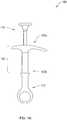
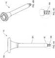
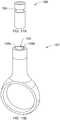
- Figures 1A-1Dshow front, side, top, and exploded views of an exemplary embodiment of a syringe system 100 used to house a syringe and needle assembly 101, which is fitted within the syringe system 100.
- the syringe system 100includes, among other features, a handle assembly 107 for allowing RA patients to grip the syringe system 100 comfortably, a plunger 110 for injecting the medication contained in the syringe system 100, and a needle tip cap 112 for shielding the needle assembly 101 fitted within the syringe system 100 protruding from the distal end 107b thereof.
- the plunger 110 and the needle tip cap 112are slidably engaged with respective proximal 107a and distal 107b ends of the handle assembly 107.
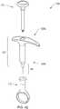
- Figure 1Eshows an alternative embodiment of a syringe system similar to those shown in Figures 1A-1D .
- the syringe system 120 as shown in Figure 1Eincludes, among other features, a handle assembly 122 having a proximal end 122a and a distal end 122b, and a needle tip cap 124.
- the handle assembly 122includes a curved hook 126 at one end that is shaped to facilitate the user's fingers to rest or anchor during use.
- the needle tip cap 124includes a tapering lip 128 that tapers from the interior edge 127 of the needle tip cap 124 to the exterior surface 130 of the needle tip cap 124.
- the needle tip cap 124includes an elliptical finger ring 132.
- the finger ring 132may be circular or other preferred shape that allows a user's finger or a hook to easily engage the needle tip cap 124.
- Figure 2Ashows an exploded view of the handle assembly 107, which includes a top cover 203 that is shaped to mate with a handle body 201.
- the handle body 201is unitary polycarbonate formed, for example, using injection molding.
- the handle body 201includes a gripping portion 204 fused, glued, or constructed continuously with a syringe barrel (portion) 106.
- a handgrip 102is formed when the top cover 203 is mated to the handle body 201 as shown in Figure 2A .
- the handgrip 102is contoured and has proportions to fit the hand of a patient with rheumatoid arthritis, in particular a hand of a patient that has the condition known as "Swan Neck Deformation.”
- the handgrip 102is also adapted to provide RA patients with various gripping options. Compared to a conventional hypodermic syringe, the handgrip 102 is generally larger and includes contoured gripping surfaces to allow RA patients with different syringe holding techniques to easily cradle the handgrip 102 in their hands.
- the handgrip 102is shaped to account for these situations when these patients are unable to control certain parts of their hand.
- the handgrip 102is also provided to improve engagement between the patient's hand and the syringe system 100.
- the top cover 203 and the gripping portion 204in certain embodiments, have different surface finishes, providing contrasting textures to enhance the patient's grip.
- the handgrip 102is made of rubbery or textured material, providing contact friction to enhance the patient's grip.
- the top cover 203includes a top aperture 205 for receiving the plunger 110 and a plurality of pegs 206a-206d for positioning and mating the top cover 203 to the gripping portion 204.
- Figure 2Bshows the underside of the top cover 203 having four pegs 206a-206d, which are shaped and sized to mate with corresponding depressions 208a-208d formed on the gripping portion 204.
- Figure 2Cshows a side view of the top cover 203.
- the pegs 206are symmetrically positioned with respect to the center axis of the top aperture 205.
- the top cover 203also includes a pair of mating pegs 207a-207b that mate with corresponding depressions 209a-209b formed on the gripping portion 204.
- the outer edge 211 of the top cover 203is rounded to provide smooth transition between the top cover 203 and the gripping portion 204 of the handle body 201.
- Figure 2Ddepicts a top view of the handle body 201 and an inside view of the distal surface of gripping portion 204.
- the handle body 201includes, among other things, a plurality of depressions 208a-208d that correspond to the pegs 206a-206d formed on the top cover 203 and a plurality of outer depressions 209a-209b shaped to receive the mating pegs 207a-207b formed on the top cover 203.
- the handle body 201also includes a bottom aperture 210 for receiving the plunger 110.
- the bottom aperture 210aligns with the top aperture 205 positioned on the top cover 203, thereby defining an orifice for receiving the plunger 110.
- the handle body 201also includes a recess lip 214 shaped to receive a mating surface 216 of the top cover 203.
- Figure 2Eshows a perspective view of the handle assembly 107 with the top cover 203 removed, which shows the recess lip 214 being formed along the periphery of the gripping portion 204 of the handle body 201.
- top cover 203mates with the handle body 201. Once mated, the top cover 203 and the handle body 201 together form a smooth handgrip 102. This configuration is beneficial to patients, as raised surfaces or sharp edges would be uncomfortable to the patients.
- the handle body 201also includes a syringe positioning pocket 212 having a flat side 212a. As shown in Figures 2D-2E , the syringe positioning pocket 212 includes two flat sides 212a disposed parallel and symmetrical about the longitudinal axis of the gripping portion 204 of the handle body 201. The syringe positioning pocket 212 aids in orienting a conventional syringe having dosage marks in a manner that makes it easier for the patients to read the dosage marks located on the syringe. More detailed description of the placement between the syringe having the dosage marks and the handle body 201 is provided with reference to Figures 5A-5B . Similar to the top cover 203, the outer edge 215 of the gripping portion 204 of the handle body 201 is also rounded and smoothed to maximize patient comfort.
- the handgrip 102is formed when the top cover 203 mates with the handle body 201.
- Figure 3Ashows the handgrip 102 having a first flange 102a and a second flange 102b.
- the first flange 102aincludes a first arc 204a formed from a bottom surface of the first flange 102a and is contoured to correspond to a radius of an arc formed by a patient's fingers.
- the second flange 102bincludes a second arc 204b formed from a bottom surface of the second flange 102b and having a contoured shape to correspond to the patient's fingers.
- the second arc 204bmay be approximately 1.5 times longer than the first arc 204a. In other embodiments, the second arc 204b is at least 2 times as long as the first arc 204a.
- the second arc 204bhas a flatter arc compared to the first arc 204a.
- Such shapeallows the patient to place more fingers around the second flange 102b and cradle the syringe 100 comfortably.
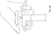
- Figure 3Ashows a patient holding the syringe using the patient's index and the third and fourth fingers. As shown, the patient's index finger is separated from the rest by the syringe barrel 106. In the depicted embodiment, the patient places his index finger against the first arc 204a and the third and fourth fingers against the second arc 204b.
- the first arc 204aincludes a first curved portion 205a that serves as an anchoring point when the patient is holding the syringe 100 to administer medication.
- the index fingerwhen the patient places the index finger against the first arc 204a, the index finger naturally wraps around the first curved portion 205a and the third finger fully or partially rests against a second curved portion 205b as shown in Figure 3A .
- the patient's index and the third fingersare also resting on the syringe barrel 106.
- Figures 3A-3Balso depict the positioning of the plunger 110 with respect to the handgrip 102.
- the handgrip 102is shaped to allow the patient's thumb to comfortably sit on the plunger 110.
- the plunger 110 as shown in Figure 4Aincludes, among other things, a concave plunger pad 302 located at the proximal end of the plunger 110 and a plunger stem 304 that extends from the concave plunger pad 302 to the distal tip of the plunger 110.
- the concave plunger pad 302is formed of a plastic with a rubber overmold.
- the concave plunger pad 302is shaped to receive the surface of the patient's thumb or other preferred finger(s) or parts of the patient's hand.
- Figure 3Ashows the base of the patient's thumb resting on the concave plunger pad 302.
- the patientprefers to place his palm on the concave plunger pad 302 for manipulating the plunger 110.
- Figure 3Bshows the patient using the base of his palm for pushing the plunger 110 for ejecting contained medicine.
- the shape of the concave plunger pad 302forms a depression for receiving the patient's finger or other parts of the patient's hand during the use of the syringe, which aids in preventing the patient's finger or hand from slipping from the top surface of the plunger pad 302, thereby making the self-injection safer.
- the plunger stem 304tapers from the concave plunger pad 302 and is structurally sturdier than commercially available plunger rods that incorporate a structure with an "X" or “T” cross section.
- the plunger stem 304is made of acrylonitrile butadiene styrene (ABS), other co-polymers, or other suitable light-weight material.
- ABSacrylonitrile butadiene styrene
- the plunger stem 304also includes a threaded portion 306 positioned at the distal end of the plunger stem 304. The threaded portion 306 threads into a stopper located in a syringe barrel of needle assembly 101 that contains the medicine.
- the stopperincludes corresponding female threads that receive the threaded portion 306 of the plunger stem 304 to provide secure engagement between the plunger 110 and the syringe barrel.
- Figure 4Cshows an enlarged view of the threaded portion 306 of the plunger 110.
- FIG. 5A-5Bdepict the needle assembly 101 fitted within the syringe system 100.
- needle assembly 101includes an inner barrel 404 fitted with a syringe needle 406.
- the inner barrel 404 of the needle assembly 101slides within the syringe barrel 106 of the handle assembly 107.
- the syringe barrel 106includes an aperture 408 shaped to allow the a distal end 404b of the inner barrel 404 to extend therethrough.
- the extended portion of the inner barrel 404includes a shoulder portion 405 and a distal tip portion 407.
- the shoulder portion 405tapers from the distal end 404b of the inner barrel to the distal tip portion 407 where a syringe needle 406 is embedded.
- the inner barrel 404, the shoulder portion 405, and the distal tip portion 407are made of glass and are formed as a unitary part.
- the inner barrel 404also includes dosage marks 410 that depict volumetric levels of medicament contained in the inner barrel 404.
- the aperture 408has a circular cross sectional area, as does the inner barrel 404.
- the two componentswhen the inner barrel 404 is fitted within the syringe barrel 106, the two components form a space having a ring shaped cross sectional area between the outer surface of the inner barrel 404 and the inner surface of the syringe barrel 106.
- the inner barrel 404includes proximal 404a and distal 404b ends and also an inner syringe barrel flange 412 having flat sides 412a and curved sides 412b formed on the proximal end 404a.
- the inner syringe barrel flange 412controls the orientation of the inner barrel 404 within the syringe barrel 106. This is done by placing the inner barrel 404 within the syringe barrel 106 so that the flat sides 412a of the inner syringe barrel flange 412 mate with the corresponding flat sides 212a of the syringe positioning pocket 212 located on the handle body 201.
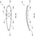
- Figures 6A-6B and 7depict various views of the handle body 201 having a major axis (or “diameter”) 422 and a minor axis (or “diameter”) 420 forming an oval cross section.
- the major axis 422is longer than the minor axis 420.
- the minor axis 420runs parallel to the length of the handgrip 102, such that the major axis 422 runs parallel and between the patient's fingers during administration and perpendicular to the longitudinal axis of the handgrip 102. This alignment provides stability to the syringe in the patient's hand during administration, which is believed to be beneficial for arthritic patients.
- This alignmentalso provides increased control to patients by providing greater contact surface area between the patient's fingers and the syringe 100. This is done by positioning the syringe 100 in the configuration as shown in Figure 7 . More specifically, the longer side (i.e., the major axis 422 running parallel to the patient's fingers) of the syringe barrel is positioned between the patient's fingers, which allows the syringe 100 to rotate less in patient's hand compared to a standard syringe having a circular cross-sectional area.
- the elliptical cross section of the syringe barrel 106also allows the syringe barrel 106 to fit more comfortably within the patient's hand for easier administration.
- the major axis 422is about 14.9 mm and the minor axis 420 is about 11.5 mm.
- the ratio of the length of major axis 422 to the length of the minor diameter 420is about 1.1:1, about 1.2:1, about 1.3:1, about 1.5:1, or even about 2:1.
- one of the objectives of the present syringe systemis to improve the visibility of the dosage marks for the patients.
- the dosage marks on the inner barrel 404are positioned at one end of the major axis 422. This places the dosage marks that are placed on the outer surface of the inner barrel 404 to project against a narrow end 424 ( Figure 7 ) of the syringe barrel 106, which causes magnification of the dosage marks such that a patient can read the dosage marks easier and more readily to determine the volume of medicament remaining in the inner barrel 404.
- FIG 8depicts a cross sectional view of the syringe system 100 as depicted in Figure 1A .
- the syringe system 100has a needle tip cap 112 with a proximal end engaged to the distal end of the handle assembly 107.
- the components that form the needle tip cap 112are next described with reference to Figures 9-13F .
- the interfitting relationship between the needle tip cap 112 and the handle assembly 107will be described with reference to Figure 16A-16B .
- needle tip cap 112includes an inner cap 602 that grips the needle assembly 101, a connector 604, and an outer cap 606.
- the connector 604receives the inner cap 602 and the outer cap 606 receives the connector 604 having the inner cap 602 enclosed within.
- the RA patientcan easily remove the needle tip cap 112 and expose the needle by simply pulling the outer cap 606 distally from the handle assembly 107.
- Figure 10Adepicts a perspective view of an exemplary embodiment of the inner cap 602.
- the inner cap 602is cylindrical in shape and includes a shoulder 902 in the proximal end.
- the inner cap 602may be made of rubbery material that allows a portion of the connector 604 to dig into the surface defined by the shoulder 902 to permanently engage the inner cap 602 to the connector 604.
- Figure 10Bshows a cross sectional view of the inner cap 602 as depicted in Figure 10A .
- the inner cap 602includes a needle receiving portion 904 that holds the tip of the needle as shown in Figure 8 .
- the needle receiving portion 904may be made from butadiene rubber.
- the inner cap 602is hollow.
- Figures 11A-Cshow various views of the connector 604 being inserted to the outer cap 606.
- the initially flower shaped connector 604as illustrated in Figure 13A , is bent so as to be confined within a cylindrical shaped stem 610 of the outer cap 606 ( Figure 12A ).
- a plurality of first legs 702a-702dwhich were initially disposed at about 80 degrees with respect to the horizontal are now about 90 degrees with respect to the horizontal.
- Figure 11Bshows upper internally facing barbs 703 protruding inwardly and distally to engage the inner cap 602 with a connection that tightens as the outer cap 606 is pulled distally. This connection prevents the inner cap 602 from being removed when a patient pulls on the outer cap 606 distally.
- Figure 11Cdepicts a top view of the connector 604 being inserted in the outer cap 606.
- the plurality of first legs 702a-702dengage the inner surface 605 of the outer cap 606 and the upper internally facing barbs 703 protrude inwardly and distally to engage the inner cap 602.
- Figure 11Calso shows the connector 604 including a second plurality of legs 706a-706b spaced symmetrically away from one another in the distal end of the connector 604.
- the second plurality of legs 706a-706bare initially disposed more than 90 degrees (e.g., about 91 degrees to about 120 degrees) with respect to the horizontal.
- the second plurality of legs 706a-706bmake contact with the inner surface 605 of the outer cap 606.
- the second plurality of legs 706a-706bdig into the inner surface 605 of the outer cap 606 and remain fixed in place during use.
- the outer cap 606includes a shoulder 608 and a stem 610 having a hollow inner space shaped to receive the connector 604, and a grip ring 612 shaped to receive a patient's finger.
- the shoulder 608includes an inner surface 622 and an outer surface 624 and flares outwardly and away from the stem 610, forming an orifice 618 (e.g., wider than the stem 610) into which the patient can re-insert the needle after injection.
- the orifice 618is wider than the distal end of the syringe barrel 106.
- the orifice 618envelopes the distal end of the syringe barrel 106 and the needle assembly 101 ( Figure 5A ).
- the interfitting relationship between the outer cap 606 and the syringe barrel 106is described with reference to Figures 16A-16B .
- the wider orificehelps reduce the likelihood that a patient will inadvertently stab his or her self when attempting to replace the needle cap after injection.
- the stem portion 610extends distally from the shoulder 608, which may have a cylindrical shape.
- Figure 12Bshows a cross sectional side view of the outer cap 606. As depicted, the orifice 618 flares outwardly from the stem 610 to a proximal end 620 of the outer cap 606.
- Figure 12Cshows a top view of the outer cap 606. As shown, the outer cap 606 is symmetrical about its center axis.
- the grip ring 612also has a finger aperture 614 to receive a patient's thumb or other preferred finger for pulling the needle tip cap 112 distally to expose the needle.
- the finger aperture 614is adapted to receive a hook that some patients use to pull the needle tip cap 112.
- the outer cap 606compared to a conventional needle covering cap, makes it easier for patients to engage and disengage the needle tip cover 112 from the syringe barrel 106 as it does not require the patient to contort their fingers by pressing on the sides of a narrow needle cap. As noted before, many patients have good and bad days and on bad days, some patients may experience difficulty pulling the needle cover off the syringe before self-injection.
- the grip ring 612addresses this issue by allowing the patient to simply put the thumb or other preferred finger through the finger aperture 614 and pull the needle tip cap 112.
- Figures 13A-13Fshow various views of the connector 604.
- the connector 604includes the first plurality of legs 702a -702d spaced symmetrically away from one another.
- the connector 604is made, in certain embodiments, from a thin sheet of stainless steel, formed by a tool that bends the first legs into angles with respect to the horizontal. Such configuration and the elastic nature of these legs aid in securing the inner cap 602 to the outer cap 606.
- the inner cap 602 and the outer cap 606are also secured together through upper, internally facing barbs 703a-703h protruding from the first legs 702a-702d.
- the upper, internally facing barbs 703a-703hinclude tips 704a-704p that point toward the distal end of the connector 604 (i.e., the needle end). As illustrated in Figures 13C and 13D , these barbs are spaced about the perimeter of the connector 604 near its proximal end, with each of the first legs (e.g., 702a) having two internally facing barbs (e.g., 703a-703b), and each barb containing a pair of barb tips (e.g., 704a-704b).
- the upper, internally facing barbs 703a-703hare concaved as shown in Figure 13A-13D . These barbs are shaped to engage the inner cap 602 when the inner cap 602 is fitted within the connector 604. More specifically, the barb tips (e.g., 704a and 704b) apply opposing force with respect to one another when they engage the inner cap 602 as the barb tips are disposed at two ends of a concaved surface (e.g., upper, internally facing barbs 703). In some embodiments, the upper, internally facing barbs 703a-703h are disposed at an angle with respect to the body of the first legs 702a-702d. This is more particularly shown in Figures 13D .
- Such configurationmay enhance the engagement between the inner cap 602 and the connector 604 as added protrusion (i.e., angled disposition of the barbs 703 with respect to the first legs 702) allows the barb tips 704a-704p to more securely dig into the inner cap 602 when a user pulls the needle tip cap 112 distally.
- the longitudinal axis 710 of the upper portion 711 of the first legs 702bis disposed at angle ⁇ with respect to the center axis 712 of the upper, internally facing barb 703c.
- the center axis 712may be disposed between about 3 degrees to about 30 degrees with respect to the longitudinal axis 710 of the first legs 702b.
- the connector 604contains a second plurality of legs 706a-706b spaced symmetrically away from one another in the distal end of the connector 604. As shown in Figure 13E , each of the second plurality of legs contains lower, externally facing barb tips 707a-707d that point toward the proximal end of the connector 604. These barbs engage a lower, interior portion of the outer cap 606, thereby barbing the connector 604 to the outer cap 606 in a manner similar to the connections between the upper, internally facing barb tips 704a-704p and the inner cap 602 as described above. As the lower barbs 707 extend proximally into the outer cap 606, these barbs 707 prevent, in combination with the upper, internally facing barb tips 704a-704p, the outer cap 606 from disengaging from the connector 604.
- Figures 14 and 15A-15Bdepict an exemplary mating relationship between various components of the needle tip cap 112. More specifically, these figures show the inner cap 602 being mated to the connector 604 and the connector 604 being mated to the outer cap 606. As shown, the connector 604 fits within the outer cap 606 and engages the inner cap 602, connecting substantially permanently to the inner cap 602, such that after engaged, if the outer cap 606 is pulled distally by the patient, the entire outer cap 606 and the inner cap 602 covering the needle are removed as a unit, exposing the needle.
- the inner cap 602is asymmetrical in shape, at least one pair of legs (e.g., 702a and 702c) makes contact with the inner cap 602 such that when the outer cap 606 is pulled, the entire outer cap 606 and the inner cap 602 would be removed as a unit. In some embodiments, only one but not both pairs of legs connect with the inner cap 602.
- at least one pair of legse.g., 702a and 702c
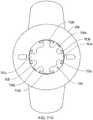
- Figure 14depicts a top view of the needle tip cap 112 having the inner cap 602 interfitted within the connector 604 and the assembly being fitted within the outer cap 606. As shown, only the outermost portions of the first plurality of legs 702a-702d are visible in the top view as the upper, internally facing barbs 703 have engaged the outer surface of the inner cap 602 and cannot be seen in the top view.
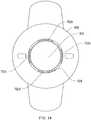
- Figure 15Adepicts a perspective view of the needle tip cap 112 as depicted in Figure 14 with the outer cap 606 removed for viewing clarity.
- the upper, internally facing barbs 703are adapted to receive the inner cap 602 when the inner cap 602 is being inserted onto the connector 604 in the direction indicated by the arrow ( Figure 15A ), but the upper, internally facing barb tips 704 are shaped to engage the inner cap 602 and prohibit backsliding of the inner cap 602 or removal of the connector 604 from the inner cap 602 once engaged.
- the upper barbs 703a-703hdig into the outer surface of the inner cap 602.
- Figure 15Bshows the externally facing barb tips 706a-706b engaging the distal region of the outer cap 606 in a manner similar to the connection between the upper, internally facing barb tips 704a-704p and the inner cap 602.
- the lower, externally facing barb tips 707a-707ddig into the inner surface of the outer cap 606.
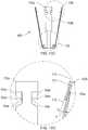
- the needle tip cap 112is designed to enclose the needle of the syringe system 100 and fittingly engage with the handle assembly 107. This engagement is shown in Figure 16A , where the orifice 618 (shown in Figure 12A ) of the needle tip cap 112 overlaps the needle assembly 404 that protrudes from the syringe barrel 106 and encloses the distal end of the handle assembly 107. More particularly, the tip cap 112 includes a plurality of mating protrusions 504a-504b formed on the inner surface 622 of the shoulder 608 ( Figure 12A ).
- the mating protrusion 504a and 504bengage with a pair of recesses 506a-506b positioned on the syringe barrel 106.
- the syringe barrel 106includes a major diameter and a minor diameter.
- the recess 506ais formed at one end of the major diameter and the recess 506b is formed at the opposite end of the major diameter.
- the protrusions 504a and 504b and the recesses 506a and 506bare shaped to allow a patient to engage and disengage the needle tip cap 112 with a minimal yet sufficient resistance to shield the needle.
- each of the mating protrusions 504a-504bincludes a top surface 510 and a side surface 512.
- the mating protrusions 504a-504bprotrude from the inner surface 622 at approximately 90 degrees so that the side surface 512 is positioned perpendicular to the longitudinal axis of the handle.
- the side portion 512 portionis also disposed perpendicularly to the top surface 510.
- the mating protrusions 504a-504bhave triangular cross-sectional area with sharp edges, which allows the mating protrusions to engage the recesses 506a-506b.
- the mating protrusionshave rounded edges.
- the recesses 506a-506binclude a proximal portion 514, a distal portion 516, and an inner mating surface 518 shaped to receive the side surfaces 512 of the mating protrusions 504a-504b.
- the distal portion 516flares outwardly to guide the mating protrusions 504a-504b and enable smoother engagement between the two components.
- the proximal portion 514forms a half-circle 520 shape that allows the edges of the top surface 510 to engage along the curved inner mating surface 518 of the proximal portion 514.
- the recesses 506a-506bare tapered from the proximal portion 514 to the distal portion 516.
- Aligning and mating the protrusions 504a-504b and the recesses 506a-506balso orients the needle tip cap 112 and the body of the syringe in the same plane, which aids in fitting the syringe system in commercial packaging, such as may be used in the sale of the biologic or other medicament.
- Figure 17Adepicts an alternative embodiment of the inner cap 1300 having a groove 1304 positioned near the proximal region of the inner cap 1300.
- the groove 1304runs along the circumference of the inner cap 1300 and is adapted to receive fittings 1306a-1306b located on the outer cap 1302 as shown in Figure 17B .
- the distal end of the inner cap 1300is inserted into the stem region 1306 of the outer cap 1302 and the fittings 1306a-1306b fit within the groove 1304 to secure the inner cap 1300 to the outer cap 1302.
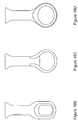
- FIGS 18A-18Ddepict alternative embodiments of the needle tip cap.
- the needle tip capmay be without a thumb ring that allows the patient's finger to engage the needle cap.
- a needle tip cap 1400 as shown in Figure 18Aincludes a proximal shoulder 1402 that flares outwardly to receive a needle, a holding surface 1404 for allowing the patient to hold and manipulate the needle tip cap 1400, and a distal shoulder 1406 that provides an anchoring place for patients to grab the needle tip cap 1400.
- the shape of the proximal shoulder 1402aids in preventing accidental needle stabs.
- the distal shoulder 1404includes a flat bottom surface that allows the needle tip cap 1400 to stand vertically on a flat surface, which may be helpful if the patient has difficulty grabbing small items laying horizontally flat on a surface.
- Figures 18B-18Ddepict alternative shapes for the thumb aperture for a needle tip cap.
- the patientpulls on the thumb aperture 614 ( Figure 12A ), thereby removing outer cap 606, the connector 604, and the inner cap 602 surrounding the needle to expose the entire needle for use.
- the patientis directed to hold the syringe in a way that is comfortable for the patient and insert the needle into the injection site at about 45 degrees to the skin.
- the patientthen pushes the plunger 110 until all the medicine is injected or other amount directed and pulls the needle out.
- the patientmay re-apply the needle tip cap 112 to the needle to protect against subsequent inadvertent injection, and discard.
- the syringe system 100is provided to the patient in a kit including a syringe, alcohol swab, and medication.
- syringe system 100is pre-filled with medication.
- Particular examplesinclude viscous medications containing proteins or peptides especially antibodies or fragments thereof, including pegylated antibody fragments.
- the systems and methodsmay in particular be used to administer the pegylated antibody fragment known as certolizumab pegol.
- the medicationmay be for treatment of any disease or disorder, including for the treatment of rheumatoid arthritis.
- the viscosity of the liquid medicationis less than about 120 mPa.s (120 centipoise), preferably less than 100 mPa.s (100 centipoise) at a delivery temperature of 20°C. In certain embodiments, the viscosity of the liquid medication is between about 65 centipoise and about 120 centipoise. In certain embodiments, the viscosity of the liquid medication is between about 75 centipoise and about 100 centipoise. In certain embodiments, the viscosity of the liquid medication is higher than about 65 mPa.s, preferably higher than 85 mPa.s.
- the viscosity of the liquid medicationis about 80 centipoise.
- the liquid medicationis designed for refrigerated rest (e.g. at from 2-8°C) and for injected delivery at room temperature (e.g. at or about 18-30°C).
Landscapes
- Health & Medical Sciences (AREA)
- Vascular Medicine (AREA)
- Engineering & Computer Science (AREA)
- Anesthesiology (AREA)
- Biomedical Technology (AREA)
- Heart & Thoracic Surgery (AREA)
- Hematology (AREA)
- Life Sciences & Earth Sciences (AREA)
- Animal Behavior & Ethology (AREA)
- General Health & Medical Sciences (AREA)
- Public Health (AREA)
- Veterinary Medicine (AREA)
- Infusion, Injection, And Reservoir Apparatuses (AREA)
- Acyclic And Carbocyclic Compounds In Medicinal Compositions (AREA)
Description
- This application claims the benefit of priority of United States provisional application serial number
61/010,779 filed January 11, 2008 61/135,262 filed July 18, 2008 61/192,551 filed September 18, 2008 - Rheumatoid arthritis ("RA") is an autoimmune disease characterized by chronic inflammation of the joints leading to progressive cartilage destruction and bone erosion. RA patients experience joint pain, stiffness, and swelling. More advanced RA causes the joint to lose its shape, alignment, and movement. RA has been treated for many years with a variety of medicines such as steroids and disease modifying antirheumatic drugs (DMARDs). Some of these drugs are administered through injections or infusions. However, it is difficult for RA patients with compromised joint strength and structure to manipulate available syringes to perform a self injection, particularly for viscous biologics and other drugs. Currently, some drugs are injected using conventional hypodermic syringes. These conventional syringes are generally small, which makes holding or manipulating the syringe more difficult. These syringes also do not provide RA patients with satisfactory handling and gripping structures.
- In addition, typical syringes are difficult for some patients to de-cap and recap. For example, most needles come with a needle tip cover that shields the needle prior to use, but the cover requires RA patients to force their fingers to close in around the needle tip cover to manipulate the cover. Because these needle tip covers have small openings, patients frequently accidentally stab themselves when they try to shield the needle after use.
- More effective syringe systems are needed to address these and other problems posed by currently available syringe systems. There is a need for a syringe system that allows the patient to more easily administer a viscous drug, yet still provide increased safety as well as increased control. There is also a need for syringe systems that provides more ergonomic gripping compatibility for RA patients.
US 4 743 234 A discloses a magnifier for hypodermic syringes that is adapted to fit closely on the cylindrical barrel of a syringe and which has an outer rounded surface which is polished and magnifies the numerals and lines on the syringe, with undercut opposing lips on a portion of the magnifier adapted to engage the barrel to removably secure the magnifier on the syringe and having a flat surface on the magnifier for advertising indicia and in at least one form, having a lock-like member engaged over the finger grip member on the syringe to secure the position of the magnifier on the syringe.US 2 586 581 A discloses an attachment for a syringe which is configured to be removably and slidably mounted on the syringe in superposed relation to the graduations. The attachment includes a magnification media and is therefore adapted for use by persons whose eyesight is impaired.WO 2005/115508 A1 discloses an injection device having a housing and a housing closure means. The injection device houses a syringe having a needle which is sealed by a boot. The housing closure means is arranged so that the boot can be connected to the housing closure means simply, but cannot be removed from the housing closure means. The housing and housing closure means are arranged so that upon rotation of the housing closure means, the housing closure means is moved axially away from the housing and the boot and the boot is removed from the syringe.FR 2 803 530 A1 claim 1. The document further discloses a syringe having finger stops in the form of a collar with two symmetrical halves separated by two diametrically opposed U-shaped recesses which act as locators for matching projections on a protective cap which fits over the plunger end of the syringe.US 2003/060777 A1 discloses an ergonomic syringe for use by an operator to inject fluid under pressure into a patient during a medical procedure. A large hand-grip and locations of finger grips, together with other features on these elements of the ergonomic syringe, are configured to increase comfort and reduce the fatigue, strain and risk of disability, which may be associated with achieving the force required for each injection to achieve the necessary high pressures.WO 00/35519 A1EP 0 372 892 A2 discloses a plastic syringe for use in dental medicine. The ergonomic shape of the body and piston cuff are adapted to allow for firmness and control over work execution inside the mouth.- According to one aspect of the present invention there is provided a tip cap as defined by
claim 1. According to another aspect of the present invention there is provided a syringe as defined by claim 5. - The syringe systems disclosed herein address various deficiencies in the prior art by, in various embodiments, providing improved syringe systems that allows patients to more easily administer medicine, particularly patients with, for example, compromised dexterity or joint strength. In one representative embodiment, a syringe system is provided with a handle having a first flange and a second flange that forms a handgrip. The handle also includes a first arc forming a bottom surface of the first flange contoured to correspond to a radius of an arc formed by a user's fingers and a second arc forming a bottom surface of the second flange contoured to correspond to a radius of an arc formed by the user's fingers and shaped flatter than the first arc. In certain embodiments, the second flange is 1.5 times as long as the first flange. The syringe system also includes a syringe barrel having an outer barrel and an inner barrel. The inner barrel includes dosage marks and a needle mounted at a distal end and the outer barrel is shaped to receive the inner barrel and has an elliptical cross section to magnify the dosage marks located on the inner barrel.
- The syringe system includes a tip cap slidably engageable with a distal end of the syringe barrel for shielding the needle, the tip cap having the features of
claim 1. The tip cap has an outer cap, an inner cap, and a connector. The connector is shaped to fit within and engage the outer cap and engage the inner cap and includes a plurality of first legs spaced symmetrically away from one another, each first leg having a plurality of internally facing barbs pointing toward a distal region of the connector and adapted to engage a proximal region of the inner cap. The plurality of internally facing barbs may be disposed at an angle with respect to the plurality of the first legs. The connector also includes a plurality of second legs spaced symmetrically away from one another, each second leg having a plurality of externally facing barbs located at the end of the second leg and adapted to engage a distal region of the outer cap. In certain embodiments, the plurality of first legs are biased initially at about 80 degrees with respect to the horizontal. - According to one implementation, the outer barrel includes a first recess and a second recess shaped to receive the tip cap. In certain embodiments, the outer cap includes a first protrusion and a second protrusion formed on an inner surface of a shoulder formed on the outer cap to interfit with the first recess and the second recess of the outer barrel, respectively In certain embodiments, the outer cap includes a gripping ring, which may be shaped to receive the user's thumb or other preferred finger to engage the ring. In certain embodiments, the gripping ring is shaped to receive a hook.
- According to one implementation, the outer barrel includes a distal aperture to allow the inner barrel to extend through the aperture. The outer barrel has a major diameter and a minor diameter. In certain embodiments, the major axis of the syringe barrel is longer than a minor axis of the syringe barrel. In certain embodiments, the ratio between the major diameter and the minor diameter is 1.5:1. In certain embodiments, the inner barrel is positioned within the outer barrel such that the dosage marks are oriented at one end of the major diameter for magnifying the dosage marks.
- According to one implementation, a syringe system includes a handle having a first flange and a second flange that forms a handgrip. The handle also includes a first arc forming a bottom surface of the first flange contoured to correspond to a radius of an arc formed by a user's fingers and a second arc forming a bottom surface of the second flange contoured to correspond to a radius of an arc formed by the user's fingers and shaped flatter than the first arc. The syringe system also includes a tip cap slidably engageable with a distal end of the syringe barrel for shielding the needle. In certain embodiments, the tip cap includes an outer cap, an inner cap, and a connector shaped to fit within and engage the outer cap and engage the inner cap and optionally includes a plurality of first legs spaced symmetrically away from one another, with each first leg having a plurality of internally facing barbs pointing toward a distal region of the connector and being adapted to engage a proximal region of the inner cap, where the plurality of internally facing barbs are disposed at an angle with respect to the plurality of first legs. The connector also includes a plurality of second legs spaced symmetrically away from one another, each second leg having a plurality of externally facing barbs located in the distal region of the connector and adapted to engage a distal region of the outer cap.
- According to one implementation, the syringe system includes a handle having a first flange and a second flange that forms a handgrip. The handle also includes a first arc forming a bottom surface of the first flange contoured to correspond to a radius of an arc formed by a user's fingers and a second arc forming a bottom surface of the second flange contoured to correspond to a radius of an arc formed by the user's fingers and shaped flatter than the first arc. The syringe system also includes a syringe barrel having an outer barrel and an inner barrel and extending distally from the handgrip, the inner barrel having dosage marks and a needle mounted at a distal end, and the outer barrel being shaped to receive the inner barrel and having an elliptical cross section to magnify the dosage marks located on the inner barrel. In certain embodiments, the handle of the syringe system includes a top cover and a handle body. The top cover includes a plurality of pegs adapted to mate with a set of corresponding depressions formed on the handle body. In certain embodiments the top cover includes an aperture for receiving a syringe plunger and the handle body includes an aperture for receiving a syringe plunger. In certain embodiments, the handle body includes a syringe positioning pocket having a flat side and the inner barrel includes a flange having a flat side adapted to align with corresponding flat sides formed on the handle body. In certain embodiments, aligning the flange within the syringe positioning pocket orients the dosage marks at one end of a major axis of the syringe barrel.
- According to one implementation, a syringe system includes a syringe barrel having an outer barrel and an inner barrel, the inner barrel having dosage marks and a needle mounted at a distal end. The outer barrel is shaped to receive the inner barrel and has an elliptical cross section to magnify the dosage marks located on the inner barrel.
- According to one implementation, a syringe barrel includes an outer barrel and an inner barrel. The inner barrel includes dosage marks and a needle mounted at a distal end and the outer barrel is shaped to receive the inner barrel and has an elliptical cross section to magnify the dosage marks located on the inner barrel.
- According to one implementation, a syringe system is disclosed as having a handle with a first flange and a second flange forming a handgrip, a first arc forming a bottom surface of the first flange contoured to correspond to a radius of an arc formed by a user's fingers and a second arc forming a bottom surface of the second flange contoured to correspond to a radius of an arc formed by the user's fingers and shaped flatter than the first arc. The syringe also includes a syringe barrel having an outer barrel and an inner barrel, the inner barrel having dosage marks and a needle mounted at a distal end, the outer barrel shaped to receive the inner barrel and having an elliptical cross section to magnify the dosage marks located on the inner barrel. The outer barrel includes proximal and distal ends and a recess formed at the distal end. In certain embodiments, the inner barrel is disposed within the tip cap when the tip cap mates with the outer barrel. In certain embodiments, the outer barrel has a distal opening and the inner barrel protrudes through the distal opening when the syringe assembly is fully assembled.
- According to one implementation, the outer barrel has a first recess and a second recess. The outer barrel also has a major diameter and a minor diameter, and the first recess is formed at first end of the major diameter and the second recess is formed at an opposite end of the major diameter. The mating protrusion of the tip cap includes a top surface and a side surface, the side surface being positioned perpendicular to the longitudinal axis of the handle. In certain embodiments, the mating protrusion has a triangular cross sectional area. The syringe also includes a tip cap that includes an inner cap, an outer cap, and a connector shaped to fit within and engage the outer cap and engage the inner cap.
- In certain embodiments, the tip cap includes a stem portion extending distally from the shoulder having a cylindrical shape. The inner cap and the connector are received within the stem portion.
- These and other features and advantages of the invention are described in further detail below with regard to illustrative embodiments.
- The following Figures depict illustrative embodiments of the invention in which like reference numerals refer to like elements. These depicted embodiments may not be drawn to scale and are to be understood as illustrative and not limiting.
Figures 1A - 1D depict various views of a syringe system according to an illustrative embodiment of the invention.Figure 1E depicts an alternative embodiment of a syringe system.Figure 2A depicts an exploded view of a handle assembly of the syringe system depicted inFigures 1A-1D .Figures 2B-2C depict underside and side views of an exemplary embodiment of a top cover of the handle assembly as depicted inFigure 2A .Figure 2D shows a top view of an exemplary embodiment of the handle assembly as depicted inFigure 2A .Figure 2E depicts a perspective view of a handle body as depicted inFigure 2A .Figures 3A-3B show a patient holding the handle assembly having a plunger according to an illustrative embodiment of the invention.Figures 4A-4C depict various views of a plunger as depicted inFigures 1A-1D .Figure 5A depicts an inner barrel received in the handle assembly and the plunger being partially received within the inner barrel according to an illustrative embodiment of the invention.Figure 5B depicts a perspective view of an exemplary embodiment of the inner barrel of the syringe system as depicted inFigure 5A .Figures 6A-6B depict front and side views of the handle assembly as depicted inFigure 2A .Figure 7 depicts a patient holding the handle assembly between the patient's index and the third finger of the patient's left hand.Figure 8 depicts a cross-section view of the syringe system as depicted inFigures 1A-1B .Figure 9 depicts an exploded view of a needle tip cap as depicted inFigure 8 showing an exemplary mating relationships between an inner cap, a connector, and an outer cap.Figures 10A-10B depict perspective and cross sectional view of an exemplary embodiment of the inner cap as depicted inFigures 8 .Figures 11A-11C depict various views of an exemplary embodiment of the connector being mated to the outer cap as depicted inFigure 8 .Figures 12A - 12C depict various views of an exemplary embodiment of the outer cap as depicted inFigure 9 .Figures 13A-13F depict various views of an exemplary embodiment of the connector for connecting the inner cap to the outer cap as depicted inFigure 8 .Figure 14 depicts a top view of an exemplary embodiment of a needle tip cap having the inner cap, the connector, and the outer cap as depicted inFigure 8 .Figure 15A depicts a perspective view of the needle tip cap as depicted inFigure 14 with the outer cap removed for viewing clarityFigure 15B depicts a cross sectional view of a connector being received within the outer cap.Figure 16A depicts an exploded view of the needle tip cap mating to the handle assembly having the plunger according to an illustrative embodiment of the invention.Figure 16B depicts an enlarged view of a distal region of the handle assembly as shown inFigure 16A .Figure 17A depicts an alternative embodiment of an inner cap.Figure 17B depicts an alternative embodiment of a needle tip cap adapted to mate with the inner cap as depicted inFigure 17A .Figures 18A-18D depict alternative embodiments of a needle tip cap.- To provide an overall understanding of the invention, certain illustrative embodiments will now be described, including exemplary embodiments of a system that is adaptable to inject liquid drugs in the treatment of a patient suffering RA or other auto-immune diseases such as Multiple Sclerosis, Lupus, and Spondylitis. However, it will be understood by one of ordinary skill in the art that the systems and methods described herein can be adapted and modified for other suitable applications and that such other additions and modifications will not depart from the scope hereof.
- Turning to the illustrative embodiments,
Figures 1A-1D show front, side, top, and exploded views of an exemplary embodiment of asyringe system 100 used to house a syringe andneedle assembly 101, which is fitted within thesyringe system 100. Thesyringe system 100 includes, among other features, ahandle assembly 107 for allowing RA patients to grip thesyringe system 100 comfortably, aplunger 110 for injecting the medication contained in thesyringe system 100, and aneedle tip cap 112 for shielding theneedle assembly 101 fitted within thesyringe system 100 protruding from thedistal end 107b thereof. Theplunger 110 and theneedle tip cap 112 are slidably engaged with respective proximal 107a and distal 107b ends of thehandle assembly 107. Figure 1E shows an alternative embodiment of a syringe system similar to those shown inFigures 1A-1D . In particular, thesyringe system 120 as shown inFigure 1E includes, among other features, ahandle assembly 122 having aproximal end 122a and adistal end 122b, and aneedle tip cap 124. As shown, thehandle assembly 122 includes acurved hook 126 at one end that is shaped to facilitate the user's fingers to rest or anchor during use. Theneedle tip cap 124 includes a taperinglip 128 that tapers from theinterior edge 127 of theneedle tip cap 124 to theexterior surface 130 of theneedle tip cap 124. In the depicted embodiment, theneedle tip cap 124 includes anelliptical finger ring 132. Thefinger ring 132 may be circular or other preferred shape that allows a user's finger or a hook to easily engage theneedle tip cap 124.Figure 2A shows an exploded view of thehandle assembly 107, which includes atop cover 203 that is shaped to mate with ahandle body 201. In the depicted embodiment, thehandle body 201 is unitary polycarbonate formed, for example, using injection molding. Thehandle body 201 includes agripping portion 204 fused, glued, or constructed continuously with a syringe barrel (portion) 106.- A
handgrip 102 is formed when thetop cover 203 is mated to thehandle body 201 as shown inFigure 2A . Thehandgrip 102 is contoured and has proportions to fit the hand of a patient with rheumatoid arthritis, in particular a hand of a patient that has the condition known as "Swan Neck Deformation." Thehandgrip 102 is also adapted to provide RA patients with various gripping options. Compared to a conventional hypodermic syringe, thehandgrip 102 is generally larger and includes contoured gripping surfaces to allow RA patients with different syringe holding techniques to easily cradle thehandgrip 102 in their hands. This is helpful to RA patients because they have "good days" and "bad days" in terms of the amount of pain and the control that they have over their joints. On bad days, a patient might not be able to hold the syringe the way he or she normally does. Thehandgrip 102 is shaped to account for these situations when these patients are unable to control certain parts of their hand. Thehandgrip 102 is also provided to improve engagement between the patient's hand and thesyringe system 100. Thetop cover 203 and thegripping portion 204, in certain embodiments, have different surface finishes, providing contrasting textures to enhance the patient's grip. In other embodiments, thehandgrip 102 is made of rubbery or textured material, providing contact friction to enhance the patient's grip. - The
top cover 203 includes atop aperture 205 for receiving theplunger 110 and a plurality ofpegs 206a-206d for positioning and mating thetop cover 203 to thegripping portion 204.Figure 2B shows the underside of thetop cover 203 having fourpegs 206a-206d, which are shaped and sized to mate with corresponding depressions 208a-208d formed on thegripping portion 204.Figure 2C shows a side view of thetop cover 203. In the depicted embodiments, the pegs 206 are symmetrically positioned with respect to the center axis of thetop aperture 205. Thetop cover 203 also includes a pair ofmating pegs 207a-207b that mate with correspondingdepressions 209a-209b formed on thegripping portion 204. Theouter edge 211 of thetop cover 203 is rounded to provide smooth transition between thetop cover 203 and thegripping portion 204 of thehandle body 201. Figure 2D depicts a top view of thehandle body 201 and an inside view of the distal surface of grippingportion 204. As shown, thehandle body 201 includes, among other things, a plurality ofdepressions 208a-208d that correspond to thepegs 206a-206d formed on thetop cover 203 and a plurality ofouter depressions 209a-209b shaped to receive the mating pegs 207a-207b formed on thetop cover 203. Thehandle body 201 also includes abottom aperture 210 for receiving theplunger 110. When the pegs 206 and 207 of thetop cover 203 mate with the depressions 208 and 209 of thehandle body 201, respectively, thebottom aperture 210 aligns with thetop aperture 205 positioned on thetop cover 203, thereby defining an orifice for receiving theplunger 110. Thehandle body 201 also includes arecess lip 214 shaped to receive amating surface 216 of thetop cover 203.Figure 2E shows a perspective view of thehandle assembly 107 with thetop cover 203 removed, which shows therecess lip 214 being formed along the periphery of thegripping portion 204 of thehandle body 201. Having therecess lip 214 avoids thehandgrip 102 having sharp or protruded edges when thetop cover 203 mates with thehandle body 201. Once mated, thetop cover 203 and thehandle body 201 together form asmooth handgrip 102. This configuration is beneficial to patients, as raised surfaces or sharp edges would be uncomfortable to the patients.- The
handle body 201 also includes asyringe positioning pocket 212 having aflat side 212a. As shown inFigures 2D-2E , thesyringe positioning pocket 212 includes twoflat sides 212a disposed parallel and symmetrical about the longitudinal axis of thegripping portion 204 of thehandle body 201. Thesyringe positioning pocket 212 aids in orienting a conventional syringe having dosage marks in a manner that makes it easier for the patients to read the dosage marks located on the syringe. More detailed description of the placement between the syringe having the dosage marks and thehandle body 201 is provided with reference toFigures 5A-5B . Similar to thetop cover 203, theouter edge 215 of thegripping portion 204 of thehandle body 201 is also rounded and smoothed to maximize patient comfort. - As noted earlier, the
handgrip 102 is formed when thetop cover 203 mates with thehandle body 201.Figure 3A shows thehandgrip 102 having afirst flange 102a and asecond flange 102b. Thefirst flange 102a includes afirst arc 204a formed from a bottom surface of thefirst flange 102a and is contoured to correspond to a radius of an arc formed by a patient's fingers. Similarly, thesecond flange 102b includes asecond arc 204b formed from a bottom surface of thesecond flange 102b and having a contoured shape to correspond to the patient's fingers. Thesecond arc 204b may be approximately 1.5 times longer than thefirst arc 204a. In other embodiments, thesecond arc 204b is at least 2 times as long as thefirst arc 204a. - In some embodiments, the
second arc 204b has a flatter arc compared to thefirst arc 204a. Such shape allows the patient to place more fingers around thesecond flange 102b and cradle thesyringe 100 comfortably. For example,Figure 3A shows a patient holding the syringe using the patient's index and the third and fourth fingers. As shown, the patient's index finger is separated from the rest by thesyringe barrel 106. In the depicted embodiment, the patient places his index finger against thefirst arc 204a and the third and fourth fingers against thesecond arc 204b. Thefirst arc 204a includes a firstcurved portion 205a that serves as an anchoring point when the patient is holding thesyringe 100 to administer medication. Using the example above, when the patient places the index finger against thefirst arc 204a, the index finger naturally wraps around the firstcurved portion 205a and the third finger fully or partially rests against a secondcurved portion 205b as shown inFigure 3A . The patient's index and the third fingers are also resting on thesyringe barrel 106. Figures 3A-3B also depict the positioning of theplunger 110 with respect to thehandgrip 102. As shown inFigure 3A , thehandgrip 102 is shaped to allow the patient's thumb to comfortably sit on theplunger 110. Theplunger 110 as shown inFigure 4A includes, among other things, aconcave plunger pad 302 located at the proximal end of theplunger 110 and aplunger stem 304 that extends from theconcave plunger pad 302 to the distal tip of theplunger 110. Theconcave plunger pad 302 is formed of a plastic with a rubber overmold. Theconcave plunger pad 302 is shaped to receive the surface of the patient's thumb or other preferred finger(s) or parts of the patient's hand.Figure 3A shows the base of the patient's thumb resting on theconcave plunger pad 302. In some embodiments, the patient prefers to place his palm on theconcave plunger pad 302 for manipulating theplunger 110.Figure 3B shows the patient using the base of his palm for pushing theplunger 110 for ejecting contained medicine. The shape of theconcave plunger pad 302 forms a depression for receiving the patient's finger or other parts of the patient's hand during the use of the syringe, which aids in preventing the patient's finger or hand from slipping from the top surface of theplunger pad 302, thereby making the self-injection safer.- As shown in
Figures 4A-4B , theplunger stem 304, having a circular cross section, tapers from theconcave plunger pad 302 and is structurally sturdier than commercially available plunger rods that incorporate a structure with an "X" or "T" cross section. In certain embodiments, theplunger stem 304 is made of acrylonitrile butadiene styrene (ABS), other co-polymers, or other suitable light-weight material. The plunger stem 304 also includes a threadedportion 306 positioned at the distal end of theplunger stem 304. The threadedportion 306 threads into a stopper located in a syringe barrel ofneedle assembly 101 that contains the medicine. The stopper includes corresponding female threads that receive the threadedportion 306 of theplunger stem 304 to provide secure engagement between theplunger 110 and the syringe barrel.Figure 4C shows an enlarged view of the threadedportion 306 of theplunger 110. Figure 5A-5B depict theneedle assembly 101 fitted within thesyringe system 100. In particular,needle assembly 101 includes aninner barrel 404 fitted with asyringe needle 406. As shown inFigure 5A , theinner barrel 404 of theneedle assembly 101 slides within thesyringe barrel 106 of thehandle assembly 107. As depicted, thesyringe barrel 106 includes anaperture 408 shaped to allow the adistal end 404b of theinner barrel 404 to extend therethrough. The extended portion of theinner barrel 404 includes ashoulder portion 405 and adistal tip portion 407. Theshoulder portion 405 tapers from thedistal end 404b of the inner barrel to thedistal tip portion 407 where asyringe needle 406 is embedded. In certain embodiments, theinner barrel 404, theshoulder portion 405, and thedistal tip portion 407 are made of glass and are formed as a unitary part. Theinner barrel 404 also includes dosage marks 410 that depict volumetric levels of medicament contained in theinner barrel 404. In the depicted embodiment, theaperture 408 has a circular cross sectional area, as does theinner barrel 404. In certain embodiments, when theinner barrel 404 is fitted within thesyringe barrel 106, the two components form a space having a ring shaped cross sectional area between the outer surface of theinner barrel 404 and the inner surface of thesyringe barrel 106.- As more particularly illustrated in
Figure 5B , theinner barrel 404 includes proximal 404a and distal 404b ends and also an innersyringe barrel flange 412 havingflat sides 412a andcurved sides 412b formed on theproximal end 404a. In certain embodiments, the innersyringe barrel flange 412 controls the orientation of theinner barrel 404 within thesyringe barrel 106. This is done by placing theinner barrel 404 within thesyringe barrel 106 so that theflat sides 412a of the innersyringe barrel flange 412 mate with the correspondingflat sides 212a of thesyringe positioning pocket 212 located on thehandle body 201. Figures 6A-6B and7 depict various views of thehandle body 201 having a major axis (or "diameter") 422 and a minor axis (or "diameter") 420 forming an oval cross section. Themajor axis 422 is longer than theminor axis 420. Theminor axis 420 runs parallel to the length of thehandgrip 102, such that themajor axis 422 runs parallel and between the patient's fingers during administration and perpendicular to the longitudinal axis of thehandgrip 102. This alignment provides stability to the syringe in the patient's hand during administration, which is believed to be beneficial for arthritic patients. This alignment also provides increased control to patients by providing greater contact surface area between the patient's fingers and thesyringe 100. This is done by positioning thesyringe 100 in the configuration as shown inFigure 7 . More specifically, the longer side (i.e., themajor axis 422 running parallel to the patient's fingers) of the syringe barrel is positioned between the patient's fingers, which allows thesyringe 100 to rotate less in patient's hand compared to a standard syringe having a circular cross-sectional area. The elliptical cross section of thesyringe barrel 106 also allows thesyringe barrel 106 to fit more comfortably within the patient's hand for easier administration. In certain embodiments, themajor axis 422 is about 14.9 mm and theminor axis 420 is about 11.5 mm. In certain embodiments, the ratio of the length ofmajor axis 422 to the length of theminor diameter 420 is about 1.1:1, about 1.2:1, about 1.3:1, about 1.5:1, or even about 2:1.- As noted earlier, one of the objectives of the present syringe system is to improve the visibility of the dosage marks for the patients. When the
inner barrel 404 is placed within thesyringe barrel 106 as shown inFigures 6A-6B and7 , the dosage marks on theinner barrel 404 are positioned at one end of themajor axis 422. This places the dosage marks that are placed on the outer surface of theinner barrel 404 to project against a narrow end 424 (Figure 7 ) of thesyringe barrel 106, which causes magnification of the dosage marks such that a patient can read the dosage marks easier and more readily to determine the volume of medicament remaining in theinner barrel 404. - In addition to improved handle and plunger features discussed above, improved syringe cap removal systems are also disclosed herein. An illustrative embodiment of a needle tip cap is shown in
Figure 8 , which depicts a cross sectional view of thesyringe system 100 as depicted inFigure 1A . As shown, thesyringe system 100 has aneedle tip cap 112 with a proximal end engaged to the distal end of thehandle assembly 107. The components that form theneedle tip cap 112 are next described with reference toFigures 9-13F . The interfitting relationship between theneedle tip cap 112 and thehandle assembly 107 will be described with reference toFigure 16A-16B . - As shown in
Figure 9 ,needle tip cap 112 includes aninner cap 602 that grips theneedle assembly 101, aconnector 604, and anouter cap 606. Theconnector 604 receives theinner cap 602 and theouter cap 606 receives theconnector 604 having theinner cap 602 enclosed within. In use, the RA patient can easily remove theneedle tip cap 112 and expose the needle by simply pulling theouter cap 606 distally from thehandle assembly 107. Figure 10A depicts a perspective view of an exemplary embodiment of theinner cap 602. As shown, theinner cap 602 is cylindrical in shape and includes ashoulder 902 in the proximal end. Theinner cap 602 may be made of rubbery material that allows a portion of theconnector 604 to dig into the surface defined by theshoulder 902 to permanently engage theinner cap 602 to theconnector 604.Figure 10B shows a cross sectional view of theinner cap 602 as depicted inFigure 10A . As depicted, theinner cap 602 includes aneedle receiving portion 904 that holds the tip of the needle as shown inFigure 8 . Theneedle receiving portion 904 may be made from butadiene rubber. In certain embodiments, theinner cap 602 is hollow.Figures 11A-C show various views of theconnector 604 being inserted to theouter cap 606. As shown, the initially flower shapedconnector 604, as illustrated inFigure 13A , is bent so as to be confined within a cylindrical shapedstem 610 of the outer cap 606 (Figure 12A ). As a result, a plurality offirst legs 702a-702d, which were initially disposed at about 80 degrees with respect to the horizontal are now about 90 degrees with respect to the horizontal.Figure 11B shows upper internally facingbarbs 703 protruding inwardly and distally to engage theinner cap 602 with a connection that tightens as theouter cap 606 is pulled distally. This connection prevents theinner cap 602 from being removed when a patient pulls on theouter cap 606 distally.Figure 11C depicts a top view of theconnector 604 being inserted in theouter cap 606. As shown, when theconnector 604 is fitted within theouter cap 606, the plurality offirst legs 702a-702d engage theinner surface 605 of theouter cap 606 and the upper internally facingbarbs 703 protrude inwardly and distally to engage theinner cap 602.Figure 11C also shows theconnector 604 including a second plurality oflegs 706a-706b spaced symmetrically away from one another in the distal end of theconnector 604. In some embodiments, the second plurality oflegs 706a-706b are initially disposed more than 90 degrees (e.g., about 91 degrees to about 120 degrees) with respect to the horizontal. When theconnector 604 is fitted within theouter cap 606, the second plurality oflegs 706a-706b make contact with theinner surface 605 of theouter cap 606. In some embodiments, the second plurality oflegs 706a-706b dig into theinner surface 605 of theouter cap 606 and remain fixed in place during use.- The various components of the
needle tip cap 112 are more particularly described with reference toFigure 12A-13F . As shown inFigure 12A , theouter cap 606 includes ashoulder 608 and astem 610 having a hollow inner space shaped to receive theconnector 604, and agrip ring 612 shaped to receive a patient's finger. Theshoulder 608 includes aninner surface 622 and anouter surface 624 and flares outwardly and away from thestem 610, forming an orifice 618 (e.g., wider than the stem 610) into which the patient can re-insert the needle after injection. As shown, theorifice 618 is wider than the distal end of thesyringe barrel 106. In some embodiments, theorifice 618 envelopes the distal end of thesyringe barrel 106 and the needle assembly 101 (Figure 5A ). The interfitting relationship between theouter cap 606 and thesyringe barrel 106 is described with reference toFigures 16A-16B . The wider orifice helps reduce the likelihood that a patient will inadvertently stab his or her self when attempting to replace the needle cap after injection. Thestem portion 610 extends distally from theshoulder 608, which may have a cylindrical shape.Figure 12B shows a cross sectional side view of theouter cap 606. As depicted, theorifice 618 flares outwardly from thestem 610 to aproximal end 620 of theouter cap 606.Figure 12C shows a top view of theouter cap 606. As shown, theouter cap 606 is symmetrical about its center axis. - The
grip ring 612 also has afinger aperture 614 to receive a patient's thumb or other preferred finger for pulling theneedle tip cap 112 distally to expose the needle. In certain embodiments, thefinger aperture 614 is adapted to receive a hook that some patients use to pull theneedle tip cap 112. Theouter cap 606, compared to a conventional needle covering cap, makes it easier for patients to engage and disengage theneedle tip cover 112 from thesyringe barrel 106 as it does not require the patient to contort their fingers by pressing on the sides of a narrow needle cap. As noted before, many patients have good and bad days and on bad days, some patients may experience difficulty pulling the needle cover off the syringe before self-injection. Thegrip ring 612 addresses this issue by allowing the patient to simply put the thumb or other preferred finger through thefinger aperture 614 and pull theneedle tip cap 112. Figures 13A-13F show various views of theconnector 604. As shown inFigure 13A , theconnector 604 includes the first plurality oflegs 702a -702d spaced symmetrically away from one another. Theconnector 604 is made, in certain embodiments, from a thin sheet of stainless steel, formed by a tool that bends the first legs into angles with respect to the horizontal. Such configuration and the elastic nature of these legs aid in securing theinner cap 602 to theouter cap 606.- The
inner cap 602 and theouter cap 606 are also secured together through upper, internally facingbarbs 703a-703h protruding from thefirst legs 702a-702d. The upper, internally facingbarbs 703a-703h includetips 704a-704p that point toward the distal end of the connector 604 (i.e., the needle end). As illustrated inFigures 13C and 13D , these barbs are spaced about the perimeter of theconnector 604 near its proximal end, with each of the first legs (e.g., 702a) having two internally facing barbs (e.g., 703a-703b), and each barb containing a pair of barb tips (e.g., 704a-704b). In some embodiments, the upper, internally facingbarbs 703a-703h are concaved as shown inFigure 13A-13D . These barbs are shaped to engage theinner cap 602 when theinner cap 602 is fitted within theconnector 604. More specifically, the barb tips (e.g., 704a and 704b) apply opposing force with respect to one another when they engage theinner cap 602 as the barb tips are disposed at two ends of a concaved surface (e.g., upper, internally facing barbs 703). In some embodiments, the upper, internally facingbarbs 703a-703h are disposed at an angle with respect to the body of thefirst legs 702a-702d. This is more particularly shown inFigures 13D . Such configuration may enhance the engagement between theinner cap 602 and theconnector 604 as added protrusion (i.e., angled disposition of thebarbs 703 with respect to the first legs 702) allows thebarb tips 704a-704p to more securely dig into theinner cap 602 when a user pulls theneedle tip cap 112 distally. As depicted inFigure 13D , thelongitudinal axis 710 of theupper portion 711 of thefirst legs 702b is disposed at angle α with respect to thecenter axis 712 of the upper, internally facingbarb 703c. Thecenter axis 712 may be disposed between about 3 degrees to about 30 degrees with respect to thelongitudinal axis 710 of thefirst legs 702b. - As noted above, the
connector 604 contains a second plurality oflegs 706a-706b spaced symmetrically away from one another in the distal end of theconnector 604. As shown inFigure 13E , each of the second plurality of legs contains lower, externally facingbarb tips 707a-707d that point toward the proximal end of theconnector 604. These barbs engage a lower, interior portion of theouter cap 606, thereby barbing theconnector 604 to theouter cap 606 in a manner similar to the connections between the upper, internally facingbarb tips 704a-704p and theinner cap 602 as described above. As the lower barbs 707 extend proximally into theouter cap 606, these barbs 707 prevent, in combination with the upper, internally facingbarb tips 704a-704p, theouter cap 606 from disengaging from theconnector 604. Figures 14 and15A-15B depict an exemplary mating relationship between various components of theneedle tip cap 112. More specifically, these figures show theinner cap 602 being mated to theconnector 604 and theconnector 604 being mated to theouter cap 606. As shown, theconnector 604 fits within theouter cap 606 and engages theinner cap 602, connecting substantially permanently to theinner cap 602, such that after engaged, if theouter cap 606 is pulled distally by the patient, the entireouter cap 606 and theinner cap 602 covering the needle are removed as a unit, exposing the needle. In some embodiments theinner cap 602 is asymmetrical in shape, at least one pair of legs (e.g., 702a and 702c) makes contact with theinner cap 602 such that when theouter cap 606 is pulled, the entireouter cap 606 and theinner cap 602 would be removed as a unit. In some embodiments, only one but not both pairs of legs connect with theinner cap 602.Figure 14 depicts a top view of theneedle tip cap 112 having theinner cap 602 interfitted within theconnector 604 and the assembly being fitted within theouter cap 606. As shown, only the outermost portions of the first plurality oflegs 702a-702d are visible in the top view as the upper, internally facingbarbs 703 have engaged the outer surface of theinner cap 602 and cannot be seen in the top view.Figure 15A depicts a perspective view of theneedle tip cap 112 as depicted inFigure 14 with theouter cap 606 removed for viewing clarity. The upper, internally facingbarbs 703 are adapted to receive theinner cap 602 when theinner cap 602 is being inserted onto theconnector 604 in the direction indicated by the arrow (Figure 15A ), but the upper, internally facing barb tips 704 are shaped to engage theinner cap 602 and prohibit backsliding of theinner cap 602 or removal of theconnector 604 from theinner cap 602 once engaged. As shown, once engaged, theupper barbs 703a-703h dig into the outer surface of theinner cap 602.Figure 15B shows the externally facingbarb tips 706a-706b engaging the distal region of theouter cap 606 in a manner similar to the connection between the upper, internally facingbarb tips 704a-704p and theinner cap 602. In some embodiments, the lower, externally facingbarb tips 707a-707d dig into the inner surface of theouter cap 606.- As explained above, the
needle tip cap 112 is designed to enclose the needle of thesyringe system 100 and fittingly engage with thehandle assembly 107. This engagement is shown inFigure 16A , where the orifice 618 (shown inFigure 12A ) of theneedle tip cap 112 overlaps theneedle assembly 404 that protrudes from thesyringe barrel 106 and encloses the distal end of thehandle assembly 107. More particularly, thetip cap 112 includes a plurality ofmating protrusions 504a-504b formed on theinner surface 622 of the shoulder 608 (Figure 12A ). Themating protrusion syringe barrel 106. As explained above, thesyringe barrel 106 includes a major diameter and a minor diameter. In certain embodiments, the recess 506a is formed at one end of the major diameter and the recess 506b is formed at the opposite end of the major diameter. Theprotrusions needle tip cap 112 with a minimal yet sufficient resistance to shield the needle. As shown, each of themating protrusions 504a-504b includes atop surface 510 and aside surface 512. As depicted inFigures 12A , themating protrusions 504a-504b protrude from theinner surface 622 at approximately 90 degrees so that theside surface 512 is positioned perpendicular to the longitudinal axis of the handle. Theside portion 512 portion is also disposed perpendicularly to thetop surface 510. In some embodiments, themating protrusions 504a-504b have triangular cross-sectional area with sharp edges, which allows the mating protrusions to engage the recesses 506a-506b. In certain embodiments, the mating protrusions have rounded edges. - As depicted in
Figure 16B , the recesses 506a-506b include aproximal portion 514, adistal portion 516, and aninner mating surface 518 shaped to receive the side surfaces 512 of themating protrusions 504a-504b. As shown, thedistal portion 516 flares outwardly to guide themating protrusions 504a-504b and enable smoother engagement between the two components. As depicted, theproximal portion 514 forms a half-circle 520 shape that allows the edges of thetop surface 510 to engage along the curvedinner mating surface 518 of theproximal portion 514. In some embodiments, the recesses 506a-506b are tapered from theproximal portion 514 to thedistal portion 516. - Aligning and mating the
protrusions 504a-504b and the recesses 506a-506b also orients theneedle tip cap 112 and the body of the syringe in the same plane, which aids in fitting the syringe system in commercial packaging, such as may be used in the sale of the biologic or other medicament. Figure 17A depicts an alternative embodiment of theinner cap 1300 having agroove 1304 positioned near the proximal region of theinner cap 1300. As depicted, thegroove 1304 runs along the circumference of theinner cap 1300 and is adapted to receivefittings 1306a-1306b located on theouter cap 1302 as shown inFigure 17B . When assembled, the distal end of theinner cap 1300 is inserted into thestem region 1306 of theouter cap 1302 and thefittings 1306a-1306b fit within thegroove 1304 to secure theinner cap 1300 to theouter cap 1302.Figures 18A-18D depict alternative embodiments of the needle tip cap. As illustrated, the needle tip cap may be without a thumb ring that allows the patient's finger to engage the needle cap. Aneedle tip cap 1400 as shown inFigure 18A includes aproximal shoulder 1402 that flares outwardly to receive a needle, a holdingsurface 1404 for allowing the patient to hold and manipulate theneedle tip cap 1400, and adistal shoulder 1406 that provides an anchoring place for patients to grab theneedle tip cap 1400. The shape of theproximal shoulder 1402 aids in preventing accidental needle stabs. As depicted, thedistal shoulder 1404 includes a flat bottom surface that allows theneedle tip cap 1400 to stand vertically on a flat surface, which may be helpful if the patient has difficulty grabbing small items laying horizontally flat on a surface.Figures 18B-18D depict alternative shapes for the thumb aperture for a needle tip cap.- To use the syringe for injection, the patient pulls on the thumb aperture 614 (
Figure 12A ), thereby removingouter cap 606, theconnector 604, and theinner cap 602 surrounding the needle to expose the entire needle for use. The patient is directed to hold the syringe in a way that is comfortable for the patient and insert the needle into the injection site at about 45 degrees to the skin. The patient then pushes theplunger 110 until all the medicine is injected or other amount directed and pulls the needle out. When the needle is pulled out, the patient may re-apply theneedle tip cap 112 to the needle to protect against subsequent inadvertent injection, and discard. - In certain implementations, the
syringe system 100 is provided to the patient in a kit including a syringe, alcohol swab, and medication. In certainembodiments syringe system 100 is pre-filled with medication. Particular examples include viscous medications containing proteins or peptides especially antibodies or fragments thereof, including pegylated antibody fragments. The systems and methods may in particular be used to administer the pegylated antibody fragment known as certolizumab pegol. The medication may be for treatment of any disease or disorder, including for the treatment of rheumatoid arthritis. In certain embodiments, the viscosity of the liquid medication is less than about 120 mPa.s (120 centipoise), preferably less than 100 mPa.s (100 centipoise) at a delivery temperature of 20°C. In certain embodiments, the viscosity of the liquid medication is between about 65 centipoise and about 120 centipoise. In certain embodiments, the viscosity of the liquid medication is between about 75 centipoise and about 100 centipoise. In certain embodiments, the viscosity of the liquid medication is higher than about 65 mPa.s, preferably higher than 85 mPa.s. In certain embodiments the viscosity of the liquid medication is about 80 centipoise. In certain embodiments, the liquid medication is designed for refrigerated rest (e.g. at from 2-8°C) and for injected delivery at room temperature (e.g. at or about 18-30°C). It is to be understood that while the invention has been described in conjunction with the various illustrative embodiments, the forgoing description is intended to illustrate and not limit the scope of the invention. For example, a variety of systems and/or methods may be implemented based on the disclosure insofar they fall within the scope of the invention as defined by the following claims.
Claims (12)
- A tip cap (112) slidably engageable with a distal end of a syringe barrel for shielding a needle, the tip cap (112) comprising:an outer cap (606);an inner cap (602); anda connector (604) shaped to fit within and engage the outer cap (606) and engage the inner cap (602) and having a plurality of first legs (702a-702d) spaced symmetrically away from one another, each first leg (702a-702d) having a plurality of internally facing barbs (703) pointing toward a distal region of the connector (604) and adapted to engage a proximal region of the inner cap (602), wherein each of the plurality of internally facing barbs (703) is disposed at an angle with respect to the plurality of first legs (702a-702d), the connector (604) having a plurality of second legs (706a, 706b) spaced symmetrically away from one another,characterized in that each second leg (706a, 706b) has a plurality of externally facing barbs (707a-707d) located at an end of the second leg (706a, 706b) and adapted to engage a distal region of the outer cap (606).
- The tip cap (112) of claim 1, wherein the outer cap (606) includes a gripping ring (132).
- The tip cap (112) of claim 2, wherein the gripping ring (132) is shaped to receive a user's finger or a hook to engage the gripping ring (132).
- The tip cap (112) of any of claims 1 to 3, wherein the outer cap (606) includes a shoulder (608) and a stem (610) having a hollow inner space shaped to receive the connector (604), wherein the shoulder (608) includes an inner surface (622) and an outer surface (624) and flares outwardly and away from the stem (610) forming an orifice (618) for receipt of the distal end of the syringe barrel, and preferably wherein the orifice (618) is wider than the stem (610).
- A syringe comprising:a syringe barrel having a needle mounted at a distal end; andthe tip cap (112) of any of claims 1 to 4.
- The syringe of claim 5, wherein the syringe barrel comprises,
an outer barrel (106) and an inner barrel (404), the inner barrel (404) having dosage marks, the outer barrel (106) shaped to receive the inner barrel (404) and having an elliptical cross section to magnify the dosage marks located on the inner barrel (404). - The syringe of claim 6, wherein the outer barrel (106) includes a first recess (506a) and a second recess (506b) shaped to receive the tip cap (112).
- The syringe of claim 7, wherein the outer cap (606) includes a first protrusion (504a) and a second protrusion (504b) formed on an inner surface of the shoulder (608) at the outer cap (606), wherein the first and second protrusions (504a, 504b) interfit with the first recess (506a) and the second recess (506b) of the outer barrel (106), respectively.
- The syringe of any of claims 6 to 8, wherein the outer barrel (106) has a major diameter and a minor diameter, wherein the major diameter is longer than the minor diameter.
- The syringe of claim 9, wherein the inner barrel (404) is positioned within the outer barrel (106) such that the dosage marks are oriented at one end of the major diameter for magnifying the dosage marks.
- The syringe of any of claims 6 to 10, further comprising a handle (201), wherein the handle (201) comprises:a first flange (102a) and a second flange (102b) forming a handgrip (102);a first arc (204a) forming a bottom surface of the first flange (102a) contoured to correspond to a radius of an arc formed by a user's fingers; anda second arc (204b) forming a bottom surface of the second flange (102b) contoured to correspond to a radius of an arc formed by the user's fingers and shaped flatter than the first arc.
- The syringe of claim 11, wherein the handle (201) includes a top cover (203) and a handle body (204), the top cover (203) having a plurality of pegs adapted to mate with a set of corresponding depressions formed on the handle body (204).
Priority Applications (5)
| Application Number | Priority Date | Filing Date | Title |
|---|---|---|---|
| PL08870751TPL2240222T3 (en) | 2008-01-11 | 2008-12-29 | Systems for administering medication for rheumatoid arthritis patients |
| RS20180767ARS57416B1 (en) | 2008-01-11 | 2008-12-29 | Systems for administering medication for rheumatoid arthritis patients |
| SI200831971TSI2240222T1 (en) | 2008-01-11 | 2008-12-29 | Systems for administering medication for rheumatoid arthritis patients |
| EP17207765.3AEP3335748A1 (en) | 2008-01-11 | 2008-12-29 | Tip cap for a syringe |
| HRP20181018TTHRP20181018T1 (en) | 2008-01-11 | 2008-12-29 | Drug delivery systems for patients with rheumatoid arthritis |
Applications Claiming Priority (4)
| Application Number | Priority Date | Filing Date | Title |
|---|---|---|---|
| US1077908P | 2008-01-11 | 2008-01-11 | |
| US13526208P | 2008-07-18 | 2008-07-18 | |
| US19255108P | 2008-09-18 | 2008-09-18 | |
| PCT/IB2008/003984WO2009090499A2 (en) | 2008-01-11 | 2008-12-29 | Systems for administering medication for rheumatoid arthritis patients |
Related Child Applications (3)
| Application Number | Title | Priority Date | Filing Date |
|---|---|---|---|
| EP17207765.3ADivision-IntoEP3335748A1 (en) | 2008-01-11 | 2008-12-29 | Tip cap for a syringe |
| EP17207765.3ADivisionEP3335748A1 (en) | 2008-01-11 | 2008-12-29 | Tip cap for a syringe |
| EP17207765.3APreviously-Filed-ApplicationEP3335748A1 (en) | 2008-01-11 | 2008-12-29 | Tip cap for a syringe |
Publications (2)
| Publication Number | Publication Date |
|---|---|
| EP2240222A2 EP2240222A2 (en) | 2010-10-20 |
| EP2240222B1true EP2240222B1 (en) | 2018-04-04 |
Family
ID=40778304
Family Applications (2)
| Application Number | Title | Priority Date | Filing Date |
|---|---|---|---|
| EP17207765.3AWithdrawnEP3335748A1 (en) | 2008-01-11 | 2008-12-29 | Tip cap for a syringe |
| EP08870751.8AActiveEP2240222B1 (en) | 2008-01-11 | 2008-12-29 | Systems for administering medication for rheumatoid arthritis patients |
Family Applications Before (1)
| Application Number | Title | Priority Date | Filing Date |
|---|---|---|---|
| EP17207765.3AWithdrawnEP3335748A1 (en) | 2008-01-11 | 2008-12-29 | Tip cap for a syringe |
Country Status (29)
| Country | Link |
|---|---|
| US (3) | US8579866B2 (en) |
| EP (2) | EP3335748A1 (en) |
| JP (2) | JP5600600B2 (en) |
| KR (1) | KR101521319B1 (en) |
| CN (2) | CN104324438B (en) |
| AR (1) | AR070098A1 (en) |
| AU (1) | AU2008347991B2 (en) |
| BR (1) | BRPI0821876B8 (en) |
| CA (1) | CA2711886C (en) |
| CY (1) | CY1120379T1 (en) |
| DK (1) | DK2240222T3 (en) |
| EA (1) | EA021547B1 (en) |
| ES (1) | ES2679674T3 (en) |
| HR (1) | HRP20181018T1 (en) |
| HU (1) | HUE039362T2 (en) |
| IL (2) | IL206902A (en) |
| LT (1) | LT2240222T (en) |
| MX (2) | MX343726B (en) |
| MY (1) | MY162092A (en) |
| NZ (1) | NZ586892A (en) |
| PL (1) | PL2240222T3 (en) |
| PT (1) | PT2240222T (en) |
| RS (1) | RS57416B1 (en) |
| SG (1) | SG189771A1 (en) |
| SI (1) | SI2240222T1 (en) |
| TR (1) | TR201809039T4 (en) |
| TW (2) | TWI579011B (en) |
| UA (1) | UA101825C2 (en) |
| WO (1) | WO2009090499A2 (en) |
Cited By (1)
| Publication number | Priority date | Publication date | Assignee | Title |
|---|---|---|---|---|
| KR20230140086A (en)* | 2022-03-29 | 2023-10-06 | 주식회사 지투이 | Insulin syringes |
Families Citing this family (100)
| Publication number | Priority date | Publication date | Assignee | Title |
|---|---|---|---|---|
| US11097058B2 (en) | 2018-06-15 | 2021-08-24 | James T. Doubet | Syringe adapter for medication |
| US11337894B2 (en) | 2018-06-15 | 2022-05-24 | James T. Doubet | Syringe adapter for animal medication |
| US10709850B2 (en) | 2018-06-15 | 2020-07-14 | James T. Doubet | Syringe adapter for medication |
| US11090444B2 (en) | 2018-06-15 | 2021-08-17 | James T. Doubet | Syringe adapter for medication |
| GB0414054D0 (en) | 2004-06-23 | 2004-07-28 | Owen Mumford Ltd | Improvements relating to automatic injection devices |
| KR101396797B1 (en) | 2006-06-30 | 2014-05-26 | 애브비 바이오테크놀로지 리미티드 | Automatic injection device |
| BRPI0817907B8 (en) | 2007-10-02 | 2021-06-22 | Lamodel Ltd | apparatus for administering a substance to an individual |
| DK2240222T3 (en) | 2008-01-11 | 2018-06-25 | Ucb Biopharma Sprl | SYSTEMS FOR THE ADMINISTRATION OF PHARMACEUTICALS FOR PATIENTS WITH RHEUMATOID ARTHRITIS |
| EP3581223B1 (en) | 2008-07-18 | 2024-07-10 | UCB Biopharma SRL | Systems for automatically administering medication |
| WO2010127146A1 (en) | 2009-04-29 | 2010-11-04 | Abbott Biotechnology Ltd | Automatic injection device |
| US8636702B2 (en)* | 2009-08-21 | 2014-01-28 | Beckton Dickinson France, S.A.S. | Magnifying collapsed plunger rod |
| DK2536452T3 (en) | 2010-02-18 | 2019-01-02 | Sanofi Aventis Deutschland | autoinjector |
| US20120041388A1 (en)* | 2010-08-11 | 2012-02-16 | Farnam Companies, Inc. | Syringe handle device |
| KR101989342B1 (en)* | 2011-01-24 | 2019-06-14 | 애브비 바이오테크놀로지 리미티드 | Removal of needle shields from syringes and automatic injection devices |
| ES2710905T3 (en)* | 2011-01-24 | 2019-04-29 | E3D Agricultural Coop Association Ltd | Injector |
| BR112013018905B1 (en) | 2011-01-24 | 2021-07-13 | Abbvie Biotechnology Ltd | AUTOMATIC INJECTION DEVICES THAT HAVE OVERMOLDED HANDLE SURFACES. |
| JP5695486B2 (en)* | 2011-04-28 | 2015-04-08 | 株式会社吉野工業所 | Cartridge type syringe |
| WO2012154185A1 (en)* | 2011-05-12 | 2012-11-15 | West Pharmaceutical Services, Inc. | Adapter for a syringe |
| WO2012164389A2 (en) | 2011-06-02 | 2012-12-06 | Ucb Pharma S.A. | Auto-injector |
| ES2661932T5 (en) | 2011-07-05 | 2024-04-23 | Shl Medical Ag | Needle sheath removal element assembly |
| WO2013149032A1 (en)* | 2012-03-29 | 2013-10-03 | Biogen Idec Ma Inc. | Delivery device and components thereof |
| USD724203S1 (en) | 2012-06-04 | 2015-03-10 | Ucb Pharma S.A. | Drive device for administering medication |
| US9764101B2 (en) | 2012-07-30 | 2017-09-19 | Ucb Biopharma Sprl | Auto-injector |
| EP2879738B1 (en) | 2012-07-30 | 2019-09-11 | UCB Biopharma SPRL | Auto-injector |
| WO2014020001A1 (en) | 2012-07-30 | 2014-02-06 | Ucb Pharma S.A. | Auto-injector |
| USD726902S1 (en) | 2012-07-30 | 2015-04-14 | Ucb Pharma S.A. | Cassette device for administering medication |
| US9757521B2 (en) | 2012-07-30 | 2017-09-12 | Ucb Biopharma Sprl | Auto-injector |
| US9468724B2 (en)* | 2012-08-20 | 2016-10-18 | West Pharmaceutical Services, Inc. | Needle shield removal tool |
| FR2995213A1 (en)* | 2012-09-12 | 2014-03-14 | Lfb Biotechnologies | SYRINGE CONTAINING A COMPOSITION, ESPECIALLY PHARMACEUTICAL, COMPRISING IMMUNOGLOBULINS, METHOD FOR PRODUCING THE SAME AND USE THEREOF |
| GB201218913D0 (en) | 2012-10-22 | 2012-12-05 | Ucb Pharma Sa | Auto-injector and drive unit therefor |
| US9545479B2 (en)* | 2012-12-07 | 2017-01-17 | Ronald Earl ORR | Syringe assist device |
| JP6010238B2 (en)* | 2013-03-08 | 2016-10-19 | テバ ファーマシューティカル インダストリーズ リミティド | Reusable injector device for syringe |
| EP2774640B1 (en)* | 2013-03-08 | 2014-12-31 | Teva Pharmaceutical Industries, Ltd. | Re-useable injector device for syringe |
| US8591463B1 (en) | 2013-03-08 | 2013-11-26 | Teva Pharmaceutical Industries Ltd. | Re-useable injector device for syringe |
| GB2516899A (en)* | 2013-08-05 | 2015-02-11 | Mohamed Salim Dean | Safety hypodermic syringe |
| GB201314381D0 (en)* | 2013-08-12 | 2013-09-25 | Ucb Pharma Sa | Injector |
| ES2691949T3 (en) | 2013-08-29 | 2018-11-29 | Sanofi | Safety device for a medicine container |
| ES2706738T3 (en) | 2013-08-29 | 2019-04-01 | Sanofi Sa | Cap for a medication container |
| USD751705S1 (en) | 2013-10-02 | 2016-03-15 | Biogen Ma Inc. | Syringe |
| USD747797S1 (en) | 2013-11-14 | 2016-01-19 | Eli Lilly And Company | Injection device |
| WO2015110532A1 (en) | 2014-01-27 | 2015-07-30 | Ucb Biopharma Sprl | Auto-injector |
| EP3099350B1 (en) | 2014-01-27 | 2019-06-12 | UCB Biopharma SPRL | Auto-injector |
| EP3099351B1 (en) | 2014-01-27 | 2019-11-06 | UCB Biopharma SPRL | Auto-injector |
| USD790686S1 (en)* | 2014-05-08 | 2017-06-27 | Glaxosmithkline Intellectual Property Management Limited | Housing for an autoinjector |
| PL3226944T5 (en) | 2014-12-03 | 2023-01-30 | Eli Lilly And Company | Needle shield puller cap assembly |
| USD796665S1 (en) | 2014-12-08 | 2017-09-05 | Amgen Inc. | Autoinjector |
| TW201707741A (en)* | 2015-06-03 | 2017-03-01 | 賽諾菲阿凡提斯德意志有限公司 | Needle guard gripper, lid, autoinjector and method of making the same |
| US10576207B2 (en) | 2015-10-09 | 2020-03-03 | West Pharma. Services IL, Ltd. | Angled syringe patch injector |
| US11318254B2 (en)* | 2015-10-09 | 2022-05-03 | West Pharma. Services IL, Ltd. | Injector needle cap remover |
| FR3043561B1 (en)* | 2015-11-12 | 2021-11-26 | Guerbet Sa | SYRINGE |
| JP6902542B2 (en)* | 2015-11-27 | 2021-07-14 | サノフィ−アベンティス・ドイチュラント・ゲゼルシャフト・ミット・ベシュレンクテル・ハフツング | Injection device |
| KR102751238B1 (en)* | 2015-12-08 | 2025-01-07 | 벡톤 디킨슨 프랑스 | medical injector cap |
| JP6885960B2 (en) | 2016-01-21 | 2021-06-16 | ウェスト ファーマ サービシーズ イスラエル リミテッド | Drug delivery device with visual indicators |
| EP3711793B1 (en) | 2016-01-21 | 2021-12-01 | West Pharma Services IL, Ltd. | A method of connecting a cartridge to an automatic injector |
| US10646643B2 (en) | 2016-01-21 | 2020-05-12 | West Pharma. Services IL, Ltd. | Needle insertion and retraction mechanism |
| EP3202448A1 (en) | 2016-02-08 | 2017-08-09 | F. Hoffmann-La Roche AG | Device and method for safe and easy removal of a needle shield element from a pharmaceutical syringe |
| US11389597B2 (en) | 2016-03-16 | 2022-07-19 | West Pharma. Services IL, Ltd. | Staged telescopic screw assembly having different visual indicators |
| US10661024B2 (en)* | 2016-03-23 | 2020-05-26 | West Pharmaceutical Services, Inc. | Two piece needle shield puller |
| WO2017174672A1 (en) | 2016-04-07 | 2017-10-12 | Ucb Biopharma Sprl | Auto-injector and drive unit therefor |
| CN109310827B (en)* | 2016-04-08 | 2021-09-07 | 阿勒根公司 | Suction and Injection Devices |
| US10842940B1 (en)* | 2016-05-11 | 2020-11-24 | Todd Christopher Pusateri | Adhesive thumb ring and syringe assembly, and an adhesive thumb ring for a syringe |
| US10335553B2 (en)* | 2016-06-13 | 2019-07-02 | Shl Medical Ag | Cap assembly for a medicament delivery device |
| US10363378B2 (en) | 2016-06-15 | 2019-07-30 | Shl Medical Ag | Cap assembly for medicament delivery device |
| EP3474928A4 (en) | 2016-06-22 | 2020-02-26 | Antares Pharma, Inc. | NADELSCHUTZENTFERNER |
| US10300214B2 (en)* | 2016-07-27 | 2019-05-28 | Shl Medical Ag | Cap assembly for a medicament delivery device |
| US10583255B2 (en)* | 2016-07-27 | 2020-03-10 | Shl Medical Ag | Medicament container assembly for a medicament delivery device |
| CH712753A2 (en) | 2016-07-28 | 2018-01-31 | Tecpharma Licensing Ag | Separating a needle cap from a product container and method of mounting an injection device. |
| WO2018018167A1 (en)* | 2016-07-28 | 2018-02-01 | Tecpharma Licensing Ag | Injection device with outer cap with needle protection cap removal element and method for assembling an injection device |
| US11338090B2 (en) | 2016-08-01 | 2022-05-24 | West Pharma. Services IL, Ltd. | Anti-rotation cartridge pin |
| JP7059251B2 (en) | 2016-08-01 | 2022-04-25 | ウェスト ファーマ サービシーズ イスラエル リミテッド | A spring that prevents the door from closing halfway |
| CN109890441B (en)* | 2016-10-13 | 2021-05-25 | 艾斯曲尔医疗公司 | Cap assembly for a medicament delivery device |
| WO2018073424A2 (en) | 2016-10-21 | 2018-04-26 | Sanofi-Aventis Deutschland Gmbh | Liquid medicament administration device |
| EP3351279A1 (en)* | 2017-01-20 | 2018-07-25 | Sanofi-Aventis Deutschland GmbH | Drug delivery device |
| CN110520178A (en)* | 2017-03-31 | 2019-11-29 | 武田药品工业株式会社 | Syringe |
| FR3064489B1 (en)* | 2017-04-04 | 2019-04-05 | Laboratoires Vivacy | SYRINGE WITH CENTER OF GRAVITY OPTIMIZED |
| GB201706697D0 (en) | 2017-04-27 | 2017-06-14 | Ucb Biopharma Sprl | Cap for an injector |
| EP3630226A1 (en) | 2017-05-30 | 2020-04-08 | West Pharma. Services Il, Ltd. | Modular drive train for wearable injector |
| DE212017000337U1 (en) | 2017-06-29 | 2020-01-30 | Regeneron Pharmaceuticals, Inc. | Device for overfilling pharmaceutical containers |
| CA180272S (en)* | 2017-09-12 | 2019-07-22 | Sofic Ste Francaise Dinstruments De Chirurgie | Syringe |
| CA180273S (en)* | 2017-09-12 | 2019-07-22 | Sofic Ste Francaise Dinstruments De Chirurgie | Syringe |
| US11452821B2 (en) | 2017-10-12 | 2022-09-27 | Eli Lilly And Company | Needle shield puller for drug delivery system |
| US11090438B2 (en) | 2017-10-17 | 2021-08-17 | Bobby Nourani | Slanted syringe handle |
| WO2019091626A1 (en) | 2017-11-07 | 2019-05-16 | Shl Medical Ag | Needle shield remover and a medicament delivery device comprising the needle shield remover |
| US12337158B2 (en) | 2017-11-23 | 2025-06-24 | Sanofi | Apparatus for removing and retaining a needle shield |
| US20190388625A1 (en)* | 2018-06-15 | 2019-12-26 | James T. Doubet | Syringe adapter for medication |
| USD890925S1 (en) | 2018-06-15 | 2020-07-21 | James T. Doubet | Syringe adapter for medication |
| EP3626291A1 (en)* | 2018-09-21 | 2020-03-25 | Regeneron Pharmaceuticals, Inc. | Needle shield grip device |
| DE202018105835U1 (en)* | 2018-10-11 | 2018-11-09 | Schott Schweiz Ag | syringe body |
| KR20250127186A (en)* | 2018-10-15 | 2025-08-26 | 암젠 인크 | Drug delivery device having damping mechanism |
| GB2587390A (en)* | 2019-09-26 | 2021-03-31 | Owen Mumford Ltd | Needle shield remover |
| USD987818S1 (en) | 2019-12-04 | 2023-05-30 | Bobby Nourani | Syringe adaptor |
| USD960359S1 (en) | 2020-06-19 | 2022-08-09 | Bobby Nourani | Syringe handle |
| US12042639B2 (en)* | 2020-09-03 | 2024-07-23 | Retractable Technologies, Inc. | Medical syringe with retractable needle and modified plunger handle with concave pressure application surface |
| JP2024501895A (en)* | 2021-01-04 | 2024-01-16 | サノフイ | Housing parts of the injection device including the magnifying glass |
| USD987819S1 (en) | 2021-02-18 | 2023-05-30 | Bobby Nourani | Syringe holder |
| WO2022178140A1 (en)* | 2021-02-18 | 2022-08-25 | Bobby Nourani | Ergonomic syringe adaptor |
| WO2022221162A1 (en)* | 2021-04-16 | 2022-10-20 | Merck Sharp & Dohme Llc | Injection delivery devices for injecting highly viscous medicaments |
| JP2024521571A (en)* | 2021-06-08 | 2024-06-03 | アムジエン・インコーポレーテツド | Drug delivery devices, finger grip elements and related methods |
| USD999906S1 (en) | 2021-06-24 | 2023-09-26 | UCB Biopharma SRL | Gripper for auto-injector needle shield |
| USD986413S1 (en) | 2021-07-23 | 2023-05-16 | Eli Lilly And Company | Drug delivery device |
Family Cites Families (353)
| Publication number | Priority date | Publication date | Assignee | Title |
|---|---|---|---|---|
| US1655909A (en) | 1928-01-10 | Hypodekmxc syringe | ||
| FR2803E (en) | 1903-04-02 | 1904-06-15 | Irma Guiot | Rubber spring wheel system for motor cars and all cycles |
| US984037A (en) | 1909-05-11 | 1911-02-14 | John H Sheets | Syringe. |
| US1077908A (en) | 1911-04-12 | 1913-11-04 | Lemuel E Gibson | Adjustable device for uniting frames. |
| US1479536A (en) | 1921-11-03 | 1924-01-01 | Ferragamo Salvatore | Apparatus for supporting injured limbs |
| US1549006A (en) | 1922-05-19 | 1925-08-11 | John L Kazmousky | Syringe |
| US1728260A (en) | 1924-05-12 | 1929-09-17 | Cook Lab Inc | Hypodermic instrument |
| US1641976A (en) | 1926-08-21 | 1927-09-13 | Antoine A Laurent | Hypodermic syringe |
| US1718592A (en) | 1927-02-15 | 1929-06-25 | Arthur E Smith | Syringe |
| US1707880A (en) | 1927-07-22 | 1929-04-02 | John H Sheets | Syringe |
| US1757809A (en)* | 1929-01-05 | 1930-05-06 | Felix C Montuori | Hypodermic syringe |
| US2047512A (en) | 1934-02-12 | 1936-07-14 | Ralph A Kauffman | Hypodermic syringe |
| US2586581A (en) | 1950-03-07 | 1952-02-19 | Marion E Tschischeck | Magnifying attachment for syringes |
| US2678647A (en) | 1952-08-21 | 1954-05-18 | Charles W Bruger | Hypodermic syringe adapter |
| US2671450A (en) | 1953-04-10 | 1954-03-09 | American Home Prod | Injection syringe and cartridge |
| US2799272A (en) | 1953-07-27 | 1957-07-16 | Jack H Peach | Hypodermic needle guard |
| US2986141A (en) | 1954-01-08 | 1961-05-30 | Sterling Drug Inc | Plastic cartridge ampoule |
| US2880723A (en) | 1954-02-09 | 1959-04-07 | Becton Dickinson Co | Syringe assembly |
| US2737948A (en) | 1954-08-23 | 1956-03-13 | Pfizer & Co C | Disposable cartridge for hypodermic syringe |
| US2778361A (en) | 1955-03-28 | 1957-01-22 | Carl N Huston | Suppository injector |
| US2966910A (en) | 1955-07-06 | 1961-01-03 | S & R J Everett & Co Ltd | Locking devices |
| FR1169325A (en)* | 1957-03-11 | 1958-12-26 | Therapeutique Scient Appliquee | Auto-injectable cartridge syringe |
| US3016895A (en) | 1958-08-01 | 1962-01-16 | Pan American Lab Inc | Injector for subcutaneous implantation of solids |
| US2956563A (en) | 1958-10-02 | 1960-10-18 | Cartrix Corp | Hypodermic syringe devices |
| US2994323A (en) | 1958-12-11 | 1961-08-01 | American Home Prod | Cartridge-syringe assembly |
| US3306290A (en) | 1964-02-14 | 1967-02-28 | Harold S Weltman | Automatically retractable needle syringe |
| US3395704A (en) | 1964-11-19 | 1968-08-06 | Frey Max | Power operated syringe |
| US3340872A (en) | 1964-11-24 | 1967-09-12 | Thomas S Cox | Hypodermic syringe with distendable piston |
| US3380450A (en) | 1965-05-10 | 1968-04-30 | William H. Adelberger | Sterile disposable plastic prefilled syringe |
| US3439675A (en) | 1966-06-14 | 1969-04-22 | Becton Dickinson Co | Deformable needle assembly |
| DE6918563U (en) | 1969-05-24 | 1970-01-29 | Fritz Dr Gorbahn | DISPOSABLE INJECTION SYRINGE FOR THE VISUALLY IMPAIRED AND / OR BLIND |
| US3677245A (en) | 1970-04-06 | 1972-07-18 | Becton Dickinson Co | Self-contained disposable syringe |
| DE2212778A1 (en) | 1971-05-19 | 1973-09-20 | Heinz Hampel | Throw-away plastic hypodermic - for use with standard cylindrical ampoules |
| US3758006A (en) | 1971-10-15 | 1973-09-11 | Becton Dickinson Co | Aspirating syringe with grasping rings |
| US3978858A (en) | 1971-11-11 | 1976-09-07 | Mpl, Inc. | Glass tube and thermoplastic resin finger grip sleeve assembly |
| US4135511A (en)* | 1976-06-04 | 1979-01-23 | Phillips Petroleum Company | Method for start up of a yarn crimping process |
| US4057052A (en) | 1976-10-26 | 1977-11-08 | Becton, Dickinson And Company | Blood-gas syringe |
| US4098276A (en)* | 1976-12-06 | 1978-07-04 | American Hospital Supply Corporation | Syringe pumping handle grip and method of assembling same |
| USD249808S (en) | 1976-12-06 | 1978-10-03 | American Hospital Supply Corporation | Syringe pumping handle |
| JPS5519160A (en) | 1978-07-28 | 1980-02-09 | Terumo Corp | Protector for sampling needle of blood body fluids sampler |
| US4365626A (en) | 1979-10-25 | 1982-12-28 | House Hugh A | Universal syringe |
| US4333456A (en) | 1981-02-09 | 1982-06-08 | Sterling Drug Inc. | Self-aspirating hypodermic syringe and self-aspirating assembly therefor |
| US4439675A (en)* | 1981-09-21 | 1984-03-27 | Campbell Patrick J | Moisture and density gauge |
| US4411656A (en) | 1982-01-29 | 1983-10-25 | Urologic & Enteric Research Associates | Compressible syringe |
| US4430082A (en) | 1982-06-25 | 1984-02-07 | Hoffmann-La Roche Inc. | Hypodermic syringe assembly |
| US4444310A (en) | 1982-07-26 | 1984-04-24 | Becton, Dickinson And Company | Segmented multi-product package assembly |
| US4635807A (en) | 1983-03-17 | 1987-01-13 | Schering Corporation | Stopper for sterile fluid containers |
| US4474734A (en) | 1983-07-05 | 1984-10-02 | Microbiological Applications, Inc. | Syringe shield and closure sterilization method |
| US4490142A (en) | 1983-08-22 | 1984-12-25 | Silvern Rubin D | Carpule syringe with rapidly acting mechanism for controllably _positively retaining the hub of a hypodermic needle |
| US4892525A (en) | 1984-01-18 | 1990-01-09 | Synertex | Hypodermic needle protective barrel and cap packaging |
| US4568336A (en) | 1984-04-26 | 1986-02-04 | Microbiological Applications, Inc. | Pre-filled hypodermic syringes |
| DE3662752D1 (en) | 1985-02-07 | 1989-05-18 | Duphar Int Res | Syringe |
| US4624659A (en) | 1985-09-24 | 1986-11-25 | Goldberg Edward M | Syringe with pressure sensing means |
| US4636201A (en) | 1985-11-01 | 1987-01-13 | American Hospital Supply Corporation | Hypodermic syringe having a protective sheath cover |
| US4744790A (en) | 1986-08-19 | 1988-05-17 | The West Company | Fast action cartridge syringe holder |
| IT8715132V0 (en) | 1987-02-26 | 1987-02-26 | Giuseppe Pacini | CAP FOR SANITARY USE NEEDLES EQUIPPED WITH PROTECTION DISC FOR RANDOM NEEDLES |
| US4728320A (en) | 1987-04-17 | 1988-03-01 | Chen Chang Cheng | Syringe cap with hammer |
| US4767413A (en) | 1987-04-20 | 1988-08-30 | Habley Medical Technology Corporation | Dental syringe having an automatically retractable needle |
| NL8701091A (en) | 1987-05-08 | 1988-12-01 | Spruyt Hillen Bv | INJECTION PEN. |
| US4743234A (en)* | 1987-05-18 | 1988-05-10 | The Cloverline, Inc. | Syringe magnifier |
| US4940460A (en) | 1987-06-19 | 1990-07-10 | Bioject, Inc. | Patient-fillable and non-invasive hypodermic injection device assembly |
| US4742910A (en) | 1987-06-22 | 1988-05-10 | Staebler Charles R | Needle sheath holder |
| DE8712926U1 (en)* | 1987-09-25 | 1987-11-05 | B. Braun Melsungen Ag, 3508 Melsungen | protective cap |
| US4834717A (en) | 1987-09-25 | 1989-05-30 | Habley Medical Technology Corporation | Disposable, pre-sterilizable syringe for a pre-filled medication cartridge |
| AU595096B2 (en) | 1988-02-10 | 1990-03-22 | Astra Pharmaceuticals Pty Ltd | Plastic cartridge and syringe |
| US5013299A (en) | 1988-03-04 | 1991-05-07 | Clark William C | Syringe resheathing device |
| US4931040A (en) | 1988-04-13 | 1990-06-05 | Habley Medical Technology | Safety syringe having a combination needle cannula and articulating hub for retracting said cannula into a medication carpule |
| US4863433A (en) | 1988-05-23 | 1989-09-05 | Diamond Scientific Co. | Syringe |
| JP2763549B2 (en) | 1988-06-24 | 1998-06-11 | 志郎 粕谷 | Syringe needle cap and guide for needle cap |
| US5088988A (en) | 1988-06-28 | 1992-02-18 | Sherwood Medical Company | Combined dental syringe and needle shield |
| US5067944A (en) | 1988-07-05 | 1991-11-26 | Jerry Robles | Hypodermic needle guard |
| NL8802106A (en) | 1988-08-26 | 1990-03-16 | Abraham Van Den Haak | NEEDLE PROTECTION FOR AN INJECTION SYRINGE. |
| US4919657A (en) | 1988-11-14 | 1990-04-24 | Habley Medical Technology Corporation | Dental syringe having a medication filled carpule and a retractable needle cannula |
| US4986817A (en) | 1988-11-22 | 1991-01-22 | International Development Systems, Inc. | Hypodermic syringe sheath holder and needle guide |
| PT89148A (en)* | 1988-12-02 | 1990-06-29 | Roseiro Antonio H | SYRINGE IN PLASTIC MATERIAL, FOR DENTAL TREATMENTS |
| ES2081973T3 (en) | 1989-02-01 | 1996-03-16 | Sero Guard Corp | AUTOMATIC DISPOSABLE HYPODERMIC NEEDLE PROTECTOR. |
| NZ244576A (en) | 1989-02-08 | 1994-11-25 | Becton Dickinson Co | Syringe barrel with contrast band opposite indicia to improve readability |
| IE65903B1 (en) | 1989-06-02 | 1995-11-29 | Becton Dickinson Co | Syringe assembly |
| US5002537A (en) | 1989-10-23 | 1991-03-26 | Gte Products Corporation | Hypodermic syringe |
| US4964866A (en) | 1989-11-22 | 1990-10-23 | Becton, Dickinson And Company | Needle sheath assembly |
| US5098382A (en) | 1989-12-11 | 1992-03-24 | Habley Medical Technology Corporation | Safety module-activator reshielding tool |
| US4974286A (en) | 1990-03-26 | 1990-12-04 | Smart Design, Inc. | Universal handle for hand-held implement |
| US4986818A (en) | 1990-03-30 | 1991-01-22 | Becton, Dickinson And Company | Syringe assembly |
| US5112307A (en) | 1990-04-24 | 1992-05-12 | Habley Medical Technology Corp. | Dental syringe having a medication filled carpule and an automatically-detaching piston stem |
| US5279581A (en) | 1990-05-09 | 1994-01-18 | Firth John R | Disposable self-shielding hypodermic syringe |
| US5624400A (en) | 1990-05-09 | 1997-04-29 | Safety Syringes, Inc. | Disposable self-shielding aspirating syringe |
| US5356392A (en) | 1990-05-09 | 1994-10-18 | Safety Syringes, Inc. | Shielded blood collection tube holder |
| US5108378A (en) | 1990-05-09 | 1992-04-28 | Safety Syringes, Inc. | Disposable self-shielding hypodermic syringe |
| US5324272A (en) | 1990-07-27 | 1994-06-28 | Sterling Winthrop Inc. | Multiple-celled safety package, needle guard and safe disposal module for prefilled medication cartridge |
| DE4025717A1 (en) | 1990-08-14 | 1992-02-20 | Hoechst Ag | SYRINGE RACK |
| US5135511A (en) | 1990-08-22 | 1992-08-04 | Becton, Dickinson And Company | Assembly for aspirating tissue, including adapter for syringe |
| US5350367A (en) | 1990-11-06 | 1994-09-27 | Sterling Winthrop Inc. | Snap together hypodermic syringe holder |
| US5061252A (en) | 1990-12-19 | 1991-10-29 | Becton, Dickinson And Company | Syringe assembly |
| AU635631B2 (en) | 1991-01-15 | 1993-03-25 | Astra Pharmaceuticals Pty Ltd | Plastic syringe |
| US5098400A (en) | 1991-02-14 | 1992-03-24 | Sherwood Medical Company | Needle shield |
| US5183469A (en) | 1991-05-10 | 1993-02-02 | Becton, Dickinson And Company | Device for the removal and replacement of a needle shield |
| EP0518416A1 (en) | 1991-06-13 | 1992-12-16 | Duphar International Research B.V | Injection device |
| US5601077A (en) | 1991-08-07 | 1997-02-11 | Becton, Dickinson And Company | Nasal syringe sprayer with removable dose limiting structure |
| US5176657A (en) | 1992-01-15 | 1993-01-05 | Shields Jack W | Shot gun syringe with cartridge and scabbards |
| US5593391A (en) | 1992-02-13 | 1997-01-14 | Stanners; Sydney D. | Ampule safety syringe |
| US5261880A (en) | 1992-03-10 | 1993-11-16 | Injectimed, Inc. | Single use syringes with second use lockout |
| US5344417A (en) | 1992-09-11 | 1994-09-06 | Becton, Dickinson And Company | Universal fitting for inoculation receptacles |
| US5496288A (en) | 1992-09-23 | 1996-03-05 | Becton, Dickinson And Company | Protective cap for hypodermic syringe |
| US5483973A (en) | 1992-10-30 | 1996-01-16 | Becton, Dickinson And Company | Needle stopper and needle removal device |
| US5250037A (en) | 1992-12-18 | 1993-10-05 | Becton, Dickinson And Company | Syringe having needle isolation features |
| US5385555A (en) | 1993-01-08 | 1995-01-31 | Becton, Dickinson And Company | Lockable safety shield for hypodermic syringe |
| US5342309A (en) | 1993-03-05 | 1994-08-30 | Becton, Dickinson And Company | Syringe having safety shield |
| US5322515A (en) | 1993-03-15 | 1994-06-21 | Abbott Laboratories | Luer adapter assembly for emergency syringe |
| US5344407A (en) | 1993-05-04 | 1994-09-06 | Ryan Dana W | Safety holder for pre-filled disposable syringe cartridge |
| US5440784A (en) | 1993-05-17 | 1995-08-15 | Hull; Harold L. | Ergonomic hand grip |
| USD355970S (en) | 1993-06-28 | 1995-02-28 | Becton, Dickinson And Company | Culturette sleeve for breaking an ampoule |
| US5344404A (en) | 1993-08-13 | 1994-09-06 | Becton, Dickinson And Company | Syringe assembly having a non-resuable needle shield |
| US5382241A (en) | 1993-09-30 | 1995-01-17 | Abbott Laboratories | Adapter assembly for cannula hub syringe |
| US5620425A (en) | 1993-11-03 | 1997-04-15 | Bracco International B.V. | Method for the preparation of pre-filled plastic syringes |
| US5488973A (en)* | 1993-11-19 | 1996-02-06 | Unisia Jecs Corporation | Structure for control valve |
| US5478316A (en) | 1994-02-02 | 1995-12-26 | Becton, Dickinson And Company | Automatic self-injection device |
| US5498243A (en)* | 1995-01-31 | 1996-03-12 | Unique Management Enterprises, Inc. | Apparatus for shielding a syringe needle |
| US5746733A (en) | 1994-05-19 | 1998-05-05 | Becton, Dickinson And Company | Syringe filling and delivery device |
| JP3383966B2 (en) | 1994-05-27 | 2003-03-10 | ニプロ株式会社 | Prefilled syringe |
| US5637099A (en) | 1994-06-09 | 1997-06-10 | Durdin; Daniel J. | Needle handling apparatus and methods |
| US5433711A (en) | 1994-08-01 | 1995-07-18 | Monsanto Company | Syringe with cannula-protecting sheath and sealing center rod |
| US5597530A (en) | 1994-08-18 | 1997-01-28 | Abbott Laboratories | Process for prefilling and terminally sterilizing syringes |
| US5533980A (en) | 1994-08-30 | 1996-07-09 | Becton, Dickinson And Company | Protective cap assembly for a medical device passageway |
| US5437639A (en) | 1994-09-19 | 1995-08-01 | Malenchek; Robert | Needle protective sheath device |
| CA2157999C (en) | 1994-09-23 | 1999-08-03 | Robert B. Odell | Manually pivoted barrier assembly for a piercing element |
| US5453093A (en) | 1994-09-30 | 1995-09-26 | Haining; Michael L. | Disposable dental syringe |
| JPH08126701A (en) | 1994-11-01 | 1996-05-21 | Terumo Corp | Mounting means for outside cylinder, mounting means for plunger, mounting means for syringe, and syringe |
| US5624402A (en) | 1994-12-12 | 1997-04-29 | Becton, Dickinson And Company | Syringe tip cap |
| US6196998B1 (en) | 1994-12-12 | 2001-03-06 | Becton Dickinson And Company | Syringe and tip cap assembly |
| US5836917A (en) | 1995-01-10 | 1998-11-17 | Specialized Health Products, Inc. | Self retracting medical needle apparatus and methods |
| US5480385A (en) | 1995-01-10 | 1996-01-02 | Specialized Health Products, Inc. | Self retracting medical needle apparatus and methods |
| US5658254A (en) | 1995-03-31 | 1997-08-19 | Becton, Dickinson And Company | Syringe having safety needle shield |
| US6277102B1 (en) | 1995-05-17 | 2001-08-21 | Brian D. Carilli | Hypodermic syringe system and method of manufacture |
| US5647849A (en) | 1995-09-27 | 1997-07-15 | Becton, Dickinson And Company | Self-contained safety syringe |
| US5997513A (en) | 1995-11-22 | 1999-12-07 | Smith; Jerry A. | Syringe cover cooperating with needle cover |
| US5634906A (en) | 1995-12-27 | 1997-06-03 | Habley Medical Technology Corporation | Needle hiding shield for a dose metering syringe |
| US5718690A (en) | 1996-06-10 | 1998-02-17 | Gettig Technologies, Incorporated | Hypodermic injector system and method for maintaining the sterility thereof prior to use |
| US6629963B2 (en) | 1996-06-20 | 2003-10-07 | Becton, Dickinson And Company | Syringe and needle shield assembly and method of sterilizing such assembly |
| US5858008A (en) | 1997-04-22 | 1999-01-12 | Becton, Dickinson And Company | Cannula sealing shield assembly |
| US5843036A (en) | 1996-08-23 | 1998-12-01 | Becton Dickinson And Company | Non-dosing cartridge for an injection device |
| US5807343A (en) | 1996-09-30 | 1998-09-15 | Becton Dickinson And Company | Protective sealing barrier for a syringe |
| JP3595895B2 (en)* | 1996-11-29 | 2004-12-02 | 生化学工業株式会社 | Syringe holder and syringe using the holder |
| KR0138353Y1 (en) | 1996-12-13 | 1999-04-01 | 주식회사부윤테크 | Syringe device |
| US5733264A (en) | 1997-01-22 | 1998-03-31 | Becton, Dickinson And Company | Shieldable syringe assembly |
| US6171283B1 (en) | 1997-03-10 | 2001-01-09 | Safety Syringes, Inc. | Disposable self-shielding unit dose syringe guard |
| DE69822291T2 (en) | 1997-03-29 | 2004-07-29 | Ji Hoon Park | DURATION INJECTION DEVICE |
| DE19717033A1 (en)* | 1997-04-23 | 1998-11-12 | Schott Glas | Needle cap for a prefillable disposable syringe |
| FR2764193B1 (en) | 1997-06-09 | 1999-10-08 | Sofic | IMPROVED INJECTION SYRINGE COMPRISING SUCTION MEANS |
| US6368307B1 (en) | 1997-07-18 | 2002-04-09 | Liebel-Flarsheim Company | Front-loading power injector and method of loading flanged syringe therein |
| USD403761S (en) | 1997-07-30 | 1999-01-05 | Adventec, Inc. | Elliptical syringe body |
| US5921966A (en) | 1997-08-11 | 1999-07-13 | Becton Dickinson And Company | Medication delivery pen having an improved clutch assembly |
| US5944699A (en) | 1997-08-11 | 1999-08-31 | Barrelle; Laurent | Pre-assembled syringe |
| US5986002A (en) | 1997-12-05 | 1999-11-16 | Becton, Dickinson And Company | Medical article of improved sterilizability |
| US5985962A (en) | 1997-12-05 | 1999-11-16 | Becton, Dickinson And Company | Composition and article of improved compression set |
| US6221055B1 (en) | 1998-03-04 | 2001-04-24 | Retractable Technologies, Inc. | Retractable dental syringe |
| US6361524B1 (en) | 1998-04-14 | 2002-03-26 | Becton, Dickinson And Company | Syringe assembly |
| AU141122S (en) | 1998-05-13 | 2000-07-13 | Merck Serono Sa | Syringe holder |
| DE19822031C2 (en) | 1998-05-15 | 2000-03-23 | Disetronic Licensing Ag | Auto injection device |
| US6093174A (en) | 1998-05-21 | 2000-07-25 | Novinkov; Oleg L. | Pre-filled syringe with mechanism to store needle therein |
| USD429812S (en) | 1998-09-07 | 2000-08-22 | Pharmacia & Upjohn Ab | Disposable syringe |
| FR2784033B1 (en) | 1998-10-01 | 2000-12-22 | Marc Brunel | SINGLE USE INJECTION DEVICE FOR PRE-FILLED |
| USD419671S (en) | 1998-10-27 | 2000-01-25 | Becton Dickinson And Company | Prefillable syringe |
| US6394983B1 (en)* | 1998-10-28 | 2002-05-28 | Abbott Laboratories | Cap and luer connector for a fluid transfer device |
| IT1303584B1 (en)* | 1998-12-15 | 2000-11-14 | Achim Berlovan | KIT OF SYRINGE AND COORDINATED NEEDLES, FOR INJECTIONS, ESPECIALLY DENTAL ANESTHESIA. |
| US6120481A (en) | 1998-12-21 | 2000-09-19 | Becton, Dickinson And Company | Scale on a plastic syringe |
| US5997514A (en) | 1999-01-15 | 1999-12-07 | Brocco Research, Usa | Finger grip collar for a syringe or cartridge barrel |
| US6105230A (en) | 1999-02-27 | 2000-08-22 | Bracco Research Usa | Method and apparatus for syringe barrel closure removal and measurement of breakaway and running forces of a plunger in a syringe barrel |
| US6027481A (en) | 1999-03-08 | 2000-02-22 | Becton Dickinson And Company | Prefillable syringe |
| EP1044698A1 (en) | 1999-04-14 | 2000-10-18 | Amgen Inc., | Pre-filled tamper evident syringe assembly |
| FR2793708B1 (en) | 1999-05-21 | 2001-08-03 | Valois Sa | FLUID PRODUCT DISPENSING DEVICE |
| US6491667B1 (en) | 1999-08-31 | 2002-12-10 | Becton, Dickinson And Company | Syringe tip cap |
| USD460178S1 (en) | 1999-09-16 | 2002-07-09 | Stelmi Trading International | Needle protecting device |
| USD469178S1 (en) | 1999-09-16 | 2003-01-21 | Stelmi Trading International | Needle protecting device |
| FR2799375B1 (en) | 1999-10-07 | 2002-01-18 | Marc Brunel | SINGLE USE INJECTION DEVICE |
| US7241275B2 (en) | 1999-10-14 | 2007-07-10 | Becton, Dickinson And Company | Intradermal needle |
| US6382204B1 (en) | 1999-10-14 | 2002-05-07 | Becton Dickinson And Company | Drug delivery system including holder and drug container |
| US6840291B2 (en) | 1999-10-15 | 2005-01-11 | Becton Dickinson And Company | Attachment for a medical device |
| USD439657S1 (en) | 1999-10-19 | 2001-03-27 | Baxter International Inc. | Push button fluid delivery controller |
| GB9925820D0 (en)* | 1999-11-02 | 1999-12-29 | Owen Mumford Ltd | A syringe holder |
| US6958053B1 (en) | 1999-11-24 | 2005-10-25 | Medrad, Inc. | Injector providing drive member advancement and engagement with syringe plunger, and method of connecting a syringe to an injector |
| US6283946B1 (en) | 1999-12-06 | 2001-09-04 | Ultradent Products, Inc. | Long stem syringe apparatus for dispensing compositions and related methods |
| FR2803530B1 (en) | 2000-01-07 | 2002-07-19 | Sanofi Synthelabo | DEVICE FOR INJECTING A DOSE OF LIQUID, ESPECIALLY MEDICINAL PRODUCTS |
| US7094224B2 (en)* | 2000-01-07 | 2006-08-22 | Glaxo Group Limited | Device for injecting a dose of liquid in particular medicinal liquid |
| JP3591636B2 (en) | 2000-04-03 | 2004-11-24 | ニプロ株式会社 | Prefilled syringe |
| US6210374B1 (en) | 2000-04-20 | 2001-04-03 | Robert Malencheck | Needle protective sheath device |
| US6632199B1 (en) | 2000-05-23 | 2003-10-14 | Becton Dickinson And Company | Syringe assembly including plastic tip cap |
| US6193688B1 (en) | 2000-07-17 | 2001-02-27 | Bracco Diagnostics, Inc. | Tamper evident protector cap for pre-filled syringe barrels |
| DE60106685T2 (en) | 2000-07-18 | 2005-12-01 | Ventradex Ag | safety syringe |
| BR0112825A (en) | 2000-07-28 | 2003-07-01 | Mdc Invest Holdings Inc | Process for injecting medicine from a medical device that has a needle with a sharp tip and medical device |
| EP3138598B1 (en) | 2000-08-02 | 2019-10-23 | Becton, Dickinson and Company | Pen needle and safety shield system |
| FR2812817B1 (en) | 2000-08-09 | 2002-10-31 | Sanofi Synthelabo | PROTECTION DEVICE FOR A SYRINGE NEEDLE |
| US6662406B2 (en) | 2000-08-11 | 2003-12-16 | Wki Holding Company, Inc. | Garden tools and ergonomic handles therefor |
| US6966897B2 (en) | 2000-09-22 | 2005-11-22 | Arte Corporation | Combined container-syringe and assembly method of the same |
| US6436075B1 (en) | 2000-10-18 | 2002-08-20 | Hsueh-Cheng Liao | Syringe |
| US7052517B2 (en) | 2000-10-24 | 2006-05-30 | Vita Special Purpose Corporation | Delivery device for biological composites and method of preparation thereof |
| US6736799B1 (en) | 2000-10-24 | 2004-05-18 | Vita Licensing, Inc. | Delivery device for biological composites and method of preparation thereof |
| FR2816848B1 (en) | 2000-11-17 | 2003-06-20 | Rumpler Technologies | PROTECTION DEVICE FOR SYRINGE NEEDLE |
| US20020068908A1 (en) | 2000-12-01 | 2002-06-06 | Wu-Chung Sun | Cap for a syringe |
| IL156245A0 (en) | 2000-12-22 | 2004-01-04 | Dca Design Int Ltd | Drive mechanism for an injection device |
| US6644309B2 (en) | 2001-01-12 | 2003-11-11 | Becton, Dickinson And Company | Medicament respiratory delivery device and method |
| US6485460B2 (en) | 2001-01-12 | 2002-11-26 | Bracco Diagnostics, Inc. | Tamper evident syringe barrel |
| US6558353B2 (en) | 2001-01-25 | 2003-05-06 | Walter A. Zohmann | Spinal needle |
| WO2002074361A2 (en) | 2001-03-15 | 2002-09-26 | Mdc Investment Holdings, Inc. | Retractable needle medical device for injecting fluid from a pre-filled cartridge |
| US6595961B2 (en) | 2001-04-16 | 2003-07-22 | Becton, Dickinson And Company | Sterilizable transfer or storage device for medicaments, drugs and vaccines |
| EP1427463A2 (en) | 2001-04-27 | 2004-06-16 | PenJet Corporation | Method and apparatus for filling or refilling a needle-less injector |
| WO2002100467A2 (en) | 2001-06-08 | 2002-12-19 | Eli Lilly And Company | Needle hiding assembly for a medication injector |
| JP2003000711A (en) | 2001-06-21 | 2003-01-07 | Takeda Chem Ind Ltd | Exterior finger hooking holder for injection syringe |
| US6869418B2 (en) | 2001-08-17 | 2005-03-22 | Hypoguard Usa Inc. | Safety shield for a needle assembly |
| CN100349629C (en) | 2001-09-12 | 2007-11-21 | 贝克顿迪肯森公司 | Microneedle-based pen device for drug delivery and method of using same |
| US7615049B2 (en) | 2001-09-19 | 2009-11-10 | Mederi Therapeutics, Inc. | Devices, systems and methods for treating tissue regions of the body |
| US6616634B2 (en)* | 2001-09-21 | 2003-09-09 | Semler Technologies, Inc. | Ergonomic syringe |
| US6695772B1 (en) | 2001-11-26 | 2004-02-24 | Visionary Biomedical, Inc. | Small diameter cannula devices, systems and methods |
| JP4451661B2 (en) | 2001-12-13 | 2010-04-14 | ベクトン・ディキンソン・アンド・カンパニー | Needle closure system removal device |
| USD477845S1 (en) | 2001-12-20 | 2003-07-29 | Nordson Corporation | Pen for dispensing a curable liquid |
| US6840921B1 (en) | 2002-01-11 | 2005-01-11 | Timothy D. Haider | Apparatus and methods for simultaneously administering two or more medications to a patient |
| USD479600S1 (en) | 2002-03-08 | 2003-09-09 | Dca Design International Limited | Medicament delivery device |
| USD484243S1 (en) | 2002-03-22 | 2003-12-23 | Gyrus Ent L.L.C. | Surgical tool blade holder |
| US20030187401A1 (en) | 2002-03-27 | 2003-10-02 | Safety Syringes, Inc. | Syringe with integral safety system |
| US6682348B2 (en) | 2002-03-29 | 2004-01-27 | Orapharma, Inc. | Dispensing apparatus and cartridge |
| US6821268B2 (en) | 2002-03-30 | 2004-11-23 | Bracco Diagnostics Inc. | Tamper evident overap of a container |
| US6776777B2 (en) | 2002-05-10 | 2004-08-17 | Becton, Dickinson And Company | Passive safety shield system for injection devices |
| US7553294B2 (en) | 2002-05-30 | 2009-06-30 | Medrad, Inc. | Syringe plunger sensing mechanism for a medical injector |
| US7811260B2 (en) | 2002-05-31 | 2010-10-12 | Vidacare Corporation | Apparatus and method to inject fluids into bone marrow and other target sites |
| US7125394B2 (en) | 2002-06-04 | 2006-10-24 | Syringe, Llc | Applicator for dispensing a medicinal substance |
| US7141036B2 (en) | 2002-06-04 | 2006-11-28 | Syringe, Llc | Methods of applying a medicinal substance |
| EP1391794A1 (en) | 2002-07-23 | 2004-02-25 | Novo Nordisk A/S | Device with time indicating means |
| USD484239S1 (en) | 2002-08-09 | 2003-12-23 | Mark L. Anderson | Dispensing syringe |
| ATE397948T1 (en) | 2002-11-06 | 2008-07-15 | Becton Dickinson Co | PASSIVE NEEDLE PROTECTION DEVICE FOR INJECTION DEVICES |
| USD484244S1 (en) | 2002-11-26 | 2003-12-23 | Caribbean Medical Brokers, Inc. | Lancet cover |
| AU2003300099A1 (en) | 2003-01-02 | 2004-07-29 | Millennium Pharmaceuticals, Inc. | COMPOSITIONS AND METHODS FOR INHIBITING TGF-Beta |
| US7699812B2 (en) | 2003-03-07 | 2010-04-20 | University Of Medicine And Dentistry Of New Jersey | Safety syringe with cap holding device |
| USD493526S1 (en) | 2003-04-22 | 2004-07-27 | Becton, Dickinson And Company | Syringe tip cap |
| DE10336933B4 (en) | 2003-08-07 | 2007-04-26 | Roche Diagnostics Gmbh | Blood Collection system |
| US20050075611A1 (en) | 2003-10-01 | 2005-04-07 | Hetzler Kevin G. | Low extractable, thermoplastic syringe and tip cap |
| DE10351598A1 (en) | 2003-11-05 | 2005-06-16 | Tecpharma Licensing Ag | Auto-injection device |
| US6936034B2 (en) | 2003-11-26 | 2005-08-30 | Tasheem Watkins | Insulin syringe with magnified sheath |
| IL160891A0 (en) | 2004-03-16 | 2004-08-31 | Auto-mix needle | |
| EP2329852A1 (en) | 2004-03-26 | 2011-06-08 | SurModics, Inc. | Composition and method for preparing biocompatible surfaces |
| EP1732629B1 (en) | 2004-03-30 | 2019-04-24 | Eli Lilly And Company | Medication dispensing apparatus with spring-driven locking feature enabled by administration of final dose |
| JP4507671B2 (en) | 2004-03-31 | 2010-07-21 | パナソニック株式会社 | Medical dosing device |
| US20080287785A1 (en) | 2004-04-05 | 2008-11-20 | Yasufumi Saitoh | Chemical Liquid Injection System |
| US8105312B2 (en) | 2004-04-07 | 2012-01-31 | Jms Co., Ltd. | Syringe with connector, connector for syringe, and syringe |
| TWM266059U (en) | 2004-04-23 | 2005-06-01 | Jr-Shiung Lin | Safe sleeve for injection needle |
| GB2414400B (en) | 2004-05-28 | 2009-01-14 | Cilag Ag Int | Injection device |
| US7601140B2 (en)* | 2004-06-25 | 2009-10-13 | Alcon, Inc. | Syringe pressure applicator |
| USD506549S1 (en) | 2004-07-09 | 2005-06-21 | Icu Medical, Inc. | Single-use needle holder |
| US7731678B2 (en)* | 2004-10-13 | 2010-06-08 | Hyprotek, Inc. | Syringe devices and methods for mixing and administering medication |
| US20060089599A1 (en) | 2004-10-27 | 2006-04-27 | Daniel Lynn | Blood donor needle assembly and cover |
| US7255689B2 (en) | 2004-10-29 | 2007-08-14 | Safety Syringes, Inc. | Syringe with anti-rotation for luer lock |
| US20060178638A1 (en) | 2004-12-03 | 2006-08-10 | Reynolds David L | Device and method for pharmaceutical mixing and delivery |
| US8827961B2 (en) | 2005-02-03 | 2014-09-09 | West Pharmaceutical Services, Inc. | Safety needle |
| US8235950B2 (en) | 2005-02-03 | 2012-08-07 | Salvus Technology GmbH | Safety needle |
| ES2317532T3 (en) | 2005-02-23 | 2009-04-16 | Mallinckrodt, Inc. | A SUPPORT PLATE ADAPTER FOR SYRINGE PISTON. |
| USD550363S1 (en) | 2005-03-05 | 2007-09-04 | Roche Diagnostics Operations, Inc. | Lancing device |
| US7261559B2 (en) | 2005-04-01 | 2007-08-28 | Ultradent Products, Inc. | Syringe delivery system for dispensing a dental composite or other highly viscous material |
| USD543273S1 (en) | 2005-04-01 | 2007-05-22 | Meridian Medical Technologies, Inc. | Automatic injector |
| EP1912135B1 (en) | 2005-04-06 | 2010-09-15 | Mallinckrodt, Inc. | System and methods for managing information relating to medical fluids and containers therefor |
| GB2425062B (en) | 2005-04-06 | 2010-07-21 | Cilag Ag Int | Injection device |
| GB2424836B (en) | 2005-04-06 | 2010-09-22 | Cilag Ag Int | Injection device (bayonet cap removal) |
| USD563549S1 (en) | 2005-09-30 | 2008-03-04 | Bisco, Inc. | Flowable dental composition dispenser |
| US20070078409A1 (en) | 2005-10-04 | 2007-04-05 | Saltz Jeffrey I | Disposable safety syringe guard and needle |
| DE102005058133A1 (en) | 2005-11-30 | 2007-05-31 | Schott Ag | Syringe, has sealing element and syringe body whereby annular, flexible deformable area can be pressed in sealing manner, by means of closing cap, on outer surface of cannula |
| US7540860B2 (en) | 2006-01-23 | 2009-06-02 | Keith Stamler | Wound irrigation splashback shield |
| WO2007109002A1 (en) | 2006-03-13 | 2007-09-27 | Merial Limited | Adjustable dosage syringe with dose volume scale disposed along the longitudinal axis of the plunger |
| CA2645485A1 (en) | 2006-03-21 | 2007-09-27 | Tyco Healthcare Group Lp | Passive latch ring safety shield for injection devices |
| TWM306114U (en)* | 2006-04-18 | 2007-02-11 | Linfair Engineering Hk Co Ltd | Protection device of syringe |
| US7559919B2 (en) | 2006-04-21 | 2009-07-14 | West Pharmaceutical Services, Inc. | Needle shield |
| GB2437922B (en) | 2006-05-10 | 2010-12-08 | Owen Mumford Ltd | Injection device comprising a window and a shutter element |
| GB2438590B (en) | 2006-06-01 | 2011-02-09 | Cilag Gmbh Int | Injection device |
| GB2438593B (en) | 2006-06-01 | 2011-03-30 | Cilag Gmbh Int | Injection device (cap removal feature) |
| US7669609B2 (en)* | 2006-06-08 | 2010-03-02 | Parker-Hannifin Corporation | Universal refrigeration valve |
| USD598543S1 (en) | 2006-06-13 | 2009-08-18 | Angiomed Gmbh & Co. Medizintechnik Kg | Handle for a medical delivery device |
| GB0621310D0 (en) | 2006-10-27 | 2006-12-06 | Liversidge Barry P | Medical needle safety devices |
| US20080171983A1 (en) | 2006-10-27 | 2008-07-17 | Knutson Eric J | Needle hub assembly |
| US8454560B2 (en) | 2006-12-05 | 2013-06-04 | Mallinckrodt Llc | Syringe mount for a medical fluid injector |
| AU313437S (en) | 2007-01-17 | 2007-03-23 | Needle | |
| USD606190S1 (en) | 2007-02-08 | 2009-12-15 | Aderans Research Institute, Inc. | Device for delivering cellular material and physiologic fluids to a subject |
| EP2129415B1 (en) | 2007-03-22 | 2018-10-24 | Tecpharma Licensing AG | Injection device with controlled needle retraction |
| USD595406S1 (en) | 2007-03-27 | 2009-06-30 | Daikyo Seiko, Ltd. | Medical syringe |
| USD574954S1 (en) | 2007-06-19 | 2008-08-12 | Nilufer Smith | Liquid or gel applicator for personal use |
| USD581049S1 (en) | 2007-06-25 | 2008-11-18 | Daikyo Seiko, Ltd. | Nozzle cap for syringe |
| USD581046S1 (en) | 2007-06-25 | 2008-11-18 | Daikyo Seiko, Ltd. | Nozzle cap for syringe |
| US8066689B2 (en) | 2007-07-11 | 2011-11-29 | Apollo Endosurgery, Inc. | Methods and systems for submucosal implantation of a device for diagnosis and treatment with a therapeutic agent |
| US20090036839A1 (en) | 2007-07-25 | 2009-02-05 | Tom Phalen | Ergonomic adaptor for repeated injections |
| WO2009040603A1 (en) | 2007-09-25 | 2009-04-02 | Becton Dickinson France | Autoinjector with deshielder comprising tamper evidence means |
| CA125141S (en) | 2007-09-27 | 2009-05-28 | Ashmont Holdings Ltd | Syringe with protective cap |
| USD608885S1 (en) | 2007-10-16 | 2010-01-26 | Methven Limited | Dispenser cartridge |
| FR2922455B1 (en) | 2007-10-23 | 2010-10-29 | Plastef Investissements | SYRINGE DEVICE COMPRISING A SYRINGE BODY AND A SUPPORT SLEEVE. |
| WO2009063030A1 (en) | 2007-11-14 | 2009-05-22 | Shl Group Ab | Automatic injection device with actively triggered syringe withdrawal |
| US8628499B2 (en) | 2007-11-21 | 2014-01-14 | Becton Dickinson France | Injection device preventing the return of the piston when the safety system is deployed |
| DE102007056240A1 (en) | 2007-11-22 | 2009-05-28 | Henke-Sass, Wolf Gmbh | syringe |
| GB0724906D0 (en) | 2007-12-20 | 2008-01-30 | Ucb Pharma Sa | Auto-injector |
| USD596289S1 (en) | 2007-12-25 | 2009-07-14 | Daikyo Seiko, Ltd. | Syringe barrel nozzle cover |
| GB0800103D0 (en) | 2008-01-04 | 2008-02-13 | Owen Mumford Ltd | Sheath removver device |
| DK2240222T3 (en) | 2008-01-11 | 2018-06-25 | Ucb Biopharma Sprl | SYSTEMS FOR THE ADMINISTRATION OF PHARMACEUTICALS FOR PATIENTS WITH RHEUMATOID ARTHRITIS |
| USD604839S1 (en) | 2008-03-07 | 2009-11-24 | Becton, Dickinson And Company | Safety blood collection assembly |
| WO2009124192A1 (en) | 2008-04-02 | 2009-10-08 | Laurimed, Llc | Methods and devices for delivering injections |
| CA3070618C (en) | 2008-05-20 | 2021-07-20 | Avant Medical Corp. | Autoinjector system |
| US20090299378A1 (en) | 2008-06-02 | 2009-12-03 | Knopp Peter G | Controlled deployment handles for bone stabilization devices |
| US8048029B2 (en) | 2008-06-20 | 2011-11-01 | West Pharmaceutical Services, Inc. | Injector apparatus |
| USD641078S1 (en) | 2008-12-29 | 2011-07-05 | Ucb Pharma, S.A. | Medical syringe with needle tip cap |
| EP3581223B1 (en) | 2008-07-18 | 2024-07-10 | UCB Biopharma SRL | Systems for automatically administering medication |
| US8262616B2 (en) | 2008-10-10 | 2012-09-11 | Deka Products Limited Partnership | Infusion pump assembly |
| PT2468344E (en) | 2008-10-13 | 2013-10-14 | Sanofi Aventis Deutschland | Drug delivery device and method of manufacturing a drug delivery device |
| KR101702674B1 (en) | 2008-11-26 | 2017-02-06 | 백톤 디킨슨 앤드 컴퍼니 | Single-use auto-disable syringe |
| GB0901801D0 (en) | 2009-02-05 | 2009-03-11 | Medical House Plc The | Improved autoinjector |
| US8518053B2 (en) | 2009-02-11 | 2013-08-27 | Portaero, Inc. | Surgical instruments for creating a pneumostoma and treating chronic obstructive pulmonary disease |
| DE202009001836U1 (en) | 2009-02-13 | 2009-05-20 | Dieter Hölzle Technik-Projekte GmbH | Electromechanical injection device |
| EP2401009B1 (en) | 2009-02-26 | 2012-11-28 | Tecpharma Licensing AG | Product container holder for an injection device and for receiving a product container |
| JP5451741B2 (en) | 2009-03-04 | 2014-03-26 | パナソニック株式会社 | Drug injection device |
| WO2010136076A1 (en) | 2009-05-29 | 2010-12-02 | Tecpharma Licensing Ag | Injection device comprising a device for separating a needle protection cap from a product container |
| WO2010136078A1 (en) | 2009-05-29 | 2010-12-02 | Tecpharma Licensing Ag | Injection device, especially auto-injector, comprising an anti-pricking mechanism and/or overload protection for a product container. |
| US9457150B2 (en) | 2009-06-01 | 2016-10-04 | Sanofi-Aventis Deutschland Gmbh | Biasing mechanism for a drug delivery device |
| CN102458521B (en) | 2009-06-04 | 2014-06-04 | 诺沃—诺迪斯克保健股份有限公司 | Mixing device with piston coupling arrangement |
| GB2470935A (en) | 2009-06-11 | 2010-12-15 | David Howell Jenkins | Single use syringe hub with moveable bung |
| EP2442856B1 (en) | 2009-06-17 | 2024-02-07 | SHL Medical AG | Medicament container holder arrangement |
| USD638538S1 (en) | 2009-07-10 | 2011-05-24 | Becton, Dickinson And Company | Syringe plunger rod |
| USD660958S1 (en) | 2009-07-20 | 2012-05-29 | Ucb Pharma, S.A. | Device for administering medication |
| WO2011014492A1 (en) | 2009-07-29 | 2011-02-03 | Smiths Medical Asd, Inc. | Device and method for insertion of a cannula of an infusion device |
| US8915890B2 (en) | 2009-07-30 | 2014-12-23 | Becton, Dickinson And Company | Medical device assembly |
| US9149624B2 (en) | 2009-09-02 | 2015-10-06 | Carefusion 303, Inc. | Disinfecting male luer connector caps |
| US8773660B2 (en) | 2009-09-18 | 2014-07-08 | Sanofi—Aventis Deutschland GmbH | Arrangement for determining a longitudinal position of a stopper |
| CA2778859A1 (en) | 2009-10-30 | 2011-05-05 | Sanofi-Aventis Deutschland Gmbh | Drug delivery device |
| USD636088S1 (en) | 2009-12-28 | 2011-04-12 | Miramar Labs, Inc. | Hand-held applicator for applying energy to a body tissue region |
| EP2569031B1 (en) | 2010-05-10 | 2017-10-11 | Medimop Medical Projects Ltd. | Low volume accurate injector |
| EP2605815B1 (en) | 2010-08-19 | 2019-12-25 | Sanofi-Aventis Deutschland GmbH | Method and system for determining information related to a drug reservoir using an electronic sensor |
| US9814846B2 (en) | 2010-08-26 | 2017-11-14 | Sanofi-Aventis Deutschland Gmbh | Method and system for determining information related to a drug reservoir |
| USD650070S1 (en) | 2010-09-16 | 2011-12-06 | Panasonic Corporation | Injector |
| TWI459986B (en) | 2010-11-08 | 2014-11-11 | Shl Group Ab | Container holder assembly |
| EP2468341A1 (en) | 2010-12-21 | 2012-06-27 | Sanofi-Aventis Deutschland GmbH | Auto-injector |
| JP5922760B2 (en) | 2011-04-05 | 2016-05-24 | エス・ホー・エル・グループ・アクチボラゲットShl Group Ab | Drug delivery device having locking mechanism with lever |
| USD652513S1 (en) | 2011-04-18 | 2012-01-17 | Conopco, Inc. | Laser handpiece |
| USD652919S1 (en) | 2011-04-18 | 2012-01-24 | Conopco, Inc. | Laser handpiece |
| USD652512S1 (en) | 2011-04-18 | 2012-01-17 | Conopco, Inc. | Laser handpiece |
| PL2699293T3 (en) | 2011-04-20 | 2019-08-30 | Amgen Inc. | Autoinjector apparatus |
| USD655001S1 (en) | 2011-05-10 | 2012-02-28 | West Pharmaceutical Services Deutschland Gmbh & Co. Kg | Needle shield |
| USD671638S1 (en) | 2011-05-19 | 2012-11-27 | Oval Medical Technologies Limited | Autoinjector with removable cap |
| WO2012164389A2 (en) | 2011-06-02 | 2012-12-06 | Ucb Pharma S.A. | Auto-injector |
| ES2661932T5 (en) | 2011-07-05 | 2024-04-23 | Shl Medical Ag | Needle sheath removal element assembly |
| US9302053B2 (en) | 2011-12-06 | 2016-04-05 | Shl Group Ab | Injection device |
| USD696770S1 (en) | 2012-04-13 | 2013-12-31 | Becton, Dickinson And Company | Autoinjector |
| USD724203S1 (en) | 2012-06-04 | 2015-03-10 | Ucb Pharma S.A. | Drive device for administering medication |
| JP1461242S (en) | 2012-07-02 | 2016-02-01 | ||
| JP1461241S (en) | 2012-07-02 | 2016-02-01 | ||
| US9764101B2 (en) | 2012-07-30 | 2017-09-19 | Ucb Biopharma Sprl | Auto-injector |
| EP2879738B1 (en) | 2012-07-30 | 2019-09-11 | UCB Biopharma SPRL | Auto-injector |
| US9757521B2 (en) | 2012-07-30 | 2017-09-12 | Ucb Biopharma Sprl | Auto-injector |
| USD726902S1 (en) | 2012-07-30 | 2015-04-14 | Ucb Pharma S.A. | Cassette device for administering medication |
| WO2014020001A1 (en) | 2012-07-30 | 2014-02-06 | Ucb Pharma S.A. | Auto-injector |
| US8591463B1 (en) | 2013-03-08 | 2013-11-26 | Teva Pharmaceutical Industries Ltd. | Re-useable injector device for syringe |
| WO2014154498A1 (en) | 2013-03-25 | 2014-10-02 | Carebay Europe Ltd | Front cap for a medicament delivery device |
| EP3099350B1 (en) | 2014-01-27 | 2019-06-12 | UCB Biopharma SPRL | Auto-injector |
| WO2015110532A1 (en) | 2014-01-27 | 2015-07-30 | Ucb Biopharma Sprl | Auto-injector |
- 2008
- 2008-12-29DKDK08870751.8Tpatent/DK2240222T3/enactive
- 2008-12-29CNCN201410612112.2Apatent/CN104324438B/enactiveActive
- 2008-12-29PLPL08870751Tpatent/PL2240222T3/enunknown
- 2008-12-29PTPT88707518Tpatent/PT2240222T/enunknown
- 2008-12-29NZNZ586892Apatent/NZ586892A/enunknown
- 2008-12-29ESES08870751.8Tpatent/ES2679674T3/enactiveActive
- 2008-12-29AUAU2008347991Apatent/AU2008347991B2/enactiveActive
- 2008-12-29WOPCT/IB2008/003984patent/WO2009090499A2/enactiveApplication Filing
- 2008-12-29EPEP17207765.3Apatent/EP3335748A1/ennot_activeWithdrawn
- 2008-12-29MXMX2010007585Apatent/MX343726B/enactiveIP Right Grant
- 2008-12-29SISI200831971Tpatent/SI2240222T1/enunknown
- 2008-12-29HRHRP20181018TTpatent/HRP20181018T1/enunknown
- 2008-12-29SGSG2013026893Apatent/SG189771A1/enunknown
- 2008-12-29LTLTEP08870751.8Tpatent/LT2240222T/enunknown
- 2008-12-29CNCN200880127157.3Apatent/CN101945679B/enactiveActive
- 2008-12-29EPEP08870751.8Apatent/EP2240222B1/enactiveActive
- 2008-12-29BRBRPI0821876Apatent/BRPI0821876B8/enactiveIP Right Grant
- 2008-12-29RSRS20180767Apatent/RS57416B1/enunknown
- 2008-12-29EAEA201070840Apatent/EA021547B1/ennot_activeIP Right Cessation
- 2008-12-29CACA2711886Apatent/CA2711886C/enactiveActive
- 2008-12-29MXMX2016012892Apatent/MX380114B/enunknown
- 2008-12-29JPJP2010541853Apatent/JP5600600B2/enactiveActive
- 2008-12-29UAUAA201009688Apatent/UA101825C2/enunknown
- 2008-12-29USUS12/317,833patent/US8579866B2/enactiveActive
- 2008-12-29KRKR1020107017114Apatent/KR101521319B1/enactiveActive
- 2008-12-29HUHUE08870751Apatent/HUE039362T2/enunknown
- 2008-12-31TWTW103140206Apatent/TWI579011B/enactive
- 2008-12-31TWTW097151577Apatent/TWI552782B/enactive
- 2008-12-31MYMYPI20085389Apatent/MY162092A/enunknown
- 2009
- 2009-01-05ARARP090100013Apatent/AR070098A1/enactiveIP Right Grant
- 2009-12-29TRTR2018/09039Tpatent/TR201809039T4/enunknown
- 2010
- 2010-07-08ILIL206902Apatent/IL206902A/enactiveIP Right Grant
- 2013
- 2013-09-16ILIL228478Apatent/IL228478A/enactiveIP Right Grant
- 2013-10-11USUS14/052,177patent/US9901686B2/enactiveActive
- 2014
- 2014-04-11JPJP2014081756Apatent/JP2014147818A/ennot_activeWithdrawn
- 2017
- 2017-11-20USUS15/817,948patent/US10661023B2/enactiveActive
- 2018
- 2018-07-02CYCY20181100684Tpatent/CY1120379T1/enunknown
Cited By (2)
| Publication number | Priority date | Publication date | Assignee | Title |
|---|---|---|---|---|
| KR20230140086A (en)* | 2022-03-29 | 2023-10-06 | 주식회사 지투이 | Insulin syringes |
| KR102686490B1 (en) | 2022-03-29 | 2024-07-19 | 주식회사 지투이 | Insulin syringes |
Also Published As
Similar Documents
| Publication | Publication Date | Title |
|---|---|---|
| EP2240222B1 (en) | Systems for administering medication for rheumatoid arthritis patients | |
| EP3581223B1 (en) | Systems for automatically administering medication | |
| CN106806965B (en) | Short injection length syringe | |
| AU2013204517A1 (en) | Systems and methods for administering medication | |
| HK1206660B (en) | Systems for administering medication for rheumatoid arthritis patients | |
| HK1153157B (en) | Systems for administering medication for rheumatoid arthritis patients |
Legal Events
| Date | Code | Title | Description |
|---|---|---|---|
| PUAI | Public reference made under article 153(3) epc to a published international application that has entered the european phase | Free format text:ORIGINAL CODE: 0009012 | |
| 17P | Request for examination filed | Effective date:20100802 | |
| AK | Designated contracting states | Kind code of ref document:A2 Designated state(s):AT BE BG CH CY CZ DE DK EE ES FI FR GB GR HR HU IE IS IT LI LT LU LV MC MT NL NO PL PT RO SE SI SK TR | |
| AX | Request for extension of the european patent | Extension state:AL BA MK RS | |
| RAP1 | Party data changed (applicant data changed or rights of an application transferred) | Owner name:UCB BIOPHARMA SPRL | |
| 17Q | First examination report despatched | Effective date:20170308 | |
| GRAP | Despatch of communication of intention to grant a patent | Free format text:ORIGINAL CODE: EPIDOSNIGR1 | |
| INTG | Intention to grant announced | Effective date:20171025 | |
| GRAJ | Information related to disapproval of communication of intention to grant by the applicant or resumption of examination proceedings by the epo deleted | Free format text:ORIGINAL CODE: EPIDOSDIGR1 | |
| GRAP | Despatch of communication of intention to grant a patent | Free format text:ORIGINAL CODE: EPIDOSNIGR1 | |
| INTC | Intention to grant announced (deleted) | ||
| INTG | Intention to grant announced | Effective date:20180104 | |
| GRAS | Grant fee paid | Free format text:ORIGINAL CODE: EPIDOSNIGR3 | |
| GRAA | (expected) grant | Free format text:ORIGINAL CODE: 0009210 | |
| AK | Designated contracting states | Kind code of ref document:B1 Designated state(s):AT BE BG CH CY CZ DE DK EE ES FI FR GB GR HR HU IE IS IT LI LT LU LV MC MT NL NO PL PT RO SE SI SK TR | |
| AX | Request for extension of the european patent | Extension state:AL BA MK RS | |
| REG | Reference to a national code | Ref country code:GB Ref legal event code:FG4D | |
| REG | Reference to a national code | Ref country code:CH Ref legal event code:EP | |
| REG | Reference to a national code | Ref country code:AT Ref legal event code:REF Ref document number:984900 Country of ref document:AT Kind code of ref document:T Effective date:20180415 | |
| REG | Reference to a national code | Ref country code:DE Ref legal event code:R096 Ref document number:602008054724 Country of ref document:DE | |
| REG | Reference to a national code | Ref country code:IE Ref legal event code:FG4D | |
| REG | Reference to a national code | Ref country code:DK Ref legal event code:T3 Effective date:20180618 | |
| REG | Reference to a national code | Ref country code:RO Ref legal event code:EPE | |
| REG | Reference to a national code | Ref country code:HR Ref legal event code:TUEP Ref document number:P20181018 Country of ref document:HR | |
| REG | Reference to a national code | Ref country code:PT Ref legal event code:SC4A Ref document number:2240222 Country of ref document:PT Date of ref document:20180711 Kind code of ref document:T Free format text:AVAILABILITY OF NATIONAL TRANSLATION Effective date:20180704 | |
| REG | Reference to a national code | Ref country code:SE Ref legal event code:TRGR | |
| REG | Reference to a national code | Ref country code:NL Ref legal event code:FP | |
| REG | Reference to a national code | Ref country code:EE Ref legal event code:FG4A Ref document number:E015610 Country of ref document:EE Effective date:20180618 | |
| REG | Reference to a national code | Ref country code:HR Ref legal event code:T1PR Ref document number:P20181018 Country of ref document:HR | |
| REG | Reference to a national code | Ref country code:ES Ref legal event code:FG2A Ref document number:2679674 Country of ref document:ES Kind code of ref document:T3 Effective date:20180830 | |
| REG | Reference to a national code | Ref country code:NO Ref legal event code:T2 Effective date:20180404 | |
| REG | Reference to a national code | Ref country code:SK Ref legal event code:T3 Ref document number:E 27720 Country of ref document:SK | |
| REG | Reference to a national code | Ref country code:HR Ref legal event code:ODRP Ref document number:P20181018 Country of ref document:HR Payment date:20181112 Year of fee payment:11 Ref country code:HU Ref legal event code:AG4A Ref document number:E039362 Country of ref document:HU | |
| REG | Reference to a national code | Ref country code:DE Ref legal event code:R097 Ref document number:602008054724 Country of ref document:DE | |
| REG | Reference to a national code | Ref country code:GR Ref legal event code:EP Ref document number:20180401783 Country of ref document:GR Effective date:20190109 | |
| PLBE | No opposition filed within time limit | Free format text:ORIGINAL CODE: 0009261 | |
| STAA | Information on the status of an ep patent application or granted ep patent | Free format text:STATUS: NO OPPOSITION FILED WITHIN TIME LIMIT | |
| 26N | No opposition filed | Effective date:20190107 | |
| REG | Reference to a national code | Ref country code:AT Ref legal event code:UEP Ref document number:984900 Country of ref document:AT Kind code of ref document:T Effective date:20180404 | |
| REG | Reference to a national code | Ref country code:HR Ref legal event code:ODRP Ref document number:P20181018 Country of ref document:HR Payment date:20191115 Year of fee payment:12 | |
| REG | Reference to a national code | Ref country code:HR Ref legal event code:ODRP Ref document number:P20181018 Country of ref document:HR Payment date:20201223 Year of fee payment:13 | |
| REG | Reference to a national code | Ref country code:HR Ref legal event code:ODRP Ref document number:P20181018 Country of ref document:HR Payment date:20211223 Year of fee payment:14 | |
| REG | Reference to a national code | Ref country code:HR Ref legal event code:ODRP Ref document number:P20181018 Country of ref document:HR Payment date:20221228 Year of fee payment:15 | |
| P01 | Opt-out of the competence of the unified patent court (upc) registered | Effective date:20230421 | |
| REG | Reference to a national code | Ref country code:HR Ref legal event code:ODRP Ref document number:P20181018 Country of ref document:HR Payment date:20231110 Year of fee payment:16 | |
| PGFP | Annual fee paid to national office [announced via postgrant information from national office to epo] | Ref country code:NL Payment date:20241120 Year of fee payment:17 | |
| REG | Reference to a national code | Ref country code:HR Ref legal event code:ODRP Ref document number:P20181018 Country of ref document:HR Payment date:20241106 Year of fee payment:17 | |
| PGFP | Annual fee paid to national office [announced via postgrant information from national office to epo] | Ref country code:LT Payment date:20241125 Year of fee payment:17 | |
| PGFP | Annual fee paid to national office [announced via postgrant information from national office to epo] | Ref country code:DE Payment date:20241105 Year of fee payment:17 | |
| PGFP | Annual fee paid to national office [announced via postgrant information from national office to epo] | Ref country code:MC Payment date:20241128 Year of fee payment:17 Ref country code:NO Payment date:20241211 Year of fee payment:17 | |
| PGFP | Annual fee paid to national office [announced via postgrant information from national office to epo] | Ref country code:DK Payment date:20241212 Year of fee payment:17 | |
| PGFP | Annual fee paid to national office [announced via postgrant information from national office to epo] | Ref country code:LU Payment date:20241213 Year of fee payment:17 Ref country code:BE Payment date:20241120 Year of fee payment:17 Ref country code:PL Payment date:20241113 Year of fee payment:17 Ref country code:FI Payment date:20241219 Year of fee payment:17 Ref country code:PT Payment date:20241219 Year of fee payment:17 Ref country code:GR Payment date:20241114 Year of fee payment:17 | |
| PGFP | Annual fee paid to national office [announced via postgrant information from national office to epo] | Ref country code:GB Payment date:20241107 Year of fee payment:17 | |
| PGFP | Annual fee paid to national office [announced via postgrant information from national office to epo] | Ref country code:FR Payment date:20241111 Year of fee payment:17 Ref country code:BG Payment date:20241114 Year of fee payment:17 | |
| PGFP | Annual fee paid to national office [announced via postgrant information from national office to epo] | Ref country code:LV Payment date:20241105 Year of fee payment:17 Ref country code:EE Payment date:20241119 Year of fee payment:17 | |
| PGFP | Annual fee paid to national office [announced via postgrant information from national office to epo] | Ref country code:HU Payment date:20241126 Year of fee payment:17 Ref country code:AT Payment date:20241126 Year of fee payment:17 Ref country code:IS Payment date:20241105 Year of fee payment:17 | |
| PGFP | Annual fee paid to national office [announced via postgrant information from national office to epo] | Ref country code:CZ Payment date:20241217 Year of fee payment:17 Ref country code:HR Payment date:20241106 Year of fee payment:17 Ref country code:IE Payment date:20241112 Year of fee payment:17 | |
| PGFP | Annual fee paid to national office [announced via postgrant information from national office to epo] | Ref country code:RO Payment date:20241128 Year of fee payment:17 Ref country code:SK Payment date:20241112 Year of fee payment:17 | |
| PGFP | Annual fee paid to national office [announced via postgrant information from national office to epo] | Ref country code:IT Payment date:20241112 Year of fee payment:17 | |
| PGFP | Annual fee paid to national office [announced via postgrant information from national office to epo] | Ref country code:SE Payment date:20241114 Year of fee payment:17 | |
| PGFP | Annual fee paid to national office [announced via postgrant information from national office to epo] | Ref country code:MT Payment date:20241218 Year of fee payment:17 | |
| PGFP | Annual fee paid to national office [announced via postgrant information from national office to epo] | Ref country code:SI Payment date:20241114 Year of fee payment:17 | |
| PGFP | Annual fee paid to national office [announced via postgrant information from national office to epo] | Ref country code:ES Payment date:20250120 Year of fee payment:17 | |
| PGFP | Annual fee paid to national office [announced via postgrant information from national office to epo] | Ref country code:CH Payment date:20250101 Year of fee payment:17 | |
| PGFP | Annual fee paid to national office [announced via postgrant information from national office to epo] | Ref country code:TR Payment date:20241213 Year of fee payment:17 | |
| PGFP | Annual fee paid to national office [announced via postgrant information from national office to epo] | Ref country code:CY Payment date:20241106 Year of fee payment:17 |