EP2240209B1 - Volatile material diffuser and method of preventing undesirable mixing of volatile materials - Google Patents
Volatile material diffuser and method of preventing undesirable mixing of volatile materialsDownload PDFInfo
- Publication number
- EP2240209B1 EP2240209B1EP08868171.3AEP08868171AEP2240209B1EP 2240209 B1EP2240209 B1EP 2240209B1EP 08868171 AEP08868171 AEP 08868171AEP 2240209 B1EP2240209 B1EP 2240209B1
- Authority
- EP
- European Patent Office
- Prior art keywords
- wicks
- heaters
- fan
- heater
- diffuser
- Prior art date
- Legal status (The legal status is an assumption and is not a legal conclusion. Google has not performed a legal analysis and makes no representation as to the accuracy of the status listed.)
- Not-in-force
Links
- 239000000463materialSubstances0.000titleclaimsdescription121
- 238000000034methodMethods0.000titleclaimsdescription7
- 239000012528membraneSubstances0.000claimsdescription10
- 230000009849deactivationEffects0.000claimsdescription9
- 238000001816coolingMethods0.000claimsdescription8
- 239000003086colorantSubstances0.000claimsdescription2
- 238000001514detection methodMethods0.000claims2
- 230000003213activating effectEffects0.000claims1
- 230000032258transportEffects0.000claims1
- 239000003570airSubstances0.000description24
- 238000012360testing methodMethods0.000description22
- 239000003205fragranceSubstances0.000description19
- 206010052804Drug toleranceDiseases0.000description5
- WBHQEUPUMONIKF-UHFFFAOYSA-NPCB180Chemical compoundC1=C(Cl)C(Cl)=CC(Cl)=C1C1=CC(Cl)=C(Cl)C(Cl)=C1ClWBHQEUPUMONIKF-UHFFFAOYSA-N0.000description5
- 230000026781habituationEffects0.000description5
- 230000004913activationEffects0.000description4
- 230000008859changeEffects0.000description3
- 239000000645desinfectantSubstances0.000description3
- 230000000717retained effectEffects0.000description3
- 230000002745absorbentEffects0.000description2
- 239000002250absorbentSubstances0.000description2
- 230000000694effectsEffects0.000description2
- 238000010438heat treatmentMethods0.000description2
- 239000002917insecticideSubstances0.000description2
- 238000009834vaporizationMethods0.000description2
- 230000008016vaporizationEffects0.000description2
- 230000000007visual effectEffects0.000description2
- 241000555745SciuridaeSpecies0.000description1
- 230000009471actionEffects0.000description1
- 239000011149active materialSubstances0.000description1
- 239000002386air freshenerSubstances0.000description1
- 239000012080ambient airSubstances0.000description1
- 230000002421anti-septic effectEffects0.000description1
- 238000000222aromatherapyMethods0.000description1
- 230000000903blocking effectEffects0.000description1
- 238000013461designMethods0.000description1
- 238000009792diffusion processMethods0.000description1
- 239000006185dispersionSubstances0.000description1
- 230000003760hair shineEffects0.000description1
- 239000003112inhibitorSubstances0.000description1
- 239000002418insect attractantSubstances0.000description1
- 239000000077insect repellentSubstances0.000description1
- 238000003780insertionMethods0.000description1
- 230000037431insertionEffects0.000description1
- 239000007788liquidSubstances0.000description1
- 230000007246mechanismEffects0.000description1
- 230000002572peristaltic effectEffects0.000description1
- 239000005871repellentSubstances0.000description1
- 230000002940repellentEffects0.000description1
- 230000004044responseEffects0.000description1
- 229920006395saturated elastomerPolymers0.000description1
- 239000011364vaporized materialSubstances0.000description1
Images


Classifications
- A—HUMAN NECESSITIES
- A01—AGRICULTURE; FORESTRY; ANIMAL HUSBANDRY; HUNTING; TRAPPING; FISHING
- A01M—CATCHING, TRAPPING OR SCARING OF ANIMALS; APPARATUS FOR THE DESTRUCTION OF NOXIOUS ANIMALS OR NOXIOUS PLANTS
- A01M1/00—Stationary means for catching or killing insects
- A01M1/20—Poisoning, narcotising, or burning insects
- A01M1/2022—Poisoning or narcotising insects by vaporising an insecticide
- A01M1/2061—Poisoning or narcotising insects by vaporising an insecticide using a heat source
- A01M1/2072—Poisoning or narcotising insects by vaporising an insecticide using a heat source combined with a fan
- A—HUMAN NECESSITIES
- A01—AGRICULTURE; FORESTRY; ANIMAL HUSBANDRY; HUNTING; TRAPPING; FISHING
- A01M—CATCHING, TRAPPING OR SCARING OF ANIMALS; APPARATUS FOR THE DESTRUCTION OF NOXIOUS ANIMALS OR NOXIOUS PLANTS
- A01M1/00—Stationary means for catching or killing insects
- A01M1/20—Poisoning, narcotising, or burning insects
- A01M1/2022—Poisoning or narcotising insects by vaporising an insecticide
- A01M1/2061—Poisoning or narcotising insects by vaporising an insecticide using a heat source
- A01M1/2077—Poisoning or narcotising insects by vaporising an insecticide using a heat source using an electrical resistance as heat source
- A—HUMAN NECESSITIES
- A61—MEDICAL OR VETERINARY SCIENCE; HYGIENE
- A61L—METHODS OR APPARATUS FOR STERILISING MATERIALS OR OBJECTS IN GENERAL; DISINFECTION, STERILISATION OR DEODORISATION OF AIR; CHEMICAL ASPECTS OF BANDAGES, DRESSINGS, ABSORBENT PADS OR SURGICAL ARTICLES; MATERIALS FOR BANDAGES, DRESSINGS, ABSORBENT PADS OR SURGICAL ARTICLES
- A61L9/00—Disinfection, sterilisation or deodorisation of air
- A61L9/015—Disinfection, sterilisation or deodorisation of air using gaseous or vaporous substances, e.g. ozone
- A61L9/02—Disinfection, sterilisation or deodorisation of air using gaseous or vaporous substances, e.g. ozone using substances evaporated in the air by heating or combustion
- A61L9/03—Apparatus therefor
- A61L9/032—Apparatus therefor comprising a fan
- A—HUMAN NECESSITIES
- A61—MEDICAL OR VETERINARY SCIENCE; HYGIENE
- A61L—METHODS OR APPARATUS FOR STERILISING MATERIALS OR OBJECTS IN GENERAL; DISINFECTION, STERILISATION OR DEODORISATION OF AIR; CHEMICAL ASPECTS OF BANDAGES, DRESSINGS, ABSORBENT PADS OR SURGICAL ARTICLES; MATERIALS FOR BANDAGES, DRESSINGS, ABSORBENT PADS OR SURGICAL ARTICLES
- A61L9/00—Disinfection, sterilisation or deodorisation of air
- A61L9/015—Disinfection, sterilisation or deodorisation of air using gaseous or vaporous substances, e.g. ozone
- A61L9/02—Disinfection, sterilisation or deodorisation of air using gaseous or vaporous substances, e.g. ozone using substances evaporated in the air by heating or combustion
- A61L9/03—Apparatus therefor
- A61L9/035—Apparatus therefor emanating multiple odours
- A—HUMAN NECESSITIES
- A61—MEDICAL OR VETERINARY SCIENCE; HYGIENE
- A61L—METHODS OR APPARATUS FOR STERILISING MATERIALS OR OBJECTS IN GENERAL; DISINFECTION, STERILISATION OR DEODORISATION OF AIR; CHEMICAL ASPECTS OF BANDAGES, DRESSINGS, ABSORBENT PADS OR SURGICAL ARTICLES; MATERIALS FOR BANDAGES, DRESSINGS, ABSORBENT PADS OR SURGICAL ARTICLES
- A61L9/00—Disinfection, sterilisation or deodorisation of air
- A61L9/015—Disinfection, sterilisation or deodorisation of air using gaseous or vaporous substances, e.g. ozone
- A61L9/02—Disinfection, sterilisation or deodorisation of air using gaseous or vaporous substances, e.g. ozone using substances evaporated in the air by heating or combustion
- A61L9/03—Apparatus therefor
- A61L9/037—Apparatus therefor comprising a wick
- A—HUMAN NECESSITIES
- A61—MEDICAL OR VETERINARY SCIENCE; HYGIENE
- A61L—METHODS OR APPARATUS FOR STERILISING MATERIALS OR OBJECTS IN GENERAL; DISINFECTION, STERILISATION OR DEODORISATION OF AIR; CHEMICAL ASPECTS OF BANDAGES, DRESSINGS, ABSORBENT PADS OR SURGICAL ARTICLES; MATERIALS FOR BANDAGES, DRESSINGS, ABSORBENT PADS OR SURGICAL ARTICLES
- A61L2209/00—Aspects relating to disinfection, sterilisation or deodorisation of air
- A61L2209/10—Apparatus features
- A61L2209/11—Apparatus for controlling air treatment
- A—HUMAN NECESSITIES
- A61—MEDICAL OR VETERINARY SCIENCE; HYGIENE
- A61L—METHODS OR APPARATUS FOR STERILISING MATERIALS OR OBJECTS IN GENERAL; DISINFECTION, STERILISATION OR DEODORISATION OF AIR; CHEMICAL ASPECTS OF BANDAGES, DRESSINGS, ABSORBENT PADS OR SURGICAL ARTICLES; MATERIALS FOR BANDAGES, DRESSINGS, ABSORBENT PADS OR SURGICAL ARTICLES
- A61L2209/00—Aspects relating to disinfection, sterilisation or deodorisation of air
- A61L2209/10—Apparatus features
- A61L2209/12—Lighting means
Definitions
- the present inventionrelates to volatile material diffusers, and more particularly, volatile material diffusers for dispensing volatile materials from more than one container.
- some diffusersinclude a heating element for heating a volatile material to promote vaporization thereof.
- Other diffusersemploy a fan or blower to generate air flow to direct volatile material out of the diffuser into the surrounding environment.
- one or more volatile materialsmay be emitted from the diffuser using a bolus generator that delivers a pulse of air to eject a scent ring.
- Still other diffusers that dispense volatile materialsutilize ultrasonic means to dispense the volatile materials therefrom.
- other diffusersutilize more than one of these means to vaporize and/or disperse volatile materials.
- One such device for emitting multiple volatile materialsincludes a multi-aroma cartridge having a frame with sections containing absorbent material saturated with different fragrances.
- the cartridgeis inserted into a device having heaters disposed beneath each of the sections containing absorbent material. The heaters are actuated to dispense different fragrances.
- One multi-fragrancing deviceincludes two containers each having a wick extending therefrom and in contact with fragrances with the containers. Ring heaters are disposed around each of the wicks to vaporize fragrance disposed within the respective wicks. Energy is continuously supplied to a first of the heaters to continuously supply a first of the fragrances and energy is intermittently supplied to a second of the heaters to intermittently supply a second of the fragrances. The intermittent supply of the second fragrance prevents habituation with respect to the first fragrance by periodically supplying the second fragrance.
- a further multi-fragrancing deviceincludes first and second containers having first and second wicks respectively extending therefrom and in contact with first and second volatile materials disposed in the first and second containers, respectively.
- First and second heatersare disposed adjacent the first and second wicks, respectively, wherein the first and second heaters are alternately energized to alternately vaporize and disperse the first and second fragrances.
- the alternation of fragrances for a period of timesuch as between 15 minutes and 2 hours, prevents habituation with respect to both of the fragrances.
- Another multi-fragrancing deviceis shown in US 2004/0247301 and utilizes both heat and air flow to vaporize and disperse fragrances.
- Two containers having wicks extending therefrom and in contact with fragrances in the containersare disposed within the device.
- One or more heatersare disposed adjacent the wicks and one or more fans are disposed behind the wicks.
- a wallis disposed above the wicks to allow vaporized fragrance therethrough for dispersion by the one or more fans. The wall prevents air flow from the fan from cooling the heaters and/or wicks.
- Yet another multi-fragrancing arrangementis shown in WO 2005/092400 on which the pre-characterizing part of claim is based.
- a volatile material diffuseris provided as defined in claim 1 below.
- FIG. 1is a diagrammatic representation of a first embodiment of a volatile material diffuser
- FIG 2is a cross-sectional view taken generally along the lines 2-2 of FIG. 1 ;
- FIG. 3is a graphical representation depicting temperature versus time for the diffuser of FIG. 1 with a fan turned off;
- FIG. 4is a diagrammatic representation similar to that of FIG. 1 and illustrating a second embodiment of a volatile material diffuser
- FIG. 5is a graphical representation depicting temperature versus time for the diffuser of FIG. 4 ;
- FIG. 6is a diagrammatic representation similar to that of FIG. 1 and depicting a third embodiment of a volatile material diffuser
- FIG. 7is a graphical representation depicting temperature versus time for the diffuser of FIG. 6 ;
- FIG. 8is a diagrammatic representation similar to that of FIG. 1 and illustrating a further embodiment of a volatile material diffuser
- FIG. 9is a top elevational view of a further embodiment of a volatile material diffuser
- FIGS. 10 and 11are graphical representations depicting temperature versus time for two variations of the diffuser of FIG. 9 ;
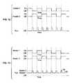
- FIG. 12is a diagrammatic representation of a mode of operation for heaters and a fan of any of the volatile material diffusers of FIGS. 1 , 4 , 6 , and 8 ;
- FIG. 13is a diagrammatic representation of a mode of operation for heaters and a fan of any of the volatile material diffusers of FIGS. 1 , 4 , 6 , and 8 ;
- FIG. 14is a diagrammatic representation of another embodiment of a volatile material diffuser
- FIGS. 15 and 16are diagrammatic representations of different modes of operation for heaters and fans of the volatile material diffuser of FIG. 11 ;
- FIGS. 17 and 18are diagrammatic representations similar to that of FIG. 1 of a further embodiment of a volatile material diffuser
- FIGS. 19-21are diagrammatic representations of further embodiments of volatile material diffusers
- FIGS. 22-24are graphical representations depicting temperature versus time for the diffusers of FIGS. 19-21 , respectively;
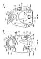
- FIG. 25is a front isometric view of a further embodiment of a volatile material diffuser
- FIGS. 26 and 27are rear and front elevational views, respectively, of the diffuser of FIG. 25 ;
- FIG. 28is an exploded view of the diffuser of FIG. 25 ;
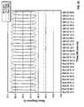
- FIG. 29is a graphical representation depicting temperature versus time for the diffuser of FIGS. 25-28 with a fan thereof turned off;
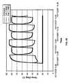
- FIG. 30is a graphical representation depicting temperature versus time for the diffuser of FIGS. 25-28 with a fan thereof turned on.
- a volatile material diffuser 30generally includes a housing 32.
- Two containers 34a, 34b having volatile materials 35a, 35b therein and wicks 36a, 36b in contact with the volatile materials 35a, 35b and extending out of the containers 34a, 34bare adapted to be inserted within the housing 32.
- the containers 34a, 34bmay be inserted into and retained within the housing 32 by any means known in the art.
- the containers 34a, 34bmay include projections (not shown) on one or more surfaces thereof that fit into and are retained by grooves, ledges, or apertures in the housing 32.
- Such arrangementsare described in detail in Wefler U.S. Design Patent No. 393,063 , Pedrotti et al. U.S. Patent No. 6,862,403 , and Duston et al. U.S. Patent No. 7,032,831 .
- the volatile materials 35a, 35b within the containers 34a, 34bmay be the same or different volatile materials 35a, 35b and also may of the same type or different types.
- the different types of volatile materials 35a, 35b that may be usedinclude, for example, an insecticide, an insect repellant, an insect attractant, a disinfectant, a mold or mildew inhibitor, a fragrance, a disinfectant, an air purifier, an aromatherapy scent, an antiseptic, an odor eliminator, a positive fragrancing volatile material, an air-freshener, a deodorizer, or the like, and combinations thereof.
- Two volatile materials 35a, 35b of the same typeneed not be utilized.
- an insecticide and a fragrancemay be used
- a disinfectant and a repellentmay be used, or any other combination of types of volatile materials 35a, 35b may be used.
- the volatile material diffuser 30a first chamber 37 including heaters 38a, 38b disposed adjacent the wicks 36a, 36b for vaporization of the volatile materials 35a, 35b, which move by capillary action through the wicks 36a, 36b to top portions 40a, 40b of the wicks 36a, 36b.
- the wicks 36a, 36b and heaters 38a, 38breside within channels 41a, 41b (only 41b shown) formed within the first chamber 37.
- the channels 41a, 41bhave a diameter that is greater than a diameter of the wicks 36a, 36b to provide a gap 42a, 42b (only 42b shown) between the wicks 36a, 36b and cylindrical walls 43a, 43b (only 43b shown) forming the respective channels 41a, 41b.
- a fan 50is disposed within a second chamber 51 in a rear portion 52 of the housing 32 and slots or vents 54 are disposed opposite the fan 50 in a front wall 55 forming the chamber 51.
- the fan 50is disposed slightly above the wicks 36a, 36b and the heaters 38a, 38b along a vertical axis 56 of the diffuser 30. Referring to FIGS.
- a longitudinal axis 57a of the fan 50is coincident with a longitudinal axis 57b of the diffuser 30 and perpendicular to axes 58a, 58b of the wicks 36a, 36b, wherein the axes 58a, 58b of the wicks 36a, 36b are parallel to the vertical axis 56 of the diffuser 30.
- Air from the fan 50is directed toward the vents 54 such that the air moves vaporized volatile material(s) 35a, 35b that are emitted from the wicks 36a, 36b away from the diffuser 30.
- the fan 50also cools the wicks 36a, 36b and heaters 38a, 38b, as discussed in greater detail hereinafter.
- the diffuser 30preferably, although not necessarily, has two electrical blades 60 (only one shown) extending from a rear side 62 thereof for insertion into a common electrical socket. In this manner, the diffuser 30 is supplied direct current to operate the heaters 38a, 38b and the fan 50. Optionally, the diffuser 30 may be battery-operated.
- the diffuser 30 of FIGS. 1 and 2operates in a manner that prevents habituation to a particular volatile material 35a, 35b, if a fragrance or the like is used.
- the diffuser 30also limits the amount of mixing of two volatile materials 35a, 35b.
- the volatile materials 35a, 35bare emitted in an alternating sequence.
- a first of the heaters 38ais activated to emit a first of the volatile materials 35a.
- the first heater 38ais deactivated and a second of the heaters 38b is activated for a second period of time to emit a second of the volatile materials 35b.
- the second heater 38bis deactivated, the first heater 38a is activated, and the sequence repeats until the diffuser 30 is unplugged from the electrical socket.
- the first and second heaters 38a, 38bare activated and deactivated simultaneously.
- a third period of timemay elapse between deactivation of one of the heaters 38a, 38b and activation of the next heater 38a, 38b, thereby having no heater activated for the third period of time.
- a fourth period of timemay elapse between the activation of one of the heaters 38a, 38b and the deactivation of the other heater 38a, 38b, thereby creating an overlap of volatile materials 35a, 35b for the fourth period of time.
- the first and second periods of timemay be the same such that each heater 38a, 38b is activated for an equivalent period of time. Alternatively, the first and second periods of time may be different. The first and second periods of time may be between about 10 seconds and about 3 hours, more preferably between about 15 minutes and about 2 hours, and most preferably about 50 minutes or about 90 minutes.
- the volatile material 35a, 35b associated with the deactivated heater 38a, 38bis still vaporized due to temperatures of the wicks 36a, 36b and the heaters 38a, 38b being quite a bit above ambient temperature and taking a long period of time to return to a steady state temperature.
- the steady state temperaturemay be enough above ambient that the presence of the volatile material 35a, 35b associated with a deactivated heater 38a, 38b may still be detected throughout the period when the heater 38a, 38b is deactivated.
- This overlap in emission of two volatile materials 35a, 35bis oftentimes undesirable because users may prefer to detect a single volatile material 35a, 35b and/or the volatile materials 35a, 35b are not compatible.
- the fan 50 disposed within the diffuser 30 of the present disclosureprovides a method of minimizing the overlap in emission of volatile materials 35a, 35b.
- air flow from the fan 50flows through the vents 54 and over the channels 41 a, 41b, thereby causing a chimney effect and allowing air to flow downwardly through the gaps 42a, 42b formed by the channels 41a, 41b.
- Air flow through the channels 41a, 41bcools the wicks 36a, 36b and heaters 38a, 38b.
- a testing protocolwas established and followed to demonstrate the effectiveness of the fan 50 in minimizing overlap of emission of volatile materials 35a, 35b. The testing protocol was conducted on a multi-fragrancing diffuser similar to the diffuser 30 depicted in FIG.
- First and second thermocoupleswere inserted into central portions of the first and second wicks 36a, 36b, respectively, coincident with axes 58a, 58b of the wicks 36a, 36b to measure a temperature of each of the wicks 38a, 38b during various points in time during the testing protocol.
- the testing protocolfirst included a baseline test to show temperatures of the first and second wicks 36a, 36b with the fan turned off. The result was that, except for a jump in temperature from about time 13:45:00 to about time 14:00:00, each of the wicks 36a, 36b reached a maximum temperature of about 57 or 58 degrees Celsius (between about 135 or 136 degrees Fahrenheit) and each of the wicks 36a, 36b reached a minimum temperature of about 30 degrees Celsius (about 86 degrees Fahrenheit) with ambient temperature being about 21 degrees Celsius (about 70 degrees Fahrenheit).
- the fan 50is angled upwardly at an angle of about 45 degrees with respect to the longitudinal axis 57b of the diffuser 30.
- the fan 50is further directed toward a center point between axes 58a, 58b of the wicks 36a, 36b such that an equal amount of airflow is directed toward each wick 36a, 36b.
- the wicks 36a, 36breached a maximum temperature of between about 43 and about 45 degrees Celsius (between about 109 and 113 degrees Fahrenheit) and each of the wicks 36a, 36b reached a minimum temperature of about 25 degrees Celsius (about 77 degrees Fahrenheit) with ambient temperature still being about 21 degrees Celsius (about 70 degrees Fahrenheit).
- both the minimum and maximum temperatures of the wicks 36a, 36bare less than the minimum and maximum temperatures of the wicks 36a, 36b with no fan 50, as seen in FIG. 3 .
- the associated wick 36a, 36bDuring deactivation of a heater 38a, 38b, the associated wick 36a, 36b generally cooled enough that the associated volatile material 35a, 35b would not be perceived by most users.
- the fan 50is angled upwardly at an angle of about 22.5 degrees with respect to the longitudinal axis 57b of the diffuser 30.
- the wicks 36a, 36breached a maximum temperature of between about 38 and about 48 degrees Celsius (between about 100 and about 118 degrees Fahrenheit) and each of the wicks 36a, 36b reached a minimum temperature of between about 24 and about 26 degrees Celsius (between about 75 and about 79 degrees Fahrenheit) with ambient again being about 21 degrees Celsius (about 70 degrees Fahrenheit).
- the fan 50cools the wicks 36a, 36b and/or heaters 38a, 38b when the heaters 38a, 38b are activated and deactivated.
- the keyis to find an angle at which the wick 36a, 36b associated with the activated heater 38a, 38b is not cooled too much as to decrease a user's enjoyment of the diffuser 30, but where the angle is such that the wick 36a, 36b associated with the deactivated heater 38a, 38b is cooled enough such that most users generally cannot perceive the volatile material 35a, 35b associated with the deactivated heater 38a, 38b.
- FIGS. 1 and 8Other fan 50 orientations are depicted in FIGS. 1 and 8 .
- the fan 50is not angled upwardly or downwardly at all (at zero degrees) with respect to the longitudinal axis 57b of the diffuser 30.
- FIG. 8depicts the fan 50 angled downwardly about 5 degrees with respect to the longitudinal axis 57b of the diffuser 30.
- vents 54Although a set number of vents 54 is depicted in the embodiments herein, any number of vents 54 may be utilized in any of the embodiments herein.
- the fans 50 hereinare shown angled upwardly at 45 degrees with respect to the longitudinal axis 57b of the diffuser 30, upwardly at 22.5 degrees with respect to the longitudinal axis 57b, at zero degrees with respect to the longitudinal axis 57b, and downwardly at 5 degrees with respect to the longitudinal axis 57b, other angles are possible. Specifically, any angle disposed between a downward angle of about 45 degrees and an upward angle of about 45 degrees with respect to the longitudinal axis 57b of the diffuser 30 is possible.
- the fan 50 of any of the embodiments hereinmay be angled toward a side wall 64a, 64b of the housing 32 with respect to a longitudinal axis 57b of the diffuser 30, as seen in FIG. 9 , if it is desired to cool one of the wicks 36a, 36b more than the other.
- the fan 50may be angled toward either side wall 64a, 64b at an angle of between about 0 and about 45 degrees with respect to the longitudinal axis 57b.
- the fan 50was not angled upwardly or downwardly (at zero degrees) with respect to the longitudinal axis 57b ( FIG. 1 ) and was angled toward the second wick 36b, as seen in FIG. 9 .
- the second wick 36bis cooled much more than the first wick 36a.
- the second wick 36bhas a maximum temperature of about 28 degrees Celsius (about 82 degrees Fahrenheit) and a minimum temperature of about 23 degrees Celsius (about 73 degrees Fahrenheit), with ambient temperature being about 21 degrees Celsius (about 70 degrees Fahrenheit).
- the first wick 36ahas a maximum temperature of about 47 degrees Celsius (about 117 degrees Fahrenheit) and a minimum temperature of about 27 degrees Celsius (about 81 degrees Fahrenheit).
- a diffuser 30was utilized wherein the fan 50 was angled downwardly at angle of 5 degrees with respect to the longitudinal axis 57b of the diffuser 30 ( FIG. 8 ) and angled toward the second wick 36b, as seen in FIG. 9 .
- the resultwas a maximum temperature for the first wick 36a of about 45 degrees Celsius (about 113 degrees Fahrenheit) and minimum temperature of about 27 degrees Celsius (about 81 degrees Fahrenheit).
- the second wick 36bhad a maximum temperature of about 26 degrees Celsius (about 79 degrees Fahrenheit) and a minimum temperature of about 22 degrees Celsius (about 72 degrees Fahrenheit), with ambient again at about 21 degrees Celsius (about 70 degrees Fahrenheit).
- the fan 50is shown angled toward the second wick 36b with respect to the longitudinal axis 57b in FIG. 9 , the fan 50 could also be angled toward the first wick 36a.
- the goal in the embodiments of FIGS. 9-11is to cool one wick 36a, 36b at a much faster rate than the other wick 36a, 36b and/or to provide much less heat overall to one wick 36a, 36b than the other wick 36a, 36b. This may be desired when two different types of volatile materials 35a, 35b are utilized or there is simply a desire to emit one volatile material 35a, 35b less than another.
- the fan 50may be operated such that energy is continuously supplied to the fan 50, thus the fan 50 supplies a continuous air flow.
- the fan 50may also be operated at a single speed, wherein the speed is not altered during the sequence, as described above.
- energymay be supplied intermittently to the fan 50 to create intermittent flows of air.
- FIG. 12depicts first and second heaters 38a, 38b that are activated and deactivated at the same time throughout the alternating sequence.
- Energyis supplied to the fan 50 for a fifth period of time after the deactivation of each heater 38a, 38b, as further depicted in FIG. 12 .
- the fifth period of timeis between about 30 seconds and about 5 minutes depending on a speed of air flow from the fan 50, an angle of the fan 50, and a temperature of the surrounding air.
- the heaters 38a, 38bare energized in the same fashion as in FIG. 12 , but the fan 50 is continuously energized.
- a speed of the fan 50is alternated between a first speed 80 and a second speed 82.
- the fan 50is energized to run at the second speed 82 immediately after deactivation of a heater 38a, 38b for the fifth time period and the rest of the time, the fan 50 is energized to run at the first speed 80.
- the first and second speeds 80, 82are different from one another, the second speed 82 is preferably greater than the first speed 80, and both speeds are greater than zero rotations per minute in this embodiment.
- the second speed 82 being greater than the first speed 80not only provides cooling for the wicks 36a, 36b immediately after deactivation of a corresponding heater 38a, 38b, but also simultaneously provides a burst of the volatile material 35a, 35b corresponding to the activated heater 38a, 38b.
- the first speed 80 being less than the second speed 82also modulates the amount of volatile material 35a, 35b that is emitted such that bursts of the volatile materials 35a, 35b aid in minimizing habituation.
- each of the fans 100a, 100bis aligned with a single wick 36a, 36b and a single heater 38a, 38b, respectively.
- the heaters 38a, 38bmay be energized in any fashion as described herein.
- the heaters 38a, 38bare alternated similarly to the manner in which the heaters 38a, 38b are alternated in FIGS. 12 and 13 .
- the fans 100a, 100bare also automatically alternated such that the fan 100a, 100b associated with a heater 38a, 38b is activated when the associated heater 38a, 38b is deactivated.
- the fans 100a, 100bare shown as being activated for the entire period that the associated heater 38a, 38b is deactivated, whereas in FIG. 16 , the fans 100a, 100b are only activated for the fifth period of time when the associated heater is deactivated.
- FIGS. 12, 13 , 15, and 16 depicting activation and deactivation of the heaters 38a, 38b and fans 50 or 100a, 100bare meant to show examples of activation and deactivation of same and are not meant to be limiting.
- the heaters 38a, 38bmay be alternated in any fashion, as described in detail above.
- a shield 110 in the form of a wall or other blocking structureis disposed external to the second chamber 51 between the first and second fans 100a, 100b so as to block air flow from the first fan 100a to the second wick 36b and the second heater 38b and block air flow from the second fan 100b to the first wick 36a and the first heater 38a.
- a set of louvers 120may replace the vents 54, as discussed herein.
- the louvers 120are shown in FIG. 17 as parallel to the axis 57a of the fan 50.
- An adjustment mechanism 122may be placed on the housing 32 to allow a user to adjust the louvers 120.
- the louvers 120may be moved to any angle between a downward angle of about 45 degrees with respect to the longitudinal axis 57b of the diffuser 30 and an upward angle of about 45 degrees with respect to the longitudinal axis 57b.
- FIG. 18depicts the louvers 120 in an adjusted position having a downward angle of about 30 degrees.
- louvers 120are shown in FIG. 17 as directing air flow, any means by which air flow can be directed may be utilized.
- FIGS. 19-21Another independent set of tests was conducted on the volatile material diffusers 30 depicted in FIGS. 19-21 , wherein such diffusers 30 are similar to the diffusers 30 of FIGS. 2 , 4 , 6 , and 8 , except in the angling of the fan 50.
- the same testing protocol as described abovewas utilized.
- the fan 50is angled at 36 degrees, 21 degrees, and -9 degrees with respect to the longitudinal axis 57b of the diffuser 30, respectively.
- Each diffuser 30 of FIGS. 19-21was tested for a period of time and the results were recorded in FIGS. 22-24 , respectively. Referring to FIG.
- FIG. 23represents test results from the diffuser 30 of FIG. 20 , wherein the fan 50 is angled at about 21 degrees with respect to the longitudinal axis 57b.
- the wicks 36a, 36breached a maximum temperature of between about 53 and about 61 degrees Celsius (between about 127 and about 142 degrees Fahrenheit) and the wicks 36a, 36b reached a minimum temperature of between about 28 and about 32 degrees Celsius (between about 82 and about 90 degrees Fahrenheit).
- FIGS. 25-28A further embodiment of a volatile material diffuser 130 is depicted in FIGS. 25-28.
- the diffuser 130is similar to and works in the same manner as any of the diffusers 30 herein.
- the diffuser 130includes a housing 132 for holding two containers 134a, 134b having volatile materials 135a, 135b therein and wicks 136a, 136b extending therefrom.
- the housing 132includes a rear portion 138, a cover portion 140, and a mounting structure 142.
- the mounting structure 142is attached to the rear portion 138 and the cover portion 140 is mounted to the rear portion 138 and the mounting structure 142 such that the mounting structure 142 is disposed between the rear and cover portions 138, 140.
- the mounting structure 142includes front and rear portions 144a, 144b, wherein the front portion 144a includes a horizontal surface 146 having first channels 150a, 150b extending therethrough, ring heaters 152a, 152b disposed atop structures forming the first channels 150a, 150b, and second channels 154a, 154b positioned over the ring heaters 152a, 152b.
- the heaters 152a, 152bare disposed above the first channels 150a, 150b, and the second channels 154a, 154b are disposed above the heaters 152a, 152b.
- Ring channels 156a, 156b formed through the ring heaters 152a, 152b, the first channels 150a, 150b, and the second channels 154a, 154bare all aligned along vertical axes 158a, 158b.
- a fan supporting structure 170 having a fan 171 thereinextends upwardly from the rear portion 144b of the mounting structure 142 above the second channels 154a, 154b and a semi-circular structure 172 is disposed between the second channels 154a, 154b below the fan 170.
- the semi-circular structure 172prevents air flow from the fan 170 from circulating throughout the diffuser 130.
- a printed circuit board (PCB) 180is secured within the rear portion 144b of the mounting structure 142 and includes all circuitry to control the diffuser 130.
- First and second light emitting diodes (LEDs) 182a, 182bextend from an upper edge 184 of the PCB 180 and are disposed adjacent rear surfaces 186a, 186b of the second channels 154a, 154b. When the LED's 182a, 182b are illuminated, the light can be seen through the rear surfaces 186a, 186b, respectively.
- the LEDs 182a, 182bmay be illuminated when respective heaters 152a, 152b are actuated.
- a light source 187may be disposed at any location within the diffuser 130.
- the light source 187may include first and second colored LEDs 189a, 189b disposed with a single lens 191 in the form of a diffuser, as seen in FIGS. 25 and 27 .
- the LEDsmay be of any color, but in a specific example, a first of the LEDs 189a is red and a second of the LEDs 189b is blue.
- the first LED 189ais illuminated to project a red color
- the second LED 189bis illuminated to project a blue color
- neither of the heaters 152a, 152bis activated
- neither of the LEDs 189a, 189bis illuminated
- both of the LEDs 189a, 189bare illuminated to create a blended purple color.
- This featureprovides a visual color indication to a user of what volatile materials are being emitted and an indication of when changes in volatile materials have occurred.
- a single LED that emits multiple colorscan be utilized to provide the same feature.
- light sources 200a, 200bmay be disposed behind the containers 134a, 134b, such that light from the light sources 200a, 200b shines through the containers 134a, 134b and the volatile materials 135a, 135b therein when illuminated.
- the light sources 200a, 200binclude a single LED 201a, 201b.
- the LEDs 201a, 201bmay project colored or white light and/or each LED 201a, 201b may project the same or different colored light.
- the light sources 200a, 200bmay include any number of LEDs, any of which may be colored.
- each light source 200a, 200bincludes multiple different colored LEDs that are illuminated to produce a light show.
- an associated light source 200a, 200bis activated to indicate to the user which volatile material 135a, 135b is being emitted.
- a light source 203may be disposed on a lower surface of the horizontal surface 146. In such case, the light source 203 would shine downwardly onto the containers 134a, 134b.
- the light source 203includes either multiple LEDs or a multi-colored LED. As the volatile material being automatically changed, a color emitted by the light source 203 may also change.
- the heaters 152a, 152bare activated and deactivated at the same time and the light source 203 includes a tri-colored LED, while the first heater 152a is activated to emit the first volatile material 135a, a red color may be emitted from the light source 203.
- the red coloris replaced with a blue color or morphs into the blue color.
- This change in color of the light source 203indicates to the user that a new volatile material is being emitted, but not necessarily which volatile material is being emitted.
- an intensity level switch 188extends from the PCB 180 and includes an actuator arm 190 that extends through an aperture 192 in the rear portion 138 of the housing 132.
- a button 194is disposed over the actuator arm 190 to change a position of the switch 188.
- the position of the switch 188is sensed by the PCB 180 and an intensity level at which the volatile materials 135a, 135b are emitted is varied based on the position of the switch 188.
- an intensity of the LEDs and/or light sources 182a, 182b, 189a, 189b, 201a, 201b, and/or 203may be varied.
- the LEDs and/or light sources 182a, 182b, 189a, 189b, 201a, 201b, and/or 203 associated with the activated heaters 152a, 152bare illuminated at their highest intensity level
- the LEDS and/or light sources 182a, 182b, 189a, 189b, 201a, 201b, and/or 203 associated with the activated heaters 152a, 152bare illuminated at their lowest intensity level
- the LEDs and/or light sources 182, 182b, 189a, 189b, 201a, 201 b, and/or 203 associated with the activated heaters 152a, 152bare illuminated at respective intensity levels.
- two intensity level switches 188may be utilized, wherein each switch 188 controls the intensity level of a particular volatile material 135a, 135b
- a volatile material selector switch(not shown) or another type of switch may be utilized.
- the volatile material selector switchwould allow a user to select to emit a first of the volatile materials 135a, a second of the volatile materials 135b, or both of the volatile materials 135a, 135b in an alternating sequence.
- the diffuser 130 or any of the diffusers hereinmay include an odor sensor that senses an amount of volatile material in the diffuser 130. If the sensor no longer detects volatile materials, meaning that containers 136a, 136b are empty or have little volatile material 135a, 135b therein, the sensor can notify the PCB 180.
- the PCB 180indicates to the user that one or more of the containers 136a, 136b need to be replaced, such as by deactivating the LEDs 182a, 182b and/or 189a, 189b, deactivating the heaters 152a, 152b, and/or illuminating one or more LEDs 182a, 182b and/or 189a, 189b in a different color, such as yellow or black.
- the diffuser 130 or any of the diffusers hereinmay include a membrane 202a, 202b as seen in FIG. 25 within the container 134a, 134b, preferably along at least a portion of an inner surface of the container 134a, 134b.
- the membranes 202a, 202bWhen volatile materials 135a, 135b are disposed within the containers 134a, 134b, the membranes 202a, 202b are wet and transparent. As the volatile materials 135a, 135b are dispensed from the containers 134a, 134b, the membranes 202a, 202b begin to dry out and become opaque. The opaque nature of the membrane 202a, 202b indicates to the user that the container 134a, 134b needs to be replaced. If LEDs 201a, 201b ( FIG.
- a plug assembly 210is connected to the rear portion 144b of the mounting structure 142 and extends through an aperture 212 in the rear portion 138 of the housing 132. Electrical blades 214a, 214b of the plug assembly 210 are inserted into an electrical socket to power the diffuser 130.
- the rear portion 138 of the housing 132includes a plurality of inflow vents 220 and the cover portion 140 includes a plurality of outflow vents 222.
- the vents 220, 222are shown in a particular semi-circular configuration, any suitable configuration is possible.
- the fan 170is disposed between the inflow and outflow vents 220, 222 such that, when the fan 170 is running, air is pulled in through the inflow vents 220 and air is pushed out the outflow vents 222 to circulate the volatile materials 135a, 135b, as they are emitted.
- the containers 134a, 134b, as seen in FIG. 25are inserted into the diffuser 130 by inserting portions of the wicks 136a, 136b that extend out of the respective containers 134a, 134b through the first channels 150a, 150b and the ring channels 156a, 156b, respectively, such that the wicks 136a, 136b reside in same and gaps are formed between the wicks 136a, 136b and walls forming the first channels 150a, 150b and the ring channels 156a, 156b.
- the fan 170When the fan 170 is activated, airflow therefrom flows over the second channels 154a, 154b, causing a chimney effect and allowing air to flow downwardly through the second channels 154a, 154b and through the gaps formed between the wicks 136a, 136b and the first channels 150a, 150b and the ring channels 156a, 156b, thereby cooling the wicks 136a, 136b and/or heaters 152a, 152b.
- the containers 134a, 134bare retained within the diffuser 130 by opposing shell-shaped apertures 240a, 240b and shell-shaped grooves 242a, 242b.
- shell-shaped protrusions 244a, 244b on opposing sides of the containers 134a, 134bslide into opposing apertures 240a, 240b and grooves 242a, 242b, wherein the containers 134a, 134b must be pulled downwardly to overcome an interference formed by walls forming the apertures 240a, 240b and grooves 242a, 242b.
- the diffuser 130 of FIGS. 25-28was tested with the fan 170 on and with the fan 170 off.
- the test results of FIGS. 29 and 30were generated by using the same methodology as described above.
- the graph of FIG. 29depicts temperature versus time for the diffuser 130 with the fan 170 turned off.
- the maximum temperatures for each of the wicks 136a, 136bare between about 80 degrees Celsius and about 85 degrees Celsius (between about 176 and about 185 degrees Fahrenheit) and the minimum temperatures for each of the wicks during the testing period are between about 36 degrees Celsius and about 39 degrees Celsius (between about 97 and about 102 degrees Fahrenheit).
- the maximum temperatures for the wicks 136a, 136bis between about 63 and about 67 degrees Celsius (between about 145 and about 153 degrees Fahrenheit) and the minimum temperatures for the wicks 136a, 136b during the same period is between about 29 and about 31 degrees Celsius (between about 84 and about 88 degrees Fahrenheit).
- ambient temperaturewas about 20 degrees Celsius (about 68 degrees Fahrenheit).
- the fan 170provides cooling for the wicks 136a, 136b and/or heaters 152a, 152b, such that the amount of volatile material associated with a deactivated heater 152a, 152b that is emitted is minimized, preferably to a point that such volatile material is not sensed by a user.
- any means for providing a flow of aircould be utilized including, but not limited to, an axial propeller-type fan, a centrifugal-type squirrel cage blower, a peristaltic pump, or any other fans or pumps known in the art.
- the present applicationprovides a volatile material diffuser for emitting more than one volatile material therefrom, wherein the volatile materials are emitted in an alternating sequence.
- the volatile materialsare vaporized by heaters and a fan aids in exhausting the vaporized materials from the diffuser.
- An air flow from the fanalso cools the heaters and associated wicks containing the volatile materials after they have been deactivated such that the amount of the overlap of volatile materials is minimized.
- One or more LEDsmay be incorporated into a diffuser to indicate which volatile material(s) is being emitted, to provide a visual effect, to indicate that the volatile material being emitted has changed, and/or to aid in indicating to a user that a container containing a volatile material needs to be replaced.
Landscapes
- Life Sciences & Earth Sciences (AREA)
- Health & Medical Sciences (AREA)
- Pest Control & Pesticides (AREA)
- General Health & Medical Sciences (AREA)
- Epidemiology (AREA)
- Veterinary Medicine (AREA)
- Public Health (AREA)
- Animal Behavior & Ethology (AREA)
- Toxicology (AREA)
- Environmental Sciences (AREA)
- Zoology (AREA)
- Wood Science & Technology (AREA)
- Insects & Arthropods (AREA)
- Engineering & Computer Science (AREA)
- Catching Or Destruction (AREA)
- Disinfection, Sterilisation Or Deodorisation Of Air (AREA)
Description
- The present invention relates to volatile material diffusers, and more particularly, volatile material diffusers for dispensing volatile materials from more than one container. 2. Description of the Background
- A multitude of volatile material diffusion devices or diffusers exist in the marketplace. Many of such devices are passive devices that require only ambient air flow to disperse the liquid active material therein. Other devices are battery-powered or receive household power via a plug extending from the device. A cord may be coupled between the plug and the device, or the plug may be mounted directly on the device.
- Various means for dispensing volatile materials from volatile material diffusers are also known in the art. For example, some diffusers include a heating element for heating a volatile material to promote vaporization thereof. Other diffusers employ a fan or blower to generate air flow to direct volatile material out of the diffuser into the surrounding environment. In another type of diffuser, one or more volatile materials may be emitted from the diffuser using a bolus generator that delivers a pulse of air to eject a scent ring. Still other diffusers that dispense volatile materials utilize ultrasonic means to dispense the volatile materials therefrom. In addition, other diffusers utilize more than one of these means to vaporize and/or disperse volatile materials.
- In the past, such means have been utilized to dispense one or more volatile materials from a single diffuser. Multiple volatile materials have been used to prevent habituation, which is a phenomenon that occurs when a person becomes used to a particular volatile material such that they no longer perceive that volatile material.
- One such device for emitting multiple volatile materials includes a multi-aroma cartridge having a frame with sections containing absorbent material saturated with different fragrances. The cartridge is inserted into a device having heaters disposed beneath each of the sections containing absorbent material. The heaters are actuated to dispense different fragrances.
- One multi-fragrancing device includes two containers each having a wick extending therefrom and in contact with fragrances with the containers. Ring heaters are disposed around each of the wicks to vaporize fragrance disposed within the respective wicks. Energy is continuously supplied to a first of the heaters to continuously supply a first of the fragrances and energy is intermittently supplied to a second of the heaters to intermittently supply a second of the fragrances. The intermittent supply of the second fragrance prevents habituation with respect to the first fragrance by periodically supplying the second fragrance.
- A further multi-fragrancing device includes first and second containers having first and second wicks respectively extending therefrom and in contact with first and second volatile materials disposed in the first and second containers, respectively. First and second heaters are disposed adjacent the first and second wicks, respectively, wherein the first and second heaters are alternately energized to alternately vaporize and disperse the first and second fragrances. In this device, the alternation of fragrances for a period of time, such as between 15 minutes and 2 hours, prevents habituation with respect to both of the fragrances.
- Another multi-fragrancing device is shown in
US 2004/0247301 and utilizes both heat and air flow to vaporize and disperse fragrances. Two containers having wicks extending therefrom and in contact with fragrances in the containers are disposed within the device. One or more heaters are disposed adjacent the wicks and one or more fans are disposed behind the wicks. A wall is disposed above the wicks to allow vaporized fragrance therethrough for dispersion by the one or more fans. The wall prevents air flow from the fan from cooling the heaters and/or wicks.
Yet another multi-fragrancing arrangement is shown inWO 2005/092400 on which the pre-characterizing part of claim is based. - In one aspect of the present invention, a volatile material diffuser is provided as defined in
claim 1 below. - In second aspect of the present invention, a method of preventing undesired mixing of volatile materials as defined in
claim 14 below. - Other aspects and advantages of the present application will become apparent upon consideration of the following detailed description and the attached drawings, in which like elements are assigned like reference numerals.
FIG. 1 is a diagrammatic representation of a first embodiment of a volatile material diffuser;FIG 2 is a cross-sectional view taken generally along the lines 2-2 ofFIG. 1 ;FIG. 3 is a graphical representation depicting temperature versus time for the diffuser ofFIG. 1 with a fan turned off;FIG. 4 is a diagrammatic representation similar to that ofFIG. 1 and illustrating a second embodiment of a volatile material diffuser;FIG. 5 is a graphical representation depicting temperature versus time for the diffuser ofFIG. 4 ;FIG. 6 is a diagrammatic representation similar to that ofFIG. 1 and depicting a third embodiment of a volatile material diffuser,FIG. 7 is a graphical representation depicting temperature versus time for the diffuser ofFIG. 6 ;FIG. 8 is a diagrammatic representation similar to that ofFIG. 1 and illustrating a further embodiment of a volatile material diffuser,FIG. 9 is a top elevational view of a further embodiment of a volatile material diffuser;FIGS. 10 and11 are graphical representations depicting temperature versus time for two variations of the diffuser ofFIG. 9 ;FIG. 12 is a diagrammatic representation of a mode of operation for heaters and a fan of any of the volatile material diffusers ofFIGS. 1 ,4 ,6 , and8 ;FIG. 13 is a diagrammatic representation of a mode of operation for heaters and a fan of any of the volatile material diffusers ofFIGS. 1 ,4 ,6 , and8 ;FIG. 14 is a diagrammatic representation of another embodiment of a volatile material diffuser;FIGS. 15 and 16 are diagrammatic representations of different modes of operation for heaters and fans of the volatile material diffuser ofFIG. 11 ;FIGS. 17 and 18 are diagrammatic representations similar to that ofFIG. 1 of a further embodiment of a volatile material diffuser;FIGS. 19-21 are diagrammatic representations of further embodiments of volatile material diffusers;FIGS. 22-24 are graphical representations depicting temperature versus time for the diffusers ofFIGS. 19-21 , respectively;FIG. 25 is a front isometric view of a further embodiment of a volatile material diffuser;FIGS. 26 and27 are rear and front elevational views, respectively, of the diffuser ofFIG. 25 ;FIG. 28 is an exploded view of the diffuser ofFIG. 25 ;FIG. 29 is a graphical representation depicting temperature versus time for the diffuser ofFIGS. 25-28 with a fan thereof turned off; andFIG. 30 is a graphical representation depicting temperature versus time for the diffuser ofFIGS. 25-28 with a fan thereof turned on.- Referring to
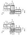
FIGS. 1 and 2 , avolatile material diffuser 30 generally includes ahousing 32. Twocontainers volatile materials wicks volatile materials containers housing 32. Thecontainers housing 32 by any means known in the art. For example, thecontainers housing 32. Such arrangements are described in detail inWefler U.S. Design Patent No. 393,063 ,Pedrotti et al. U.S. Patent No. 6,862,403 , andDuston et al. U.S. Patent No. 7,032,831 . - The
volatile materials containers volatile materials volatile materials volatile materials volatile materials - Referring again to
FIGS. 1 and 2 , the volatile material diffuser 30 afirst chamber 37 includingheaters wicks volatile materials wicks top portions wicks wicks heaters channels first chamber 37. Thechannels wicks gap wicks cylindrical walls respective channels - A
fan 50 is disposed within asecond chamber 51 in arear portion 52 of thehousing 32 and slots orvents 54 are disposed opposite thefan 50 in afront wall 55 forming thechamber 51. Thefan 50 is disposed slightly above thewicks heaters vertical axis 56 of thediffuser 30. Referring toFIGS. 1 and 2 , alongitudinal axis 57a of thefan 50 is coincident with alongitudinal axis 57b of thediffuser 30 and perpendicular toaxes wicks axes wicks vertical axis 56 of thediffuser 30. Air from thefan 50 is directed toward thevents 54 such that the air moves vaporized volatile material(s) 35a, 35b that are emitted from thewicks diffuser 30. Thefan 50 also cools thewicks heaters - Still referring to
FIGS. 1 and 2 , thediffuser 30 preferably, although not necessarily, has two electrical blades 60 (only one shown) extending from arear side 62 thereof for insertion into a common electrical socket. In this manner, thediffuser 30 is supplied direct current to operate theheaters fan 50. Optionally, thediffuser 30 may be battery-operated. - The
diffuser 30 ofFIGS. 1 and 2 operates in a manner that prevents habituation to a particularvolatile material diffuser 30 also limits the amount of mixing of twovolatile materials volatile materials diffuser 30 is plugged into an electrical socket, a first of theheaters 38a is activated to emit a first of thevolatile materials 35a. After a first period of time, thefirst heater 38a is deactivated and a second of theheaters 38b is activated for a second period of time to emit a second of thevolatile materials 35b. After the second period of time, thesecond heater 38b is deactivated, thefirst heater 38a is activated, and the sequence repeats until thediffuser 30 is unplugged from the electrical socket. In this sequence, the first andsecond heaters heaters next heater heaters other heater volatile materials - The first and second periods of time may be the same such that each
heater - When utilizing two
volatile materials diffuser 30 ofFIGS. 1 and 2 , there is oftentimes an overlap of the emission of thevolatile materials first heater 38a is deactivated before thesecond heater 38b is activated and thesecond heater 38b is deactivated before thefirst heater 38a is activated or the first andsecond heaters heater wick volatile material heater wicks heaters volatile material heater heater volatile materials volatile material volatile materials - The
fan 50 disposed within thediffuser 30 of the present disclosure provides a method of minimizing the overlap in emission ofvolatile materials fan 50 flows through thevents 54 and over thechannels gaps channels channels wicks heaters fan 50 in minimizing overlap of emission ofvolatile materials diffuser 30 depicted inFIG. 1 and having twocontainers wicks volatile materials containers containers diffuser 30, thetop portions wicks individual ring heaters fan 50 is disposed above and behind thewicks heaters FIG. 2 . During all tests, thefan 50 was cycled between about 2000 and 2200 rotations per minute. First and second thermocouples were inserted into central portions of the first andsecond wicks axes wicks wicks - Referring to
FIG. 3 , the testing protocol first included a baseline test to show temperatures of the first andsecond wicks wicks wicks heater wick heater wick heater heater wick heater diffuser 30. This is supported in the fact that the jump did not occur again as theheaters - Referring next to
FIGS. 4-9 , different positions for thefan 50 were tested to determine the most efficient positioning of thefan 50 with respect to cooling a deactivatedwick wick volatile material - As seen in
FIG. 4 , thefan 50 is angled upwardly at an angle of about 45 degrees with respect to thelongitudinal axis 57b of thediffuser 30. In the embodiments herein in which thefan 50 is angled, thefan 50 is further directed toward a center point betweenaxes wicks wick FIG. 5 , thewicks wicks FIG. 5 , both the minimum and maximum temperatures of thewicks wicks fan 50, as seen inFIG. 3 . During deactivation of aheater wick volatile material - Referring now to
FIG. 6 , thefan 50 is angled upwardly at an angle of about 22.5 degrees with respect to thelongitudinal axis 57b of thediffuser 30. During a period of testing, as seen inFIG. 7 , thewicks wicks FIG. 7 shows that thefan 50 cools thewicks heaters heaters wick heater diffuser 30, but where the angle is such that thewick heater volatile material heater Other fan 50 orientations are depicted inFIGS. 1 and8 . InFIG. 1 , discussed in detail above, thefan 50 is not angled upwardly or downwardly at all (at zero degrees) with respect to thelongitudinal axis 57b of thediffuser 30.FIG. 8 depicts thefan 50 angled downwardly about 5 degrees with respect to thelongitudinal axis 57b of thediffuser 30.- Although a set number of
vents 54 is depicted in the embodiments herein, any number ofvents 54 may be utilized in any of the embodiments herein. - Although the
fans 50 herein are shown angled upwardly at 45 degrees with respect to thelongitudinal axis 57b of thediffuser 30, upwardly at 22.5 degrees with respect to thelongitudinal axis 57b, at zero degrees with respect to thelongitudinal axis 57b, and downwardly at 5 degrees with respect to thelongitudinal axis 57b, other angles are possible. Specifically, any angle disposed between a downward angle of about 45 degrees and an upward angle of about 45 degrees with respect to thelongitudinal axis 57b of thediffuser 30 is possible. - The
fan 50 of any of the embodiments herein may be angled toward aside wall housing 32 with respect to alongitudinal axis 57b of thediffuser 30, as seen inFIG. 9 , if it is desired to cool one of thewicks fan 50 may be angled toward eitherside wall longitudinal axis 57b. Referring to the same testing protocol as described above, inFIG. 10 , thefan 50 was not angled upwardly or downwardly (at zero degrees) with respect to thelongitudinal axis 57b (FIG. 1 ) and was angled toward thesecond wick 36b, as seen inFIG. 9 . As seen inFIG. 10 , thesecond wick 36b is cooled much more than thefirst wick 36a. In fact, thesecond wick 36b has a maximum temperature of about 28 degrees Celsius (about 82 degrees Fahrenheit) and a minimum temperature of about 23 degrees Celsius (about 73 degrees Fahrenheit), with ambient temperature being about 21 degrees Celsius (about 70 degrees Fahrenheit). Thefirst wick 36a has a maximum temperature of about 47 degrees Celsius (about 117 degrees Fahrenheit) and a minimum temperature of about 27 degrees Celsius (about 81 degrees Fahrenheit). - For the results of
FIG. 11 , adiffuser 30 was utilized wherein thefan 50 was angled downwardly at angle of 5 degrees with respect to thelongitudinal axis 57b of the diffuser 30 (FIG. 8 ) and angled toward thesecond wick 36b, as seen inFIG. 9 . The result was a maximum temperature for thefirst wick 36a of about 45 degrees Celsius (about 113 degrees Fahrenheit) and minimum temperature of about 27 degrees Celsius (about 81 degrees Fahrenheit). Thesecond wick 36b had a maximum temperature of about 26 degrees Celsius (about 79 degrees Fahrenheit) and a minimum temperature of about 22 degrees Celsius (about 72 degrees Fahrenheit), with ambient again at about 21 degrees Celsius (about 70 degrees Fahrenheit). - Although the
fan 50 is shown angled toward thesecond wick 36b with respect to thelongitudinal axis 57b inFIG. 9 , thefan 50 could also be angled toward thefirst wick 36a. The goal in the embodiments ofFIGS. 9-11 is to cool onewick other wick wick other wick volatile materials volatile material - The
fan 50 may be operated such that energy is continuously supplied to thefan 50, thus thefan 50 supplies a continuous air flow. Thefan 50 may also be operated at a single speed, wherein the speed is not altered during the sequence, as described above. Alternatively, energy may be supplied intermittently to thefan 50 to create intermittent flows of air. Such a mode of operation is depicted inFIG. 12. FIG. 12 depicts first andsecond heaters fan 50 for a fifth period of time after the deactivation of eachheater FIG. 12 . The fifth period of time is between about 30 seconds and about 5 minutes depending on a speed of air flow from thefan 50, an angle of thefan 50, and a temperature of the surrounding air. - In another embodiment, as depicted in
FIG. 13 , theheaters FIG. 12 , but thefan 50 is continuously energized. In this mode of operation, a speed of thefan 50 is alternated between afirst speed 80 and asecond speed 82. Thefan 50 is energized to run at thesecond speed 82 immediately after deactivation of aheater fan 50 is energized to run at thefirst speed 80. The first andsecond speeds second speed 82 is preferably greater than thefirst speed 80, and both speeds are greater than zero rotations per minute in this embodiment. Thesecond speed 82 being greater than thefirst speed 80 not only provides cooling for thewicks corresponding heater volatile material heater first speed 80 being less than thesecond speed 82 also modulates the amount ofvolatile material volatile materials - Referring to
FIGS. 14-16 , twofans single fan 50. Referring toFIG. 14 , each of thefans single wick single heater heaters fans FIGS. 15 and 16 , theheaters heaters FIGS. 12 and 13 . Thefans fan heater heater FIG. 15 , thefans heater FIG. 16 , thefans - The sample graphical depictions of modes of operation of
FIGS. 12, 13 ,15, and 16 depicting activation and deactivation of theheaters fans heaters - Referring again to
FIG. 14 , ashield 110 in the form of a wall or other blocking structure is disposed external to thesecond chamber 51 between the first andsecond fans first fan 100a to thesecond wick 36b and thesecond heater 38b and block air flow from thesecond fan 100b to thefirst wick 36a and thefirst heater 38a. - Referring to
FIGS. 17 and 18 , a set oflouvers 120 may replace thevents 54, as discussed herein. Thelouvers 120 are shown inFIG. 17 as parallel to theaxis 57a of thefan 50. Anadjustment mechanism 122 may be placed on thehousing 32 to allow a user to adjust thelouvers 120. As such, thelouvers 120 may be moved to any angle between a downward angle of about 45 degrees with respect to thelongitudinal axis 57b of thediffuser 30 and an upward angle of about 45 degrees with respect to thelongitudinal axis 57b.FIG. 18 depicts thelouvers 120 in an adjusted position having a downward angle of about 30 degrees. Althoughlouvers 120 are shown inFIG. 17 as directing air flow, any means by which air flow can be directed may be utilized. - Another independent set of tests was conducted on the
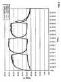
volatile material diffusers 30 depicted inFIGS. 19-21 , whereinsuch diffusers 30 are similar to thediffusers 30 ofFIGS. 2 ,4 ,6 , and8 , except in the angling of thefan 50. In addition, the same testing protocol as described above was utilized. InFIGS. 19-21 , thefan 50 is angled at 36 degrees, 21 degrees, and -9 degrees with respect to thelongitudinal axis 57b of thediffuser 30, respectively. Eachdiffuser 30 ofFIGS. 19-21 was tested for a period of time and the results were recorded inFIGS. 22-24 , respectively. Referring toFIG. 22 , which depicts testing with thefan 50 angled at about 36 degrees with respect to thelongitudinal axis 57b, thewicks wicks FIG. 23 represents test results from thediffuser 30 ofFIG. 20 , wherein thefan 50 is angled at about 21 degrees with respect to thelongitudinal axis 57b. In such test, thewicks wicks FIG. 24 , wherein a test was performed with thefan 50 angled at about -9 degrees with respect to thelongitudinal axis 57b, thewicks wicks FIGS. 19-24 , ambient temperature measured about 22 or 23 degrees with ambient about 22 degrees Celsius (about 72 or about 73 degrees Fahrenheit). As with the other test results described herein, it is evident that the angle at which thefan 50 is disposed with respect to thelongitudinal axis 57b affects the rate at which thewicks heaters - A further embodiment of a
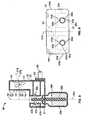
volatile material diffuser 130 is depicted inFIGS. 25-28. Thediffuser 130 is similar to and works in the same manner as any of thediffusers 30 herein. As seen inFIG. 25 , thediffuser 130 includes ahousing 132 for holding twocontainers volatile materials wicks FIG. 28 , thehousing 132 includes arear portion 138, acover portion 140, and a mountingstructure 142. The mountingstructure 142 is attached to therear portion 138 and thecover portion 140 is mounted to therear portion 138 and the mountingstructure 142 such that the mountingstructure 142 is disposed between the rear and coverportions FIG. 28 , the mountingstructure 142 includes front andrear portions front portion 144a includes ahorizontal surface 146 havingfirst channels ring heaters first channels second channels ring heaters heaters first channels second channels heaters ring heaters first channels second channels vertical axes fan supporting structure 170 having afan 171 therein extends upwardly from therear portion 144b of the mountingstructure 142 above thesecond channels semi-circular structure 172 is disposed between thesecond channels fan 170. Thesemi-circular structure 172 prevents air flow from thefan 170 from circulating throughout thediffuser 130. - As seen in
FIG. 28 , a printed circuit board (PCB) 180 is secured within therear portion 144b of the mountingstructure 142 and includes all circuitry to control thediffuser 130. First and second light emitting diodes (LEDs) 182a, 182b extend from anupper edge 184 of thePCB 180 and are disposed adjacentrear surfaces second channels rear surfaces LEDs respective heaters light source 187 may be disposed at any location within thediffuser 130. Thelight source 187 may include first and secondcolored LEDs single lens 191 in the form of a diffuser, as seen inFIGS. 25 and27 . The LEDs may be of any color, but in a specific example, a first of theLEDs 189a is red and a second of theLEDs 189b is blue. If a first of theheaters 152a is activated, thefirst LED 189a is illuminated to project a red color, if a second of theheaters 152b is activated, thesecond LED 189b is illuminated to project a blue color, if neither of theheaters LEDs heaters LEDs - In addition to or in place of the
LEDs light source 187,light sources FIG. 27 , may be disposed behind thecontainers light sources containers volatile materials light sources single LED LEDs LED light sources light source particular heater light source volatile material - Referring to
FIG. 28 , alight source 203 may be disposed on a lower surface of thehorizontal surface 146. In such case, thelight source 203 would shine downwardly onto thecontainers light source 203 includes either multiple LEDs or a multi-colored LED. As the volatile material being automatically changed, a color emitted by thelight source 203 may also change. In a non-limiting example wherein theheaters light source 203 includes a tri-colored LED, while thefirst heater 152a is activated to emit the firstvolatile material 135a, a red color may be emitted from thelight source 203. When thefirst heater 152a deactivates and thesecond heater 152b activates, the red color is replaced with a blue color or morphs into the blue color. This change in color of thelight source 203 indicates to the user that a new volatile material is being emitted, but not necessarily which volatile material is being emitted. - Still referring to
FIG. 28 , anintensity level switch 188 extends from thePCB 180 and includes anactuator arm 190 that extends through anaperture 192 in therear portion 138 of thehousing 132. Abutton 194 is disposed over theactuator arm 190 to change a position of theswitch 188. The position of theswitch 188 is sensed by thePCB 180 and an intensity level at which thevolatile materials switch 188. As the intensity level is varied, an intensity of the LEDs and/orlight sources diffuser 130 is set at a highest intensity level, the LEDs and/orlight sources heaters diffuser 130 is set at a lowest intensity level, the LEDS and/orlight sources heaters light sources heaters switch 188 controls the intensity level of a particularvolatile material particular heater - Alternatively, or in addition to the
intensity level switch 188, a volatile material selector switch (not shown) or another type of switch may be utilized. The volatile material selector switch would allow a user to select to emit a first of thevolatile materials 135a, a second of thevolatile materials 135b, or both of thevolatile materials - The
diffuser 130 or any of the diffusers herein may include an odor sensor that senses an amount of volatile material in thediffuser 130. If the sensor no longer detects volatile materials, meaning thatcontainers volatile material PCB 180. In response to a notification, thePCB 180 indicates to the user that one or more of thecontainers LEDs heaters more LEDs diffuser 130 or any of the diffusers herein may include amembrane FIG. 25 within thecontainer container volatile materials containers membranes volatile materials containers membranes membrane container LEDs FIG. 27 ) are disposed behind thecontainers LEDs containers 134a, 134 are full (and themembranes LEDs containers membranes - As seen in
FIG. 28 , aplug assembly 210 is connected to therear portion 144b of the mountingstructure 142 and extends through anaperture 212 in therear portion 138 of thehousing 132.Electrical blades plug assembly 210 are inserted into an electrical socket to power thediffuser 130. - Referring to
FIGS. 25-27 , therear portion 138 of thehousing 132 includes a plurality ofinflow vents 220 and thecover portion 140 includes a plurality of outflow vents 222. Although thevents fan 170 is disposed between the inflow andoutflow vents fan 170 is running, air is pulled in through the inflow vents 220 and air is pushed out the outflow vents 222 to circulate thevolatile materials - Referring to
FIG. 28 , thecontainers FIG. 25 are inserted into thediffuser 130 by inserting portions of thewicks respective containers first channels wicks wicks first channels fan 170 is activated, airflow therefrom flows over thesecond channels second channels wicks first channels wicks heaters FIGS. 25 ,27 , and28 , thecontainers diffuser 130 by opposing shell-shapedapertures grooves containers diffuser 130, shell-shapedprotrusions containers apertures grooves containers apertures grooves - The
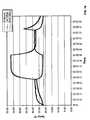
diffuser 130 ofFIGS. 25-28 was tested with thefan 170 on and with thefan 170 off. The test results ofFIGS. 29 and30 were generated by using the same methodology as described above. The graph ofFIG. 29 depicts temperature versus time for thediffuser 130 with thefan 170 turned off. As seen from the results, the maximum temperatures for each of thewicks FIG. 30 , in which thefan 170 was turned on, the maximum temperatures for thewicks wicks FIGS. 29 and30 , ambient temperature was about 20 degrees Celsius (about 68 degrees Fahrenheit). As with the test results above, thefan 170 provides cooling for thewicks heaters heater - Although a
fan - The present application provides a volatile material diffuser for emitting more than one volatile material therefrom, wherein the volatile materials are emitted in an alternating sequence. The volatile materials are vaporized by heaters and a fan aids in exhausting the vaporized materials from the diffuser. An air flow from the fan also cools the heaters and associated wicks containing the volatile materials after they have been deactivated such that the amount of the overlap of volatile materials is minimized. One or more LEDs may be incorporated into a diffuser to indicate which volatile material(s) is being emitted, to provide a visual effect, to indicate that the volatile material being emitted has changed, and/or to aid in indicating to a user that a container containing a volatile material needs to be replaced.
Claims (15)
- A volatile material diffuser (30), comprising:a housing (32);first and second containers (34a, 34b) holding first and second volatile materials (35a, 35b) and having first and second wicks (36a, 36b), respectively, in contact with respective volatile materials (35a, 35b) and extending out of respective containers (34a, 34b), wherein the containers (34a, 34b) are inserted into and detachably attached to the housing (32);first and second heaters (38a, 38b) disposed within the housing (32) adjacent the first and second wicks (36a, 36b), respectively, to vaporize the first and second volatile materials (35a, 35b), respectively;means (50) for providing an air flow disposed in the housing (32) such that air from the means (50) to provide air flow transports vaporized volatile materials (35a, 35b) away from the housing; andmeans for energizing the heaters in an alternating sequence such that when a heater (38a, 38b) is deactivated, the means (50) for providing an air flow cools a wick (36a, 36b) associated with the deactivated heater (38a, 38b);characterized in that the means for providing an air flow (50, 100a, 100b) is disposed in a first chamber (51), the wicks (36a, 36b) and heaters (38a, 38b) are disposed in a second chamber (37) separate from the first chamber, the wicks (36a, 36b) are disposed in channels (41a, 41b) formed within the second chamber (37), and the air flow moves air through gaps (42a, 42b) formed by channel walls (43a, 43b) and the wicks (36a, 36ba) to thereby cool the wicks (36a, 36b) and heaters (38a, 38b).
- The device of claim 1, wherein the means for providing an air flow is a fan (50).
- The device of claim 2, wherein the fan (50) is angled upwardly at an angle of between about 0 degrees and about 45 degrees with respect to a longitudinal axis of the diffuser (30).
- The device of claim 3, wherein the fan (50) is angled upwardly at an angle of 22.5 degrees with respect to a vertical axis of the diffuser.
- The device of claim 2, wherein the fan (50) is energized continuously and runs at one speed.
- The device of claim 2, wherein the fan is alternated between first and second different speeds and wherein the first speed is greater than the second speed such that the first speed provides a burst of the volatile material for a larger detection area and the second speed provides a more concentrated emission in a smaller detection area.
- The device of claim 2, wherein the fan (50) is energized for a period of time after the deactivation of each heater (38a, 38b) to aid in cooling the deactivated heater (38a, 38b) and the wick associated with the deactivated heater and wherein the period of time is between about 30 seconds and about 5 minutes.
- The device of claim 1 further including a second means (100b) for providing an air flow, wherein the first-named means (100a) is associated with the first heater (38a) and the second means (100b) is associated with the second heater (38b), the first-named means (100a) is energized for a period of time when the first heater (38a) is deactivated, and the second means (100b) is energized for the period of time when the second heater (38b) is deactivated, and wherein the period of time is less than a period of time that the first and second heaters are activated.
- The device of claim 1 further including a light source (187) having first and second light emitting diodes (LEDs) (189a, 189b) of first and second different colors, respectively, and disposed within a single lens (191) that forms a diffuser, wherein when the first heater (152a) is activated, a first of the LEDs (189a) is illuminated, when the second heater (152b) is activated, a second of the LEDs (189b) is illuminated, when the first and second heaters (152a, 152b) are activated, the first and second LEDs (189a, 189b) are illuminated to form a third different color, and when neither of the first and second heaters (152a, 152b) is activated, neither of the LEDs (189a, 189b) is illuminated.
- The device of claim 1 further including a first light emitting diode (LED) (201a) disposed within the housing behind the first container (134a) and a second LED (210b) disposed within the housing behind the second container (134b), wherein when the first heater (152a) is activated, the first LED (201a) is illuminated and when the second heater (152b) is activated, the second LED (201b) is illuminated.
- The device of claim 10, wherein each of the containers (134a, 134b) includes a membrane (202a, 202b) on an inner surface thereof that is wet and transparent when volatile materials are disposed within the containers and wherein, as the volatile materials are dispensed, the membranes (202a, 202b) dry out and become opaque to indicate to a user that one or more of the containers needs to be replaced.
- The device of claim 11, wherein the first and second LEDs (201a, 201b) appear as a point source when the membranes (202a, 202b) are transparent and appear as a blended source of light to the user when the membranes are opaque, thereby indicating that one or more of the containers (134a, 134b) needs to be replaced.
- The device of claim 1, further including an odor sensor that senses an amount of volatile material within one or more of the containers within the diffuser, wherein when the sensor detects that there is little or no volatile material left in one or more of the containers, the sensor can notify a printed circuit board disposed within the device to activate or deactivate a light emitting diode or turn off one or more of the heaters.
- A method of preventing undesired mixing of volatile materials, the method comprising the steps of:providing a volatile material diffuser having a housing (32) and two containers (34a, 34b) detachably attached to the housing (32) and including volatile materials (35a, 35b) and wicks (36a, 36b) in contact with the volatile materials (35a, 35b) and extending out of the containers (34a, 34b);providing heaters (38a, 38b) disposed adjacent the wicks (36a, 36b); andproviding a fan (50) spaced above the wicks (36a, 36b) and heaters (38a, 38b) for providing an air flow to cool the heaters and adjacent wicks (36a, 36b) when the heaters (38a, 38b) have been deactivated,characterized in that the fan (50, 100a, 100b) is disposed in a first chamber (51), the wicks (36a, 36b) and heaters (38a, 38b) are disposed in a second chamber (37) separate from the first chamber, the wicks (36a, 36b) are disposed in channels (41a, 41b) formed within the second chamber (37), and the air flow moves air through gaps (42a, 42b) formed by channel walls (43a, 43b) and the wicks (36a, 36ba) to thereby cool the wicks (36a, 36b) and heaters (38a, 38b).
- The method of claim 14 further including the steps of angling the fan (50) upwardly at an angle of about 22.5 degrees with respect to a vertical axis of the diffuser and intermittently activating the fan (50).
Applications Claiming Priority (3)
| Application Number | Priority Date | Filing Date | Title |
|---|---|---|---|
| US861307P | 2007-12-20 | 2007-12-20 | |
| US6757108P | 2008-02-28 | 2008-02-28 | |
| PCT/US2008/013813WO2009085170A1 (en) | 2007-12-20 | 2008-12-18 | Volatile material diffuser and method of preventing undesirable mixing of volatile materials |
Publications (2)
| Publication Number | Publication Date |
|---|---|
| EP2240209A1 EP2240209A1 (en) | 2010-10-20 |
| EP2240209B1true EP2240209B1 (en) | 2013-07-10 |
Family
ID=40386355
Family Applications (1)
| Application Number | Title | Priority Date | Filing Date |
|---|---|---|---|
| EP08868171.3ANot-in-forceEP2240209B1 (en) | 2007-12-20 | 2008-12-18 | Volatile material diffuser and method of preventing undesirable mixing of volatile materials |
Country Status (9)
| Country | Link |
|---|---|
| US (1) | US8320751B2 (en) |
| EP (1) | EP2240209B1 (en) |
| JP (1) | JP2011508621A (en) |
| CN (1) | CN101951966B (en) |
| AU (1) | AU2008343917A1 (en) |
| CA (1) | CA2709084C (en) |
| ES (1) | ES2430384T3 (en) |
| MX (1) | MX2010006866A (en) |
| WO (1) | WO2009085170A1 (en) |
Cited By (1)
| Publication number | Priority date | Publication date | Assignee | Title |
|---|---|---|---|---|
| WO2018067347A1 (en)* | 2016-10-07 | 2018-04-12 | S. C. Johnson & Son, Inc. | Volatile material dispenser |
Families Citing this family (62)
| Publication number | Priority date | Publication date | Assignee | Title |
|---|---|---|---|---|
| GB0804763D0 (en)* | 2008-03-14 | 2008-04-16 | Givauden Sa | Candle |
| US8412030B2 (en)* | 2009-08-26 | 2013-04-02 | S.C. Johnson & Son, Inc. | Method and apparatus for dispensing a fragrance |
| ES2527300T5 (en)* | 2009-09-21 | 2021-03-03 | Johnson & Son Inc S C | Method of emitting a volatile material from a diffuser |
| US9259499B2 (en)* | 2010-09-15 | 2016-02-16 | Simpletek LLC | Remotely deployable vapor delivery device |
| US8517351B2 (en) | 2011-04-28 | 2013-08-27 | S.C. Johnson & Son, Inc. | Centrifugal fan device |
| US8807538B2 (en) | 2011-04-28 | 2014-08-19 | S.C. Johnson & Son, Inc. | Centrifugal fan device |
| WO2014043639A1 (en)* | 2012-09-14 | 2014-03-20 | The Schawbel Corporation | Dispensing device with fan directed air stream |
| US9474818B1 (en) | 2012-10-22 | 2016-10-25 | Marcus J. Shotey | Air freshener |
| WO2014087173A1 (en)* | 2012-12-07 | 2014-06-12 | Ostrom Elizabeth | A fragrance disperser |
| US11541143B2 (en) | 2013-04-01 | 2023-01-03 | Earl Vaughn Sevy | Pop-out diffuser and mobile-power-base apparatus and method |
| US10507258B2 (en)* | 2013-04-01 | 2019-12-17 | Earl Vaughn Sevy | Compact, mobile, modular, integrated diffuser apparatus and method |
| US8720078B1 (en)* | 2013-08-07 | 2014-05-13 | Fawzi Q.M.A.O.A. Behbehani | Automatic hair dryer with fluid dispenser |
| US9149031B2 (en) | 2013-09-13 | 2015-10-06 | S.C. Johnson & Son, Inc. | Portable area repellent device |
| ES2543893B1 (en) | 2013-12-19 | 2016-05-31 | Zobele Espana Sa | Release system of volatile substances |
| US10220109B2 (en) | 2014-04-18 | 2019-03-05 | Todd H. Becker | Pest control system and method |
| US9474824B2 (en) | 2014-04-18 | 2016-10-25 | Thomas A. Conroy | Method and system of identifying tampering in a scent management system |
| FR3024643B1 (en) | 2014-08-07 | 2016-09-09 | Techno Bam | APPARATUS AND METHOD FOR TRAPPING FLYING INSECTS. |
| US10155059B2 (en) | 2015-03-06 | 2018-12-18 | Personal Care Products, LLC | Volatile material dispenser |
| US9821082B1 (en) | 2015-05-18 | 2017-11-21 | The Yankee Candle Company, Inc. | Connected scent device |
| US9517284B1 (en)* | 2015-07-02 | 2016-12-13 | Xenex Disinfection Services, Llc. | Germicidal apparatuses with configurations to selectively conduct different disinfection modes interior and exterior to the apparatus |
| US9867894B2 (en) | 2015-07-02 | 2018-01-16 | Xenex Disinfection Services, Llc. | Germicidal apparatuses with configurations to selectively conduct different disinfection modes interior and exterior to the apparatus |
| US10433580B2 (en) | 2016-03-03 | 2019-10-08 | Altria Client Services Llc | Methods to add menthol, botanic materials, and/or non-botanic materials to a cartridge, and/or an electronic vaping device including the cartridge |
| US10455863B2 (en) | 2016-03-03 | 2019-10-29 | Altria Client Services Llc | Cartridge for electronic vaping device |
| US10368580B2 (en)* | 2016-03-08 | 2019-08-06 | Altria Client Services Llc | Combined cartridge for electronic vaping device |
| US10357060B2 (en) | 2016-03-11 | 2019-07-23 | Altria Client Services Llc | E-vaping device cartridge holder |
| US10368581B2 (en) | 2016-03-11 | 2019-08-06 | Altria Client Services Llc | Multiple dispersion generator e-vaping device |
| RU2679418C1 (en)* | 2016-04-27 | 2019-02-08 | Конинклейке Филипс Н.В. | Air-purifying apparatus and atmosphere aromatization |
| EP3471784A1 (en)* | 2016-06-16 | 2019-04-24 | CTR, Lda | Wick device for evaporating fragrance having a flow channel |
| US10814028B2 (en) | 2016-08-03 | 2020-10-27 | Scentbridge Holdings, Llc | Method and system of a networked scent diffusion device |
| BR102016030146A2 (en)* | 2016-12-21 | 2018-07-17 | Mk Eletrodomesticos Mondial S A | basal chamber and diffuser cap for use of fan repellent refill |
| GB201718324D0 (en)* | 2017-11-06 | 2017-12-20 | Zenaura Ltd | Zenaura 1 |
| RU180368U1 (en)* | 2017-11-10 | 2018-06-08 | Антон Геннадьевич Вайс | VENTILATION INSTALLATION FOR INSTALLATION ON THE BUILDING FACADE |
| RU184488U1 (en)* | 2017-11-10 | 2018-10-29 | Антон Геннадьевич Вайс | VENTILATION INSTALLATION FOR INSTALLATION ON THE BUILDING FACADE |
| BR202017025414Y1 (en)* | 2017-11-27 | 2022-04-26 | Mk Eletrodomésticos Mondial S.A. | Constructive arrangement introduced in a fan with a volatilizing function of a repellent substance in a tablet |
| US10709805B2 (en)* | 2017-12-26 | 2020-07-14 | Matthew Aaron Alexander | Wall mountable essential oil diffuser |
| ES3037039T3 (en)* | 2018-01-18 | 2025-09-26 | Procter & Gamble | Method of delivering a volatile composition into the air |
| FR3078608B1 (en) | 2018-03-06 | 2021-07-09 | Techno Bam | APPARATUS AND METHOD FOR TRAPPING PEST FLYING INSECTS |
| CN108718469A (en)* | 2018-07-25 | 2018-10-30 | 中山赛特奥日用科技有限公司 | A kind of diffusion structure and heater of heater |
| US11980702B2 (en)* | 2019-02-27 | 2024-05-14 | Aeron Lifestyle Technology, Inc. | Scent diffusing device |
| US11246954B2 (en)* | 2019-06-14 | 2022-02-15 | The Procter & Gamble Company | Volatile composition cartridge replacement detection |
| US20210213471A1 (en)* | 2020-01-15 | 2021-07-15 | S.C. Johnson & Son, Inc. | Dispenser with a visual indication system |
| US11104451B2 (en)* | 2020-01-17 | 2021-08-31 | B/E Aerospace, Inc | Systems and methods for mitigating condensation in aircraft lighting |
| US11881093B2 (en) | 2020-08-20 | 2024-01-23 | Denso International America, Inc. | Systems and methods for identifying smoking in vehicles |
| US11760169B2 (en) | 2020-08-20 | 2023-09-19 | Denso International America, Inc. | Particulate control systems and methods for olfaction sensors |
| US11636870B2 (en) | 2020-08-20 | 2023-04-25 | Denso International America, Inc. | Smoking cessation systems and methods |
| US12251991B2 (en) | 2020-08-20 | 2025-03-18 | Denso International America, Inc. | Humidity control for olfaction sensors |
| US12017506B2 (en) | 2020-08-20 | 2024-06-25 | Denso International America, Inc. | Passenger cabin air control systems and methods |
| US11932080B2 (en) | 2020-08-20 | 2024-03-19 | Denso International America, Inc. | Diagnostic and recirculation control systems and methods |
| US12377711B2 (en) | 2020-08-20 | 2025-08-05 | Denso International America, Inc. | Vehicle feature control systems and methods based on smoking |
| US11760170B2 (en) | 2020-08-20 | 2023-09-19 | Denso International America, Inc. | Olfaction sensor preservation systems and methods |
| US11813926B2 (en) | 2020-08-20 | 2023-11-14 | Denso International America, Inc. | Binding agent and olfaction sensor |
| US12269315B2 (en) | 2020-08-20 | 2025-04-08 | Denso International America, Inc. | Systems and methods for measuring and managing odor brought into rental vehicles |
| US11828210B2 (en) | 2020-08-20 | 2023-11-28 | Denso International America, Inc. | Diagnostic systems and methods of vehicles using olfaction |
| US11938413B1 (en)* | 2020-12-13 | 2024-03-26 | Nina Minsky | Scented toy |
| EP4015071A1 (en)* | 2020-12-17 | 2022-06-22 | Zobele Holding SpA | Container for diffusing volatile substances |
| US20240226932A9 (en)* | 2021-02-26 | 2024-07-11 | Noar Brasil Indústria E Comércio De Fragrâncias Digitais Ltda | Fragrance-release device |
| US12089585B2 (en)* | 2021-07-05 | 2024-09-17 | Flextail Technology Co., Ltd | Double-sided mosquito repeller |
| JP2023047526A (en)* | 2021-09-27 | 2023-04-06 | 株式会社東海理化電機製作所 | scent generator |
| US20230226242A1 (en)* | 2022-01-19 | 2023-07-20 | Beautyavenues Llc | Plug-In Fragrance Diffuser, And Systems And Methods For Using Same |
| TWI807890B (en)* | 2022-06-29 | 2023-07-01 | 和碩聯合科技股份有限公司 | Fragrance device |
| FR3144491A1 (en) | 2023-01-04 | 2024-07-05 | Techno Bam | Apparatus, installation and method for trapping harmful insects |
| CN220916336U (en)* | 2023-06-20 | 2024-05-10 | 李文杰 | Mosquito repellent device |
Family Cites Families (318)
| Publication number | Priority date | Publication date | Assignee | Title |
|---|---|---|---|---|
| US2715056A (en) | 1955-08-09 | Wilson | ||
| US1112807A (en) | 1913-09-05 | 1914-10-06 | Alford T King | Device for distributing disinfectants or other fluids. |
| US1204934A (en) | 1915-12-02 | 1916-11-14 | William Larke Burford | Advertising medium. |
| US1829714A (en) | 1921-05-26 | 1931-10-27 | Mcelroy Shepherd & Company | Art of fire fighting and fire protection |
| US1763374A (en) | 1922-04-13 | 1930-06-10 | Annie Mertine Bernhard | Apparatus for distributing fertilizer in soluble condition |
| US1947752A (en) | 1930-02-03 | 1934-02-20 | Chain Belt Co | Fluid projector |
| US2221876A (en) | 1933-02-28 | 1940-11-19 | Thomas A Mackin | Apparatus for cleaning vehicles |
| US2094161A (en) | 1933-11-09 | 1937-09-28 | Ormond H Paddock | Cleaning device |
| US2084682A (en) | 1934-08-18 | 1937-06-22 | Guenot Maurice Pierre Joseph | Apparatus for incorporating to a stream of fluid under pressure other fluid or powdered bodies |
| US2103609A (en) | 1936-10-15 | 1937-12-28 | Harry L Divine | Car odorizer |
| US2301691A (en) | 1941-02-05 | 1942-11-10 | Ellinger | Spray washer |
| US2600877A (en) | 1948-06-09 | 1952-06-17 | Jeffree John Henry | Device for mixing fluids |
| US2555047A (en) | 1948-10-22 | 1951-05-29 | Logue Floyd | Sachet holder |
| US2608436A (en) | 1948-12-16 | 1952-08-26 | Baughman John Leonard | Air-conditioning and vaporizing fan |
| US2686944A (en) | 1950-07-07 | 1954-08-24 | Werner A Gubelin | Scent projecting apparatus |
| US2741004A (en) | 1951-01-05 | 1956-04-10 | Williams William St John | Device for diffusing the vapours of liquids |
| US2905049A (en) | 1956-06-25 | 1959-09-22 | Len Ruskin | Motion pictures with synchronized odor emission |
| US3118610A (en) | 1962-12-17 | 1964-01-21 | L & A Products Inc | Controls for pressure washers |
| US3172604A (en) | 1963-01-07 | 1965-03-09 | Brockstone Chemical Co | Timed spray unit |
| US3301486A (en) | 1963-12-05 | 1967-01-31 | Brockstone Chemical Co | Liquid dispensing apparatus |
| US3383178A (en) | 1964-12-02 | 1968-05-14 | Pittsburgh Plate Glass Co | Chemical dissolver |
| GB1120970A (en) | 1964-12-22 | 1968-07-24 | Sadakichi Sugimura | Automatic perfume atomizer |
| US3447505A (en) | 1966-02-18 | 1969-06-03 | Harry R Wagner | Apparatus for washing and waxing cars |
| US3628829A (en) | 1966-03-09 | 1971-12-21 | Morton L Heilig | Experience theater |
| US3370571A (en) | 1966-05-25 | 1968-02-27 | Univ Kentucky Res Found | Method of and apparatus for producing and dispensing an insecticide liquid |
| US3375774A (en) | 1967-01-05 | 1968-04-02 | Matsushita Electric Industrial Co Ltd | Fully automatic electric coffee pot |
| US3414864A (en) | 1967-06-08 | 1968-12-03 | Irc Inc | Electrical resistor |
| US3612356A (en) | 1969-04-01 | 1971-10-12 | James B Mcvey | Apparatus for spraying turf and the like |
| US3655135A (en) | 1970-06-29 | 1972-04-11 | Thermasol Ltd | Steam outlet head with a dispenser for a fragrance or medicant |
| US3917396A (en) | 1970-12-14 | 1975-11-04 | Xerox Corp | Control system |
| US3711023A (en) | 1971-03-26 | 1973-01-16 | D Smith | Device for controlling the evaporation of volatile substances particularly for use in air conditioning systems |
| US3763888A (en) | 1972-04-26 | 1973-10-09 | W Duecker | Aspirating valve |
| US3844057A (en) | 1972-05-02 | 1974-10-29 | F Johnson | Advertising and sales promotion method and apparatus |
| US3812996A (en) | 1972-06-08 | 1974-05-28 | Carling O Keefe Ltd | Bottle carrying case |
| US3972473A (en) | 1974-11-21 | 1976-08-03 | Sterling Drug Inc. | Spray and evaporative air freshener combination |
| US4084732A (en) | 1975-01-02 | 1978-04-18 | Dearling Harry S | Direct and indirect fragrance dispensing device |
| US4065656A (en) | 1975-06-30 | 1977-12-27 | Corning Glass Works | Electrical resistor and method of production |
| US4078891A (en) | 1976-04-02 | 1978-03-14 | Men-Sie Frischluftgerate-Vertriebe Gmbh | Air purifier |
| JPS5517443Y2 (en) | 1976-07-01 | 1980-04-23 | ||
| GB1599153A (en) | 1976-10-12 | 1981-09-30 | Strattwell Developments Ltd | Fluid dispenser |
| US4229415A (en) | 1978-06-12 | 1980-10-21 | Will Ross, Inc. | Industrial deodorizer |
| US4391390A (en) | 1981-01-21 | 1983-07-05 | Howard Arthur G | Chemical-mixing and dispensing apparatus |
| US4580721A (en) | 1981-02-12 | 1986-04-08 | Imperial Chemical Industries Plc | Fluid container |
| IL67722A0 (en) | 1982-02-05 | 1983-05-15 | Plessey Overseas | Container with memory |
| US4614300A (en) | 1982-04-19 | 1986-09-30 | E. I. Du Pont De Nemours And Company | Computerized spray machine |
| US4695434A (en) | 1982-08-27 | 1987-09-22 | Donald Spector | Aroma-generating unit |
| US4556539A (en) | 1982-08-27 | 1985-12-03 | Donald Spector | Disc-playing aroma generator |
| US4456176A (en) | 1982-09-13 | 1984-06-26 | Agius Joseph L | Apparatus for processing and dispensing fertilizer or insecticide |
| US4629604A (en) | 1983-03-21 | 1986-12-16 | Donald Spector | Multi-aroma cartridge player |
| DE3339832A1 (en) | 1983-11-01 | 1985-05-09 | Reinhard 6361 Niddatal Napierski | ELECTRICAL DEVICE FOR EVAPORATING ACTIVE SUBSTANCES, IN PARTICULAR INSECTICIDES |
| US4603030A (en) | 1984-09-20 | 1986-07-29 | Mccarthy Robert E | Scent-Emitting Systems |
| US4545396A (en) | 1985-02-25 | 1985-10-08 | Miller Richard N | System for optimum irrigating and fertilizing |
| US4680060A (en) | 1985-09-20 | 1987-07-14 | The Coca-Cola Company | Process for the extraction of contaminants from plastics |
| US4755404A (en) | 1986-05-30 | 1988-07-05 | Continental Pet Technologies, Inc. | Refillable polyester beverage bottle and preform for forming same |
| US4804821A (en) | 1986-06-24 | 1989-02-14 | Environmental Fragrance Technologies, Ltd. | Aroma diffuser assembly |
| US4731520A (en) | 1986-06-24 | 1988-03-15 | Charles Of The Ritz Group Ltd. | Aroma diffuser apparatus |
| FR2601878B1 (en) | 1986-07-24 | 1991-09-20 | Khabirova Lioutsia | OXYGENATION AND RELAXATION CABIN |
| US4730103A (en) | 1986-11-28 | 1988-03-08 | Gte Products Corporation | Compact PTC resistance heater |
| CA1318285C (en) | 1987-06-10 | 1993-05-25 | Hiroji Machida | Method for supplying aromas, apparatus therefore and facilities provided with same |
| US4798935A (en) | 1987-07-08 | 1989-01-17 | Environmental Fragrance Technologies, Ltd. | Driver circuit |
| US4795883A (en) | 1987-07-08 | 1989-01-03 | Environmental Fragrance Technologies, Ltd. | Aroma generating apparatus and driver circuit |
| USD304758S (en) | 1987-09-15 | 1989-11-21 | Environmental Fragrance Technologies, Ltd. | Fragrance cartridge |
| JPH01186423A (en) | 1988-01-20 | 1989-07-25 | Shimizu Corp | Method for supplying smell into vehicle cabin |
| JPH0718294Y2 (en) | 1988-02-10 | 1995-05-01 | アース製薬株式会社 | Heating evaporator |
| US4846403A (en) | 1988-06-24 | 1989-07-11 | Mivelaz Michael B | Watering system automatic additive dispenser |
| US4901890A (en) | 1988-06-24 | 1990-02-20 | Mivelaz Michael B | Watering system automatic additive dispenser kit |
| US4905112A (en) | 1988-06-24 | 1990-02-27 | Rhodes Steven W | Scent cassette |
| US4881568A (en) | 1988-07-06 | 1989-11-21 | Ho I Chung | Irrigation chemical dispenser |
| US4852802A (en) | 1988-08-08 | 1989-08-01 | Jerry Iggulden | Smart irrigation sprinklers |
| US4870991A (en) | 1988-08-17 | 1989-10-03 | Mcmillan Thomas A | Lawn sprinkler fertilizer device |
| US4913034A (en) | 1989-01-03 | 1990-04-03 | Ripple Joseph E J | Air handling system with deodorizer injection |
| US5022585A (en) | 1989-01-17 | 1991-06-11 | Automated Chemical Management, Inc. | Automatic chemigation |
| JPH02209147A (en) | 1989-02-07 | 1990-08-20 | Shimizu Corp | Ultrasonic scent generator |
| DE8902833U1 (en) | 1989-03-08 | 1989-07-20 | Basf Ag, 67063 Ludwigshafen | Cassette with recording medium |
| US5050798A (en) | 1989-09-13 | 1991-09-24 | Ecolab Inc. | Static air freshener device and cartridge |
| US5342584A (en) | 1989-09-13 | 1994-08-30 | Ecolab Inc. | Air freshener device and cartridge with battery |
| US5234162A (en) | 1989-09-13 | 1993-08-10 | Ecolab Inc. | Air freshener device cartridge |
| US5038972A (en) | 1989-09-26 | 1991-08-13 | Technical Concepts, Inc. | Metered aerosol fragrance dispensing mechanism |
| US5175791A (en) | 1990-05-07 | 1992-12-29 | Technical Concepts, L.P. | Fragrance diffuser having stepped power levels |
| US5111477A (en) | 1990-05-07 | 1992-05-05 | Technical Concepts, L.P. | Fragrance diffuser |
| JPH0458835A (en) | 1990-06-22 | 1992-02-25 | Trans Global:Kk | Automatically sprinkling and fertilizing apparatus |
| US5115975A (en) | 1990-07-24 | 1992-05-26 | Lynndon Shilling | Dispenser device and cartridge for volatile substance with rate control for volatilization thereof |
| USD330758S (en) | 1990-07-26 | 1992-11-03 | Technical Concepts, L.P. | Fragrance diffuser cartridge |
| US5133498A (en) | 1990-09-10 | 1992-07-28 | John Michael Sealy | Apparatus for dispensing/applying a material |
| US5105133A (en) | 1990-09-14 | 1992-04-14 | Yang Tai Her | Multiple mode perfumer |
| US5163616A (en) | 1991-01-14 | 1992-11-17 | Block Drug Company, Inc. | Air freshener device with visual signal means |
| NL9100089A (en) | 1991-01-17 | 1992-08-17 | Sara Lee De Nv | EVAPORATOR WITH COMBINED CONTINUOUS AND INSTANTACTIVE OPERATION. |
| US5152397A (en) | 1991-07-03 | 1992-10-06 | Mayled Edward C | Combination holder and container |
| US5178327A (en) | 1991-08-02 | 1993-01-12 | Summit Products, Inc. | Air freshener |
| US5186869A (en) | 1991-10-15 | 1993-02-16 | Stumpf Donald D | Electronically controlled central air freshening system and method for using same |
| EP0538527A1 (en) | 1991-10-25 | 1993-04-28 | Sano - Bruno's Enterprises Ltd. | Dual purpose electric vaporiser for tablets |
| US5227068A (en) | 1991-10-25 | 1993-07-13 | Eco-Soil Systems, Inc. | Closed apparatus system for improving irrigation and method for its use |
| DE4135796A1 (en) | 1991-10-30 | 1993-05-06 | Goetz-Ulrich London Gb Wittek | Cinema or theatre aroma distribution equipment - uses coded signals determined by performance to operate portable unit controlling mixture, duration, direction and intensity of aromas |
| US5212672A (en) | 1991-11-20 | 1993-05-18 | Loisch Julius A | Timing control apparatus |
| US5222186A (en) | 1991-12-06 | 1993-06-22 | Globol Gmbh | Electrical apparatus for vaporizing of active substances |
| US5167877A (en) | 1991-12-10 | 1992-12-01 | Pai Wen Chung | Air purifier with perfume dispensing control |
| US5192342A (en) | 1992-04-15 | 1993-03-09 | Baron Robert A | Apparatus for enhancing the environmental quality of work spaces |
| US5230837A (en) | 1992-04-30 | 1993-07-27 | Babasade Wolfgang W | Fragrance dispenser and method for fragrance dispensing |
| US5343747A (en) | 1992-06-08 | 1994-09-06 | Jay Rosen | Normalized relative humidity calibration |
| US5314669A (en) | 1992-06-15 | 1994-05-24 | Randy Hamilton | Method and apparatus for dispensing a scent into the air |
| KR960004813B1 (en) | 1992-10-06 | 1996-04-13 | 엘지전자주식회사 | TV Broadcast Transceiver |
| DE59306470D1 (en) | 1992-10-16 | 1997-06-19 | Gerold Tebbe | RECORD CARRIER AND DEVICE FOR PRODUCING TONES AND / OR IMAGES |
| DE4236886C2 (en) | 1992-10-31 | 1997-11-20 | Klocke Verpackungs Service | Containers for aromatic substances |
| US5521357A (en) | 1992-11-17 | 1996-05-28 | Heaters Engineering, Inc. | Heating device for a volatile material with resistive film formed on a substrate and overmolded body |
| US5314619A (en) | 1993-03-22 | 1994-05-24 | Eco-Soil Systems, Inc. | Method and apparatus for pond water clarification and maintenance |
| GB2279010A (en) | 1993-06-18 | 1994-12-21 | Kuan Hua Pu | A Device for selectively generating perfume gas |
| US5603513A (en) | 1993-06-28 | 1997-02-18 | Garlock, Inc. | Compressed non-asbestos gasketing for steam |
| DK0706352T3 (en) | 1993-06-29 | 2002-07-15 | Ponwell Entpr Ltd | Dispenser |
| US5434386A (en) | 1993-09-01 | 1995-07-18 | Holmes Products Corp. | Electric circuit having a heater element and a night light |
| US5321669A (en) | 1993-09-03 | 1994-06-14 | Richard Thayer | Aromatic alarm clock system |
| DE9314747U1 (en) | 1993-09-30 | 1994-02-10 | Rowenta-Werke GmbH, 63071 Offenbach | Electrical circuit arrangement for the flicker standard-compliant and network feedback-free heating power control of heating resistors of electrical household appliances, in particular electrical bread toasters |
| US5449117A (en) | 1993-10-04 | 1995-09-12 | Technical Concepts, L.P. | Apparatus and method for controllably dispensing drops of liquid |
| US5574821A (en) | 1993-11-24 | 1996-11-12 | Babasade; Wolfgang | Plug in volatile substance dispenser and method for dispensing volatiles |
| JPH07163646A (en)* | 1993-12-14 | 1995-06-27 | Casio Comput Co Ltd | Evaporator |
| US5660330A (en) | 1994-01-07 | 1997-08-26 | Scott; James F. | Automated pesticide applicator system |
| US5727186A (en) | 1994-02-01 | 1998-03-10 | The Boc Group Plc | Simulation apparatus and gas dispensing device used in conjunction therewith |
| US5377363A (en) | 1994-03-09 | 1995-01-03 | Shieh; Snoopy | Automatic lavatory detergent and perfume dispenser |
| US6141496A (en) | 1994-06-06 | 2000-10-31 | The Erie Ceramic Arts Company | Electrically heated air fresheners |
| US6234455B1 (en) | 1994-06-30 | 2001-05-22 | Gotz-Ulrich Wittek | Device and process for delivering substances for dispersal in the air |
| USD359346S (en) | 1994-07-25 | 1995-06-13 | S. C. Johnson & Son, Inc. | Dual compartment air freshener |
| USD364450S (en) | 1994-10-17 | 1995-11-21 | The Tranzonic Companies | Wall mounted deodorant dispenser |
| GB9501065D0 (en) | 1995-01-18 | 1995-03-08 | Kennedy Eng Holding David | Air freshener unit and cartridge therefor and method of dispensing air freshening vapour |
| DE69535095D1 (en) | 1995-02-23 | 2006-08-10 | Ecolab Inc | DEVICE FOR DISTRIBUTING COMFORTABLE VISCOUS SOLUTION AND ITS USE TO DISTRIBUTE |
| USD385024S (en) | 1995-03-14 | 1997-10-14 | R&C Products Pty Limited | Air freshener container |
| US5565148A (en) | 1995-03-16 | 1996-10-15 | Minnesota Mining And Manufacturing Company | Device for selectively providing a multiplicity of aromas |
| US5666987A (en) | 1995-03-24 | 1997-09-16 | Combs; Glenn A. | Chemical dispersing apparatus |
| US5772074A (en) | 1995-03-31 | 1998-06-30 | Waterbury Companies, Inc. | Device and method for indicating the dispensing of a predetermined amount of a material |
| US5524609A (en) | 1995-04-17 | 1996-06-11 | Krull; Donald L. | Scent generator for gas fireplaces |
| JPH08336576A (en)* | 1995-06-09 | 1996-12-24 | Koichi Nakayama | Perfuming device for perfume by peltier element and its combined perfurming method |
| US5680409A (en) | 1995-08-11 | 1997-10-21 | Fisher-Rosemount Systems, Inc. | Method and apparatus for detecting and identifying faulty sensors in a process |
| US5591409A (en) | 1995-08-15 | 1997-01-07 | Watkins; Carl J. | Providing aromas |
| US5725472A (en) | 1995-12-18 | 1998-03-10 | Weathers; Lawrence R. | Psychotherapy apparatus and method for the inputting and shaping new emotional physiological and cognitive response patterns in patients |
| US6017143A (en) | 1996-03-28 | 2000-01-25 | Rosemount Inc. | Device in a process system for detecting events |
| BR9601523A (en) | 1996-04-09 | 1998-03-24 | De Sousa Mauricio Araujo | Process and apparatus for programmed aromatization of environments |
| KR0159727B1 (en) | 1996-05-13 | 1999-05-01 | 김광호 | Perfume injection printing device for a printer paper |
| US5899382A (en) | 1996-05-24 | 1999-05-04 | Woodco Manufacturing, Inc. | Air freshener |
| US5724256A (en) | 1996-06-10 | 1998-03-03 | International Business Machines Corporation | Computer controlled olfactory mixer and dispenser for use in multimedia computer applications |
| US5909845A (en) | 1996-06-28 | 1999-06-08 | S. C. Johnson & Son, Inc. | Wick-based liquid emanation system with child-resistant overcap |
| US6803987B2 (en) | 1996-07-03 | 2004-10-12 | Joseph S. Manne | Portable scent delivery system |
| US5949522A (en) | 1996-07-03 | 1999-09-07 | Manne; Joseph S. | Multimedia linked scent delivery system |
| US5805768A (en) | 1996-07-08 | 1998-09-08 | Bunny Moon Enterprises | Aroma therapy diffuser |
| US5810201A (en) | 1996-07-22 | 1998-09-22 | Ecolab Inc. | Interactive dispenser for personal use chemical or personal care chemical that provides a message prompted by user proximity |
| DE19635440B4 (en) | 1996-08-31 | 2005-07-21 | Robert Bosch Gmbh | Method and device for monitoring at least one sensor |
| USD393063S (en) | 1996-10-17 | 1998-03-31 | S. C. Johnson & Son, Inc. | Volatile liquid dispenser |
| GB9622354D0 (en) | 1996-10-28 | 1997-01-08 | Culmstock Ltd | Method and apparatus incorporating air modifying agents |
| US5956663A (en) | 1996-11-07 | 1999-09-21 | Rosemount, Inc. | Signal processing technique which separates signal components in a sensor for sensor diagnostics |
| US5887118A (en) | 1997-02-12 | 1999-03-23 | Motorola, Inc. | Olfactory card |
| US5899381A (en) | 1997-02-21 | 1999-05-04 | Ceramatec, Inc. | Electrochemical device for delivery of volatile substances |
| US6123935A (en) | 1997-04-14 | 2000-09-26 | S. C. Johnson & Son, Inc. | Air freshener dispenser device with disposable heat-activated cartridge |
| US6182904B1 (en) | 1997-04-22 | 2001-02-06 | Board Of Trustees Operating Michigan State University | Automated electronically controlled microsprayer |
| ES2137111B1 (en) | 1997-06-24 | 2000-09-16 | Dbk Espana Sa | EVAPORATOR DEVICE FOR VOLATILE PRODUCTS WITH VARIABLE EVAPORATION INTENSITY. |
| ES2198542T3 (en) | 1997-07-11 | 2004-02-01 | Hts International Trading Ag | EVAPORATION LIQUID DIFFUSER. |
| JP3319990B2 (en) | 1997-08-29 | 2002-09-03 | 三菱電機株式会社 | Pressure sensor device |
| US6390453B1 (en) | 1997-10-22 | 2002-05-21 | Microfab Technologies, Inc. | Method and apparatus for delivery of fragrances and vapors to the nose |
| US6672129B1 (en) | 1997-10-22 | 2004-01-06 | Microfab Technologies, Inc. | Method for calibrating a sensor for measuring concentration of odors |
| JP2968505B2 (en) | 1998-01-14 | 1999-10-25 | 亮一 赤星 | Fragrance |
| US6039212A (en) | 1998-02-20 | 2000-03-21 | Ccl Industries Inc. | Aerosol dispenser |
| US6279836B1 (en) | 1998-03-02 | 2001-08-28 | Ecolab Inc. | Portable unit and wall unit dispensers and method of dispensing with timer |
| US6172343B1 (en) | 1998-03-09 | 2001-01-09 | Marley Electric Heating | Heater and heater control with selective power rating |
| US6000658A (en) | 1998-04-13 | 1999-12-14 | Mccall, Jr.; Tommie | Toilet paper dispenser |
| US6024783A (en) | 1998-06-09 | 2000-02-15 | International Business Machines Corporation | Aroma sensory stimulation in multimedia |
| US6041659A (en) | 1998-07-09 | 2000-03-28 | Honeywell Inc. | Methods and apparatus for sensing differential and gauge static pressure in a fluid flow line |
| US6136277A (en) | 1998-08-12 | 2000-10-24 | Nardini; Joseph | Fragrance dispersion system |
| USD437636S1 (en) | 1998-08-14 | 2001-02-13 | Dbk Espana, S.A. | Substance evaporator |
| US6713024B1 (en) | 1998-08-28 | 2004-03-30 | Aroma Technology Limited | Odor dispensing device and odor dispensing cartridge |
| RU2134052C1 (en) | 1998-10-07 | 1999-08-10 | Нерушай Сергей Алексеевич | Method and apparatus for aerosol application of perfumery liquids |
| GB2347860B (en) | 1998-10-15 | 2003-03-12 | Pankhurst Design & Development | Air freshener |
| US6053738A (en) | 1999-02-17 | 2000-04-25 | Ivey, Jr.; Ellwood G. | Sense-simile transmission machine |
| US6231032B1 (en) | 1999-02-17 | 2001-05-15 | Ellwood G. Ivey, Jr. | Sense-simile transmission machine having a rotating cylinder with cartridges for dispensing substances onto a reciprocating carrier |
| US6196218B1 (en) | 1999-02-24 | 2001-03-06 | Ponwell Enterprises Ltd | Piezo inhaler |
| PL194790B1 (en) | 1999-03-05 | 2007-07-31 | Johnson & Son Inc S C | Control system for atomizing liquids with a piezoelectric vibrator |
| AU3741100A (en) | 1999-03-12 | 2000-09-28 | Microscent, Llc. | Methods and apparatus for localized delivery of scented aerosols |
| US6361752B1 (en) | 1999-05-19 | 2002-03-26 | S. C. Johnson & Son, Inc. | Apparatus for volatilizing and dispensing a chemical into a room environment |
| FR2794039B1 (en) | 1999-05-27 | 2002-05-03 | Osmooze Sa | DEVICE FOR FORMING, MOVING AND DIFFUSING SMALL CALIBRATED QUANTITIES OF LIQUIDS |
| EP1060685A3 (en) | 1999-06-11 | 2004-01-28 | Wella Aktiengesellschaft | Method and device for conveying a specific odour to a person |
| USD449101S1 (en) | 1999-06-16 | 2001-10-09 | The Dial Corporation | Electric liquid vaporizer |
| US6104867A (en) | 1999-06-16 | 2000-08-15 | The Dial Corporation | Method and apparatus for liquid vaporization |
| FR2795348B1 (en) | 1999-06-22 | 2001-09-14 | Osmooze Sa | PROGRAMMABLE DEVICE FOR SCATTERING ODOR PICS |
| GB9916755D0 (en) | 1999-07-17 | 1999-09-15 | Reckitt & Colmann Prod Ltd | Improvements in or relating to organic compositions |
| US6569387B1 (en) | 1999-08-10 | 2003-05-27 | S.C. Johnson & Son, Inc. | Dual function dispenser |
| USD434485S (en) | 1999-08-10 | 2000-11-28 | S. C. Johnson & Son, Inc. | Dual capacity dispenser |
| WO2001030404A1 (en) | 1999-10-29 | 2001-05-03 | E. One Co., Ltd. | Scent diffusion apparatus and method thereof |
| USD466204S1 (en) | 1999-11-08 | 2002-11-26 | The Dial Corporation | Electric liquid vaporizer |
| EP1108437A1 (en) | 1999-12-17 | 2001-06-20 | Firmenich Sa | Device for the diffusion of aroma |
| DE59909132D1 (en) | 1999-12-18 | 2004-05-13 | C T R | Device for vaporizing volatile substances, especially insecticides and / or fragrances |
| US6236807B1 (en) | 2000-01-07 | 2001-05-22 | Bath & Body Works, Inc. | Wick-based liquid emanation system with child-resistant and miniaturization features |
| USD451990S1 (en) | 2000-02-11 | 2001-12-11 | Osmooze, S.A. | Aroma diffuser |
| CA2337738C (en) | 2000-02-25 | 2008-05-13 | The Dial Corporation | Variable temperature vaporizer |
| US6792199B2 (en) | 2000-02-25 | 2004-09-14 | The Dial Corporation | Variable temperature vaporizer |
| US20010048037A1 (en) | 2000-03-03 | 2001-12-06 | Bell Michael J. | Chemical infeed system for a sprinlker or irrigation system |
| WO2001065931A1 (en) | 2000-03-06 | 2001-09-13 | Fumakilla Limited | Fan type chemicals diffusing device |
| GB0005222D0 (en) | 2000-03-06 | 2000-04-26 | Reckitt & Colmann Prod Ltd | Device |
| DE10020931C1 (en) | 2000-04-28 | 2001-08-09 | Heinrich Zitzmann | Temperature sensor and method for contacting a temperature sensor |
| WO2001089590A1 (en) | 2000-05-26 | 2001-11-29 | Yukinobu Tajima | Method and apparatus for generating smell |
| US6542442B2 (en) | 2000-05-31 | 2003-04-01 | David A. Kaslon | Scent emitting device |
| US6602475B1 (en) | 2000-06-14 | 2003-08-05 | Multisen Technology, Inc. | Multimedia and scent storage medium and playback apparatus having electrostatic scent release |
| US6654664B1 (en) | 2000-06-14 | 2003-11-25 | Multisen Technology, Inc. | Multimedia and scent storage medium and playback apparatus |
| US6556272B1 (en) | 2000-06-14 | 2003-04-29 | Multisen Technology, Inc. | Multimedia and scent storage medium and playback apparatus |
| US6619559B2 (en) | 2000-07-10 | 2003-09-16 | Gregory D. Wohrle | Scent delivery system |
| US6783117B2 (en) | 2000-07-10 | 2004-08-31 | Gregory D. Wohrle | Scent delivery system |
| US20030107139A1 (en) | 2000-07-10 | 2003-06-12 | Wohrle Gregory Drew | Scent delivery system |
| AU2001280794A1 (en)* | 2000-07-27 | 2002-04-29 | The Procter & Gamble Company | Multiple scent-containing article of manufacture with theme |
| US20040033171A1 (en) | 2000-07-27 | 2004-02-19 | The Procter & Gamble Company | Systems and devices for emitting volatile compositions |
| US20020066798A1 (en) | 2000-12-04 | 2002-06-06 | Christophe Laudamiel-Pellet | Multiple scent-containing article of manufacture with theme |
| US20020068010A1 (en) | 2000-12-04 | 2002-06-06 | The Procter & Gamble Company | Articles, systems, and methods for dispensing volatile materials into the environment |
| US20040028551A1 (en) | 2000-07-27 | 2004-02-12 | Kvietok Frank Andrej | Methods for emitting volatile compositions |
| US6581915B2 (en) | 2000-07-27 | 2003-06-24 | The Procter & Gamble Company | Dispensing device for dispensing scents |
| US20040265164A1 (en) | 2000-07-27 | 2004-12-30 | The Procter & Gamble Company | Methods, devices, compositions, and systems for improved scent delivery |
| US20020068009A1 (en) | 2000-12-04 | 2002-06-06 | Christophe Laudamiel-Pellet | System and methods for dispensing scents into the environment, and for providing scent-containing articles of manufacture |
| US6931202B2 (en) | 2000-07-28 | 2005-08-16 | S.C. Johnson & Son, Inc. | Electrical evaporator with adjustable evaporation intensity |
| IT1318769B1 (en) | 2000-08-17 | 2003-09-10 | Zobele Ind Chim | PORTABLE COMBUSTION EMANATOR OF INSECTICIDE OR SCENTED SUBSTANCES LOW VAPOR VOLTAGE AND COMBUSTIBLE REFILL FOR THIS EMANATOR |
| US6434456B1 (en) | 2000-09-07 | 2002-08-13 | Kelsey-Hayes Company | High reliability pressure sensor |
| EP1195169B1 (en) | 2000-10-09 | 2005-03-02 | C.T.R., Consultoria, Técnica e Representaçoes Lda | Vaporisation device for volatile compounds, in particular for insecticides or perfumes |
| US20030206834A1 (en) | 2000-11-16 | 2003-11-06 | Chiao Dahshiarn | Replaceable scent and multimedia storage medium for use with a playback apparatus having electrostatic scents release |
| US20020114744A1 (en) | 2000-11-16 | 2002-08-22 | Dah-Shiarn Chiao | Multimedia and scent storage cartridge design having electrostatic scent release and methods for using same |
| USD461549S1 (en) | 2000-11-30 | 2002-08-13 | Reckitt Benckiser (Australia) Pty Limited | Electrical evaporator with switch for volatile materials |
| US20050147523A1 (en) | 2000-12-04 | 2005-07-07 | Christophe Laudamiel-Pellet | Articles, systems, and methods for dispensing volatile materials into the environment |
| USD464130S1 (en) | 2000-12-04 | 2002-10-08 | The Procter & Gamble Company | Emitting device |
| US7691336B2 (en) | 2000-12-05 | 2010-04-06 | The Procter & Gamble Company | Devices and systems for dispensing volatile materials |
| US20040007787A1 (en) | 2000-12-05 | 2004-01-15 | The Procter & Gamble Company | Articles, systems, and methods for dispensing volatile materials |
| US7160515B2 (en) | 2000-12-05 | 2007-01-09 | The Procter & Gamble Company | Volatile material-containing article |
| USD450053S1 (en) | 2000-12-05 | 2001-11-06 | The Procter & Gamble Company | Cartridge |
| EP1247446B1 (en) | 2001-04-05 | 2007-01-03 | C.T.R., Consultoria, Técnica e Representaçoes Lda | Device for vaporising fluids, particularly insecticides and/or perfumes |
| EP1247447B1 (en) | 2001-04-05 | 2004-09-15 | C.T.R., Consultoria, Técnica e Representaçoes Lda | Device for vaporising fluids, particularly insecticides and/or perfumes |
| US6501906B2 (en) | 2000-12-18 | 2002-12-31 | C.T.R. Consultoria Tecnica E Representacoes Lda | Evaporation device for volatile substances |
| US6501052B2 (en) | 2000-12-22 | 2002-12-31 | Chrysalis Technologies Incorporated | Aerosol generator having multiple heating zones and methods of use thereof |
| US6379242B1 (en) | 2001-01-12 | 2002-04-30 | Larry E. Wiseman, Sr. | Automatic scent dispensing system |
| US6511531B1 (en) | 2001-01-26 | 2003-01-28 | Hmi Industries, Inc. | Room air filtering and freshening device |
| US7431901B2 (en) | 2001-02-02 | 2008-10-07 | The Procter & Gamble Company | Apparatus and method for deodorizing confined air spaces which utilize baking soda |
| US6533193B2 (en) | 2001-03-29 | 2003-03-18 | Dan White | Solution introduction system for watering installations |
| EP1249163A1 (en) | 2001-04-09 | 2002-10-16 | Zelnova, S.A. | Thermal vaporizer for a liquid formulation comprising a volatile active |
| US6502762B2 (en) | 2001-05-31 | 2003-01-07 | Paul L. Tuttobene, Jr. | Programmable scent emitter |
| US7132084B1 (en) | 2001-06-07 | 2006-11-07 | Pende, Inc. | Candle warmer |
| CN1179641C (en)* | 2001-07-23 | 2004-12-15 | 北京泰铭科信技术有限责任公司 | Electrically heated fumigator |
| US6592104B2 (en) | 2001-07-30 | 2003-07-15 | Larry R. Cox | Scent dispenser and method |
| US6349168B1 (en) | 2001-07-31 | 2002-02-19 | S. C. Johnson & Son, Inc. | Electric fumigation device |
| ATE324914T1 (en) | 2001-08-07 | 2006-06-15 | Johnson & Son Inc S C | ELECTRIC POLYFUNCTIONAL WALL SOCKET VAPORIZER |
| US6862403B2 (en) | 2001-08-07 | 2005-03-01 | S.C. Johnson & Son, Inc. | Rotatable plug assembly including an extra outlet |
| US6773679B2 (en) | 2001-10-01 | 2004-08-10 | S. C. Johnson & Son, Inc. | Electric fumigation device |
| GB0123851D0 (en) | 2001-10-04 | 2001-11-28 | Pankhurst Design & Development | Dispersing fragrances |
| GB2382531B (en) | 2001-11-19 | 2004-01-14 | Sunbeam Corp | A device to produce a vapour |
| USD473638S1 (en) | 2001-12-14 | 2003-04-22 | S. C. Johnson & Son, Inc. | Volatile actives dispenser |
| US6896196B2 (en) | 2002-01-16 | 2005-05-24 | C.T.R. Consultoria Tecnica E Representacoes Lda | Evaporative container for volatile substances |
| US20030164557A1 (en) | 2002-01-22 | 2003-09-04 | Caleb Chung | Interactive, automated aroma diffuser with interface to external device |
| DE20201134U1 (en) | 2002-01-26 | 2002-06-13 | JEYES DEUTSCHLAND GmbH, 86633 Neuburg | Device for evaporating a liquid |
| US6885811B2 (en) | 2002-08-16 | 2005-04-26 | The Dial Corporation | Methods and apparatus for dual-outlet vapor dispenser |
| US6728478B2 (en) | 2002-02-21 | 2004-04-27 | Dekko Heating Technologies, Inc. | Heated chemical delivery system |
| US6805300B2 (en) | 2002-02-26 | 2004-10-19 | Aeron North America, Llc | Automotive aromatherapy diffuser |
| US7387265B2 (en) | 2002-03-05 | 2008-06-17 | Microwflow Engineering Sa | Method and system for ambient air scenting and disinfecting based on flexible, autonomous liquid atomizer cartridges and an intelligent networking thereof |
| US6802460B2 (en) | 2002-03-05 | 2004-10-12 | Microflow Engineering Sa | Method and system for ambient air scenting and disinfecting based on flexible, autonomous liquid atomizer cartridges and an intelligent networking thereof |
| US6697571B2 (en) | 2002-03-11 | 2004-02-24 | The Dial Corporation | Method and apparatus for selective positioning a wick material in a vapor-dispensing device |
| US20030175148A1 (en) | 2002-03-15 | 2003-09-18 | The Procter & Gamble Company | Methods, devices, and articles for controlling the release of volatile materials |
| WO2003086483A2 (en) | 2002-04-08 | 2003-10-23 | E.R. Ellis And Associates, Inc. | Automatically controlling the interaction of a medium with an external environment |
| US7376344B2 (en) | 2002-04-08 | 2008-05-20 | Joseph Manne | Scent delivery device |
| US7341698B2 (en) | 2002-04-10 | 2008-03-11 | S.C. Johnson & Son, Inc. | Electrical evaporator including fan and louver structure |
| WO2003086484A1 (en) | 2002-04-12 | 2003-10-23 | DBK ESPAñA, S.A. | Active substance evaporator |
| JP4434942B2 (en) | 2002-05-06 | 2010-03-17 | ゾベレ エスパーニャ ソシエダッド アノニマ | Evaporator that contains a built-in light and vaporizes reactive substances |
| US6843430B2 (en) | 2002-05-24 | 2005-01-18 | S. C. Johnson & Son, Inc. | Low leakage liquid atomization device |
| WO2004014440A1 (en) | 2002-08-09 | 2004-02-19 | Mozba Pty Ltd | An apparatus to better distribute an insect repellent or fragrance |
| US20040033067A1 (en) | 2002-08-16 | 2004-02-19 | He Mengtao Pete | Methods and apparatus for a controllable vapor-dispensing device |
| US7249719B2 (en) | 2002-08-30 | 2007-07-31 | The Dial Corporation | Method and apparatus for a multiple source vapor-dispensing device |
| US20040055360A1 (en) | 2002-09-20 | 2004-03-25 | Modien Russell Miles | Device for reducing wear of ink strips in a position sensor |
| US7032831B2 (en) | 2003-03-21 | 2006-04-25 | S.C. Johnson & Son, Inc. | Container for a device for dispensing a volatile liquid |
| US7309024B2 (en) | 2003-06-30 | 2007-12-18 | S.C. Johnson & Son, Inc. | Wick assembly for dispensing a volatile liquid from a container and method of assembling same |
| US20060072302A1 (en) | 2004-10-01 | 2006-04-06 | Chien Tseng L | Electro-luminescent (EL) illuminated wall plate device with push-tighten frame means |
| JP2004167607A (en) | 2002-11-15 | 2004-06-17 | Tama Tlo Kk | Microfluid element and its manufacturing method |
| JP3787628B2 (en) | 2002-12-25 | 2006-06-21 | 独立行政法人農業・食品産業技術総合研究機構 | Intermittent automatic irrigation system |
| US6741919B1 (en) | 2003-02-26 | 2004-05-25 | General Electric Company | Methods and apparatus for detecting impending sensor failure |
| US7021494B2 (en) | 2003-04-18 | 2006-04-04 | S. C. Johnson & Son, Inc. | Automated cleansing sprayer having separate cleanser and air vent paths from bottle |
| GB2401047B (en) | 2003-04-28 | 2006-03-15 | Carbonate Ltd | Fragrance dispersers |
| GB0309779D0 (en) | 2003-04-30 | 2003-06-04 | Givaudan Sa | Device |
| US6871794B2 (en) | 2003-05-01 | 2005-03-29 | E. I. Du Pont De Nemours And Company | Liquid dispersion device |
| US6859615B2 (en) | 2003-05-01 | 2005-02-22 | Hometek International Ltd. | Multi-fragrance scent dispenser |
| US20040223891A1 (en) | 2003-05-05 | 2004-11-11 | Brown Barry L. | Fragrance dispensing air register vent |
| US20040223871A1 (en) | 2003-05-05 | 2004-11-11 | The Procter & Gamble Company | Method of freshening air |
| US7011795B2 (en) | 2003-05-29 | 2006-03-14 | Jcs/Thg, Llc | Apparatus for dispersing scents into the environment |
| EP1628692B1 (en) | 2003-06-02 | 2011-11-09 | Reckitt Benckiser (UK) Limited | Apparatus for emitting a chemical agent |
| US7157057B2 (en) | 2003-07-03 | 2007-01-02 | Givaudan Sa | Apparatus for positioning a wick in a dispenser for a volatile liquid |
| US6842218B1 (en) | 2003-07-25 | 2005-01-11 | Joseph Manne | Scent delivery system |
| GB2405097A (en) | 2003-08-16 | 2005-02-23 | Reckitt Benckiser | Sensor equipped dispenser for air treatment media |
| DE50305907D1 (en) | 2003-08-22 | 2007-01-18 | Ctr Consultoria Tecnica E Repr | Device for evaporating volatile substances, in particular fragrances and / or insecticides |
| US20050047956A1 (en) | 2003-08-25 | 2005-03-03 | Morad Samii | Scent delivery apparatus |
| US7277626B2 (en) | 2003-09-04 | 2007-10-02 | Bath & Body Works Brand Management, Inc. | Illuminated air freshener |
| US20060097065A1 (en) | 2003-10-01 | 2006-05-11 | The Procter & Gamble Company | Methods for delivering volatile materials at different time periods |
| US20060097066A1 (en) | 2003-10-01 | 2006-05-11 | The Procter & Gamble Company | Systems and devices for delivering volatile materials |
| WO2005032607A2 (en) | 2003-10-01 | 2005-04-14 | The Procter & Gamble Company | Systems and devices for delivering volatile materials |
| KR20060054483A (en) | 2003-10-01 | 2006-05-22 | 더 프록터 앤드 갬블 캄파니 | Methods for delivering volatile materials |
| US6959607B2 (en) | 2003-11-10 | 2005-11-01 | Honeywell International Inc. | Differential pressure sensor impulse line monitor |
| US7133605B2 (en) | 2004-01-12 | 2006-11-07 | Crazy Mountain Imports, Inc. | Heater for scented candles |
| US20050167860A1 (en) | 2004-01-29 | 2005-08-04 | Brooks Daren K. | Method for ambient air and forced air scenting based on replaceable, liquid scent cartridges and a mountable or removable/portable holding case for said cartridges |
| WO2005092400A1 (en)* | 2004-03-26 | 2005-10-06 | C.T.R. Consultoria Tecnica E Representacoes, Lda. | Device for the evaporation of volatile substances, in particular of aromatics and/or insecticides |
| US7190888B2 (en) | 2004-06-10 | 2007-03-13 | Dekko Technologies, Inc. | Method of adjusting the vaporization rate of a device |
| US7389943B2 (en) | 2004-06-30 | 2008-06-24 | S.C. Johnson & Son, Inc. | Electromechanical apparatus for dispensing volatile substances with single dispensing mechanism and cartridge for holding multiple receptacles |
| US20060018786A1 (en) | 2004-07-20 | 2006-01-26 | Jc Candle Company, Inc. | Multi-compartment container for use in producing an aroma |
| HK1102893A2 (en) | 2004-08-13 | 2007-12-07 | 索韦莱西班牙股份有限公司 | Container of active substances |
| WO2006032709A1 (en) | 2004-08-13 | 2006-03-30 | Zobele España, S.A. | Device for the diffusion of multiple volatile substances |
| CA2578166C (en) | 2004-08-31 | 2010-07-06 | The Procter & Gamble Company | Device and containers for emitting volatile compositions |
| US20060074742A1 (en) | 2004-09-27 | 2006-04-06 | Carmine Santandrea | Scent delivery devices and methods |
| US20060110144A1 (en) | 2004-11-09 | 2006-05-25 | Fellows Robert T | Bottle for liquid vaporization device |
| USD521621S1 (en) | 2004-12-03 | 2006-05-23 | Rubbermaid Commercial Products Llc | Scent emitting housing |
| GB0500480D0 (en) | 2005-01-12 | 2005-02-16 | Givaudan Sa | Apparatus |
| GB0500481D0 (en) | 2005-01-12 | 2005-02-16 | Givaudan Sa | Device |
| USD529159S1 (en) | 2005-01-14 | 2006-09-26 | Kaz, Incorporated | Vaporizer |
| ES2331706T5 (en) | 2005-02-03 | 2018-12-28 | Zobele España, S.A. | Volatile substances diffuser with multiple fragrances |
| US7622073B2 (en) | 2005-04-12 | 2009-11-24 | S.C. Johnson & Son, Inc. | Apparatus for and method of dispensing active materials |
| CN2817445Y (en)* | 2005-08-13 | 2006-09-20 | 李经春 | Blowing mosquito-repellent incense |
| US20070057084A1 (en) | 2005-09-09 | 2007-03-15 | Pedro Vieira | Air-freshener for a vehicle, particularly for a motor vehicle |
| TW200712898A (en) | 2005-09-30 | 2007-04-01 | Tyan Computer Corp | Multi-processor module |
| USD548318S1 (en) | 2005-11-08 | 2007-08-07 | Reckitt Benckiser (Uk) Limited | Air freshener device |
| USD542902S1 (en) | 2005-12-02 | 2007-05-15 | Zobele Espana S.A. | Electric vaporizer |
| USD542903S1 (en) | 2005-12-02 | 2007-05-15 | Zobele Espana S.A. | Electric vaporizer |
| US20070160492A1 (en) | 2006-01-11 | 2007-07-12 | Donald Spector | Electronic room freshener and method for releasing fragrances |
| US20070176015A1 (en) | 2006-01-30 | 2007-08-02 | The Procter & Gamble Company | System for delivering volatile materials |
| US7493028B2 (en) | 2006-04-04 | 2009-02-17 | Group Dekko, Inc. | Multiple bottle evaporative diffuser |
| US20070247555A1 (en) | 2006-04-21 | 2007-10-25 | Diersing Steven L | Delivery system for dispensing volatile materials with high level of solids using an electromechanical transducer device |
| EP2037734A1 (en) | 2006-05-19 | 2009-03-25 | Porex Corporation | Vapor dispenser with indicator |
| US7481571B2 (en) | 2006-08-01 | 2009-01-27 | B&F Product Development | Flameless candle incorporating insect repellant diffuser and an ambient light sensor |
| TW200812024A (en) | 2006-08-24 | 2008-03-01 | Taitien Electronics Co Ltd | IC with temperature-controlled heating function, temperature-controlled heating circuit, and apparatus for maintaining electronic device operating under constant temperature |
- 2008
- 2008-10-22USUS12/288,606patent/US8320751B2/ennot_activeExpired - Fee Related
- 2008-12-18MXMX2010006866Apatent/MX2010006866A/enactiveIP Right Grant
- 2008-12-18EPEP08868171.3Apatent/EP2240209B1/ennot_activeNot-in-force
- 2008-12-18ESES08868171Tpatent/ES2430384T3/enactiveActive
- 2008-12-18CACA2709084Apatent/CA2709084C/ennot_activeExpired - Fee Related
- 2008-12-18JPJP2010539473Apatent/JP2011508621A/enactivePending
- 2008-12-18AUAU2008343917Apatent/AU2008343917A1/ennot_activeAbandoned
- 2008-12-18WOPCT/US2008/013813patent/WO2009085170A1/enactiveApplication Filing
- 2008-12-18CNCN200880126778.XApatent/CN101951966B/ennot_activeExpired - Fee Related
Cited By (3)
| Publication number | Priority date | Publication date | Assignee | Title |
|---|---|---|---|---|
| WO2018067347A1 (en)* | 2016-10-07 | 2018-04-12 | S. C. Johnson & Son, Inc. | Volatile material dispenser |
| US10764963B2 (en) | 2016-10-07 | 2020-09-01 | S. C. Johnson & Son, Inc. | Volatile material dispenser |
| EP3522939B1 (en) | 2016-10-07 | 2024-07-03 | S. C. Johnson & Son, Inc. | Volatile material dispenser |
Also Published As
| Publication number | Publication date |
|---|---|
| AU2008343917A1 (en) | 2009-07-09 |
| US8320751B2 (en) | 2012-11-27 |
| CA2709084C (en) | 2013-02-12 |
| MX2010006866A (en) | 2010-09-03 |
| US20090162253A1 (en) | 2009-06-25 |
| JP2011508621A (en) | 2011-03-17 |
| ES2430384T3 (en) | 2013-11-20 |
| WO2009085170A1 (en) | 2009-07-09 |
| CA2709084A1 (en) | 2009-07-09 |
| EP2240209A1 (en) | 2010-10-20 |
| CN101951966A (en) | 2011-01-19 |
| CN101951966B (en) | 2014-05-28 |
Similar Documents
| Publication | Publication Date | Title |
|---|---|---|
| EP2240209B1 (en) | Volatile material diffuser and method of preventing undesirable mixing of volatile materials | |
| US9669125B2 (en) | Methods of emitting a volatile material from a diffuser | |
| JP5553845B2 (en) | Air freshener supplier | |
| US8412030B2 (en) | Method and apparatus for dispensing a fragrance | |
| US7503668B2 (en) | Device providing coordinated emission of light and volatile active | |
| AU2007290402B2 (en) | Dispersion device for dispersing multiple volatile materials | |
| KR101777036B1 (en) | An apparatus and method for diffusing a chemical substance | |
| US20130170184A1 (en) | Fragrance producing lighting device | |
| KR20090086553A (en) | Evaporator of Volatile Liquid | |
| US20140334801A1 (en) | Fragrance producing lighting device | |
| KR100859969B1 (en) | Device for providing harmonic radiation of light and volatile active ingredients |
Legal Events
| Date | Code | Title | Description |
|---|---|---|---|
| PUAI | Public reference made under article 153(3) epc to a published international application that has entered the european phase | Free format text:ORIGINAL CODE: 0009012 | |
| 17P | Request for examination filed | Effective date:20100706 | |
| AK | Designated contracting states | Kind code of ref document:A1 Designated state(s):AT BE BG CH CY CZ DE DK EE ES FI FR GB GR HR HU IE IS IT LI LT LU LV MC MT NL NO PL PT RO SE SI SK TR | |
| AX | Request for extension of the european patent | Extension state:AL BA MK RS | |
| DAX | Request for extension of the european patent (deleted) | ||
| GRAP | Despatch of communication of intention to grant a patent | Free format text:ORIGINAL CODE: EPIDOSNIGR1 | |
| GRAS | Grant fee paid | Free format text:ORIGINAL CODE: EPIDOSNIGR3 | |
| GRAA | (expected) grant | Free format text:ORIGINAL CODE: 0009210 | |
| AK | Designated contracting states | Kind code of ref document:B1 Designated state(s):AT BE BG CH CY CZ DE DK EE ES FI FR GB GR HR HU IE IS IT LI LT LU LV MC MT NL NO PL PT RO SE SI SK TR | |
| REG | Reference to a national code | Ref country code:GB Ref legal event code:FG4D | |
| REG | Reference to a national code | Ref country code:AT Ref legal event code:REF Ref document number:620557 Country of ref document:AT Kind code of ref document:T Effective date:20130715 Ref country code:CH Ref legal event code:EP | |
| REG | Reference to a national code | Ref country code:IE Ref legal event code:FG4D | |
| REG | Reference to a national code | Ref country code:DE Ref legal event code:R096 Ref document number:602008025983 Country of ref document:DE Effective date:20130905 | |
| PG25 | Lapsed in a contracting state [announced via postgrant information from national office to epo] | Ref country code:SI Free format text:LAPSE BECAUSE OF FAILURE TO SUBMIT A TRANSLATION OF THE DESCRIPTION OR TO PAY THE FEE WITHIN THE PRESCRIBED TIME-LIMIT Effective date:20130710 | |
| REG | Reference to a national code | Ref country code:ES Ref legal event code:FG2A Ref document number:2430384 Country of ref document:ES Kind code of ref document:T3 Effective date:20131120 | |
| REG | Reference to a national code | Ref country code:AT Ref legal event code:MK05 Ref document number:620557 Country of ref document:AT Kind code of ref document:T Effective date:20130710 | |
| REG | Reference to a national code | Ref country code:NL Ref legal event code:VDEP Effective date:20130710 | |
| REG | Reference to a national code | Ref country code:LT Ref legal event code:MG4D | |
| PG25 | Lapsed in a contracting state [announced via postgrant information from national office to epo] | Ref country code:HR Free format text:LAPSE BECAUSE OF FAILURE TO SUBMIT A TRANSLATION OF THE DESCRIPTION OR TO PAY THE FEE WITHIN THE PRESCRIBED TIME-LIMIT Effective date:20130710 Ref country code:IS Free format text:LAPSE BECAUSE OF FAILURE TO SUBMIT A TRANSLATION OF THE DESCRIPTION OR TO PAY THE FEE WITHIN THE PRESCRIBED TIME-LIMIT Effective date:20131110 Ref country code:SE Free format text:LAPSE BECAUSE OF FAILURE TO SUBMIT A TRANSLATION OF THE DESCRIPTION OR TO PAY THE FEE WITHIN THE PRESCRIBED TIME-LIMIT Effective date:20130710 Ref country code:NO Free format text:LAPSE BECAUSE OF FAILURE TO SUBMIT A TRANSLATION OF THE DESCRIPTION OR TO PAY THE FEE WITHIN THE PRESCRIBED TIME-LIMIT Effective date:20131010 Ref country code:CY Free format text:LAPSE BECAUSE OF FAILURE TO SUBMIT A TRANSLATION OF THE DESCRIPTION OR TO PAY THE FEE WITHIN THE PRESCRIBED TIME-LIMIT Effective date:20130911 Ref country code:BE Free format text:LAPSE BECAUSE OF FAILURE TO SUBMIT A TRANSLATION OF THE DESCRIPTION OR TO PAY THE FEE WITHIN THE PRESCRIBED TIME-LIMIT Effective date:20130710 Ref country code:LT Free format text:LAPSE BECAUSE OF FAILURE TO SUBMIT A TRANSLATION OF THE DESCRIPTION OR TO PAY THE FEE WITHIN THE PRESCRIBED TIME-LIMIT Effective date:20130710 Ref country code:AT Free format text:LAPSE BECAUSE OF FAILURE TO SUBMIT A TRANSLATION OF THE DESCRIPTION OR TO PAY THE FEE WITHIN THE PRESCRIBED TIME-LIMIT Effective date:20130710 Ref country code:PT Free format text:LAPSE BECAUSE OF FAILURE TO SUBMIT A TRANSLATION OF THE DESCRIPTION OR TO PAY THE FEE WITHIN THE PRESCRIBED TIME-LIMIT Effective date:20131111 | |
| PG25 | Lapsed in a contracting state [announced via postgrant information from national office to epo] | Ref country code:GR Free format text:LAPSE BECAUSE OF FAILURE TO SUBMIT A TRANSLATION OF THE DESCRIPTION OR TO PAY THE FEE WITHIN THE PRESCRIBED TIME-LIMIT Effective date:20131011 Ref country code:LV Free format text:LAPSE BECAUSE OF FAILURE TO SUBMIT A TRANSLATION OF THE DESCRIPTION OR TO PAY THE FEE WITHIN THE PRESCRIBED TIME-LIMIT Effective date:20130710 Ref country code:FI Free format text:LAPSE BECAUSE OF FAILURE TO SUBMIT A TRANSLATION OF THE DESCRIPTION OR TO PAY THE FEE WITHIN THE PRESCRIBED TIME-LIMIT Effective date:20130710 Ref country code:PL Free format text:LAPSE BECAUSE OF FAILURE TO SUBMIT A TRANSLATION OF THE DESCRIPTION OR TO PAY THE FEE WITHIN THE PRESCRIBED TIME-LIMIT Effective date:20130710 Ref country code:NL Free format text:LAPSE BECAUSE OF FAILURE TO SUBMIT A TRANSLATION OF THE DESCRIPTION OR TO PAY THE FEE WITHIN THE PRESCRIBED TIME-LIMIT Effective date:20130710 | |
| PG25 | Lapsed in a contracting state [announced via postgrant information from national office to epo] | Ref country code:CY Free format text:LAPSE BECAUSE OF FAILURE TO SUBMIT A TRANSLATION OF THE DESCRIPTION OR TO PAY THE FEE WITHIN THE PRESCRIBED TIME-LIMIT Effective date:20130710 | |
| PG25 | Lapsed in a contracting state [announced via postgrant information from national office to epo] | Ref country code:CZ Free format text:LAPSE BECAUSE OF FAILURE TO SUBMIT A TRANSLATION OF THE DESCRIPTION OR TO PAY THE FEE WITHIN THE PRESCRIBED TIME-LIMIT Effective date:20130710 Ref country code:DK Free format text:LAPSE BECAUSE OF FAILURE TO SUBMIT A TRANSLATION OF THE DESCRIPTION OR TO PAY THE FEE WITHIN THE PRESCRIBED TIME-LIMIT Effective date:20130710 Ref country code:RO Free format text:LAPSE BECAUSE OF FAILURE TO SUBMIT A TRANSLATION OF THE DESCRIPTION OR TO PAY THE FEE WITHIN THE PRESCRIBED TIME-LIMIT Effective date:20130710 Ref country code:EE Free format text:LAPSE BECAUSE OF FAILURE TO SUBMIT A TRANSLATION OF THE DESCRIPTION OR TO PAY THE FEE WITHIN THE PRESCRIBED TIME-LIMIT Effective date:20130710 Ref country code:SK Free format text:LAPSE BECAUSE OF FAILURE TO SUBMIT A TRANSLATION OF THE DESCRIPTION OR TO PAY THE FEE WITHIN THE PRESCRIBED TIME-LIMIT Effective date:20130710 | |
| PLBE | No opposition filed within time limit | Free format text:ORIGINAL CODE: 0009261 | |
| STAA | Information on the status of an ep patent application or granted ep patent | Free format text:STATUS: NO OPPOSITION FILED WITHIN TIME LIMIT | |
| 26N | No opposition filed | Effective date:20140411 | |
| REG | Reference to a national code | Ref country code:DE Ref legal event code:R097 Ref document number:602008025983 Country of ref document:DE Effective date:20140411 | |
| REG | Reference to a national code | Ref country code:CH Ref legal event code:PL | |
| PG25 | Lapsed in a contracting state [announced via postgrant information from national office to epo] | Ref country code:MC Free format text:LAPSE BECAUSE OF FAILURE TO SUBMIT A TRANSLATION OF THE DESCRIPTION OR TO PAY THE FEE WITHIN THE PRESCRIBED TIME-LIMIT Effective date:20130710 Ref country code:LU Free format text:LAPSE BECAUSE OF FAILURE TO SUBMIT A TRANSLATION OF THE DESCRIPTION OR TO PAY THE FEE WITHIN THE PRESCRIBED TIME-LIMIT Effective date:20131218 | |
| REG | Reference to a national code | Ref country code:IE Ref legal event code:MM4A | |
| PG25 | Lapsed in a contracting state [announced via postgrant information from national office to epo] | Ref country code:CH Free format text:LAPSE BECAUSE OF NON-PAYMENT OF DUE FEES Effective date:20131231 Ref country code:LI Free format text:LAPSE BECAUSE OF NON-PAYMENT OF DUE FEES Effective date:20131231 Ref country code:IE Free format text:LAPSE BECAUSE OF NON-PAYMENT OF DUE FEES Effective date:20131218 | |
| PG25 | Lapsed in a contracting state [announced via postgrant information from national office to epo] | Ref country code:TR Free format text:LAPSE BECAUSE OF FAILURE TO SUBMIT A TRANSLATION OF THE DESCRIPTION OR TO PAY THE FEE WITHIN THE PRESCRIBED TIME-LIMIT Effective date:20130710 | |
| PG25 | Lapsed in a contracting state [announced via postgrant information from national office to epo] | Ref country code:HU Free format text:LAPSE BECAUSE OF FAILURE TO SUBMIT A TRANSLATION OF THE DESCRIPTION OR TO PAY THE FEE WITHIN THE PRESCRIBED TIME-LIMIT; INVALID AB INITIO Effective date:20081218 Ref country code:BG Free format text:LAPSE BECAUSE OF FAILURE TO SUBMIT A TRANSLATION OF THE DESCRIPTION OR TO PAY THE FEE WITHIN THE PRESCRIBED TIME-LIMIT Effective date:20130710 | |
| PG25 | Lapsed in a contracting state [announced via postgrant information from national office to epo] | Ref country code:MT Free format text:LAPSE BECAUSE OF FAILURE TO SUBMIT A TRANSLATION OF THE DESCRIPTION OR TO PAY THE FEE WITHIN THE PRESCRIBED TIME-LIMIT Effective date:20130710 | |
| REG | Reference to a national code | Ref country code:FR Ref legal event code:PLFP Year of fee payment:8 | |
| REG | Reference to a national code | Ref country code:FR Ref legal event code:PLFP Year of fee payment:9 | |
| PG25 | Lapsed in a contracting state [announced via postgrant information from national office to epo] | Ref country code:IT Free format text:LAPSE BECAUSE OF NON-PAYMENT OF DUE FEES Effective date:20151218 | |
| PG25 | Lapsed in a contracting state [announced via postgrant information from national office to epo] | Ref country code:IT Free format text:LAPSE BECAUSE OF NON-PAYMENT OF DUE FEES Effective date:20151218 | |
| PGRI | Patent reinstated in contracting state [announced from national office to epo] | Ref country code:IT Effective date:20170710 | |
| REG | Reference to a national code | Ref country code:FR Ref legal event code:PLFP Year of fee payment:10 | |
| PGFP | Annual fee paid to national office [announced via postgrant information from national office to epo] | Ref country code:FR Payment date:20171121 Year of fee payment:10 Ref country code:DE Payment date:20171120 Year of fee payment:10 | |
| PGFP | Annual fee paid to national office [announced via postgrant information from national office to epo] | Ref country code:GB Payment date:20171121 Year of fee payment:10 Ref country code:IT Payment date:20171120 Year of fee payment:10 | |
| PGFP | Annual fee paid to national office [announced via postgrant information from national office to epo] | Ref country code:ES Payment date:20180103 Year of fee payment:10 | |
| REG | Reference to a national code | Ref country code:DE Ref legal event code:R119 Ref document number:602008025983 Country of ref document:DE | |
| GBPC | Gb: european patent ceased through non-payment of renewal fee | Effective date:20181218 | |
| PG25 | Lapsed in a contracting state [announced via postgrant information from national office to epo] | Ref country code:FR Free format text:LAPSE BECAUSE OF NON-PAYMENT OF DUE FEES Effective date:20181231 Ref country code:DE Free format text:LAPSE BECAUSE OF NON-PAYMENT OF DUE FEES Effective date:20190702 Ref country code:IT Free format text:LAPSE BECAUSE OF NON-PAYMENT OF DUE FEES Effective date:20181218 | |
| PG25 | Lapsed in a contracting state [announced via postgrant information from national office to epo] | Ref country code:GB Free format text:LAPSE BECAUSE OF NON-PAYMENT OF DUE FEES Effective date:20181218 | |
| REG | Reference to a national code | Ref country code:ES Ref legal event code:FD2A Effective date:20200204 | |
| PG25 | Lapsed in a contracting state [announced via postgrant information from national office to epo] | Ref country code:ES Free format text:LAPSE BECAUSE OF NON-PAYMENT OF DUE FEES Effective date:20181219 |