EP2240130B1 - A device for treating obesity - Google Patents
A device for treating obesityDownload PDFInfo
- Publication number
- EP2240130B1 EP2240130B1EP09705428.2AEP09705428AEP2240130B1EP 2240130 B1EP2240130 B1EP 2240130B1EP 09705428 AEP09705428 AEP 09705428AEP 2240130 B1EP2240130 B1EP 2240130B1
- Authority
- EP
- European Patent Office
- Prior art keywords
- stretching
- stomach
- stomach wall
- patient
- energy
- Prior art date
- Legal status (The legal status is an assumption and is not a legal conclusion. Google has not performed a legal analysis and makes no representation as to the accuracy of the status listed.)
- Active
Links
Images


Classifications
- A—HUMAN NECESSITIES
- A61—MEDICAL OR VETERINARY SCIENCE; HYGIENE
- A61F—FILTERS IMPLANTABLE INTO BLOOD VESSELS; PROSTHESES; DEVICES PROVIDING PATENCY TO, OR PREVENTING COLLAPSING OF, TUBULAR STRUCTURES OF THE BODY, e.g. STENTS; ORTHOPAEDIC, NURSING OR CONTRACEPTIVE DEVICES; FOMENTATION; TREATMENT OR PROTECTION OF EYES OR EARS; BANDAGES, DRESSINGS OR ABSORBENT PADS; FIRST-AID KITS
- A61F2/00—Filters implantable into blood vessels; Prostheses, i.e. artificial substitutes or replacements for parts of the body; Appliances for connecting them with the body; Devices providing patency to, or preventing collapsing of, tubular structures of the body, e.g. stents
- A61F2/02—Prostheses implantable into the body
- A61F2/04—Hollow or tubular parts of organs, e.g. bladders, tracheae, bronchi or bile ducts
- A—HUMAN NECESSITIES
- A61—MEDICAL OR VETERINARY SCIENCE; HYGIENE
- A61F—FILTERS IMPLANTABLE INTO BLOOD VESSELS; PROSTHESES; DEVICES PROVIDING PATENCY TO, OR PREVENTING COLLAPSING OF, TUBULAR STRUCTURES OF THE BODY, e.g. STENTS; ORTHOPAEDIC, NURSING OR CONTRACEPTIVE DEVICES; FOMENTATION; TREATMENT OR PROTECTION OF EYES OR EARS; BANDAGES, DRESSINGS OR ABSORBENT PADS; FIRST-AID KITS
- A61F5/00—Orthopaedic methods or devices for non-surgical treatment of bones or joints; Nursing devices ; Anti-rape devices
- A61F5/0003—Apparatus for the treatment of obesity; Anti-eating devices
- A61F5/0013—Implantable devices or invasive measures
- A61F5/0083—Reducing the size of the stomach, e.g. gastroplasty
- A—HUMAN NECESSITIES
- A61—MEDICAL OR VETERINARY SCIENCE; HYGIENE
- A61B—DIAGNOSIS; SURGERY; IDENTIFICATION
- A61B1/00—Instruments for performing medical examinations of the interior of cavities or tubes of the body by visual or photographical inspection, e.g. endoscopes; Illuminating arrangements therefor
- A61B1/32—Devices for opening or enlarging the visual field, e.g. of a tube of the body
- A—HUMAN NECESSITIES
- A61—MEDICAL OR VETERINARY SCIENCE; HYGIENE
- A61B—DIAGNOSIS; SURGERY; IDENTIFICATION
- A61B17/00—Surgical instruments, devices or methods
- A61B17/00234—Surgical instruments, devices or methods for minimally invasive surgery
- A—HUMAN NECESSITIES
- A61—MEDICAL OR VETERINARY SCIENCE; HYGIENE
- A61B—DIAGNOSIS; SURGERY; IDENTIFICATION
- A61B17/00—Surgical instruments, devices or methods
- A61B17/04—Surgical instruments, devices or methods for suturing wounds; Holders or packages for needles or suture materials
- A61B17/0469—Suturing instruments for use in minimally invasive surgery, e.g. endoscopic surgery
- A—HUMAN NECESSITIES
- A61—MEDICAL OR VETERINARY SCIENCE; HYGIENE
- A61F—FILTERS IMPLANTABLE INTO BLOOD VESSELS; PROSTHESES; DEVICES PROVIDING PATENCY TO, OR PREVENTING COLLAPSING OF, TUBULAR STRUCTURES OF THE BODY, e.g. STENTS; ORTHOPAEDIC, NURSING OR CONTRACEPTIVE DEVICES; FOMENTATION; TREATMENT OR PROTECTION OF EYES OR EARS; BANDAGES, DRESSINGS OR ABSORBENT PADS; FIRST-AID KITS
- A61F5/00—Orthopaedic methods or devices for non-surgical treatment of bones or joints; Nursing devices ; Anti-rape devices
- A61F5/0003—Apparatus for the treatment of obesity; Anti-eating devices
- A61F5/0013—Implantable devices or invasive measures
- A61F5/0026—Anti-eating devices using electrical stimulation
- A—HUMAN NECESSITIES
- A61—MEDICAL OR VETERINARY SCIENCE; HYGIENE
- A61F—FILTERS IMPLANTABLE INTO BLOOD VESSELS; PROSTHESES; DEVICES PROVIDING PATENCY TO, OR PREVENTING COLLAPSING OF, TUBULAR STRUCTURES OF THE BODY, e.g. STENTS; ORTHOPAEDIC, NURSING OR CONTRACEPTIVE DEVICES; FOMENTATION; TREATMENT OR PROTECTION OF EYES OR EARS; BANDAGES, DRESSINGS OR ABSORBENT PADS; FIRST-AID KITS
- A61F5/00—Orthopaedic methods or devices for non-surgical treatment of bones or joints; Nursing devices ; Anti-rape devices
- A61F5/0003—Apparatus for the treatment of obesity; Anti-eating devices
- A61F5/0013—Implantable devices or invasive measures
- A61F5/003—Implantable devices or invasive measures inflatable
- A61F5/0033—Implantable devices or invasive measures inflatable with more than one chamber
- A—HUMAN NECESSITIES
- A61—MEDICAL OR VETERINARY SCIENCE; HYGIENE
- A61F—FILTERS IMPLANTABLE INTO BLOOD VESSELS; PROSTHESES; DEVICES PROVIDING PATENCY TO, OR PREVENTING COLLAPSING OF, TUBULAR STRUCTURES OF THE BODY, e.g. STENTS; ORTHOPAEDIC, NURSING OR CONTRACEPTIVE DEVICES; FOMENTATION; TREATMENT OR PROTECTION OF EYES OR EARS; BANDAGES, DRESSINGS OR ABSORBENT PADS; FIRST-AID KITS
- A61F5/00—Orthopaedic methods or devices for non-surgical treatment of bones or joints; Nursing devices ; Anti-rape devices
- A61F5/0003—Apparatus for the treatment of obesity; Anti-eating devices
- A61F5/0013—Implantable devices or invasive measures
- A61F5/0036—Intragastrical devices
- A61F5/004—Intragastrical devices remotely adjustable
- A61F5/0043—Intragastrical devices remotely adjustable using injection ports
- A—HUMAN NECESSITIES
- A61—MEDICAL OR VETERINARY SCIENCE; HYGIENE
- A61F—FILTERS IMPLANTABLE INTO BLOOD VESSELS; PROSTHESES; DEVICES PROVIDING PATENCY TO, OR PREVENTING COLLAPSING OF, TUBULAR STRUCTURES OF THE BODY, e.g. STENTS; ORTHOPAEDIC, NURSING OR CONTRACEPTIVE DEVICES; FOMENTATION; TREATMENT OR PROTECTION OF EYES OR EARS; BANDAGES, DRESSINGS OR ABSORBENT PADS; FIRST-AID KITS
- A61F5/00—Orthopaedic methods or devices for non-surgical treatment of bones or joints; Nursing devices ; Anti-rape devices
- A61F5/0003—Apparatus for the treatment of obesity; Anti-eating devices
- A61F5/0013—Implantable devices or invasive measures
- A61F5/0036—Intragastrical devices
- A61F5/004—Intragastrical devices remotely adjustable
- A61F5/0046—Intragastrical devices remotely adjustable with wireless means
- A—HUMAN NECESSITIES
- A61—MEDICAL OR VETERINARY SCIENCE; HYGIENE
- A61F—FILTERS IMPLANTABLE INTO BLOOD VESSELS; PROSTHESES; DEVICES PROVIDING PATENCY TO, OR PREVENTING COLLAPSING OF, TUBULAR STRUCTURES OF THE BODY, e.g. STENTS; ORTHOPAEDIC, NURSING OR CONTRACEPTIVE DEVICES; FOMENTATION; TREATMENT OR PROTECTION OF EYES OR EARS; BANDAGES, DRESSINGS OR ABSORBENT PADS; FIRST-AID KITS
- A61F5/00—Orthopaedic methods or devices for non-surgical treatment of bones or joints; Nursing devices ; Anti-rape devices
- A61F5/0003—Apparatus for the treatment of obesity; Anti-eating devices
- A61F5/0013—Implantable devices or invasive measures
- A61F5/005—Gastric bands
- A61F5/0063—Gastric bands wrapping the stomach
- A—HUMAN NECESSITIES
- A61—MEDICAL OR VETERINARY SCIENCE; HYGIENE
- A61B—DIAGNOSIS; SURGERY; IDENTIFICATION
- A61B1/00—Instruments for performing medical examinations of the interior of cavities or tubes of the body by visual or photographical inspection, e.g. endoscopes; Illuminating arrangements therefor
- A61B1/04—Instruments for performing medical examinations of the interior of cavities or tubes of the body by visual or photographical inspection, e.g. endoscopes; Illuminating arrangements therefor combined with photographic or television appliances
- A—HUMAN NECESSITIES
- A61—MEDICAL OR VETERINARY SCIENCE; HYGIENE
- A61B—DIAGNOSIS; SURGERY; IDENTIFICATION
- A61B1/00—Instruments for performing medical examinations of the interior of cavities or tubes of the body by visual or photographical inspection, e.g. endoscopes; Illuminating arrangements therefor
- A61B1/06—Instruments for performing medical examinations of the interior of cavities or tubes of the body by visual or photographical inspection, e.g. endoscopes; Illuminating arrangements therefor with illuminating arrangements
- A—HUMAN NECESSITIES
- A61—MEDICAL OR VETERINARY SCIENCE; HYGIENE
- A61B—DIAGNOSIS; SURGERY; IDENTIFICATION
- A61B1/00—Instruments for performing medical examinations of the interior of cavities or tubes of the body by visual or photographical inspection, e.g. endoscopes; Illuminating arrangements therefor
- A61B1/273—Instruments for performing medical examinations of the interior of cavities or tubes of the body by visual or photographical inspection, e.g. endoscopes; Illuminating arrangements therefor for the upper alimentary canal, e.g. oesophagoscopes, gastroscopes
- A61B1/2736—Gastroscopes
- A—HUMAN NECESSITIES
- A61—MEDICAL OR VETERINARY SCIENCE; HYGIENE
- A61B—DIAGNOSIS; SURGERY; IDENTIFICATION
- A61B1/00—Instruments for performing medical examinations of the interior of cavities or tubes of the body by visual or photographical inspection, e.g. endoscopes; Illuminating arrangements therefor
- A61B1/313—Instruments for performing medical examinations of the interior of cavities or tubes of the body by visual or photographical inspection, e.g. endoscopes; Illuminating arrangements therefor for introducing through surgical openings, e.g. laparoscopes
- A61B1/3132—Instruments for performing medical examinations of the interior of cavities or tubes of the body by visual or photographical inspection, e.g. endoscopes; Illuminating arrangements therefor for introducing through surgical openings, e.g. laparoscopes for laparoscopy
- A—HUMAN NECESSITIES
- A61—MEDICAL OR VETERINARY SCIENCE; HYGIENE
- A61B—DIAGNOSIS; SURGERY; IDENTIFICATION
- A61B17/00—Surgical instruments, devices or methods
- A—HUMAN NECESSITIES
- A61—MEDICAL OR VETERINARY SCIENCE; HYGIENE
- A61B—DIAGNOSIS; SURGERY; IDENTIFICATION
- A61B17/00—Surgical instruments, devices or methods
- A61B17/064—Surgical staples, i.e. penetrating the tissue
- A—HUMAN NECESSITIES
- A61—MEDICAL OR VETERINARY SCIENCE; HYGIENE
- A61B—DIAGNOSIS; SURGERY; IDENTIFICATION
- A61B17/00—Surgical instruments, devices or methods
- A61B17/068—Surgical staplers, e.g. containing multiple staples or clamps
- A—HUMAN NECESSITIES
- A61—MEDICAL OR VETERINARY SCIENCE; HYGIENE
- A61B—DIAGNOSIS; SURGERY; IDENTIFICATION
- A61B17/00—Surgical instruments, devices or methods
- A61B17/068—Surgical staplers, e.g. containing multiple staples or clamps
- A61B17/0682—Surgical staplers, e.g. containing multiple staples or clamps for applying U-shaped staples or clamps, e.g. without a forming anvil
- A—HUMAN NECESSITIES
- A61—MEDICAL OR VETERINARY SCIENCE; HYGIENE
- A61B—DIAGNOSIS; SURGERY; IDENTIFICATION
- A61B17/00—Surgical instruments, devices or methods
- A61B17/08—Wound clamps or clips, i.e. not or only partly penetrating the tissue ; Devices for bringing together the edges of a wound
- A—HUMAN NECESSITIES
- A61—MEDICAL OR VETERINARY SCIENCE; HYGIENE
- A61B—DIAGNOSIS; SURGERY; IDENTIFICATION
- A61B17/00—Surgical instruments, devices or methods
- A61B17/30—Surgical pincettes, i.e. surgical tweezers without pivotal connections
- A—HUMAN NECESSITIES
- A61—MEDICAL OR VETERINARY SCIENCE; HYGIENE
- A61B—DIAGNOSIS; SURGERY; IDENTIFICATION
- A61B17/00—Surgical instruments, devices or methods
- A61B17/32—Surgical cutting instruments
- A61B17/320016—Endoscopic cutting instruments, e.g. arthroscopes, resectoscopes
- A—HUMAN NECESSITIES
- A61—MEDICAL OR VETERINARY SCIENCE; HYGIENE
- A61B—DIAGNOSIS; SURGERY; IDENTIFICATION
- A61B17/00—Surgical instruments, devices or methods
- A61B17/34—Trocars; Puncturing needles
- A61B17/3417—Details of tips or shafts, e.g. grooves, expandable, bendable; Multiple coaxial sliding cannulas, e.g. for dilating
- A61B17/3421—Cannulas
- A61B17/3423—Access ports, e.g. toroid shape introducers for instruments or hands
- A—HUMAN NECESSITIES
- A61—MEDICAL OR VETERINARY SCIENCE; HYGIENE
- A61B—DIAGNOSIS; SURGERY; IDENTIFICATION
- A61B17/00—Surgical instruments, devices or methods
- A61B17/34—Trocars; Puncturing needles
- A61B17/3474—Insufflating needles, e.g. Veress needles
- A—HUMAN NECESSITIES
- A61—MEDICAL OR VETERINARY SCIENCE; HYGIENE
- A61B—DIAGNOSIS; SURGERY; IDENTIFICATION
- A61B17/00—Surgical instruments, devices or methods
- A61B17/34—Trocars; Puncturing needles
- A61B17/3478—Endoscopic needles, e.g. for infusion
- A—HUMAN NECESSITIES
- A61—MEDICAL OR VETERINARY SCIENCE; HYGIENE
- A61B—DIAGNOSIS; SURGERY; IDENTIFICATION
- A61B17/00—Surgical instruments, devices or methods
- A61B17/00234—Surgical instruments, devices or methods for minimally invasive surgery
- A61B2017/00238—Type of minimally invasive operation
- A61B2017/00278—Transorgan operations, e.g. transgastric
- A—HUMAN NECESSITIES
- A61—MEDICAL OR VETERINARY SCIENCE; HYGIENE
- A61B—DIAGNOSIS; SURGERY; IDENTIFICATION
- A61B17/00—Surgical instruments, devices or methods
- A61B2017/00535—Surgical instruments, devices or methods pneumatically or hydraulically operated
- A61B2017/00561—Surgical instruments, devices or methods pneumatically or hydraulically operated creating a vacuum
- A—HUMAN NECESSITIES
- A61—MEDICAL OR VETERINARY SCIENCE; HYGIENE
- A61B—DIAGNOSIS; SURGERY; IDENTIFICATION
- A61B17/00—Surgical instruments, devices or methods
- A61B2017/00743—Type of operation; Specification of treatment sites
- A61B2017/00818—Treatment of the gastro-intestinal system
- A—HUMAN NECESSITIES
- A61—MEDICAL OR VETERINARY SCIENCE; HYGIENE
- A61B—DIAGNOSIS; SURGERY; IDENTIFICATION
- A61B17/00—Surgical instruments, devices or methods
- A61B2017/00743—Type of operation; Specification of treatment sites
- A61B2017/00818—Treatment of the gastro-intestinal system
- A61B2017/00827—Treatment of gastro-esophageal reflux
- A—HUMAN NECESSITIES
- A61—MEDICAL OR VETERINARY SCIENCE; HYGIENE
- A61B—DIAGNOSIS; SURGERY; IDENTIFICATION
- A61B17/00—Surgical instruments, devices or methods
- A61B17/08—Wound clamps or clips, i.e. not or only partly penetrating the tissue ; Devices for bringing together the edges of a wound
- A61B2017/081—Tissue approximator
- A—HUMAN NECESSITIES
- A61—MEDICAL OR VETERINARY SCIENCE; HYGIENE
- A61B—DIAGNOSIS; SURGERY; IDENTIFICATION
- A61B17/00—Surgical instruments, devices or methods
- A61B17/30—Surgical pincettes, i.e. surgical tweezers without pivotal connections
- A61B2017/306—Surgical pincettes, i.e. surgical tweezers without pivotal connections holding by means of suction
- A61B2017/308—Surgical pincettes, i.e. surgical tweezers without pivotal connections holding by means of suction with suction cups
- A—HUMAN NECESSITIES
- A61—MEDICAL OR VETERINARY SCIENCE; HYGIENE
- A61F—FILTERS IMPLANTABLE INTO BLOOD VESSELS; PROSTHESES; DEVICES PROVIDING PATENCY TO, OR PREVENTING COLLAPSING OF, TUBULAR STRUCTURES OF THE BODY, e.g. STENTS; ORTHOPAEDIC, NURSING OR CONTRACEPTIVE DEVICES; FOMENTATION; TREATMENT OR PROTECTION OF EYES OR EARS; BANDAGES, DRESSINGS OR ABSORBENT PADS; FIRST-AID KITS
- A61F2/00—Filters implantable into blood vessels; Prostheses, i.e. artificial substitutes or replacements for parts of the body; Appliances for connecting them with the body; Devices providing patency to, or preventing collapsing of, tubular structures of the body, e.g. stents
- A61F2/02—Prostheses implantable into the body
- A61F2/04—Hollow or tubular parts of organs, e.g. bladders, tracheae, bronchi or bile ducts
- A61F2002/044—Oesophagi or esophagi or gullets
- A—HUMAN NECESSITIES
- A61—MEDICAL OR VETERINARY SCIENCE; HYGIENE
- A61F—FILTERS IMPLANTABLE INTO BLOOD VESSELS; PROSTHESES; DEVICES PROVIDING PATENCY TO, OR PREVENTING COLLAPSING OF, TUBULAR STRUCTURES OF THE BODY, e.g. STENTS; ORTHOPAEDIC, NURSING OR CONTRACEPTIVE DEVICES; FOMENTATION; TREATMENT OR PROTECTION OF EYES OR EARS; BANDAGES, DRESSINGS OR ABSORBENT PADS; FIRST-AID KITS
- A61F2/00—Filters implantable into blood vessels; Prostheses, i.e. artificial substitutes or replacements for parts of the body; Appliances for connecting them with the body; Devices providing patency to, or preventing collapsing of, tubular structures of the body, e.g. stents
- A61F2/02—Prostheses implantable into the body
- A61F2/04—Hollow or tubular parts of organs, e.g. bladders, tracheae, bronchi or bile ducts
- A61F2002/045—Stomach, intestines
- A—HUMAN NECESSITIES
- A61—MEDICAL OR VETERINARY SCIENCE; HYGIENE
- A61F—FILTERS IMPLANTABLE INTO BLOOD VESSELS; PROSTHESES; DEVICES PROVIDING PATENCY TO, OR PREVENTING COLLAPSING OF, TUBULAR STRUCTURES OF THE BODY, e.g. STENTS; ORTHOPAEDIC, NURSING OR CONTRACEPTIVE DEVICES; FOMENTATION; TREATMENT OR PROTECTION OF EYES OR EARS; BANDAGES, DRESSINGS OR ABSORBENT PADS; FIRST-AID KITS
- A61F5/00—Orthopaedic methods or devices for non-surgical treatment of bones or joints; Nursing devices ; Anti-rape devices
- A61F5/0003—Apparatus for the treatment of obesity; Anti-eating devices
- A61F5/0013—Implantable devices or invasive measures
- A61F2005/0016—Implantable devices or invasive measures comprising measuring means
- A61F2005/002—Implantable devices or invasive measures comprising measuring means for sensing mechanical parameters
- A—HUMAN NECESSITIES
- A61—MEDICAL OR VETERINARY SCIENCE; HYGIENE
- A61F—FILTERS IMPLANTABLE INTO BLOOD VESSELS; PROSTHESES; DEVICES PROVIDING PATENCY TO, OR PREVENTING COLLAPSING OF, TUBULAR STRUCTURES OF THE BODY, e.g. STENTS; ORTHOPAEDIC, NURSING OR CONTRACEPTIVE DEVICES; FOMENTATION; TREATMENT OR PROTECTION OF EYES OR EARS; BANDAGES, DRESSINGS OR ABSORBENT PADS; FIRST-AID KITS
- A61F5/00—Orthopaedic methods or devices for non-surgical treatment of bones or joints; Nursing devices ; Anti-rape devices
- A61F5/0003—Apparatus for the treatment of obesity; Anti-eating devices
- A61F5/0013—Implantable devices or invasive measures
- A61F2005/0016—Implantable devices or invasive measures comprising measuring means
- A61F2005/0023—Implantable devices or invasive measures comprising measuring means for sensing chemical parameters
- A—HUMAN NECESSITIES
- A61—MEDICAL OR VETERINARY SCIENCE; HYGIENE
- A61F—FILTERS IMPLANTABLE INTO BLOOD VESSELS; PROSTHESES; DEVICES PROVIDING PATENCY TO, OR PREVENTING COLLAPSING OF, TUBULAR STRUCTURES OF THE BODY, e.g. STENTS; ORTHOPAEDIC, NURSING OR CONTRACEPTIVE DEVICES; FOMENTATION; TREATMENT OR PROTECTION OF EYES OR EARS; BANDAGES, DRESSINGS OR ABSORBENT PADS; FIRST-AID KITS
- A61F2250/00—Special features of prostheses classified in groups A61F2/00 - A61F2/26 or A61F2/82 or A61F9/00 or A61F11/00 or subgroups thereof
- A61F2250/0001—Means for transferring electromagnetic energy to implants
- A—HUMAN NECESSITIES
- A61—MEDICAL OR VETERINARY SCIENCE; HYGIENE
- A61F—FILTERS IMPLANTABLE INTO BLOOD VESSELS; PROSTHESES; DEVICES PROVIDING PATENCY TO, OR PREVENTING COLLAPSING OF, TUBULAR STRUCTURES OF THE BODY, e.g. STENTS; ORTHOPAEDIC, NURSING OR CONTRACEPTIVE DEVICES; FOMENTATION; TREATMENT OR PROTECTION OF EYES OR EARS; BANDAGES, DRESSINGS OR ABSORBENT PADS; FIRST-AID KITS
- A61F2250/00—Special features of prostheses classified in groups A61F2/00 - A61F2/26 or A61F2/82 or A61F9/00 or A61F11/00 or subgroups thereof
- A61F2250/0004—Special features of prostheses classified in groups A61F2/00 - A61F2/26 or A61F2/82 or A61F9/00 or A61F11/00 or subgroups thereof adjustable
- A—HUMAN NECESSITIES
- A61—MEDICAL OR VETERINARY SCIENCE; HYGIENE
- A61F—FILTERS IMPLANTABLE INTO BLOOD VESSELS; PROSTHESES; DEVICES PROVIDING PATENCY TO, OR PREVENTING COLLAPSING OF, TUBULAR STRUCTURES OF THE BODY, e.g. STENTS; ORTHOPAEDIC, NURSING OR CONTRACEPTIVE DEVICES; FOMENTATION; TREATMENT OR PROTECTION OF EYES OR EARS; BANDAGES, DRESSINGS OR ABSORBENT PADS; FIRST-AID KITS
- A61F5/00—Orthopaedic methods or devices for non-surgical treatment of bones or joints; Nursing devices ; Anti-rape devices
- A61F5/0003—Apparatus for the treatment of obesity; Anti-eating devices
- A61F5/0013—Implantable devices or invasive measures
- A61F5/003—Implantable devices or invasive measures inflatable
- A—HUMAN NECESSITIES
- A61—MEDICAL OR VETERINARY SCIENCE; HYGIENE
- A61F—FILTERS IMPLANTABLE INTO BLOOD VESSELS; PROSTHESES; DEVICES PROVIDING PATENCY TO, OR PREVENTING COLLAPSING OF, TUBULAR STRUCTURES OF THE BODY, e.g. STENTS; ORTHOPAEDIC, NURSING OR CONTRACEPTIVE DEVICES; FOMENTATION; TREATMENT OR PROTECTION OF EYES OR EARS; BANDAGES, DRESSINGS OR ABSORBENT PADS; FIRST-AID KITS
- A61F5/00—Orthopaedic methods or devices for non-surgical treatment of bones or joints; Nursing devices ; Anti-rape devices
- A61F5/0003—Apparatus for the treatment of obesity; Anti-eating devices
- A61F5/0013—Implantable devices or invasive measures
- A61F5/005—Gastric bands
- A—HUMAN NECESSITIES
- A61—MEDICAL OR VETERINARY SCIENCE; HYGIENE
- A61F—FILTERS IMPLANTABLE INTO BLOOD VESSELS; PROSTHESES; DEVICES PROVIDING PATENCY TO, OR PREVENTING COLLAPSING OF, TUBULAR STRUCTURES OF THE BODY, e.g. STENTS; ORTHOPAEDIC, NURSING OR CONTRACEPTIVE DEVICES; FOMENTATION; TREATMENT OR PROTECTION OF EYES OR EARS; BANDAGES, DRESSINGS OR ABSORBENT PADS; FIRST-AID KITS
- A61F5/00—Orthopaedic methods or devices for non-surgical treatment of bones or joints; Nursing devices ; Anti-rape devices
- A61F5/0003—Apparatus for the treatment of obesity; Anti-eating devices
- A61F5/0013—Implantable devices or invasive measures
- A61F5/0069—Implantable devices or invasive measures in the wall of the stomach
- A—HUMAN NECESSITIES
- A61—MEDICAL OR VETERINARY SCIENCE; HYGIENE
- A61F—FILTERS IMPLANTABLE INTO BLOOD VESSELS; PROSTHESES; DEVICES PROVIDING PATENCY TO, OR PREVENTING COLLAPSING OF, TUBULAR STRUCTURES OF THE BODY, e.g. STENTS; ORTHOPAEDIC, NURSING OR CONTRACEPTIVE DEVICES; FOMENTATION; TREATMENT OR PROTECTION OF EYES OR EARS; BANDAGES, DRESSINGS OR ABSORBENT PADS; FIRST-AID KITS
- A61F5/00—Orthopaedic methods or devices for non-surgical treatment of bones or joints; Nursing devices ; Anti-rape devices
- A61F5/0003—Apparatus for the treatment of obesity; Anti-eating devices
- A61F5/0013—Implantable devices or invasive measures
- A61F5/0073—Implantable devices or invasive measures in the abdominal cavity, e.g. not attached to the stomach
- A—HUMAN NECESSITIES
- A61—MEDICAL OR VETERINARY SCIENCE; HYGIENE
- A61F—FILTERS IMPLANTABLE INTO BLOOD VESSELS; PROSTHESES; DEVICES PROVIDING PATENCY TO, OR PREVENTING COLLAPSING OF, TUBULAR STRUCTURES OF THE BODY, e.g. STENTS; ORTHOPAEDIC, NURSING OR CONTRACEPTIVE DEVICES; FOMENTATION; TREATMENT OR PROTECTION OF EYES OR EARS; BANDAGES, DRESSINGS OR ABSORBENT PADS; FIRST-AID KITS
- A61F5/00—Orthopaedic methods or devices for non-surgical treatment of bones or joints; Nursing devices ; Anti-rape devices
- A61F5/0003—Apparatus for the treatment of obesity; Anti-eating devices
- A61F5/0013—Implantable devices or invasive measures
- A61F5/0076—Implantable devices or invasive measures preventing normal digestion, e.g. Bariatric or gastric sleeves
- A61F5/0079—Pyloric or esophageal obstructions
- A—HUMAN NECESSITIES
- A61—MEDICAL OR VETERINARY SCIENCE; HYGIENE
- A61F—FILTERS IMPLANTABLE INTO BLOOD VESSELS; PROSTHESES; DEVICES PROVIDING PATENCY TO, OR PREVENTING COLLAPSING OF, TUBULAR STRUCTURES OF THE BODY, e.g. STENTS; ORTHOPAEDIC, NURSING OR CONTRACEPTIVE DEVICES; FOMENTATION; TREATMENT OR PROTECTION OF EYES OR EARS; BANDAGES, DRESSINGS OR ABSORBENT PADS; FIRST-AID KITS
- A61F5/00—Orthopaedic methods or devices for non-surgical treatment of bones or joints; Nursing devices ; Anti-rape devices
- A61F5/0003—Apparatus for the treatment of obesity; Anti-eating devices
- A61F5/0013—Implantable devices or invasive measures
- A61F5/0083—Reducing the size of the stomach, e.g. gastroplasty
- A61F5/0086—Reducing the size of the stomach, e.g. gastroplasty using clamps, folding means or the like
- A—HUMAN NECESSITIES
- A61—MEDICAL OR VETERINARY SCIENCE; HYGIENE
- A61F—FILTERS IMPLANTABLE INTO BLOOD VESSELS; PROSTHESES; DEVICES PROVIDING PATENCY TO, OR PREVENTING COLLAPSING OF, TUBULAR STRUCTURES OF THE BODY, e.g. STENTS; ORTHOPAEDIC, NURSING OR CONTRACEPTIVE DEVICES; FOMENTATION; TREATMENT OR PROTECTION OF EYES OR EARS; BANDAGES, DRESSINGS OR ABSORBENT PADS; FIRST-AID KITS
- A61F5/00—Orthopaedic methods or devices for non-surgical treatment of bones or joints; Nursing devices ; Anti-rape devices
- A61F5/0003—Apparatus for the treatment of obesity; Anti-eating devices
- A61F5/0089—Instruments for placement or removal
- A—HUMAN NECESSITIES
- A61—MEDICAL OR VETERINARY SCIENCE; HYGIENE
- A61N—ELECTROTHERAPY; MAGNETOTHERAPY; RADIATION THERAPY; ULTRASOUND THERAPY
- A61N1/00—Electrotherapy; Circuits therefor
- A61N1/18—Applying electric currents by contact electrodes
- A61N1/32—Applying electric currents by contact electrodes alternating or intermittent currents
- A61N1/36—Applying electric currents by contact electrodes alternating or intermittent currents for stimulation
- A61N1/36007—Applying electric currents by contact electrodes alternating or intermittent currents for stimulation of urogenital or gastrointestinal organs, e.g. for incontinence control
Definitions
- the present inventionrelates to a device, a system, and a method for treating obesity.
- a constricting bandis placed completely around an obese patient's surgically intact stomach near the upper end thereof, just below the junction of stomach and esophagus, to restrict the food intake of the patient.
- a small gastric pouchis formed above the band and a reduced permanent stoma in the stomach.
- the ideabeing that a small amount of food filling the small pouch causes the patient to sense fullness, i.e., satiety. Examples of AGB are disclosed in U.S. Patent No. 4,592,339 and European Patent No. 0611561 ,
- the stomachis stapled vertically with four rows of linear staples, which compartmentalize the stomach into an elongate proximal smaller compartment adjacent the esophagus and a distal larger compartment, so that the volume of the smaller compartment is about 10% of the volume of the stomach.
- a circular holeis punched-out in the stomach at the lower end of the rows of linear staples and several circular rows of staples are placed on the stomach around the circular hole.
- a bandis placed through the circular hole and is secured around the stomach, whereby the band defines a narrow outlet opening from the smaller compartment into the larger compartment of the stomach. Once secured, the band prevents the stomach from stretching at the outlet opening, which results in that the outlet opening over time maintains its initial small diameter.
- AGB and VBGThere are few complications associated with AGB and VBG. However, it is important that the patient very carefully chews food completely before swallowing it, so that food pieces collected in the smaller compartment of the stomach are able to pass through the narrow outlet opening of the smaller compartment. If food pieces were stuck in the outlet opening it might cause the patient to vomit and feel sick. In such a case the patient should have to visit a doctor or nurse.
- Another complication associated with AGB and VBGis that the patient may suffer from acid stomach reflux at night.
- WO2006/044640to Baker et al. a device for enhancing or creating a feeling of satiety without the patient eating is disclosed.
- the deviceutilizes stretch receptors in the esophagus and cardiac portion of the stomach for creating satiety from inside of the esophagus.
- EP2401991to Makower et al. a device is disclosed which is implanted inside the stomach of a patient.
- the deviceis able to expand to stretch the walls of the stomach to initiate satiety signals.
- a devicethat comprises at least one operable stretching device implantable in an obese patient and adapted to stretch a portion of the patient's stomach wall, and an operation device for operating the stretching device when implanted to stretch the stomach wall portion such that satiety is created, a device for treating obesity is obtained.
- the present inventionis based on the realization that by creating a stretching effect of the stomach wall a feeling of satiety is created. As a result, there is no need for providing a reduced permanent stoma in the stomach as required by AGB and VBG. Thus, the complications associated with such a reduced stoma are eliminated by the new device of the present invention, which is a simpler, safer and long term working device.
- the stretching devicemay be kept in contact with the stomach wall by stomach-to-stomach sutures or staplers, in a position in which the stretching device is capable of stretching the stomach wall.
- the stretching devicemay be invaginated by the stomach wall by means of stomach-to-stomach sutures or staplers.
- the stretching devicemay be adapted to be placed in the stomach cavity.
- the stretching devicemay be adapted to be inserted into the stomach cavity via a gastroscope or intraluminar instrument, and be adapted to be attached to the stomach wall by surgery.
- the stretching devicemay be adapted to be placed on the outside of the stomach.
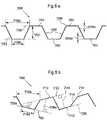
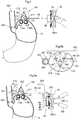
- the stretching devicecomprises a first engaging member adapted to engage a first part of the stomach wall and a second engaging member adapted to engage a second part of the stomach wall close to but spaced from the first stomach part.
- the operation deviceis adapted to operate the first and second engaging member to move away from each other to stretch the stomach wall portion between the first and second parts of the stomach such that satiety is created.
- At least one of the first and second engaging membersmay be adapted to at least in part be invaginated by the stomach wall by stomach-to-stomach sutures or staplers holding the engaging member in place.
- At least one of the first and second engaging membersmay be adapted to be kept in place by sutures or staplers between the engaging member and the stomach wall
- at least one of the first and second engaging memberscomprises a tissue growth promoting structure, preferably a net like structure, adapted to be in contact with the stomach wall to secure long term attachment of the stretching device to the stomach wall,
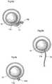
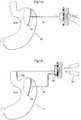
- the stretching devicecomprises at least one expandable body adapted to be invaginated by a portion of the patient's stomach wall
- the operation devicecomprises a fluid reservoir, which is in fluid communication with a chamber of the body.
- the operation deviceis non-invasively operable to distribute fluid from the fluid reservoir to the chamber of the body to expand the body such that the stomach wall portion is stretched, when the body is invaginated.
- the fluid reservoirmay be operated by manually pressing it.
- the operation devicemay comprise a reverse servo, wherein a small volume of fluid in the fluid reservoir is compressed with a higher force and the chamber of the body creates a movement of a larger total volume with less force per unit of volume.
- the fluid reservoirmay be placed subcutaneously or in the abdomen, and may be regulated by moving a wall of the reservoir, for example by a motor.
- a pumpmay be provided for pumping fluid or air from the reservoir to the body's chamber,
- reversed servo meansencompasses the definition of a device that is controlled with a higher force and a small stroke i.e. for example movement of a small amount of fluid with a high force controls a larger amount of fluid moving by means of very smaller force, but may alternatively or additionally encompass the definition of a mechanism that transfers a strong force acting on a moving element having a short stroke into a small force acting on another moving element having a long stroke.
- the reversed servo meansis preferably used when manual control of the device through intact skin is possible.
- the devicecomprises a large chamber in contact with one or more smaller chambers.
- the chambersare adapted to communicate with fluid or air being distributed between the chambers.
- a reversed servo for distributing fluid between the chambersmay be provided, wherein a small volume of fluid in the large chamber is compressed with a higher force and the smaller chamber creates a movement of a larger total volume with less force per unit of volume.
- the large chambermay be adapted to be invaginated in the patient's fundus stomach wall to also treat reflux disease by restricting movement of the cardiac notch towards the diaphragm muscle of the patient, whereas the small chambers function as stretching devices to treat obesity.
- the large chambermay distribute fluid or air to the small chambers to cause them to expand and stretch the stomach fundus wall.
- the stretching devicecomprises a mechanical stretching device, wherein a motor for mechanically regulating the stretching device may be provided.
- the mechanically regulated stretching devicemay be adapted to engage a first part of the stomach wall and a second part of the stomach, wherein the mechanically regulated stretching device comprises a joint mechanism adapted to be moved by the operation device.
- the stretching devicemay comprise a first engaging member adapted to engage a first part of the stomach wall and a second engaging member adapted to engage a second part of the stomach wall close to but spaced from the first stomach part, wherein the mechanical stretching device regulates the distance between the first and second parts of the stomach wall.
- the hydraulic means described abovemay be used for regulating such a mechanical stretching device by the hydraulic distribution of fluid or air.
- the stretching devicemay be non-invasively adjustable postoperatively.
- the operation device for operating the stretching devicemay in its simplest form comprise a subcutaneous switch adapted to be non-invasively operated by manually pressing the switch for the operation of the stretching device.
- At least two operable stretching devices adapted to stretch at least two different portions of the stomach wallmay be provided, wherein the device is adapted to be postoperatively and non-invasively regulated. Specifically, the device may be regulated from time to time such that at a first time one of the stretching devices stretches one of the portions of the stomach wall and at a second time the other of the stretching devices stretches the other portion of the stomach wall.
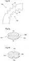
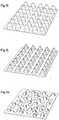
- the stretching devicecomprises a body adapted to fill out a volume defined by wall portions of the stomach.
- the bodysuitably has rounded contours without too sharp edges that would be damaging to the patient's stomach wall.
- the bodymay have varying circumference to better be kept in place invaginated by stomach wall portions of the patient.
- the bodymay be shaped like an egg or like a kidney.
- any kind of mechanical constructionmay be used. Any mechanical construction driven mechanically or hydraulically or any pneumatic construction may be used. Any motor or any pump or moving material changing form when powered may be used to achieve the simple goal of stretching a part of the stomach wall by moving at least two part s of the stomach wall away from each other.
- any kind of hydraulic operationmay be used. It will be appreciated that instead of hydraulic operation, pneumatic operation can be used, wherein air instead of hydraulic fluid is moved between a reservoir and a chamber formed by the stretching device.
- the reservoirhas a locking position to keep it in the desired position if it is handled by the patient.
- To compress the reservoirit preferably stays compressed and releases after pressing again.
- hydraulic solutionAny kind of hydraulic solution may be used for the stretching device.
- the hydraulic solutionmay be driven by both mechanically and powered with any motor or pump as well as manual.
- stomach wallwhich also may be achieved both mechanically, hydraulically, pneumatically and both being powered with a motor or pump or by manual force.
- a device for treating obesity of a patientcomprises at least one operable stretching device implantable in the patient and adapted to stretch a portion of the patient's stomach wall.
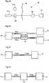
- the devicefurther comprises an implantable control unit for automatically controlling the operable stretching device, when the control unit and stretching device are implanted, to stretch the stomach wall portion in connection with the patient eating such that satiety is created.
- the devicefurther comprises at least two stretching devices, a first stretching device and a second stretching device, or three or more stretching devices.
- the devicefurther comprises an operation device for operating the stretching device, wherein the control unit controls the operation device to stretch the stomach wall portion, when the control unit and stretching device are implanted.
- the devicefurther comprising a sensing device including a sensor for sensing a physical parameter of the patient or a functional parameter of the stretching device, wherein the sensing device sends information relating to the parameter to the control unit, and the control unit controls the stretching device based on the information.
- the devicecould be adapted to control the stretching device to intermittently stretch the stomach wall, when the control unit and stretching device are implanted.
- the implantable control unitis adapted to control the amount of stretching performed by the stretching device on the stomach wall, according to one embodiment by vary over time, the amount of stretching of the stomach wall and/or to stretch the stomach during a predetermined time period.
- the implantable control unitis adapted to control the stretching device based on the patient's food intake
- the implantable control unitcould be programmable to include any of: a predetermined time period during which the stretching device is controlled to stretch the stomach wall, and the magnitude of stretching applied on the stomach wall.
- the operation devicecould be a mechanical operation device, hydraulic operation device, a hydraulically operated mechanical operation device or a mechanically operated hydraulic operation device,
- the sensor of the sensing devicesenses the patient's food intake directly or indirectly, and the implantable control unit controls the operation device to stretch the stomach wall in response to signals from the sensor.
- the implantable control unitis adapted to control the operation device to stretch the stomach wall using more than one stretching device. This could be done by the implantable control unit being adapted to control the first stretching device, during a first time period, to stretch a first portion of the stomach wall, and the second stretching device, during a second time period, to stretch a second portion of the stomach wall different from said first portion of the stomach, to allow longer relaxation of the stomach wall in between stretching periods.
- the sensor of the sensing deviceis adapted to sense a parameter related to the patients food intake such as esophagus movement, esophagus bending, esophagus motility, esophagus stretching, esophagus pressure, food passing esophagus, food in the stomach, neural activity, vagus activity, muscle activity, hormonal activity, stomach motility, stomach stretching, stomach pressure, stomach bending, stomach filling, and/or acidity in the stomach.
- a parameter related to the patients food intakesuch as esophagus movement, esophagus bending, esophagus motility, esophagus stretching, esophagus pressure, food passing esophagus, food in the stomach, neural activity, vagus activity, muscle activity, hormonal activity, stomach motility, stomach stretching, stomach pressure, stomach bending, stomach filling, and/or acidity in the stomach.
- the sensing devicecould also be adapted to senses motility, stretching, bending, pressure, movement, a hormone, neural activity, PH-level, acidity, volume, capacitance, resistance, volt, ampere, light absorption or visualization, ultrasound reflection or absorption, bending metal, bimetal and PH.
- the devicefurther comprises an implantable reservoir, wherein the operation device is hydraulically controlled by the reservoir.
- the stretching devicecould be adapted to be controlled from outside the patient's body using a patient control which according to one embodiment could be adapted to override the control of the implantable control unit.
- the implantable control unitcould be adapted to be controlled from outside the patient's body by the patient.
- the devicefurther comprises an external control unit for controlling the implantable control unit from outside the patient's body e.g. by means of an implantable switch operable by the patient.
- the devicecomprises a wireless remote control for controlling and/or programming the implantable control unit from outside the patient's body.
- the control unitcould comprise a force controller, and the mechanical operation device could be controlled by the force controller.
- the implantable control unitcomprises a pressure controller, and the hydraulic operation device is controlled by the pressure controller.
- the stretching device of the devicecould comprise a first and a second engaging part, the first part could be adapted to be engaged to a first area of the stomach wall, and the second part could be adapted to be engaged to a second area of the stomach wall.
- the stretching deviceis thereby adapted to stretch a portion of the stomach wall between the first area and the second area.
- the stretching devicecould comprise a motor, such as an implantable electrical motor, which in turn could operate at least one joint to move the joint to stretch the stomach wall portion.
- the devicecould comprise a chamber having a variable volume; the chamber could be adapted to receive a fluid,
- the devicecould further comprise a reservoir adapted to hold a fluid and to be in fluid connection with the chamber.
- the stretching devicecould further comprise a pumping device, which could be adapted to move the fluid from the reservoir to the chamber, and thereby stretching the portion of the stomach wall.
- the devicefurther comprises a second fluid connection adapted to enable the fluid to flow back from the chamber to the reservoir during a predetermined time period.
- the stretching devicecomprises a chamber adapted to have a variable volume.
- the chambercould comprise at least one moveable wall portion, which could be an elastic wall portion.
- the chambercould have an essentially round shape and could be adapted to receive a fluid.
- the stretching devicefurther comprises a reservoir adapted to hold a fluid and to be in fluid connection with the chamber
- the stretching devicecould further comprise a pumping device, which could be adapted to move the fluid from the reservoir to the chamber via a first fluid connection interconnecting the reservoir and chamber, thereby stretching the portion of the stomach wall.
- the stretching devicefurther comprises a second fluid connection interconnecting the chamber and reservoir and adapted to enable the fluid to flow back from the chamber to the reservoir during a predetermined time period.
- the reservoir according to any of the examplescould be adapted to be placed subcutaneously or in the abdomen and the reservoir could be controlled by moving a wall of the reservoir which could be done using a motor adapted therefore.
- the chambercould also comprise an electrical motor adapted to expand the volume of the chamber.
- the devicecould further comprise a reverse servo, wherein a small volume in the reservoir is compressed with a higher force and the chamber creates a movement of a larger total area with less force per area unit.
- the sensor implanted in the patient according to any of the embodimentscould be a functional parameter sensor sensing a functional parameter of the device, such as the transfer of energy for charging an internal energy source.
- the sensoris a physical parameter sensor sensing a physical parameter of the patient, such as the food intake of the patient.
- the sensor according to any of the embodimentscould be at least one of body temperature sensors, pressure sensors, blood pressure sensors, blood flow sensors, heartbeat sensors, breathing sensors, electrical conductivity sensors, pH sensor, light sensitive sensors, gas detection sensors and sensors sensing mechanical strain, such as a sensor adapted to sense any of contraction and relaxation of the Cardia.
- the devicefurther comprises a feedback device for sending information from inside the patient's body to the outside thereof to give feedback information related to the functional parameter.
- the deviceis controlled by a control unit adapted to control the stretching device.
- the control unitcould be adapted to control the stretching device, or two or more stretching devices, in response to signals from the sensor.
- control unitcontrols the stretching devices from time to time such that one of the stretching devices at a first time stretches a first portion of the stomach wall and another of the stretching devices at a second time stretches a second portion of the stomach wall.
- the control unitcould be adapted to be controllable from outside of the patient's body, e.g. through a wireless remote control, which in turn could comprises at least one external signal transmitter, which could be adapted to transmit a wireless control signal comprising a frequency, amplitude, or phase modulated signal or a combination thereof.
- the at least one transmitteris adapted to transmit a wireless control signal comprising a analogue or a digital signal, or a combination of an analogue and digital control signal, or a wireless control signal comprising an electric or magnetic field, or a combined electric and magnetic field.
- control unitcould be adapted to be implanted subcutaneously in the human patient, and could be adapted to control a hydraulic system.
- the devicecould further comprise a transferring member for powering the control unit, the transferring member could comprise a fluid transferring member and/or an electrical lead.
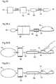
- the devicefurther comprises an external data communicator and an implantable internal data communicator communicating with the external data communicator.
- the internal communicatorcould be adapted to feed data related to the device for treating obesity or the patient back to the external data communicator or the external data communicator feeds data to the internal data communicator.
- the devicecould further comprise a wireless energy transmitter transmitting energy by at least one wireless energy signal, such as a wave signal, e.g. a sound wave signals, ultrasound wave signals, electromagnetic wave signals, infrared light signals, visible light signals, ultra violet light signals, laser light signals, micro wave signals, radio wave signals, x-ray radiation signals and a gamma radiation signals.
- a wireless energy signalsuch as a wave signal, e.g. a sound wave signals, ultrasound wave signals, electromagnetic wave signals, infrared light signals, visible light signals, ultra violet light signals, laser light signals, micro wave signals, radio wave signals, x-ray radiation signals and a gamma radiation signals.
- the wireless energy signalcould further comprise an electric or magnetic field, or a combined electric and magnetic field.
- the devicecomprises an energy source adapted to power the device, which could comprise an internal energy source which in turn could be adapted to receive energy from an external energy source transmitting energy in a wireless mode.
- the internal energy sourcecould further comprise an accumulator, at least one voltage level guard and/or at least one constant current guard.
- the devicecould further comprise an energy-transforming device adapted to transform energy from a first form into a second form.
- the device according to any of the embodimentscould comprise a fixating member, which could be adapted to fixate the stretching device to the stomach wall of the patient.
- the fixating membercould be adapted to be in contact with sutures or staplers for fixating the stretching device to the stomach wall of the patient.
- the fixating membercould comprise a net like structure, which could be adapted to promote growth in of human tissue for long term fixation to the stomach wall.
- the present inventionalso provides an obesity treatment system comprising a device for treating obesity as described above.
- the systemmay comprise a subcutaneous electric switch adapted to manually and non-invasively control a function of the device for treating obesity.
- the systemmay comprise a hydraulic device having a hydraulic reservoir, wherein the device for treating obesity is adapted to non-invasively be regulated by manually pressing the hydraulic reservoir.
- the systemmay comprise a wireless remote control for controlling a function of the device.
- the wireless remote controlcomprises at least one external signal transmitter and an internal signal receiver may be provided to be implanted in the patient.
- the wireless remote controlis adapted to transmit at least one wireless control signal for controlling the device.
- the wireless control signalmay comprise a frequency, amplitude, or phase modulated signal or a combination thereof, and an analogue or a digital signal, or a combination of an analogue and digital signal.
- the wireless control signalcomprises an electric or magnetic field, or a combined electric and magnetic field.
- the remote controlmay transmit a carrier signal for carrying the wireless control signal.
- the carrier signalmay comprise digital, analogue or a combination of digital and analog signals.
- the remote controlmay transmit an electromagnetic carrier wave signal for carrying the digital or analog control signal.
- the systemmay comprise a wireless energy transmitter for non-invasively energizing the device with wireless energy.
- the energy transmittertransmits energy by at least one wireless energy signal.
- the wireless energy signalmay comprise a wave signal selected from the following: a sound wave signal, an ultrasound wave signal, an electromagnetic wave signal, an infrared light signal, a visible light signal, an ultra violet light signal, a laser light signal, a micro wave signal, a radio wave signal, an x-ray radiation signal and a gamma radiation signal.
- the wireless energy signalcomprises an electric or magnetic field, or a combined electric and magnetic field.
- the wireless energy transmittermay transmit a carrier signal for carrying the wireless energy signal.
- the carrier signalmay comprise digital, analogue or a combination of digital and analog signals.
- the systemmay comprise an energy-transforming device for transforming the wireless energy from a first form into a second form energy.
- the energy-transforming devicemay directly during energy transfer operate the device with the second form energy.
- the second form energymay comprise a direct current or pulsating direct current, or a combination of a direct current and pulsating direct current.
- the second form energymay comprise an alternating current or a combination of a direct and alternating current.
- An accumulatormay be provided, wherein the second form energy is used at least partly to charge the accumulator.
- the energy of the first or second formmay comprise magnetic energy, kinetic energy, sound energy, chemical energy, radiant energy, electromagnetic energy, photo energy, nuclear energy or thermal energy.
- One of the energy of the first form and the energy of the second formmay be non-magnetic, non-kinetic, non-chemical, non-sonic, non-nuclear or non-thermal.
- the systemmay comprise an energy source adapted to power the device.
- the energy sourcemay comprise an internal energy source adapted to receive energy from an external energy source transmitting energy in a wireless mode.
- the internal energy sourceis charged by the energy in the wireless mode.
- the systemmay comprise a feedback device for sending information from inside the patient's body to the outside thereof to give feedback information related to a functional parameter.
- the systemmay comprise a sensor sensing a parameter, such as a functional parameter of the system, which is correlated to the transfer of energy for charging an internal energy source.
- An internal control unitmay be provided for controlling the operation device of the device in response to the sensor sensing a functional parameter.
- sensorsenses a physical parameter of the patient.
- the physical parametermay be one of body temperature, blood pressure, blood flow, heartbeats and breathing.
- the physical parameter sensormay be a pressure or motility sensor, or a sensor sensing measure, bending, stretching or food intake.
- the internal control unitmay control the operation device in response to the sensor sensing the physical parameter.
- An internal control unitmay be provided for receiving information from the sensor.
- the operation device of the devicemay comprise a motor or a pump. Specifically, the operation device may comprise an electric motor.
- the operation devicemay be electrically powered, may be a hydraulic operation device or may be a pneumatic operation device.
- the transmitted energy, directly in its wireless formmay affect the operation device to create kinetic energy to operate the stretching device of the device during energy transfer.
- the systemmay comprise a feedback device for sending information from inside the patient's body to the outside thereof to give feedback information related to a functional parameter.
- the systemmay comprise an external data communicator and an implantable internal data communicator communicating with the external data communicator, wherein the internal communicator is adapted to feed data related to the device for treating obesity or the patient back to the external data communicator or the external data communicator feeds data to the internal data communicator.
- the systemmay comprise implantable electrical components including at least one voltage level guard and/or at least one constant current guard.
- the present inventionmay be used in methods as listed below:
- the reservoirmay be placed subcutaneously for being reached by the patients hand for moving fluid manually to or from the stretching device.
- the stretching devicemay be powered by an internal energy source for stretching or releasing the stretching device, wherein by means of a control device controlling the power from an internal control unit or from the outside the patient's body.
- a wireless energy transmitter for wireless transfer of energypowers the operation device to get the stretching device to directly during energy transfer cause the stretching device to stretch the stomach wall.
- a wireless energy transmitter for wireless transfer of energycharges the internal energy source.
- a reversed servomay be provided, wherein moving, in a closed hydraulic system, a small amount of fluid, a larger movement of fluid is achieved in a second larger closed hydraulic system, wherein the small amount of fluid is moved with by a higher force per area unit than the large volume.
- An invaginated stretching device in the fundus stomach wall of the patientis adapted to be adjustable, wherein the stretching device placed invaginated in the stomach fundus wall is adapted to be adjusted and stretching the stomach fundus wall thereby creating
- the methodmay further comprise sending feedback information from inside the body to the outside thereof to give feedback related to the functional parameters of the device.
- the methodmay further comprise sending feedback information from inside the body to the outside thereof to give feedback related to the physical parameters of the patient.
- the functional parameter of the devicemay be correlated to the transfer of energy for charging the internal energy source.
- the deviceis programmable from outside the patient's body.
- the methodmay further comprise the steps of:
- the methodmay further comprise the steps of:
- the methodmay further comprise subcutaneously placing a reversed servo having a small control reservoir and moving a small volume from the control reservoir with a higher force per area unit, creating a larger movement of the stretching device with less force per area unit.
- the methodmay further comprise performing the non-invasive regulation by manually pressing a subcutaneous switch.
- the methodmay further comprise performing the non-invasive regulation by a wireless remote control.
- the methodmay further comprise performing the non-invasive regulation by a wireless energy transmitter.
- the methodmay further comprise powering the device for treating obesity by an internal energy source.
- the methodmay further comprise powering the device for treating obesity by an external energy source transmitting wireless energy, wherein the energy source comprises an external energy source transmitting wireless energy.
- the methodmay further comprise transmitting wireless energy from an external energy source to charge a rechargeable internal energy source.
- a device for treating obesity of a patientcomprises at least one operable stretching device implantable in the patient and adapted to stretch a portion of the patient's stomach wall.
- the devicefurther comprises an implantable control unit for automatically controlling the operable stretching device, when the control unit and stretching device are implanted, to stretch the stomach wall portion in connection with the patient eating such that satiety is created.
- the devicefurther comprises at least two stretching devices, a first stretching device and a second stretching device, or three or more stretching devices.
- the devicefurther comprises an operation device for operating the stretching device, wherein the control unit controls the operation device to stretch the stomach wall portion, when the control unit and stretching device are implanted.
- the devicefurther comprising a sensing device including a sensor for sensing a physical parameter of the patient or a functional parameter of the stretching device, wherein the sensing device sends information relating to the parameter to the control unit, and the control unit controls the stretching device based on the information.
- the devicecould be adapted to control the stretching device to intermittently stretch the stomach wall, when the control unit and stretching device are implanted.
- the implantable control unitis adapted to control the amount of stretching performed by the stretching device on the stomach wall, according to one embodiment by vary over time, the amount of stretching of the stomach wall and/or to stretch the stomach during a predetermined time period.
- the implantable control unitis adapted to control the stretching device based on the patient's food intake
- the implantable control unitcould be programmable to include any of: a predetermined time period during which the stretching device is controlled to stretch the stomach wall, and the magnitude of stretching applied on the stomach wall.
- the operation devicecould be a mechanical operation device, hydraulic operation device, a hydraulically operated mechanical operation device or a mechanically operated hydraulic operation device.
- the sensor of the sensing devicesenses the patient's food intake directly or indirectly, and the implantable control unit controls the operation device to stretch the stomach wall in response to signals from the sensor.
- the implantable control unitis adapted to control the operation device to stretch the stomach wall using more than one stretching device, This could be done by the implantable control unit being adapted to control the first stretching device, during a first time period, to stretch a first portion of the stomach wall, and the second stretching device, during a second time period, to stretch a second portion of the stomach wall different from said first portion of the stomach, to allow longer relaxation of the stomach wall in between stretching periods.
- the sensor of the sensing deviceis adapted to sense a parameter related to the patients food intake such as esophagus movement, esophagus bending, esophagus motility, esophagus stretching, esophagus pressure, food passing esophagus, food in the stomach, neural activity, vagus activity, muscle activity, hormonal activity, stomach motility, stomach stretching, stomach pressure, stomach bending, stomach filling, and/or acidity in the stomach,
- the sensing devicecould also be adapted to senses motility, stretching, bending, pressure, movement, a hormone, neural activity, PH-level, acidity, volume, capacitance, resistance, volt, ampere, light absorption or visualization, ultrasound reflection or absorption, bending metal, bimetal and PH.
- the devicefurther comprises an implantable reservoir, wherein the operation device is hydraulically controlled by the reservoir.
- the stretching devicecould be adapted to be controlled from outside the patient's body using a patient control which according to one embodiment could be adapted to override the control of the implantable control unit.
- the implantable control unitcould be adapted to be controlled from outside the patient's body by the patient.
- the devicefurther comprises an external control unit for controlling the implantable control unit from outside the patient's body e.g. by means of an implantable switch operable by the patient.
- the devicecomprises a wireless remote control for controlling and/or programming the implantable control unit from outside the patient's body.
- the control unitcould comprise a force controller, and the mechanical operation device could be controlled by the force controller.
- the implantable control unitcomprises a pressure controller, and the hydraulic operation device is controlled by the pressure controller.
- the stretching device of the devicecomprises a first and a second engaging part, the first part is adapted to be engaged to a first area of the stomach wall, and the second part is adapted to be engaged to a second area of the stomach wall.
- the stretching deviceis thereby adapted to stretch a portion of the stomach wall between the first area and the second area.
- the stretching devicecould comprise a motor, such as an implantable electrical motor, which in turn could operate at least one joint to move the joint to stretch the stomach wall portion.
- the devicecould comprise a chamber having a variable volume; the chamber could be adapted to receive a fluid,
- the devicecould further comprise a reservoir adapted to hold a fluid and to be in fluid connection with the chamber.
- the stretching devicecould further comprise a pumping device, which could be adapted to move the fluid from the reservoir to the chamber, and thereby stretching the portion of the stomach wall,
- the devicefurther comprises a second fluid connection adapted to enable the fluid to flow back from the chamber to the reservoir during a predetermined time period.
- the stretching devicecomprises a chamber adapted to have a variable volume.
- the chambercould comprise at least one moveable wall portion, which could be an elastic wall portion.
- the chambercould have an essentially round shape and could be adapted to receive a fluid.
- the stretching devicefurther comprises a reservoir adapted to hold a fluid and to be in fluid connection with the chamber
- the stretching devicecould further comprise a pumping device, which could be adapted to move the fluid from the reservoir to the chamber via a first fluid connection interconnecting the reservoir and chamber, thereby stretching the portion of the stomach wall.
- the stretching devicefurther comprises a second fluid connection interconnecting the chamber and reservoir and adapted to enable the fluid to flow back from the chamber to the reservoir during a predetermined time period
- the reservoir according to any of the examplescould be adapted to be placed subcutaneously or in the abdomen and the reservoir could be controlled by moving a wall of the reservoir which could be done using a motor adapted therefore.
- the chambercould also comprise an electrical motor adapted to expand the volume of the chamber.
- the devicecould further comprise a reverse servo, wherein a small volume in the reservoir is compressed with a higher force and the chamber creates a movement of a larger total area with less force per area unit.
- the sensor implanted in the patient according to any of the embodimentscould be a functional parameter sensor sensing a functional parameter of the device, such as the transfer of energy for charging an internal energy source.
- the sensoris a physical parameter sensor sensing a physical parameter of the patient, such as the food intake of the patient.
- the sensor according to any of the embodimentscould be at least one of body temperature sensors, pressure sensors, blood pressure sensors, blood flow sensors, heartbeat sensors, breathing sensors, electrical conductivity sensors, pH sensor, light sensitive sensors, gas detection sensors and sensors sensing mechanical strain, such as a sensor adapted to sense any of contraction and relaxation of the Cardia.
- the devicefurther comprises a feedback device for sending information from inside the patient's body to the outside thereof to give feedback information related to the functional parameter.
- the deviceis controlled by a control unit adapted to control the stretching device.
- the control unitcould be adapted to control the stretching device, or two or more stretching devices, in response to signals from the sensor.
- control unitcontrols the stretching devices from time to time such that one of the stretching devices at a first time stretches a first portion of the stomach wall and another of the stretching devices at a second time stretches a second portion of the stomach wall
- the control unitcould be adapted to be controllable from outside of the patient's body, e.g. through a wireless remote control, which in turn could comprises at least one external signal transmitter, which could be adapted to transmit a wireless control signal comprising a frequency, amplitude, or phase modulated signal or a combination thereof.
- the at least one transmitteris adapted to transmit a wireless control signal comprising a analogue or a digital signal, or a combination of an analogue and digital control signal, or a wireless control signal comprising an electric or magnetic field, or a combined electric and magnetic field.
- control unitcould be adapted to be implanted subcutaneously in the human patient, and could be adapted to control a hydraulic system.
- the devicecould further comprise a transferring member for powering the control unit, the transferring member could comprise a fluid transferring member and/or an electrical lead.
- the devicefurther comprises an external data communicator and an implantable internal data communicator communicating with the external data communicator.
- the internal communicatorcould be adapted to feed data related to the device for treating obesity or the patient back to the external data communicator or the external data communicator feeds data to the internal data communicator.
- the devicecould further comprise a wireless energy transmitter transmitting energy by at least one wireless energy signal, such as a wave signal, e.g. a sound wave signals, ultrasound wave signals, electromagnetic wave signals, infrared light signals, visible light signals, ultra violet light signals, laser light signals, micro wave signals, radio wave signals, x-ray radiation signals and a gamma radiation signals.
- a wireless energy signalsuch as a wave signal, e.g. a sound wave signals, ultrasound wave signals, electromagnetic wave signals, infrared light signals, visible light signals, ultra violet light signals, laser light signals, micro wave signals, radio wave signals, x-ray radiation signals and a gamma radiation signals.
- the wireless energy signalcould further comprise an electric or magnetic field, or a combined electric and magnetic field.
- the devicecomprises an energy source adapted to power the device, which could comprise an internal energy source which in turn could be adapted to receive energy from an external energy source transmitting energy in a wireless mode.
- the internal energy sourcecould further comprise an accumulator, at least one voltage level guard and/or at least one constant current guard.
- the devicecould further comprise an energy-transforming device adapted to transform energy from a first form into a second form.
- the device according to any of the embodimentscould comprise a fixating member, which could be adapted to fixate the stretching device to the stomach wall of the patient.
- the fixating membercould be adapted to be in contact with sutures or staplers for fixating the stretching device to the stomach wall of the patient.
- the fixating membercould comprise a net like structure, which could be adapted to promote growth in of human tissue for long term fixation to the stomach wall.
- a device adapted to stretch a part of the stomach wall of the patient in a gastroscopic method of treating obesity of a patientcomprises the steps of: inserting the device into the stomach of the patient through the esophagus, placing the device in contact with the stomach wall, fixating the device to the stomach wall such that the device can stretch a part of the stomach wall.
- the step of fixating the devicecomprises the steps of: fixating a first portion of the device to a first part of the stomach wall, and fixating a second portion of the device to a second part of the stomach wall.
- the step of fixating the first and second portion of the devicecould comprise the step of invaginating the first and second portion with stomach to stomach sutures or staples.
- the methodcomprises the additional steps of: placing a second device adapted to stretch a portion of the stomach wall in contact with the stomach, fixating the second device to the stomach wall, stretching a first portion of the stomach wall using the first device, and stretching a second part of the stomach wall using the second device.
- the stretching of the second portioncomprises the step of: time delaying stretching the second part, with a predetermined time delay.
- the methodcould further comprise the steps of: inserting a gastroscope into the stomach of the patient, pushing a portion of the stomach wall to prepare a pouch on the outside of the stomach, inserting the device into the pouch, placed on the inside of the stomach wall, suturing or stapling to enclose the device in the pouch before or after the insertion of the device into the pouch.
- the methodfurther comprises the steps of: inserting a gastroscope into the stomach of the patient, pulling a portion of the stomach wall to prepare a pouch on the inside of the stomach, creating a hole in the stomach wall into the pouch, inserting the device into the pouch, through the hole in the stomach wall, suturing or stapling the pouch, before or after the insertion of the device through the hole.
- the methodcould further comprise the step of placing a transferring member from the device to a control unit, which could be a fluid transferring member and/or a member adapted to transfer electrical power.
- the methodcould further comprise the step of placing a control unit, which can be placed subcutaneously in the patient.
- the step of placing a transferring member from the device to a control unitcomprises the steps of: cutting an opening in the abdomen of the patient, connecting the transferring member to the control unit, inserting the control unit into the opening in the skin of the patient, and fixating the control unit subcutaneously.
- the methodfurther comprises the step of placing a transferring member from the device to a control unit comprises the steps of: cutting an opening in the abdomen of the patient, connecting the transferring member to the control unit, inserting the control unit into the opening in the skin of the patient, to be placed in the abdominal cavity.
- the step of placing the control unitcould comprise the steps of: fixating the control unit to the abdominal wall.
- the methodcomprises the additional step of postoperatively and non-invasively regulating the device to stretch a portion of the stomach wall to affect the appetite of the patient.
- the step of postoperatively and non-invasively regulating the device to stretch a part of the stomach wallcomprises the step of increasing the distance between the first part of the stomach wall and the second part of the stomach wall.
- the step of regulating the deviceis performed from outside the patient's body, whereas according to other examples the method step of regulating the device comprises regulating the device by the implantable control unit from inside the body.
- the step of regulating the devicecomprises from time to time regulate different devices to at a first time stretch a first portion of the stomach wall and at a second time stretch a second portion of the stomach wall.
- the methodcomprises placing two or more devices in contact with the stomach and from time to time regulate different device to stretch a part of the stomach wall.
- the step of placing a device in contact with the stomachcould comprise placing a device adapted to have a variable volume in contact with the stomach, the volume could be variable through at least one moveable wall portion, which in turn could be at least one elastic wall portion.
- the device according to any of the embodimentscould have an essentially round shape, or an egg shape.
- the devicecould further comprise a subcutaneous switch, and the method could further comprise pressing the switch for manually and non-invasively regulating the device,
- the step of regulating the devicecomprises the step of moving a fluid from a reservoir to the device.
- the devicecould comprise a pump, and the method could comprise the step of; pumping a fluid from the reservoir to the device to stretch the stomach wall.
- the step of moving a fluid from a reservoir to the devicecould comprise the step of moving a wall portion of the reservoir.
- the step of regulating the devicecould comprise the step of manually pressing the reservoir, which could be placed subcutaneously or in the abdomen.
- the step of increasing the distance between the first part of the stomach wall and the second part of the stomach wallcomprises the step of moving fluid into a chamber having a variable volume.
- the step of placing a device in contact with the stomachcomprises placing a device adapted to have a variable volume in contact with the stomach.
- the devicecould be adapted to have a variable volume comprising at least one moveable wall portion, which could comprise at least one elastic wall portion.
- the devicecould have an essentially round shape, or an essentially egg-like shape.
- the devicecould further comprise a subcutaneous switch, and the method could further comprise pressing the switch for non-invasively regulating the device.
- the step of regulating the devicecould comprise the step of moving a fluid from a reservoir to the device, which in turn could comprise the steps of: operating a pumping device, the pumping device moving the fluid from the reservoir to the device, and the device expanding in volume and thereby stretching the portion of the stomach wall.
- the methodcould further comprise the step of the fluid flowing back from the device to the reservoir, thereby releasing the stretching of the stomach wall.
- the methodcould comprise the step of: sensing a variable using an implantable sensor, interpreting the sensed variable and using the interpreted variable to control the device.
- the step of controlling the devicecomprises the steps of: operating a pumping device, for moving the fluid from a reservoir to the device, and the device expanding in volume and thereby stretching the portion of the stomach wall.
- the methodcomprises the step of the fluid flowing back from the device to the reservoir thereby releasing the stretching of the stomach wall.
- the step of sensing a variablecould comprise the step of sensing a variable connected to the food intake of the patient, which step could comprise the step of sensing a variable connected to the food intake of the patient is resulting in a increased stretching of the stomach portion, and thereby feeling of satiety by the patient.
- the step of increasing the distance between the first part of the stomach wall and the second part of the stomach wallcomprises the step of moving fluid into a chamber having a variable volume.
- the methodcould further comprise the step of moving fluid from a reservoir to the chamber having a variable volume.
- the step of moving a fluid from a reservoir to the devicecould comprise the steps of: operating a pumping device, the pumping device moving the fluid from the reservoir to the device, and the device expanding in volume and thereby stretching the portion of the stomach wall.
- the step of operating the pumping devicecomprises the step of operating the pumping device using a wireless remote control.
- the methodfurther comprises the step of the fluid flowing back from the device to the reservoir thereby releasing the stretching of the stomach wall.
- the step of increasing the distance between the first part of the stomach wall and the second part of the stomach wallcomprises the step of operating a motor adapted increase the distance between the first part of the stomach wall and the second part of the stomach wall, thereby stretching a portion of the stomach wall.
- Operating the motorcould comprise the step of operating the motor using a wireless remote control.
- the methodfurther comprises the step of: sensing a variable using an implantable sensor, interpreting the sensed variable, using the interpreted variable to control the device.
- the methodcomprises the steps of: operating a pumping device, the pumping device moving the fluid from a reservoir to the chamber, and the chamber being filled with the fluid increasing the distance between the first part of the stomach wall and the second part of the stomach wall and thereby stretching the portion of the stomach wall,
- the methodfurther comprises the step of the fluid flowing back from the device to the reservoir thereby releasing the stretching of the stomach wall.
- the step of sensing a variablecomprises the step of sensing a variable connected to the food intake of the patient.
- the methodfurther comprises the step of: sensing a variable using an implantable sensor, interpreting the sensed variable, using the interpreted variable to control the device.
- the step of sensing a variablecould comprise the step of sensing a variable connected to the food intake of the patient.
- the step of increasing the distance between the first part of the stomach wall and the second part of the stomach wallcould comprise the step of operating a mechanical device adapted increase the distance between the first part of the stomach wall and the second part of the stomach wall, thereby stretching a portion of the stomach wall.
- the devicecomprises mechanical members adapted to move for stretching a portion of the stomach wall between the first and second part of the stomach wall.
- the mechanical memberscould be moving for stretching a portion of the stomach wall using the motor.
- the step of stretching a portion of the stomach wallcomprises the step of operating at least one mechanical device for stretching a portion of the stomach wall.
- the methodcomprises the step of invaginating the mechanical device in the stomach wall with stomach to stomach sutures.
- the methodcomprises the step of expanding the mechanical device in the invaginated stomach wall to stretch the stomach wall.
- the methodcomprises a motor, expanding the stomach wall
- the methodcomprise a memory metal, expanding the stomach wall.
- the methodcomprises a hydraulically controlled mechanical device, expanding the stomach wall.
- the step of placing a devicecomprises placing the device in connection with the stomach wall, on the outside thereof, which could comprise the step of placing the device in the stomach fundus wall of the patient.
- the step of placing a devicecould comprise the step of placing the device in connection with the stomach wall, on the inside thereof, which could comprise the step of placing the device in the stomach fundus wall of the patient.
- the step of fixating the at least one devicecomprises suturing or stapling the at least one device to the stomach wall.
- the step of fixating the at least one devicecould comprise in-vaginating in the stomach wall with stomach-to-stomach sutures or staples, in other examples the step of fixating the at least one device could comprise placing a mesh adapted to be fixated to the stomach wall by means of fibrotic tissue.
- the meshcould be additionally supported by sutures or staples and could comprise a structure adapted to promote the growth in of human tissue, such as a net like structure.
- An additional methodcomprises the steps of: creating a hole in the stomach wall; introducing the stretching device into the stomach by means of a instrument; moving the device through the hole and placing it on the outside of the stomach wall; creating a pouch of a portion of the stomach wall inside the stomach cavity, with the device placed against the outside of the stomach wall; invaginating the device in the pouch to the stomach wall; and sealing the hole, preferably with sutures or staples.
- An additional methodcomprises the steps of: creating a hole in the stomach wall; creating, by means of the instrument, a pouch of a portion of the stomach wall on the inside of the stomach cavity; introducing the device into the stomach by means of the instrument; moving the device through the hole and placing it on the outside of the stomach wall; introducing the device by means of the instrument into the pouch; invaginating the device to the stomach wall; and sealing the hole, preferably with sutures or staples.
- the methodfurther comprises providing a device for regulating the stretching device from the outside of the patient's body; and operating the device to regulate the device.
- the methodfurther comprises the steps of: cutting the skin of the patient, inserting a tube into the abdominal cavity of the patient, connecting the tube to the volume filling device, filling the device with fluid injected through the tube.
- the methodfurther comprises the steps of: subcutaneously placing an injection port and connecting the tube to the injection port.
- the methodfurther comprises the step of providing a tube connected to the stretching device through the hole and further up to the abdominal wall or passing through the abdominal wall.
- the methodfurther comprises the steps of: cutting the skin of the patient, receiving the tube from the abdominal cavity of the patient, connected to the stretching device, and filling the device with fluid injected through the tube.
- the methodfurther comprises the steps of: subcutaneously placing an injection port, and connecting the tube to the injection port.
- An instrument for placing a device adapted to stretch a part of the stomach wall of a patient in connection with the stomach wallcomprises: a holding member adapted to releaseably hold the device, an insertion member adapted to insert the device through the stomach wall, and a fixating member, adapted to assist in the fixation of the device to the stomach wall, on the outside thereof.
- the instrumentcould further comprise a cutting member for cutting a hole in the stomach wall, an optical member for viewing in the area of the stomach.
- the fixation membercould be adapted for suturing the device to the stomach wall, on the inside thereof, or for stapling the device to the stomach wall, on the inside thereof, or for invaginating at least a part of the device in the stomach wall with stomach-to-stomach sutures, on the inside thereof, or for invaginating at least a part of the device in the stomach wall with stomach-to-stomach staplers, on the inside thereof, however the instrument could be adapted to perform the method from the outside thereof.
- the instrumentcould further comprise a special holding device, which could comprise a special holding device adapted to hold the stomach using vacuum or using mechanical holding members.
- a device adapted to stretch a portion of the stomach wall of the patient in a surgical or laparoscopic method of treating obesity of a patientcomprises the steps of: cutting a hole in the abdominal wall of the patient, dissecting an area around the stomach, placing the device in contact with the stomach, and fixating, direct or indirect, through invagination of the stomach wall the, device to the stomach wall such that the device can stretch a portion of the stomach wall.
- the step of fixating the devicecomprises the steps of: fixating a first portion of the device to a first part of the stomach wall, and fixating a second portion of the device to a second part of the stomach wall, wherein the first and second portion of the device is fixated, such that the device is adapted to stretch a portion of the stomach wall between the first and second part of the stomach wall.
- the deviceis a first device
- the methodcomprises the additional steps of: fixating direct or indirect through invagination of the stomach wall a second device adapted to stretch a part of the stomach wall in contact with the stomach, fixating the second device to the stomach wall, stretching a first portion of the stomach wall using the first device, and stretching a second portion of the stomach wall using the second device,
- the methodcomprises the additional step of postoperatively and non-invasively regulating the device to stretch a portion of the stomach wall to affect the appetite of the patient.
- a device adapted to stretch a portion of the stomach wall of the patient in a surgical or laparoscopic method of treating obesity of a patientcomprises the steps of: inserting a needle or tube like instrument into the abdomen of the patients body, using the needle or tube like instrument to fill the patient's body with gas, placing at least two laparoscopic trocars in the patient's body, inserting a camera through one of the laparoscopic trocars in the patient's body, inserting at least one dissecting tool through one of the at least two laparoscopic trocars, dissecting an area of the stomach, introducing a device into the abdominal cavity, placing the device on the outside of the stomach wall, engaging the stomach wall.
- the methodcomprises the step of postoperatively and noninvasively regulating the device to stretch a part of the stomach wall comprises the step of increasing the distance between the first part of the stomach wall and the second part of the stomach wall.
- the step of regulating the deviceis performed from outside the patient's body.
- the step of regulating the devicecomprises from time to time regulate different device to at a first time stretch a first portion of the stomach wall and at a second time stretch a second portion of the stomach wall.
- the methodcomprises placing two or more device in contact with the stomach and from time to time regulate different device to stretch a portion of the stomach wall.
- the step of fixating the first and second portion of the devicecould further comprise the step of invaginating the first and second portion with stomach to stomach sutures or staplers.
- the devicefurther comprises an implantable control unit, wherein the method step of regulating the device comprises regulating the device by the implantable control unit from inside the body.
- the stretching of the second portioncomprises the step of: time delaying stretching the second part, with a predetermined time delay.
- the step of placing a device in contact with the stomachcomprises placing a device adapted to have a variable volume in contact with the stomach, which could be regulated by means of at least one moveable wall portion, which in turn could be an elastic wall portion.
- the devicecould have an essentially round shape, or egg shape,
- the devicecomprises a subcutaneous switch, and the method further comprises pressing the switch for manually and non-invasively regulating the device.
- Regulating the devicecould comprise the step of moving a fluid from a reservoir to the device.
- the devicefurther comprises a pump
- the methodfurther comprises the step of; pumping a fluid from the reservoir to the device to stretch the stomach wall.
- the step of moving a fluid from a reservoir to the devicecomprises the step of moving a wall portion of the reservoir, which could be done through the step of manually pressing the reservoir.
- the reservoiraccording to any of the examples could be placed subcutaneously or in the abdomen.
- the step of increasing the distance between the first part of the stomach wall and the second part of the stomach wallcomprises the step of moving fluid into a chamber having a variable volume.
- the step of placing a device in contact with the stomachcomprises placing a device adapted to have a variable volume in contact with the stomach.
- the device adapted to have a variable volumecould comprise at least one moveable wall portion, which in turn could be an elastic wall portion.
- the device according to any of the examplescould comprise a subcutaneous switch, and the method could further comprise pressing the switch for noninvasively regulating the device.
- the step of regulating the devicecomprises the step of moving a fluid from a reservoir to the device.
- the step of moving a fluid from a reservoir to the devicecould comprise the steps of: operating a pumping device, for moving the fluid from the reservoir to the device, and the device expanding in volume and thereby stretching the portion of the stomach wall.
- the methodfurther comprises the step of the fluid flowing back from the device to the reservoir, thereby releasing the stretching of the stomach wall.
- the methodfurther comprises the step of: sensing a variable using an implantable sensor, interpreting the sensed variable, using the interpreted variable to control the device.
- the step of controlling the devicecomprises the steps of: operating a pumping device, for moving the fluid from a reservoir to the device, and the device expanding in volume and thereby stretching the portion of the stomach wall.
- the methodfurther comprises the step of the fluid flowing back from the device to the reservoir thereby releasing the stretching of the stomach wall.
- the step of sensing a variablecould comprise the step of sensing a variable connected to the food intake of the patient, which could result in an increased stretching of the stomach portion, and thereby the feeling of satiety by the patient.
- the step of increasing the distance between the first part of the stomach wall and the second part of the stomach wallcould comprise the step of moving fluid into a chamber having a variable volume.
- the step moving fluid into a chambercomprises the step of moving fluid from a reservoir to the chamber having a variable volume.
- the step of moving a fluid from a reservoir to the devicecomprises the steps of: operating a pumping device, the pumping device moving the fluid from the reservoir to the device, and the device expanding in volume and thereby stretching the portion of the stomach wall.
- the step of operating the pumping devicecomprises the step of operating the pumping device using a wireless remote control.
- the methodfurther comprises the step of the fluid flowing back from the device to the reservoir thereby releasing the stretching of the stomach wall.
- the step of increasing the distance between the first part of the stomach wall and the second part of the stomach wallcomprises the step of operating a motor adapted increase the distance between the first part of the stomach wall and the second part of the stomach wall, thereby stretching a portion of the stomach wall.
- the step of operating the motorcould comprise the step of operating the motor using a wireless remote control.
- the methodcould further comprises the step of: sensing a variable using an implantable sensor, interpreting the sensed variable, using the interpreted variable to control the device.
- the step of controlling the devicecould comprise the steps of: operating a pumping device, for moving the fluid from a reservoir to the chamber, and the chamber being filled with the fluid increasing the distance between the first part of the stomach wall and the second part of the stomach wall and thereby stretching the portion of the stomach wall.
- the methodfurther comprise the step of the fluid flowing back from the device to the reservoir thereby releasing the stretching of the stomach wall.
- the step of sensing a variablecomprises the step of sensing a variable connected to the food intake of the patient.
- the methodfurther comprises the step of: sensing a variable using an implantable sensor, interpreting the sensed variable, using the interpreted variable to control the device.
- the step of sensing a variablecould comprise the step of sensing a variable connected to the food intake of the patient.
- the step of increasing the distance between the first part of the stomach wall and the second part of the stomach wallcould comprise the step of operating a mechanical device adapted increase the distance between the first part of the stomach wall and the second part of the stomach wall, thereby stretching a portion of the stomach wall.
- the first and second portions of the devicecould comprise mechanical members adapted to move for stretching a portion of the stomach wall between the first and second part of the stomach wall.
- the methodcomprises a motor, wherein the mechanical members is moving for stretching a portion of the stomach wall using the motor.
- the step of stretching a portion of the stomach wallcomprises the step of operating at least one mechanical device for stretching a portion of the stomach wall.
- the step of invaginating the mechanical device in the stomach wallcomprises invaginating with stomach to stomach sutures.
- the methodfurther comprises the step of expanding the mechanical device in the invaginated stomach wall to stretch the stomach wall.
- the invaginated mechanical devicecomprises a motor, expanding the invaginated mechanical device.
- the devicecould further comprise a memory metal or a hydraulically controlled mechanical device, expanding the stomach wall,
- the step of placing a devicecomprises placing the device in connection with the stomach wall, on the outside thereof, or in the stomach fundus wall, or in connection with the stomach wall, on the inside thereof.
- the step of placing a device in connection with the stomach wall, on the inside thereofcould comprise the steps of: cutting a hole in the stomach wall, and inserting the device through the hole in the stomach wall.
- the step of placing a devicecomprises placing the device in the stomach fundus wall of the patient.
- the step of fixating the at least one devicecomprises suturing or stapling the at least one device to the stomach wall, e.g. by means of stomach-to-stomach sutures or staplers.
- the step of fixating the at least one devicecould comprise placing a mesh adapted to be fixated to the stomach wall by means of fibrotic tissue.
- the meshcould be additionally supported by sutures or staplers and adapted to promote the growth in of human tissue, such as a net like structure.
- the methodcould comprise the step of placing a transferring member from the device to a control unit.
- the transferring membercould comprise a fluid transferring member, or a transferring member adapted to transfer electrical power.
- the methodfurther comprises the step of placing the control unit, which could be placed subcutaneously in the patient.
- step of placing the control unit subcutaneouslyfurther comprises the steps of: inserting the control unit into the hole in the abdomen of the patient, and fixating the control unit.
- An additional methodcomprises the steps of: creating a hole in the stomach wall; introducing the stretching device into the abdomen; moving the device through the hole and placing it on the inside of the stomach wall; creating a pouch of a portion of the stomach wall outside the stomach cavity, with the device placed against the inside of the stomach wall; invaginating the device in the pouch to the stomach wall; and sealing the hole, preferably with sutures or staples.
- the methodcould comprise the steps of: creating a hole in the stomach wall; moving the device through the hole and placing it on the inside of the stomach wall; introducing the device by means of the instrument into the pouch; and sealing the hole, preferably with sutures or staplers.
- the methodfurther comprises providing a device for regulating the stretching device from the outside of the patient's body; and operating the device to regulate the device.
- the devicecomprises an implantable control unit and the method further comprises the steps of; providing an implanted control unit for regulating the stretching device from the inside of the patient's body; and operating the device to regulate the device.
- the methodcould further comprise the steps of subcutaneously placing an injection port and connecting a tube connected to the device to the injection port.
- the methodfurther comprises the step of providing a tube connected to the stretching device through the hole and further up to the abdominal wall or passing through the abdominal wall.
- the methodfurther comprises the steps of: receiving a tube from the abdominal cavity of the patient, connected to the stretching device, and filling the device with fluid injected through the tube,
- the methodcould further comprise the steps of: subcutaneously placing an injection port, and connecting the tube to the injection port.
- the methodcould further comprise the additional step of postoperatively and non-invasively regulating the device to stretch a part of the stomach wall to affect the appetite of the patient.
- the methodcomprises the additional step of filling the device with a fluid.
- the methodcould comprise the additional step of placing an internal control unit within the patient's body.
- the methodfurther comprises the additional step of connecting the internal control unit to the device, which could be done hydraulically or using electrical wires.
- a device adapted to stretch a portion of the stomach wall of the patientis used in an additional surgical or laparoscopic method of treating obesity of a patient.
- the methodcomprises the steps of: inserting a needle or tube like instrument into the abdomen of the patients body, using the needle or tube like instrument to fill the patient's body with gas, placing at least two laparoscopic trocars in the patient's body, inserting a camera through one of the laparoscopic trocars in the patient's body, inserting at least one dissecting tool through one of the at least two laparoscopic trocars, dissecting an area of the stomach, introducing a device into the abdominal cavity, invaginating the device on the outside of the stomach wall with stomach to stomach sutures or staplers and postoperatively stretching the invaginated stomach wall portion by operating the device.
- the methodcomprises the additional step of; introducing a second or more device into the abdominal cavity, invaginating the second or more device on the outside of the stomach wall with stomach to stomach sutures or staplers and postoperatively stretching the invaginated stomach wall portion by operating the second or more device.
- the methodcomprises the additional step of; postoperatively stretching the invaginated stomach wall portion at the first or second or more parts of the device independent from each other.
- a device adapted to stretch a portion of the stomach wall of the patient using an additional surgical or laparoscopic method of treating obesity of a patientcomprises the steps of: inserting a needle or tube like instrument into the abdomen of the patients body, using the needle or tube like instrument to fill the patient's body with gas, placing at least two laparoscopic trocars in the patient's body, inserting a camera through one of the laparoscopic trocars in the patient's body, inserting at least one dissecting tool through one of the at least two laparoscopic trocars, dissecting an area of the stomach, introducing a device into the abdominal cavity, invaginating a first part of the stretching device placed on the outside of the stomach wall with stomach to stomach sutures or staplers and invaginating a second part of the stretching device, separate from the first part, placed on the outside of the stomach wall with stomach to stomach sutures or staplers and postoperatively stretching the stomach wall portion between the first and second part by operating the device.
- the methodcomprises the additional step of; introducing a second or more device into the abdominal cavity, invaginating a first part of the stretching second or more device placed on the outside of the stomach wall with stomach to stomach sutures or staplers, invaginating a second part of the second or more stretching device, separate from the first part, placed on the outside of the stomach wall with stomach to stomach sutures or staplers, and postoperatively stretching the stomach wall portion between the first and second part by operating the second or more device.
- the methodcomprises the additional steps of; invaginating a third or more part of the stretching device placed on the outside of the stomach wall, separate from the first or second part, with stomach to stomach sutures or staplers and postoperatively stretching the stomach wall portion between any combination of the first and second part and third or more parts, by operating the device.
- a device adapted to stretch a portion of the stomach wall of the patient using a surgical method of treating obesity of a patientcomprising the steps of: cutting the skin of a human patient, dissecting an area of the stomach, introducing a device into the abdominal cavity, invaginating the device on the outside of the stomach wall with stomach to stomach sutures or staplers, and postoperatively stretching the invaginated stomach wall portion by operating the device.
- the methodcould further comprise the additional step of; introducing a second or more device into the abdominal cavity, invaginating the second or more device on the outside of the stomach wall with stomach to stomach sutures or staplers, and postoperatively stretching the invaginated stomach wall portion by operating the second or more device.
- the methodcomprises the additional steps of; postoperatively stretching the invaginated stomach wall portion at the first or second or more parts of the device independent from each other.
- a device adapted to stretch a portion of the stomach wall of the patientis used in an additional surgical method of treating obesity of a patient.
- the methodcomprising the steps of: cutting the skin of a human patient, dissecting an area of the stomach, introducing a device into the abdominal cavity, invaginating a first part of the stretching device placed on the outside of the stomach wall with stomach to stomach sutures or staplers, invaginating a second part of the stretching device, separate from the first part, placed on the outside of the stomach wall with stomach to stomach sutures or staplers, and postoperatively stretching the stomach wall portion between the first and second part by operating the device.
- the methodcomprises the additional step of; introducing a second or more device into the abdominal cavity, invaginating a first part of the stretching second or more device placed on the outside of the stomach wall with stomach to stomach sutures or staplers, invaginating a second part of the second or more stretching device, separate from the first part, placed on the outside of the stomach wall with stomach to stomach sutures or staplers. and postoperatively stretching the stomach wall portion between the first and second part by operating the second or more device.
- the methodfurther comprises the steps of invaginating a third or more part of the stretching device placed on the outside of the stomach wall, separate from the first or second part, with stomach to stomach sutures or staplers, and postoperatively stretching the stomach wall portion between any combination of the first and second part and third or more parts, by operating the device.
- the methodcomprises the additional steps of postoperatively and noninvasively regulating the device to stretch a part of the stomach wall to affect the appetite of the patient.
- the method according to any examplecould further comprise the step of filling the device with a fluid.
- the methodcomprises the additional step of placing an internal control unit within the patient's body, and connecting the internal control unit to the device, which could be done hydraulically or using electrical wires.
- An instrument for placing a device adapted to stretch a part of the stomach wall of a patient in connection with the stomach wallcomprises: a holding member adapted to releaseably hold the device, and a fixating member, adapted to assist in the fixation of the device to the stomach wall, on the outside thereof.
- the instrumentcould further comprise an optical member for viewing in the area of the stomach.
- the instrumentcould comprise a fixation member adapted to suturing the device to the stomach wall, on the outside thereof.
- the fixation memberis adapted for stapling the device to the stomach wall, on the outside thereof, and in other examples the fixation member is adapted for invaginating at least a part of the device in the stomach wall with stomach-to-stomach sutures, on the outside thereof.
- the fixation membercould be adapted for invaginating at least a part of the device in the stomach wall with stomach-to-stomach staplers, on the outside thereof.
- An instrument for placing a device adapted to stretch a part of the stomach wall of a patient in connection with the stomach wallcomprises: a holding member adapted to releaseably hold the device, an insertion member adapted to insert the device through the stomach wall, and a fixating member, adapted to assist in the fixation of the device to the stomach wall, on the inside thereof.
- the instrumentcould further comprise a cutting member for cutting a hole in the stomach wall, an optical member for viewing in the area of the stomach.
- the fixation membercould be adapted for suturing the device to the stomach wall, on the inside thereof, or for stapling the device to the stomach wall, on the inside thereof, or for invaginating at least a part of the device in the stomach wall with stomach-to-stomach sutures, on the inside thereof, or for invaginating at least a part of the device in the stomach wall with stomach-to-stomach staplers, on the inside thereof.
- the instrumentcould further comprise a special holding device, which could comprise a special holding device adapted to hold the stomach using vacuum or using mechanical holding members.
- a stretching deviceadapted to post-operatively be adjustable and comprising at least one expandable section, wherein the stretching device is adapted to be adjustable between a first collapsed state and a second expanded state.
- the expandable sectionIn the first collapsed state the expandable section is collapsed, and in the second expanded state, the expandable section is expanded.
- the outer surface of said expandable sectiondoes at least partly comprise a surface structure having elevated areas alternating with lowered areas.
- the expandable sectionis adapted to have, in at least one of said first collapsed and second expanded states a first distance between adjacent elevated areas sufficiently extended to prevent growth of fibrotic tissue from directly interconnecting adjacent elevated areas to an extent that compromises the adjustability between a first collapsed and a second expanded state of said stretching device.
- the expandable sectionfurther comprising connecting areas between adjacent elevated and lowered areas, further adapted to have, in at least one of said first collapsed and second expanded states, a second distance between adjacent connecting areas sufficiently extended to prevent growth of fibrotic tissue from directly interconnecting adjacent connecting areas to an extent that compromises the adjustability between a first collapsed and a second expanded state of said stretching device.
- the expandable sectionis hollow or comprises a hollow body.
- the stretching deviceis substantially completely hollow or comprises a hollow body extending along substantially the complete length and/or complete volume of said stretching device.
- Fibrotic tissuecan often have an extension or thickness of about 0,5 mm to about 1,5 mm and hence the distances between relevant surfaces of the elements of the surface structure are suitably greater than about 3 mm, hence greater than about 2 x 1,5 mm. But depending on the circumstances also distances greater than about 1,0 mm to about 3 mm may be sufficient. In cases where the fibrotic tissue can be expected to have an extension or thickness greater than about 1,5 mm the distances between relevant surfaces of the elements of the surface structure are adapted in a suitable manner.
- the surface structuremay comprise elevated and lowered areas and it may be suitable that also a distance between the different planes of the elevated and lowered areas is bigger than a certain threshold to facilitate the collapsible and/or expandable functionality of the stretching device. If said distance is too small, the collapsible and/or expandable functionality of the stretching device may be limited. A suitable interval for said distance is around 0,5 to 10 mm, more suitable around 2-8 mm and most suitable around 3-7 mm.
- the surface structuremay comprise different geometrical elements or shapes and any combination of such elements or shapes as long as the above mentioned conditions for the distances can be met.
- the surface structuremay e.g. comprise ridges and grooves of different shapes. The ridges and grooves may each have a cross-section that is e.g.
- the surface structuremay as well in general comprise a bellows-shaped structure or a surface structure where geometrical objects of the same or different kind(s) are placed on a surface.
- the geometrical objectsmay be practically randomly placed on the surface or according to some scheme.
- stretching deviceswhere this type of surface structure may be suitable, is stretching devices where the stretching device should have the ability to change shape and/or size substantially. Hence, this is a case where the presence of fibrotic tissue substantially could hinder or impede the function of the stretching device. But the surface structure may be used by any stretching device where the characteristics of the surface structure would be advantageous for the stretching device.
- Invaginated in the stomach wallis to be understood as an object being placed inside of a cavity made of stomach wall material.
- the invaginationenables stomach to stomach sutures or staplers which enables the object of be enclosed by means of the human tissue healing.
- Fig. 1shows a first embodiment of an obesity treatment device.
- the devicecomprises a stretching device 10 implanted in a human patient.
- the stretching device 10is invaginated in the wall 12 of the patient's stomach 12 and the body of the stretching device10 is shaped to rest against the wall 12 of the stomach 12 and further has an outer surface suitable to rest against this wall 12.
- This means that the stretching device 10preferably has an essentially round shape to not damage the stomach wall.
- the stomach wall 12is strong so many different shapes and forms may be used.
- the stretching device10can be fixed to the wall 12a of the stomach 12 in a number of different ways. In the embodiment shown in Fig. 1 , the stretching device 10 is invaginated in the stomach wall 12a.
- stomach-to-stomach sutures or staplers 14are applied to keep the in-vagination in the short term. This allows growth of human tissue, keeping the in-vagination in the long term.
- the stomach wall 12 surrounding the stretching device10is stretched since the circumference of the stretching device 10 is increased.
- receptors in the stomach wallindicate that the stomach is full, thereby creating a feeling of satiety to the patient.
- the stretching device10is contracted, the receptors indicate that the stomach is not full, thereby returning the feeling of hunger.
- the expansion and contraction of the stretching device 10can be performed under direct control of the patient. Alternatively, the expansion and contraction can be performed according to a pre-programmed schedule.
- FIG. 1this figure also shows a fluid operation device, i.e., a hydraulic or pneumatic operation device suited for operating the stretching device, which in the following will be described in detail.
- the stretching device 10forms a fluid chamber, in which fluid is allowed to flow.
- the stretching device 10thus forms an expandable chamber that can change the volume it occupies in the stomach wall, thereby forming a hydraulically or pneumatically regulated stretching device 10.
- a regulation reservoir 16 for fluidsis connected to the stretching device10 by means of a conduit 18 in the form of a tube.
- the stretching device10is thereby adapted to be regulated, preferably non-invasively, by moving liquid or air from the regulation reservoir 16 to the chamber formed by the stretching device.
- the regulation reservoir 16can be regulated in several ways.
- the regulation reservoir 16is regulated by manually pressing the regulation reservoir 16.
- the regulation reservoir 16is regulated by moving a wall of the reservoir. It is then preferred that the regulation reservoir 16 is placed subcutaneously and non-invasive regulation is thereby achieved.
- the volume thereofdecreases and hydraulic fluid is moved from the reservoir to the chamber formed by the stretching device10 via the conduit 18, enlarging or expanding the stretching device10.
- an injection 1001 portis furthermore provided.
- the injection portpreferably comprises self sealing membrane, such as a silicone membrane.
- Fig.1further shows a reversed servo system which comprises a regulation reservoir 16 and a servo reservoir 90.
- the servo reservoir 90hydraulically controls a stretching device 10 via a conduit 18. The reverse servo function is described in greater detail in figs. 33-36 Fig.
- FIG. 2ashows the device according to an example in which a motor 40 is adapted to move a wall of the regulation reservoir 16.
- the powered regulation reservoir 16is then preferably placed in the abdomen of the patient.
- a wireless external remote control unit 34b,c and an external energy transmission device34acan be provided to perform non-invasive regulation of the motor via an energy transforming device30, which is adapted to supply an energy consuming operation device, in the present example the motor 40, with energy.
- the remote controlmay comprise a wireless energy transmitter, 34a which also can act as a regulation device for non-invasively regulating the stretching device.
- an internal power source 70 for powering the regulating deviceis provided.
- the internal energy source 70can for example be a chargeable implanted battery or a capacitor or a device for receiving wireless energy transmitted from outside the body of the patient. Different ways of regulating the stretching device10 will be described below with reference to Figs. 13-29 .
- the device as shown in fig. 2afurther comprises a sensor 201 sensing a parameter of the patient or the device preferably connected to the food intake of the patient.
- the sensoris connected to a control assembly 42 by means of a sensor signal transferring member 202.
- the sensorcan be used to regulate said device in a completely automatic way, i.e.
- the deviceresponds to a sensor signal connected to the food intake of the patient, thereby affecting the control assembly to operate the stretching device10 to stretch the stomach wall 12 and thereby creating a feeling of satiety in the patient.
- the sensorcould be adapted to measure the food intake of the patient through any of temperature, blood pressure, blood flow, heartbeats, breathing and pressure and can be placed in the stomach 12, esophagus 203 or in connection with the cardia 204.
- said sensoris a strain gauge measuring contraction and/or relaxation of the cardia 204.
- the device as shown in fig. 2afurther comprises a second conduit 222 for backflow of hydraulic fluid.
- the backflowis adapted to create the desired feeling of satiety for a predetermined time whereafter the hydraulic fluid has flowed back in a quantity large enough for the stretching device not to stretch the stomach wall anymore and thereby the feeling of hunger returns to the patient.
- a suitable time for the processis between 1 and 6 hours.
- the backflowtakes place in the main conduit 18 by means of a valve system connected to said conduit 18.
- an injection 1001 portis furthermore provided.
- the injection port 1001preferably comprises self sealing membrane, such as a silicone membrane.
- Fig. 2bshows the device according to the example of fig. 2a , in a second state in which the stretching device10 is expanded and thereby stretches the stomach wall 12.
- FIG. 3ashows an embodiment, wherein two stretching devices 10" are provided.
- Both stretching devices 10"work according to the principles described above with reference to Fig. 1 . They can be adapted to postoperatively and non-invasively be regulated and adapted to from time to time regulate different stretching devices to at a first time stretch a first part of the stomach wall and at a second time stretch a second part of the stomach wall.
- Such a stretching device10may be used for keeping electronics and/or an energy source and/or hydraulic fluid. Hydraulic fluid from that device may be distributed to several smaller stretching device areas to vary the stretching area from time to time avoiding any possible more permanent stretching effect of the stomach wall. Even mechanically several stretching areas may be used. The example according to fig.
- 3afurther comprises a hydraulic valve shifting device 54, implanted in the patient, for shifting between operating the first and the second stretching device10".
- the alternatingcreates a more sustainable device since the receptors in the stomach wall is stimulated gets a longer time of recovery between the stretches.
- the systemis a manual system controlled by the patient as described before with reference to fig. 1
- the systemis energized using wireless energy as described before with reference to fig. 2a
- Fig. 4a-eshows different embodiments of the stretching device10 adapted to be implanted in a patient.
- the stretching device 10comprises a surface adapted to be in contact with the stomach wall 12 when the device is invaginated in the stomach wall.
- the stretching devicecomprises a fixating member 206 for suturing or stapling the stretching device to the stomach wall.
- the fixating member 206could comprise holes for receiving said sutures or staplers 14, or the fixation device206 could be penetratable such that the sutures or staplers can penetrate the stomach wall and the fixation device206.
- 4cshows the stretching device10 according to an example in which the stretching device10 comprises an inlet member 207 for filling said device with a fluid. Said inlet member is preferably connected to a hydraulic conduit 18 adapted to be invaginated in the stomach wall 12.
- FIG. 4dshows the stretching device 10 according to an example in which the stretching device 10 comprises a holding member 208 adapted to connect to an insertion device when said stretching device 10 is inserted into an invaginated pouch of the stomach wall 12.
- Fig. 4eshows the stretching device10 according to an example in which the stretching device has a slightly oval or egg-shaped shape.
- Fig. 4efurthermore shows the hydraulic conduit 18 attached to said stretching device10.
- Fig. 4fshows the stretching device10 according to an example in which the stretching device is inflatable by a fluid transported through the conduit 18. According to one example shown in fig.
- the conduitcomprises two sections 18a,b wherein the first section 18a is used to pull the stretching device10 into place, and to fill the device10 with a suitable fluid, whereas the second section 18b is used for the operation of said device10.
- Fig. 4gshows the stretching device10 according to the example of fig. 4f in a deflated state. The stretching device10 is inserted through a hole in the stomach wall 12 in its deflated state whereafter the device10 is filled with a suitable fluid for operation
- Fig. 4hshows the stretching device10 according to an example in which the stretching device10 comprises two movable wall portion 223a,b, which are moveable by means of a bellows structure 209 made of a flexible material.
- FIG. 4ishows the stretching device according to an example where the stretching device is expandable by means of four expandable sections 210 symmetrically placed on four places along the surface of the stretching device, as shown in the section image of fig. 4i .
- the expandable sections 210are made of a flexible material for allowing said sections 210 to expand when said stretching device10 is filled with a hydraulic fluid.
- a first distance 708a between two elevated areas 701, see fig. 5ais long enough so as to prevent growth of fibrotic tissue directly connecting two adjacent elevated areas 707, That is, it may be possible that fibrotic tissue grows on the surface of the elevated and lowered areas 701, 702 and the connecting areas 704.
- fibrotic tissueis prevented from growing directly from one elevated area 701 to another adjacent elevated area 701.
- growing directly from one elevated area 701 to another elevated area 701it is e.g. meant that fibrotic tissue grows from one elevated area 701 to another while not or only to a small extent growing on a connecting area 704.
- the first distance 708amay be measured within an interval 704a from the level of an elevated area 701.
- the expression “growing directly from one elevated area 701 to another elevated area 701”also includes the situation that fibrotic tissue grows on adjacent areas, e.g.
- a second distance 708b corresponding to the extension of a lowered area 702has an extension great enough so as to prevent fibrotic tissue from growing directly from one connecting area 704 to another connecting area 704.
- growing directly from one connecting area 704 to another connecting area 704"it is meant that fibrotic tissue grows from one connecting area 704 to another while not or only to a small extent growing on a lowered area 702. In fig.
- first distance 708a, 718ait is meant a distance that is measured substantially from the edge 706, 714 of one elevated area 701, 710 to the edge 706, 714 of an adjacent elevated area 701, 710.
- Measured substantially from the edgemeans that the measurement may be done within a first interval 704a from the level of an elevated area 701, 710, the first interval 704a extending from the level of an elevated area 701, 710 towards the level of an adjacent lowered area 702, 712.
- a second distance 708b, 718b between adjacent connecting areas 704, 716is used.
- a second distance 708b, 718bit is meant a distance that is measured substantially from the connection point between a connecting area 704, 716 and a lowered area 702, 712 to another connection point involving an adjacent connecting area 704, 716.
- Measured substantially from the connection pointmeans that the measurement may be done within a second interval 704b from the level of a lowered area 702, 712, the second interval 704b extending from the level of a lowered area 702, towards the level of an adjacent elevated area 701, 710.
- elevated and lowered areasit is meant areas that lie in different planes 703, 705, 720, 722 where the planes are separated by a distance 707, 724, 728. The planes may be parallel or substantially parallel but may also be non-parallel.
- a distance between the planesmay be defined by a normal 724, 728 to one of the planes 720, 722 where the normal extend to a point on an area in another plane 722, 726 and the distance between the planes is equal to the extension of the normal 724, 728.
- the normal 724, 728extends from a plane 720, 722 to a point which is approximately equally distant from the edges of an area.
- normal 728as example, one may define the normal as in 728a or in 728b.
- the elevated and lowered areasmay have different shapes, they may be plane or substantially plane but they may also have some kind of curved shape.
- the elevated areas 701, 710connect to adjacent lowered areas 702, 712 by means of connecting areas 704, 716.
- the connection between elevated/lowered areas and connecting areas 704, 716may comprise a radius of different sizes, bigger or smaller radii. When the radius is very small there will substantially be an edge 706, 714 connecting the areas.
- the expression "expandable section”implies that said section also is collapsible.
- the stretching device 10at least partly comprises materials which have a high degree of biocompatibility, such materials may be called physiologically inert, biologically inert or biocompatible. Referring in particular to figs.5a and 5b , in the surface structure 700 there may advantageously be a specified first distance 708a, 718a between adjacent elevated areas 701, 710.
- the distance between adjacent elevated areas 701, 710is chosen so that fibrotic tissue cannot bridge the first distance 708a, 718a between adjacent elevated areas 701, 710.
- the first distance 708a, 718a between adjacent elevated areas 701, 710is advantageously big enough to prevent the formation of fibrotic tissue that bridges adjacent elevated areas 701, 710.
- the second distance 708b, 718b between adjacent connecting areas 704, 716is chosen so that fibrotic tissue can not bridge the second distance 708b, 718b between adjacent connecting areas 704, 716.
- the second distance 708b, 718b between adjacent connecting areas 704, 716is advantageously big enough to prevent the formation of fibrotic tissue that bridges adjacent connecting areas 704, 716. It may also be advantageous that a third distance 707, 724, 728a between the different planes 703, 705, 720, 722, 726 of the elevated and lowered areas is bigger than a certain threshold to facilitate the collapsible and/or expandable functionality of the stretching device. If the third distance 707, 724, 728a is too small the collapsible and/or expandable functionality of the stretching device may be limited.
- a suitable interval for the third distance 707, 724, 728ais 0,5 to 10 mm, more suitable 2-8 mm and most suitable 3-7 mm .
- the surface structure 700may include objects or elements of different geometrical shapes, for example ridges of different shapes, embossments of different shapes and other objects which enable a surface structure as described herein.
- the area of the elevated areas 701, 710may be very small while still resulting in a surface structure that has the desired functionality.
- the area of the elevated areas 701, 710may even be almost zero, as exemplified in fig. 5e . Whereas figs.
- FIG. 5a and 5b-5eshow cross sections of examples of surface structures 700
- figs. 5i-5kshow examples of different surface structures 700 in perspective.
- the objects or elements in the surface structure 700may be placed in rows, ordered in some other way, or may be more or less randomly distributed over the surface of the stretching device.
- Different types of objectsmay also be used together in the surface structure 700, e.g. a combination of pyramid shaped and cone shaped objects together with ridges of some shape,
- figs. 5f -5han example of a stretching device 10 is shown where a surface structure 700 is used, the stretching device 10 is not shown in full.
- FIG. 3shows a longitudinal section of the stretching device 10 where 740 denotes the surface structure on the upper side of the stretching device 10 and 742 denotes the surface structure on the under side of the stretching device 10.
- 740denotes the surface structure on the upper side of the stretching device 10
- 742denotes the surface structure on the under side of the stretching device 10.
- the surface structure 742 on the under sidemay have a greater extension than the surface structure 740 on the upper side of the penile prosthesis.
- the surface structures 140 and 142are one example of a bending portion.
- Fig. 5gshows a cross section of the stretching device 10 where the stretching device 10 includes a waist portion 744, where the waist portion comprises waist surface structures 746 and 748.
- the waist portion with the waist surface structures 746 and 748make the stretching device 10 expandable also in the radial direction.
- the stretching device 10may also have a cross section as shown in fig. 10 comprising a waist portion 744 having four waist surface structures 750, 752, 754, 756 further facilitating the ability of the stretching device 10 to be expandable also in the radial direction.
- the cross section in fig. 5gis taken along the line A1-A2 in fig. 5f .
- Fig. 6aillustrates a stretching device10 provided with an inlet port 18b.
- the stretching device10is invaginated in the stomach wall 12 and the inlet port 18b is available for connection to a tube or the like from the abdominal area of the patient.
- the tube or conduit 18can preferably be connected to the control unit 42 or an injection port 1001.
- Fig. 6billustrates an invaginated stretching device10 wherein, instead of an inlet port, a conduit 18 or electrical lead extends into the abdominal area of the patient.
- Fig. 6cshows a section of the stretching device10 and part of the stomach in which the stretching device10 is invaginated.
- the conduit 18 or electric leadis invaginated in the stomach wall 12 by means of stomach to stomach sutures or staplers 14 which creates an entirely sealed pouch of stomach wall tissue in which the stretching device 10 is placed.
- the conduit 18 or electric leadis thereby tunneled in the stomach wall 12 between the inlet port 18b and the volume filling device10.
- the shape of the stretching device10can take many different forms. It will be appreciated that also the material of the stretching device 10 can vary, It is preferred that the stretching device10 is provided with a coating, such as a Parylene, polytetrafluoroethylene (PTFE), or polyurethane coating, or a combination of such coatings, i.e., a multi-layer coating.
- a coatingsuch as a Parylene, polytetrafluoroethylene (PTFE), or polyurethane coating, or a combination of such coatings, i.e., a multi-layer coating.
- the stretching device 110works according to a different principle from that described above with reference to Figs. 1-6 ,
- the stretching device 110here comprises a first fixation portion 110a adapted to have a first fixation at a first position on the stomach wall 12 and a second fixation portion 110b adapted to have a second fixation at a second position on the stomach wall 12.
- fixation portions 110a,bwhich preferably have an essentially round shape and preferably are adapted to be invaginated in the stomach wall 12, are attached to the distal end of a respective leg 211, which in turn are attached at their respective proximal end to an operation device, such as a motor 40.
- the motoris a hydraulic motor, comprising a hydraulic piston, which is connected to a manual operation device described previously with reference to fig. 1 .
- the hydraulic pistonaffects the legs through their connection with a joint 212 placed in the extremity of the leg.
- the stretching device 110is enclosed in a housing 214 protecting the device from the in growth of fibrotic tissue which potentially could damage the function of said device110.
- the stretching device110is adapted to increase the distance between the first position and the second position on the stomach wall 12, thereby stretching the stomach wall 12.
- the first and/or second fixation portions 110a, 110bare adapted to at least partly be invaginated in the stomach wall 12 with stomach-to-stomach sutures or staplers 14 holding the fixation portions 110a,b in place in suspension in relation to the stomach wall 12.
- the first and second positionsmay be sutured or fixated to the stomach wall in many possible ways and the invention covers all possibilities to distend the stomach wall by moving two portions of the stomach wall away from each other and thereby first fixating the device to at least two positions on the stomach wall.
- the soft suspended connection to the stomach wall 12 where fibrotic stomach-to-stomach tissue helps to give a long term stable positionis to prefer.
- just expanding an invaginated part of the stomachalso stretches away the stomach wall 12, which also may be achieved both mechanically, hydraulically, pneumatically and both being powered with a motor or pump or by manual force.
- Any kind of mechanical constructionmay be used and the mechanical example disclosed is one example. Any mechanical construction driven by mechanically or hydraulically or any pneumatic construction may be used. Any motor or any pump or moving material changing form when powered may be used to achieve the simple goal of stretching a part of the stomach wall by moving at least two portions of the stomach wall away from each other. Fig.
- FIG. 8shows the stretching device 110 according to an example in which the stretching device is controlled from an implantable control assembly 42 to which sensor input, as described earlier, in received.
- the stretching deviceis then regulated through the conduit 18 using a pump 44, connected to at least one fluid reservoir 16, 46, and powered from an energy transforming member 30 connected to an receiver of wireless energy 205, placed under the skin 36, or an implantable energy source 70, such as a rechargeable battery.
- the first and/or second fixation portions 210a, 210bexhibit a structure adapted to be in contact with the stomach wall 12 to promote growth in of human tissue to secure the long term placement of the stretching device110 attached to the stomach wall 12.
- This structurepreferably comprises a net like structure 213.
- the fixation portions 210a, 210bmay be adapted to keep the stretching device110 in place by sutures or staplers between the fixation portion and the stomach wall 12 to secure the short term placement of the stretching device110.
- the stretching device110according to the example shown in fig. 9a functions in accordance with the device described with reference to fig. 7 .
- FIG. 9bshows a fixation device213 comprising a net like structure adapted to propagate the growth-in of fibrotic tissue to fixate the two fixating portions to the stomach wall 12.
- Fig. 9cshows the stretching device according to the example of fig. 9a in a second state, in which the two fixating portions have been separated from each other and the stomach 12 has been stretched.
- Fig. 10ashows the stretching device according to an example in which the stretching device is an electrical mechanical stretching device connected to a control assembly 42 through a power supply line 32.
- the power supply line 32is connected to a power transforming device30 in contact with a receiver of wireless energy 205, such as a coil, which receives energy from a transmitter of wireless energy 34a.
- the control assemblymay furthermore comprise a battery 70 for storing energy received from the wireless energy transmission device34a.
- the control assemblyreceives input from a sensor 201, which according to this example is a strain gauge measuring the contraction and/or relaxation of the cardia 204.
- Fig. 10bshows the stretching device10 in further detail.
- the stretching device10comprises a housing having a bellows structure 209 made of a flexible material so as to enable the wall portions to move.
- the power supply line 32is connected to a stator 217 of an electrical motor, said motor further comprising a rotor 218 which comprises a thread that interacts with a displaceable member 219 comprising a corresponding thread.
- the displacing memberis rotatably fixated to a housing contacting member 220 which pushes against the housing for affecting the volume of the stretching device and thereby stretching the stomach 12.
- Fig. 10cshows the stretching device according to fig. 10b in a second state, in which the stretching device is expanded and thereby stretches the stomach wall 12.
- Fig. 11ashows an example in which a device adapted to treat reflux disease is combined with the stretching device according to any of the examples above.
- a fixationconsisting of a number of stomach-to-stomach sutures or staples 422a is applied to keep the invagination intact in the short term.
- a second fixation consisting of a number of sutures or staples 422bis provided to hold the device410 in position above the cardia 414.
- the sutures or staples 422bare applied between the wall of the fundus 416 and the wall of the esophagus 424, Additionally, a third fixation in the form of sutures or staples 422c may be provided between the wall of the fundus 416 and the diaphragm 418, again, to hold the device410 in position above the cardia 414.
- the size of the reflux disease treatment device410can be regulated while being implanted.
- the reflux disease treatment device410is associated with a subcutaneous hydraulic reservoir 452 connected to the reflux disease treatment device41 0, by a lead 452b whereby a non-invasive regulation can be performed by manually pressing the reservoir 452.
- the reflux disease treatment device410is, in turn, connected to one or more smaller chambers 410b. In this manner, the patient may adjust the size of the reflux treatment device410 in a manner adapted to the treatment. Furthermore, the example above may alternatively be used to also treat obesity.
- the devicemay, in this example, be adapted to treat obesity by using the volume of the reflux disease body to contain a fluid, and further using one or several smaller chambers 410b connected to the device body with a pump to be filled with fluid to expand and thereby stretch the fundus wall to create satiety,
- the small chambers 410bare also adapted to be invaginated to in the fundus stomach wall, and when filled with fluid, an expansion of the stomach occurs that results in human sensor feedback creating satiety.
- the subcutaneous hydraulic reservoir/pumpenables the patient to conveniently pump hydraulic fluid to fill the small chambers 410b to create a feeling of satiety as he or she wishes.
- FIG 11bAn alternative is shown in figure 11b .
- This exampleis substantially similar to the one shown in figure 11a but differs in how the reflux treatment device410 and chambers 410b are controlled.
- the chambers 410bare not controlled by a subcutaneous pump but a powered internal control unit 456.
- the internal control unit 456comprises means for the patient to control the device410 in how it shall be used regarding treatment of reflux and/or obesity. It may also comprise means of supplying power to the device.
- the internal control unit 456may comprise a battery 470, an electric switch 472, a motor/pump 444, a reservoir 452, an injection port 1001.
- An energy transmission device34 with a remote controlis adapted for controlling and powering the device. The items being selected depending on the circumstances, e.g, if the device is electrically, hydraulically, pneumatically or mechanically operated.
- the device410may be used for keeping electronics and/or an energy source and/or hydraulic fluid.
- Fig. 12ashows an adjustable volume filling device810; which is invaginated in the stomach wall of a patient's stomach 12, The volume filling device810 is adapted to take up space in the stomach and thereby reduce the volume in which food can be placed.
- an adjustable stretching device10according to any of the embodiments is invaginated in the stomach fundus wall of the patient. It is preferred that the volume filling devices 10 is substantially larger than the stretching device10, The volume filling device810 and the stretching device10 are in fluid communication with each other via a first fluid tube 52, in which a pump 54 is provided.
- the pump 54is under the control from an energy transforming device30, which is adapted to supply the pump 54 with energy via a power supply line 56.
- the energy transforming device30is also connected to a sensor 201 provided in the esophagus of the patient so that food intake can be detected.
- the volume filling device810 and the stretching device10are also in fluid communication with each other via a second fluid tube 58, which preferably has a smaller cross-sectional area than the first fluid tube 52.
- the operation of this arrangementis as follows.
- the volume filling device810functions as in the above described embodiments, i.e., it reduces the size of the food cavity of the patient's stomach 12.
- the stretching device10when the stretching device10 is enlarged by pumping fluid from the volume filling device810 and to the stretching device10 by means of the pump 54, the stomach fundus wall is stretched, creating a feeling of satiety for the patient.
- fluidis automatically pumped into the stretching device10 to increase the feeling of satiety and thereby limit the food intake.
- the internal pressure thereinWhen fluid has been injected into the stretching device10, the internal pressure therein is higher than the internal pressure in the volume filling device810. This difference in pressure will create a flow of fluid in the second, preferably narrower tube 58 from the stretching device10 to the volume filling device810.
- the flow ratewill be determined by among other things the difference in pressure and the cross-sectional area of the second tube 58. It is preferred that the second tube is so dimensioned, that the pressures in the volume filling device810 and the stretching device10 will return to equilibrium after 3 hours after fluid has been injected into the stretching device10 to create the feeling of satiety.
- the function of the second tube 58is to allow fluid to return from the stretching device10 to the volume filling device810. It will be appreciated that this function also can be performed by the pump 54 in the first tube 52 and that the second tube 58 then can be omitted.
- Fig. 12bshows a stomach 12 of a patient who is treated for obesity.
- the devicecomprises a volume filling device810 in the form of an inflatable device 10 which is invaginated in the wall 12a of the patient's stomach 12.
- the invaginationhas been performed in the fundus, i.e., the upper portion of the stomach, where the number of receptors in the stomach wall is large, and the inflatable device functions as a stretching device for part of the stomach fundus wall.
- a regulation reservoir for fluidsis connected to the inflatable device by means of a conduit 18 in the form of a tube.
- the inflatable device810is thereby adapted to be regulated, preferably non-invasively, by moving liquid or air from the regulation reservoir to the chamber formed by the inflatable device810.
- the regulation of the inflatable device810preferably comprises a reversed servo, i,e., a small volume is actuated for example by the patient's finger and this small volume is in connection with a larger volume, i.e., the regulation reservoir.
- the inflatable device810is placed outside the stomach wall and is adapted to stretch a part of the stomach fundus wall, thereby affecting the patient's appetite.
- the stomach fundus wall surrounding the inflatable stretching device810is stretched since the circumference of the inflatable stretching device810 is increased.
- the receptors in the stomach wallindicate that the stomach is full, thereby creating a feeling of satiety to the patient.
- the stretching device810when the stretching device810 is contracted, the receptors indicate that the stomach is not full, thereby returning the feeling of hunger. It will be appreciated that this example combines the effects of both reducing the volume of the stomach food cavity and stretching part of the stomach wall 12, thereby increasing the treatment effect.
- the expansion and contraction of the stretching device810can be performed under direct control of the patient. Alternatively, the expansion and contraction can be performed according to a pre-programmed schedule.
- a sensor 201is provided at a suitable position, such as at the esophagus.
- the volume filling device810 in the form of the inflatable stretching deviceis similar to the one shown in Fig. 12b .
- the device for treating obesitycan be automated in that the size of the volume filling device810 in the form of the inflatable stretching device is adjusted depending on the amount of food entering the food cavity of the stomach. The fluid is thereby moved between the inflatable volume filling device810 and a fluid reservoir.
- a obesity treatment systemgenerally designated 28 and comprising a stretching device as described above will now be described with reference to Figs. 13-29
- the system of Fig. 8comprises a stretching device 10 placed in the abdomen of the patient.
- An internal energy source in the form of an implanted energy transforming device30is adapted to supply energy consuming components of the obesity treatment system with energy via a power supply line 32.
- An external energy transmission device34includes a wireless remote control transmitting a wireless signal, which is received by a signal receiver, which may be incorporated in the implanted energy transforming device30 or be separated therefrom.
- the implanted energy transforming device30transforms energy from the signal into electric energy which is supplied via the power supply line 32.
- Fig. 8The system of Fig. 8 is shown in a more generalized block diagram form in Fig. 15 , wherein the patient's skin 36, generally shown by a vertical line, separates the interior of the patient to the right of the line from the exterior to the left of the line.
- Fig. 13shows a simplified block diagram showing the stretching device10, the energy transforming device30 powering the stretching device via power supply line 32, and the external energy transmission device34.
- Fig. 14shows an example of the invention identical to that of Fig. 17 , except that a reversing device in the form of an electric switch 38 operable by polarized energy also is implanted in the patient for reversing the stretching device10.
- the wireless remote control of the external energy transmission device34transmits a wireless signal that carries polarized energy and the implanted energy transforming device30 transforms the wireless polarized energy into a polarized current for operating the electric switch 38.
- the electric switch 38reverses the function performed by the stretching device10.
- Fig. 15shows an example of the invention identical to that of Fig. 13 , except that an operation device40 implanted in the patient for regulating the stretching device 10 is provided between the implanted energy transforming device30 and the stretching device10.
- This operation devicecan be in the form of a motor 40, such as an electric servomotor.
- the motor 40is powered with energy from the implanted energy transforming device30, as the remote control of the external energy transmission device34 transmits a wireless signal to the receiver of the implanted energy transforming device30,
- Fig. 16shows an example of the invention identical to that of Fig. 17 , except that it also comprises an operation device is in the form of an assembly 42 including a motor/pump unit 78 and a fluid reservoir 46 is implanted in the patient.
- the stretching device10is hydraulically operated, i.e. hydraulic fluid is pumped by the motor/pump unit 44 from the fluid reservoir 46 through a conduit 48 to the stretching device10 to operate the stretching device, and hydraulic fluid is pumped by the motor/pump unit 44 back from the stretching device10 to the fluid reservoir 46 to return the stretching device to a starting position.
- the implanted energy transforming device30transforms wireless energy into a current, for example a polarized current, for powering the motor/pump unit 44 via an electric power supply line 50.
- the operation devicecomprises a pneumatic operation device.
- pressurized aircan be used for regulation and the fluid reservoir is replaced by an air chamber and the fluid is replaced by air.
- the energy transforming device30may include a. rechargeable accumulator like a battery or a capacitor to be charged by the wireless energy and supplies energy for any energy consuming part of the device.
- the external energy transmission device34is preferably wireless and may include a remotely controlled control device for controlling the device from outside the human body.
- Such a control devicemay include a wireless remote control as well as a manual control of any implanted part to make contact with by the patient's hand most likely indirect for example a button to press placed under the skin.
- Fig. 17shows an example of the invention comprising the external energy transmission device34 with its wireless remote control, the stretching device 10, in this case hydraulically operated, and the implanted energy transforming device30, and further comprising a hydraulic fluid reservoir 52, a motor/pump unit 44 and an reversing device in the form of a hydraulic valve shifting device54, all implanted in the patient.
- the remote controlmay be a device separated from the external energy transmission or included in the same.
- the motor of the motor/pump unit 44is an electric motor.
- the implanted energy transforming device30powers the motor/pump unit 44 with energy from the energy carried by the control signal, whereby the motor/pump unit 44 distributes hydraulic fluid between the hydraulic fluid reservoir 52 and the stretching device10.
- the remote control of the external energy transmission device34controls the hydraulic valve shifting device54 to shift the hydraulic fluid flow direction between one direction in which the fluid is pumped by the motor/pump unit 44 from the hydraulic fluid reservoir 52 to the stretching device10 to operate the stretching device, and another opposite direction in which the fluid is pumped by the motor/pump unit 44 back from the stretching device10 to the hydraulic fluid reservoir 52 to return the stretching device to a starting position.
- Fig. 18shows an example of the invention identical to that of Fig. 17 , except that an internal control unit 56 controlled by the wireless remote control of the external energy transmission device34, an accumulator 58 and a capacitor 60 also are implanted in the patient,
- the internal control unit 56arranges storage of electric energy received from the implanted energy transforming device30 in the accumulator 58, which supplies energy to the stretching device10.
- the internal control unit 56In response to a control signal from the wireless remote control of the external energy transmission device34, the internal control unit 56 either releases electric energy from the accumulator 58 and transforms the released energy via power lines 62 and 64, or directly transforms electric energy from the implanted energy transforming device30 via a power line 66, the capacitor 60, which stabilizes the electric current, a power line 68 and the power line 64, for the operation of the stretching device10.
- the internal control unitis preferably programmable from outside the patient's body.
- the Internal control unitis programmed to regulate the stretching device10 to stretch the stomach according to a pre-programmed time-schedule or to Input from any sensor sensing any possible physical parameter of the patient or any functional parameter of the device.
- the capacitor 60 in the example of Fig. 18may be omitted.
- the accumulator 58 in this examplemay be omitted.
- Fig. 19shows an example of the invention identical to that of Fig. 13 , except that a battery 70 for supplying energy for the operation of the stretching device10 and an electric switch 72 for switching the operation of the stretching device10 also is implanted in the patient.
- the electric switch 72is operated by the energy supplied by the implanted energy transforming device30 to switch from an off mode, in which the battery 70 is not in use, to an on mode, in which the battery 70 supplies energy for the operation of the stretching device10.
- Fig. 20shows an example of the invention identical to that of Fig. 19 , except that an internal control unit 56 controllable by the wireless remote control of the external energy transmission device34 also is implanted in the patient.
- the electric switch 72is operated by the energy supplied by the implanted energy transforming device30 to switch from an off mode, in which the wireless remote control is prevented from controlling the internal control unit 56 and the battery is not in use, to a standby mode, in which the remote control is permitted to control the internal control unit 56 to release electric energy from the battery 70 for the operation of the stretching device10.
- Fig. 21shows an example of the invention identical to that of Fig. 20 , except that an accumulator 58 is substituted for the battery 70 and the implanted components are interconnected differently.
- the accumulator 58stores energy from the implanted energy transforming device30.
- the internal control unit 56controls the electric switch 72 to switch from an off mode, In which the accumulator 58 is not in use, to an on mode, in which the accumulator 58 supplies energy for the operation of the stretching device10.
- Fig. 22shows an example of the invention identical to that of Fig, 21 , except that a battery 70 also is implanted in the patient and the implanted components are interconnected differently,
- the internal control unit 56controls the accumulator 58 to deliver energy for operating the electric switch 72 to switch from an off mode, in which the battery 70 is not in use, to an on mode, in which the battery 70 supplies electric energy for the operation of the stretching device10.
- the electric switch 72may be operated by energy supplied by the accumulator 58 to switch from an off mode, in which the wireless remote control is prevented from controlling the battery 70 to supply electric energy and is not in use, to a standby mode, in which the wireless remote control is permitted to control the battery 70 to supply electric energy for the operation of the stretching device10.
- switchshould be interpreted in its broadest example, This means an FPGA or a DA converter or any other electronic component or circuit may switch power on and off preferably being controlled from outside the body or by an internal control unit,
- Fig. 23shows an example of the invention identical to that of Fig. 19 , except that a motor 40, a mechanical reversing device in the form of a gear box 74, and an internal control unit 56 for controlling the gear box 74 also is implanted in the patient.
- the internal control unit 56controls the gear box 74 to reverse the function performed by the stretching device10 (mechanically operated). Even simpler is to switch the direction of the motor electronically.
- Fig. 24shows an example of the invention identical to that of Fig. 22 except that the implanted components are interconnected differently.
- the internal control unit 56is powered by the battery 70 when the accumulator 58, suitably a capacitor, activates the electric switch 72 to switch to an on mode.
- the electric switch 72is in its on mode the internal control unit 56 is permitted to control the battery 70 to supply, or not supply, energy for the operation of the stretching device10.
- Fig. 25schematically shows conceivable combinations of implanted components of the device for achieving various communication options.
- the stretching device 10the internal control unit 56, motor or pump unit 44, and the external energy transmission device34 including the external wireless remote control.
- the wireless remote controltransmits a control signal which is received by the internal control unit 56, which in turn controls the various implanted components of the device.
- a feedback devicepreferably in the form of a sensor 76, may be implanted in the patient for sensing a physical parameter of the patient, such as a contraction wave in the esophagus 203 informing the patient is eating.
- the internal control unit 56or alternatively the external wireless remote control of the external energy transmission device34, may control the stretching device10 in response to signals from the sensor 76.
- a transceivermay be combined with the sensor 76 for sending information on the sensed physical parameter to the external wireless remote control.
- the wireless remote controlmay comprise a signal transmitter or transceiver and the internal control unit 56 may comprise a signal receiver or transceiver.
- the wireless remote controlmay comprise a signal receiver or transceiver and the internal control unit 56 may comprise a signal transmitter or transceiver.
- the above transceivers, transmitters and receiversmay be used for sending information or data related to the stretching device10 from inside the patient's body to the outside thereof.
- the sensor 76may be arranged to sense a functional parameter of the stretching device10.
- the battery 70may be equipped with a transceiver for sending information on the condition of the battery 70. To be more precise, when charging a battery or accumulator with energy feedback information related to said charging process is sent and the energy supply is changed accordingly.
- Fig. 26shows an alternative example wherein the stretching device10 is regulated from outside the patient's body.
- the obesity treatment system 28comprises a stretching device10 connected to a battery 70 via a subcutaneous switch 80,
- the regulation of the stretching device10is performed non-invasively by manually pressing the subcutaneous switch, whereby the operation of the stretching device10 is switched on and off.
- the shown exampleis a simplification and that additional components, such as an internal control unit or any other part disclosed in the present application can be added to the obesity treatment system.
- Fig. 27shows an alternative example, wherein the obesity treatment system 28 comprises a stretching device10 in fluid connection with a hydraulic fluid reservoir 52. Non-invasive regulation is performed by manually pressing the hydraulic reservoir connected to the stretching device10.
- a further example of a system according to the inventioncomprises a feedback device for sending information from inside the patient's body to the outside thereof to give feedback information related to at least one functional parameter of the stretching device or system or a physical parameter of the patient, thereby optimizing the performance of the system.
- One preferred functional parameter of the deviceis correlated to the transfer of energy for charging the internal energy source.
- Fig. 28an arrangement is schematically illustrated for supplying an accurate amount of energy to a obesity treatment system 28 implanted in a patient, whose skin 36 is indicated by a vertical line.
- a stretching device10is connected to an implanted energy transforming device30, likewise located inside the patient, preferably just beneath the patient's skin 36.
- the implanted energy transforming device30may be placed in the abdomen, thorax, muscle fascia (e.g. in the abdominal wall), subcutaneously, or at any other suitable location.
- the implanted energy transforming device30is adapted to receive wireless energy E transmitted from an external energy source 34a provided in the external energy transmission device34 located outside the patient's skin 36 in the vicinity of the implanted energy transforming device30.
- the wireless energy Emay generally be transferred by means of any suitable Transcutaneous Energy Transfer (TET) device, such as a device including a primary coil arranged in the external energy source 34a and an adjacent secondary coil arranged in the implanted energy transforming device30.
- TETTranscutaneous Energy Transfer
- a stretching devicee.g. after storing the incoming energy in an energy storing device or accumulator, such as a battery or a capacitor.
- the present inventionis generally not limited to any particular energy transfer technique, TET devices or energy storing devices, and any kind of wireless energy may be used.
- the amount of energy received inside the body to the devicemay be compared with the energy used by the device.
- the term used by the deviceis then understood to include also energy stored by the device.
- the amount of transferred energycan be regulated by means of an external control unit 34b controlling the external energy source 34a based on the determined energy balance, as described above.
- the energy balance and the required amount of energycan be determined by means of an internal control unit 56 connected to the stretching device10.
- the internal control unit 56may thus be arranged to receive various measurements obtained by suitable sensors or the like, not shown, measuring certain characteristics of the stretching device10, somehow reflecting the required amount of energy needed for proper operation of the stretching device10.
- the current condition of the patientmay also be detected by means of suitable measuring devices or sensors, in order to provide parameters reflecting the patient's condition.
- suitable measuring devices or sensorsin order to provide parameters reflecting the patient's condition.
- characteristics and/or parametersmay be related to the current state of the stretching device10, such as power consumption, operational mode and temperature, as well as the patient's condition reflected by, e.g., body temperature, blood pressure, heartbeats and breathing.
- an energy storing device or accumulator 58may optionally be connected to the implanted energy transforming device30 for accumulating received energy for later use by the stretching device10.
- characteristics of such an accumulatoralso reflecting the required amount of energy, may be measured as well.
- the accumulatormay be replaced by a battery, and the measured characteristics may be related to the current state of the battery, such as voltage, temperature, etc. In order to provide sufficient voltage and current to the stretching device10, and also to avoid excessive heating, it is clearly understood that the battery should be charged optimally by receiving a correct amount of energy from the implanted energy transforming device30, i.e. not too little or too much.
- the accumulatormay also be a capacitor with corresponding characteristics.
- battery characteristicsmay be measured on a regular basis to determine the current state of the battery, which then may be stored as state information in a suitable storage means in the internal control unit 56.
- state informationcan be updated accordingly.
- the state of the batterycan be "calibrated” by transferring a correct amount of energy, so as to maintain the battery in an optimal condition.
- the internal control unit 56is adapted to determine the energy balance and/or the currently required amount of energy, (either energy per time unit or accumulated energy) based on measurements made by the above-mentioned sensors or measuring devices on the stretching device10, or the patient, or an energy storing device if used, or any combination thereof.
- the internal control unit 56is further connected to an internal signal transmitter 82, arranged to transmit a control signal reflecting the determined required amount of energy, to an external signal receiver 34c connected to the external control unit 34b.
- the amount of energy transmitted from the external energy source 34amay then be regulated in response to the received control signal.
- sensor measurementscan be transmitted directly to the external control unit 34b wherein the energy balance and/or the currently required amount of energy can be determined by the external control unit 34b, thus integrating the above-described function of the internal control unit 56 in the external control unit 34b.
- the internal control unit 56can be omitted and the sensor measurements are supplied directly to the internal signal transmitter 82 which sends the measurements over to the external signal receiver 34c and the external control unit 34b.
- the energy balance and the currently required amount of energycan then be determined by the external control unit 34b based on those sensor measurements.
- the present solutionemploys the feedback of information indicating the required energy, which is more efficient than previous solutions because it is based on the actual use of energy that is compared to the received energy, e.g. with respect to the amount of energy, the energy difference, or the energy receiving rate as compared to the energy rate used by the stretching device.
- the stretching devicemay use the received energy either for consuming or for storing the energy in an energy storage device or the like.
- the different parameters discussed abovewould thus be used if relevant and needed and then as a tool for determining the actual energy balance. However, such parameters may also be needed per se for any actions taken internally to specifically operate the stretching device.
- the internal signal transmitter 82 and the external signal receiver 34cmay be implemented as separate units using suitable signal transfer means, such as radio, IR (Infrared) or ultrasonic signals.
- suitable signal transfer meanssuch as radio, IR (Infrared) or ultrasonic signals.
- the internal signal transmitter 82 and the external signal receiver 34cmay be integrated in the implanted energy transforming device30 and the external energy source 34a, respectively, so as to convey control signals in a reverse direction relative to the energy transfer, basically using the same transmission technique.
- the control signalsmay be modulated with respect to frequency, phase or amplitude.
- the energy supply arrangement illustrated in Fig. 28may operate basically in the following manner.
- the energy balanceis first determined by the internal control unit 56.
- a control signal reflecting the required amount of energyis also created by the internal control unit 56, and the control signal is transmitted from the internal signal transmitter 82 to the external signal receiver 34c.
- the energy balancecan be determined by the external control unit 34b instead depending on the implementation, as mentioned above.
- the control signalmay carry measurement results from various sensors.
- the amount of energy emitted from the external energy source 34acan then be regulated by the external control unit 34b, based on the determined energy balance, e.g. in response to the received control signal. This process may be repeated intermittently at certain intervals during ongoing energy transfer, or may be executed on a more or less continuous basis during the energy transfer.
- the amount of transferred energycan generally be regulated by adjusting various transmission parameters in the external energy source 34a, such as voltage, current, amplitude, wave frequency and pulse characteristics.
- a method for controlling transmission of wireless energy supplied to an electrically operable stretching device implanted in a patientis thus provided.
- the wireless energy Eis transmitted from an external energy source located outside the patient and is received by an internal energy receiver located inside the patient, the internal energy receiver being connected to the stretching device for directly or indirectly supplying received energy thereto.
- An energy balanceis determined between the energy received by the internal energy receiver and the energy used for the stretching device.
- the transmission of wireless energy E from the external energy sourceis then controlled based on the determined energy balance.
- a systemfor controlling transmission of wireless energy supplied to an electrically operable stretching device implanted in a patient.
- the systemis adapted to transmit the wireless energy E from an external energy source located outside the patient which is received by an implanted energy transforming device located inside the patient, the implanted energy transforming device being connected to the stretching device for directly or indirectly supplying received energy thereto.
- the systemis further adapted to determine an energy balance between the energy received by the implanted energy transforming device and the energy used for the stretching device, and control the transmission of wireless energy E from the external energy source, based on the determined energy balance.
- the functional parameter of the deviceis correlated to the transfer of energy for charging the internal energy source.
- the external source of energyis controlled from outside the patient's body to release electromagnetic wireless energy, and released electromagnetic wireless energy is used for operating the stretching device.
- the external source of energyis controlling from outside the patient's body to release non-magnetic wireless energy, and released non-magnetic wireless energy is used for operating the stretching device.
- Figs, 17-29could be combined in many different ways.
- the electric switch 38 operated by polarized energycould be incorporated in any of the examples of Figs. 11 , 18-24
- the hydraulic valve shifting device54could be incorporated in the example of Fig. 16
- the gear box 74could be incorporated in the example of Fig. 15 .
- the switchsimply could mean any electronic circuit or component.
- FIG. 29One such example is shown in Fig. 29 , wherein an external switch 84 is interconnected between the external energy source 34a and an operation device, such as an electric motor regulating the stretching device 10, by means of power lines 86 and 88, An external control unit 34b controls the operation of the external switch to effect proper operation of the stretching device10.
- an external switch 84is interconnected between the external energy source 34a and an operation device, such as an electric motor regulating the stretching device 10, by means of power lines 86 and 88
- An external control unit 34bcontrols the operation of the external switch to effect proper operation of the stretching device10.
- Figs. 30-33show in more detail block diagrams of four different ways of hydraulically or pneumatically powering a device for treating obesity according to the invention.
- Fig. 30shows a device for treating obesity as described above with reference to any of Figs. 1-6 .
- the devicecomprises a stretching device10 and further a separate regulation reservoir 16, a one way pump 44 and an alternate valve 54.
- Fig. 31shows the stretching device10 and a fluid reservoir 16.
- Fig. 32shows the stretching device10, a two way pump 44 and the regulation reservoir 16.
- Fig. 33shows a block diagram of a reversed servo system with a first closed system controlling a second closed system.
- the servo systemcomprises a regulation reservoir 16 and a servo reservoir 90.
- the servo reservoir 90mechanically controls a stretching device10 via a mechanical interconnection 94, the stretching device having an expandable/contactable cavity.
- This cavityis preferably expanded or contracted by supplying hydraulic fluid from the larger adjustable reservoir 92 in fluid connection with the stretching device10.
- the cavitycontains compressible gas, which can be compressed and expanded under the control of the servo reservoir 90.
- the servo reservoir 90can also be part of the stretching device itself.
- the regulation reservoiris placed subcutaneous under the patient's skin 36 and is operated by pushing the outer surface thereof by means of a finger.
- This obesity treatment systemis illustrated in Figs 34a-c .
- a flexible subcutaneous regulation reservoir 16is shown connected to a bulge shaped servo reservoir 90 by means of a conduit 18.
- This bellow shaped servo reservoir 90is comprised in a flexible stretching device10.
- the servo reservoir 90contains a minimum of fluid and most fluid is found in the regulation reservoir 16. Due to the mechanical interconnection between the servo reservoir 90 and the stretching device10, the outer shape of the stretching device10 is contracted, i.e., it occupies less than its maximum volume. This maximum volume is shown with dashed lines in the figure.
- Fig. 34bshows a state wherein a user, such as the patient in with the stretching device is implanted, presses the regulation reservoir 16 so that fluid contained therein is brought to flow through the conduit 18 and into the servo reservoir 90, which, thanks to its bellow shape, expands longitudinally. This expansion in turn expands the stretching device10 so that it occupies its maximum volume, thereby stretching the stomach wall (not shown) which it contacts.
- the regulation reservoir 16is preferably provided with means for keeping its shape after compression. This means, which is schematically shown as 16a in the figure, will thus keep the stretching device 10 in a stretched position also when the user releases the regulation reservoir. In this way, the regulation reservoir essentially operates as an on/off switch for the obesity treatment system.
- FIG. 35The block diagram shown in Fig. 35 comprises with a first closed system controlling a second closed system.
- the first systemcomprises a regulation reservoir 16 and a servo reservoir 90.
- the servo reservoir 90mechanically controls a larger adjustable reservoir 92 via a mechanical interconnection 94.
- a stretching device10 having an expandable/contactable cavityis in turn controlled by the larger adjustable reservoir 92 by supply of hydraulic fluid from the larger adjustable reservoir 92 in fluid connection with the stretching device10.
- the regulation reservoiris placed subcutaneous under the patient's skin and is operated by pushing the outer surface thereof by means of a finger.
- the regulation reservoir 16is in fluid connection with a bellow shaped servo reservoir 90 by means of a conduit 18.
- the servo reservoir 90contains a minimum of fluid and most fluid is found in the regulation reservoir 16.
- the servo reservoir 90is mechanically connected to a larger adjustable reservoir 92, in this example also having a bellow shape but with a larger diameter than the servo reservoir 90.
- the larger adjustable reservoir 92is in fluid connection with the stretching device10. This means that when a user pushes the regulation reservoir 16, thereby displacing fluid from the regulation reservoir 16 to the servo reservoir 90, the expansion of the servo reservoir 90 will displace a larger volume of fluid from the larger adjustable reservoir 92 to the stretching device10. In other words, in this reversed servo, a small volume in the regulation reservoir is compressed with a higher force and this creates a movement of a larger total area with less force per area unit.
- the regulation reservoir 16is preferably provided with means for keeping its shape after compression. This means, which is schematically shown as 16a in the figure, will thus keep the stretching device 10 in a stretched position also when the user releases the regulation reservoir. In this way, the regulation reservoir essentially operates as an on/off switch for the obesity treatment system,
- a method for surgically treating an obese patientmay comprise the steps of cutting an opening in the abdominal wall of the patient, dissecting an area around the stomach, placing a device for treating to a part of the stomach wall of the patient, and suturing the stomach wall.
- the device for treating obesityis preferably placed in a patient via a laparoscopic abdominal approach, comprising the steps of: inserting a needle or a tube like instrument into the abdomen of the patient's body, using the needle or a tube like instrument to fill the patient's abdomen with gas thereby expanding the patient's abdominal cavity, placing at least two laparoscopic trocars in the patient's body, inserting a camera through one of the laparoscopic trocars into the patient's abdomen, inserting at least one dissecting tool through one of said at least two laparoscopic trocars and dissecting an intended placement area of the patient, and placing a device for treating obesity in connection with the stomach wall.
- the methodscould further comprise the step of postoperatively regulating the at least one stretching device to: stretch a part of the stomach wall and regulate the stretching device from outside the patient's body to affect the appetite of the patient.
- an instrument 600preferably a gastroscopic instrument, is inserted into the mouth of the patient, see Fig. 5a .
- the instrumentcomprises an injection device601, 602 for injecting either fluid or a device into the stomach of the patient.
- the instrument 600further comprises a control unit 606 adapted for controlling the operation of the instrument.
- the control unit 606comprises one or more steering devices, in the example shown in the figure in the form of two joysticks 603 and two control buttons 604.
- a display 605is provided for displaying the image provided by an optical device for viewing inside the stomach, such as a camera (not shown) arranged at the outer end of the elongated member 607, see Figs. 5e-i .
- the camerawhich may comprise connecting electrical wires extending along the elongated member, may be assisted by a light source (not shown) placed distally on the elongated member for illuminating the inside of the stomach.
- the optical devicemay also comprise optical fibers placed along the elongated member and leading out from the patient's body for external viewing of the inside of the stomach.
- the instrumentis further inserted into the esophagus and into the stomach of the patient, sees Fig. 37b .
- a hole 12bis created in the wall of the stomach 12.
- the instrumentis provided with one or more cutters 615 at the distal end thereof.
- These cutterscan of course be designed in different ways, such as a toothed drum cutter rotating about the center axis of the tube-like instrument.
- the distal end of the instrument 600is inserted into and through the hole 2b so that it ends up outside the stomach wall 12a.
- Thisis shown in fig. 37c , showing a side view of the stomach 12, and fig. 37d , which is a sectional view through the stomach of fig. 37c taken along the lines Vd - Vd,
- the instrument 600is adapted to create a "cavity" or "pouch" on the outside of the stomach around the hole 12b in the stomach wall 12.
- Figs. 37e-ishow a gastroscopic or laparoscopic instrument for invaginating a stretching device 10 in the stomach wall 12 of the patient by creating a pouch of stomach wall 12 material in which the stretching device10 is placed.
- the instrumentgenerally designated 600, and which may comprise the features described above with reference to Figs. 4a-d , comprises an elongated member 607 having a proximal end and a distal end, the elongated member 607 having a diameter less than that of the patient's esophagus and being flexible such as to allow introduction of the flexible elongated member 607 with its distal end first through the patient's throat, esophagus and into the stomach 12 to the stomach wall 12a.
- the stomach penetration device or cutter 615is provided on the elongated member 607 at the distal en thereof for penetrating the stomach wall 12a so as to create a hole in the stomach wall 12a, to allow introduction of the elongated member 607 through the hole.
- the stomach penetration device615could be adapted to be operable for retracting said stomach penetration device615 after the stomach fundus wall 12a has been penetrated, for not further damaging tissue within the body.
- the instrumentfurther comprises a special holding device609 provided on the elongated member 607 on the proximal side to the penetration device615.
- the elongated memberfurther comprises an expandable member 611 which is adapted to be expanded after the elongated member has penetrated the stomach wall 12a and thereby assist in the creation of a cavity or pouch adapted to hold the volume filling device610.
- the expandable member 611may comprise an inflatable circular balloon provided circumferentially around the distal end portion of the flexible elongated member 607.
- the stomach penetration device615is placed into contact with the stomach wall 12, see fig. 37e .
- the stomach penetration device or cutter 615is then brought to create the hole 12b in the stomach wall, whereafter at least the expandable member 611 is brought through the hole 12b in the stomach wall.
- the special holding device609is in this step brought to a holding state wherein it expands radially so as to form an essentially circular abutment surface to the stomach wall 12, see Fig. 37f .
- the expandable member 611is then expanded.
- the expandable membercomprises a balloon or the like, air or other fluid is injected into it.
- the part of the elongated member 607 comprising the expandable member 611is then retracted in the proximal direction, as indicated by the arrow in Fig. 37g , thereby pulling the stomach wall 612 into a basket or cup like structure created by the special holding device 609.
- a suturing or stapling device 608is further provided, either as a device connected to the elongated member 607 or as a separate instrument.
- the suturing or stapling membercomprises a suturing or stapling end 613 which is adapted to close the cavity or pouch by means of stomach to stomach sutures or staples 14.
- an inflatable stretching device10is placed In its deflated state in the cup like structure.
- the stretching device10is then inflated to its inflated or expanded state, see Fig. 37i .
- This inflation of the stretching device 10can be accomplished by injecting a fluid or a gel into the deflated stretching device. It can also be accomplished by injecting a material which is allowed to cure, thereby forming a solid device10.
- the stretching device 10 shown in Figs. 37h and 37ican illustrate either a balloon-like device which is subsequently filled with fluid or gel or alternatively a material which is simply injected into the cup like structure formed by the stomach wall 12.
- the fluid which is used to fill the stretching device10could be any suitable fluid suitable to fill the stretching device10, such as a salt solution.
- this fluidwhen this fluid is a fluid which is adapted to be transformed into solid state, the fluid could be liquid polyurethane.
- the fluidis iso-tonic, i.e., it has the same osmolarity as human body fluids.
- Another way of preventing diffusionis to provide a fluid which comprises large molecules, such as iodine molecules.
- the stomach-to-stomach sutures or staples 14are preferably provided with fixation portions exhibiting a structure, such as a net like structure, adapted to be in contact with the stomach wall 12 to promote growth in of human tissue to secure the long term placement of the stretching device attached to the stomach wall.
- the inflatable stretching device10in its inflated or expanded state invaginated by a stomach wall portion of the patient on the outside of the stomach wall 12.
- the stomachmay be inflated with gas, preferably by means of the gastroscopic instrument.
- the stretching device10 described above with reference to Figs. 37a-ihas been described as an inflatable stretching device. It will be appreciated that it also can be an elastic stretching device with an elasticity allowing compression so as to be inserted into a gastroscopic instrument and which expands to an expanded state after leaving the instrument.
- the stretching device10comprises an inflatable stretching device10 expandable to an expanded state.
- the inflatable stretching device10is provided with an inlet port 18b for a fluid and is adapted to be connected to a gastroscopic instrument. This example will now be described in detail with reference to Figs. 38a-38d .
- FIG. 38aAn inflatable stretching device in its non-expanded state is shown in Fig. 38a , It is essentially a balloon-like, deflated stretching device10 having an inlet port 18b.
- the inflatable stretching device10has a diameter of a few millimeters at the most, allowing it to be inserted into the stomach through the esophagus of the patient by means of a gastroscopic, tube-like instrument 600, or through a laparoscopic trocar in an abdominal laparoscopic method using a tube like instrument 600 depicted in figure 38b .
- the instrumentcomprises an outer sleeve 600a and an inner sleeve 600b which can be displaced longitudinally relatively to the outer sleeve.
- the inner sleeveis provided with a cutter in the form of a cutting edge 615 at the distal end thereof. This cutting edge can be used for cutting a hole in the stomach wall, as will be explained in detail in the following.
- the inner sleeveWhen the instrument reaches a stomach wall, from the inside or outside thereof, see Fig. 38c , the inner sleeve is brought forward from its position in the outer sleeve and into contact with the stomach wall 12a. The cutting edge 615 of the inner sleeve then cuts a hole in the stomach wall so as to allow subsequent insertion of the volume filling device10 into and through this hole, see Fig. 38d .
- a piston 602may be provided in the instrument.
- the instrumentfurther comprises a piston 602 adapted for pushing a deflated stretching device10 out from a position in the inner sleeve, this position being shown in Fig. 38b , to a position outside of the inner sleeve, this being shown in Fig. 38d .
- a further protective sleeve(not shown) can be provided around the stretching device.
- Fig. 39a-jshows an instrument for use in a method of engaging a stretching device10 to the stomach wall 12 of a patient.
- the instrumentis adapted to be inserted through a narrow tube shaped object such as a gastroscope, used in an intraluminar procedure, or a laparoscopic trocar used in a laparoscopic procedure.
- the instrumentcomprises an elongated member 650 which is adapted to be flexible by means of a construction comprising multiple ring shaped members, however it is equally conceivable that said elongated member 650 is adapted to be flexible by means of said elongated member 650 being made of a flexible or adjustable material.
- the elongated member 650is inserted into the body and placed in proximity to the stomach wall 12 of the patient, from the outside or inside thereof.
- the elongated member 650has a special holding device651 adapted to hold the stomach by means of mechanical grabbing members or vacuum.
- the special holding device651comprises a first joint 652 and a second joint 653, which enables the special holding device651 be operable in relation to the elongated member 650 and thereby place the part of the holding device651 comprising the mechanical grabbing members or vacuum elements in contact with the stomach wall 12 of the patient.
- Fig. 39bshows the special holding device651 when placed in contact with the stomach wall 12 of the human patient, after which the special holding member 651 connects to the stomach wall 12, for holding the stomach wall 12.
- Fig. 39cshows the instrument when the step of advancing a pushing rod 654 from the elongated member 650 is performed.
- the pushing rod 654pushes the stomach wall 12 to create a cavity or pouch thereof.
- Fig. 39dshows the instrument turned 90° in relation to figs. 39a-c .
- This viewshows the special holding members 651a,b operably attached to two sides of the elongated member 650 and being in contact with the stomach wall 12, holding the stomach wall 12 as the pushing rod 654 pushes to create a cavity or pouch.
- the special holding devices 651a,bmoves towards the pushing rod 654 and thereby closes the cavity or pouch.
- Fig. 39fshows the advancement of a suturing or stapling device655 from the elongated member 650.
- the suturing or stapling device655is positioned in connection with the stomach wall after which the suturing or stapling device commences with the suturing or stapling of the stomach wall 12, creating a seal of stomach to stomach sutures or staplers 14.
- the instrumentis moved along the stomach wall 12 of the patient and thereby a cavity or pouch is created and sealed using the instrument, as shown in fig. 39g and 39h .
- an inserting member 656is advanced from the elongated member 650.
- the inserting member 656is adapted to insert a stretching device10 being inflatable, as described earlier in this application. After the inserting member 656 has been positioned in the cavity or pouch the stretching device10 is inserted through the inserting member 656 and into the cavity or pouch by means of a pressurized fluid or gas, or a mechanical advancement member pushing said inflatable stretching device10 into the cavity or pouch.
- the insertion memberthen inflates the inflatable stretching device with a fluid or gas and seals of the final section of the pouch using stomach to stomach sutures or staplers 14.
- the example describedexplains the process of inserting an inflatable stretching device, however it is equally conceivable that the stretching device10 is expandable by means of the stretching device 10 being made of an elastic material.
- Fig. 40a-fshows an Instrument for use in a method of engaging a stretching device10 to the stomach wall 12 of a patient.
- the instrumentis adapted to be inserted through a narrow tube shaped object such as a gastroscope, used in an intraluminar procedure, or a laparoscopic trocar used in a laparoscopic procedure.
- the instrumentcomprises an elongated member 660 which is adapted to be flexible by means of a construction comprising multiple ring shaped members, however it is equally conceivable that said elongated member 660 is adapted to be flexible by means of said elongated member 660 being made of a flexible or adjustable material.
- the elongated member 660Is inserted into the body and placed in proximity to the stomach wall 12 of the patient, from the outside or inside thereof.
- the elongated member 660has multiple special holding devices 661 adapted to hold the stomach by means of mechanical grabbing members or vacuum.
- the special holding devices 661are locked in a position alongside the elongated member 660 by means of a locking ring 662.
- the special holding devicesare made of a flexible material end pre-bent to expand into a funnel-shaped device when said locking ring 662 is removed.
- the special holding device in its funnel shaped expandable stateis shown in fig. 40b. Fig.
- FIG. 40bfurther shows the special holding device661 when placed in contact with the stomach wall 12 of the human patient, after which the special holding member 661 connects to the stomach wall 12, for holding the stomach wall 12,
- Fig. 40cshows the instrument when the step of advancing a pushing rod 664 from the elongated member 660 is performed.
- the pushing rod 664pushes the stomach wall 12 to create a cavity or pouch thereof.
- the special holding devices 661moves towards the pushing rod 664 and thereby closes the cavity or pouch.
- Fig. 40dshows the advancement of a suturing or stapling device665 from the elongated member 660.
- the suturing or stapling device665is positioned In connection with the stomach wall 12 after which the suturing or stapling device665 commences with the suturing or stapling of the stomach wall 12, creating a seal of stomach to stomach sutures or staplers 14.
- an inserting member 666is advanced from the elongated member 660 and the special holding devices 661 are retracted.
- the inserting member 666is adapted to insert a stretching device10 being inflatable, as described earlier in this application.
- the stretching device10is inserted through the inserting member 666 and into the cavity or pouch by means of a pressurized fluid or gas, or a mechanical advancement member pushing said inflatable stretching device10 into the cavity or pouch.
- the insertion member 656then inflates the inflatable stretching device with a fluid or gas and seals of the final section of the pouch using stomach to stomach sutures or staplers 14.
- Fig. 40fshows the stretching device10 as the stretching device10 is invaginated in the stomach wall 12, in a cavity or pouch sealed with stomach to stomach sutures or staplers 14.
- Fig. 41ashows an instrument used in a method of engaging the stretching device according to any of the embodiments of the application to the stomach wall 12.
- the instrumentcomprises an elongated member 670 which is adapted to be flexible by means of a construction comprising multiple ring shaped members, however it is equally conceivable that said elongated member 670 is adapted to be flexible by means of said elongated member 670 being made of a flexible or adjustable material.
- the elongated member 670is inserted into the body and placed in proximity to the stomach wall 12 of the patient, from the inside thereof.
- a stomach penetrating member 672is placed in the distal end of the elongated member 670, retractably fixated to a protective sleeve 673 adapted to protect the tissue of the body from the sharp penetrating member 672 or cutter 672 after the cutting operation has been performed.
- Fig. 41bshows the instrument comprising the elongated member 670 after the cutting operation has been performed and the stomach penetrating member or cutter 672 has been retracted into the protective sleeve 673.
- a guiding wire 671is pushed through the elongated member 670, through the hole made in the stomach wall 12 and out through the abdomen and placed on the inside of the patients skin, which is penetrated from the outside to enable the guiding wire 671 to exit the abdomen.
- the guiding wire 671can then be used to guide a conduit 18 or a lead attached to the stretching device10 being placed in the stomach from the inside thereof.
- the stretching device10 with the conduit 18 or electrical leadbeing a stretching device10 according to any of the embodiments of this application.
- the guiding of the conduit 18 or electrical leadenables the attachment of the conduit 18 or electrical lead to a control unit 42 placed subcutaneously in the patient from the outside of the abdomen.
- Fig. 42shows a flowchart describing the steps needed in an intraluminar method of inserting a device for stretching a portion of the stomach wall
- the methodcomprises the steps of inserting an instrument into the esophagus 203 of the patient, step 1a, inserting a device into the stomach of the patient through the esophagus 203 using the instrument, step 2a, placing the device10 in contact with the stomach wall 12, step 3a, fixating the device to the stomach wall 12 such that the device can stretch a part of the stomach wall 12.
- the method describedcould further comprise the step of non-invasively regulating the device after the placing of the device has been completed.
- Fig. 43shows a flowchart describing the steps needed in an abdominal method of inserting a device for stretching a portion of the stomach wall
- the methodcomprises the steps of cutting a hole in the abdominal wall of said patient, step 1b, dissecting an area around the stomach, step 2b, placing said device in contact with the stomach, step 3b and fixating direct or indirect through invagination of the stomach wall the device to the stomach wall such that the device can stretch a portion of said stomach wall, step 4b.
- the method describedcould further comprise the steps of closing the hole in the abdomen using sutures or staplers 14 and non-invasively regulating the device after the placing of the device has been completed.
Landscapes
- Health & Medical Sciences (AREA)
- Life Sciences & Earth Sciences (AREA)
- Engineering & Computer Science (AREA)
- Veterinary Medicine (AREA)
- Public Health (AREA)
- General Health & Medical Sciences (AREA)
- Animal Behavior & Ethology (AREA)
- Biomedical Technology (AREA)
- Heart & Thoracic Surgery (AREA)
- Vascular Medicine (AREA)
- Surgery (AREA)
- Orthopedic Medicine & Surgery (AREA)
- Obesity (AREA)
- Nursing (AREA)
- Child & Adolescent Psychology (AREA)
- Nuclear Medicine, Radiotherapy & Molecular Imaging (AREA)
- Molecular Biology (AREA)
- Medical Informatics (AREA)
- Gastroenterology & Hepatology (AREA)
- Radiology & Medical Imaging (AREA)
- Pathology (AREA)
- Physics & Mathematics (AREA)
- Biophysics (AREA)
- Optics & Photonics (AREA)
- Pulmonology (AREA)
- Cardiology (AREA)
- Oral & Maxillofacial Surgery (AREA)
- Transplantation (AREA)
- Computer Networks & Wireless Communication (AREA)
- Surgical Instruments (AREA)
- Prostheses (AREA)
- Media Introduction/Drainage Providing Device (AREA)
- Percussion Or Vibration Massage (AREA)
- Massaging Devices (AREA)
- Medicines Containing Plant Substances (AREA)
- Cereal-Derived Products (AREA)
- Chemical Treatment Of Metals (AREA)
- Orthopedics, Nursing, And Contraception (AREA)
- Formation And Processing Of Food Products (AREA)
- Finger-Pressure Massage (AREA)
Description
- The present invention relates to a device, a system, and a method for treating obesity.
- In the past, obese patients have been treated by gastric reduction surgery to restrict the food intake of the patient. At present, two gastric restriction procedures for treating obesity are most commonly performed, namely Adjustable Gastric Banding (AGB) and Vertical Banded Gastroplasty (VBG).
- In AGB, a constricting band is placed completely around an obese patient's surgically intact stomach near the upper end thereof, just below the junction of stomach and esophagus, to restrict the food intake of the patient. As the band constricts the stomach, a small gastric pouch is formed above the band and a reduced permanent stoma in the stomach. The idea being that a small amount of food filling the small pouch causes the patient to sense fullness, i.e., satiety. Examples of AGB are disclosed in
U.S. Patent No. 4,592,339 andEuropean Patent No. 0611561 , - In VBG, typically the stomach is stapled vertically with four rows of linear staples, which compartmentalize the stomach into an elongate proximal smaller compartment adjacent the esophagus and a distal larger compartment, so that the volume of the smaller compartment is about 10% of the volume of the stomach. A circular hole is punched-out in the stomach at the lower end of the rows of linear staples and several circular rows of staples are placed on the stomach around the circular hole. A band is placed through the circular hole and is secured around the stomach, whereby the band defines a narrow outlet opening from the smaller compartment into the larger compartment of the stomach. Once secured, the band prevents the stomach from stretching at the outlet opening, which results in that the outlet opening over time maintains its initial small diameter. Food that the patient takes in is held up in the smaller compartment causing the sensation of fullness. Then, the food empties slowly through the outlet opening into the larger compartment where digestion takes place normally. Examples of VBG are disclosed in
U.S. Patent Nos. 5,345,949 and5,549,621 . - There are few complications associated with AGB and VBG. However, it is important that the patient very carefully chews food completely before swallowing it, so that food pieces collected in the smaller compartment of the stomach are able to pass through the narrow outlet opening of the smaller compartment. If food pieces were stuck in the outlet opening it might cause the patient to vomit and feel sick. In such a case the patient should have to visit a doctor or nurse. Another complication associated with AGB and VBG is that the patient may suffer from acid stomach reflux at night.
- The use of electrical stimulation of the stomach wall to cause the patient to feel satiety has also been used.
- In
WO2006/044640 (to Baker et al. ) a device for enhancing or creating a feeling of satiety without the patient eating is disclosed. The device utilizes stretch receptors in the esophagus and cardiac portion of the stomach for creating satiety from inside of the esophagus. - In
US 2006/0235448 (to Roslin et al. ) a device is disclosed which constricts the esophagus from the outside thereof, thereby limiting the amount of food passing through the esophagus or the speed of the food passing though the esophagus. - In
EP2401991 (to Makower et al. ) a device is disclosed which is implanted inside the stomach of a patient. The device is able to expand to stretch the walls of the stomach to initiate satiety signals. - It is an object to overcome the complications associated with existing gastric reduction surgery for treating obesity, i.e., AGB and VBG.
- It is another object to provide a new device for treating obesity.
- These objects and others are obtained by device described in the appended claims. Thus, by providing a device that comprises at least one operable stretching device implantable in an obese patient and adapted to stretch a portion of the patient's stomach wall, and an operation device for operating the stretching device when implanted to stretch the stomach wall portion such that satiety is created, a device for treating obesity is obtained. The present invention is based on the realization that by creating a stretching effect of the stomach wall a feeling of satiety is created. As a result, there is no need for providing a reduced permanent stoma in the stomach as required by AGB and VBG. Thus, the complications associated with such a reduced stoma are eliminated by the new device of the present invention, which is a simpler, safer and long term working device.
- The stretching device may be kept in contact with the stomach wall by stomach-to-stomach sutures or staplers, in a position in which the stretching device is capable of stretching the stomach wall. Specifically, the stretching device may be invaginated by the stomach wall by means of stomach-to-stomach sutures or staplers.
- The stretching device may be adapted to be placed in the stomach cavity. To this end, the stretching device may be adapted to be inserted into the stomach cavity via a gastroscope or intraluminar instrument, and be adapted to be attached to the stomach wall by surgery. Alternatively, the stretching device may be adapted to be placed on the outside of the stomach.
- In an embodiment of the invention, the stretching device comprises a first engaging member adapted to engage a first part of the stomach wall and a second engaging member adapted to engage a second part of the stomach wall close to but spaced from the first stomach part. The operation device is adapted to operate the first and second engaging member to move away from each other to stretch the stomach wall portion between the first and second parts of the stomach such that satiety is created. At least one of the first and second engaging members may be adapted to at least in part be invaginated by the stomach wall by stomach-to-stomach sutures or staplers holding the engaging member in place. In addition, at least one of the first and second engaging members may be adapted to be kept in place by sutures or staplers between the engaging member and the stomach wall, Suitably, at least one of the first and second engaging members comprises a tissue growth promoting structure, preferably a net like structure, adapted to be in contact with the stomach wall to secure long term attachment of the stretching device to the stomach wall,
- In one example, the stretching device comprises at least one expandable body adapted to be invaginated by a portion of the patient's stomach wall, and the operation device comprises a fluid reservoir, which is in fluid communication with a chamber of the body. The operation device is non-invasively operable to distribute fluid from the fluid reservoir to the chamber of the body to expand the body such that the stomach wall portion is stretched, when the body is invaginated. The fluid reservoir may be operated by manually pressing it. The operation device may comprise a reverse servo, wherein a small volume of fluid in the fluid reservoir is compressed with a higher force and the chamber of the body creates a movement of a larger total volume with less force per unit of volume. The fluid reservoir may be placed subcutaneously or in the abdomen, and may be regulated by moving a wall of the reservoir, for example by a motor. Alternatively, a pump may be provided for pumping fluid or air from the reservoir to the body's chamber,
- The term "reversed servo means" encompasses the definition of a device that is controlled with a higher force and a small stroke i.e. for example movement of a small amount of fluid with a high force controls a larger amount of fluid moving by means of very smaller force, but may alternatively or additionally encompass the definition of a mechanism that transfers a strong force acting on a moving element having a short stroke into a small force acting on another moving element having a long stroke. The reversed servo means is preferably used when manual control of the device through intact skin is possible.
- In another example , the device comprises a large chamber in contact with one or more smaller chambers. The chambers are adapted to communicate with fluid or air being distributed between the chambers. A reversed servo for distributing fluid between the chambers may be provided, wherein a small volume of fluid in the large chamber is compressed with a higher force and the smaller chamber creates a movement of a larger total volume with less force per unit of volume. The large chamber may be adapted to be invaginated in the patient's fundus stomach wall to also treat reflux disease by restricting movement of the cardiac notch towards the diaphragm muscle of the patient, whereas the small chambers function as stretching devices to treat obesity. The large chamber may distribute fluid or air to the small chambers to cause them to expand and stretch the stomach fundus wall.
- In another example, the stretching device comprises a mechanical stretching device, wherein a motor for mechanically regulating the stretching device may be provided. The mechanically regulated stretching device may be adapted to engage a first part of the stomach wall and a second part of the stomach, wherein the mechanically regulated stretching device comprises a joint mechanism adapted to be moved by the operation device. Alternatively, the stretching device may comprise a first engaging member adapted to engage a first part of the stomach wall and a second engaging member adapted to engage a second part of the stomach wall close to but spaced from the first stomach part, wherein the mechanical stretching device regulates the distance between the first and second parts of the stomach wall.
- As an alternative, the hydraulic means described above may be used for regulating such a mechanical stretching device by the hydraulic distribution of fluid or air.
- The stretching device may be non-invasively adjustable postoperatively.
- The operation device for operating the stretching device may in its simplest form comprise a subcutaneous switch adapted to be non-invasively operated by manually pressing the switch for the operation of the stretching device.
- At least two operable stretching devices adapted to stretch at least two different portions of the stomach wall may be provided, wherein the device is adapted to be postoperatively and non-invasively regulated. Specifically, the device may be regulated from time to time such that at a first time one of the stretching devices stretches one of the portions of the stomach wall and at a second time the other of the stretching devices stretches the other portion of the stomach wall.
- In another example, the stretching device comprises a body adapted to fill out a volume defined by wall portions of the stomach. The body suitably has rounded contours without too sharp edges that would be damaging to the patient's stomach wall. Where the body is to be invaginated it may have varying circumference to better be kept in place invaginated by stomach wall portions of the patient. The body may be shaped like an egg or like a kidney.
- Generally, any kind of mechanical construction may be used. Any mechanical construction driven mechanically or hydraulically or any pneumatic construction may be used. Any motor or any pump or moving material changing form when powered may be used to achieve the simple goal of stretching a part of the stomach wall by moving at least two part s of the stomach wall away from each other.
- Any kind of hydraulic operation may be used. It will be appreciated that instead of hydraulic operation, pneumatic operation can be used, wherein air instead of hydraulic fluid is moved between a reservoir and a chamber formed by the stretching device. Preferably the reservoir has a locking position to keep it in the desired position if it is handled by the patient. To compress the reservoir it preferably stays compressed and releases after pressing again.
- Any kind of hydraulic solution may be used for the stretching device. The hydraulic solution may be driven by both mechanically and powered with any motor or pump as well as manual.
- Of course just expanding an invaginated part of the stomach also stretches away the stomach wall which also may be achieved both mechanically, hydraulically, pneumatically and both being powered with a motor or pump or by manual force.
- According to one embodiment, a device for treating obesity of a patient is provided, the device comprises at least one operable stretching device implantable in the patient and adapted to stretch a portion of the patient's stomach wall. The device further comprises an implantable control unit for automatically controlling the operable stretching device, when the control unit and stretching device are implanted, to stretch the stomach wall portion in connection with the patient eating such that satiety is created.
- According to another embodiment the device further comprises at least two stretching devices, a first stretching device and a second stretching device, or three or more stretching devices. According to yet another embodiment the device further comprises an operation device for operating the stretching device, wherein the control unit controls the operation device to stretch the stomach wall portion, when the control unit and stretching device are implanted.
- According to yet another embodiment the device further comprising a sensing device including a sensor for sensing a physical parameter of the patient or a functional parameter of the stretching device, wherein the sensing device sends information relating to the parameter to the control unit, and the control unit controls the stretching device based on the information. The device could be adapted to control the stretching device to intermittently stretch the stomach wall, when the control unit and stretching device are implanted.
- According to one embodiment the implantable control unit is adapted to control the amount of stretching performed by the stretching device on the stomach wall, according to one embodiment by vary over time, the amount of stretching of the stomach wall and/or to stretch the stomach during a predetermined time period.
- According to one embodiment the implantable control unit is adapted to control the stretching device based on the patient's food intake, the implantable control unit could be programmable to include any of: a predetermined time period during which the stretching device is controlled to stretch the stomach wall, and the magnitude of stretching applied on the stomach wall. The operation device could be a mechanical operation device, hydraulic operation device, a hydraulically operated mechanical operation device or a mechanically operated hydraulic operation device,
- According to one embodiment the sensor of the sensing device senses the patient's food intake directly or indirectly, and the implantable control unit controls the operation device to stretch the stomach wall in response to signals from the sensor.
- According to yet another embodiment the implantable control unit is adapted to control the operation device to stretch the stomach wall using more than one stretching device. This could be done by the implantable control unit being adapted to control the first stretching device, during a first time period, to stretch a first portion of the stomach wall, and the second stretching device, during a second time period, to stretch a second portion of the stomach wall different from said first portion of the stomach, to allow longer relaxation of the stomach wall in between stretching periods.
- According to one embodiment the sensor of the sensing device is adapted to sense a parameter related to the patients food intake such as esophagus movement, esophagus bending, esophagus motility, esophagus stretching, esophagus pressure, food passing esophagus, food in the stomach, neural activity, vagus activity, muscle activity, hormonal activity, stomach motility, stomach stretching, stomach pressure, stomach bending, stomach filling, and/or acidity in the stomach. The sensing device could also be adapted to senses motility, stretching, bending, pressure, movement, a hormone, neural activity, PH-level, acidity, volume, capacitance, resistance, volt, ampere, light absorption or visualization, ultrasound reflection or absorption, bending metal, bimetal and PH.
- According to one example the device further comprises an implantable reservoir, wherein the operation device is hydraulically controlled by the reservoir. The stretching device could be adapted to be controlled from outside the patient's body using a patient control which according to one embodiment could be adapted to override the control of the implantable control unit. The implantable control unit could be adapted to be controlled from outside the patient's body by the patient.
- According to one embodiment the device further comprises an external control unit for controlling the implantable control unit from outside the patient's body e.g. by means of an implantable switch operable by the patient.
- According to one embodiment the device comprises a wireless remote control for controlling and/or programming the implantable control unit from outside the patient's body. The control unit could comprise a force controller, and the mechanical operation device could be controlled by the force controller.
- According to one embodiment the implantable control unit comprises a pressure controller, and the hydraulic operation device is controlled by the pressure controller.
- The stretching device of the device according to any of the embodiments could comprise a first and a second engaging part, the first part could be adapted to be engaged to a first area of the stomach wall, and the second part could be adapted to be engaged to a second area of the stomach wall. The stretching device is thereby adapted to stretch a portion of the stomach wall between the first area and the second area. The stretching device could comprise a motor, such as an implantable electrical motor, which in turn could operate at least one joint to move the joint to stretch the stomach wall portion.
- According to an example the device could comprise a chamber having a variable volume; the chamber could be adapted to receive a fluid, The device could further comprise a reservoir adapted to hold a fluid and to be in fluid connection with the chamber. The stretching device could further comprise a pumping device, which could be adapted to move the fluid from the reservoir to the chamber, and thereby stretching the portion of the stomach wall. According to another example the device further comprises a second fluid connection adapted to enable the fluid to flow back from the chamber to the reservoir during a predetermined time period.
- According to one example the stretching device comprises a chamber adapted to have a variable volume. The chamber could comprise at least one moveable wall portion, which could be an elastic wall portion. The chamber could have an essentially round shape and could be adapted to receive a fluid.
- According to another example the stretching device further comprises a reservoir adapted to hold a fluid and to be in fluid connection with the chamber, the stretching device could further comprise a pumping device, which could be adapted to move the fluid from the reservoir to the chamber via a first fluid connection interconnecting the reservoir and chamber, thereby stretching the portion of the stomach wall. It is also conceivable that the stretching device further comprises a second fluid connection interconnecting the chamber and reservoir and adapted to enable the fluid to flow back from the chamber to the reservoir during a predetermined time period.
- The reservoir according to any of the examples could be adapted to be placed subcutaneously or in the abdomen and the reservoir could be controlled by moving a wall of the reservoir which could be done using a motor adapted therefore. The chamber could also comprise an electrical motor adapted to expand the volume of the chamber.
- The device could further comprise a reverse servo, wherein a small volume in the reservoir is compressed with a higher force and the chamber creates a movement of a larger total area with less force per area unit.
- The sensor implanted in the patient according to any of the embodiments could be a functional parameter sensor sensing a functional parameter of the device, such as the transfer of energy for charging an internal energy source. In other embodiments the sensor is a physical parameter sensor sensing a physical parameter of the patient, such as the food intake of the patient. The sensor according to any of the embodiments could be at least one of body temperature sensors, pressure sensors, blood pressure sensors, blood flow sensors, heartbeat sensors, breathing sensors, electrical conductivity sensors, pH sensor, light sensitive sensors, gas detection sensors and sensors sensing mechanical strain, such as a sensor adapted to sense any of contraction and relaxation of the Cardia.
- According to one example the device further comprises a feedback device for sending information from inside the patient's body to the outside thereof to give feedback information related to the functional parameter.
- According to one embodiment the device is controlled by a control unit adapted to control the stretching device. The control unit could be adapted to control the stretching device, or two or more stretching devices, in response to signals from the sensor.
- According to one embodiment the control unit controls the stretching devices from time to time such that one of the stretching devices at a first time stretches a first portion of the stomach wall and another of the stretching devices at a second time stretches a second portion of the stomach wall. The control unit could be adapted to be controllable from outside of the patient's body, e.g. through a wireless remote control, which in turn could comprises at least one external signal transmitter, which could be adapted to transmit a wireless control signal comprising a frequency, amplitude, or phase modulated signal or a combination thereof. According to one embodiment the at least one transmitter is adapted to transmit a wireless control signal comprising a analogue or a digital signal, or a combination of an analogue and digital control signal, or a wireless control signal comprising an electric or magnetic field, or a combined electric and magnetic field.
- The control unit according to any of the embodiments could be adapted to be implanted subcutaneously in the human patient, and could be adapted to control a hydraulic system.
- The device could further comprise a transferring member for powering the control unit, the transferring member could comprise a fluid transferring member and/or an electrical lead.
- According to another embodiment the device further comprises an external data communicator and an implantable internal data communicator communicating with the external data communicator. The internal communicator could be adapted to feed data related to the device for treating obesity or the patient back to the external data communicator or the external data communicator feeds data to the internal data communicator.
- For energizing the device the device could further comprise a wireless energy transmitter transmitting energy by at least one wireless energy signal, such as a wave signal, e.g. a sound wave signals, ultrasound wave signals, electromagnetic wave signals, infrared light signals, visible light signals, ultra violet light signals, laser light signals, micro wave signals, radio wave signals, x-ray radiation signals and a gamma radiation signals. The wireless energy signal could further comprise an electric or magnetic field, or a combined electric and magnetic field.
- According to yet another embodiment the device comprises an energy source adapted to power the device, which could comprise an internal energy source which in turn could be adapted to receive energy from an external energy source transmitting energy in a wireless mode. The internal energy source could further comprise an accumulator, at least one voltage level guard and/or at least one constant current guard.
- The device could further comprise an energy-transforming device adapted to transform energy from a first form into a second form.
- The device according to any of the embodiments could comprise a fixating member, which could be adapted to fixate the stretching device to the stomach wall of the patient. The fixating member could be adapted to be in contact with sutures or staplers for fixating the stretching device to the stomach wall of the patient. The fixating member could comprise a net like structure, which could be adapted to promote growth in of human tissue for long term fixation to the stomach wall.
- The present invention also provides an obesity treatment system comprising a device for treating obesity as described above. The system may comprise a subcutaneous electric switch adapted to manually and non-invasively control a function of the device for treating obesity.
- The system may comprise a hydraulic device having a hydraulic reservoir, wherein the device for treating obesity is adapted to non-invasively be regulated by manually pressing the hydraulic reservoir.
- The system may comprise a wireless remote control for controlling a function of the device. The wireless remote control comprises at least one external signal transmitter and an internal signal receiver may be provided to be implanted in the patient. The wireless remote control is adapted to transmit at least one wireless control signal for controlling the device. The wireless control signal may comprise a frequency, amplitude, or phase modulated signal or a combination thereof, and an analogue or a digital signal, or a combination of an analogue and digital signal. Alternatively, the wireless control signal comprises an electric or magnetic field, or a combined electric and magnetic field. The remote control may transmit a carrier signal for carrying the wireless control signal. The carrier signal may comprise digital, analogue or a combination of digital and analog signals. The remote control may transmit an electromagnetic carrier wave signal for carrying the digital or analog control signal.
- The system may comprise a wireless energy transmitter for non-invasively energizing the device with wireless energy. The energy transmitter transmits energy by at least one wireless energy signal. The wireless energy signal may comprise a wave signal selected from the following: a sound wave signal, an ultrasound wave signal, an electromagnetic wave signal, an infrared light signal, a visible light signal, an ultra violet light signal, a laser light signal, a micro wave signal, a radio wave signal, an x-ray radiation signal and a gamma radiation signal. Alternatively, the wireless energy signal comprises an electric or magnetic field, or a combined electric and magnetic field. The wireless energy transmitter may transmit a carrier signal for carrying the wireless energy signal. The carrier signal may comprise digital, analogue or a combination of digital and analog signals.
- The system may comprise an energy-transforming device for transforming the wireless energy from a first form into a second form energy. The energy-transforming device may directly during energy transfer operate the device with the second form energy. The second form energy may comprise a direct current or pulsating direct current, or a combination of a direct current and pulsating direct current. The second form energy may comprise an alternating current or a combination of a direct and alternating current. An accumulator may be provided, wherein the second form energy is used at least partly to charge the accumulator. The energy of the first or second form may comprise magnetic energy, kinetic energy, sound energy, chemical energy, radiant energy, electromagnetic energy, photo energy, nuclear energy or thermal energy. One of the energy of the first form and the energy of the second form may be non-magnetic, non-kinetic, non-chemical, non-sonic, non-nuclear or non-thermal.
- The system may comprise an energy source adapted to power the device. The energy source may comprise an internal energy source adapted to receive energy from an external energy source transmitting energy in a wireless mode. The internal energy source is charged by the energy in the wireless mode.
- The system may comprise a feedback device for sending information from inside the patient's body to the outside thereof to give feedback information related to a functional parameter.
- The system may comprise a sensor sensing a parameter, such as a functional parameter of the system, which is correlated to the transfer of energy for charging an internal energy source. An internal control unit may be provided for controlling the operation device of the device in response to the sensor sensing a functional parameter. Alternatively, sensor senses a physical parameter of the patient. The physical parameter may be one of body temperature, blood pressure, blood flow, heartbeats and breathing. The physical parameter sensor may be a pressure or motility sensor, or a sensor sensing measure, bending, stretching or food intake. The internal control unit may control the operation device in response to the sensor sensing the physical parameter. An internal control unit may be provided for receiving information from the sensor.
- The operation device of the device may comprise a motor or a pump. Specifically, the operation device may comprise an electric motor. The operation device may be electrically powered, may be a hydraulic operation device or may be a pneumatic operation device. The transmitted energy, directly in its wireless form may affect the operation device to create kinetic energy to operate the stretching device of the device during energy transfer.
- The system may comprise a feedback device for sending information from inside the patient's body to the outside thereof to give feedback information related to a functional parameter.
- The system may comprise an external data communicator and an implantable internal data communicator communicating with the external data communicator, wherein the internal communicator is adapted to feed data related to the device for treating obesity or the patient back to the external data communicator or the external data communicator feeds data to the internal data communicator.
- The system may comprise implantable electrical components including at least one voltage level guard and/or at least one constant current guard.
- The present invention may be used in methods as listed below:
- a) A method for surgically treating an obese patient, the method comprising the steps of:
- cutting an opening in the abdominal wall of the patient,
- dissecting an area around the stomach,
- placing a device for treating obesity as described above, engaging the stomach wall of the patient, and suturing the stomach wall.
The method may further comprise the additional step of: postoperatively regulating the stretching device to stretch a part of the stomach wall to affect the appetite of the patient, wherein the step of regulating the stretching device is controlled from outside the patient's body.
The method may further comprise the additional steps of: placing an additional device for treating obesity as described above, engaging the stomach wall of the patient, stretching a first part of the stomach wall by means of the device for treating obesity, and stretching a second part of the stomach wall by means of the additional device for treating obesity. - b) A method for surgically placing a device for treating obesity in a patient via a laparoscopic abdominal approach, the method comprising the steps of:
- inserting a needle or a tube like instrument into the abdomen of the patient's body, using the needle or a tube like instrument to fill the patient's abdomen with gas thereby expanding the patient's abdominal cavity,
- placing at least two laparoscopic trocars in the patient's body,
- inserting a camera through one of the laparoscopic trocars into the patient's abdomen,
- inserting at least one dissecting tool through one of the at least two laparoscopic trocars and dissecting an intended placement area of the patient, and placing a device for treating obesity as described above, engaging the stomach wall.
- c) A method of using the system for treating obesity as described above, comprising the step of regulating the stretching device postoperatively to stretch a portion of the stomach wall to affect the appetite of the patient, wherein the step of regulating the stretching device is performed non-invasively. The stretching device comprises a mechanical or hydraulic stretching device. The hydraulic stretching device may comprise a reservoir, for moving gel or gas or fluid to or from the stretching device.
- The reservoir may be placed subcutaneously for being reached by the patients hand for moving fluid manually to or from the stretching device. The stretching device may be powered by an internal energy source for stretching or releasing the stretching device, wherein by means of a control device controlling the power from an internal control unit or from the outside the patient's body. A wireless energy transmitter for wireless transfer of energy powers the operation device to get the stretching device to directly during energy transfer cause the stretching device to stretch the stomach wall. A wireless energy transmitter for wireless transfer of energy charges the internal energy source. A reversed servo may be provided, wherein moving, in a closed hydraulic system, a small amount of fluid, a larger movement of fluid is achieved in a second larger closed hydraulic system, wherein the small amount of fluid is moved with by a higher force per area unit than the large volume. An invaginated stretching device in the fundus stomach wall of the patient is adapted to be adjustable, wherein the stretching device placed invaginated in the stomach fundus wall is adapted to be adjusted and stretching the stomach fundus wall thereby creating satiety.
- The method may further comprise sending feedback information from inside the body to the outside thereof to give feedback related to the functional parameters of the device. Alternatively, the method may further comprise sending feedback information from inside the body to the outside thereof to give feedback related to the physical parameters of the patient. The functional parameter of the device may be correlated to the transfer of energy for charging the internal energy source. The device is programmable from outside the patient's body.
- The method may further comprise the steps of:
- sensing a physical parameter of the patient or a functional parameter of the device, and
- sending sensing information to a control unit adapted for regulating the stretching device.
- The method may further comprise the steps of:
- sensing a physical parameter of the patient or a functional parameter of the device, and
- sending sensing information to a control unit adapted for regulating the charging of the internal energy source.
- The method may further comprise subcutaneously placing a reversed servo having a small control reservoir and moving a small volume from the control reservoir with a higher force per area unit, creating a larger movement of the stretching device with less force per area unit.
- The method may further comprise performing the non-invasive regulation by manually pressing a subcutaneous switch.
- The method may further comprise performing the non-invasive regulation by a wireless remote control.
- The method may further comprise performing the non-invasive regulation by a wireless energy transmitter.
- The method may further comprise powering the device for treating obesity by an internal energy source.
- The method may further comprise powering the device for treating obesity by an external energy source transmitting wireless energy, wherein the energy source comprises an external energy source transmitting wireless energy.
- The method may further comprise transmitting wireless energy from an external energy source to charge a rechargeable internal energy source.
- d) A method of using a device as described above, wherein the stretching device comprises a main body including a large chamber in contact with one or more smaller reservoirs/chambers adapted to stretch the stomach wall, wherein the chambers are adapted to communicate with fluid or air being moved between the chambers.
- e) A method of using a device as described above, wherein the large chamber are adapted to, with its main volume to be the stretching device's most important volume and wherein, the small chambers are as the stretching devices stretching the stomach wall to treat obesity, wherein the main chamber is communicating with fluid or gel to the small chambers causing the stretching effect in the stomach fundus wall thereby treating obesity.
- f) A method of using a device as described above, comprising treating reflux disease by invaginating the large chamber with its main volume in the fundus stomach wall thereby restricting movement of the stomach notch towards the diaphragm muscle of the patient, and stretching the stomach fundus wall using the small chambers, communicating with fluid or air from the large chamber to the small chambers causing a stretching effect in the stomach fundus wall thereby treating obesity.
- According to one embodiment, a device for treating obesity of a patient is provided, the device comprises at least one operable stretching device implantable in the patient and adapted to stretch a portion of the patient's stomach wall. The device further comprises an implantable control unit for automatically controlling the operable stretching device, when the control unit and stretching device are implanted, to stretch the stomach wall portion in connection with the patient eating such that satiety is created.
- According to another embodiment the device further comprises at least two stretching devices, a first stretching device and a second stretching device, or three or more stretching devices. According to yet another embodiment the device further comprises an operation device for operating the stretching device, wherein the control unit controls the operation device to stretch the stomach wall portion, when the control unit and stretching device are implanted.
- According to yet another embodiment the device further comprising a sensing device including a sensor for sensing a physical parameter of the patient or a functional parameter of the stretching device, wherein the sensing device sends information relating to the parameter to the control unit, and the control unit controls the stretching device based on the information. The device could be adapted to control the stretching device to intermittently stretch the stomach wall, when the control unit and stretching device are implanted.
- According to one embodiment the implantable control unit is adapted to control the amount of stretching performed by the stretching device on the stomach wall, according to one embodiment by vary over time, the amount of stretching of the stomach wall and/or to stretch the stomach during a predetermined time period.
- According to one embodiment the implantable control unit is adapted to control the stretching device based on the patient's food intake, the implantable control unit could be programmable to include any of: a predetermined time period during which the stretching device is controlled to stretch the stomach wall, and the magnitude of stretching applied on the stomach wall. The operation device could be a mechanical operation device, hydraulic operation device, a hydraulically operated mechanical operation device or a mechanically operated hydraulic operation device.
- According to one embodiment the sensor of the sensing device senses the patient's food intake directly or indirectly, and the implantable control unit controls the operation device to stretch the stomach wall in response to signals from the sensor.
- According to yet another embodiment the implantable control unit is adapted to control the operation device to stretch the stomach wall using more than one stretching device, This could be done by the implantable control unit being adapted to control the first stretching device, during a first time period, to stretch a first portion of the stomach wall, and the second stretching device, during a second time period, to stretch a second portion of the stomach wall different from said first portion of the stomach, to allow longer relaxation of the stomach wall in between stretching periods.
- According to one embodiment the sensor of the sensing device is adapted to sense a parameter related to the patients food intake such as esophagus movement, esophagus bending, esophagus motility, esophagus stretching, esophagus pressure, food passing esophagus, food in the stomach, neural activity, vagus activity, muscle activity, hormonal activity, stomach motility, stomach stretching, stomach pressure, stomach bending, stomach filling, and/or acidity in the stomach, The sensing device could also be adapted to senses motility, stretching, bending, pressure, movement, a hormone, neural activity, PH-level, acidity, volume, capacitance, resistance, volt, ampere, light absorption or visualization, ultrasound reflection or absorption, bending metal, bimetal and PH.
- According to one example the device further comprises an implantable reservoir, wherein the operation device is hydraulically controlled by the reservoir. The stretching device could be adapted to be controlled from outside the patient's body using a patient control which according to one embodiment could be adapted to override the control of the implantable control unit. The implantable control unit could be adapted to be controlled from outside the patient's body by the patient.
- According to one embodiment the device further comprises an external control unit for controlling the implantable control unit from outside the patient's body e.g. by means of an implantable switch operable by the patient.
- According to one embodiment the device comprises a wireless remote control for controlling and/or programming the implantable control unit from outside the patient's body. The control unit could comprise a force controller, and the mechanical operation device could be controlled by the force controller.
- According to one embodiment the implantable control unit comprises a pressure controller, and the hydraulic operation device is controlled by the pressure controller.
- The stretching device of the device according to any of the embodiments comprises a first and a second engaging part, the first part is adapted to be engaged to a first area of the stomach wall, and the second part is adapted to be engaged to a second area of the stomach wall. The stretching device is thereby adapted to stretch a portion of the stomach wall between the first area and the second area. The stretching device could comprise a motor, such as an implantable electrical motor, which in turn could operate at least one joint to move the joint to stretch the stomach wall portion.
- According to an example the device could comprise a chamber having a variable volume; the chamber could be adapted to receive a fluid, The device could further comprise a reservoir adapted to hold a fluid and to be in fluid connection with the chamber. The stretching device could further comprise a pumping device, which could be adapted to move the fluid from the reservoir to the chamber, and thereby stretching the portion of the stomach wall, According to another example the device further comprises a second fluid connection adapted to enable the fluid to flow back from the chamber to the reservoir during a predetermined time period.
- According to one example the stretching device comprises a chamber adapted to have a variable volume. The chamber could comprise at least one moveable wall portion, which could be an elastic wall portion. The chamber could have an essentially round shape and could be adapted to receive a fluid.
- According to another example the stretching device further comprises a reservoir adapted to hold a fluid and to be in fluid connection with the chamber, the stretching device could further comprise a pumping device, which could be adapted to move the fluid from the reservoir to the chamber via a first fluid connection interconnecting the reservoir and chamber, thereby stretching the portion of the stomach wall. It is also conceivable that the stretching device further comprises a second fluid connection interconnecting the chamber and reservoir and adapted to enable the fluid to flow back from the chamber to the reservoir during a predetermined time period,
- The reservoir according to any of the examples could be adapted to be placed subcutaneously or in the abdomen and the reservoir could be controlled by moving a wall of the reservoir which could be done using a motor adapted therefore. The chamber could also comprise an electrical motor adapted to expand the volume of the chamber.
- The device could further comprise a reverse servo, wherein a small volume in the reservoir is compressed with a higher force and the chamber creates a movement of a larger total area with less force per area unit.
- The sensor implanted in the patient according to any of the embodiments could be a functional parameter sensor sensing a functional parameter of the device, such as the transfer of energy for charging an internal energy source. In other embodiments the sensor is a physical parameter sensor sensing a physical parameter of the patient, such as the food intake of the patient. The sensor according to any of the embodiments could be at least one of body temperature sensors, pressure sensors, blood pressure sensors, blood flow sensors, heartbeat sensors, breathing sensors, electrical conductivity sensors, pH sensor, light sensitive sensors, gas detection sensors and sensors sensing mechanical strain, such as a sensor adapted to sense any of contraction and relaxation of the Cardia.
- According to one example the device further comprises a feedback device for sending information from inside the patient's body to the outside thereof to give feedback information related to the functional parameter.
- According to one embodiment the device is controlled by a control unit adapted to control the stretching device. The control unit could be adapted to control the stretching device, or two or more stretching devices, in response to signals from the sensor.
- According to one embodiment the control unit controls the stretching devices from time to time such that one of the stretching devices at a first time stretches a first portion of the stomach wall and another of the stretching devices at a second time stretches a second portion of the stomach wall, The control unit could be adapted to be controllable from outside of the patient's body, e.g. through a wireless remote control, which in turn could comprises at least one external signal transmitter, which could be adapted to transmit a wireless control signal comprising a frequency, amplitude, or phase modulated signal or a combination thereof. According to one embodiment the at least one transmitter is adapted to transmit a wireless control signal comprising a analogue or a digital signal, or a combination of an analogue and digital control signal, or a wireless control signal comprising an electric or magnetic field, or a combined electric and magnetic field.
- The control unit according to any of the embodiments could be adapted to be implanted subcutaneously in the human patient, and could be adapted to control a hydraulic system.
- The device could further comprise a transferring member for powering the control unit, the transferring member could comprise a fluid transferring member and/or an electrical lead.
- According to another embodiment the device further comprises an external data communicator and an implantable internal data communicator communicating with the external data communicator. The internal communicator could be adapted to feed data related to the device for treating obesity or the patient back to the external data communicator or the external data communicator feeds data to the internal data communicator.
- For energizing the device the device could further comprise a wireless energy transmitter transmitting energy by at least one wireless energy signal, such as a wave signal, e.g. a sound wave signals, ultrasound wave signals, electromagnetic wave signals, infrared light signals, visible light signals, ultra violet light signals, laser light signals, micro wave signals, radio wave signals, x-ray radiation signals and a gamma radiation signals. The wireless energy signal could further comprise an electric or magnetic field, or a combined electric and magnetic field.
- According to yet another example the device comprises an energy source adapted to power the device, which could comprise an internal energy source which in turn could be adapted to receive energy from an external energy source transmitting energy in a wireless mode. The internal energy source could further comprise an accumulator, at least one voltage level guard and/or at least one constant current guard.
- The device could further comprise an energy-transforming device adapted to transform energy from a first form into a second form.
- The device according to any of the embodiments could comprise a fixating member, which could be adapted to fixate the stretching device to the stomach wall of the patient. The fixating member could be adapted to be in contact with sutures or staplers for fixating the stretching device to the stomach wall of the patient. The fixating member could comprise a net like structure, which could be adapted to promote growth in of human tissue for long term fixation to the stomach wall.
- A device adapted to stretch a part of the stomach wall of the patient in a gastroscopic method of treating obesity of a patient is provided. The method comprises the steps of: inserting the device into the stomach of the patient through the esophagus, placing the device in contact with the stomach wall, fixating the device to the stomach wall such that the device can stretch a part of the stomach wall.
- According to one example the step of fixating the device comprises the steps of: fixating a first portion of the device to a first part of the stomach wall, and fixating a second portion of the device to a second part of the stomach wall. The step of fixating the first and second portion of the device could comprise the step of invaginating the first and second portion with stomach to stomach sutures or staples.
- According to one example the method comprises the additional steps of: placing a second device adapted to stretch a portion of the stomach wall in contact with the stomach, fixating the second device to the stomach wall, stretching a first portion of the stomach wall using the first device, and stretching a second part of the stomach wall using the second device.
- According to one example the stretching of the second portion comprises the step of: time delaying stretching the second part, with a predetermined time delay.
- The method could further comprise the steps of: inserting a gastroscope into the stomach of the patient, pushing a portion of the stomach wall to prepare a pouch on the outside of the stomach, inserting the device into the pouch, placed on the inside of the stomach wall, suturing or stapling to enclose the device in the pouch before or after the insertion of the device into the pouch.
- According to one example the method further comprises the steps of: inserting a gastroscope into the stomach of the patient, pulling a portion of the stomach wall to prepare a pouch on the inside of the stomach, creating a hole in the stomach wall into the pouch, inserting the device into the pouch, through the hole in the stomach wall, suturing or stapling the pouch, before or after the insertion of the device through the hole.
- The method could further comprise the step of placing a transferring member from the device to a control unit, which could be a fluid transferring member and/or a member adapted to transfer electrical power.
- The method could further comprise the step of placing a control unit, which can be placed subcutaneously in the patient.
- According to one example the step of placing a transferring member from the device to a control unit comprises the steps of: cutting an opening in the abdomen of the patient, connecting the transferring member to the control unit, inserting the control unit into the opening in the skin of the patient, and fixating the control unit subcutaneously.
- According to one example the method further comprises the step of placing a transferring member from the device to a control unit comprises the steps of: cutting an opening in the abdomen of the patient, connecting the transferring member to the control unit, inserting the control unit into the opening in the skin of the patient, to be placed in the abdominal cavity. The step of placing the control unit could comprise the steps of: fixating the control unit to the abdominal wall.
- According to one example of the method comprises the additional step of postoperatively and non-invasively regulating the device to stretch a portion of the stomach wall to affect the appetite of the patient.
- The step of postoperatively and non-invasively regulating the device to stretch a part of the stomach wall comprises the step of increasing the distance between the first part of the stomach wall and the second part of the stomach wall.
- According to one example the step of regulating the device is performed from outside the patient's body, whereas according to other examples the method step of regulating the device comprises regulating the device by the implantable control unit from inside the body.
- According to one example the step of regulating the device comprises from time to time regulate different devices to at a first time stretch a first portion of the stomach wall and at a second time stretch a second portion of the stomach wall.
- According to one example the method comprises placing two or more devices in contact with the stomach and from time to time regulate different device to stretch a part of the stomach wall.
- The step of placing a device in contact with the stomach could comprise placing a device adapted to have a variable volume in contact with the stomach, the volume could be variable through at least one moveable wall portion, which in turn could be at least one elastic wall portion.
- The device according to any of the embodiments could have an essentially round shape, or an egg shape.
- The device could further comprise a subcutaneous switch, and the method could further comprise pressing the switch for manually and non-invasively regulating the device,
- According to one example the step of regulating the device comprises the step of moving a fluid from a reservoir to the device.
- According to one example the device could comprise a pump, and the method could comprise the step of; pumping a fluid from the reservoir to the device to stretch the stomach wall.
- The step of moving a fluid from a reservoir to the device could comprise the step of moving a wall portion of the reservoir.
- The step of regulating the device could comprise the step of manually pressing the reservoir, which could be placed subcutaneously or in the abdomen.
- According to one example the step of increasing the distance between the first part of the stomach wall and the second part of the stomach wall comprises the step of moving fluid into a chamber having a variable volume.
- According to one example the step of placing a device in contact with the stomach comprises placing a device adapted to have a variable volume in contact with the stomach.
- The device could be adapted to have a variable volume comprising at least one moveable wall portion, which could comprise at least one elastic wall portion.
- The device could have an essentially round shape, or an essentially egg-like shape.
- The device could further comprise a subcutaneous switch, and the method could further comprise pressing the switch for non-invasively regulating the device.
- The step of regulating the device could comprise the step of moving a fluid from a reservoir to the device, which in turn could comprise the steps of: operating a pumping device, the pumping device moving the fluid from the reservoir to the device, and the device expanding in volume and thereby stretching the portion of the stomach wall.
- The method could further comprise the step of the fluid flowing back from the device to the reservoir, thereby releasing the stretching of the stomach wall.
- According to one example the method could comprise the step of: sensing a variable using an implantable sensor, interpreting the sensed variable and using the interpreted variable to control the device.
- According to another example the step of controlling the device comprises the steps of: operating a pumping device, for moving the fluid from a reservoir to the device, and the device expanding in volume and thereby stretching the portion of the stomach wall.
- According to one example the method comprises the step of the fluid flowing back from the device to the reservoir thereby releasing the stretching of the stomach wall.
- The step of sensing a variable could comprise the step of sensing a variable connected to the food intake of the patient, which step could comprise the step of sensing a variable connected to the food intake of the patient is resulting in a increased stretching of the stomach portion, and thereby feeling of satiety by the patient.
- According to one example the step of increasing the distance between the first part of the stomach wall and the second part of the stomach wall comprises the step of moving fluid into a chamber having a variable volume.
- The method could further comprise the step of moving fluid from a reservoir to the chamber having a variable volume. The step of moving a fluid from a reservoir to the device could comprise the steps of: operating a pumping device, the pumping device moving the fluid from the reservoir to the device, and the device expanding in volume and thereby stretching the portion of the stomach wall.
- According to one example the step of operating the pumping device comprises the step of operating the pumping device using a wireless remote control.
- According to one example the method further comprises the step of the fluid flowing back from the device to the reservoir thereby releasing the stretching of the stomach wall.
- According to one example the step of increasing the distance between the first part of the stomach wall and the second part of the stomach wall comprises the step of operating a motor adapted increase the distance between the first part of the stomach wall and the second part of the stomach wall, thereby stretching a portion of the stomach wall. Operating the motor could comprise the step of operating the motor using a wireless remote control.
- According to one example the method further comprises the step of: sensing a variable using an implantable sensor, interpreting the sensed variable, using the interpreted variable to control the device.
- According to one example the method comprises the steps of: operating a pumping device, the pumping device moving the fluid from a reservoir to the chamber, and the chamber being filled with the fluid increasing the distance between the first part of the stomach wall and the second part of the stomach wall and thereby stretching the portion of the stomach wall,
- According to one example the method further comprises the step of the fluid flowing back from the device to the reservoir thereby releasing the stretching of the stomach wall.
- According to one example the step of sensing a variable comprises the step of sensing a variable connected to the food intake of the patient.
- According to one example the method further comprises the step of: sensing a variable using an implantable sensor, interpreting the sensed variable, using the interpreted variable to control the device. The step of sensing a variable could comprise the step of sensing a variable connected to the food intake of the patient.
- The step of increasing the distance between the first part of the stomach wall and the second part of the stomach wall could comprise the step of operating a mechanical device adapted increase the distance between the first part of the stomach wall and the second part of the stomach wall, thereby stretching a portion of the stomach wall.
- According to one example the device comprises mechanical members adapted to move for stretching a portion of the stomach wall between the first and second part of the stomach wall. The mechanical members could be moving for stretching a portion of the stomach wall using the motor.
- According to one example the step of stretching a portion of the stomach wall comprises the step of operating at least one mechanical device for stretching a portion of the stomach wall.
- According to one example the method comprises the step of invaginating the mechanical device in the stomach wall with stomach to stomach sutures.
- According to one example the method comprises the step of expanding the mechanical device in the invaginated stomach wall to stretch the stomach wall.
- According to one example the method comprises a motor, expanding the stomach wall, according to another example the method comprise a memory metal, expanding the stomach wall.
- According to another example the method comprises a hydraulically controlled mechanical device, expanding the stomach wall.
- According to one example the step of placing a device comprises placing the device in connection with the stomach wall, on the outside thereof, which could comprise the step of
placing the device in the stomach fundus wall of the patient. - The step of placing a device could comprise the step of placing the device in connection with the stomach wall, on the inside thereof, which could comprise the step of
placing the device in the stomach fundus wall of the patient. - The step of fixating the at least one device comprises suturing or stapling the at least one device to the stomach wall.
- The step of fixating the at least one device could comprise in-vaginating in the stomach wall with stomach-to-stomach sutures or staples, in other examples the step of fixating the at least one device could comprise placing a mesh adapted to be fixated to the stomach wall by means of fibrotic tissue.
- The mesh could be additionally supported by sutures or staples and could comprise a structure adapted to promote the growth in of human tissue, such as a net like structure.
- An additional method comprises the steps of: creating a hole in the stomach wall; introducing the stretching device into the stomach by means of a instrument; moving the device through the hole and placing it on the outside of the stomach wall; creating a pouch of a portion of the stomach wall inside the stomach cavity, with the device placed against the outside of the stomach wall; invaginating the device in the pouch to the stomach wall; and sealing the hole, preferably with sutures or staples. An additional method comprises the steps of: creating a hole in the stomach wall; creating, by means of the instrument, a pouch of a portion of the stomach wall on the inside of the stomach cavity; introducing the device into the stomach by means of the instrument; moving the device through the hole and placing it on the outside of the stomach wall; introducing the device by means of the instrument into the pouch; invaginating the device to the stomach wall; and sealing the hole, preferably with sutures or staples.
According to one example the method, further comprises providing a device for regulating the stretching device from the outside of the patient's body; and operating the device to regulate the device.
According to another example the method further comprises the steps of: cutting the skin of the patient, inserting a tube into the abdominal cavity of the patient, connecting the tube to the volume filling device, filling the device with fluid injected through the tube.
According to another example the method further comprises the steps of: subcutaneously placing an injection port and connecting the tube to the injection port. - According to another example the method further comprises the step of providing a tube connected to the stretching device through the hole and further up to the abdominal wall or passing through the abdominal wall.
According to another example the method further comprises the steps of: cutting the skin of the patient, receiving the tube from the abdominal cavity of the patient, connected to the stretching device, and filling the device with fluid injected through the tube.
According to another example the method the method further comprises the steps of: subcutaneously placing an injection port, and connecting the tube to the injection port. - An instrument for placing a device adapted to stretch a part of the stomach wall of a patient in connection with the stomach wall is further provided. The instrument comprises: a holding member adapted to releaseably hold the device, an insertion member adapted to insert the device through the stomach wall, and a fixating member, adapted to assist in the fixation of the device to the stomach wall, on the outside thereof.
- The instrument could further comprise a cutting member for cutting a hole in the stomach wall, an optical member for viewing in the area of the stomach. The fixation member could be adapted for suturing the device to the stomach wall, on the inside thereof, or for stapling the device to the stomach wall, on the inside thereof, or for invaginating at least a part of the device in the stomach wall with stomach-to-stomach sutures, on the inside thereof, or for invaginating at least a part of the device in the stomach wall with stomach-to-stomach staplers, on the inside thereof, however the instrument could be adapted to perform the method from the outside thereof.
- The instrument could further comprise a special holding device, which could comprise a special holding device adapted to hold the stomach using vacuum or using mechanical holding members.
- A device adapted to stretch a portion of the stomach wall of the patient in a surgical or laparoscopic method of treating obesity of a patientis provided. The method comprises the steps of: cutting a hole in the abdominal wall of the patient, dissecting an area around the stomach, placing the device in contact with the stomach, and fixating, direct or indirect, through invagination of the stomach wall the, device to the stomach wall such that the device can stretch a portion of the stomach wall.
- According to one example the method the step of fixating the device comprises the steps of: fixating a first portion of the device to a first part of the stomach wall, and fixating a second portion of the device to a second part of the stomach wall, wherein the first and second portion of the device is fixated, such that the device is adapted to stretch a portion of the stomach wall between the first and second part of the stomach wall.
- According to another example, the device is a first device, and the method comprises the additional steps of: fixating direct or indirect through invagination of the stomach wall a second device adapted to stretch a part of the stomach wall in contact with the stomach, fixating the second device to the stomach wall, stretching a first portion of the stomach wall using the first device, and stretching a second portion of the stomach wall using the second device,
- According to another example the method comprises the additional step of postoperatively and non-invasively regulating the device to stretch a portion of the stomach wall to affect the appetite of the patient.
- A device adapted to stretch a portion of the stomach wall of the patient in a surgical or laparoscopic method of treating obesity of a patient is further provided. The method comprises the steps of: inserting a needle or tube like instrument into the abdomen of the patients body, using the needle or tube like instrument to fill the patient's body with gas, placing at least two laparoscopic trocars in the patient's body, inserting a camera through one of the laparoscopic trocars in the patient's body, inserting at least one dissecting tool through one of the at least two laparoscopic trocars, dissecting an area of the stomach, introducing a device into the abdominal cavity, placing the device on the outside of the stomach wall, engaging the stomach wall.
- According to another example the method comprises the step of postoperatively and noninvasively regulating the device to stretch a part of the stomach wall comprises the step of increasing the distance between the first part of the stomach wall and the second part of the stomach wall.
- According to another example the step of regulating the device is performed from outside the patient's body.
- According to another example the step of regulating the device comprises from time to time regulate different device to at a first time stretch a first portion of the stomach wall and at a second time stretch a second portion of the stomach wall.
- According to another example the method comprises placing two or more device in contact with the stomach and from time to time regulate different device to stretch a portion of the stomach wall. The step of fixating the first and second portion of the device could further comprise the step of invaginating the first and second portion with stomach to stomach sutures or staplers.
- According to another example, the device further comprises an implantable control unit, wherein the method step of regulating the device comprises regulating the device by the implantable control unit from inside the body.
- According to another example the stretching of the second portion comprises the step of:
time delaying stretching the second part, with a predetermined time delay. - According to another example the step of placing a device in contact with the stomach comprises placing a device adapted to have a variable volume in contact with the stomach, which could be regulated by means of at least one moveable wall portion, which in turn could be an elastic wall portion. The device could have an essentially round shape, or egg shape,
- According to another example the device comprises a subcutaneous switch, and the method further comprises pressing the switch for manually and non-invasively regulating the device. Regulating the device could comprise the step of moving a fluid from a reservoir to the device.
- According to another example the device further comprises a pump, and the method further comprises the step of; pumping a fluid from the reservoir to the device to stretch the stomach wall.
- According to another example the step of moving a fluid from a reservoir to the device comprises the step of moving a wall portion of the reservoir, which could be done through the step of manually pressing the reservoir.
- The reservoir, according to any of the examples could be placed subcutaneously or in the abdomen.
- According to another example the step of increasing the distance between the first part of the stomach wall and the second part of the stomach wall comprises the step of moving fluid into a chamber having a variable volume.
- According to another example the step of placing a device in contact with the stomach comprises placing a device adapted to have a variable volume in contact with the stomach.
- The device adapted to have a variable volume could comprise at least one moveable wall portion, which in turn could be an elastic wall portion.
- The device according to any of the examples could comprise a subcutaneous switch, and the method could further comprise pressing the switch for noninvasively regulating the device.
- According to another example the step of regulating the device comprises the step of moving a fluid from a reservoir to the device. The step of moving a fluid from a reservoir to the device could comprise the steps of: operating a pumping device, for moving the fluid from the reservoir to the device, and the device expanding in volume and thereby stretching the portion of the stomach wall.
- According to another example the method further comprises the step of the fluid flowing back from the device to the reservoir, thereby releasing the stretching of the stomach wall.
- According to another example the method further comprises the step of: sensing a variable using an implantable sensor, interpreting the sensed variable, using the interpreted variable to control the device.
According to another example the step of controlling the device comprises the steps of: operating a pumping device, for moving the fluid from a reservoir to the device, and the device expanding in volume and thereby stretching the portion of the stomach wall. - According to another example the method further comprises the step of the fluid flowing back from the device to the reservoir thereby releasing the stretching of the stomach wall.
- The step of sensing a variable could comprise the step of sensing a variable connected to the food intake of the patient, which could result in an increased stretching of the stomach portion, and thereby
the feeling of satiety by the patient. - According to another example the step of increasing the distance between the first part of the stomach wall and the second part of the stomach wall could comprise the step of moving fluid into a chamber having a variable volume.
- According to another example the step moving fluid into a chamber comprises the step of moving fluid from a reservoir to the chamber having a variable volume.
- According to another example the step of moving a fluid from a reservoir to the device comprises the steps of: operating a pumping device, the pumping device moving the fluid from the reservoir to the device, and the device expanding in volume and thereby stretching the portion of the stomach wall.
- According to another example the step of operating the pumping device comprises the step of operating the pumping device using a wireless remote control.
- According to another example the method further comprises the step of the fluid flowing back from the device to the reservoir thereby releasing the stretching of the stomach wall.
- According to another example the step of increasing the distance between the first part of the stomach wall and the second part of the stomach wall comprises the step of operating a motor adapted increase the distance between the first part of the stomach wall and the second part of the stomach wall, thereby stretching a portion of the stomach wall.
- The step of operating the motor could comprise the step of operating the motor using a wireless remote control.
- According to another example the method could further comprises the step of: sensing a variable using an implantable sensor, interpreting the sensed variable, using the interpreted variable to control the device.
- According to another example the step of controlling the device could comprise the steps of: operating a pumping device, for moving the fluid from a reservoir to the chamber, and the chamber being filled with the fluid increasing the distance between the first part of the stomach wall and the second part of the stomach wall and thereby stretching the portion of the stomach wall.
- According to another example the method further comprise the step of the fluid flowing back from the device to the reservoir thereby releasing the stretching of the stomach wall.
- According to another example the step of sensing a variable comprises the step of sensing a variable connected to the food intake of the patient.
- According to another example the method further comprises the step of: sensing a variable using an implantable sensor, interpreting the sensed variable, using the interpreted variable to control the device. The step of sensing a variable could comprise the step of sensing a variable connected to the food intake of the patient. The step of increasing the distance between the first part of the stomach wall and the second part of the stomach wall could comprise the step of operating a mechanical device adapted increase the distance between the first part of the stomach wall and the second part of the stomach wall, thereby stretching a portion of the stomach wall. The first and second portions of the device could comprise mechanical members adapted to move for stretching a portion of the stomach wall between the first and second part of the stomach wall.
- According to another example the method comprises a motor, wherein the mechanical members is moving for stretching a portion of the stomach wall using the motor.
- According to another example the step of stretching a portion of the stomach wall comprises the step of operating at least one mechanical device for stretching a portion of the stomach wall.
- According to another example the step of invaginating the mechanical device in the stomach wall comprises invaginating with stomach to stomach sutures.
- According to another example the method further comprises the step of expanding the mechanical device in the invaginated stomach wall to stretch the stomach wall.
- According to another example the invaginated mechanical device comprises a motor, expanding the invaginated mechanical device.
- The device could further comprise a memory metal or a hydraulically controlled mechanical device, expanding the stomach wall,
- According to another example the step of placing a device comprises placing the device in connection with the stomach wall, on the outside thereof, or in the stomach fundus wall, or in connection with the stomach wall, on the inside thereof.
- According to another example the step of placing a device in connection with the stomach wall, on the inside thereof could comprise the steps of: cutting a hole in the stomach wall, and inserting the device through the hole in the stomach wall.
- According to another example the step of placing a device comprises placing the device in the stomach fundus wall of the patient.
- According to another example the step of fixating the at least one device comprises suturing or stapling the at least one device to the stomach wall, e.g. by means of stomach-to-stomach sutures or staplers.
- The step of fixating the at least one device could comprise placing a mesh adapted to be fixated to the stomach wall by means of fibrotic tissue. The mesh could be additionally supported by sutures or staplers and adapted to promote the growth in of human tissue, such as a net like structure.
- According to another example the method could comprise the step of placing a transferring member from the device to a control unit. The transferring member could comprise a fluid transferring member, or a transferring member adapted to transfer electrical power.
- According to another example the method further comprises the step of placing the control unit, which could be placed subcutaneously in the patient.
- According to another example the step of placing the control unit subcutaneously further comprises the steps of: inserting the control unit into the hole in the abdomen of the patient, and fixating the control unit.
- An additional method comprises the steps of: creating a hole in the stomach wall; introducing the stretching device into the abdomen; moving the device through the hole and placing it on the inside of the stomach wall; creating a pouch of a portion of the stomach wall outside the stomach cavity, with the device placed against the inside of the stomach wall; invaginating the device in the pouch to the stomach wall; and sealing the hole, preferably with sutures or staples.
- According to another example the method could comprise the steps of: creating a hole in the stomach wall; moving the device through the hole and placing it on the inside of the stomach wall; introducing the device by means of the instrument into the pouch; and sealing the hole, preferably with sutures or staplers.
- According to another example the method further comprises providing a device for regulating the stretching device from the outside of the patient's body; and operating the device to regulate the device.
- According to another example the device comprises an implantable control unit and the method further comprises the steps of; providing an implanted control unit for regulating the stretching device from the inside of the patient's body; and operating the device to regulate the device.
- The method could further comprise the steps of subcutaneously placing an injection port and connecting a tube connected to the device to the injection port.
- According to another example the method further comprises the step of providing a tube connected to the stretching device through the hole and further up to the abdominal wall or passing through the abdominal wall.
- According to another example the method further comprises the steps of: receiving a tube from the abdominal cavity of the patient, connected to the stretching device, and filling the device with fluid injected through the tube,
- According to another example the method could further comprise the steps of: subcutaneously placing an injection port, and connecting the tube to the injection port.
- The method could further comprise the additional step of postoperatively and non-invasively regulating the device to stretch a part of the stomach wall to affect the appetite of the patient.
- According to another example the method comprises the additional step of filling the device with a fluid.
- According to another example the method could comprise the additional step of placing an internal control unit within the patient's body.
- According to one example the method further comprises the additional step of connecting the internal control unit to the device, which could be done hydraulically or using electrical wires.
- In one example, a device adapted to stretch a portion of the stomach wall of the patient is used in an additional surgical or laparoscopic method of treating obesity of a patient. The method comprises the steps of: inserting a needle or tube like instrument into the abdomen of the patients body, using the needle or tube like instrument to fill the patient's body with gas, placing at least two laparoscopic trocars in the patient's body, inserting a camera through one of the laparoscopic trocars in the patient's body, inserting at least one dissecting tool through one of the at least two laparoscopic trocars, dissecting an area of the stomach, introducing a device into the abdominal cavity, invaginating the device on the outside of the stomach wall with stomach to stomach sutures or staplers and postoperatively stretching the invaginated stomach wall portion by operating the device.
- According to another example the method comprises the additional step of; introducing a second or more device into the abdominal cavity, invaginating the second or more device on the outside of the stomach wall with stomach to stomach sutures or staplers and postoperatively stretching the invaginated stomach wall portion by operating the second or more device.
- According to another example the method comprises the additional step of; postoperatively stretching the invaginated stomach wall portion at the first or second or more parts of the device independent from each other.
- A device adapted to stretch a portion of the stomach wall of the patient using an additional surgical or laparoscopic method of treating obesity of a patient is provided. The method comprises the steps of: inserting a needle or tube like instrument into the abdomen of the patients body, using the needle or tube like instrument to fill the patient's body with gas, placing at least two laparoscopic trocars in the patient's body, inserting a camera through one of the laparoscopic trocars in the patient's body, inserting at least one dissecting tool through one of the at least two laparoscopic trocars, dissecting an area of the stomach, introducing a device into the abdominal cavity, invaginating a first part of the stretching device placed on the outside of the stomach wall with stomach to stomach sutures or staplers and invaginating a second part of the stretching device, separate from the first part, placed on the outside of the stomach wall with stomach to stomach sutures or staplers and postoperatively stretching the stomach wall portion between the first and second part by operating the device.
- According to another example the method comprises the additional step of; introducing a second or more device into the abdominal cavity, invaginating a first part of the stretching second or more device placed on the outside of the stomach wall with stomach to stomach sutures or staplers, invaginating a second part of the second or more stretching device, separate from the first part, placed on the outside of the stomach wall with stomach to stomach sutures or staplers, and postoperatively stretching the stomach wall portion between the first and second part by operating the second or more device.
- According to another example the method comprises the additional steps of; invaginating a third or more part of the stretching device placed on the outside of the stomach wall, separate from the first or second part, with stomach to stomach sutures or staplers and postoperatively stretching the stomach wall portion between any combination of the first and second part and third or more parts, by operating the device.
- A device adapted to stretch a portion of the stomach wall of the patient using a surgical method of treating obesity of a patient is provided , the method comprising the steps of: cutting the skin of a human patient, dissecting an area of the stomach, introducing a device into the abdominal cavity, invaginating the device on the outside of the stomach wall with stomach to stomach sutures or staplers, and postoperatively stretching the invaginated stomach wall portion by operating the device.
- The method could further comprise the additional step of; introducing a second or more device into the abdominal cavity, invaginating the second or more device on the outside of the stomach wall with stomach to stomach sutures or staplers, and postoperatively stretching the invaginated stomach wall portion by operating the second or more device.
- According to another example the method comprises the additional steps of; postoperatively stretching the invaginated stomach wall portion at the first or second or more parts of the device independent from each other.
- In one example, a device adapted to stretch a portion of the stomach wall of the patient is used in an additional surgical method of treating obesity of a patient. The method comprising the steps of: cutting the skin of a human patient, dissecting an area of the stomach, introducing a device into the abdominal cavity, invaginating a first part of the stretching device placed on the outside of the stomach wall with stomach to stomach sutures or staplers, invaginating a second part of the stretching device, separate from the first part, placed on the outside of the stomach wall with stomach to stomach sutures or staplers, and postoperatively stretching the stomach wall portion between the first and second part by operating the device.
- According to another example the method comprises the additional step of; introducing a second or more device into the abdominal cavity, invaginating a first part of the stretching second or more device placed on the outside of the stomach wall with stomach to stomach sutures or staplers, invaginating a second part of the second or more stretching device, separate from the first part, placed on the outside of the stomach wall with stomach to stomach sutures or staplers. and postoperatively stretching the stomach wall portion between the first and second part by operating the second or more device.
- According to another example the method further comprises the steps of invaginating a third or more part of the stretching device placed on the outside of the stomach wall, separate from the first or second part, with stomach to stomach sutures or staplers, and postoperatively stretching the stomach wall portion between any combination of the first and second part and third or more parts, by operating the device.
- According to another example the method comprises the additional steps of postoperatively and noninvasively regulating the device to stretch a part of the stomach wall to affect the appetite of the patient.
- The method according to any example could further comprise the step of filling the device with a fluid.
- According to another example the method comprises the additional step of placing an internal control unit within the patient's body, and connecting the internal control unit to the device, which could be done hydraulically or using electrical wires.
- An instrument for placing a device adapted to stretch a part of the stomach wall of a patient in connection with the stomach wall is further provided. The instrument comprises: a holding member adapted to releaseably hold the device, and a fixating member, adapted to assist in the fixation of the device to the stomach wall, on the outside thereof.
- The instrument could further comprise an optical member for viewing in the area of the stomach.
- The instrument could comprise a fixation member adapted to suturing the device to the stomach wall, on the outside thereof.
- According to another example the fixation member is adapted for stapling the device to the stomach wall, on the outside thereof, and in other examples the fixation member is adapted for invaginating at least a part of the device in the stomach wall with stomach-to-stomach sutures, on the outside thereof.
- According to another example the fixation member could be adapted for invaginating at least a part of the device in the stomach wall with stomach-to-stomach staplers, on the outside thereof.
- An instrument for placing a device adapted to stretch a part of the stomach wall of a patient in connection with the stomach wall is further provided. The instrument comprises: a holding member adapted to releaseably hold the device, an insertion member adapted to insert the device through the stomach wall, and a fixating member, adapted to assist in the fixation of the device to the stomach wall, on the inside thereof.
- The instrument could further comprise a cutting member for cutting a hole in the stomach wall, an optical member for viewing in the area of the stomach. The fixation member could be adapted for suturing the device to the stomach wall, on the inside thereof, or for stapling the device to the stomach wall, on the inside thereof, or for invaginating at least a part of the device in the stomach wall with stomach-to-stomach sutures, on the inside thereof, or for invaginating at least a part of the device in the stomach wall with stomach-to-stomach staplers, on the inside thereof.
- The instrument could further comprise a special holding device, which could comprise a special holding device adapted to hold the stomach using vacuum or using mechanical holding members.
- A stretching device, adapted to post-operatively be adjustable and comprising at least one expandable section, wherein the stretching device is adapted to be adjustable between a first collapsed state and a second expanded state. In the first collapsed state the expandable section is collapsed, and in the second expanded state, the expandable section is expanded. The outer surface of said expandable section does at least partly comprise a surface structure having elevated areas alternating with lowered areas. The expandable section is adapted to have, in at least one of said first collapsed and second expanded states a first distance between adjacent elevated areas sufficiently extended to prevent growth of fibrotic tissue from directly interconnecting adjacent elevated areas to an extent that compromises the adjustability between a first collapsed and a second expanded state of said stretching device. The expandable section further comprising connecting areas between adjacent elevated and lowered areas, further adapted to have, in at least one of said first collapsed and second expanded states, a second distance between adjacent connecting areas sufficiently extended to prevent growth of fibrotic tissue from directly interconnecting adjacent connecting areas to an extent that compromises the adjustability between a first collapsed and a second expanded state of said stretching device.
- According to one example the expandable section is hollow or comprises a hollow body.
- According to another example the stretching device is substantially completely hollow or comprises a hollow body extending along substantially the complete length and/or complete volume of said stretching device.
- Fibrotic tissue can often have an extension or thickness of about 0,5 mm to about 1,5 mm and hence the distances between relevant surfaces of the elements of the surface structure are suitably greater than about 3 mm, hence greater than about 2 x 1,5 mm. But depending on the circumstances also distances greater than about 1,0 mm to about 3 mm may be sufficient. In cases where the fibrotic tissue can be expected to have an extension or thickness greater than about 1,5 mm the distances between relevant surfaces of the elements of the surface structure are adapted in a suitable manner.
- The surface structure may comprise elevated and lowered areas and it may be suitable that also a distance between the different planes of the elevated and lowered areas is bigger than a certain threshold to facilitate the collapsible and/or expandable functionality of the stretching device. If said distance is too small, the collapsible and/or expandable functionality of the stretching device may be limited. A suitable interval for said distance is around 0,5 to 10 mm, more suitable around 2-8 mm and most suitable around 3-7 mm The surface structure may comprise different geometrical elements or shapes and any combination of such elements or shapes as long as the above mentioned conditions for the distances can be met. The surface structure may e.g. comprise ridges and grooves of different shapes. The ridges and grooves may each have a cross-section that is e.g. wedge-shaped, polygonal, square-formed, pyramidal-shaped, truncated pyramidal-shaped or. Further may the ridges and grooves have cross-sections of different shapes. The surface structure may as well in general comprise a bellows-shaped structure or a surface structure where geometrical objects of the same or different kind(s) are placed on a surface. The geometrical objects may be practically randomly placed on the surface or according to some scheme.
- One type of stretching devices where this type of surface structure may be suitable, is stretching devices where the stretching device should have the ability to change shape and/or size substantially. Hence, this is a case where the presence of fibrotic tissue substantially could hinder or impede the function of the stretching device. But the surface structure may be used by any stretching device where the characteristics of the surface structure would be advantageous for the stretching device.
- The present invention will now be described in more detail by way of non-limiting examples and with reference to the accompanying drawings, in which:
Fig. 1 shows a stretching device implanted in the stomach fundus wall of a patient, on the inside thereof.Fig. 2a shows a stretching device implanted in the stomach fundus wall of a patient, on the outside thereof.Fig. 2b shows a stretching device implanted in the stomach fundus wall of a patient, on the outside thereof in a second state.Fig. 3a shows an embodiment where the stretching device comprises two stretching devices, according to a first embodiment.Fig. 3b shows an embodiment where the stretching device comprises two stretching devices, according to second embodiment.Figs. 4a-i shows the stretching device according to different embodiments.Fig. 5a is a sectional view of asurface structure 700 of the stretchingdevice 10,Fig. 5b is a sectional view similar to that ofFig. 5 a but with a slightlydifferent surface structure 700,Figs. 5c-e are drawings showing sections of examples of thesurface structure 700 described herein,Fig. 5f schematically shows an embodiment of a stretchingdevice 10 having asurface structure 700,Figs. 5g and 5h show examples of different cross sections for a prosthesis,Figs. 5i-5k are drawings showing examples of different surface structures,Figs. 6a-c shows the stretching device invaginated in the stomach wall.Fig. 7 shows an example wherein the stretching device is a mechanical stretching device.Fig. 8 shows an example wherein the stretching device is a mechanical stretching device.Fig. 9a shows an example wherein the stretching device is a mechanical stretching device.Fig. 9b shows a mesh adapted to assist in the fixation of the stretching device.Fig. 9c shows an example wherein the stretching device is a mechanical stretching device.Fig. 10a shows an example wherein the stretching device is a mechanical stretching device,Fig. 10b shows an example wherein the stretching device is a mechanical stretching device.Fig, 10c shows an example wherein the stretching device is a mechanical stretching device, in greater detail, in a second state.Fig. 11a shows an example where the stretching device is combined with a device for treating reflux decease.Fig. 11b shows an example where the stretching device is combined with a device for treating reflux decease.Fig. 12a shows an example where the stretching device is combined with a volume filling device,Fig. 12b shows yet another embodiment of the stretching device, in a manual version.Fig. 12c shows yet another embodiment of the stretching device, in an automatic version.Figs. 13 -36 shows schematic figures describing different functions of the stretching device,Fig. 37a shows the control unit of a gastroscopic instrument.Fig. 37b shows the gastroscopic instrument when placed in the stomach.Fig. 37c shows the gastroscopic instrument when penetrating the stomach wall.Fig. 37d shows the gastroscopic instrument when penetrating the stomach wall, in greater detail.Fig. 37e shows a gastroscopic or laparoscopic instrument according to one example.Fig. 37f shows a gastroscopic or laparoscopic instrument according to one example, in a second state.Fig. 37g shows a gastroscopic or laparoscopic instrument according to one example, in a third state.Fig. 37h shows a gastroscopic or laparoscopic instrument according to one example, in a fourth state.Fig. 37i shows a gastroscopic or laparoscopic instrument according to one example, in a fifth state.Fig 38a-d shows a gastroscopic or laparoscopic instrument in greater detail.Fig 39a-j shows a gastroscopic or laparoscopic instrument creating a cavity or pocket in the stomach wall and inserting a stretching device.Fig 40a-f shows a gastroscopic or laparoscopic instrument creating a cavity or pocket in the stomach wall and inserting a stretching device.Fig 41a,b shows a gastroscopic or laparoscopic instrument inserting a guiding wire,Fig. 42 shows a flowchart of a gastroscopic method.Fig. 43 shows a flowchart of a laparoscopic or surgical method.- Invaginated in the stomach wall is to be understood as an object being placed inside of a cavity made of stomach wall material. The invagination enables stomach to stomach sutures or staplers which enables the object of be enclosed by means of the human tissue healing.
- In the following a detailed description of embodiments, as well as examples not falling under the scope of the present invention as defined by the appended claims, will be given. In the drawing figures, like reference numerals designate identical or corresponding elements throughout the several figures. It will be appreciated that these figures are for illustration only and are not in any way restricting the scope. Thus, any references to direction, such as "up" or "down", are only referring to the directions shown in the figures. Also, any dimensions etc. shown in the figures are for illustration purposes.
Fig. 1 shows a first embodiment of an obesity treatment device. The device comprises a stretchingdevice 10 implanted in a human patient. InFig. 1 the stretchingdevice 10 is invaginated in thewall 12 of the patient'sstomach 12 and the body of the stretching device10 is shaped to rest against thewall 12 of thestomach 12 and further has an outer surface suitable to rest against thiswall 12. This means that the stretchingdevice 10 preferably has an essentially round shape to not damage the stomach wall. However, thestomach wall 12 is strong so many different shapes and forms may be used.
The stretching device10 can be fixed to thewall 12a of thestomach 12 in a number of different ways. In the embodiment shown inFig. 1 , the stretchingdevice 10 is invaginated in thestomach wall 12a. After in-vagination, a number of stomach-to-stomach sutures orstaplers 14 are applied to keep the in-vagination in the short term. This allows growth of human tissue, keeping the in-vagination in the long term.
By enlarging the size of the stretching device, thestomach wall 12 surrounding the stretching device10 is stretched since the circumference of the stretchingdevice 10 is increased. By this stretching, receptors in the stomach wall indicate that the stomach is full, thereby creating a feeling of satiety to the patient. Correspondingly, when the stretching device10 is contracted, the receptors indicate that the stomach is not full, thereby returning the feeling of hunger.
The expansion and contraction of the stretchingdevice 10 can be performed under direct control of the patient. Alternatively, the expansion and contraction can be performed according to a pre-programmed schedule.- Returning to
Fig. 1 , this figure also shows a fluid operation device, i.e., a hydraulic or pneumatic operation device suited for operating the stretching device, which in the following will be described in detail.
The stretchingdevice 10 forms a fluid chamber, in which fluid is allowed to flow. The stretchingdevice 10 thus forms an expandable chamber that can change the volume it occupies in the stomach wall, thereby forming a hydraulically or pneumaticallyregulated stretching device 10.
Aregulation reservoir 16 for fluids is connected to the stretching device10 by means of aconduit 18 in the form of a tube. The stretching device10 is thereby adapted to be regulated, preferably non-invasively, by moving liquid or air from theregulation reservoir 16 to the chamber formed by the stretching device.
Theregulation reservoir 16 can be regulated in several ways. In the embodiment shown inFig. 1 , theregulation reservoir 16 is regulated by manually pressing theregulation reservoir 16. In other words, theregulation reservoir 16 is regulated by moving a wall of the reservoir. It is then preferred that theregulation reservoir 16 is placed subcutaneously and non-invasive regulation is thereby achieved.
When theregulation reservoir 16 is pressed, the volume thereof decreases and hydraulic fluid is moved from the reservoir to the chamber formed by the stretching device10 via theconduit 18, enlarging or expanding the stretching device10. For filling and calibrating the fluid level of the device aninjection 1001 port is furthermore provided. The injection port preferably comprises self sealing membrane, such as a silicone membrane.
It will be appreciated that instead of hydraulic operation, pneumatic operation can be used, wherein air instead of hydraulic fluid is moved between thereservoir 16 and the chamber formed by the stretching device10. Preferable the reservoir has a locking position to keep it in the desired position. If the patient compresses thereservoir 16 it preferably stays compressed and releases after pressing again.
Any kind of hydraulic solution may be used for the stretching device. The hydraulic solution may be driven by both mechanically and be powered with any motor or pump as well as manually.Fig.1 further shows a reversed servo system which comprises aregulation reservoir 16 and aservo reservoir 90. Theservo reservoir 90 hydraulically controls a stretchingdevice 10 via aconduit 18. The reverse servo function is described in greater detail infigs. 33-36 Fig. 2a shows the device according to an example in which amotor 40 is adapted to move a wall of theregulation reservoir 16. Thepowered regulation reservoir 16 is then preferably placed in the abdomen of the patient. In this example, a wireless externalremote control unit 34b,c and an external energy transmission device34a can be provided to perform non-invasive regulation of the motor via an energy transforming device30, which is adapted to supply an energy consuming operation device, in the present example themotor 40, with energy.
The remote control may comprise a wireless energy transmitter, 34a which also can act as a regulation device for non-invasively regulating the stretching device. When the regulation is performed by means of aremote control 34 aninternal power source 70 for powering the regulating device is provided. Theinternal energy source 70 can for example be a chargeable implanted battery or a capacitor or a device for receiving wireless energy transmitted from outside the body of the patient. Different ways of regulating the stretching device10 will be described below with reference toFigs. 13-29 .
The device as shown infig. 2a further comprises asensor 201 sensing a parameter of the patient or the device preferably connected to the food intake of the patient. The sensor is connected to acontrol assembly 42 by means of a sensorsignal transferring member 202. The sensor can be used to regulate said device in a completely automatic way, i.e. the device responds to a sensor signal connected to the food intake of the patient, thereby affecting the control assembly to operate the stretching device10 to stretch thestomach wall 12 and thereby creating a feeling of satiety in the patient. The sensor could be adapted to measure the food intake of the patient through any of temperature, blood pressure, blood flow, heartbeats, breathing and pressure and can be placed in thestomach 12,esophagus 203 or in connection with thecardia 204. According to one example said sensor is a strain gauge measuring contraction and/or relaxation of thecardia 204.
The device as shown infig. 2a further comprises asecond conduit 222 for backflow of hydraulic fluid. The backflow is adapted to create the desired feeling of satiety for a predetermined time whereafter the hydraulic fluid has flowed back in a quantity large enough for the stretching device not to stretch the stomach wall anymore and thereby the feeling of hunger returns to the patient. A suitable time for the process is between 1 and 6 hours. According to other examples the backflow takes place in themain conduit 18 by means of a valve system connected to saidconduit 18.
For filling and calibrating the fluid level of the device aninjection 1001 port is furthermore provided. Theinjection port 1001 preferably comprises self sealing membrane, such as a silicone membrane.Fig. 2b shows the device according to the example offig. 2a , in a second state in which the stretching device10 is expanded and thereby stretches thestomach wall 12.Fig. 3a shows an embodiment, wherein two stretchingdevices 10" are provided. Both stretchingdevices 10" work according to the principles described above with reference toFig. 1 . They can be adapted to postoperatively and non-invasively be regulated and adapted to from time to time regulate different stretching devices to at a first time stretch a first part of the stomach wall and at a second time stretch a second part of the stomach wall.
Such a stretching device10 may be used for keeping electronics and/or an energy source and/or hydraulic fluid. Hydraulic fluid from that device may be distributed to several smaller stretching device areas to vary the stretching area from time to time avoiding any possible more permanent stretching effect of the stomach wall. Even mechanically several stretching areas may be used. The example according tofig. 3a further comprises a hydraulicvalve shifting device 54, implanted in the patient, for shifting between operating the first and the second stretching device10". The alternating creates a more sustainable device since the receptors in the stomach wall is stimulated gets a longer time of recovery between the stretches.
Infig. 3a the system is a manual system controlled by the patient as described before with reference tofig. 1 , whereas infig. 3b the system is energized using wireless energy as described before with reference tofig. 2a .Fig. 4a-e shows different embodiments of the stretching device10 adapted to be implanted in a patient. The stretchingdevice 10 comprises a surface adapted to be in contact with thestomach wall 12 when the device is invaginated in the stomach wall.Fig. 4b shows an example of the stretching device in which the stretching device comprises a fixatingmember 206 for suturing or stapling the stretching device to the stomach wall. The fixatingmember 206 could comprise holes for receiving said sutures orstaplers 14, or the fixation device206 could be penetratable such that the sutures or staplers can penetrate the stomach wall and the fixation device206. 4c shows the stretching device10 according to an example in which the stretching device10 comprises aninlet member 207 for filling said device with a fluid. Said inlet member is preferably connected to ahydraulic conduit 18 adapted to be invaginated in thestomach wall 12.Fig. 4d shows the stretchingdevice 10 according to an example in which the stretchingdevice 10 comprises a holdingmember 208 adapted to connect to an insertion device when said stretchingdevice 10 is inserted into an invaginated pouch of thestomach wall 12.Fig. 4e shows the stretching device10 according to an example in which the stretching device has a slightly oval or egg-shaped shape.Fig. 4e furthermore shows thehydraulic conduit 18 attached to said stretching device10.Fig. 4f shows the stretching device10 according to an example in which the stretching device is inflatable by a fluid transported through theconduit 18. According to one example shown infig. 4f the conduit comprises twosections 18a,b wherein thefirst section 18a is used to pull the stretching device10 into place, and to fill the device10 with a suitable fluid, whereas thesecond section 18b is used for the operation of said device10.Fig. 4g shows the stretching device10 according to the example offig. 4f in a deflated state. The stretching device10 is inserted through a hole in thestomach wall 12 in its deflated state whereafter the device10 is filled with a suitable fluid for operation,Fig. 4h shows the stretching device10 according to an example in which the stretching device10 comprises twomovable wall portion 223a,b, which are moveable by means of abellows structure 209 made of a flexible material.Fig. 4i shows the stretching device according to an example where the stretching device is expandable by means of fourexpandable sections 210 symmetrically placed on four places along the surface of the stretching device, as shown in the section image offig. 4i . Theexpandable sections 210 are made of a flexible material for allowing saidsections 210 to expand when said stretching device10 is filled with a hydraulic fluid.
Afirst distance 708a between twoelevated areas 701, seefig. 5a , is long enough so as to prevent growth of fibrotic tissue directly connecting two adjacentelevated areas 707, That is, it may be possible that fibrotic tissue grows on the surface of the elevated and loweredareas areas 704. However, thanks to the extension of thefirst distance 708a, fibrotic tissue is prevented from growing directly from oneelevated area 701 to another adjacentelevated area 701.
With the expression "growing directly from oneelevated area 701 to anotherelevated area 701" it is e.g. meant that fibrotic tissue grows from oneelevated area 701 to another while not or only to a small extent growing on a connectingarea 704. As indicated at 704a infig. 5i , thefirst distance 708a may be measured within aninterval 704a from the level of anelevated area 701. The expression "growing directly from oneelevated area 701 to anotherelevated area 701" also includes the situation that fibrotic tissue grows on adjacent areas, e.g. two adjacent connectingareas 704, with such a thickness that the fibrotic tissue from each adjacent area meet and bridge the distance or space between twoelevated areas 701. In such a situation the space between twoelevated areas 701 may be partly or completely filled with fibrotic tissue.
It may be advantageous that also asecond distance 708b corresponding to the extension of a loweredarea 702 has an extension great enough so as to prevent fibrotic tissue from growing directly from one connectingarea 704 to another connectingarea 704. With the expression "growing directly from one connectingarea 704 to another connectingarea 704" it is meant that fibrotic tissue grows from one connectingarea 704 to another while not or only to a small extent growing on a loweredarea 702.
Infig. 5a surface structure comprising elevated and lowered areas has been shown, but apart from elevated and lowered areas also many other geometrical structures may be used where it is possible to fulfill the above mentioned prevention of growth of fibrotic tissue. In particular, the above mentioned prevention of growth of fibrotic tissue between elevated areas and between connecting areas.
Some examples of such other geometrical structures are shown infigs. 5i-5k . In a surface structure comprising ridges and grooves, the ridges and grooves may also have different sections, some examples are shown infigs. 5a-5e .
Referring mainly toFigs. 5a and 5b some expressions and aspects will now be explained. In this application the concept of afirst distance elevated areas first distance edge elevated area edge elevated area first interval 704a from the level of anelevated area first interval 704a extending from the level of anelevated area area
In this application also the concept of asecond distance areas second distance area area area second interval 704b from the level of a loweredarea second interval 704b extending from the level of a loweredarea 702, towards the level of an adjacentelevated area
With elevated and lowered areas it is meant areas that lie indifferent planes distance fig. 5b ) a distance between the planes may be defined by a normal 724, 728 to one of theplanes plane fig. 5b the normal 724, 728 extends from aplane planes
The elevated and lowered areas may have different shapes, they may be plane or substantially plane but they may also have some kind of curved shape. - The
elevated areas areas areas areas edge
The expression "expandable section" implies that said section also is collapsible. Suitably the stretchingdevice 10 at least partly comprises materials which have a high degree of biocompatibility, such materials may be called physiologically inert, biologically inert or biocompatible.
Referring in particular tofigs.5a and 5b , in thesurface structure 700 there may advantageously be a specifiedfirst distance elevated areas elevated areas first distance elevated areas first distance elevated areas elevated areas
As mentioned before, there may advantageously be a specifiedsecond distance areas second distance areas second distance areas second distance areas areas
It may also be advantageous that athird distance different planes third distance third distance distance
Thesurface structure 700 may include objects or elements of different geometrical shapes, for example ridges of different shapes, embossments of different shapes and other objects which enable a surface structure as described herein. The area of theelevated areas elevated areas fig. 5e . Whereasfigs. 5a and5b-5e show cross sections of examples ofsurface structures 700,figs. 5i-5k show examples ofdifferent surface structures 700 in perspective. The objects or elements in thesurface structure 700 may be placed in rows, ordered in some other way, or may be more or less randomly distributed over the surface of the stretching device. Different types of objects may also be used together in thesurface structure 700, e.g. a combination of pyramid shaped and cone shaped objects together with ridges of some shape,
Infigs. 5f -5h an example of a stretchingdevice 10 is shown where asurface structure 700 is used, the stretchingdevice 10 is not shown in full.Fig. 3 shows a longitudinal section of the stretchingdevice 10 where 740 denotes the surface structure on the upper side of the stretchingdevice device 10. As shown infig. 5f thesurface structure 742 on the under side may have a greater extension than thesurface structure 740 on the upper side of the penile prosthesis. This gives thestretching device 10 an up-bent position when the stretchingdevice 10 is expanded. The surface structures 140 and 142 are one example of a bending portion.Fig. 5g shows a cross section of the stretchingdevice 10 where the stretchingdevice 10 includes awaist portion 744, where the waist portion compriseswaist surface structures 746 and 748. The waist portion with thewaist surface structures 746 and 748 make the stretchingdevice 10 expandable also in the radial direction. The stretchingdevice 10 may also have a cross section as shown infig. 10 comprising awaist portion 744 having fourwaist surface structures device 10 to be expandable also in the radial direction. The cross section infig. 5g is taken along the line A1-A2 infig. 5f . Fig. 6a illustrates a stretching device10 provided with aninlet port 18b. The stretching device10 is invaginated in thestomach wall 12 and theinlet port 18b is available for connection to a tube or the like from the abdominal area of the patient.
The tube orconduit 18 can preferably be connected to thecontrol unit 42 or aninjection port 1001.Fig. 6b illustrates an invaginated stretching device10 wherein, instead of an inlet port, aconduit 18 or electrical lead extends into the abdominal area of the patient.Fig. 6c shows a section of the stretching device10 and part of the stomach in which the stretching device10 is invaginated. Theconduit 18 or electric lead is invaginated in thestomach wall 12 by means of stomach to stomach sutures orstaplers 14 which creates an entirely sealed pouch of stomach wall tissue in which the stretchingdevice 10 is placed. Theconduit 18 or electric lead is thereby tunneled in thestomach wall 12 between theinlet port 18b and the volume filling device10.
It has been shown that the shape of the stretching device10 can take many different forms. It will be appreciated that also the material of the stretchingdevice 10 can vary, It is preferred that the stretching device10 is provided with a coating, such as a Parylene, polytetrafluoroethylene (PTFE), or polyurethane coating, or a combination of such coatings, i.e., a multi-layer coating. This coating or multi-layer coating improves the properties of the stretching device, such as its resistance to wear.
In another example shown inFig. 7 , the stretching device110 works according to a different principle from that described above with reference toFigs. 1-6 , The stretchingdevice 110 here comprises afirst fixation portion 110a adapted to have a first fixation at a first position on thestomach wall 12 and asecond fixation portion 110b adapted to have a second fixation at a second position on thestomach wall 12. Thesefixation portions 110a,b, which preferably have an essentially round shape and preferably are adapted to be invaginated in thestomach wall 12, are attached to the distal end of arespective leg 211, which in turn are attached at their respective proximal end to an operation device, such as amotor 40. According to the example shown infig. 7 the motor is a hydraulic motor, comprising a hydraulic piston, which is connected to a manual operation device described previously with reference tofig. 1 . The hydraulic piston affects the legs through their connection with a joint 212 placed in the extremity of the leg. The stretchingdevice 110 is enclosed in ahousing 214 protecting the device from the in growth of fibrotic tissue which potentially could damage the function of said device110. However it is equally conceivable that the motor is another hydraulic motor, a pneumatic motor or an electrical motor.
The stretching device110 is adapted to increase the distance between the first position and the second position on thestomach wall 12, thereby stretching thestomach wall 12. The first and/orsecond fixation portions stomach wall 12 with stomach-to-stomach sutures orstaplers 14 holding thefixation portions 110a,b in place in suspension in relation to thestomach wall 12.
Of course the first and second positions may be sutured or fixated to the stomach wall in many possible ways and the invention covers all possibilities to distend the stomach wall by moving two portions of the stomach wall away from each other and thereby first fixating the device to at least two positions on the stomach wall. However, the soft suspended connection to thestomach wall 12 where fibrotic stomach-to-stomach tissue helps to give a long term stable position is to prefer.
Of course just expanding an invaginated part of the stomach also stretches away thestomach wall 12, which also may be achieved both mechanically, hydraulically, pneumatically and both being powered with a motor or pump or by manual force. Any kind of mechanical construction may be used and the mechanical example disclosed is one example. Any mechanical construction driven by mechanically or hydraulically or any pneumatic construction may be used. Any motor or any pump or moving material changing form when powered may be used to achieve the simple goal of stretching a part of the stomach wall by moving at least two portions of the stomach wall away from each other.Fig. 8 shows the stretchingdevice 110 according to an example in which the stretching device is controlled from animplantable control assembly 42 to which sensor input, as described earlier, in received. The stretching device is then regulated through theconduit 18 using apump 44, connected to at least onefluid reservoir energy transforming member 30 connected to an receiver ofwireless energy 205, placed under theskin 36, or animplantable energy source 70, such as a rechargeable battery.- In a variant, shown in
Fig. 9a , the first and/orsecond fixation portions stomach wall 12 to promote growth in of human tissue to secure the long term placement of the stretching device110 attached to thestomach wall 12. This structure preferably comprises a net likestructure 213. Thefixation portions stomach wall 12 to secure the short term placement of the stretching device110. In turns of mechanical operation the stretching device110 according to the example shown infig. 9a functions in accordance with the device described with reference tofig. 7 .Fig. 9b shows a fixation device213 comprising a net like structure adapted to propagate the growth-in of fibrotic tissue to fixate the two fixating portions to thestomach wall 12.Fig. 9c shows the stretching device according to the example offig. 9a in a second state, in which the two fixating portions have been separated from each other and thestomach 12 has been stretched.Fig. 10a shows the stretching device according to an example in which the stretching device is an electrical mechanical stretching device connected to acontrol assembly 42 through apower supply line 32. Thepower supply line 32 is connected to a power transforming device30 in contact with a receiver ofwireless energy 205, such as a coil, which receives energy from a transmitter ofwireless energy 34a. The control assembly may furthermore comprise abattery 70 for storing energy received from the wireless energy transmission device34a. The control assembly receives input from asensor 201, which according to this example is a strain gauge measuring the contraction and/or relaxation of thecardia 204.Fig. 10b shows the stretching device10 in further detail. The stretching device10 comprises a housing having abellows structure 209 made of a flexible material so as to enable the wall portions to move. Thepower supply line 32 is connected to astator 217 of an electrical motor, said motor further comprising arotor 218 which comprises a thread that interacts with adisplaceable member 219 comprising a corresponding thread. The displacing member is rotatably fixated to ahousing contacting member 220 which pushes against the housing for affecting the volume of the stretching device and thereby stretching thestomach 12. Fig. 10c shows the stretching device according tofig. 10b in a second state, in which the stretching device is expanded and thereby stretches thestomach wall 12.Fig. 11a shows an example in which a device adapted to treat reflux disease is combined with the stretching device according to any of the examples above. After invagination of the device410 in thefundus 416, a fixation consisting of a number of stomach-to-stomach sutures orstaples 422a is applied to keep the invagination intact in the short term. A second fixation consisting of a number of sutures orstaples 422b is provided to hold the device410 in position above thecardia 414. The sutures orstaples 422b are applied between the wall of thefundus 416 and the wall of theesophagus 424, Additionally, a third fixation in the form of sutures orstaples 422c may be provided between the wall of thefundus 416 and thediaphragm 418, again, to hold the device410 in position above thecardia 414.
In the example depicted inFig. 11a , the size of the reflux disease treatment device410 can be regulated while being implanted. The reflux disease treatment device410 is associated with a subcutaneoushydraulic reservoir 452 connected to the reflux disease treatment device41 0, by a lead 452b whereby a non-invasive regulation can be performed by manually pressing thereservoir 452. Pressing thereservoir 452 displaces hydraulic fluid from thereservoir 452 to thesmaller chambers 410b via the lead 452b. The reflux disease treatment device410 is, in turn, connected to one or moresmaller chambers 410b. In this manner, the patient may adjust the size of the reflux treatment device410 in a manner adapted to the treatment.
Furthermore, the example above may alternatively be used to also treat obesity. The device may, in this example, be adapted to treat obesity by using the volume of the reflux disease body to contain a fluid, and further using one or severalsmaller chambers 410b connected to the device body with a pump to be filled with fluid to expand and thereby stretch the fundus wall to create satiety, Thesmall chambers 410b are also adapted to be invaginated to in the fundus stomach wall, and when filled with fluid, an expansion of the stomach occurs that results in human sensor feedback creating satiety. The subcutaneous hydraulic reservoir/pump enables the patient to conveniently pump hydraulic fluid to fill thesmall chambers 410b to create a feeling of satiety as he or she wishes.- An alternative is shown in
figure 11b . This example is substantially similar to the one shown infigure 11a but differs in how the reflux treatment device410 andchambers 410b are controlled. Here, thechambers 410b are not controlled by a subcutaneous pump but a powered internal control unit 456. The internal control unit 456 comprises means for the patient to control the device410 in how it shall be used regarding treatment of reflux and/or obesity. It may also comprise means of supplying power to the device.
The internal control unit 456 may comprise abattery 470, anelectric switch 472, a motor/pump 444, areservoir 452, aninjection port 1001. An energy transmission device34 with a remote control is adapted for controlling and powering the device. The items being selected depending on the circumstances, e.g, if the device is electrically, hydraulically, pneumatically or mechanically operated. - The device410 may be used for keeping electronics and/or an energy source and/or hydraulic fluid.
Fig. 12a shows an adjustable volume filling device810; which is invaginated in the stomach wall of a patient'sstomach 12, The volume filling device810 is adapted to take up space in the stomach and thereby reduce the volume in which food can be placed. Additionally, an adjustable stretching device10 according to any of the embodiments is invaginated in the stomach fundus wall of the patient. It is preferred that thevolume filling devices 10 is substantially larger than the stretching device10, The volume filling device810 and the stretching device10 are in fluid communication with each other via a firstfluid tube 52, in which apump 54 is provided. Thepump 54 is under the control from an energy transforming device30, which is adapted to supply thepump 54 with energy via apower supply line 56. The energy transforming device30 is also connected to asensor 201 provided in the esophagus of the patient so that food intake can be detected.
The volume filling device810 and the stretching device10 are also in fluid communication with each other via asecond fluid tube 58, which preferably has a smaller cross-sectional area than thefirst fluid tube 52.
The operation of this arrangement is as follows. The volume filling device810 functions as in the above described embodiments, i.e., it reduces the size of the food cavity of the patient'sstomach 12. Additionally, when the stretching device10 is enlarged by pumping fluid from the volume filling device810 and to the stretching device10 by means of thepump 54, the stomach fundus wall is stretched, creating a feeling of satiety for the patient. Thus, for example when food intake is detected by means of thesensor 201, fluid is automatically pumped into the stretching device10 to increase the feeling of satiety and thereby limit the food intake.
When fluid has been injected into the stretching device10, the internal pressure therein is higher than the internal pressure in the volume filling device810. This difference in pressure will create a flow of fluid in the second, preferablynarrower tube 58 from the stretching device10 to the volume filling device810. The flow rate will be determined by among other things the difference in pressure and the cross-sectional area of thesecond tube 58. It is preferred that the second tube is so dimensioned, that the pressures in the volume filling device810 and the stretching device10 will return to equilibrium after 3 hours after fluid has been injected into the stretching device10 to create the feeling of satiety.
In this example, the function of thesecond tube 58 is to allow fluid to return from the stretching device10 to the volume filling device810. It will be appreciated that this function also can be performed by thepump 54 in thefirst tube 52 and that thesecond tube 58 then can be omitted.
Yet an alternative example of a device for treating obesity will now be described with reference toFig. 12b , which shows astomach 12 of a patient who is treated for obesity. The device comprises a volume filling device810 in the form of aninflatable device 10 which is invaginated in thewall 12a of the patient'sstomach 12. However, in this case the invagination has been performed in the fundus, i.e., the upper portion of the stomach, where the number of receptors in the stomach wall is large, and the inflatable device functions as a stretching device for part of the stomach fundus wall. A regulation reservoir for fluids is connected to the inflatable device by means of aconduit 18 in the form of a tube. The inflatable device810 is thereby adapted to be regulated, preferably non-invasively, by moving liquid or air from the regulation reservoir to the chamber formed by the inflatable device810. The regulation of the inflatable device810 preferably comprises a reversed servo, i,e., a small volume is actuated for example by the patient's finger and this small volume is in connection with a larger volume, i.e., the regulation reservoir.
Thus, the inflatable device810 is placed outside the stomach wall and is adapted to stretch a part of the stomach fundus wall, thereby affecting the patient's appetite. By enlarging the size of the stretching device, the stomach fundus wall surrounding the inflatable stretching device810 is stretched since the circumference of the inflatable stretching device810 is increased. By this stretching, the receptors in the stomach wall indicate that the stomach is full, thereby creating a feeling of satiety to the patient. Correspondingly, when the stretching device810 is contracted, the receptors indicate that the stomach is not full, thereby returning the feeling of hunger. It will be appreciated that this example combines the effects of both reducing the volume of the stomach food cavity and stretching part of thestomach wall 12, thereby increasing the treatment effect.
The expansion and contraction of the stretching device810 can be performed under direct control of the patient. Alternatively, the expansion and contraction can be performed according to a pre-programmed schedule.
In a preferred example, shown inFig. 12c , asensor 201 is provided at a suitable position, such as at the esophagus. The volume filling device810 in the form of the inflatable stretching device is similar to the one shown inFig. 12b . By providing one or more sensors, the device for treating obesity can be automated in that the size of the volume filling device810 in the form of the inflatable stretching device is adjusted depending on the amount of food entering the food cavity of the stomach. The fluid is thereby moved between the inflatable volume filling device810 and a fluid reservoir. - A obesity treatment system, generally designated 28 and comprising a stretching device as described above will now be described with reference to
Figs. 13-29 - The system of
Fig. 8 comprises a stretchingdevice 10 placed in the abdomen of the patient. An internal energy source in the form of an implanted energy transforming device30 is adapted to supply energy consuming components of the obesity treatment system with energy via apower supply line 32. An external energy transmission device34 includes a wireless remote control transmitting a wireless signal, which is received by a signal receiver, which may be incorporated in the implanted energy transforming device30 or be separated therefrom. The implanted energy transforming device30 transforms energy from the signal into electric energy which is supplied via thepower supply line 32. - The system of
Fig. 8 is shown in a more generalized block diagram form inFig. 15 , wherein the patient'sskin 36, generally shown by a vertical line, separates the interior of the patient to the right of the line from the exterior to the left of the line. Fig. 13 shows a simplified block diagram showing the stretching device10, the energy transforming device30 powering the stretching device viapower supply line 32, and the external energy transmission device34.Fig. 14 shows an example of the invention identical to that ofFig. 17 , except that a reversing device in the form of anelectric switch 38 operable by polarized energy also is implanted in the patient for reversing the stretching device10. The wireless remote control of the external energy transmission device34 transmits a wireless signal that carries polarized energy and the implanted energy transforming device30 transforms the wireless polarized energy into a polarized current for operating theelectric switch 38. When the polarity of the current is shifted by the implanted energy transforming device30 theelectric switch 38 reverses the function performed by the stretching device10.Fig. 15 shows an example of the invention identical to that ofFig. 13 , except that an operation device40 implanted in the patient for regulating the stretchingdevice 10 is provided between the implanted energy transforming device30 and the stretching device10. This operation device can be in the form of amotor 40, such as an electric servomotor. Themotor 40 is powered with energy from the implanted energy transforming device30, as the remote control of the external energy transmission device34 transmits a wireless signal to the receiver of the implanted energy transforming device30,Fig. 16 shows an example of the invention identical to that ofFig. 17 , except that it also comprises an operation device is in the form of anassembly 42 including a motor/pump unit 78 and afluid reservoir 46 is implanted in the patient. In this case the stretching device10 is hydraulically operated, i.e. hydraulic fluid is pumped by the motor/pump unit 44 from thefluid reservoir 46 through aconduit 48 to the stretching device10 to operate the stretching device, and hydraulic fluid is pumped by the motor/pump unit 44 back from the stretching device10 to thefluid reservoir 46 to return the stretching device to a starting position. The implanted energy transforming device30 transforms wireless energy into a current, for example a polarized current, for powering the motor/pump unit 44 via an electricpower supply line 50.- Instead of a hydraulically operated stretching device10, it is also envisaged that the operation device comprises a pneumatic operation device. In this case, pressurized air can be used for regulation and the fluid reservoir is replaced by an air chamber and the fluid is replaced by air.
- In all of these examples the energy transforming device30 may include a. rechargeable accumulator like a battery or a capacitor to be charged by the wireless energy and supplies energy for any energy consuming part of the device.
- The external energy transmission device34 is preferably wireless and may include a remotely controlled control device for controlling the device from outside the human body.
- Such a control device may include a wireless remote control as well as a manual control of any implanted part to make contact with by the patient's hand most likely indirect for example a button to press placed under the skin.
Fig. 17 shows an example of the invention comprising the external energy transmission device34 with its wireless remote control, the stretchingdevice 10, in this case hydraulically operated, and the implanted energy transforming device30, and further comprising ahydraulic fluid reservoir 52, a motor/pump unit 44 and an reversing device in the form of a hydraulic valve shifting device54, all implanted in the patient. Of course the hydraulic operation could easily be performed by just changing the pumping direction and the hydraulic valve may therefore be omitted. The remote control may be a device separated from the external energy transmission or included in the same. The motor of the motor/pump unit 44 is an electric motor. In response to a control signal from the wireless remote control of the external energy transmission device34, the implanted energy transforming device30 powers the motor/pump unit 44 with energy from the energy carried by the control signal, whereby the motor/pump unit 44 distributes hydraulic fluid between thehydraulic fluid reservoir 52 and the stretching device10. The remote control of the external energy transmission device34 controls the hydraulic valve shifting device54 to shift the hydraulic fluid flow direction between one direction in which the fluid is pumped by the motor/pump unit 44 from thehydraulic fluid reservoir 52 to the stretching device10 to operate the stretching device, and another opposite direction in which the fluid is pumped by the motor/pump unit 44 back from the stretching device10 to thehydraulic fluid reservoir 52 to return the stretching device to a starting position.Fig. 18 shows an example of the invention identical to that ofFig. 17 , except that aninternal control unit 56 controlled by the wireless remote control of the external energy transmission device34, anaccumulator 58 and acapacitor 60 also are implanted in the patient, Theinternal control unit 56 arranges storage of electric energy received from the implanted energy transforming device30 in theaccumulator 58, which supplies energy to the stretching device10. In response to a control signal from the wireless remote control of the external energy transmission device34, theinternal control unit 56 either releases electric energy from theaccumulator 58 and transforms the released energy viapower lines power line 66, thecapacitor 60, which stabilizes the electric current, apower line 68 and thepower line 64, for the operation of the stretching device10.- The internal control unit is preferably programmable from outside the patient's body. In a preferred example, the Internal control unit is programmed to regulate the stretching device10 to stretch the stomach according to a pre-programmed time-schedule or to Input from any sensor sensing any possible physical parameter of the patient or any functional parameter of the device.
- In accordance with an alternative, the
capacitor 60 in the example ofFig. 18 may be omitted. In accordance with another alternative, theaccumulator 58 in this example may be omitted. Fig. 19 shows an example of the invention identical to that ofFig. 13 , except that abattery 70 for supplying energy for the operation of the stretching device10 and anelectric switch 72 for switching the operation of the stretching device10 also is implanted in the patient. Theelectric switch 72 is operated by the energy supplied by the implanted energy transforming device30 to switch from an off mode, in which thebattery 70 is not in use, to an on mode, in which thebattery 70 supplies energy for the operation of the stretching device10.Fig. 20 shows an example of the invention identical to that ofFig. 19 , except that aninternal control unit 56 controllable by the wireless remote control of the external energy transmission device34 also is implanted in the patient. In this case, theelectric switch 72 is operated by the energy supplied by the implanted energy transforming device30 to switch from an off mode, in which the wireless remote control is prevented from controlling theinternal control unit 56 and the battery is not in use, to a standby mode, in which the remote control is permitted to control theinternal control unit 56 to release electric energy from thebattery 70 for the operation of the stretching device10.Fig. 21 shows an example of the invention identical to that ofFig. 20 , except that anaccumulator 58 is substituted for thebattery 70 and the implanted components are interconnected differently. In this case, theaccumulator 58 stores energy from the implanted energy transforming device30. In response to a control signal from the wireless remote control of the external energy transmission device34, theinternal control unit 56 controls theelectric switch 72 to switch from an off mode, In which theaccumulator 58 is not in use, to an on mode, in which theaccumulator 58 supplies energy for the operation of the stretching device10.Fig. 22 shows an example of the invention identical to that ofFig, 21 , except that abattery 70 also is implanted in the patient and the implanted components are interconnected differently, In response to a control signal from the wireless remote control of the external energy transmission device34, theinternal control unit 56 controls theaccumulator 58 to deliver energy for operating theelectric switch 72 to switch from an off mode, in which thebattery 70 is not in use, to an on mode, in which thebattery 70 supplies electric energy for the operation of the stretching device10.- Alternatively, the
electric switch 72 may be operated by energy supplied by theaccumulator 58 to switch from an off mode, in which the wireless remote control is prevented from controlling thebattery 70 to supply electric energy and is not in use, to a standby mode, in which the wireless remote control is permitted to control thebattery 70 to supply electric energy for the operation of the stretching device10. - It should be understood that the switch should be interpreted in its broadest example, This means an FPGA or a DA converter or any other electronic component or circuit may switch power on and off preferably being controlled from outside the body or by an internal control unit,
Fig. 23 shows an example of the invention identical to that ofFig. 19 , except that amotor 40, a mechanical reversing device in the form of agear box 74, and aninternal control unit 56 for controlling thegear box 74 also is implanted in the patient. Theinternal control unit 56 controls thegear box 74 to reverse the function performed by the stretching device10 (mechanically operated). Even simpler is to switch the direction of the motor electronically.Fig. 24 shows an example of the invention identical to that ofFig. 22 except that the implanted components are interconnected differently. Thus, in this case theinternal control unit 56 is powered by thebattery 70 when theaccumulator 58, suitably a capacitor, activates theelectric switch 72 to switch to an on mode. When theelectric switch 72 is in its on mode theinternal control unit 56 is permitted to control thebattery 70 to supply, or not supply, energy for the operation of the stretching device10.Fig. 25 schematically shows conceivable combinations of implanted components of the device for achieving various communication options. Basically, there are the stretchingdevice 10, theinternal control unit 56, motor orpump unit 44, and the external energy transmission device34 including the external wireless remote control.- As already described above the wireless remote control transmits a control signal which is received by the
internal control unit 56, which in turn controls the various implanted components of the device. - A feedback device, preferably in the form of a
sensor 76, may be implanted in the patient for sensing a physical parameter of the patient, such as a contraction wave in theesophagus 203 informing the patient is eating. Theinternal control unit 56, or alternatively the external wireless remote control of the external energy transmission device34, may control the stretching device10 in response to signals from thesensor 76. A transceiver may be combined with thesensor 76 for sending information on the sensed physical parameter to the external wireless remote control. The wireless remote control may comprise a signal transmitter or transceiver and theinternal control unit 56 may comprise a signal receiver or transceiver. Alternatively, the wireless remote control may comprise a signal receiver or transceiver and theinternal control unit 56 may comprise a signal transmitter or transceiver. The above transceivers, transmitters and receivers may be used for sending information or data related to the stretching device10 from inside the patient's body to the outside thereof. - Alternatively, the
sensor 76 may be arranged to sense a functional parameter of the stretching device10. - Where the motor/
pump unit 44 andbattery 70 for powering the motor/pump unit 44 are implanted, thebattery 70 may be equipped with a transceiver for sending information on the condition of thebattery 70. To be more precise, when charging a battery or accumulator with energy feedback information related to said charging process is sent and the energy supply is changed accordingly. Fig. 26 shows an alternative example wherein the stretching device10 is regulated from outside the patient's body. Theobesity treatment system 28 comprises a stretching device10 connected to abattery 70 via asubcutaneous switch 80, Thus, the regulation of the stretching device10 is performed non-invasively by manually pressing the subcutaneous switch, whereby the operation of the stretching device10 is switched on and off. It will be appreciated that the shown example is a simplification and that additional components, such as an internal control unit or any other part disclosed in the present application can be added to the obesity treatment system.Fig. 27 shows an alternative example, wherein theobesity treatment system 28 comprises a stretching device10 in fluid connection with ahydraulic fluid reservoir 52. Non-invasive regulation is performed by manually pressing the hydraulic reservoir connected to the stretching device10.- A further example of a system according to the invention comprises a feedback device for sending information from inside the patient's body to the outside thereof to give feedback information related to at least one functional parameter of the stretching device or system or a physical parameter of the patient, thereby optimizing the performance of the system.
- One preferred functional parameter of the device is correlated to the transfer of energy for charging the internal energy source.
- In
Fig. 28 , an arrangement is schematically illustrated for supplying an accurate amount of energy to aobesity treatment system 28 implanted in a patient, whoseskin 36 is indicated by a vertical line. A stretching device10 is connected to an implanted energy transforming device30, likewise located inside the patient, preferably just beneath the patient'sskin 36. Generally speaking, the implanted energy transforming device30 may be placed in the abdomen, thorax, muscle fascia (e.g. in the abdominal wall), subcutaneously, or at any other suitable location. The implanted energy transforming device30 is adapted to receive wireless energy E transmitted from anexternal energy source 34a provided in the external energy transmission device34 located outside the patient'sskin 36 in the vicinity of the implanted energy transforming device30. - As is well known in the art, the wireless energy E may generally be transferred by means of any suitable Transcutaneous Energy Transfer (TET) device, such as a device including a primary coil arranged in the
external energy source 34a and an adjacent secondary coil arranged in the implanted energy transforming device30. When an electric current is fed through the primary coil, energy in the form of a voltage is induced in the secondary coil which can be used to operate a stretching device, e.g. after storing the incoming energy in an energy storing device or accumulator, such as a battery or a capacitor. However, the present invention is generally not limited to any particular energy transfer technique, TET devices or energy storing devices, and any kind of wireless energy may be used. - The amount of energy received inside the body to the device may be compared with the energy used by the device. The term used by the device is then understood to include also energy stored by the device. The amount of transferred energy can be regulated by means of an
external control unit 34b controlling theexternal energy source 34a based on the determined energy balance, as described above. In order to transfer the correct amount of energy, the energy balance and the required amount of energy can be determined by means of aninternal control unit 56 connected to the stretching device10. Theinternal control unit 56 may thus be arranged to receive various measurements obtained by suitable sensors or the like, not shown, measuring certain characteristics of the stretching device10, somehow reflecting the required amount of energy needed for proper operation of the stretching device10. Moreover, the current condition of the patient may also be detected by means of suitable measuring devices or sensors, in order to provide parameters reflecting the patient's condition. Hence, such characteristics and/or parameters may be related to the current state of the stretching device10, such as power consumption, operational mode and temperature, as well as the patient's condition reflected by, e.g., body temperature, blood pressure, heartbeats and breathing. - Furthermore, an energy storing device or
accumulator 58 may optionally be connected to the implanted energy transforming device30 for accumulating received energy for later use by the stretching device10. Alternatively or additionally, characteristics of such an accumulator, also reflecting the required amount of energy, may be measured as well. The accumulator may be replaced by a battery, and the measured characteristics may be related to the current state of the battery, such as voltage, temperature, etc. In order to provide sufficient voltage and current to the stretching device10, and also to avoid excessive heating, it is clearly understood that the battery should be charged optimally by receiving a correct amount of energy from the implanted energy transforming device30, i.e. not too little or too much. The accumulator may also be a capacitor with corresponding characteristics. - For example, battery characteristics may be measured on a regular basis to determine the current state of the battery, which then may be stored as state information in a suitable storage means in the
internal control unit 56. Thus, whenever new measurements are made, the stored battery state information can be updated accordingly. In this way, the state of the battery can be "calibrated" by transferring a correct amount of energy, so as to maintain the battery in an optimal condition. Thus, theinternal control unit 56 is adapted to determine the energy balance and/or the currently required amount of energy, (either energy per time unit or accumulated energy) based on measurements made by the above-mentioned sensors or measuring devices on the stretching device10, or the patient, or an energy storing device if used, or any combination thereof. Theinternal control unit 56 is further connected to aninternal signal transmitter 82, arranged to transmit a control signal reflecting the determined required amount of energy, to an external signal receiver 34c connected to theexternal control unit 34b. The amount of energy transmitted from theexternal energy source 34a may then be regulated in response to the received control signal. Alternatively, sensor measurements can be transmitted directly to theexternal control unit 34b wherein the energy balance and/or the currently required amount of energy can be determined by theexternal control unit 34b, thus integrating the above-described function of theinternal control unit 56 in theexternal control unit 34b. In that case, theinternal control unit 56 can be omitted and the sensor measurements are supplied directly to theinternal signal transmitter 82 which sends the measurements over to the external signal receiver 34c and theexternal control unit 34b. The energy balance and the currently required amount of energy can then be determined by theexternal control unit 34b based on those sensor measurements. - Hence, the present solution employs the feedback of information indicating the required energy, which is more efficient than previous solutions because it is based on the actual use of energy that is compared to the received energy, e.g. with respect to the amount of energy, the energy difference, or the energy receiving rate as compared to the energy rate used by the stretching device. The stretching device may use the received energy either for consuming or for storing the energy in an energy storage device or the like. The different parameters discussed above would thus be used if relevant and needed and then as a tool for determining the actual energy balance. However, such parameters may also be needed per se for any actions taken internally to specifically operate the stretching device.
- The
internal signal transmitter 82 and the external signal receiver 34c may be implemented as separate units using suitable signal transfer means, such as radio, IR (Infrared) or ultrasonic signals. Alternatively, theinternal signal transmitter 82 and the external signal receiver 34c may be integrated in the implanted energy transforming device30 and theexternal energy source 34a, respectively, so as to convey control signals in a reverse direction relative to the energy transfer, basically using the same transmission technique. The control signals may be modulated with respect to frequency, phase or amplitude. - To conclude, the energy supply arrangement illustrated in
Fig. 28 may operate basically in the following manner. The energy balance is first determined by theinternal control unit 56. A control signal reflecting the required amount of energy is also created by theinternal control unit 56, and the control signal is transmitted from theinternal signal transmitter 82 to the external signal receiver 34c. Alternatively, the energy balance can be determined by theexternal control unit 34b instead depending on the implementation, as mentioned above. In that case, the control signal may carry measurement results from various sensors. The amount of energy emitted from theexternal energy source 34a can then be regulated by theexternal control unit 34b, based on the determined energy balance, e.g. in response to the received control signal. This process may be repeated intermittently at certain intervals during ongoing energy transfer, or may be executed on a more or less continuous basis during the energy transfer. - The amount of transferred energy can generally be regulated by adjusting various transmission parameters in the
external energy source 34a, such as voltage, current, amplitude, wave frequency and pulse characteristics. - A method is thus provided for controlling transmission of wireless energy supplied to an electrically operable stretching device implanted in a patient. The wireless energy E is transmitted from an external energy source located outside the patient and is received by an internal energy receiver located inside the patient, the internal energy receiver being connected to the stretching device for directly or indirectly supplying received energy thereto. An energy balance is determined between the energy received by the internal energy receiver and the energy used for the stretching device. The transmission of wireless energy E from the external energy source is then controlled based on the determined energy balance.
- A system is also provided for controlling transmission of wireless energy supplied to an electrically operable stretching device implanted in a patient. The system is adapted to transmit the wireless energy E from an external energy source located outside the patient which is received by an implanted energy transforming device located inside the patient, the implanted energy transforming device being connected to the stretching device for directly or indirectly supplying received energy thereto. The system is further adapted to determine an energy balance between the energy received by the implanted energy transforming device and the energy used for the stretching device, and control the transmission of wireless energy E from the external energy source, based on the determined energy balance.
- The functional parameter of the device is correlated to the transfer of energy for charging the internal energy source.
- In yet an alternative example, the external source of energy is controlled from outside the patient's body to release electromagnetic wireless energy, and released electromagnetic wireless energy is used for operating the stretching device.
- In another example, the external source of energy is controlling from outside the patient's body to release non-magnetic wireless energy, and released non-magnetic wireless energy is used for operating the stretching device.
- Those skilled in the art will realize that the above various examples according to
Figs, 17-29 could be combined in many different ways. For example, theelectric switch 38 operated by polarized energy could be incorporated in any of the examples ofFigs. 11 ,18-24 , the hydraulic valve shifting device54 could be incorporated in the example ofFig. 16 , and thegear box 74 could be incorporated in the example ofFig. 15 . Please observe that the switch simply could mean any electronic circuit or component. - Wireless transfer of energy for operating the stretching device has been described to enable non-invasive operation. It will be appreciated that the stretching device can be operated with wire bound energy as well. One such example is shown in
Fig. 29 , wherein an external switch 84 is interconnected between theexternal energy source 34a and an operation device, such as an electric motor regulating the stretchingdevice 10, by means of power lines 86 and 88, Anexternal control unit 34b controls the operation of the external switch to effect proper operation of the stretching device10. Figs. 30-33 show in more detail block diagrams of four different ways of hydraulically or pneumatically powering a device for treating obesity according to the invention.Fig. 30 shows a device for treating obesity as described above with reference to any ofFigs. 1-6 . The device comprises a stretching device10 and further aseparate regulation reservoir 16, a oneway pump 44 and analternate valve 54.Fig. 31 shows the stretching device10 and afluid reservoir 16. By moving the wall of the regulation reservoir or changing the size of the same in any other different way, the adjustment of the stretching device may be performed without any valve, just free passage of fluid any time by moving the reservoir wall.Fig. 32 shows the stretching device10, a twoway pump 44 and theregulation reservoir 16.Fig. 33 shows a block diagram of a reversed servo system with a first closed system controlling a second closed system. The servo system comprises aregulation reservoir 16 and aservo reservoir 90. Theservo reservoir 90 mechanically controls a stretching device10 via amechanical interconnection 94, the stretching device having an expandable/contactable cavity. This cavity is preferably expanded or contracted by supplying hydraulic fluid from the largeradjustable reservoir 92 in fluid connection with the stretching device10. Alternatively, the cavity contains compressible gas, which can be compressed and expanded under the control of theservo reservoir 90.- The
servo reservoir 90 can also be part of the stretching device itself. - In one example, the regulation reservoir is placed subcutaneous under the patient's
skin 36 and is operated by pushing the outer surface thereof by means of a finger. This obesity treatment system is illustrated inFigs 34a-c . InFig. 34a , a flexiblesubcutaneous regulation reservoir 16 is shown connected to a bulge shapedservo reservoir 90 by means of aconduit 18. This bellow shapedservo reservoir 90 is comprised in a flexible stretching device10. In the state shown inFig. 34a , theservo reservoir 90 contains a minimum of fluid and most fluid is found in theregulation reservoir 16. Due to the mechanical interconnection between theservo reservoir 90 and the stretching device10, the outer shape of the stretching device10 is contracted, i.e., it occupies less than its maximum volume. This maximum volume is shown with dashed lines in the figure. Fig. 34b shows a state wherein a user, such as the patient in with the stretching device is implanted, presses theregulation reservoir 16 so that fluid contained therein is brought to flow through theconduit 18 and into theservo reservoir 90, which, thanks to its bellow shape, expands longitudinally. This expansion in turn expands the stretching device10 so that it occupies its maximum volume, thereby stretching the stomach wall (not shown) which it contacts.- The
regulation reservoir 16 is preferably provided with means for keeping its shape after compression. This means, which is schematically shown as 16a in the figure, will thus keep the stretchingdevice 10 in a stretched position also when the user releases the regulation reservoir. In this way, the regulation reservoir essentially operates as an on/off switch for the obesity treatment system. - An alternative example of hydraulic or pneumatic operation will now be described with reference to
Figs. 35 and 36a-c , The block diagram shown inFig. 35 comprises with a first closed system controlling a second closed system. The first system comprises aregulation reservoir 16 and aservo reservoir 90. Theservo reservoir 90 mechanically controls a largeradjustable reservoir 92 via amechanical interconnection 94. A stretching device10 having an expandable/contactable cavity is in turn controlled by the largeradjustable reservoir 92 by supply of hydraulic fluid from the largeradjustable reservoir 92 in fluid connection with the stretching device10. - An example of this example will now be described with reference to
Fig. 36a-c . Like in the previous example, the regulation reservoir is placed subcutaneous under the patient's skin and is operated by pushing the outer surface thereof by means of a finger. Theregulation reservoir 16 is in fluid connection with a bellow shapedservo reservoir 90 by means of aconduit 18. In the firstclosed system Fig. 34a , theservo reservoir 90 contains a minimum of fluid and most fluid is found in theregulation reservoir 16. - The
servo reservoir 90 is mechanically connected to a largeradjustable reservoir 92, in this example also having a bellow shape but with a larger diameter than theservo reservoir 90. The largeradjustable reservoir 92 is in fluid connection with the stretching device10. This means that when a user pushes theregulation reservoir 16, thereby displacing fluid from theregulation reservoir 16 to theservo reservoir 90, the expansion of theservo reservoir 90 will displace a larger volume of fluid from the largeradjustable reservoir 92 to the stretching device10. In other words, in this reversed servo, a small volume in the regulation reservoir is compressed with a higher force and this creates a movement of a larger total area with less force per area unit. - Like in the previous example described above with reference to
Figs. 34a-c , theregulation reservoir 16 is preferably provided with means for keeping its shape after compression. This means, which is schematically shown as 16a in the figure, will thus keep the stretchingdevice 10 in a stretched position also when the user releases the regulation reservoir. In this way, the regulation reservoir essentially operates as an on/off switch for the obesity treatment system, - A method for surgically treating an obese patient may comprise the steps of cutting an opening in the abdominal wall of the patient, dissecting an area around the stomach, placing a device for treating to a part of the stomach wall of the patient, and suturing the stomach wall.
- The device for treating obesity is preferably placed in a patient via a laparoscopic abdominal approach, comprising the steps of: inserting a needle or a tube like instrument into the abdomen of the patient's body, using the needle or a tube like instrument to fill the patient's abdomen with gas thereby expanding the patient's abdominal cavity, placing at least two laparoscopic trocars in the patient's body, inserting a camera through one of the laparoscopic trocars into the patient's abdomen, inserting at least one dissecting tool through one of said at least two laparoscopic trocars and dissecting an intended placement area of the patient, and placing a device for treating obesity in connection with the stomach wall.
- The methods could further comprise the step of postoperatively regulating the at least one stretching device to: stretch a part of the stomach wall and regulate the stretching device from outside the patient's body to affect the appetite of the patient.
- An intraluminar method of invaginating a stretching device10 on the outside of the
stomach wall 12 will now be described with reference toFigs. 5a-i . Initially, aninstrument 600, preferably a gastroscopic instrument, is inserted into the mouth of the patient, seeFig. 5a . The instrument comprises an injection device601, 602 for injecting either fluid or a device into the stomach of the patient. Theinstrument 600 further comprises acontrol unit 606 adapted for controlling the operation of the instrument. To this end, thecontrol unit 606 comprises one or more steering devices, in the example shown in the figure in the form of twojoysticks 603 and twocontrol buttons 604. Adisplay 605 is provided for displaying the image provided by an optical device for viewing inside the stomach, such as a camera (not shown) arranged at the outer end of theelongated member 607, seeFigs. 5e-i . The camera, which may comprise connecting electrical wires extending along the elongated member, may be assisted by a light source (not shown) placed distally on the elongated member for illuminating the inside of the stomach. The optical device may also comprise optical fibers placed along the elongated member and leading out from the patient's body for external viewing of the inside of the stomach. - The instrument is further inserted into the esophagus and into the stomach of the patient, sees
Fig. 37b . By means of theinstrument 600, ahole 12b is created in the wall of thestomach 12. To this end, the instrument is provided with one ormore cutters 615 at the distal end thereof. These cutters can of course be designed in different ways, such as a toothed drum cutter rotating about the center axis of the tube-like instrument. - After cutting a hole in the stomach wall, the distal end of the
instrument 600 is inserted into and through thehole 2b so that it ends up outside thestomach wall 12a. This is shown infig. 37c , showing a side view of thestomach 12, andfig. 37d , which is a sectional view through the stomach offig. 37c taken along the lines Vd - Vd, Theinstrument 600 is adapted to create a "cavity" or "pouch" on the outside of the stomach around thehole 12b in thestomach wall 12. Such an instrument and the method of providing the pouch will now be described. Figs. 37e-i show a gastroscopic or laparoscopic instrument for invaginating a stretchingdevice 10 in thestomach wall 12 of the patient by creating a pouch ofstomach wall 12 material in which the stretching device10 is placed. The instrument, generally designated 600, and which may comprise the features described above with reference toFigs. 4a-d , comprises anelongated member 607 having a proximal end and a distal end, theelongated member 607 having a diameter less than that of the patient's esophagus and being flexible such as to allow introduction of the flexibleelongated member 607 with its distal end first through the patient's throat, esophagus and into thestomach 12 to thestomach wall 12a.- The stomach penetration device or
cutter 615 is provided on theelongated member 607 at the distal en thereof for penetrating thestomach wall 12a so as to create a hole in thestomach wall 12a, to allow introduction of theelongated member 607 through the hole. The stomach penetration device615 could be adapted to be operable for retracting said stomach penetration device615 after thestomach fundus wall 12a has been penetrated, for not further damaging tissue within the body. The instrument further comprises a special holding device609 provided on theelongated member 607 on the proximal side to the penetration device615. - The elongated member further comprises an
expandable member 611 which is adapted to be expanded after the elongated member has penetrated thestomach wall 12a and thereby assist in the creation of a cavity or pouch adapted to hold the volume filling device610. Theexpandable member 611 may comprise an inflatable circular balloon provided circumferentially around the distal end portion of the flexibleelongated member 607. - The method steps when invaginating the volume filling device will now be described in detail. After the
instrument 600 has been inserted into thestomach 12, the stomach penetration device615 is placed into contact with thestomach wall 12, seefig. 37e . The stomach penetration device orcutter 615 is then brought to create thehole 12b in the stomach wall, whereafter at least theexpandable member 611 is brought through thehole 12b in the stomach wall. The special holding device609 is in this step brought to a holding state wherein it expands radially so as to form an essentially circular abutment surface to thestomach wall 12, seeFig. 37f . In this way, the insertion of thestomach penetration device 615 and theexpandable member 611 through thehole 12 in the stomach wall is limited to the position shown infig. 37f . Theexpandable member 611 is then expanded. In the case the expandable member comprises a balloon or the like, air or other fluid is injected into it. - The part of the
elongated member 607 comprising theexpandable member 611 is then retracted in the proximal direction, as indicated by the arrow inFig. 37g , thereby pulling thestomach wall 612 into a basket or cup like structure created by thespecial holding device 609. - A suturing or
stapling device 608 is further provided, either as a device connected to theelongated member 607 or as a separate instrument. The suturing or stapling member comprises a suturing or staplingend 613 which is adapted to close the cavity or pouch by means of stomach to stomach sutures orstaples 14. - In a further step, illustrated in
Fig. 37h , an inflatable stretching device10 is placed In its deflated state in the cup like structure. The stretching device10 is then inflated to its inflated or expanded state, seeFig. 37i , This inflation of the stretchingdevice 10 can be accomplished by injecting a fluid or a gel into the deflated stretching device. It can also be accomplished by injecting a material which is allowed to cure, thereby forming a solid device10. Thus, the stretchingdevice 10 shown inFigs. 37h and 37i can illustrate either a balloon-like device which is subsequently filled with fluid or gel or alternatively a material which is simply injected into the cup like structure formed by thestomach wall 12. - The fluid which is used to fill the stretching device10 could be any suitable fluid suitable to fill the stretching device10, such as a salt solution. In another example, when this fluid is a fluid which is adapted to be transformed into solid state, the fluid could be liquid polyurethane.
- In order to minimize or entirely eliminate leakage, the fluid is iso-tonic, i.e., it has the same osmolarity as human body fluids. Another way of preventing diffusion is to provide a fluid which comprises large molecules, such as iodine molecules.
- The stomach-to-stomach sutures or
staples 14 are preferably provided with fixation portions exhibiting a structure, such as a net like structure, adapted to be in contact with thestomach wall 12 to promote growth in of human tissue to secure the long term placement of the stretching device attached to the stomach wall. - Thereby is the inflatable stretching device10 in its inflated or expanded state invaginated by a stomach wall portion of the patient on the outside of the
stomach wall 12. - During one or more of the above described steps, the stomach may be inflated with gas, preferably by means of the gastroscopic instrument.
- The stretching device10 described above with reference to
Figs. 37a-i has been described as an inflatable stretching device. It will be appreciated that it also can be an elastic stretching device with an elasticity allowing compression so as to be inserted into a gastroscopic instrument and which expands to an expanded state after leaving the instrument. - In one example, the stretching device10 comprises an inflatable stretching device10 expandable to an expanded state. In this case, the inflatable stretching device10 is provided with an
inlet port 18b for a fluid and is adapted to be connected to a gastroscopic instrument. This example will now be described in detail with reference toFigs. 38a-38d . - An inflatable stretching device in its non-expanded state is shown in
Fig. 38a , It is essentially a balloon-like, deflated stretching device10 having aninlet port 18b. In this state, the inflatable stretching device10 has a diameter of a few millimeters at the most, allowing it to be inserted into the stomach through the esophagus of the patient by means of a gastroscopic, tube-like instrument 600, or through a laparoscopic trocar in an abdominal laparoscopic method using a tube likeinstrument 600 depicted infigure 38b . The instrument comprises anouter sleeve 600a and aninner sleeve 600b which can be displaced longitudinally relatively to the outer sleeve. The inner sleeve is provided with a cutter in the form of acutting edge 615 at the distal end thereof. This cutting edge can be used for cutting a hole in the stomach wall, as will be explained in detail in the following. - When the instrument reaches a stomach wall, from the inside or outside thereof, see
Fig. 38c , the inner sleeve is brought forward from its position in the outer sleeve and into contact with thestomach wall 12a. Thecutting edge 615 of the inner sleeve then cuts a hole in the stomach wall so as to allow subsequent insertion of the volume filling device10 into and through this hole, seeFig. 38d . In order to push the stretching device through the hole, apiston 602 may be provided in the instrument. Thus, the instrument further comprises apiston 602 adapted for pushing a deflated stretching device10 out from a position in the inner sleeve, this position being shown inFig. 38b , to a position outside of the inner sleeve, this being shown inFig. 38d . - In order to protect the deflated stretching device10 from the
cutting edge 615 of the inner sleeve, a further protective sleeve (not shown) can be provided around the stretching device. Fig. 39a-j shows an instrument for use in a method of engaging a stretching device10 to thestomach wall 12 of a patient. The instrument is adapted to be inserted through a narrow tube shaped object such as a gastroscope, used in an intraluminar procedure, or a laparoscopic trocar used in a laparoscopic procedure. The instrument comprises anelongated member 650 which is adapted to be flexible by means of a construction comprising multiple ring shaped members, however it is equally conceivable that saidelongated member 650 is adapted to be flexible by means of saidelongated member 650 being made of a flexible or adjustable material. Theelongated member 650 is inserted into the body and placed in proximity to thestomach wall 12 of the patient, from the outside or inside thereof. Theelongated member 650 has a special holding device651 adapted to hold the stomach by means of mechanical grabbing members or vacuum. The special holding device651 comprises a first joint 652 and a second joint 653, which enables the special holding device651 be operable in relation to theelongated member 650 and thereby place the part of the holding device651 comprising the mechanical grabbing members or vacuum elements in contact with thestomach wall 12 of the patient.Fig. 39b shows the special holding device651 when placed in contact with thestomach wall 12 of the human patient, after which the special holdingmember 651 connects to thestomach wall 12, for holding thestomach wall 12.Fig. 39c shows the instrument when the step of advancing a pushingrod 654 from theelongated member 650 is performed.- The pushing
rod 654 pushes thestomach wall 12 to create a cavity or pouch thereof. Fig. 39d shows the instrument turned 90° in relation tofigs. 39a-c . This view shows thespecial holding members 651a,b operably attached to two sides of theelongated member 650 and being in contact with thestomach wall 12, holding thestomach wall 12 as the pushingrod 654 pushes to create a cavity or pouch. When the pushingrod 654 has pushed thestomach wall 12 to a desired position thespecial holding devices 651a,b moves towards the pushingrod 654 and thereby closes the cavity or pouch.- After the cavity or pouch has been created it needs to be sealed.
Fig. 39f shows the advancement of a suturing or stapling device655 from theelongated member 650. - The suturing or stapling device655 is positioned in connection with the stomach wall after which the suturing or stapling device commences with the suturing or stapling of the
stomach wall 12, creating a seal of stomach to stomach sutures orstaplers 14. - The instrument is moved along the
stomach wall 12 of the patient and thereby a cavity or pouch is created and sealed using the instrument, as shown infig. 39g and 39h . When a cavity or pouch or desired size has been created and sealed an insertingmember 656 is advanced from theelongated member 650. The insertingmember 656 is adapted to insert a stretching device10 being inflatable, as described earlier in this application. After the insertingmember 656 has been positioned in the cavity or pouch the stretching device10 is inserted through the insertingmember 656 and into the cavity or pouch by means of a pressurized fluid or gas, or a mechanical advancement member pushing said inflatable stretching device10 into the cavity or pouch. The insertion member then inflates the inflatable stretching device with a fluid or gas and seals of the final section of the pouch using stomach to stomach sutures orstaplers 14. The example described explains the process of inserting an inflatable stretching device, however it is equally conceivable that the stretching device10 is expandable by means of the stretchingdevice 10 being made of an elastic material. Fig. 40a-f shows an Instrument for use in a method of engaging a stretching device10 to thestomach wall 12 of a patient. The instrument is adapted to be inserted through a narrow tube shaped object such as a gastroscope, used in an intraluminar procedure, or a laparoscopic trocar used in a laparoscopic procedure. The instrument comprises anelongated member 660 which is adapted to be flexible by means of a construction comprising multiple ring shaped members, however it is equally conceivable that saidelongated member 660 is adapted to be flexible by means of saidelongated member 660 being made of a flexible or adjustable material. Theelongated member 660 Is inserted into the body and placed in proximity to thestomach wall 12 of the patient, from the outside or inside thereof. Theelongated member 660 has multiplespecial holding devices 661 adapted to hold the stomach by means of mechanical grabbing members or vacuum. Thespecial holding devices 661 are locked in a position alongside theelongated member 660 by means of alocking ring 662. The special holding devices are made of a flexible material end pre-bent to expand into a funnel-shaped device when said lockingring 662 is removed. The special holding device in its funnel shaped expandable state is shown infig. 40b. Fig. 40b further shows the special holding device661 when placed in contact with thestomach wall 12 of the human patient, after which the special holdingmember 661 connects to thestomach wall 12, for holding thestomach wall 12,Fig. 40c shows the instrument when the step of advancing a pushingrod 664 from theelongated member 660 is performed. The pushingrod 664 pushes thestomach wall 12 to create a cavity or pouch thereof. When the pushingrod 664 has pushed thestomach wall 12 to a desired position thespecial holding devices 661 moves towards the pushingrod 664 and thereby closes the cavity or pouch.- After the cavity or pouch has been created it needs to be sealed.
Fig. 40d shows the advancement of a suturing or stapling device665 from theelongated member 660. The suturing or stapling device665 is positioned In connection with thestomach wall 12 after which the suturing or stapling device665 commences with the suturing or stapling of thestomach wall 12, creating a seal of stomach to stomach sutures orstaplers 14. Thereafter an inserting member 666 is advanced from theelongated member 660 and thespecial holding devices 661 are retracted. The inserting member 666 is adapted to insert a stretching device10 being inflatable, as described earlier in this application. After the inserting member 666 has been positioned in the cavity or pouch the stretching device10 is inserted through the inserting member 666 and into the cavity or pouch by means of a pressurized fluid or gas, or a mechanical advancement member pushing said inflatable stretching device10 into the cavity or pouch. Theinsertion member 656 then inflates the inflatable stretching device with a fluid or gas and seals of the final section of the pouch using stomach to stomach sutures orstaplers 14. The example described explains the process of inserting an inflatable stretching device10, however it is equally conceivable that the stretching device10 is expandable by means of the stretching device10 being made of an elastic material.Fig. 40f shows the stretching device10 as the stretching device10 is invaginated in thestomach wall 12, in a cavity or pouch sealed with stomach to stomach sutures orstaplers 14. Fig. 41a shows an instrument used in a method of engaging the stretching device according to any of the embodiments of the application to thestomach wall 12. The instrument comprises anelongated member 670 which is adapted to be flexible by means of a construction comprising multiple ring shaped members, however it is equally conceivable that saidelongated member 670 is adapted to be flexible by means of saidelongated member 670 being made of a flexible or adjustable material. Theelongated member 670 is inserted into the body and placed in proximity to thestomach wall 12 of the patient, from the inside thereof. Astomach penetrating member 672 is placed in the distal end of theelongated member 670, retractably fixated to aprotective sleeve 673 adapted to protect the tissue of the body from the sharp penetratingmember 672 orcutter 672 after the cutting operation has been performed.Fig. 41b shows the instrument comprising theelongated member 670 after the cutting operation has been performed and the stomach penetrating member orcutter 672 has been retracted into theprotective sleeve 673. Aguiding wire 671 is pushed through theelongated member 670, through the hole made in thestomach wall 12 and out through the abdomen and placed on the inside of the patients skin, which is penetrated from the outside to enable theguiding wire 671 to exit the abdomen. Theguiding wire 671 can then be used to guide aconduit 18 or a lead attached to the stretching device10 being placed in the stomach from the inside thereof. The stretching device10 with theconduit 18 or electrical lead being a stretching device10 according to any of the embodiments of this application. The guiding of theconduit 18 or electrical lead enables the attachment of theconduit 18 or electrical lead to acontrol unit 42 placed subcutaneously in the patient from the outside of the abdomen.Fig. 42 shows a flowchart describing the steps needed in an intraluminar method of inserting a device for stretching a portion of the stomach wall, the method comprises the steps of inserting an instrument into theesophagus 203 of the patient, step 1a, inserting a device into the stomach of the patient through theesophagus 203 using the instrument, step 2a, placing the device10 in contact with thestomach wall 12, step 3a, fixating the device to thestomach wall 12 such that the device can stretch a part of thestomach wall 12. The method described could further comprise the step of non-invasively regulating the device after the placing of the device has been completed.Fig. 43 shows a flowchart describing the steps needed in an abdominal method of inserting a device for stretching a portion of the stomach wall, the method comprises the steps of cutting a hole in the abdominal wall of said patient,step 1b, dissecting an area around the stomach,step 2b, placing said device in contact with the stomach,step 3b and fixating direct or indirect through invagination of the stomach wall the device to the stomach wall such that the device can stretch a portion of said stomach wall,step 4b. The method described could further comprise the steps of closing the hole in the abdomen using sutures orstaplers 14 and non-invasively regulating the device after the placing of the device has been completed.
Claims (15)
- A device for treating obesity of a patient, the device comprising:- at least one operable stretching device (10; 110) implantable in the patient and adapted to stretch a portion of the patient's stomach wall (12), and- an implantable control unit (42) for automatically controlling the operable stretching device, when the control unit and stretching device are implanted, to stretch the stomach wall portion in connection with the patient eating such that satiety is created,characterized in that the stretching device comprises a first and a second engaging part (10"; 110a; 110b; 210a; 210b), wherein:- the first part is adapted to be engaged to a first area of the stomach wall, and- the second part is adapted to be engaged to a second area of the stomach wall, and wherein- the stretching device is adapted to stretch a portion of the stomach wall between the first area and the second area.
- The device according to claim 1, wherein the implantable control unit is adapted to control the stretching device to intermittently stretch the stomach wall, when the control unit and stretching device are implanted.
- The device according to claim 1 or 2, wherein the implantable control unit is adapted to control the stretching device to over time vary the amount of stretching of the stomach wall.
- The device according to any one of claims 1 - 3, wherein the implantable control unit is adapted to control the stretching device to stretch the stomach wall during a predetermined time period.
- The device according to any one of claims 1 - 4, wherein the implantable control unit is adapted to control the stretching device based on the patient's food intake.
- The device according to any one of claims 1 - 5, wherein the device comprises a mechanical or hydraulic operation device (40).
- The device according to claim 6, wherein the implantable control unit is adapted to control the operation device to stretch the stomach wall using more than one stretching device (110a; 110b; 110c).
- The device according to claim 6 or 7, wherein the operation device comprises an operation device selected from a list consisting of a mechanical or hydraulic or pneumatic construction, a motor or pump or moving material changing form when powered.
- The device according to claim 7, wherein the implantable control unit is adapted to control; a) a first stretching device (110a), during a first time period, to stretch a first portion of the stomach wall, and b) a second stretching device (1 10b), during a second time period, to stretch a second portion of the stomach wall different from said first portion of the stomach, to allow longer relaxation of the stomach wall in between stretching periods.
- The device according to any one of claims 1 - 9, further comprising a patient control (34b,c) for controlling the stretching device from outside the patient's body, wherein the patient control is adapted to override the control of the implantable control unit.
- The device according to any one of claims 7, comprising three or more stretching devices, wherein the control unit is adapted to control individually the three or more stretching devices (110a; 110b; 110c) from time to time to stretch one or more portions of the stomach wall, to achieve satiety.
- The device according to any one of the previous claims, wherein the device further comprises a wireless energy receiver (205) for non-invasively energizing the device with wireless energy.
- The device according to any one of the previous claims, further comprising a sensing device including a sensor (201) for sensing a physical parameter of the patient or a functional parameter of the stretching device, wherein the sensing device is adapted to send information relating to the parameter to the control unit, and the control unit is adapted to control the stretching device based on the information.
- The device according to claim 13, wherein the parameter is a parameter selected from a group consisting of: contraction and relaxation of the Cardia or esophagus, esophagus movement, esophagus bending, esophagus motility, esophagus stretching, esophagus pressure, food passing esophagus, food in the stomach, neural activity, vagus activity, muscle activity, hormonal activity, stomach motility, stomach stretching, stomach pressure, stomach bending, stomach filling, and acidity in the stomach, capacitance, resistance, volt, ampere, light absorption or visualization, ultrasound reflection or absorption, bending metal, bimetal and PH.
- The device according to any one of the previous claims, wherein the device further comprises an external data communicator (34b,c) and an implantable internal data communicator (56) adapted to communicate with the external data communicator, wherein the internal communicator is adapted to feed data related to the device for treating obesity or the patient back to the external data communicator or the external data communicator is adapted to feed data to the internal data communicator.
Priority Applications (4)
| Application Number | Priority Date | Filing Date | Title |
|---|---|---|---|
| EP21185589.5AEP3928749A1 (en) | 2008-01-29 | 2009-01-29 | A device for treating obesity |
| HRP20211597TTHRP20211597T1 (en) | 2008-01-29 | 2009-01-29 | DEVICE INTENDED FOR THE TREATMENT OF OBESITY |
| PL09705428TPL2240130T3 (en) | 2008-01-29 | 2009-01-29 | DEVICE FOR THE TREATMENT OF OBESITY |
| SI200932142TSI2240130T1 (en) | 2008-01-29 | 2009-01-29 | Obesity treatment device |
Applications Claiming Priority (3)
| Application Number | Priority Date | Filing Date | Title |
|---|---|---|---|
| US671908P | 2008-01-29 | 2008-01-29 | |
| SE0802138 | 2008-10-10 | ||
| PCT/SE2009/000044WO2009096859A1 (en) | 2008-01-29 | 2009-01-29 | A device for treating obesity |
Related Child Applications (1)
| Application Number | Title | Priority Date | Filing Date |
|---|---|---|---|
| EP21185589.5ADivisionEP3928749A1 (en) | 2008-01-29 | 2009-01-29 | A device for treating obesity |
Publications (3)
| Publication Number | Publication Date |
|---|---|
| EP2240130A1 EP2240130A1 (en) | 2010-10-20 |
| EP2240130A4 EP2240130A4 (en) | 2012-09-05 |
| EP2240130B1true EP2240130B1 (en) | 2021-07-21 |
Family
ID=40913034
Family Applications (45)
| Application Number | Title | Priority Date | Filing Date |
|---|---|---|---|
| EP09705034.8AActiveEP2240127B8 (en) | 2008-01-29 | 2009-01-29 | Apparatus for treating obesity and reflux disease |
| EP24185684.8AWithdrawnEP4454578A3 (en) | 2008-01-29 | 2009-01-29 | Obesity treatment |
| EP21156924.9AActiveEP3895670B1 (en) | 2008-01-29 | 2009-01-29 | Apparatus for treating obesity |
| EP09706965.2AActiveEP2240140B8 (en) | 2008-01-29 | 2009-01-29 | An apparatus for treating gerd |
| EP09705427.4AActiveEP2240129B1 (en) | 2008-01-29 | 2009-01-29 | Instruments for treating gerd |
| EP09706283.0AActiveEP2240136B1 (en) | 2008-01-29 | 2009-01-29 | Apparatus for treating reflux disease (gerd) and obesity |
| EP09706010.7AActiveEP2240133B1 (en) | 2008-01-29 | 2009-01-29 | Instrument for treating gerd and hiatal hernia |
| EP25170202.3APendingEP4574102A2 (en) | 2008-01-29 | 2009-01-29 | Instruments for treating gerd and hiatal hernia |
| EP24197818.8APendingEP4464267A3 (en) | 2008-01-29 | 2009-01-29 | An apparatus for treating gerd |
| EP23200482.0APendingEP4342517A3 (en) | 2008-01-29 | 2009-01-29 | Apparatus for treating reflux disease (gerd) and obesity |
| EP21185725.5AActiveEP3957284B1 (en) | 2008-01-29 | 2009-01-29 | Apparatus for treating obesity |
| EP21170944.9APendingEP3900681A1 (en) | 2008-01-29 | 2009-01-29 | An apparatus for treating gerd |
| EP24219885.1AWithdrawnEP4501261A3 (en) | 2008-01-29 | 2009-01-29 | Obesity treatment |
| EP09706035.4AActiveEP2240134B1 (en) | 2008-01-29 | 2009-01-29 | Methods and instruments for treating obesity and gastroesophageal reflux disease |
| EP18182638.9ACeasedEP3421015A3 (en) | 2008-01-29 | 2009-01-29 | Instruments for treating gerd |
| EP21185629.9APendingEP3967281A1 (en) | 2008-01-29 | 2009-01-29 | Kit for treating reflux disease |
| EP09705428.2AActiveEP2240130B1 (en) | 2008-01-29 | 2009-01-29 | A device for treating obesity |
| EP09706957.9AActiveEP2240139B1 (en) | 2008-01-29 | 2009-01-29 | Apparatus for treating gerd comprising a stimulation device |
| EP18182645.4AActiveEP3476371B1 (en) | 2008-01-29 | 2009-01-29 | An apparatus for treating gerd |
| EP22166503.7APendingEP4091584A1 (en) | 2008-01-29 | 2009-01-29 | Apparatus for treating reflux disease |
| EP09705958ACeasedEP2240132A4 (en) | 2008-01-29 | 2009-01-29 | APPARATUS FOR TREATING GASTRO-OESOPHAGEAL REFLUX PATHOLOGY (GERD) |
| EP21165230.0AWithdrawnEP3922220A1 (en) | 2008-01-29 | 2009-01-29 | Apparatus for treating gerd comprising a stimulation device |
| EP09706810.0AActiveEP2240138B1 (en) | 2008-01-29 | 2009-01-29 | Apparatus for treating obesity |
| EP18169061.1APendingEP3434230A1 (en) | 2008-01-29 | 2009-01-29 | A device for treating obesity |
| EP15182334.1AActiveEP3072480B1 (en) | 2008-01-29 | 2009-01-29 | Apparatus for treating gerd comprising a stimulation device |
| EP09706524.7AActiveEP2240137B1 (en) | 2008-01-29 | 2009-01-29 | Apparatus for treating obesity |
| EP22167671.1AActiveEP4091585B1 (en) | 2008-01-29 | 2009-01-29 | An apparatus for treating gerd |
| EP22160567.8APendingEP4091583A1 (en) | 2008-01-29 | 2009-01-29 | Apparatus for treating obesity |
| EP18182642.1ACeasedEP3470024A1 (en) | 2008-01-29 | 2009-01-29 | An apparatus for treating gerd |
| EP09705633.7AActiveEP2249752B1 (en) | 2008-01-29 | 2009-01-29 | Apparatus for treating obesity |
| EP09705911.7AActiveEP2249753B8 (en) | 2008-01-29 | 2009-01-29 | Apparatus for treating obesity |
| EP09705457.1AActiveEP2240131B1 (en) | 2008-01-29 | 2009-01-29 | A device for treating obesity |
| EP18182639.7APendingEP3417837A1 (en) | 2008-01-29 | 2009-01-29 | Instruments for treating gerd and hiatal hernia |
| EP21185342.9APendingEP3925580A1 (en) | 2008-01-29 | 2009-01-29 | Apparatus for treating obesity |
| EP21185589.5APendingEP3928749A1 (en) | 2008-01-29 | 2009-01-29 | A device for treating obesity |
| EP24152015.4AWithdrawnEP4382058A2 (en) | 2008-01-29 | 2009-01-29 | Obesity treatment |
| EP09706258.2AActiveEP2240135B1 (en) | 2008-01-29 | 2009-01-29 | Apparatus for treating obesity and reflux disease |
| EP09705367.2AActiveEP2240128B1 (en) | 2008-01-29 | 2009-01-29 | Device for treating obesity |
| EP09819515.9AActiveEP2349132B1 (en) | 2008-10-10 | 2009-10-12 | Apparatus for treating gerd |
| EP20212530.8AActiveEP3871639B1 (en) | 2008-10-10 | 2009-10-12 | Apparatus for treating gerd |
| EP24177137.7AWithdrawnEP4417149A3 (en) | 2008-10-10 | 2009-10-12 | Apparatus for treating gerd |
| EP24154626.6APendingEP4403146A3 (en) | 2008-10-10 | 2009-10-12 | An apparatus for treating gerd |
| EP20212523.3APendingEP3925579A1 (en) | 2008-10-10 | 2009-10-12 | Apparatus for treating obesity |
| EP09819516AWithdrawnEP2349133A4 (en) | 2008-10-10 | 2009-10-12 | APPARATUS FOR TREATING A GERD |
| EP09819469.9AActiveEP2349131B1 (en) | 2008-10-10 | 2009-10-12 | Apparatus for treating obesity |
Family Applications Before (16)
| Application Number | Title | Priority Date | Filing Date |
|---|---|---|---|
| EP09705034.8AActiveEP2240127B8 (en) | 2008-01-29 | 2009-01-29 | Apparatus for treating obesity and reflux disease |
| EP24185684.8AWithdrawnEP4454578A3 (en) | 2008-01-29 | 2009-01-29 | Obesity treatment |
| EP21156924.9AActiveEP3895670B1 (en) | 2008-01-29 | 2009-01-29 | Apparatus for treating obesity |
| EP09706965.2AActiveEP2240140B8 (en) | 2008-01-29 | 2009-01-29 | An apparatus for treating gerd |
| EP09705427.4AActiveEP2240129B1 (en) | 2008-01-29 | 2009-01-29 | Instruments for treating gerd |
| EP09706283.0AActiveEP2240136B1 (en) | 2008-01-29 | 2009-01-29 | Apparatus for treating reflux disease (gerd) and obesity |
| EP09706010.7AActiveEP2240133B1 (en) | 2008-01-29 | 2009-01-29 | Instrument for treating gerd and hiatal hernia |
| EP25170202.3APendingEP4574102A2 (en) | 2008-01-29 | 2009-01-29 | Instruments for treating gerd and hiatal hernia |
| EP24197818.8APendingEP4464267A3 (en) | 2008-01-29 | 2009-01-29 | An apparatus for treating gerd |
| EP23200482.0APendingEP4342517A3 (en) | 2008-01-29 | 2009-01-29 | Apparatus for treating reflux disease (gerd) and obesity |
| EP21185725.5AActiveEP3957284B1 (en) | 2008-01-29 | 2009-01-29 | Apparatus for treating obesity |
| EP21170944.9APendingEP3900681A1 (en) | 2008-01-29 | 2009-01-29 | An apparatus for treating gerd |
| EP24219885.1AWithdrawnEP4501261A3 (en) | 2008-01-29 | 2009-01-29 | Obesity treatment |
| EP09706035.4AActiveEP2240134B1 (en) | 2008-01-29 | 2009-01-29 | Methods and instruments for treating obesity and gastroesophageal reflux disease |
| EP18182638.9ACeasedEP3421015A3 (en) | 2008-01-29 | 2009-01-29 | Instruments for treating gerd |
| EP21185629.9APendingEP3967281A1 (en) | 2008-01-29 | 2009-01-29 | Kit for treating reflux disease |
Family Applications After (28)
| Application Number | Title | Priority Date | Filing Date |
|---|---|---|---|
| EP09706957.9AActiveEP2240139B1 (en) | 2008-01-29 | 2009-01-29 | Apparatus for treating gerd comprising a stimulation device |
| EP18182645.4AActiveEP3476371B1 (en) | 2008-01-29 | 2009-01-29 | An apparatus for treating gerd |
| EP22166503.7APendingEP4091584A1 (en) | 2008-01-29 | 2009-01-29 | Apparatus for treating reflux disease |
| EP09705958ACeasedEP2240132A4 (en) | 2008-01-29 | 2009-01-29 | APPARATUS FOR TREATING GASTRO-OESOPHAGEAL REFLUX PATHOLOGY (GERD) |
| EP21165230.0AWithdrawnEP3922220A1 (en) | 2008-01-29 | 2009-01-29 | Apparatus for treating gerd comprising a stimulation device |
| EP09706810.0AActiveEP2240138B1 (en) | 2008-01-29 | 2009-01-29 | Apparatus for treating obesity |
| EP18169061.1APendingEP3434230A1 (en) | 2008-01-29 | 2009-01-29 | A device for treating obesity |
| EP15182334.1AActiveEP3072480B1 (en) | 2008-01-29 | 2009-01-29 | Apparatus for treating gerd comprising a stimulation device |
| EP09706524.7AActiveEP2240137B1 (en) | 2008-01-29 | 2009-01-29 | Apparatus for treating obesity |
| EP22167671.1AActiveEP4091585B1 (en) | 2008-01-29 | 2009-01-29 | An apparatus for treating gerd |
| EP22160567.8APendingEP4091583A1 (en) | 2008-01-29 | 2009-01-29 | Apparatus for treating obesity |
| EP18182642.1ACeasedEP3470024A1 (en) | 2008-01-29 | 2009-01-29 | An apparatus for treating gerd |
| EP09705633.7AActiveEP2249752B1 (en) | 2008-01-29 | 2009-01-29 | Apparatus for treating obesity |
| EP09705911.7AActiveEP2249753B8 (en) | 2008-01-29 | 2009-01-29 | Apparatus for treating obesity |
| EP09705457.1AActiveEP2240131B1 (en) | 2008-01-29 | 2009-01-29 | A device for treating obesity |
| EP18182639.7APendingEP3417837A1 (en) | 2008-01-29 | 2009-01-29 | Instruments for treating gerd and hiatal hernia |
| EP21185342.9APendingEP3925580A1 (en) | 2008-01-29 | 2009-01-29 | Apparatus for treating obesity |
| EP21185589.5APendingEP3928749A1 (en) | 2008-01-29 | 2009-01-29 | A device for treating obesity |
| EP24152015.4AWithdrawnEP4382058A2 (en) | 2008-01-29 | 2009-01-29 | Obesity treatment |
| EP09706258.2AActiveEP2240135B1 (en) | 2008-01-29 | 2009-01-29 | Apparatus for treating obesity and reflux disease |
| EP09705367.2AActiveEP2240128B1 (en) | 2008-01-29 | 2009-01-29 | Device for treating obesity |
| EP09819515.9AActiveEP2349132B1 (en) | 2008-10-10 | 2009-10-12 | Apparatus for treating gerd |
| EP20212530.8AActiveEP3871639B1 (en) | 2008-10-10 | 2009-10-12 | Apparatus for treating gerd |
| EP24177137.7AWithdrawnEP4417149A3 (en) | 2008-10-10 | 2009-10-12 | Apparatus for treating gerd |
| EP24154626.6APendingEP4403146A3 (en) | 2008-10-10 | 2009-10-12 | An apparatus for treating gerd |
| EP20212523.3APendingEP3925579A1 (en) | 2008-10-10 | 2009-10-12 | Apparatus for treating obesity |
| EP09819516AWithdrawnEP2349133A4 (en) | 2008-10-10 | 2009-10-12 | APPARATUS FOR TREATING A GERD |
| EP09819469.9AActiveEP2349131B1 (en) | 2008-10-10 | 2009-10-12 | Apparatus for treating obesity |
Country Status (21)
| Country | Link |
|---|---|
| US (90) | US8636809B2 (en) |
| EP (45) | EP2240127B8 (en) |
| JP (13) | JP2011510740A (en) |
| CN (6) | CN101980673B (en) |
| AU (11) | AU2009209524B2 (en) |
| BR (1) | BRPI0906748B8 (en) |
| CA (12) | CA3240372A1 (en) |
| CY (7) | CY1120620T1 (en) |
| DK (8) | DK2240137T3 (en) |
| ES (15) | ES2896278T3 (en) |
| HR (7) | HRP20210905T1 (en) |
| HU (7) | HUE055034T2 (en) |
| LT (7) | LT2240131T (en) |
| MX (9) | MX2010008003A (en) |
| PL (7) | PL2240135T3 (en) |
| PT (5) | PT3072480T (en) |
| RU (1) | RU2011114564A (en) |
| SE (4) | SE0900997A2 (en) |
| SI (7) | SI2240135T1 (en) |
| SM (1) | SMT202100110T1 (en) |
| WO (22) | WO2009096869A1 (en) |
Families Citing this family (488)
| Publication number | Priority date | Publication date | Assignee | Title |
|---|---|---|---|---|
| EP0929259B1 (en)* | 1996-03-20 | 2006-12-06 | General Surgical Innovations, Inc. | Apparatus for combined dissection and retraction |
| US6464628B1 (en) | 1999-08-12 | 2002-10-15 | Obtech Medical Ag | Mechanical anal incontinence |
| US6482145B1 (en) | 2000-02-14 | 2002-11-19 | Obtech Medical Ag | Hydraulic anal incontinence treatment |
| US6450173B1 (en) | 1999-08-12 | 2002-09-17 | Obtech Medical Ag | Heartburn and reflux disease treatment with controlled wireless energy supply |
| US6471635B1 (en) | 2000-02-10 | 2002-10-29 | Obtech Medical Ag | Anal incontinence disease treatment with controlled wireless energy supply |
| CA2635435C (en)* | 2000-02-10 | 2010-05-25 | Potencia Medical Ag | Controlled urinary incontinence treatment |
| ATE391468T1 (en) | 2000-02-10 | 2008-04-15 | Potencia Medical Ag | MECHANICAL DEVICE FOR IMPOTENCY TREATMENT |
| AU764705B2 (en) | 2000-02-10 | 2003-08-28 | Implantica Patent Ltd. | Urinary incontinence treatment with wireless energy supply |
| ATE416743T1 (en) | 2000-02-11 | 2008-12-15 | Potentica Ag | DEVICE WITH ENERGY CONVERSION MEANS FOR TREATING IMPOTENCY |
| CA2396224C (en) | 2000-02-11 | 2011-07-12 | Potencia Medical Ag | Controlled impotence treatment |
| US20030100929A1 (en)* | 2000-02-14 | 2003-05-29 | Peter Forsell | Controlled penile prosthesis |
| US7442165B2 (en) | 2000-02-14 | 2008-10-28 | Obtech Medical Ag | Penile prosthesis |
| WO2001047440A2 (en) | 2000-02-14 | 2001-07-05 | Potencia Medical Ag | Male impotence prosthesis apparatus with wireless energy supply |
| US9060770B2 (en) | 2003-05-20 | 2015-06-23 | Ethicon Endo-Surgery, Inc. | Robotically-driven surgical instrument with E-beam driver |
| US20070084897A1 (en) | 2003-05-20 | 2007-04-19 | Shelton Frederick E Iv | Articulating surgical stapling instrument incorporating a two-piece e-beam firing mechanism |
| US7632287B2 (en) | 2004-02-20 | 2009-12-15 | Endogastric Solutions, Inc. | Tissue fixation devices and assemblies for deploying the same |
| US20050187565A1 (en) | 2004-02-20 | 2005-08-25 | Baker Steve G. | Tissue fixation devices and a transoral endoscopic gastroesophageal flap valve restoration device and assembly using same |
| US9072535B2 (en) | 2011-05-27 | 2015-07-07 | Ethicon Endo-Surgery, Inc. | Surgical stapling instruments with rotatable staple deployment arrangements |
| US11890012B2 (en) | 2004-07-28 | 2024-02-06 | Cilag Gmbh International | Staple cartridge comprising cartridge body and attached support |
| US8215531B2 (en) | 2004-07-28 | 2012-07-10 | Ethicon Endo-Surgery, Inc. | Surgical stapling instrument having a medical substance dispenser |
| US11998198B2 (en) | 2004-07-28 | 2024-06-04 | Cilag Gmbh International | Surgical stapling instrument incorporating a two-piece E-beam firing mechanism |
| US20060116697A1 (en) | 2004-11-30 | 2006-06-01 | Esophyx, Inc. | Flexible transoral endoscopic gastroesophageal flap valve restoration device and method |
| US20060167481A1 (en) | 2005-01-25 | 2006-07-27 | Esophyx, Inc. | Slitted tissue fixation devices and assemblies for deploying the same |
| US20070005082A1 (en) | 2005-06-29 | 2007-01-04 | Esophyx, Inc. | Apparatus and method for manipulating stomach tissue and treating gastroesophageal reflux disease |
| US20070038232A1 (en) | 2005-08-12 | 2007-02-15 | Kraemer Stefan J M | Apparatus and method for securing the stomach to the diaphragm for use, for example, in treating hiatal hernias and gastroesophageal reflux disease |
| US11246590B2 (en) | 2005-08-31 | 2022-02-15 | Cilag Gmbh International | Staple cartridge including staple drivers having different unfired heights |
| US7669746B2 (en) | 2005-08-31 | 2010-03-02 | Ethicon Endo-Surgery, Inc. | Staple cartridges for forming staples having differing formed staple heights |
| US10159482B2 (en) | 2005-08-31 | 2018-12-25 | Ethicon Llc | Fastener cartridge assembly comprising a fixed anvil and different staple heights |
| US7934630B2 (en) | 2005-08-31 | 2011-05-03 | Ethicon Endo-Surgery, Inc. | Staple cartridges for forming staples having differing formed staple heights |
| US9237891B2 (en) | 2005-08-31 | 2016-01-19 | Ethicon Endo-Surgery, Inc. | Robotically-controlled surgical stapling devices that produce formed staples having different lengths |
| US11484312B2 (en) | 2005-08-31 | 2022-11-01 | Cilag Gmbh International | Staple cartridge comprising a staple driver arrangement |
| US20070088373A1 (en) | 2005-10-18 | 2007-04-19 | Endogastric Solutions, Inc. | Invaginator for gastroesophageal flap valve restoration device |
| US20070106317A1 (en) | 2005-11-09 | 2007-05-10 | Shelton Frederick E Iv | Hydraulically and electrically actuated articulation joints for surgical instruments |
| US9161754B2 (en) | 2012-12-14 | 2015-10-20 | Endogastric Solutions, Inc. | Apparatus and method for concurrently forming a gastroesophageal valve and tightening the lower esophageal sphincter |
| US11793518B2 (en) | 2006-01-31 | 2023-10-24 | Cilag Gmbh International | Powered surgical instruments with firing system lockout arrangements |
| US11224427B2 (en) | 2006-01-31 | 2022-01-18 | Cilag Gmbh International | Surgical stapling system including a console and retraction assembly |
| US20110295295A1 (en) | 2006-01-31 | 2011-12-01 | Ethicon Endo-Surgery, Inc. | Robotically-controlled surgical instrument having recording capabilities |
| US7845537B2 (en) | 2006-01-31 | 2010-12-07 | Ethicon Endo-Surgery, Inc. | Surgical instrument having recording capabilities |
| US7753904B2 (en) | 2006-01-31 | 2010-07-13 | Ethicon Endo-Surgery, Inc. | Endoscopic surgical instrument with a handle that can articulate with respect to the shaft |
| US8186555B2 (en) | 2006-01-31 | 2012-05-29 | Ethicon Endo-Surgery, Inc. | Motor-driven surgical cutting and fastening instrument with mechanical closure system |
| US8820603B2 (en) | 2006-01-31 | 2014-09-02 | Ethicon Endo-Surgery, Inc. | Accessing data stored in a memory of a surgical instrument |
| US8708213B2 (en) | 2006-01-31 | 2014-04-29 | Ethicon Endo-Surgery, Inc. | Surgical instrument having a feedback system |
| US11278279B2 (en) | 2006-01-31 | 2022-03-22 | Cilag Gmbh International | Surgical instrument assembly |
| US20120292367A1 (en) | 2006-01-31 | 2012-11-22 | Ethicon Endo-Surgery, Inc. | Robotically-controlled end effector |
| US8992422B2 (en) | 2006-03-23 | 2015-03-31 | Ethicon Endo-Surgery, Inc. | Robotically-controlled endoscopic accessory channel |
| US20110172767A1 (en)* | 2006-04-19 | 2011-07-14 | Pankaj Rathi | Minimally invasive, direct delivery methods for implanting obesity treatment devices |
| US20090287227A1 (en)* | 2006-04-19 | 2009-11-19 | Newell Matthew B | Minimally invasive ,methods for implanting obesity treatment devices |
| US20090281498A1 (en)* | 2006-04-19 | 2009-11-12 | Acosta Pablo G | Devices, system and methods for minimally invasive abdominal surgical procedures |
| US20090275972A1 (en)* | 2006-04-19 | 2009-11-05 | Shuji Uemura | Minimally-invasive methods for implanting obesity treatment devices |
| US7976554B2 (en)* | 2006-04-19 | 2011-07-12 | Vibrynt, Inc. | Devices, tools and methods for performing minimally invasive abdominal surgical procedures |
| US20090281386A1 (en)* | 2006-04-19 | 2009-11-12 | Acosta Pablo G | Devices, system and methods for minimally invasive abdominal surgical procedures |
| US20090281500A1 (en)* | 2006-04-19 | 2009-11-12 | Acosta Pablo G | Devices, system and methods for minimally invasive abdominal surgical procedures |
| US20090281376A1 (en)* | 2006-04-19 | 2009-11-12 | Acosta Pablo G | Devices, system and methods for minimally invasive abdominal surgical procedures |
| US20090272388A1 (en)* | 2006-04-19 | 2009-11-05 | Shuji Uemura | Minimally-invasive methods for implanting obesity treatment devices |
| US8585733B2 (en) | 2006-04-19 | 2013-11-19 | Vibrynt, Inc | Devices, tools and methods for performing minimally invasive abdominal surgical procedures |
| US20070288033A1 (en) | 2006-06-09 | 2007-12-13 | Allergan, Inc. | Intragastric balloon retrieval mechanisms |
| US8322455B2 (en) | 2006-06-27 | 2012-12-04 | Ethicon Endo-Surgery, Inc. | Manually driven surgical cutting and fastening instrument |
| US9326877B2 (en) | 2006-09-29 | 2016-05-03 | Apollo Endosurgery, Inc. | Apparatus and method for intragastric balloon with in situ adjustment means |
| US10568652B2 (en) | 2006-09-29 | 2020-02-25 | Ethicon Llc | Surgical staples having attached drivers of different heights and stapling instruments for deploying the same |
| US11980366B2 (en) | 2006-10-03 | 2024-05-14 | Cilag Gmbh International | Surgical instrument |
| WO2008085994A2 (en) | 2007-01-08 | 2008-07-17 | Endogastric Solutions | Connected fasteners, delivery device and method |
| US8632535B2 (en) | 2007-01-10 | 2014-01-21 | Ethicon Endo-Surgery, Inc. | Interlock and surgical instrument including same |
| US11291441B2 (en) | 2007-01-10 | 2022-04-05 | Cilag Gmbh International | Surgical instrument with wireless communication between control unit and remote sensor |
| US8684253B2 (en) | 2007-01-10 | 2014-04-01 | Ethicon Endo-Surgery, Inc. | Surgical instrument with wireless communication between a control unit of a robotic system and remote sensor |
| US20080169333A1 (en) | 2007-01-11 | 2008-07-17 | Shelton Frederick E | Surgical stapler end effector with tapered distal end |
| US8920305B2 (en) | 2007-01-19 | 2014-12-30 | Advanced Bariatric Technology, Llc | Vertically oriented band for stomach |
| US7673782B2 (en) | 2007-03-15 | 2010-03-09 | Ethicon Endo-Surgery, Inc. | Surgical stapling instrument having a releasable buttress material |
| US20080255601A1 (en) | 2007-04-13 | 2008-10-16 | Allergan, Inc. | Apparatus and method for remote deflation of intragastric balloon |
| US8931682B2 (en) | 2007-06-04 | 2015-01-13 | Ethicon Endo-Surgery, Inc. | Robotically-controlled shaft based rotary drive systems for surgical instruments |
| US11564682B2 (en) | 2007-06-04 | 2023-01-31 | Cilag Gmbh International | Surgical stapler device |
| US7753245B2 (en) | 2007-06-22 | 2010-07-13 | Ethicon Endo-Surgery, Inc. | Surgical stapling instruments |
| US11849941B2 (en) | 2007-06-29 | 2023-12-26 | Cilag Gmbh International | Staple cartridge having staple cavities extending at a transverse angle relative to a longitudinal cartridge axis |
| WO2009096851A1 (en) | 2008-01-28 | 2009-08-06 | Milux Holding Sa | A drainage device comprising a filter cleaning device |
| MX2010008003A (en)* | 2008-01-29 | 2010-09-24 | Milux Holding Sa | Apparatus for treating obesity. |
| WO2010087773A1 (en)* | 2009-01-29 | 2010-08-05 | Milux Holding S.A. | An apparatus for treating gerd |
| US7866527B2 (en) | 2008-02-14 | 2011-01-11 | Ethicon Endo-Surgery, Inc. | Surgical stapling apparatus with interlockable firing system |
| US9179912B2 (en) | 2008-02-14 | 2015-11-10 | Ethicon Endo-Surgery, Inc. | Robotically-controlled motorized surgical cutting and fastening instrument |
| US7819298B2 (en) | 2008-02-14 | 2010-10-26 | Ethicon Endo-Surgery, Inc. | Surgical stapling apparatus with control features operable with one hand |
| JP5410110B2 (en) | 2008-02-14 | 2014-02-05 | エシコン・エンド−サージェリィ・インコーポレイテッド | Surgical cutting / fixing instrument with RF electrode |
| US8636736B2 (en) | 2008-02-14 | 2014-01-28 | Ethicon Endo-Surgery, Inc. | Motorized surgical cutting and fastening instrument |
| US8573465B2 (en) | 2008-02-14 | 2013-11-05 | Ethicon Endo-Surgery, Inc. | Robotically-controlled surgical end effector system with rotary actuated closure systems |
| US11986183B2 (en) | 2008-02-14 | 2024-05-21 | Cilag Gmbh International | Surgical cutting and fastening instrument comprising a plurality of sensors to measure an electrical parameter |
| US9585657B2 (en) | 2008-02-15 | 2017-03-07 | Ethicon Endo-Surgery, Llc | Actuator for releasing a layer of material from a surgical end effector |
| US8034065B2 (en)* | 2008-02-26 | 2011-10-11 | Ethicon Endo-Surgery, Inc. | Controlling pressure in adjustable restriction devices |
| US8210411B2 (en) | 2008-09-23 | 2012-07-03 | Ethicon Endo-Surgery, Inc. | Motor-driven surgical cutting instrument |
| US11648005B2 (en) | 2008-09-23 | 2023-05-16 | Cilag Gmbh International | Robotically-controlled motorized surgical instrument with an end effector |
| US9005230B2 (en) | 2008-09-23 | 2015-04-14 | Ethicon Endo-Surgery, Inc. | Motorized surgical instrument |
| US9386983B2 (en) | 2008-09-23 | 2016-07-12 | Ethicon Endo-Surgery, Llc | Robotically-controlled motorized surgical instrument |
| EP3851076A1 (en) | 2008-10-10 | 2021-07-21 | MedicalTree Patent Ltd. | An improved artificial valve |
| PL2349134T3 (en)* | 2008-10-10 | 2022-09-12 | Implantica Patent Ltd. | DEVICE FOR THE TREATMENT OF OBESITY |
| WO2010042011A1 (en) | 2008-10-10 | 2010-04-15 | Milux Holding Sa | Heart help device, system, and method |
| US8608045B2 (en) | 2008-10-10 | 2013-12-17 | Ethicon Endo-Sugery, Inc. | Powered surgical cutting and stapling apparatus with manually retractable firing system |
| US8874215B2 (en) | 2008-10-10 | 2014-10-28 | Peter Forsell | System, an apparatus, and a method for treating a sexual dysfunctional female patient |
| BRPI0920512A2 (en)* | 2008-10-10 | 2019-09-24 | Milux Holding Sa | apparatus for treating gastroesophageal reflux disease |
| WO2010042046A1 (en) | 2008-10-10 | 2010-04-15 | Milux Holding S.A. | Apparatus, system and operation method for the treatment of female sexual dysfunction |
| ES3000761T3 (en)* | 2008-10-10 | 2025-03-03 | Implantica Patent Ltd | Artificial stomach |
| WO2010042018A1 (en) | 2008-10-10 | 2010-04-15 | Milux Holding S.A. | Heart help device, system and method |
| AU2009302955B2 (en) | 2008-10-10 | 2017-01-05 | Implantica Patent Ltd. | Fastening means for implantable medical control assembly |
| US20210378811A1 (en)* | 2008-10-10 | 2021-12-09 | Peter Forsell | Fastening means for implantable medical control assembly |
| US20100114125A1 (en)* | 2008-10-30 | 2010-05-06 | Albrecht Thomas E | Method of remotely adjusting a satiation and satiety-inducing implanted device |
| US20230138097A1 (en)* | 2009-01-29 | 2023-05-04 | Peter Forsell | Stomach instrument and method |
| EP3960130B1 (en)* | 2009-01-29 | 2025-08-06 | Implantica Patent Ltd. | An apparatus for treating gerd |
| BRPI1007498B1 (en)* | 2009-01-29 | 2021-06-29 | Implantica Patent Ltd | OBESITY TREATMENT |
| MX357949B (en)* | 2009-01-29 | 2018-07-31 | Implantica Patent Ltd | An apparatus for treating gerd. |
| HRP20211671T1 (en) | 2009-01-29 | 2022-03-04 | Implantica Patent Ltd. | Obesity treatment |
| US10925764B2 (en) | 2009-01-29 | 2021-02-23 | Peter Forsell | Obesity treatment |
| US8517239B2 (en) | 2009-02-05 | 2013-08-27 | Ethicon Endo-Surgery, Inc. | Surgical stapling instrument comprising a magnetic element driver |
| US8906037B2 (en) | 2009-03-18 | 2014-12-09 | Endogastric Solutions, Inc. | Methods and devices for forming a tissue fold |
| US8100932B2 (en)* | 2009-03-31 | 2012-01-24 | Onciomed, Inc. | Method and apparatus for treating obesity and controlling weight gain using self-expanding intragastric devices |
| FR2944920B1 (en)* | 2009-04-23 | 2011-09-02 | Pierre Sabin | SUBCUTANEOUS PERCUTANEOUS ELECTRICAL CONNECTION DEVICE |
| FR2944919B1 (en) | 2009-04-23 | 2011-07-29 | Pierre Sabin | IMPLANTABLE ELECTRICAL CONNECTION DEVICE IN THE HUMAN BODY |
| US9949812B2 (en) | 2009-07-17 | 2018-04-24 | Peter Forsell | Vaginal operation method for the treatment of anal incontinence in women |
| US10952836B2 (en) | 2009-07-17 | 2021-03-23 | Peter Forsell | Vaginal operation method for the treatment of urinary incontinence in women |
| US9532892B2 (en) | 2009-10-21 | 2017-01-03 | Apollo Endosurgery, Inc. | Bariatric device and method for weight loss |
| US8220688B2 (en) | 2009-12-24 | 2012-07-17 | Ethicon Endo-Surgery, Inc. | Motor-driven surgical cutting instrument with electric actuator directional control assembly |
| US8851354B2 (en) | 2009-12-24 | 2014-10-07 | Ethicon Endo-Surgery, Inc. | Surgical cutting instrument that analyzes tissue thickness |
| WO2011094700A1 (en) | 2010-01-29 | 2011-08-04 | Advanced Bariatric Technology, Llc | Surgical clamp and surgical clamp installation tool |
| CA2793367C (en) | 2010-03-15 | 2018-01-02 | Allergan, Inc. | Bariatric device and method for weight loss |
| WO2011130721A2 (en)* | 2010-04-15 | 2011-10-20 | Waldrep Donald J | Gastric implant and method for use of same |
| US20110270025A1 (en) | 2010-04-30 | 2011-11-03 | Allergan, Inc. | Remotely powered remotely adjustable gastric band system |
| US8876761B2 (en)* | 2010-05-26 | 2014-11-04 | Ethicon Endo-Surgery, Inc. | Intestinal brake inducing intraluminal therapeutic substance eluting devices and methods |
| US20110295178A1 (en)* | 2010-05-26 | 2011-12-01 | Albrecht Thomas E | Intestinal Brake Inducing Intraluminal Therapeutic Substance Eluting Devices and Methods |
| US8783543B2 (en) | 2010-07-30 | 2014-07-22 | Ethicon Endo-Surgery, Inc. | Tissue acquisition arrangements and methods for surgical stapling devices |
| US9386988B2 (en) | 2010-09-30 | 2016-07-12 | Ethicon End-Surgery, LLC | Retainer assembly including a tissue thickness compensator |
| US11298125B2 (en) | 2010-09-30 | 2022-04-12 | Cilag Gmbh International | Tissue stapler having a thickness compensator |
| US11925354B2 (en) | 2010-09-30 | 2024-03-12 | Cilag Gmbh International | Staple cartridge comprising staples positioned within a compressible portion thereof |
| US12213666B2 (en) | 2010-09-30 | 2025-02-04 | Cilag Gmbh International | Tissue thickness compensator comprising layers |
| US9629814B2 (en) | 2010-09-30 | 2017-04-25 | Ethicon Endo-Surgery, Llc | Tissue thickness compensator configured to redistribute compressive forces |
| US10945731B2 (en) | 2010-09-30 | 2021-03-16 | Ethicon Llc | Tissue thickness compensator comprising controlled release and expansion |
| US11812965B2 (en) | 2010-09-30 | 2023-11-14 | Cilag Gmbh International | Layer of material for a surgical end effector |
| US9016542B2 (en) | 2010-09-30 | 2015-04-28 | Ethicon Endo-Surgery, Inc. | Staple cartridge comprising compressible distortion resistant components |
| US9351730B2 (en) | 2011-04-29 | 2016-05-31 | Ethicon Endo-Surgery, Llc | Tissue thickness compensator comprising channels |
| US9788834B2 (en) | 2010-09-30 | 2017-10-17 | Ethicon Llc | Layer comprising deployable attachment members |
| US8695866B2 (en) | 2010-10-01 | 2014-04-15 | Ethicon Endo-Surgery, Inc. | Surgical instrument having a power control circuit |
| CA2814502C (en)* | 2010-10-11 | 2018-07-24 | Allergan, Inc. | Re-shaping intragastric implants |
| US20120089170A1 (en)* | 2010-10-11 | 2012-04-12 | Allergan, Inc. | Intragastric balloon geometries |
| US8870966B2 (en) | 2010-10-18 | 2014-10-28 | Apollo Endosurgery, Inc. | Intragastric balloon for treating obesity |
| ES2565348T3 (en) | 2010-10-18 | 2016-04-04 | Apollo Endosurgery, Inc. | Intragastric implant reagent devices |
| US9233016B2 (en) | 2010-10-18 | 2016-01-12 | Apollo Endosurgery, Inc. | Elevating stomach stimulation device |
| ES2566498T3 (en) | 2010-10-18 | 2016-04-13 | Apollo Endosurgery, Inc. | Intragastric implants with duodenal anchors |
| US9463107B2 (en) | 2010-10-18 | 2016-10-11 | Apollo Endosurgery, Inc. | Variable size intragastric implant devices |
| US9498365B2 (en) | 2010-10-19 | 2016-11-22 | Apollo Endosurgery, Inc. | Intragastric implants with multiple fluid chambers |
| US20140309687A1 (en) | 2010-10-19 | 2014-10-16 | Innovative Trauma Care Inc. | Wound clamp |
| WO2012054522A2 (en) | 2010-10-19 | 2012-04-26 | Allergan, Inc. | Anchored non-piercing duodenal sleeve and delivery systems |
| US9095405B2 (en) | 2010-10-19 | 2015-08-04 | Apollo Endosurgery, Inc. | Space-filling intragastric implants with fluid flow |
| US8920447B2 (en) | 2010-10-19 | 2014-12-30 | Apollo Endosurgery, Inc. | Articulated gastric implant clip |
| US9198790B2 (en) | 2010-10-19 | 2015-12-01 | Apollo Endosurgery, Inc. | Upper stomach gastric implants |
| US8864840B2 (en) | 2010-10-19 | 2014-10-21 | Apollo Endosurgery, Inc. | Intragastric implants with collapsible frames |
| US9398969B2 (en) | 2010-10-19 | 2016-07-26 | Apollo Endosurgery, Inc. | Upper stomach gastric implants |
| DE102010062072A1 (en)* | 2010-11-26 | 2012-05-31 | Et Elastomer Technik Gmbh | Implantation aid for an implantable reservoir, implantation unit and method for producing an implantation unit with implantable reservoir |
| US8696616B2 (en) | 2010-12-29 | 2014-04-15 | Ethicon Endo-Surgery, Inc. | Obesity therapy and heart rate variability |
| US8888732B2 (en) | 2011-03-11 | 2014-11-18 | Apollo Endosurgery, Inc. | Intraluminal sleeve with active agents |
| WO2012135728A1 (en) | 2011-03-30 | 2012-10-04 | University Of Louisville Research Foundation, Inc. | Catalytic isomerisation of linear olefinic hydrocarbons |
| AU2012250197B2 (en) | 2011-04-29 | 2017-08-10 | Ethicon Endo-Surgery, Inc. | Staple cartridge comprising staples positioned within a compressible portion thereof |
| US9126122B2 (en) | 2011-05-17 | 2015-09-08 | Zugworks, Inc | Doll companion integrating child self-directed execution of applications with cell phone communication, education, entertainment, alert and monitoring systems |
| US11207064B2 (en) | 2011-05-27 | 2021-12-28 | Cilag Gmbh International | Automated end effector component reloading system for use with a robotic system |
| CA2841577C (en) | 2011-07-11 | 2018-12-04 | Indi Molecular, Inc. | Akt-specific capture agents, compositions, and methods of using and making |
| US8972027B2 (en)* | 2011-07-19 | 2015-03-03 | Shalom MANOVA | Implantable medical device including electrode element, anchoring element and elastic element |
| US20130066338A1 (en)* | 2011-09-09 | 2013-03-14 | Richard Romley | Methods and devices for manipulating and fastening tissue |
| US9572571B2 (en) | 2011-09-09 | 2017-02-21 | Endogastric Solutions, Inc. | Methods and devices for manipulating and fastening tissue |
| US9955957B2 (en) | 2011-09-09 | 2018-05-01 | Endogastric Solutions, Inc. | Methods and devices for manipulating and fastening tissue |
| US8382775B1 (en) | 2012-01-08 | 2013-02-26 | Vibrynt, Inc. | Methods, instruments and devices for extragastric reduction of stomach volume |
| US9314362B2 (en) | 2012-01-08 | 2016-04-19 | Vibrynt, Inc. | Methods, instruments and devices for extragastric reduction of stomach volume |
| US20130197562A1 (en)* | 2012-01-27 | 2013-08-01 | Medtronic, Inc. | Gastric Stretch Devices, and Methods for Treatment of Obesity |
| US8986337B2 (en)* | 2012-02-24 | 2015-03-24 | Elwha Llc | Devices, systems, and methods to control stomach volume |
| BR112014024098B1 (en) | 2012-03-28 | 2021-05-25 | Ethicon Endo-Surgery, Inc. | staple cartridge |
| MX358135B (en) | 2012-03-28 | 2018-08-06 | Ethicon Endo Surgery Inc | Tissue thickness compensator comprising a plurality of layers. |
| WO2013143612A1 (en)* | 2012-03-30 | 2013-10-03 | Ethicon Endo-Surgery, Inc. | Devices and methods for the treatment of metabolic disorders |
| US9186053B2 (en) | 2012-05-03 | 2015-11-17 | Covidien Lp | Methods of using light to repair hernia defects |
| US9456916B2 (en) | 2013-03-12 | 2016-10-04 | Medibotics Llc | Device for selectively reducing absorption of unhealthy food |
| US9101358B2 (en) | 2012-06-15 | 2015-08-11 | Ethicon Endo-Surgery, Inc. | Articulatable surgical instrument comprising a firing drive |
| EP2863987B1 (en)* | 2012-06-21 | 2023-08-02 | Lungpacer Medical Inc. | Transvascular diaphragm pacing systems |
| US12383267B2 (en) | 2012-06-28 | 2025-08-12 | Cilag Gmbh International | Robotically powered surgical device with manually-actuatable reversing system |
| BR112014032776B1 (en) | 2012-06-28 | 2021-09-08 | Ethicon Endo-Surgery, Inc | SURGICAL INSTRUMENT SYSTEM AND SURGICAL KIT FOR USE WITH A SURGICAL INSTRUMENT SYSTEM |
| US9289256B2 (en) | 2012-06-28 | 2016-03-22 | Ethicon Endo-Surgery, Llc | Surgical end effectors having angled tissue-contacting surfaces |
| US9282974B2 (en) | 2012-06-28 | 2016-03-15 | Ethicon Endo-Surgery, Llc | Empty clip cartridge lockout |
| US20140001231A1 (en) | 2012-06-28 | 2014-01-02 | Ethicon Endo-Surgery, Inc. | Firing system lockout arrangements for surgical instruments |
| US11278284B2 (en) | 2012-06-28 | 2022-03-22 | Cilag Gmbh International | Rotary drive arrangements for surgical instruments |
| US9408606B2 (en) | 2012-06-28 | 2016-08-09 | Ethicon Endo-Surgery, Llc | Robotically powered surgical device with manually-actuatable reversing system |
| JP6290201B2 (en) | 2012-06-28 | 2018-03-07 | エシコン・エンド−サージェリィ・インコーポレイテッドEthicon Endo−Surgery,Inc. | Lockout for empty clip cartridge |
| US10130346B2 (en)* | 2012-07-24 | 2018-11-20 | Omrix Biopharmaceuticals Ltd. | Device and method for the application of a curable fluid composition to a bodily organ |
| EP2882354B1 (en) | 2012-08-09 | 2020-09-23 | Advanced Bariatric Technology, LLC | Polymer overmolded bariatric clamp |
| US9623238B2 (en)* | 2012-08-23 | 2017-04-18 | Endostim, Inc. | Device and implantation system for electrical stimulation of biological systems |
| US10137023B2 (en) | 2012-09-14 | 2018-11-27 | Medibotics Llc | Colonnade (TM) expandable intragastric food flow lumen device |
| JP5611493B1 (en) | 2012-12-03 | 2014-10-22 | 富士電機株式会社 | Particle beam forming equipment |
| US9375235B2 (en)* | 2012-12-12 | 2016-06-28 | Boston Scientific Scimed, Inc. | Method and system for transhiatal esophagectomy |
| US20140169400A1 (en)* | 2012-12-19 | 2014-06-19 | Access Business Group International Llc | System and method of approximating caloric energy intake and/or macronutrient composition |
| BR112015021082B1 (en) | 2013-03-01 | 2022-05-10 | Ethicon Endo-Surgery, Inc | surgical instrument |
| RU2672520C2 (en) | 2013-03-01 | 2018-11-15 | Этикон Эндо-Серджери, Инк. | Hingedly turnable surgical instruments with conducting ways for signal transfer |
| US9067070B2 (en) | 2013-03-12 | 2015-06-30 | Medibotics Llc | Dysgeusia-inducing neurostimulation for modifying consumption of a selected nutrient type |
| US9011365B2 (en) | 2013-03-12 | 2015-04-21 | Medibotics Llc | Adjustable gastrointestinal bifurcation (AGB) for reduced absorption of unhealthy food |
| US9168000B2 (en) | 2013-03-13 | 2015-10-27 | Ethicon Endo-Surgery, Inc. | Meal detection devices and methods |
| US9629629B2 (en) | 2013-03-14 | 2017-04-25 | Ethicon Endo-Surgey, LLC | Control systems for surgical instruments |
| EP2967818B1 (en) | 2013-03-15 | 2018-05-16 | Ez Off Weightloss, LLC | System for gastric restriction and malabsorption |
| US9833350B2 (en) | 2013-03-15 | 2017-12-05 | Ez-Off Weightloss, Llc | Anchorable size-varying gastric balloons for weight loss |
| JP6521872B2 (en)* | 2013-03-15 | 2019-05-29 | インプランティカ・パテント・リミテッド | Restraint device |
| US9826976B2 (en) | 2013-04-16 | 2017-11-28 | Ethicon Llc | Motor driven surgical instruments with lockable dual drive shafts |
| BR112015026109B1 (en) | 2013-04-16 | 2022-02-22 | Ethicon Endo-Surgery, Inc | surgical instrument |
| EP3030307B1 (en) | 2013-08-05 | 2019-12-11 | Endo-Tagss, LLC | Transabdominal gastric surgery system |
| ITRM20130460A1 (en)* | 2013-08-05 | 2015-02-06 | Urbano Barbabella | DEVICE FOR EXPLORABLE GASTRIC BYPASS |
| US10219799B2 (en) | 2013-08-05 | 2019-03-05 | Endo-Tagss, Llc | Transabdominal gastric device and method |
| US9775609B2 (en) | 2013-08-23 | 2017-10-03 | Ethicon Llc | Tamper proof circuit for surgical instrument battery pack |
| MX369362B (en) | 2013-08-23 | 2019-11-06 | Ethicon Endo Surgery Llc | Firing member retraction devices for powered surgical instruments. |
| US20140014704A1 (en)* | 2013-09-16 | 2014-01-16 | Ethicon Endo-Surgery, Inc. | Medical Device Having An Improved Coating |
| US10376399B2 (en) | 2013-09-29 | 2019-08-13 | Institut Hospitalo-Universitaire De Chirurgie Mini-Invasive Guidee Par L'image | Implantable device to treat obesity |
| MX2016007236A (en)* | 2013-12-04 | 2016-08-04 | Obalon Therapeutics Inc | Systems and methods for locating and/or characterizing intragastric devices. |
| CA2928887C (en)* | 2013-12-13 | 2021-07-06 | Vac Stent Medtec Ag | Suction stent, stent system, and method for sealing a leakage |
| CN103767812B (en)* | 2013-12-16 | 2016-04-20 | 周新全 | The using method of method of weight-reducing and device and device |
| US10013049B2 (en) | 2014-03-26 | 2018-07-03 | Ethicon Llc | Power management through sleep options of segmented circuit and wake up control |
| US20150272580A1 (en) | 2014-03-26 | 2015-10-01 | Ethicon Endo-Surgery, Inc. | Verification of number of battery exchanges/procedure count |
| BR112016021943B1 (en) | 2014-03-26 | 2022-06-14 | Ethicon Endo-Surgery, Llc | SURGICAL INSTRUMENT FOR USE BY AN OPERATOR IN A SURGICAL PROCEDURE |
| US12232723B2 (en) | 2014-03-26 | 2025-02-25 | Cilag Gmbh International | Systems and methods for controlling a segmented circuit |
| BR112016023825B1 (en) | 2014-04-16 | 2022-08-02 | Ethicon Endo-Surgery, Llc | STAPLE CARTRIDGE FOR USE WITH A SURGICAL STAPLER AND STAPLE CARTRIDGE FOR USE WITH A SURGICAL INSTRUMENT |
| CN106456176B (en) | 2014-04-16 | 2019-06-28 | 伊西康内外科有限责任公司 | Fastener Cartridge Including Extensions With Different Configurations |
| US20150297225A1 (en) | 2014-04-16 | 2015-10-22 | Ethicon Endo-Surgery, Inc. | Fastener cartridges including extensions having different configurations |
| US10327764B2 (en) | 2014-09-26 | 2019-06-25 | Ethicon Llc | Method for creating a flexible staple line |
| CN106456159B (en) | 2014-04-16 | 2019-03-08 | 伊西康内外科有限责任公司 | Fastener Cartridge Assembly and Nail Retainer Cover Arrangement |
| MY206744A (en) | 2014-08-26 | 2025-01-03 | Advanced Bariatric Tech Llc | Bariatric clamp with suture portions, magnetic inserts, and curvature |
| US11311294B2 (en) | 2014-09-05 | 2022-04-26 | Cilag Gmbh International | Powered medical device including measurement of closure state of jaws |
| US10135242B2 (en) | 2014-09-05 | 2018-11-20 | Ethicon Llc | Smart cartridge wake up operation and data retention |
| BR112017004361B1 (en) | 2014-09-05 | 2023-04-11 | Ethicon Llc | ELECTRONIC SYSTEM FOR A SURGICAL INSTRUMENT |
| US10105142B2 (en) | 2014-09-18 | 2018-10-23 | Ethicon Llc | Surgical stapler with plurality of cutting elements |
| US11523821B2 (en) | 2014-09-26 | 2022-12-13 | Cilag Gmbh International | Method for creating a flexible staple line |
| CN107427300B (en) | 2014-09-26 | 2020-12-04 | 伊西康有限责任公司 | Surgical suture buttresses and auxiliary materials |
| BR112017006558A2 (en)* | 2014-09-30 | 2018-04-10 | sambusseti Antonio | orthotopic artificial bladder stent graft |
| JP6438574B2 (en)* | 2014-09-30 | 2018-12-12 | アントニオ・サンブッセティAntonio SAMBUSSETI | Orthotopic artificial endovesical prosthesis |
| US9924944B2 (en) | 2014-10-16 | 2018-03-27 | Ethicon Llc | Staple cartridge comprising an adjunct material |
| US11141153B2 (en) | 2014-10-29 | 2021-10-12 | Cilag Gmbh International | Staple cartridges comprising driver arrangements |
| US10517594B2 (en) | 2014-10-29 | 2019-12-31 | Ethicon Llc | Cartridge assemblies for surgical staplers |
| US9844376B2 (en) | 2014-11-06 | 2017-12-19 | Ethicon Llc | Staple cartridge comprising a releasable adjunct material |
| EP3223898B1 (en)* | 2014-11-26 | 2020-05-27 | EZ-OFF Weightloss, LLC | Anchorable size-varying gastric balloons for weight loss |
| US10736636B2 (en) | 2014-12-10 | 2020-08-11 | Ethicon Llc | Articulatable surgical instrument system |
| US9943309B2 (en) | 2014-12-18 | 2018-04-17 | Ethicon Llc | Surgical instruments with articulatable end effectors and movable firing beam support arrangements |
| US9987000B2 (en) | 2014-12-18 | 2018-06-05 | Ethicon Llc | Surgical instrument assembly comprising a flexible articulation system |
| US9844374B2 (en) | 2014-12-18 | 2017-12-19 | Ethicon Llc | Surgical instrument systems comprising an articulatable end effector and means for adjusting the firing stroke of a firing member |
| US10085748B2 (en) | 2014-12-18 | 2018-10-02 | Ethicon Llc | Locking arrangements for detachable shaft assemblies with articulatable surgical end effectors |
| US9844375B2 (en) | 2014-12-18 | 2017-12-19 | Ethicon Llc | Drive arrangements for articulatable surgical instruments |
| MX389118B (en) | 2014-12-18 | 2025-03-20 | Ethicon Llc | SURGICAL INSTRUMENT WITH AN ANVIL THAT CAN BE SELECTIVELY MOVED ON A DISCRETE, NON-MOBILE AXIS RELATIVE TO A STAPLE CARTRIDGE. |
| US11154301B2 (en) | 2015-02-27 | 2021-10-26 | Cilag Gmbh International | Modular stapling assembly |
| US9993248B2 (en) | 2015-03-06 | 2018-06-12 | Ethicon Endo-Surgery, Llc | Smart sensors with local signal processing |
| US10548504B2 (en) | 2015-03-06 | 2020-02-04 | Ethicon Llc | Overlaid multi sensor radio frequency (RF) electrode system to measure tissue compression |
| US10441279B2 (en) | 2015-03-06 | 2019-10-15 | Ethicon Llc | Multiple level thresholds to modify operation of powered surgical instruments |
| JP2020121162A (en) | 2015-03-06 | 2020-08-13 | エシコン エルエルシーEthicon LLC | Time dependent evaluation of sensor data to determine stability element, creep element and viscoelastic element of measurement |
| US10433844B2 (en) | 2015-03-31 | 2019-10-08 | Ethicon Llc | Surgical instrument with selectively disengageable threaded drive systems |
| US10543017B2 (en)* | 2015-06-30 | 2020-01-28 | Livac IP Co. Pty. Ltd. | Surgical device |
| US10238386B2 (en) | 2015-09-23 | 2019-03-26 | Ethicon Llc | Surgical stapler having motor control based on an electrical parameter related to a motor current |
| US10105139B2 (en) | 2015-09-23 | 2018-10-23 | Ethicon Llc | Surgical stapler having downstream current-based motor control |
| US10299878B2 (en) | 2015-09-25 | 2019-05-28 | Ethicon Llc | Implantable adjunct systems for determining adjunct skew |
| US10433846B2 (en) | 2015-09-30 | 2019-10-08 | Ethicon Llc | Compressible adjunct with crossing spacer fibers |
| US10478188B2 (en) | 2015-09-30 | 2019-11-19 | Ethicon Llc | Implantable layer comprising a constricted configuration |
| US11890015B2 (en) | 2015-09-30 | 2024-02-06 | Cilag Gmbh International | Compressible adjunct with crossing spacer fibers |
| CN105374267B (en)* | 2015-12-09 | 2025-01-07 | 天津天堰科技股份有限公司 | Infant fontanelle simulator |
| US10292704B2 (en) | 2015-12-30 | 2019-05-21 | Ethicon Llc | Mechanisms for compensating for battery pack failure in powered surgical instruments |
| US10265068B2 (en) | 2015-12-30 | 2019-04-23 | Ethicon Llc | Surgical instruments with separable motors and motor control circuits |
| US11213293B2 (en) | 2016-02-09 | 2022-01-04 | Cilag Gmbh International | Articulatable surgical instruments with single articulation link arrangements |
| BR112018016098B1 (en) | 2016-02-09 | 2023-02-23 | Ethicon Llc | SURGICAL INSTRUMENT |
| US10448948B2 (en) | 2016-02-12 | 2019-10-22 | Ethicon Llc | Mechanisms for compensating for drivetrain failure in powered surgical instruments |
| US11224426B2 (en) | 2016-02-12 | 2022-01-18 | Cilag Gmbh International | Mechanisms for compensating for drivetrain failure in powered surgical instruments |
| US10151606B1 (en) | 2016-02-24 | 2018-12-11 | Ommo Technologies, Inc. | Tracking position and movement using a magnetic field |
| US10350100B2 (en)* | 2016-04-12 | 2019-07-16 | Obalon Therapeutics, Inc. | System for detecting an intragastric balloon |
| US10426467B2 (en) | 2016-04-15 | 2019-10-01 | Ethicon Llc | Surgical instrument with detection sensors |
| US10357247B2 (en) | 2016-04-15 | 2019-07-23 | Ethicon Llc | Surgical instrument with multiple program responses during a firing motion |
| US11179150B2 (en) | 2016-04-15 | 2021-11-23 | Cilag Gmbh International | Systems and methods for controlling a surgical stapling and cutting instrument |
| US10456137B2 (en) | 2016-04-15 | 2019-10-29 | Ethicon Llc | Staple formation detection mechanisms |
| US10492783B2 (en) | 2016-04-15 | 2019-12-03 | Ethicon, Llc | Surgical instrument with improved stop/start control during a firing motion |
| US11607239B2 (en) | 2016-04-15 | 2023-03-21 | Cilag Gmbh International | Systems and methods for controlling a surgical stapling and cutting instrument |
| US10828028B2 (en) | 2016-04-15 | 2020-11-10 | Ethicon Llc | Surgical instrument with multiple program responses during a firing motion |
| US10363037B2 (en) | 2016-04-18 | 2019-07-30 | Ethicon Llc | Surgical instrument system comprising a magnetic lockout |
| US20170296173A1 (en) | 2016-04-18 | 2017-10-19 | Ethicon Endo-Surgery, Llc | Method for operating a surgical instrument |
| US11317917B2 (en) | 2016-04-18 | 2022-05-03 | Cilag Gmbh International | Surgical stapling system comprising a lockable firing assembly |
| US10052215B2 (en)* | 2016-06-29 | 2018-08-21 | Globus Medical, Inc. | Expandable fusion device and method of installation thereof |
| WO2018009669A1 (en) | 2016-07-07 | 2018-01-11 | Advanced Bariatric Technology, Llc | Inflatable bariatric clamp |
| WO2018013734A1 (en)* | 2016-07-13 | 2018-01-18 | Intuitive Surgical Operations, Inc. | Surgical instrument guide with insufflation channels |
| CN106137494B (en)* | 2016-07-30 | 2018-12-07 | 陈晓阳 | A kind of anti-sacculus that backflows of positioning in vivo |
| US10500000B2 (en) | 2016-08-16 | 2019-12-10 | Ethicon Llc | Surgical tool with manual control of end effector jaws |
| KR20230096148A (en) | 2016-08-31 | 2023-06-29 | 아우리스 헬스, 인코포레이티드 | Length conservative surgical instrument |
| WO2018067690A1 (en) | 2016-10-04 | 2018-04-12 | Ez-Off Weight Loss, Llc | Sleeve-anchorable gastric balloon for weight loss |
| CN110087565A (en) | 2016-12-21 | 2019-08-02 | 爱惜康有限责任公司 | Surgical stapling system |
| US10542982B2 (en) | 2016-12-21 | 2020-01-28 | Ethicon Llc | Shaft assembly comprising first and second articulation lockouts |
| JP7010956B2 (en) | 2016-12-21 | 2022-01-26 | エシコン エルエルシー | How to staple tissue |
| MX2019007295A (en) | 2016-12-21 | 2019-10-15 | Ethicon Llc | Surgical instrument system comprising an end effector lockout and a firing assembly lockout. |
| US10973516B2 (en) | 2016-12-21 | 2021-04-13 | Ethicon Llc | Surgical end effectors and adaptable firing members therefor |
| US20180168625A1 (en) | 2016-12-21 | 2018-06-21 | Ethicon Endo-Surgery, Llc | Surgical stapling instruments with smart staple cartridges |
| US10980536B2 (en) | 2016-12-21 | 2021-04-20 | Ethicon Llc | No-cartridge and spent cartridge lockout arrangements for surgical staplers |
| US10582928B2 (en) | 2016-12-21 | 2020-03-10 | Ethicon Llc | Articulation lock arrangements for locking an end effector in an articulated position in response to actuation of a jaw closure system |
| JP2020501815A (en) | 2016-12-21 | 2020-01-23 | エシコン エルエルシーEthicon LLC | Surgical stapling system |
| US11090048B2 (en) | 2016-12-21 | 2021-08-17 | Cilag Gmbh International | Method for resetting a fuse of a surgical instrument shaft |
| JP6983893B2 (en) | 2016-12-21 | 2021-12-17 | エシコン エルエルシーEthicon LLC | Lockout configuration for surgical end effectors and replaceable tool assemblies |
| JP7010957B2 (en) | 2016-12-21 | 2022-01-26 | エシコン エルエルシー | Shaft assembly with lockout |
| US10813638B2 (en) | 2016-12-21 | 2020-10-27 | Ethicon Llc | Surgical end effectors with expandable tissue stop arrangements |
| US20180168615A1 (en) | 2016-12-21 | 2018-06-21 | Ethicon Endo-Surgery, Llc | Method of deforming staples from two different types of staple cartridges with the same surgical stapling instrument |
| US11419606B2 (en) | 2016-12-21 | 2022-08-23 | Cilag Gmbh International | Shaft assembly comprising a clutch configured to adapt the output of a rotary firing member to two different systems |
| EP3558162A4 (en)* | 2016-12-23 | 2020-08-05 | Ganz, Alexander S. | Obesity treatment devices, systems, and methods |
| US11464660B2 (en) | 2016-12-23 | 2022-10-11 | Ganz Brake, Llc | Obesity treatment devices, systems, and methods |
| US20180256365A1 (en)* | 2017-03-13 | 2018-09-13 | Edward J. McCarron | Stimulus Transmission and Remote Sensing System |
| US11382638B2 (en) | 2017-06-20 | 2022-07-12 | Cilag Gmbh International | Closed loop feedback control of motor velocity of a surgical stapling and cutting instrument based on measured time over a specified displacement distance |
| US11517325B2 (en) | 2017-06-20 | 2022-12-06 | Cilag Gmbh International | Closed loop feedback control of motor velocity of a surgical stapling and cutting instrument based on measured displacement distance traveled over a specified time interval |
| US11653914B2 (en) | 2017-06-20 | 2023-05-23 | Cilag Gmbh International | Systems and methods for controlling motor velocity of a surgical stapling and cutting instrument according to articulation angle of end effector |
| US10881399B2 (en) | 2017-06-20 | 2021-01-05 | Ethicon Llc | Techniques for adaptive control of motor velocity of a surgical stapling and cutting instrument |
| US10779820B2 (en) | 2017-06-20 | 2020-09-22 | Ethicon Llc | Systems and methods for controlling motor speed according to user input for a surgical instrument |
| US10307170B2 (en) | 2017-06-20 | 2019-06-04 | Ethicon Llc | Method for closed loop control of motor velocity of a surgical stapling and cutting instrument |
| US11324503B2 (en) | 2017-06-27 | 2022-05-10 | Cilag Gmbh International | Surgical firing member arrangements |
| US10993716B2 (en) | 2017-06-27 | 2021-05-04 | Ethicon Llc | Surgical anvil arrangements |
| US11266405B2 (en) | 2017-06-27 | 2022-03-08 | Cilag Gmbh International | Surgical anvil manufacturing methods |
| US11090049B2 (en) | 2017-06-27 | 2021-08-17 | Cilag Gmbh International | Staple forming pocket arrangements |
| US11564686B2 (en) | 2017-06-28 | 2023-01-31 | Cilag Gmbh International | Surgical shaft assemblies with flexible interfaces |
| US10758232B2 (en) | 2017-06-28 | 2020-09-01 | Ethicon Llc | Surgical instrument with positive jaw opening features |
| EP3420947B1 (en) | 2017-06-28 | 2022-05-25 | Cilag GmbH International | Surgical instrument comprising selectively actuatable rotatable couplers |
| US11484310B2 (en) | 2017-06-28 | 2022-11-01 | Cilag Gmbh International | Surgical instrument comprising a shaft including a closure tube profile |
| US10765427B2 (en) | 2017-06-28 | 2020-09-08 | Ethicon Llc | Method for articulating a surgical instrument |
| US11246592B2 (en) | 2017-06-28 | 2022-02-15 | Cilag Gmbh International | Surgical instrument comprising an articulation system lockable to a frame |
| USD906355S1 (en) | 2017-06-28 | 2020-12-29 | Ethicon Llc | Display screen or portion thereof with a graphical user interface for a surgical instrument |
| US10932772B2 (en) | 2017-06-29 | 2021-03-02 | Ethicon Llc | Methods for closed loop velocity control for robotic surgical instrument |
| US10932938B2 (en)* | 2017-07-24 | 2021-03-02 | Advanced Bariatric Technology, Llc | Clamp installation tool |
| WO2019022946A1 (en)* | 2017-07-24 | 2019-01-31 | Obalon Therapeutics, Inc. | Systems and methods for locating and/or characterizing intragastric devices |
| US11974742B2 (en) | 2017-08-03 | 2024-05-07 | Cilag Gmbh International | Surgical system comprising an articulation bailout |
| US11304695B2 (en) | 2017-08-03 | 2022-04-19 | Cilag Gmbh International | Surgical system shaft interconnection |
| US11471155B2 (en) | 2017-08-03 | 2022-10-18 | Cilag Gmbh International | Surgical system bailout |
| US11944300B2 (en) | 2017-08-03 | 2024-04-02 | Cilag Gmbh International | Method for operating a surgical system bailout |
| SE541401C2 (en)* | 2017-08-16 | 2019-09-17 | Implantica Patent Ltd | Abdominal instrument |
| US10743872B2 (en) | 2017-09-29 | 2020-08-18 | Ethicon Llc | System and methods for controlling a display of a surgical instrument |
| US11399829B2 (en) | 2017-09-29 | 2022-08-02 | Cilag Gmbh International | Systems and methods of initiating a power shutdown mode for a surgical instrument |
| US11134944B2 (en) | 2017-10-30 | 2021-10-05 | Cilag Gmbh International | Surgical stapler knife motion controls |
| US10842490B2 (en) | 2017-10-31 | 2020-11-24 | Ethicon Llc | Cartridge body design with force reduction based on firing completion |
| US10779826B2 (en) | 2017-12-15 | 2020-09-22 | Ethicon Llc | Methods of operating surgical end effectors |
| US10835330B2 (en) | 2017-12-19 | 2020-11-17 | Ethicon Llc | Method for determining the position of a rotatable jaw of a surgical instrument attachment assembly |
| US11311290B2 (en) | 2017-12-21 | 2022-04-26 | Cilag Gmbh International | Surgical instrument comprising an end effector dampener |
| US12336705B2 (en) | 2017-12-21 | 2025-06-24 | Cilag Gmbh International | Continuous use self-propelled stapling instrument |
| US11179151B2 (en) | 2017-12-21 | 2021-11-23 | Cilag Gmbh International | Surgical instrument comprising a display |
| CN108543165B (en)* | 2018-02-27 | 2021-06-18 | 宁波胜杰康生物科技有限公司 | Carrier-based muscle function auxiliary device |
| US20200054321A1 (en) | 2018-08-20 | 2020-02-20 | Ethicon Llc | Surgical instruments with progressive jaw closure arrangements |
| US11324501B2 (en) | 2018-08-20 | 2022-05-10 | Cilag Gmbh International | Surgical stapling devices with improved closure members |
| US11207065B2 (en) | 2018-08-20 | 2021-12-28 | Cilag Gmbh International | Method for fabricating surgical stapler anvils |
| US11291440B2 (en) | 2018-08-20 | 2022-04-05 | Cilag Gmbh International | Method for operating a powered articulatable surgical instrument |
| US20200113570A1 (en)* | 2018-10-11 | 2020-04-16 | Moises Jacobs | Gastroesophageal reflux treatment system, method, and device |
| US11951308B2 (en)* | 2018-10-26 | 2024-04-09 | Daniel H. Kim | Apparatus and method for transoral minimally invasive treatment of gastrointestinal diseases |
| KR102163651B1 (en)* | 2018-12-24 | 2020-10-08 | 박용희 | using buoy system for dirt |
| US20220079791A1 (en)* | 2019-01-03 | 2022-03-17 | Alexander BUTZ | Gastrointestinal implant and positioning apparatus therefor |
| CN109998518B (en)* | 2019-03-05 | 2020-08-07 | 深圳先进技术研究院 | Diaphragm movement auxiliary device and diaphragm movement auxiliary system |
| US11696761B2 (en) | 2019-03-25 | 2023-07-11 | Cilag Gmbh International | Firing drive arrangements for surgical systems |
| US11172929B2 (en) | 2019-03-25 | 2021-11-16 | Cilag Gmbh International | Articulation drive arrangements for surgical systems |
| US11147553B2 (en) | 2019-03-25 | 2021-10-19 | Cilag Gmbh International | Firing drive arrangements for surgical systems |
| US11648009B2 (en) | 2019-04-30 | 2023-05-16 | Cilag Gmbh International | Rotatable jaw tip for a surgical instrument |
| US11903581B2 (en) | 2019-04-30 | 2024-02-20 | Cilag Gmbh International | Methods for stapling tissue using a surgical instrument |
| US11426251B2 (en) | 2019-04-30 | 2022-08-30 | Cilag Gmbh International | Articulation directional lights on a surgical instrument |
| US11432816B2 (en) | 2019-04-30 | 2022-09-06 | Cilag Gmbh International | Articulation pin for a surgical instrument |
| US11253254B2 (en) | 2019-04-30 | 2022-02-22 | Cilag Gmbh International | Shaft rotation actuator on a surgical instrument |
| US11471157B2 (en) | 2019-04-30 | 2022-10-18 | Cilag Gmbh International | Articulation control mapping for a surgical instrument |
| US11452528B2 (en) | 2019-04-30 | 2022-09-27 | Cilag Gmbh International | Articulation actuators for a surgical instrument |
| CN110013374A (en)* | 2019-05-02 | 2019-07-16 | 刘洪锋 | A kind of intelligence You Shou robot |
| US12226200B2 (en) | 2019-05-30 | 2025-02-18 | Olympus Corporation | Method for diagnosing gastro esophageal reflux disease |
| US11576800B2 (en)* | 2019-06-14 | 2023-02-14 | Nassar Ismail | Low risk, reversible, weight loss procedure |
| BR112021026109A2 (en)* | 2019-06-27 | 2022-03-22 | Dow Global Technologies Llc | Method for producing a homogeneous mixture in a mixing device, homogeneous mixing, and moisture curable polyethylene formulation |
| US11684434B2 (en) | 2019-06-28 | 2023-06-27 | Cilag Gmbh International | Surgical RFID assemblies for instrument operational setting control |
| US11464601B2 (en) | 2019-06-28 | 2022-10-11 | Cilag Gmbh International | Surgical instrument comprising an RFID system for tracking a movable component |
| US11399837B2 (en) | 2019-06-28 | 2022-08-02 | Cilag Gmbh International | Mechanisms for motor control adjustments of a motorized surgical instrument |
| US11627959B2 (en) | 2019-06-28 | 2023-04-18 | Cilag Gmbh International | Surgical instruments including manual and powered system lockouts |
| US11241235B2 (en) | 2019-06-28 | 2022-02-08 | Cilag Gmbh International | Method of using multiple RFID chips with a surgical assembly |
| US12004740B2 (en) | 2019-06-28 | 2024-06-11 | Cilag Gmbh International | Surgical stapling system having an information decryption protocol |
| US11638587B2 (en) | 2019-06-28 | 2023-05-02 | Cilag Gmbh International | RFID identification systems for surgical instruments |
| US11553971B2 (en) | 2019-06-28 | 2023-01-17 | Cilag Gmbh International | Surgical RFID assemblies for display and communication |
| US11361176B2 (en) | 2019-06-28 | 2022-06-14 | Cilag Gmbh International | Surgical RFID assemblies for compatibility detection |
| US11523822B2 (en) | 2019-06-28 | 2022-12-13 | Cilag Gmbh International | Battery pack including a circuit interrupter |
| US11426167B2 (en) | 2019-06-28 | 2022-08-30 | Cilag Gmbh International | Mechanisms for proper anvil attachment surgical stapling head assembly |
| US11291451B2 (en) | 2019-06-28 | 2022-04-05 | Cilag Gmbh International | Surgical instrument with battery compatibility verification functionality |
| US11224497B2 (en) | 2019-06-28 | 2022-01-18 | Cilag Gmbh International | Surgical systems with multiple RFID tags |
| US11853835B2 (en) | 2019-06-28 | 2023-12-26 | Cilag Gmbh International | RFID identification systems for surgical instruments |
| US11246678B2 (en) | 2019-06-28 | 2022-02-15 | Cilag Gmbh International | Surgical stapling system having a frangible RFID tag |
| US11660163B2 (en) | 2019-06-28 | 2023-05-30 | Cilag Gmbh International | Surgical system with RFID tags for updating motor assembly parameters |
| US11259803B2 (en) | 2019-06-28 | 2022-03-01 | Cilag Gmbh International | Surgical stapling system having an information encryption protocol |
| US11298132B2 (en) | 2019-06-28 | 2022-04-12 | Cilag GmbH Inlernational | Staple cartridge including a honeycomb extension |
| US11376098B2 (en) | 2019-06-28 | 2022-07-05 | Cilag Gmbh International | Surgical instrument system comprising an RFID system |
| US11478241B2 (en) | 2019-06-28 | 2022-10-25 | Cilag Gmbh International | Staple cartridge including projections |
| US11771419B2 (en) | 2019-06-28 | 2023-10-03 | Cilag Gmbh International | Packaging for a replaceable component of a surgical stapling system |
| US11497492B2 (en) | 2019-06-28 | 2022-11-15 | Cilag Gmbh International | Surgical instrument including an articulation lock |
| US11298127B2 (en) | 2019-06-28 | 2022-04-12 | Cilag GmbH Interational | Surgical stapling system having a lockout mechanism for an incompatible cartridge |
| US11844520B2 (en) | 2019-12-19 | 2023-12-19 | Cilag Gmbh International | Staple cartridge comprising driver retention members |
| US11446029B2 (en) | 2019-12-19 | 2022-09-20 | Cilag Gmbh International | Staple cartridge comprising projections extending from a curved deck surface |
| US11559304B2 (en) | 2019-12-19 | 2023-01-24 | Cilag Gmbh International | Surgical instrument comprising a rapid closure mechanism |
| US11576672B2 (en) | 2019-12-19 | 2023-02-14 | Cilag Gmbh International | Surgical instrument comprising a closure system including a closure member and an opening member driven by a drive screw |
| US11464512B2 (en) | 2019-12-19 | 2022-10-11 | Cilag Gmbh International | Staple cartridge comprising a curved deck surface |
| US11931033B2 (en) | 2019-12-19 | 2024-03-19 | Cilag Gmbh International | Staple cartridge comprising a latch lockout |
| US11529139B2 (en) | 2019-12-19 | 2022-12-20 | Cilag Gmbh International | Motor driven surgical instrument |
| US11291447B2 (en) | 2019-12-19 | 2022-04-05 | Cilag Gmbh International | Stapling instrument comprising independent jaw closing and staple firing systems |
| US11504122B2 (en) | 2019-12-19 | 2022-11-22 | Cilag Gmbh International | Surgical instrument comprising a nested firing member |
| US11304696B2 (en) | 2019-12-19 | 2022-04-19 | Cilag Gmbh International | Surgical instrument comprising a powered articulation system |
| US11529137B2 (en) | 2019-12-19 | 2022-12-20 | Cilag Gmbh International | Staple cartridge comprising driver retention members |
| US11607219B2 (en) | 2019-12-19 | 2023-03-21 | Cilag Gmbh International | Staple cartridge comprising a detachable tissue cutting knife |
| US12035913B2 (en) | 2019-12-19 | 2024-07-16 | Cilag Gmbh International | Staple cartridge comprising a deployable knife |
| US11701111B2 (en) | 2019-12-19 | 2023-07-18 | Cilag Gmbh International | Method for operating a surgical stapling instrument |
| US11911032B2 (en) | 2019-12-19 | 2024-02-27 | Cilag Gmbh International | Staple cartridge comprising a seating cam |
| US11234698B2 (en) | 2019-12-19 | 2022-02-01 | Cilag Gmbh International | Stapling system comprising a clamp lockout and a firing lockout |
| CN119596440A (en) | 2020-03-13 | 2025-03-11 | 三菱化学株式会社 | Light guide plate and AR display |
| USD976401S1 (en) | 2020-06-02 | 2023-01-24 | Cilag Gmbh International | Staple cartridge |
| USD975851S1 (en) | 2020-06-02 | 2023-01-17 | Cilag Gmbh International | Staple cartridge |
| USD974560S1 (en) | 2020-06-02 | 2023-01-03 | Cilag Gmbh International | Staple cartridge |
| USD966512S1 (en) | 2020-06-02 | 2022-10-11 | Cilag Gmbh International | Staple cartridge |
| USD975278S1 (en) | 2020-06-02 | 2023-01-10 | Cilag Gmbh International | Staple cartridge |
| USD975850S1 (en) | 2020-06-02 | 2023-01-17 | Cilag Gmbh International | Staple cartridge |
| USD967421S1 (en) | 2020-06-02 | 2022-10-18 | Cilag Gmbh International | Staple cartridge |
| CN111671479B (en)* | 2020-06-12 | 2022-02-11 | 妙思医疗科技(上海)有限公司 | Rigid segment of endoscopic stapling device for performing fundoplication |
| US11871925B2 (en) | 2020-07-28 | 2024-01-16 | Cilag Gmbh International | Surgical instruments with dual spherical articulation joint arrangements |
| AU2021331530A1 (en) | 2020-08-31 | 2023-05-11 | Implantica Patent Ltd | Methods and devices for secure communication with and operation of an implant |
| CN112138280B (en)* | 2020-09-19 | 2023-06-02 | 西安交通大学医学院第一附属医院 | Therapeutic apparatus with infinite electric stimulation function for resisting gastroesophageal reflux disease |
| US11896217B2 (en) | 2020-10-29 | 2024-02-13 | Cilag Gmbh International | Surgical instrument comprising an articulation lock |
| US11617577B2 (en) | 2020-10-29 | 2023-04-04 | Cilag Gmbh International | Surgical instrument comprising a sensor configured to sense whether an articulation drive of the surgical instrument is actuatable |
| US11534259B2 (en) | 2020-10-29 | 2022-12-27 | Cilag Gmbh International | Surgical instrument comprising an articulation indicator |
| US11844518B2 (en) | 2020-10-29 | 2023-12-19 | Cilag Gmbh International | Method for operating a surgical instrument |
| US11452526B2 (en) | 2020-10-29 | 2022-09-27 | Cilag Gmbh International | Surgical instrument comprising a staged voltage regulation start-up system |
| US11717289B2 (en) | 2020-10-29 | 2023-08-08 | Cilag Gmbh International | Surgical instrument comprising an indicator which indicates that an articulation drive is actuatable |
| USD1013170S1 (en) | 2020-10-29 | 2024-01-30 | Cilag Gmbh International | Surgical instrument assembly |
| USD980425S1 (en) | 2020-10-29 | 2023-03-07 | Cilag Gmbh International | Surgical instrument assembly |
| US11517390B2 (en) | 2020-10-29 | 2022-12-06 | Cilag Gmbh International | Surgical instrument comprising a limited travel switch |
| US11779330B2 (en) | 2020-10-29 | 2023-10-10 | Cilag Gmbh International | Surgical instrument comprising a jaw alignment system |
| US11931025B2 (en) | 2020-10-29 | 2024-03-19 | Cilag Gmbh International | Surgical instrument comprising a releasable closure drive lock |
| US12053175B2 (en) | 2020-10-29 | 2024-08-06 | Cilag Gmbh International | Surgical instrument comprising a stowed closure actuator stop |
| KR102539371B1 (en)* | 2020-11-09 | 2023-06-08 | 아주대학교산학협력단 | Assistance apparatus for sleeve gastrectomy |
| US11627960B2 (en) | 2020-12-02 | 2023-04-18 | Cilag Gmbh International | Powered surgical instruments with smart reload with separately attachable exteriorly mounted wiring connections |
| US11944296B2 (en) | 2020-12-02 | 2024-04-02 | Cilag Gmbh International | Powered surgical instruments with external connectors |
| US11678882B2 (en) | 2020-12-02 | 2023-06-20 | Cilag Gmbh International | Surgical instruments with interactive features to remedy incidental sled movements |
| US11890010B2 (en) | 2020-12-02 | 2024-02-06 | Cllag GmbH International | Dual-sided reinforced reload for surgical instruments |
| US11744581B2 (en) | 2020-12-02 | 2023-09-05 | Cilag Gmbh International | Powered surgical instruments with multi-phase tissue treatment |
| US11653915B2 (en) | 2020-12-02 | 2023-05-23 | Cilag Gmbh International | Surgical instruments with sled location detection and adjustment features |
| US11849943B2 (en) | 2020-12-02 | 2023-12-26 | Cilag Gmbh International | Surgical instrument with cartridge release mechanisms |
| US11653920B2 (en) | 2020-12-02 | 2023-05-23 | Cilag Gmbh International | Powered surgical instruments with communication interfaces through sterile barrier |
| US11737751B2 (en) | 2020-12-02 | 2023-08-29 | Cilag Gmbh International | Devices and methods of managing energy dissipated within sterile barriers of surgical instrument housings |
| US11751869B2 (en) | 2021-02-26 | 2023-09-12 | Cilag Gmbh International | Monitoring of multiple sensors over time to detect moving characteristics of tissue |
| US11730473B2 (en) | 2021-02-26 | 2023-08-22 | Cilag Gmbh International | Monitoring of manufacturing life-cycle |
| US11793514B2 (en) | 2021-02-26 | 2023-10-24 | Cilag Gmbh International | Staple cartridge comprising sensor array which may be embedded in cartridge body |
| US11749877B2 (en) | 2021-02-26 | 2023-09-05 | Cilag Gmbh International | Stapling instrument comprising a signal antenna |
| US11696757B2 (en) | 2021-02-26 | 2023-07-11 | Cilag Gmbh International | Monitoring of internal systems to detect and track cartridge motion status |
| US11701113B2 (en) | 2021-02-26 | 2023-07-18 | Cilag Gmbh International | Stapling instrument comprising a separate power antenna and a data transfer antenna |
| US11925349B2 (en) | 2021-02-26 | 2024-03-12 | Cilag Gmbh International | Adjustment to transfer parameters to improve available power |
| US11950777B2 (en) | 2021-02-26 | 2024-04-09 | Cilag Gmbh International | Staple cartridge comprising an information access control system |
| US12108951B2 (en) | 2021-02-26 | 2024-10-08 | Cilag Gmbh International | Staple cartridge comprising a sensing array and a temperature control system |
| US11723657B2 (en) | 2021-02-26 | 2023-08-15 | Cilag Gmbh International | Adjustable communication based on available bandwidth and power capacity |
| US11980362B2 (en) | 2021-02-26 | 2024-05-14 | Cilag Gmbh International | Surgical instrument system comprising a power transfer coil |
| US11812964B2 (en) | 2021-02-26 | 2023-11-14 | Cilag Gmbh International | Staple cartridge comprising a power management circuit |
| US11950779B2 (en) | 2021-02-26 | 2024-04-09 | Cilag Gmbh International | Method of powering and communicating with a staple cartridge |
| US12324580B2 (en) | 2021-02-26 | 2025-06-10 | Cilag Gmbh International | Method of powering and communicating with a staple cartridge |
| US11744583B2 (en) | 2021-02-26 | 2023-09-05 | Cilag Gmbh International | Distal communication array to tune frequency of RF systems |
| US11826012B2 (en) | 2021-03-22 | 2023-11-28 | Cilag Gmbh International | Stapling instrument comprising a pulsed motor-driven firing rack |
| US11806011B2 (en) | 2021-03-22 | 2023-11-07 | Cilag Gmbh International | Stapling instrument comprising tissue compression systems |
| US11717291B2 (en) | 2021-03-22 | 2023-08-08 | Cilag Gmbh International | Staple cartridge comprising staples configured to apply different tissue compression |
| US11737749B2 (en) | 2021-03-22 | 2023-08-29 | Cilag Gmbh International | Surgical stapling instrument comprising a retraction system |
| US11826042B2 (en) | 2021-03-22 | 2023-11-28 | Cilag Gmbh International | Surgical instrument comprising a firing drive including a selectable leverage mechanism |
| US11759202B2 (en) | 2021-03-22 | 2023-09-19 | Cilag Gmbh International | Staple cartridge comprising an implantable layer |
| US11723658B2 (en) | 2021-03-22 | 2023-08-15 | Cilag Gmbh International | Staple cartridge comprising a firing lockout |
| US11849944B2 (en) | 2021-03-24 | 2023-12-26 | Cilag Gmbh International | Drivers for fastener cartridge assemblies having rotary drive screws |
| US11896219B2 (en) | 2021-03-24 | 2024-02-13 | Cilag Gmbh International | Mating features between drivers and underside of a cartridge deck |
| US11849945B2 (en) | 2021-03-24 | 2023-12-26 | Cilag Gmbh International | Rotary-driven surgical stapling assembly comprising eccentrically driven firing member |
| US12102323B2 (en) | 2021-03-24 | 2024-10-01 | Cilag Gmbh International | Rotary-driven surgical stapling assembly comprising a floatable component |
| US11857183B2 (en) | 2021-03-24 | 2024-01-02 | Cilag Gmbh International | Stapling assembly components having metal substrates and plastic bodies |
| US11786243B2 (en) | 2021-03-24 | 2023-10-17 | Cilag Gmbh International | Firing members having flexible portions for adapting to a load during a surgical firing stroke |
| US11832816B2 (en) | 2021-03-24 | 2023-12-05 | Cilag Gmbh International | Surgical stapling assembly comprising nonplanar staples and planar staples |
| US11786239B2 (en) | 2021-03-24 | 2023-10-17 | Cilag Gmbh International | Surgical instrument articulation joint arrangements comprising multiple moving linkage features |
| US11944336B2 (en) | 2021-03-24 | 2024-04-02 | Cilag Gmbh International | Joint arrangements for multi-planar alignment and support of operational drive shafts in articulatable surgical instruments |
| US11744603B2 (en) | 2021-03-24 | 2023-09-05 | Cilag Gmbh International | Multi-axis pivot joints for surgical instruments and methods for manufacturing same |
| US11903582B2 (en) | 2021-03-24 | 2024-02-20 | Cilag Gmbh International | Leveraging surfaces for cartridge installation |
| US11793516B2 (en) | 2021-03-24 | 2023-10-24 | Cilag Gmbh International | Surgical staple cartridge comprising longitudinal support beam |
| US11896218B2 (en) | 2021-03-24 | 2024-02-13 | Cilag Gmbh International | Method of using a powered stapling device |
| US11826047B2 (en) | 2021-05-28 | 2023-11-28 | Cilag Gmbh International | Stapling instrument comprising jaw mounts |
| WO2023280860A1 (en)* | 2021-07-06 | 2023-01-12 | Implantica Patent Ltd | Treatment of gerd |
| US20240226581A1 (en)* | 2021-07-06 | 2024-07-11 | Peter Forsell | Treatment of gerd |
| CN113499148B (en)* | 2021-07-08 | 2022-12-09 | 吉林大学 | Patient's oral cavity fixing device who uses in digestion scope inspection process |
| WO2023156516A1 (en) | 2022-02-18 | 2023-08-24 | Implantica Patent Ltd | Methods and devices for secure communication with and operation of an implant |
| US12295870B2 (en)* | 2021-08-30 | 2025-05-13 | Peter Forsell | Treatment of GERD |
| WO2023031047A1 (en) | 2021-08-30 | 2023-03-09 | Implantica Patent Ltd | A device for secure communication with and operation of an implant |
| US20230062862A1 (en)* | 2021-08-30 | 2023-03-02 | Peter Forsell | Treatment of gerd |
| US12239317B2 (en) | 2021-10-18 | 2025-03-04 | Cilag Gmbh International | Anvil comprising an arrangement of forming pockets proximal to tissue stop |
| US11980363B2 (en) | 2021-10-18 | 2024-05-14 | Cilag Gmbh International | Row-to-row staple array variations |
| US11957337B2 (en) | 2021-10-18 | 2024-04-16 | Cilag Gmbh International | Surgical stapling assembly with offset ramped drive surfaces |
| US11877745B2 (en) | 2021-10-18 | 2024-01-23 | Cilag Gmbh International | Surgical stapling assembly having longitudinally-repeating staple leg clusters |
| US12432790B2 (en) | 2021-10-28 | 2025-09-30 | Cilag Gmbh International | Method and device for transmitting UART communications over a security short range wireless communication |
| US11937816B2 (en) | 2021-10-28 | 2024-03-26 | Cilag Gmbh International | Electrical lead arrangements for surgical instruments |
| US12089841B2 (en) | 2021-10-28 | 2024-09-17 | Cilag CmbH International | Staple cartridge identification systems |
| CN114145814B (en)* | 2021-12-07 | 2023-08-04 | 贵州医科大学附属医院 | Multifunctional auxiliary device for surgical operation |
| US20230190288A1 (en)* | 2021-12-16 | 2023-06-22 | Cilag Gmbh International | Implantable sphincter assistance device with bimodal circumferential restriction force threshold |
| KR102681983B1 (en)* | 2021-12-28 | 2024-07-08 | 연세대학교 산학협력단 | Artificial bladder system having dual space divided by partition and wireless, non-powered urine fullness sensor using RFID technology |
| KR102676851B1 (en)* | 2021-12-29 | 2024-06-21 | 영남대학교 산학협력단 | Artificial bladder system comprising hand actuator and control valve for urination |
| AU2023221535A1 (en)* | 2022-02-18 | 2024-10-03 | Peter Forsell | Stretching device |
| CN114598942B (en)* | 2022-05-10 | 2022-07-08 | 南京南业电子科技有限公司 | Embedded industrial switch |
| WO2024003715A1 (en)* | 2022-07-01 | 2024-01-04 | Cochlear Limited | Methods and apparatuses for inhibiting movement of implanted magnetic devices |
| SE2450195A1 (en)* | 2022-08-26 | 2024-08-17 | Implantica Patent Ltd | Stretching device |
| WO2024133974A1 (en)* | 2022-12-23 | 2024-06-27 | Implantica Patent Ltd | Treatment of gerd |
| AU2024205436A1 (en)* | 2022-12-23 | 2025-07-31 | Implantica Patent Ltd | Surgical kit for performing a surgical procedure for treating reflux disease |
| WO2024170748A1 (en) | 2023-02-16 | 2024-08-22 | Implantica Patent Ltd | Methods and devices for secure communication with and operation of an implant |
| WO2025172330A1 (en)* | 2024-02-16 | 2025-08-21 | Implantica Patent Ltd | Vibration device |
Family Cites Families (782)
| Publication number | Priority date | Publication date | Assignee | Title |
|---|---|---|---|---|
| US393816A (en)* | 1888-12-04 | Puzzle | ||
| US245533A (en)* | 1881-08-09 | Eeuben mccheskey | ||
| US1471943A (en)* | 1923-01-03 | 1923-10-23 | Chambers Marcus Stanley | Puzzle |
| US1546024A (en)* | 1924-12-05 | 1925-07-14 | Henry J Reichenbach | Puzzle |
| US2041030A (en)* | 1933-05-04 | 1936-05-19 | Edwin B Strutton | Puzzle |
| US2048712A (en)* | 1933-06-20 | 1936-07-28 | Adolf P C Schramm | Electric vibrator |
| US2060913A (en) | 1934-07-07 | 1936-11-17 | Western Electric Co | Electrical conductor |
| US2201724A (en)* | 1937-07-07 | 1940-05-21 | Charles E Gable | Toy block and puzzle |
| US2574158A (en)* | 1949-07-12 | 1951-11-06 | John W Sullivan | Puzzle game |
| US2795641A (en) | 1953-12-03 | 1957-06-11 | Rowell Ross Fredrick | Cord supporting coil |
| GB885674A (en) | 1959-07-20 | 1961-12-28 | Interscience Res Corp | Improvements in or relating to mechanical hearts |
| US3209081A (en) | 1961-10-02 | 1965-09-28 | Behrman A Ducote | Subcutaneously implanted electronic device |
| US3303604A (en)* | 1963-12-11 | 1967-02-14 | Robert G Mote | Building toy |
| US3372936A (en)* | 1965-08-27 | 1968-03-12 | Robert E. Sanson | Interlocking bar puzzle comprising helically notched bars |
| US3461574A (en)* | 1967-07-10 | 1969-08-19 | Intrinsics Inc | Educational toy |
| GB1194358A (en) | 1967-11-22 | 1970-06-10 | Dana Christopher Mears | Fluid Flow Control Valve. |
| DE1772572A1 (en)* | 1968-06-04 | 1971-05-13 | Hefendehl Hans Friedrich | Kit for building bodies assembled from partial bodies |
| US3546792A (en)* | 1968-06-10 | 1970-12-15 | Raymond Sherman | Interlocking modular design blocks |
| US3565442A (en)* | 1969-03-14 | 1971-02-23 | Burton L Klein | Pyramid puzzle |
| US3662758A (en) | 1969-06-30 | 1972-05-16 | Mentor Corp | Stimulator apparatus for muscular organs with external transmitter and implantable receiver |
| US3598287A (en) | 1969-08-01 | 1971-08-10 | Heiko T De Man | Liquid dispenser with level control |
| US3705575A (en) | 1969-09-26 | 1972-12-12 | Lynn Euryl Edwards | Incontinence device for female use |
| US3721448A (en)* | 1970-05-04 | 1973-03-20 | S Coffin | Assembly puzzle |
| US3731681A (en) | 1970-05-18 | 1973-05-08 | Univ Minnesota | Implantable indusion pump |
| US3731679A (en) | 1970-10-19 | 1973-05-08 | Sherwood Medical Ind Inc | Infusion system |
| US3750194A (en) | 1971-03-16 | 1973-08-07 | Fairchild Industries | Apparatus and method for reversibly closing a natural or implanted body passage |
| US3692027A (en) | 1971-04-23 | 1972-09-19 | Everett H Ellinwood Jr | Implanted medication dispensing device and method |
| FR2138333B1 (en) | 1971-05-24 | 1974-03-08 | Rhone Poulenc Sa | |
| US3840234A (en)* | 1971-09-08 | 1974-10-08 | J Felsten | Amusement device |
| US3817237A (en) | 1972-08-24 | 1974-06-18 | Medtronic Inc | Regulatory apparatus |
| US3863622A (en) | 1973-01-09 | 1975-02-04 | Robert Enno Buuck | Incontinence system and methods of implanting and using same |
| IL42057A (en)* | 1973-04-18 | 1974-01-14 | Yarden Eng Ltd | A quick-acting water-tap |
| US3885794A (en)* | 1973-05-18 | 1975-05-27 | Stewart T Coffin | Puzzle |
| US3875928A (en) | 1973-08-16 | 1975-04-08 | Angelchik Jean P | Method for maintaining the reduction of a sliding esophageal hiatal hernia |
| US3906674A (en) | 1973-12-13 | 1975-09-23 | Lowell D Stone | Valve cleaner |
| US3923060A (en) | 1974-04-23 | 1975-12-02 | Jr Everett H Ellinwood | Apparatus and method for implanted self-powered medication dispensing having timing and evaluator means |
| US4003379A (en) | 1974-04-23 | 1977-01-18 | Ellinwood Jr Everett H | Apparatus and method for implanted self-powered medication dispensing |
| US3954102A (en) | 1974-07-19 | 1976-05-04 | American Medical Systems, Inc. | Penile erection system and methods of implanting and using same |
| US4026305A (en) | 1975-06-26 | 1977-05-31 | Research Corporation | Low current telemetry system for cardiac pacers |
| FR2347030A1 (en) | 1975-08-04 | 1977-11-04 | Guiset Jacques | PROTHETIC BLADDER |
| US4009711A (en) | 1976-03-17 | 1977-03-01 | Uson Aurelio C | Penile prosthesis for the management of erectile impotence |
| US4121831A (en)* | 1977-05-12 | 1978-10-24 | Greene E Colton | Geometrical constructions |
| US4113256A (en)* | 1977-05-31 | 1978-09-12 | David Roy Hutchings | Dual nature puzzle pieces |
| US4222377A (en)* | 1977-06-27 | 1980-09-16 | American Medical Systems, Inc. | Pressure regulated artificial sphincter systems |
| US4133538A (en)* | 1977-07-18 | 1979-01-09 | Ambrose David W | Pyramid building game |
| US4153254A (en)* | 1977-08-22 | 1979-05-08 | Clint, Inc. | Puzzle |
| US4243306A (en) | 1978-05-30 | 1981-01-06 | Bononi Walter H | Pad device |
| US4246893A (en) | 1978-07-05 | 1981-01-27 | Daniel Berson | Inflatable gastric device for treating obesity |
| US4221219A (en) | 1978-07-31 | 1980-09-09 | Metal Bellows Corporation | Implantable infusion apparatus and method |
| US4201202A (en) | 1978-09-25 | 1980-05-06 | Medical Engineering Corp. | Penile implant |
| US4235222A (en) | 1978-10-19 | 1980-11-25 | Istrate Ionescu | Heat-responsive alignment system and solar collection device |
| US4258479A (en)* | 1979-02-12 | 1981-03-31 | Roane Patricia A | Tetrahedron blocks capable of assembly into cubes and pyramids |
| US4265241A (en) | 1979-02-28 | 1981-05-05 | Andros Incorporated | Implantable infusion device |
| US4340225A (en) | 1979-04-13 | 1982-07-20 | Wilson Craig R | Game racket and apparatus for adjusting the tension in the strings of a game racket |
| US4304225A (en) | 1979-04-30 | 1981-12-08 | Lloyd And Associates | Control system for body organs |
| US4271827A (en) | 1979-09-13 | 1981-06-09 | Angelchik Jean P | Method for prevention of gastro esophageal reflux |
| AU539132B2 (en) | 1979-10-30 | 1984-09-13 | Juan Voltas Baro and Hector Ortiz Hurtado | Device to obtain continence |
| US4274407A (en) | 1979-11-13 | 1981-06-23 | Med Pump, Inc. | Fluid injection system |
| US4426893A (en)* | 1980-04-28 | 1984-01-24 | Lear Siegler, Inc. | High production serrator |
| US4318396A (en) | 1980-05-15 | 1982-03-09 | Medical Engineering Corporation | Penile prosthesis |
| US4419985A (en) | 1980-08-28 | 1983-12-13 | Medical Engineering Corporation | Apparatus for reversibly closing a body passage |
| US4342308A (en) | 1980-10-02 | 1982-08-03 | Medical Engineering Corporation | Penile erectile system |
| US4400169A (en) | 1980-10-27 | 1983-08-23 | University Of Utah Research Foundation | Subcutaneous peritoneal injection catheter |
| DK13881A (en)* | 1981-01-14 | 1982-07-15 | O G Nien | PROCEDURE AND APPARATUS FOR DEFINITION INFLUENCE AND LEAVE OF A FOREIGN SUBSTANCE IN HUMAN BAG |
| US4323245A (en)* | 1981-02-24 | 1982-04-06 | Beaman Robert D | Amusement device formed of a plurality of differently shaped interfitting modular units |
| DE3280454T2 (en) | 1981-03-18 | 1994-12-08 | Guenther Walter Otto Bramm | Magnetically mounted and driven centrifugal pump. |
| JPS57170238A (en)* | 1981-04-13 | 1982-10-20 | Pieeru Anjieruchiku Jiyan | Method and accessory tool for preventing reverse flow of stomach and esophagus |
| US4412530A (en) | 1981-09-21 | 1983-11-01 | American Medical Systems, Inc. | Dual-mode valve pressure regulating system |
| US4369771A (en) | 1981-09-24 | 1983-01-25 | Medical Engineering Corporation | Penile erectile system |
| US4424807A (en) | 1981-10-20 | 1984-01-10 | Evans Sr Alvin S | Penile implant |
| US4899747A (en) | 1981-12-10 | 1990-02-13 | Garren Lloyd R | Method and appartus for treating obesity |
| US4509947A (en) | 1982-08-02 | 1985-04-09 | Medtronic, Inc. | Self-cleaning drug delivery catheter and storage bladder |
| CA1211795A (en) | 1982-08-09 | 1986-09-23 | Medtronic, Inc. | Robotic implantable medical device and/or component restoration system |
| US4771772A (en) | 1982-08-09 | 1988-09-20 | Medtronic, Inc. | Robotic implantable medical device and/or component restoration system |
| US4628928A (en) | 1982-08-09 | 1986-12-16 | Medtronic, Inc. | Robotic implantable medical device and/or component restoration system |
| US4485805A (en)* | 1982-08-24 | 1984-12-04 | Gunther Pacific Limited Of Hong Kong | Weight loss device and method |
| US4599081A (en) | 1982-09-30 | 1986-07-08 | Cohen Fred M | Artificial heart valve |
| US4542753A (en) | 1982-12-22 | 1985-09-24 | Biosonics, Inc. | Apparatus and method for stimulating penile erectile tissue |
| IL67773A (en) | 1983-01-28 | 1985-02-28 | Antebi E | Tie for tying live tissue and an instrument for performing said tying operation |
| US4607618A (en)* | 1983-02-23 | 1986-08-26 | Angelchik Jean P | Method for treatment of morbid obesity |
| US4523584A (en)* | 1983-03-04 | 1985-06-18 | Medical Engineering Corporation | Penile erectile system |
| US4602625A (en) | 1983-03-04 | 1986-07-29 | Medical Engineering Corporation | Penile erectile system |
| US4505710A (en) | 1983-05-13 | 1985-03-19 | Collins Earl R | Implantable fluid dispensing system |
| US4491461A (en)* | 1983-05-17 | 1985-01-01 | Hoekstra Irenus A | Method of desulfurization of flue gases |
| EP0134340B1 (en) | 1983-08-22 | 1988-11-30 | The University of Utah Research Foundation | Peritoneal injection catheter apparatus |
| US4584994A (en) | 1983-09-30 | 1986-04-29 | Charles Bamberger | Electromagnetic implant |
| US4550720A (en) | 1983-11-15 | 1985-11-05 | Medical Engineering Corporation | Capacitance device for medical implant |
| FR2555056B1 (en) | 1983-11-18 | 1986-02-28 | Aerospatiale | TOTAL HEART PROSTHESIS COMPRISING TWO DECOUPLED PUMPS ASSOCIATED IN A FUNCTIONALLY INDEPENDENT UNIT, AND ELECTRICALLY CONTROLLED VALVES FOR SUCH A PROSTHESIS |
| US4563175A (en) | 1983-12-19 | 1986-01-07 | Lafond Margaret | Multiple syringe pump |
| AU4152085A (en) | 1984-03-21 | 1985-10-11 | Mclaughlin, W.F. | Method and apparatus for separation of matter from suspension |
| US4556050A (en) | 1984-05-02 | 1985-12-03 | Hodgson Darel E | Artificial sphincter including a shape memory member |
| US4559930A (en) | 1984-05-07 | 1985-12-24 | Cobiski John F | Thoracic bench |
| US4583523A (en) | 1984-07-02 | 1986-04-22 | Lloyd & Associates | Implantable heart assist device and method of implanting same |
| AU592772B2 (en) | 1984-09-05 | 1990-01-25 | Vaso Products Australia Pty. Limited | Control of blood flow |
| US4568851A (en) | 1984-09-11 | 1986-02-04 | Raychem Corporation | Piezoelectric coaxial cable having a helical inner conductor |
| US4664100A (en) | 1984-11-19 | 1987-05-12 | Rudloff David A C | Penile implant |
| US4756949A (en) | 1984-11-29 | 1988-07-12 | Kimberly-Clark Corporation | Method for producing pad structures with viscoelastic cores and article so made |
| US4602621A (en) | 1984-12-18 | 1986-07-29 | Hakky Said I | Manually actuated, self contained penile implant |
| US4828990A (en) | 1984-12-27 | 1989-05-09 | Naoki Higashi | Method for purifying an interferon |
| DE3587090T2 (en) | 1984-12-28 | 1993-06-03 | Toshiba Kawasaki Kk | REGULATED POWER SUPPLY. |
| US4610658A (en) | 1985-02-21 | 1986-09-09 | Henry Buchwald | Automated peritoneovenous shunt |
| EP0200286A3 (en) | 1985-02-28 | 1987-01-14 | Quotidian No. 100 Pty. Limited | Control of blood flow |
| US4679560A (en) | 1985-04-02 | 1987-07-14 | Board Of Trustees Of The Leland Stanford Junior University | Wide band inductive transdermal power and data link |
| US4597579A (en)* | 1985-05-01 | 1986-07-01 | Walton Dale W | Three-dimensional assembly puzzle with asymmetrical pieces that interlock interchangeably |
| US4676507A (en)* | 1985-05-06 | 1987-06-30 | Patterson Bruce D | Puzzles forming platonic solids |
| US4592339A (en) | 1985-06-12 | 1986-06-03 | Mentor Corporation | Gastric banding device |
| US4696288A (en) | 1985-08-14 | 1987-09-29 | Kuzmak Lubomyr I | Calibrating apparatus and method of using same for gastric banding surgery |
| US4694827A (en) | 1986-01-14 | 1987-09-22 | Weiner Brian C | Inflatable gastric device for treating obesity and method of using the same |
| US4803985A (en) | 1986-02-14 | 1989-02-14 | Hill Carl W | Gastroplasty method |
| DE3610419A1 (en)* | 1986-03-27 | 1987-10-01 | Pfrimmer Viggo Gmbh Co Kg | CATHETER FOR PERCUTANEOUS GASTROSTOMY |
| US4739758A (en)* | 1986-05-19 | 1988-04-26 | Criticare Systems, Inc. | Apparatus for stomach cavity reduction |
| US4711241A (en)* | 1986-09-05 | 1987-12-08 | American Cyanamid Company | Surgical filament coating |
| US4723538A (en) | 1986-10-16 | 1988-02-09 | Stewart Edward T | Penile constrictor ring |
| US4711231A (en) | 1986-11-03 | 1987-12-08 | Aaron N. Finegold | Implantable prosthesis system |
| US4771780A (en) | 1987-01-15 | 1988-09-20 | Siemens-Pacesetter, Inc. | Rate-responsive pacemaker having digital motion sensor |
| US4969902A (en)* | 1987-02-20 | 1990-11-13 | Biagio Ravo | Implantable device |
| US5098369A (en) | 1987-02-27 | 1992-03-24 | Vascor, Inc. | Biocompatible ventricular assist and arrhythmia control device including cardiac compression pad and compression assembly |
| US4925443A (en) | 1987-02-27 | 1990-05-15 | Heilman Marlin S | Biocompatible ventricular assist and arrhythmia control device |
| FR2621248B1 (en) | 1987-03-31 | 1989-08-18 | Sroussi Donald | DEVICE IMPLANTABLE IN THE ORGANISM FOR REPEATED INJECTION OF PRECISE DOSES OF LIQUID MEDICINAL SUBSTANCES |
| US4829990A (en) | 1987-06-25 | 1989-05-16 | Thueroff Joachim | Implantable hydraulic penile erector |
| NL8701644A (en) | 1987-07-13 | 1989-02-01 | Cordis Europ | DEVICE FOR DOSING IN THE BODY OF A LIQUID MATERIAL. |
| US4846794A (en) | 1987-08-13 | 1989-07-11 | The Cleveland Clinic Foundation | Coiled tubing for intravenous and intra-arterial applications |
| US5084061A (en) | 1987-09-25 | 1992-01-28 | Gau Fred C | Intragastric balloon with improved valve locating means |
| US6228116B1 (en)* | 1987-12-22 | 2001-05-08 | Walter J. Ledergerber | Tissue expander |
| US4942668A (en) | 1988-05-11 | 1990-07-24 | Zircon International, Inc. | Digital inclinometer |
| US4979955A (en) | 1988-06-06 | 1990-12-25 | Smith Robert M | Power assisted prosthetic heart valve |
| US5151082A (en) | 1988-08-05 | 1992-09-29 | Heathdyne, Inc. | Apparatus and method for kidney dialysis using plasma in lieu of blood |
| US5224926A (en) | 1988-08-05 | 1993-07-06 | Healthdyne, Inc. | Transvivo plasma extraction catheter device |
| US5152743A (en) | 1988-08-05 | 1992-10-06 | Healthdyne, Inc. | Apparatus and method for selective separation of blood cholesterol |
| US4950224A (en) | 1988-08-05 | 1990-08-21 | Healthdyne, Inc. | Apparatus and method for in vivo plasma separation |
| EP0431046B1 (en) | 1988-08-24 | 1995-05-03 | SLEPIAN, Marvin J. | Biodegradable polymeric endoluminal sealing |
| US4902279A (en) | 1988-10-05 | 1990-02-20 | Autoject Systems Inc. | Liquid medicament safety injector |
| US5123428A (en) | 1988-10-11 | 1992-06-23 | Schwarz Gerald R | Laparoscopically implanting bladder control apparatus |
| US5012822A (en) | 1988-10-11 | 1991-05-07 | Schwarz Gerald R | Method for controlling urinary incontinence |
| US4982731A (en) | 1988-10-26 | 1991-01-08 | The Regents Of The University Of California | Implantable system and method for augmenting penile erection |
| US5062416A (en) | 1988-12-01 | 1991-11-05 | Stucks Albert A | Penile erection system |
| US5002557A (en)* | 1989-04-06 | 1991-03-26 | Hasson Harrith M | Laparoscopic cannula |
| WO1991000094A1 (en) | 1989-06-28 | 1991-01-10 | Finn Tranberg | A new papaverine injection system |
| EP0412191B1 (en) | 1989-08-09 | 1993-02-03 | Siemens Aktiengesellschaft | Implantable infusion device |
| US4941461A (en) | 1989-09-05 | 1990-07-17 | Fischell Robert | Electrically actuated inflatable penile erection device |
| US5042084A (en) | 1989-09-07 | 1991-08-20 | Cochlear Pty. Limited | Three wire system for Cochlear implant processor |
| US5876425A (en) | 1989-09-22 | 1999-03-02 | Advanced Bionics Corporation | Power control loop for implantable tissue stimulator |
| US4958630A (en) | 1989-10-06 | 1990-09-25 | Advanced Surgical Intervention, Inc. | Method and apparatus for treating impotence |
| US5048511A (en) | 1989-10-06 | 1991-09-17 | Advanced Surgical Intervention, Inc. | Method and apparatus for treating impotence |
| US5139517A (en)* | 1989-11-08 | 1992-08-18 | Corral David F | Orthotopic intraventricular heart pump |
| US5057075A (en) | 1989-12-13 | 1991-10-15 | Moncrief Jack W | Method for implanting a catheter |
| US4983177A (en) | 1990-01-03 | 1991-01-08 | Wolf Gerald L | Method and apparatus for reversibly occluding a biological tube |
| US5112202A (en) | 1990-01-31 | 1992-05-12 | Ntn Corporation | Turbo pump with magnetically supported impeller |
| US5074868A (en) | 1990-08-03 | 1991-12-24 | Inamed Development Company | Reversible stoma-adjustable gastric band |
| US5006106A (en) | 1990-10-09 | 1991-04-09 | Angelchik Jean P | Apparatus and method for laparoscopic implantation of anti-reflux prosthesis |
| US5316543A (en) | 1990-11-27 | 1994-05-31 | Cook Incorporated | Medical apparatus and methods for treating sliding hiatal hernias |
| US5118111A (en)* | 1991-06-13 | 1992-06-02 | Suitor Walter | Spherical puzzle |
| US5226429A (en) | 1991-06-20 | 1993-07-13 | Inamed Development Co. | Laparoscopic gastric band and method |
| US5358474A (en) | 1991-07-02 | 1994-10-25 | Intermed, Inc. | Subcutaneous drug delivery device |
| US5167611A (en)* | 1991-07-22 | 1992-12-01 | Mentor Corporation | Penile implant with lengthening cylinder |
| US5234454A (en)* | 1991-08-05 | 1993-08-10 | Akron City Hospital | Percutaneous intragastric balloon catheter and method for controlling body weight therewith |
| US5250020A (en) | 1991-09-12 | 1993-10-05 | Mentor Corporation | Unitary inflatable penile prosthesis |
| US5160338A (en) | 1991-11-13 | 1992-11-03 | Inamed Development Co. | Device for removing implantable articles |
| US5304206A (en) | 1991-11-18 | 1994-04-19 | Cyberonics, Inc. | Activation techniques for implantable medical device |
| US5318530A (en)* | 1991-12-06 | 1994-06-07 | Bissel Medical Products, Inc. | Gastrointestinal tube with inflatable bolus |
| US5230508A (en)* | 1992-01-13 | 1993-07-27 | Tabler Charles P | Jigsaw puzzle |
| FR2688693A1 (en) | 1992-03-19 | 1993-09-24 | Ferriere Xavier | Artificial sphincter, especially urethral (urinary) sphincter |
| FR2692777A1 (en) | 1992-06-26 | 1993-12-31 | Alfieri Patrick | Remote control unit for implant esp. artificial sphincter in human body - uses oscillator, amplifier, and transmitting antenna to send energy to tuned receiving antenna on implant |
| WO1994003142A1 (en) | 1992-07-30 | 1994-02-17 | Temple University - Of The Commonwealth System Of Higher Education | Direct manual cardiac compression device and method of use thereof |
| US5397354A (en) | 1992-08-19 | 1995-03-14 | Wilk; Peter J. | Method and device for removing a toxic substance from blood |
| US5297536A (en)* | 1992-08-25 | 1994-03-29 | Wilk Peter J | Method for use in intra-abdominal surgery |
| US5345949A (en) | 1992-09-02 | 1994-09-13 | Shlain Leonard M | Methods for use in surgical gastroplastic procedure |
| US7060077B2 (en)* | 1992-09-04 | 2006-06-13 | Boston Scientific Scimed, Inc. | Suturing instruments and methods of use |
| US20030149427A1 (en) | 1992-10-28 | 2003-08-07 | Transmedica International, Inc. | Laser perforator |
| US20020095164A1 (en) | 1997-06-26 | 2002-07-18 | Andreas Bernard H. | Device and method for suturing tissue |
| US5447526A (en) | 1992-12-24 | 1995-09-05 | Karsdon; Jeffrey | Transcutaneous electric muscle/nerve controller/feedback unit |
| DE69322370C5 (en) | 1993-02-18 | 2009-01-08 | Ethicon Endo-Surgery, Inc., Cincinnati | Laparoscopic adjustable gastric band |
| US5449368A (en) | 1993-02-18 | 1995-09-12 | Kuzmak; Lubomyr I. | Laparoscopic adjustable gastric banding device and method for implantation and removal thereof |
| US5272664A (en) | 1993-04-21 | 1993-12-21 | Silicon Graphics, Inc. | High memory capacity DRAM SIMM |
| EP0621020A1 (en)* | 1993-04-21 | 1994-10-26 | SULZER Medizinaltechnik AG | Intervertebral prosthesis and method of implanting such a prosthesis |
| US5549621A (en) | 1993-05-14 | 1996-08-27 | Byron C. Sutherland | Apparatus and method for performing vertical banded gastroplasty |
| DE4317752C2 (en) | 1993-05-27 | 1997-10-16 | Peter Dr Feindt | Device for supporting cardiac function |
| US5437605A (en) | 1993-05-27 | 1995-08-01 | Helmy; Ali M. | Remote controllable penile prosthetic system |
| US5601604A (en) | 1993-05-27 | 1997-02-11 | Inamed Development Co. | Universal gastric band |
| US5505733A (en) | 1993-10-22 | 1996-04-09 | Justin; Daniel F. | Intramedullary skeletal distractor and method |
| US5997501A (en) | 1993-11-18 | 1999-12-07 | Elan Corporation, Plc | Intradermal drug delivery device |
| US5518504A (en) | 1993-12-28 | 1996-05-21 | American Medical Systems, Inc. | Implantable sphincter system utilizing lifting means |
| US5415660A (en) | 1994-01-07 | 1995-05-16 | Regents Of The University Of Minnesota | Implantable limb lengthening nail driven by a shape memory alloy |
| US5501703A (en) | 1994-01-24 | 1996-03-26 | Medtronic, Inc. | Multichannel apparatus for epidural spinal cord stimulator |
| US5504700A (en) | 1994-02-22 | 1996-04-02 | Sun Microsystems, Inc. | Method and apparatus for high density sixteen and thirty-two megabyte single in-line memory module |
| US5454840A (en) | 1994-04-05 | 1995-10-03 | Krakovsky; Alexander A. | Potency package |
| US6045496A (en) | 1994-04-15 | 2000-04-04 | Allegheny-Singer Research Institute | Occluder device and method of making |
| US5453079A (en) | 1994-06-15 | 1995-09-26 | Schwaninger; Claude L. | Blood flow valve for treatment of male sexual impotence |
| WO1995034354A1 (en)* | 1994-06-16 | 1995-12-21 | Giovanni Lavermicocca | Three-dimensional puzzles |
| EP0769928B1 (en) | 1994-07-11 | 1999-02-24 | Dacomed Corporation | Vessel occlusive apparatus |
| US5509888A (en) | 1994-07-26 | 1996-04-23 | Conceptek Corporation | Controller valve device and method |
| US5569187A (en) | 1994-08-16 | 1996-10-29 | Texas Instruments Incorporated | Method and apparatus for wireless chemical supplying |
| US5540731A (en) | 1994-09-21 | 1996-07-30 | Medtronic, Inc. | Method and apparatus for pressure detecting and treating obstructive airway disorders |
| US5571116A (en) | 1994-10-02 | 1996-11-05 | United States Surgical Corporation | Non-invasive treatment of gastroesophageal reflux disease |
| DE4435602C2 (en) | 1994-10-05 | 1998-07-16 | Gunter Preis | Method and device for supplying implanted measuring, control and regulating systems with energy and for bidirectional data transfer |
| ATE198979T1 (en)* | 1994-10-12 | 2001-02-15 | Focal Inc | TARGETED DISHES ADMINISTERED USING BIODEGRADABLE POLYMERS |
| US5824093A (en)* | 1994-10-17 | 1998-10-20 | Raymedica, Inc. | Prosthetic spinal disc nucleus |
| DE69530355D1 (en) | 1994-11-28 | 2003-05-22 | Ohio State University Columbus | Medical intervention device |
| US5591217A (en) | 1995-01-04 | 1997-01-07 | Plexus, Inc. | Implantable stimulator with replenishable, high value capacitive power source and method therefor |
| DE19511998A1 (en) | 1995-03-31 | 1996-10-02 | Eska Medical Gmbh & Co | Controller for discharge of urine from urethra |
| JPH08336069A (en) | 1995-04-13 | 1996-12-17 | Eastman Kodak Co | Electronic still camera |
| US6122541A (en)* | 1995-05-04 | 2000-09-19 | Radionics, Inc. | Head band for frameless stereotactic registration |
| US5665065A (en) | 1995-05-26 | 1997-09-09 | Minimed Inc. | Medication infusion device with blood glucose data input |
| US5518499A (en) | 1995-06-06 | 1996-05-21 | Aghr; Arif H. | Intracavernous vasoactive pharmacological pump |
| US6176240B1 (en) | 1995-06-07 | 2001-01-23 | Conceptus, Inc. | Contraceptive transcervical fallopian tube occlusion devices and their delivery |
| US5702431A (en) | 1995-06-07 | 1997-12-30 | Sulzer Intermedics Inc. | Enhanced transcutaneous recharging system for battery powered implantable medical device |
| US5775331A (en) | 1995-06-07 | 1998-07-07 | Uromed Corporation | Apparatus and method for locating a nerve |
| KR100373772B1 (en) | 1995-07-31 | 2003-09-13 | 심영택 | Treatment apparatus for erectile disorder |
| IE77523B1 (en) | 1995-09-11 | 1997-12-17 | Elan Med Tech | Medicament delivery device |
| EP0769282B1 (en) | 1995-09-22 | 2000-05-03 | Kirk Promotions Limited | Device for reducing the food intake of a patient |
| US6102922A (en) | 1995-09-22 | 2000-08-15 | Kirk Promotions Limited | Surgical method and device for reducing the food intake of patient |
| US5578069A (en) | 1995-12-06 | 1996-11-26 | Vnetritex, Inc. | Electrode deployment mechanism and method using artificial muscle |
| ZA9610374B (en) | 1995-12-11 | 1997-06-23 | Elan Med Tech | Cartridge-based drug delivery device |
| US5593337A (en)* | 1996-01-11 | 1997-01-14 | Lapointe; Brian | Flexible toy piece set for assembly into polyhedral shapes |
| WO1997027829A1 (en) | 1996-01-31 | 1997-08-07 | The Trustees Of The University Of Pennsylvania | Remote control drug delivery device |
| AU2648697A (en) | 1996-05-05 | 1997-11-26 | Influence Medical Technologies Ltd. | Implantable pump and prosthetic devices |
| US6689085B1 (en) | 1996-07-11 | 2004-02-10 | Eunoe, Inc. | Method and apparatus for treating adult-onset dementia of the Alzheimer's type |
| US6835207B2 (en) | 1996-07-22 | 2004-12-28 | Fred Zacouto | Skeletal implant |
| EP1514526A3 (en) | 1996-08-09 | 2005-11-02 | Edwards Lifesciences Corporation | Mechanical prosthetic valve and methods of its construction |
| US5814099A (en) | 1996-08-12 | 1998-09-29 | Bicer; Demetrio | Central opening curved bileaflet heart valve prosthesis |
| US5902336A (en) | 1996-10-15 | 1999-05-11 | Mirimedical, Inc. | Implantable device and method for removing fluids from the blood of a patient method for implanting such a device and method for treating a patient experiencing renal failure |
| US5756127A (en)* | 1996-10-29 | 1998-05-26 | Wright Medical Technology, Inc. | Implantable bioresorbable string of calcium sulfate beads |
| DK0846474T3 (en) | 1996-10-30 | 2003-09-22 | Nihon Kohden Corp | Urinary incontinence prevention device |
| US5845646A (en) | 1996-11-05 | 1998-12-08 | Lemelson; Jerome | System and method for treating select tissue in a living being |
| US5749909A (en) | 1996-11-07 | 1998-05-12 | Sulzer Intermedics Inc. | Transcutaneous energy coupling using piezoelectric device |
| US5716385A (en)* | 1996-11-12 | 1998-02-10 | University Of Virginia | Crural diaphragm pacemaker and method for treating esophageal reflux disease |
| FR2756485A1 (en) | 1996-11-29 | 1998-06-05 | Cusset Claude | PROSTHETIC URINARY SPHINCTER WITH EXTERNAL CONTROL |
| US5735809A (en) | 1996-12-05 | 1998-04-07 | Matria Healthcare, Inc. | Fiber assembly for in vivo plasma separation |
| US5735887A (en) | 1996-12-10 | 1998-04-07 | Exonix Corporation | Closed-loop, RF-coupled implanted medical device |
| JP3455040B2 (en) | 1996-12-16 | 2003-10-06 | 株式会社日立製作所 | Source clock synchronous memory system and memory unit |
| US5961539A (en)* | 1997-01-17 | 1999-10-05 | Segmed, Inc. | Method and apparatus for sizing, stabilizing and/or reducing the circumference of an anatomical structure |
| US5846114A (en)* | 1997-01-22 | 1998-12-08 | Foam Technology Inc. | Light-weight resilient building unit |
| US5827286A (en) | 1997-02-14 | 1998-10-27 | Incavo; Stephen J. | Incrementally adjustable tibial osteotomy fixation device and method |
| WO1998037926A1 (en) | 1997-02-26 | 1998-09-03 | Alfred E. Mann Foundation For Scientific Research | Battery-powered patient implantable device |
| US6251089B1 (en)* | 1997-03-19 | 2001-06-26 | Vital-Tech Ltd. | Body and joints massage device |
| US6022333A (en) | 1997-05-01 | 2000-02-08 | S.L.I.M. Tech, Ltd. | Method and system for removing materials from lymphatic and other fluids |
| US5938669A (en) | 1997-05-07 | 1999-08-17 | Klasamed S.A. | Adjustable gastric banding device for contracting a patient's stomach |
| US6143015A (en)* | 1997-05-19 | 2000-11-07 | Cardio Medical Solutions, Inc. | Device and method for partially occluding blood vessels using flow-through balloon |
| US6213979B1 (en) | 1997-05-29 | 2001-04-10 | Venetec International, Inc. | Medical line anchoring system |
| US5954715A (en) | 1997-06-05 | 1999-09-21 | Adiana, Inc. | Method and apparatus for tubal occlusion |
| US6003736A (en) | 1997-06-09 | 1999-12-21 | Novo Nordisk A/S | Device for controlled dispensing of a dose of a liquid contained in a cartridge |
| US6332466B1 (en) | 1997-07-08 | 2001-12-25 | Inbae Yoon | Ovarian capsules and methods of surgical contraception by ovarian encapsulation |
| DE69739334D1 (en) | 1997-07-16 | 2009-05-07 | Metacure N V | Device for controlling a smooth muscle |
| EP1021884A2 (en) | 1997-07-31 | 2000-07-26 | Stanford Syncom Inc. | Means and method for a synchronous network communications system |
| US6135945A (en) | 1997-08-04 | 2000-10-24 | Sultan; Hashem | Anti-incontinence device |
| US5971967A (en) | 1997-08-19 | 1999-10-26 | Abbeymoor Medical, Inc. | Urethral device with anchoring system |
| US5980478A (en) | 1997-10-10 | 1999-11-09 | Transvivo, Inc. | Apparatus and method for the treatment of acute and chronic renal disease by continuous passive plasma ultrafiltration |
| US6409674B1 (en) | 1998-09-24 | 2002-06-25 | Data Sciences International, Inc. | Implantable sensor with wireless communication |
| FR2769491B1 (en) | 1997-10-15 | 2000-01-07 | Patrick Sangouard | ADJUSTABLE ARTIFICIAL SPHINCTER WITH MAGNETIC CONTROL |
| US5938584A (en) | 1997-11-14 | 1999-08-17 | Cybernetic Medical Systems Corporation | Cavernous nerve stimulation device |
| US5993473A (en)* | 1997-11-19 | 1999-11-30 | Chan; Yung C. | Expandable body device for the gastric cavity and method |
| US20040236877A1 (en) | 1997-12-17 | 2004-11-25 | Lee A. Burton | Switch/network adapter port incorporating shared memory resources selectively accessible by a direct execution logic element and one or more dense logic devices in a fully buffered dual in-line memory module format (FB-DIMM) |
| US7780623B2 (en)* | 1998-01-29 | 2010-08-24 | Soltanpour David P | Implantable pump apparatuses |
| ES2255155T3 (en) | 1998-02-05 | 2006-06-16 | Biosense Webster, Inc. | DEVICE FOR THE INTRACARDIAC ADMINISTRATION OF PHARMACOS. |
| US5995874A (en) | 1998-02-09 | 1999-11-30 | Dew Engineering And Development Limited | Transcutaneous energy transfer device |
| US5997503A (en)* | 1998-02-12 | 1999-12-07 | Ballard Medical Products | Catheter with distally distending balloon |
| US7468060B2 (en) | 1998-02-19 | 2008-12-23 | Respiratory Diagnostic, Inc. | Systems and methods for treating obesity and other gastrointestinal conditions |
| ES2149091B1 (en) | 1998-03-10 | 2001-05-16 | Gil Vernet Vila Jose Maria | DEVICE FOR FIXING AND ADJUSTABLE SUPPORT AT HEIGHT OF INTERNAL ANATOMICAL ORGANS. |
| US6638303B1 (en) | 1998-03-13 | 2003-10-28 | Carbomedics, Inc. | Heart valve prosthesis |
| US6319191B1 (en) | 1998-03-26 | 2001-11-20 | Precision Medical Devices, Inc. | Implantable body fluid flow control device |
| US6095968A (en) | 1998-04-10 | 2000-08-01 | Cardio Technologies, Inc. | Reinforcement device |
| US6099460A (en) | 1998-04-28 | 2000-08-08 | Denker; Stephen | Electromagnetic heart assist technique and apparatus |
| US5910149A (en) | 1998-04-29 | 1999-06-08 | Kuzmak; Lubomyr I. | Non-slipping gastric band |
| US6544167B2 (en)* | 1998-05-01 | 2003-04-08 | Correstore, Inc. | Ventricular restoration patch |
| US6936060B2 (en) | 1998-05-13 | 2005-08-30 | Arteria Medical Sciences, Inc. | Apparatus and methods for removing emboli during a surgical procedure |
| US6740082B2 (en) | 1998-12-29 | 2004-05-25 | John H. Shadduck | Surgical instruments for treating gastro-esophageal reflux |
| US6113609A (en)* | 1998-05-26 | 2000-09-05 | Scimed Life Systems, Inc. | Implantable tissue fastener and system for treating gastroesophageal reflux disease |
| US6074341A (en) | 1998-06-09 | 2000-06-13 | Timm Medical Technologies, Inc. | Vessel occlusive apparatus and method |
| US6113574A (en) | 1998-07-27 | 2000-09-05 | Spinello; Ronald P. | Anesthetic injection apparatus and methods |
| US7935409B2 (en) | 1998-08-06 | 2011-05-03 | Kimberly-Clark Worldwide, Inc. | Tissue sheets having improved properties |
| US6102887A (en) | 1998-08-11 | 2000-08-15 | Biocardia, Inc. | Catheter drug delivery system and method for use |
| US6210347B1 (en) | 1998-08-13 | 2001-04-03 | Peter Forsell | Remote control food intake restriction device |
| US6067991A (en) | 1998-08-13 | 2000-05-30 | Forsell; Peter | Mechanical food intake restriction device |
| US6460543B1 (en) | 1998-08-13 | 2002-10-08 | Obtech Medical Ag | Non-injection port food intake restriction device |
| WO2000012152A1 (en) | 1998-08-28 | 2000-03-09 | Juan Hernandez Herrero | Apparatus aiding physiologic systolic and diastolic dynamics of cardiac cavities |
| FR2783153B1 (en) | 1998-09-14 | 2000-12-01 | Jerome Dargent | GASTRIC CONSTRICTION DEVICE |
| WO2000015140A1 (en) | 1998-09-15 | 2000-03-23 | Infinite Biomedical Technologies, Incorporated | Intraurethral continent prothesis |
| US6095521A (en)* | 1998-09-25 | 2000-08-01 | Patel; Ajay | Three-dimensional puzzle |
| US6077215A (en) | 1998-10-08 | 2000-06-20 | Implex Gmbh Spezialhorgerate | Method for coupling an electromechanical transducer of an implantable hearing aid or tinnitus masker to a middle ear ossicle |
| US6275737B1 (en) | 1998-10-14 | 2001-08-14 | Advanced Bionics Corporation | Transcutaneous transmission pouch |
| JP2000148656A (en) | 1998-11-09 | 2000-05-30 | Mitsubishi Electric Corp | Memory system |
| US6134470A (en) | 1998-11-09 | 2000-10-17 | Medtronic, Inc. | Method and apparatus for treating a tachyarrhythmic patient |
| US6964643B2 (en) | 1998-11-18 | 2005-11-15 | Nugyn, Inc. | Devices and methods for treatment of incontinence |
| US6097984A (en) | 1998-11-25 | 2000-08-01 | Medtronic, Inc. | System and method of stimulation for treating gastro-esophageal reflux disease |
| JP4559630B2 (en) | 1998-11-25 | 2010-10-13 | ユナイテッド ステイツ サージカル コーポレイション | Biopsy system |
| US6486207B2 (en) | 1998-12-10 | 2002-11-26 | Nexmed (Holdings), Inc. | Compositions and methods for amelioration of human female sexual dysfunction |
| US6309384B1 (en) | 1999-02-01 | 2001-10-30 | Adiana, Inc. | Method and apparatus for tubal occlusion |
| ES2150881B1 (en) | 1999-02-11 | 2002-02-16 | Univ Madrid Complutense | EXTERNAL MAGNETIC OPERATING VALVE FOR AN INTRAURETRAL ARTIFICIAL URINARY SPINTER. |
| US6338144B2 (en) | 1999-02-19 | 2002-01-08 | Sun Microsystems, Inc. | Computer system providing low skew clock signals to a synchronous memory unit |
| US6162238A (en) | 1999-02-24 | 2000-12-19 | Aaron V. Kaplan | Apparatus and methods for control of body lumens |
| US6464655B1 (en) | 1999-03-17 | 2002-10-15 | Environmental Robots, Inc. | Electrically-controllable multi-fingered resilient heart compression devices |
| US6338345B1 (en)* | 1999-04-07 | 2002-01-15 | Endonetics, Inc. | Submucosal prosthesis delivery device |
| ATE427074T1 (en) | 1999-04-30 | 2009-04-15 | Uromedica Inc | DEVICE HAVING AN ADJUSTABLE SLING FOR TREATING STRESS-RELATED URINARY INCONTINENCE |
| AUPQ090499A0 (en) | 1999-06-10 | 1999-07-01 | Peters, William S | Heart assist device and system |
| US6506196B1 (en)* | 1999-06-22 | 2003-01-14 | Ndo Surgical, Inc. | Device and method for correction of a painful body defect |
| US6663639B1 (en) | 1999-06-22 | 2003-12-16 | Ndo Surgical, Inc. | Methods and devices for tissue reconfiguration |
| US6821285B2 (en)* | 1999-06-22 | 2004-11-23 | Ndo Surgical, Inc. | Tissue reconfiguration |
| US6835200B2 (en)* | 1999-06-22 | 2004-12-28 | Ndo Surgical. Inc. | Method and devices for tissue reconfiguration |
| US7744613B2 (en) | 1999-06-25 | 2010-06-29 | Usgi Medical, Inc. | Apparatus and methods for forming and securing gastrointestinal tissue folds |
| US7160312B2 (en) | 1999-06-25 | 2007-01-09 | Usgi Medical, Inc. | Implantable artificial partition and methods of use |
| JP2003503119A (en)* | 1999-06-25 | 2003-01-28 | エモリ ユニバーシティ | Vagal nerve stimulation device and method |
| US20050192629A1 (en)* | 1999-06-25 | 2005-09-01 | Usgi Medical Inc. | Methods and apparatus for creating and regulating a gastric stoma |
| US7192442B2 (en)* | 1999-06-30 | 2007-03-20 | Edwards Lifesciences Ag | Method and device for treatment of mitral insufficiency |
| US6197055B1 (en) | 1999-07-06 | 2001-03-06 | Herbert L. Matthews | Single chamber mechanical heart |
| US6839393B1 (en) | 1999-07-14 | 2005-01-04 | Rambus Inc. | Apparatus and method for controlling a master/slave system via master device synchronization |
| US6516227B1 (en) | 1999-07-27 | 2003-02-04 | Advanced Bionics Corporation | Rechargeable spinal cord stimulator system |
| US6467483B1 (en)* | 1999-07-28 | 2002-10-22 | Respironics, Inc. | Respiratory mask |
| US20020022858A1 (en)* | 1999-07-30 | 2002-02-21 | Demond Jackson F. | Vascular device for emboli removal having suspension strut and methods of use |
| AUPQ202699A0 (en) | 1999-08-04 | 1999-08-26 | University Of Melbourne, The | Prosthetic device for incontinence |
| FR2797181B1 (en) | 1999-08-05 | 2002-05-03 | Richard Cancel | REMOTE GASTRIC BAND DEVICE FOR FORMING A RESTRICTED STOMA OPENING IN THE ESTOMAC |
| US20040102804A1 (en) | 1999-08-10 | 2004-05-27 | Chin Albert K. | Apparatus and methods for endoscopic surgical procedures |
| US6453907B1 (en)* | 1999-08-12 | 2002-09-24 | Obtech Medical Ag | Food intake restriction with energy transfer device |
| US6482145B1 (en) | 2000-02-14 | 2002-11-19 | Obtech Medical Ag | Hydraulic anal incontinence treatment |
| US6471635B1 (en) | 2000-02-10 | 2002-10-29 | Obtech Medical Ag | Anal incontinence disease treatment with controlled wireless energy supply |
| US6454698B1 (en)* | 1999-08-12 | 2002-09-24 | Obtech Medical Ag | Anal incontinence treatment with energy transfer device |
| US6464628B1 (en) | 1999-08-12 | 2002-10-15 | Obtech Medical Ag | Mechanical anal incontinence |
| US6450173B1 (en) | 1999-08-12 | 2002-09-17 | Obtech Medical Ag | Heartburn and reflux disease treatment with controlled wireless energy supply |
| US6454701B1 (en) | 1999-08-12 | 2002-09-24 | Obtech Medical Ag | Heartburn and reflux disease treatment apparatus with energy transfer device |
| EP1211988B1 (en) | 1999-08-12 | 2010-02-17 | Potencia Medical AG | Stoma opening forming apparatus |
| US6454699B1 (en) | 2000-02-11 | 2002-09-24 | Obtech Medical Ag | Food intake restriction with controlled wireless energy supply |
| IL147963A0 (en) | 1999-08-12 | 2002-09-12 | Potencia Medical Ag | Medical implant apparatus with wireless energy transmission |
| FR2799118B1 (en)* | 1999-10-01 | 2002-07-12 | Medical Innovation Dev | ADJUSTABLE GASTRIC IMPLANT |
| US6321282B1 (en) | 1999-10-19 | 2001-11-20 | Rambus Inc. | Apparatus and method for topography dependent signaling |
| US6601849B1 (en)* | 1999-10-27 | 2003-08-05 | Mark A. Konkle | Golf ball spherical puzzle |
| US6116193A (en) | 1999-11-05 | 2000-09-12 | Goeckner; Troy C. | Sow breeding saddle |
| DE19957594B4 (en)* | 1999-11-30 | 2004-08-26 | OCé PRINTING SYSTEMS GMBH | Method for synchronizing threads of a computer program |
| FR2802798B1 (en) | 1999-12-22 | 2002-02-01 | Promedon S A | PAD STRAP FOR THE TREATMENT OF URINARY INCONTINENCE |
| AU2736901A (en) | 1999-12-23 | 2001-07-03 | Percusurge, Inc. | Strut design for an occlusion device |
| US6502161B1 (en) | 2000-01-05 | 2002-12-31 | Rambus Inc. | Memory system including a point-to-point linked memory subsystem |
| US6764472B1 (en) | 2000-01-11 | 2004-07-20 | Bard Access Systems, Inc. | Implantable refillable infusion device |
| US6447443B1 (en) | 2001-01-13 | 2002-09-10 | Medtronic, Inc. | Method for organ positioning and stabilization |
| US6600953B2 (en) | 2000-12-11 | 2003-07-29 | Impulse Dynamics N.V. | Acute and chronic electrical signal therapy for obesity |
| US6577899B2 (en) | 2000-01-21 | 2003-06-10 | Medtronic Minimed, Inc. | Microprocessor controlled ambulatory medical apparatus with hand held communication device |
| US6491623B2 (en) | 2000-01-25 | 2002-12-10 | Harridan Medical | Device for preventing fecal incontinence |
| AU2001233098A1 (en)* | 2000-01-27 | 2001-08-07 | Sterilis, Inc. | Cavity enlarger method and apparatus |
| US20030050591A1 (en) | 2000-02-08 | 2003-03-13 | Patrick Mchale Anthony | Loading system and method for using the same |
| US6454700B1 (en) | 2000-02-09 | 2002-09-24 | Obtech Medical Ag | Heartburn and reflux disease treatment apparatus with wireless energy supply |
| US6463935B1 (en) | 2000-02-10 | 2002-10-15 | Obtech Medical Ag | Controlled heartburn and reflux disease treatment |
| EP1598030B1 (en) | 2000-02-10 | 2008-06-25 | Potencia Medical AG | Controlled urinary incontinence treatment |
| EP1582176B1 (en) | 2000-02-10 | 2008-04-09 | Potencia Medical AG | Mechanical impotence treatment apparatus |
| CA2635435C (en) | 2000-02-10 | 2010-05-25 | Potencia Medical Ag | Controlled urinary incontinence treatment |
| ATE391468T1 (en) | 2000-02-10 | 2008-04-15 | Potencia Medical Ag | MECHANICAL DEVICE FOR IMPOTENCY TREATMENT |
| AU764705B2 (en) | 2000-02-10 | 2003-08-28 | Implantica Patent Ltd. | Urinary incontinence treatment with wireless energy supply |
| CN1679453B (en) | 2000-02-10 | 2010-12-01 | 阿布多米卡股份公司 | Anal incontinence treatment apparatus |
| US6470892B1 (en) | 2000-02-10 | 2002-10-29 | Obtech Medical Ag | Mechanical heartburn and reflux treatment |
| ATE416743T1 (en) | 2000-02-11 | 2008-12-15 | Potentica Ag | DEVICE WITH ENERGY CONVERSION MEANS FOR TREATING IMPOTENCY |
| EP1259201A2 (en) | 2000-02-11 | 2002-11-27 | Obtech Medical AG | Food intake restriction apparatus with controlled wireless energy supply |
| EP1284691B1 (en) | 2000-02-11 | 2006-12-20 | Potencia Medical AG | Urinary incontinence treatment apparatus |
| EP1792583A1 (en) | 2000-02-11 | 2007-06-06 | Potencia Medical AG | Urinary incontinence treatment apparatus |
| CA2396224C (en) | 2000-02-11 | 2011-07-12 | Potencia Medical Ag | Controlled impotence treatment |
| US6450946B1 (en) | 2000-02-11 | 2002-09-17 | Obtech Medical Ag | Food intake restriction with wireless energy transfer |
| WO2001047440A2 (en) | 2000-02-14 | 2001-07-05 | Potencia Medical Ag | Male impotence prosthesis apparatus with wireless energy supply |
| US20030100929A1 (en) | 2000-02-14 | 2003-05-29 | Peter Forsell | Controlled penile prosthesis |
| US7338437B2 (en) | 2000-02-14 | 2008-03-04 | Obtech Medical Ag | Male sexual impotence treatment apparatus |
| US7442165B2 (en) | 2000-02-14 | 2008-10-28 | Obtech Medical Ag | Penile prosthesis |
| US6475136B1 (en)* | 2000-02-14 | 2002-11-05 | Obtech Medical Ag | Hydraulic heartburn and reflux treatment |
| CN1239135C (en) | 2000-02-14 | 2006-02-01 | 波滕西亚医疗公司 | Controlled penile prosthesis |
| ATE293941T1 (en) | 2000-02-14 | 2005-05-15 | Potencia Medical Ag | HYDRAULIC DEVICE FOR TREATING URINARY INCONTINENCE |
| US6471688B1 (en) | 2000-02-15 | 2002-10-29 | Microsolutions, Inc. | Osmotic pump drug delivery systems and methods |
| US6400988B1 (en) | 2000-02-18 | 2002-06-04 | Pacesetter, Inc. | Implantable cardiac device having precision RRT indication |
| FR2805986B1 (en)* | 2000-03-13 | 2002-10-11 | Districlass Madical | INTRA-GASTRIC DEVICE WITH VARIABLE VOLUME |
| JP4477280B2 (en) | 2000-03-16 | 2010-06-09 | メディガス リミテッド | Gastric fistula wall forming device |
| IL138632A (en)* | 2000-09-21 | 2008-06-05 | Minelu Zonnenschein | Multiple view endoscopes |
| US6215727B1 (en) | 2000-04-04 | 2001-04-10 | Intel Corporation | Method and apparatus for utilizing parallel memory in a serial memory system |
| US6650943B1 (en) | 2000-04-07 | 2003-11-18 | Advanced Bionics Corporation | Fully implantable neurostimulator for cavernous nerve stimulation as a therapy for erectile dysfunction and other sexual dysfunction |
| US8761903B2 (en)* | 2000-10-11 | 2014-06-24 | The Board Of Regents Of The University Of Texas | Gastrointestinal electrical stimulation |
| US6456883B1 (en) | 2000-04-26 | 2002-09-24 | Medtronic, Inc. | Apparatus and method for allowing immediate retrieval for information and identification from an implantable medical device having a depleted power source |
| US6592596B1 (en)* | 2000-05-10 | 2003-07-15 | Scimed Life Systems, Inc. | Devices and related methods for securing a tissue fold |
| US6773428B2 (en) | 2000-05-12 | 2004-08-10 | Stephen M. Zappala | Implantable delivery system and method for the pharmacologic management of erectile dysfunction |
| JP3757757B2 (en) | 2000-05-18 | 2006-03-22 | 株式会社日立製作所 | Read priority memory system |
| US6530934B1 (en)* | 2000-06-06 | 2003-03-11 | Sarcos Lc | Embolic device composed of a linear sequence of miniature beads |
| US6540789B1 (en)* | 2000-06-15 | 2003-04-01 | Scimed Life Systems, Inc. | Method for treating morbid obesity |
| US7530964B2 (en) | 2000-06-30 | 2009-05-12 | Elan Pharma International Limited | Needle device and method thereof |
| US6589229B1 (en) | 2000-07-31 | 2003-07-08 | Becton, Dickinson And Company | Wearable, self-contained drug infusion device |
| US6746461B2 (en) | 2000-08-15 | 2004-06-08 | William R. Fry | Low-profile, shape-memory surgical occluder |
| US6862479B1 (en) | 2000-08-30 | 2005-03-01 | Advanced Bionics Corporation | Spinal cord stimulation as a therapy for sexual dysfunction |
| US6592515B2 (en) | 2000-09-07 | 2003-07-15 | Ams Research Corporation | Implantable article and method |
| US6432040B1 (en) | 2000-09-14 | 2002-08-13 | Nizam N. Meah | Implantable esophageal sphincter apparatus for gastroesophageal reflux disease and method |
| US20020082621A1 (en)* | 2000-09-22 | 2002-06-27 | Schurr Marc O. | Methods and devices for folding and securing tissue |
| EP1332440B1 (en) | 2000-10-04 | 2012-04-11 | Insulet Corporation | Data collection assembly for patient infusion system |
| US7033373B2 (en) | 2000-11-03 | 2006-04-25 | Satiety, Inc. | Method and device for use in minimally invasive placement of space-occupying intragastric devices |
| US6591137B1 (en) | 2000-11-09 | 2003-07-08 | Neuropace, Inc. | Implantable neuromuscular stimulator for the treatment of gastrointestinal disorders |
| CN2444572Y (en)* | 2000-11-09 | 2001-08-29 | 郝玉萍 | Hasp type operation incision abdominal binder |
| ES2281457T3 (en) | 2000-11-09 | 2007-10-01 | Insulet Corporation | TRANSCUTANEOUS SUPPLY MEDIA. |
| US20060206160A1 (en)* | 2000-11-15 | 2006-09-14 | Transneuronix, Inc. | Process and electrostimulation device for treating obesity and/or gastroesophageal reflux disease |
| US6579301B1 (en)* | 2000-11-17 | 2003-06-17 | Syntheon, Llc | Intragastric balloon device adapted to be repeatedly varied in volume without external assistance |
| TW458771B (en) | 2000-12-13 | 2001-10-11 | Jiang R Chung | Structure of blood-propelling cavity of artificial left ventricle |
| US20020082679A1 (en)* | 2000-12-22 | 2002-06-27 | Avantec Vascular Corporation | Delivery or therapeutic capable agents |
| US6659973B2 (en) | 2001-01-04 | 2003-12-09 | Transvivo, Inc. | Apparatus and method for in-vivo plasmapheresis using periodic backflush |
| US6612977B2 (en) | 2001-01-23 | 2003-09-02 | American Medical Systems Inc. | Sling delivery system and method of use |
| EP1366716B1 (en)* | 2001-03-09 | 2005-04-27 | José Rafael Garza Alvarez | Intragastric balloon assembly |
| US20020143387A1 (en)* | 2001-03-27 | 2002-10-03 | Soetikno Roy M. | Stent repositioning and removal |
| CN1270667C (en)* | 2001-04-18 | 2006-08-23 | 超治疗股份有限公司 | Analysis of eating habits |
| US6516282B2 (en) | 2001-04-19 | 2003-02-04 | Ge Medical Systems Global Technology Company | Predictive thermal control used with a vacuum enclosed coil assembly of a magnetic resonance imaging device |
| US20050240229A1 (en) | 2001-04-26 | 2005-10-27 | Whitehurst Tood K | Methods and systems for stimulation as a therapy for erectile dysfunction |
| US6535764B2 (en)* | 2001-05-01 | 2003-03-18 | Intrapace, Inc. | Gastric treatment and diagnosis device and method |
| US7689284B2 (en)* | 2001-05-01 | 2010-03-30 | Intrapace, Inc. | Pseudounipolar lead for stimulating a digestive organ |
| US7756582B2 (en) | 2001-05-01 | 2010-07-13 | Intrapace, Inc. | Gastric stimulation anchor and method |
| US7747322B2 (en)* | 2001-05-01 | 2010-06-29 | Intrapace, Inc. | Digestive organ retention device |
| US7020531B1 (en) | 2001-05-01 | 2006-03-28 | Intrapace, Inc. | Gastric device and suction assisted method for implanting a device on a stomach wall |
| US6623507B2 (en) | 2001-05-07 | 2003-09-23 | Fathy M.A. Saleh | Vascular filtration device |
| US6537195B2 (en)* | 2001-05-07 | 2003-03-25 | Xoft, Microtube, Inc. | Combination x-ray radiation and drug delivery devices and methods for inhibiting hyperplasia |
| DE10123769C1 (en) | 2001-05-16 | 2002-12-12 | Infineon Technologies Ag | Method for adapting different signal propagation times between a controller and at least two processing units and a computer system |
| US6678561B2 (en) | 2001-05-23 | 2004-01-13 | Surgical Development Ag | Heartburn and reflux disease treatment apparatus |
| US6558400B2 (en) | 2001-05-30 | 2003-05-06 | Satiety, Inc. | Obesity treatment tools and methods |
| SE0102312D0 (en) | 2001-06-28 | 2001-06-28 | Obtech Medical Ag | Urinary dysfunction treatment apparatus |
| US6551235B2 (en) | 2001-06-28 | 2003-04-22 | Potencia Medical Ag | Implantable pump |
| SE0102313D0 (en) | 2001-06-28 | 2001-06-28 | Obtech Medical Ag | Intestine dysfunction treatment apparatus |
| US6796963B2 (en) | 2001-07-10 | 2004-09-28 | Myocardial Therapeutics, Inc. | Flexible tissue injection catheters with controlled depth penetration |
| KR100407467B1 (en) | 2001-07-12 | 2003-11-28 | 최수봉 | Insulin pump operated by remote-controller |
| US6901295B2 (en) | 2001-07-14 | 2005-05-31 | Virender K. Sharma | Method and apparatus for electrical stimulation of the lower esophageal sphincter |
| US6627206B2 (en) | 2001-07-25 | 2003-09-30 | Greg A. Lloyd | Method and apparatus for treating obesity and for delivering time-released medicaments |
| JP4883852B2 (en) | 2001-07-30 | 2012-02-22 | 日東電工株式会社 | Heat peeling method of chip cut piece from heat release type adhesive sheet |
| US6928338B1 (en) | 2001-08-10 | 2005-08-09 | Medtronic, Inc. | Decision information system for drug delivery devices |
| CN101810521B (en)* | 2001-08-27 | 2015-05-13 | 辛尼科有限责任公司 | Satiation devices and methods |
| EP1435882A1 (en)* | 2001-09-06 | 2004-07-14 | Potencia Medical AG | Electrically adjustable stoma opening |
| US6755865B2 (en)* | 2001-09-24 | 2004-06-29 | Imad Ed. Tarabishy | Joint prosthesis and method for placement |
| US20030208247A1 (en) | 2001-09-28 | 2003-11-06 | Michele Spinelli | Implantable stimulation lead with tissue in-growth anchor |
| FR2830455B1 (en) | 2001-10-09 | 2004-06-25 | Saphir Medical | CATHETER WITH RETRACTABLE PERFORATING OR STITCHING TOOL |
| AU2002335069B2 (en) | 2001-10-17 | 2008-05-29 | Transvivo, Inc. | Plasmapheresis filter device and apparatus for therapeutic apheresis |
| US7429258B2 (en) | 2001-10-26 | 2008-09-30 | Massachusetts Institute Of Technology | Microneedle transport device |
| FR2834202B1 (en)* | 2001-12-28 | 2004-03-19 | Cie Euro Etude Rech Paroscopie | MULTI-POCKET INTRA-GASTRIC BALLOON, SURGICAL EXPANSION DEVICE FOR SAID BALLOON AND MANUFACTURING METHOD THEREOF |
| DK2298370T3 (en) | 2002-02-21 | 2014-01-27 | Design Mentor Inc | fluid pump |
| US7311690B2 (en) | 2002-02-25 | 2007-12-25 | Novashunt Ag | Implantable fluid management system for the removal of excess fluid |
| US7003684B2 (en) | 2002-03-27 | 2006-02-21 | Via Technologies, Inc. | Memory control chip, control method and control circuit |
| US6960233B1 (en) | 2002-12-10 | 2005-11-01 | Torax Medical, Inc. | Methods and apparatus for improving the function of biological passages |
| US7043295B2 (en) | 2002-04-26 | 2006-05-09 | Medtronic, Inc. | Methods and apparatus for delivering a drug influencing appetite for treatment of eating disorders |
| US7695427B2 (en)* | 2002-04-26 | 2010-04-13 | Torax Medical, Inc. | Methods and apparatus for treating body tissue sphincters and the like |
| US6736823B2 (en)* | 2002-05-10 | 2004-05-18 | C.R. Bard, Inc. | Prosthetic repair fabric |
| US20050085829A1 (en) | 2002-05-17 | 2005-04-21 | Esophyx, Inc. | Transoral endoscopic gastroesophageal flap valve restoration device, assembly, system and method |
| FR2840193B1 (en) | 2002-05-31 | 2005-02-11 | Textile Hi Tec | GASTRIC BAND |
| JP3866618B2 (en) | 2002-06-13 | 2007-01-10 | エルピーダメモリ株式会社 | Memory system and control method thereof |
| US7998190B2 (en) | 2002-06-17 | 2011-08-16 | California Institute Of Technology | Intravascular miniature stent pump |
| US20050238506A1 (en) | 2002-06-21 | 2005-10-27 | The Charles Stark Draper Laboratory, Inc. | Electromagnetically-actuated microfluidic flow regulators and related applications |
| US20040024285A1 (en) | 2002-06-21 | 2004-02-05 | Helmut Muckter | Blood pump with impeller |
| AUPS322702A0 (en)* | 2002-06-28 | 2002-07-18 | Cochlear Limited | Cochlear implant electrode array |
| US6773440B2 (en) | 2002-07-02 | 2004-08-10 | Satiety, Inc. | Method and device for use in tissue approximation and fixation |
| US20040015041A1 (en) | 2002-07-18 | 2004-01-22 | The University Of Cincinnati | Protective sheath apparatus and method for use with a heart wall actuation system for the natural heart |
| CN100479875C (en) | 2002-07-22 | 2009-04-22 | 贝克顿·迪金森公司 | Patch-like infusion device |
| US20040034275A1 (en) | 2002-07-29 | 2004-02-19 | Peter Forsell | Multi-material incontinence treatment constriction device |
| US20040133219A1 (en) | 2002-07-29 | 2004-07-08 | Peter Forsell | Multi-material constriction device for forming stoma opening |
| DE60335881D1 (en) | 2002-08-02 | 2011-03-10 | Prosthesica Ag | DEVICE FOR DISTRIBUTING LIQUID IN THE BODY OF A PATIENT |
| US6746460B2 (en)* | 2002-08-07 | 2004-06-08 | Satiety, Inc. | Intra-gastric fastening devices |
| US6772011B2 (en) | 2002-08-20 | 2004-08-03 | Thoratec Corporation | Transmission of information from an implanted medical device |
| US7214233B2 (en) | 2002-08-30 | 2007-05-08 | Satiety, Inc. | Methods and devices for maintaining a space occupying device in a relatively fixed location within a stomach |
| US6981978B2 (en)* | 2002-08-30 | 2006-01-03 | Satiety, Inc. | Methods and devices for maintaining a space occupying device in a relatively fixed location within a stomach |
| AU2003270549A1 (en)* | 2002-09-09 | 2004-03-29 | Brian Kelleher | Device and method for endoluminal therapy |
| US8454628B2 (en)* | 2002-09-20 | 2013-06-04 | Syntheon, Llc | Surgical fastener aligning instrument particularly for transoral treatment of gastroesophageal reflux disease |
| EP1403519A1 (en) | 2002-09-27 | 2004-03-31 | Novo Nordisk A/S | Membrane pump with stretchable pump membrane |
| US20040064110A1 (en) | 2002-10-01 | 2004-04-01 | Peter Forsell | Injection port |
| US7103418B2 (en) | 2002-10-02 | 2006-09-05 | Medtronic, Inc. | Active fluid delivery catheter |
| US7037344B2 (en)* | 2002-11-01 | 2006-05-02 | Valentx, Inc. | Apparatus and methods for treatment of morbid obesity |
| US9060844B2 (en)* | 2002-11-01 | 2015-06-23 | Valentx, Inc. | Apparatus and methods for treatment of morbid obesity |
| US8070743B2 (en) | 2002-11-01 | 2011-12-06 | Valentx, Inc. | Devices and methods for attaching an endolumenal gastrointestinal implant |
| US7837669B2 (en) | 2002-11-01 | 2010-11-23 | Valentx, Inc. | Devices and methods for endolumenal gastrointestinal bypass |
| US7794447B2 (en)* | 2002-11-01 | 2010-09-14 | Valentx, Inc. | Gastrointestinal sleeve device and methods for treatment of morbid obesity |
| US20040098545A1 (en) | 2002-11-15 | 2004-05-20 | Pline Steven L. | Transferring data in selectable transfer modes |
| US6945985B2 (en)* | 2002-12-04 | 2005-09-20 | Tyco Healthcare Group Lp | Method for making fast absorbing sutures by hydrolysis |
| US7741067B2 (en)* | 2002-12-23 | 2010-06-22 | Promega Corporation | Luciferase-based assays |
| US7141071B2 (en) | 2002-12-23 | 2006-11-28 | Python Medical, Inc. | Implantable digestive tract organ |
| US7037343B2 (en) | 2002-12-23 | 2006-05-02 | Python, Inc. | Stomach prosthesis |
| US7500991B2 (en)* | 2002-12-31 | 2009-03-10 | Depuy Acromed, Inc. | Banana cage |
| WO2004060171A1 (en) | 2003-01-06 | 2004-07-22 | Atamjit Gill | Surgical instrument for the treatment of female urinary incontinence and methods of use |
| US7313639B2 (en) | 2003-01-13 | 2007-12-25 | Rambus Inc. | Memory system and device with serialized data transfer |
| WO2004066880A1 (en) | 2003-01-31 | 2004-08-12 | Potencia Medical Ag | Careful impotence treatment apparatus |
| US20060149124A1 (en) | 2003-01-31 | 2006-07-06 | Peter Forsell | Electrically operable impotence treatment apparatus |
| EP1587457B1 (en) | 2003-01-31 | 2007-11-14 | Potencia Medical AG | Impotence treatment apparatus with connection device |
| US20060142635A1 (en) | 2003-01-31 | 2006-06-29 | Peter Forsell | Electrically operable incontinence treatment apparatus |
| ATE378026T1 (en) | 2003-01-31 | 2007-11-15 | Potencia Medical Ag | DEVICE FOR INCONTINENCE TREATMENT WITH CONNECTION DEVICE |
| AU2003206300A1 (en) | 2003-01-31 | 2004-08-23 | Potencia Medical Ag | Careful incontinence treatment apparatus |
| US7844338B2 (en)* | 2003-02-03 | 2010-11-30 | Enteromedics Inc. | High frequency obesity treatment |
| GB0303432D0 (en) | 2003-02-14 | 2003-03-19 | Council Cent Lab Res Councils | Self-cleaning tube |
| US6981980B2 (en)* | 2003-03-19 | 2006-01-03 | Phagia Technology | Self-inflating intragastric volume-occupying device |
| US20060058829A1 (en)* | 2003-03-19 | 2006-03-16 | Sampson Douglas C | Intragastric volume-occupying device |
| JP4062143B2 (en)* | 2003-03-24 | 2008-03-19 | コニカミノルタホールディングス株式会社 | Radiation image conversion panel |
| FR2852821B1 (en)* | 2003-03-31 | 2007-06-01 | Cie Euro Etude Rech Paroscopie | PARYLENE-COATED INTRA-GASTRIC BALLOON, PROCESS FOR PRODUCING SUCH BALLOON AND USE OF PARYLENE FOR COATING INTRA-GASTRIC BALLOON |
| US7118525B2 (en) | 2003-04-23 | 2006-10-10 | Coleman Edward J | Implantable cardiac assist device |
| CA2428741A1 (en) | 2003-05-13 | 2004-11-13 | Cardianove Inc. | Dual inlet mixed-flow blood pump |
| DE112004000821B4 (en) | 2003-05-13 | 2016-12-01 | Advanced Micro Devices, Inc. | System with a host connected to multiple storage modules via a serial storage connection |
| US7217236B2 (en) | 2003-05-30 | 2007-05-15 | Innovamedica S.A. De C.V. | Universal pneumatic ventricular assist device |
| US7165153B2 (en) | 2003-06-04 | 2007-01-16 | Intel Corporation | Memory channel with unidirectional links |
| CA2528134C (en) | 2003-06-04 | 2015-05-12 | University Of South Carolina | Tissue scaffold having aligned fibrils, apparatus and method for producing the same, and artificial tissue and methods of use thereof |
| TW590007U (en) | 2003-06-06 | 2004-06-01 | Univ Tamkang | Tri-leaflet mechanical heart valve |
| US7850660B2 (en)* | 2003-12-19 | 2010-12-14 | Ethicon Endo-Surgery, Inc. | Implantable medical device with simultaneous attachment mechanism and method |
| JP4943841B2 (en)* | 2003-06-20 | 2012-05-30 | メタキュアー リミティド | Gastrointestinal methods and devices for use in treating disorders |
| US7201757B2 (en) | 2003-06-20 | 2007-04-10 | Enteromedics Inc. | Gastro-esophageal reflux disease (GERD) treatment method and apparatus |
| BR0302240B8 (en)* | 2003-06-24 | 2013-02-19 | semi-stationary balloon in the gastric antrum with anchor rod for weight loss induction in humans. | |
| EP1646332B1 (en) | 2003-07-18 | 2015-06-17 | Edwards Lifesciences AG | Remotely activated mitral annuloplasty system |
| US8792985B2 (en) | 2003-07-21 | 2014-07-29 | Metacure Limited | Gastrointestinal methods and apparatus for use in treating disorders and controlling blood sugar |
| AU2004259736A1 (en)* | 2003-07-23 | 2005-02-03 | Wyeth | Sulfonyldihydroimid- azopyridinone compounds as 5-hydroxytryptamine-6 ligands |
| US9700450B2 (en)* | 2003-07-28 | 2017-07-11 | Baronova, Inc. | Devices and methods for gastrointestinal stimulation |
| US8821521B2 (en)* | 2003-07-28 | 2014-09-02 | Baronova, Inc. | Gastro-intestinal device and method for treating addiction |
| US20050070931A1 (en)* | 2003-08-06 | 2005-03-31 | Rhodemann Li | Method and apparatus for creating a restriction in the stomach or other anatomical structure |
| JP4673305B2 (en) | 2003-08-11 | 2011-04-20 | ウィルソン−クック・メディカル・インコーポレーテッド | Surgical graft |
| US20050036059A1 (en)* | 2003-08-13 | 2005-02-17 | Benad Goldwasser | Ingestible imaging system |
| US8192455B2 (en)* | 2003-08-13 | 2012-06-05 | Board Of Supervisors Of Louisiana State University And Agricultural And Mechanical College | Compressive device for percutaneous treatment of obesity |
| USD497398S1 (en)* | 2003-08-21 | 2004-10-19 | Shih-Hung Chuang | Spherical jigsaw puzzle |
| USD490482S1 (en)* | 2003-08-21 | 2004-05-25 | Shih-Hung Chuang | Spherical jigsaw puzzle |
| US20050070937A1 (en)* | 2003-09-30 | 2005-03-31 | Jambor Kristin L. | Segmented gastric band |
| US8140168B2 (en) | 2003-10-02 | 2012-03-20 | Medtronic, Inc. | External power source for an implantable medical device having an adjustable carrier frequency and system and method related therefore |
| US20050247320A1 (en) | 2003-10-10 | 2005-11-10 | Stack Richard S | Devices and methods for retaining a gastro-esophageal implant |
| US8206456B2 (en)* | 2003-10-10 | 2012-06-26 | Barosense, Inc. | Restrictive and/or obstructive implant system for inducing weight loss |
| US20050080444A1 (en) | 2003-10-14 | 2005-04-14 | Kraemer Stefan J.M. | Transesophageal gastric reduction device, system and method |
| WO2005039458A2 (en)* | 2003-10-23 | 2005-05-06 | Proxy Biomedical Limited | “a gastric constriction device” |
| FR2861288B1 (en)* | 2003-10-23 | 2006-02-10 | Cie Euro Etude Rech Paroscopie | INTRA-GASTRIC BALLOON LESTE, USE OF AN ABSORBENT BODY AND / OR DENSED SOLID BODIES TO FORM A LEST WITHIN SUCH A BALLOON |
| AU2004235622A1 (en)* | 2003-12-17 | 2005-07-07 | Ethicon Endo-Surgery, Inc. | Mechanically adjustable gastric band |
| US20050149072A1 (en)* | 2003-12-31 | 2005-07-07 | Devries Robert B. | Devices and methods for tissue invagination |
| AU2005208583A1 (en) | 2004-01-20 | 2005-08-11 | Massachusetts General Hospital | Permanent thrombus filtering stent |
| US20050161377A1 (en) | 2004-01-23 | 2005-07-28 | Fuji Photo Film Co., Ltd. | Extraction system |
| EP1715826B1 (en) | 2004-02-02 | 2013-03-06 | Conceptus, Inc. | Enhancing tissue ingrowth for contraception |
| WO2005076901A2 (en)* | 2004-02-06 | 2005-08-25 | Lynx, Inc. | Connection for beads with locked and articulating engagement |
| CA2556228C (en)* | 2004-02-13 | 2014-05-13 | Satiety, Inc. | Methods for reducing hollow organ volume |
| US7311716B2 (en)* | 2004-02-20 | 2007-12-25 | Ethicon Endo-Surgery, Inc. | Surgically implantable adjustable band having a flat profile when implanted |
| US8052669B2 (en) | 2004-02-25 | 2011-11-08 | Femasys Inc. | Methods and devices for delivery of compositions to conduits |
| US7931693B2 (en)* | 2004-02-26 | 2011-04-26 | Endosphere, Inc. | Method and apparatus for reducing obesity |
| US8147561B2 (en)* | 2004-02-26 | 2012-04-03 | Endosphere, Inc. | Methods and devices to curb appetite and/or reduce food intake |
| US8449560B2 (en)* | 2004-03-09 | 2013-05-28 | Satiety, Inc. | Devices and methods for placement of partitions within a hollow body organ |
| US7703459B2 (en)* | 2004-03-09 | 2010-04-27 | Usgi Medical, Inc. | Apparatus and methods for mapping out endoluminal gastrointestinal surgery |
| US20080071306A1 (en)* | 2004-03-23 | 2008-03-20 | Michael Gertner | Extragastric Balloon With Attachment Tabs |
| WO2007067206A2 (en)* | 2005-05-10 | 2007-06-14 | Michael Gertner | Obesity treatment systems |
| US20070233170A1 (en) | 2004-03-23 | 2007-10-04 | Michael Gertner | Extragastric Balloon |
| US20080300618A1 (en)* | 2004-03-23 | 2008-12-04 | Michael Eric Gertner | Obesity treatment systems |
| US20060264699A1 (en)* | 2004-10-27 | 2006-11-23 | Michael Gertner | Extragastric minimally invasive methods and devices to treat obesity |
| US7255675B2 (en)* | 2004-03-23 | 2007-08-14 | Michael Gertner | Devices and methods to treat a patient |
| WO2006049725A2 (en)* | 2004-03-23 | 2006-05-11 | Minimus Surgical Systems | Surgical systems and devices to enhance gastric restriction therapies |
| US20060142790A1 (en)* | 2004-03-23 | 2006-06-29 | Michael Gertner | Methods and devices to facilitate connections between body lumens |
| US7211098B2 (en)* | 2004-03-23 | 2007-05-01 | Linvatec Corporation | Dilator for bone tunnels |
| US20080147002A1 (en)* | 2004-03-23 | 2008-06-19 | Michael Eric Gertner | Obesity treatment systems |
| US20060195139A1 (en)* | 2004-03-23 | 2006-08-31 | Michael Gertner | Extragastric devices and methods for gastroplasty |
| US20060129028A1 (en) | 2004-03-31 | 2006-06-15 | Krakousky Alexander A | Potency package |
| US7993397B2 (en) | 2004-04-05 | 2011-08-09 | Edwards Lifesciences Ag | Remotely adjustable coronary sinus implant |
| WO2005105003A1 (en)* | 2004-04-26 | 2005-11-10 | Synecor, Llc | Restrictive and/or obstructive implant for inducing weight loss |
| US20050245957A1 (en) | 2004-04-30 | 2005-11-03 | Medtronic, Inc. | Biasing stretch receptors in stomach wall to treat obesity |
| WO2005107641A2 (en) | 2004-05-03 | 2005-11-17 | Fulfillium, Inc. | Method and system for gastric volume control |
| CA2563426C (en) | 2004-05-05 | 2013-12-24 | Direct Flow Medical, Inc. | Unstented heart valve with formed in place support structure |
| US20050251176A1 (en) | 2004-05-07 | 2005-11-10 | Usgi Medical Inc. | System for treating gastroesophageal reflux disease |
| US6949067B1 (en) | 2004-05-11 | 2005-09-27 | Dann Jeffrey A | Device and method for enhancing female sexual stimulation |
| US7222224B2 (en) | 2004-05-21 | 2007-05-22 | Rambus Inc. | System and method for improving performance in computer memory systems supporting multiple memory access latencies |
| US7112186B2 (en) | 2004-05-26 | 2006-09-26 | Shah Tilak M | Gastro-occlusive device |
| US20050266042A1 (en)* | 2004-05-27 | 2005-12-01 | Medtronic Vascular, Inc. | Methods and apparatus for treatment of aneurysmal tissue |
| US7374565B2 (en) | 2004-05-28 | 2008-05-20 | Ethicon Endo-Surgery, Inc. | Bi-directional infuser pump with volume braking for hydraulically controlling an adjustable gastric band |
| US7481763B2 (en)* | 2004-05-28 | 2009-01-27 | Ethicon Endo-Surgery, Inc. | Metal bellows position feedback for hydraulic control of an adjustable gastric band |
| US7351198B2 (en)* | 2004-06-02 | 2008-04-01 | Ethicon Endo-Surgery, Inc. | Implantable adjustable sphincter system |
| US7803195B2 (en)* | 2004-06-03 | 2010-09-28 | Mayo Foundation For Medical Education And Research | Obesity treatment and device |
| US7516029B2 (en) | 2004-06-09 | 2009-04-07 | Rambus, Inc. | Communication channel calibration using feedback |
| US20060025808A1 (en)* | 2004-06-22 | 2006-02-02 | Thompson Ronald J | Vagal nerve bulking arrangement |
| CN102499729B (en)* | 2004-06-23 | 2015-07-22 | 直空间有限公司 | Device system and method for tissue displacement or separation |
| US20060024713A1 (en)* | 2004-06-30 | 2006-02-02 | Butler John H | Synthesis of oligomers in arrays |
| WO2006006169A2 (en)* | 2004-07-14 | 2006-01-19 | By-Pass, Inc. | Material delivery system |
| KR100643605B1 (en) | 2004-08-16 | 2006-11-10 | 삼성전자주식회사 | Adaptive pre-emphasis device, transmitter for data communication, transceiver for data communication and adaptive pre-emphasis method |
| US7315872B2 (en)* | 2004-08-31 | 2008-01-01 | International Business Machines Corporation | Dynamic and selective data source binding through a metawrapper |
| US8934976B2 (en) | 2004-09-23 | 2015-01-13 | Intrapace, Inc. | Feedback systems and methods to enhance obstructive and other obesity treatments, optionally using multiple sensors |
| US20070078476A1 (en)* | 2004-10-12 | 2007-04-05 | Hull Wendell C Sr | Overweight control apparatuses for insertion into the stomach |
| ZA200703006B (en)* | 2004-10-15 | 2008-09-25 | Bfkw Llc | Bariatric device and method |
| NZ554495A (en)* | 2004-10-15 | 2010-09-30 | Bfkw Llc | Bariatric device and method with lumen exerting force on eosophagus or stomach areas |
| US20110009895A1 (en)* | 2004-10-27 | 2011-01-13 | Michael Gertner | Methods and Devices to Treat Obesity |
| US20070204924A1 (en) | 2004-10-28 | 2007-09-06 | Pall Corporation | Valve |
| US7780592B2 (en)* | 2004-10-29 | 2010-08-24 | Medtronic, Inc. | Distal portion of an endoscopic delivery system |
| USD511798S1 (en)* | 2004-11-09 | 2005-11-22 | Shih-Hung Chuang | Spherical jigsaw puzzle |
| US20060106288A1 (en)* | 2004-11-17 | 2006-05-18 | Roth Alex T | Remote tissue retraction device |
| WO2006057982A2 (en)* | 2004-11-24 | 2006-06-01 | Edrich Health Technologies, Inc. | Gel based laparoscopic trocar |
| EP1669045B1 (en) | 2004-12-09 | 2012-04-11 | AMI Agency for Medical Innovations GmbH | Gastric band for the treatment of obesity |
| WO2006063593A2 (en) | 2004-12-14 | 2006-06-22 | Rune Wessel Weltlesen | A system and a method for treating of obesity by use of an intragastric balloon |
| US20060161217A1 (en)* | 2004-12-21 | 2006-07-20 | Jaax Kristen N | Methods and systems for treating obesity |
| AU2005319399B2 (en)* | 2004-12-21 | 2011-05-12 | Davol Inc. | Anastomotic outlet revision |
| US20060142486A1 (en)* | 2004-12-23 | 2006-06-29 | Derudder James L | Thermoplastic polycarbonate compositions, articles made therefrom and method of manufacture |
| US7458930B2 (en) | 2004-12-29 | 2008-12-02 | Nitinol Development Corporation | Artificial sphincter with variable viscosity fluid-filled collar |
| US20060149129A1 (en) | 2005-01-05 | 2006-07-06 | Watts H D | Catheter with multiple visual elements |
| US7601162B2 (en) | 2005-01-14 | 2009-10-13 | Ethicon Endo-Surgery, Inc. | Actuator for an implantable band |
| US7963989B2 (en) | 2005-01-24 | 2011-06-21 | Technology Advancement Group, Inc. | Implantable prosthetic device for connection to a fluid flow pathway of a patient |
| CN102525591B (en) | 2005-01-25 | 2014-12-10 | 泰科医疗集团有限合伙公司 | Structures for permanent occlusion of a hollow anatomical structure |
| US20060173238A1 (en)* | 2005-01-31 | 2006-08-03 | Starkebaum Warren L | Dynamically controlled gastric occlusion device |
| AU2006214368B2 (en) | 2005-02-15 | 2011-05-26 | Yale University | Intrauterine fallopian tube occlusion device and method for use |
| EP1880298B1 (en) | 2005-02-17 | 2016-07-13 | Metacure Limited | Charger with data transfer capabilities |
| US20060265077A1 (en)* | 2005-02-23 | 2006-11-23 | Zwirkoski Paul A | Spinal repair |
| US20080009680A1 (en) | 2005-06-24 | 2008-01-10 | Hassler William L Jr | Remote monitoring and adjustment of a food intake restriction device |
| US8016744B2 (en)* | 2005-02-24 | 2011-09-13 | Ethicon Endo-Surgery, Inc. | External pressure-based gastric band adjustment system and method |
| US7927270B2 (en)* | 2005-02-24 | 2011-04-19 | Ethicon Endo-Surgery, Inc. | External mechanical pressure sensor for gastric band pressure measurements |
| US7909754B2 (en)* | 2005-02-24 | 2011-03-22 | Ethicon Endo-Surgery, Inc. | Non-invasive measurement of fluid pressure in an adjustable gastric band |
| US7699863B2 (en)* | 2005-03-01 | 2010-04-20 | Tulip Medical Ltd. | Bioerodible self-deployable intragastric implants |
| US7267690B2 (en)* | 2005-03-09 | 2007-09-11 | Vertebral Technologies, Inc. | Interlocked modular disc nucleus prosthesis |
| WO2006102240A2 (en)* | 2005-03-18 | 2006-09-28 | Egan Thomas D | Gastric bypass prosthesis fixation system and method for treatment of obesity |
| EP2422868B1 (en)* | 2005-03-31 | 2015-12-30 | Donaldson Company, Inc. | Air cleaner assembly |
| US7955344B2 (en) | 2005-04-01 | 2011-06-07 | Nexgen Medical Systems, Inc. | Thrombus removal system and process |
| US20060257466A1 (en)* | 2005-04-06 | 2006-11-16 | Kim Perry M | Administration of macrophage targeted formulations of compounds which modulate cholesterol-metabolizing enzymes for treatment of atherosclerosis |
| US7801602B2 (en) | 2005-04-08 | 2010-09-21 | Boston Scientific Neuromodulation Corporation | Controlling stimulation parameters of implanted tissue stimulators |
| AT501281B8 (en)* | 2005-04-11 | 2007-02-15 | Wolfgang Dr Lechner | TAXABLE MAGNETIC BAND |
| US8251888B2 (en) | 2005-04-13 | 2012-08-28 | Mitchell Steven Roslin | Artificial gastric valve |
| CA2507142A1 (en) | 2005-04-25 | 2006-10-25 | Mohammad Nadeem Qadir | Apparatus, devices and methods for contraception, conception and pregnancy |
| US20060257444A1 (en)* | 2005-04-29 | 2006-11-16 | Medtronic, Inc. | Devices for augmentation of lumen walls |
| US7984717B2 (en) | 2005-04-29 | 2011-07-26 | Medtronic, Inc. | Devices for augmentation of lumen walls |
| US7310557B2 (en) | 2005-04-29 | 2007-12-18 | Maschino Steven E | Identification of electrodes for nerve stimulation in the treatment of eating disorders |
| US20060257445A1 (en)* | 2005-04-29 | 2006-11-16 | Medtronic, Inc. | Devices for augmentation of lumen walls |
| US9345604B2 (en)* | 2005-05-02 | 2016-05-24 | Almuhannad Alfrhan | Percutaneous intragastric balloon device and method |
| KR100588599B1 (en) | 2005-05-03 | 2006-06-14 | 삼성전자주식회사 | Memory modules and memory systems |
| US7727141B2 (en)* | 2005-05-04 | 2010-06-01 | Ethicon Endo-Surgery, Inc. | Magnetic resonance imaging (MRI) safe remotely adjustable artifical sphincter |
| EP1883344A2 (en)* | 2005-05-05 | 2008-02-06 | Yair Feld | Methods for reducing hydrostatic organ pressure |
| US7699833B2 (en) | 2005-05-06 | 2010-04-20 | Moberg Sheldon B | Pump assembly and method for infusion device |
| EP2409671B1 (en) | 2005-05-11 | 2014-06-11 | Board Of Regents, The University Of Texas System | Device for treating obesity |
| CN101184523B (en) | 2005-05-27 | 2011-04-13 | 奥林巴斯株式会社 | Device introduced into the subject |
| US7947317B2 (en)* | 2005-06-01 | 2011-05-24 | Kraft Foods Global Brands Llc | Interconnected confectionery products and method of making and marketing same |
| US8777967B2 (en)* | 2005-06-09 | 2014-07-15 | Xlumena, Inc. | Methods and devices for anchoring to tissue |
| DE102005027809A1 (en)* | 2005-06-15 | 2006-12-28 | Q Medial International Ag | Closing device for hollow organs |
| US20070016274A1 (en)* | 2005-06-29 | 2007-01-18 | Boveja Birinder R | Gastrointestinal (GI) ablation for GI tumors or to provide therapy for obesity, motility disorders, G.E.R.D., or to induce weight loss |
| KR100713155B1 (en)* | 2005-07-13 | 2007-05-02 | 삼성전자주식회사 | Radar system with single circularly polarized antenna |
| US8298133B2 (en)* | 2005-07-15 | 2012-10-30 | Ethicon Endo-Surgery, Inc. | Gastric band composed of different hardness materials |
| US7416528B2 (en)* | 2005-07-15 | 2008-08-26 | Ethicon Endo-Surgery, Inc. | Latching device for gastric band |
| US8182411B2 (en)* | 2005-07-15 | 2012-05-22 | Ethicon Endo-Surgery, Inc. | Gastric band with mating end profiles |
| US7618365B2 (en)* | 2005-07-15 | 2009-11-17 | Ethicon Endo-Surgery, Inc. | Method of implating a medical device using a suture tab extender |
| ES2377076T3 (en) | 2005-07-19 | 2012-03-22 | Zvi Ben Shalom | Organ Assistance System |
| US7766815B2 (en)* | 2005-07-28 | 2010-08-03 | Ethicon Endo-Surgery, Inc. | Electroactive polymer actuated gastric band |
| US20100114124A1 (en)* | 2005-08-03 | 2010-05-06 | Brian Kelleher | Method and apparatus for partioning an organ within the body |
| WO2007017880A2 (en)* | 2005-08-11 | 2007-02-15 | Stimplant Ltd. | Implantable device for obesity prevention |
| US20070038232A1 (en) | 2005-08-12 | 2007-02-15 | Kraemer Stefan J M | Apparatus and method for securing the stomach to the diaphragm for use, for example, in treating hiatal hernias and gastroesophageal reflux disease |
| JP4777017B2 (en)* | 2005-08-24 | 2011-09-21 | オリンパスメディカルシステムズ株式会社 | Intragastric balloon and balloon medium |
| US7699769B2 (en) | 2005-09-01 | 2010-04-20 | Boston Scientific Scimed, Inc. | Adjustable surgical sling |
| US7753782B2 (en)* | 2005-09-06 | 2010-07-13 | Igt | Gaming system and method for providing multiple players multiple bonus awards |
| US20080249533A1 (en) | 2005-09-09 | 2008-10-09 | Biomedix, S.A. | Medical Device and Method For Controlling Obesity |
| US7419475B2 (en)* | 2005-09-09 | 2008-09-02 | Fka Distibuting Co. | Body massager with illumination effects |
| WO2007038336A2 (en)* | 2005-09-23 | 2007-04-05 | Ellipse Technologies, Inc. | Method and apparatus for adjusting body lumens |
| US20080190989A1 (en)* | 2005-10-03 | 2008-08-14 | Crews Samuel T | Endoscopic plication device and method |
| US9055942B2 (en)* | 2005-10-03 | 2015-06-16 | Boston Scienctific Scimed, Inc. | Endoscopic plication devices and methods |
| JP2009511132A (en) | 2005-10-14 | 2009-03-19 | コンティネンス コントロール システムズ インターナショナル プロプライエタリー リミテッド | Method and apparatus for the treatment of fecal incontinence |
| US8118750B2 (en) | 2005-10-21 | 2012-02-21 | Medtronic, Inc. | Flow sensors for penile tumescence |
| US20070100369A1 (en)* | 2005-10-31 | 2007-05-03 | Cragg Andrew H | Intragastric space filler |
| ES2570503T3 (en) | 2005-10-31 | 2016-05-18 | Reshape Medical Corp | Intragastric space filling |
| US20070100367A1 (en)* | 2005-10-31 | 2007-05-03 | Quijano Rodolfo C | Intragastric space filler |
| CA2627164C (en) | 2005-11-02 | 2014-06-17 | Prosthesica Ag | Artificial valve for implantation |
| JP5072850B2 (en) | 2005-11-02 | 2012-11-14 | インジェクティカ アーゲー | Implantable injection device |
| US7879355B2 (en) | 2005-11-08 | 2011-02-01 | Plensat Llc | Method and system for treatment of eating disorders |
| US7577039B2 (en) | 2005-11-16 | 2009-08-18 | Montage Technology Group, Ltd. | Memory interface to bridge memory buses |
| US7368950B2 (en) | 2005-11-16 | 2008-05-06 | Montage Technology Group Limited | High speed transceiver with low power consumption |
| US7558124B2 (en) | 2005-11-16 | 2009-07-07 | Montage Technology Group, Ltd | Memory interface to bridge memory buses |
| US8295932B2 (en)* | 2005-12-05 | 2012-10-23 | Metacure Limited | Ingestible capsule for appetite regulation |
| AU2006330911B2 (en)* | 2005-12-22 | 2012-10-04 | Cook Medical Technologies Llc | Intragastric bag for treating obesity |
| US8043206B2 (en)* | 2006-01-04 | 2011-10-25 | Allergan, Inc. | Self-regulating gastric band with pressure data processing |
| CN101495061A (en)* | 2006-01-04 | 2009-07-29 | 阿勒根公司 | Self-interacting stomach belt |
| US7720547B2 (en) | 2006-01-04 | 2010-05-18 | Kenergy, Inc. | Extracorporeal power supply with a wireless feedback system for an implanted medical device |
| WO2007089864A2 (en)* | 2006-01-30 | 2007-08-09 | Angiotech Pharmaceuticals, Inc. | Sutures and fibrosing agents |
| US20070191870A1 (en) | 2006-02-10 | 2007-08-16 | Endogastric Solutions, Inc. | Transesophageal gastric reduction method and device for practicing same |
| US20070191871A1 (en) | 2006-02-10 | 2007-08-16 | Endogastric Solutions, Inc. | Transesophageal gastric reduction method and device for reducing the size of a previously formed gastric reduction pouch |
| US20070193632A1 (en) | 2006-02-21 | 2007-08-23 | Jianchao Shu | Artificial heart valve and rotary pressure porting mechanisms |
| US8195296B2 (en) | 2006-03-03 | 2012-06-05 | Ams Research Corporation | Apparatus for treating stress and urge incontinence |
| US20070213749A1 (en) | 2006-03-08 | 2007-09-13 | Olympus Medical Systems Corp. | Medical procedure performed inside abdominal cavity |
| WO2007107990A2 (en)* | 2006-03-20 | 2007-09-27 | Svip 2 Llc | Pyloric devices and methods |
| WO2007109759A2 (en) | 2006-03-22 | 2007-09-27 | C. R. Bard, Inc. | Female urinary incontinence treatment device and method |
| US8398668B2 (en)* | 2006-04-19 | 2013-03-19 | Vibrynt, Inc. | Devices and methods for treatment of obesity |
| US8187297B2 (en) | 2006-04-19 | 2012-05-29 | Vibsynt, Inc. | Devices and methods for treatment of obesity |
| US8556925B2 (en)* | 2007-10-11 | 2013-10-15 | Vibrynt, Inc. | Devices and methods for treatment of obesity |
| US8342183B2 (en)* | 2006-04-19 | 2013-01-01 | Vibrynt, Inc. | Devices and methods for treatment of obesity |
| US8070768B2 (en)* | 2006-04-19 | 2011-12-06 | Vibrynt, Inc. | Devices and methods for treatment of obesity |
| US20090131959A1 (en) | 2006-04-20 | 2009-05-21 | Liquidia Technologies Inc. | Biological Vessel Flow Control Devices and Methods |
| US20070265675A1 (en) | 2006-05-09 | 2007-11-15 | Ams Research Corporation | Testing Efficacy of Therapeutic Mechanical or Electrical Nerve or Muscle Stimulation |
| US8160709B2 (en) | 2006-05-18 | 2012-04-17 | Endostim, Inc. | Use of electrical stimulation of the lower esophageal sphincter to modulate lower esophageal sphincter pressure |
| US7991476B2 (en) | 2006-05-22 | 2011-08-02 | Empire Bio-Medical Devices, Inc. | Method and device for enhanced blood flow |
| US7530984B2 (en)* | 2006-06-05 | 2009-05-12 | Medigus Ltd. | Transgastric method for carrying out a partial fundoplication |
| CN101500517B (en)* | 2006-06-05 | 2012-03-07 | 乔斯·拉斐尔·加尔扎·艾尔瓦热兹 | Intragastric balloon assembly |
| US20090012372A1 (en)* | 2006-06-12 | 2009-01-08 | Novalert, Inc. | External sensing for implant rupture |
| CA2654294C (en) | 2006-06-22 | 2016-09-20 | Ams Research Corporation | Adjustable tension incontinence sling assemblies |
| US7828715B2 (en) | 2006-06-29 | 2010-11-09 | Ams Research Corporation | Method of treating anal incontinence |
| JP2009542349A (en)* | 2006-07-05 | 2009-12-03 | アスピレーション・メディカル・テクノロジー・エルエルシー | Short-circuit device to treat obesity by extracting food |
| US8075471B2 (en) | 2006-07-12 | 2011-12-13 | Allegheny-Singer Research Institute | Apical torsion device for cardiac assist |
| IL176889A0 (en)* | 2006-07-16 | 2006-10-31 | Medigus Ltd | Devices and methods for treating morbid obesity |
| WO2008013862A2 (en)* | 2006-07-26 | 2008-01-31 | Bernard Medical, Llc | Endolumenal gastric ring with suspended impeding member |
| US20080109027A1 (en) | 2006-08-01 | 2008-05-08 | Fulfillium, Inc. | Method and system for gastric volume control |
| DE602007013652D1 (en)* | 2006-08-04 | 2011-05-19 | Canon Kk | Communication device and communication control method |
| US20080058710A1 (en) | 2006-08-15 | 2008-03-06 | Wilk Peter J | Surgical kit, closure device, and associated method |
| AT504158B1 (en)* | 2006-08-21 | 2008-09-15 | Ami Gmbh | DEVICE FOR TREATING FATIBILITY |
| US7682338B2 (en) | 2006-08-23 | 2010-03-23 | Medtronic Minimed, Inc. | Infusion medium delivery system, device and method with needle inserter and needle inserter device and method |
| US20080097510A1 (en)* | 2006-09-01 | 2008-04-24 | Albrecht Thomas E | Method for inducing weight loss with a patient |
| US9314361B2 (en)* | 2006-09-15 | 2016-04-19 | Boston Scientific Scimed, Inc. | System and method for anchoring stomach implant |
| US9326877B2 (en)* | 2006-09-29 | 2016-05-03 | Apollo Endosurgery, Inc. | Apparatus and method for intragastric balloon with in situ adjustment means |
| US20080086180A1 (en) | 2006-10-05 | 2008-04-10 | Omry Ben-Ezra | Techniques for gall bladder stimulation |
| US7738961B2 (en) | 2006-10-09 | 2010-06-15 | Endostim, Inc. | Method and apparatus for treatment of the gastrointestinal tract |
| US20080319435A1 (en)* | 2006-10-12 | 2008-12-25 | Boston Scientific Scimed, Inc. | Shape-changing tissue constrictor and methods of use |
| US7749235B2 (en)* | 2006-10-20 | 2010-07-06 | Ethicon Endo-Surgery, Inc. | Stomach invagination method and apparatus |
| US8246533B2 (en) | 2006-10-20 | 2012-08-21 | Ellipse Technologies, Inc. | Implant system with resonant-driven actuator |
| US7862502B2 (en)* | 2006-10-20 | 2011-01-04 | Ellipse Technologies, Inc. | Method and apparatus for adjusting a gastrointestinal restriction device |
| US20080097249A1 (en)* | 2006-10-20 | 2008-04-24 | Ellipse Technologies, Inc. | External sensing system for gastric restriction devices |
| US20080103544A1 (en) | 2006-10-28 | 2008-05-01 | Weiner Richard L | Method of treating female sexual dysfunction |
| US20080146869A1 (en)* | 2006-10-30 | 2008-06-19 | Hector Chow | Adjustable Gastric Band Having Anti-Microbial Coatings |
| FR2908979A1 (en) | 2006-11-28 | 2008-05-30 | Saidi Abdelkader | Erectile dysfunction treating device for use during e.g. prostatectomy, has infusing unit for infusing therapeutic solution into cavernous tissue of penis of patient having erectile dysfunction in discontinuous or continuous manner |
| US7846160B2 (en) | 2006-12-21 | 2010-12-07 | Cytyc Corporation | Method and apparatus for sterilization |
| WO2008085290A2 (en) | 2006-12-28 | 2008-07-17 | Vibrynt, Inc. | Devices and methods for treatment of obesity |
| US8920305B2 (en)* | 2007-01-19 | 2014-12-30 | Advanced Bariatric Technology, Llc | Vertically oriented band for stomach |
| WO2008147476A1 (en) | 2007-01-23 | 2008-12-04 | Cvdevices, Llc | Devices, systems, and methods for endoscopic gastric magnetic restriction |
| EP2125076B1 (en)* | 2007-02-26 | 2012-06-20 | Duocure, Inc. | Spray administration of compositions including active agents such as peptides to the gastrointestinal tract |
| US8083665B2 (en)* | 2007-03-06 | 2011-12-27 | Ethicon Endo-Surgery, Inc. | Pressure sensors for gastric band and adjacent tissue |
| WO2008121409A1 (en)* | 2007-03-29 | 2008-10-09 | Jaime Vargas | Intragastric implant devices |
| US8226602B2 (en) | 2007-03-30 | 2012-07-24 | Reshape Medical, Inc. | Intragastric balloon system and therapeutic processes and products |
| US20080249635A1 (en)* | 2007-04-05 | 2008-10-09 | Barry Weitzner | Gastric filler devices for obesity therapy |
| US8469908B2 (en) | 2007-04-06 | 2013-06-25 | Wilson T. Asfora | Analgesic implant device and system |
| US9259233B2 (en) | 2007-04-06 | 2016-02-16 | Hologic, Inc. | Method and device for distending a gynecological cavity |
| US9642693B2 (en)* | 2007-04-13 | 2017-05-09 | W. L. Gore & Associates, Inc. | Medical apparatus and method of making the same |
| WO2008134064A1 (en) | 2007-04-28 | 2008-11-06 | The Board Of Trustees Of The Leland Stanford Junior University | Dynamic and adjustable support devices |
| US8075472B2 (en) | 2007-05-03 | 2011-12-13 | Leviticus-Cardio Ltd. | Permanent ventricular assist device for treating heart failure |
| WO2008139463A2 (en)* | 2007-05-09 | 2008-11-20 | Metacure Ltd. | Analysis and regulation of food intake |
| US8034062B2 (en)* | 2007-05-21 | 2011-10-11 | Ethicon Endo-Surgery, Inc. | Methods and devices for placement of an intra-abdominal or intra-thoracic appliance through a natural body orifice |
| US8481076B2 (en)* | 2007-05-25 | 2013-07-09 | Gorham Enterprises Llc | Bariatric magnetic apparatus and method of manufacturing thereof |
| WO2009005625A1 (en)* | 2007-07-03 | 2009-01-08 | Synecor, Llc | Satiation devices and methods for controlling obesity |
| US8034063B2 (en)* | 2007-07-13 | 2011-10-11 | Xlumena, Inc. | Methods and systems for treating hiatal hernias |
| GB0713864D0 (en) | 2007-07-17 | 2007-08-29 | Sheppard & Charnley Ltd | Electric motor/generator assembly |
| US8551118B2 (en)* | 2007-07-18 | 2013-10-08 | Ethicon Endo-Surgery, Inc. | Hybrid endoscopic/laparoscopic method for forming serosa to serosa plications in a gastric cavity |
| US10195325B2 (en) | 2007-10-11 | 2019-02-05 | Peter Forsell | Method for controlling flow of sperms in a uterine tube |
| US8992409B2 (en) | 2007-10-11 | 2015-03-31 | Peter Forsell | Method for controlling flow in a bodily organ |
| US20090248033A1 (en) | 2007-10-11 | 2009-10-01 | Milux Holding S.A. | Method for the treatment of gallstones |
| ES2876250T3 (en) | 2007-10-11 | 2021-11-12 | Implantica Patent Ltd | Apparatus for controlling flow in a body organ |
| US9949871B2 (en) | 2007-10-11 | 2018-04-24 | Peter Forsell | Method for controlling flow of eggs in a uterine tube |
| US8696543B2 (en) | 2007-10-11 | 2014-04-15 | Kirk Promotion Ltd. | Method for controlling flow of intestinal contents in a patient's intestines |
| US9555241B2 (en) | 2007-10-11 | 2017-01-31 | Peter Forsell | Method of obtaining male contraception |
| US8795153B2 (en) | 2007-10-11 | 2014-08-05 | Peter Forsell | Method for treating female sexual dysfunction |
| US10307597B2 (en) | 2007-10-11 | 2019-06-04 | Peter Forsell | Method for controlling flow of urine in a patient's urethra, ureter, renal pelvis or bladder |
| US8926680B2 (en)* | 2007-11-12 | 2015-01-06 | Covidien Lp | Aneurysm neck bridging processes with revascularization systems methods and products thereby |
| US7918782B2 (en)* | 2007-11-15 | 2011-04-05 | Ams Research Corporation | Prosthesis with bladder that adjusts girth |
| US20090149879A1 (en)* | 2007-12-10 | 2009-06-11 | Dillon Travis E | Dynamic volume displacement weight loss device |
| US8016851B2 (en)* | 2007-12-27 | 2011-09-13 | Cook Medical Technologies Llc | Delivery system and method of delivery for treating obesity |
| US20090171379A1 (en)* | 2007-12-27 | 2009-07-02 | Ethicon Endo-Surgery, Inc. | Fluid logic for regulating restriction devices |
| US8142452B2 (en)* | 2007-12-27 | 2012-03-27 | Ethicon Endo-Surgery, Inc. | Controlling pressure in adjustable restriction devices |
| US20090182303A1 (en)* | 2008-01-14 | 2009-07-16 | Steven Walak | Targeted Therapeutic Agent Release for Weight Loss Therapy |
| WO2009096854A1 (en) | 2008-01-28 | 2009-08-06 | Milux Holding Sa | An implantable fluid movement device |
| US20090192541A1 (en)* | 2008-01-28 | 2009-07-30 | Ethicon Endo-Surgery, Inc. | Methods and devices for predicting performance of a gastric restriction system |
| US8337389B2 (en)* | 2008-01-28 | 2012-12-25 | Ethicon Endo-Surgery, Inc. | Methods and devices for diagnosing performance of a gastric restriction system |
| US8591395B2 (en)* | 2008-01-28 | 2013-11-26 | Ethicon Endo-Surgery, Inc. | Gastric restriction device data handling devices and methods |
| WO2009096851A1 (en) | 2008-01-28 | 2009-08-06 | Milux Holding Sa | A drainage device comprising a filter cleaning device |
| US8192350B2 (en)* | 2008-01-28 | 2012-06-05 | Ethicon Endo-Surgery, Inc. | Methods and devices for measuring impedance in a gastric restriction system |
| MX2010008003A (en)* | 2008-01-29 | 2010-09-24 | Milux Holding Sa | Apparatus for treating obesity. |
| US7844342B2 (en) | 2008-02-07 | 2010-11-30 | Ethicon Endo-Surgery, Inc. | Powering implantable restriction systems using light |
| US20090209995A1 (en)* | 2008-02-14 | 2009-08-20 | Byrum Randal T | Implantable adjustable sphincter system |
| US20110087261A1 (en)* | 2008-03-11 | 2011-04-14 | Umc Utrecht Holding B.V. | Device and Method for Transseptal Puncturing |
| FI123247B (en) | 2008-03-19 | 2013-01-15 | Aalto Korkeakoulusaeaetioe | Intracorporeal bone distribution device |
| US20090259246A1 (en)* | 2008-04-14 | 2009-10-15 | Sherif Eskaros | Intragastric Volume-Occupying Device |
| US7987853B2 (en) | 2008-04-25 | 2011-08-02 | Conceptus, Inc. | Devices and methods for occluding a fallopian tube |
| US8226668B2 (en)* | 2008-05-01 | 2012-07-24 | Ethicon Endo-Surgery, Inc. | Tissue apposition method and device involving sheets with integrated tensioning system |
| US8357156B2 (en) | 2008-05-01 | 2013-01-22 | Ethicon Endo-Surgery, Inc. | Balloon tissue damage device |
| US8092479B2 (en)* | 2008-06-27 | 2012-01-10 | Ethicon Endo-Surgery, Inc. | Implantable device for the treatment of obesity |
| USD616624S1 (en)* | 2008-09-25 | 2010-05-25 | Werner Steuer Et Al. | Dual-component cremation urn structure |
| WO2010042493A1 (en)* | 2008-10-06 | 2010-04-15 | Allergan, Inc. | Mechanical gastric band with cushions |
| WO2010042018A1 (en) | 2008-10-10 | 2010-04-15 | Milux Holding S.A. | Heart help device, system and method |
| US10668196B2 (en) | 2008-10-10 | 2020-06-02 | Peter Forsell | Heart assisting device |
| AU2009302955B2 (en) | 2008-10-10 | 2017-01-05 | Implantica Patent Ltd. | Fastening means for implantable medical control assembly |
| WO2010042053A1 (en) | 2008-10-10 | 2010-04-15 | Milux Holding S.A. | Apparatus, system and operation method for the treatment of male sexual dysfunction |
| HUE055876T2 (en) | 2008-10-10 | 2021-12-28 | Medicaltree Patent Ltd | Heart help pump |
| WO2010042010A1 (en) | 2008-10-10 | 2010-04-15 | Milux Holding Sa | Variable sling for urinary incontinence |
| US8874215B2 (en) | 2008-10-10 | 2014-10-28 | Peter Forsell | System, an apparatus, and a method for treating a sexual dysfunctional female patient |
| US8475355B2 (en) | 2008-10-10 | 2013-07-02 | Milux Holding S.A. | Heart help device, system, and method |
| WO2010042046A1 (en) | 2008-10-10 | 2010-04-15 | Milux Holding S.A. | Apparatus, system and operation method for the treatment of female sexual dysfunction |
| WO2010042011A1 (en) | 2008-10-10 | 2010-04-15 | Milux Holding Sa | Heart help device, system, and method |
| EP2349076B1 (en) | 2008-10-10 | 2018-06-13 | Kirk Promotion LTD. | A system, an apparatus for treating a sexual dysfunctional female patient |
| ES2989776T3 (en) | 2008-10-10 | 2024-11-27 | Medicaltree Patent Ltd | An improved artificial valve |
| EP2346456B1 (en) | 2008-10-10 | 2021-04-07 | Implantica Patent Ltd. | An apparatus for temporary male contraception |
| HUE055585T2 (en) | 2008-10-10 | 2021-12-28 | Implantica Patent Ltd | Implantable device for internal urinary control |
| EP3851076A1 (en) | 2008-10-10 | 2021-07-21 | MedicalTree Patent Ltd. | An improved artificial valve |
| EP2349095B1 (en) | 2008-10-10 | 2023-06-07 | MedicalTree Patent Ltd. | An improved artifical valve |
| ES3000761T3 (en)* | 2008-10-10 | 2025-03-03 | Implantica Patent Ltd | Artificial stomach |
| US8162969B2 (en) | 2008-10-16 | 2012-04-24 | Obalon Therapeutics, Inc. | Intragastric device |
| US20100100115A1 (en)* | 2008-10-20 | 2010-04-22 | Wilson-Cook Medical Inc. | Foam filled intragastric balloon for treating obesity |
| US9364362B2 (en)* | 2008-10-21 | 2016-06-14 | General Electric Company | Implantable device system |
| US20100114144A1 (en)* | 2008-10-30 | 2010-05-06 | Albrecht Thomas E | Intra-gastric satiety creation device with data handling devices and methods |
| US20100114146A1 (en)* | 2008-10-30 | 2010-05-06 | Albrecht Thomas E | Methods and devices for predicting intra-gastric satiety and satiation creation device system performance |
| AU2009310439B2 (en) | 2008-10-31 | 2016-05-26 | Implantica Patent Ltd. | Device and method for bone adjustment with anchoring function |
| US20100185225A1 (en)* | 2009-01-19 | 2010-07-22 | Albrecht Thomas E | Gui for an implantable distension device and a data logger |
| HRP20211671T1 (en) | 2009-01-29 | 2022-03-04 | Implantica Patent Ltd. | Obesity treatment |
| US10925764B2 (en) | 2009-01-29 | 2021-02-23 | Peter Forsell | Obesity treatment |
| US20100249822A1 (en)* | 2009-03-31 | 2010-09-30 | Raj Nihalani | Method and apparatus for treating obesity and controlling weight gain using adjustable intragastric devices |
| CA2758118C (en) | 2009-04-07 | 2019-05-21 | Catholic Healthcare West | Uterine electrical stimulation system and method |
| WO2010118227A1 (en)* | 2009-04-08 | 2010-10-14 | Ave Advanced Vehicle Engineering, Inc. | Three-dimensional puzzle |
| US8372111B2 (en)* | 2009-04-30 | 2013-02-12 | Victor R. Reyna | System and method for applying pressure to human tissue |
| US9949812B2 (en) | 2009-07-17 | 2018-04-24 | Peter Forsell | Vaginal operation method for the treatment of anal incontinence in women |
| US10952836B2 (en) | 2009-07-17 | 2021-03-23 | Peter Forsell | Vaginal operation method for the treatment of urinary incontinence in women |
| US8740768B2 (en)* | 2009-11-28 | 2014-06-03 | Fleischer Lior | Apparatus and methods for corrective guidance of eating behavior after weight loss surgery |
| US8608642B2 (en)* | 2010-02-25 | 2013-12-17 | Ethicon Endo-Surgery, Inc. | Methods and devices for treating morbid obesity using hydrogel |
| USD645911S1 (en)* | 2010-04-01 | 2011-09-27 | Getinge Infection Control Aktiebolag | Three-dimensional puzzle |
| US20120245412A1 (en)* | 2010-06-21 | 2012-09-27 | Cavu Medical, Inc. | Method for modulating changes in intra-band pressure in a gastric band |
| US8711718B2 (en)* | 2010-07-04 | 2014-04-29 | Mediatek Inc. | Method and apparatus for reducing power consumption used in communication system having time slots |
| US9233016B2 (en)* | 2010-10-18 | 2016-01-12 | Apollo Endosurgery, Inc. | Elevating stomach stimulation device |
| US9463107B2 (en)* | 2010-10-18 | 2016-10-11 | Apollo Endosurgery, Inc. | Variable size intragastric implant devices |
| US20120245553A1 (en)* | 2011-03-25 | 2012-09-27 | Allergan, Inc. | Intragastric volume occupying device with active agents |
| US20130190557A1 (en)* | 2012-01-23 | 2013-07-25 | Allergan, Inc. | Gastric bands for reducing obstructions |
| ES2608629T3 (en)* | 2012-02-21 | 2017-04-12 | Allurion Technologies, Inc. | Devices for deployment and release of a temporary implant in the body |
| US9456916B2 (en)* | 2013-03-12 | 2016-10-04 | Medibotics Llc | Device for selectively reducing absorption of unhealthy food |
| US20140277249A1 (en)* | 2013-03-12 | 2014-09-18 | Robert A. Connor | Selectively Reducing Excess Consumption and/or Absorption of Unhealthy Food using Electrical Stimulation |
| WO2014144457A1 (en)* | 2013-03-15 | 2014-09-18 | Play From Scratch, Llc | Connector devices |
- 2009
- 2009-01-29MXMX2010008003Apatent/MX2010008003A/enactiveIP Right Grant
- 2009-01-29USUS12/864,836patent/US8636809B2/enactiveActive
- 2009-01-29HRHRP20210905TTpatent/HRP20210905T1/enunknown
- 2009-01-29WOPCT/SE2009/000054patent/WO2009096869A1/enactiveApplication Filing
- 2009-01-29CACA3240372Apatent/CA3240372A1/enactivePending
- 2009-01-29EPEP09705034.8Apatent/EP2240127B8/enactiveActive
- 2009-01-29USUS12/865,061patent/US10548752B2/enactiveActive
- 2009-01-29ESES09706283Tpatent/ES2896278T3/enactiveActive
- 2009-01-29CACA2749778Apatent/CA2749778C/enactiveActive
- 2009-01-29PTPT151823341Tpatent/PT3072480T/enunknown
- 2009-01-29EPEP24185684.8Apatent/EP4454578A3/ennot_activeWithdrawn
- 2009-01-29DKDK09706524.7Tpatent/DK2240137T3/enactive
- 2009-01-29EPEP21156924.9Apatent/EP3895670B1/enactiveActive
- 2009-01-29WOPCT/SE2009/000059patent/WO2009096874A1/enactiveApplication Filing
- 2009-01-29CNCN200980111663.8Apatent/CN101980673B/enactiveActive
- 2009-01-29WOPCT/SE2009/000050patent/WO2009096865A1/enactiveApplication Filing
- 2009-01-29ESES09706258Tpatent/ES2896299T3/enactiveActive
- 2009-01-29DKDK09705428.2Tpatent/DK2240130T3/enactive
- 2009-01-29ESES21185725Tpatent/ES2968613T3/enactiveActive
- 2009-01-29LTLTEP09705457.1Tpatent/LT2240131T/enunknown
- 2009-01-29HUHUE15182334Apatent/HUE055034T2/enunknown
- 2009-01-29BRBRPI0906748Apatent/BRPI0906748B8/enactiveIP Right Grant
- 2009-01-29USUS12/864,708patent/US9681874B2/enactiveActive
- 2009-01-29EPEP09706965.2Apatent/EP2240140B8/enactiveActive
- 2009-01-29WOPCT/SE2009/000057patent/WO2009096872A1/enactiveApplication Filing
- 2009-01-29EPEP09705427.4Apatent/EP2240129B1/enactiveActive
- 2009-01-29USUS12/865,015patent/US9526649B2/enactiveActive
- 2009-01-29CACA2749782Apatent/CA2749782C/enactiveActive
- 2009-01-29WOPCT/SE2009/000052patent/WO2009096867A1/enactiveApplication Filing
- 2009-01-29CACA3238770Apatent/CA3238770A1/enactivePending
- 2009-01-29USUS12/864,982patent/US8567409B2/enactiveActive - Reinstated
- 2009-01-29LTLTEPPCT/SE2009/000051Tpatent/LT2240135T/enunknown
- 2009-01-29ESES18182645Tpatent/ES2915677T3/enactiveActive
- 2009-01-29ESES09706524Tpatent/ES2873998T3/enactiveActive
- 2009-01-29SISI200932148Tpatent/SI2240135T1/enunknown
- 2009-01-29EPEP09706283.0Apatent/EP2240136B1/enactiveActive
- 2009-01-29HRHRP20211597TTpatent/HRP20211597T1/enunknown
- 2009-01-29PLPL09706258Tpatent/PL2240135T3/enunknown
- 2009-01-29AUAU2009209524Apatent/AU2009209524B2/enactiveActive
- 2009-01-29DKDK09705457.1Tpatent/DK2240131T3/enactive
- 2009-01-29USUS12/864,843patent/US8992629B2/enactiveActive
- 2009-01-29ESES21156924Tpatent/ES2981249T3/enactiveActive
- 2009-01-29EPEP09706010.7Apatent/EP2240133B1/enactiveActive
- 2009-01-29EPEP25170202.3Apatent/EP4574102A2/enactivePending
- 2009-01-29ESES09705457Tpatent/ES2695374T3/enactiveActive
- 2009-01-29EPEP24197818.8Apatent/EP4464267A3/enactivePending
- 2009-01-29USUS12/864,852patent/US9277920B2/enactiveActive
- 2009-01-29EPEP23200482.0Apatent/EP4342517A3/enactivePending
- 2009-01-29ESES09705633Tpatent/ES2972608T3/enactiveActive
- 2009-01-29CNCN201410478997.1Apatent/CN104323877A/enactivePending
- 2009-01-29EPEP21185725.5Apatent/EP3957284B1/enactiveActive
- 2009-01-29EPEP21170944.9Apatent/EP3900681A1/enactivePending
- 2009-01-29CNCN201610087175.XApatent/CN105997315B/enactiveActive
- 2009-01-29EPEP24219885.1Apatent/EP4501261A3/ennot_activeWithdrawn
- 2009-01-29AUAU2009209519Apatent/AU2009209519B2/enactiveActive
- 2009-01-29EPEP09706035.4Apatent/EP2240134B1/enactiveActive
- 2009-01-29LTLTEP18182645.4Tpatent/LT3476371T/enunknown
- 2009-01-29EPEP18182638.9Apatent/EP3421015A3/ennot_activeCeased
- 2009-01-29EPEP21185629.9Apatent/EP3967281A1/enactivePending
- 2009-01-29ESES22167671Tpatent/ES3011082T3/enactiveActive
- 2009-01-29USUS12/864,855patent/US20100312048A1/ennot_activeAbandoned
- 2009-01-29DKDK15182334.1Tpatent/DK3072480T3/enactive
- 2009-01-29CACA3109478Apatent/CA3109478A1/enactivePending
- 2009-01-29CACA2749792Apatent/CA2749792C/enactiveActive
- 2009-01-29WOPCT/SE2009/000048patent/WO2009096863A1/enactiveApplication Filing
- 2009-01-29LTLTEP09706524.7Tpatent/LT2240137T/enunknown
- 2009-01-29EPEP09705428.2Apatent/EP2240130B1/enactiveActive
- 2009-01-29HUHUE18182645Apatent/HUE058231T2/enunknown
- 2009-01-29LTLTEP15182334.1Tpatent/LT3072480T/enunknown
- 2009-01-29EPEP09706957.9Apatent/EP2240139B1/enactiveActive
- 2009-01-29HRHRP20220431TTpatent/HRP20220431T3/enunknown
- 2009-01-29SISI200931865Tpatent/SI2240131T1/enunknown
- 2009-01-29PTPT97054282Tpatent/PT2240130T/enunknown
- 2009-01-29USUS12/864,849patent/US11510770B2/enactiveActive
- 2009-01-29WOPCT/SE2009/000058patent/WO2009096873A1/enactiveApplication Filing
- 2009-01-29USUS12/865,044patent/US10653542B2/enactiveActive
- 2009-01-29MXMX2010008002Apatent/MX2010008002A/enactiveIP Right Grant
- 2009-01-29LTLTEPPCT/SE2009/000044Tpatent/LT2240130T/enunknown
- 2009-01-29SISI200932132Tpatent/SI3072480T1/enunknown
- 2009-01-29AUAU2009209536Apatent/AU2009209536A1/ennot_activeAbandoned
- 2009-01-29USUS12/864,718patent/US9375213B2/enactiveActive
- 2009-01-29SISI200932158Tpatent/SI3476371T1/enunknown
- 2009-01-29EPEP18182645.4Apatent/EP3476371B1/enactiveActive
- 2009-01-29HUHUE09705428Apatent/HUE056697T2/enunknown
- 2009-01-29WOPCT/SE2009/000055patent/WO2009096870A1/enactiveApplication Filing
- 2009-01-29EPEP22166503.7Apatent/EP4091584A1/enactivePending
- 2009-01-29USUS12/864,947patent/US9877859B2/enactiveActive
- 2009-01-29DKDK09706258.2Tpatent/DK2240135T3/enactive
- 2009-01-29EPEP09705958Apatent/EP2240132A4/ennot_activeCeased
- 2009-01-29WOPCT/SE2009/000049patent/WO2009096864A1/enactiveApplication Filing
- 2009-01-29WOPCT/SE2009/000046patent/WO2009096861A1/enactiveApplication Filing
- 2009-01-29PLPL09705457Tpatent/PL2240131T3/enunknown
- 2009-01-29USUS12/864,833patent/US11020258B2/enactiveActive
- 2009-01-29WOPCT/SE2009/000056patent/WO2009096871A1/enactiveApplication Filing
- 2009-01-29CACA3217296Apatent/CA3217296A1/enactivePending
- 2009-01-29PLPL18182645.4Tpatent/PL3476371T3/enunknown
- 2009-01-29EPEP21165230.0Apatent/EP3922220A1/ennot_activeWithdrawn
- 2009-01-29PLPL15182334Tpatent/PL3072480T3/enunknown
- 2009-01-29PLPL09706524Tpatent/PL2240137T3/enunknown
- 2009-01-29USUS12/864,845patent/US20110009897A1/ennot_activeAbandoned
- 2009-01-29WOPCT/SE2009/000044patent/WO2009096859A1/enactiveApplication Filing
- 2009-01-29EPEP09706810.0Apatent/EP2240138B1/enactiveActive
- 2009-01-29CACA3108927Apatent/CA3108927A1/enactivePending
- 2009-01-29EPEP18169061.1Apatent/EP3434230A1/enactivePending
- 2009-01-29PTPT97062582Tpatent/PT2240135T/enunknown
- 2009-01-29ESES09705428Tpatent/ES2894290T3/enactiveActive
- 2009-01-29SISI200932124Tpatent/SI2240137T1/enunknown
- 2009-01-29EPEP15182334.1Apatent/EP3072480B1/enactiveActive
- 2009-01-29EPEP09706524.7Apatent/EP2240137B1/enactiveActive
- 2009-01-29MXMX2010008057Apatent/MX2010008057A/enunknown
- 2009-01-29EPEP22167671.1Apatent/EP4091585B1/enactiveActive
- 2009-01-29CACA3109855Apatent/CA3109855C/enactiveActive
- 2009-01-29EPEP22160567.8Apatent/EP4091583A1/enactivePending
- 2009-01-29EPEP18182642.1Apatent/EP3470024A1/ennot_activeCeased
- 2009-01-29EPEP09705633.7Apatent/EP2249752B1/enactiveActive
- 2009-01-29USUS12/865,071patent/US9060771B2/enactiveActive
- 2009-01-29HUHUE09706258Apatent/HUE056279T2/enunknown
- 2009-01-29ESES09706810Tpatent/ES2894291T3/enactiveActive
- 2009-01-29ESES09706035Tpatent/ES3006858T3/enactiveActive
- 2009-01-29HRHRP20181111TTpatent/HRP20181111T1/enunknown
- 2009-01-29WOPCT/SE2009/000042patent/WO2009096857A1/enactiveApplication Filing
- 2009-01-29EPEP09705911.7Apatent/EP2249753B8/enactiveActive
- 2009-01-29EPEP09705457.1Apatent/EP2240131B1/enactiveActive
- 2009-01-29PLPL09705428Tpatent/PL2240130T3/enunknown
- 2009-01-29USUS12/864,943patent/US10857018B2/enactiveActive
- 2009-01-29WOPCT/SE2009/000045patent/WO2009096860A1/enactiveApplication Filing
- 2009-01-29PTPT97065247Tpatent/PT2240137T/enunknown
- 2009-01-29DKDK18182645.4Tpatent/DK3476371T3/enactive
- 2009-01-29WOPCT/SE2009/000053patent/WO2009096868A1/enactiveApplication Filing
- 2009-01-29WOPCT/SE2009/000051patent/WO2009096866A1/enactiveApplication Filing
- 2009-01-29EPEP18182639.7Apatent/EP3417837A1/enactivePending
- 2009-01-29EPEP21185342.9Apatent/EP3925580A1/enactivePending
- 2009-01-29CNCN2009801116642Apatent/CN101980674A/enactivePending
- 2009-01-29JPJP2010544923Apatent/JP2011510740A/enactivePending
- 2009-01-29EPEP21185589.5Apatent/EP3928749A1/enactivePending
- 2009-01-29WOPCT/SE2009/000043patent/WO2009096858A1/enactiveApplication Filing
- 2009-01-29USUS12/865,033patent/US10045869B2/enactiveActive
- 2009-01-29HRHRP20211663TTpatent/HRP20211663T3/enunknown
- 2009-01-29SISI200932142Tpatent/SI2240130T1/enunknown
- 2009-01-29WOPCT/SE2009/000047patent/WO2009096862A1/enactiveApplication Filing
- 2009-01-29HUHUE09706524Apatent/HUE054386T2/enunknown
- 2009-01-29EPEP24152015.4Apatent/EP4382058A2/ennot_activeWithdrawn
- 2009-01-29EPEP09706258.2Apatent/EP2240135B1/enactiveActive
- 2009-01-29EPEP09705367.2Apatent/EP2240128B1/enactiveActive
- 2009-01-29USUS12/864,952patent/US10945870B2/enactiveActive
- 2009-07-17SESE0900997Apatent/SE0900997A2/ennot_activeApplication Discontinuation
- 2009-07-17SESE0901007Apatent/SE0901007A2/ennot_activeApplication Discontinuation
- 2009-07-17SESE0901009Apatent/SE0901009A1/ennot_activeApplication Discontinuation
- 2009-07-24SESE0901027Apatent/SE0901027A2/ennot_activeApplication Discontinuation
- 2009-10-12EPEP09819515.9Apatent/EP2349132B1/enactiveActive
- 2009-10-12USUS13/123,025patent/US11707373B2/enactiveActive
- 2009-10-12HRHRP20210345TTpatent/HRP20210345T1/enunknown
- 2009-10-12AUAU2009302938Apatent/AU2009302938C1/ennot_activeCeased
- 2009-10-12EPEP20212530.8Apatent/EP3871639B1/enactiveActive
- 2009-10-12LTLTEP09819515.9Tpatent/LT2349132T/enunknown
- 2009-10-12JPJP2011531000Apatent/JP2012505023A/enactivePending
- 2009-10-12PLPL09819515Tpatent/PL2349132T3/enunknown
- 2009-10-12CACA3135644Apatent/CA3135644A1/enactivePending
- 2009-10-12HUHUE09819515Apatent/HUE053476T2/enunknown
- 2009-10-12CNCN200980149807.9Apatent/CN102245133B/enactiveActive
- 2009-10-12WOPCT/SE2009/000452patent/WO2010042015A1/enactiveApplication Filing
- 2009-10-12WOPCT/SE2009/051154patent/WO2010042061A1/enactiveApplication Filing
- 2009-10-12SISI200932115Tpatent/SI2349132T1/enunknown
- 2009-10-12CACA2776479Apatent/CA2776479A1/ennot_activeAbandoned
- 2009-10-12ESES09819469Tpatent/ES2857901T3/enactiveActive
- 2009-10-12EPEP24177137.7Apatent/EP4417149A3/ennot_activeWithdrawn
- 2009-10-12EPEP24154626.6Apatent/EP4403146A3/enactivePending
- 2009-10-12EPEP20212523.3Apatent/EP3925579A1/enactivePending
- 2009-10-12EPEP09819516Apatent/EP2349133A4/ennot_activeWithdrawn
- 2009-10-12DKDK09819515.9Tpatent/DK2349132T3/enactive
- 2009-10-12WOPCT/SE2009/051155patent/WO2010042062A1/enactiveApplication Filing
- 2009-10-12USUS13/123,019patent/US20110196411A1/ennot_activeAbandoned
- 2009-10-12CNCN201510085229.4Apatent/CN105361986B/enactiveActive
- 2009-10-12AUAU2009302908Apatent/AU2009302908B2/enactiveActive
- 2009-10-12ESES20212530Tpatent/ES2987552T3/enactiveActive
- 2009-10-12EPEP09819469.9Apatent/EP2349131B1/enactiveActive
- 2009-10-12CACA2776424Apatent/CA2776424C/enactiveActive
- 2009-10-12USUS13/123,014patent/US9561033B2/enactiveActive
- 2009-10-12RURU2011114564/14Apatent/RU2011114564A/ennot_activeApplication Discontinuation
- 2009-10-12ESES09819515Tpatent/ES2858476T3/enactiveActive
- 2009-10-12PTPT98195159Tpatent/PT2349132T/enunknown
- 2009-10-12SMSM20210110Tpatent/SMT202100110T1/enunknown
- 2009-10-12WOPCT/SE2009/051156patent/WO2010042063A1/enactiveApplication Filing
- 2009-10-12USUS13/123,261patent/US11090179B2/enactiveActive
- 2010
- 2010-01-29DKDK10736096.8Tpatent/DK2405869T3/enactive
- 2010-01-29HUHUE10736111Apatent/HUE035306T2/enunknown
- 2010-01-29USUS13/146,314patent/US10653543B2/enactiveActive
- 2010-01-29USUS13/146,753patent/US11559383B2/enactiveActive
- 2010-07-22MXMX2021009541Apatent/MX2021009541A/enunknown
- 2010-07-22MXMX2021009542Apatent/MX2021009542A/enunknown
- 2010-07-22MXMX2025010843Apatent/MX2025010843A/enunknown
- 2010-07-23MXMX2021010494Apatent/MX2021010494A/enunknown
- 2010-07-23MXMX2021010490Apatent/MX2021010490A/enunknown
- 2010-07-23MXMX2021010493Apatent/MX2021010493A/enunknown
- 2013
- 2013-10-28USUS14/065,079patent/US9687335B2/enactiveActive
- 2014
- 2014-01-27USUS14/164,728patent/US9259223B2/enactiveActive
- 2014-05-15USUS14/278,308patent/US9445815B2/enactiveActive
- 2015
- 2015-03-30USUS14/672,471patent/US9642733B2/enactiveActive
- 2015-06-18USUS14/743,126patent/US10695207B2/enactiveActive
- 2015-07-10JPJP2015138733Apatent/JP6110441B2/enactiveActive
- 2016
- 2016-01-08JPJP2016002903Apatent/JP6403698B2/enactiveActive
- 2016-02-15USUS15/043,629patent/US9956104B2/enactiveActive
- 2016-03-07USUS15/062,238patent/US20160324673A1/ennot_activeAbandoned
- 2016-06-27USUS15/193,135patent/US10744018B2/enactiveActive
- 2016-08-05AUAU2016210736Apatent/AU2016210736A1/ennot_activeAbandoned
- 2016-12-23USUS15/389,465patent/US10449076B2/enactiveActive
- 2017
- 2017-02-06USUS15/425,568patent/US10660777B2/enactiveActive
- 2017-03-09JPJP2017045076Apatent/JP6527186B2/enactiveActive
- 2017-05-08USUS15/588,765patent/US10639183B2/enactiveActive
- 2017-06-19USUS15/626,378patent/US11298253B2/enactiveActive
- 2017-06-26USUS15/632,404patent/US11744724B2/enactiveActive
- 2018
- 2018-01-26USUS15/880,577patent/US10874536B2/enactiveActive
- 2018-04-30USUS15/966,013patent/US10905580B2/enactiveActive
- 2018-06-27JPJP2018121892Apatent/JP6640926B2/enactiveActive
- 2018-07-06AUAU2018204936Apatent/AU2018204936B2/ennot_activeCeased
- 2018-07-17CYCY181100742Tpatent/CY1120620T1/enunknown
- 2018-08-01USUS16/051,534patent/US11013628B2/enactiveActive
- 2019
- 2019-03-08USUS16/296,605patent/US11419745B2/enactiveActive
- 2019-08-27USUS16/551,860patent/US11666469B2/enactiveActive
- 2019-08-27USUS16/551,852patent/US11389314B2/enactiveActive
- 2019-12-26JPJP2019236162Apatent/JP7036790B2/enactiveActive
- 2020
- 2020-02-03USUS16/779,685patent/US12226303B2/enactiveActive
- 2020-04-30USUS16/862,611patent/US12318278B2/enactiveActive
- 2020-05-18USUS16/876,266patent/US11672685B2/enactiveActive
- 2020-05-18USUS16/876,330patent/US11986412B2/enactiveActive
- 2020-05-25USUS16/882,563patent/US11523892B2/enactiveActive
- 2020-06-29USUS16/914,501patent/US12083008B2/enactiveActive
- 2020-08-17USUS16/994,771patent/US11406521B2/enactiveActive
- 2020-09-25AUAU2020239792Apatent/AU2020239792B2/ennot_activeCeased
- 2020-11-18USUS16/951,047patent/US20210137716A1/ennot_activeAbandoned
- 2020-11-20USUS16/953,454patent/US20210186729A1/ennot_activeAbandoned
- 2020-12-02USUS17/109,190patent/US11806211B2/enactiveActive
- 2020-12-07USUS17/113,188patent/US11712357B2/enactiveActive
- 2020-12-18USUS17/126,066patent/US20210186508A1/ennot_activeAbandoned
- 2020-12-23USUS17/131,876patent/US20210186732A1/ennot_activeAbandoned
- 2021
- 2021-02-11USUS17/173,232patent/US11806263B2/enactiveActive
- 2021-03-08CYCY20211100198Tpatent/CY1124020T1/enunknown
- 2021-04-06USUS17/223,119patent/US12090037B2/enactiveActive
- 2021-04-12USUS17/227,575patent/US12144717B2/enactiveActive
- 2021-04-19USUS17/233,588patent/US11141301B2/enactiveActive
- 2021-06-08CYCY20211100501Tpatent/CY1124513T1/enunknown
- 2021-07-09USUS17/371,170patent/US12239525B2/enactiveActive
- 2021-07-22HRHRP20211176TTpatent/HRP20211176T1/enunknown
- 2021-07-28CYCY20211100681Tpatent/CY1124550T1/enunknown
- 2021-10-21CYCY20211100916Tpatent/CY1124658T1/enunknown
- 2021-10-21USUS17/506,699patent/US20220039982A1/ennot_activeAbandoned
- 2021-11-04CYCY20211100951Tpatent/CY1124692T1/enunknown
- 2022
- 2022-01-07JPJP2022001443Apatent/JP2022033345A/enactivePending
- 2022-03-03JPJP2022032339Apatent/JP7343636B2/enactiveActive
- 2022-06-09CYCY20221100400Tpatent/CY1126664T1/enunknown
- 2022-06-14USUS17/839,513patent/US20230032695A1/ennot_activeAbandoned
- 2022-06-30AUAU2022204717Apatent/AU2022204717B2/enactiveActive
- 2022-10-27USUS17/974,580patent/US12268588B2/enactiveActive
- 2022-12-23USUS18/087,841patent/US11779483B2/enactiveActive
- 2023
- 2023-01-10USUS18/095,030patent/US20230233350A1/enactivePending
- 2023-05-01USUS18/141,481patent/US20240082035A1/ennot_activeAbandoned
- 2023-05-02USUS18/142,047patent/US12350141B2/enactiveActive
- 2023-06-14USUS18/209,571patent/US20230398009A1/enactivePending
- 2023-06-16USUS18/210,668patent/US20240108487A1/ennot_activeAbandoned
- 2023-07-11USUS18/220,338patent/US12370069B2/enactiveActive
- 2023-07-14USUS18/221,911patent/US12213869B2/enactiveActive
- 2023-08-15JPJP2023132274Apatent/JP2023154053A/enactivePending
- 2023-08-30USUS18/239,787patent/US12178696B2/enactiveActive
- 2023-08-31JPJP2023140816Apatent/JP7597879B2/enactiveActive
- 2023-10-24USUS18/383,053patent/US20240050256A1/enactivePending
- 2023-10-24USUS18/383,056patent/US20240050257A1/enactivePending
- 2024
- 2024-04-18USUS18/638,721patent/US20240358490A1/enactivePending
- 2024-07-02USUS18/761,440patent/US20250025280A1/enactivePending
- 2024-07-08USUS18/765,410patent/US20250000635A1/enactivePending
- 2024-08-30AUAU2024216487Apatent/AU2024216487A1/enactivePending
- 2024-09-05USUS18/824,981patent/US20250064575A1/enactivePending
- 2024-09-12USUS18/882,826patent/US20250107879A1/enactivePending
- 2024-10-07USUS18/907,794patent/US20250090299A1/enactivePending
- 2024-10-18USUS18/919,500patent/US20250107880A1/enactivePending
- 2024-11-12USUS18/944,167patent/US20250134644A1/enactivePending
- 2024-11-15USUS18/948,582patent/US20250143863A1/enactivePending
- 2024-11-28JPJP2024206987Apatent/JP2025023063A/enactivePending
- 2025
- 2025-01-06USUS19/010,301patent/US20250205068A1/enactivePending
- 2025-01-09USUS19/014,364patent/US20250221838A1/enactivePending
- 2025-01-09USUS19/014,466patent/US20250143864A1/enactivePending
- 2025-01-10AUAU2025200193Apatent/AU2025200193A1/enactivePending
- 2025-01-15USUS19/021,344patent/US20250195200A1/enactivePending
- 2025-01-15USUS19/021,288patent/US20250228686A1/enactivePending
- 2025-04-03JPJP2025061934Apatent/JP2025102952A/enactivePending
- 2025-05-07USUS19/200,949patent/US20250262076A1/enactivePending
Non-Patent Citations (1)
| Title |
|---|
| None* |
Also Published As
Similar Documents
| Publication | Publication Date | Title |
|---|---|---|
| US12350141B2 (en) | Method and instrument for treating obesity | |
| AU2024203062A1 (en) | A Device, System and Method for Treating Obesity | |
| HK1149704A (en) | A device for treating obesity | |
| HK1149704B (en) | A device for treating obesity |
Legal Events
| Date | Code | Title | Description |
|---|---|---|---|
| REG | Reference to a national code | Ref country code:HR Ref legal event code:TUEP Ref document number:P20211597T Country of ref document:HR | |
| PUAI | Public reference made under article 153(3) epc to a published international application that has entered the european phase | Free format text:ORIGINAL CODE: 0009012 | |
| 17P | Request for examination filed | Effective date:20100825 | |
| AK | Designated contracting states | Kind code of ref document:A1 Designated state(s):AT BE BG CH CY CZ DE DK EE ES FI FR GB GR HR HU IE IS IT LI LT LU LV MC MK MT NL NO PL PT RO SE SI SK TR | |
| AX | Request for extension of the european patent | Extension state:AL BA RS | |
| DAX | Request for extension of the european patent (deleted) | ||
| A4 | Supplementary search report drawn up and despatched | Effective date:20120806 | |
| RIC1 | Information provided on ipc code assigned before grant | Ipc:A61F 5/00 20060101AFI20120731BHEP | |
| RAP1 | Party data changed (applicant data changed or rights of an application transferred) | Owner name:MILUX HOLDING SA | |
| RAP1 | Party data changed (applicant data changed or rights of an application transferred) | Owner name:KIRK PROMOTION LTD. | |
| 17Q | First examination report despatched | Effective date:20150629 | |
| GRAP | Despatch of communication of intention to grant a patent | Free format text:ORIGINAL CODE: EPIDOSNIGR1 | |
| STAA | Information on the status of an ep patent application or granted ep patent | Free format text:STATUS: GRANT OF PATENT IS INTENDED | |
| RIC1 | Information provided on ipc code assigned before grant | Ipc:A61B 17/08 20060101ALN20170926BHEP Ipc:A61B 1/04 20060101ALN20170926BHEP Ipc:A61B 17/064 20060101ALN20170926BHEP Ipc:A61B 17/32 20060101ALN20170926BHEP Ipc:A61N 1/36 20060101ALN20170926BHEP Ipc:A61F 2/04 20130101ALN20170926BHEP Ipc:A61B 1/273 20060101ALN20170926BHEP Ipc:A61B 17/04 20060101ALN20170926BHEP Ipc:A61B 17/34 20060101ALN20170926BHEP Ipc:A61B 17/30 20060101ALN20170926BHEP Ipc:A61B 17/00 20060101ALN20170926BHEP Ipc:A61B 1/313 20060101ALN20170926BHEP Ipc:A61F 5/00 20060101AFI20170926BHEP Ipc:A61B 17/068 20060101ALN20170926BHEP | |
| INTG | Intention to grant announced | Effective date:20171026 | |
| GRAJ | Information related to disapproval of communication of intention to grant by the applicant or resumption of examination proceedings by the epo deleted | Free format text:ORIGINAL CODE: EPIDOSDIGR1 | |
| STAA | Information on the status of an ep patent application or granted ep patent | Free format text:STATUS: EXAMINATION IS IN PROGRESS | |
| GRAP | Despatch of communication of intention to grant a patent | Free format text:ORIGINAL CODE: EPIDOSNIGR1 | |
| STAA | Information on the status of an ep patent application or granted ep patent | Free format text:STATUS: GRANT OF PATENT IS INTENDED | |
| INTC | Intention to grant announced (deleted) | ||
| RIC1 | Information provided on ipc code assigned before grant | Ipc:A61B 17/34 20060101ALN20180309BHEP Ipc:A61N 1/36 20060101ALN20180309BHEP Ipc:A61B 17/32 20060101ALN20180309BHEP Ipc:A61B 17/08 20060101ALN20180309BHEP Ipc:A61B 17/064 20060101ALN20180309BHEP Ipc:A61B 17/068 20060101ALN20180309BHEP Ipc:A61F 2/04 20060101ALN20180309BHEP Ipc:A61B 17/04 20060101ALN20180309BHEP Ipc:A61B 17/00 20060101ALN20180309BHEP Ipc:A61B 1/273 20060101ALN20180309BHEP Ipc:A61B 1/313 20060101ALN20180309BHEP Ipc:A61B 1/04 20060101ALN20180309BHEP Ipc:A61B 17/30 20060101ALN20180309BHEP Ipc:A61F 5/00 20060101AFI20180309BHEP | |
| INTG | Intention to grant announced | Effective date:20180403 | |
| INTG | Intention to grant announced | Effective date:20180403 | |
| GRAJ | Information related to disapproval of communication of intention to grant by the applicant or resumption of examination proceedings by the epo deleted | Free format text:ORIGINAL CODE: EPIDOSDIGR1 | |
| STAA | Information on the status of an ep patent application or granted ep patent | Free format text:STATUS: EXAMINATION IS IN PROGRESS | |
| INTC | Intention to grant announced (deleted) | ||
| GRAP | Despatch of communication of intention to grant a patent | Free format text:ORIGINAL CODE: EPIDOSNIGR1 | |
| STAA | Information on the status of an ep patent application or granted ep patent | Free format text:STATUS: GRANT OF PATENT IS INTENDED | |
| RIC1 | Information provided on ipc code assigned before grant | Ipc:A61B 17/068 20060101ALN20180910BHEP Ipc:A61B 17/00 20060101ALN20180910BHEP Ipc:A61N 1/36 20060101ALN20180910BHEP Ipc:A61B 17/064 20060101ALN20180910BHEP Ipc:A61B 1/273 20060101ALN20180910BHEP Ipc:A61B 1/04 20060101ALN20180910BHEP Ipc:A61B 17/34 20060101ALN20180910BHEP Ipc:A61F 2/04 20060101ALN20180910BHEP Ipc:A61F 5/00 20060101AFI20180910BHEP Ipc:A61B 17/32 20060101ALN20180910BHEP Ipc:A61B 17/30 20060101ALN20180910BHEP Ipc:A61B 17/08 20060101ALN20180910BHEP Ipc:A61B 1/313 20060101ALN20180910BHEP Ipc:A61B 17/04 20060101ALN20180910BHEP | |
| INTG | Intention to grant announced | Effective date:20181008 | |
| GRAS | Grant fee paid | Free format text:ORIGINAL CODE: EPIDOSNIGR3 | |
| GRAJ | Information related to disapproval of communication of intention to grant by the applicant or resumption of examination proceedings by the epo deleted | Free format text:ORIGINAL CODE: EPIDOSDIGR1 | |
| GRAL | Information related to payment of fee for publishing/printing deleted | Free format text:ORIGINAL CODE: EPIDOSDIGR3 | |
| STAA | Information on the status of an ep patent application or granted ep patent | Free format text:STATUS: EXAMINATION IS IN PROGRESS | |
| INTC | Intention to grant announced (deleted) | ||
| GRAP | Despatch of communication of intention to grant a patent | Free format text:ORIGINAL CODE: EPIDOSNIGR1 | |
| STAA | Information on the status of an ep patent application or granted ep patent | Free format text:STATUS: GRANT OF PATENT IS INTENDED | |
| RIC1 | Information provided on ipc code assigned before grant | Ipc:A61N 1/36 20060101ALN20190322BHEP Ipc:A61B 1/04 20060101ALN20190322BHEP Ipc:A61B 17/32 20060101ALN20190322BHEP Ipc:A61B 17/068 20060101ALN20190322BHEP Ipc:A61B 1/273 20060101ALN20190322BHEP Ipc:A61B 17/064 20060101ALN20190322BHEP Ipc:A61B 17/08 20060101ALN20190322BHEP Ipc:A61F 5/00 20060101AFI20190322BHEP Ipc:A61B 17/30 20060101ALN20190322BHEP Ipc:A61F 2/04 20130101ALN20190322BHEP Ipc:A61B 17/00 20060101ALN20190322BHEP Ipc:A61B 17/34 20060101ALN20190322BHEP Ipc:A61B 1/313 20060101ALN20190322BHEP Ipc:A61B 17/04 20060101ALN20190322BHEP | |
| INTG | Intention to grant announced | Effective date:20190426 | |
| RAP1 | Party data changed (applicant data changed or rights of an application transferred) | Owner name:IMPLANTICA PATENT LTD. | |
| GRAJ | Information related to disapproval of communication of intention to grant by the applicant or resumption of examination proceedings by the epo deleted | Free format text:ORIGINAL CODE: EPIDOSDIGR1 | |
| GRAL | Information related to payment of fee for publishing/printing deleted | Free format text:ORIGINAL CODE: EPIDOSDIGR3 | |
| STAA | Information on the status of an ep patent application or granted ep patent | Free format text:STATUS: EXAMINATION IS IN PROGRESS | |
| INTC | Intention to grant announced (deleted) | ||
| GRAP | Despatch of communication of intention to grant a patent | Free format text:ORIGINAL CODE: EPIDOSNIGR1 | |
| STAA | Information on the status of an ep patent application or granted ep patent | Free format text:STATUS: GRANT OF PATENT IS INTENDED | |
| RIC1 | Information provided on ipc code assigned before grant | Ipc:A61N 1/36 20060101ALN20210222BHEP Ipc:A61B 17/34 20060101ALN20210222BHEP Ipc:A61B 17/00 20060101ALN20210222BHEP Ipc:A61B 1/313 20060101ALN20210222BHEP Ipc:A61B 17/04 20060101ALN20210222BHEP Ipc:A61B 17/08 20060101ALN20210222BHEP Ipc:A61B 17/30 20060101ALN20210222BHEP Ipc:A61F 5/00 20060101AFI20210222BHEP Ipc:A61F 2/04 20130101ALN20210222BHEP Ipc:A61B 17/068 20060101ALN20210222BHEP Ipc:A61B 1/04 20060101ALN20210222BHEP Ipc:A61B 17/32 20060101ALN20210222BHEP Ipc:A61B 17/064 20060101ALN20210222BHEP Ipc:A61B 1/273 20060101ALN20210222BHEP | |
| RIC1 | Information provided on ipc code assigned before grant | Ipc:A61B 17/30 20060101ALN20210226BHEP Ipc:A61B 17/32 20060101ALN20210226BHEP Ipc:A61B 17/34 20060101ALN20210226BHEP Ipc:A61B 17/068 20060101ALN20210226BHEP Ipc:A61F 2/04 20130101ALN20210226BHEP Ipc:A61N 1/36 20060101ALN20210226BHEP Ipc:A61B 1/273 20060101ALN20210226BHEP Ipc:A61B 17/064 20060101ALN20210226BHEP Ipc:A61B 17/00 20060101ALN20210226BHEP Ipc:A61B 1/04 20060101ALN20210226BHEP Ipc:A61B 17/04 20060101ALN20210226BHEP Ipc:A61B 1/313 20060101ALN20210226BHEP Ipc:A61F 5/00 20060101AFI20210226BHEP Ipc:A61B 17/08 20060101ALN20210226BHEP | |
| INTG | Intention to grant announced | Effective date:20210316 | |
| RIN1 | Information on inventor provided before grant (corrected) | Inventor name:FORSELL, PETER | |
| GRAS | Grant fee paid | Free format text:ORIGINAL CODE: EPIDOSNIGR3 | |
| GRAA | (expected) grant | Free format text:ORIGINAL CODE: 0009210 | |
| STAA | Information on the status of an ep patent application or granted ep patent | Free format text:STATUS: THE PATENT HAS BEEN GRANTED | |
| AK | Designated contracting states | Kind code of ref document:B1 Designated state(s):AT BE BG CH CY CZ DE DK EE ES FI FR GB GR HR HU IE IS IT LI LT LU LV MC MK MT NL NO PL PT RO SE SI SK TR | |
| REG | Reference to a national code | Ref country code:GB Ref legal event code:FG4D | |
| REG | Reference to a national code | Ref country code:CH Ref legal event code:EP | |
| REG | Reference to a national code | Ref country code:DE Ref legal event code:R096 Ref document number:602009063892 Country of ref document:DE | |
| REG | Reference to a national code | Ref country code:AT Ref legal event code:REF Ref document number:1411904 Country of ref document:AT Kind code of ref document:T Effective date:20210815 | |
| REG | Reference to a national code | Ref country code:IE Ref legal event code:FG4D | |
| REG | Reference to a national code | Ref country code:PT Ref legal event code:SC4A Ref document number:2240130 Country of ref document:PT Date of ref document:20211015 Kind code of ref document:T Free format text:AVAILABILITY OF NATIONAL TRANSLATION Effective date:20211006 | |
| REG | Reference to a national code | Ref country code:DK Ref legal event code:T3 Effective date:20211013 | |
| REG | Reference to a national code | Ref country code:SE Ref legal event code:TRGR | |
| REG | Reference to a national code | Ref country code:RO Ref legal event code:EPE | |
| REG | Reference to a national code | Ref country code:FI Ref legal event code:FGE | |
| REG | Reference to a national code | Ref country code:NO Ref legal event code:T2 Effective date:20210721 | |
| REG | Reference to a national code | Ref country code:NL Ref legal event code:FP | |
| REG | Reference to a national code | Ref country code:EE Ref legal event code:FG4A Ref document number:E021330 Country of ref document:EE Effective date:20210922 | |
| REG | Reference to a national code | Ref country code:SK Ref legal event code:T3 Ref document number:E 38246 Country of ref document:SK | |
| REG | Reference to a national code | Ref country code:GR Ref legal event code:EP Ref document number:20210402775 Country of ref document:GR Effective date:20211111 | |
| REG | Reference to a national code | Ref country code:HR Ref legal event code:ODRP Ref document number:P20211597T Country of ref document:HR Payment date:20211228 Year of fee payment:14 | |
| REG | Reference to a national code | Ref country code:ES Ref legal event code:FG2A Ref document number:2894290 Country of ref document:ES Kind code of ref document:T3 Effective date:20220214 | |
| REG | Reference to a national code | Ref country code:HR Ref legal event code:T1PR Ref document number:P20211597 Country of ref document:HR | |
| REG | Reference to a national code | Ref country code:HU Ref legal event code:AG4A Ref document number:E056697 Country of ref document:HU | |
| REG | Reference to a national code | Ref country code:DE Ref legal event code:R097 Ref document number:602009063892 Country of ref document:DE | |
| PLBE | No opposition filed within time limit | Free format text:ORIGINAL CODE: 0009261 | |
| STAA | Information on the status of an ep patent application or granted ep patent | Free format text:STATUS: NO OPPOSITION FILED WITHIN TIME LIMIT | |
| 26N | No opposition filed | Effective date:20220422 | |
| REG | Reference to a national code | Ref country code:FR Ref legal event code:PLFP Year of fee payment:15 Ref country code:AT Ref legal event code:UEP Ref document number:1411904 Country of ref document:AT Kind code of ref document:T Effective date:20210721 | |
| REG | Reference to a national code | Ref country code:HR Ref legal event code:ODRP Ref document number:P20211597 Country of ref document:HR Payment date:20230111 Year of fee payment:15 | |
| PGFP | Annual fee paid to national office [announced via postgrant information from national office to epo] | Ref country code:GR Payment date:20231218 Year of fee payment:16 Ref country code:GB Payment date:20231215 Year of fee payment:16 | |
| PGFP | Annual fee paid to national office [announced via postgrant information from national office to epo] | Ref country code:MC Payment date:20231214 Year of fee payment:16 | |
| PGFP | Annual fee paid to national office [announced via postgrant information from national office to epo] | Ref country code:IS Payment date:20231218 Year of fee payment:16 | |
| PGFP | Annual fee paid to national office [announced via postgrant information from national office to epo] | Ref country code:SE Payment date:20231215 Year of fee payment:16 Ref country code:PT Payment date:20231215 Year of fee payment:16 Ref country code:NO Payment date:20231218 Year of fee payment:16 Ref country code:NL Payment date:20231221 Year of fee payment:16 Ref country code:MT Payment date:20231222 Year of fee payment:16 Ref country code:LV Payment date:20231222 Year of fee payment:16 Ref country code:LU Payment date:20231220 Year of fee payment:16 Ref country code:LT Payment date:20231227 Year of fee payment:16 Ref country code:HR Payment date:20231221 Year of fee payment:16 Ref country code:FR Payment date:20231215 Year of fee payment:16 Ref country code:EE Payment date:20231227 Year of fee payment:16 Ref country code:DK Payment date:20231215 Year of fee payment:16 Ref country code:BG Payment date:20231221 Year of fee payment:16 | |
| REG | Reference to a national code | Ref country code:HR Ref legal event code:ODRP Ref document number:P20211597 Country of ref document:HR Payment date:20231221 Year of fee payment:16 | |
| PGFP | Annual fee paid to national office [announced via postgrant information from national office to epo] | Ref country code:BE Payment date:20231220 Year of fee payment:16 | |
| PGFP | Annual fee paid to national office [announced via postgrant information from national office to epo] | Ref country code:ES Payment date:20240201 Year of fee payment:16 | |
| PGFP | Annual fee paid to national office [announced via postgrant information from national office to epo] | Ref country code:AT Payment date:20231218 Year of fee payment:16 | |
| PG25 | Lapsed in a contracting state [announced via postgrant information from national office to epo] | Ref country code:MK Free format text:LAPSE BECAUSE OF FAILURE TO SUBMIT A TRANSLATION OF THE DESCRIPTION OR TO PAY THE FEE WITHIN THE PRESCRIBED TIME-LIMIT Effective date:20210721 | |
| PGFP | Annual fee paid to national office [announced via postgrant information from national office to epo] | Ref country code:RO Payment date:20240103 Year of fee payment:16 Ref country code:FI Payment date:20240226 Year of fee payment:16 Ref country code:DE Payment date:20231218 Year of fee payment:16 Ref country code:CY Payment date:20240125 Year of fee payment:16 Ref country code:CH Payment date:20240202 Year of fee payment:16 | |
| PGFP | Annual fee paid to national office [announced via postgrant information from national office to epo] | Ref country code:SI Payment date:20231221 Year of fee payment:16 | |
| PGFP | Annual fee paid to national office [announced via postgrant information from national office to epo] | Ref country code:IT Payment date:20231218 Year of fee payment:16 | |
| PG25 | Lapsed in a contracting state [announced via postgrant information from national office to epo] | Ref country code:TR Free format text:LAPSE BECAUSE OF FAILURE TO SUBMIT A TRANSLATION OF THE DESCRIPTION OR TO PAY THE FEE WITHIN THE PRESCRIBED TIME-LIMIT Effective date:20210721 | |
| PGFP | Annual fee paid to national office [announced via postgrant information from national office to epo] | Ref country code:PL Payment date:20241217 Year of fee payment:17 | |
| PGFP | Annual fee paid to national office [announced via postgrant information from national office to epo] | Ref country code:IE Payment date:20241217 Year of fee payment:17 | |
| PGFP | Annual fee paid to national office [announced via postgrant information from national office to epo] | Ref country code:HU Payment date:20250123 Year of fee payment:17 | |
| PGFP | Annual fee paid to national office [announced via postgrant information from national office to epo] | Ref country code:CZ Payment date:20250120 Year of fee payment:17 | |
| PGFP | Annual fee paid to national office [announced via postgrant information from national office to epo] | Ref country code:SK Payment date:20250122 Year of fee payment:17 | |
| REG | Reference to a national code | Ref country code:DE Ref legal event code:R119 Ref document number:602009063892 Country of ref document:DE | |
| REG | Reference to a national code | Ref country code:HR Ref legal event code:PBON Ref document number:P20211597 Country of ref document:HR Effective date:20250129 | |
| REG | Reference to a national code | Ref country code:DK Ref legal event code:EBP Effective date:20250131 Ref country code:LT Ref legal event code:MM4D Effective date:20250129 | |
| REG | Reference to a national code | Ref country code:CH Ref legal event code:PL | |
| REG | Reference to a national code | Ref country code:SE Ref legal event code:EUG | |
| REG | Reference to a national code | Ref country code:NL Ref legal event code:MM Effective date:20250201 | |
| PG25 | Lapsed in a contracting state [announced via postgrant information from national office to epo] | Ref country code:MC Free format text:LAPSE BECAUSE OF NON-PAYMENT OF DUE FEES Effective date:20250131 Ref country code:LU Free format text:LAPSE BECAUSE OF NON-PAYMENT OF DUE FEES Effective date:20250129 | |
| REG | Reference to a national code | Ref country code:AT Ref legal event code:MM01 Ref document number:1411904 Country of ref document:AT Kind code of ref document:T Effective date:20250129 | |
| GBPC | Gb: european patent ceased through non-payment of renewal fee | Effective date:20250129 | |
| PG25 | Lapsed in a contracting state [announced via postgrant information from national office to epo] | Ref country code:PT Free format text:LAPSE BECAUSE OF NON-PAYMENT OF DUE FEES Effective date:20250729 |