EP2238912B1 - Ultrasound system and method of providing color M mode image and brightness M mode image - Google Patents
Ultrasound system and method of providing color M mode image and brightness M mode imageDownload PDFInfo
- Publication number
- EP2238912B1 EP2238912B1EP10157867.2AEP10157867AEP2238912B1EP 2238912 B1EP2238912 B1EP 2238912B1EP 10157867 AEP10157867 AEP 10157867AEP 2238912 B1EP2238912 B1EP 2238912B1
- Authority
- EP
- European Patent Office
- Prior art keywords
- ultrasound data
- mode image
- ultrasound
- brightness
- acquisition unit
- Prior art date
- Legal status (The legal status is an assumption and is not a legal conclusion. Google has not performed a legal analysis and makes no representation as to the accuracy of the status listed.)
- Active
Links
- 238000002604ultrasonographyMethods0.000titleclaimsdescription210
- 238000000034methodMethods0.000titleclaimsdescription20
- 238000000605extractionMethods0.000description19
- 239000000523sampleSubstances0.000description11
- 238000006243chemical reactionMethods0.000description6
- 238000010586diagramMethods0.000description6
- 238000003384imaging methodMethods0.000description5
- 238000005070samplingMethods0.000description5
- 238000002592echocardiographyMethods0.000description3
- 238000005259measurementMethods0.000description2
- 230000015572biosynthetic processEffects0.000description1
- 230000017531blood circulationEffects0.000description1
- 230000006835compressionEffects0.000description1
- 238000007906compressionMethods0.000description1
- 230000001066destructive effectEffects0.000description1
- 238000002059diagnostic imagingMethods0.000description1
- 230000000694effectsEffects0.000description1
- 238000001914filtrationMethods0.000description1
- 239000004973liquid crystal related substanceSubstances0.000description1
- 230000002688persistenceEffects0.000description1
- 230000000717retained effectEffects0.000description1
- 238000001356surgical procedureMethods0.000description1
Images


Classifications
- G—PHYSICS
- G01—MEASURING; TESTING
- G01S—RADIO DIRECTION-FINDING; RADIO NAVIGATION; DETERMINING DISTANCE OR VELOCITY BY USE OF RADIO WAVES; LOCATING OR PRESENCE-DETECTING BY USE OF THE REFLECTION OR RERADIATION OF RADIO WAVES; ANALOGOUS ARRANGEMENTS USING OTHER WAVES
- G01S15/00—Systems using the reflection or reradiation of acoustic waves, e.g. sonar systems
- G01S15/88—Sonar systems specially adapted for specific applications
- G01S15/89—Sonar systems specially adapted for specific applications for mapping or imaging
- G01S15/8906—Short-range imaging systems; Acoustic microscope systems using pulse-echo techniques
- G01S15/8979—Combined Doppler and pulse-echo imaging systems
- A—HUMAN NECESSITIES
- A61—MEDICAL OR VETERINARY SCIENCE; HYGIENE
- A61B—DIAGNOSIS; SURGERY; IDENTIFICATION
- A61B8/00—Diagnosis using ultrasonic, sonic or infrasonic waves
- A61B8/48—Diagnostic techniques
- A61B8/488—Diagnostic techniques involving Doppler signals
- G—PHYSICS
- G01—MEASURING; TESTING
- G01S—RADIO DIRECTION-FINDING; RADIO NAVIGATION; DETERMINING DISTANCE OR VELOCITY BY USE OF RADIO WAVES; LOCATING OR PRESENCE-DETECTING BY USE OF THE REFLECTION OR RERADIATION OF RADIO WAVES; ANALOGOUS ARRANGEMENTS USING OTHER WAVES
- G01S7/00—Details of systems according to groups G01S13/00, G01S15/00, G01S17/00
- G01S7/52—Details of systems according to groups G01S13/00, G01S15/00, G01S17/00 of systems according to group G01S15/00
- G01S7/52017—Details of systems according to groups G01S13/00, G01S15/00, G01S17/00 of systems according to group G01S15/00 particularly adapted to short-range imaging
- G01S7/52053—Display arrangements
- G01S7/52057—Cathode ray tube displays
- G01S7/5206—Two-dimensional coordinated display of distance and direction; B-scan display
- G01S7/52066—Time-position or time-motion displays
- G—PHYSICS
- G01—MEASURING; TESTING
- G01S—RADIO DIRECTION-FINDING; RADIO NAVIGATION; DETERMINING DISTANCE OR VELOCITY BY USE OF RADIO WAVES; LOCATING OR PRESENCE-DETECTING BY USE OF THE REFLECTION OR RERADIATION OF RADIO WAVES; ANALOGOUS ARRANGEMENTS USING OTHER WAVES
- G01S7/00—Details of systems according to groups G01S13/00, G01S15/00, G01S17/00
- G01S7/52—Details of systems according to groups G01S13/00, G01S15/00, G01S17/00 of systems according to group G01S15/00
- G01S7/52017—Details of systems according to groups G01S13/00, G01S15/00, G01S17/00 of systems according to group G01S15/00 particularly adapted to short-range imaging
- G01S7/52085—Details related to the ultrasound signal acquisition, e.g. scan sequences
- A—HUMAN NECESSITIES
- A61—MEDICAL OR VETERINARY SCIENCE; HYGIENE
- A61B—DIAGNOSIS; SURGERY; IDENTIFICATION
- A61B8/00—Diagnosis using ultrasonic, sonic or infrasonic waves
- A61B8/06—Measuring blood flow
- G—PHYSICS
- G01—MEASURING; TESTING
- G01S—RADIO DIRECTION-FINDING; RADIO NAVIGATION; DETERMINING DISTANCE OR VELOCITY BY USE OF RADIO WAVES; LOCATING OR PRESENCE-DETECTING BY USE OF THE REFLECTION OR RERADIATION OF RADIO WAVES; ANALOGOUS ARRANGEMENTS USING OTHER WAVES
- G01S7/00—Details of systems according to groups G01S13/00, G01S15/00, G01S17/00
- G01S7/52—Details of systems according to groups G01S13/00, G01S15/00, G01S17/00 of systems according to group G01S15/00
- G01S7/52017—Details of systems according to groups G01S13/00, G01S15/00, G01S17/00 of systems according to group G01S15/00 particularly adapted to short-range imaging
- G01S7/52023—Details of receivers
- G01S7/52034—Data rate converters
Definitions
- the present disclosurerelates to ultrasound systems, and more particularly to an ultrasound system and a method of providing a color M mode image and a brightness M mode image corresponding to an M line set on a color Doppler mode image and a B mode (brightness mode) image.
- An ultrasound systemhas been extensively used for acquiring internal information of a target object due to its non-invasive and non-destructive nature. Since the ultrasound system may provide a high resolution image in real-time without any surgical treatment, it has proven to be very helpful in the medical profession.
- the ultrasound systemprovides B mode (brightness mode) that shows a reflection coefficient of a ultrasound signal reflected from a target object in a 2-dimensional image, doppler mode showing an image of a moving target object using doppler effect, motion mode (M mode) showing a change of biometric information (e.g., brightness information) over time of a target object in a particular part of a B mode image, and elastic mode showing a difference of reaction between a target object with and without compression in an image.
- B modebrightness mode
- M modemotion mode
- biometric informatione.g., brightness information
- the ultrasound systemsets an M line on the B mode image and the color doppler mode image, and provides the color M mode image and the brightness M mode image corresponding to the M line.
- the color M mode imagemay show how the blood flow changes over time on the M line.
- the M modeacquires ultrasound data within a particular time interval (i.e., sweep period) and displays an M mode image formed from the acquired ultrasound data.
- the sweep speed of the color M modeis commonly used in a range of 60 to 360Hz, which is not sufficient from the point of the time resolution.
- the time required to acquire the ultrasound data corresponding to one scan lineis very short, i.e., approximately 200 ⁇ s, when the pulse repetition frequency (PRF) of the ultrasound is 5 KHz .
- PRFpulse repetition frequency
- the problem of the time resolutiondoes not occur.
- the brightness M modehas no problem in acquiring the ultrasound data corresponding to one scan line.
- the color M modeacquires a plurality of ultrasound data on one scan line by repeatedly transmitting and receiving an ultrasound signal as many times as an average number of the data acquisition (an ensemble number) in the same direction.
- An ultrasound data acquisition period for acquiring ultrasound data of color M modeis inversely proportional to the sweep speed.
- the sweep speedshould be less than 160Hz (1/6000 ⁇ s). With this low speed, it is difficult to provide continuous color M mode. Also, as the average number is reduced to increase the sweep speed, the ultrasound data for forming the color M mode image should be reduced. This also degrades the quality of the color M mode image.
- the EP 1 498 746 A1discloses that by changing the quality of a display image, according to (a) the generation amount of the acoustic line data per unit time or (b) the number of display frames of an image, a resource control including the selection of the optimum drawing process algorithm is realized.
- the two-dimensional drawing module(i) periodically reads acoustic line data, (ii) checks a scanning method of a physical structure of a probe and acoustic line data, and (iii) selects the optimum coordinate conversion algorithm.
- the two-dimensional drawing moduleselects an interpolation algorithm, based on a display rate, (ii) generates display data by performing a two-dimensional DSC process using the selected coordinate conversion algorithm and the like, (iii) performs a persistence process for the display data, a frame interpolating process for a "B mode" image data and a display color conversion process, and (iv) transmits the display data after such processes as described above to the display unit.
- a methodis provided to simultaneously acquire two ultrasound images.
- a first set of ultrasound pulsesare transmitted at a first frame rate utilizing a first mode of operation.
- the echoes from the first set of ultrasound pulsesare received.
- a second set of ultrasound pulsesare transmitted at a second frame rate utilizing a second mode of operation.
- the first and second frame ratesare different.
- the first set of ultrasound pulsesdefines an entire image, while the second set of ultrasound pulses defines a partial image.
- the echoes from the second set of ultrasound pulsesare received, and the echoes from the first and second sets of ultrasound pulses are displayed as a single image.
- a diagnostic imaging apparatusin which an ultrasonic wave transmit/receive apparatus is used in common for both 2-dimensional B-mode imaging and for measurement of pulsed Doppler signals, by time sharing operation.
- the good real time characteristics of 2-dimensional B-mode imagingare retained, together with a sufficiently high data rate for pulsed Doppler measurement, through use of simple means for performing interpolation in the Doppler signals
- Ultrasonic wave transmit/receive meansrepetitively execute combinations of ultrasonic wave transmit/receive sequences, each combination consisting of a plurality of pulsed Doppler mode ultrasonic wave transmit/receive sequences and a single 2-dimensional B-mode imaging ultrasonic wave transmit/receive sequence.
- Demodulator meansdemodulate the Doppler signals, based on the received signals that are acquired during the pulsed Doppler mode ultrasonic wave transmit/receive sequences.
- Sampling meansperform range gate sampling of the demodulated Doppler signals, and interpolation means interpolate sampling values into the Doppler signal to replace sampling values which are lost during execution of the 2-dimensional B-mode imagaing ultrasonic wave transmit/receive sequences.
- Doppler signal processing meansperform processing of the sampling signals following interpolation.
- 2-dimensional B-mode imaging meansprocess the received signal that is acquired by the 2-dimensional B-mode imaging sequences.
- Embodiments of an ultrasound system and a method adapted to provide a color M mode image and a brightness M mode image with high quality based on an average number (an ensemble number) and a sweep period for acquiring the color M mode imageare disclosed herein, the ultrasound system and the method being specified in claims 1 and 8, respectively.
- FIG. 1is a block diagram showing an illustrative embodiment of an ultrasound system 100.
- the ultrasound system 100comprises a user input unit 110, an M line setting unit 120, a control unit 130, an ultrasound data acquisition unit 140, a storage unit 150, an image processor 160 and a display unit 170.
- the user input unit 110is implemented as a control panel, a mouse, a keyboard, etc., to allow a user to input M line setting information.
- the M line setting informationcomprises location information of the M line 440 set on a B mode (brightness mode) image 410 and a color doppler mode image 420, as illustrated in FIG. 4 .
- the reference number 430represents an area of interest for acquiring the color doppler mode image 420 in FIG. 4 .
- the M line setting unit 120is configured to set the M line 440 on the B mode (brightness mode) image 410 and the color doppler mode image 420 according to the M line setting information provided by the user input unit 110, as illustrated in FIG. 4 .
- the M line setting unit 120has been explained as setting the M line on the B mode image and the color doppler mode image according to the M line setting information provided by the user input unit 110, the present invention is certainly not limited thereto.
- the M line setting unit 120may be configured to set the M line on the B mode image and the color doppler mode image according to a predetermined M line setting information.
- the control unit 130is operable to control acquisition of an ultrasound data according to a sweep speed, a sweep period, an average number, an ultrasound data acquisition period and an ultrasound data acquisition time.
- the sweep periodis a time period of displaying an ultrasound image and the sweep speed is the end point of every sweep period.
- the ultrasound data acquisition periodis a time period of providing a first piece of ultrasound data.
- the ultrasound data acquisition periodis equal to the sweep period divided by the average number.
- the first piece of ultrasound dataincludes ultrasound data for acquiring a color motion mode (CM mode) image corresponding to the M line.
- the ultrasound data acquisition timeincludes a time period expected for providing the first piece of ultrasound data (hereinafter referred to as first time) and a time period expected for providing a second piece of ultrasound data (hereinafter referred to as second time).
- the second piece of ultrasound dataincludes ultrasound data for acquiring a brightness M mode (BM mode) image corresponding to the M line.
- the control unit 130calculates an aggregate time (T 1 + T 2 ) by adding the first time (T 1 ) to the second time (T 2 ), as illustrated in FIG 5 and FIG. 6 .
- the control unit 130compares the aggregate time (T 1 + T 2 ) with the ultrasound data acquisition period (T CM ). If the aggregate time (T 1 + T 2 ) is less than the ultrasound data acquisition period (T CM ), then the control unit 130 controls the first piece of ultrasound data (CM) and the second piece of ultrasound data (BM) to be provided alternately, as illustrated in FIG. 5 .
- the control unit 130may control the first pieces of ultrasound data (CM) to be provided by the average number and then the second piece of ultrasound data (BM) to be provided once at the sweep speed (SP), as illustrated in FIG. 6 .
- control unit 130may operate to control the setting of the M line and storage of the ultrasound data. Additionally, the control unit 130 operates to control formation and display of the CM mode image and the BM mode image according to the ultrasound acquisition period and the ultrasound acquisition time.
- the ultrasound acquisition unit 140is operable to transmit an ultrasound signal to a target object, receive the ultrasound signal reflected from the target object (i.e., ultrasound echo signal), and provide the ultrasound data according to the control unit 130.
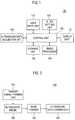
- FIG. 2is a block diagram showing an illustrative embodiment of the ultrasound data acquisition unit 140.
- the ultrasound data acquisition unit 140includes a transmit signal forming unit 210, a ultrasound probe 220 including a plurality of transducer elements, a beam former 230 and a ultrasound data forming unit 240.
- the transmit signal forming unit 210is operable to form a transmit signal to be applied to each of the transducer elements of the ultrasound probe 220.
- the positions and focusing points of the transducer elementsare considered in forming the transmit signal.
- the transmit signalincludes a first transmit signal for acquiring the CM mode image and a second transmit signal for acquiring the BM mode image.
- the ultrasound probe 220operates to convert the transmit signal provided by the transmit signal forming unit 210 into an ultrasound signal and transmit it to the target object.
- the ultrasound probe 220further operates to receive the ultrasound echo signal reflected from the target object and form a receive signal.
- the ultrasound probe 220when the first transmit signal is provided by the transmit signal forming unit 210, the ultrasound probe 220 operates to convert the first transmit signal into an ultrasound signal, transmit it to the target object, receive the ultrasound echo signal reflected from the target object and form a first receive signal.
- the ultrasound probe 220when the second transmit signal is provided by the transmit signal forming unit 210, the ultrasound probe 220 operates to convert the second transmit signal into an ultrasound signal, transmit it to the target object, receive the ultrasound echo signal reflected from the target object and form a second receive signal.
- the beam former 230is configured to form a first digital signal through analog-to-digital conversion of the first receive signal when the first receive signal is provided by the ultrasound probe 220.
- the beam former 230performs receive-focusing upon the first digital signal in consideration of the positions and focusing points of the transducer elements of the ultrasound probe 220, and forms a first receive-focused signal thereby.
- the beam former 230forms a second digital signal through analog-to-digital conversion of the second receive signal when the second receive signal is provided by the ultrasound probe 220.
- the beam former 230performs receive-focusing upon the second digital signal in consideration of the positions and focusing points of the transducer elements of the ultrasound probe 220, and forms a second receive-focused signal thereby.
- the ultrasound data forming unit 240is configured to form the first piece of ultrasound data using the first receive-focused signal when the first receive-focused signal is provided by the beam former 230. In one embodiment, the ultrasound data forming unit 240 is configured to form the second piece of ultrasound data using the second receive-focused signal when the second receive-focused signal is provided by the beam former 230. Further, the ultrasound data forming unit 240 performs various signal processing (e.g., gain adjustment, filtering) to the first and second receive-focused signal for forming the ultrasound data.
- various signal processinge.g., gain adjustment, filtering
- the storage unit 150is configured to store the first and second pieces of ultrasound data provided by the ultrasound data acquisition unit 140 according to the control unit 130.
- the storage unit 150is configured to store the first pieces of ultrasound data (CM) and the second pieces of ultrasound data (BM) in the order of being provided from the ultrasound data acquisition unit 140 according to the control unit 130, as illustrated in FIG. 7 .
- the storage unit 150is configured to store the first pieces of ultrasound data (CM) and the second pieces of ultrasound data (BM) in the order of being provided from the ultrasound data acquisition unit 140 according to the control unit 130, as illustrated in FIG. 8 .
- the storage unit 150has been explained as storing the first pieces of ultrasound data and the second pieces of ultrasound data, the present invention is certainly not limited thereto.
- the storage unit 150includes a first storage unit (not shown) for storing the first pieces of ultrasound data and a second storage unit (not shown) for storing the second pieces of ultrasound data.
- the image processor 160is operable to extract the first pieces of ultrasound data and the second pieces of ultrasound data in consideration of the sweep speed, the average number, the ultrasound data acquisition period and the ultrasound data acquisition time according to the control unit 130.
- the image processor 160further operates to form the CM mode image and the BM mode image based on the extracted first and second pieces of ultrasound data.
- FIG. 3is a block diagram showing an illustrative embodiment of the image processor 160.
- the image processor 160includes a determination unit 310, an extraction unit 320, a CM mode image forming unit 330 and a BM mode image forming unit 340.
- the determination unit 310is configured to form a determination result using the sweep speed, the average number, the ultrasound data acquisition period and the ultrasound data acquisition time.
- the determination unit 310is configured to form first determination information if the ultrasound data acquisition time, which is the aggregate time (T 1 + T 2 ) calculated by adding the first time to the second time, is less than the ultrasound data acquisition period (T CM ), as illustrated in FIG. 5 .
- the determination unit 310is configured to form second determination information if the aggregate time (T 1 + T 2 ) calculated by adding the first time to the second time is equal to or more than the ultrasound data acquisition period (T CM ), as illustrated in FIG. 6 .
- the extraction unit 320is configured to extract the first pieces of ultrasound data and the second pieces of ultrasound data based on the sweep speed when the first determination information is provided by the determination unit 310.
- the extraction unit 320is configured to extract a predetermined number (e.g., 12) of the first pieces of ultrasound data (CM 18 -CM 7 ) starting at the first piece of ultrasound data (CM 18 ), which is lastly stored during the sweep period, from the storage unit 150, as illustrated in FIG. 7 .
- the extraction unit 320further operates to extract the second piece of ultrasound data (BM 18 ), which is lastly stored during the sweep period, from the storage unit 150.
- the extraction unit 320is configured to extract a predetermined number (e.g., 12) of the first pieces of ultrasound data (CM 18 -CM 7 ) starting at the first piece of ultrasound data (CM 18 ), which is lastly stored during the sweep period, from the storage unit 150, as illustrated in FIG. 7 .
- the extraction unit 320further operates to extract a predetermined number (e.g., 12) of the second pieces of ultrasound data (BM 18 -BM 7 ) starting at the second piece of ultrasound data (BM 18 ), which is lastly stored during the sweep period, from the storage unit 150, as illustrated in FIG. 7 .
- the extraction unit 320is configured to extract a predetermined number of the first pieces of ultrasound data and the second pieces of ultrasound data accumulated during the sweep period from the storage unit 150 when the second determination information is provided by the determination unit 310.
- the extraction unit 320is configured to extract a predetermined number (e.g., 12) of the ultrasound data (i.e., ten of the first pieces of ultrasound data (CM 16 -CM 7 ) and two of the second pieces of ultrasound data (BM 2 , BM 1 ) starting at the second piece of ultrasound data (BM 2 ), which is lastly stored during the sweep period, from the storage unit 150, as illustrated in FIG. 8 .
- the CM mode image forming unit 330operates to form the CM mode image based on the first pieces of ultrasound data extracted by the extraction unit 320.
- the CM mode image forming unit 330operates to calculate mean power, mean velocity and variance corresponding to the CM mode image based on the first pieces of ultrasound data (CM 18 -CM 7 ) and forms the CM mode image using the calculated mean power (P), mean velocity (v) and variance ( ⁇ 2 ).
- mean power, mean velocity and varianceare calculated according to the following equation (1).
- R[0]denotes 0 th order autocorrelation
- R[1]denotes 1 th order autocorrelation
- Ndenotes the average number equal to or greater than 2
- x[n]denotes the input signal
- Im()denotes an imaginary part of a complex number
- Re()denotes a real part of the complex number.
- the CM mode image forming unit 330operates to calculate mean power, mean velocity and variance corresponding to the CM mode image using the first pieces of ultrasound data (CM 16 -CM 7 ), and forms the CM mode image using the calculated mean power, mean velocity and variance.
- mean power (P), mean velocity (v) and variance ( ⁇ 2 )are calculated according to the following equation (2).
- the CM mode image forming unit 330when the first pieces of ultrasound data (CM 16 -CM 7 ) extracted by the extraction unit 320 are provided, the CM mode image forming unit 330 operates to obtain third pieces of ultrasound data (CM 8 ' and CM 16 '), which were not provided at the sweep speed, with the use of interpolation of the first pieces of ultrasound data (CM 16 -CM 7 ) as illustrated in FIG. 9 .
- the CM mode image forming unit 330further operates to calculate an error comparing the first pieces of ultrasound data (CM 16 -CM 7 ) extracted by the extraction unit 320 with the third pieces of ultrasound data (CM 8 ' and CM 16 ') obtained by using the interpolation.
- the CM mode image forming unit 330operates to calculate mean power, mean velocity and variance using the first pieces of ultrasound data (CM 16 -CM 7 ) extracted by the extraction unit 320 and the third pieces of ultrasound data (CM 8 ' and CM 16 ') obtained by using the interpolation, and forms the CM mode image using the calculated mean power, mean velocity and variance. Assuming that the number of third pieces of ultrasound data obtained by using the interpolation is K, the third pieces of ultrasound data obtained by using the interpolation are located at M, M+1, and the total number of the first and third pieces of ultrasound data is N.
- mean power (P total ), mean velocity (v total ) and variance ( ⁇ 2 total )may be calculated according to the following equation (3).
- P IP , v IP and ⁇ 2 IPrespectively represent mean power, mean velocity and variance, which are calculated from the third pieces of ultrasound data (CM 8 ' and CM 16 ') obtained by using the interpolation.
- the CM mode image forming unit 330operates to calculate mean power, mean velocity and variance only using the first pieces of ultrasound data (CM 16 -CM 7 ) extracted by the extraction unit 320, and forms the CM mode image using the calculated mean power, mean velocity and variance.
- the BM mode image forming unit 340operates to form a BM mode image based on the second pieces of ultrasound data extracted by the extraction unit 320.
- the BM mode image forming unit 340operates to form the BM mode image based on the second piece of ultrasound data (BM 18 ).
- the BM mode image forming unit 340operates to form the BM mode image through performing, for example, line average to the second pieces of ultrasound data (BM 18 -BM 7 ).
- the BM mode image forming unit 340operates to form the BM mode image through performing, for example, line average to the second pieces of ultrasound data (BM 1 and BM 2 ).
- the display unit 170operates to display the CM mode image and the BM mode image formed at the image processor 160 according to the control unit 130.
- the display unitfurther operates to display the B mode image 410, the color doppler mode image 420 and the M line 440, as illustrated in FIG. 4 .
- the display unit 170includes a liquid crystal display (LCD), a cathode ray tube (CRT) or any other device capable of displaying an image.
- LCDliquid crystal display
- CRTcathode ray tube
Landscapes
- Engineering & Computer Science (AREA)
- Physics & Mathematics (AREA)
- Radar, Positioning & Navigation (AREA)
- Remote Sensing (AREA)
- Computer Networks & Wireless Communication (AREA)
- General Physics & Mathematics (AREA)
- Health & Medical Sciences (AREA)
- Life Sciences & Earth Sciences (AREA)
- Acoustics & Sound (AREA)
- Nuclear Medicine, Radiotherapy & Molecular Imaging (AREA)
- Molecular Biology (AREA)
- Pathology (AREA)
- Radiology & Medical Imaging (AREA)
- Biomedical Technology (AREA)
- Heart & Thoracic Surgery (AREA)
- Medical Informatics (AREA)
- Biophysics (AREA)
- Surgery (AREA)
- Animal Behavior & Ethology (AREA)
- General Health & Medical Sciences (AREA)
- Public Health (AREA)
- Veterinary Medicine (AREA)
- Ultra Sonic Daignosis Equipment (AREA)
Description
- The present disclosure relates to ultrasound systems, and more particularly to an ultrasound system and a method of providing a color M mode image and a brightness M mode image corresponding to an M line set on a color Doppler mode image and a B mode (brightness mode) image.
- An ultrasound system has been extensively used for acquiring internal information of a target object due to its non-invasive and non-destructive nature. Since the ultrasound system may provide a high resolution image in real-time without any surgical treatment, it has proven to be very helpful in the medical profession.
- Generally, the ultrasound system provides B mode (brightness mode) that shows a reflection coefficient of a ultrasound signal reflected from a target object in a 2-dimensional image, doppler mode showing an image of a moving target object using doppler effect, motion mode (M mode) showing a change of biometric information (e.g., brightness information) over time of a target object in a particular part of a B mode image, and elastic mode showing a difference of reaction between a target object with and without compression in an image.
- Also, the ultrasound system sets an M line on the B mode image and the color doppler mode image, and provides the color M mode image and the brightness M mode image corresponding to the M line. The color M mode image may show how the blood flow changes over time on the M line. Typically, the M mode acquires ultrasound data within a particular time interval (i.e., sweep period) and displays an M mode image formed from the acquired ultrasound data. The sweep speed of the color M mode is commonly used in a range of 60 to 360Hz, which is not sufficient from the point of the time resolution. In the brightness M mode, assuming that the velocity of sound is 1540m/s and the depth is 15cm, the time required to acquire the ultrasound data corresponding to one scan line is very short, i.e., approximately 200µs, when the pulse repetition frequency (PRF) of the ultrasound is 5 KHz . Thus, the problem of the time resolution does not occur. In other words, the brightness M mode has no problem in acquiring the ultrasound data corresponding to one scan line. The color M mode acquires a plurality of ultrasound data on one scan line by repeatedly transmitting and receiving an ultrasound signal as many times as an average number of the data acquisition (an ensemble number) in the same direction. An ultrasound data acquisition period for acquiring ultrasound data of color M mode is inversely proportional to the sweep speed. For example, if the ultrasound data acquisition frequency (the PRF for radiating the ultrasound) is 2kHz and the average number of the data acquisition is 12, then the time for forming the color M mode image according to one scan line is 6000µs = 500µs (the ultrasound data acquisition frequency (2kHz)) x 12 (the average number). In such a case, the sweep speed should be less than 160Hz (1/6000µs). With this low speed, it is difficult to provide continuous color M mode. Also, as the average number is reduced to increase the sweep speed, the ultrasound data for forming the color M mode image should be reduced. This also degrades the quality of the color M mode image.
- The
EP 1 498 746 A1 - In the
US 2003/0045795 A1 a method is provided to simultaneously acquire two ultrasound images. A first set of ultrasound pulses are transmitted at a first frame rate utilizing a first mode of operation. The echoes from the first set of ultrasound pulses are received. A second set of ultrasound pulses are transmitted at a second frame rate utilizing a second mode of operation. The first and second frame rates are different. The first set of ultrasound pulses defines an entire image, while the second set of ultrasound pulses defines a partial image. The echoes from the second set of ultrasound pulses are received, and the echoes from the first and second sets of ultrasound pulses are displayed as a single image. - In the
US 4 817 617 a diagnostic imaging apparatus is disclosed in which an ultrasonic wave transmit/receive apparatus is used in common for both 2-dimensional B-mode imaging and for measurement of pulsed Doppler signals, by time sharing operation. The good real time characteristics of 2-dimensional B-mode imaging are retained, together with a sufficiently high data rate for pulsed Doppler measurement, through use of simple means for performing interpolation in the Doppler signals Ultrasonic wave transmit/receive means repetitively execute combinations of ultrasonic wave transmit/receive sequences, each combination consisting of a plurality of pulsed Doppler mode ultrasonic wave transmit/receive sequences and a single 2-dimensional B-mode imaging ultrasonic wave transmit/receive sequence. Demodulator means demodulate the Doppler signals, based on the received signals that are acquired during the pulsed Doppler mode ultrasonic wave transmit/receive sequences. Sampling means perform range gate sampling of the demodulated Doppler signals, and interpolation means interpolate sampling values into the Doppler signal to replace sampling values which are lost during execution of the 2-dimensional B-mode imagaing ultrasonic wave transmit/receive sequences. Doppler signal processing means perform processing of the sampling signals following interpolation. 2-dimensional B-mode imaging means process the received signal that is acquired by the 2-dimensional B-mode imaging sequences. - Embodiments of an ultrasound system and a method adapted to provide a color M mode image and a brightness M mode image with high quality based on an average number (an ensemble number) and a sweep period for acquiring the color M mode image are disclosed herein, the ultrasound system and the method being specified in
claims - FIG. 1
- is a block diagram showing an illustrative embodiment of an ultrasound system.
- FIG. 2
- is a block diagram showing an illustrative embodiment of an ultrasound data acquisition unit.
- FIG. 3
- is a block diagram showing an illustrative embodiment of an image processor.
- FIG. 4
- shows an example of an M line set on a B mode image and color doppler mode image.
- FIGS. 5 and FIG. 6
- show an example of acquiring first pieces of ultrasound data and second pieces of ultrasound data.
- FIGS.7 and 8
- show an example of the first pieces of ultrasound data and the second pieces of ultrasound data stored in a storage unit.
- FIG. 9
- shows an example of third pieces of ultrasound data obtained through interpolation of the first pieces of ultrasound data.
- A detailed description may be provided with reference to the accompanying drawings.
FIG. 1 is a block diagram showing an illustrative embodiment of anultrasound system 100. Theultrasound system 100 comprises auser input unit 110, an Mline setting unit 120, acontrol unit 130, an ultrasounddata acquisition unit 140, astorage unit 150, animage processor 160 and adisplay unit 170. - The
user input unit 110 is implemented as a control panel, a mouse, a keyboard, etc., to allow a user to input M line setting information. The M line setting information comprises location information of theM line 440 set on a B mode (brightness mode)image 410 and a colordoppler mode image 420, as illustrated inFIG. 4 . Thereference number 430 represents an area of interest for acquiring the colordoppler mode image 420 inFIG. 4 . - The M
line setting unit 120 is configured to set theM line 440 on the B mode (brightness mode)image 410 and the colordoppler mode image 420 according to the M line setting information provided by theuser input unit 110, as illustrated inFIG. 4 . Although in the aforementioned embodiment, the Mline setting unit 120 has been explained as setting the M line on the B mode image and the color doppler mode image according to the M line setting information provided by theuser input unit 110, the present invention is certainly not limited thereto. In another embodiment, the Mline setting unit 120 may be configured to set the M line on the B mode image and the color doppler mode image according to a predetermined M line setting information. Thecontrol unit 130 is operable to control acquisition of an ultrasound data according to a sweep speed, a sweep period, an average number, an ultrasound data acquisition period and an ultrasound data acquisition time. The sweep period is a time period of displaying an ultrasound image and the sweep speed is the end point of every sweep period. The ultrasound data acquisition period is a time period of providing a first piece of ultrasound data. The ultrasound data acquisition period is equal to the sweep period divided by the average number. The first piece of ultrasound data includes ultrasound data for acquiring a color motion mode (CM mode) image corresponding to the M line. The ultrasound data acquisition time includes a time period expected for providing the first piece of ultrasound data (hereinafter referred to as first time) and a time period expected for providing a second piece of ultrasound data (hereinafter referred to as second time). The second piece of ultrasound data includes ultrasound data for acquiring a brightness M mode (BM mode) image corresponding to the M line. Thecontrol unit 130 calculates an aggregate time (T1 + T2) by adding the first time (T1) to the second time (T2), as illustrated inFIG 5 and FIG. 6 . Thecontrol unit 130 compares the aggregate time (T1 + T2) with the ultrasound data acquisition period (TCM). If the aggregate time (T1 + T2) is less than the ultrasound data acquisition period (TCM), then thecontrol unit 130 controls the first piece of ultrasound data (CM) and the second piece of ultrasound data (BM) to be provided alternately, as illustrated inFIG. 5 . If the aggregate time (T1 + T2) is equal to or greater than the ultrasound data acquisition period (TCM), then thecontrol unit 130 may control the first pieces of ultrasound data (CM) to be provided by the average number and then the second piece of ultrasound data (BM) to be provided once at the sweep speed (SP), as illustrated inFIG. 6 . - Further, the
control unit 130 may operate to control the setting of the M line and storage of the ultrasound data. Additionally, thecontrol unit 130 operates to control formation and display of the CM mode image and the BM mode image according to the ultrasound acquisition period and the ultrasound acquisition time. - The
ultrasound acquisition unit 140 is operable to transmit an ultrasound signal to a target object, receive the ultrasound signal reflected from the target object (i.e., ultrasound echo signal), and provide the ultrasound data according to thecontrol unit 130. FIG. 2 is a block diagram showing an illustrative embodiment of the ultrasounddata acquisition unit 140. The ultrasounddata acquisition unit 140 includes a transmitsignal forming unit 210, aultrasound probe 220 including a plurality of transducer elements, a beam former 230 and a ultrasounddata forming unit 240.- The transmit
signal forming unit 210 is operable to form a transmit signal to be applied to each of the transducer elements of theultrasound probe 220. By way of a non-limiting example, the positions and focusing points of the transducer elements are considered in forming the transmit signal. In one embodiment, the transmit signal includes a first transmit signal for acquiring the CM mode image and a second transmit signal for acquiring the BM mode image. - The
ultrasound probe 220 operates to convert the transmit signal provided by the transmitsignal forming unit 210 into an ultrasound signal and transmit it to the target object. Theultrasound probe 220 further operates to receive the ultrasound echo signal reflected from the target object and form a receive signal. In one embodiment, when the first transmit signal is provided by the transmitsignal forming unit 210, theultrasound probe 220 operates to convert the first transmit signal into an ultrasound signal, transmit it to the target object, receive the ultrasound echo signal reflected from the target object and form a first receive signal. In one embodiment, when the second transmit signal is provided by the transmitsignal forming unit 210, theultrasound probe 220 operates to convert the second transmit signal into an ultrasound signal, transmit it to the target object, receive the ultrasound echo signal reflected from the target object and form a second receive signal. - In one embodiment, the beam former 230 is configured to form a first digital signal through analog-to-digital conversion of the first receive signal when the first receive signal is provided by the
ultrasound probe 220. The beam former 230 performs receive-focusing upon the first digital signal in consideration of the positions and focusing points of the transducer elements of theultrasound probe 220, and forms a first receive-focused signal thereby. In one embodiment, the beam former 230 forms a second digital signal through analog-to-digital conversion of the second receive signal when the second receive signal is provided by theultrasound probe 220. The beam former 230 performs receive-focusing upon the second digital signal in consideration of the positions and focusing points of the transducer elements of theultrasound probe 220, and forms a second receive-focused signal thereby. - In one embodiment, the ultrasound
data forming unit 240 is configured to form the first piece of ultrasound data using the first receive-focused signal when the first receive-focused signal is provided by the beam former 230. In one embodiment, the ultrasounddata forming unit 240 is configured to form the second piece of ultrasound data using the second receive-focused signal when the second receive-focused signal is provided by the beam former 230. Further, the ultrasounddata forming unit 240 performs various signal processing (e.g., gain adjustment, filtering) to the first and second receive-focused signal for forming the ultrasound data. - Referring back to
FIG. 1 , thestorage unit 150 is configured to store the first and second pieces of ultrasound data provided by the ultrasounddata acquisition unit 140 according to thecontrol unit 130. In one embodiment, thestorage unit 150 is configured to store the first pieces of ultrasound data (CM) and the second pieces of ultrasound data (BM) in the order of being provided from the ultrasounddata acquisition unit 140 according to thecontrol unit 130, as illustrated inFIG. 7 . In another embodiment, thestorage unit 150 is configured to store the first pieces of ultrasound data (CM) and the second pieces of ultrasound data (BM) in the order of being provided from the ultrasounddata acquisition unit 140 according to thecontrol unit 130, as illustrated inFIG. 8 . - Although in the aforementioned embodiment, the
storage unit 150 has been explained as storing the first pieces of ultrasound data and the second pieces of ultrasound data, the present invention is certainly not limited thereto. In another embodiment, thestorage unit 150 includes a first storage unit (not shown) for storing the first pieces of ultrasound data and a second storage unit (not shown) for storing the second pieces of ultrasound data. - The
image processor 160 is operable to extract the first pieces of ultrasound data and the second pieces of ultrasound data in consideration of the sweep speed, the average number, the ultrasound data acquisition period and the ultrasound data acquisition time according to thecontrol unit 130. Theimage processor 160 further operates to form the CM mode image and the BM mode image based on the extracted first and second pieces of ultrasound data. FIG. 3 is a block diagram showing an illustrative embodiment of theimage processor 160. Theimage processor 160 includes adetermination unit 310, anextraction unit 320, a CM modeimage forming unit 330 and a BM modeimage forming unit 340.- The
determination unit 310 is configured to form a determination result using the sweep speed, the average number, the ultrasound data acquisition period and the ultrasound data acquisition time. Thedetermination unit 310 is configured to form first determination information if the ultrasound data acquisition time, which is the aggregate time (T1 + T2) calculated by adding the first time to the second time, is less than the ultrasound data acquisition period (TCM), as illustrated inFIG. 5 . In one embodiment, thedetermination unit 310 is configured to form second determination information if the aggregate time (T1 + T2) calculated by adding the first time to the second time is equal to or more than the ultrasound data acquisition period (TCM), as illustrated inFIG. 6 . - The
extraction unit 320 is configured to extract the first pieces of ultrasound data and the second pieces of ultrasound data based on the sweep speed when the first determination information is provided by thedetermination unit 310. In one embodiment, theextraction unit 320 is configured to extract a predetermined number (e.g., 12) of the first pieces of ultrasound data (CM18-CM7) starting at the first piece of ultrasound data (CM18), which is lastly stored during the sweep period, from thestorage unit 150, as illustrated inFIG. 7 . Theextraction unit 320 further operates to extract the second piece of ultrasound data (BM18), which is lastly stored during the sweep period, from thestorage unit 150. In another embodiment, theextraction unit 320 is configured to extract a predetermined number (e.g., 12) of the first pieces of ultrasound data (CM18-CM7) starting at the first piece of ultrasound data (CM18), which is lastly stored during the sweep period, from thestorage unit 150, as illustrated inFIG. 7 . Theextraction unit 320 further operates to extract a predetermined number (e.g., 12) of the second pieces of ultrasound data (BM18-BM7) starting at the second piece of ultrasound data (BM18), which is lastly stored during the sweep period, from thestorage unit 150, as illustrated inFIG. 7 . - The
extraction unit 320 is configured to extract a predetermined number of the first pieces of ultrasound data and the second pieces of ultrasound data accumulated during the sweep period from thestorage unit 150 when the second determination information is provided by thedetermination unit 310. In one embodiment, theextraction unit 320 is configured to extract a predetermined number (e.g., 12) of the ultrasound data (i.e., ten of the first pieces of ultrasound data (CM16-CM7) and two of the second pieces of ultrasound data (BM2, BM1) starting at the second piece of ultrasound data (BM2), which is lastly stored during the sweep period, from thestorage unit 150, as illustrated inFIG. 8 . - The CM mode
image forming unit 330 operates to form the CM mode image based on the first pieces of ultrasound data extracted by theextraction unit 320. In one embodiment, when the first pieces of ultrasound data (CM18-CM7) extracted by theextraction unit 320 are provided, the CM modeimage forming unit 330 operates to calculate mean power, mean velocity and variance corresponding to the CM mode image based on the first pieces of ultrasound data (CM18-CM7) and forms the CM mode image using the calculated mean power (P), mean velocity (v) and variance (σ2). By way of a non-limiting example, mean power, mean velocity and variance are calculated according to the following equation (1).
- In
equation 1, R[0] denotes 0th order autocorrelation, R[1] denotes 1th order autocorrelation, "N" denotes the average number equal to or greater than 2, x[n] denotes the input signal, Im() denotes an imaginary part of a complex number, and Re() denotes a real part of the complex number. - In another embodiment, when the first pieces of ultrasound data (CM16-CM7) extracted by the
extraction unit 320 are provided, the CM modeimage forming unit 330 operates to calculate mean power, mean velocity and variance corresponding to the CM mode image using the first pieces of ultrasound data (CM16-CM7), and forms the CM mode image using the calculated mean power, mean velocity and variance. By way of a non-limiting example, mean power (P), mean velocity (v) and variance (σ2) are calculated according to the following equation (2).
- In yet another embodiment, when the first pieces of ultrasound data (CM16-CM7) extracted by the
extraction unit 320 are provided, the CM modeimage forming unit 330 operates to obtain third pieces of ultrasound data (CM8' and CM16'), which were not provided at the sweep speed, with the use of interpolation of the first pieces of ultrasound data (CM16-CM7) as illustrated inFIG. 9 . The CM modeimage forming unit 330 further operates to calculate an error comparing the first pieces of ultrasound data (CM16-CM7) extracted by theextraction unit 320 with the third pieces of ultrasound data (CM8' and CM16') obtained by using the interpolation. If the calculated error is less than a predetermined threshold, then the CM modeimage forming unit 330 operates to calculate mean power, mean velocity and variance using the first pieces of ultrasound data (CM16-CM7) extracted by theextraction unit 320 and the third pieces of ultrasound data (CM8' and CM16') obtained by using the interpolation, and forms the CM mode image using the calculated mean power, mean velocity and variance. Assuming that the number of third pieces of ultrasound data obtained by using the interpolation is K, the third pieces of ultrasound data obtained by using the interpolation are located at M, M+1, and the total number of the first and third pieces of ultrasound data is N. Under the above conditions, mean power (Ptotal), mean velocity (vtotal) and variance (σ2total) may be calculated according to the following equation (3).
- In equation (3), PIP, vIP and σ2IP respectively represent mean power, mean velocity and variance, which are calculated from the third pieces of ultrasound data (CM8' and CM16') obtained by using the interpolation.
- If the calculated error is more than the predetermined threshold, then the CM mode
image forming unit 330 operates to calculate mean power, mean velocity and variance only using the first pieces of ultrasound data (CM16-CM7) extracted by theextraction unit 320, and forms the CM mode image using the calculated mean power, mean velocity and variance. - The BM mode
image forming unit 340 operates to form a BM mode image based on the second pieces of ultrasound data extracted by theextraction unit 320. In oneextraction unit 320 is provided, the BM modeimage forming unit 340 operates to form the BM mode image based on the second piece of ultrasound data (BM18). In another embodiment, when the second pieces of ultrasound data (BM18-BM7) extracted by theextraction unit 320 are provided, the BM modeimage forming unit 340 operates to form the BM mode image through performing, for example, line average to the second pieces of ultrasound data (BM18-BM7). In yet another embodiment, when the second pieces of ultrasound data (BM1 and BM2) extracted by theextraction unit 320 are provided, the BM modeimage forming unit 340 operates to form the BM mode image through performing, for example, line average to the second pieces of ultrasound data (BM1 and BM2). - Referring back to
FIG. 1 , thedisplay unit 170 operates to display the CM mode image and the BM mode image formed at theimage processor 160 according to thecontrol unit 130. The display unit further operates to display theB mode image 410, the colordoppler mode image 420 and theM line 440, as illustrated inFIG. 4 . In one embodiment, thedisplay unit 170 includes a liquid crystal display (LCD), a cathode ray tube (CRT) or any other device capable of displaying an image.


Claims (13)
- An ultrasound system (100), comprising:an ultrasound data acquisition unit (140) configured to perform a first operation for providing first ultrasound data for forming a color M mode image and a second operation for providing second ultrasound data for forming a brightness M mode image;a control unit (130) configured to control the ultrasound data acquisition unit (140) to perform the first operation by a number of times equal to an ensemble number and the second operation one or more times according to an acquisition pattern within a sweep period to respectively accumulate the first ultrasound data and the second ultrasound data provided from the ultrasound data acquisition unit; andan image processor (160) configured to form the color M mode image based on the accumulated first ultrasound data and to form the brightness M mode image based on the accumulated second ultrasound data,characterized in thatthe control unit (130) is further configured to calculate a time period expected for the ultrasound data acquisition unit (140) to perform the first and second operations once and to determine the acquisition pattern defining an order of performing the first and second operations based on the calculated time period, the sweep period, and the ensemble number, wherein the acquisition pattern is a pattern in which the first operation and the second operation are alternate, if the calculated time period is less than the sweep period divided by the ensemble number.
- The ultrasound system (100) of Claim 1, wherein the ensemble number is programmable.
- The ultrasound system (100) of Claim 1, wherein the image processor (160) is configured to form the brightness M mode image based on the second ultrasound data lastly provided by the ultrasound data acquisition unit (140) during the sweep period.
- The ultrasound system (100) of Claim 1, wherein the image processor (160) is configured to form the brightness M mode image based on the second ultrasound data provided by the ultrasound data acquisition unit (140) during the sweep period.
- The ultrasound system (100) of Claim 1, wherein the acquisition pattern is a pattern in which the first operation is performed by the number of times and then the second operation is performed once, if a time period expected for the ultrasound data acquisition unit (140) to perform the first and second operations once respectively is equal to or more than the sweep period divided by the ensemble number.
- The ultrasound system (100) of Claim 5, wherein the image processor (160) is configured to form the color M mode image based on the first ultrasound data provided by the ultrasound data acquisition unit during the sweep period and to form the brightness M mode image based on the second ultrasound data provided by the ultrasound data acquisition unit (140) during the sweep period.
- The ultrasound system (100) of Claim 5, wherein the image processor (160) is configured to obtain a third ultrasound data by using interpolation of the first ultrasound data provided by the ultrasound data acquisition unit (140) during the sweep period and form the color M mode image based on the first ultrasound data and the third ultrasound data.
- A method of providing a color M mode image and a brightness M mode image, comprising:a) performing at an ultrasound data acquisition unit (140) a first operation for providing first ultrasound data for forming a color M mode image and a second operation for providing second ultrasound data for forming a brightness M mode image;b) controlling the ultrasound data acquisition unit (140) to perform the first operation a number of times equal to an ensemble number and the second operation one or more times according to an acquisition pattern within a sweep period to respectively accumulate the first ultrasound data and the second ultrasound data provided from the ultrasound data acquisition unit;c) forming the color M mode image based on the first ultrasound data; andd) forming the brightness M mode image based on the second ultrasound data, the method beingcharacterized by the additional steps:e) calculating a time period expected for the ultrasound data acquisition unit (140) to perform the first and second operations once andf) determining the acquisition pattern defining an order of performing the first and second operations based on the calculated time period, the sweep period, and the ensemble number, wherein the acquisition pattern is a pattern in which the first operation and the second operation alternate, if the calculated time period is less than the sweep period divided by the ensemble number.
- The method of Claim 8, wherein forming the brightness M mode image further comprises:forming the brightness M mode image based on the second ultrasound data lastly provided by the ultrasound data acquisition unit during the sweep period.
- The method of Claim 8, wherein forming the brightness M mode image further comprises:forming the brightness M mode image based on the second ultrasound data provided by the ultrasound data acquisition unit during the sweep period.
- The method of Claim 8, wherein the acquisition pattern is a pattern in which the first operation is performed by the number of times and then the second operation is performed once, if the calculated time period is equal to or more than the sweep period divided by the ensemble number.
- The method of Claim 11, wherein forming the color M mode image further comprises:forming the color M mode image based on the first ultrasound data provided by the ultrasound data acquisition unit during the sweep period; andwherein forming the brightness M mode image further comprises:forming the brightness M mode image based on the second ultrasound data provided by the ultrasound data acquisition unit during the sweep period.
- The method of Claim 11, wherein forming the color M mode image further comprises:obtaining a third ultrasound data by using interpolation of the first ultrasound data provided by the ultrasound data acquisition unit during the sweep period; andforming the color M mode image based on the first ultrasound data and the third ultrasound data.
Applications Claiming Priority (1)
| Application Number | Priority Date | Filing Date | Title |
|---|---|---|---|
| KR20090029678 | 2009-04-07 |
Publications (3)
| Publication Number | Publication Date |
|---|---|
| EP2238912A2 EP2238912A2 (en) | 2010-10-13 |
| EP2238912A3 EP2238912A3 (en) | 2012-11-28 |
| EP2238912B1true EP2238912B1 (en) | 2016-01-27 |
Family
ID=42340374
Family Applications (1)
| Application Number | Title | Priority Date | Filing Date |
|---|---|---|---|
| EP10157867.2AActiveEP2238912B1 (en) | 2009-04-07 | 2010-03-26 | Ultrasound system and method of providing color M mode image and brightness M mode image |
Country Status (4)
| Country | Link |
|---|---|
| US (1) | US8491478B2 (en) |
| EP (1) | EP2238912B1 (en) |
| JP (1) | JP5650430B2 (en) |
| KR (1) | KR101117854B1 (en) |
Families Citing this family (1)
| Publication number | Priority date | Publication date | Assignee | Title |
|---|---|---|---|---|
| KR101386099B1 (en)* | 2011-12-27 | 2014-04-16 | 삼성메디슨 주식회사 | Ultrasound system and method for providing vector motion mode image |
Family Cites Families (17)
| Publication number | Priority date | Publication date | Assignee | Title |
|---|---|---|---|---|
| JPS6125534A (en)* | 1984-07-16 | 1986-02-04 | 横河メディカルシステム株式会社 | Image diagnostic apparatus |
| JPH0475645A (en)* | 1990-07-19 | 1992-03-10 | Toshiba Corp | Ultrasound diagnostic equipment |
| JP3386853B2 (en)* | 1993-07-23 | 2003-03-17 | フクダ電子株式会社 | Ultrasound diagnostic equipment |
| US5800356A (en)* | 1997-05-29 | 1998-09-01 | Advanced Technology Laboratories, Inc. | Ultrasonic diagnostic imaging system with doppler assisted tracking of tissue motion |
| US5916168A (en)* | 1997-05-29 | 1999-06-29 | Advanced Technology Laboratories, Inc. | Three dimensional M-mode ultrasonic diagnostic imaging system |
| US6050944A (en)* | 1997-06-17 | 2000-04-18 | Acuson Corporation | Method and apparatus for frequency control of an ultrasound system |
| US6537217B1 (en)* | 2001-08-24 | 2003-03-25 | Ge Medical Systems Global Technology Company, Llc | Method and apparatus for improved spatial and temporal resolution in ultrasound imaging |
| JP2004166897A (en) | 2002-11-19 | 2004-06-17 | Aloka Co Ltd | Ultrasonic diagnostic equipment |
| EP1498746B1 (en)* | 2003-07-09 | 2013-12-11 | Panasonic Corporation | Ultrasonic diagnostic apparatus and tomographic image processing apparatus |
| JP4520235B2 (en)* | 2003-07-09 | 2010-08-04 | パナソニック株式会社 | Ultrasonic diagnostic apparatus and ultrasonic diagnostic method |
| CN101036162A (en) | 2004-10-07 | 2007-09-12 | 皇家飞利浦电子股份有限公司 | Method and system for maintaining consistent anatomic vieuws in displayed image data |
| JP4653454B2 (en)* | 2004-10-22 | 2011-03-16 | 株式会社東芝 | Ultrasonic diagnostic apparatus and control program for the apparatus |
| KR100748178B1 (en) | 2005-01-05 | 2007-08-09 | 주식회사 메디슨 | Ultrasound Diagnostic System and Method for Displaying Arbitrary M-Mode Images |
| CN100525711C (en)* | 2005-08-29 | 2009-08-12 | 深圳迈瑞生物医疗电子股份有限公司 | Anatomy M shape imaging method and apparatus based on sport interpolation |
| US7670293B2 (en)* | 2005-10-17 | 2010-03-02 | General Electric Company | Method and system for scan sequencing in an ultrasound imaging system |
| KR100961854B1 (en) | 2007-03-16 | 2010-06-09 | 주식회사 메디슨 | Ultrasound Diagnostic System and Method for Displaying Doppler Spectrum Images |
| JP2008272033A (en)* | 2007-04-26 | 2008-11-13 | Ge Medical Systems Global Technology Co Llc | Ultrasonic imaging apparatus |
- 2010
- 2010-03-26EPEP10157867.2Apatent/EP2238912B1/enactiveActive
- 2010-04-06JPJP2010088049Apatent/JP5650430B2/ennot_activeExpired - Fee Related
- 2010-04-07USUS12/756,000patent/US8491478B2/enactiveActive
- 2010-04-07KRKR1020100031847Apatent/KR101117854B1/enactiveActive
Also Published As
| Publication number | Publication date |
|---|---|
| US20100256491A1 (en) | 2010-10-07 |
| EP2238912A3 (en) | 2012-11-28 |
| JP5650430B2 (en) | 2015-01-07 |
| US8491478B2 (en) | 2013-07-23 |
| EP2238912A2 (en) | 2010-10-13 |
| JP2010240431A (en) | 2010-10-28 |
| KR20100111633A (en) | 2010-10-15 |
| KR101117854B1 (en) | 2012-03-16 |
Similar Documents
| Publication | Publication Date | Title |
|---|---|---|
| JP4730125B2 (en) | Blood flow image display device | |
| RU2480147C2 (en) | Combined system of photoacoustic and ultrasonic image formation | |
| EP1040323B1 (en) | Cross-sectional color doppler volume flow measurement | |
| US8784318B1 (en) | Aberration correction using channel data in ultrasound imaging system | |
| JP4722283B2 (en) | Method and apparatus for motion visualization in ultrasonic flow imaging using continuous data acquisition | |
| JP3746115B2 (en) | Ultrasonic diagnostic equipment | |
| US20180192989A1 (en) | Methods and systems for ultrasonic imaging | |
| US8602993B2 (en) | Imaging with multiple aperture medical ultrasound and synchronization of add-on systems | |
| JP4627366B2 (en) | Method and apparatus for motion visualization in ultrasonic flow imaging using packet data acquisition | |
| US11346929B2 (en) | Systems and methods for ultrafast ultrasound imaging | |
| US20080177182A1 (en) | Ultrasonic imaging apparatus and method for acquiring ultrasonic image | |
| EP3941358B1 (en) | Three dimensional volume flow quantification and measurement | |
| CN1882849A (en) | Ultrasound imaging system and method having adaptive selection of image frame rate and/or number of echo samples averaged | |
| JP4297699B2 (en) | Method and apparatus for rendering spectral distortion | |
| US20160367223A1 (en) | Ultrasonic diagnostic apparatus and control method | |
| US8348848B1 (en) | Methods and apparatus for ultrasound imaging | |
| EP4061234B1 (en) | Reduction of reverberation artifacts in ultrasound images and associated devices, systems, and methods | |
| US20050203393A1 (en) | Trigger extraction from ultrasound doppler signals | |
| KR20080060625A (en) | Ultrasound diagnosis system and method for obtaining an ultrasound image based on the movement of an object | |
| EP1970011B1 (en) | Ultrasound diagnostic system and method for displaying a doppler spectrum image | |
| EP2077456B1 (en) | Ultrasound system and method of providing ultrasound images | |
| EP2238912B1 (en) | Ultrasound system and method of providing color M mode image and brightness M mode image | |
| JP2005058332A (en) | Ultrasonic diagnostic equipment | |
| JP4426472B2 (en) | Ultrasonic diagnostic equipment | |
| JPH03297454A (en) | Ultrasonic diagnosing device |
Legal Events
| Date | Code | Title | Description |
|---|---|---|---|
| PUAI | Public reference made under article 153(3) epc to a published international application that has entered the european phase | Free format text:ORIGINAL CODE: 0009012 | |
| AK | Designated contracting states | Kind code of ref document:A2 Designated state(s):AT BE BG CH CY CZ DE DK EE ES FI FR GB GR HR HU IE IS IT LI LT LU LV MC MK MT NL NO PL PT RO SE SI SK SM TR | |
| AX | Request for extension of the european patent | Extension state:AL BA ME RS | |
| PUAL | Search report despatched | Free format text:ORIGINAL CODE: 0009013 | |
| AK | Designated contracting states | Kind code of ref document:A3 Designated state(s):AT BE BG CH CY CZ DE DK EE ES FI FR GB GR HR HU IE IS IT LI LT LU LV MC MK MT NL NO PL PT RO SE SI SK SM TR | |
| AX | Request for extension of the european patent | Extension state:AL BA ME RS | |
| RIC1 | Information provided on ipc code assigned before grant | Ipc:G01S 7/52 20060101ALI20121019BHEP Ipc:G01S 15/89 20060101ALI20121019BHEP Ipc:A61B 8/08 20060101AFI20121019BHEP | |
| 17P | Request for examination filed | Effective date:20130523 | |
| RBV | Designated contracting states (corrected) | Designated state(s):AT BE BG CH CY CZ DE DK EE ES FI FR GB GR HR HU IE IS IT LI LT LU LV MC MK MT NL NO PL PT RO SE SI SK SM TR | |
| 17Q | First examination report despatched | Effective date:20130617 | |
| RIC1 | Information provided on ipc code assigned before grant | Ipc:A61B 8/06 20060101ALN20150804BHEP Ipc:G01S 15/89 20060101ALI20150804BHEP Ipc:G01S 7/52 20060101ALI20150804BHEP Ipc:A61B 8/08 20060101AFI20150804BHEP | |
| GRAP | Despatch of communication of intention to grant a patent | Free format text:ORIGINAL CODE: EPIDOSNIGR1 | |
| INTG | Intention to grant announced | Effective date:20150928 | |
| RIN1 | Information on inventor provided before grant (corrected) | Inventor name:KIM, JONG SIK Inventor name:LEE, KWANG JU | |
| GRAS | Grant fee paid | Free format text:ORIGINAL CODE: EPIDOSNIGR3 | |
| RAP1 | Party data changed (applicant data changed or rights of an application transferred) | Owner name:SAMSUNG MEDISON CO., LTD. | |
| GRAA | (expected) grant | Free format text:ORIGINAL CODE: 0009210 | |
| AK | Designated contracting states | Kind code of ref document:B1 Designated state(s):AT BE BG CH CY CZ DE DK EE ES FI FR GB GR HR HU IE IS IT LI LT LU LV MC MK MT NL NO PL PT RO SE SI SK SM TR | |
| REG | Reference to a national code | Ref country code:GB Ref legal event code:FG4D | |
| REG | Reference to a national code | Ref country code:CH Ref legal event code:EP | |
| REG | Reference to a national code | Ref country code:AT Ref legal event code:REF Ref document number:772291 Country of ref document:AT Kind code of ref document:T Effective date:20160215 | |
| REG | Reference to a national code | Ref country code:IE Ref legal event code:FG4D | |
| REG | Reference to a national code | Ref country code:FR Ref legal event code:PLFP Year of fee payment:7 | |
| REG | Reference to a national code | Ref country code:DE Ref legal event code:R096 Ref document number:602010030297 Country of ref document:DE | |
| REG | Reference to a national code | Ref country code:NL Ref legal event code:FP | |
| REG | Reference to a national code | Ref country code:LT Ref legal event code:MG4D | |
| REG | Reference to a national code | Ref country code:AT Ref legal event code:MK05 Ref document number:772291 Country of ref document:AT Kind code of ref document:T Effective date:20160127 | |
| PG25 | Lapsed in a contracting state [announced via postgrant information from national office to epo] | Ref country code:GR Free format text:LAPSE BECAUSE OF FAILURE TO SUBMIT A TRANSLATION OF THE DESCRIPTION OR TO PAY THE FEE WITHIN THE PRESCRIBED TIME-LIMIT Effective date:20160428 Ref country code:FI Free format text:LAPSE BECAUSE OF FAILURE TO SUBMIT A TRANSLATION OF THE DESCRIPTION OR TO PAY THE FEE WITHIN THE PRESCRIBED TIME-LIMIT Effective date:20160127 Ref country code:HR Free format text:LAPSE BECAUSE OF FAILURE TO SUBMIT A TRANSLATION OF THE DESCRIPTION OR TO PAY THE FEE WITHIN THE PRESCRIBED TIME-LIMIT Effective date:20160127 Ref country code:NO Free format text:LAPSE BECAUSE OF FAILURE TO SUBMIT A TRANSLATION OF THE DESCRIPTION OR TO PAY THE FEE WITHIN THE PRESCRIBED TIME-LIMIT Effective date:20160427 Ref country code:ES Free format text:LAPSE BECAUSE OF FAILURE TO SUBMIT A TRANSLATION OF THE DESCRIPTION OR TO PAY THE FEE WITHIN THE PRESCRIBED TIME-LIMIT Effective date:20160127 | |
| PG25 | Lapsed in a contracting state [announced via postgrant information from national office to epo] | Ref country code:LV Free format text:LAPSE BECAUSE OF FAILURE TO SUBMIT A TRANSLATION OF THE DESCRIPTION OR TO PAY THE FEE WITHIN THE PRESCRIBED TIME-LIMIT Effective date:20160127 Ref country code:BE Free format text:LAPSE BECAUSE OF NON-PAYMENT OF DUE FEES Effective date:20160331 Ref country code:AT Free format text:LAPSE BECAUSE OF FAILURE TO SUBMIT A TRANSLATION OF THE DESCRIPTION OR TO PAY THE FEE WITHIN THE PRESCRIBED TIME-LIMIT Effective date:20160127 Ref country code:LT Free format text:LAPSE BECAUSE OF FAILURE TO SUBMIT A TRANSLATION OF THE DESCRIPTION OR TO PAY THE FEE WITHIN THE PRESCRIBED TIME-LIMIT Effective date:20160127 Ref country code:PL Free format text:LAPSE BECAUSE OF FAILURE TO SUBMIT A TRANSLATION OF THE DESCRIPTION OR TO PAY THE FEE WITHIN THE PRESCRIBED TIME-LIMIT Effective date:20160127 Ref country code:IS Free format text:LAPSE BECAUSE OF FAILURE TO SUBMIT A TRANSLATION OF THE DESCRIPTION OR TO PAY THE FEE WITHIN THE PRESCRIBED TIME-LIMIT Effective date:20160527 Ref country code:PT Free format text:LAPSE BECAUSE OF FAILURE TO SUBMIT A TRANSLATION OF THE DESCRIPTION OR TO PAY THE FEE WITHIN THE PRESCRIBED TIME-LIMIT Effective date:20160527 Ref country code:SE Free format text:LAPSE BECAUSE OF FAILURE TO SUBMIT A TRANSLATION OF THE DESCRIPTION OR TO PAY THE FEE WITHIN THE PRESCRIBED TIME-LIMIT Effective date:20160127 | |
| REG | Reference to a national code | Ref country code:DE Ref legal event code:R097 Ref document number:602010030297 Country of ref document:DE | |
| PG25 | Lapsed in a contracting state [announced via postgrant information from national office to epo] | Ref country code:EE Free format text:LAPSE BECAUSE OF FAILURE TO SUBMIT A TRANSLATION OF THE DESCRIPTION OR TO PAY THE FEE WITHIN THE PRESCRIBED TIME-LIMIT Effective date:20160127 Ref country code:LU Free format text:LAPSE BECAUSE OF FAILURE TO SUBMIT A TRANSLATION OF THE DESCRIPTION OR TO PAY THE FEE WITHIN THE PRESCRIBED TIME-LIMIT Effective date:20160326 Ref country code:MC Free format text:LAPSE BECAUSE OF FAILURE TO SUBMIT A TRANSLATION OF THE DESCRIPTION OR TO PAY THE FEE WITHIN THE PRESCRIBED TIME-LIMIT Effective date:20160127 Ref country code:DK Free format text:LAPSE BECAUSE OF FAILURE TO SUBMIT A TRANSLATION OF THE DESCRIPTION OR TO PAY THE FEE WITHIN THE PRESCRIBED TIME-LIMIT Effective date:20160127 | |
| REG | Reference to a national code | Ref country code:CH Ref legal event code:PL | |
| PG25 | Lapsed in a contracting state [announced via postgrant information from national office to epo] | Ref country code:RO Free format text:LAPSE BECAUSE OF FAILURE TO SUBMIT A TRANSLATION OF THE DESCRIPTION OR TO PAY THE FEE WITHIN THE PRESCRIBED TIME-LIMIT Effective date:20160127 Ref country code:SM Free format text:LAPSE BECAUSE OF FAILURE TO SUBMIT A TRANSLATION OF THE DESCRIPTION OR TO PAY THE FEE WITHIN THE PRESCRIBED TIME-LIMIT Effective date:20160127 Ref country code:CZ Free format text:LAPSE BECAUSE OF FAILURE TO SUBMIT A TRANSLATION OF THE DESCRIPTION OR TO PAY THE FEE WITHIN THE PRESCRIBED TIME-LIMIT Effective date:20160127 Ref country code:SK Free format text:LAPSE BECAUSE OF FAILURE TO SUBMIT A TRANSLATION OF THE DESCRIPTION OR TO PAY THE FEE WITHIN THE PRESCRIBED TIME-LIMIT Effective date:20160127 | |
| PLBE | No opposition filed within time limit | Free format text:ORIGINAL CODE: 0009261 | |
| STAA | Information on the status of an ep patent application or granted ep patent | Free format text:STATUS: NO OPPOSITION FILED WITHIN TIME LIMIT | |
| GBPC | Gb: european patent ceased through non-payment of renewal fee | Effective date:20160427 | |
| REG | Reference to a national code | Ref country code:IE Ref legal event code:MM4A | |
| PG25 | Lapsed in a contracting state [announced via postgrant information from national office to epo] | Ref country code:BE Free format text:LAPSE BECAUSE OF FAILURE TO SUBMIT A TRANSLATION OF THE DESCRIPTION OR TO PAY THE FEE WITHIN THE PRESCRIBED TIME-LIMIT Effective date:20160127 | |
| 26N | No opposition filed | Effective date:20161028 | |
| PG25 | Lapsed in a contracting state [announced via postgrant information from national office to epo] | Ref country code:LI Free format text:LAPSE BECAUSE OF NON-PAYMENT OF DUE FEES Effective date:20160331 Ref country code:IE Free format text:LAPSE BECAUSE OF NON-PAYMENT OF DUE FEES Effective date:20160326 Ref country code:GB Free format text:LAPSE BECAUSE OF NON-PAYMENT OF DUE FEES Effective date:20160427 Ref country code:CH Free format text:LAPSE BECAUSE OF NON-PAYMENT OF DUE FEES Effective date:20160331 | |
| REG | Reference to a national code | Ref country code:FR Ref legal event code:PLFP Year of fee payment:8 | |
| PG25 | Lapsed in a contracting state [announced via postgrant information from national office to epo] | Ref country code:SI Free format text:LAPSE BECAUSE OF FAILURE TO SUBMIT A TRANSLATION OF THE DESCRIPTION OR TO PAY THE FEE WITHIN THE PRESCRIBED TIME-LIMIT Effective date:20160127 Ref country code:BG Free format text:LAPSE BECAUSE OF FAILURE TO SUBMIT A TRANSLATION OF THE DESCRIPTION OR TO PAY THE FEE WITHIN THE PRESCRIBED TIME-LIMIT Effective date:20160427 | |
| PG25 | Lapsed in a contracting state [announced via postgrant information from national office to epo] | Ref country code:MT Free format text:LAPSE BECAUSE OF FAILURE TO SUBMIT A TRANSLATION OF THE DESCRIPTION OR TO PAY THE FEE WITHIN THE PRESCRIBED TIME-LIMIT Effective date:20160127 | |
| REG | Reference to a national code | Ref country code:FR Ref legal event code:PLFP Year of fee payment:9 | |
| PG25 | Lapsed in a contracting state [announced via postgrant information from national office to epo] | Ref country code:CY Free format text:LAPSE BECAUSE OF FAILURE TO SUBMIT A TRANSLATION OF THE DESCRIPTION OR TO PAY THE FEE WITHIN THE PRESCRIBED TIME-LIMIT Effective date:20160127 Ref country code:HU Free format text:LAPSE BECAUSE OF FAILURE TO SUBMIT A TRANSLATION OF THE DESCRIPTION OR TO PAY THE FEE WITHIN THE PRESCRIBED TIME-LIMIT; INVALID AB INITIO Effective date:20100326 | |
| PG25 | Lapsed in a contracting state [announced via postgrant information from national office to epo] | Ref country code:MT Free format text:LAPSE BECAUSE OF FAILURE TO SUBMIT A TRANSLATION OF THE DESCRIPTION OR TO PAY THE FEE WITHIN THE PRESCRIBED TIME-LIMIT Effective date:20160331 Ref country code:MK Free format text:LAPSE BECAUSE OF FAILURE TO SUBMIT A TRANSLATION OF THE DESCRIPTION OR TO PAY THE FEE WITHIN THE PRESCRIBED TIME-LIMIT Effective date:20160127 Ref country code:TR Free format text:LAPSE BECAUSE OF FAILURE TO SUBMIT A TRANSLATION OF THE DESCRIPTION OR TO PAY THE FEE WITHIN THE PRESCRIBED TIME-LIMIT Effective date:20160127 | |
| PGFP | Annual fee paid to national office [announced via postgrant information from national office to epo] | Ref country code:NL Payment date:20200206 Year of fee payment:11 | |
| REG | Reference to a national code | Ref country code:NL Ref legal event code:MM Effective date:20210401 | |
| PG25 | Lapsed in a contracting state [announced via postgrant information from national office to epo] | Ref country code:NL Free format text:LAPSE BECAUSE OF NON-PAYMENT OF DUE FEES Effective date:20210401 | |
| PGFP | Annual fee paid to national office [announced via postgrant information from national office to epo] | Ref country code:DE Payment date:20250205 Year of fee payment:16 | |
| PGFP | Annual fee paid to national office [announced via postgrant information from national office to epo] | Ref country code:FR Payment date:20250206 Year of fee payment:16 | |
| PGFP | Annual fee paid to national office [announced via postgrant information from national office to epo] | Ref country code:IT Payment date:20250206 Year of fee payment:16 |