EP2238812B1 - Lighting system and method for operating a lighting system - Google Patents
Lighting system and method for operating a lighting systemDownload PDFInfo
- Publication number
- EP2238812B1 EP2238812B1EP09705563.6AEP09705563AEP2238812B1EP 2238812 B1EP2238812 B1EP 2238812B1EP 09705563 AEP09705563 AEP 09705563AEP 2238812 B1EP2238812 B1EP 2238812B1
- Authority
- EP
- European Patent Office
- Prior art keywords
- lighting
- design data
- control commands
- identification information
- signal
- Prior art date
- Legal status (The legal status is an assumption and is not a legal conclusion. Google has not performed a legal analysis and makes no representation as to the accuracy of the status listed.)
- Active
Links
Images


Classifications
- H—ELECTRICITY
- H05—ELECTRIC TECHNIQUES NOT OTHERWISE PROVIDED FOR
- H05B—ELECTRIC HEATING; ELECTRIC LIGHT SOURCES NOT OTHERWISE PROVIDED FOR; CIRCUIT ARRANGEMENTS FOR ELECTRIC LIGHT SOURCES, IN GENERAL
- H05B47/00—Circuit arrangements for operating light sources in general, i.e. where the type of light source is not relevant
- H05B47/10—Controlling the light source
- H05B47/155—Coordinated control of two or more light sources
- H—ELECTRICITY
- H05—ELECTRIC TECHNIQUES NOT OTHERWISE PROVIDED FOR
- H05B—ELECTRIC HEATING; ELECTRIC LIGHT SOURCES NOT OTHERWISE PROVIDED FOR; CIRCUIT ARRANGEMENTS FOR ELECTRIC LIGHT SOURCES, IN GENERAL
- H05B45/00—Circuit arrangements for operating light-emitting diodes [LED]
- H05B45/10—Controlling the intensity of the light
- H—ELECTRICITY
- H05—ELECTRIC TECHNIQUES NOT OTHERWISE PROVIDED FOR
- H05B—ELECTRIC HEATING; ELECTRIC LIGHT SOURCES NOT OTHERWISE PROVIDED FOR; CIRCUIT ARRANGEMENTS FOR ELECTRIC LIGHT SOURCES, IN GENERAL
- H05B45/00—Circuit arrangements for operating light-emitting diodes [LED]
- H05B45/20—Controlling the colour of the light
Definitions
- the inventionrelates to a lighting system and a method for operating a lighting system.
- Lighting systems with a plurality of lighting unitsare being used today for various applications, for example for room lighting applications to create defined lighting scenes.
- US 2007/0258523 A1discloses a lighting system with controllable lighting units.
- a PCis provided for controlling the lighting units through the addresses of the lighting units, stored in a signal control unit.
- WO2006/111934relates to obtaining data about a lighting effect at a specific location caused by the operation of different lighting units and to control said operation dependent on said data and on location data, such that the light effect can be controlled for properties of the light effect dependent on location and the light effect can be dragged while maintaining properties of the light effect.
- WO2006/111927relates to measuring lighting effects caused by the operation of different lighting units on their environment and to control said operation dependent on the measured effects.
- a lighting designis usually implemented in programs or scripts for operating the respective lighting units.
- An undesirable side-effect of such programsis that copying is generally possible without much effort, enabling use of such lighting design without consent of the designer.
- the basic idea of the inventionis the possibility to obtain an identification tag comprised in lighting design data directly from an output beam, i. e. from the emitted light of the at least one lighting unit. It is thus possible to trace any unauthorized distribution of a lighting design by monitoring the emitted light without the need to directly access any part of the lighting system.
- the lighting systemcomprises at least one controllable lighting unit for providing at least one output beam of light according to control commands, supplied by a controller.
- the lighting unitmay be of any suitable type, for example a commercially available halogen, fluorescent or solid state lighting unit, as for instance an LED or an OLED.
- At least one parameter of the lighting unitis controllable, for example brightness, color, special effect, e.g. strobe light or a gobo, or the position of the output beam.
- the controllersupplies control commands to the lighting unit.
- the controllermay be of any suitable type, for example a microcontroller, a computer or a lighting controller.
- the controllermay be integrated with other components of the lighting system, for example with the lighting unit or a lamp driver, depending on the application. It may also be possible to provide multiple controllers, in case of the presence of more than one lighting unit in the lighting system, each providing control commands for a respective lighting unit or a group of lighting units.
- the controllercomprises means for receiving the lighting design data, which may be of any suitable type.
- the means for receiving the lighting design datamay be an interface for obtaining the lighting design data from a network or a storage medium, such as a memory card, a CD/DVD or a server.
- the controlleris configured to generate said control commands from said lighting design data comprising an identification tag, wherein said control commands are generated so that said output beam comprises a detectable signal, corresponding to said identification tag.
- the identification tagby monitoring the output beam of light and the contained detectable signal, for example, using a suitable detector, adapted to receive said signal and to retrieve said identification tag. It may although not be necessary, that the identification tag can be directly taken from the signal, as long as information is contained in the signal, which corresponds to said identification tag.
- the detectable signalmay comprise mapping information, allowing to retrieve the corresponding identification tag from a database. It is however preferred, that the identification tag is directly comprised in the emitted signal.
- the lighting design datacomprises at least said identification tag together with a lighting definition for obtaining a specific lighting scene or a set of such lighting definitions, for example a sequence of lighting scenes in case of time-dependent lighting effects.
- the lighting definitionsmay for example include specific control commands for setting at least one parameter of a lighting unit, although the invention is not limited hereto.
- the lighting design datais digital data.
- the identification tagmay be represented in the lighting design data in any suitable way.
- the identification tagmay be already implemented or embedded in the lighting definitions, for obtaining the lighting scenes.
- the identification tagmay be comprised together with the lighting definitions in the lighting design data, which could be regarded as a data container.
- the controller"merges" the lighting definitions with the identification tag to generate said control commands for obtaining an output beam according to the lighting definitions comprising the detectable signal.
- the lighting design datashould preferably be protected, so that the identification tag cannot be removed from the lighting design data.
- the identification tagmay comprise any information relating to the lighting design data.
- the identification tagmay for example contain metadata of the lighting design.
- the identification tagcomprises information, which enables to trace the origin of the lighting design data. Such information may for example include details with regard to the lighting designer, the owner or the licensee of the lighting design.
- a lighting design for a hotel chainmay comprise the name of the hotel.
- the identification tagcomprises information, individualizing the lighting design data. Such information individually describes certain lighting design data and thus a certain lighting design. It is thus possible to clearly determine a specific lighting design, when obtaining the identification tag from the output beam, advantageously enabling to determine whether the lighting design data is used illicitly by directly monitoring the output beam of light.
- the identification tagmay further or alternatively comprise information of the venue, for example an address of the shop, for which the lighting design has been made originally.
- the lighting design datacomprises abstract atmosphere definitions. Using abstract atmosphere definitions it is possible to describe a lighting scene independent of a location or venue of the set-up of the installed light sources. Because of the possibility of universal use, such lighting design data is especially vulnerable to misuse.
- the term "abstract atmosphere definition”means a definition of the atmosphere, i.e. the lighting scene, at a higher level of abstraction than a description of settings of the intensity, color or the like of every individual lighting unit of a lighting system.
- the description of the type of a lighting scenesuch as “diffuse ambient lighting", “focused accent lighting” or “wall washing” is considered an abstract atmosphere definition.
- certain lighting parameterssuch as intensity, color or color gradient at certain semantic locations and/or certain semantic times, for example “blue with low intensity in the morning at the cash register”or “dark red with medium intensity at dinner time in the whole shopping area” is also considered an abstract atmosphere definition.
- “semantic location” and “semantic time”means a description of a location or a time such as “cash register” in a shop, “lunch time” or “time > 22:00h” in contrast to a concrete description of a location, for example with coordinates or of a time with an exact expression of the time.
- Lighting design datacomprising abstract atmosphere definitions may preferably be generated from user input to which the identification tag is added before the lighting design data is supplied to the lighting system.
- the usermay define a lighting scene, such as "diffuse ambient lighting", as mentioned before.
- the identification tagis then added to the lighting design data and preferably encrypted, so that a removal of the identification tag is not possible.
- the abstract atmosphere definitionsneed to be rendered or mapped to control commands for the at least one lighting unit.
- the controlleris configured to map the abstract atmosphere definitions to control commands for the at least one lighting unit.
- the detectable signalmay be of any suitable type, allowing to transfer information in the output beam of light.
- a modulation in brightness of the irradiated lighti.e. an amplitude modulation could be used to form the detectable signal.
- Further alternativesinclude a color or light temperature variation or a specific pattern, if the lighting unit provides for such controllable parameters.
- an amplitude modulationother types of modulation known in the art, such as a pulse-width, pulse density, frequency or pulse-position modulation may be used.
- the detectable signalis invisible to the human eye, so as not to interfere with any lighting effect.
- the detectable signalmay be modulated with an amplitude modulation at a frequency above 100 Hz to make the modulation invisible or at least almost invisible to the human eye.
- the lighting systemcomprises at least one detector, arranged to detect said signal in the output beam and to supply information on said signal to the controller.
- the informationenables the controller to compare the signal with the identification tag.
- the information, provided by the detectormay be the detected signal itself.
- the informationmay be already the identification tag, obtained by the detector from the signal. The controller then compares the information with the identification tag to determine any alteration between the detectable signal and the identification tag.
- the controllermay stop to further generate control commands for the connected lighting units and thus stop playback of the lighting design data.
- the controllermay issue a corresponding message, for example to a connected display.
- the lighting systemcomprises multiple lighting units for providing multiple output beams.
- the controlleris configured to generate control commands so that each output beam comprises said detectable signal.
- variable storing meansare provided for storing the lighting design data and for supplying said lighting design data for the generation of said control commands.
- the storing meansthus provide the lighting design data to the controller for generation of the control commands.
- the storing meansmay be integrated with the controller or may be a separate component, for example, a data server in a network or any type of memory or storage medium.
- the storing meansmay also be a part of a system for generation of lighting design data.
- the lighting design datais preferably protected, so that the identification tag cannot be removed from the lighting design data.
- the lighting design datais encrypted digital data and the controller has means for decrypting the lighting design data.
- any suitable encryption method known in the artmay be applied, which assures that the identification tag cannot be removed from the lighting design data.
- the lighting design datais encrypted, so that the "clear-text" design cannot be retrieved from the data.
- only "trusted" controllersmay decrypt the lighting design data, which further enhances the overall security of the system.
- the controllerhas suitable means for decryption, which may be implemented in hardware and/or software to be able to generate the control commands.
- the datamay be encrypted using an encryption key, such as used in DES, blowfish or AES encryption methods.
- the keyis only known to the designer of the lighting design data and to the controller, which then may decrypt the lighting design data using the specific algorithm.
- more advanced encryption methodsmay be used, such as public-key cryptography, for example used in PGP.
- the terms "lighting device”, “lighting unit”, “light unit” and “lamp”are used as synonyms. These terms mean herein any kind of electrically controllable lighting device such as a semiconductor-based illumination unit such as an LED, an OLED, a halogen bulb, a fluorescent lamp, a light bulb. Furthermore, (functional) similar or identical elements in the drawings may be denoted with the same reference numerals.
- FIG. 1shows a first embodiment of a lighting system according to the invention.
- a controllerhere a lighting management system 1 is connected to controllable lighting units 2 to illuminate a room with specific lighting scenes.
- the lighting units 2comprise high-power LEDs and are controllable at least in terms of brightness and color.
- the lighting management system 1supplies control commands to the lighting units 2 for providing output beams 3.
- the control commandsare generated by the lighting management system from lighting design data 5, received by an interface 33.
- the lighting design datais supplied to the lighting management system 1 from a variable database 34.
- the lighting design data 5comprises several lighting definitions 6 together with an identification tag 7.
- the lighting definitions 6are abstract atmosphere definitions as described with reference to fig. 4 - 7 , which are used by the lighting management system 1 to generate the control commands for the lighting units 2 to obtain the desired lighting scenes.
- the identification tag 7comprises the name of the owner of the lighting design.
- the lighting management system 1generates the control commands, so that the output beams 3 of the lighting units 2 comprise a detectable signal 4, which corresponds to the identification tag 7.
- the signal 4is then be interpreted by a suitable detector 8a to obtain the identification tag 7.
- the information comprised in the identification tag 7, i.e. the name of the owner of the lighting designis then shown on a display 9. It is thus possible to obtain the identification tag 7 directly from the output beams 3 to determine if the lighting design is used legally.
- the lighting management system 1For generating the detectable signal 4, the lighting management system 1 generates control commands, modulating the brightness of the lighting units 2 with a pulse-width modulation.
- the frequency of the pulse width modulationis chosen above 400 Hz, which makes the modulation invisible to the human eye.
- the brightness of the emitted light of the lighting units 2is adjusted by varying the duty cycle of the pulse-width modulation.
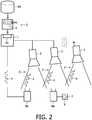
- a second embodiment of the inventionis shown in figure 2 .
- a second detector 8bis arranged to receive the signal 4 from one of the output beams 3 and is connected to the lighting management system 1.
- the detector 8bprovides the signal 4 to the lighting management system 1, which then compares the signal 4 with the identification tag 7. If the signal 4 does not correspond to the identification tag 7 or is missing entirely, the lighting management system 1 stops the generation of the control commands from the lighting design data 5.
- This setupmakes sure that the components of the lighting system support the underlying security system and assures that the signal 4 is comprised in the output beams. For example, it is not possible to filter the signal 4 from the control commands or from the output beams 3, which further enhances the security of the lighting system 3.
- the lighting units 2can be connected to the lighting management system 1 either wired or wireless, allowing a flexible set-up of the lighting system.
- the detector 8bmay be connected wirelessly to the lighting management system 1.
- Figure 3illustrates an alternative representation of lighting design data 5.
- the identification tag 7is embedded in the lighting definitions 6.
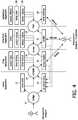
- FIG. 4An overview of the flow according to the method for composing a lighting atmosphere from an abstract description for a shop is depicted in Fig. 4 .
- a lighting atmosphere composition computer program with a graphical user interfaceGUI
- an abstract atmosphere description 10is created (in Fig. 4 also denoted as ab atmos desc ).
- the abstract atmosphere descriptioncan also be generated from one of the interaction methods depicted at the bottom of Fig. 4 .
- the abstract description 10merely contains descriptions of lighting effect at certain semantic locations at certain semantic times/occasions. The lighting effects are described by the type of light with certain parameters.
- the abstract description 10is shop layout and lighting system independent.
- the GUImay be for example possible to load a shop layout template containing the semantic locations. Then the designer can create the lighting effects and the atmosphere by for example drag and drop technology from a palette of available lighting devices.
- the output of the computer program with the GUImay be a XML file containing the abstract description 10.
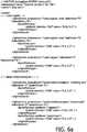
- FIG. 6A to 6CAn example of an XML file containing such an abstract atmosphere description is shown in Fig. 6A to 6C .
- elements of the light atmosphere descriptionare linked to semantic (functional) locations in the shop.
- the semantic locationsare introduced by the attribute "areaselector”.
- the lighting atmosphere at this semantic locationis introduced by the tag name "lighteffecttype”.
- the type of light with lighting parametersis described by the tag names "ambient”, “accent”, “architectural” and “wallwash”, as picture by using the tag names “architectural” and “picutrewallwash”, or as a lightdistribution.
- the shown pictureis specified by the attribute "pngfile” and its intensity.
- the intensityis specified, the colour at the corners of the area and possibly parameters specifying the s-curve of the gradient.
- the name of the owner of the lighting designis included in an identification tag "owner".
- the mapping loop 18uses an algorithm to control the light units or lamps, respectively, in such a way that the generated light differs as little as possible from the target 22.
- Various control algorithmscan be used, like classical optimization, neural networks, genetic algorithms etc.
- the mapping process 18receives a target light "scene" from the rendering process 16.
- the mapping process 18needs to know which lamps contribute in what way to the lighting of a certain physical location. This is done by introducing sensors, which can measure the effects of a lighting device or lamp, respectively, in the environment. Typical sensors are photodiodes adapted for measuring the lighting intensity, but also cameras (still picture, video) may be considered as specific examples of such sensors.
- a so-called dark room calibrationmay be done before the abstract atmosphere description 10 is transferred to the actual lamp control settings 24.
- the process of calibrationis done by driving the light units one by one. Cameras and/or sensors will measure the effect of the single light unit on the environment. Each camera or sensor corresponds to one view point. By measuring the effect in this way, influences of wall colours, furniture, carpet etc. are taken into account automatically. Beside measuring the effect of each light unit, it should be indicated which physical locations are measured for every camera and sensor. As far as cameras are concerned, the camera view itself can be used to indicate the physical locations of the shop.
- Fig. 5shows a possible set up for the calibration of a lighting system 50 with a camera
- the different views on the environmentare displayed on the management console 58.
- the installerindicates the physical locations e.g. with a pointing device (mouse, tablet).
- the viewsmay comprise pictures of a real shop and certain physical locations (shoebox1, shoebox2, isleX) in the shop indicated as highlighted sections in the picture, created by an installer on the management console 58.
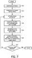
- the calibration processcomprises essentially the following steps:
- the atomic effectsare then used to realize the effects in the lighting design.
- step S10all lamps are deactivated, i.e. switched off.
- step S12the present lighting effects are measured and the measurement values are stored as dark light values.
- the lamps of the lighting systemare activated, i.e. switched on one by one by using a representative set of control values for the lamps (step S14).
- the effect of each lampsis measured at several different physical locations in step S16 until it is stable.
- step S18for every lamps the lighting effect on the environment is calculated by subtracting the stored dark light values from the stable measurement values of the effect of each lamps.
- step S20the lighting effect for the representative set of control values for each lamps is stored.
- step S22it is checked whether all lamps were already activated. If yes, the calibration process stops. If no, the process returns to step S 14.
- the measurements for the light effects in the viewsare compared and matched. Differences can have several reasons: e.g. the lamp provides ambient white light and the views are orthogonal so they have a different background, with maybe different colors. In such a case, the installer is triggered and has to select or describe the atomic effect via user interaction.
- a service discovery protocolmay detect them, and the lighting management system asks for features of the lamps. Representative control sets are generated, and a dark room calibration (only for these light units) can be started on demand or automatically.
Landscapes
- Circuit Arrangement For Electric Light Sources In General (AREA)
Description
- The invention relates to a lighting system and a method for operating a lighting system.
- Lighting systems with a plurality of lighting units are being used today for various applications, for example for room lighting applications to create defined lighting scenes.
US 2007/0258523 A1 discloses a lighting system with controllable lighting units. A PC is provided for controlling the lighting units through the addresses of the lighting units, stored in a signal control unit. WO2006/111934 relates to obtaining data about a lighting effect at a specific location caused by the operation of different lighting units and to control said operation dependent on said data and on location data, such that the light effect can be controlled for properties of the light effect dependent on location and the light effect can be dragged while maintaining properties of the light effect.WO2006/111927 relates to measuring lighting effects caused by the operation of different lighting units on their environment and to control said operation dependent on the measured effects.- The recent development of controllable light sources increases the possibilities for a lighting designer. Due to this, the design of lighting scenes rises in significance by allowing to apply various effects and atmospheres without a change in the lighting units. Consequently, such a lighting design can be regarded as a complex work product and thus intellectual property of the designer.
- A lighting design is usually implemented in programs or scripts for operating the respective lighting units. An undesirable side-effect of such programs is that copying is generally possible without much effort, enabling use of such lighting design without consent of the designer.
- Accordingly, it is an object of this invention to provide a lighting system and a method for operating a lighting system which allows an efficient commercial use of lighting designs.
- The object is solved according to the invention by a lighting system according to
claim 1 and a method for operating a lighting system according toclaim 9. Dependant claims relate to preferred embodiments of the invention. - The basic idea of the invention is the possibility to obtain an identification tag comprised in lighting design data directly from an output beam, i. e. from the emitted light of the at least one lighting unit. It is thus possible to trace any unauthorized distribution of a lighting design by monitoring the emitted light without the need to directly access any part of the lighting system.
- The lighting system comprises at least one controllable lighting unit for providing at least one output beam of light according to control commands, supplied by a controller. The lighting unit may be of any suitable type, for example a commercially available halogen, fluorescent or solid state lighting unit, as for instance an LED or an OLED. At least one parameter of the lighting unit is controllable, for example brightness, color, special effect, e.g. strobe light or a gobo, or the position of the output beam.
- For controlling the lighting unit, the controller supplies control commands to the lighting unit. The controller may be of any suitable type, for example a microcontroller, a computer or a lighting controller. The controller may be integrated with other components of the lighting system, for example with the lighting unit or a lamp driver, depending on the application. It may also be possible to provide multiple controllers, in case of the presence of more than one lighting unit in the lighting system, each providing control commands for a respective lighting unit or a group of lighting units.
- The controller comprises means for receiving the lighting design data, which may be of any suitable type. Exemplary, the means for receiving the lighting design data may be an interface for obtaining the lighting design data from a network or a storage medium, such as a memory card, a CD/DVD or a server.
- According to the invention, the controller is configured to generate said control commands from said lighting design data comprising an identification tag, wherein said control commands are generated so that said output beam comprises a detectable signal, corresponding to said identification tag.
- As mentioned before, it is thus possible to obtain the identification tag by monitoring the output beam of light and the contained detectable signal, for example, using a suitable detector, adapted to receive said signal and to retrieve said identification tag. It may although not be necessary, that the identification tag can be directly taken from the signal, as long as information is contained in the signal, which corresponds to said identification tag. For example, the detectable signal may comprise mapping information, allowing to retrieve the corresponding identification tag from a database. It is however preferred, that the identification tag is directly comprised in the emitted signal.
- The lighting design data comprises at least said identification tag together with a lighting definition for obtaining a specific lighting scene or a set of such lighting definitions, for example a sequence of lighting scenes in case of time-dependent lighting effects. Most simply, the lighting definitions may for example include specific control commands for setting at least one parameter of a lighting unit, although the invention is not limited hereto. Preferably, the lighting design data is digital data.
- According to the invention, the identification tag may be represented in the lighting design data in any suitable way. For example, the identification tag may be already implemented or embedded in the lighting definitions, for obtaining the lighting scenes. Alternatively, the identification tag may be comprised together with the lighting definitions in the lighting design data, which could be regarded as a data container. In this case, the controller "merges" the lighting definitions with the identification tag to generate said control commands for obtaining an output beam according to the lighting definitions comprising the detectable signal. In any case, the lighting design data should preferably be protected, so that the identification tag cannot be removed from the lighting design data.
- The identification tag may comprise any information relating to the lighting design data. The identification tag may for example contain metadata of the lighting design. Preferably, the identification tag comprises information, which enables to trace the origin of the lighting design data. Such information may for example include details with regard to the lighting designer, the owner or the licensee of the lighting design. For example, a lighting design for a hotel chain may comprise the name of the hotel. Most preferably, the identification tag comprises information, individualizing the lighting design data. Such information individually describes certain lighting design data and thus a certain lighting design. It is thus possible to clearly determine a specific lighting design, when obtaining the identification tag from the output beam, advantageously enabling to determine whether the lighting design data is used illicitly by directly monitoring the output beam of light.
- The identification tag may further or alternatively comprise information of the venue, for example an address of the shop, for which the lighting design has been made originally.
- According to a preferred embodiment of the invention, the lighting design data comprises abstract atmosphere definitions. Using abstract atmosphere definitions it is possible to describe a lighting scene independent of a location or venue of the set-up of the installed light sources. Because of the possibility of universal use, such lighting design data is especially vulnerable to misuse.
- In context of the present invention, the term "abstract atmosphere definition" means a definition of the atmosphere, i.e. the lighting scene, at a higher level of abstraction than a description of settings of the intensity, color or the like of every individual lighting unit of a lighting system. For example, the description of the type of a lighting scene such as "diffuse ambient lighting", "focused accent lighting" or "wall washing" is considered an abstract atmosphere definition. Further, the description of certain lighting parameters such as intensity, color or color gradient at certain semantic locations and/or certain semantic times, for example "blue with low intensity in the morning at the cash register"or "dark red with medium intensity at dinner time in the whole shopping area" is also considered an abstract atmosphere definition. Herein "semantic location" and "semantic time" means a description of a location or a time such as "cash register" in a shop, "lunch time" or "time > 22:00h" in contrast to a concrete description of a location, for example with coordinates or of a time with an exact expression of the time. When creating a lighting design using abstract atmosphere definitions it is possible to include some parameters as abstract definitions, while other parameters are defined as a concrete description of a setting.
- Lighting design data comprising abstract atmosphere definitions may preferably be generated from user input to which the identification tag is added before the lighting design data is supplied to the lighting system. For example, the user may define a lighting scene, such as "diffuse ambient lighting", as mentioned before. The identification tag is then added to the lighting design data and preferably encrypted, so that a removal of the identification tag is not possible. For obtaining the desired lighting, the abstract atmosphere definitions need to be rendered or mapped to control commands for the at least one lighting unit. Most preferably, the controller is configured to map the abstract atmosphere definitions to control commands for the at least one lighting unit.
- The detectable signal may be of any suitable type, allowing to transfer information in the output beam of light. For example, a modulation in brightness of the irradiated light, i.e. an amplitude modulation could be used to form the detectable signal. Further alternatives include a color or light temperature variation or a specific pattern, if the lighting unit provides for such controllable parameters. Instead of an amplitude modulation, other types of modulation known in the art, such as a pulse-width, pulse density, frequency or pulse-position modulation may be used.
- Preferably, the detectable signal is invisible to the human eye, so as not to interfere with any lighting effect. Exemplary, the detectable signal may be modulated with an amplitude modulation at a frequency above 100 Hz to make the modulation invisible or at least almost invisible to the human eye.
- Further methods for including invisible signals in lighting known in the art may be applied. For example, document
WO 2007/099472 A1 discloses a pulse-width modulation for modulating a beam of light and for transporting information therein. - Since it may be possible that an element is arranged in the lighting system, which prevents the distribution of the detectable signal in the output beam, it is preferred that the lighting system comprises at least one detector, arranged to detect said signal in the output beam and to supply information on said signal to the controller. The information enables the controller to compare the signal with the identification tag. Most simply, the information, provided by the detector may be the detected signal itself. Alternatively, the information may be already the identification tag, obtained by the detector from the signal. The controller then compares the information with the identification tag to determine any alteration between the detectable signal and the identification tag. For example, when a removal of the signal is detected, which would make it impossible to obtain the identification tag from the output beam, the controller may stop to further generate control commands for the connected lighting units and thus stop playback of the lighting design data. Alternatively or additionally, the controller may issue a corresponding message, for example to a connected display. Using this preferred embodiment, the overall security of the lighting system is advantageously further enhanced, since the avoidance of the distribution of the identification tag and thus avoidance of the security measures of the lighting system is not possible.
- According to a preferred embodiment, the lighting system comprises multiple lighting units for providing multiple output beams. The controller is configured to generate control commands so that each output beam comprises said detectable signal. The present embodiment thus advantageously simplifies the detection of the signal.
- Preferably, variable storing means are provided for storing the lighting design data and for supplying said lighting design data for the generation of said control commands. The storing means thus provide the lighting design data to the controller for generation of the control commands. The storing means may be integrated with the controller or may be a separate component, for example, a data server in a network or any type of memory or storage medium. The storing means may also be a part of a system for generation of lighting design data.
- As mentioned before, the lighting design data is preferably protected, so that the identification tag cannot be removed from the lighting design data.
- According to a preferred embodiment, the lighting design data is encrypted digital data and the controller has means for decrypting the lighting design data.
- For encrypting the lighting design data any suitable encryption method known in the art may be applied, which assures that the identification tag cannot be removed from the lighting design data.
- Most preferred, the lighting design data is encrypted, so that the "clear-text" design cannot be retrieved from the data. Using this preferred embodiment, only "trusted" controllers may decrypt the lighting design data, which further enhances the overall security of the system.
- In the present embodiment, the controller has suitable means for decryption, which may be implemented in hardware and/or software to be able to generate the control commands.
- Exemplary, the data may be encrypted using an encryption key, such as used in DES, blowfish or AES encryption methods. The key is only known to the designer of the lighting design data and to the controller, which then may decrypt the lighting design data using the specific algorithm. Alternatively, more advanced encryption methods may be used, such as public-key cryptography, for example used in PGP.
- The above and other objects, features and advantages of the present invention will become apparent from the following description of preferred embodiments, in which:
fig. 1 shows a first embodiment of a lighting system according to the invention,fig. 2 shows a second embodiment of a lighting system,fig. 3 shows an alternative representation of lighting design data,fig. 4 shows a flow diagram of an embodiment of a method for composing a lighting atmosphere from an abstract atmosphere definition;fig. 5 shows an embodiment of a set up of a lighting system with a camera and sensors for composing a lighting atmosphere from an abstract atmosphere definition;fig. 6a-6c shows an XML file as an embodiment of an abstract atmosphere definition; andfig. 7 shows a detailed sequence of steps of an embodiment of a calibration process.- In the following description, the terms "lighting device", "lighting unit", "light unit" and "lamp" are used as synonyms. These terms mean herein any kind of electrically
controllable lighting device such as a semiconductor-based illumination unit such as an LED, an OLED, a halogen bulb, a fluorescent lamp, a light bulb. Furthermore, (functional) similar or identical elements in the drawings may be denoted with the same reference numerals. Figure 1 shows a first embodiment of a lighting system according to the invention. A controller, here alighting management system 1 is connected tocontrollable lighting units 2 to illuminate a room with specific lighting scenes. Thelighting units 2 comprise high-power LEDs and are controllable at least in terms of brightness and color. Thelighting management system 1 supplies control commands to thelighting units 2 for providingoutput beams 3. The control commands are generated by the lighting management system fromlighting design data 5, received by aninterface 33. The lighting design data is supplied to thelighting management system 1 from avariable database 34. Thelighting design data 5 comprisesseveral lighting definitions 6 together with anidentification tag 7. Thelighting definitions 6 are abstract atmosphere definitions as described with reference tofig. 4 - 7 , which are used by thelighting management system 1 to generate the control commands for thelighting units 2 to obtain the desired lighting scenes. Theidentification tag 7 comprises the name of the owner of the lighting design.- The
lighting management system 1 generates the control commands, so that theoutput beams 3 of thelighting units 2 comprise adetectable signal 4, which corresponds to theidentification tag 7. Thesignal 4 is then be interpreted by asuitable detector 8a to obtain theidentification tag 7. The information comprised in theidentification tag 7, i.e. the name of the owner of the lighting design is then shown on adisplay 9. It is thus possible to obtain theidentification tag 7 directly from theoutput beams 3 to determine if the lighting design is used legally. - For generating the
detectable signal 4, thelighting management system 1 generates control commands, modulating the brightness of thelighting units 2 with a pulse-width modulation. The frequency of the pulse width modulation is chosen above 400 Hz, which makes the modulation invisible to the human eye. The brightness of the emitted light of thelighting units 2 is adjusted by varying the duty cycle of the pulse-width modulation. - A second embodiment of the invention is shown in
figure 2 . Here, asecond detector 8b is arranged to receive thesignal 4 from one of theoutput beams 3 and is connected to thelighting management system 1. Thedetector 8b provides thesignal 4 to thelighting management system 1, which then compares thesignal 4 with theidentification tag 7. If thesignal 4 does not correspond to theidentification tag 7 or is missing entirely, thelighting management system 1 stops the generation of the control commands from thelighting design data 5. This setup makes sure that the components of the lighting system support the underlying security system and assures that thesignal 4 is comprised in the output beams. For example, it is not possible to filter thesignal 4 from the control commands or from theoutput beams 3, which further enhances the security of thelighting system 3. - As can be further seen from
figure 2 , thelighting units 2 can be connected to thelighting management system 1 either wired or wireless, allowing a flexible set-up of the lighting system. Although not shown, also thedetector 8b may be connected wirelessly to thelighting management system 1.Figure 3 illustrates an alternative representation oflighting design data 5. Here, theidentification tag 7 is embedded in thelighting definitions 6. - Several modifications to the above embodiments are possible:
- The
signal 4 may be incorporated in theoutput beams 3 with different modulations, for example pulse-density modulation.Signal 4 may also be a colour or light temperature modulation. - The
database 34 may be formed integrally with thelighting management system 1. - The
identification tag 7 may comprise further or additional information, for example metadata of the lighting design. - The
lighting definitions 6 may comprise concrete control commands for thelighting units 2, instead of abstract atmosphere definitions. - The
detector 8b may be configured to obtain theidentification tag 7 from thesignal 4 and to provide the obtainedidentification tag 7 to thelighting management system 1, instead of providing thesignal 4 to thelighting management system 1. Lighting design data 5 may be encrypted data to further enhance the overall security and to assure that theidentification tag 7 cannot be removed from thelighting design data 5. In this case, thelighting management system 1, e.g. theinterface 33, may provide decryption means. Such decryption means may be implemented in hardware and/or software.Lighting design data 5 may for example be encrypted using an encryption key, such as used in DES, blowfish or AES encryption methods. The key is supplied to thelighting management system 1, e.g. theinterface 33, which then may decrypt the lighting design data using the specific algorithm. Alternatively, more advanced encryption methods may be used, such as public-key cryptography, for example used in PGP.- The
signal 4 may comprise a reference to theidentification tag 7, instead of a representation of theidentification tag 7 itself, allowing to retrieve theidentification tag 7 from a data storage. - At least some of the functionality of the
lighting management system 1 may be implemented in software. - The generation of abstract atmosphere definitions and the use of such definitions in a lighting system to generate control commands for
lighting units 2 is explained with reference tofigures 4 - 7 . In the following, the terms "abstract atmosphere definition", "abstract atmosphere description" and "abstract description" are used as synonyms. - An overview of the flow according to the method for composing a lighting atmosphere from an abstract description for a shop is depicted in
Fig. 4 . Via somedesign process 11, for example by using a lighting atmosphere composition computer program with a graphical user interface (GUI), anabstract atmosphere description 10 is created (inFig. 4 also denoted asab atmos desc). The abstract atmosphere description can also be generated from one of the interaction methods depicted at the bottom ofFig. 4 . Theabstract description 10 merely contains descriptions of lighting effect at certain semantic locations at certain semantic times/occasions. The lighting effects are described by the type of light with certain parameters. Theabstract description 10 is shop layout and lighting system independent. Thus, it may be created by a lighting designer without knowledge about a specific lighting system and lighting environment such as a room layout. The designer must know only semantic locations of the lighting environment, for example "cash register" or "shoe box 1", "shoe box 2", "changing cubicle", "coat stand" in a shoe or fashion shop. When using a GUI for creating theabstract description 10, it may be for example possible to load a shop layout template containing the semantic locations. Then the designer can create the lighting effects and the atmosphere by for example drag and drop technology from a palette of available lighting devices. The output of the computer program with the GUI may be a XML file containing theabstract description 10. - An example of an XML file containing such an abstract atmosphere description is shown in
Fig. 6A to 6C . In the abstract atmosphere description, elements of the light atmosphere description are linked to semantic (functional) locations in the shop. As can be seen inFig. 6A to 6C , the semantic locations are introduced by the attribute "areaselector". The lighting atmosphere at this semantic location is introduced by the tag name "lighteffecttype". The type of light with lighting parameters is described by the tag names "ambient", "accent", "architectural" and "wallwash", as picture by using the tag names "architectural" and "picutrewallwash", or as a lightdistribution. The parameters are described by the attributes "intensity", for example of 2000 (lux/nit), and "color", for example x=0.3, y=0.3. In case of a picture wall washing effect the shown picture is specified by the attribute "pngfile" and its intensity. In case of a light distribution, the intensity is specified, the colour at the corners of the area and possibly parameters specifying the s-curve of the gradient. Furthermore, for some lights fading in and out may be specified by the attributes "fadeintime" and "fadeouttime". The name of the owner of the lighting design is included in an identification tag "owner". - Such an abstract description is automatically translated into control values for the different lighting devices or units, i.e., lamps of a specific instance of a lighting system (in
Fig. 4 denominated as lamp settings 24) in three stages: - 1. Compiling 14 the
abstract description 10 into an atmosphere model 20: In the compilestage 14, the abstract (shop layout and light infrastructure independent)atmosphere description 10 is translated into a shop layout dependent atmosphere description. This implies that thesemantic locations 12 are replaced by real locations in the shop (physical locations). This requires at minimum some model of the shop with an indication of the physical locations and for each physical location which semantic meaning it has (e.g. one shop can have more than one cash register. These all have different names, but the same semantics). This information is available in the shop layout. Beside the semantic locations, also semantic notions of time (e.g. opening hours) are replaced by the actual values (e.g. 9:00 - 18:00). This information is available in the shop timing. Furthermore, for light effects that depend on sensor readings, an abstract sensor is replaced by the (identifier of the) real sensor in the shop. These shop dependent values are contained in a shop definitions file 12 containing specific parameters or the shop and the applied lighting system. The shop definitions contain the vocabulary that can be used in the abstract atmosphere, shop layout and shop timing. The output of the compiler stage is the so called atmosphere model 20 (atmos model), which still contains dynamics, time dependencies and sensor dependencies. - 2.
Rendering 16 theatmosphere model 20 to a target 22: In the rendering stage, all dynamics, time dependencies and sensor dependencies are removed from theatmosphere model 20. As such, the render stage creates a snapshot of the light atmosphere at a certain point in time and given sensor readings at that point in time. The output of the render stage is called thetarget 22. Thetarget 22 can consist of one or more view points (see dark room calibration) and per view point a color distribution, an intensity distribution, a CRI (Color Rendering Index) distribution, ... - 3.
Mapping 18 thetarget 22 into actual control values 24 for lighting devices, i.e. the lamp: The mapping stage converts thetarget 22 into actual lamp control values 24 (lamp settings). In order to calculate thesecontrol values 24, the mapping loops requires:- a. Descriptions of the
lamps 26 available in the lighting system, like the type of lamp, color space, ... - b. The so-called
atomic effects 26 which describe which lamp contributes in what way to the lighting of a certain physical location. How these atomic effects are generated is described below. - c. In case of controlling the lights with a closed feedback loop, the sensor values 28 to measure the generated light.
- a. Descriptions of the
- Based on these
inputs target 22, themapping loop 18 uses an algorithm to control the light units or lamps, respectively, in such a way that the generated light differs as little as possible from thetarget 22. Various control algorithms can be used, like classical optimization, neural networks, genetic algorithms etc. - As already indicated, the
mapping process 18 receives a target light "scene" from therendering process 16. In order to calculate thelamp settings 24 required to generate light that approximates thetarget 22 as close as possible, themapping process 18 needs to know which lamps contribute in what way to the lighting of a certain physical location. This is done by introducing sensors, which can measure the effects of a lighting device or lamp, respectively, in the environment. Typical sensors are photodiodes adapted for measuring the lighting intensity, but also cameras (still picture, video) may be considered as specific examples of such sensors. - In order to achieve an exact mapping result which matches the
target 22 as close as possible, a so-called dark room calibration may be done before theabstract atmosphere description 10 is transferred to the actuallamp control settings 24. The process of calibration is done by driving the light units one by one. Cameras and/or sensors will measure the effect of the single light unit on the environment. Each camera or sensor corresponds to one view point. By measuring the effect in this way, influences of wall colours, furniture, carpet etc. are taken into account automatically. Beside measuring the effect of each light unit, it should be indicated which physical locations are measured for every camera and sensor. As far as cameras are concerned, the camera view itself can be used to indicate the physical locations of the shop. Fig. 5 shows a possible set up for the calibration of alighting system 50 with a camera- 52 and
several sensors 54. The shownlighting system 54 contains:- Controllable
light units 54. - Several (light)
sensors 53 and acamera 52 infrastructure that can measure the effects of lights created by thelight units 54 on the environment. - A
lighting management system 56 that can drive thelight units 54 and interpret the measurements taken by thecamera 52 and thesensors 53. Thelighting management system 56 may be implemented by a computer program, executed for example by a Personal Computer (PC). - A
management console 58 that displays the views, and is used for interaction with the installer of thelighting management system 56. Sub areas of the view can be selected and related to physical locations of the target environment. Themanagement console 58 can be located close to the target environment, but also remote from the lighting management system. (e.g. in the chain headquarters). In case of a remote location of themanagement console 58, thelighting management system 56 is connected to a computer network, such as the internet, in order to allow a remote management via themanagement console 58.
- Controllable
- The different views on the environment are displayed on the
management console 58. In these views, the installer indicates the physical locations e.g. with a pointing device (mouse, tablet). The views may comprise pictures of a real shop and certain physical locations (shoebox1, shoebox2, isleX) in the shop indicated as highlighted sections in the picture, created by an installer on themanagement console 58. - During dark room calibration, the effects of the
light units 54 on the environment and thus the physical locations are measured. In the dark room calibration procedure, the effects of thedifferent light units 54 are tested in conditions which are constant and measurable. The best conditions are those where daylight is at minimum (e.g. at night, with closed blinds). The calibration process comprises essentially the following steps: - First, the
light management system 56 turns all thelight units 54 off, and measures the lighting effects that are present. These will be subtracted from the measured effects of the lights later on. In dark room conditions, this background effect is nihil or very small. - Then
light units 54 are driven one by one, a representative set of control values is used. This control set shows the features of thelight units 54 one by one. For everylight unit 54 and control setting, the effect on the environment is described and stored (atomic effect). - The atomic effects are then used to realize the effects in the lighting design.
- The detailed sequence of steps of the calibration process is shown in
Fig. 7 . In step S10, all lamps are deactivated, i.e. switched off. Then, in step S12 the present lighting effects are measured and the measurement values are stored as dark light values. Afterwards, the lamps of the lighting system are activated, i.e. switched on one by one by using a representative set of control values for the lamps (step S14). The effect of each lamps is measured at several different physical locations in step S16 until it is stable. In the following step S18, for every lamps the lighting effect on the environment is calculated by subtracting the stored dark light values from the stable measurement values of the effect of each lamps. In step S20, the lighting effect for the representative set of control values for each lamps is stored. In step S22, it is checked whether all lamps were already activated. If yes, the calibration process stops. If no, the process returns to stepS 14. - If the same physical location appears in two view points, the measurements for the light effects in the views are compared and matched. Differences can have several reasons: e.g. the lamp provides ambient white light and the views are orthogonal so they have a different background, with maybe different colors. In such a case, the installer is triggered and has to select or describe the atomic effect via user interaction.
- When light units are added to the calibrated system, a service discovery protocol may detect them, and the lighting management system asks for features of the lamps. Representative control sets are generated, and a dark room calibration (only for these light units) can be started on demand or automatically.
- The invention has been illustrated and described in detail in the drawings and foregoing description. Such illustration and description are to be considered illustrative or exemplary and not restrictive; the invention is not limited to the disclosed embodiments.
- In the claims, the word "comprising" does not exclude other elements, and the indefinite article "a" or "an" does not exclude a plurality. The mere fact that certain measures are recited in mutually different dependent claims does not indicate that a combination of these measures cannot be used to advantage. Any reference signs in the claims should not be construed as limiting the scope.
Claims (12)
- A lighting system, comprising:- at least one controllable lighting unit (2) for providing an output beam of light (3) and- a controller for supplying control commands to the at least one lighting unit (2), having means for receiving lighting design data (5) comprising identification information (7) relating to the lighting design data, which controller is configured to generate said control commands from said received lighting design data (5), said control commands are generated so that said output beam (3) comprises a detectable signal (4), which corresponds to said identification information, wherein the lighting system ischaracterized in that said identification information (7) comprises information, individualizing the lighting design data (5).
- Lighting system according to any of the preceding claims, wherein said lighting design data (5) comprises abstract atmosphere definitions.
- Lighting system according any of the preceding claims, wherein said detectable signal (4) is invisible to the human eye.
- Lighting system according to any of the preceding claims, comprising at least one detector, arranged to detect said signal in said output beam (3), wherein the detector is configured to supply information on said signal (4) to said controller for comparing said signal (4) with said identification information (7) so that the generation of control commands is stopped, when said signal (4) does not correspond to said identification information (7).
- Lighting system according to any of the preceding claims, wherein multiple lighting units (2) are arranged for providing multiple output beams (3) and said controller is configured to generate said control commands so that each output beam (3) comprises said detectable signal (4).
- Lighting system according any of the preceding claims, wherein variable storing means are provided for storing said lighting design data (5), which supply said lighting design data (5) for said generation of said control commands.
- Lighting system according to any of the preceding claims, wherein the lighting design data (5) is encrypted digital data and the controller having means for decrypting the lighting design data (5).
- A controller for use in a lighting system with at least one lighting unit (2) for providing an output beam (3), having means for receiving lighting design data (5), which controller is configured to generate control commands from said received lighting design data (5) comprising identification information (7) relating to the lighting design data, said control commands are generated so that said output beam (3) comprises a detectable signal (4), which corresponds to said identification information (7) wherein the controller ischaracterized in that said identification information (7) comprises information, individualizing the lighting design data (5).
- Method for operating a lighting system with at least one lighting unit (2) for providing an output beam of light (3) in which- lighting design data (5) is received,- control commands are generated from said received lighting design data (5) including identification information (7) relating to the lighting design data, and said control commands are generated so that said output beam (3) comprises a detectable signal (4), which corresponds to said identification information (7) and- the control commands are supplied to the at least one lighting unit (2), the methodcharacterized in that said identification information (7) comprises information, individualizing the lighting design data (5).
- Method according to claim 9 in which- said signal (4) is detected from the output beam (3) and- said signal (4) is compared with said identification information (7), so that the generation of the control commands is stopped, when said signal (4) does not correspond to said identification information (7).
- A computer program enabling to carry out the method according to one of the claims 9-10 when executed by a computer.
- A data-carrier comprising the computer program according to claim 11.
Priority Applications (1)
| Application Number | Priority Date | Filing Date | Title |
|---|---|---|---|
| EP09705563.6AEP2238812B1 (en) | 2008-01-30 | 2009-01-26 | Lighting system and method for operating a lighting system |
Applications Claiming Priority (3)
| Application Number | Priority Date | Filing Date | Title |
|---|---|---|---|
| EP08101106 | 2008-01-30 | ||
| PCT/IB2009/050295WO2009095833A1 (en) | 2008-01-30 | 2009-01-26 | Lighting system and method for operating a lighting system |
| EP09705563.6AEP2238812B1 (en) | 2008-01-30 | 2009-01-26 | Lighting system and method for operating a lighting system |
Publications (2)
| Publication Number | Publication Date |
|---|---|
| EP2238812A1 EP2238812A1 (en) | 2010-10-13 |
| EP2238812B1true EP2238812B1 (en) | 2017-11-22 |
Family
ID=40637740
Family Applications (1)
| Application Number | Title | Priority Date | Filing Date |
|---|---|---|---|
| EP09705563.6AActiveEP2238812B1 (en) | 2008-01-30 | 2009-01-26 | Lighting system and method for operating a lighting system |
Country Status (8)
| Country | Link |
|---|---|
| US (2) | US10045430B2 (en) |
| EP (1) | EP2238812B1 (en) |
| JP (1) | JP5519533B2 (en) |
| KR (1) | KR20100120292A (en) |
| CN (1) | CN101933399B (en) |
| ES (1) | ES2657702T3 (en) |
| TW (1) | TW200950590A (en) |
| WO (1) | WO2009095833A1 (en) |
Families Citing this family (34)
| Publication number | Priority date | Publication date | Assignee | Title |
|---|---|---|---|---|
| US8740701B2 (en) | 2009-06-15 | 2014-06-03 | Wms Gaming, Inc. | Controlling wagering game system audio |
| WO2011005798A1 (en) | 2009-07-07 | 2011-01-13 | Wms Gaming, Inc. | Controlling wagering game lighting content |
| WO2011005797A1 (en) | 2009-07-07 | 2011-01-13 | Wms Gaming, Inc. | Controlling gaming effects for gaming network nodes |
| US10269207B2 (en) | 2009-07-31 | 2019-04-23 | Bally Gaming, Inc. | Controlling casino lighting content and audio content |
| US9011247B2 (en) | 2009-07-31 | 2015-04-21 | Wms Gaming, Inc. | Controlling casino lighting content and audio content |
| US8622830B2 (en)* | 2009-08-20 | 2014-01-07 | Wms Gaming, Inc. | Controlling sound distribution in wagering game applications |
| EP2494712B1 (en)* | 2009-10-28 | 2017-01-25 | Philips Lighting Holding B.V. | Commissioning coded light sources |
| US8613667B2 (en) | 2009-12-21 | 2013-12-24 | Wms Gaming, Inc. | Position-based lighting coordination in wagering game systems |
| US8840464B1 (en) | 2010-04-26 | 2014-09-23 | Wms Gaming, Inc. | Coordinating media in a wagering game environment |
| US8814673B1 (en) | 2010-04-26 | 2014-08-26 | Wms Gaming, Inc. | Presenting lighting content in wagering game systems |
| US9367987B1 (en) | 2010-04-26 | 2016-06-14 | Bally Gaming, Inc. | Selecting color in wagering game systems |
| US8912727B1 (en) | 2010-05-17 | 2014-12-16 | Wms Gaming, Inc. | Wagering game lighting device chains |
| US8827805B1 (en) | 2010-08-06 | 2014-09-09 | Wms Gaming, Inc. | Balancing community gaming effects |
| US8687914B2 (en)* | 2010-10-13 | 2014-04-01 | Ability Enterprise Co., Ltd. | Method of producing an image |
| US9400856B2 (en)* | 2012-05-16 | 2016-07-26 | Marc Striegel | System and method for generating a lighting plan |
| DE102012209750A1 (en)* | 2012-06-12 | 2013-12-12 | Zumtobel Lighting Gmbh | Apparatus for operating light source e.g. LED module of lamp, has main structure to modify light output during operation of light sources such that light output of optical signature encodes manufacturer information |
| WO2014053954A1 (en)* | 2012-10-05 | 2014-04-10 | Koninklijke Philips N.V. | A method of self-calibrating a lighting device and a lighting device performing the method |
| CN104770066B (en)* | 2012-10-05 | 2017-11-07 | 飞利浦灯具控股公司 | Examine the authenticity of lighting apparatus |
| WO2014064634A1 (en)* | 2012-10-24 | 2014-05-01 | Koninklijke Philips N.V. | Assisting a user in selecting a lighting device design |
| WO2014087274A1 (en)* | 2012-10-24 | 2014-06-12 | Koninklijke Philips N.V. | Assisting a user in selecting a lighting device design |
| US10467670B2 (en) | 2012-10-24 | 2019-11-05 | Signify Holdng B.V. | Assisting a user in selecting a lighting device design |
| US9007418B2 (en)* | 2012-11-29 | 2015-04-14 | Cisco Technology, Inc. | Capturing video through a display |
| JP6306149B2 (en)* | 2013-04-19 | 2018-04-04 | フィリップス ライティング ホールディング ビー ヴィ | Coded illumination device and product information system having such a coded illumination device |
| WO2015036886A2 (en)* | 2013-09-10 | 2015-03-19 | Koninklijke Philips N.V. | External control lighting systems based on third party content |
| JP6486944B2 (en) | 2013-09-23 | 2019-03-20 | フィリップス ライティング ホールディング ビー ヴィ | LIGHTING DEVICE AND METHOD OF PROTECTING THE LIGHTING DEVICE |
| EP2890223B1 (en)* | 2013-12-27 | 2020-05-27 | Panasonic Intellectual Property Corporation of America | Method for controlling mobile terminal and program for controlling mobile terminal |
| RU2015145160A (en) | 2014-01-21 | 2017-04-25 | Филипс Лайтинг Холдинг Б.В. | LIGHTING SYSTEM AND METHOD FOR MANAGING A LIGHTING SYSTEM |
| US9672768B2 (en)* | 2014-06-24 | 2017-06-06 | Xi'an Novastar Tech Co., Ltd. | Luminance-chrominance calibration production line of LED display module |
| WO2016206991A1 (en)* | 2015-06-23 | 2016-12-29 | Philips Lighting Holding B.V. | Gesture based lighting control |
| KR102546654B1 (en) | 2015-12-11 | 2023-06-23 | 삼성전자주식회사 | Lighting system, lighting device and a control method of the same |
| US11233854B2 (en)* | 2016-02-14 | 2022-01-25 | Signify Holding B.V. | Lighting control data identification |
| US10412802B2 (en)* | 2017-03-02 | 2019-09-10 | Osram Sylvania Inc. | Luminaire with programmable light distribution |
| CN110709896A (en)* | 2017-06-01 | 2020-01-17 | 昕诺飞控股有限公司 | System and method for rendering virtual objects |
| EP4205512B1 (en)* | 2020-08-31 | 2024-12-11 | Signify Holding B.V. | A controller for mapping a light scene onto a plurality of lighting units and a method thereof |
Citations (3)
| Publication number | Priority date | Publication date | Assignee | Title |
|---|---|---|---|---|
| WO2005058442A1 (en)* | 2003-12-12 | 2005-06-30 | Koninklijke Philips Electronics N.V. | Assets and effects |
| US20050275626A1 (en)* | 2000-06-21 | 2005-12-15 | Color Kinetics Incorporated | Entertainment lighting system |
| WO2006112009A1 (en)* | 2005-04-13 | 2006-10-26 | Hitachi, Ltd. | Atmosphere control device |
Family Cites Families (21)
| Publication number | Priority date | Publication date | Assignee | Title |
|---|---|---|---|---|
| US5009523A (en) | 1989-07-20 | 1991-04-23 | The Timken Company | Double row bearing assembly |
| JPH06310284A (en)* | 1993-04-28 | 1994-11-04 | Toshiba Lighting & Technol Corp | Lighting control device and lighting device |
| WO1996024894A1 (en) | 1995-02-08 | 1996-08-15 | Sega Enterprises, Ltd. | Information processor having security check function |
| US6333605B1 (en)* | 1999-11-02 | 2001-12-25 | Energy Savings, Inc. | Light modulating electronic ballast |
| US7161556B2 (en)* | 2000-08-07 | 2007-01-09 | Color Kinetics Incorporated | Systems and methods for programming illumination devices |
| AU2001285408A1 (en)* | 2000-08-07 | 2002-02-18 | Color Kinetics Incorporated | Automatic configuration systems and methods for lighting and other applications |
| JP4547269B2 (en) | 2002-12-19 | 2010-09-22 | コーニンクレッカ フィリップス エレクトロニクス エヌ ヴィ | How to configure a wirelessly controlled lighting system |
| EP1460841A1 (en) | 2003-03-19 | 2004-09-22 | Koninklijke Philips Electronics N.V. | Method of preventing making of unauthorized recordings |
| CN1582079B (en)* | 2003-08-15 | 2011-09-21 | 广东华南家电研究院 | Scene lighting system and its control method |
| CN1585585B (en)* | 2003-08-23 | 2010-05-12 | 珠海爱圣特电子科技有限公司 | A kind of intelligent lighting system control method |
| WO2005107337A1 (en)* | 2004-05-05 | 2005-11-10 | Koninklijke Philips Electronics N.V. | Lighting device with user interface for light control |
| JP5030943B2 (en)* | 2005-04-22 | 2012-09-19 | コーニンクレッカ フィリップス エレクトロニクス エヌ ヴィ | Lighting device control method and control system |
| WO2006111927A1 (en)* | 2005-04-22 | 2006-10-26 | Koninklijke Philips Electronics N.V. | Method and system for lighting control |
| JP5091114B2 (en)* | 2005-04-22 | 2012-12-05 | コーニンクレッカ フィリップス エレクトロニクス エヌ ヴィ | Lighting control |
| JP2007066585A (en)* | 2005-08-29 | 2007-03-15 | Toshiba Lighting & Technology Corp | Lighting system |
| JP5123195B2 (en)* | 2005-11-01 | 2013-01-16 | コーニンクレッカ フィリップス エレクトロニクス エヌ ヴィ | Method, system and remote controller for controlling respective settings of a plurality of spotlights |
| EP1966753A2 (en) | 2005-12-22 | 2008-09-10 | Koninklijke Philips Electronics N.V. | Script synchronization by watermarking |
| JP5162099B2 (en) | 2006-02-21 | 2013-03-13 | パナソニック株式会社 | Sleep environment control device |
| US8150269B2 (en) | 2006-03-02 | 2012-04-03 | Koninklijke Philips Electronics N.V. | Lighting device |
| US7429982B2 (en)* | 2006-05-05 | 2008-09-30 | Opto Tech Corp. | Digital lighting control system |
| US7961075B2 (en)* | 2007-05-30 | 2011-06-14 | Glp German Light Products Gmbh | Programmable lighting unit and remote control for a programmable lighting unit |
- 2009
- 2009-01-23TWTW098103114Apatent/TW200950590A/enunknown
- 2009-01-26KRKR1020107019281Apatent/KR20100120292A/ennot_activeWithdrawn
- 2009-01-26JPJP2010544826Apatent/JP5519533B2/enactiveActive
- 2009-01-26CNCN2009801037528Apatent/CN101933399B/enactiveActive
- 2009-01-26USUS12/864,520patent/US10045430B2/enactiveActive
- 2009-01-26EPEP09705563.6Apatent/EP2238812B1/enactiveActive
- 2009-01-26WOPCT/IB2009/050295patent/WO2009095833A1/enactiveApplication Filing
- 2009-01-26ESES09705563.6Tpatent/ES2657702T3/enactiveActive
- 2018
- 2018-05-03USUS15/970,011patent/US10362662B2/enactiveActive
Patent Citations (3)
| Publication number | Priority date | Publication date | Assignee | Title |
|---|---|---|---|---|
| US20050275626A1 (en)* | 2000-06-21 | 2005-12-15 | Color Kinetics Incorporated | Entertainment lighting system |
| WO2005058442A1 (en)* | 2003-12-12 | 2005-06-30 | Koninklijke Philips Electronics N.V. | Assets and effects |
| WO2006112009A1 (en)* | 2005-04-13 | 2006-10-26 | Hitachi, Ltd. | Atmosphere control device |
Also Published As
| Publication number | Publication date |
|---|---|
| US20180255621A1 (en) | 2018-09-06 |
| CN101933399A (en) | 2010-12-29 |
| CN101933399B (en) | 2013-11-13 |
| ES2657702T3 (en) | 2018-03-06 |
| WO2009095833A1 (en) | 2009-08-06 |
| EP2238812A1 (en) | 2010-10-13 |
| US10045430B2 (en) | 2018-08-07 |
| JP2011511407A (en) | 2011-04-07 |
| US20100309016A1 (en) | 2010-12-09 |
| US10362662B2 (en) | 2019-07-23 |
| TW200950590A (en) | 2009-12-01 |
| JP5519533B2 (en) | 2014-06-11 |
| KR20100120292A (en) | 2010-11-15 |
Similar Documents
| Publication | Publication Date | Title |
|---|---|---|
| US10362662B2 (en) | Lighting system and method for operating a lighting system | |
| US8324826B2 (en) | Method and device for composing a lighting atmosphere from an abstract description and lighting atmosphere composition system | |
| JP5103520B2 (en) | Method and system for automatically verifying the possibility of rendering a lighting environment from an abstract description | |
| JP5199278B2 (en) | Method and system for automatically verifying the possibility of rendering a lighting environment from an abstract description | |
| JP5519496B2 (en) | Lighting control system with user interface for interactively changing settings of lighting system, and method for interactively changing settings of lighting system using user interface | |
| CN105517255B (en) | Remote illumination controls | |
| EP2982221B1 (en) | Apparatus and methods for activatable lighting devices | |
| CN109041372B (en) | Method and apparatus for controlling lighting | |
| JP2010532079A5 (en) | ||
| CN109219987A (en) | connected lighting system | |
| JP2010528413A5 (en) | ||
| WO2009004586A1 (en) | Apparatus and method for modifying a light scene | |
| GB2553566A (en) | Control of output devices |
Legal Events
| Date | Code | Title | Description |
|---|---|---|---|
| PUAI | Public reference made under article 153(3) epc to a published international application that has entered the european phase | Free format text:ORIGINAL CODE: 0009012 | |
| 17P | Request for examination filed | Effective date:20100830 | |
| AK | Designated contracting states | Kind code of ref document:A1 Designated state(s):AT BE BG CH CY CZ DE DK EE ES FI FR GB GR HR HU IE IS IT LI LT LU LV MC MK MT NL NO PL PT RO SE SI SK TR | |
| AX | Request for extension of the european patent | Extension state:AL BA RS | |
| DAX | Request for extension of the european patent (deleted) | ||
| RAP1 | Party data changed (applicant data changed or rights of an application transferred) | Owner name:KONINKLIJKE PHILIPS N.V. Owner name:PHILIPS INTELLECTUAL PROPERTY & STANDARDS GMBH | |
| 17Q | First examination report despatched | Effective date:20140206 | |
| RAP1 | Party data changed (applicant data changed or rights of an application transferred) | Owner name:PHILIPS LIGHTING HOLDING B.V. | |
| GRAP | Despatch of communication of intention to grant a patent | Free format text:ORIGINAL CODE: EPIDOSNIGR1 | |
| INTG | Intention to grant announced | Effective date:20170613 | |
| RIN1 | Information on inventor provided before grant (corrected) | Inventor name:BUDDE, WOLFGANG, O. Inventor name:WENDT, MATTHIAS Inventor name:LEMMA, AWEKE, N. | |
| GRAS | Grant fee paid | Free format text:ORIGINAL CODE: EPIDOSNIGR3 | |
| GRAA | (expected) grant | Free format text:ORIGINAL CODE: 0009210 | |
| AK | Designated contracting states | Kind code of ref document:B1 Designated state(s):AT BE BG CH CY CZ DE DK EE ES FI FR GB GR HR HU IE IS IT LI LT LU LV MC MK MT NL NO PL PT RO SE SI SK TR | |
| REG | Reference to a national code | Ref country code:GB Ref legal event code:FG4D | |
| REG | Reference to a national code | Ref country code:CH Ref legal event code:EP | |
| REG | Reference to a national code | Ref country code:IE Ref legal event code:FG4D | |
| REG | Reference to a national code | Ref country code:AT Ref legal event code:REF Ref document number:949521 Country of ref document:AT Kind code of ref document:T Effective date:20171215 | |
| REG | Reference to a national code | Ref country code:DE Ref legal event code:R096 Ref document number:602009049479 Country of ref document:DE | |
| REG | Reference to a national code | Ref country code:FR Ref legal event code:PLFP Year of fee payment:10 | |
| REG | Reference to a national code | Ref country code:ES Ref legal event code:FG2A Ref document number:2657702 Country of ref document:ES Kind code of ref document:T3 Effective date:20180306 | |
| REG | Reference to a national code | Ref country code:NL Ref legal event code:MP Effective date:20171122 | |
| REG | Reference to a national code | Ref country code:LT Ref legal event code:MG4D | |
| REG | Reference to a national code | Ref country code:AT Ref legal event code:MK05 Ref document number:949521 Country of ref document:AT Kind code of ref document:T Effective date:20171122 | |
| PG25 | Lapsed in a contracting state [announced via postgrant information from national office to epo] | Ref country code:FI Free format text:LAPSE BECAUSE OF FAILURE TO SUBMIT A TRANSLATION OF THE DESCRIPTION OR TO PAY THE FEE WITHIN THE PRESCRIBED TIME-LIMIT Effective date:20171122 Ref country code:LT Free format text:LAPSE BECAUSE OF FAILURE TO SUBMIT A TRANSLATION OF THE DESCRIPTION OR TO PAY THE FEE WITHIN THE PRESCRIBED TIME-LIMIT Effective date:20171122 Ref country code:NL Free format text:LAPSE BECAUSE OF FAILURE TO SUBMIT A TRANSLATION OF THE DESCRIPTION OR TO PAY THE FEE WITHIN THE PRESCRIBED TIME-LIMIT Effective date:20171122 Ref country code:SE Free format text:LAPSE BECAUSE OF FAILURE TO SUBMIT A TRANSLATION OF THE DESCRIPTION OR TO PAY THE FEE WITHIN THE PRESCRIBED TIME-LIMIT Effective date:20171122 Ref country code:NO Free format text:LAPSE BECAUSE OF FAILURE TO SUBMIT A TRANSLATION OF THE DESCRIPTION OR TO PAY THE FEE WITHIN THE PRESCRIBED TIME-LIMIT Effective date:20180222 | |
| PG25 | Lapsed in a contracting state [announced via postgrant information from national office to epo] | Ref country code:HR Free format text:LAPSE BECAUSE OF FAILURE TO SUBMIT A TRANSLATION OF THE DESCRIPTION OR TO PAY THE FEE WITHIN THE PRESCRIBED TIME-LIMIT Effective date:20171122 Ref country code:LV Free format text:LAPSE BECAUSE OF FAILURE TO SUBMIT A TRANSLATION OF THE DESCRIPTION OR TO PAY THE FEE WITHIN THE PRESCRIBED TIME-LIMIT Effective date:20171122 Ref country code:AT Free format text:LAPSE BECAUSE OF FAILURE TO SUBMIT A TRANSLATION OF THE DESCRIPTION OR TO PAY THE FEE WITHIN THE PRESCRIBED TIME-LIMIT Effective date:20171122 Ref country code:GR Free format text:LAPSE BECAUSE OF FAILURE TO SUBMIT A TRANSLATION OF THE DESCRIPTION OR TO PAY THE FEE WITHIN THE PRESCRIBED TIME-LIMIT Effective date:20180223 Ref country code:BG Free format text:LAPSE BECAUSE OF FAILURE TO SUBMIT A TRANSLATION OF THE DESCRIPTION OR TO PAY THE FEE WITHIN THE PRESCRIBED TIME-LIMIT Effective date:20180222 | |
| PG25 | Lapsed in a contracting state [announced via postgrant information from national office to epo] | Ref country code:CZ Free format text:LAPSE BECAUSE OF FAILURE TO SUBMIT A TRANSLATION OF THE DESCRIPTION OR TO PAY THE FEE WITHIN THE PRESCRIBED TIME-LIMIT Effective date:20171122 Ref country code:SK Free format text:LAPSE BECAUSE OF FAILURE TO SUBMIT A TRANSLATION OF THE DESCRIPTION OR TO PAY THE FEE WITHIN THE PRESCRIBED TIME-LIMIT Effective date:20171122 Ref country code:DK Free format text:LAPSE BECAUSE OF FAILURE TO SUBMIT A TRANSLATION OF THE DESCRIPTION OR TO PAY THE FEE WITHIN THE PRESCRIBED TIME-LIMIT Effective date:20171122 Ref country code:CY Free format text:LAPSE BECAUSE OF FAILURE TO SUBMIT A TRANSLATION OF THE DESCRIPTION OR TO PAY THE FEE WITHIN THE PRESCRIBED TIME-LIMIT Effective date:20171122 Ref country code:EE Free format text:LAPSE BECAUSE OF FAILURE TO SUBMIT A TRANSLATION OF THE DESCRIPTION OR TO PAY THE FEE WITHIN THE PRESCRIBED TIME-LIMIT Effective date:20171122 | |
| REG | Reference to a national code | Ref country code:DE Ref legal event code:R097 Ref document number:602009049479 Country of ref document:DE | |
| PG25 | Lapsed in a contracting state [announced via postgrant information from national office to epo] | Ref country code:RO Free format text:LAPSE BECAUSE OF FAILURE TO SUBMIT A TRANSLATION OF THE DESCRIPTION OR TO PAY THE FEE WITHIN THE PRESCRIBED TIME-LIMIT Effective date:20171122 Ref country code:PL Free format text:LAPSE BECAUSE OF FAILURE TO SUBMIT A TRANSLATION OF THE DESCRIPTION OR TO PAY THE FEE WITHIN THE PRESCRIBED TIME-LIMIT Effective date:20171122 | |
| REG | Reference to a national code | Ref country code:CH Ref legal event code:PL | |
| PLBE | No opposition filed within time limit | Free format text:ORIGINAL CODE: 0009261 | |
| STAA | Information on the status of an ep patent application or granted ep patent | Free format text:STATUS: NO OPPOSITION FILED WITHIN TIME LIMIT | |
| 26N | No opposition filed | Effective date:20180823 | |
| PG25 | Lapsed in a contracting state [announced via postgrant information from national office to epo] | Ref country code:LU Free format text:LAPSE BECAUSE OF NON-PAYMENT OF DUE FEES Effective date:20180126 | |
| REG | Reference to a national code | Ref country code:IE Ref legal event code:MM4A | |
| REG | Reference to a national code | Ref country code:BE Ref legal event code:MM Effective date:20180131 | |
| PG25 | Lapsed in a contracting state [announced via postgrant information from national office to epo] | Ref country code:BE Free format text:LAPSE BECAUSE OF NON-PAYMENT OF DUE FEES Effective date:20180131 Ref country code:CH Free format text:LAPSE BECAUSE OF NON-PAYMENT OF DUE FEES Effective date:20180131 Ref country code:SI Free format text:LAPSE BECAUSE OF FAILURE TO SUBMIT A TRANSLATION OF THE DESCRIPTION OR TO PAY THE FEE WITHIN THE PRESCRIBED TIME-LIMIT Effective date:20171122 Ref country code:LI Free format text:LAPSE BECAUSE OF NON-PAYMENT OF DUE FEES Effective date:20180131 | |
| PG25 | Lapsed in a contracting state [announced via postgrant information from national office to epo] | Ref country code:IE Free format text:LAPSE BECAUSE OF NON-PAYMENT OF DUE FEES Effective date:20180126 | |
| PG25 | Lapsed in a contracting state [announced via postgrant information from national office to epo] | Ref country code:MC Free format text:LAPSE BECAUSE OF FAILURE TO SUBMIT A TRANSLATION OF THE DESCRIPTION OR TO PAY THE FEE WITHIN THE PRESCRIBED TIME-LIMIT Effective date:20171122 | |
| PG25 | Lapsed in a contracting state [announced via postgrant information from national office to epo] | Ref country code:MT Free format text:LAPSE BECAUSE OF NON-PAYMENT OF DUE FEES Effective date:20180126 | |
| PG25 | Lapsed in a contracting state [announced via postgrant information from national office to epo] | Ref country code:TR Free format text:LAPSE BECAUSE OF FAILURE TO SUBMIT A TRANSLATION OF THE DESCRIPTION OR TO PAY THE FEE WITHIN THE PRESCRIBED TIME-LIMIT Effective date:20171122 | |
| PG25 | Lapsed in a contracting state [announced via postgrant information from national office to epo] | Ref country code:PT Free format text:LAPSE BECAUSE OF FAILURE TO SUBMIT A TRANSLATION OF THE DESCRIPTION OR TO PAY THE FEE WITHIN THE PRESCRIBED TIME-LIMIT Effective date:20171122 Ref country code:HU Free format text:LAPSE BECAUSE OF FAILURE TO SUBMIT A TRANSLATION OF THE DESCRIPTION OR TO PAY THE FEE WITHIN THE PRESCRIBED TIME-LIMIT; INVALID AB INITIO Effective date:20090126 | |
| PG25 | Lapsed in a contracting state [announced via postgrant information from national office to epo] | Ref country code:MK Free format text:LAPSE BECAUSE OF NON-PAYMENT OF DUE FEES Effective date:20171122 | |
| PG25 | Lapsed in a contracting state [announced via postgrant information from national office to epo] | Ref country code:IS Free format text:LAPSE BECAUSE OF FAILURE TO SUBMIT A TRANSLATION OF THE DESCRIPTION OR TO PAY THE FEE WITHIN THE PRESCRIBED TIME-LIMIT Effective date:20180322 | |
| REG | Reference to a national code | Ref country code:ES Ref legal event code:PC2A Owner name:SIGNIFY HOLDING B.V. Effective date:20201013 | |
| REG | Reference to a national code | Ref country code:DE Ref legal event code:R081 Ref document number:602009049479 Country of ref document:DE Owner name:SIGNIFY HOLDING B.V., NL Free format text:FORMER OWNER: PHILIPS LIGHTING HOLDING B.V., EINDHOVEN, NL | |
| P01 | Opt-out of the competence of the unified patent court (upc) registered | Effective date:20230421 | |
| PGFP | Annual fee paid to national office [announced via postgrant information from national office to epo] | Ref country code:ES Payment date:20240209 Year of fee payment:16 | |
| PGFP | Annual fee paid to national office [announced via postgrant information from national office to epo] | Ref country code:DE Payment date:20240328 Year of fee payment:16 Ref country code:GB Payment date:20240123 Year of fee payment:16 | |
| PGFP | Annual fee paid to national office [announced via postgrant information from national office to epo] | Ref country code:IT Payment date:20240123 Year of fee payment:16 Ref country code:FR Payment date:20240125 Year of fee payment:16 | |
| REG | Reference to a national code | Ref country code:DE Ref legal event code:R119 Ref document number:602009049479 Country of ref document:DE | |
| GBPC | Gb: european patent ceased through non-payment of renewal fee | Effective date:20250126 |