EP2237735B1 - Intermaxillary fixation device - Google Patents
Intermaxillary fixation deviceDownload PDFInfo
- Publication number
- EP2237735B1 EP2237735B1EP08868823.9AEP08868823AEP2237735B1EP 2237735 B1EP2237735 B1EP 2237735B1EP 08868823 AEP08868823 AEP 08868823AEP 2237735 B1EP2237735 B1EP 2237735B1
- Authority
- EP
- European Patent Office
- Prior art keywords
- arch
- bar
- arch bar
- medical apparatus
- head
- Prior art date
- Legal status (The legal status is an assumption and is not a legal conclusion. Google has not performed a legal analysis and makes no representation as to the accuracy of the status listed.)
- Active
Links
Images


Classifications
- A—HUMAN NECESSITIES
- A61—MEDICAL OR VETERINARY SCIENCE; HYGIENE
- A61B—DIAGNOSIS; SURGERY; IDENTIFICATION
- A61B17/00—Surgical instruments, devices or methods
- A61B17/56—Surgical instruments or methods for treatment of bones or joints; Devices specially adapted therefor
- A61B17/58—Surgical instruments or methods for treatment of bones or joints; Devices specially adapted therefor for osteosynthesis, e.g. bone plates, screws or setting implements
- A61B17/60—Surgical instruments or methods for treatment of bones or joints; Devices specially adapted therefor for osteosynthesis, e.g. bone plates, screws or setting implements for external osteosynthesis, e.g. distractors, contractors
- A61B17/64—Devices extending alongside the bones to be positioned
- A61B17/6433—Devices extending alongside the bones to be positioned specially adapted for use on body parts other than limbs, e.g. trunk or head
Definitions
- the inventionis generally related to maxillofacial/dental devices. More specifically, the invention is related to devices for maxillary and/or mandibular fixation and/or stabilization.
- IMFintermaxillary fixation
- MMFmaxillo-mandibular fixation
- Arch bars(or arch wires) are known to those of skill in the art. Arch bars involve the use of a linear metal bar or wire that may be applied and secured to the dental arch form. Arch bars typically have a plurality of hooks/tabs facing in a single direction. The arch bars and their corresponding hooks are placed in opposing directions for the upper and lower jaws so that wire loops or elastics could securely affix the jaws together. Arch bars typically impart stability to one or both the maxillary or mandibular arch. The relatively rigid bar spanning along the dental arch provides stability along the upper border of either jaw even when a fracture is present between teeth. A plurality of hooks allows placement of elastics or wire loops between the jaws at varying angles to potentially affect varying, advantageous tension vectors. The two common methods of securing all arch bars are (1) via CWL placed around the teeth in routine fashion but incorporating the arch bar; and (2) via orthodontic adhesives of a variety of types
- IMFinterleukin-maleic anhydride-maleic anhydride-semiconductor
- Another method of IMFutilizes individual screws, placed in the bone between tooth roots, with a portion of the screw projecting external to the gingival or mucosa. Two or more IMF screws are typically placed into each of the upper and lower jaws. A wire loop is then either wrapped around the exposed portion of two opposing screws, or through a hole that is drilled through each of the two opposing screw heads, to provide IMF.
- IMF screw fixationThe advantages of IMF screw fixation include speed of placement and comfort. The screws rarely require adjustment, are well-tolerated, and are easily removed. However, IMF screws do not provide stability along the dental arch as does an arch bar. Ideally, IMF is used not only for immobilization, but also for accurate restoration of occlusion. For fractures occurring between teeth, IMF screws do not provide upper border stabilization nor flexible technical application methods to optimize occlusion. Finally, it is difficult (if not impossible) to apply elastics between IMF screws. Elastic IMF is safer than wiring the jaws together, and is often preferred for specific fracture types in which the surgeon would prefer the patient to have guided mobility of the jaws rather than relative immobilization.
- US6257884discloses a maxillomandibular fixation apparatus for locking teeth of the lower jaw and/or teeth of the upper jaw together to allow a fractured maxilla or mandible to heal.
- the apparatusincludes a flexible arcuate arch bar that is positionable on the interior side of the teeth of a fractured jaw.
- a plurality of flexible receptacle segmentsare anchored onto the interior arch bar and include arms positioned to project from the arch bar between the teeth of the upper or lower jaws.
- Each segment armincludes a distal end that extends outward from each side of respective teeth towards the patient's cheeks.
- a separate exterior receiving barcan be aligned around the exterior surfaces of the teeth, the exterior receiving bar having holes therethrough for insertion of the distal ends of the segment arms.
- a plurality of lug nutscan be fastenable to the distal ends, clamping the exterior receiving bar against the exterior side of the teeth, and drawing wight the interior arch bar against the inside of the teeth. During wear, the lug nuts can be adjusted to change the distance between exterior and interior arch bars.
- the exterior lug nutsform an junction exterior to the teeth onto which ligature wire or elastic bands can be connected between upper and lower exterior receiving bars attached to upper and lower interior arch bars, to fixate the mandible and maxilla teeth and jaws together for healing.
- a medical apparatuscomprising:
- each headmay be a compound head, the compound head comprising a threaded bore configured to receive a set screw, the set screw being inserted through the elongated slot and screwed into the threaded bore.
- the set screwcomprises a threaded shaft, a head, and a seating face, wherein the seating face comprises a roughened surface.
- the barfurther comprises a roughened area on a face of the bar, adjacent to the slot, and configured to engage a set screw comprising a threaded shaft, a head, and a seating face, wherein the seating face comprises a roughened surface.
- the slotis segmented by a plurality of lateral supports to form a plurality of slots.
- the hooksare capable of receiving a wire or an elastic material, or other flexible, rigid, or semi-rigid material.
- the baris a bendable bar.
- the arch bar (110, 210)is bent to approximate the mandibular arch or the maxillary arch.
- the medical apparatus of the present inventionmay be used to stabilize a mandibular arch or a maxillary arch.
- the medical apparatus of the present inventionmay be used to reduce a fracture in a mandible or maxilla
- a medical apparatuscomprising: a first arch bar; and a second arch bar, wherein, the first arch bar is configured to be attached to a subject's maxilla with a plurality of arch bar fasteners; the second arch bar is configured to be attached to a subject's mandible with a plurality of arch bar fasteners; and the first arch bar is attached to the second arch bar via a wire, an elastic, or other flexible, rigid, or semi-rigid material.
- a medical apparatuscomprising:
- the medical apparatusis capable of restoring or creating dental occlusion between existing native dentition, dental implants, or other dental appliances.
- the first arch barbends to approximate the maxillary arch; the second arch bar bends to approximate the mandibulary arch.
- each arch bar fastenermay comprise a bone screw comprising a threaded shaft and a compound head, the compound head comprising a threaded bore configured to receive a set screw; the plurality of set screws are inserted through the elongated slot; and the plurality of set screws screw into the threaded bores.
- a method of using the inventioncomprises applying a fastener to the hooks of the first arch bar and to the hooks of the second arch bar to enact intermaxillary fixation, and/or establish dental occlusion.
- the fastenermay be a wire, an elastic, or other flexible, or semi-rigid material.
- Arch barsare medical apparatuses for providing stabilization and/or fixation of the mandible or the maxilla, or between the mandible and maxilla. Such medical apparatuses may be used for a number of medical needs such as, but not limited to, treatment of fracture, restoration and fixation of dental occlusion, and maxillary and/or mandibular reconstruction with or without bone grafts.
- the arch barsmay be affixed to bone or prosthedontic devices, thus precluding the need for CWLs, or the use of adhesives.
- an arch bar 100is a bar 110 having a slot 120, and a plurality of hooks 130.
- the slot 120is defined by lateral supports 140 of the bar 110. Such lateral supports 140 provide rigidity to the bar 110 around the slot 120.
- the slot 120is configured to receive a setting fixture, or a plurality of setting fixtures for securing the arch bar 100 to bone such a mandible or maxilla, or to a prosthedontic apparatus.
- an arch bar 200is a bar 210 having a plurality of slots 220, and a plurality of hooks 230.
- the plurality of slots 220may be two slots, three slots as shown in FIG. 2 , four slots, five slots, or more.
- the application desiredwill determine the number of slots provided in the arch bar 220.
- the slots 220are defined by a plurality of lateral supports 240. Such lateral supports 240 provide rigidity to the bar 210 around the slots 220.
- the slots 220are configured to receive a plurality of setting fixtures for securing the arch bar 100 to bone such a mandible or maxilla, or to a prosthedontic apparatus.
- the barsmay be either bendable or not bendable. Bending can facilitate the surgeon or medical professional's ability to approximate a maxillary or mandibular arch, as shown in FIG. 3 .
- the term "bendable"is to mean that the item to which the term refers, may be moved or shaped, in response to the application of an external force. Further, once moved or bent, the item does not return to its previous position, without being acted upon by a second external force. In other words, the item is bent and stays bent, until bent into another shape or position.
- the arch barsmay also not be bendable, instead being preformed to a rigid arch position upon manufacture, then resist bending to a new position, or which would then return to the preformed position upon attempted bending.
- rigidis used to refer to an item that resists bending to a moderate force, but may be bent under extreme force as compared to a bendable item.
- the slots 120, 220provide a means in which to attach the bar 110, 210 to a maxilla, a mandible, or a prosthetic appliance using an arch bar fastener.
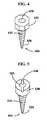
- FIGS. 4 and 5show two such arch bar fasteners, 400, 500.
- the arch bar fastener 400, 450is a bone screw having a threaded shaft 410, 460, a tip 420, 470 and a head 430, 480.
- the bone screwsmay be inserted into a bone such as a maxilla or mandible via a pilot hole that was previously drilled, or the bone screws self-drilling or self-tapping.
- the head of the arch bar fastener 400, 500is a compound head.
- compound headrefers to a screw head having a variety of functions.
- the head 430may be a shaped head such as a hexhead for using a driving tool to turn the arch bar fastener into bone.
- the hexhead shown in FIG. 4is for illustration only, as the shape of the head 430, 530 could be of any shape known to those of skill in the art for engaging a driver for the screw.
- the headcould be oval, triangular, square, pentagonal, or other such shape as are known to those of skill in the art.
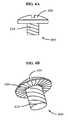
- the head 530may have a slotted drive mechanism 540 for engaging a slotted screwdriver to drive the arch bar fastener 500 into bone.
- the slotted drive mechanism 540is shown only as an example, as the alternative drive mechanism may be able to be engaged by a Phillips driver, a star driver, an Allen wrench, or other driver or wrench known to those of skill in the art.
- the compound head 400, 500is also configured to receive a secondary fastener that may be inserted through the slot 120, 220 in the arch bar 100, 200 to secure the arch bar 100, 200 to the arch bar fastener 400, 500, once the arch bar fastener 400, 500 has been engaged in a bone or prosthedontic apparatus.
- the secondary fasteneris a set screw 600 as shown in FIG. 6 .
- the compound head 400, 500may have a threaded bore 450, 550 to receive such a set screw 600.
- the secondary fastenermay be a rivet, nail, bayonet-style fastener, or other fastener known to those of skill in the art.
- the compound head 400, 500has a bore to receive such a rivet or nail, a complementary bayonet-style receiver to receive the bayonet-style fastener, or other receiver known to those of skill in the art.
- the set screw 600has a threaded shaft 610, a head 620, and a seating face 630.
- the head 620has a drive mechanism known to those of skill in the art and may include, but is not limited to, a slot drive, a Phillips drive, a hexhead for driving by a ratchet driver, an Allen head drive, or a star drive.
- the seating face 630 of the head 620may have a roughened surface to prevent, or at least reduce, unintended "turn-out" of the set screw 600 from the arch bar fastener 400, 500.
- an area around the slot 120, 220, on an outer face of the bar 110, 210may also be roughened to complement the roughened surface of the seating face 630 of the set screw 600, and provide additional resistance to "turn-out" of the set screw.
- a plurality of hooks 130, 230are attached to the bar 110, 210.
- pluralitymay mean one, but typically means more than one, such as two, three, four, five, six, seven, eight, nine, ten, eleven, twelve, thirteen, fourteen, fifteen, sixteen, seventeen, eighteen, nineteen, or twenty.
- the hooks 130, 220 on the arch bar 100, 200are used to attach a wire, an elastic such as a rubber band, or other device known to those of skill in the art, to the bar 110, 210 to immobilize, stabilize, or fixate the maxilla to the mandible, thus allowing for healing of the respective bones.
- the hooks 130, 230may be integrally formed with the bar 110, 210 such that they are all formed at the same time and of the same material.
- the hooks 130, 230are threaded on one end and threaded apertures or depressions, capable of receiving the hooks are included in the bar 110, 210.
- the hooks 130, 230may be positioned on the arch bar 100 such that the opening of the hook is toward an edge of the bar 110, 210, or toward the slots 120, 220 in the bar.
- the size, shape, and configuration of the hooksmay vary according to design preferences. The only limiting feature of the size, shape, and configuration of the hooks 130, 230 is that they must have the ability to satisfactorily allow placement of wire, elastic, or other fasteners to the arch bar 100, 200.
- the arch bars, hooks, and assorted fastenersmay be made from any of a variety of materials known to those of skill in the art. For example, they may be fabricated from stainless steel, titanium, other metals; acrylics; and/or other polymers.
- the arch bar fasteners 400, 500To secure the arch bar to the maxilla or the mandible, insertion of the arch bar fasteners 400, 500 into a root should be avoided. In fact, it is desired that the arch bar fasteners 400, 500 are inserted into the bone at positions between the roots of adjacent teeth.
- FIG. 7shows a perspective view of an arch bar fastener 400, 500 in place in a maxilla or mandible 715 and between the roots 725, 735 of the teeth.
- the slots 120, 220then allow for placement and movement of the bar 110, 210 to the desired position prior to fixing the arch bar 100, 200 in place via the set screw 600.
- a medical apparatushas two arch bars, as shown in FIG. 8 .
- a first arch bar 800is attached to the maxilla and a second arch bar 900 is attached to a mandible.
- the arch bars 800, 900are attached in the same manner as above, i.e. with set screws 850, 950 through the slots 820, 920.
- the hooks on each of the arch bars 800, 900are opposed to one another so that the securing wires, elastics such as rubber bands, or other attachment devices can be hooked to the arch bars 800, 900.
- the securing wires or other attachment devicesmay be separate entities, or a single wire may be intricately woven to attach the first arch bar 800 to the second arch bar 900, thus fixating the maxilla to the mandible.
- the medical apparatus disclosed hereinmay be used for stabilizing a mandibular arch or a maxillary arch .
- the arch barmay be bent to approximate the mandibular arch or the maxillary arch of a patient in need of stabilization or fixation of the mandibular and/or maxillary arch.
- Arch bar fastenersare secured into the mandible, maxilla, or a prosthedontic device. Either the bending of the arch bar or the securing of the arch bar fasteners may occur first in the sequence, however, the slots in the arch bar may be used to aid in the proper positioning of the arch bar fasteners.
- the arch bar fastenersshould approximately lie in a single plane as the slots in a bent arch bar will approximate a single plane.
- the arch barsmay be used to reduce a fracture of the mandible or maxilla.
- arch bar fastenersare inserted into a fractured mandible or maxilla.
- the fracturehas either been reduced or partially reduced to reform the natural mandibulary arch or maxillary arch.
- An arch baris then set in place over the arch bar fasteners and set screws are set in place such that the arch bar is able to move along the set screws via the slots. Once the surgeon, dentist, or other medical professional fully reduces the fracture, or approves of the reduced fracture, the set screws are tightened. The arch bar is then capable of maintaining the positioning of the reduced fracture. Once set in place, the arch bar keeps the fracture reduced for healing.
- a wire, an elastic, or other flexible or semi-rigid materialmay be secured between the hooks of the mandibular arch bar and the hooks of the maxillary arch bar. This may be done to establish intermaxillary fixation or dental occlusion. Such methods are known as wiring the jaws shut or intermaxillary fixation.
- the above described apparatusesare used to restore, fixate, or create anew dental occlusion between existing native dentition, dental implants, or other dental appliances, or for the treatment of fracture and/or reconstructing maxillary and/or mandibular reconstruction.
Landscapes
- Health & Medical Sciences (AREA)
- Orthopedic Medicine & Surgery (AREA)
- Life Sciences & Earth Sciences (AREA)
- Surgery (AREA)
- Medical Informatics (AREA)
- Engineering & Computer Science (AREA)
- Biomedical Technology (AREA)
- Heart & Thoracic Surgery (AREA)
- Nuclear Medicine, Radiotherapy & Molecular Imaging (AREA)
- Molecular Biology (AREA)
- Animal Behavior & Ethology (AREA)
- General Health & Medical Sciences (AREA)
- Public Health (AREA)
- Veterinary Medicine (AREA)
- Surgical Instruments (AREA)
- Dental Tools And Instruments Or Auxiliary Dental Instruments (AREA)
Description
- The invention is generally related to maxillofacial/dental devices. More specifically, the invention is related to devices for maxillary and/or mandibular fixation and/or stabilization.
- The fixation or stabilization of the upper and lower dental occlusal arches to one another is known as intermaxillary fixation (IMF), also known as maxillo-mandibular fixation (MMF). IMF has historically been a necessity in the treatment of all reconstructive jaw procedures.
- The earliest methods for providing IMF consisted of wiring techniques, in which metallic wires were placed around one or more (adjacent) teeth at their base(s) and were then twisted down to the teeth in a secure manner. When a wire is passed around a tooth (or teeth) at the base in such a way, it may be termed a circumdental wire ligature (CWL). Multiple CWL's can be placed along the span of the dental arch in a series, or the wire may also be fashioned such that a single continuous strand incorporates multiple teeth along the arch securely. In whatever manner this is accomplished, both upper and lower arches are so treated, and subsequently the jaws are then secured to one another with wire loops or elastics incorporating single or multiple CWLs on the opposing jaws, thus accomplishing IMF.
- Arch bars (or arch wires) are known to those of skill in the art. Arch bars involve the use of a linear metal bar or wire that may be applied and secured to the dental arch form. Arch bars typically have a plurality of hooks/tabs facing in a single direction. The arch bars and their corresponding hooks are placed in opposing directions for the upper and lower jaws so that wire loops or elastics could securely affix the jaws together. Arch bars typically impart stability to one or both the maxillary or mandibular arch. The relatively rigid bar spanning along the dental arch provides stability along the upper border of either jaw even when a fracture is present between teeth. A plurality of hooks allows placement of elastics or wire loops between the jaws at varying angles to potentially affect varying, advantageous tension vectors. The two common methods of securing all arch bars are (1) via CWL placed around the teeth in routine fashion but incorporating the arch bar; and (2) via orthodontic adhesives of a variety of types
- However, both methods suffer drawbacks. For example, the most common means to secure arch bars is via multiple circumdental wire ligatures. This is a time-consuming process, associated with significant discomfort and potential for dental injury. The wire ligatures themselves are uncomfortable and often must be adjusted/tightened by the treating physician. Removal of arch bars applied using CWL's, is equally uncomfortable, and there is further potential for dental injury. In addition, in some CWL's require removal under operative anesthesia, with the associated risks of anesthesia.
- While orthodontic adhesives are known, they too have disadvantages, in large part due to the conditions under which IMF is performed. For example, IMF is often performed by a surgical specialist, who is unfamiliar with the techniques and procedures used by orthodontists and dentists in the area of dental adhesives. The procedures are also, many times, conducted in a trauma setting where damage and blood loss limit the ability to work with such adhesives - which require a relatively clean, dry field for efficacy.
- Adhesive techniques and circumdental wiring techniques both require adequate dentition. Both techniques may be severely limited or even precluded in conditions for dental injury, loss, or preexisting poor dental health.
- Another method of IMF utilizes individual screws, placed in the bone between tooth roots, with a portion of the screw projecting external to the gingival or mucosa. Two or more IMF screws are typically placed into each of the upper and lower jaws. A wire loop is then either wrapped around the exposed portion of two opposing screws, or through a hole that is drilled through each of the two opposing screw heads, to provide IMF.
- The advantages of IMF screw fixation include speed of placement and comfort. The screws rarely require adjustment, are well-tolerated, and are easily removed. However, IMF screws do not provide stability along the dental arch as does an arch bar. Ideally, IMF is used not only for immobilization, but also for accurate restoration of occlusion. For fractures occurring between teeth, IMF screws do not provide upper border stabilization nor flexible technical application methods to optimize occlusion. Finally, it is difficult (if not impossible) to apply elastics between IMF screws. Elastic IMF is safer than wiring the jaws together, and is often preferred for specific fracture types in which the surgeon would prefer the patient to have guided mobility of the jaws rather than relative immobilization.
- Most of the technologies proposed for IMF technologies to date have been developed by orthodontists and oral surgeons. These dental specialists have been understandably inclined to consider only methods which involve fixation to teeth, a concept that has been historically accepted and perpetuated since the early 1900's. The most significant developments in reconstructive jaw surgery in the modern era have focused largely on methods for internal fixation (plating), rather than IMF. However, internal fixation is not a replacement for IMF, nor does is preclude the need for IMF in most cases, which is still a mandatory procedure for reconstruction of the dental arches.
US6257884 discloses a maxillomandibular fixation apparatus for locking teeth of the lower jaw and/or teeth of the upper jaw together to allow a fractured maxilla or mandible to heal. The apparatus includes a flexible arcuate arch bar that is positionable on the interior side of the teeth of a fractured jaw. A plurality of flexible receptacle segments are anchored onto the interior arch bar and include arms positioned to project from the arch bar between the teeth of the upper or lower jaws. Each segment arm includes a distal end that extends outward from each side of respective teeth towards the patient's cheeks. A separate exterior receiving bar can be aligned around the exterior surfaces of the teeth, the exterior receiving bar having holes therethrough for insertion of the distal ends of the segment arms. A plurality of lug nuts can be fastenable to the distal ends, clamping the exterior receiving bar against the exterior side of the teeth, and drawing wight the interior arch bar against the inside of the teeth. During wear, the lug nuts can be adjusted to change the distance between exterior and interior arch bars. The exterior lug nuts form an junction exterior to the teeth onto which ligature wire or elastic bands can be connected between upper and lower exterior receiving bars attached to upper and lower interior arch bars, to fixate the mandible and maxilla teeth and jaws together for healing.- Despite early developments in dental arch fixation technology, and advanced developments in other dental areas, there is currently no way to anchor existing arch bars to bone or other prosthetic dental devices using existing technologies.
- In one aspect, a medical apparatus is provided comprising:
- a bar, and
- a plurality of arch bar fasteners, each arch bar fastener comprising a bone screw comprising a threaded shaft and a head;
- wherein the bar is an arch bar that is configured to be attached, via the plurality of arch bar fasteners, to a mandible, a maxilla, or a prosthedontic apparatus;
- characterized in that the bar comprises:
- an elongated slot extending laterally along the bar; and
- a plurality of hooks.
- In some embodiments, each head may be a compound head, the compound head comprising a threaded bore configured to receive a set screw, the set screw being inserted through the elongated slot and screwed into the threaded bore. In such embodiments, the set screw comprises a threaded shaft, a head, and a seating face, wherein the seating face comprises a roughened surface.
- In some embodiments, the bar further comprises a roughened area on a face of the bar, adjacent to the slot, and configured to engage a set screw comprising a threaded shaft, a head, and a seating face, wherein the seating face comprises a roughened surface. In yet other embodiments, the slot is segmented by a plurality of lateral supports to form a plurality of slots. In yet further embodiments, the hooks are capable of receiving a wire or an elastic material, or other flexible, rigid, or semi-rigid material. In some embodiments, the bar is a bendable bar.
- In another aspect, the arch bar (110, 210) is bent to approximate the mandibular arch or the maxillary arch. The medical apparatus of the present invention may be used to stabilize a mandibular arch or a maxillary arch.
- In another aspect, the medical apparatus of the present invention may be used to reduce a fracture in a mandible or maxilla
- In another aspect, a medical apparatus is provided comprising: a first arch bar; and a second arch bar, wherein, the first arch bar is configured to be attached to a subject's maxilla with a plurality of arch bar fasteners; the second arch bar is configured to be attached to a subject's mandible with a plurality of arch bar fasteners; and the first arch bar is attached to the second arch bar via a wire, an elastic, or other flexible, rigid, or semi-rigid material.
- In another aspect, a medical apparatus is provided comprising:
- a first arch bar: and
- a second arch bar;
- each arch bar as described herein, wherein:
- the first arch bar is configured to be attached to a subject's maxilla with a plurality of arch bar fasteners;
- the second arch bar is configured to be attached to a subject's mandible with a plurality of arch bar fasteners; and
- the first arch bar is attached to the second arch bar via a wire, an elastic, or other flexible, rigid, or semi-rigid material.
- In some embodiments, the medical apparatus is capable of restoring or creating dental occlusion between existing native dentition, dental implants, or other dental appliances.
- In some embodiments, the first arch bar bends to approximate the maxillary arch;
the second arch bar bends to approximate the mandibulary arch. - In such embodiments, each arch bar fastener may comprise a bone screw comprising a threaded shaft and a compound head, the compound head comprising a threaded bore configured to receive a set screw;
the plurality of set screws are inserted through the elongated slot; and
the plurality of set screws screw into the threaded bores. - In some such embodiments, a method of using the invention comprises applying a fastener to the hooks of the first arch bar and to the hooks of the second arch bar to enact intermaxillary fixation, and/or establish dental occlusion. In other such embodiments, the fastener may be a wire, an elastic, or other flexible, or semi-rigid material.
FIG. 1 is a frontal view of an arch bar according to one embodiment of the invention.FIG. 2 is a frontal view of an arch bar according to one embodiment of the invention.FIG. 3 is a top view of an arch bar bent to approximate a mandibulary or maxillary arch, according to one embodiment.FIG. 4 is a perspective view of an arch bar fastener, according to one embodiment.FIG. 5 is a perspective view of an arch bar fastener, according to one embodiment.FIGS. 6A and 6B are two perspective views of a set screw, according to one embodiment.FIG. 7 is a perspective view of the attachment of an arch bar to a maxilla or mandible using an arch bar fastener and set screw, according to one embodiment.FIG. 8 is a panorex view of a dental arch with two arch bars, according to one embodiment.- Arch bars are medical apparatuses for providing stabilization and/or fixation of the mandible or the maxilla, or between the mandible and maxilla. Such medical apparatuses may be used for a number of medical needs such as, but not limited to, treatment of fracture, restoration and fixation of dental occlusion, and maxillary and/or mandibular reconstruction with or without bone grafts. The arch bars may be affixed to bone or prosthedontic devices, thus precluding the need for CWLs, or the use of adhesives.
- As shown in
FIG. 1 , anarch bar 100 is abar 110 having aslot 120, and a plurality ofhooks 130. Theslot 120 is defined bylateral supports 140 of thebar 110. Such lateral supports 140 provide rigidity to thebar 110 around theslot 120. Theslot 120 is configured to receive a setting fixture, or a plurality of setting fixtures for securing thearch bar 100 to bone such a mandible or maxilla, or to a prosthedontic apparatus. - As shown in
FIG. 2 , and according to one embodiment, anarch bar 200 is abar 210 having a plurality ofslots 220, and a plurality ofhooks 230. The plurality ofslots 220 may be two slots, three slots as shown inFIG. 2 , four slots, five slots, or more. The application desired will determine the number of slots provided in thearch bar 220. Theslots 220 are defined by a plurality of lateral supports 240. Such lateral supports 240 provide rigidity to thebar 210 around theslots 220. Theslots 220 are configured to receive a plurality of setting fixtures for securing thearch bar 100 to bone such a mandible or maxilla, or to a prosthedontic apparatus. - The bars may be either bendable or not bendable. Bending can facilitate the surgeon or medical professional's ability to approximate a maxillary or mandibular arch, as shown in
FIG. 3 . As used herein, the term "bendable" is to mean that the item to which the term refers, may be moved or shaped, in response to the application of an external force. Further, once moved or bent, the item does not return to its previous position, without being acted upon by a second external force. In other words, the item is bent and stays bent, until bent into another shape or position. - The arch bars may also not be bendable, instead being preformed to a rigid arch position upon manufacture, then resist bending to a new position, or which would then return to the preformed position upon attempted bending. As used herein, the term "rigid" is used to refer to an item that resists bending to a moderate force, but may be bent under extreme force as compared to a bendable item.
- The
slots bar FIGS. 4 and 5 show two such arch bar fasteners, 400, 500. In each ofFIGS. 4 and 5 , thearch bar fastener shaft 410, 460, atip 420, 470 and ahead 430, 480. The bone screws may be inserted into a bone such as a maxilla or mandible via a pilot hole that was previously drilled, or the bone screws self-drilling or self-tapping. - The head of the
arch bar fastener FIG. 4 , thehead 430 may be a shaped head such as a hexhead for using a driving tool to turn the arch bar fastener into bone. The hexhead shown inFIG. 4 is for illustration only, as the shape of thehead FIG. 5 , thehead 530 may have a slotteddrive mechanism 540 for engaging a slotted screwdriver to drive thearch bar fastener 500 into bone. Again, the slotteddrive mechanism 540 is shown only as an example, as the alternative drive mechanism may be able to be engaged by a Phillips driver, a star driver, an Allen wrench, or other driver or wrench known to those of skill in the art. - The
compound head slot arch bar arch bar arch bar fastener arch bar fastener set screw 600 as shown inFIG. 6 . As such, thecompound head bore set screw 600. In other embodiments, the secondary fastener may be a rivet, nail, bayonet-style fastener, or other fastener known to those of skill in the art. In such embodiments, thecompound head - The
set screw 600, as described in some embodiments, has a threadedshaft 610, ahead 620, and aseating face 630. Thehead 620 has a drive mechanism known to those of skill in the art and may include, but is not limited to, a slot drive, a Phillips drive, a hexhead for driving by a ratchet driver, an Allen head drive, or a star drive. Theseating face 630 of thehead 620 may have a roughened surface to prevent, or at least reduce, unintended "turn-out" of theset screw 600 from thearch bar fastener slot bar seating face 630 of theset screw 600, and provide additional resistance to "turn-out" of the set screw. - As noted above, a plurality of
hooks bar hooks arch bar bar - The
hooks bar hooks bar - The
hooks arch bar 100 such that the opening of the hook is toward an edge of thebar slots hooks arch bar - The arch bars, hooks, and assorted fasteners may be made from any of a variety of materials known to those of skill in the art. For example, they may be fabricated from stainless steel, titanium, other metals; acrylics; and/or other polymers.
- To secure the arch bar to the maxilla or the mandible, insertion of the
arch bar fasteners arch bar fasteners FIG. 7 shows a perspective view of anarch bar fastener mandible 715 and between theroots slots bar arch bar set screw 600.- In some aspects, a medical apparatus has two arch bars, as shown in
FIG. 8 . A firstarch bar 800 is attached to the maxilla and a secondarch bar 900 is attached to a mandible. The arch bars 800, 900 are attached in the same manner as above, i.e. with setscrews slots arch bars arch bars arch bar 800 to the secondarch bar 900, thus fixating the maxilla to the mandible. - In another aspect, the medical apparatus disclosed herein may be used for stabilizing a mandibular arch or a maxillary arch . For example, the arch bar may be bent to approximate the mandibular arch or the maxillary arch of a patient in need of stabilization or fixation of the mandibular and/or maxillary arch. Arch bar fasteners are secured into the mandible, maxilla, or a prosthedontic device. Either the bending of the arch bar or the securing of the arch bar fasteners may occur first in the sequence, however, the slots in the arch bar may be used to aid in the proper positioning of the arch bar fasteners. For example, the arch bar fasteners should approximately lie in a single plane as the slots in a bent arch bar will approximate a single plane.
- In another aspect, the arch bars may be used to reduce a fracture of the mandible or maxilla. In such embodiments, arch bar fasteners are inserted into a fractured mandible or maxilla. In some embodiments, the fracture has either been reduced or partially reduced to reform the natural mandibulary arch or maxillary arch. An arch bar is then set in place over the arch bar fasteners and set screws are set in place such that the arch bar is able to move along the set screws via the slots. Once the surgeon, dentist, or other medical professional fully reduces the fracture, or approves of the reduced fracture, the set screws are tightened. The arch bar is then capable of maintaining the positioning of the reduced fracture. Once set in place, the arch bar keeps the fracture reduced for healing.
- In other embodiments, where both a mandibular and a maxillary arch bar are used, a wire, an elastic, or other flexible or semi-rigid material may be secured between the hooks of the mandibular arch bar and the hooks of the maxillary arch bar. This may be done to establish intermaxillary fixation or dental occlusion. Such methods are known as wiring the jaws shut or intermaxillary fixation.
- The embodiments illustratively described herein may suitably be practiced in the absence of any element or elements, limitation or limitations, not specifically disclosed herein. Thus, for example, the terms "comprising," "including," "containing," etc. shall be read expansively and without limitation. Additionally, the terms and expressions employed herein have been used as terms of description and not of limitation, and there is no intention in the use of such terms and expressions of excluding any equivalents of the features shown and described or portions thereof, but it is recognized that various modifications are possible within the scope of the invention claimed. Additionally the phrase "consisting essentially of" will be understood to include those elements specifically recited and those additional elements that do not materially affect the basic and novel characteristics of the claimed invention. The phrase "consisting of" excludes any element not specifically specified.
- The above described apparatuses are used to restore, fixate, or create anew dental occlusion between existing native dentition, dental implants, or other dental appliances, or for the treatment of fracture and/or reconstructing maxillary and/or mandibular reconstruction.
- The present invention, thus generally described, it should be understood that changes and modifications can be made therein in accordance with ordinary skill in the art without departing from the invention in its broader aspects as defined in the following claims.
Claims (12)
- A medical apparatus comprising:a bar (110, 210), anda plurality of arch bar fasteners (400, 500), each arch bar fastener (400, 500) comprising a bone screw comprising a threaded shaft (410, 460) and a head (430, 480);wherein the bar (110, 210) is an arch bar that is configured to be attached, via the plurality of arch bar fasteners (400, 500), to a mandible, a maxilla, or a prosthedontic apparatus;characterized in that the bar (110, 210) comprises:an elongated slot (120, 220) extending laterally along the bar (110, 210); anda plurality of hooks (130, 230).
- The medical apparatus of Claim 1, wherein each head (430, 480) is a compound head, the compound head comprising a threaded bore (450, 550) configured to receive a set screw (600), the set screw (600) being inserted through the elongated slot (120, 220) and screwed into the threaded bore (450, 550).
- The medical apparatus of Claim 2, wherein the set screw (600) comprises a threaded shaft (610), a head (620), and a seating face (630), wherein the seating face (630) comprises a roughened surface.
- The medical apparatus of Claim 1, wherein the bar (110, 210) further comprises a roughened area on a face of the bar (110, 210), adjacent to the elongated slot (120, 220), and configured to engage a set screw (600) comprising a threaded shaft (610), a head (620), and a seating face (630), wherein the seating face (630) comprises a roughened surface.
- The medical apparatus of Claim 1, wherein the elongated slot (120, 220) is segmented by a plurality of lateral supports (140).
- The medical apparatus of Claim 1, wherein the hooks (130, 230) are capable of receiving a wire or an elastic material, or other flexible, rigid, or semi-rigid material.
- The medical apparatus of Claim 1, wherein the bar (110, 210) is a bendable bar.
- The medical apparatus of Claim 2, wherein the arch bar (110, 210) is bent to approximate the mandibular arch or the maxillary arch.
- A medical apparatus comprising:a first arch bar (800); anda second arch bar (900);each arch bar according to Claim 1, wherein:the first arch bar (800) is configured to be attached to a subject's maxilla with a plurality of arch bar fasteners (400, 500);the second arch bar (900) is configured to be attached to a subject's mandible with a plurality of arch bar fasteners (400, 500); andthe first arch bar (800) is attached to the second arch bar (900) via a wire, an elastic, or other flexible, rigid, or semi-rigid material.
- The medical apparatus of Claim 9, wherein:the first arch bar (800) bends to approximate the maxillary arch;the second arch bar (900) bends to approximate the mandibulary arch.
- The medical apparatus of Claim 10, wherein:each arch bar fastener (400, 500) comprises a bone screw comprising a threaded shaft (410, 460) and a compound head, the compound head comprising a threaded bore (450, 550) configured to receive a set screw (600);the plurality of set screws (600) are inserted through the elongated slot (120, 220); andthe plurality of set screws (600) screw into the threaded bores (450, 550).
- The medical apparatus of any of Claims 9 to 11, wherein the hooks (130, 230) on each of the arch bars are opposed to one another.
Applications Claiming Priority (2)
| Application Number | Priority Date | Filing Date | Title |
|---|---|---|---|
| US1786107P | 2007-12-31 | 2007-12-31 | |
| PCT/US2008/085680WO2009085560A1 (en) | 2007-12-31 | 2008-12-05 | Intermaxillary fixation device and method of using same |
Publications (3)
| Publication Number | Publication Date |
|---|---|
| EP2237735A1 EP2237735A1 (en) | 2010-10-13 |
| EP2237735A4 EP2237735A4 (en) | 2013-08-21 |
| EP2237735B1true EP2237735B1 (en) | 2015-10-07 |
Family
ID=40798899
Family Applications (1)
| Application Number | Title | Priority Date | Filing Date |
|---|---|---|---|
| EP08868823.9AActiveEP2237735B1 (en) | 2007-12-31 | 2008-12-05 | Intermaxillary fixation device |
Country Status (4)
| Country | Link |
|---|---|
| US (5) | US10010347B2 (en) |
| EP (1) | EP2237735B1 (en) |
| ES (1) | ES2550758T3 (en) |
| WO (1) | WO2009085560A1 (en) |
Families Citing this family (67)
| Publication number | Priority date | Publication date | Assignee | Title |
|---|---|---|---|---|
| US8108189B2 (en) | 2008-03-25 | 2012-01-31 | Align Technologies, Inc. | Reconstruction of non-visible part of tooth |
| US9492243B2 (en) | 2008-05-23 | 2016-11-15 | Align Technology, Inc. | Dental implant positioning |
| US8092215B2 (en) | 2008-05-23 | 2012-01-10 | Align Technology, Inc. | Smile designer |
| US8172569B2 (en) | 2008-06-12 | 2012-05-08 | Align Technology, Inc. | Dental appliance |
| US8292617B2 (en) | 2009-03-19 | 2012-10-23 | Align Technology, Inc. | Dental wire attachment |
| US8765031B2 (en) | 2009-08-13 | 2014-07-01 | Align Technology, Inc. | Method of forming a dental appliance |
| US8896592B2 (en) | 2009-08-21 | 2014-11-25 | Align Technology, Inc. | Digital dental modeling |
| RU2430698C2 (en)* | 2009-12-22 | 2011-10-10 | Константин Петрович Головко | Method of extrafocal nail osteosynthesis in guerin's (le fort) fractures and kit for implementation thereof |
| US9241774B2 (en) | 2010-04-30 | 2016-01-26 | Align Technology, Inc. | Patterned dental positioning appliance |
| US9211166B2 (en) | 2010-04-30 | 2015-12-15 | Align Technology, Inc. | Individualized orthodontic treatment index |
| US20120225398A1 (en)* | 2011-02-03 | 2012-09-06 | Ashin Al Fallah | Orthodontic Archwire And Bracket System |
| US9403238B2 (en) | 2011-09-21 | 2016-08-02 | Align Technology, Inc. | Laser cutting |
| US9375300B2 (en) | 2012-02-02 | 2016-06-28 | Align Technology, Inc. | Identifying forces on a tooth |
| US9433476B2 (en) | 2012-03-01 | 2016-09-06 | Align Technology, Inc. | Interproximal reduction planning |
| US9220580B2 (en) | 2012-03-01 | 2015-12-29 | Align Technology, Inc. | Determining a dental treatment difficulty |
| US9554936B2 (en) | 2012-05-07 | 2017-01-31 | Lawrence D. Singer | Singer-Domanski resin MMF/reimplantation device |
| US10070944B2 (en) | 2012-05-07 | 2018-09-11 | Lawrence D. Singer | Singer-domanski resin MMF/reimplantation device |
| WO2016079569A1 (en)* | 2014-11-20 | 2016-05-26 | Montejo Tarazona Javier | Bone fixation system |
| US20140288558A1 (en)* | 2013-03-19 | 2014-09-25 | Javier Montejo | Flexible Rail Bar Bone Fixation System |
| US9517087B2 (en) | 2013-03-19 | 2016-12-13 | Javier Montejo | Bone fixation system and methods |
| US9675427B2 (en)* | 2013-06-07 | 2017-06-13 | Align Technology, Inc. | Adjusting a tooth position |
| US8992582B1 (en) | 2013-08-26 | 2015-03-31 | Stryker Leibinger Gmbh & Co. Kg | Fixation devices and method |
| US10531900B2 (en) | 2014-04-17 | 2020-01-14 | Zimmer Biomet CMF and Thoracic, LLC | Contourable plate |
| US10449016B2 (en) | 2014-09-19 | 2019-10-22 | Align Technology, Inc. | Arch adjustment appliance |
| US9610141B2 (en) | 2014-09-19 | 2017-04-04 | Align Technology, Inc. | Arch expanding appliance |
| US10504386B2 (en) | 2015-01-27 | 2019-12-10 | Align Technology, Inc. | Training method and system for oral-cavity-imaging-and-modeling equipment |
| US10980585B2 (en)* | 2015-11-11 | 2021-04-20 | Jeffrey R. Marcus | Intermaxillary fixation device and method of using same |
| US11931222B2 (en) | 2015-11-12 | 2024-03-19 | Align Technology, Inc. | Dental attachment formation structures |
| US11554000B2 (en) | 2015-11-12 | 2023-01-17 | Align Technology, Inc. | Dental attachment formation structure |
| US11103330B2 (en) | 2015-12-09 | 2021-08-31 | Align Technology, Inc. | Dental attachment placement structure |
| US11596502B2 (en) | 2015-12-09 | 2023-03-07 | Align Technology, Inc. | Dental attachment placement structure |
| WO2017218947A1 (en) | 2016-06-17 | 2017-12-21 | Align Technology, Inc. | Intraoral appliances with sensing |
| US10383705B2 (en) | 2016-06-17 | 2019-08-20 | Align Technology, Inc. | Orthodontic appliance performance monitor |
| CA3030676A1 (en) | 2016-07-27 | 2018-02-01 | Align Technology, Inc. | Intraoral scanner with dental diagnostics capabilities |
| US10507087B2 (en) | 2016-07-27 | 2019-12-17 | Align Technology, Inc. | Methods and apparatuses for forming a three-dimensional volumetric model of a subject's teeth |
| CN117257492A (en) | 2016-11-04 | 2023-12-22 | 阿莱恩技术有限公司 | Method and apparatus for dental imaging |
| WO2018102770A1 (en) | 2016-12-02 | 2018-06-07 | Align Technology, Inc. | Force control, stop mechanism, regulating structure of removable arch adjustment appliance |
| US11026831B2 (en) | 2016-12-02 | 2021-06-08 | Align Technology, Inc. | Dental appliance features for speech enhancement |
| EP3547952B1 (en) | 2016-12-02 | 2020-11-04 | Align Technology, Inc. | Palatal expander |
| AU2017366755B2 (en) | 2016-12-02 | 2022-07-28 | Align Technology, Inc. | Methods and apparatuses for customizing rapid palatal expanders using digital models |
| US10548700B2 (en) | 2016-12-16 | 2020-02-04 | Align Technology, Inc. | Dental appliance etch template |
| US11547536B2 (en)* | 2017-01-19 | 2023-01-10 | Yasuhiro Itsuki | Base member for orthodontic implant device |
| ES2992791T3 (en)* | 2017-02-07 | 2024-12-18 | Kls Martin L P | Maxillomandibular fixation devices |
| US10779718B2 (en) | 2017-02-13 | 2020-09-22 | Align Technology, Inc. | Cheek retractor and mobile device holder |
| WO2018183358A1 (en) | 2017-03-27 | 2018-10-04 | Align Technology, Inc. | Apparatuses and methods assisting in dental therapies |
| US10613515B2 (en) | 2017-03-31 | 2020-04-07 | Align Technology, Inc. | Orthodontic appliances including at least partially un-erupted teeth and method of forming them |
| US11045283B2 (en) | 2017-06-09 | 2021-06-29 | Align Technology, Inc. | Palatal expander with skeletal anchorage devices |
| US10639134B2 (en) | 2017-06-26 | 2020-05-05 | Align Technology, Inc. | Biosensor performance indicator for intraoral appliances |
| US10885521B2 (en) | 2017-07-17 | 2021-01-05 | Align Technology, Inc. | Method and apparatuses for interactive ordering of dental aligners |
| CN111107806B (en) | 2017-07-21 | 2022-04-19 | 阿莱恩技术有限公司 | Jaw profile anchoring |
| CN110996842B (en) | 2017-07-27 | 2022-10-14 | 阿莱恩技术有限公司 | Tooth Staining, Transparency and Glazing |
| US12274597B2 (en) | 2017-08-11 | 2025-04-15 | Align Technology, Inc. | Dental attachment template tray systems |
| US11116605B2 (en) | 2017-08-15 | 2021-09-14 | Align Technology, Inc. | Buccal corridor assessment and computation |
| US11123156B2 (en) | 2017-08-17 | 2021-09-21 | Align Technology, Inc. | Dental appliance compliance monitoring |
| US12171575B2 (en) | 2017-10-04 | 2024-12-24 | Align Technology, Inc. | Intraoral systems and methods for sampling soft-tissue |
| US10813720B2 (en) | 2017-10-05 | 2020-10-27 | Align Technology, Inc. | Interproximal reduction templates |
| CN111565668B (en) | 2017-10-27 | 2022-06-07 | 阿莱恩技术有限公司 | Substitute occlusion adjusting structure |
| CN111295153B (en) | 2017-10-31 | 2023-06-16 | 阿莱恩技术有限公司 | Dental appliance with selective bite loading and controlled tip staggering |
| CN119235481A (en) | 2017-11-01 | 2025-01-03 | 阿莱恩技术有限公司 | Automatic treatment planning |
| US11534974B2 (en) | 2017-11-17 | 2022-12-27 | Align Technology, Inc. | Customized fabrication of orthodontic retainers based on patient anatomy |
| US11219506B2 (en) | 2017-11-30 | 2022-01-11 | Align Technology, Inc. | Sensors for monitoring oral appliances |
| US11432908B2 (en) | 2017-12-15 | 2022-09-06 | Align Technology, Inc. | Closed loop adaptive orthodontic treatment methods and apparatuses |
| US10980613B2 (en) | 2017-12-29 | 2021-04-20 | Align Technology, Inc. | Augmented reality enhancements for dental practitioners |
| US10813727B2 (en) | 2018-01-26 | 2020-10-27 | Align Technology, Inc. | Diagnostic intraoral tracking |
| US11937991B2 (en) | 2018-03-27 | 2024-03-26 | Align Technology, Inc. | Dental attachment placement structure |
| EP3773320B1 (en) | 2018-04-11 | 2024-05-15 | Align Technology, Inc. | Releasable palatal expanders |
| RU2735258C1 (en)* | 2020-02-04 | 2020-10-29 | Федеральное государственное бюджетное образовательное учреждение дополнительного профессионального образования "Российская медицинская академия непрерывного профессионального образования" Министерства здравоохранения Российской Федерации (ФГБОУ ДПО РМАНПО Минздрава России) | Method for single-jaw splinting in lower jaw fractures |
Family Cites Families (68)
| Publication number | Priority date | Publication date | Assignee | Title |
|---|---|---|---|---|
| US83195A (en) | 1868-10-20 | Improved bracket and rack | ||
| US533745A (en) | 1895-02-05 | Sash-fastener | ||
| US49779A (en) | 1865-09-05 | John o | ||
| US592250A (en) | 1897-10-26 | Hat and clothes rack | ||
| US1638006A (en) | 1926-02-26 | 1927-08-09 | Jelenko & Co Inc J F | Fracture splint |
| US2481177A (en) | 1944-08-22 | 1949-09-06 | Benjamin F Tofflemire | Intraoral fracture reduction appliance |
| US2502902A (en)* | 1946-01-25 | 1950-04-04 | Benjamin F Tofflemire | Intraoral fracture and orthodontic appliance |
| US2580821A (en)* | 1950-10-21 | 1952-01-01 | Nicola Toufick | Spring impactor bone plate |
| US2805777A (en)* | 1952-07-02 | 1957-09-10 | Charles O Larson | Tool holder |
| US3474779A (en) | 1967-03-10 | 1969-10-28 | William H Wall Jr | Dental arch bar for treating fractures |
| GB1231425A (en) | 1967-11-23 | 1971-05-12 | ||
| US4108313A (en)* | 1977-05-12 | 1978-08-22 | Bogar Jr Earl M | Vehicle mounted gun rack with mounting brackets |
| US4202328A (en) | 1977-11-23 | 1980-05-13 | Sukkarie Ghassan A | Method and means for fixation and immobilization of the jaws |
| US4230104A (en) | 1978-01-23 | 1980-10-28 | Richter Alice E | Splints for treating jaw fractures |
| US4372450A (en)* | 1981-12-07 | 1983-02-08 | Basic Line, Inc. | Hanging racks |
| US4639219A (en) | 1982-02-22 | 1987-01-27 | American Orthodontics Corporation | Surgical ball hooks |
| US4797095A (en) | 1984-05-11 | 1989-01-10 | Unitek Corporation | Orthodontic hook mounting |
| US4904188A (en) | 1988-05-20 | 1990-02-27 | Harold Baurmash | Direct bonded arch bar for maxillo-mandibular injuries |
| DE3943098C2 (en) | 1989-12-27 | 1997-01-23 | Krenkel Christian | Establishment or regulation of the mutual position of teeth |
| US5137158A (en) | 1991-07-01 | 1992-08-11 | Brockway Ronald L | Article support apparatus |
| US5842856A (en) | 1994-07-12 | 1998-12-01 | Casey; Kevin M. | Release system for treatment of a broken jaw |
| JP3566967B2 (en)* | 1995-07-03 | 2004-09-15 | ジンテーズ アクチエンゲゼルシャフト クール | Bone fragment fixation device |
| FR2738477B1 (en)* | 1995-09-11 | 1998-01-09 | Landanger Landos | IMPROVEMENT ON IMPLANTABLE PLATES IN MAXILLOFACIAL SURGERY |
| US5839899A (en)* | 1996-03-01 | 1998-11-24 | Robinson; Dane Q. | Method and apparatus for growing jaw bone utilizing a guided-tissue regeneration plate support and fixation system |
| SE506849C2 (en)* | 1996-06-27 | 1998-02-16 | Medevelop Ab | For implantation in bone tissue intended for fixture, prosthetic anchoring device and prosthesis |
| US6139550A (en)* | 1997-02-11 | 2000-10-31 | Michelson; Gary K. | Skeletal plating system |
| FR2760631B1 (en) | 1997-03-12 | 1999-10-29 | Xavier Calvez | MULTIPURPOSE MANDIBULAR PROPELLING TELESCOPIC CONNECTING RODS |
| DE29710860U1 (en) | 1997-06-23 | 1997-10-23 | MONDEAL Medical Systems GmbH, 78532 Tuttlingen | Intermaxillary fixation system |
| US5853092A (en) | 1997-08-28 | 1998-12-29 | Goodman; Gregory L. | Self-adapting tool rack |
| US6120288A (en) | 1997-09-25 | 2000-09-19 | Deslauriers; Richard J. | Device and method for mandibular fixation |
| JP3869543B2 (en) | 1997-12-05 | 2007-01-17 | デンツプライ三金株式会社 | Orthodontic support |
| US6086365A (en) | 1998-02-02 | 2000-07-11 | Walter Lorenz Surgical, Inc. | Bonded intermaxillary fixation splint |
| US6669697B1 (en)* | 1998-09-25 | 2003-12-30 | Perumala Corporation | Self-retaining bolt for internal spinal stabilizers |
| DE19859503A1 (en) | 1998-12-22 | 2000-07-06 | Georg Risse | Arch for orthodontics |
| AU3954200A (en) | 1999-05-03 | 2000-11-17 | Medartis Ag | Blockable bone plate |
| US6257884B1 (en) | 1999-10-14 | 2001-07-10 | Peter Chang | Maxillomandibular fixation device |
| US6227861B1 (en) | 2000-02-29 | 2001-05-08 | Richard G. Cartledge | Preformed mandibular splint |
| US6293949B1 (en) | 2000-03-01 | 2001-09-25 | Sdgi Holdings, Inc. | Superelastic spinal stabilization system and method |
| DE20007908U1 (en) | 2000-05-03 | 2000-12-21 | Medartis Ag, Basel | Contoured bone plate |
| US6872210B2 (en) | 2001-02-23 | 2005-03-29 | James P. Hearn | Sternum fixation device |
| US6827574B2 (en) | 2001-04-12 | 2004-12-07 | Kevin L. Payton | Skeletal transmucosal orthodontic plate and method |
| US7537604B2 (en)* | 2002-11-19 | 2009-05-26 | Acumed Llc | Bone plates with slots |
| DE50208954D1 (en) | 2001-05-10 | 2007-01-25 | Roger Minoretti | DEVICE FOR ORTHODONTIC AND / OR SURGICAL PURPOSES |
| US6589250B2 (en) | 2001-11-20 | 2003-07-08 | Stephen A. Schendel | Maxillary distraction device |
| US20050090825A1 (en)* | 2002-02-15 | 2005-04-28 | Medartis Ag | Bone plate |
| US20030160552A1 (en)* | 2002-02-22 | 2003-08-28 | Bacho Brett W. | Stress relieving plate |
| US6685468B1 (en)* | 2002-08-21 | 2004-02-03 | Tp Orthodontics, Inc. | Bondable orthodontic appliance with a polymer resin bonding base |
| US6896514B2 (en) | 2003-02-20 | 2005-05-24 | John Devincenzo | Orthodontic implant |
| DE10317871B3 (en)* | 2003-04-17 | 2004-11-11 | Stryker Leibinger Gmbh & Co. Kg | Osteosynthesis device |
| USD533745S1 (en)* | 2003-09-16 | 2006-12-19 | Bradshaw International, Inc. | Adjustable merchandising hook bar |
| US8236034B2 (en)* | 2004-04-19 | 2012-08-07 | Globus Medical, Inc. | Bone fixation plate |
| US20050282115A1 (en) | 2004-06-22 | 2005-12-22 | Tewodros Gedebou | Maxillo-mandibular fixation system & method |
| DE102004046414B4 (en) | 2004-09-24 | 2006-10-12 | Stryker Leibinger Gmbh & Co. Kg | Surgical anchoring device |
| US20060078849A1 (en)* | 2004-10-12 | 2006-04-13 | Parks Cynthia D | Dental splint |
| US7351058B2 (en) | 2006-02-14 | 2008-04-01 | Frank Fore | Arch bar |
| US8246663B2 (en)* | 2006-04-10 | 2012-08-21 | Scott Lovald | Osteosynthesis plate, method of customizing same, and method for installing same |
| US7281923B1 (en) | 2006-05-01 | 2007-10-16 | John Devincenzo | Orthodontic anchor appliance |
| US20070259306A1 (en) | 2006-05-05 | 2007-11-08 | Osteomed L.P. | Orthodontic Plate and Method |
| US7806686B2 (en) | 2006-08-24 | 2010-10-05 | Toads Llc | Anchor apparatus and method for orthodontic appliances |
| US20080081315A1 (en)* | 2006-09-28 | 2008-04-03 | Kim Samuel S | Dr. Seoung Ho Lee's augmentation plates for stabilizing dental implant fixtures |
| US7909610B1 (en) | 2006-12-21 | 2011-03-22 | Amato Craniofacial Engineering, LLC | Computer-aided system of orthopedic surgery |
| US20090036889A1 (en) | 2007-07-30 | 2009-02-05 | Callender R Sam | Method and apparatus for treatment of sleep apnea |
| WO2009076207A1 (en) | 2007-12-10 | 2009-06-18 | Marcus Jeffrey R | Intermaxillary fixation device and method of using same |
| US8662889B2 (en) | 2008-08-27 | 2014-03-04 | Georgetown University | Arch bars for use in maxillofacial surgery and orthodontics |
| US9107716B2 (en) | 2009-11-23 | 2015-08-18 | DePuy Synthes Products, Inc. | Flexible maxillo-mandibular fixation device |
| US9554936B2 (en)* | 2012-05-07 | 2017-01-31 | Lawrence D. Singer | Singer-Domanski resin MMF/reimplantation device |
| US8992582B1 (en)* | 2013-08-26 | 2015-03-31 | Stryker Leibinger Gmbh & Co. Kg | Fixation devices and method |
| US9820777B2 (en)* | 2014-07-09 | 2017-11-21 | DePuy Synthes Products, Inc. | Flexible maxillo-mandibular fixation device |
- 2008
- 2008-12-05EPEP08868823.9Apatent/EP2237735B1/enactiveActive
- 2008-12-05ESES08868823.9Tpatent/ES2550758T3/enactiveActive
- 2008-12-05USUS12/329,306patent/US10010347B2/enactiveActive
- 2008-12-05WOPCT/US2008/085680patent/WO2009085560A1/enactiveApplication Filing
- 2018
- 2018-06-04USUS15/996,728patent/US10588665B2/enactiveActive
- 2020
- 2020-01-24USUS16/751,753patent/US11751911B2/enactiveActive
- 2023
- 2023-08-02USUS18/229,322patent/US12408948B2/enactiveActive
- 2025
- 2025-01-14USUS19/020,345patent/US20250213275A1/enactivePending
Also Published As
| Publication number | Publication date |
|---|---|
| EP2237735A1 (en) | 2010-10-13 |
| US20180271560A1 (en) | 2018-09-27 |
| ES2550758T3 (en) | 2015-11-12 |
| US20200155199A1 (en) | 2020-05-21 |
| WO2009085560A1 (en) | 2009-07-09 |
| US20090170050A1 (en) | 2009-07-02 |
| US10588665B2 (en) | 2020-03-17 |
| US20230371985A1 (en) | 2023-11-23 |
| US10010347B2 (en) | 2018-07-03 |
| US12408948B2 (en) | 2025-09-09 |
| EP2237735A4 (en) | 2013-08-21 |
| US20250213275A1 (en) | 2025-07-03 |
| US11751911B2 (en) | 2023-09-12 |
Similar Documents
| Publication | Publication Date | Title |
|---|---|---|
| US12408948B2 (en) | Intermaxillary fixation device and method of using same | |
| US12171475B2 (en) | Intermaxillary fixation device and method of using same | |
| US6827574B2 (en) | Skeletal transmucosal orthodontic plate and method | |
| US8662889B2 (en) | Arch bars for use in maxillofacial surgery and orthodontics | |
| US5885290A (en) | Intra-oral bone distraction device | |
| US8992582B1 (en) | Fixation devices and method | |
| US10980585B2 (en) | Intermaxillary fixation device and method of using same | |
| US20040197726A1 (en) | Clip type orthodontic anchor | |
| Özçırpıcı et al. | 13 Insertion and removal of orthodontic miniplates |
Legal Events
| Date | Code | Title | Description |
|---|---|---|---|
| PUAI | Public reference made under article 153(3) epc to a published international application that has entered the european phase | Free format text:ORIGINAL CODE: 0009012 | |
| 17P | Request for examination filed | Effective date:20100615 | |
| AK | Designated contracting states | Kind code of ref document:A1 Designated state(s):AT BE BG CH CY CZ DE DK EE ES FI FR GB GR HR HU IE IS IT LI LT LU LV MC MT NL NO PL PT RO SE SI SK TR | |
| AX | Request for extension of the european patent | Extension state:AL BA MK RS | |
| DAX | Request for extension of the european patent (deleted) | ||
| A4 | Supplementary search report drawn up and despatched | Effective date:20130722 | |
| RIC1 | Information provided on ipc code assigned before grant | Ipc:A61B 17/80 20060101ALI20130716BHEP Ipc:A61C 8/00 20060101ALI20130716BHEP Ipc:A61F 2/28 20060101ALI20130716BHEP Ipc:A61C 3/00 20060101AFI20130716BHEP Ipc:A61B 17/64 20060101ALI20130716BHEP | |
| 17Q | First examination report despatched | Effective date:20141103 | |
| GRAP | Despatch of communication of intention to grant a patent | Free format text:ORIGINAL CODE: EPIDOSNIGR1 | |
| INTG | Intention to grant announced | Effective date:20150430 | |
| GRAS | Grant fee paid | Free format text:ORIGINAL CODE: EPIDOSNIGR3 | |
| GRAA | (expected) grant | Free format text:ORIGINAL CODE: 0009210 | |
| AK | Designated contracting states | Kind code of ref document:B1 Designated state(s):AT BE BG CH CY CZ DE DK EE ES FI FR GB GR HR HU IE IS IT LI LT LU LV MC MT NL NO PL PT RO SE SI SK TR | |
| REG | Reference to a national code | Ref country code:GB Ref legal event code:FG4D | |
| REG | Reference to a national code | Ref country code:AT Ref legal event code:REF Ref document number:753244 Country of ref document:AT Kind code of ref document:T Effective date:20151015 Ref country code:CH Ref legal event code:EP | |
| REG | Reference to a national code | Ref country code:IE Ref legal event code:FG4D | |
| REG | Reference to a national code | Ref country code:FR Ref legal event code:PLFP Year of fee payment:8 | |
| REG | Reference to a national code | Ref country code:ES Ref legal event code:FG2A Ref document number:2550758 Country of ref document:ES Kind code of ref document:T3 Effective date:20151112 | |
| REG | Reference to a national code | Ref country code:CH Ref legal event code:PCOW Free format text:NEW ADDRESS: 117 WOODKIRK LANE CHAPEL HILL, NORTH CAROLINA 27514 (US) Ref country code:CH Ref legal event code:NV Representative=s name:MICHELI AND CIE SA, CH | |
| REG | Reference to a national code | Ref country code:DE Ref legal event code:R096 Ref document number:602008040583 Country of ref document:DE | |
| RAP2 | Party data changed (patent owner data changed or rights of a patent transferred) | Owner name:MARCUS, JEFFREY R. | |
| RIN2 | Information on inventor provided after grant (corrected) | Inventor name:MARCUS, JEFFREY R. | |
| REG | Reference to a national code | Ref country code:NL Ref legal event code:MP Effective date:20151007 | |
| REG | Reference to a national code | Ref country code:AT Ref legal event code:MK05 Ref document number:753244 Country of ref document:AT Kind code of ref document:T Effective date:20151007 | |
| REG | Reference to a national code | Ref country code:LT Ref legal event code:MG4D | |
| REG | Reference to a national code | Ref country code:CH Ref legal event code:PCOW | |
| PG25 | Lapsed in a contracting state [announced via postgrant information from national office to epo] | Ref country code:HR Free format text:LAPSE BECAUSE OF FAILURE TO SUBMIT A TRANSLATION OF THE DESCRIPTION OR TO PAY THE FEE WITHIN THE PRESCRIBED TIME-LIMIT Effective date:20151007 Ref country code:LT Free format text:LAPSE BECAUSE OF FAILURE TO SUBMIT A TRANSLATION OF THE DESCRIPTION OR TO PAY THE FEE WITHIN THE PRESCRIBED TIME-LIMIT Effective date:20151007 Ref country code:NO Free format text:LAPSE BECAUSE OF FAILURE TO SUBMIT A TRANSLATION OF THE DESCRIPTION OR TO PAY THE FEE WITHIN THE PRESCRIBED TIME-LIMIT Effective date:20160107 Ref country code:NL Free format text:LAPSE BECAUSE OF FAILURE TO SUBMIT A TRANSLATION OF THE DESCRIPTION OR TO PAY THE FEE WITHIN THE PRESCRIBED TIME-LIMIT Effective date:20151007 Ref country code:IS Free format text:LAPSE BECAUSE OF FAILURE TO SUBMIT A TRANSLATION OF THE DESCRIPTION OR TO PAY THE FEE WITHIN THE PRESCRIBED TIME-LIMIT Effective date:20160207 | |
| REG | Reference to a national code | Ref country code:DE Ref legal event code:R082 Ref document number:602008040583 Country of ref document:DE Representative=s name:HERNANDEZ, YORCK, DIPL.-ING., DE | |
| PG25 | Lapsed in a contracting state [announced via postgrant information from national office to epo] | Ref country code:BE Free format text:LAPSE BECAUSE OF NON-PAYMENT OF DUE FEES Effective date:20151231 Ref country code:LV Free format text:LAPSE BECAUSE OF FAILURE TO SUBMIT A TRANSLATION OF THE DESCRIPTION OR TO PAY THE FEE WITHIN THE PRESCRIBED TIME-LIMIT Effective date:20151007 Ref country code:PT Free format text:LAPSE BECAUSE OF FAILURE TO SUBMIT A TRANSLATION OF THE DESCRIPTION OR TO PAY THE FEE WITHIN THE PRESCRIBED TIME-LIMIT Effective date:20160208 Ref country code:FI Free format text:LAPSE BECAUSE OF FAILURE TO SUBMIT A TRANSLATION OF THE DESCRIPTION OR TO PAY THE FEE WITHIN THE PRESCRIBED TIME-LIMIT Effective date:20151007 Ref country code:GR Free format text:LAPSE BECAUSE OF FAILURE TO SUBMIT A TRANSLATION OF THE DESCRIPTION OR TO PAY THE FEE WITHIN THE PRESCRIBED TIME-LIMIT Effective date:20160108 Ref country code:AT Free format text:LAPSE BECAUSE OF FAILURE TO SUBMIT A TRANSLATION OF THE DESCRIPTION OR TO PAY THE FEE WITHIN THE PRESCRIBED TIME-LIMIT Effective date:20151007 Ref country code:SE Free format text:LAPSE BECAUSE OF FAILURE TO SUBMIT A TRANSLATION OF THE DESCRIPTION OR TO PAY THE FEE WITHIN THE PRESCRIBED TIME-LIMIT Effective date:20151007 Ref country code:PL Free format text:LAPSE BECAUSE OF FAILURE TO SUBMIT A TRANSLATION OF THE DESCRIPTION OR TO PAY THE FEE WITHIN THE PRESCRIBED TIME-LIMIT Effective date:20151007 | |
| REG | Reference to a national code | Ref country code:DE Ref legal event code:R097 Ref document number:602008040583 Country of ref document:DE | |
| RAP2 | Party data changed (patent owner data changed or rights of a patent transferred) | Owner name:MARCUS, JEFFREY R. | |
| RIN2 | Information on inventor provided after grant (corrected) | Inventor name:MARCUS, JEFFREY R. | |
| PG25 | Lapsed in a contracting state [announced via postgrant information from national office to epo] | Ref country code:LU Free format text:LAPSE BECAUSE OF FAILURE TO SUBMIT A TRANSLATION OF THE DESCRIPTION OR TO PAY THE FEE WITHIN THE PRESCRIBED TIME-LIMIT Effective date:20151205 Ref country code:CZ Free format text:LAPSE BECAUSE OF FAILURE TO SUBMIT A TRANSLATION OF THE DESCRIPTION OR TO PAY THE FEE WITHIN THE PRESCRIBED TIME-LIMIT Effective date:20151007 Ref country code:MC Free format text:LAPSE BECAUSE OF FAILURE TO SUBMIT A TRANSLATION OF THE DESCRIPTION OR TO PAY THE FEE WITHIN THE PRESCRIBED TIME-LIMIT Effective date:20151007 | |
| PLBE | No opposition filed within time limit | Free format text:ORIGINAL CODE: 0009261 | |
| STAA | Information on the status of an ep patent application or granted ep patent | Free format text:STATUS: NO OPPOSITION FILED WITHIN TIME LIMIT | |
| PG25 | Lapsed in a contracting state [announced via postgrant information from national office to epo] | Ref country code:SK Free format text:LAPSE BECAUSE OF FAILURE TO SUBMIT A TRANSLATION OF THE DESCRIPTION OR TO PAY THE FEE WITHIN THE PRESCRIBED TIME-LIMIT Effective date:20151007 Ref country code:RO Free format text:LAPSE BECAUSE OF FAILURE TO SUBMIT A TRANSLATION OF THE DESCRIPTION OR TO PAY THE FEE WITHIN THE PRESCRIBED TIME-LIMIT Effective date:20151007 Ref country code:EE Free format text:LAPSE BECAUSE OF FAILURE TO SUBMIT A TRANSLATION OF THE DESCRIPTION OR TO PAY THE FEE WITHIN THE PRESCRIBED TIME-LIMIT Effective date:20151007 Ref country code:DK Free format text:LAPSE BECAUSE OF FAILURE TO SUBMIT A TRANSLATION OF THE DESCRIPTION OR TO PAY THE FEE WITHIN THE PRESCRIBED TIME-LIMIT Effective date:20151007 | |
| 26N | No opposition filed | Effective date:20160708 | |
| REG | Reference to a national code | Ref country code:IE Ref legal event code:MM4A | |
| PG25 | Lapsed in a contracting state [announced via postgrant information from national office to epo] | Ref country code:IE Free format text:LAPSE BECAUSE OF NON-PAYMENT OF DUE FEES Effective date:20151205 | |
| REG | Reference to a national code | Ref country code:FR Ref legal event code:PLFP Year of fee payment:9 | |
| PG25 | Lapsed in a contracting state [announced via postgrant information from national office to epo] | Ref country code:SI Free format text:LAPSE BECAUSE OF FAILURE TO SUBMIT A TRANSLATION OF THE DESCRIPTION OR TO PAY THE FEE WITHIN THE PRESCRIBED TIME-LIMIT Effective date:20151007 | |
| PG25 | Lapsed in a contracting state [announced via postgrant information from national office to epo] | Ref country code:BE Free format text:LAPSE BECAUSE OF FAILURE TO SUBMIT A TRANSLATION OF THE DESCRIPTION OR TO PAY THE FEE WITHIN THE PRESCRIBED TIME-LIMIT Effective date:20151007 | |
| PG25 | Lapsed in a contracting state [announced via postgrant information from national office to epo] | Ref country code:BG Free format text:LAPSE BECAUSE OF FAILURE TO SUBMIT A TRANSLATION OF THE DESCRIPTION OR TO PAY THE FEE WITHIN THE PRESCRIBED TIME-LIMIT Effective date:20151007 Ref country code:HU Free format text:LAPSE BECAUSE OF FAILURE TO SUBMIT A TRANSLATION OF THE DESCRIPTION OR TO PAY THE FEE WITHIN THE PRESCRIBED TIME-LIMIT; INVALID AB INITIO Effective date:20081205 | |
| PG25 | Lapsed in a contracting state [announced via postgrant information from national office to epo] | Ref country code:CY Free format text:LAPSE BECAUSE OF FAILURE TO SUBMIT A TRANSLATION OF THE DESCRIPTION OR TO PAY THE FEE WITHIN THE PRESCRIBED TIME-LIMIT Effective date:20151007 | |
| PG25 | Lapsed in a contracting state [announced via postgrant information from national office to epo] | Ref country code:MT Free format text:LAPSE BECAUSE OF FAILURE TO SUBMIT A TRANSLATION OF THE DESCRIPTION OR TO PAY THE FEE WITHIN THE PRESCRIBED TIME-LIMIT Effective date:20151007 Ref country code:TR Free format text:LAPSE BECAUSE OF FAILURE TO SUBMIT A TRANSLATION OF THE DESCRIPTION OR TO PAY THE FEE WITHIN THE PRESCRIBED TIME-LIMIT Effective date:20151007 | |
| REG | Reference to a national code | Ref country code:FR Ref legal event code:PLFP Year of fee payment:10 | |
| P01 | Opt-out of the competence of the unified patent court (upc) registered | Effective date:20230522 | |
| PGFP | Annual fee paid to national office [announced via postgrant information from national office to epo] | Ref country code:DE Payment date:20241001 Year of fee payment:17 | |
| PGFP | Annual fee paid to national office [announced via postgrant information from national office to epo] | Ref country code:GB Payment date:20241001 Year of fee payment:17 | |
| PGFP | Annual fee paid to national office [announced via postgrant information from national office to epo] | Ref country code:FR Payment date:20241001 Year of fee payment:17 | |
| PGFP | Annual fee paid to national office [announced via postgrant information from national office to epo] | Ref country code:IT Payment date:20241112 Year of fee payment:17 | |
| PGFP | Annual fee paid to national office [announced via postgrant information from national office to epo] | Ref country code:ES Payment date:20250115 Year of fee payment:17 | |
| PGFP | Annual fee paid to national office [announced via postgrant information from national office to epo] | Ref country code:CH Payment date:20250101 Year of fee payment:17 |