EP2236330B1 - Electric heater for a motor vehicle - Google Patents
Electric heater for a motor vehicleDownload PDFInfo
- Publication number
- EP2236330B1 EP2236330B1EP09004596AEP09004596AEP2236330B1EP 2236330 B1EP2236330 B1EP 2236330B1EP 09004596 AEP09004596 AEP 09004596AEP 09004596 AEP09004596 AEP 09004596AEP 2236330 B1EP2236330 B1EP 2236330B1
- Authority
- EP
- European Patent Office
- Prior art keywords
- circuit board
- printed circuit
- contact
- heating device
- electric heating
- Prior art date
- Legal status (The legal status is an assumption and is not a legal conclusion. Google has not performed a legal analysis and makes no representation as to the accuracy of the status listed.)
- Active
Links
Images


Classifications
- H—ELECTRICITY
- H05—ELECTRIC TECHNIQUES NOT OTHERWISE PROVIDED FOR
- H05B—ELECTRIC HEATING; ELECTRIC LIGHT SOURCES NOT OTHERWISE PROVIDED FOR; CIRCUIT ARRANGEMENTS FOR ELECTRIC LIGHT SOURCES, IN GENERAL
- H05B3/00—Ohmic-resistance heating
- H05B3/02—Details
- H05B3/06—Heater elements structurally combined with coupling elements or holders
- H—ELECTRICITY
- H01—ELECTRIC ELEMENTS
- H01R—ELECTRICALLY-CONDUCTIVE CONNECTIONS; STRUCTURAL ASSOCIATIONS OF A PLURALITY OF MUTUALLY-INSULATED ELECTRICAL CONNECTING ELEMENTS; COUPLING DEVICES; CURRENT COLLECTORS
- H01R12/00—Structural associations of a plurality of mutually-insulated electrical connecting elements, specially adapted for printed circuits, e.g. printed circuit boards [PCB], flat or ribbon cables, or like generally planar structures, e.g. terminal strips, terminal blocks; Coupling devices specially adapted for printed circuits, flat or ribbon cables, or like generally planar structures; Terminals specially adapted for contact with, or insertion into, printed circuits, flat or ribbon cables, or like generally planar structures
- H01R12/50—Fixed connections
- H01R12/51—Fixed connections for rigid printed circuits or like structures
- H01R12/55—Fixed connections for rigid printed circuits or like structures characterised by the terminals
- H01R12/58—Fixed connections for rigid printed circuits or like structures characterised by the terminals terminals for insertion into holes
- H—ELECTRICITY
- H01—ELECTRIC ELEMENTS
- H01R—ELECTRICALLY-CONDUCTIVE CONNECTIONS; STRUCTURAL ASSOCIATIONS OF A PLURALITY OF MUTUALLY-INSULATED ELECTRICAL CONNECTING ELEMENTS; COUPLING DEVICES; CURRENT COLLECTORS
- H01R12/00—Structural associations of a plurality of mutually-insulated electrical connecting elements, specially adapted for printed circuits, e.g. printed circuit boards [PCB], flat or ribbon cables, or like generally planar structures, e.g. terminal strips, terminal blocks; Coupling devices specially adapted for printed circuits, flat or ribbon cables, or like generally planar structures; Terminals specially adapted for contact with, or insertion into, printed circuits, flat or ribbon cables, or like generally planar structures
- H01R12/70—Coupling devices
- H01R12/7005—Guiding, mounting, polarizing or locking means; Extractors
- H01R12/7011—Locking or fixing a connector to a PCB
- H01R12/7052—Locking or fixing a connector to a PCB characterised by the locating members
- H—ELECTRICITY
- H01—ELECTRIC ELEMENTS
- H01R—ELECTRICALLY-CONDUCTIVE CONNECTIONS; STRUCTURAL ASSOCIATIONS OF A PLURALITY OF MUTUALLY-INSULATED ELECTRICAL CONNECTING ELEMENTS; COUPLING DEVICES; CURRENT COLLECTORS
- H01R12/00—Structural associations of a plurality of mutually-insulated electrical connecting elements, specially adapted for printed circuits, e.g. printed circuit boards [PCB], flat or ribbon cables, or like generally planar structures, e.g. terminal strips, terminal blocks; Coupling devices specially adapted for printed circuits, flat or ribbon cables, or like generally planar structures; Terminals specially adapted for contact with, or insertion into, printed circuits, flat or ribbon cables, or like generally planar structures
- H01R12/70—Coupling devices
- H01R12/71—Coupling devices for rigid printing circuits or like structures
- H01R12/72—Coupling devices for rigid printing circuits or like structures coupling with the edge of the rigid printed circuits or like structures
- H01R12/722—Coupling devices for rigid printing circuits or like structures coupling with the edge of the rigid printed circuits or like structures coupling devices mounted on the edge of the printed circuits
- H01R12/728—Coupling devices without an insulating housing provided on the edge of the PCB
- H—ELECTRICITY
- H01—ELECTRIC ELEMENTS
- H01R—ELECTRICALLY-CONDUCTIVE CONNECTIONS; STRUCTURAL ASSOCIATIONS OF A PLURALITY OF MUTUALLY-INSULATED ELECTRICAL CONNECTING ELEMENTS; COUPLING DEVICES; CURRENT COLLECTORS
- H01R13/00—Details of coupling devices of the kinds covered by groups H01R12/70 or H01R24/00 - H01R33/00
- H01R13/02—Contact members
- H01R13/10—Sockets for co-operation with pins or blades
- H01R13/11—Resilient sockets
- H01R13/113—Resilient sockets co-operating with pins or blades having a rectangular transverse section
- H—ELECTRICITY
- H05—ELECTRIC TECHNIQUES NOT OTHERWISE PROVIDED FOR
- H05B—ELECTRIC HEATING; ELECTRIC LIGHT SOURCES NOT OTHERWISE PROVIDED FOR; CIRCUIT ARRANGEMENTS FOR ELECTRIC LIGHT SOURCES, IN GENERAL
- H05B3/00—Ohmic-resistance heating
- H05B3/40—Heating elements having the shape of rods or tubes
- H05B3/42—Heating elements having the shape of rods or tubes non-flexible
- H05B3/48—Heating elements having the shape of rods or tubes non-flexible heating conductor embedded in insulating material
- H05B3/50—Heating elements having the shape of rods or tubes non-flexible heating conductor embedded in insulating material heating conductor arranged in metal tubes, the radiating surface having heat-conducting fins
- H—ELECTRICITY
- H01—ELECTRIC ELEMENTS
- H01R—ELECTRICALLY-CONDUCTIVE CONNECTIONS; STRUCTURAL ASSOCIATIONS OF A PLURALITY OF MUTUALLY-INSULATED ELECTRICAL CONNECTING ELEMENTS; COUPLING DEVICES; CURRENT COLLECTORS
- H01R2201/00—Connectors or connections adapted for particular applications
- H01R2201/26—Connectors or connections adapted for particular applications for vehicles
- H—ELECTRICITY
- H01—ELECTRIC ELEMENTS
- H01R—ELECTRICALLY-CONDUCTIVE CONNECTIONS; STRUCTURAL ASSOCIATIONS OF A PLURALITY OF MUTUALLY-INSULATED ELECTRICAL CONNECTING ELEMENTS; COUPLING DEVICES; CURRENT COLLECTORS
- H01R43/00—Apparatus or processes specially adapted for manufacturing, assembling, maintaining, or repairing of line connectors or current collectors or for joining electric conductors
- H01R43/16—Apparatus or processes specially adapted for manufacturing, assembling, maintaining, or repairing of line connectors or current collectors or for joining electric conductors for manufacturing contact members, e.g. by punching and by bending
- H—ELECTRICITY
- H05—ELECTRIC TECHNIQUES NOT OTHERWISE PROVIDED FOR
- H05B—ELECTRIC HEATING; ELECTRIC LIGHT SOURCES NOT OTHERWISE PROVIDED FOR; CIRCUIT ARRANGEMENTS FOR ELECTRIC LIGHT SOURCES, IN GENERAL
- H05B2203/00—Aspects relating to Ohmic resistive heating covered by group H05B3/00
- H05B2203/02—Heaters using heating elements having a positive temperature coefficient
Definitions
- the present inventionrelates to an electrical heating device for a motor vehicle with at least one PTC heating element with essentially parallel aligned and between at least one PTC element receiving contact plates and a printed circuit board, which forms at least one recess formed by a contact plate formed by a contact tongue for the electrical connection of the PTC element to the printed circuit board is penetrated.
- Such electrical heaterswhich are also referred to as PTC heaters, are used for heating in the motor vehicle.
- PTC heatersare used for heating in the motor vehicle.
- EP 1 157 867 a known as generic forming electric heating devicein which a plurality of two parallel aligned contact plates and therebetween in a plane successively arranged PTC elements formed heat-generating elements are accommodated in a frame. These heat-generating elements are provided alternately to heat-emitting elements. The layer structure thus formed is held clamped in a frame.
- Selected contact plates of the individual heat-generating elementsare laterally extended beyond the heating block to provide contact tongues for the electrical connection of the heating block.
- These contact tonguesare passed through recesses of a printed circuit board, which is equipped with components.
- the printed circuit boardOn the side facing away from the heating block, the printed circuit board carries a spring element projecting over the printed circuit board, which clamps the contact tongue and makes electrical contact with the printed circuit board.
- a similar structure with respect to the contact between the contact tongue and the circuit boardis from the EP 1 872 986 known.
- two contact plateseach take several stacked PTC elements between them.
- the heat-generating element thus formedis braced via an externally acting wedge element, which is supported on a pocket and pushed into this pocket, so that the individual layers abut each other with good contact.
- the wedge elementaccordingly causes the function of a spring, which in the EP 1 157 867 A1 clamped the layer structure within the frame.
- the present inventionis based on the problem of specifying a compact electrical heater.
- the present inventionprovides an electric heater having the feature of claim 1.
- Thisdiffers from the generic state of the art in that a stamped connection piece is provided, which is connected in an electrically conductive manner to a conductor track of the printed circuit board.
- the connecting piecehas a voltage applied to the circuit board attachment portion and at least one projecting into the recess spring tongue.
- a printed circuit board in the sense of claim 1can be any printed circuit board, regardless of whether it is now equipped with components, or merely comprises conductor tracks for conducting current between two points.
- a conductor trackcan be provided, for example, to provide electrical connections to the electric heater at a location remote from the contact plates.
- the contact sheetsare extended in a straight line over the heating block and through the recess of the printed circuit board.
- punching processingcan provide contact plates also in any direction at an angle to the longitudinal extension of the contact plates of the heating block aligned plug contact. For manufacturing reasons, however, such embodiments are considered limited in terms of their spatial extent. It is also of interest that the space for housing the electric heater in the motor vehicle is regularly limited.
- the present inventionstarts and proposes, for the electrical connection of the contact plate projecting through the printed circuit board, at least one spring tongue projecting into the recess.
- This spring tongueis part of a connecting piece, which in addition to the said spring tongue has at least one on the printed circuit board generally full-surface fitting portion.
- This attachment portionserves to one of the attachment of the connector to the circuit board.
- an electrical connection between the spring tongue and thus the contact plate and at least one conductor track of the printed circuit boardis produced via the attachment portion regularly.
- the contact plateis clamping spring tongue in the recess which is recessed by the circuit board for passing the contact tongue.
- the spring tongueis located substantially in the plane formed by the printed circuit board.
- the spring tongueis provided in this preferred embodiment completely within the plane of the circuit board, i. the spring tongue projects beyond the printed circuit board with its free end, which is usually provided on the side of the printed circuit board facing away from the fastening section.
- the spring tonguepreferably extends directly from the fastening section at the level of the recess and extends from the fastening section exclusively in the direction of the recess.
- the trained in such a way spring tonguedoes not or only very insignificantly on the thickness of the circuit board.
- the electrical connection of the contact platecan therefore be extremely space-saving.
- the surface of the spring tongue cooperating with the contact tongue after insertion of the contact tongue into the recessis convex.
- This convex configurationcan preferably be done by reshaping the surface of the contact tongue.
- the convex configurationleads to a point or linear system between the spring tongue and the contact tongue formed usually from a flat sheet metal strip. Accordingly, the spring force caused by the spring tongue is transmitted via a small but defined contact surface on the contact tongue, resulting in a secure and reliable contact.
- respective spring tonguesare formed on opposite sides of the recess. These spring tongues all protrude into the recess and are preferably connected to a common attachment portion which rests on the surface of the conductor track.
- the spring tonguesare preferably offset from one another and provided by cutting and bending out of the sheet metal plane of the semifinished product in an alternating manner, so that the respective spring tongues are opposite walls of the recess and clamp between them the contact tongue.
- the attachment portionis located on the at least one PTC element facing side of the circuit board, so that upon insertion of the contact tongue under application of an elastic bias of the spring tongue, the friction force arising in this case over the contact surface between the mounting portion and the surface of the circuit board is held.
- the connecting piece, in particular the fastening portionwill be lifted off the printed circuit board when the contact tongue is introduced into the recess.
- the connecting piecehas at least one holding web, which is produced by stamping and bending of the sheet metal strip forming the connecting piece.
- This retaining barprotrudes from the mounting portion, regularly at approximately right angles thereto and is engaged in a recessed on the circuit board mounting hole.
- the mounting holeis further filled with solder and the holding web is electrically connected to a conductor track of the printed circuit board.
- the solderregularly contacts the peripheral surface of the mounting hole, which in turn is lined with an electrically conductive coating. So the mounting hole should preferably be provided on the inside with a copper coating, via which a good electrical connection between the holding web, the solder received in the mounting hole and a conductor formed on the top and / or bottom of the circuit board and electrically connected to the peripheral coating of the mounting hole given is.
- the holding webpreferably has a width which corresponds approximately to the diameter of the mounting hole. This results in a positionally accurate positioning of the connector after insertion of the retaining web in the mounting hole.
- an intermediate webis provided between the holding web and the attachment portion which rests on the printed circuit board, which is formed curved relative to the printed circuit board.
- the holding web and the intermediate webare preferably cut out by punching the sheet forming the fastening portion to a strip.
- the gutteris bent by bending the strip curved relative to that contact surface of the printed circuit board, which is provided for the attachment portion.
- the protruding from the underside of the attachment portion portion of the stripaccordingly extends preferably strictly perpendicular to this underside, whereby the positionally accurate insertion and positioning while maintaining a flat abutment of the attachment portion is ensured at the top of the circuit board.
- the attachment portionis particularly preferably flat over the whole area on a conductor tracks formed on the surface of the printed circuit board.
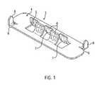
- FIGS. 1 and 2show perspective views of an embodiment of a connector for itself ( FIG. 1 ) and after installation in a printed circuit board, which is identified by reference numeral 1 and on the upper side, a conductor 2 made of copper is provided. On the conductor track 2 is a connection piece 3, whose essential components are described below with reference to the FIGS. 1 and 2 be explained.
- this mounting portion 4In the middle of this mounting portion 4 are located on opposite sides of an elongated recess 5 alternately provided spring tongues 6.
- the spring tongues 6are formed by punching and bending from the connecting piece 3 forming sheet metal strip.
- the spring tongues 6are all to the in FIG. 1 shown lower or contact side of the connecting piece 3 is bent.
- Each spring tongue 6has a convexly convex contact surface 7 with respect to the convex region of the curvature of the spring tongues 6. This contact surface 7 projects beyond the provided in the longitudinal direction of the spring tongue 6 curved outer surface of the spring tongue 6.
- At opposite ends and diagonally to each other 3 holding webs 8are provided. These holding webs are made by punching and bending.
- first of the connecting piece 3 forming sheet metal strips in the longitudinal direction of the metal strip extending stripis cut, which is deformed between the mounting portion 4 and the holding web 8 by bending to a mounting portion 4 on the outside bent over gutter 9, the holding web 8 with the Attachment section connects.
- the terminal 3is formed solely by punching on a metal strip.
- the attachment portion 4forms a contact surface on the circuit board 1 and thus a flat, positionally accurate positioning and contacting to the circuit board.
- the holding webs 8are used for positioning and attachment and the electrical contacting of the connector 3 in the circuit board in a manner to be described.
- the spring tongues 6 in the preferred embodiment of the connection piece and therefore also all the elements thereofare preferably formed from copper beryllium (BeCu25).
- BeCu25copper beryllium
- the contact surfaces 7 of the springare provided with a coating of silver approximately 2.5 .mu.m thick.
- FIG. 2shows the connector 3 after arranging on the circuit board.
- the spring tongues 6are located in a recess 10 (see. FIG. 5 ), which is recessed on the circuit board and which is penetrated for receiving a contact tongue, which is formed by a contact plate, not shown, of this.
- rings 11clarified areas or surfaces for the SMD handling. About these surfaces, the connector 3 is held during assembly and positioned on the circuit board.
- the conductor 2forms the contact surface for the connector 3.
- the attachment portion 4is located over its entire surface against the conductor 2 with its underside.
- the holding web 8extends through a mounting hole 12, which is recessed in the printed circuit board 1 and coated circumferentially with the material of the conductor tracks (copper).
- this mounting hole 12 of the retaining web 8is inserted and fixed by means of solder. This results in a solid electrical contact with the conductor 2 and otherwise an attachment of the connector 3 to the circuit board 1.
- FIG. 4can be seen corresponds to the width of the retaining web 8 approximately the diameter of the mounting hole 12 so that when inserting the retaining web 8 in the mounting hole 12, the connector 3 is fixed very accurately with respect to the circuit board 1.
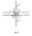
- FIG. 5shows a sectional view taken along line VV as shown in FIG FIG. 2 and thus a cross-sectional view through the elongated recess 5 of the printed circuit board 1.
- the heat-generating PTC elements and their respective contact plates with respect to the representation in FIG. 4are arranged below the circuit board 1.
- As part of this heat generating elementis in FIG. 5 only the end of a contact plate 13, which forms a contact tongue 14, shown.
- This contact tongue 14is passed through the recess 10 of the circuit board 1, ie passes through the printed circuit board 1.
- the passage of the contact tongue 14takes place between the mutually opposite spring tongues 6, which in this case are displaced in the direction of the recess 10 limiting walls 15.
- the spring tongues 6are located in total within the recess 10, ie between the top and bottom of the circuit board 1. It is a very compact design created over the contact tab 14 is electrically connected to a conductor 2 of the circuit board 1 in a simple manner can be.
- the spring tongues 6are formed such that, for example, a contact tongue with the embodiment according to the in FIG. 4 shown contact tongue 14 can also be inserted from the opposite side into the recess 10 and contacted with the circuit board 1. It is preferable to mount all the connectors 3 from the same side on the circuit board 1.
- This side of the printed circuit board 1, referred to below as the component sidecan also be the one which exclusively carries the components mounted on the printed circuit board 1. In such an embodiment, the finished assembly of the circuit board 1 on one side, that is done exclusively by the component side.
Landscapes
- Coupling Device And Connection With Printed Circuit (AREA)
Description
Translated fromGermanDie vorliegende Erfindung betrifft eine elektrische Heizvorrichtung für ein Kraftfahrzeug mit wenigstens einem PTC-Heizelement mit im Wesentlichen parallel zueinander ausgerichteten und zwischen sich mindestens ein PTC-Element aufnehmenden Kontaktblechen und einer Leiterplatte, welche wenigstens eine Ausnehmung ausbildet, die von einer durch ein Kontaktblech ausgebildeten Kontaktzunge zum elektrischen Anschluss des PTC-Elementes an die Leiterplatte durchragt ist.The present invention relates to an electrical heating device for a motor vehicle with at least one PTC heating element with essentially parallel aligned and between at least one PTC element receiving contact plates and a printed circuit board, which forms at least one recess formed by a contact plate formed by a contact tongue for the electrical connection of the PTC element to the printed circuit board is penetrated.
Derartige elektrische Heizvorrichtungen, die auch als PTC-Heizvorrichtungen bezeichnet werden, dienen zur Erwärmung im Kraftfahrzeug. So ist beispielsweise mit der
Ausgewählte Kontaktbleche der einzelnen wärmeerzeugenden Elemente sind seitlich über den Heizblock hinaus verlängert, um Kontaktzungen für den elektrischen Anschluss des Heizblocks zu schaffen. Bei der
Ein ähnlicher Aufbau hinsichtlich der Kontaktierung zwischen der Kontaktzunge und der Leiterplatte ist aus der
Der vorliegenden Erfindung liegt das Problem zugrunde, eine kompakt bauende elektrische Heizvorrichtung anzugeben.The present invention is based on the problem of specifying a compact electrical heater.
Zur Lösung dieses Problems wird mit der vorliegenden Erfindung eine elektrische Heizvorrichtung mit dem Merkmal von Anspruch 1 angegeben. Dieses unterscheidet sich dadurch von dem gattungsbildenden Stand der Technik, dass ein gestanztes Anschlussstück vorgesehen ist, welches elektrisch leitend an eine Leiterbahn der Leiterplatte angeschlossen ist. Das Anschlussstück hat einen auf der Leiterplatte anliegenden Befestigungsabschnitt und zumindest eine in die Ausnehmung hineinragende Federzunge.To solve this problem, the present invention provides an electric heater having the feature of
Eine Leiterplatte im Sinne von Anspruch 1 kann jede Leiterplatte sein, unabhängig davon, ob sie nun mit Bauelementen bestückt ist, oder lediglich Leiterbahnen zur Leitung von Strom zwischen zwei Punkten umfasst. Eine solche Leiterbahn kann beispielsweise vorgesehen sein, um elektrische Anschlüsse an der elektrischen Heizvorrichtung an einer von den Kontaktblechen entfernt liegenden Stelle vorzusehen. Regelmäßig werden die Kontaktbleche geradlinig über den Heizblock und durch die Ausnehmung der Leiterplatte hindurch verlängert. Durch Stanzbearbeitung können zwar Kontaktbleche auch einen in beliebiger Richtung winklig zu der Längserstreckung der Kontaktbleche des Heizblocks ausgerichteten Steckkontakt bereitstellen. Aus fertigungstechnischen Gründen werden solche Ausgestaltungen aber hinsichtlich ihrer räumlichen Ausdehnung als beschränkt angesehen. Dabei ist auch von Interesse, dass der Bauraum zur Unterbringung der elektrischen Heizvorrichtung in dem Kraftfahrzeug regelmäßig beschränkt ist.A printed circuit board in the sense of
Hier setzt die vorliegende Erfindung an und schlägt zum elektrischen Anschluss der die Leiterplatte durchragenden Kontaktzunge vor, zumindest eine in die Ausnehmung hineinragende Federzunge auszubilden. Diese Federzunge ist Teil eines Anschlussstückes, welches neben der besagten Federzunge zumindest einen auf der Leiterplatte in der Regel vollflächig anliegenden Befestigungsabschnitt hat. Dieser Befestigungsabschnitt dient zum Einen der Befestigung des Anschlussstückes an der Leiterplatte. Zum Anderen wird über den Befestigungsabschnitt regelmäßig eine elektrische Verbindung zwischen der Federzunge und damit dem Kontaktblech und wenigstens einer Leiterbahn der Leiterplatte hergestellt.This is where the present invention starts and proposes, for the electrical connection of the contact plate projecting through the printed circuit board, at least one spring tongue projecting into the recess. This spring tongue is part of a connecting piece, which in addition to the said spring tongue has at least one on the printed circuit board generally full-surface fitting portion. This attachment portion serves to one of the attachment of the connector to the circuit board. On the other hand, an electrical connection between the spring tongue and thus the contact plate and at least one conductor track of the printed circuit board is produced via the attachment portion regularly.
Im Gegensatz zum gattungsbildenden Stand der Technik, bei welchem das Federelement zur Halterung und elektrischen Kontaktierung mit der Leiterplatte selbige erheblich überragt, was zu einer erheblichen Erstreckung der Leiterplatte und der darauf befestigten Bauelemente in Längsrichtung der Kontaktbleche führt, befindet sich die das Kontaktblech klemmende Federzunge in der Ausnehmung, die durch die Leiterplatte zum Hindurchführen der Kontaktzunge ausgespart ist.In contrast to the generic state of the art, in which the spring element for holding and electrical contact with the circuit board dominates the same considerably, resulting in a considerable extension of the circuit board and the components mounted thereon in the longitudinal direction of the contact plates, the contact plate is clamping spring tongue in the recess which is recessed by the circuit board for passing the contact tongue.
Bei einer bevorzugten Weiterbildung, die zu keiner substantiellen Vergrößerung der Abmessung der Leiterplatte in Erstreckungsrichtung der Kontaktbleche führt, befindet sich die Federzunge im Wesentlichen in der durch die Leiterplatte gebildeten Ebene. Vorzugsweise ist die Federzunge bei dieser bevorzugten Weiterbildung vollständig innerhalb der Ebene der Leiterplatte vorgesehen, d.h. die Federzunge überragt mit ihrem freien Ende, welches üblicherweise auf der den Befestigungsabschnitt abgewandten Seite der Leiterplatte vorgesehen ist, die Leiterplatte nicht.In a preferred development, which does not lead to a substantial increase in the dimension of the printed circuit board in the direction of extension of the contact sheets, the spring tongue is located substantially in the plane formed by the printed circuit board. Preferably, the spring tongue is provided in this preferred embodiment completely within the plane of the circuit board, i. the spring tongue projects beyond the printed circuit board with its free end, which is usually provided on the side of the printed circuit board facing away from the fastening section.
Vorzugsweise geht die Federzunge unmittelbar von dem Befestigungsabschnitt auf Höhe der Ausnehmung ab und erstreckt sich von dem Befestigungsabschnitt ausschließlich in Richtung auf die Ausnehmung. Die in solcher Weise ausgebildete Federzunge trägt nicht oder nur sehr unwesentlich auf die Dicke der Leiterplatte auf. Der elektrische Anschluss des Kontaktbleches kann daher äußerst raumsparend erfolgen.The spring tongue preferably extends directly from the fastening section at the level of the recess and extends from the fastening section exclusively in the direction of the recess. The trained in such a way spring tongue does not or only very insignificantly on the thickness of the circuit board. The electrical connection of the contact plate can therefore be extremely space-saving.
Im Hinblick auf eine möglichst solide Kontaktierung zwischen der Federzunge und der Kontaktzunge wird gemäß einer weiteren bevorzugten Ausgestaltung der vorliegenden Erfindung vorgeschlagen, die Federzunge mit ihrem freien Ende an einer die Ausnehmung umgebenden Wandung der Leiterplatte abzustützen. Diese Wandung erstreckt sich üblicherweise rechtwinklig zu der Ober- und Unterseite der Leiterplatte. Die solcher Art abgestützte Federzunge kann eine relativ hohe Anpresskraft gegen die Kontaktzunge ausüben, was die Kontaktierung der Kontaktzunge an der Federzunge verbessert.With a view to solid contact as possible between the spring tongue and the contact tongue is proposed according to a further preferred embodiment of the present invention to support the spring tongue with its free end to a surrounding wall of the recess of the circuit board. This wall usually extends at right angles to the top and bottom of the circuit board. The spring tongue supported in this way can exert a relatively high contact force against the contact tongue, which improves the contacting of the contact tongue on the spring tongue.
Im Hinblick auf eine definierte Kontaktfläche zwischen der Federzunge und der Kontaktzunge wird gemäß einer weiteren bevorzugten Ausgestaltung der vorliegenden Erfindung vorgeschlagen, dass die nach Einführen der Kontaktzunge in die Ausnehmung mit der Kontaktzunge zusammenwirkende Oberfläche der Federzunge konvex ausgebildet ist. Diese konvexe Ausgestaltung kann vorzugsweise durch Umformen der Oberfläche der Kontaktzunge erfolgen. Die konvexe Ausgestaltung führt zu einer punkt- bzw. linienförmigen Anlage zwischen der Federzunge und der in der Regel aus einem flachen Blechstreifen gebildeten Kontaktzunge. Dementsprechend wird die von der Federzunge bewirkte Federkraft über eine geringe aber definierte Anlagefläche auf die Kontaktzunge übertragen, was zu einer sicheren und zuverlässigen Kontaktierung führt.With regard to a defined contact surface between the spring tongue and the contact tongue, it is proposed according to a further preferred embodiment of the present invention that the surface of the spring tongue cooperating with the contact tongue after insertion of the contact tongue into the recess is convex. This convex configuration can preferably be done by reshaping the surface of the contact tongue. The convex configuration leads to a point or linear system between the spring tongue and the contact tongue formed usually from a flat sheet metal strip. Accordingly, the spring force caused by the spring tongue is transmitted via a small but defined contact surface on the contact tongue, resulting in a secure and reliable contact.
Gemäß einer weiteren bevorzugten Ausgestaltung der vorliegenden Erfindung sind an gegenüberliegenden Seiten der Ausnehmung jeweils Federzungen ausgebildet. Diese Federzungen ragen sämtlich in die Ausnehmung hinein und sind vorzugsweise mit einem gemeinsamen Befestigungsabschnitt verbunden, der auf der Oberfläche der Leiterbahn anliegt. Die Federzungen sind dabei vorzugsweise versetzt zueinander ausgebildet und durch Herausschneiden und Biegen aus der Blechebene des Halbzeuges in alternierender Weise vorgesehen, so dass die jeweiligen Federzungen gegenüberliegenden Wandungen der Ausnehmung vorgelagert sind und zwischen sich die Kontaktzunge klemmen.According to a further preferred embodiment of the present invention, respective spring tongues are formed on opposite sides of the recess. These spring tongues all protrude into the recess and are preferably connected to a common attachment portion which rests on the surface of the conductor track. The spring tongues are preferably offset from one another and provided by cutting and bending out of the sheet metal plane of the semifinished product in an alternating manner, so that the respective spring tongues are opposite walls of the recess and clamp between them the contact tongue.
Bei einer bevorzugten Weiterbildung liegt der Befestigungsabschnitt auf der dem wenigstens einen PTC-Element zugewandten Seite der Leiterplatte an, so dass beim Einführen der Kontaktzunge unter Aufbringen einer elastischen Vorspannung der Federzunge, die hierbei entstehende Reibkraft über die Anlagefläche zwischen dem Befestigungsabschnitt und der Oberfläche der Leiterplatte gehalten wird. Es ist insbesondere nicht zu befürchten, dass das Anschlussstück, speziell der Befestigungsabschnitt, beim Einbringen der Kontaktzunge in die Ausnehmung von der Leiterplatte abgehoben wird.In a preferred development of the attachment portion is located on the at least one PTC element facing side of the circuit board, so that upon insertion of the contact tongue under application of an elastic bias of the spring tongue, the friction force arising in this case over the contact surface between the mounting portion and the surface of the circuit board is held. In particular, it is not to be feared that the connecting piece, in particular the fastening portion, will be lifted off the printed circuit board when the contact tongue is introduced into the recess.
Gemäß einer weiteren bevorzugten Ausgestaltung der vorliegenden Erfindung weist das Anschlussstück wenigstens einen Haltesteg auf, der durch Stanzen und Umbiegen des das Anschlussstück bildenden Blechstreifens hergestellt ist. Dieser Haltesteg ragt von dem Befestigungsabschnitt ab, regelmäßig in etwa rechtwinklig hierzu und ist in einem an der Leiterplatte ausgesparten Befestigungsloch im Eingriff. Durch diesen Haltesteg wird zum Einen eine lagegenaue Positionierung des Anschlussstückes bei der Montage ermöglicht. Das Anschlussstück ist erst dann an der richtigen Stelle relativ zu der Leiterplatte montiert, wenn der wenigstens eine Haltesteg in dem zugeordneten Befestigungsloch im Eingriff ist.According to a further preferred embodiment of the present invention, the connecting piece has at least one holding web, which is produced by stamping and bending of the sheet metal strip forming the connecting piece. This retaining bar protrudes from the mounting portion, regularly at approximately right angles thereto and is engaged in a recessed on the circuit board mounting hole. By this holding web, a positionally accurate positioning of the connection piece during assembly is made possible on the one hand. The fitting is not mounted in place relative to the printed circuit board until the at least one retaining ridge is engaged in the associated mounting hole.
Gemäß einer bevorzugten Weiterbildung ist das Befestigungsloch des Weiteren mit Lot ausgefüllt und der Haltesteg steht mit einer Leiterbahn der Leiterplatte elektrisch in Verbindung. Dabei kontaktiert das Lot regelmäßig die Umfangsfläche des Befestigungsloches, welches für sich wiederum mit einer elektrisch leitenden Beschichtung ausgekleidet ist. So sollte das Befestigungsloch vorzugsweise innen umfänglich mit einer Kupferbeschichtung versehen sein, über welche eine gute elektrische Verbindung zwischen dem Haltesteg, dem in dem Befestigungsloch aufgenommenen Lot und einer auf der Ober- und/oder Unterseite der Leiterplatte ausgebildeten und mit der Umfangsbeschichtung des Befestigungsloches elektrisch verbundenen Leiterbahn gegeben ist.According to a preferred embodiment, the mounting hole is further filled with solder and the holding web is electrically connected to a conductor track of the printed circuit board. The solder regularly contacts the peripheral surface of the mounting hole, which in turn is lined with an electrically conductive coating. So the mounting hole should preferably be provided on the inside with a copper coating, via which a good electrical connection between the holding web, the solder received in the mounting hole and a conductor formed on the top and / or bottom of the circuit board and electrically connected to the peripheral coating of the mounting hole given is.
Der Haltesteg hat vorzugsweise eine Breite, die in etwa dem Durchmesser des Befestigungsloches entspricht. Dadurch ergib sich eine lagegenaue Positionierung des Anschlussstückes nach Einbringen des Haltesteges in das Befestigungsloch.The holding web preferably has a width which corresponds approximately to the diameter of the mounting hole. This results in a positionally accurate positioning of the connector after insertion of the retaining web in the mounting hole.
Gemäß der Weiterbildung nach Anspruch 10 wird dieses lagegenaue Einbringen des Haltesteges in das Befestigungsloch gefördert. Nach dieser Weiterbildung ist zwischen dem Haltesteg und dem Befestigungsabschnitt, der auf der Leiterplatte aufliegt, ein Zwischensteg vorgesehen, der gegenüber der Leiterplatte gekrümmt ausgebildet ist. Der Haltesteg und der Zwischensteg sind vorzugsweise durch Stanzen des den Befestigungsabschnitt bildenden Bleches zu einem Streifen herausgeschnitten. Der Zwischensteg ist durch Biegen des Streifens gekrümmt gegenüber derjenigen Anlagefläche der Leiterplatte herausgehoben, die für den Befestigungsabschnitt vorgesehen ist. Der von der Unterseite des Befestigungsabschnittes abragende Teil des Streifens erstreckt sich dementsprechend vorzugsweise streng rechtwinklig zu dieser Unterseite, wodurch das lagegenaue Einführen und Positionieren unter Beibehaltung einer flächigen Anlage des Befestigungsabschnittes an der Oberseite der Leiterplatte gewährleistet wird.According to the embodiment according to
Vorzugweise liegt der Befestigungsabschnitt flächig besonders bevorzugt ganzflächig auf einer auf der Oberfläche der Leiterplatte ausgebildeten Leiterbahnen auf.Preferably, the attachment portion is particularly preferably flat over the whole area on a conductor tracks formed on the surface of the printed circuit board.
Weitere Einzelheiten und Vorteile der vorliegenden Erfindung ergeben sich aus der nachfolgenden Beschreibung eines Ausführungsbeispiels in Verbindung mit der Zeichnung. In dieser zeigen:
- Figur 1:
- eine perspektivische Ansicht eines Ausführungsbeispiels des Anschlussstü- ckes;
- Figur 2:
- das in
Figur 1 - Figur 3:
- eine Schnittansicht entlang der Linie III-III gemäß der Darstellung in
Figur 2 - Figur 4:
- eine Schnittansicht entlang der Linie IV-IV gemäß der Darstellung in
Figur 2 - Figur 5:
- eine Schnittansicht entlang der Linie V-V gemäß der Darstellung in
Figur 2
- FIG. 1:
- a perspective view of an embodiment of the Anschlussstü- ckes;
- FIG. 2:
- this in
FIG. 1 shown embodiment in a perspective perspective view after mounting on the circuit board; - FIG. 3:
- a sectional view taken along the line III-III as shown in FIG
FIG. 2 ; - FIG. 4:
- a sectional view taken along the line IV-IV as shown in FIG
FIG. 2 ; and - FIG. 5:
- a sectional view taken along line VV as shown in FIG
FIG. 2 with a contact plate projecting through the printed circuit board.
Die
Das Anschlussstück 3 hat einen durch einen ebenen Blechstreifen ausgebildeten Befestigungsabschnitt 4. In der Mitte dieses Befestigungsabschnittes 4 befinden sich an gegenüberliegenden Seiten einer länglichen Ausnehmung 5 alternierend vorgesehene Federzungen 6. Die Federzungen 6 sind durch Stanzen und Umbiegen aus dem das Anschlussstück 3 bildenden Blechstreifen gebildet. Die Federzungen 6 sind sämtlich zu der in
Wie sich aus der obigen Beschreibung ergibt, ist das Anschlussstück 3 allein durch Stanzbearbeitung an einem Blechstreifen ausgebildet. Dabei bildet der Befestigungsabschnitt 4 eine Anlagefläche auf die Leiterplatte 1 und damit eine ebene, lagegenaue Positionierung und Kontaktierung zu der Leiterplatte. Die Haltestege 8 dienen der Positionierung und Befestigung sowie der elektrischen Kontaktierung des Anschlussstückes 3 in der Leiterplatte in einer noch zu beschreibenden Weise.As is apparent from the above description, the
Die Federzungen 6 bei der bevorzugten Ausgestaltung des Anschlussstückes und daher auch sämtliche Elemente desselben werden vorzugsweise aus Kupferberyllium (BeCu25) gebildet. Aus Kostengründen sind vorzugweise nur die Kontaktflächen 7 der Feder mit einer etwa 2,5 µ-Meter starken Beschichtung aus Silber versehen.The
Die
In
Wie die
Die
Wie
- 11
- Leiterplattecircuit board
- 22
- Leiterbahnconductor path
- 33
- Anschlussstückconnector
- 44
- Befestigungsabschnittattachment section
- 55
- Ausnehmung, AnschlussstückRecess, connection piece
- 66
- Federzungespring tongue
- 77
- Kontaktflächecontact area
- 88th
- Haltestegholding web
- 99
- Zwischensteggutter
- 1010
- Ausnehmung, LeiterplatteRecess, circuit board
- 1111
- Fläche für SMD-BehandlungSurface for SMD treatment
- 1212
- Befestigungslochmounting hole
- 1313
- Kontaktblechcontact sheet
- 1414
- Kontaktzungecontact tongue
- 1515
- Innenwandinner wall
Claims (11)
- An electric heating device for a motor vehicle, comprising at least one PTC heating element with contact metal sheets (13) extending substantially parallel to one another and accommodating between them at least one PTC element, and a printed circuit board (1) having formed therein at least one opening (10) through which a contact tongue (14) projects, which is defined by a contact metal sheet (14) and which serves to establish an electric connection between the PTC heating element and the printed circuit board (1),
characterized by
a punched-out connection piece (3) connected to a conductor path (2) of the printed circuit board (1) in an electrically conductive manner, said connection piece (3) defining a fixing portion (4), which rests on the printed circuit board (1), and at least one spring tongue (6) projecting into the opening (10). - The electric heating device according to claim 1,characterized in that the spring tongue (6) is located substantially within the printed circuit board (1).
- The electric heating device according to claim 1 or 2,characterized in that the free end of the spring tongue (6) rests on a wall (15) surrounding the opening (10).
- The electric heating device according to any of the preceding claims,characterized in that a surface (7) of the spring tongue (6) cooperating with the contact tongue (14) is convex in shape.
- The electric heating device according to claim 4,characterized in that a plurality of spring tongues (6) project into the opening (10) from opposite sides.
- The electric heating device according to claim 4 or 5,characterized in that the spring tongues (6) are arranged on opposite sides of the opening (10) such that they are displaced relative to one another.
- The electric heating device according to any of the preceding claims,characterized in that the fixing portion (4) is arranged on the printed circuit board side facing the at least one PTC element.
- The electric heating device according to any of the preceding claims,characterized in that at least one holding lug (8) projects from the fixing portion (4), said holding lug (8) being produced by punching and bending and engaging a fastening hole (12) formed in the printed circuit board (1).
- The electric heating device according to claim 8,characterized in that the fastening hole (12) is filled with a solder, and that the holding lug (8) is electrically connected to a conductor path (2) of the printed circuit board (1).
- The electric heating device according to claim 8 or 9,characterized in that the holding lug (8) and an intermediate piece (9) located between said holding lug (8) and the fixing portion (4) are cut out, by punching, in the form of a strip from the metal sheet defining the fixing portion (4), and that the intermediate piece (9) is formed into a curved protruding shape by bending the strip relative to a contact surface for the fixing portion (4), said contact surface being defined by the printed circuit board (1).
- The electric heating device according to any of the preceding claims,characterized in that the fixing portion (4) rests on a conductor path (2), which is formed on the surface of the printed circuit board (1), in planar contact therewith.
Priority Applications (4)
| Application Number | Priority Date | Filing Date | Title |
|---|---|---|---|
| ES09004596TES2369840T3 (en) | 2009-03-30 | 2009-03-30 | ELECTRIC HEATING DEVICE FOR A CAR. |
| EP09004596AEP2236330B1 (en) | 2009-03-30 | 2009-03-30 | Electric heater for a motor vehicle |
| US12/728,324US8803036B2 (en) | 2009-03-30 | 2010-03-22 | Electric heating device for a motor vehicle |
| CN2010101403868ACN101854748B (en) | 2009-03-30 | 2010-03-29 | Electric heater for a motor vehicle |
Applications Claiming Priority (1)
| Application Number | Priority Date | Filing Date | Title |
|---|---|---|---|
| EP09004596AEP2236330B1 (en) | 2009-03-30 | 2009-03-30 | Electric heater for a motor vehicle |
Publications (2)
| Publication Number | Publication Date |
|---|---|
| EP2236330A1 EP2236330A1 (en) | 2010-10-06 |
| EP2236330B1true EP2236330B1 (en) | 2011-09-28 |
Family
ID=40680652
Family Applications (1)
| Application Number | Title | Priority Date | Filing Date |
|---|---|---|---|
| EP09004596AActiveEP2236330B1 (en) | 2009-03-30 | 2009-03-30 | Electric heater for a motor vehicle |
Country Status (4)
| Country | Link |
|---|---|
| US (1) | US8803036B2 (en) |
| EP (1) | EP2236330B1 (en) |
| CN (1) | CN101854748B (en) |
| ES (1) | ES2369840T3 (en) |
Cited By (1)
| Publication number | Priority date | Publication date | Assignee | Title |
|---|---|---|---|---|
| EP2897230A1 (en) | 2014-01-21 | 2015-07-22 | Eberspächer catem GmbH & Co. KG | Electrical connection in particular for an electrical heating system of a vehicle |
Families Citing this family (60)
| Publication number | Priority date | Publication date | Assignee | Title |
|---|---|---|---|---|
| US8835017B2 (en)* | 2009-07-29 | 2014-09-16 | Yuan Deng Metals Industrial Co., Ltd. | Metal sheet member having high plastic bonding strength |
| DE102011011692B4 (en)* | 2010-10-18 | 2022-05-05 | Tdk Electronics Ag | Heating module and vaporization device with a heating module |
| EP2505931B2 (en)* | 2011-03-30 | 2022-01-12 | Eberspächer catem GmbH & Co. KG | Electric heating device with a plate element comprising conducting tracks and method for producing such a plate element |
| EP2515387B1 (en) | 2011-04-18 | 2016-06-01 | Eberspächer catem GmbH & Co. KG | Plug |
| TWI451817B (en)* | 2011-05-26 | 2014-09-01 | 豐田自動織機股份有限公司 | Wiring board and method of manufacturing the wiring board |
| EP2608631B1 (en)* | 2011-12-22 | 2016-09-14 | Eberspächer catem GmbH & Co. KG | Element which produces heat |
| DE102011089539B3 (en)* | 2011-12-22 | 2013-04-25 | Behr-Hella Thermocontrol Gmbh | Device for controlling e.g. electrical auxiliary heater for electric vehicle, has printed circuit board fixed with heat coupling surface through connection pins for retaining thermal coupling of component to be cooled with coupling surface |
| US9240644B2 (en) | 2012-08-22 | 2016-01-19 | Amphenol Corporation | High-frequency electrical connector |
| JP5969405B2 (en)* | 2013-01-30 | 2016-08-17 | 日立オートモティブシステムズ株式会社 | Automotive electronic module |
| EP2881678A1 (en)* | 2013-12-03 | 2015-06-10 | Mahle Behr France Rouffach S.A.S | Electric heater |
| EP2881679B1 (en)* | 2013-12-03 | 2017-05-10 | Mahle Behr France Rouffach S.A.S | Electric heater |
| EP2884198B1 (en) | 2013-12-13 | 2016-11-23 | Eberspächer catem GmbH & Co. KG | Electric heating device |
| EP2884199B1 (en) | 2013-12-13 | 2016-11-23 | Eberspächer catem GmbH & Co. KG | Electric heating device |
| EP2884817B1 (en) | 2013-12-13 | 2017-08-30 | Eberspächer catem GmbH & Co. KG | Electric heating device and method for its production |
| EP2884197B1 (en) | 2013-12-13 | 2017-02-08 | Eberspächer catem GmbH & Co. KG | Electric heating device and method for its production |
| JP2015130268A (en)* | 2014-01-07 | 2015-07-16 | トヨタ自動車株式会社 | Terminal connection structure, semiconductor device |
| EP2966934B1 (en)* | 2014-07-08 | 2016-09-14 | Eberspächer catem GmbH & Co. KG | Control device for an electric heating device and method for its production |
| EP3436752B1 (en) | 2016-03-30 | 2021-06-30 | Marine Canada Acquisition Inc. | Vehicle heater and controls therefor |
| FR3056834B1 (en)* | 2016-09-28 | 2019-11-22 | Valeo Japan Co., Ltd. | CONNECTOR FOR POWER ELECTRONIC CIRCUIT |
| CN110088985B (en) | 2016-10-19 | 2022-07-05 | 安费诺有限公司 | Flexible shield for ultra-high speed high density electrical interconnects |
| WO2018116710A1 (en)* | 2016-12-22 | 2018-06-28 | 日立オートモティブシステムズ株式会社 | Electronic control device |
| DE102017210005A1 (en) | 2017-06-14 | 2018-12-20 | Eberspächer Catem Gmbh & Co. Kg | Grommet |
| DE102017210006A1 (en) | 2017-06-14 | 2018-12-20 | Eberspächer Catem Gmbh & Co. Kg | Electromagnetic shielding |
| DE102017219193B3 (en)* | 2017-10-26 | 2019-03-28 | Phoenix Contact Gmbh & Co. Kg | Pluggable ensemble |
| DE102017010211A1 (en) | 2017-11-02 | 2019-05-02 | Eberspächer Catem Gmbh & Co. Kg | Electric heater |
| DE102017221490A1 (en) | 2017-11-30 | 2019-06-06 | Eberspächer Catem Gmbh & Co. Kg | Electric heater |
| EP3544121B1 (en)* | 2018-03-19 | 2022-05-04 | Mahle International GmbH | Electrical heating device |
| US10665973B2 (en) | 2018-03-22 | 2020-05-26 | Amphenol Corporation | High density electrical connector |
| US10931062B2 (en) | 2018-11-21 | 2021-02-23 | Amphenol Corporation | High-frequency electrical connector |
| EP3716729A1 (en)* | 2019-03-26 | 2020-09-30 | Mahle International GmbH | Connector system and heater system |
| DE102019109393B4 (en)* | 2019-04-10 | 2023-02-02 | Lisa Dräxlmaier GmbH | PCB FEEDTHROUGH AND ELECTRICALLY CONDUCTIVE PIN FOR PASSING IN A PCB FEEDTHROUGH |
| TWI887339B (en) | 2020-01-27 | 2025-06-21 | 美商Fci美國有限責任公司 | High speed, high density direct mate orthogonal connector |
| WO2021154702A1 (en) | 2020-01-27 | 2021-08-05 | Fci Usa Llc | High speed connector |
| EP3883336A1 (en)* | 2020-03-20 | 2021-09-22 | Mahle International GmbH | Heating arrangement |
| DE102020114135A1 (en)* | 2020-05-27 | 2021-12-02 | Bayerische Motoren Werke Aktiengesellschaft | Attachment for a motor vehicle, motor vehicle with such an attachment and a method for production |
| USD1002553S1 (en) | 2021-11-03 | 2023-10-24 | Amphenol Corporation | Gasket for connector |
| DE102022123503A1 (en)* | 2022-09-14 | 2024-03-14 | Eberspächer Catem Gmbh & Co. Kg | Electrical heating device with a connection device and method for producing the same |
| DE102022123568A1 (en) | 2022-09-15 | 2024-03-21 | Eberspächer Catem Gmbh & Co. Kg | Control device and method for producing a control device |
| DE102022123572A1 (en) | 2022-09-15 | 2024-03-21 | Eberspächer Catem Gmbh & Co. Kg | Control device and electric heating device comprising such |
| DE102022005120A1 (en) | 2022-09-15 | 2024-03-21 | Eberspächer Catem Gmbh & Co. Kg | Control device |
| DE102023103296A1 (en) | 2023-02-10 | 2024-08-14 | Eberspächer Catem Gmbh & Co. Kg | Electric heating device and method for its manufacture |
| CN115835430B (en)* | 2023-02-13 | 2023-06-13 | 成都顺康三森电子有限责任公司 | Preparation method of flexible PTC heater for intelligent wearing |
| DE102023104034A1 (en) | 2023-02-17 | 2024-08-22 | Eberspächer Catem Gmbh & Co. Kg | Electric heating device and assembly comprising a circuit board and a connector |
| DE102023109279A1 (en) | 2023-04-13 | 2024-10-17 | Eberspächer Catem Gmbh & Co. Kg | Conduit path for an electric heater and corresponding electric heater |
| DE102023112137A1 (en) | 2023-05-09 | 2024-11-14 | Eberspächer Catem Gmbh & Co. Kg | Electric heater |
| DE102023113200A1 (en) | 2023-05-19 | 2024-11-21 | Eberspächer Catem Gmbh & Co. Kg | power connection |
| DE102023121446A1 (en) | 2023-08-10 | 2025-02-13 | Eberspächer Catem Gmbh & Co. Kg | Electric heater |
| DE102023121393A1 (en) | 2023-08-10 | 2025-02-13 | Eberspächer Catem Gmbh & Co. Kg | Electric heater |
| DE102023121384A1 (en) | 2023-08-10 | 2025-02-13 | Eberspächer Catem Gmbh & Co. Kg | Electric heater |
| DE102023121416A1 (en) | 2023-08-10 | 2025-02-13 | Eberspächer Catem Gmbh & Co. Kg | Electric heater |
| DE102023121379A1 (en) | 2023-08-10 | 2025-02-13 | Eberspächer Catem Gmbh & Co. Kg | Electric heating device and electric heating equipment |
| DE102023121380A1 (en) | 2023-08-10 | 2025-02-13 | Eberspächer Catem Gmbh & Co. Kg | Electric heater |
| DE102023121381A1 (en) | 2023-08-10 | 2025-02-13 | Eberspächer Catem Gmbh & Co. Kg | Electric heater |
| DE102023121383A1 (en) | 2023-08-10 | 2025-02-13 | Eberspächer Catem Gmbh & Co. Kg | Electric heater |
| DE102023121445A1 (en) | 2023-08-10 | 2025-02-13 | Eberspächer Catem Gmbh & Co. Kg | Electric heating device and method for heating a medium |
| DE102023121397A1 (en) | 2023-08-10 | 2025-02-13 | Eberspächer Catem Gmbh & Co. Kg | Electric heater |
| DE102023121387A1 (en) | 2023-08-10 | 2025-02-13 | Eberspächer Catem Gmbh & Co. Kg | Electric heater |
| DE102023121436A1 (en) | 2023-08-10 | 2025-02-13 | Eberspächer Catem Gmbh & Co. Kg | Electric heater |
| DE102024105187A1 (en)* | 2024-02-23 | 2025-08-28 | Eberspächer Catem Gmbh & Co. Kg | Electric heater |
| DE102024105184A1 (en)* | 2024-02-23 | 2025-08-28 | Eberspächer Catem Gmbh & Co. Kg | Electric heater |
Family Cites Families (10)
| Publication number | Priority date | Publication date | Assignee | Title |
|---|---|---|---|---|
| US5198640A (en)* | 1991-05-28 | 1993-03-30 | Yang Chiung Hsiang | Fully clad electric ptc heater with a finned protective casing |
| SE522382C2 (en)* | 2000-05-19 | 2004-02-03 | Ericsson Telefon Ab L M | Contact spring unit |
| ATE229892T1 (en) | 2000-05-23 | 2003-01-15 | Catem Gmbh & Co Kg | ELECTRICAL HEATING DEVICE, PARTICULARLY FOR USE IN MOTOR VEHICLES |
| DE10102671C2 (en)* | 2001-01-17 | 2003-12-24 | Eichenauer Heizelemente Gmbh | Electric heating for a motor vehicle |
| DE10226506A1 (en) | 2002-06-14 | 2004-01-08 | Robert Bosch Gmbh | Method, computer program, and control and / or regulating device for operating an internal combustion engine, and internal combustion engine |
| DE502004007603D1 (en)* | 2004-01-28 | 2008-08-28 | Catem Gmbh & Co Kg | Control unit with thermal protection and a control unit comprising the electric heater |
| PT1580495E (en)* | 2004-03-22 | 2011-12-15 | Halla Climate Control Corp | Electric heater |
| CN2703380Y (en)* | 2004-04-30 | 2005-06-01 | 郜长福 | PTC heater used for hairdressing tool |
| DE502006008687D1 (en) | 2006-06-28 | 2011-02-17 | Eberspaecher Catem Gmbh & Co Kg | Electric heater |
| DE102006055872B3 (en)* | 2006-11-23 | 2008-03-13 | Eichenauer Heizelemente Gmbh & Co. Kg | Electrical heater for automobile, has lamellas with elongated holes exhibiting longitudinal edges that clamp heating rods, where portion of elongated holes in each lamella is longer than breadth of heating rods |
- 2009
- 2009-03-30EPEP09004596Apatent/EP2236330B1/enactiveActive
- 2009-03-30ESES09004596Tpatent/ES2369840T3/enactiveActive
- 2010
- 2010-03-22USUS12/728,324patent/US8803036B2/enactiveActive
- 2010-03-29CNCN2010101403868Apatent/CN101854748B/enactiveActive
Cited By (1)
| Publication number | Priority date | Publication date | Assignee | Title |
|---|---|---|---|---|
| EP2897230A1 (en) | 2014-01-21 | 2015-07-22 | Eberspächer catem GmbH & Co. KG | Electrical connection in particular for an electrical heating system of a vehicle |
Also Published As
| Publication number | Publication date |
|---|---|
| US8803036B2 (en) | 2014-08-12 |
| CN101854748A (en) | 2010-10-06 |
| ES2369840T3 (en) | 2011-12-07 |
| US20100243638A1 (en) | 2010-09-30 |
| CN101854748B (en) | 2013-01-02 |
| EP2236330A1 (en) | 2010-10-06 |
Similar Documents
| Publication | Publication Date | Title |
|---|---|---|
| EP2236330B1 (en) | Electric heater for a motor vehicle | |
| EP1777720B1 (en) | Electrical device, particularly relay socket, with spring clip and method of manufacture | |
| EP2037536B1 (en) | Connection terminal | |
| DE4417088C2 (en) | Contact system for chip cards | |
| EP2242327B2 (en) | Electric heating device | |
| EP2076939B1 (en) | Battery sensor unit | |
| EP2897230B1 (en) | Electrical connection in particular for an electrical heating system of a vehicle | |
| DE202015106042U1 (en) | circuit board | |
| WO2015052117A1 (en) | Electronic circuit | |
| DE102009030645A1 (en) | Bridge element, has bridge section electrically connected with bridge tooth, where inner contact section of bridge tooth has distance less than distance between free ends of contact section of bridge tooth | |
| EP1555865B1 (en) | Assembly of a trap circuit with discrete, passive electronic components | |
| EP2741371B1 (en) | Plug connector and apparatus with such a plug-type connector | |
| DE102010008354A1 (en) | Electrical terminal i.e. spring clip, for electrical connection of guard in printed circuit board, has receiving opening provided at connecting device into which contact pin is inserted to contact and solder circuit board | |
| DE102006000958B4 (en) | Electric device | |
| DE102016107898B4 (en) | Lateral PCB connection | |
| DE2609291C2 (en) | Screwless connection terminal for power transmission from electrical conductors | |
| DE102017110060B4 (en) | Method for producing an arrangement and arrangement with a busbar for a connection terminal for contacting a plurality of electrical conductors and an electrical connection terminal | |
| DE102017108444B4 (en) | Electrical contact element for a printed circuit board and power interface equipped therewith | |
| DE102005033593B3 (en) | Contact spring in a support frame of an antenna amplifier of a vehicle | |
| DE102004053577B4 (en) | current bridge | |
| DE10306618B4 (en) | Planar contact structure with contact tongues for a variable plug-in position | |
| DE102019134369B4 (en) | Leadframe for wire components with backdrop structure | |
| EP2534736B1 (en) | Stackable clamping carrier elements for flat assemblies | |
| EP4115475B1 (en) | Connecting apparatus and also assembly and electronic device | |
| EP3537122B1 (en) | Electrical temperature sensor |
Legal Events
| Date | Code | Title | Description |
|---|---|---|---|
| PUAI | Public reference made under article 153(3) epc to a published international application that has entered the european phase | Free format text:ORIGINAL CODE: 0009012 | |
| 17P | Request for examination filed | Effective date:20100223 | |
| AK | Designated contracting states | Kind code of ref document:A1 Designated state(s):AT BE BG CH CY CZ DE DK EE ES FI FR GB GR HR HU IE IS IT LI LT LU LV MC MK MT NL NO PL PT RO SE SI SK TR | |
| AX | Request for extension of the european patent | Extension state:AL BA RS | |
| GRAP | Despatch of communication of intention to grant a patent | Free format text:ORIGINAL CODE: EPIDOSNIGR1 | |
| GRAS | Grant fee paid | Free format text:ORIGINAL CODE: EPIDOSNIGR3 | |
| AKX | Designation fees paid | Designated state(s):DE ES FR GB IT | |
| GRAA | (expected) grant | Free format text:ORIGINAL CODE: 0009210 | |
| AK | Designated contracting states | Kind code of ref document:B1 Designated state(s):DE ES FR GB IT | |
| REG | Reference to a national code | Ref country code:GB Ref legal event code:FG4D Free format text:NOT ENGLISH | |
| REG | Reference to a national code | Ref country code:ES Ref legal event code:FG2A Ref document number:2369840 Country of ref document:ES Kind code of ref document:T3 Effective date:20111207 | |
| REG | Reference to a national code | Ref country code:DE Ref legal event code:R096 Ref document number:502009001420 Country of ref document:DE Effective date:20111222 | |
| PLBE | No opposition filed within time limit | Free format text:ORIGINAL CODE: 0009261 | |
| STAA | Information on the status of an ep patent application or granted ep patent | Free format text:STATUS: NO OPPOSITION FILED WITHIN TIME LIMIT | |
| 26N | No opposition filed | Effective date:20120629 | |
| REG | Reference to a national code | Ref country code:DE Ref legal event code:R097 Ref document number:502009001420 Country of ref document:DE Effective date:20120629 | |
| PGFP | Annual fee paid to national office [announced via postgrant information from national office to epo] | Ref country code:ES Payment date:20120321 Year of fee payment:4 | |
| GBPC | Gb: european patent ceased through non-payment of renewal fee | Effective date:20130330 | |
| PG25 | Lapsed in a contracting state [announced via postgrant information from national office to epo] | Ref country code:GB Free format text:LAPSE BECAUSE OF NON-PAYMENT OF DUE FEES Effective date:20130330 | |
| REG | Reference to a national code | Ref country code:ES Ref legal event code:FD2A Effective date:20140606 | |
| PG25 | Lapsed in a contracting state [announced via postgrant information from national office to epo] | Ref country code:ES Free format text:LAPSE BECAUSE OF NON-PAYMENT OF DUE FEES Effective date:20130331 | |
| REG | Reference to a national code | Ref country code:FR Ref legal event code:PLFP Year of fee payment:8 | |
| REG | Reference to a national code | Ref country code:FR Ref legal event code:PLFP Year of fee payment:9 | |
| REG | Reference to a national code | Ref country code:FR Ref legal event code:PLFP Year of fee payment:10 | |
| REG | Reference to a national code | Ref country code:FR Ref legal event code:PLFP Year of fee payment:15 | |
| PGFP | Annual fee paid to national office [announced via postgrant information from national office to epo] | Ref country code:IT Payment date:20240329 Year of fee payment:16 Ref country code:FR Payment date:20240320 Year of fee payment:16 | |
| PGFP | Annual fee paid to national office [announced via postgrant information from national office to epo] | Ref country code:DE Payment date:20250319 Year of fee payment:17 |