EP2236100B1 - Microfracture instrument - Google Patents
Microfracture instrumentDownload PDFInfo
- Publication number
- EP2236100B1 EP2236100B1EP10157697.3AEP10157697AEP2236100B1EP 2236100 B1EP2236100 B1EP 2236100B1EP 10157697 AEP10157697 AEP 10157697AEP 2236100 B1EP2236100 B1EP 2236100B1
- Authority
- EP
- European Patent Office
- Prior art keywords
- sheath
- drill
- bone
- shaft
- tip
- Prior art date
- Legal status (The legal status is an assumption and is not a legal conclusion. Google has not performed a legal analysis and makes no representation as to the accuracy of the status listed.)
- Active
Links
- 208000013201Stress fractureDiseases0.000titledescription35
- 210000000988bone and boneAnatomy0.000claimsdescription31
- 201000009859OsteochondrosisDiseases0.000claimsdescription2
- 238000000034methodMethods0.000description17
- 230000007547defectEffects0.000description7
- 210000000845cartilageAnatomy0.000description6
- 238000003780insertionMethods0.000description5
- 230000037431insertionEffects0.000description5
- 210000003127kneeAnatomy0.000description4
- 206010061762ChondropathyDiseases0.000description3
- 238000005553drillingMethods0.000description3
- 210000003484anatomyAnatomy0.000description2
- 210000004369bloodAnatomy0.000description2
- 239000008280bloodSubstances0.000description2
- 210000002798bone marrow cellAnatomy0.000description2
- 238000012986modificationMethods0.000description2
- 230000004048modificationEffects0.000description2
- 210000001519tissueAnatomy0.000description2
- 230000009772tissue formationEffects0.000description2
- 208000002055Bankart LesionsDiseases0.000description1
- 206010007710Cartilage injuryDiseases0.000description1
- 210000001188articular cartilageAnatomy0.000description1
- 230000001419dependent effectEffects0.000description1
- 238000000691measurement methodMethods0.000description1
- HLXZNVUGXRDIFK-UHFFFAOYSA-Nnickel titaniumChemical compound[Ti].[Ti].[Ti].[Ti].[Ti].[Ti].[Ti].[Ti].[Ti].[Ti].[Ti].[Ni].[Ni].[Ni].[Ni].[Ni].[Ni].[Ni].[Ni].[Ni].[Ni].[Ni].[Ni].[Ni].[Ni]HLXZNVUGXRDIFK-UHFFFAOYSA-N0.000description1
- 229910001000nickel titaniumInorganic materials0.000description1
Images


Classifications
- A—HUMAN NECESSITIES
- A61—MEDICAL OR VETERINARY SCIENCE; HYGIENE
- A61B—DIAGNOSIS; SURGERY; IDENTIFICATION
- A61B17/00—Surgical instruments, devices or methods
- A61B17/16—Instruments for performing osteoclasis; Drills or chisels for bones; Trepans
- A61B17/1613—Component parts
- A61B17/1633—Sleeves, i.e. non-rotating parts surrounding the bit shaft, e.g. the sleeve forming a single unit with the bit shaft
- A—HUMAN NECESSITIES
- A61—MEDICAL OR VETERINARY SCIENCE; HYGIENE
- A61B—DIAGNOSIS; SURGERY; IDENTIFICATION
- A61B17/00—Surgical instruments, devices or methods
- A61B17/16—Instruments for performing osteoclasis; Drills or chisels for bones; Trepans
- A61B17/1604—Chisels; Rongeurs; Punches; Stamps
- A—HUMAN NECESSITIES
- A61—MEDICAL OR VETERINARY SCIENCE; HYGIENE
- A61B—DIAGNOSIS; SURGERY; IDENTIFICATION
- A61B17/00—Surgical instruments, devices or methods
- A61B17/16—Instruments for performing osteoclasis; Drills or chisels for bones; Trepans
- A61B17/1662—Instruments for performing osteoclasis; Drills or chisels for bones; Trepans for particular parts of the body
- A61B17/1675—Instruments for performing osteoclasis; Drills or chisels for bones; Trepans for particular parts of the body for the knee
- A—HUMAN NECESSITIES
- A61—MEDICAL OR VETERINARY SCIENCE; HYGIENE
- A61B—DIAGNOSIS; SURGERY; IDENTIFICATION
- A61B17/00—Surgical instruments, devices or methods
- A61B17/16—Instruments for performing osteoclasis; Drills or chisels for bones; Trepans
- A61B17/1613—Component parts
- A61B17/1631—Special drive shafts, e.g. flexible shafts
- A—HUMAN NECESSITIES
- A61—MEDICAL OR VETERINARY SCIENCE; HYGIENE
- A61B—DIAGNOSIS; SURGERY; IDENTIFICATION
- A61B17/00—Surgical instruments, devices or methods
- A61B17/16—Instruments for performing osteoclasis; Drills or chisels for bones; Trepans
- A61B17/1642—Instruments for performing osteoclasis; Drills or chisels for bones; Trepans for producing a curved bore
- A—HUMAN NECESSITIES
- A61—MEDICAL OR VETERINARY SCIENCE; HYGIENE
- A61B—DIAGNOSIS; SURGERY; IDENTIFICATION
- A61B17/00—Surgical instruments, devices or methods
- A61B17/32—Surgical cutting instruments
- A61B17/320016—Endoscopic cutting instruments, e.g. arthroscopes, resectoscopes
- A61B17/32002—Endoscopic cutting instruments, e.g. arthroscopes, resectoscopes with continuously rotating, oscillating or reciprocating cutting instruments
- A61B2017/320032—Details of the rotating or oscillating shaft, e.g. using a flexible shaft
Definitions
- the present inventionis directed to surgical instruments and, more particularly, to a device for treating chondral defects of the knee.
- articular cartilage defectsTreatment of articular cartilage defects is typically accomplished by the microfracture procedure. This procedure is performed arthroscopically. Although articular cartilage defects may occur in any joint, the microfracture procedure is typically performed in the knee or shoulder. The surgeon visually assesses the defect and performs the procedure using special instruments that are inserted through small incisions around the joint. Unstable and loose cartilage is removed from the exposed bone so that there is a stable edge of cartilage surrounding the defect. Multiple holes (also called microfractures) are then made in the exposed bone about 3 to 4mm apart. Bone marrow cells and blood from the holes combine to form a "super clot" that completely covers the damaged area. This marrow-rich clot is the basis for the new tissue formation. The microfracture technique produces a rough bone surface to which the clot adheres more easily. This clot eventually matures into firm repair tissue that becomes smooth and durable.
- the instruments currently used to make the microfracturesare manual instruments such as curved picks and/or nitinol wires and guides.
- One powered optionis a subchondral drill which is a straight drill covered by an outer sheath. The outer sheath covers the drill tip until it contacts bone and then the drill tip advances axially into the bone.
- the manual instrumentsare undesirable in that they typically require two hands to use since a mallet is used to drive the instruments into the bone.
- the impact loading of the malletmay cause the pick to slide or gouge the target site rather than puncture the site perpendicular to the axis of the trocar tip.
- the straight drill power instrumentdoes not provide adequate accessibility or visibility to the site which is typically in a joint space.
- the present inventionprovides an instrument for forming microfractures quickly and at pre-determined angles.
- the instrumenttakes less time and replaces the use of multiple manual instruments.
- the instrumentattaches to a power system such as that used for shavers and burrs to quickly drill small diameter holes at pre-determined angles into bone.
- the instrumentis provided with a flexible trocar tip and a curved outer sheath.
- the shaft of the flexible trocar tipconnects to the hand piece.
- the outer sheathprotects the sharp trocar tip during insertion and is retracted once positioned to expose the sharp trocar tip.
- the instrumentallows the surgeon to quickly place the microfractures in the desired position using only one instrument attached to power.
- the present inventionprovides a microfracture instrument for forming small diameter holes in bone.
- the microfracture instrument of the present inventionis designed to attach to a power system (such as one used for shavers and burrs, for example) to quickly drill small diameter holes at pre-determined angles into bone.
- the microfracture instrumentis provided with a flexible trocar tip and a curved outer sheath.
- the shaft of the flexible trocar tipconnects to the hand piece.
- the outer sheathprotects the sharp trocar tip during insertion and is retracted once positioned to expose the sharp trocar tip.
- the instrumentallows the surgeon to quickly place the microfractures at the desired position using only one instrument attached to power.
- An examplary method of drilling a hole in a bone by inter aliais as follows; providing a shaft with a flexible end, the flexible end being coupled to a drill tip; providing a cannulated sheath with a distal end and a proximal end, the distal end of the sheath being curved and housing the drill tip; and retracting the sheath to cause the drill tip to extend beyond the distal end of the sheath.
- FIGS. 1-12illustrate an exemplary microfracture instrument 100 of the present invention for forming small diameter holes in bone.
- the microfracture instrument 100 of the present inventionmay be employed during a microfracture procedure, which is conducted arthroscopically to treat articular cartilage defects, for example, chondral defects of the knee.
- the surgeonvisually assesses the defect and performs the procedure using special instruments that are inserted through small incisions on the knee. After assessing the cartilage damage, any unstable or loose cartilage is removed from the exposed bone, leaving a stable edge of cartilage around the defect.
- microfracturesMultiple holes (or microfractures) are then made in the exposed bone about 3 to 4mm apart. Bone marrow cells and blood from the holes combine to form a "super clot" that completely covers the damaged area. This marrow-rich clot is the basis for the new tissue formation.
- the microfracture techniqueproduces a rough bone surface that the clot adheres to more easily. This clot eventually matures into firm repair tissue that becomes smooth and durable. Similar microfracture procedures are used in other surgical sites to treat similar bone and cartilage defects, such as Hill-Sachs lesions in the shoulder.
- microfracture instrument 100 of the present inventionincludes an outer assembly 20 and an inner assembly 50.
- the microfracture instrument 100connects to a shaver hand piece (not shown) for power.
- the outer assembly 20includes an outer sheath 29 having a cannulated shaft provided with a distal 25 and proximal end 27.
- the distal end 25 of the sheath 29is curved ( FIG. 1 ).
- the angle of curvaturemay be between about 5 to about 80 degrees, preferably between about 30 to about 60 degrees.
- the outer assembly 20also includes an outer hub 21 with a retaining ring 25. The outer hub 21 is designed to receive the inner assembly 50 through a most proximal opening 28 ( FIG. 9 ).
- the outer hub 21is also provided with an actuator mechanism 35 ( FIG. 9 ) for moving the sheath 29 along a longitudinal axis of the microfracture instrument 100.
- the proximal end 27 of the sheath 29connects to the actuator mechanism 35.
- the actuator mechanism 35is a lever, but one skilled in the art will recognize alternate embodiments such as a button or a ratchet for moving the shaft along the longitudinal axis.
- the outer assembly 20is further illustrated in more detail in FIG. 12 .
- the outer assembly 20includes the outer sheath 29, the actuator 35, the spring 56, the outer hub 21, and a cap 90.
- the cap 90is shown in greater detail in FIG. 11 .
- inner assembly 50 of the microfracture instrument 100is illustrated in more detail in FIGS. 3-6 and 8 .
- inner assembly 50comprises an inner shaft 70 extending from a proximal end 77 to a distal end 75.
- the distal end 75 of the inner shafthouses a drill tip or trocar tip 60 for creating small diameter holes in bone. Details of trocar tip 60 are illustrated in FIG. 8 , although the drill tip could have other geometries and could be fluted or in the form of a bur, for example.
- the inner assembly 50further includes an inner hub 53, a thrust washer 54, a spring 56, and a corresponding spring retainer 57.
- the proximal end 77 of the inner shaft 70connects to the inner hub 53 ( FIG. 3 ).
- inner hub 53connects to a shaver hand piece for power to drive the trocar tip 60 into bone.
- the inner shaft 70has a flexible portion 55 (a flex coil 55 shown in FIG. 5 ) allowing the inner assembly 50 to conform to the curvature of the distal end 25 of the outer sheath 29 of the outer assembly 20.
- the outer sheath 29 of the microfracture instrument 100When inserted into the joint space, the outer sheath 29 of the microfracture instrument 100 covers the trocar tip 60 protecting the surrounding anatomy. Once the desired location for creating the microfracture is located through the scope, the surgeon can manipulate the lever/actuator 35 to retract the sheath 29 thereby exposing the trocar tip 60. Once the tip 60 is exposed, the surgeon may turn on the power to create the hole in the bone. This technique provides the surgeon with more accessibility to the bone in the joint space due to the curvature of the outer sheath. The profile of the instrument 100 is also reduced since the tip is retracted during insertion resulting in better placement of the instrument in the joint space. An additional safety feature is the protection of the surrounding anatomy from an exposed tip during insertion of the instrument prior to drilling.
- the damaged articular cartilage areais prepared in the standard fashion.
- the instrument 100is then attached to a handpiece 110 with the trocar tip 60 retracted safely within the outer sheath 29.
- the instrument 100is passed into the joint space 140 through a cannula or percutaneously 130.
- the actuator mechanism 35is then actuated to laterally move outer sheath 29, thereby exposing the trocar tip 60 so that the trocar tip 60 extends out of the outer sheath 29.
- the trocar tip 60is placed in the appropriate location for forming a hole 122.
- the handpiece 110is energized to rotate the trocar tip 60 and the trocar tip 60 is pushed into bone 120 until the outer sheath 29 contacts bone 120, thereby forming a 1.5 mm hole 122 approximately 3 mm deep in the bone 120.
- the instrument 100is retracted while the handpiece 110 is still energized and the trocar tip 60 is rotating.
- the trocar tip 60is retracted by raising the actuator 35 so that the trocar tip 60 is housed in outer sheath 29 and the instrument 100 is removed from the joint space.
- the instrument 100is also an ideal tool for marking the femoral tunnel location in ACL reconstructive procedures by following the above steps and using the trocar tip 60 to mark a tunnel location within the femoral notch.
- the approximate tunnel locationcan be determined through the medial portal by placing the end of the sheath 29 at the over-top-position.
- the trailing edge of the laser mark 12which is the edge of the mark 12 farthest from the end of the sheath 29 from which the trocar tip 60 extends, is used to reference the center of the tunnel in a single bundle ACL technique.
- the leading edge of the laser mark 12which is the edge of the mark 12 nearest to the end of the sheath 29 from which the trocar tip 60 extends, is used to reference the center of the posterior tunnel in a double bundle ACL technique. After marking its position, the same measurement method is used to reference the center of the anterior tunnel referenced from the previously marked posterior tunnel position. Further, the leading and trailing edges of the laser mark 12 may be used to measure osteochondral defects.
- the laser mark 12is 2 mm wide, the leading edge is 5 mm from the end of the sheath 29 from which the trocar tip 60 extends and the trailing edge is 7 mm from the end of the sheath 29 from which the trocar tip 60 extends. In other embodiments, different widths and distances may be used.
Landscapes
- Health & Medical Sciences (AREA)
- Surgery (AREA)
- Life Sciences & Earth Sciences (AREA)
- Biomedical Technology (AREA)
- Medical Informatics (AREA)
- Orthopedic Medicine & Surgery (AREA)
- Oral & Maxillofacial Surgery (AREA)
- Engineering & Computer Science (AREA)
- Dentistry (AREA)
- Heart & Thoracic Surgery (AREA)
- Nuclear Medicine, Radiotherapy & Molecular Imaging (AREA)
- Molecular Biology (AREA)
- Animal Behavior & Ethology (AREA)
- General Health & Medical Sciences (AREA)
- Public Health (AREA)
- Veterinary Medicine (AREA)
- Surgical Instruments (AREA)
Description
- The present invention is directed to surgical instruments and, more particularly, to a device for treating chondral defects of the knee.
- Treatment of articular cartilage defects is typically accomplished by the microfracture procedure. This procedure is performed arthroscopically. Although articular cartilage defects may occur in any joint, the microfracture procedure is typically performed in the knee or shoulder. The surgeon visually assesses the defect and performs the procedure using special instruments that are inserted through small incisions around the joint. Unstable and loose cartilage is removed from the exposed bone so that there is a stable edge of cartilage surrounding the defect. Multiple holes (also called microfractures) are then made in the exposed bone about 3 to 4mm apart. Bone marrow cells and blood from the holes combine to form a "super clot" that completely covers the damaged area. This marrow-rich clot is the basis for the new tissue formation. The microfracture technique produces a rough bone surface to which the clot adheres more easily. This clot eventually matures into firm repair tissue that becomes smooth and durable.
- The instruments currently used to make the microfractures are manual instruments such as curved picks and/or nitinol wires and guides. One powered option is a subchondral drill which is a straight drill covered by an outer sheath. The outer sheath covers the drill tip until it contacts bone and then the drill tip advances axially into the bone. The manual instruments are undesirable in that they typically require two hands to use since a mallet is used to drive the instruments into the bone. In addition, the impact loading of the mallet may cause the pick to slide or gouge the target site rather than puncture the site perpendicular to the axis of the trocar tip. The straight drill power instrument does not provide adequate accessibility or visibility to the site which is typically in a joint space.
- An instrument that can form the microfractures quickly and at pre-determined angles with repeatability is needed. Also needed is an instrument that allows the surgeon to quickly place the microfractures in the desired position using only one instrument attached to power, and with improved accessibility and visibility to the site. Document
US 2005/0203527 A1 , which forms the basis of the preamble of claim 1, discloses a drill on the end of a flexible shaft which can be retracted inside a distally curved cannulated shaft. - Claim 1 defines the scope of the invention and the dependent claims disclose the preferred embodiments. The present invention provides an instrument for forming microfractures quickly and at pre-determined angles. The instrument takes less time and replaces the use of multiple manual instruments. The instrument attaches to a power system such as that used for shavers and burrs to quickly drill small diameter holes at pre-determined angles into bone. The instrument is provided with a flexible trocar tip and a curved outer sheath. The shaft of the flexible trocar tip connects to the hand piece. The outer sheath protects the sharp trocar tip during insertion and is retracted once positioned to expose the sharp trocar tip. The instrument allows the surgeon to quickly place the microfractures in the desired position using only one instrument attached to power.
- These and other features and advantages of the invention will be more apparent from the following detailed description that is provided in connection with the accompanying drawings and illustrated exemplary embodiments of the invention.
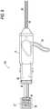
FIG. 1 illustrates a side view of a microfracture instrument of the present invention with the trocar tip exposed;FIG. 1(a) illustrates an enlarged view of the trocar tip of the microfracture instrument ofFIG. 1 ;FIG. 2 illustrates a side view of the outer assembly of the microfracture instrument ofFIG. 1 ;FIG. 3 illustrates a side view of the inner assembly of the microfracture instrument ofFIG. 1 attached to the inner hub;FIG. 4 illustrates a side view of the inner assembly ofFIG. 3 (without the inner hub);FIG. 5 illustrates a side view of the flex coil of the inner assembly ofFIG. 3 ;FIG. 5(a) illustrates an end view of the flex coil of the inner assembly ofFIG. 5 ;FIG. 6 illustrates a side view of the drive tube of the inner assembly ofFIG. 3 ;FIG. 6(a) illustrates an end view of the drive tube of the inner assembly ofFIG. 6 ;FIG. 7 illustrates a side view of the outer sheath of the outer assembly ofFIG. 2 ;FIG. 7(a) illustrates an end view of the outer sheath of the outer assembly ofFIG. 7 ;FIG. 8 illustrates a side view of the trocar tip of the inner assembly ofFIG. 3 ;FIG. 8(a) illustrates a side view of the trocar tip ofFIG. 8 , but rotated for about 90 degrees;FIG. 9 illustrates a transparent side view of the microfracture instrument ofFIG. 1 ;FIGS. 10 and 10(a) illustrate different views of the outer hub of the microfracture instrument ofFIG. 1 ;FIG. 11 illustrates a side view of the molded cap of the microfracture instrument ofFIG. 1 ;FIG. 12 illustrates a side view of various parts of the microfracture instrument ofFIG. 1 ; andFIG. 13 illustrates an examplary method of using the microfracture instrument ofFIG. 1 .- The following description is provided to enable any person skilled in the art to make and use the invention and sets forth the best modes contemplated by the inventors of carrying out their invention. Various modifications, however, will remain readily apparent to those skilled in the art.
- The present invention provides a microfracture instrument for forming small diameter holes in bone. The microfracture instrument of the present invention is designed to attach to a power system (such as one used for shavers and burrs, for example) to quickly drill small diameter holes at pre-determined angles into bone. The microfracture instrument is provided with a flexible trocar tip and a curved outer sheath. The shaft of the flexible trocar tip connects to the hand piece. The outer sheath protects the sharp trocar tip during insertion and is retracted once positioned to expose the sharp trocar tip. The instrument allows the surgeon to quickly place the microfractures at the desired position using only one instrument attached to power.
- An examplary method of drilling a hole in a bone byinter alia is as follows; providing a shaft with a flexible end, the flexible end being coupled to a drill tip; providing a cannulated sheath with a distal end and a proximal end, the distal end of the sheath being curved and housing the drill tip; and retracting the sheath to cause the drill tip to extend beyond the distal end of the sheath.
- Referring now to the drawings, where like elements are designated by like reference numerals,
FIGS. 1-12 illustrate anexemplary microfracture instrument 100 of the present invention for forming small diameter holes in bone. - The
microfracture instrument 100 of the present invention may be employed during a microfracture procedure, which is conducted arthroscopically to treat articular cartilage defects, for example, chondral defects of the knee. The surgeon visually assesses the defect and performs the procedure using special instruments that are inserted through small incisions on the knee. After assessing the cartilage damage, any unstable or loose cartilage is removed from the exposed bone, leaving a stable edge of cartilage around the defect. - Multiple holes (or microfractures) are then made in the exposed bone about 3 to 4mm apart. Bone marrow cells and blood from the holes combine to form a "super clot" that completely covers the damaged area. This marrow-rich clot is the basis for the new tissue formation. The microfracture technique produces a rough bone surface that the clot adheres to more easily. This clot eventually matures into firm repair tissue that becomes smooth and durable. Similar microfracture procedures are used in other surgical sites to treat similar bone and cartilage defects, such as Hill-Sachs lesions in the shoulder.
- As illustrated in
FIGS. 1-12 ,microfracture instrument 100 of the present invention includes anouter assembly 20 and aninner assembly 50. Themicrofracture instrument 100 connects to a shaver hand piece (not shown) for power. - As illustrated in more detail in
FIGS. 2 and7 , theouter assembly 20 includes anouter sheath 29 having a cannulated shaft provided with a distal 25 andproximal end 27. In an exemplary embodiment, thedistal end 25 of thesheath 29 is curved (FIG. 1 ). The angle of curvature may be between about 5 to about 80 degrees, preferably between about 30 to about 60 degrees. As also illustrated inFIG. 2 , theouter assembly 20 also includes anouter hub 21 with a retainingring 25. Theouter hub 21 is designed to receive theinner assembly 50 through a most proximal opening 28 (FIG. 9 ). - The
outer hub 21 is also provided with an actuator mechanism 35 (FIG. 9 ) for moving thesheath 29 along a longitudinal axis of themicrofracture instrument 100. Theproximal end 27 of thesheath 29 connects to theactuator mechanism 35. In an exemplary embodiment only, theactuator mechanism 35 is a lever, but one skilled in the art will recognize alternate embodiments such as a button or a ratchet for moving the shaft along the longitudinal axis. - The
outer assembly 20 is further illustrated in more detail inFIG. 12 . Theouter assembly 20 includes theouter sheath 29, theactuator 35, thespring 56, theouter hub 21, and acap 90. Thecap 90 is shown in greater detail inFIG. 11 . - The
inner assembly 50 of themicrofracture instrument 100 is illustrated in more detail inFIGS. 3-6 and8 . As illustrated inFIG. 3 ,inner assembly 50 comprises aninner shaft 70 extending from aproximal end 77 to adistal end 75. Thedistal end 75 of the inner shaft houses a drill tip ortrocar tip 60 for creating small diameter holes in bone. Details oftrocar tip 60 are illustrated inFIG. 8 , although the drill tip could have other geometries and could be fluted or in the form of a bur, for example. As shown inFIG. 3 , theinner assembly 50 further includes aninner hub 53, athrust washer 54, aspring 56, and acorresponding spring retainer 57. - The
proximal end 77 of theinner shaft 70 connects to the inner hub 53 (FIG. 3 ). In turn,inner hub 53 connects to a shaver hand piece for power to drive thetrocar tip 60 into bone. Theinner shaft 70 has a flexible portion 55 (aflex coil 55 shown inFIG. 5 ) allowing theinner assembly 50 to conform to the curvature of thedistal end 25 of theouter sheath 29 of theouter assembly 20. - When inserted into the joint space, the
outer sheath 29 of themicrofracture instrument 100 covers thetrocar tip 60 protecting the surrounding anatomy. Once the desired location for creating the microfracture is located through the scope, the surgeon can manipulate the lever/actuator 35 to retract thesheath 29 thereby exposing thetrocar tip 60. Once thetip 60 is exposed, the surgeon may turn on the power to create the hole in the bone. This technique provides the surgeon with more accessibility to the bone in the joint space due to the curvature of the outer sheath. The profile of theinstrument 100 is also reduced since the tip is retracted during insertion resulting in better placement of the instrument in the joint space. An additional safety feature is the protection of the surrounding anatomy from an exposed tip during insertion of the instrument prior to drilling. - An exemplary method of preparation and insertion of the instrument 100 (shown in use in
FIG. 13 ) is detailed bellow with reference to specific steps: - The damaged articular cartilage area is prepared in the standard fashion.
- The
instrument 100 is then attached to ahandpiece 110 with thetrocar tip 60 retracted safely within theouter sheath 29. - Next, the
instrument 100 is passed into thejoint space 140 through a cannula or percutaneously 130. - The
actuator mechanism 35 is then actuated to laterally moveouter sheath 29, thereby exposing thetrocar tip 60 so that thetrocar tip 60 extends out of theouter sheath 29. - Next, the
trocar tip 60 is placed in the appropriate location for forming ahole 122. - The
handpiece 110 is energized to rotate thetrocar tip 60 and thetrocar tip 60 is pushed intobone 120 until theouter sheath 29contacts bone 120, thereby forming a 1.5mm hole 122 approximately 3 mm deep in thebone 120. - The
instrument 100 is retracted while thehandpiece 110 is still energized and thetrocar tip 60 is rotating. - The above steps are repeated as needed on different locations of the damaged cartilage as needed until the micro-drilling procedure is complete.
- Thereafter, the
trocar tip 60 is retracted by raising theactuator 35 so that thetrocar tip 60 is housed inouter sheath 29 and theinstrument 100 is removed from the joint space. - The
instrument 100 is also an ideal tool for marking the femoral tunnel location in ACL reconstructive procedures by following the above steps and using thetrocar tip 60 to mark a tunnel location within the femoral notch. Using the laser mark 12 (shown inFIG. 2 ) on thesheath 29, the approximate tunnel location can be determined through the medial portal by placing the end of thesheath 29 at the over-top-position. - The trailing edge of the
laser mark 12, which is the edge of themark 12 farthest from the end of thesheath 29 from which thetrocar tip 60 extends, is used to reference the center of the tunnel in a single bundle ACL technique. - The leading edge of the
laser mark 12, which is the edge of themark 12 nearest to the end of thesheath 29 from which thetrocar tip 60 extends, is used to reference the center of the posterior tunnel in a double bundle ACL technique. After marking its position, the same measurement method is used to reference the center of the anterior tunnel referenced from the previously marked posterior tunnel position. Further, the leading and trailing edges of thelaser mark 12 may be used to measure osteochondral defects. - In one embodiment, the
laser mark 12 is 2 mm wide, the leading edge is 5 mm from the end of thesheath 29 from which thetrocar tip 60 extends and the trailing edge is 7 mm from the end of thesheath 29 from which thetrocar tip 60 extends. In other embodiments, different widths and distances may be used. - Although the present invention has been described in connection with preferred embodiments, many modifications and variations will become apparent to those skilled in the art. While preferred embodiments of the invention have been described and illustrated above, it should be understood that these are exemplary of the invention and are not to be considered as limiting.
Claims (8)
- A bone drill comprising:a shaft with a flexible portion having a proximal end and a distal end;a drill tip (60) coupled to the distal end of the shaft, the shaft housing the drill tip;a cannulated sheath (29) with a proximal end (27) and a distal end (25), the sheath having a curved portion at the distal end and housing a portion of the shaft,the drill tip (60) being housed within the curved portion of the sheath (29),characterised by;the sheath (29) being provided at distal end (25) with laser marks (12) for marking a tunnel location, for referencing the center of a tunnel, or for measuring osteochondral defects;comprising an actuator mechanism (35) for retracting the sheath (29) so that the drill (60) tip extends beyond the distal end (25) of the sheath (29); andcomprising a power system coupled to the shaft to drive the drill tip (60) into bone.
- The bone drill of claim 1, wherein the flexible portion of the shaft is housed in the curved portion of the sheath (29).
- The bone drill of claim 1, further comprising a hub (21) with the actuator mechanism (35), the hub being coupled to the sheath (29).
- The bone drill of claim 1, wherein the flexible portion of the shaft is at the distal end (25) of the shaft.
- The bone drill of claim 1, wherein the drill tip (60) is a trocar tip.
- The bone drill of claim 1, wherein the power system rotates the shaft.
- The bone drill of claim 1, wherein a curvature of the curved portion of the sheath (29) ranges between about 5° to about 80°.
- The bone drill of claim 1, wherein a curvature of the curved portion of the sheath (29) ranges between about 30° to about 60°.
Applications Claiming Priority (1)
| Application Number | Priority Date | Filing Date | Title |
|---|---|---|---|
| US16473209P | 2009-03-30 | 2009-03-30 |
Publications (2)
| Publication Number | Publication Date |
|---|---|
| EP2236100A1 EP2236100A1 (en) | 2010-10-06 |
| EP2236100B1true EP2236100B1 (en) | 2017-06-28 |
Family
ID=42212224
Family Applications (1)
| Application Number | Title | Priority Date | Filing Date |
|---|---|---|---|
| EP10157697.3AActiveEP2236100B1 (en) | 2009-03-30 | 2010-03-25 | Microfracture instrument |
Country Status (2)
| Country | Link |
|---|---|
| US (1) | US8852201B2 (en) |
| EP (1) | EP2236100B1 (en) |
Families Citing this family (66)
| Publication number | Priority date | Publication date | Assignee | Title |
|---|---|---|---|---|
| US6610067B2 (en) | 2000-05-01 | 2003-08-26 | Arthrosurface, Incorporated | System and method for joint resurface repair |
| US6520964B2 (en) | 2000-05-01 | 2003-02-18 | Std Manufacturing, Inc. | System and method for joint resurface repair |
| US7914545B2 (en) | 2002-12-03 | 2011-03-29 | Arthrosurface, Inc | System and method for retrograde procedure |
| US8388624B2 (en) | 2003-02-24 | 2013-03-05 | Arthrosurface Incorporated | Trochlear resurfacing system and method |
| WO2006004885A2 (en) | 2004-06-28 | 2006-01-12 | Arthrosurface, Inc. | System for articular surface replacement |
| US7828853B2 (en) | 2004-11-22 | 2010-11-09 | Arthrosurface, Inc. | Articular surface implant and delivery system |
| GB0518443D0 (en)* | 2005-09-09 | 2005-10-19 | Evolutec Ltd | Method of treating myasthenia gravis |
| US9358029B2 (en) | 2006-12-11 | 2016-06-07 | Arthrosurface Incorporated | Retrograde resection apparatus and method |
| EP2262448A4 (en) | 2008-03-03 | 2014-03-26 | Arthrosurface Inc | Bone resurfacing system and method |
| US8801725B2 (en) | 2008-03-10 | 2014-08-12 | Zimmer Orthobiologics, Inc. | Instruments and methods used when repairing a defect on a tissue surface |
| WO2009129272A2 (en) | 2008-04-15 | 2009-10-22 | Lonnie Paulos | Tissue microfracture apparatus and methods of use |
| US10945743B2 (en) | 2009-04-17 | 2021-03-16 | Arthrosurface Incorporated | Glenoid repair system and methods of use thereof |
| WO2010121250A1 (en) | 2009-04-17 | 2010-10-21 | Arthrosurface Incorporated | Glenoid resurfacing system and method |
| AU2010236182A1 (en) | 2009-04-17 | 2011-11-24 | Arthrosurface Incorporated | Glenoid resurfacing system and method |
| US8911474B2 (en) | 2009-07-16 | 2014-12-16 | Howmedica Osteonics Corp. | Suture anchor implantation instrumentation system |
| CA2713309C (en) | 2009-08-20 | 2013-07-02 | Howmedica Osteonics Corp. | Flexible acl instrumentation, kit and method |
| EP2542165A4 (en) | 2010-03-05 | 2015-10-07 | Arthrosurface Inc | Tibial resurfacing system and method |
| US8435305B2 (en) | 2010-08-31 | 2013-05-07 | Zimmer, Inc. | Osteochondral graft delivery device and uses thereof |
| US9113916B2 (en) | 2010-08-31 | 2015-08-25 | Zimmer, Inc. | Drill bit for osteochondral drilling with guiding element and uses thereof |
| US9398918B2 (en)* | 2011-01-27 | 2016-07-26 | Smith & Nephew, Inc. | Stabilizing microfracture device |
| US9066716B2 (en) | 2011-03-30 | 2015-06-30 | Arthrosurface Incorporated | Suture coil and suture sheath for tissue repair |
| US9795398B2 (en) | 2011-04-13 | 2017-10-24 | Howmedica Osteonics Corp. | Flexible ACL instrumentation, kit and method |
| US8721648B2 (en)* | 2011-05-13 | 2014-05-13 | Biomet Manufacturing, Llc | Microfracture pick for femoral head |
| US9445803B2 (en) | 2011-11-23 | 2016-09-20 | Howmedica Osteonics Corp. | Filamentary suture anchor |
| EP2804565B1 (en) | 2011-12-22 | 2018-03-07 | Arthrosurface Incorporated | System for bone fixation |
| US9155555B2 (en) | 2012-01-31 | 2015-10-13 | Medtronic Xomed, Inc. | Surgical instrument with distal bearing assembly |
| PL2822483T3 (en)* | 2012-03-09 | 2016-05-31 | George J Sikora | Microfracture apparatuses |
| US11135026B2 (en) | 2012-05-11 | 2021-10-05 | Peter L. Bono | Robotic surgical system |
| US10194922B2 (en) | 2012-05-11 | 2019-02-05 | Peter L. Bono | Rotary oscillating bone, cartilage, and disk removal tool assembly |
| US9232958B2 (en) | 2012-05-16 | 2016-01-12 | Smith & Nephew, Inc. | Reusable blade hub assembly |
| WO2014008126A1 (en) | 2012-07-03 | 2014-01-09 | Arthrosurface Incorporated | System and method for joint resurfacing and repair |
| US20140039552A1 (en) | 2012-08-03 | 2014-02-06 | Howmedica Osteonics Corp. | Soft tissue fixation devices and methods |
| US9078740B2 (en) | 2013-01-21 | 2015-07-14 | Howmedica Osteonics Corp. | Instrumentation and method for positioning and securing a graft |
| US9237894B2 (en) | 2013-01-31 | 2016-01-19 | Depuy Mitek, Llc | Methods and devices for forming holes in bone to stimulate bone growth |
| US9402620B2 (en) | 2013-03-04 | 2016-08-02 | Howmedica Osteonics Corp. | Knotless filamentary fixation devices, assemblies and systems and methods of assembly and use |
| US9788826B2 (en) | 2013-03-11 | 2017-10-17 | Howmedica Osteonics Corp. | Filamentary fixation device and assembly and method of assembly, manufacture and use |
| US9463013B2 (en) | 2013-03-13 | 2016-10-11 | Stryker Corporation | Adjustable continuous filament structure and method of manufacture and use |
| US9492200B2 (en) | 2013-04-16 | 2016-11-15 | Arthrosurface Incorporated | Suture system and method |
| US10292694B2 (en) | 2013-04-22 | 2019-05-21 | Pivot Medical, Inc. | Method and apparatus for attaching tissue to bone |
| US10238401B2 (en) | 2013-09-23 | 2019-03-26 | Arthrosurface, Inc. | Microfracture apparatuses and methods |
| US10610211B2 (en) | 2013-12-12 | 2020-04-07 | Howmedica Osteonics Corp. | Filament engagement system and methods of use |
| US9833255B2 (en) | 2013-12-26 | 2017-12-05 | Tenjin, Llc | Percussive surgical devices, systems, and methods of use thereof |
| US10624748B2 (en) | 2014-03-07 | 2020-04-21 | Arthrosurface Incorporated | System and method for repairing articular surfaces |
| US9931219B2 (en) | 2014-03-07 | 2018-04-03 | Arthrosurface Incorporated | Implant and anchor assembly |
| US11607319B2 (en) | 2014-03-07 | 2023-03-21 | Arthrosurface Incorporated | System and method for repairing articular surfaces |
| US9808264B2 (en) | 2014-05-21 | 2017-11-07 | The Uab Research Foundation | Hinged microfracture awls |
| US10702395B2 (en) | 2014-10-01 | 2020-07-07 | Arthrosurface, Inc. | Microfracture apparatuses and methods |
| US9986992B2 (en) | 2014-10-28 | 2018-06-05 | Stryker Corporation | Suture anchor and associated methods of use |
| US10568616B2 (en) | 2014-12-17 | 2020-02-25 | Howmedica Osteonics Corp. | Instruments and methods of soft tissue fixation |
| US10792403B2 (en) | 2015-01-08 | 2020-10-06 | Arthrex, Inc. | Suction swab for surgical use |
| US20160310194A1 (en)* | 2015-04-21 | 2016-10-27 | Arthrex, Inc. | Surgical assembly and method for repairing depression fractures |
| US20160317162A1 (en)* | 2015-04-29 | 2016-11-03 | Tenjin LLC | Methods and systems for ligament repair |
| US10653431B2 (en)* | 2016-06-14 | 2020-05-19 | Medos International Sarl | Drill assemblies and methods for drilling into bone |
| US10702289B2 (en)* | 2016-09-26 | 2020-07-07 | Klsmc Instruments, Llc | Arthroscopic drill blade and arthroscopic drill access system made therefrom |
| US12408984B2 (en) | 2016-11-17 | 2025-09-09 | Globus Medical, Inc. | Surgical image system and method |
| CN110099646B (en) | 2016-11-17 | 2022-06-14 | 格罗伯斯医疗有限公司 | Rotary vibration surgical tool |
| US11160663B2 (en) | 2017-08-04 | 2021-11-02 | Arthrosurface Incorporated | Multicomponent articular surface implant |
| US10695073B2 (en) | 2017-08-22 | 2020-06-30 | Arthrex, Inc. | Control system for retrograde drill medical device |
| WO2019083983A2 (en) | 2017-10-23 | 2019-05-02 | Bono Peter L | Rotary oscillating/reciprocating surgical tool |
| CA3088304A1 (en) | 2018-01-12 | 2019-07-18 | Peter L. BONO | Robotic surgical control system |
| USD902405S1 (en) | 2018-02-22 | 2020-11-17 | Stryker Corporation | Self-punching bone anchor inserter |
| CN108685603B (en)* | 2018-08-08 | 2024-04-26 | 北京大学第三医院 | Talus drilling instrument |
| US11857351B2 (en) | 2018-11-06 | 2024-01-02 | Globus Medical, Inc. | Robotic surgical system and method |
| WO2020186099A1 (en) | 2019-03-12 | 2020-09-17 | Arthrosurface Incorporated | Humeral and glenoid articular surface implant systems and methods |
| US11517328B2 (en)* | 2019-03-19 | 2022-12-06 | Arthrex, Inc. | Force absorption system for disposable shavers and burrs |
| CN119791913A (en)* | 2025-03-17 | 2025-04-11 | 苏州星悦智慧医疗科技有限公司 | Myeloid stimulator cone system |
Family Cites Families (21)
| Publication number | Priority date | Publication date | Assignee | Title |
|---|---|---|---|---|
| US4541423A (en)* | 1983-01-17 | 1985-09-17 | Barber Forest C | Drilling a curved hole |
| US5439005A (en)* | 1993-03-02 | 1995-08-08 | Midas Rex Pneumatic Tools, Inc. | Surgical instrument with telescoping sleeve |
| US5667509A (en)* | 1995-03-02 | 1997-09-16 | Westin; Craig D. | Retractable shield apparatus and method for a bone drill |
| US5695513A (en)* | 1996-03-01 | 1997-12-09 | Metagen, Llc | Flexible cutting tool and methods for its use |
| US5851208A (en)* | 1996-10-15 | 1998-12-22 | Linvatec Corporation | Rotatable surgical burr |
| WO2007084649A2 (en) | 2006-01-17 | 2007-07-26 | Highgate Orthopedics, Inc. | Systems, devices and apparatuses for bony fixation and disk repair and replacement and methods related thereto |
| US6312438B1 (en)* | 2000-02-01 | 2001-11-06 | Medtronic Xomed, Inc. | Rotary bur instruments having bur tips with aspiration passages |
| US20030191474A1 (en)* | 2000-02-16 | 2003-10-09 | Cragg Andrew H. | Apparatus for performing a discectomy through a trans-sacral axial bore within the vertebrae of the spine |
| WO2004043271A1 (en)* | 2002-11-08 | 2004-05-27 | Sdgi Holdings, Inc. | Transpedicular intervertebral disk access methods and devices |
| US7549992B2 (en) | 2002-12-20 | 2009-06-23 | Medtronic, Inc. | Surgical instrument with angled attachment |
| US7785337B2 (en)* | 2003-09-09 | 2010-08-31 | Medtronic Xomed, Inc. | Surgical micro-burring instrument and method of performing sinus surgery |
| US7879037B2 (en)* | 2004-02-11 | 2011-02-01 | Medtronic Xomed, Inc. | High speed surgical cutting instrument |
| US7488322B2 (en)* | 2004-02-11 | 2009-02-10 | Medtronic, Inc. | High speed surgical cutting instrument |
| US8784421B2 (en)* | 2004-03-03 | 2014-07-22 | Boston Scientific Scimed, Inc. | Apparatus and methods for removing vertebral bone and disc tissue |
| US7959634B2 (en)* | 2004-03-29 | 2011-06-14 | Soteira Inc. | Orthopedic surgery access devices |
| US20050261692A1 (en)* | 2004-05-21 | 2005-11-24 | Scimed Life Systems, Inc. | Articulating tissue removal probe and methods of using the same |
| US7520888B2 (en)* | 2006-02-14 | 2009-04-21 | Warsaw Orthopedic, Inc. | Treatment of the vertebral column |
| WO2008031245A2 (en)* | 2006-09-14 | 2008-03-20 | Universität Bern | Surgical drilling device |
| EP2088944B1 (en)* | 2006-10-30 | 2017-07-12 | Dgimed Ortho, Inc. | Surgical cutting devices |
| WO2008076330A1 (en)* | 2006-12-15 | 2008-06-26 | Soteira, Inc. | Drills and methods for vertebrostenting |
| US20110034930A1 (en) | 2008-02-29 | 2011-02-10 | Buschmann Michael D | Drill burr and method for performing holes in subchondral bone to promote cartilage repair |
- 2010
- 2010-03-25EPEP10157697.3Apatent/EP2236100B1/enactiveActive
- 2010-03-25USUS12/731,971patent/US8852201B2/enactiveActive
Also Published As
| Publication number | Publication date |
|---|---|
| US20100249786A1 (en) | 2010-09-30 |
| EP2236100A1 (en) | 2010-10-06 |
| US8852201B2 (en) | 2014-10-07 |
Similar Documents
| Publication | Publication Date | Title |
|---|---|---|
| EP2236100B1 (en) | Microfracture instrument | |
| US20250248717A1 (en) | Expandable reamer | |
| EP1980216B1 (en) | Articular cartilage repair implant delivery device | |
| US20190298394A1 (en) | Arthroscopic tunnel guide for rotator cuff repair | |
| EP2098177B1 (en) | Combined flip cutter and drill | |
| EP2231035B1 (en) | Multiple portal guide | |
| USRE39995E1 (en) | Minimally invasive intramedullary nail insertion instruments and method | |
| ES2733729T3 (en) | Bone access device and cavity preparation | |
| US9826992B2 (en) | Multiple portal guide | |
| EP1563795A1 (en) | Minimally invasive bone miller apparatus | |
| US20070093841A1 (en) | Surgical drill, a set of surgical drills, a system for cutting bone and a method for removing bone | |
| EP1972288A1 (en) | Shaver blade with depth markings | |
| US8070689B2 (en) | Perforating trocar | |
| EP2453810A1 (en) | Suture anchor implantation instrumentation system | |
| US20130066149A1 (en) | Endoscopic hook blade and use thereof | |
| JP2005046625A (en) | Method and apparatus for minimal aggressive distal thighbone resection | |
| US10646234B2 (en) | Meniscal probe cutter | |
| GB2465631A (en) | Arthroscope with depth gauge | |
| HK1178771B (en) | Apparatus and methods for bone access and cavity preparation | |
| HK1221391B (en) | Apparatus and methods for bone access and cavity preparation |
Legal Events
| Date | Code | Title | Description |
|---|---|---|---|
| PUAI | Public reference made under article 153(3) epc to a published international application that has entered the european phase | Free format text:ORIGINAL CODE: 0009012 | |
| AK | Designated contracting states | Kind code of ref document:A1 Designated state(s):AT BE BG CH CY CZ DE DK EE ES FI FR GB GR HR HU IE IS IT LI LT LU LV MC MK MT NL NO PL PT RO SE SI SK SM TR | |
| AX | Request for extension of the european patent | Extension state:AL BA ME RS | |
| 17P | Request for examination filed | Effective date:20110309 | |
| 17Q | First examination report despatched | Effective date:20110829 | |
| GRAP | Despatch of communication of intention to grant a patent | Free format text:ORIGINAL CODE: EPIDOSNIGR1 | |
| INTG | Intention to grant announced | Effective date:20170120 | |
| GRAS | Grant fee paid | Free format text:ORIGINAL CODE: EPIDOSNIGR3 | |
| GRAA | (expected) grant | Free format text:ORIGINAL CODE: 0009210 | |
| AK | Designated contracting states | Kind code of ref document:B1 Designated state(s):AT BE BG CH CY CZ DE DK EE ES FI FR GB GR HR HU IE IS IT LI LT LU LV MC MK MT NL NO PL PT RO SE SI SK SM TR | |
| REG | Reference to a national code | Ref country code:GB Ref legal event code:FG4D | |
| REG | Reference to a national code | Ref country code:CH Ref legal event code:EP | |
| REG | Reference to a national code | Ref country code:AT Ref legal event code:REF Ref document number:904146 Country of ref document:AT Kind code of ref document:T Effective date:20170715 | |
| REG | Reference to a national code | Ref country code:IE Ref legal event code:FG4D | |
| REG | Reference to a national code | Ref country code:DE Ref legal event code:R096 Ref document number:602010043227 Country of ref document:DE | |
| PG25 | Lapsed in a contracting state [announced via postgrant information from national office to epo] | Ref country code:GR Free format text:LAPSE BECAUSE OF FAILURE TO SUBMIT A TRANSLATION OF THE DESCRIPTION OR TO PAY THE FEE WITHIN THE PRESCRIBED TIME-LIMIT Effective date:20170929 Ref country code:NO Free format text:LAPSE BECAUSE OF FAILURE TO SUBMIT A TRANSLATION OF THE DESCRIPTION OR TO PAY THE FEE WITHIN THE PRESCRIBED TIME-LIMIT Effective date:20170928 Ref country code:FI Free format text:LAPSE BECAUSE OF FAILURE TO SUBMIT A TRANSLATION OF THE DESCRIPTION OR TO PAY THE FEE WITHIN THE PRESCRIBED TIME-LIMIT Effective date:20170628 Ref country code:HR Free format text:LAPSE BECAUSE OF FAILURE TO SUBMIT A TRANSLATION OF THE DESCRIPTION OR TO PAY THE FEE WITHIN THE PRESCRIBED TIME-LIMIT Effective date:20170628 Ref country code:LT Free format text:LAPSE BECAUSE OF FAILURE TO SUBMIT A TRANSLATION OF THE DESCRIPTION OR TO PAY THE FEE WITHIN THE PRESCRIBED TIME-LIMIT Effective date:20170628 | |
| REG | Reference to a national code | Ref country code:NL Ref legal event code:MP Effective date:20170628 | |
| REG | Reference to a national code | Ref country code:LT Ref legal event code:MG4D | |
| PG25 | Lapsed in a contracting state [announced via postgrant information from national office to epo] | Ref country code:BG Free format text:LAPSE BECAUSE OF FAILURE TO SUBMIT A TRANSLATION OF THE DESCRIPTION OR TO PAY THE FEE WITHIN THE PRESCRIBED TIME-LIMIT Effective date:20170928 Ref country code:LV Free format text:LAPSE BECAUSE OF FAILURE TO SUBMIT A TRANSLATION OF THE DESCRIPTION OR TO PAY THE FEE WITHIN THE PRESCRIBED TIME-LIMIT Effective date:20170628 Ref country code:SE Free format text:LAPSE BECAUSE OF FAILURE TO SUBMIT A TRANSLATION OF THE DESCRIPTION OR TO PAY THE FEE WITHIN THE PRESCRIBED TIME-LIMIT Effective date:20170628 Ref country code:NL Free format text:LAPSE BECAUSE OF FAILURE TO SUBMIT A TRANSLATION OF THE DESCRIPTION OR TO PAY THE FEE WITHIN THE PRESCRIBED TIME-LIMIT Effective date:20170628 | |
| PG25 | Lapsed in a contracting state [announced via postgrant information from national office to epo] | Ref country code:RO Free format text:LAPSE BECAUSE OF FAILURE TO SUBMIT A TRANSLATION OF THE DESCRIPTION OR TO PAY THE FEE WITHIN THE PRESCRIBED TIME-LIMIT Effective date:20170628 Ref country code:SK Free format text:LAPSE BECAUSE OF FAILURE TO SUBMIT A TRANSLATION OF THE DESCRIPTION OR TO PAY THE FEE WITHIN THE PRESCRIBED TIME-LIMIT Effective date:20170628 Ref country code:CZ Free format text:LAPSE BECAUSE OF FAILURE TO SUBMIT A TRANSLATION OF THE DESCRIPTION OR TO PAY THE FEE WITHIN THE PRESCRIBED TIME-LIMIT Effective date:20170628 Ref country code:EE Free format text:LAPSE BECAUSE OF FAILURE TO SUBMIT A TRANSLATION OF THE DESCRIPTION OR TO PAY THE FEE WITHIN THE PRESCRIBED TIME-LIMIT Effective date:20170628 | |
| REG | Reference to a national code | Ref country code:FR Ref legal event code:PLFP Year of fee payment:9 | |
| PG25 | Lapsed in a contracting state [announced via postgrant information from national office to epo] | Ref country code:PL Free format text:LAPSE BECAUSE OF FAILURE TO SUBMIT A TRANSLATION OF THE DESCRIPTION OR TO PAY THE FEE WITHIN THE PRESCRIBED TIME-LIMIT Effective date:20170628 Ref country code:IS Free format text:LAPSE BECAUSE OF FAILURE TO SUBMIT A TRANSLATION OF THE DESCRIPTION OR TO PAY THE FEE WITHIN THE PRESCRIBED TIME-LIMIT Effective date:20171028 Ref country code:ES Free format text:LAPSE BECAUSE OF FAILURE TO SUBMIT A TRANSLATION OF THE DESCRIPTION OR TO PAY THE FEE WITHIN THE PRESCRIBED TIME-LIMIT Effective date:20170628 Ref country code:SM Free format text:LAPSE BECAUSE OF FAILURE TO SUBMIT A TRANSLATION OF THE DESCRIPTION OR TO PAY THE FEE WITHIN THE PRESCRIBED TIME-LIMIT Effective date:20170628 | |
| REG | Reference to a national code | Ref country code:DE Ref legal event code:R097 Ref document number:602010043227 Country of ref document:DE | |
| PG25 | Lapsed in a contracting state [announced via postgrant information from national office to epo] | Ref country code:DK Free format text:LAPSE BECAUSE OF FAILURE TO SUBMIT A TRANSLATION OF THE DESCRIPTION OR TO PAY THE FEE WITHIN THE PRESCRIBED TIME-LIMIT Effective date:20170628 | |
| PLBE | No opposition filed within time limit | Free format text:ORIGINAL CODE: 0009261 | |
| STAA | Information on the status of an ep patent application or granted ep patent | Free format text:STATUS: NO OPPOSITION FILED WITHIN TIME LIMIT | |
| 26N | No opposition filed | Effective date:20180329 | |
| PG25 | Lapsed in a contracting state [announced via postgrant information from national office to epo] | Ref country code:SI Free format text:LAPSE BECAUSE OF FAILURE TO SUBMIT A TRANSLATION OF THE DESCRIPTION OR TO PAY THE FEE WITHIN THE PRESCRIBED TIME-LIMIT Effective date:20170628 | |
| REG | Reference to a national code | Ref country code:CH Ref legal event code:PL | |
| PG25 | Lapsed in a contracting state [announced via postgrant information from national office to epo] | Ref country code:MC Free format text:LAPSE BECAUSE OF FAILURE TO SUBMIT A TRANSLATION OF THE DESCRIPTION OR TO PAY THE FEE WITHIN THE PRESCRIBED TIME-LIMIT Effective date:20170628 | |
| REG | Reference to a national code | Ref country code:IE Ref legal event code:MM4A | |
| PG25 | Lapsed in a contracting state [announced via postgrant information from national office to epo] | Ref country code:LU Free format text:LAPSE BECAUSE OF NON-PAYMENT OF DUE FEES Effective date:20180325 | |
| PG25 | Lapsed in a contracting state [announced via postgrant information from national office to epo] | Ref country code:IE Free format text:LAPSE BECAUSE OF NON-PAYMENT OF DUE FEES Effective date:20180325 | |
| PG25 | Lapsed in a contracting state [announced via postgrant information from national office to epo] | Ref country code:CH Free format text:LAPSE BECAUSE OF NON-PAYMENT OF DUE FEES Effective date:20180331 Ref country code:LI Free format text:LAPSE BECAUSE OF NON-PAYMENT OF DUE FEES Effective date:20180331 | |
| PG25 | Lapsed in a contracting state [announced via postgrant information from national office to epo] | Ref country code:MT Free format text:LAPSE BECAUSE OF NON-PAYMENT OF DUE FEES Effective date:20180325 | |
| PG25 | Lapsed in a contracting state [announced via postgrant information from national office to epo] | Ref country code:TR Free format text:LAPSE BECAUSE OF FAILURE TO SUBMIT A TRANSLATION OF THE DESCRIPTION OR TO PAY THE FEE WITHIN THE PRESCRIBED TIME-LIMIT Effective date:20170628 | |
| PG25 | Lapsed in a contracting state [announced via postgrant information from national office to epo] | Ref country code:HU Free format text:LAPSE BECAUSE OF FAILURE TO SUBMIT A TRANSLATION OF THE DESCRIPTION OR TO PAY THE FEE WITHIN THE PRESCRIBED TIME-LIMIT; INVALID AB INITIO Effective date:20100325 Ref country code:PT Free format text:LAPSE BECAUSE OF FAILURE TO SUBMIT A TRANSLATION OF THE DESCRIPTION OR TO PAY THE FEE WITHIN THE PRESCRIBED TIME-LIMIT Effective date:20170628 | |
| PG25 | Lapsed in a contracting state [announced via postgrant information from national office to epo] | Ref country code:CY Free format text:LAPSE BECAUSE OF FAILURE TO SUBMIT A TRANSLATION OF THE DESCRIPTION OR TO PAY THE FEE WITHIN THE PRESCRIBED TIME-LIMIT Effective date:20170628 Ref country code:MK Free format text:LAPSE BECAUSE OF NON-PAYMENT OF DUE FEES Effective date:20170628 | |
| REG | Reference to a national code | Ref country code:AT Ref legal event code:UEP Ref document number:904146 Country of ref document:AT Kind code of ref document:T Effective date:20170628 | |
| PGFP | Annual fee paid to national office [announced via postgrant information from national office to epo] | Ref country code:DE Payment date:20241231 Year of fee payment:16 | |
| PGFP | Annual fee paid to national office [announced via postgrant information from national office to epo] | Ref country code:AT Payment date:20250225 Year of fee payment:16 Ref country code:BE Payment date:20250107 Year of fee payment:16 | |
| PGFP | Annual fee paid to national office [announced via postgrant information from national office to epo] | Ref country code:FR Payment date:20250210 Year of fee payment:16 | |
| PGFP | Annual fee paid to national office [announced via postgrant information from national office to epo] | Ref country code:IT Payment date:20250211 Year of fee payment:16 Ref country code:GB Payment date:20250102 Year of fee payment:16 |