EP2236074B1 - Visual display with illuminators for gaze tracking - Google Patents
Visual display with illuminators for gaze trackingDownload PDFInfo
- Publication number
- EP2236074B1 EP2236074B1EP09157106.7AEP09157106AEP2236074B1EP 2236074 B1EP2236074 B1EP 2236074B1EP 09157106 AEP09157106 AEP 09157106AEP 2236074 B1EP2236074 B1EP 2236074B1
- Authority
- EP
- European Patent Office
- Prior art keywords
- illuminators
- visual display
- eye
- display
- reference illuminators
- Prior art date
- Legal status (The legal status is an assumption and is not a legal conclusion. Google has not performed a legal analysis and makes no representation as to the accuracy of the status listed.)
- Active
Links
Images


Classifications
- G—PHYSICS
- G06—COMPUTING OR CALCULATING; COUNTING
- G06F—ELECTRIC DIGITAL DATA PROCESSING
- G06F3/00—Input arrangements for transferring data to be processed into a form capable of being handled by the computer; Output arrangements for transferring data from processing unit to output unit, e.g. interface arrangements
- G06F3/01—Input arrangements or combined input and output arrangements for interaction between user and computer
- G06F3/011—Arrangements for interaction with the human body, e.g. for user immersion in virtual reality
- G06F3/013—Eye tracking input arrangements
- A—HUMAN NECESSITIES
- A61—MEDICAL OR VETERINARY SCIENCE; HYGIENE
- A61B—DIAGNOSIS; SURGERY; IDENTIFICATION
- A61B3/00—Apparatus for testing the eyes; Instruments for examining the eyes
- A61B3/10—Objective types, i.e. instruments for examining the eyes independent of the patients' perceptions or reactions
- A61B3/113—Objective types, i.e. instruments for examining the eyes independent of the patients' perceptions or reactions for determining or recording eye movement
- G—PHYSICS
- G01—MEASURING; TESTING
- G01S—RADIO DIRECTION-FINDING; RADIO NAVIGATION; DETERMINING DISTANCE OR VELOCITY BY USE OF RADIO WAVES; LOCATING OR PRESENCE-DETECTING BY USE OF THE REFLECTION OR RERADIATION OF RADIO WAVES; ANALOGOUS ARRANGEMENTS USING OTHER WAVES
- G01S17/00—Systems using the reflection or reradiation of electromagnetic waves other than radio waves, e.g. lidar systems
- G01S17/02—Systems using the reflection of electromagnetic waves other than radio waves
- G01S17/06—Systems determining position data of a target
- G01S17/46—Indirect determination of position data
- G—PHYSICS
- G01—MEASURING; TESTING
- G01S—RADIO DIRECTION-FINDING; RADIO NAVIGATION; DETERMINING DISTANCE OR VELOCITY BY USE OF RADIO WAVES; LOCATING OR PRESENCE-DETECTING BY USE OF THE REFLECTION OR RERADIATION OF RADIO WAVES; ANALOGOUS ARRANGEMENTS USING OTHER WAVES
- G01S17/00—Systems using the reflection or reradiation of electromagnetic waves other than radio waves, e.g. lidar systems
- G01S17/66—Tracking systems using electromagnetic waves other than radio waves
- G—PHYSICS
- G06—COMPUTING OR CALCULATING; COUNTING
- G06F—ELECTRIC DIGITAL DATA PROCESSING
- G06F3/00—Input arrangements for transferring data to be processed into a form capable of being handled by the computer; Output arrangements for transferring data from processing unit to output unit, e.g. interface arrangements
- G06F3/01—Input arrangements or combined input and output arrangements for interaction between user and computer
- G—PHYSICS
- G06—COMPUTING OR CALCULATING; COUNTING
- G06V—IMAGE OR VIDEO RECOGNITION OR UNDERSTANDING
- G06V40/00—Recognition of biometric, human-related or animal-related patterns in image or video data
- G06V40/10—Human or animal bodies, e.g. vehicle occupants or pedestrians; Body parts, e.g. hands
- G06V40/18—Eye characteristics, e.g. of the iris
- G06V40/19—Sensors therefor
Definitions
- the invention disclosed hereingenerally relates to visual display devices having illuminators for facilitating gaze tracking of a viewer of the display. More particularly, a visual display according to the invention may be adapted to assist in gaze tracking using the pupil-centre-corneal-reflection (PCCR) approach.
- PCCRpupil-centre-corneal-reflection
- the gaze vector of an eyeis determined on the basis of on an image of the eye when illuminated in such manner that reflections (glints) appear on the cornea.
- Glint positions and the pupil centre positionare extracted from the image using generic computer-vision methods. Methods for computing the gaze vector based on these positions are known in the art, e.g., through the teachings of E.D. Guestrin and M. Eizenmann in IEEE Transactions on Biomedical Engineering, Vol. 53, No. 6, pp. 1124-1133 (June 2006 ).
- the reflection created by an oblique illuminatormay fall on the sclera, outside the cornea, and since the sclera has spherical shape with respect to the eye's centre of rotation, this reflection is not useful for determining the orientation of the eye.
- the reference patternis generated by visible light.
- the interlacingmay be performed intermittently during short time intervals, which are synchronised with the intervals for measuring the corneal reflection of the reference pattern.
- a common difficulty in implementing this approachis that the time intervals, however short, may need to occur rather frequently to achieve sufficient signal power of the reference pattern. Then, because of the time-integrating functioning of the retina, a perceptible superimposed image of the reference pattern may be produced and distract the subject.
- Document US 2003/123027 A1discloses an eye tracking system using two cameras for capturing images of a user's eye such that the pupil center in each image and a glint resulting from the particular camera's light source can be identified and located in the image plane of the respective camera, wherein the cameras capture images of a test pattern defining a reference coordinate system.
- a visual displayhaving reference illuminators adapted to generate corneo-scleral reflections (glints) on an eye watching a screen surface, adapted to display graphical information, of the visual display.
- the reference illuminatorsare adapted to emit light outside the visible spectrum, i.e., wavelengths in the range between 380 nm and 750 nm approximately.
- the reference illuminatorsthemselves do not visually distract the eye, they are arranged hidden beneath the screen surface adapted to display graphical information.
- Reference illuminators according to the inventioncan be used in gaze tracking without introducing unauthentic stimuli, for in normal operating conditions neither the illuminators nor their emitted light are visible to the human eye.
- the eye imagewhich is used for computing the gaze point, is acquired by an apparatus sensitive to, at least, light outside the visual spectrum.
- the reference illuminatorsare adapted to emit infrared (IR) or near-infrared light.
- IRinfrared
- the IR spectrumis adjacent to the visual spectrum, permitting use of existing imaging devices with only minor modifications and limited chromatic aberration.
- IR lightis known not be harmless to the eye, unlike ultraviolet light which is also adjacent to the visible spectrum.
- the illuminatorscan be located in arbitrary positions with respect to the observed screen surface. Many of those skilled in the art of PCCR gaze tracking prefer positioning glint-generating illuminators near the centre of the observed object, in order that glints falling on the sclera in certain viewing angles are avoided. Thus, unlike prior art displays having reference illuminators arranged on the border, the invention allows for optimal positioning of the reference illuminators.
- the reference illuminators beneath the screen surfacemust not be concealed by opaque material, such as a rear reflector layer for enhancing luminance.
- opaque materialsuch as a rear reflector layer for enhancing luminance.
- theymust not obstruct the path of visible light rays propagating from beneath (i.e., towards an expected position of a viewer) which produce the graphical information visible on the screen surface.
- the desirable position of the reference illuminatorsis beneath the source of the visible light rays for producing the graphical information, but in front of any opaque objects in the structure of the visual display.
- Many available visual displaysare internally organised as layers arranged parallel with the screen surface.
- the rear boundary of the last (i.e., deepest) layer that emits visible light and the front boundary of the first (i.e., most superficial) reflecting layermay be contiguous or separated by a small distance. If they are separated, an interstitial space - possibly containing translucent material - is created which may be advantageous in achieving an even screen luminance. It is believed that the skilled person, having studied and understood the present disclosure, may in such circumstances determine the most suitable depth position of the reference illuminators in this interstitial space by routine experimentation.
- the inventioncan be embodied as visual displays of various kinds, including a liquid crystal display (LCD) and an organic light-emitting diode (LED) display.
- Embodiments of the inventionare directed to both edge-lit LCDs and LCD with direct backlighting.
- the liquid crystal panelis synchronised with the backlight and the reference illuminators. When a reference illuminator is active, the liquid crystal panel is 'blanked' (is maximally transmissive, and would produce white colour if was lit) and the backlight is inactive. It is thereby avoided than an occasionally dark portion of the panel blocks one or more reference illuminators.
- An LCD susceptible of being equipped according to the methodgenerally comprises the following or equivalent parts: a screen surface, adapted to display graphical information; a plurality of layers, which are translucent or at least operable to be translucent, arranged between the screen surface and essentially parallel with the screen surface; and at least one opaque layer, such as a rear reflector or a rear cover.
- a holeis provided in the opaque layer or layers.
- the illuminatoris then mounted, by suitable fastening means, so that its beam will project perpendicularly to the screen surface - or alternatively, in the direction of an expected eye location - and concentrically with respect to the hole.
- the size and shape of the holecorresponds to the cross section of the beam where it crosses the hole.
- a system for determining a gaze point of an eye watching a visual displaycomprises a camera and a processor, which may be physically separate devices or an integrated unit.
- the display, camera and processormay even be embodied as a single entity.
- the camerais adapted to acquire an image of the eye including corneo-scleral reflections of the reference illuminators provided at the visual display.
- the processoris adapted to determine a gaze point using an the inverse of a mapping between a coordinate system in the object plane, which may be the screen surface or its proximity, and a coordinate system in an image plane, in which the eye is imaged.
- the mappingis a composition of an ellipsoidal reflection mapping (the reflection in the cornea) and a perspective projection (the imaging performed by the camera optics).
- mappingis a priori known as regards its structure
- numerical parameters specifying the mappingneed to be estimated by comparing the known geometry of the reference illuminator arrangement and the camera image of its reflection in the cornea and/or sclera.
- the camera parameterswhich can be measured in a calibration process, determine the quantitative properties of the perspective projection.
- the reflection mappingis partially known after calibration, during which the corneal shape of the actual eye has been fitted to an ellipsoid.
- the reflection mappingis defined up to the actual orientation and position of the cornea.
- the parameters encoding position and orientationare estimated by comparing the known configuration of the reference illuminators with their image in the camera. More precisely, if several reflections are available, the estimation can be based on an analysis of how length ratios and angles change under the mapping.
- the camerais provided near a lower edge of the visual display, e.g., on the frame surrounding the screen surface. Then advantageously, the eye is imaged slightly from below, whereby generally the line of sight is not hindered by protruding brow bones, thick eye-lashes and the like.
- the system for determining a gaze pointmay be adapted to select what illuminator to use based on the actual glint position.
- a centrally located glintis generally preferable over one located further out, towards the sclera.
- several light sources at one timeare used. Then, in principle, more information is available for use in estimation of the orientation of the cornea. As a potential drawback, however, additional reflections may create noise that deteriorates the measurement accuracy.
- a gaze point of an eye watching a visual displaycomprises the following actions:
- a backlight flowis passed through a liquid crystal panel capable of locally attenuating or blocking light that passes through it, wherein the pixels are the smallest sub-regions of the panel that are controllable autonomously.
- Such an LCDmay be capable of producing colour images if the backlight essentially is white (i.e., composed by a plurality of wavelengths) and coloured absorption filters, corresponding to colour components, are arranged in front of individual sub-pixels.
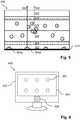
- An exemplary configuration of an LCD layer structure 100 under one pixelis shown in figure 1a .
- the top of the structure 100faces a screen surface (not shown) of the LCD, and the bottom faces a rear cover (not shown) if such is provided; hence, light generally flows upwards in the drawing, towards a viewer (not shown).
- a backlight 110 layeremits the backlight flow for providing the necessary luminance of the screen surface.
- the light from the backlight layer 110is passed to a diffuser 114 through a backlight cavity 112. By virtue of the distance created by the cavity 112, light cones emanating from luminous points of the backlight layer 110 are allowed to widen before the light flow is further smoothened by the diffuser 114.
- the next group of layers 120-138constitute the liquid crystal panel, which is operable to pixel-wise block light, so that images are formed.
- the incident lightis polarised by a rear polariser layer 120.
- the optical activity of the liquid crystal layer 126 -more precisely, the extent to which it changes the polarisation angle of light passing through it - can be varied by applying an electric field over the layer.
- a thin-film transistor (TFT) layer 122is used to govern the amount of charge between different regions of an addressing structure 124 and a common electrode 128.
- the lightis spectrally filtered by red 130, green 132 and blue 134 spectral filters coated on a glass plate 136, and is subsequently repolarised by the front polariser 138.
- Figure 2is a cross section (not to scale) of an edge-lit LCD 200 provided with reference illuminators 216 according to an embodiment of the invention.
- the backlightis generated by section 210, which is bounded on the sides by a housing 204, on its rear side by a rear reflector 202 and is open in the forward direction (upwards in the drawing) towards an image-forming LCD panel 220.
- a light guide 212is optically coupled to an edge-mounted light source 214, which may be a fluorescent tube (extending orthogonally to the plane of the drawing) or an arrangement of LEDs.
- the light guide 212receives light 256 at different angles of incidence, by virtue of the curved reflective surface 254 that optically connects the light source 214 to the light guide 212.
- the refractive index of the light guide 212is chosen in order that a suitable portion 252 of the light ray leaves the guide 212 at each internal reflection.
- the surface of the light guide 212is matte, to ensure that local luminance variations are not too abrupt.
- Light leaving the light guide 212 laterally or rearwardsis recovered by being reflected back from the inside of the housing 204 or the rear reflector 202, both of which are adapted to reflect visible light.
- all light 256 emitted by the light source 214leaves the backlight section in a forwardly direction, towards the LCD panel 220, a rear diffuser 222 of which evens luminance variations out.
- Reference illuminators 216are arranged beneath the light guide 212.
- each reference illuminator 216has a cone-shaped radiation pattern, wherein the cone subtends a solid angle of approximately ⁇ steradians (corresponding to the cone having an apex angle of about 1.14 radians or 33 degrees of arc).
- the light conemay be even narrower, such as 0.8 ⁇ , 0.6 ⁇ or 0.4 ⁇ steradians.
- This embodiment of the inventioncan be varied in accordance with various LCD backlight configurations.
- a translucent sheetthat causes a portion of light travelling tangentially to leave the sheet in the forwardly direction.
- the sheetmay contain particles with a differing refractive index or may comprise a Fresnel pattern. If such translucent sheet, details of which are well known in the art and will be briefly discussed in connection with figure 4 , is combined with a rear reflector to reflect leaking light back, then reference illuminators according to the invention are arranged in a position between the reflector and the sheet.
- the rear reflector 202may be replaced by an absorbing element, such as a dark matte surface.
- the inside of the housing 204may be accomplished as a nonreflective surface, at least in the wavelength range of the reference illuminators 216. Although this measure will slightly decrease the energy efficiency of the LCD, it may lessen measurement noise produced by secondary rays emanating from reflections of the reference illuminators 216. From the construction disclosed above, the skilled person may extract the following principles, which are likely to facilitate adaptation of the invention to other display types:
- the LCD 200may be operated in an interlaced manner.
- the reference illuminatorsmay only be active in a reference mode, wherein the edge-mounted light source 214 is turned off and the liquid-crystal panel 120-138 is blanked (displays white colour), at least in neighbourhoods of the reference illuminators.
- the LCD 200is adapted to be in the display mode, wherein the light source 214 is turned on and the liquid-crystal panel 120-138 displays graphical information.
- the alternation frequency, as well as the durations of the respective modes,may be determined by the skilled person by routine experimentation. The desirable result is a non-flickering image with sufficient luminance.
- Figure 3is a cross-sectional view (not to scale) of a directly lit LCD 300, which generally consists of a backlight section 310 and an LCD panel 320.
- the backlightis generated by a plurality of light sources 314 (typically 100-1000 LEDs adapted to emit in the visible spectrum) arranged in a plane essentially parallel to the screen surface.
- the light sources 314are arranged evenly over the screen surface, preferably in the shape of an array.
- Light beams 354 emitted by the light sources 314travel through a backlight cavity 318 before reaching a first layer of the LCD panel 320, namely a diffuser 322.
- reference illuminators 316are arranged among the light sources 314.
- reference illuminators 316are of a similar type as the light sources 314, so that electrical connections and the like need not be specially adapted.
- the means for controlling the reference illuminators 316may however be different.
- each reference illuminatoris independently controllable.
- the diffuser 322may to a certain extent blur the reference illuminators 316 -just like the light sources 314 are purposefully blurred to create an even screen luminance - so that the corneo-scleral glints become less clear.
- the optic action of available diffuserscan be accurately modelled as a scattering phenomenon, notably Rayleigh scattering, which affects longer wavelengths to a smaller extent than shorter.
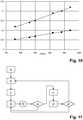
- the problem of blurred reference illuminatorsis much limited if these have a wavelength greater than that of the light sources 314. Measurements have been performed on a commercially available backlight diffuser, and the data given in table 1 below were obtained. Table 1.
- Transmittance of LCD layersas a function of wavelength ( ⁇ ) ⁇ (nm) Transmittance of TFT layer Transmittance of TFT layer and diffuser 780 0.12 0.053 830 0.14 0.064 850 0.15 0.069 910 0.19 0.088 940 0.20 0.091 970 0.22 0.100
- the dataare shown graphically in figure 10 , wherein transmittance values of the TFT layer alone has been indicated by diamonds ( ⁇ ) and those of the TFT layer in combination with a diffuser plate by squares ( ⁇ ).
- ⁇transmittance values of the TFT layer alone has been indicated by diamonds ( ⁇ ) and those of the TFT layer in combination with a diffuser plate by squares ( ⁇ ).
- the reference illuminatorsare preferably near-infrared or infrared LEDs.
- the reference illuminatorsmay be active in phase a) (red) of the cycle, which gives the least wavelength difference, or may be active in the entire cycle. More preferably, however, a four-phase cycle may be devised, as follows:
- FIG 4is a cross-sectional view (not to scale) of an LCD 400 comprising reference illuminators 406 in accordance with the invention.
- the present embodimentexhibits some similar features.
- Backlightis supplied by a light source 414 in a lateral cavity and is conducted by a light guide 416 through a backlight cavity 418 as vertical rays 452, evenly distributed over the extent of the display, which eventually reach a rear diffuser 422, from which the rays are further fed to a liquid-crystal panel above.
- the present light guide 416is wedge-shaped to ensure an even luminance.
- Its top sidemay comprise a pattern of small prisms extending orthogonally to the plane of the drawing, as detailed in US Patent No. 5,797,668 .
- each reference illuminator 406is edge-mounted.
- the light emitted by each reference illuminator 406is focused into a beam by lens 408 and is internally reflected into the transverse (forwardly) direction in a prism 410.
- the triangular cross section of the prism 410has angles of 45 and 90 degrees, the smaller sides facing the reference illuminator and the liquid-crystal panel, respectively.
- a prism 410has a refractive index of at least 1.414.
- the layer comprising the light source 414 and light guide 416may be located beneath the layer of the reference illuminators 406 and the prisms 410.
- the prismsact as reflectors for lateral light rays, the most part of light impinging from below on the hypotenuse will be transmitted through the prism, however with a small change of direction which may affect the luminance of the screen locally.
- the arrangement of edge-mounted reference illuminators 406 and prisms 410 discussed in this paragraphcan also be applied to LCDs having direct backlight and to organic LED displays.
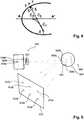
- FIG. 5is a diagrammatic cross-sectional view of an organic LED display 500, which comprises a cathode 504, an emissive layer 506, a conductive layer 508, an anode 510 and a transparent layer 512 for protecting the layers beneath and for supplying mechanical stiffness.
- an organic LED display 500which comprises a cathode 504, an emissive layer 506, a conductive layer 508, an anode 510 and a transparent layer 512 for protecting the layers beneath and for supplying mechanical stiffness.
- light emission in an organic LED displayis caused by electron-hole recombination.
- By applying a potential difference between the cathode 504 and the anode 508, such recombinationis stimulated locally but not very far outside the region of the potential difference.
- graphical informationcan be displayed as a luminous image on the organic LED display screen.
- a plurality of reference illuminators 520are arranged, similarly to, e.g., the display 200 shown in figure 2 .
- the surface 514may be reflective if a brighter display image is desirable, or absorbent if an even luminance is preferred; the latter option will entail less reflections of the reference illuminators 520, which may be harmful to accuracy, as already discussed.
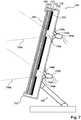
- FIG. 7is a cross-sectional view of an LCD 700 having been equipped with reference illuminators according to the inventive method.
- the LCD 700generally consists of a housing 702 carried by a support 704 adapted to rest on an essentially horizontal surface.
- the LCD 700is adapted to produce a luminous graphical image on a screen surface 706, beneath which translucent layers 708-718 are arranged, such as a diffuser, colour filters, a thin film transistor, a liquid crystal layer and a backlight layer.
- An opaque layeris arranged beneath the translucent layers 708-718.
- the layer 720may be reflective.
- the layer 720is an absorber plate, whereby a more even luminance is achieved.
- reference illuminators 740are provided on the rear side of the LCD 700.
- the reference illuminators 740are supported in a position essentially orthogonal to the screen surface 706 by fastening means 744 attaching them to the rear portion of the housing 702.
- the shape of a light cone 750 emanating from each reference illuminator 740is determined, in part, by a lens 742 provided in front of the illuminator 740.
- the limits of the light cone indicated in figure 7are approximate and may be understood, e.g., as the angle at which the intensity has dropped to half of the maximal value.
- Holes 730, 732are provided in the rear portion of the housing 702 and in the reflector 720, respectively.
- the shape and size of the holes 730, 732correspond to the shape and size of the light cones 750. It is emphasized that the drawing is not to scale, but for clarity the thickness of layers 708-720 has been exaggerated as has the distance between layer 720 and the rear portion of the housing 702; notably, to accommodate the light 750 cones, the width of the holes 730, 732 is disproportionate.
- FIG. 6shows an integrated system 600 for gaze tracking in accordance with an embodiment of the present invention.
- a visual display 602comprises a screen surface 604 adapted to produce a luminous representation of graphical information.
- Reference illuminators 606adapted to emit invisible light (preferably infrared or near-infrared light) are arranged beneath the screen surface 604 in such manner that they are invisible in normal conditions.
- the systemfurther comprises a camera 608 for imaging an eye of a person watching the screen surface 604. The camera is arranged at the lower portion of the visual display 602, so that the line of sight from the camera to each eye is likely to pass below the brow bone and to the side of the nose. Locations of both the pupil centre and glints produced by the reference illuminators 606, the camera 608 is sensitive to both visible light and the light emitted by the reference illuminators 606.
- the reference illuminators 606 and the camera 608are operated in a coordinated manner by a processor (not shown), which is also adapted to compute and output a gaze point of the person based on the data collected by the system 600.
- the operationmay follow the method described in section IV below.
- the gaze point computationmay be based on a spherical or ellipsoidal cornea model, details of which are given below.
- the choice of active reference illuminator(s)may be reassessed repeatedly. For instance, the active illuminator may be selected with the aim of obtaining a glint that is centred with respect to the pupil.
- the system 600may comprise one or more additional sources of invisible (e.g., infrared) light arranged off the optical axis of the camera 608. More particularly, such additional light sources may be arranged on the border of the visual display 602, suitably to the left and/or right of the screen surface 604. As opposed to the reference illuminators 606, the additional light sources provide an evenly distributed intensity rather than concentrated light spots. This facilitates imaging of the eye by increasing the overall illumination of the eye. There is an advantage in using other light sources than the reference illuminators for this, since it may sometimes be impossible to achieve a sufficient overall illumination by means of the the reference illuminators 606 without saturating the light sensor at the glint locations.
- additional sources of invisible (e.g., infrared) lightarranged off the optical axis of the camera 608. More particularly, such additional light sources may be arranged on the border of the visual display 602, suitably to the left and/or right of the screen surface 604. As opposed to the reference illuminators 606, the additional light
- the additional light sourcefar from the optical axis of the sensor, e.g., on the border of the visual display 602, there is a greater probability that the reflection image of this light source falls outside the iris. It is noted that if additional invisible illumination is provided, it may not be required that the camera 608 be sensitive to visible light.
- a bright-pupil light sourceis provided in proximity of the camera 608 and coaxially therewith.
- Such bright-pupil light sourcemay have annular shape and may be arranged around the camera 608. This enables tracking of the eye in both its bright-pupil and dark-pupil condition, which increases the likelihood of being able to choose an illuminator that provides optimal image quality.
- FIG. 9diagrammatically depicts the experimental situation.
- Reference illuminators 912each of which is independently activable, are provided in an object plane 910.
- the illuminators 912are imaged as corneal reflections 926 in the cornea 922 or sclera 924 of a person's eye 920.
- a camera 930which is preferably a digital imaging device, images the corneal reflections 926 as image points 934.
- the imaging of the camera 930is determined by a (rear) nodal point 932 and an image plane.
- An ellipsoid having this shapeis shown in figure 8 , wherein the line AA' represents the x axis and the y direction is vertical on the drawing.
- Points C S and C Tare the respective centres of sagittal and tangential curvature at P .
- a : (0,0)is an umbilical point, at which both radii of curvature are equal to the minimal radius r 0 .
- the calculationsmay be carried out along the lines of the already cited article by Guestrin and Eizenmann, however with certain modifications to account for the aspherical cornea model.
- the locus of a reference illuminator 912is denoted by L
- the nodal point 932 of the camerais denoted by 0
- the image 934 of the corneal reflectionis denoted by U. Because each point P ⁇ A on the cornea has two different radii of curvature in the ellipsoidal model, the article's co-planarity assumption of vectors LO , OU , OC 0 , by which notably each line of equation 15 follows, is no longer valid.
- the inventorshave found empirically that use of an ellipsoidal cornea model leads to a significant increase in accuracy. It has even been observed that pupil-centre tracking is in some cases not necessary as a supplement to glint tracking, as practised hitherto in the art. Indeed, tracking of the cornea - apprehended as an ellipsoidal, rotationally asymmetric surface - provides sufficient information (apart from calibration data such as the angular difference between the optic axis and the visual axis) that the orientation of the eye can be determined. Likewise, the process of calibrating certain parameters, notably the minimal radius of curvature and the eccentricity, can be simplified in so far as the test subject is not required to fix his or her eyes on training points.
- Such improvement of the calibration processis dependent on the correctness of the assumption that the optic axis of the eye coincides with the symmetry axis AA'. Further improvements may be achieved by using a compound light pattern or a time-varying light pattern for generating corneo-scleral glints.
- step a) of the methodan image quality metric is defined.
- the image quality metricmay be based on the quality factors indicated in table 3 below. Table 3.
- Image quality factors NbrPupilsThe number of pupils detected by the camera. Two detected pupils are preferred to one or none.
- GazeDetNoiseIf the test subject fixates a number of visible points in a calibration process, then parameters can be set to such values that the expected divergence from the true point locations is zero.
- the gaze-detection noise after this processcan be expressed as a statistical measure (such as variance, standard deviation, maximal value etc.) of the divergence. A lower gaze-detection noise is preferred.
- PupilContrastThe difference in luminance of a region of the pupil and a region of the iris. Preferably, the regions are located centrally in the pupil and the iris, respectively, and the luminance values are averaged over the regions. A greater pupil contrast is preferred.
- IrisGradient Off-axis regions in a camera's field of viewmay have a lower (effective) resolution than central regions.
- the magnitude of the gradient at the pupil-iris boundaryis taken as a measure of the resolution. A greater magnitude of the gradient is preferred.
- ObstaclesThe pupil-iris boundary may be obscured by the presence of obstacles, such as eye-lashes, non-transparent parts of eye glasses, reflections from eye-glass lenses, glints, eyebrows, nose and the like. It is noted that the most centric glint may lie on the pupil-iris boundary and be detrimental to the pupil finding; in such circumstances, it may be better to use the illuminator that gives the next most centric glint. The absence of obstacles is preferred.
- a signal-to-noise ratiocan be defined by taking PupilContrast (see above) as a measure of the signal intensity and the standard deviation at the centre of the pupil, which is a normally a monochrome region, as a measure of the noise. A higher signal-to-noise ratio is preferred.
- NbrPupils, GazeDetNoise and PupilContrastare the most important, whereas IrisGradient, Obstacles and SNR may be used as additional factors.
- the possible combinations of a camera and an illuminatorfall into two groups: combinations of two coaxial components and combinations of two non-coaxial components.
- the combinations of coaxial componentsare adapted to image the eye(s) in the bright-pupil mode (a retinal retro-reflection complements the iris image), whereas the combinations of non-coaxial components are adapted to image in the dark-pupil mode (a corneo-scleral reflection complements the iris image).
- Step a)is followed by step b), in which either the bright-pupil or the dark-pupil imaging mode is selected.
- step bin which either the bright-pupil or the dark-pupil imaging mode is selected.
- at least one image of the eye in the dark-pupil mode and at least one in the bright-pupil modeare acquired.
- the comparisonis more accurate if the at least two images are acquired closely in time, which also makes the selection process swifter.
- the imagesare acquired simultaneously if possible (that is, if only one bright-pupil image is taken) in this embodiment.
- the imagesare acquired simultaneously.
- the image quality metricis evaluated for these images, and the imaging mode is selected in accordance with the highest value of the metric. If more than one image has been acquired in each mode, then the imaging mode of the image having the globally maximal quality metric is selected.
- step bthe method proceeds to step c), wherein an active camera is selected.
- the image quality metricis evaluated for images acquired using combinations according to the selected imaging mode. Possibly, some images which were used in step b) may be used again.
- the winning quality metric valuedetermines which camera is selected.
- the images for which the image quality factor is assessedmay be acquired while the device is in an evaluation mode.
- an active reference illuminatorto be used in combination with the selected active camera.
- An advantageous way of finding the most suitable reference illuminatoris as follows: using an initially selected reference illuminator the corneo-scleral reflection is retrieved; the deviation from the pupil centre of the reflection is established; it is determined whether there is an alternative reference illuminator which has such position in relation to the initially selected illuminator (is located in a direction opposite the deviation) that a more centric corneo-scleral reflection can be achieved; if such alternative reference illuminator is available, it is selected and the centricity of the corneo-scleral glint is reassessed; if no improvement to the centricity is achieved using the alternative reference illuminator, reversion to the initially selected reference illuminator takes place.
- This proceduremay be refined by taking into account the magnitude of the reflection's deviation from the pupil centre; for instance, a relatively small deviation may not motivate use of an alternative
- step dOn completion of step d), a combination of an active reference illuminator and an active camera has been selected.
- the centricity of the corneo-scleral reflection (step d))is reassessed regularly, and this may provoke a decision to switch to another reference illuminator.
- a delay D of suitable duration(which the skilled person should be able to determine by routine experimentation) is provided between repetitions of step d). The delay causes an intermittent repetition of step d). Choosing a longer delay D eases the computational load, but deteriorates the accuracy of the eye tracker.
- the image quality metricis evaluated for the selected combination, in step e), at regular intervals (such as after every completion of step d) or after every 2 nd , 5 th , 10 th or 20 th completion). If the image quality is greater than or equal to a predetermined level, then the intermittent repetition of step d) is resumed. If however the image quality metric is below the predetermined level although updating of the reference illuminator selection (step d)) has been effected, then the camera selection is revised by repeating steps c) and d).
- step e'the image quality metric is evaluated again. If the image quality metric is still below the predetermined level, then the selection of imaging mode is revised by repeating steps b), c) and d); otherwise, the method resumes the intermittent repetition of step d).
- the arrangement 1200comprises first and second cameras 1210, 1212 and first, second, third and fourth reference illuminators 1220, 1222, 1224 and 1226.
- the combination of camera 1210 and illuminator 1220is coaxial, as is the combination of camera 1212 and illuminator 1222.
- the other six combinationsare non-coaxial.
- the decisions taken during execution of the methodare illustrated in the form of a tree in figure 13 .
- Nodes b1, c1, c2, d1, d2, d3 and d4symbolise decision points; an arrow symbolises a decision to select an imaging mode (on the top level), a camera (on the middle level) or an illuminator (on the lowest level); and the leaves symbolise a complete combination of an active camera and an illuminator, as indicated.
- the first decision point b1is whether to use the bright-pupil (BP) or dark-pupil (DP) imaging mode. If the bright-pupil mode is chosen, the method moves to decision point c1, at which the most suitable of the first camera 1210 and the second camera 1212 is selected. No more decision is taken if the first camera 1210 is selected, for only the first illuminator 1220 is coaxial with the first camera 1210, and likewise, a selection of the second camera 1212 inevitably implies that the combination with the second illuminator 1222 will be used. Hence, decision points d1 and d2 are trivial.
- each choice of an active cameraleads to a choice of three possible reference illuminators (at each of decision points d3 and d4).
- the initial selection of a camera-illuminator combinationis complete.
- the selectionis updated by climbing one level up in the tree.
- the selection of a reference illuminatoris trivial in the case of bright-pupil imaging, but at decision point d3 for instance, there is a choice between the second, third and fourth illuminators 1222, 1224, 1226.
- the second illuminator 1222is likely to give the most centric corneal reflection for tracking a central gaze direction, whereas the third and fourth illuminators 1224, 1226 are probably suitable for lateral gaze directions.
- the switchingmay be performed by a simple control mechanism.
- the middle decision levelis resumed (backwards along the arrows of the decision tree) and possibly the top level as well, should the image quality not have improved sufficiently.
- the method of equipping a visual display with reference illuminators for gaze trackingmay be performed with respect to other visual displays than those mentioned herein, such as a plasma-discharge panel, once the principles of the method have been studied and correctly understood.
- the placement of the reference illuminators in relation to translucent and opaque elements of the displayis a notable example of such principles.
- a computer programmay be stored or distributed on a suitable medium, such as an optical storage medium or a solid-state medium supplied together with or as part of other hardware, but may also be distributed in other forms, such as via the Internet or other wired or wireless telecommunication systems. Any reference signs in the claims should not be construed as limiting the scope.
Landscapes
- Engineering & Computer Science (AREA)
- Physics & Mathematics (AREA)
- General Physics & Mathematics (AREA)
- Theoretical Computer Science (AREA)
- General Engineering & Computer Science (AREA)
- Electromagnetism (AREA)
- Health & Medical Sciences (AREA)
- Human Computer Interaction (AREA)
- Life Sciences & Earth Sciences (AREA)
- Radar, Positioning & Navigation (AREA)
- Computer Networks & Wireless Communication (AREA)
- Remote Sensing (AREA)
- General Health & Medical Sciences (AREA)
- Ophthalmology & Optometry (AREA)
- Medical Informatics (AREA)
- Biophysics (AREA)
- Biomedical Technology (AREA)
- Heart & Thoracic Surgery (AREA)
- Molecular Biology (AREA)
- Surgery (AREA)
- Animal Behavior & Ethology (AREA)
- Public Health (AREA)
- Veterinary Medicine (AREA)
- Multimedia (AREA)
- Devices For Indicating Variable Information By Combining Individual Elements (AREA)
- Eye Examination Apparatus (AREA)
Description
- The invention disclosed herein generally relates to visual display devices having illuminators for facilitating gaze tracking of a viewer of the display. More particularly, a visual display according to the invention may be adapted to assist in gaze tracking using the pupil-centre-corneal-reflection (PCCR) approach.
- In PCCR eye tracking, the gaze vector of an eye is determined on the basis of on an image of the eye when illuminated in such manner that reflections (glints) appear on the cornea. Glint positions and the pupil centre position are extracted from the image using generic computer-vision methods. Methods for computing the gaze vector based on these positions are known in the art, e.g., through the teachings ofE.D. Guestrin and M. Eizenmann in IEEE Transactions on Biomedical Engineering, Vol. 53, No. 6, pp. 1124-1133 (June 2006).
- An important application of PCCR eye-tracking technology is the task of finding the gaze point of a person watching a visual display. Since visual displays are artefacts constructed generally with the aim of providing optimal viewing conditions in terms of luminance, viewing distance and angle, image contrast etc., it might be expected that the measurement accuracy is very high in this situation, particularly when the eye tracking is performed indoors with a controlled ambient illumination. In many practical cases, however, a considerable unreliability is introduced by the difficulty to provide illuminators that are not unsuitably distant from the expected gaze point. Indeed, the reflection created by an oblique illuminator may fall on the sclera, outside the cornea, and since the sclera has spherical shape with respect to the eye's centre of rotation, this reflection is not useful for determining the orientation of the eye.
- In the art, there have been attempts to place illuminators on the display screen surface. Measurements according to this approach may not always give authentic results, because each illuminator acts a visible stimulus and perturbs the natural behaviour of the person.
- Other attempts include arranging illuminators on the border of the visual display, that is, outside the screen surface on which the display is adapted to create visual images. This means that the border cannot be made narrow, contrary to normal aesthetic wishes. This difficulty is accentuated if a two-dimensional array of illuminators is to be provided on each border segment, which is desirable for an accurate two-dimensional position measurement of the cornea. Combining reflections from illuminators arranged on opposing borders of the display is usually not feasible, for it is only in a narrow range of viewing angles, near the centre, that reflections from both borders fall on the cornea.
- Thirdly, interlacing the visual display image with a geometrically distinct reference pattern for creating corneal reflections has been tried. Unless a display dedicated for producing both visible images and an invisible reference pattern is used, the reference pattern is generated by visible light. The interlacing may be performed intermittently during short time intervals, which are synchronised with the intervals for measuring the corneal reflection of the reference pattern. A common difficulty in implementing this approach is that the time intervals, however short, may need to occur rather frequently to achieve sufficient signal power of the reference pattern. Then, because of the time-integrating functioning of the retina, a perceptible superimposed image of the reference pattern may be produced and distract the subject.
- Hence, for gaze tracking in connection with visual displays, there is a need for improved illuminators not suffering from the problems outlined above.
- Two further shortcomings are inherent in many known PCCR implementations. Firstly, the processing involved in finding the pupil centre in an eye image may be problematic. For subjects having a dark iris colour, particularly in the absence of a retinal reflection, the faint pupil-to-iris contrast can make the pupil boundary difficult to discern with a limited computational effort. Secondly, as noted in the already cited article by Guestrin and Eizenmann, the approximation of the cornea as a spherical surface is an important source of errors. Indeed, it has long been known in the art of visual optics that the cornea rather has an ellipsoidal shape, and it would be desirable to achieve improved illuminators for eye-tracking that represent a progress also with respect to these shortcomings.
- Document
US 2003/123027 A1 discloses an eye tracking system using two cameras for capturing images of a user's eye such that the pupil center in each image and a glint resulting from the particular camera's light source can be identified and located in the image plane of the respective camera, wherein the cameras capture images of a test pattern defining a reference coordinate system. - It is an object of the present invention to provide a device and method for facilitating gaze tracking of a person watching a visual display.
- According to a first aspect of the present invention, as defined by the independent claims, there is provided a visual display having reference illuminators adapted to generate corneo-scleral reflections (glints) on an eye watching a screen surface, adapted to display graphical information, of the visual display. The reference illuminators are adapted to emit light outside the visible spectrum, i.e., wavelengths in the range between 380 nm and 750 nm approximately. Moreover, in order that the reference illuminators themselves do not visually distract the eye, they are arranged hidden beneath the screen surface adapted to display graphical information.
- Reference illuminators according to the invention can be used in gaze tracking without introducing unauthentic stimuli, for in normal operating conditions neither the illuminators nor their emitted light are visible to the human eye. The eye image, which is used for computing the gaze point, is acquired by an apparatus sensitive to, at least, light outside the visual spectrum. Advantageously, the reference illuminators are adapted to emit infrared (IR) or near-infrared light. On the one hand, the IR spectrum is adjacent to the visual spectrum, permitting use of existing imaging devices with only minor modifications and limited chromatic aberration. On the other hand, IR light is known not be harmless to the eye, unlike ultraviolet light which is also adjacent to the visible spectrum.
- As a further advantage of the invention, the illuminators can be located in arbitrary positions with respect to the observed screen surface. Many of those skilled in the art of PCCR gaze tracking prefer positioning glint-generating illuminators near the centre of the observed object, in order that glints falling on the sclera in certain viewing angles are avoided. Thus, unlike prior art displays having reference illuminators arranged on the border, the invention allows for optimal positioning of the reference illuminators.
- Clearly, the reference illuminators beneath the screen surface must not be concealed by opaque material, such as a rear reflector layer for enhancing luminance. On the other hand, they must not obstruct the path of visible light rays propagating from beneath (i.e., towards an expected position of a viewer) which produce the graphical information visible on the screen surface. Hence, as the skilled person realises, the desirable position of the reference illuminators is beneath the source of the visible light rays for producing the graphical information, but in front of any opaque objects in the structure of the visual display. Many available visual displays are internally organised as layers arranged parallel with the screen surface. The rear boundary of the last (i.e., deepest) layer that emits visible light and the front boundary of the first (i.e., most superficial) reflecting layer may be contiguous or separated by a small distance. If they are separated, an interstitial space - possibly containing translucent material - is created which may be advantageous in achieving an even screen luminance. It is believed that the skilled person, having studied and understood the present disclosure, may in such circumstances determine the most suitable depth position of the reference illuminators in this interstitial space by routine experimentation.
- The invention can be embodied as visual displays of various kinds, including a liquid crystal display (LCD) and an organic light-emitting diode (LED) display. Embodiments of the invention are directed to both edge-lit LCDs and LCD with direct backlighting. In one embodiment, the liquid crystal panel is synchronised with the backlight and the reference illuminators. When a reference illuminator is active, the liquid crystal panel is 'blanked' (is maximally transmissive, and would produce white colour if was lit) and the backlight is inactive. It is thereby avoided than an occasionally dark portion of the panel blocks one or more reference illuminators.
- In accordance with a second aspect of the present invention, there is provided a method for equipping an LCD with a reference illuminator adapted to emit a beam of invisible light. An LCD susceptible of being equipped according to the method generally comprises the following or equivalent parts: a screen surface, adapted to display graphical information; a plurality of layers, which are translucent or at least operable to be translucent, arranged between the screen surface and essentially parallel with the screen surface; and at least one opaque layer, such as a rear reflector or a rear cover. In order to arrange a reference illuminator in such LCD, a hole is provided in the opaque layer or layers. The illuminator is then mounted, by suitable fastening means, so that its beam will project perpendicularly to the screen surface - or alternatively, in the direction of an expected eye location - and concentrically with respect to the hole. The size and shape of the hole corresponds to the cross section of the beam where it crosses the hole.
- In accordance with a third aspect of the present invention, there is provided a system for determining a gaze point of an eye watching a visual display according to the invention. The system comprises a camera and a processor, which may be physically separate devices or an integrated unit. The display, camera and processor may even be embodied as a single entity. The camera is adapted to acquire an image of the eye including corneo-scleral reflections of the reference illuminators provided at the visual display. The processor is adapted to determine a gaze point using an the inverse of a mapping between a coordinate system in the object plane, which may be the screen surface or its proximity, and a coordinate system in an image plane, in which the eye is imaged. The mapping is a composition of an ellipsoidal reflection mapping (the reflection in the cornea) and a perspective projection (the imaging performed by the camera optics).
- Although the mapping is a priori known as regards its structure, numerical parameters specifying the mapping need to be estimated by comparing the known geometry of the reference illuminator arrangement and the camera image of its reflection in the cornea and/or sclera. The camera parameters, which can be measured in a calibration process, determine the quantitative properties of the perspective projection. Further, the reflection mapping is partially known after calibration, during which the corneal shape of the actual eye has been fitted to an ellipsoid. (As is clear to those skilled in the art, a sphere is the special case of three axes of an ellipsoid being equal; fitting the cornea to a spherical surface may satisfy accuracy requirements in connection with some applications.) Thus, the reflection mapping is defined up to the actual orientation and position of the cornea. The parameters encoding position and orientation are estimated by comparing the known configuration of the reference illuminators with their image in the camera. More precisely, if several reflections are available, the estimation can be based on an analysis of how length ratios and angles change under the mapping.
- In a preferred embodiment of the system for determining a gaze point, the camera is provided near a lower edge of the visual display, e.g., on the frame surrounding the screen surface. Then advantageously, the eye is imaged slightly from below, whereby generally the line of sight is not hindered by protruding brow bones, thick eye-lashes and the like.
- The system for determining a gaze point may be adapted to select what illuminator to use based on the actual glint position. A centrally located glint is generally preferable over one located further out, towards the sclera. In an alternative embodiment, several light sources at one time are used. Then, in principle, more information is available for use in estimation of the orientation of the cornea. As a potential drawback, however, additional reflections may create noise that deteriorates the measurement accuracy.
- In accordance with a fourth aspect of the invention, there is provided a method for determining a gaze point of an eye watching a visual display. The method comprises the following actions:
- providing a visual display comprising a screen surface adapted to display graphical information and including a plurality of reference illuminators arranged beneath said screen surface, the reference illuminators being adapted to emit invisible light;
- providing a camera for acquiring an image of the eye watching the visual display, said image including corneo-scleral reflections of the reference illuminators;
- the eye is illuminated by invisible light from a plurality of reference illuminators provided in an object plane;
- an image of the eye, including corneo-scleral reflections of the reference illuminators, is acquired;
- based on the locations of the corneo-scleral reflections in the image plane, a mapping between a coordinate system in the object plane and a coordinate system in the image plane is defined; and
- based on the mapping, the eye's gaze point in the object coordinate system is determined.
- These and other aspects of the invention will be apparent from and elucidated with reference to the embodiments described hereinafter.
- Embodiments of the present invention will now be described with reference to the accompanying drawings, on which:
figures 1a and 1b are diagrams of the layers in two exemplary LCDs;figure 2 is a cross-sectional view of an edge-lit LCD comprising reference illuminators according to an embodiment of the invention;figure 3 is a cross-sectional view of a LCD with direct backlight, comprising reference illuminators according to an embodiment of the invention;figure 4 is a cross-sectional view of an edge-lit LCD comprising edge-mounted reference illuminators in accordance with an embodiment of the invention;figure 5 is a cross-sectional view of an organic LED display comprising reference illuminators according to an embodiment of the invention;figure 6 shows a system for gaze tracking according to an embodiment of the invention;figure 7 is a cross-sectional view of an LCD having undergone equipping by reference illuminators according to an embodiment of the invention;figure 8 is a diagrammatic cross-sectional view of the cornea;figure 9 is a diagrammatic perspective drawing showing an array of reference illuminators, their corneo-scleral reflection and a camera device adapted to image the eye with said reflection;figure 10 is a plot of the optical transmittance of light at different wavelengths of various layers of an LCD;figure 11 is a flowchart of a method for selecting a combination of a camera and a reference illuminator;figure 12 shows a combined camera and illuminator arrangement; andfigure 13 is an illustration of a decision tree associated with the method for selecting a combination of a camera and a reference illuminator when applied to the combined camera and illuminator arrangement offigure 12 .- In liquid crystal displays (LCDs), a backlight flow is passed through a liquid crystal panel capable of locally attenuating or blocking light that passes through it, wherein the pixels are the smallest sub-regions of the panel that are controllable autonomously. Such an LCD may be capable of producing colour images if the backlight essentially is white (i.e., composed by a plurality of wavelengths) and coloured absorption filters, corresponding to colour components, are arranged in front of individual sub-pixels. An exemplary configuration of an
LCD layer structure 100 under one pixel is shown infigure 1a . The top of thestructure 100 faces a screen surface (not shown) of the LCD, and the bottom faces a rear cover (not shown) if such is provided; hence, light generally flows upwards in the drawing, towards a viewer (not shown). Abacklight 110 layer emits the backlight flow for providing the necessary luminance of the screen surface. The light from thebacklight layer 110 is passed to adiffuser 114 through abacklight cavity 112. By virtue of the distance created by thecavity 112, light cones emanating from luminous points of thebacklight layer 110 are allowed to widen before the light flow is further smoothened by thediffuser 114. The next group of layers 120-138 constitute the liquid crystal panel, which is operable to pixel-wise block light, so that images are formed. Firstly, the incident light is polarised by arear polariser layer 120. The optical activity of the liquid crystal layer 126 - more precisely, the extent to which it changes the polarisation angle of light passing through it - can be varied by applying an electric field over the layer. A thin-film transistor (TFT)layer 122 is used to govern the amount of charge between different regions of an addressingstructure 124 and acommon electrode 128. The light is spectrally filtered by red 130, green 132 and blue 134 spectral filters coated on aglass plate 136, and is subsequently repolarised by thefront polariser 138. Since the transmittance of layers 120-128 can be changed independently under each colour filter 130-134, it is possible to change the apparent colour point (i.e., after mixing the respective contributions from the red, green and blue sub-pixels) of the pixel. Further details on the structure and operation of LCDs may be had from a study of the articleSh. Morozumi, Active-Matrix Thin-Film Transistor Liquid-Crystal Displays, in Advances in Electronics and Electron Physics, Vol. 77 (1990). Figure 2 is a cross section (not to scale) of an edge-litLCD 200 provided with reference illuminators 216 according to an embodiment of the invention. The backlight is generated bysection 210, which is bounded on the sides by ahousing 204, on its rear side by arear reflector 202 and is open in the forward direction (upwards in the drawing) towards an image-formingLCD panel 220. Alight guide 212 is optically coupled to an edge-mountedlight source 214, which may be a fluorescent tube (extending orthogonally to the plane of the drawing) or an arrangement of LEDs. In this embodiment, thelight guide 212 receives light 256 at different angles of incidence, by virtue of the curvedreflective surface 254 that optically connects thelight source 214 to thelight guide 212. The refractive index of thelight guide 212 is chosen in order that asuitable portion 252 of the light ray leaves theguide 212 at each internal reflection. Suitably, the surface of thelight guide 212 is matte, to ensure that local luminance variations are not too abrupt. Light leaving thelight guide 212 laterally or rearwards is recovered by being reflected back from the inside of thehousing 204 or therear reflector 202, both of which are adapted to reflect visible light. Hence, apart from absorption losses, all light 256 emitted by thelight source 214 leaves the backlight section in a forwardly direction, towards theLCD panel 220, arear diffuser 222 of which evens luminance variations out. Reference illuminators 216 are arranged beneath thelight guide 212. Rays 256 of invisible light from the reference illuminators 216 pass through thelight guide 212 under small angles of incidence, and therefore undergo little change as regards their direction and intensity. Preferably, each reference illuminator 216 has a cone-shaped radiation pattern, wherein the cone subtends a solid angle of approximately π steradians (corresponding to the cone having an apex angle of about 1.14 radians or 33 degrees of arc). The light cone may be even narrower, such as 0.8π, 0.6π or 0.4π steradians.- This embodiment of the invention can be varied in accordance with various LCD backlight configurations. E.g., as a light guide one may use (in combination with a suitable edge light source) a translucent sheet that causes a portion of light travelling tangentially to leave the sheet in the forwardly direction. The sheet may contain particles with a differing refractive index or may comprise a Fresnel pattern. If such translucent sheet, details of which are well known in the art and will be briefly discussed in connection with
figure 4 , is combined with a rear reflector to reflect leaking light back, then reference illuminators according to the invention are arranged in a position between the reflector and the sheet. As another variation, therear reflector 202 may be replaced by an absorbing element, such as a dark matte surface. Likewise, the inside of thehousing 204 may be accomplished as a nonreflective surface, at least in the wavelength range of the reference illuminators 216. Although this measure will slightly decrease the energy efficiency of the LCD, it may lessen measurement noise produced by secondary rays emanating from reflections of the reference illuminators 216. From the construction disclosed above, the skilled person may extract the following principles, which are likely to facilitate adaptation of the invention to other display types: - the reference illuminators may not be arranged beneath an opaque layer;
- the reference illuminators may not be arranged so superficially that they are visible to a viewer of the screen in normal conditions; and
- the energy efficiency of the reference illuminators can be increased by being located more superficially, so that a lesser portion of the emitted light is absorbed.
- As a variation to the embodiment shown in
figure 2 , theLCD 200 may be operated in an interlaced manner. Namely, the reference illuminators may only be active in areference mode, wherein the edge-mountedlight source 214 is turned off and the liquid-crystal panel 120-138 is blanked (displays white colour), at least in neighbourhoods of the reference illuminators. When not in this mode, theLCD 200 is adapted to be in thedisplay mode, wherein thelight source 214 is turned on and the liquid-crystal panel 120-138 displays graphical information. The alternation frequency, as well as the durations of the respective modes, may be determined by the skilled person by routine experimentation. The desirable result is a non-flickering image with sufficient luminance. Figure 3 is a cross-sectional view (not to scale) of a directly litLCD 300, which generally consists of abacklight section 310 and anLCD panel 320. The backlight is generated by a plurality of light sources 314 (typically 100-1000 LEDs adapted to emit in the visible spectrum) arranged in a plane essentially parallel to the screen surface. To achieve an even luminance, the light sources 314 are arranged evenly over the screen surface, preferably in the shape of an array. Light beams 354 emitted by the light sources 314 travel through abacklight cavity 318 before reaching a first layer of theLCD panel 320, namely adiffuser 322. In accordance with the invention, reference illuminators 316 (typically 1-10 infrared or near-infrared LEDs) are arranged among the light sources 314. Advantageously, reference illuminators 316 are of a similar type as the light sources 314, so that electrical connections and the like need not be specially adapted. The means for controlling the reference illuminators 316 may however be different. Notably, if the visual display is adapted to be part of an eye tracking system in which one reference illuminator is active at a time or an automated shifting between different reference illuminators is intended, then each reference illuminator is independently controllable. It is noted that thediffuser 322 may to a certain extent blur the reference illuminators 316 -just like the light sources 314 are purposefully blurred to create an even screen luminance - so that the corneo-scleral glints become less clear. However, it has been observed empirically that the optic action of available diffusers can be accurately modelled as a scattering phenomenon, notably Rayleigh scattering, which affects longer wavelengths to a smaller extent than shorter. For this reason, the problem of blurred reference illuminators is much limited if these have a wavelength greater than that of the light sources 314. Measurements have been performed on a commercially available backlight diffuser, and the data given in table 1 below were obtained.Table 1. Transmittance of LCD layers, as a function of wavelength (λ) λ (nm) Transmittance of TFT layer Transmittance of TFT layer and diffuser 780 0.12 0.053 830 0.14 0.064 850 0.15 0.069 910 0.19 0.088 940 0.20 0.091 970 0.22 0.100 figure 10 , wherein transmittance values of the TFT layer alone has been indicated by diamonds (◊) and those of the TFT layer in combination with a diffuser plate by squares (□). Evidently, there is no local transmittance minimum in the studied wavelength interval, and the relation between wavelength increments and transmittance increments is positive and approximately linear. A possible physical explanation is that scattering is responsible for the attenuation at shorter wavelengths. Since scattering decreases with wavelength, transmittance increases. The transmittance of allt the layers in an LCD, as experienced by an 850-nm reference illuminator arranged in accordance with the invention, has been determined empirically to be approximately 0.10 in a representative case. Clearly, the TFT layer accounts for the most important attenuation.- J.-Ch. Wang and J.-L. Lin have reported on a modified directly-lit LCD in their paperThe innovative color LCD by using three color bank scrolling backlights, SPIE Photonics West (January 2009), paper 7232-15. Their modified LCD produces colour images by temporal mixing, as opposed to the spatial mixing between sub-pixels of conventional colour displays. The principle is illustrated in
figure 1b , wherein, compared withfigure 1a , thecoloured absorption filters generic backlight layer 110 has been exchanged for anarray 140 of coloured LEDs having, say, red, green and blue colour. The liquid-crystal panel 120-138 is now operated in a 'scrolling' mode, that is, it alternates cyclically between three phases: - a) red LEDs are active, liquid-crystal panel displays the red image component;
- b) green LEDs are active, liquid-crystal panel displays the green image component; and
- c) blue LEDs are active, liquid-crystal panel displays the blue image component.
- How the invention can be embodied in connection with an LCD modified in accordance with Wang and Lin is illustrated with reference to
figure 3 by assigning a new function to some of the structural elements represented therein, as per table 2 below.Table 2. Reference numerals of figure 3 when showing a modifiedLCD 314a red LED 316a green LED 314b blue LED 316b reference illuminator 314c red LED 316c green LED 314d blue LED 320 cyclically alternating liquid-crystal panelnot containing coloured absorption filters - a') as phase a) above;
- b') as phase b) above;
- c') as phase c) above; and
- d') reference illuminator(s) active, liquid-crystal panel maximally transmissive ('blanked').
Figure 4 is a cross-sectional view (not to scale) of anLCD 400 comprising reference illuminators 406 in accordance with the invention. In relation to theLCD 200 shown infigure 2 , the present embodiment exhibits some similar features. Backlight is supplied by alight source 414 in a lateral cavity and is conducted by alight guide 416 through abacklight cavity 418 asvertical rays 452, evenly distributed over the extent of the display, which eventually reach arear diffuser 422, from which the rays are further fed to a liquid-crystal panel above. In contrast to the light guide 216 offigure 2 , the presentlight guide 416 is wedge-shaped to ensure an even luminance. Its top side may comprise a pattern of small prisms extending orthogonally to the plane of the drawing, as detailed inUS Patent No. 5,797,668 . There is no drawback in using a wedge-shapedlight guide 416 in association with an LCD of the type shown infigure 2 .- In order to achieve a thinner LCD, the reference illuminators 406 are edge-mounted. The light emitted by each reference illuminator 406 is focused into a beam by lens 408 and is internally reflected into the transverse (forwardly) direction in a prism 410. The triangular cross section of the prism 410 has angles of 45 and 90 degrees, the smaller sides facing the reference illuminator and the liquid-crystal panel, respectively. To achieve total internal reflection, a prism 410 has a refractive index of at least 1.414. It may be advantageous, e.g., for mechanical reasons, to arrange the prisms 410 embedded in a sheet of resin or a similar material suitable as a light guide; then, it is the ratio of the prism's refractive index and that of the resin which should not be below 1.414. In an alternative embodiment, the layer comprising the
light source 414 andlight guide 416 may be located beneath the layer of the reference illuminators 406 and the prisms 410. Indeed, although the prisms act as reflectors for lateral light rays, the most part of light impinging from below on the hypotenuse will be transmitted through the prism, however with a small change of direction which may affect the luminance of the screen locally. It is noted that the arrangement of edge-mounted reference illuminators 406 and prisms 410 discussed in this paragraph can also be applied to LCDs having direct backlight and to organic LED displays. Figure 5 is a diagrammatic cross-sectional view of anorganic LED display 500, which comprises acathode 504, anemissive layer 506, aconductive layer 508, ananode 510 and atransparent layer 512 for protecting the layers beneath and for supplying mechanical stiffness. According to a widely embraced theory, light emission in an organic LED display is caused by electron-hole recombination. By applying a potential difference between thecathode 504 and theanode 508, such recombination is stimulated locally but not very far outside the region of the potential difference. Thus, graphical information can be displayed as a luminous image on the organic LED display screen. In alayer 502 beneath thecathode 504, a plurality of reference illuminators 520 are arranged, similarly to, e.g., thedisplay 200 shown infigure 2 . Thesurface 514 may be reflective if a brighter display image is desirable, or absorbent if an even luminance is preferred; the latter option will entail less reflections of the reference illuminators 520, which may be harmful to accuracy, as already discussed.Figure 7 is a cross-sectional view of anLCD 700 having been equipped with reference illuminators according to the inventive method. TheLCD 700 generally consists of ahousing 702 carried by asupport 704 adapted to rest on an essentially horizontal surface. TheLCD 700 is adapted to produce a luminous graphical image on ascreen surface 706, beneath which translucent layers 708-718 are arranged, such as a diffuser, colour filters, a thin film transistor, a liquid crystal layer and a backlight layer. An opaque layer is arranged beneath the translucent layers 708-718. To enhance the brightness of thescreen surface 706, thelayer 720 may be reflective. Alternatively, thelayer 720 is an absorber plate, whereby a more even luminance is achieved. In accordance with the invention, reference illuminators 740 are provided on the rear side of theLCD 700. The reference illuminators 740 are supported in a position essentially orthogonal to thescreen surface 706 by fastening means 744 attaching them to the rear portion of thehousing 702. The shape of alight cone 750 emanating from each reference illuminator 740 is determined, in part, by a lens 742 provided in front of the illuminator 740. The limits of the light cone indicated infigure 7 are approximate and may be understood, e.g., as the angle at which the intensity has dropped to half of the maximal value. Holes 730, 732 are provided in the rear portion of thehousing 702 and in thereflector 720, respectively. The shape and size of the holes 730, 732 correspond to the shape and size of thelight cones 750. It is emphasized that the drawing is not to scale, but for clarity the thickness of layers 708-720 has been exaggerated as has the distance betweenlayer 720 and the rear portion of thehousing 702; notably, to accommodate the light 750 cones, the width of the holes 730, 732 is disproportionate.Figure 6 shows anintegrated system 600 for gaze tracking in accordance with an embodiment of the present invention. Avisual display 602 comprises ascreen surface 604 adapted to produce a luminous representation of graphical information.Reference illuminators 606 adapted to emit invisible light (preferably infrared or near-infrared light) are arranged beneath thescreen surface 604 in such manner that they are invisible in normal conditions. The system further comprises acamera 608 for imaging an eye of a person watching thescreen surface 604. The camera is arranged at the lower portion of thevisual display 602, so that the line of sight from the camera to each eye is likely to pass below the brow bone and to the side of the nose. Locations of both the pupil centre and glints produced by thereference illuminators 606, thecamera 608 is sensitive to both visible light and the light emitted by thereference illuminators 606.- The
reference illuminators 606 and thecamera 608 are operated in a coordinated manner by a processor (not shown), which is also adapted to compute and output a gaze point of the person based on the data collected by thesystem 600. The operation may follow the method described in section IV below. The gaze point computation may be based on a spherical or ellipsoidal cornea model, details of which are given below. As a particular example of coordinated operation of thesystem 600, the choice of active reference illuminator(s) may be reassessed repeatedly. For instance, the active illuminator may be selected with the aim of obtaining a glint that is centred with respect to the pupil. - In an alternative embodiment, the
system 600 may comprise one or more additional sources of invisible (e.g., infrared) light arranged off the optical axis of thecamera 608. More particularly, such additional light sources may be arranged on the border of thevisual display 602, suitably to the left and/or right of thescreen surface 604. As opposed to thereference illuminators 606, the additional light sources provide an evenly distributed intensity rather than concentrated light spots. This facilitates imaging of the eye by increasing the overall illumination of the eye. There is an advantage in using other light sources than the reference illuminators for this, since it may sometimes be impossible to achieve a sufficient overall illumination by means of the thereference illuminators 606 without saturating the light sensor at the glint locations. By arranging the additional light source far from the optical axis of the sensor, e.g., on the border of thevisual display 602, there is a greater probability that the reflection image of this light source falls outside the iris. It is noted that if additional invisible illumination is provided, it may not be required that thecamera 608 be sensitive to visible light. - In yet another embodiment of the
system 600, a bright-pupil light source is provided in proximity of thecamera 608 and coaxially therewith. Such bright-pupil light source may have annular shape and may be arranged around thecamera 608. This enables tracking of the eye in both its bright-pupil and dark-pupil condition, which increases the likelihood of being able to choose an illuminator that provides optimal image quality. - Gaze tracking using an aspherical cornea model, more particularly an ellipsoidal cornea model, will now be outlined.
Figure 9 diagrammatically depicts the experimental situation. Reference illuminators 912, each of which is independently activable, are provided in anobject plane 910. The illuminators 912 are imaged as corneal reflections 926 in thecornea 922 orsclera 924 of a person'seye 920. Acamera 930, which is preferably a digital imaging device, images the corneal reflections 926 as image points 934. In a simplified model, as shown on the drawing, the imaging of thecamera 930 is determined by a (rear)nodal point 932 and an image plane. For clarity, light rays are indicated fromreference illuminators cornea 922 and thecamera 930, which maps each reference illuminator 912 to an image point 934, can be expressed by the following mathematical relationship:
- Proj
- is a perspective projection (which in homogeneous coordinates is a linear mapping) known through camera calibration;
- E
- is an ellipsoid representing the corneal surface, known through personal calibration of the test subject while focusing sample points;
- T
- is a rigid transformation which reflects the actual position and orientation of the ellipsoid;
- X
- is a coordinate vector for an illuminator known through the predetermined illuminator arrangement; and
- X'
- is a coordinate vector for the camera image of the same illuminator.
- A procedure of solving the gaze-detection problem will now be outlined; one of its advantages over gaze detection via a complete estimation of the mappingsProj andReflT(E) is that sufficient information for finding the gaze-point may be obtained with fewer computations and less input data. The ellipsoid E used to model the cornea is more precisely given as a surface of revolution, with respect to the x axis, of the curve

figure 8 , wherein the lineAA' represents thex axis and they direction is vertical on the drawing. In a three-dimensional description, if a lateral coordinatez is included,E is defined by
figure 8 represents the sagittal radius of curvature, which is given by

- The calculations may be carried out along the lines of the already cited article by Guestrin and Eizenmann, however with certain modifications to account for the aspherical cornea model. Following Guestrin and Eizenmann, the locus of a reference illuminator 912 is denoted byL, the
nodal point 932 of the camera is denoted by0 and the image 934 of the corneal reflection is denoted byU. Because each pointP ≠A on the cornea has two different radii of curvature in the ellipsoidal model, the article's co-planarity assumption of vectorsLO ,OU ,OC0 , by which notably each line of equation 15 follows, is no longer valid. In the case of an ellipsoidal cornea model, separate equations are obtained for the tangential and sagittal components of the vectors. SeparatingOU ,LO in sagittal and tangential components by orthogonal projection, as per

CSP ,vS ,wS andCTP ,vT ,wT . The calculations can then be continued in a manner similar to that disclosed in the article. - The inventors have found empirically that use of an ellipsoidal cornea model leads to a significant increase in accuracy. It has even been observed that pupil-centre tracking is in some cases not necessary as a supplement to glint tracking, as practised hitherto in the art. Indeed, tracking of the cornea - apprehended as an ellipsoidal, rotationally asymmetric surface - provides sufficient information (apart from calibration data such as the angular difference between the optic axis and the visual axis) that the orientation of the eye can be determined. Likewise, the process of calibrating certain parameters, notably the minimal radius of curvature and the eccentricity, can be simplified in so far as the test subject is not required to fix his or her eyes on training points. Such improvement of the calibration process is dependent on the correctness of the assumption that the optic axis of the eye coincides with the symmetry axisAA'. Further improvements may be achieved by using a compound light pattern or a time-varying light pattern for generating corneo-scleral glints.
- With reference to
figure 11 , a preferred embodiment of a method for selecting a combination of an active camera and an active reference illuminator will be described. The selection is made from a plurality of reference illuminators adapted to illuminate at least one eye and a plurality of cameras adapted to image the eye or eyes with the aim of selecting that combination which provides the most suitable conditions for gaze tracking of the eye(s). In step a) of the method, an image quality metric is defined. The image quality metric may be based on the quality factors indicated in table 3 below.Table 3. Image quality factors NbrPupils The number of pupils detected by the camera. Two detected pupils are preferred to one or none. GazeDetNoise If the test subject fixates a number of visible points in a calibration process, then parameters can be set to such values that the expected divergence from the true point locations is zero. The gaze-detection noise after this process can be expressed as a statistical measure (such as variance, standard deviation, maximal value etc.) of the divergence. A lower gaze-detection noise is preferred. PupilContrast The difference in luminance of a region of the pupil and a region of the iris. Preferably, the regions are located centrally in the pupil and the iris, respectively, and the luminance values are averaged over the regions. A greater pupil contrast is preferred. IrisGradient Off-axis regions in a camera's field of view may have a lower (effective) resolution than central regions. The magnitude of the gradient at the pupil-iris boundary is taken as a measure of the resolution. A greater magnitude of the gradient is preferred. Obstacles The pupil-iris boundary may be obscured by the presence of obstacles, such as eye-lashes, non-transparent parts of eye glasses, reflections from eye-glass lenses, glints, eyebrows, nose and the like. It is noted that the most centric glint may lie on the pupil-iris boundary and be detrimental to the pupil finding; in such circumstances, it may be better to use the illuminator that gives the next most centric glint. The absence of obstacles is preferred. SNR A signal-to-noise ratio can be defined by taking PupilContrast (see above) as a measure of the signal intensity and the standard deviation at the centre of the pupil, which is a normally a monochrome region, as a measure of the noise. A higher signal-to-noise ratio is preferred. - Out of these quality factors, the inventors deem NbrPupils, GazeDetNoise and PupilContrast to be the most important, whereas IrisGradient, Obstacles and SNR may be used as additional factors. The image quality factors may be combined into a total quality metric as per:

- Upon completion of step b), the method proceeds to step c), wherein an active camera is selected. The image quality metric is evaluated for images acquired using combinations according to the selected imaging mode. Possibly, some images which were used in step b) may be used again. The winning quality metric value determines which camera is selected. In this step, just like in step b), the images for which the image quality factor is assessed may be acquired while the device is in an evaluation mode.
- It remains to select, in step d), an active reference illuminator to be used in combination with the selected active camera. An advantageous way of finding the most suitable reference illuminator is as follows: using an initially selected reference illuminator the corneo-scleral reflection is retrieved; the deviation from the pupil centre of the reflection is established; it is determined whether there is an alternative reference illuminator which has such position in relation to the initially selected illuminator (is located in a direction opposite the deviation) that a more centric corneo-scleral reflection can be achieved; if such alternative reference illuminator is available, it is selected and the centricity of the corneo-scleral glint is reassessed; if no improvement to the centricity is achieved using the alternative reference illuminator, reversion to the initially selected reference illuminator takes place. This procedure may be refined by taking into account the magnitude of the reflection's deviation from the pupil centre; for instance, a relatively small deviation may not motivate use of an alternative reference illuminator.
- On completion of step d), a combination of an active reference illuminator and an active camera has been selected. The centricity of the corneo-scleral reflection (step d)) is reassessed regularly, and this may provoke a decision to switch to another reference illuminator. To avoid too frequent reassessment of the centricity, a delay D of suitable duration (which the skilled person should be able to determine by routine experimentation) is provided between repetitions of step d). The delay causes an intermittent repetition of step d). Choosing a longer delay D eases the computational load, but deteriorates the accuracy of the eye tracker. It is also possible to provide a delay D with adaptive duration, which reflects empirically observed human eye-movement patterns, such as saccadic movements. To maintain a high image quality, the image quality metric is evaluated for the selected combination, in step e), at regular intervals (such as after every completion of step d) or after every 2nd, 5th, 10th or 20th completion). If the image quality is greater than or equal to a predetermined level, then the intermittent repetition of step d) is resumed. If however the image quality metric is below the predetermined level although updating of the reference illuminator selection (step d)) has been effected, then the camera selection is revised by repeating steps c) and d). Immediately after such repetition, in step e'), the image quality metric is evaluated again. If the image quality metric is still below the predetermined level, then the selection of imaging mode is revised by repeating steps b), c) and d); otherwise, the method resumes the intermittent repetition of step d).
- With reference to
figure 13 , an application of the described method to thearrangement 1200 shown infigure 12 will now be outlined. Thearrangement 1200 comprises first andsecond cameras fourth reference illuminators camera 1210 andilluminator 1220 is coaxial, as is the combination ofcamera 1212 andilluminator 1222. The other six combinations are non-coaxial. The decisions taken during execution of the method are illustrated in the form of a tree infigure 13 . Nodes b1, c1, c2, d1, d2, d3 and d4 symbolise decision points; an arrow symbolises a decision to select an imaging mode (on the top level), a camera (on the middle level) or an illuminator (on the lowest level); and the leaves symbolise a complete combination of an active camera and an illuminator, as indicated. - Assuming an image quality metric has been defined the first decision point b1 is whether to use the bright-pupil (BP) or dark-pupil (DP) imaging mode. If the bright-pupil mode is chosen, the method moves to decision point c1, at which the most suitable of the
first camera 1210 and thesecond camera 1212 is selected. No more decision is taken if thefirst camera 1210 is selected, for only thefirst illuminator 1220 is coaxial with thefirst camera 1210, and likewise, a selection of thesecond camera 1212 inevitably implies that the combination with thesecond illuminator 1222 will be used. Hence, decision points d1 and d2 are trivial. If instead the dark-pupil mode is selected (at decision point b1), each choice of an active camera (at decision point c2) leads to a choice of three possible reference illuminators (at each of decision points d3 and d4). When the method has reached one of the leaves in the decision tree, the initial selection of a camera-illuminator combination is complete. - The selection is updated by climbing one level up in the tree. As noted, the selection of a reference illuminator is trivial in the case of bright-pupil imaging, but at decision point d3 for instance, there is a choice between the second, third and
fourth illuminators second illuminator 1222 is likely to give the most centric corneal reflection for tracking a central gaze direction, whereas the third andfourth illuminators - While the invention has been illustrated and described in detail in the drawings and foregoing description, such illustration and description are to be considered illustrative or exemplary and not restrictive; the invention is not limited to the disclosed embodiments. For example, the method of equipping a visual display with reference illuminators for gaze tracking may be performed with respect to other visual displays than those mentioned herein, such as a plasma-discharge panel, once the principles of the method have been studied and correctly understood. The placement of the reference illuminators in relation to translucent and opaque elements of the display is a notable example of such principles.
- Other variations to the disclosed embodiments can be understood and effectuated by those skilled in the art in practicing the claimed invention, from a study of the drawings, the disclosure, and the appended claims. In the claims, the word 'comprising' does not exclude other elements or steps, and the indefinite article 'a' or 'an' does not exclude a plurality. A single processor or other unit may fulfil the functions of several items received in the claims. The mere fact that certain measures are recited in mutually different dependent claims does not indicate that a combination of these measured cannot be used to advantage. A computer program may be stored or distributed on a suitable medium, such as an optical storage medium or a solid-state medium supplied together with or as part of other hardware, but may also be distributed in other forms, such as via the Internet or other wired or wireless telecommunication systems. Any reference signs in the claims should not be construed as limiting the scope.


Claims (14)
- A system (600) for determining a gaze point of an eye, comprising:a visual display (602) comprising a screen surface (604) adapted to display graphical information and includes a plurality of reference illuminators (606) arranged beneath said screen surface (604), the reference illuminators (606) being adapted to emit invisible light;a camera (608) for acquiring an image of the eye watching the visual display (602), said image including corneo-scleral reflections of the reference illuminators (606); anda processor adapted to:define, based on the locations of the corneo-scleral reflections in the image plane, a mapping between a coordinate system in the object plane and a coordinate system in the image plane; anddetermine, based on the mapping, the eye's gaze point in the object plane coordinate system,wherein the mapping is composed of an ellipsoidal reflection mapping and a perspective projection.
- The system (600) according to claim 1, wherein the camera (608) is arranged near a lower edge of a screen surface (604) of the visual display (602).
- The system (600) according to claim 1 or 2, wherein the reference illuminators (606) of said visual display (602) are adapted to emit infrared or near-infrared light.
- The system (600) according to claim 1 - 3, wherein the light cone of each reference illuminator (606) of said visual display (602) is essentially normal to the screen surface (604) and subtends a solid angle of at most π steradians.
- The system (600) according to any one of the preceding claims, wherein the reference illuminators (606) of said visual display (602) are arranged in a two-dimensional array, said array being parallel to the screen surface (604).
- The system (600) according to any one of the preceding claims, wherein said visual display (602) further comprises a plurality of layers provided beneath the screen surface (604) and essentially parallel therewith, wherein any layer being arranged between the reference illuminators (606) and the screen surface (604) is operable to be translucent.
- The system (600) according to any one of the preceding claims, wherein said visual display (602) is a liquid crystal display comprising a light guide, which is optically coupled to an edge-mounted backlight illuminator, and a rear reflector layer, between which layers the reference illuminators (606) are arranged.
- The system (600) according to any one of claims 1 - 6, wherein said visual display (602) is a liquid crystal display comprising direct backlight illuminators, wherein a subset of the backlight illuminators are reference illuminators (606).
- The system (600) according to claim 7 or 8, further comprising a liquid crystal panel with variable transmittance, said display being alternately operable in:a display mode, wherein at least some backlight illuminator is active; andan reference mode, wherein the reference illuminators (606) are active, all backlight illuminators for emitting visible light is inactive, and the liquid crystal panel has maximal transmittance.
- The system (600) according to any one of claims 1 - 6, wherein said visual display (602) is an organic light-emitting diode display comprising a translucent anode layer, a conductive layer, an emissive layer and a translucent cathode layer, beneath which layers the reference illuminators (606) are arranged.
- The system (600) according to any one of the preceding claims, wherein the reference illuminators (606) of said visual display (602) are adapted to illuminate an eye watching the visual display (602), which eye is subject to gaze tracking.
- A method for determining a gaze point of an eye watching a visual display (602) comprising the steps of:a) providing a visual display (602) comprising a screen surface (604) adapted to display graphical information and including a plurality of reference illuminators (606) arranged beneath said screen surface (604), the reference illuminators (606) being adapted to emit invisible light; providing a camera (608) for acquiring an image of the eye watching the visual display (602), said image including corneo-scleral reflections of the reference illuminators (606);b) illuminating the eye by invisible light from a plurality of reference illuminators (606) provided in an object plane;c) acquiring an image of the eye including corneo-scleral reflections of the reference illuminators (606);d) defining, based on the locations of the corneo-scleral reflections in the image plane, a mapping between a coordinate system in the object plane and a coordinate system in the image plane; ande) determining, based on the mapping, the eye's gaze point in the object coordinate system,said methodcharacterised in that the mapping is composed of an ellipsoidal reflection mapping and a perspective projection.
- The method of claim 12, wherein the ellipsoidal reflection mapping is a prolate spherical reflection mapping.
- The method according to claim 12 or 13, wherein the reference illuminators (606) are arranged beneath a screen surface (604), adapted to display graphical information, of the visual display (602).
Priority Applications (9)
| Application Number | Priority Date | Filing Date | Title |
|---|---|---|---|
| ES09157106TES2880475T3 (en) | 2009-04-01 | 2009-04-01 | Visual representation system with illuminators for gaze tracking |
| EP09157106.7AEP2236074B1 (en) | 2009-04-01 | 2009-04-01 | Visual display with illuminators for gaze tracking |
| US12/750,967US8220926B2 (en) | 2009-04-01 | 2010-03-31 | Visual display with illuminators for gaze tracking |
| US13/465,245US8562136B2 (en) | 2009-04-01 | 2012-05-07 | Visual display with illuminators for gaze tracking |
| US14/030,111US9244170B2 (en) | 2009-04-01 | 2013-09-18 | Visual display with illuminators for gaze tracking |
| US14/585,586US9194952B2 (en) | 2009-04-01 | 2014-12-30 | Visual display with illuminators for gaze tracking |
| US15/005,198US9632180B2 (en) | 2009-04-01 | 2016-01-25 | Visual display with illuminators for gaze tracking |
| US15/483,298US10191542B2 (en) | 2009-04-01 | 2017-04-10 | Visual display with illuminators for gaze tracking |
| US16/229,165US20190302882A1 (en) | 2009-04-01 | 2018-12-21 | Visual display with illuminators for gaze tracking |
Applications Claiming Priority (1)
| Application Number | Priority Date | Filing Date | Title |
|---|---|---|---|
| EP09157106.7AEP2236074B1 (en) | 2009-04-01 | 2009-04-01 | Visual display with illuminators for gaze tracking |
Publications (2)
| Publication Number | Publication Date |
|---|---|
| EP2236074A1 EP2236074A1 (en) | 2010-10-06 |
| EP2236074B1true EP2236074B1 (en) | 2021-05-26 |
Family
ID=40910753
Family Applications (1)
| Application Number | Title | Priority Date | Filing Date |
|---|---|---|---|
| EP09157106.7AActiveEP2236074B1 (en) | 2009-04-01 | 2009-04-01 | Visual display with illuminators for gaze tracking |
Country Status (3)
| Country | Link |
|---|---|
| US (6) | US8220926B2 (en) |
| EP (1) | EP2236074B1 (en) |
| ES (1) | ES2880475T3 (en) |
Families Citing this family (114)
| Publication number | Priority date | Publication date | Assignee | Title |
|---|---|---|---|---|
| US10039445B1 (en) | 2004-04-01 | 2018-08-07 | Google Llc | Biosensors, communicators, and controllers monitoring eye movement and methods for using them |
| US8750578B2 (en) | 2008-01-29 | 2014-06-10 | DigitalOptics Corporation Europe Limited | Detecting facial expressions in digital images |
| US20190302882A1 (en)* | 2009-04-01 | 2019-10-03 | Tobii Ab | Visual display with illuminators for gaze tracking |
| EP2238889B1 (en) | 2009-04-01 | 2011-10-12 | Tobii Technology AB | Adaptive camera and illuminator eyetracker |
| EP2236074B1 (en) | 2009-04-01 | 2021-05-26 | Tobii AB | Visual display with illuminators for gaze tracking |
| US8890946B2 (en) | 2010-03-01 | 2014-11-18 | Eyefluence, Inc. | Systems and methods for spatially controlled scene illumination |
| EP2549914B1 (en)* | 2010-03-22 | 2019-06-05 | Koninklijke Philips N.V. | System and method for tracking the point of gaze of an observer |
| US9405364B2 (en) | 2010-10-29 | 2016-08-02 | IT-Universitetet i København | Method of determining reflections of light |
| US8836777B2 (en)* | 2011-02-25 | 2014-09-16 | DigitalOptics Corporation Europe Limited | Automatic detection of vertical gaze using an embedded imaging device |
| US8885877B2 (en) | 2011-05-20 | 2014-11-11 | Eyefluence, Inc. | Systems and methods for identifying gaze tracking scene reference locations |
| US8911087B2 (en) | 2011-05-20 | 2014-12-16 | Eyefluence, Inc. | Systems and methods for measuring reactions of head, eyes, eyelids and pupils |
| US9239142B2 (en)* | 2011-06-14 | 2016-01-19 | Osram Sylvania Inc. | Edge-lit light fixture incorporating a downlight and having a uniform external appearance |
| US8929589B2 (en) | 2011-11-07 | 2015-01-06 | Eyefluence, Inc. | Systems and methods for high-resolution gaze tracking |
| DE102011055967B4 (en)* | 2011-12-02 | 2016-03-10 | Seereal Technologies S.A. | Measuring method and device for carrying out the measuring method |
| US8955973B2 (en)* | 2012-01-06 | 2015-02-17 | Google Inc. | Method and system for input detection using structured light projection |
| CN104159498A (en)* | 2012-01-10 | 2014-11-19 | 迪吉塔尔视觉有限责任公司 | A refractometer with a remote wavefront generator |
| EP2658250A1 (en)* | 2012-04-26 | 2013-10-30 | Sony Mobile Communications AB | Screen camera |
| KR20130121303A (en)* | 2012-04-27 | 2013-11-06 | 한국전자통신연구원 | System and method for gaze tracking at a distance |
| EP2826414B1 (en)* | 2012-07-31 | 2016-11-30 | Japan Science and Technology Agency | Point-of-gaze detection device, point-of-gaze detection method, personal parameter calculating device, personal parameter calculating method, program, and computer-readable storage medium |
| US9575960B1 (en)* | 2012-09-17 | 2017-02-21 | Amazon Technologies, Inc. | Auditory enhancement using word analysis |
| US9612656B2 (en) | 2012-11-27 | 2017-04-04 | Facebook, Inc. | Systems and methods of eye tracking control on mobile device |
| US9265458B2 (en) | 2012-12-04 | 2016-02-23 | Sync-Think, Inc. | Application of smooth pursuit cognitive testing paradigms to clinical drug development |
| SE536990C2 (en)* | 2013-01-22 | 2014-11-25 | Crunchfish Ab | Improved tracking of an object for controlling a non-touch user interface |
| US9699433B2 (en) | 2013-01-24 | 2017-07-04 | Yuchen Zhou | Method and apparatus to produce re-focusable vision with detecting re-focusing event from human eye |
| US9380976B2 (en) | 2013-03-11 | 2016-07-05 | Sync-Think, Inc. | Optical neuroinformatics |
| GB2511868B (en)* | 2013-03-15 | 2020-07-15 | Tobii Ab | Eye/gaze tracker and method of tracking the position of an eye and/or a gaze point of a subject |
| US20140313308A1 (en)* | 2013-04-19 | 2014-10-23 | Samsung Electronics Co., Ltd. | Apparatus and method for tracking gaze based on camera array |
| EP2995241B1 (en)* | 2013-05-08 | 2021-04-14 | National University Corporation Shizuoka University | Pupil detection light source device, pupil detection device and pupil detection method |
| JP6265348B2 (en) | 2013-05-22 | 2018-01-24 | 国立大学法人神戸大学 | Eye-gaze measuring device, eye-gaze measuring method, and eye-gaze measuring program |
| US9113036B2 (en)* | 2013-07-17 | 2015-08-18 | Ebay Inc. | Methods, systems, and apparatus for providing video communications |
| CN103366381A (en)* | 2013-08-06 | 2013-10-23 | 山东大学 | Sight line tracking correcting method based on space position |
| CN113576398A (en) | 2013-09-03 | 2021-11-02 | 托比股份公司 | Portable eye tracking device |
| US10310597B2 (en) | 2013-09-03 | 2019-06-04 | Tobii Ab | Portable eye tracking device |
| US10686972B2 (en) | 2013-09-03 | 2020-06-16 | Tobii Ab | Gaze assisted field of view control |
| WO2015038810A2 (en) | 2013-09-11 | 2015-03-19 | Firima Inc. | User interface based on optical sensing and tracking of user's eye movement and position |
| WO2015048030A1 (en) | 2013-09-24 | 2015-04-02 | Sony Computer Entertainment Inc. | Gaze tracking variations using visible lights or dots |
| US9781360B2 (en)* | 2013-09-24 | 2017-10-03 | Sony Interactive Entertainment Inc. | Gaze tracking variations using selective illumination |
| US9468373B2 (en) | 2013-09-24 | 2016-10-18 | Sony Interactive Entertainment Inc. | Gaze tracking variations using dynamic lighting position |
| CN106132284B (en)* | 2013-11-09 | 2019-03-22 | 深圳市汇顶科技股份有限公司 | optical eye tracking |
| CN106663183B (en) | 2013-11-27 | 2020-04-24 | 深圳市汇顶科技股份有限公司 | Eye tracking and user response detection |
| US10017114B2 (en) | 2014-02-19 | 2018-07-10 | Magna Electronics Inc. | Vehicle vision system with display |
| JP6256165B2 (en)* | 2014-04-09 | 2018-01-10 | 富士通株式会社 | Gaze detection device, gaze detection program, and gaze detection method |
| EP3137968B1 (en) | 2014-04-29 | 2019-10-16 | Hewlett-Packard Development Company, L.P. | Gaze detector using reference frames in media |
| US20150346814A1 (en)* | 2014-05-30 | 2015-12-03 | Vaibhav Thukral | Gaze tracking for one or more users |
| US9678567B2 (en) | 2014-07-16 | 2017-06-13 | Avaya Inc. | Indication of eye tracking information during real-time communications |
| JP6547268B2 (en)* | 2014-10-02 | 2019-07-24 | 富士通株式会社 | Eye position detection device, eye position detection method and eye position detection program |
| CN104391574A (en)* | 2014-11-14 | 2015-03-04 | 京东方科技集团股份有限公司 | Sight processing method, sight processing system, terminal equipment and wearable equipment |
| US9405120B2 (en) | 2014-11-19 | 2016-08-02 | Magna Electronics Solutions Gmbh | Head-up display and vehicle using the same |
| CN107111863B (en)* | 2014-12-10 | 2020-11-17 | 瑞典爱立信有限公司 | Apparatus and method for corneal imaging |
| WO2016097919A1 (en) | 2014-12-16 | 2016-06-23 | Koninklijke Philips N.V. | Gaze tracking system with calibration improvement, accuracy compensation, and gaze localization smoothing |
| RU2596062C1 (en) | 2015-03-20 | 2016-08-27 | Автономная Некоммерческая Образовательная Организация Высшего Профессионального Образования "Сколковский Институт Науки И Технологий" | Method for correction of eye image using machine learning and method of machine learning |
| US10043281B2 (en) | 2015-06-14 | 2018-08-07 | Sony Interactive Entertainment Inc. | Apparatus and method for estimating eye gaze location |
| US10061383B1 (en)* | 2015-09-16 | 2018-08-28 | Mirametrix Inc. | Multi-feature gaze tracking system and method |
| US10475418B2 (en) | 2015-10-26 | 2019-11-12 | Reald Spark, Llc | Intelligent privacy system, apparatus, and method thereof |
| US10324297B2 (en) | 2015-11-30 | 2019-06-18 | Magna Electronics Inc. | Heads up display system for vehicle |
| CN114143495B (en) | 2016-01-05 | 2025-07-15 | 瑞尔D斯帕克有限责任公司 | Gaze Correction for Multi-View Images |
| US10401621B2 (en) | 2016-04-19 | 2019-09-03 | Magna Electronics Inc. | Display unit for vehicle head-up display system |
| EP3458897B1 (en) | 2016-05-19 | 2025-04-02 | RealD Spark, LLC | Wide angle imaging directional backlights |
| US10425635B2 (en) | 2016-05-23 | 2019-09-24 | Reald Spark, Llc | Wide angle imaging directional backlights |
| CN106405933B (en)* | 2016-10-31 | 2019-08-13 | 京东方科技集团股份有限公司 | Backlight module and liquid crystal display device |
| WO2018129059A1 (en) | 2017-01-04 | 2018-07-12 | Reald Spark, Llc | Optical stack for imaging directional backlights |
| EP3607387A4 (en) | 2017-04-03 | 2020-11-25 | RealD Spark, LLC | Segmented imaging directional backlights |
| US10126575B1 (en) | 2017-05-08 | 2018-11-13 | Reald Spark, Llc | Optical stack for privacy display |
| US20210199879A1 (en) | 2017-05-08 | 2021-07-01 | Reald Spark, Llc | Optical stack for imaging directional backlights |
| CN116841075A (en) | 2017-05-08 | 2023-10-03 | 瑞尔D斯帕克有限责任公司 | Optical stack for directional display |
| CN111183405A (en) | 2017-08-08 | 2020-05-19 | 瑞尔D斯帕克有限责任公司 | Adjust the digital representation of the head area |
| US10976811B2 (en)* | 2017-08-11 | 2021-04-13 | Microsoft Technology Licensing, Llc | Eye-tracking with MEMS scanning and reflected light |
| TWI878209B (en) | 2017-09-15 | 2025-04-01 | 美商瑞爾D斯帕克有限責任公司 | Display device and a view angle control optical element for application to a display device |
| US10948648B2 (en) | 2017-09-29 | 2021-03-16 | Reald Spark, Llc | Backlights having stacked waveguide and optical components with different coefficients of friction |
| WO2019090246A1 (en) | 2017-11-06 | 2019-05-09 | Reald Spark, Llc | Privacy display apparatus |
| AU2018267553B2 (en)* | 2017-11-20 | 2019-08-22 | Ashok Krishnan | Systems and methods to train vehicles |
| US10474916B2 (en) | 2017-11-20 | 2019-11-12 | Ashok Krishnan | Training of vehicles to improve autonomous capabilities |
| KR102759510B1 (en) | 2018-01-25 | 2025-02-04 | 리얼디 스파크, 엘엘씨 | Touchscreen for privacy display |
| US10976578B2 (en) | 2018-01-25 | 2021-04-13 | Reald Spark, Llc | Reflective optical stack for privacy display |
| EP3769516B1 (en) | 2018-03-22 | 2025-06-25 | RealD Spark, LLC | Optical waveguide for directional backlight |
| US10534982B2 (en)* | 2018-03-30 | 2020-01-14 | Tobii Ab | Neural network training for three dimensional (3D) gaze prediction with calibration parameters |
| US10725538B2 (en) | 2018-06-19 | 2020-07-28 | Igt | Interacting with game elements using eye movement tracking |
| US11079645B2 (en) | 2018-06-29 | 2021-08-03 | Reald Spark, Llc | Stabilization for privacy display |
| WO2020018552A1 (en) | 2018-07-18 | 2020-01-23 | Reald Spark, Llc | Optical stack for switchable directional display |
| TWI704501B (en)* | 2018-08-09 | 2020-09-11 | 宏碁股份有限公司 | Electronic apparatus operated by head movement and operation method thereof |
| CN112740093B (en)* | 2018-09-21 | 2024-03-08 | 杜比实验室特许公司 | Bonding component within an optical stack of a head-mounted device |
| US11106103B2 (en) | 2018-10-03 | 2021-08-31 | Reald Spark, Llc | Privacy display apparatus controlled in response to environment of apparatus |
| US11092852B2 (en) | 2018-11-07 | 2021-08-17 | Reald Spark, Llc | Directional display apparatus |
| SE1851597A1 (en)* | 2018-12-17 | 2020-06-02 | Tobii Ab | Gaze tracking via tracing of light paths |
| CN113228154A (en)* | 2018-12-25 | 2021-08-06 | 堺显示器制品株式会社 | Corrected image generation system, image control program, and recording medium |
| US11287677B2 (en) | 2019-01-07 | 2022-03-29 | Reald Spark, Llc | Optical stack for privacy display |
| US11326763B1 (en) | 2019-02-06 | 2022-05-10 | Apple Inc. | Light-emitting diodes with optical filters |
| US11861941B1 (en)* | 2019-02-06 | 2024-01-02 | Apple Inc. | Eye camera systems with polarized light |
| US11029566B2 (en) | 2019-02-12 | 2021-06-08 | Reald Spark, Llc | Diffuser for privacy display |
| TW202102883A (en) | 2019-07-02 | 2021-01-16 | 美商瑞爾D斯帕克有限責任公司 | Directional display apparatus |
| WO2021026018A1 (en) | 2019-08-02 | 2021-02-11 | Reald Spark, Llc | Optical stack for privacy display |
| EP4038605B1 (en) | 2019-10-02 | 2024-09-25 | RealD Spark, LLC | Privacy display apparatus |
| US11627262B2 (en) | 2019-11-04 | 2023-04-11 | Fotonation Limited | Handheld computing device |
| US11733578B2 (en) | 2019-11-13 | 2023-08-22 | ReaID Spark, LLC | Display device with uniform off-axis luminance reduction |
| CN114761844A (en) | 2019-12-10 | 2022-07-15 | 瑞尔D斯帕克有限责任公司 | Control of reflection of display device |
| WO2021126707A1 (en) | 2019-12-18 | 2021-06-24 | Reald Spark, Llc | Control of ambient light for a privacy display |
| US11828944B1 (en) | 2020-04-09 | 2023-11-28 | Apple Inc. | Head-mounted device with optical module illumination systems |
| WO2021222598A1 (en) | 2020-04-30 | 2021-11-04 | Reald Spark, Llc | Directional display apparatus |
| WO2021222606A1 (en) | 2020-04-30 | 2021-11-04 | Reald Spark, Llc | Directional display apparatus |
| US11353752B2 (en) | 2020-04-30 | 2022-06-07 | Reald Spark, Llc | Directional display apparatus |
| US11966048B1 (en) | 2020-07-09 | 2024-04-23 | Apple Inc. | Head-mounted devices with dual gaze tracking systems |
| EP4181762A4 (en)* | 2020-07-15 | 2024-07-24 | Magic Leap, Inc. | Eye tracking using aspheric cornea model |
| EP4189447A4 (en) | 2020-07-29 | 2024-07-31 | RealD Spark, LLC | Pupillated illumination apparatus |
| EP4189285A4 (en) | 2020-07-29 | 2024-07-24 | RealD Spark, LLC | REAR LIGHTING FOR A SWITCHABLE DIRECTION INDICATOR |
| US11928257B2 (en)* | 2021-02-17 | 2024-03-12 | Samsung Electronics Co., Ltd. | Method and electronic device for tracking eye |
| US11503998B1 (en) | 2021-05-05 | 2022-11-22 | Innodem Neurosciences | Method and a system for detection of eye gaze-pattern abnormalities and related neurological diseases |
| US11397465B1 (en)* | 2021-05-17 | 2022-07-26 | Microsoft Technology Licensing, Llc | Glint-based eye tracker illumination using dual-sided and dual-layered architectures |
| CN113867526B (en)* | 2021-09-17 | 2024-07-19 | 深显科技(南京)有限责任公司 | Optimized display method, device, equipment and medium based on eye tracking |
| US11861805B2 (en)* | 2021-09-22 | 2024-01-02 | Sony Group Corporation | Eyeball positioning for 3D head modeling |
| US11892717B2 (en) | 2021-09-30 | 2024-02-06 | Reald Spark, Llc | Marks for privacy display |
| WO2023154217A1 (en) | 2022-02-09 | 2023-08-17 | Reald Spark, Llc | Observer-tracked privacy display |
| EP4505240A1 (en) | 2022-04-07 | 2025-02-12 | RealD Spark, LLC | Directional display apparatus |
| WO2024226506A1 (en) | 2023-04-25 | 2024-10-31 | Reald Spark, Llc | Switchable privacy display |
| WO2025030030A2 (en) | 2023-08-03 | 2025-02-06 | Reald Spark, Llc | Privacy displays |
Family Cites Families (21)
| Publication number | Priority date | Publication date | Assignee | Title |
|---|---|---|---|---|
| US4772885A (en)* | 1984-11-22 | 1988-09-20 | Ricoh Company, Ltd. | Liquid crystal color display device |
| US20060033992A1 (en)* | 2002-12-02 | 2006-02-16 | Solomon Dennis J | Advanced integrated scanning focal immersive visual display |
| US20040130783A1 (en)* | 2002-12-02 | 2004-07-08 | Solomon Dennis J | Visual display with full accommodation |
| JPH09274184A (en) | 1996-04-04 | 1997-10-21 | Dainippon Printing Co Ltd | Lens film and surface light source device using the same |
| US6659611B2 (en)* | 2001-12-28 | 2003-12-09 | International Business Machines Corporation | System and method for eye gaze tracking using corneal image mapping |
| US6943754B2 (en)* | 2002-09-27 | 2005-09-13 | The Boeing Company | Gaze tracking system, eye-tracking assembly and an associated method of calibration |
| US7963652B2 (en)* | 2003-11-14 | 2011-06-21 | Queen's University At Kingston | Method and apparatus for calibration-free eye tracking |
| CA2545202C (en)* | 2003-11-14 | 2014-01-14 | Queen's University At Kingston | Method and apparatus for calibration-free eye tracking |
| US7387387B2 (en)* | 2004-06-17 | 2008-06-17 | Amo Manufacturing Usa, Llc | Correction of presbyopia using adaptive optics and associated methods |
| WO2006108017A2 (en)* | 2005-04-04 | 2006-10-12 | Lc Technologies, Inc. | Explicit raytracing for gimbal-based gazepoint trackers |
| US7679610B2 (en)* | 2006-09-28 | 2010-03-16 | Honeywell International Inc. | LCD touchscreen panel with external optical path |
| US8269746B2 (en)* | 2006-11-27 | 2012-09-18 | Microsoft Corporation | Communication with a touch screen |
| SE0602545L (en)* | 2006-11-29 | 2008-05-30 | Tobii Technology Ab | Eye tracking illumination |
| TWI330804B (en)* | 2007-07-23 | 2010-09-21 | Sunplus Mmedia Inc | Remote controlled positioning system, control system and display device thereof |
| EP2198359A1 (en)* | 2007-08-31 | 2010-06-23 | Sony Ericsson Mobile Communications AB | Portable communication device having a near-infrared touch input display |
| JP4379507B2 (en)* | 2007-09-05 | 2009-12-09 | ソニー株式会社 | Liquid crystal display device and liquid crystal panel |
| FI20075637A0 (en)* | 2007-09-12 | 2007-09-12 | Multitouch Oy | Interactive display |
| US8395588B2 (en)* | 2007-09-19 | 2013-03-12 | Canon Kabushiki Kaisha | Touch panel |
| EP2236074B1 (en)* | 2009-04-01 | 2021-05-26 | Tobii AB | Visual display with illuminators for gaze tracking |
| EP2309307B1 (en)* | 2009-10-08 | 2020-12-09 | Tobii Technology AB | Eye tracking using a GPU |
| MX2012012033A (en)* | 2010-04-16 | 2013-05-20 | Flex Lighting Ii Llc | Illumination device comprising a film-based lightguide. |
- 2009
- 2009-04-01EPEP09157106.7Apatent/EP2236074B1/enactiveActive
- 2009-04-01ESES09157106Tpatent/ES2880475T3/enactiveActive
- 2010
- 2010-03-31USUS12/750,967patent/US8220926B2/enactiveActive
- 2012
- 2012-05-07USUS13/465,245patent/US8562136B2/enactiveActive
- 2013
- 2013-09-18USUS14/030,111patent/US9244170B2/enactiveActive
- 2014
- 2014-12-30USUS14/585,586patent/US9194952B2/enactiveActive
- 2016
- 2016-01-25USUS15/005,198patent/US9632180B2/enactiveActive
- 2017
- 2017-04-10USUS15/483,298patent/US10191542B2/enactiveActive
Non-Patent Citations (1)
| Title |
|---|
| None* |
Also Published As
| Publication number | Publication date |
|---|---|
| US10191542B2 (en) | 2019-01-29 |
| US20110069277A1 (en) | 2011-03-24 |
| US8562136B2 (en) | 2013-10-22 |
| US20140062868A1 (en) | 2014-03-06 |
| US20160139268A1 (en) | 2016-05-19 |
| US20170220107A1 (en) | 2017-08-03 |
| US20120327101A1 (en) | 2012-12-27 |
| US20150136990A1 (en) | 2015-05-21 |
| US9244170B2 (en) | 2016-01-26 |
| ES2880475T3 (en) | 2021-11-24 |
| US9194952B2 (en) | 2015-11-24 |
| US8220926B2 (en) | 2012-07-17 |
| EP2236074A1 (en) | 2010-10-06 |
| US9632180B2 (en) | 2017-04-25 |
Similar Documents
| Publication | Publication Date | Title |
|---|---|---|
| EP2236074B1 (en) | Visual display with illuminators for gaze tracking | |
| US20190302882A1 (en) | Visual display with illuminators for gaze tracking | |
| CN112558751B (en) | Sight tracking method of intelligent glasses based on MEMS and optical waveguide lens | |
| US11204641B2 (en) | Light management for image and data control | |
| US10314484B2 (en) | Adaptive camera and illuminator eyetracker | |
| US10275024B1 (en) | Light management for image and data control | |
| RU2709389C2 (en) | Display with reduced visual discomfort | |
| US10552676B2 (en) | Methods and devices for eye tracking based on depth sensing | |
| US11675206B1 (en) | Display with a resolution enhanced region | |
| US11967258B2 (en) | Wearable display apparatus and driving method thereof | |
| WO2022196650A1 (en) | Line-of-sight tracking system and virtual image display device | |
| US20230148959A1 (en) | Devices and Methods for Sensing Brain Blood Flow Using Head Mounted Display Devices | |
| WO2021251146A1 (en) | Pupil detection device | |
| US11864834B1 (en) | Multi-tiled plenoptic system for the detection and correction of ocular defects and for improved foveated rendering | |
| US20240251177A1 (en) | Multi-tiled plenoptic system for the detection and correction of ocular defects and for improved foveated rendering | |
| EP4506790A1 (en) | Multi-tiled plenoptic system for the detection and correction of ocular defects and for improved foveated rendering | |
| US20240377691A1 (en) | Optical devices and methods for adjustable light attenuation based on optical scattering |
Legal Events
| Date | Code | Title | Description |
|---|---|---|---|
| PUAI | Public reference made under article 153(3) epc to a published international application that has entered the european phase | Free format text:ORIGINAL CODE: 0009012 | |
| AK | Designated contracting states | Kind code of ref document:A1 Designated state(s):AT BE BG CH CY CZ DE DK EE ES FI FR GB GR HR HU IE IS IT LI LT LU LV MC MK MT NL NO PL PT RO SE SI SK TR | |
| 17P | Request for examination filed | Effective date:20110210 | |
| 17Q | First examination report despatched | Effective date:20110413 | |
| RIN1 | Information on inventor provided before grant (corrected) | Inventor name:BLIXT, PETER Inventor name:HOLTZ ELVESJOE, JOHN Inventor name:REHNSTROEM, BENGT Inventor name:HOEGLUND, ANDERS | |
| RIN1 | Information on inventor provided before grant (corrected) | Inventor name:KINGBAECK, ANDERS Inventor name:REHNSTROEM, BENGT Inventor name:HOLTZ ELVESJOE, JOHN Inventor name:BLIXT, PETER | |
| STAA | Information on the status of an ep patent application or granted ep patent | Free format text:STATUS: EXAMINATION IS IN PROGRESS | |
| GRAP | Despatch of communication of intention to grant a patent | Free format text:ORIGINAL CODE: EPIDOSNIGR1 | |
| STAA | Information on the status of an ep patent application or granted ep patent | Free format text:STATUS: GRANT OF PATENT IS INTENDED | |
| GRAJ | Information related to disapproval of communication of intention to grant by the applicant or resumption of examination proceedings by the epo deleted | Free format text:ORIGINAL CODE: EPIDOSDIGR1 | |
| STAA | Information on the status of an ep patent application or granted ep patent | Free format text:STATUS: EXAMINATION IS IN PROGRESS | |
| INTG | Intention to grant announced | Effective date:20200708 | |
| RIN1 | Information on inventor provided before grant (corrected) | Inventor name:REHNSTROEM, BENGT Inventor name:HOLTZ ELVESJOE, JOHN Inventor name:BLIXT, PETER Inventor name:KINGBAECK, ANDERS | |
| INTC | Intention to grant announced (deleted) | ||
| GRAP | Despatch of communication of intention to grant a patent | Free format text:ORIGINAL CODE: EPIDOSNIGR1 | |
| STAA | Information on the status of an ep patent application or granted ep patent | Free format text:STATUS: GRANT OF PATENT IS INTENDED | |
| INTG | Intention to grant announced | Effective date:20200921 | |
| RAP1 | Party data changed (applicant data changed or rights of an application transferred) | Owner name:TOBII AB | |
| GRAS | Grant fee paid | Free format text:ORIGINAL CODE: EPIDOSNIGR3 | |
| GRAA | (expected) grant | Free format text:ORIGINAL CODE: 0009210 | |
| STAA | Information on the status of an ep patent application or granted ep patent | Free format text:STATUS: THE PATENT HAS BEEN GRANTED | |
| AK | Designated contracting states | Kind code of ref document:B1 Designated state(s):AT BE BG CH CY CZ DE DK EE ES FI FR GB GR HR HU IE IS IT LI LT LU LV MC MK MT NL NO PL PT RO SE SI SK TR | |
| REG | Reference to a national code | Ref country code:GB Ref legal event code:FG4D | |
| REG | Reference to a national code | Ref country code:CH Ref legal event code:EP | |
| REG | Reference to a national code | Ref country code:DE Ref legal event code:R096 Ref document number:602009063727 Country of ref document:DE | |
| REG | Reference to a national code | Ref country code:AT Ref legal event code:REF Ref document number:1395373 Country of ref document:AT Kind code of ref document:T Effective date:20210615 | |
| REG | Reference to a national code | Ref country code:IE Ref legal event code:FG4D | |
| REG | Reference to a national code | Ref country code:SE Ref legal event code:TRGR | |
| REG | Reference to a national code | Ref country code:LT Ref legal event code:MG9D | |
| REG | Reference to a national code | Ref country code:AT Ref legal event code:MK05 Ref document number:1395373 Country of ref document:AT Kind code of ref document:T Effective date:20210526 | |
| PG25 | Lapsed in a contracting state [announced via postgrant information from national office to epo] | Ref country code:BG Free format text:LAPSE BECAUSE OF FAILURE TO SUBMIT A TRANSLATION OF THE DESCRIPTION OR TO PAY THE FEE WITHIN THE PRESCRIBED TIME-LIMIT Effective date:20210826 Ref country code:AT Free format text:LAPSE BECAUSE OF FAILURE TO SUBMIT A TRANSLATION OF THE DESCRIPTION OR TO PAY THE FEE WITHIN THE PRESCRIBED TIME-LIMIT Effective date:20210526 Ref country code:HR Free format text:LAPSE BECAUSE OF FAILURE TO SUBMIT A TRANSLATION OF THE DESCRIPTION OR TO PAY THE FEE WITHIN THE PRESCRIBED TIME-LIMIT Effective date:20210526 Ref country code:FI Free format text:LAPSE BECAUSE OF FAILURE TO SUBMIT A TRANSLATION OF THE DESCRIPTION OR TO PAY THE FEE WITHIN THE PRESCRIBED TIME-LIMIT Effective date:20210526 Ref country code:LT Free format text:LAPSE BECAUSE OF FAILURE TO SUBMIT A TRANSLATION OF THE DESCRIPTION OR TO PAY THE FEE WITHIN THE PRESCRIBED TIME-LIMIT Effective date:20210526 | |
| REG | Reference to a national code | Ref country code:NL Ref legal event code:MP Effective date:20210526 | |
| REG | Reference to a national code | Ref country code:ES Ref legal event code:FG2A Ref document number:2880475 Country of ref document:ES Kind code of ref document:T3 Effective date:20211124 | |
| PG25 | Lapsed in a contracting state [announced via postgrant information from national office to epo] | Ref country code:LV Free format text:LAPSE BECAUSE OF FAILURE TO SUBMIT A TRANSLATION OF THE DESCRIPTION OR TO PAY THE FEE WITHIN THE PRESCRIBED TIME-LIMIT Effective date:20210526 Ref country code:IS Free format text:LAPSE BECAUSE OF FAILURE TO SUBMIT A TRANSLATION OF THE DESCRIPTION OR TO PAY THE FEE WITHIN THE PRESCRIBED TIME-LIMIT Effective date:20210926 Ref country code:GR Free format text:LAPSE BECAUSE OF FAILURE TO SUBMIT A TRANSLATION OF THE DESCRIPTION OR TO PAY THE FEE WITHIN THE PRESCRIBED TIME-LIMIT Effective date:20210827 Ref country code:NO Free format text:LAPSE BECAUSE OF FAILURE TO SUBMIT A TRANSLATION OF THE DESCRIPTION OR TO PAY THE FEE WITHIN THE PRESCRIBED TIME-LIMIT Effective date:20210826 Ref country code:PL Free format text:LAPSE BECAUSE OF FAILURE TO SUBMIT A TRANSLATION OF THE DESCRIPTION OR TO PAY THE FEE WITHIN THE PRESCRIBED TIME-LIMIT Effective date:20210526 Ref country code:PT Free format text:LAPSE BECAUSE OF FAILURE TO SUBMIT A TRANSLATION OF THE DESCRIPTION OR TO PAY THE FEE WITHIN THE PRESCRIBED TIME-LIMIT Effective date:20210927 | |
| PG25 | Lapsed in a contracting state [announced via postgrant information from national office to epo] | Ref country code:NL Free format text:LAPSE BECAUSE OF FAILURE TO SUBMIT A TRANSLATION OF THE DESCRIPTION OR TO PAY THE FEE WITHIN THE PRESCRIBED TIME-LIMIT Effective date:20210526 | |
| PG25 | Lapsed in a contracting state [announced via postgrant information from national office to epo] | Ref country code:RO Free format text:LAPSE BECAUSE OF FAILURE TO SUBMIT A TRANSLATION OF THE DESCRIPTION OR TO PAY THE FEE WITHIN THE PRESCRIBED TIME-LIMIT Effective date:20210526 Ref country code:SK Free format text:LAPSE BECAUSE OF FAILURE TO SUBMIT A TRANSLATION OF THE DESCRIPTION OR TO PAY THE FEE WITHIN THE PRESCRIBED TIME-LIMIT Effective date:20210526 Ref country code:DK Free format text:LAPSE BECAUSE OF FAILURE TO SUBMIT A TRANSLATION OF THE DESCRIPTION OR TO PAY THE FEE WITHIN THE PRESCRIBED TIME-LIMIT Effective date:20210526 Ref country code:EE Free format text:LAPSE BECAUSE OF FAILURE TO SUBMIT A TRANSLATION OF THE DESCRIPTION OR TO PAY THE FEE WITHIN THE PRESCRIBED TIME-LIMIT Effective date:20210526 Ref country code:CZ Free format text:LAPSE BECAUSE OF FAILURE TO SUBMIT A TRANSLATION OF THE DESCRIPTION OR TO PAY THE FEE WITHIN THE PRESCRIBED TIME-LIMIT Effective date:20210526 | |
| REG | Reference to a national code | Ref country code:DE Ref legal event code:R097 Ref document number:602009063727 Country of ref document:DE | |
| PLBE | No opposition filed within time limit | Free format text:ORIGINAL CODE: 0009261 | |
| STAA | Information on the status of an ep patent application or granted ep patent | Free format text:STATUS: NO OPPOSITION FILED WITHIN TIME LIMIT | |
| 26N | No opposition filed | Effective date:20220301 | |
| PG25 | Lapsed in a contracting state [announced via postgrant information from national office to epo] | Ref country code:IS Free format text:LAPSE BECAUSE OF FAILURE TO SUBMIT A TRANSLATION OF THE DESCRIPTION OR TO PAY THE FEE WITHIN THE PRESCRIBED TIME-LIMIT Effective date:20210926 | |
| REG | Reference to a national code | Ref country code:CH Ref legal event code:PL | |
| REG | Reference to a national code | Ref country code:BE Ref legal event code:MM Effective date:20220430 | |
| PG25 | Lapsed in a contracting state [announced via postgrant information from national office to epo] | Ref country code:MC Free format text:LAPSE BECAUSE OF FAILURE TO SUBMIT A TRANSLATION OF THE DESCRIPTION OR TO PAY THE FEE WITHIN THE PRESCRIBED TIME-LIMIT Effective date:20210526 Ref country code:LU Free format text:LAPSE BECAUSE OF NON-PAYMENT OF DUE FEES Effective date:20220401 Ref country code:LI Free format text:LAPSE BECAUSE OF NON-PAYMENT OF DUE FEES Effective date:20220430 Ref country code:CH Free format text:LAPSE BECAUSE OF NON-PAYMENT OF DUE FEES Effective date:20220430 | |
| PG25 | Lapsed in a contracting state [announced via postgrant information from national office to epo] | Ref country code:BE Free format text:LAPSE BECAUSE OF NON-PAYMENT OF DUE FEES Effective date:20220430 | |
| PG25 | Lapsed in a contracting state [announced via postgrant information from national office to epo] | Ref country code:IE Free format text:LAPSE BECAUSE OF NON-PAYMENT OF DUE FEES Effective date:20220401 | |
| P01 | Opt-out of the competence of the unified patent court (upc) registered | Effective date:20230811 | |
| PG25 | Lapsed in a contracting state [announced via postgrant information from national office to epo] | Ref country code:HU Free format text:LAPSE BECAUSE OF FAILURE TO SUBMIT A TRANSLATION OF THE DESCRIPTION OR TO PAY THE FEE WITHIN THE PRESCRIBED TIME-LIMIT; INVALID AB INITIO Effective date:20090401 | |
| PG25 | Lapsed in a contracting state [announced via postgrant information from national office to epo] | Ref country code:MK Free format text:LAPSE BECAUSE OF FAILURE TO SUBMIT A TRANSLATION OF THE DESCRIPTION OR TO PAY THE FEE WITHIN THE PRESCRIBED TIME-LIMIT Effective date:20210526 Ref country code:CY Free format text:LAPSE BECAUSE OF FAILURE TO SUBMIT A TRANSLATION OF THE DESCRIPTION OR TO PAY THE FEE WITHIN THE PRESCRIBED TIME-LIMIT Effective date:20210526 | |
| PG25 | Lapsed in a contracting state [announced via postgrant information from national office to epo] | Ref country code:TR Free format text:LAPSE BECAUSE OF FAILURE TO SUBMIT A TRANSLATION OF THE DESCRIPTION OR TO PAY THE FEE WITHIN THE PRESCRIBED TIME-LIMIT Effective date:20210526 | |
| PG25 | Lapsed in a contracting state [announced via postgrant information from national office to epo] | Ref country code:MT Free format text:LAPSE BECAUSE OF FAILURE TO SUBMIT A TRANSLATION OF THE DESCRIPTION OR TO PAY THE FEE WITHIN THE PRESCRIBED TIME-LIMIT Effective date:20210526 | |
| PGFP | Annual fee paid to national office [announced via postgrant information from national office to epo] | Ref country code:DE Payment date:20250410 Year of fee payment:17 | |
| PGFP | Annual fee paid to national office [announced via postgrant information from national office to epo] | Ref country code:GB Payment date:20250411 Year of fee payment:17 Ref country code:ES Payment date:20250514 Year of fee payment:17 | |
| PGFP | Annual fee paid to national office [announced via postgrant information from national office to epo] | Ref country code:IT Payment date:20250417 Year of fee payment:17 | |
| PGFP | Annual fee paid to national office [announced via postgrant information from national office to epo] | Ref country code:FR Payment date:20250411 Year of fee payment:17 | |
| PGFP | Annual fee paid to national office [announced via postgrant information from national office to epo] | Ref country code:SE Payment date:20250410 Year of fee payment:17 |