EP2235807B1 - Grid synchronisation - Google Patents
Grid synchronisationDownload PDFInfo
- Publication number
- EP2235807B1 EP2235807B1EP08865007.2AEP08865007AEP2235807B1EP 2235807 B1EP2235807 B1EP 2235807B1EP 08865007 AEP08865007 AEP 08865007AEP 2235807 B1EP2235807 B1EP 2235807B1
- Authority
- EP
- European Patent Office
- Prior art keywords
- grid
- inverter
- output
- mains
- inverters
- Prior art date
- Legal status (The legal status is an assumption and is not a legal conclusion. Google has not performed a legal analysis and makes no representation as to the accuracy of the status listed.)
- Active
Links
- 238000004891communicationMethods0.000claimsdescription14
- 230000001360synchronised effectEffects0.000claimsdescription7
- 238000000034methodMethods0.000claimsdescription5
- 238000010248power generationMethods0.000claimsdescription2
- 238000012546transferMethods0.000description4
- 230000001419dependent effectEffects0.000description3
- 230000000694effectsEffects0.000description3
- 238000010586diagramMethods0.000description2
- 239000000243solutionSubstances0.000description2
- 230000002301combined effectEffects0.000description1
- 238000013461designMethods0.000description1
- 230000005611electricityEffects0.000description1
- 238000002347injectionMethods0.000description1
- 239000007924injectionSubstances0.000description1
- 239000000463materialSubstances0.000description1
- 238000012986modificationMethods0.000description1
- 230000004048modificationEffects0.000description1
- 230000003071parasitic effectEffects0.000description1
- 239000004065semiconductorSubstances0.000description1
Images


Classifications
- H—ELECTRICITY
- H02—GENERATION; CONVERSION OR DISTRIBUTION OF ELECTRIC POWER
- H02J—CIRCUIT ARRANGEMENTS OR SYSTEMS FOR SUPPLYING OR DISTRIBUTING ELECTRIC POWER; SYSTEMS FOR STORING ELECTRIC ENERGY
- H02J3/00—Circuit arrangements for AC mains or AC distribution networks
- H02J3/38—Arrangements for parallely feeding a single network by two or more generators, converters or transformers
- H02J3/46—Controlling of the sharing of output between the generators, converters, or transformers
- H—ELECTRICITY
- H02—GENERATION; CONVERSION OR DISTRIBUTION OF ELECTRIC POWER
- H02J—CIRCUIT ARRANGEMENTS OR SYSTEMS FOR SUPPLYING OR DISTRIBUTING ELECTRIC POWER; SYSTEMS FOR STORING ELECTRIC ENERGY
- H02J3/00—Circuit arrangements for AC mains or AC distribution networks
- H02J3/38—Arrangements for parallely feeding a single network by two or more generators, converters or transformers
- H02J3/40—Synchronising a generator for connection to a network or to another generator
- H—ELECTRICITY
- H02—GENERATION; CONVERSION OR DISTRIBUTION OF ELECTRIC POWER
- H02J—CIRCUIT ARRANGEMENTS OR SYSTEMS FOR SUPPLYING OR DISTRIBUTING ELECTRIC POWER; SYSTEMS FOR STORING ELECTRIC ENERGY
- H02J3/00—Circuit arrangements for AC mains or AC distribution networks
- H02J3/38—Arrangements for parallely feeding a single network by two or more generators, converters or transformers
- H02J3/46—Controlling of the sharing of output between the generators, converters, or transformers
- H02J3/48—Controlling the sharing of the in-phase component
- H—ELECTRICITY
- H02—GENERATION; CONVERSION OR DISTRIBUTION OF ELECTRIC POWER
- H02J—CIRCUIT ARRANGEMENTS OR SYSTEMS FOR SUPPLYING OR DISTRIBUTING ELECTRIC POWER; SYSTEMS FOR STORING ELECTRIC ENERGY
- H02J3/00—Circuit arrangements for AC mains or AC distribution networks
- H02J3/38—Arrangements for parallely feeding a single network by two or more generators, converters or transformers
- H02J3/46—Controlling of the sharing of output between the generators, converters, or transformers
- H02J3/50—Controlling the sharing of the out-of-phase component
- H—ELECTRICITY
- H02—GENERATION; CONVERSION OR DISTRIBUTION OF ELECTRIC POWER
- H02J—CIRCUIT ARRANGEMENTS OR SYSTEMS FOR SUPPLYING OR DISTRIBUTING ELECTRIC POWER; SYSTEMS FOR STORING ELECTRIC ENERGY
- H02J2300/00—Systems for supplying or distributing electric power characterised by decentralized, dispersed, or local generation
- H02J2300/20—The dispersed energy generation being of renewable origin
- H02J2300/22—The renewable source being solar energy
- H02J2300/24—The renewable source being solar energy of photovoltaic origin
- H—ELECTRICITY
- H02—GENERATION; CONVERSION OR DISTRIBUTION OF ELECTRIC POWER
- H02J—CIRCUIT ARRANGEMENTS OR SYSTEMS FOR SUPPLYING OR DISTRIBUTING ELECTRIC POWER; SYSTEMS FOR STORING ELECTRIC ENERGY
- H02J3/00—Circuit arrangements for AC mains or AC distribution networks
- H02J3/38—Arrangements for parallely feeding a single network by two or more generators, converters or transformers
- H02J3/381—Dispersed generators
- H—ELECTRICITY
- H02—GENERATION; CONVERSION OR DISTRIBUTION OF ELECTRIC POWER
- H02J—CIRCUIT ARRANGEMENTS OR SYSTEMS FOR SUPPLYING OR DISTRIBUTING ELECTRIC POWER; SYSTEMS FOR STORING ELECTRIC ENERGY
- H02J3/00—Circuit arrangements for AC mains or AC distribution networks
- H02J3/38—Arrangements for parallely feeding a single network by two or more generators, converters or transformers
- H02J3/388—Islanding, i.e. disconnection of local power supply from the network
- Y—GENERAL TAGGING OF NEW TECHNOLOGICAL DEVELOPMENTS; GENERAL TAGGING OF CROSS-SECTIONAL TECHNOLOGIES SPANNING OVER SEVERAL SECTIONS OF THE IPC; TECHNICAL SUBJECTS COVERED BY FORMER USPC CROSS-REFERENCE ART COLLECTIONS [XRACs] AND DIGESTS
- Y02—TECHNOLOGIES OR APPLICATIONS FOR MITIGATION OR ADAPTATION AGAINST CLIMATE CHANGE
- Y02E—REDUCTION OF GREENHOUSE GAS [GHG] EMISSIONS, RELATED TO ENERGY GENERATION, TRANSMISSION OR DISTRIBUTION
- Y02E10/00—Energy generation through renewable energy sources
- Y02E10/50—Photovoltaic [PV] energy
- Y02E10/56—Power conversion systems, e.g. maximum power point trackers
Definitions
- the inventionrelates to power generation, and in particular to a grid synchroniser for connecting an AC output of a power converter to the AC grid mains.
- micropower generation systemssuch as those in the home, typically comprise one or more of a number of solar cells (eg on the roof), wind turbines, combined heat and power systems and other like systems.
- the micropower generatorsgenerate electricity for the home, and the power is converted into useable voltage and current suitable for the home, for example 240V at 50Hz or 110V at 60Hz.
- more power than is actually required by the homeis sometimes generated. If the micropower generation system were connected to the AC grid, from which power is normally drawn in conventional homes, this surplus power could be sent back to the AC grid.
- Invertersare often used to generate an AC output from a DC input.
- the invertersare generally located within the proximity of the power source (solar cells, wind turbine etc). The point at which the inverter is connected to the AC grid mains is often remote from its physical location.
- Inverters connected to the grid remotelymay experience a phase shifted line voltage due to line impedance and therefore transfer an increased amount of reactive power in the network.
- the increase in reactive powerimplies minimised system efficiency.
- a systemcomprising a plurality of inverters each having a grid synchroniser, according to independent claim 1.
- the communication of the sensed grid characteristics of the AC grid mains(for example the phase of the current and/or voltage), enables the inverter to be controlled in order that its AC output is synchronised with that of the AC grid mains, irrespective of the line load between the inverter and the grid connection.
- said receiveris in wired communication with a grid sensor.
- said wired communicationis through a power supply line.
- said receiveris in wireless communication with a grid sensor.
- the sensed inverter characteristiccomprises one or more of a phase of said AC output of said inverter, a power output or a power efficiency of said inverter.
- Sensing and transmitting the sensed grid characteristics of the AC grid mainsenables the inverter to be controlled in order that its AC output is synchronised with that of the AC grid mains, irrespective of the line load between the inverter and the grid connection.
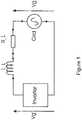
- Figure 1shows a typical setup of an inverter connected to the AC grid mains.
- the line connecting an inverter to the gridhas both inductance L_L and dc resistance R_L associated with it and whose combined effect form line impedance Z_L.
- the line impedanceis dependent on the length of the cable and the conductivity of the material. Due to the line impedance, the phase and magnitude of the grid voltage Vg differs from the phase and magnitude of the voltage Vg' that the inverter detects at its terminals. The difference between Vg and Vg' are dependent on the value of Z_L. For inverters connected to the grid and situated remotely such as on rooftop the impedance Z_L may be significant. The effect of this is that the inverter transfers current in phase with Vg' and not Vg.
- Figure 2shows the phasor diagram of the relationship between Vg and Vg', the inverter internal voltage V_i used to control current injection and the inverter output current Ig'.
- L_i and R_irepresent the inverter internal impedance though which power is transferred onto the grid.
- Vg ′Vg ⁇ Ig ′ jw L _ L + R _ L
- the angle Arepresents the difference in phase between Vg and Vg'.
- the result of this phase differenceis the transfer of reactive power between inverter and the grid. Reactive power is not converted into useful power but lost through parasitic resistance on the network. As a consequence the system efficiency is reduced.
- FIG. 3illustrates a system with multiple inverters.
- Vg 3 ′Vg ⁇ Ig 1 ′ + Ig 2 ′ + Ig 3 ′ Z _ L ⁇ Ig 3 ′ Z _ 3
- Vg 2 ′Vg ⁇ Ig 1 ′ + Ig 2 ′ + Ig 3 ′ Z _ L ⁇ Ig 1 ′ + Ig 2 ′ Z _ 4 ⁇ Ig 2 ′ Z _ 2
- Vg 1 ′Vg ⁇ Ig 1 ′ + Ig 2 ′ + Ig 3 ′ Z _ L ⁇ Ig 1 ′ + Ig 2 ′ Z _ 4 ⁇ Ig 1 ′ Z _ 1
- Vg 1 ′Vg ⁇ Ig 1 ′ + Ig 2 ′ + Ig 3 ′ Z _ L ⁇ Ig 1 ′ + Ig 2 ′ Z _ 4 ⁇ Ig 1 ′ Z _ 1
- the three inverters in figure 3all experience different values of grid voltage, Vg1', Vg2' and Vg3', due to the impedance in the line.
- the currents Ig1', Ig2' and Ig3'are generated by inverters 1, 2 and 3 respectively.
- the currentsare assumed to be in phase with the corresponding inverter voltages.
- Equations 2, 3 and 4show the relationships between each of the inverter voltages and the grid voltage.
- Figure 4shows the proposed solution to the problem of reactive power transfer.
- a grid sensorlocated at, or substantially near to the point at which power from the converter is injected onto the AC grid mains, is used to detect a number of characteristics of the AC grid mains, for example the current and/or grid voltage phases and frequency. This information is then communicated to the inverter, which is then used to control the current phase of the inverter such that the output current of the inverter is substantially synchronised to (ie in phase with) the voltage Vg.
- the communication of the sensed characteristics of the AC grid mainsnamely the phase of the current and/or voltage, enables the inverter to be controlled in order that its AC output is synchronised with that of the AC grid mains.
- the object of controlis the line current Ig flowing into the grid. The current is detected at the terminals of the grid supply and is therefore corrected from the effects of impedance on the system.
- Figure 5shows the resulting desirable phasor relationship between the grid voltage and the inverter current for a single inverter network.
- the communication systemcan be implemented either with the employment of a wireless network or a wired network.
- a wireless networklow rate data may be sent down the power lines throughout the house ring main.
- a radio protocolsuch as ZigBee, may be employed to communicate the data between the sensor and the inverter.
- the grid sensoris located at, or substantially near the point at which power from the output of the inverter is injected into the AC grid mains, for example at the house's switchboard.
- the sensormay be integrated into the switchboard in order to acquire phase and magnitude information of the grid current and voltage.
- FIG. 6shows a system of multiple inverters connected to the grid, and using the system of the present invention.
- the AC outputs of each of the inverters in the systemcan be synchronised to Vg regardless of the line impedance.
- each of the invertershas a receiver (here shown as a wireless receiver; the skilled reader would understand that a wired connection could be used instead) for receiving data from a single grid sensor located at, or substantially near to the point at which power generated from the inverters is injected into the AC grid mains.
- Each of the invertersis controlled in response to the data provided by the single grid sensor.
- Additional datais also captured at the inverter, in one embodiment such as the output voltage and/or current, the DC or AC power input, the AC output, the efficiency of the inverter and other such data.
- the systemtransmits such data from the inverter over the wired or wireless link back to the grid sensor.
- datawould, for example, enable the grid sensor to detect if one or more of the inverters was malfunctioning, and to alert a user that action is required to correct such a fault.
- the grid sensor arrangementcould also collate data collected from the gird and/or the inverters and display such data to a user on a display.
- a display of datawould enable a user to visualise that power being provided by the converter(s), the efficiency of the converts and/or how much power is being sent back to the grid at any time.
Landscapes
- Engineering & Computer Science (AREA)
- Power Engineering (AREA)
- Inverter Devices (AREA)
- Power Conversion In General (AREA)
Description
- The invention relates to power generation, and in particular to a grid synchroniser for connecting an AC output of a power converter to the AC grid mains.
- Attempts have been made previously to directly couple switching semiconductor devices to the grid in order to maintain phase synchronisation and simplify system design. One of the key problems is how to rapidly remove gate charge and at the same time minimise power loss in the driving circuit. If charge is not removed rapidly from the gate terminal a shoot-through problem results and a ground fault develops on the grid. One possible solution is to use small ohmic resistors. However, the use of small ohmic resistors to form potential dividing circuit often results in huge losses in the resistors and therefore reduced lifetime and reliability for the system.
- Also, many micropower generation systems, such as those in the home, typically comprise one or more of a number of solar cells (eg on the roof), wind turbines, combined heat and power systems and other like systems. The micropower generators generate electricity for the home, and the power is converted into useable voltage and current suitable for the home, for example 240V at 50Hz or 110V at 60Hz. However, more power than is actually required by the home is sometimes generated. If the micropower generation system were connected to the AC grid, from which power is normally drawn in conventional homes, this surplus power could be sent back to the AC grid.
- However, there exists a need for a system of synchronising the power generated by the converters to the power on the grid. Inverters are often used to generate an AC output from a DC input. The inverters are generally located within the proximity of the power source (solar cells, wind turbine etc). The point at which the inverter is connected to the AC grid mains is often remote from its physical location.
- Inverters connected to the grid remotely may experience a phase shifted line voltage due to line impedance and therefore transfer an increased amount of reactive power in the network. The increase in reactive power implies minimised system efficiency.
- There is therefore a need to enable the synchronisation of inverters to the same line voltage regardless of the line impedance between power switchboard and the point of connection of the inverter.
- We describe techniques to address the above problems. Background prior art can be found in
US2005/0179420 , which shows a single inverter being controlled so that the phase of its output current is kept in the phase of the grid voltage, further prior art can be found inUS2005/135031 ,DE32 36 071A ,US2367925 , andUS6311137 . - According to a first aspect of the present invention there is provided a system comprising a plurality of inverters each having a grid synchroniser, according to
independent claim 1. - According to a second aspect of the present invention there is provided a method of synchronising an AC output of a plurality of inverters to an AC grid mains, according to independent claim 7.
- Preferred embodiments are defined in the dependent claims.
- The communication of the sensed grid characteristics of the AC grid mains (for example the phase of the current and/or voltage), enables the inverter to be controlled in order that its AC output is synchronised with that of the AC grid mains, irrespective of the line load between the inverter and the grid connection.
- In embodiments, said receiver is in wired communication with a grid sensor. Preferably, said wired communication is through a power supply line. In alternative embodiments, said receiver is in wireless communication with a grid sensor.
- In embodiments, the sensed inverter characteristic comprises one or more of a phase of said AC output of said inverter, a power output or a power efficiency of said inverter.
- Sensing and transmitting the sensed grid characteristics of the AC grid mains (for example the phase of the current and/or voltage), enables the inverter to be controlled in order that its AC output is synchronised with that of the AC grid mains, irrespective of the line load between the inverter and the grid connection.
- These and other aspects of the invention will now be further dcseribed, by way of example only, with reference to the accompanying figures in which:
Figure 1 shows a typical setup of an inverter connected to the AC grid mains;Figure 2 shows the phasor diagram of the relationship between Vg and Vg';Figure 3 illustrates a system with multiple inverters;Figure 4 shows the system according to the present invention;Figure 5 shows the resulting desirable phasor relationship between the grid voltage and the inverter current for a single inverter network; andFigure 6 shows a system of multiple inverters connected to the grid according to the present invention.Figure 1 shows a typical setup of an inverter connected to the AC grid mains. The line connecting an inverter to the grid has both inductance L_L and dc resistance R_L associated with it and whose combined effect form line impedance Z_L. The line impedance is dependent on the length of the cable and the conductivity of the material. Due to the line impedance, the phase and magnitude of the grid voltage Vg differs from the phase and magnitude of the voltage Vg' that the inverter detects at its terminals. The difference between Vg and Vg' are dependent on the value of Z_L. For inverters connected to the grid and situated remotely such as on rooftop the impedance Z_L may be significant. The effect of this is that the inverter transfers current in phase with Vg' and not Vg.Figure 2 shows the phasor diagram of the relationship between Vg and Vg', the inverter internal voltage V_i used to control current injection and the inverter output current Ig'. L_i and R_i represent the inverter internal impedance though which power is transferred onto the grid.
- The angle A represents the difference in phase between Vg and Vg'. The result of this phase difference is the transfer of reactive power between inverter and the grid. Reactive power is not converted into useful power but lost through parasitic resistance on the network. As a consequence the system efficiency is reduced.
- This effect of line impedance may be severe in systems with multiple inverters connected to the grid remotely. Each of the inverter may experience different values of line impedance and therefore different values of Vg'.
Figure 3 illustrates a system with multiple inverters.


- The three inverters in
figure 3 all experience different values of grid voltage, Vg1', Vg2' and Vg3', due to the impedance in the line. The currents Ig1', Ig2' and Ig3' are generated byinverters Equations Figure 4 shows the proposed solution to the problem of reactive power transfer. A grid sensor, located at, or substantially near to the point at which power from the converter is injected onto the AC grid mains, is used to detect a number of characteristics of the AC grid mains, for example the current and/or grid voltage phases and frequency. This information is then communicated to the inverter, which is then used to control the current phase of the inverter such that the output current of the inverter is substantially synchronised to (ie in phase with) the voltage Vg.- Therefore, the communication of the sensed characteristics of the AC grid mains, namely the phase of the current and/or voltage, enables the inverter to be controlled in order that its AC output is synchronised with that of the AC grid mains. The object of control is the line current Ig flowing into the grid. The current is detected at the terminals of the grid supply and is therefore corrected from the effects of impedance on the system.
Figure 5 shows the resulting desirable phasor relationship between the grid voltage and the inverter current for a single inverter network.- The communication system can be implemented either with the employment of a wireless network or a wired network. For example, in a wired network, low rate data may be sent down the power lines throughout the house ring main. In a wireless network, a radio protocol such as ZigBee, may be employed to communicate the data between the sensor and the inverter.
- Many grid connected inverters come with some sort of communication capability already build in for data acquisition and fault diagnostic. It would be possible to build a synchronisation capability over the existing protocol in order to minimise costs. Alternatively, new protocols may be developed to communicate such data.
- The grid sensor is located at, or substantially near the point at which power from the output of the inverter is injected into the AC grid mains, for example at the house's switchboard.
- The sensor may be integrated into the switchboard in order to acquire phase and magnitude information of the grid current and voltage.
Figure 6 shows a system of multiple inverters connected to the grid, and using the system of the present invention. The AC outputs of each of the inverters in the system can be synchronised to Vg regardless of the line impedance. As can be seen, each of the inverters has a receiver (here shown as a wireless receiver; the skilled reader would understand that a wired connection could be used instead) for receiving data from a single grid sensor located at, or substantially near to the point at which power generated from the inverters is injected into the AC grid mains. Each of the inverters is controlled in response to the data provided by the single grid sensor.- Additional data is also captured at the inverter, in one embodiment such as the output voltage and/or current, the DC or AC power input, the AC output, the efficiency of the inverter and other such data.
- The system transmits such data from the inverter over the wired or wireless link back to the grid sensor. Such data would, for example, enable the grid sensor to detect if one or more of the inverters was malfunctioning, and to alert a user that action is required to correct such a fault.
- In embodiments, the grid sensor arrangement could also collate data collected from the gird and/or the inverters and display such data to a user on a display. Such a display of data would enable a user to visualise that power being provided by the converter(s), the efficiency of the converts and/or how much power is being sent back to the grid at any time.
- No doubt many other effective alternatives will occur to the skilled person. It will be understood that the invention is not limited to the described embodiments and encompasses modifications apparent to those skilled in the art lying within the scope of the claims appended hereto.


Claims (8)
- A system for power generation, the system comprising:a plurality of inverters each having a grid synchroniser, each said grid synchroniser to synchronise an AC output of a respective said inverter to an AC grid mains, each said inverter having a power input, a cable and an AC output for connection to said AC grid mains by said cable to provide a power supply input into said AC grid mains, wherein the cables of respective said inverters have different line impedances; the system further comprising:a grid sensor for said plurality of inverters, wherein the grid sensor is situated remotely from the physical locations of said inverters at a grid sensor location where AC current from each said AC output of said inverters is injected into said AC grid mains,an inverter sensor which is configured to sense an inverter characteristic of a said AC output of a said inverter and configured to transmit inverter data relating to said sensed inverter characteristic to said grid sensor andwherein each said grid synchroniser comprises:an inverter controller configured to control said AC output of said inverter, said controller including a data communications network receiver to receive grid data from said grid sensor via the data communications network, and wherein due to a said line impedance of said cable a voltage of said AC grid mains at said remote grid sensor location is phase shifted relative to a line voltage on said cable at said AC output, said grid sensor sensing a grid characteristic of said AC grid mains, wherein said sensed grid characteristic comprises a phase of said voltage of said AC grid mains at said grid sensor location and said received grid data indicates said phase,wherein said grid data comprises data relating to the grid characteristic of said AC grid mains sensed by said grid sensor, andwherein each said inverter controller is configured to control AC current output from a said AC output responsive to said grid data to synchronise phase of said AC current to said indicated phase, such that the phases of said AC currents from said AC outputs of said plurality of inverters are synchronised to said indicated phase irrespective of said different line impedances.
- A system according to claim 1, wherein said receiver is in wired communication with said grid sensor.
- A system according to claim 2, wherein said wired communication is through a power supply line.
- A system according to claim 1, wherein said receiver is in wireless communication with said grid sensor.
- A system according to claim 1, said plurality of said inverters each configured to input power into said AC grid mains at the same point.
- A system according to any preceding claim, wherein said sensed inverter characteristic comprises one or more of a phase of said AC output of said inverter, a power output or a power efficiency of said inverter.
- A method of synchronising an AC output of a plurality of inverters to an AC grid mains by using a grid synchronizer included in each of the inverters, said grid synhronizer comprising an inverter controller, each said inverter having a power input and an AC output connected by a cable to said AC grid mains to provide a power supply input into said AC grid mains, wherein the cables of respective said inverters have different line impedances, the method comprising:sensing a characteristic of said AC grid mains using a grid sensor located remotely from the physical location of said inverters, said grid sensor being situated at a location remote from each said inverter such that due to a said line impedance of a said cable a voltage of said AC grid mains at said remote grid sensor location is phase shifted relative to a line voltage on said cable at said AC output, wherein said sensed grid characteristic comprises a phase of said voltage of said AC grid mains at said remote grid sensor location and said sensing is performed at said remote grid sensor location by said grid sensor coupled to said AC grid mains at a point where AC current from each said AC output of said inverters is injected into said AC grid mains;transmitting grid data relating to said sensed grid characteristic via a data communications network to a data communications network receiver of each said inverter, wherein said transmitted grid data indicates said phase of said AC grid mains voltage;controlling, by said inverter controller, said AC current of each said AC output of said inverters responsive to said grid data relating to said sensed grid characteristic to synchronise phase of each said AC current to said indicated phase of said AC grid mains voltage, such that the phases of said AC currents from said AC outputs of said inverters are synchronised to said indicated phase of said AC grid mains voltage irrespective of said different line impedances;sensing a characteristic of a said AC output of a said inverter; andtransmitting inverter data relating to said sensed inverter characteristic to said grid sensor.
- A method according to claim 7, wherein said sensed inverter characteristic comprises one or more of a phase of said AC output of said inverter, a power output or a power efficiency of said inverter.
Applications Claiming Priority (3)
| Application Number | Priority Date | Filing Date | Title |
|---|---|---|---|
| GB0724828AGB2455755B (en) | 2007-12-20 | 2007-12-20 | Grid synchronisation |
| GB0724825AGB2455754B (en) | 2007-12-20 | 2007-12-20 | Driver circuits and techniques |
| PCT/GB2008/051216WO2009081205A2 (en) | 2007-12-20 | 2008-12-19 | Grid synchronisation |
Publications (2)
| Publication Number | Publication Date |
|---|---|
| EP2235807A2 EP2235807A2 (en) | 2010-10-06 |
| EP2235807B1true EP2235807B1 (en) | 2019-05-08 |
Family
ID=40560294
Family Applications (1)
| Application Number | Title | Priority Date | Filing Date |
|---|---|---|---|
| EP08865007.2AActiveEP2235807B1 (en) | 2007-12-20 | 2008-12-19 | Grid synchronisation |
Country Status (3)
| Country | Link |
|---|---|
| US (4) | US8310101B2 (en) |
| EP (1) | EP2235807B1 (en) |
| WO (1) | WO2009081205A2 (en) |
Families Citing this family (82)
| Publication number | Priority date | Publication date | Assignee | Title |
|---|---|---|---|---|
| US10693415B2 (en) | 2007-12-05 | 2020-06-23 | Solaredge Technologies Ltd. | Testing of a photovoltaic panel |
| US11881814B2 (en) | 2005-12-05 | 2024-01-23 | Solaredge Technologies Ltd. | Testing of a photovoltaic panel |
| US8473250B2 (en) | 2006-12-06 | 2013-06-25 | Solaredge, Ltd. | Monitoring of distributed power harvesting systems using DC power sources |
| US8013472B2 (en) | 2006-12-06 | 2011-09-06 | Solaredge, Ltd. | Method for distributed power harvesting using DC power sources |
| US12316274B2 (en) | 2006-12-06 | 2025-05-27 | Solaredge Technologies Ltd. | Pairing of components in a direct current distributed power generation system |
| US8618692B2 (en) | 2007-12-04 | 2013-12-31 | Solaredge Technologies Ltd. | Distributed power system using direct current power sources |
| US11296650B2 (en) | 2006-12-06 | 2022-04-05 | Solaredge Technologies Ltd. | System and method for protection during inverter shutdown in distributed power installations |
| US8384243B2 (en) | 2007-12-04 | 2013-02-26 | Solaredge Technologies Ltd. | Distributed power harvesting systems using DC power sources |
| US11888387B2 (en) | 2006-12-06 | 2024-01-30 | Solaredge Technologies Ltd. | Safety mechanisms, wake up and shutdown methods in distributed power installations |
| US11309832B2 (en) | 2006-12-06 | 2022-04-19 | Solaredge Technologies Ltd. | Distributed power harvesting systems using DC power sources |
| US11569659B2 (en) | 2006-12-06 | 2023-01-31 | Solaredge Technologies Ltd. | Distributed power harvesting systems using DC power sources |
| US8816535B2 (en) | 2007-10-10 | 2014-08-26 | Solaredge Technologies, Ltd. | System and method for protection during inverter shutdown in distributed power installations |
| US9130401B2 (en) | 2006-12-06 | 2015-09-08 | Solaredge Technologies Ltd. | Distributed power harvesting systems using DC power sources |
| US11735910B2 (en) | 2006-12-06 | 2023-08-22 | Solaredge Technologies Ltd. | Distributed power system using direct current power sources |
| US9088178B2 (en) | 2006-12-06 | 2015-07-21 | Solaredge Technologies Ltd | Distributed power harvesting systems using DC power sources |
| US11687112B2 (en) | 2006-12-06 | 2023-06-27 | Solaredge Technologies Ltd. | Distributed power harvesting systems using DC power sources |
| US8319483B2 (en) | 2007-08-06 | 2012-11-27 | Solaredge Technologies Ltd. | Digital average input current control in power converter |
| US11855231B2 (en) | 2006-12-06 | 2023-12-26 | Solaredge Technologies Ltd. | Distributed power harvesting systems using DC power sources |
| US8963369B2 (en) | 2007-12-04 | 2015-02-24 | Solaredge Technologies Ltd. | Distributed power harvesting systems using DC power sources |
| US8319471B2 (en) | 2006-12-06 | 2012-11-27 | Solaredge, Ltd. | Battery power delivery module |
| US9112379B2 (en) | 2006-12-06 | 2015-08-18 | Solaredge Technologies Ltd. | Pairing of components in a direct current distributed power generation system |
| US8947194B2 (en) | 2009-05-26 | 2015-02-03 | Solaredge Technologies Ltd. | Theft detection and prevention in a power generation system |
| US7994657B2 (en) | 2006-12-22 | 2011-08-09 | Solarbridge Technologies, Inc. | Modular system for unattended energy generation and storage |
| US7755916B2 (en) | 2007-10-11 | 2010-07-13 | Solarbridge Technologies, Inc. | Methods for minimizing double-frequency ripple power in single-phase power conditioners |
| WO2009073867A1 (en) | 2007-12-05 | 2009-06-11 | Solaredge, Ltd. | Parallel connected inverters |
| US9291696B2 (en) | 2007-12-05 | 2016-03-22 | Solaredge Technologies Ltd. | Photovoltaic system power tracking method |
| US11264947B2 (en) | 2007-12-05 | 2022-03-01 | Solaredge Technologies Ltd. | Testing of a photovoltaic panel |
| CN105244905B (en) | 2007-12-05 | 2019-05-21 | 太阳能安吉有限公司 | Release mechanism in distributed power device is waken up and method for closing |
| WO2009072076A2 (en) | 2007-12-05 | 2009-06-11 | Solaredge Technologies Ltd. | Current sensing on a mosfet |
| EP2235807B1 (en) | 2007-12-20 | 2019-05-08 | SolarCity Corporation | Grid synchronisation |
| US8111052B2 (en) | 2008-03-24 | 2012-02-07 | Solaredge Technologies Ltd. | Zero voltage switching |
| EP2294669B8 (en) | 2008-05-05 | 2016-12-07 | Solaredge Technologies Ltd. | Direct current power combiner |
| US20100213768A1 (en)* | 2009-02-24 | 2010-08-26 | Alex Faveluke | Apparatus for photovoltaic power generation |
| CN101877486B (en)* | 2009-04-30 | 2013-04-10 | 比亚迪股份有限公司 | Battery energy storage power station used for balancing power network load |
| US8482947B2 (en) | 2009-07-31 | 2013-07-09 | Solarbridge Technologies, Inc. | Apparatus and method for controlling DC-AC power conversion |
| US8462518B2 (en)* | 2009-10-12 | 2013-06-11 | Solarbridge Technologies, Inc. | Power inverter docking system for photovoltaic modules |
| US12418177B2 (en) | 2009-10-24 | 2025-09-16 | Solaredge Technologies Ltd. | Distributed power system using direct current power sources |
| US8824178B1 (en) | 2009-12-31 | 2014-09-02 | Solarbridge Technologies, Inc. | Parallel power converter topology |
| US8279649B2 (en) | 2010-10-11 | 2012-10-02 | Solarbridge Technologies, Inc. | Apparatus and method for controlling a power inverter |
| US9160408B2 (en) | 2010-10-11 | 2015-10-13 | Sunpower Corporation | System and method for establishing communication with an array of inverters |
| US8503200B2 (en) | 2010-10-11 | 2013-08-06 | Solarbridge Technologies, Inc. | Quadrature-corrected feedforward control apparatus and method for DC-AC power conversion |
| US10673222B2 (en) | 2010-11-09 | 2020-06-02 | Solaredge Technologies Ltd. | Arc detection and prevention in a power generation system |
| US10230310B2 (en) | 2016-04-05 | 2019-03-12 | Solaredge Technologies Ltd | Safety switch for photovoltaic systems |
| US10673229B2 (en) | 2010-11-09 | 2020-06-02 | Solaredge Technologies Ltd. | Arc detection and prevention in a power generation system |
| GB2485527B (en) | 2010-11-09 | 2012-12-19 | Solaredge Technologies Ltd | Arc detection and prevention in a power generation system |
| US8842454B2 (en) | 2010-11-29 | 2014-09-23 | Solarbridge Technologies, Inc. | Inverter array with localized inverter control |
| US9467063B2 (en) | 2010-11-29 | 2016-10-11 | Sunpower Corporation | Technologies for interleaved control of an inverter array |
| GB2486408A (en) | 2010-12-09 | 2012-06-20 | Solaredge Technologies Ltd | Disconnection of a string carrying direct current |
| GB2483317B (en) | 2011-01-12 | 2012-08-22 | Solaredge Technologies Ltd | Serially connected inverters |
| US8611107B2 (en) | 2011-04-27 | 2013-12-17 | Solarbridge Technologies, Inc. | Method and system for controlling a multi-stage power inverter |
| US8193788B2 (en) | 2011-04-27 | 2012-06-05 | Solarbridge Technologies, Inc. | Method and device for controlling a configurable power supply to provide AC and/or DC power output |
| US9065354B2 (en) | 2011-04-27 | 2015-06-23 | Sunpower Corporation | Multi-stage power inverter for power bus communication |
| US8922185B2 (en) | 2011-07-11 | 2014-12-30 | Solarbridge Technologies, Inc. | Device and method for global maximum power point tracking |
| US8570005B2 (en) | 2011-09-12 | 2013-10-29 | Solaredge Technologies Ltd. | Direct current link circuit |
| US8284574B2 (en) | 2011-10-17 | 2012-10-09 | Solarbridge Technologies, Inc. | Method and apparatus for controlling an inverter using pulse mode control |
| US9263971B2 (en) | 2011-12-16 | 2016-02-16 | Empower Micro Systems Inc. | Distributed voltage source inverters |
| GB2498365A (en) | 2012-01-11 | 2013-07-17 | Solaredge Technologies Ltd | Photovoltaic module |
| GB2498790A (en) | 2012-01-30 | 2013-07-31 | Solaredge Technologies Ltd | Maximising power in a photovoltaic distributed power system |
| GB2498791A (en) | 2012-01-30 | 2013-07-31 | Solaredge Technologies Ltd | Photovoltaic panel circuitry |
| US9853565B2 (en) | 2012-01-30 | 2017-12-26 | Solaredge Technologies Ltd. | Maximized power in a photovoltaic distributed power system |
| GB2499991A (en) | 2012-03-05 | 2013-09-11 | Solaredge Technologies Ltd | DC link circuit for photovoltaic array |
| US10115841B2 (en) | 2012-06-04 | 2018-10-30 | Solaredge Technologies Ltd. | Integrated photovoltaic panel circuitry |
| US9276635B2 (en) | 2012-06-29 | 2016-03-01 | Sunpower Corporation | Device, system, and method for communicating with a power inverter using power line communications |
| JP6076692B2 (en)* | 2012-10-26 | 2017-02-08 | 株式会社東芝 | Inverter device and inverter system |
| US9941813B2 (en) | 2013-03-14 | 2018-04-10 | Solaredge Technologies Ltd. | High frequency multi-level inverter |
| US9548619B2 (en) | 2013-03-14 | 2017-01-17 | Solaredge Technologies Ltd. | Method and apparatus for storing and depleting energy |
| US9584044B2 (en) | 2013-03-15 | 2017-02-28 | Sunpower Corporation | Technologies for converter topologies |
| EP3506370B1 (en) | 2013-03-15 | 2023-12-20 | Solaredge Technologies Ltd. | Bypass mechanism |
| US9564835B2 (en) | 2013-03-15 | 2017-02-07 | Sunpower Corporation | Inverter communications using output signal |
| DE102013205427A1 (en)* | 2013-03-27 | 2014-10-16 | Siemens Aktiengesellschaft | Feed-in device for feeding electrical current into a power network and method for operating such a feed device |
| US9882507B2 (en) | 2013-04-16 | 2018-01-30 | Solarcity Corporation | Power factor adjustment in multi-phase power system |
| US9318974B2 (en) | 2014-03-26 | 2016-04-19 | Solaredge Technologies Ltd. | Multi-level inverter with flying capacitor topology |
| RU2565664C1 (en) | 2014-07-15 | 2015-10-20 | Самсунг Электроникс Ко., Лтд. | Control method for systems of wireless power transmission |
| US10447040B2 (en) | 2014-10-15 | 2019-10-15 | Cummins Power Generation Ip, Inc. | Programmable inverter for controllable grid response |
| AU2015364718B2 (en) | 2014-12-16 | 2019-11-28 | Marici Holdings The Netherlands B.V. | Energy panel arrangement power dissipation |
| WO2016123305A1 (en) | 2015-01-28 | 2016-08-04 | Abb Technology Ag | Energy panel arrangement shutdown |
| WO2016134356A1 (en) | 2015-02-22 | 2016-08-25 | Abb Technology Ag | Photovoltaic string reverse polarity detection |
| US10809678B2 (en)* | 2015-03-16 | 2020-10-20 | Board Of Regents, The University Of Texas System | System and method for distributed control of an electrical network |
| US12057807B2 (en) | 2016-04-05 | 2024-08-06 | Solaredge Technologies Ltd. | Chain of power devices |
| US11018623B2 (en) | 2016-04-05 | 2021-05-25 | Solaredge Technologies Ltd. | Safety switch for photovoltaic systems |
| US11177663B2 (en) | 2016-04-05 | 2021-11-16 | Solaredge Technologies Ltd. | Chain of power devices |
| US12382520B2 (en)* | 2022-11-11 | 2025-08-05 | Tigo Energy, Inc. | Solar panel transmitter pairing process |
Citations (2)
| Publication number | Priority date | Publication date | Assignee | Title |
|---|---|---|---|---|
| US20030080741A1 (en)* | 2001-10-26 | 2003-05-01 | Lerow Kevin E. | Anti-islanding techniques for distributed power generation |
| EP1837985A2 (en)* | 2006-03-23 | 2007-09-26 | PVI Solutions Inc. | Mehtod and apparatus for converting direct surrent to alternating current |
Family Cites Families (58)
| Publication number | Priority date | Publication date | Assignee | Title |
|---|---|---|---|---|
| US2367925A (en) | 1942-05-15 | 1945-01-23 | Westinghouse Electric & Mfg Co | Power line synchronizing and control system |
| US3723769A (en) | 1971-11-01 | 1973-03-27 | Int Rectifier Corp | Solid state relay circuit with optical isolation and zero-cross firing |
| US4104687A (en) | 1976-11-24 | 1978-08-01 | S&C Electric Company | Device for detecting unbalanced conditions in a polyphase equipment bank |
| DE2810534C2 (en)* | 1978-03-10 | 1983-10-20 | Siemens AG, 1000 Berlin und 8000 München | Ripple control system |
| DE3236071A1 (en) | 1982-07-09 | 1984-01-12 | Siemens AG, 1000 Berlin und 8000 München | Device for parallel supply into an AC or three-phase network |
| JPS6079417A (en) | 1983-10-06 | 1985-05-07 | Nishimu Denshi Kogyo Kk | Power converter for solar battery |
| US4564767A (en)* | 1983-11-07 | 1986-01-14 | Tii Industries, Inc. | Uninterruptible switching power supply system |
| US4564896A (en)* | 1984-06-29 | 1986-01-14 | Heart Interface Corporation | Inverter with improved operating efficiencies |
| US4772994A (en) | 1987-09-10 | 1988-09-20 | Nishimu Electronics Industries, Co., Ltd. | Power source using high-frequency phase control |
| US5040105A (en)* | 1989-12-20 | 1991-08-13 | Sundstrand Corporation | Stepped-waveform inverter with eight subinverters |
| JPH0834709B2 (en) | 1990-01-31 | 1996-03-29 | 株式会社日立製作所 | Semiconductor integrated circuit and electric motor control device using the same |
| US5083039B1 (en)* | 1991-02-01 | 1999-11-16 | Zond Energy Systems Inc | Variable speed wind turbine |
| DE4208894A1 (en) | 1992-03-19 | 1993-09-23 | Abb Patent Gmbh | CIRCUIT FOR CONTROLLING A VOLTAGE-CONTROLLED SEMICONDUCTOR SWITCH |
| US5504449A (en) | 1992-04-09 | 1996-04-02 | Harris Corporation | Power driver circuit |
| AU655889B2 (en) | 1992-06-24 | 1995-01-12 | Kabushiki Kaisha Toshiba | Inverter protection device |
| US5982645A (en) | 1992-08-25 | 1999-11-09 | Square D Company | Power conversion and distribution system |
| US5576941A (en) | 1994-08-10 | 1996-11-19 | York Technologies, Inc. | Modular power supply system |
| DE69620124T2 (en) | 1995-12-20 | 2002-10-31 | Sharp Kk | Inverter control method and device |
| US5734565A (en) | 1996-08-16 | 1998-03-31 | American Superconductor Corporation | Reducing switching losses in series connected bridge inverters and amplifiers |
| US6219623B1 (en)* | 1997-11-24 | 2001-04-17 | Plug Power, Inc. | Anti-islanding method and apparatus for distributed power generation |
| US5963078A (en)* | 1998-01-26 | 1999-10-05 | Peco Ii, Inc. | Transformer coupled FET drive circuit |
| US5930131A (en) | 1998-05-28 | 1999-07-27 | Long Well Electronics Corp. | Controlling device for conversion of DC power to sine wave AC power |
| US6429546B1 (en) | 1998-11-20 | 2002-08-06 | Georgia Tech Research Corporation | Systems and methods for preventing islanding of grid-connected electrical power systems |
| JP2000284006A (en) | 1999-01-27 | 2000-10-13 | Canon Inc | Information display device used for power generation system, solar power generation system, information relay device, information display method, information relay method, computer product, and information transmission method |
| US6404655B1 (en)* | 1999-12-07 | 2002-06-11 | Semikron, Inc. | Transformerless 3 phase power inverter |
| US6239997B1 (en) | 2000-09-01 | 2001-05-29 | Ford Motor Company | System for connecting and synchronizing a supplemental power source to a power grid |
| US6888263B2 (en) | 2001-05-23 | 2005-05-03 | Ebara Corporation | Gas turbine generator |
| EP1339153B1 (en) | 2002-02-19 | 2011-10-05 | Fraunhofer-Gesellschaft zur Förderung der angewandten Forschung e.V. | Device for connecting a building or similar to a low voltage electric network |
| JP2004312994A (en) | 2003-03-27 | 2004-11-04 | Tokyo Rika Daigaku Kagaku Gijutsu Koryu Center | Power conditioner for passive generator output system |
| US7095597B1 (en) | 2003-04-30 | 2006-08-22 | Clipper Windpower Technology, Inc. | Distributed static var compensation (DSVC) system for wind and water turbine applications |
| US7042110B2 (en)* | 2003-05-07 | 2006-05-09 | Clipper Windpower Technology, Inc. | Variable speed distributed drive train wind turbine system |
| US6940735B2 (en) | 2003-11-14 | 2005-09-06 | Ballard Power Systems Corporation | Power converter system |
| US7183667B2 (en) | 2003-12-19 | 2007-02-27 | Square D Company | Method and apparatus for power inverter synchronization |
| JP4585767B2 (en)* | 2004-01-14 | 2010-11-24 | 本田技研工業株式会社 | Fuel cell monitoring device |
| US7280377B2 (en)* | 2004-08-16 | 2007-10-09 | Caterpillar Inc. | Power converter in a utility interactive system |
| GB2415841B (en) | 2004-11-08 | 2006-05-10 | Enecsys Ltd | Power conditioning unit |
| US7193872B2 (en) | 2005-01-28 | 2007-03-20 | Kasemsan Siri | Solar array inverter with maximum power tracking |
| US20070081371A1 (en) | 2005-04-25 | 2007-04-12 | Wittenbreder Ernest H Jr | Synchronous Rectifier Control Circuits |
| US7479774B2 (en) | 2006-04-07 | 2009-01-20 | Yuan Ze University | High-performance solar photovoltaic (PV) energy conversion system |
| US8103389B2 (en)* | 2006-05-18 | 2012-01-24 | Gridpoint, Inc. | Modular energy control system |
| US7626834B2 (en) | 2006-06-29 | 2009-12-01 | Enecsys Limited | Double ended converter with output synchronous rectifier and auxiliary input regulator |
| US9130401B2 (en) | 2006-12-06 | 2015-09-08 | Solaredge Technologies Ltd. | Distributed power harvesting systems using DC power sources |
| US9088178B2 (en)* | 2006-12-06 | 2015-07-21 | Solaredge Technologies Ltd | Distributed power harvesting systems using DC power sources |
| GB2444528B (en) | 2006-12-09 | 2011-07-06 | Converteam Ltd | Methods for synchronising a plurality of generators |
| US10468993B2 (en) | 2007-05-17 | 2019-11-05 | Enphase Energy, Inc. | Inverter for use in photovoltaic module |
| US7660135B2 (en) | 2007-05-23 | 2010-02-09 | Hamilton Sundstrand Corporation | Universal AC high power inveter with galvanic isolation for linear and non-linear loads |
| US7787270B2 (en) | 2007-06-06 | 2010-08-31 | General Electric Company | DC-DC and DC-AC power conversion system |
| CA2693109A1 (en)* | 2007-07-16 | 2009-01-22 | Enphase Energy, Inc. | Method and apparatus for anti-islanding of distributed power generation systems |
| US7986539B2 (en)* | 2007-09-26 | 2011-07-26 | Enphase Energy, Inc. | Method and apparatus for maximum power point tracking in power conversion based on dual feedback loops and power ripples |
| GB2455755B (en) | 2007-12-20 | 2010-10-20 | Enecsys Ltd | Grid synchronisation |
| EP2235807B1 (en) | 2007-12-20 | 2019-05-08 | SolarCity Corporation | Grid synchronisation |
| GB2455754B (en) | 2007-12-20 | 2010-09-22 | Enecsys Ltd | Driver circuits and techniques |
| CN102007661A (en)* | 2008-02-21 | 2011-04-06 | 斯特拉瑞斯公司 | Photovoltaic ladder inverter |
| US7817450B2 (en)* | 2008-03-26 | 2010-10-19 | Enphase Energy, Inc. | Method and apparatus for resetting a silicon controlled rectifier bridge |
| US8139382B2 (en) | 2008-05-14 | 2012-03-20 | National Semiconductor Corporation | System and method for integrating local maximum power point tracking into an energy generating system having centralized maximum power point tracking |
| US8098055B2 (en)* | 2008-08-01 | 2012-01-17 | Tigo Energy, Inc. | Step-up converter systems and methods |
| US20100157632A1 (en) | 2008-12-20 | 2010-06-24 | Azuray Technologies, Inc. | Energy Conversion Systems With Power Control |
| US8922062B2 (en) | 2011-03-14 | 2014-12-30 | Sunpower Corporation | Automatic voltage regulation for photovoltaic systems |
- 2008
- 2008-12-19EPEP08865007.2Apatent/EP2235807B1/enactiveActive
- 2008-12-19USUS12/809,436patent/US8310101B2/enactiveActive
- 2008-12-19WOPCT/GB2008/051216patent/WO2009081205A2/enactiveApplication Filing
- 2012
- 2012-10-19USUS13/656,641patent/US9997923B2/enactiveActive
- 2018
- 2018-04-24USUS15/961,356patent/US10903658B2/enactiveActive
- 2021
- 2021-01-25USUS17/157,771patent/US11303134B2/enactiveActive
Patent Citations (2)
| Publication number | Priority date | Publication date | Assignee | Title |
|---|---|---|---|---|
| US20030080741A1 (en)* | 2001-10-26 | 2003-05-01 | Lerow Kevin E. | Anti-islanding techniques for distributed power generation |
| EP1837985A2 (en)* | 2006-03-23 | 2007-09-26 | PVI Solutions Inc. | Mehtod and apparatus for converting direct surrent to alternating current |
Also Published As
| Publication number | Publication date |
|---|---|
| US20130134790A1 (en) | 2013-05-30 |
| WO2009081205A3 (en) | 2009-10-08 |
| US20180241217A1 (en) | 2018-08-23 |
| WO2009081205A2 (en) | 2009-07-02 |
| US20110049990A1 (en) | 2011-03-03 |
| US9997923B2 (en) | 2018-06-12 |
| US8310101B2 (en) | 2012-11-13 |
| US10903658B2 (en) | 2021-01-26 |
| US11303134B2 (en) | 2022-04-12 |
| EP2235807A2 (en) | 2010-10-06 |
| US20210226453A1 (en) | 2021-07-22 |
Similar Documents
| Publication | Publication Date | Title |
|---|---|---|
| EP2235807B1 (en) | Grid synchronisation | |
| GB2455755A (en) | Grid synchronizer for inverter | |
| US8922048B2 (en) | PV sub-generator junction box, PV generator junction box, and PV inverter for a PV system, and PV system | |
| US10965153B2 (en) | Methods of microgrid communications and connection transitions | |
| US9263971B2 (en) | Distributed voltage source inverters | |
| KR101390641B1 (en) | System and method for converting electric power, and apparatus and method for controlling the system | |
| CN104953947B (en) | Monitoring system and communication method for photovoltaic power generation | |
| CN105164915A (en) | Measurement, control and harvest optimization device for solar modules requiring fewer connections | |
| US10193446B2 (en) | Multi-module DC-to-DC power transformation system | |
| CN105119378B (en) | Low-voltage distributing line on-line monitoring system | |
| US20220393721A1 (en) | Method and Apparatus to Enable Communication and Control in a Power System | |
| EP2765679A9 (en) | Intelligent electrical power network device | |
| JPWO2018105695A1 (en) | Power transmission system | |
| CN104242461A (en) | Intelligent sectionalizer | |
| US20240063754A1 (en) | Power Converter Box and Photovoltaic System | |
| CN104333039B (en) | Serial mini inverter system and operation method of inverters and grid connector thereof | |
| CN102437793A (en) | Distributed grid-connected solar energy photovoltaic system | |
| EP3493360A1 (en) | A method and a system for efficient distribution of electrical energy in a peer-to-peer distributed energy network | |
| CN111682646A (en) | Electronic equipment communication system and method | |
| CN103178603A (en) | A 10 kV distribution network load transfer control system and load transfer method | |
| CN109038785A (en) | Low pressure electricity getting system | |
| CN202616800U (en) | Distributed grid-connected solar-energy photovoltaic system | |
| EP3024119A1 (en) | Control device, panelboard and control method | |
| JP6434097B2 (en) | Control device, control system, distribution board and control method | |
| CN120457611A (en) | Power supply apparatus, power supply method, power supply system, and power supply network |
Legal Events
| Date | Code | Title | Description |
|---|---|---|---|
| PUAI | Public reference made under article 153(3) epc to a published international application that has entered the european phase | Free format text:ORIGINAL CODE: 0009012 | |
| 17P | Request for examination filed | Effective date:20100720 | |
| AK | Designated contracting states | Kind code of ref document:A2 Designated state(s):AT BE BG CH CY CZ DE DK EE ES FI FR GB GR HR HU IE IS IT LI LT LU LV MC MT NL NO PL PT RO SE SI SK TR | |
| AX | Request for extension of the european patent | Extension state:AL BA MK RS | |
| RIN1 | Information on inventor provided before grant (corrected) | Inventor name:VIRAJ, ANDRABADU Inventor name:CHISENGA, LESLEY Inventor name:AMARATUNGA, GEHAN, ANIL, JOSEPH | |
| DAX | Request for extension of the european patent (deleted) | ||
| RAP1 | Party data changed (applicant data changed or rights of an application transferred) | Owner name:SOLARCITY CORPORATION | |
| 17Q | First examination report despatched | Effective date:20160331 | |
| STAA | Information on the status of an ep patent application or granted ep patent | Free format text:STATUS: EXAMINATION IS IN PROGRESS | |
| REG | Reference to a national code | Ref country code:DE Ref legal event code:R079 Ref document number:602008060045 Country of ref document:DE Free format text:PREVIOUS MAIN CLASS: H02J0003400000 Ipc:H02J0003480000 | |
| GRAP | Despatch of communication of intention to grant a patent | Free format text:ORIGINAL CODE: EPIDOSNIGR1 | |
| STAA | Information on the status of an ep patent application or granted ep patent | Free format text:STATUS: GRANT OF PATENT IS INTENDED | |
| RIC1 | Information provided on ipc code assigned before grant | Ipc:H02J 3/48 20060101AFI20181123BHEP Ipc:H02J 3/38 20060101ALN20181123BHEP | |
| INTG | Intention to grant announced | Effective date:20181221 | |
| GRAS | Grant fee paid | Free format text:ORIGINAL CODE: EPIDOSNIGR3 | |
| GRAA | (expected) grant | Free format text:ORIGINAL CODE: 0009210 | |
| STAA | Information on the status of an ep patent application or granted ep patent | Free format text:STATUS: THE PATENT HAS BEEN GRANTED | |
| AK | Designated contracting states | Kind code of ref document:B1 Designated state(s):AT BE BG CH CY CZ DE DK EE ES FI FR GB GR HR HU IE IS IT LI LT LU LV MC MT NL NO PL PT RO SE SI SK TR | |
| REG | Reference to a national code | Ref country code:GB Ref legal event code:FG4D | |
| REG | Reference to a national code | Ref country code:CH Ref legal event code:EP Ref country code:AT Ref legal event code:REF Ref document number:1131720 Country of ref document:AT Kind code of ref document:T Effective date:20190515 | |
| REG | Reference to a national code | Ref country code:DE Ref legal event code:R096 Ref document number:602008060045 Country of ref document:DE Ref country code:IE Ref legal event code:FG4D | |
| REG | Reference to a national code | Ref country code:NL Ref legal event code:MP Effective date:20190508 | |
| REG | Reference to a national code | Ref country code:LT Ref legal event code:MG4D | |
| PG25 | Lapsed in a contracting state [announced via postgrant information from national office to epo] | Ref country code:FI Free format text:LAPSE BECAUSE OF FAILURE TO SUBMIT A TRANSLATION OF THE DESCRIPTION OR TO PAY THE FEE WITHIN THE PRESCRIBED TIME-LIMIT Effective date:20190508 Ref country code:LT Free format text:LAPSE BECAUSE OF FAILURE TO SUBMIT A TRANSLATION OF THE DESCRIPTION OR TO PAY THE FEE WITHIN THE PRESCRIBED TIME-LIMIT Effective date:20190508 Ref country code:NL Free format text:LAPSE BECAUSE OF FAILURE TO SUBMIT A TRANSLATION OF THE DESCRIPTION OR TO PAY THE FEE WITHIN THE PRESCRIBED TIME-LIMIT Effective date:20190508 Ref country code:ES Free format text:LAPSE BECAUSE OF FAILURE TO SUBMIT A TRANSLATION OF THE DESCRIPTION OR TO PAY THE FEE WITHIN THE PRESCRIBED TIME-LIMIT Effective date:20190508 Ref country code:HR Free format text:LAPSE BECAUSE OF FAILURE TO SUBMIT A TRANSLATION OF THE DESCRIPTION OR TO PAY THE FEE WITHIN THE PRESCRIBED TIME-LIMIT Effective date:20190508 Ref country code:PT Free format text:LAPSE BECAUSE OF FAILURE TO SUBMIT A TRANSLATION OF THE DESCRIPTION OR TO PAY THE FEE WITHIN THE PRESCRIBED TIME-LIMIT Effective date:20190908 Ref country code:SE Free format text:LAPSE BECAUSE OF FAILURE TO SUBMIT A TRANSLATION OF THE DESCRIPTION OR TO PAY THE FEE WITHIN THE PRESCRIBED TIME-LIMIT Effective date:20190508 Ref country code:NO Free format text:LAPSE BECAUSE OF FAILURE TO SUBMIT A TRANSLATION OF THE DESCRIPTION OR TO PAY THE FEE WITHIN THE PRESCRIBED TIME-LIMIT Effective date:20190808 | |
| PG25 | Lapsed in a contracting state [announced via postgrant information from national office to epo] | Ref country code:LV Free format text:LAPSE BECAUSE OF FAILURE TO SUBMIT A TRANSLATION OF THE DESCRIPTION OR TO PAY THE FEE WITHIN THE PRESCRIBED TIME-LIMIT Effective date:20190508 Ref country code:GR Free format text:LAPSE BECAUSE OF FAILURE TO SUBMIT A TRANSLATION OF THE DESCRIPTION OR TO PAY THE FEE WITHIN THE PRESCRIBED TIME-LIMIT Effective date:20190809 Ref country code:BG Free format text:LAPSE BECAUSE OF FAILURE TO SUBMIT A TRANSLATION OF THE DESCRIPTION OR TO PAY THE FEE WITHIN THE PRESCRIBED TIME-LIMIT Effective date:20190808 | |
| REG | Reference to a national code | Ref country code:AT Ref legal event code:MK05 Ref document number:1131720 Country of ref document:AT Kind code of ref document:T Effective date:20190508 | |
| REG | Reference to a national code | Ref country code:GB Ref legal event code:732E Free format text:REGISTERED BETWEEN 20191128 AND 20191204 | |
| RAP2 | Party data changed (patent owner data changed or rights of a patent transferred) | Owner name:TESLA, INC. | |
| PG25 | Lapsed in a contracting state [announced via postgrant information from national office to epo] | Ref country code:CZ Free format text:LAPSE BECAUSE OF FAILURE TO SUBMIT A TRANSLATION OF THE DESCRIPTION OR TO PAY THE FEE WITHIN THE PRESCRIBED TIME-LIMIT Effective date:20190508 Ref country code:RO Free format text:LAPSE BECAUSE OF FAILURE TO SUBMIT A TRANSLATION OF THE DESCRIPTION OR TO PAY THE FEE WITHIN THE PRESCRIBED TIME-LIMIT Effective date:20190508 Ref country code:SK Free format text:LAPSE BECAUSE OF FAILURE TO SUBMIT A TRANSLATION OF THE DESCRIPTION OR TO PAY THE FEE WITHIN THE PRESCRIBED TIME-LIMIT Effective date:20190508 Ref country code:AT Free format text:LAPSE BECAUSE OF FAILURE TO SUBMIT A TRANSLATION OF THE DESCRIPTION OR TO PAY THE FEE WITHIN THE PRESCRIBED TIME-LIMIT Effective date:20190508 Ref country code:DK Free format text:LAPSE BECAUSE OF FAILURE TO SUBMIT A TRANSLATION OF THE DESCRIPTION OR TO PAY THE FEE WITHIN THE PRESCRIBED TIME-LIMIT Effective date:20190508 Ref country code:EE Free format text:LAPSE BECAUSE OF FAILURE TO SUBMIT A TRANSLATION OF THE DESCRIPTION OR TO PAY THE FEE WITHIN THE PRESCRIBED TIME-LIMIT Effective date:20190508 | |
| REG | Reference to a national code | Ref country code:DE Ref legal event code:R097 Ref document number:602008060045 Country of ref document:DE | |
| PG25 | Lapsed in a contracting state [announced via postgrant information from national office to epo] | Ref country code:IT Free format text:LAPSE BECAUSE OF FAILURE TO SUBMIT A TRANSLATION OF THE DESCRIPTION OR TO PAY THE FEE WITHIN THE PRESCRIBED TIME-LIMIT Effective date:20190508 | |
| PLBE | No opposition filed within time limit | Free format text:ORIGINAL CODE: 0009261 | |
| STAA | Information on the status of an ep patent application or granted ep patent | Free format text:STATUS: NO OPPOSITION FILED WITHIN TIME LIMIT | |
| PG25 | Lapsed in a contracting state [announced via postgrant information from national office to epo] | Ref country code:TR Free format text:LAPSE BECAUSE OF FAILURE TO SUBMIT A TRANSLATION OF THE DESCRIPTION OR TO PAY THE FEE WITHIN THE PRESCRIBED TIME-LIMIT Effective date:20190508 | |
| 26N | No opposition filed | Effective date:20200211 | |
| PG25 | Lapsed in a contracting state [announced via postgrant information from national office to epo] | Ref country code:PL Free format text:LAPSE BECAUSE OF FAILURE TO SUBMIT A TRANSLATION OF THE DESCRIPTION OR TO PAY THE FEE WITHIN THE PRESCRIBED TIME-LIMIT Effective date:20190508 | |
| PG25 | Lapsed in a contracting state [announced via postgrant information from national office to epo] | Ref country code:SI Free format text:LAPSE BECAUSE OF FAILURE TO SUBMIT A TRANSLATION OF THE DESCRIPTION OR TO PAY THE FEE WITHIN THE PRESCRIBED TIME-LIMIT Effective date:20190508 | |
| REG | Reference to a national code | Ref country code:CH Ref legal event code:PL | |
| REG | Reference to a national code | Ref country code:BE Ref legal event code:MM Effective date:20191231 | |
| PG25 | Lapsed in a contracting state [announced via postgrant information from national office to epo] | Ref country code:MC Free format text:LAPSE BECAUSE OF FAILURE TO SUBMIT A TRANSLATION OF THE DESCRIPTION OR TO PAY THE FEE WITHIN THE PRESCRIBED TIME-LIMIT Effective date:20190508 | |
| PG25 | Lapsed in a contracting state [announced via postgrant information from national office to epo] | Ref country code:IE Free format text:LAPSE BECAUSE OF NON-PAYMENT OF DUE FEES Effective date:20191219 Ref country code:LU Free format text:LAPSE BECAUSE OF NON-PAYMENT OF DUE FEES Effective date:20191219 | |
| PG25 | Lapsed in a contracting state [announced via postgrant information from national office to epo] | Ref country code:LI Free format text:LAPSE BECAUSE OF NON-PAYMENT OF DUE FEES Effective date:20191231 Ref country code:CH Free format text:LAPSE BECAUSE OF NON-PAYMENT OF DUE FEES Effective date:20191231 Ref country code:BE Free format text:LAPSE BECAUSE OF NON-PAYMENT OF DUE FEES Effective date:20191231 | |
| PG25 | Lapsed in a contracting state [announced via postgrant information from national office to epo] | Ref country code:CY Free format text:LAPSE BECAUSE OF FAILURE TO SUBMIT A TRANSLATION OF THE DESCRIPTION OR TO PAY THE FEE WITHIN THE PRESCRIBED TIME-LIMIT Effective date:20190508 | |
| PG25 | Lapsed in a contracting state [announced via postgrant information from national office to epo] | Ref country code:IS Free format text:LAPSE BECAUSE OF FAILURE TO SUBMIT A TRANSLATION OF THE DESCRIPTION OR TO PAY THE FEE WITHIN THE PRESCRIBED TIME-LIMIT Effective date:20190908 | |
| PG25 | Lapsed in a contracting state [announced via postgrant information from national office to epo] | Ref country code:HU Free format text:LAPSE BECAUSE OF FAILURE TO SUBMIT A TRANSLATION OF THE DESCRIPTION OR TO PAY THE FEE WITHIN THE PRESCRIBED TIME-LIMIT; INVALID AB INITIO Effective date:20081219 Ref country code:MT Free format text:LAPSE BECAUSE OF FAILURE TO SUBMIT A TRANSLATION OF THE DESCRIPTION OR TO PAY THE FEE WITHIN THE PRESCRIBED TIME-LIMIT Effective date:20190508 | |
| P01 | Opt-out of the competence of the unified patent court (upc) registered | Effective date:20230512 | |
| PGFP | Annual fee paid to national office [announced via postgrant information from national office to epo] | Ref country code:GB Payment date:20241217 Year of fee payment:17 | |
| PGFP | Annual fee paid to national office [announced via postgrant information from national office to epo] | Ref country code:FR Payment date:20241227 Year of fee payment:17 | |
| PGFP | Annual fee paid to national office [announced via postgrant information from national office to epo] | Ref country code:DE Payment date:20241227 Year of fee payment:17 |