EP2235578B2 - System, device, and method for laser capture microdissection - Google Patents
System, device, and method for laser capture microdissectionDownload PDFInfo
- Publication number
- EP2235578B2 EP2235578B2EP08867252.2AEP08867252AEP2235578B2EP 2235578 B2EP2235578 B2EP 2235578B2EP 08867252 AEP08867252 AEP 08867252AEP 2235578 B2EP2235578 B2EP 2235578B2
- Authority
- EP
- European Patent Office
- Prior art keywords
- coordinates
- unit
- interest
- digital image
- slide
- Prior art date
- Legal status (The legal status is an assumption and is not a legal conclusion. Google has not performed a legal analysis and makes no representation as to the accuracy of the status listed.)
- Active
Links
- 238000000034methodMethods0.000titleclaimsdescription31
- 238000000370laser capture micro-dissectionMethods0.000titleclaimsdescription18
- 238000003384imaging methodMethods0.000claimsdescription27
- 238000012800visualizationMethods0.000claimsdescription15
- 239000012472biological sampleSubstances0.000claimsdescription13
- 230000001131transforming effectEffects0.000claimsdescription4
- 238000003018immunoassayMethods0.000claimsdescription2
- 238000002493microarrayMethods0.000claimsdescription2
- 238000003752polymerase chain reactionMethods0.000claimsdescription2
- 239000011521glassSubstances0.000description11
- 210000001519tissueAnatomy0.000description8
- 230000008569processEffects0.000description7
- 238000012546transferMethods0.000description6
- 230000009466transformationEffects0.000description6
- 239000011159matrix materialSubstances0.000description5
- 238000010586diagramMethods0.000description4
- 238000010191image analysisMethods0.000description4
- 238000012545processingMethods0.000description4
- 239000000523sampleSubstances0.000description4
- 238000004458analytical methodMethods0.000description3
- 230000003287optical effectEffects0.000description3
- 238000013519translationMethods0.000description3
- 238000004891communicationMethods0.000description2
- 238000001531micro-dissectionMethods0.000description2
- 230000003213activating effectEffects0.000description1
- 238000003556assayMethods0.000description1
- 239000008280bloodSubstances0.000description1
- 210000004369bloodAnatomy0.000description1
- 238000004113cell cultureMethods0.000description1
- 230000008859changeEffects0.000description1
- 239000000470constituentSubstances0.000description1
- 230000007812deficiencyEffects0.000description1
- 230000001419dependent effectEffects0.000description1
- 238000006073displacement reactionMethods0.000description1
- 239000000975dyeSubstances0.000description1
- 238000005516engineering processMethods0.000description1
- 210000000981epitheliumAnatomy0.000description1
- 230000036541healthEffects0.000description1
- 238000005286illuminationMethods0.000description1
- 238000002955isolationMethods0.000description1
- 238000013507mappingMethods0.000description1
- 230000007246mechanismEffects0.000description1
- 239000012188paraffin waxSubstances0.000description1
- 238000002360preparation methodMethods0.000description1
- 102000004169proteins and genesHuman genes0.000description1
- 108090000623proteins and genesProteins0.000description1
- 238000011160researchMethods0.000description1
- 238000004513sizingMethods0.000description1
- 239000007787solidSubstances0.000description1
Images


Classifications
- G—PHYSICS
- G01—MEASURING; TESTING
- G01N—INVESTIGATING OR ANALYSING MATERIALS BY DETERMINING THEIR CHEMICAL OR PHYSICAL PROPERTIES
- G01N1/00—Sampling; Preparing specimens for investigation
- G01N1/28—Preparing specimens for investigation including physical details of (bio-)chemical methods covered elsewhere, e.g. G01N33/50, C12Q
- G01N1/2813—Producing thin layers of samples on a substrate, e.g. smearing, spinning-on
- G—PHYSICS
- G02—OPTICS
- G02B—OPTICAL ELEMENTS, SYSTEMS OR APPARATUS
- G02B21/00—Microscopes
- G02B21/32—Micromanipulators structurally combined with microscopes
- G—PHYSICS
- G02—OPTICS
- G02B—OPTICAL ELEMENTS, SYSTEMS OR APPARATUS
- G02B21/00—Microscopes
- G02B21/36—Microscopes arranged for photographic purposes or projection purposes or digital imaging or video purposes including associated control and data processing arrangements
- G02B21/365—Control or image processing arrangements for digital or video microscopes
- G—PHYSICS
- G01—MEASURING; TESTING
- G01N—INVESTIGATING OR ANALYSING MATERIALS BY DETERMINING THEIR CHEMICAL OR PHYSICAL PROPERTIES
- G01N1/00—Sampling; Preparing specimens for investigation
- G01N1/28—Preparing specimens for investigation including physical details of (bio-)chemical methods covered elsewhere, e.g. G01N33/50, C12Q
- G01N1/2813—Producing thin layers of samples on a substrate, e.g. smearing, spinning-on
- G01N2001/2833—Collecting samples on a sticky, tacky, adhesive surface
- G01N2001/284—Collecting samples on a sticky, tacky, adhesive surface using local activation of adhesive, i.e. Laser Capture Microdissection
- G—PHYSICS
- G01—MEASURING; TESTING
- G01N—INVESTIGATING OR ANALYSING MATERIALS BY DETERMINING THEIR CHEMICAL OR PHYSICAL PROPERTIES
- G01N1/00—Sampling; Preparing specimens for investigation
- G01N1/28—Preparing specimens for investigation including physical details of (bio-)chemical methods covered elsewhere, e.g. G01N33/50, C12Q
- G01N1/286—Preparing specimens for investigation including physical details of (bio-)chemical methods covered elsewhere, e.g. G01N33/50, C12Q involving mechanical work, e.g. chopping, disintegrating, compacting, homogenising
- G01N2001/2873—Cutting or cleaving
- G01N2001/2886—Laser cutting, e.g. tissue catapult
Definitions
- the inventionrelates generally to microdissection. More particularly, the invention relates to a system and method for designating and capturing targets of interest for microdissection according to the preamble of claim 1 or 3.
- LCMDLaser Capture Microdissection
- One method of performing LCMDis to apply a transfer film to the surface of a tissue section. Under a microscope, the thin tissue section is viewed through a glass slide on which it is mounted and individual cells or clusters of cells are identified for isolation. When the isolated cells are in the field of view, the microscope operator actives a near IR laser diode integral with the microscope optics. The pulsed laser beam activates a precise spot on the transfer film, fusing the film with the underlying isolated cells. The transfer film with the bonded cells is then lifted off the thin tissue section, leaving the other, non-isolated cells on the glass slide.
- LCMDcan be performed on a variety of tissue samples including blood smears, cytologic preparations, cell cultures, aliquots of solid tissues, and frozen and paraffin embedded archival tissues. These individual cells can then be analyzed using a variety of techniques to analyze their various constituents by such techniques as Polymerase Chain Reaction ("PCR"), immunoassays, microarrays, or the like. This has proven valuable in research by enabling very precise molecular assays to be performed without compromising the ability to target particular cells. Further, because LCMD does not alter or damage the morphology and chemistry of the sample collected, nor the surrounding cells, LCMD is a useful method of collecting selected cells for DNA, RNA, and protein analyses.
- PCRPolymerase Chain Reaction
- a LCMD system according to the preamble of claim 1is known from US 2007/0066967 A1 or WO 2004/025569 A2 .
- Embodiments of the present inventionresolve many of the above-described deficiencies and drawbacks, and are directed to a system and method for obtaining samples from a laser capture microdissection system.
- a slidesuch as a glass slide, containing a tissue or the like sample can be scanned to create a digital slide.
- the digital slidecan then be annotated by a user, such as an expert in cell identification.
- the coordinates of the annotationscan then be subject to a transformation, such that the designated area is laser dissected out on a laser capture microdissection device, independently and discretely from the cell identification process.
- the digital slide having a first annotation representing an area of interestis compared to an image produced by the laser capture microdissection unit having a second annotation representing a portion of the biological sample before LCMD is performed.
- the image comparisonis done via side-by-side comparison or transparent overlay.
- the first and second annotationsare initially registered based on the coordinate transformation.
- the first and second annotationscan then be precisely registered by either movement of the second annotation or movement of the image produced by the laser capture microdissection unit until the portion of biological sample represented by the second annotation substantially corresponds to the area of interest previously selected on the digital slide.
- Embodiments of the present disclosureprovide a mechanism to utilize a digital slide to identify regions of interest.
- the glass slide corresponding to the digital slidecan be placed on a LCMD unit.
- Coordinates for areas of interest identified on the digital slidecan be subject to a transformation matrix that translates coordinates on the digital slide to coordinates on the glass slide on the LCMD unit.
- the LCMD unitcan then dissect out the desired areas.
- FIG. 1illustrates a flow diagram 10 of an LCMD method, utilizing a digital slide.
- a glass slideis scanned to create a digital slide.
- the digital slideis stored remotely in a database on a remote server.
- the digital slideis then analyzed at 14 to identify cells of interest for further analysis. The analysis is done not on the same microscope system, but remotely.
- areas of interestare identified on the digital slide and optionally annotated.
- cell identification 14is performed manually by a pathologist, lab technician, or other such individual trained in the identification of cells.
- cell identification 14is performed automatically, as discussed in US 6215892 B1 entitled "Method and Apparatus for Automated Image Analysis of Biological Specimens".
- the glass slide corresponding to the digital slideis placed on a stage of the LCMD unit at 16.
- the coordinates of the identified areas of interestare then subject to a transformation matrix, transforming the coordinates of the digital slide, i.e. pixel information, to the corresponding coordinates, i.e. X-Y coordinates, on the stage of the LCMD unit.
- the LCMD unitis activated by an individual that is the same as or separate from the individual who performed the cell identification to dissect out the desired areas or cells of interest.
- FIG. 2illustrates a laser capture microdissection system 200, according to embodiments of the present invention, including a microscope imaging unit 202, a storage medium 204 such as a database, a visualization unit 206, and an LCMD unit 208.
- Microscope imaging unit 202 and LCMD unit 208can be one in the same unit, i.e. a microscope comprising both a scanning feature and an LCMD feature, or separate and distinct units.
- Storage medium 204comprises a remote server that is networked to microscope imaging unit 202, visualization unit 206, and LCMD unit 208, such that visualization unit 206 is positioned remotely from microscope imaging unit 202 and LCMD unit 208, and can be used to access and view the image data stored in storage medium 204.
- FIG. 3illustrates an exemplary high-level functional diagram of a microscope imaging unit 202, according to an embodiment of the invention.
- Microscope imaging unit 202includes a microscope 110 electrically connected to a controller 112 having a display device 114.
- Controller 112 in FIG. 3can be any special-purpose or conventional computer, such as a desktop, laptop, or host computer. Controller 112 is loaded with the appropriate software for controlling microscope imaging unit 202, such as software for running image-processing algorithms, LCMD algorithms, and/or image analysis algorithms.
- Display device 114can be any special-purpose or conventional computer display device that outputs graphical images to a user.
- Microscope 110can further include a barcode reader 116, a camera 118, a serial interface 120, one or more sensors 122, one or more motors 124, a light source 126, a turret 128, and a data interface 130.
- Camera 118can be a digital camera having selectable resolution capabilities. Furthermore, camera 118 can comprise any type of device suitable for gathering an image. Camera 118 is mounted upon a turret 128 of microscope 110 such that an aperture of camera 118 is aligned with the field of view (FOV) of any lens associated with turret 128. Camera 118 is electrically coupled to a serial interface such that they can feed electrical inputs to a serial interface 120, which facilitates a serial communication link between camera 118 and controller 112. In an embodiment of the invention, serial interface 120 provides a USB connection to controller 1 12. It should be appreciated that camera 1 18 can be communicatively coupled to controller 112 in other manners.
- Controller 112can include one or more components for facilitating its functions.
- controllerincludes a video card 112.
- Camera 118provides a direct video output to the video card within controller 112.
- the video cardgathers the image data from camera 118 for processing in a well-known manner.
- the sensorscan include one or more sensors for sensing various aspects of microscope imaging unit 202.
- sensors 122include, but are not limited to, position sensors, temperature sensors, and light intensity sensors or optical encoders.
- Motors 124can be any type of motors for providing motion to the microscope or any portion of the microscope.
- motors 124are conventional servomotors associated with the motion control of microscope 110, such as those for rotating the appropriately powered lens within the optical path of microscope 110, for adjusting focus, or for controlling an automated X, Y stage (shown in FIG. 4 ).
- Light source 126can be any suitable light source for appropriately illuminating the FOV of microscope 110 sufficient to create a digital image of that FOV.
- Turret 128is a conventional motor-driven microscope turret upon which is mounted a set of lenses of varying power that may be rotated into the optical path of microscope 110. Turret 128 is also suitably controlled to provide the desired focus. Sensors 122, motors 124, light source 126, and turret 128 feed to the electrical inputs of data interface 130.
- Data interface 130can be a conventional system driver card, which facilitates a data communication link between these elements and a motion control card within controller 112.
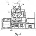
- FIG. 4shows a front view of an exemplary microscope 110 of microscope imaging unit 202.
- a set of viewing oculars 173 of microscope 110are optionally located on microscope 110 for operator viewing.
- microscope 110further includes a camera 118 for acquiring images.
- Illumination light source 126 in FIG. 4projects light onto X-Y stage 177, which is subsequently imaged through microscope 110 and acquired through CCD camera 118 for processing in an image processor.
- a Z stage or focus stage 179 under control of microscope controller 112provides displacement in the Z plane for focusing.
- Microscope 110further includes motorized objective turret 128 for selection of objectives.
- microscope 110comprises a LCMD unit, such as a near IR laser diode integral with the microscope optics, such that microscope imaging unit 202 and LCMD unit 208 comprise a single piece of equipment.
- a glass slideis scanned to create a digital slide.
- a standard microscope slidehaving at least one biological sample deposited thereon and optionally stained with one or more chromogenic dyes is positioned on automated X-Y stage 177 of microscope 110, depicted in FIG. 4 .
- an image scan operationis performed wherein the slide can be scanned at one or more resolutions and magnifications based upon image-processing algorithms and image analysis algorithms executed by controller 112. Examples of such image acquisition can be found in US 2006/0002636 A1 entitled “Data Structure of an Image Storage and Retrieval System” and US 2005/0089208 A1 entitled “System and Method for Generating Digital Images of a Microscope Slide”.
- the slide image data for that particular slideis transmitted to controller 112 and stored in storage medium 204, i.e. in a database on a remotely available server such that remote users networked to the server can access the slide image data.
- microscope imaging unit 202can be configured to operate autonomously. That is, a clinician can initiate microscope imaging unit 202 such that microscope imaging unit 202 thereafter operates automatically without the need for human intervention as long as a supply of microscope slides is available at its in-feed stage and no system errors occur. Alternately, the clinician and/or the controller can manually feed slides into the microscope imaging system.
- the digital slideis a digital representation of the slide image data of all or substantially all of a sample on a glass slide that was captured during scanning.
- the slide image datais digitized such that mechanical stage coordinates of the captured area(s) are represented.
- This coordinate informationcan be stored inside the image data file (.TIFF or JPG) or can be a separate file for example located in storage medium 204 on the database. Other methods of storing positional information are also possible. This provides sufficient information such that a particular pixel coordinate on a digital slide can be converted to mechanical stage, i.e. real world x-y coordinates.
- Other informationmay also be contained in storage medium 204, such as, for example, varied patient and health care provider information, including, but not limited to, the patient's name, age, and address, and the physician's name and location of practice, slide identification such as barcode information, microscope identification, and any of a variety of information.
- varied patient and health care provider informationincluding, but not limited to, the patient's name, age, and address, and the physician's name and location of practice, slide identification such as barcode information, microscope identification, and any of a variety of information.
- storage medium 204can also include coordinates with respect to a coordinate system, such as a Cartesian coordinate system comprised of x and y coordinates that are oriented relative to a reference point on the slide.
- a coordinate systemsuch as a Cartesian coordinate system comprised of x and y coordinates that are oriented relative to a reference point on the slide.
- the process of capturing and inserting these coordinates into storage medium 204is referred to as the "registration” process.
- the registration process of these coordinatescan occur after the image capture process is complete (referred to as "offline").
- Visualization unit 206can include, for example, a computer with access to storage medium 204, such as a computer networked to remote database.
- the computercan have software installed thereon to access, view, and edit the image data stored in storage medium 204.
- the usercan access storage medium 204 remotely, and view the digital slide on any of a number of networked computers having a visualization unit 206.
- the userthen identifies cells or areas of interest, using a selection tool.
- the corresponding digital coordinates describing this area of interest, such as pixel and/or rectangular coordinates,can then be stored to storage medium 204.
- the digital slidecan be annotated with a variety of drawing tools such as freehand drawing, text boxes, circle, rectangle, and polygon, and the like.
- the annotation datasuch as the coordinates describing the annotation, are stored in the database, an xml file, and/or as metadata inside the digital slide file.
- visualization unit 206can provide automated or semi-automated assistance to the user.
- unit 206can separate epithelium from stroma and auto-generate an annotation. This semi-automated or automated assistance is explained, for example, in previously referenced US 6215892 B1 entitled “Method and Apparatus for Automated Image Analysis of Biological Specimens.”
- the usercan then edit this annotation.
- Such editscan include change the shape of the annotation or alternatively drawing an exclusionary annotation the deletes a certain portion of the area in the annotation. For example, if the semi-automated system created a free hand drawing, the user can draw another free hand drawing. The area defined by this second freehand drawing is subtracted from the area of the first such that the overlap is eliminated from the first and only the non-overlapping area of the first is left.
- LCMD unit 208understands mechanical coordinates, such as Cartesian coordinates or rectangular coordinates, corresponding to its x-y stage system.
- a stage mapping calibrationthat would be performed periodically on microscope imaging unit 202, or the digital slide scanning system, and LCMD unit 208 provides the transformation information necessary to construct a transform matrix.
- This transform matrixcan be combined with a digital slide pixel to scanner stage matrix in order to provide transformation of the annotation pixel coordinates to LCMD stage coordinates.
- system 200transposes the positions into actual stage coordinates for the LCMD procedure.
- a program running on LCMD unit 208controls the operation by communicating with a stage controller, similar to the stage controller of microscope imaging unit 202.
- embodiments of the present disclosurecan also include a step to perform a manual or dynamic, automated registration or alignment of the digital slide and the field of view of the LCMD using the transformed coordinates as a starting point.
- LCMD unit 208typically has a camera on the unit, such as when microscope imaging unit 202 and LCMD unit 208 comprise the same unit, an image of the specified area on the glass slide can be captured before LCMD is performed. This image can then be compared to the original annotated area of the digital slide.
- the comparisonis done automatically.
- This automatic comparisoncan be done by doing a normalized cross correlation. This comparison can be repeated using a sliding window of a predetermined amount to find the best match.
- the stage coordinates for transfercan then be adjusted. Stage coordinates describing the area to be captured can be optionally padded by a predetermined amount in order to compensate for any mechanical inaccuracies that can be in the system. Such padding can be different in each axis to reflect the potentially different accuracies of each axis.
- the comparisonis done manually by the LCMD operator.
- the manual registration of the digital slidecan be accomplished via a side-by-side comparison of the digital slide and LCMD unit field of view, a transparent overlay comparison, or a combination of both.
- Registration of the images using either the side-by-side and overlay techniques, such as transparent overlaycan be accomplished by a user interface and a user input device, such as a mouse, joystick, keyboard, and the like, which allows an operator to adjust any of a variety of parameters on the LCMD unit field of view including movement, sizing, and/or scaling of the annotation, movement of the image, adjustment of scale or magnification of the image, and any combination thereof.
- the movement of the annotation, image, or bothcan include x-y translation, as well as rotational movement.
- FIGS. 5a and 5brepresent an example of manual registration 500 using a side-by-side comparison technique in which the annotation, i.e. the boxed area in this case, can be moved.
- FIG. 5aillustrates a side-by- side screen shot 500a of an initial registration of digital slide image 506 having annotation 502 and LCMD unit image 508 having annotation 504.
- the initial registration of annotation 502 and 504is poor, and does not represent the same or similar selected area of interest.
- the userthrough a user interface, moves and/or sizes annotation 504 to improve the registration, as illustrated in FIG. 5b in screen shot 500b, such that the selected areas of interest are the same or similar in both images 506 and 508.
- Movement of annotation 504can include x-y translation as well as rotational movement.
- the scale of the annotationcan be adjusted. If the initial scale of the annotation of the LCMD unit image is different from the scale of the annotation of the digital slide, the user can adjust the scale of the annotation using a user input device, such as a mouse, until the scale of the two views are substantially similar.
- a user input devicesuch as a mouse
- FIGS. 6a and 6brepresent an example of manual registration 600 using a side-by-side comparison technique in which LCMD unit image 608 can be moved to register annotations 602 and 604.
- FIG. 6aillustrates a side-by-side screen shot 600a of an initial registration of digital slide image 606 having annotation 602 and LCMD unit image 608 having annotation 604.
- the initial registration of annotation 602 and 604is poor, and does not represent the same or similar selected area of interest.
- the userthrough a user interface, moves LCMD unit image 608 to improve the registration, as illustrated in FIG. 5b in screen shot 600b, such that the selected areas of interest are the same or similar in both images 606 and 608.
- Movement of LCMD unit image 608can include x-y translation as well as rotational movement.
- the scale or magnification of LCMD unit image 608can be made smaller or larger such that LCMD unit image 608 is approximately the same magnification of digital slide image 606.
- the scale between the digital slide and the LCMD unit imagecan be automatically adjusted such that it is not dependent upon the user's manual adjustment.
- This automatic scale adjustmentcan be accomplished via a distance/pixel calibration, for example.
- the scale of the one or both of the digital slide and the LCMD unit imagecan be adjusted so that one screen pixel corresponds to the same distance, such as a ⁇ m distance, in both images.
- This automatic scale adjustmentcan be incorporated in the registration system in which the annotation is moved or adjusted and the registration system in which the LCMD unit image is moved or adjusted.
- LCMD unit 208can comprise, for example, a near IR laser diode integral with the microscope optics.
- the pulsed laser beamactivates a precise spot on the transfer film, fusing the film with the underlying isolated cells.
- the transfer film with the bonded cellsis then lifted off the thin tissue section, leaving the other, non-isolated cells on the glass slide.
- the isolated cellscan then be analyzed as discussed in the Background section.
- the microscope operator activating LCMD unit 208need not be an expert in the area of cell identification, and can be a lab technician as compared to a pathologist. Therefore, the system and method of the present invention does not constrain an expert, such as a pathologist, to an LCMD unit for long periods of time. Rather, the pathologist or expert can identify areas of interest at their leisure, and at any location in which they have editing and selecting access to storage medium 204 and the digital slide image data.
Landscapes
- Physics & Mathematics (AREA)
- General Physics & Mathematics (AREA)
- Chemical & Material Sciences (AREA)
- Analytical Chemistry (AREA)
- Optics & Photonics (AREA)
- Multimedia (AREA)
- Engineering & Computer Science (AREA)
- Health & Medical Sciences (AREA)
- Computer Vision & Pattern Recognition (AREA)
- Life Sciences & Earth Sciences (AREA)
- Biochemistry (AREA)
- General Health & Medical Sciences (AREA)
- Immunology (AREA)
- Pathology (AREA)
- Microscoopes, Condenser (AREA)
Description
- The invention relates generally to microdissection. More particularly, the invention relates to a system and method for designating and capturing targets of interest for microdissection according to the preamble of
claim 1 or 3. - Laser Capture Microdissection ("LCMD") is a technology for isolating individual cells or specific cells of interest from microscopic regions of a sample. One method of performing LCMD is to apply a transfer film to the surface of a tissue section. Under a microscope, the thin tissue section is viewed through a glass slide on which it is mounted and individual cells or clusters of cells are identified for isolation. When the isolated cells are in the field of view, the microscope operator actives a near IR laser diode integral with the microscope optics. The pulsed laser beam activates a precise spot on the transfer film, fusing the film with the underlying isolated cells. The transfer film with the bonded cells is then lifted off the thin tissue section, leaving the other, non-isolated cells on the glass slide.
- LCMD can be performed on a variety of tissue samples including blood smears, cytologic preparations, cell cultures, aliquots of solid tissues, and frozen and paraffin embedded archival tissues. These individual cells can then be analyzed using a variety of techniques to analyze their various constituents by such techniques as Polymerase Chain Reaction ("PCR"), immunoassays, microarrays, or the like. This has proven valuable in research by enabling very precise molecular assays to be performed without compromising the ability to target particular cells. Further, because LCMD does not alter or damage the morphology and chemistry of the sample collected, nor the surrounding cells, LCMD is a useful method of collecting selected cells for DNA, RNA, and protein analyses.
- A LCMD system according to the preamble of
claim 1 is known fromUS 2007/0066967 A1 orWO 2004/025569 A2 . - However, the process of identifying cells can be very tedious requiring an individual to sit at the microscope and manually identify each cell. If multiple people want to use the system, they have to each schedule time on the unit. Furthermore, the individual performing LCMD must be trained in the identification of the cells of interest. This can make higher volume applications much less practical and much more expensive, as well as creating a constraint on experts whose time and location limitations might not be amenable to such a workflow.
- There remains a need for a system that allows identification of the specified cells of interest to be performed independently from the LCMD process.
- The invention is defined by
claim 1 and 3. Embodiments of the present invention resolve many of the above-described deficiencies and drawbacks, and are directed to a system and method for obtaining samples from a laser capture microdissection system. A slide, such as a glass slide, containing a tissue or the like sample can be scanned to create a digital slide. The digital slide can then be annotated by a user, such as an expert in cell identification. The coordinates of the annotations can then be subject to a transformation, such that the designated area is laser dissected out on a laser capture microdissection device, independently and discretely from the cell identification process. - In an embodiment of the invention, the digital slide having a first annotation representing an area of interest is compared to an image produced by the laser capture microdissection unit having a second annotation representing a portion of the biological sample before LCMD is performed. The image comparison is done via side-by-side comparison or transparent overlay. The first and second annotations are initially registered based on the coordinate transformation. The first and second annotations can then be precisely registered by either movement of the second annotation or movement of the image produced by the laser capture microdissection unit until the portion of biological sample represented by the second annotation substantially corresponds to the area of interest previously selected on the digital slide.
- The above summary of the invention is not intended to describe each illustrated embodiment or every implementation of the present invention. The figures and the detailed description that follow more particularly exemplify these embodiments.
FIG. 1 is a flow diagram of a method of utilizing a digital slide to identify regions of interest according to an embodiment.FIG. 2 is a block diagram of a laser capture microdissection system according to an embodiment of the invention.FIG. 3 is a schematic of a microscope imaging system according to an embodiment of the invention.FIG. 4 is a front view of a microscope of the microscope imaging system ofFIG. 3 .FIG. 5a is a screen shot of a side-by-side comparison of an initial registration of the digital slide and the LCMD unit field of view.FIG. 5b is a screen shot of the side-by- side comparison ofFIG. 5a after moving the annotation on the LCMD unit field of view.FIG. 6a is a screen shot of a side-by-side comparison of an initial registration of the digital slide and the LCMD unit field of view.FIG. 6b is a screen shot of the side-by-side comparison ofFIG. 6a after moving the image on the LCMD unit.- Embodiments of the present disclosure provide a mechanism to utilize a digital slide to identify regions of interest. The glass slide corresponding to the digital slide can be placed on a LCMD unit. Coordinates for areas of interest identified on the digital slide can be subject to a transformation matrix that translates coordinates on the digital slide to coordinates on the glass slide on the LCMD unit. The LCMD unit can then dissect out the desired areas.
FIG. 1 illustrates a flow diagram 10 of an LCMD method, utilizing a digital slide. At 12, a glass slide is scanned to create a digital slide. The digital slide is stored remotely in a database on a remote server. The digital slide is then analyzed at 14 to identify cells of interest for further analysis. The analysis is done not on the same microscope system, but remotely. At 14, areas of interest are identified on the digital slide and optionally annotated. In one embodiment of the invention,cell identification 14 is performed manually by a pathologist, lab technician, or other such individual trained in the identification of cells. In another embodiment of the invention,cell identification 14 is performed automatically, as discussed inUS 6215892 B1 entitled "Method and Apparatus for Automated Image Analysis of Biological Specimens".- To perform LCMD, the glass slide corresponding to the digital slide is placed on a stage of the LCMD unit at 16. At 18, the coordinates of the identified areas of interest are then subject to a transformation matrix, transforming the coordinates of the digital slide, i.e. pixel information, to the corresponding coordinates, i.e. X-Y coordinates, on the stage of the LCMD unit. At 20, the LCMD unit is activated by an individual that is the same as or separate from the individual who performed the cell identification to dissect out the desired areas or cells of interest.
FIG. 2 illustrates a lasercapture microdissection system 200, according to embodiments of the present invention, including amicroscope imaging unit 202, astorage medium 204 such as a database, avisualization unit 206, and anLCMD unit 208.Microscope imaging unit 202 andLCMD unit 208 can be one in the same unit, i.e. a microscope comprising both a scanning feature and an LCMD feature, or separate and distinct units.Storage medium 204 comprises a remote server that is networked tomicroscope imaging unit 202,visualization unit 206, andLCMD unit 208, such thatvisualization unit 206 is positioned remotely frommicroscope imaging unit 202 andLCMD unit 208, and can be used to access and view the image data stored instorage medium 204.- Each unit of
system 200 is described in more detail below. FIG. 3 illustrates an exemplary high-level functional diagram of amicroscope imaging unit 202, according to an embodiment of the invention.Microscope imaging unit 202 includes amicroscope 110 electrically connected to acontroller 112 having adisplay device 114.Controller 112 inFIG. 3 can be any special-purpose or conventional computer, such as a desktop, laptop, or host computer.Controller 112 is loaded with the appropriate software for controllingmicroscope imaging unit 202, such as software for running image-processing algorithms, LCMD algorithms, and/or image analysis algorithms.Display device 114 can be any special-purpose or conventional computer display device that outputs graphical images to a user.Microscope 110 can further include abarcode reader 116, acamera 118, aserial interface 120, one ormore sensors 122, one ormore motors 124, alight source 126, aturret 128, and adata interface 130.Camera 118 can be a digital camera having selectable resolution capabilities. Furthermore,camera 118 can comprise any type of device suitable for gathering an image.Camera 118 is mounted upon aturret 128 ofmicroscope 110 such that an aperture ofcamera 118 is aligned with the field of view (FOV) of any lens associated withturret 128.Camera 118 is electrically coupled to a serial interface such that they can feed electrical inputs to aserial interface 120, which facilitates a serial communication link betweencamera 118 andcontroller 112. In an embodiment of the invention,serial interface 120 provides a USB connection tocontroller 1 12. It should be appreciated thatcamera 1 18 can be communicatively coupled tocontroller 112 in other manners.Controller 112 can include one or more components for facilitating its functions. In an embodiment, controller includes avideo card 112.Camera 118 provides a direct video output to the video card withincontroller 112. The video card gathers the image data fromcamera 118 for processing in a well-known manner.- The sensors can include one or more sensors for sensing various aspects of
microscope imaging unit 202. For example,sensors 122 include, but are not limited to, position sensors, temperature sensors, and light intensity sensors or optical encoders.Motors 124 can be any type of motors for providing motion to the microscope or any portion of the microscope. In an embodiment,motors 124 are conventional servomotors associated with the motion control ofmicroscope 110, such as those for rotating the appropriately powered lens within the optical path ofmicroscope 110, for adjusting focus, or for controlling an automated X, Y stage (shown inFIG. 4 ). Light source 126 can be any suitable light source for appropriately illuminating the FOV ofmicroscope 110 sufficient to create a digital image of that FOV.Turret 128 is a conventional motor-driven microscope turret upon which is mounted a set of lenses of varying power that may be rotated into the optical path ofmicroscope 110.Turret 128 is also suitably controlled to provide the desired focus.Sensors 122,motors 124,light source 126, andturret 128 feed to the electrical inputs ofdata interface 130.Data interface 130 can be a conventional system driver card, which facilitates a data communication link between these elements and a motion control card withincontroller 112.FIG. 4 shows a front view of anexemplary microscope 110 ofmicroscope imaging unit 202. A set ofviewing oculars 173 ofmicroscope 110 are optionally located onmicroscope 110 for operator viewing. As mentioned,microscope 110 further includes acamera 118 for acquiring images. Illuminationlight source 126 inFIG. 4 projects light ontoX-Y stage 177, which is subsequently imaged throughmicroscope 110 and acquired throughCCD camera 118 for processing in an image processor. A Z stage or focus stage 179 under control ofmicroscope controller 112 provides displacement in the Z plane for focusing.Microscope 110 further includes motorizedobjective turret 128 for selection of objectives. In one embodiment of the invention,microscope 110 comprises a LCMD unit, such as a near IR laser diode integral with the microscope optics, such thatmicroscope imaging unit 202 andLCMD unit 208 comprise a single piece of equipment.- Referring back to
FIG. 1 , at 12, a glass slide is scanned to create a digital slide. In particular, a standard microscope slide having at least one biological sample deposited thereon and optionally stained with one or more chromogenic dyes is positioned on automatedX-Y stage 177 ofmicroscope 110, depicted inFIG. 4 . - Once the slide is positioned in the FOV of
microscope 110, an image scan operation is performed wherein the slide can be scanned at one or more resolutions and magnifications based upon image-processing algorithms and image analysis algorithms executed bycontroller 112. Examples of such image acquisition can be found inUS 2006/0002636 A1 entitled "Data Structure of an Image Storage and Retrieval System" andUS 2005/0089208 A1 entitled "System and Method for Generating Digital Images of a Microscope Slide". Upon completion of the image scan operation, the slide image data for that particular slide is transmitted tocontroller 112 and stored instorage medium 204, i.e. in a database on a remotely available server such that remote users networked to the server can access the slide image data. - It should be appreciated that
microscope imaging unit 202 can be configured to operate autonomously. That is, a clinician can initiatemicroscope imaging unit 202 such thatmicroscope imaging unit 202 thereafter operates automatically without the need for human intervention as long as a supply of microscope slides is available at its in-feed stage and no system errors occur. Alternately, the clinician and/or the controller can manually feed slides into the microscope imaging system. - The digital slide is a digital representation of the slide image data of all or substantially all of a sample on a glass slide that was captured during scanning. In one embodiment, the slide image data is digitized such that mechanical stage coordinates of the captured area(s) are represented. This coordinate information can be stored inside the image data file (.TIFF or JPG) or can be a separate file for example located in
storage medium 204 on the database. Other methods of storing positional information are also possible. This provides sufficient information such that a particular pixel coordinate on a digital slide can be converted to mechanical stage, i.e. real world x-y coordinates. Other information may also be contained instorage medium 204, such as, for example, varied patient and health care provider information, including, but not limited to, the patient's name, age, and address, and the physician's name and location of practice, slide identification such as barcode information, microscope identification, and any of a variety of information. - As mentioned above,
storage medium 204 can also include coordinates with respect to a coordinate system, such as a Cartesian coordinate system comprised of x and y coordinates that are oriented relative to a reference point on the slide. The process of capturing and inserting these coordinates intostorage medium 204 is referred to as the "registration" process. The registration process of these coordinates can occur after the image capture process is complete (referred to as "offline"). - Referring back to
FIG. 1 , after digitization of the slide at 12, a user such as a pathologist views the slide at 14 usingvisualization unit 206.Visualization unit 206 can include, for example, a computer with access tostorage medium 204, such as a computer networked to remote database. The computer can have software installed thereon to access, view, and edit the image data stored instorage medium 204. - The user can access
storage medium 204 remotely, and view the digital slide on any of a number of networked computers having avisualization unit 206. The user then identifies cells or areas of interest, using a selection tool. The corresponding digital coordinates describing this area of interest, such as pixel and/or rectangular coordinates, can then be stored tostorage medium 204. - The digital slide can be annotated with a variety of drawing tools such as freehand drawing, text boxes, circle, rectangle, and polygon, and the like. The annotation data, such as the coordinates describing the annotation, are stored in the database, an xml file, and/or as metadata inside the digital slide file.
- In yet another embodiment,
visualization unit 206 can provide automated or semi-automated assistance to the user. For example,unit 206 can separate epithelium from stroma and auto-generate an annotation. This semi-automated or automated assistance is explained, for example, in previously referencedUS 6215892 B1 entitled "Method and Apparatus for Automated Image Analysis of Biological Specimens." The user can then edit this annotation. Such edits can include change the shape of the annotation or alternatively drawing an exclusionary annotation the deletes a certain portion of the area in the annotation. For example, if the semi-automated system created a free hand drawing, the user can draw another free hand drawing. The area defined by this second freehand drawing is subtracted from the area of the first such that the overlap is eliminated from the first and only the non-overlapping area of the first is left. - Referring back to
FIG. 1 at 18, in order to perform LCMD on the areas of interest identified in 16, the annotations generally must be converted to coordinates readable byLCMD unit 208. In some embodiments,LCMD unit 208 understands mechanical coordinates, such as Cartesian coordinates or rectangular coordinates, corresponding to its x-y stage system. A stage mapping calibration that would be performed periodically onmicroscope imaging unit 202, or the digital slide scanning system, andLCMD unit 208 provides the transformation information necessary to construct a transform matrix. This transform matrix can be combined with a digital slide pixel to scanner stage matrix in order to provide transformation of the annotation pixel coordinates to LCMD stage coordinates. - At the completion of the cell identification,
system 200 transposes the positions into actual stage coordinates for the LCMD procedure. A program running onLCMD unit 208 controls the operation by communicating with a stage controller, similar to the stage controller ofmicroscope imaging unit 202. - Before LCMD is performed, embodiments of the present disclosure can also include a step to perform a manual or dynamic, automated registration or alignment of the digital slide and the field of view of the LCMD using the transformed coordinates as a starting point. Because
LCMD unit 208 typically has a camera on the unit, such as whenmicroscope imaging unit 202 andLCMD unit 208 comprise the same unit, an image of the specified area on the glass slide can be captured before LCMD is performed. This image can then be compared to the original annotated area of the digital slide. - In one embodiment of the invention, the comparison is done automatically. This automatic comparison can be done by doing a normalized cross correlation. This comparison can be repeated using a sliding window of a predetermined amount to find the best match. Once the coordinates of the best match are determined, the stage coordinates for transfer can then be adjusted. Stage coordinates describing the area to be captured can be optionally padded by a predetermined amount in order to compensate for any mechanical inaccuracies that can be in the system. Such padding can be different in each axis to reflect the potentially different accuracies of each axis.
- In another embodiment of the invention, the comparison is done manually by the LCMD operator. The manual registration of the digital slide can be accomplished via a side-by-side comparison of the digital slide and LCMD unit field of view, a transparent overlay comparison, or a combination of both. Registration of the images using either the side-by-side and overlay techniques, such as transparent overlay, can be accomplished by a user interface and a user input device, such as a mouse, joystick, keyboard, and the like, which allows an operator to adjust any of a variety of parameters on the LCMD unit field of view including movement, sizing, and/or scaling of the annotation, movement of the image, adjustment of scale or magnification of the image, and any combination thereof. The movement of the annotation, image, or both can include x-y translation, as well as rotational movement.
- According to one embodiment of the invention,
FIGS. 5a and 5b represent an example of manual registration 500 using a side-by-side comparison technique in which the annotation, i.e. the boxed area in this case, can be moved.FIG. 5a illustrates a side-by- side screen shot 500a of an initial registration ofdigital slide image 506 havingannotation 502 andLCMD unit image 508 havingannotation 504. As apparent inFIG. 5a , the initial registration ofannotation FIG. 5b in screen shot 500b, such that the selected areas of interest are the same or similar in bothimages annotation 504 can include x-y translation as well as rotational movement. - In another embodiment of the invention, the scale of the annotation can be adjusted. If the initial scale of the annotation of the LCMD unit image is different from the scale of the annotation of the digital slide, the user can adjust the scale of the annotation using a user input device, such as a mouse, until the scale of the two views are substantially similar.
- According to an alternative embodiment of the invention,
FIGS. 6a and 6b represent an example of manual registration 600 using a side-by-side comparison technique in whichLCMD unit image 608 can be moved to registerannotations FIG. 6a illustrates a side-by-side screen shot 600a of an initial registration ofdigital slide image 606 havingannotation 602 andLCMD unit image 608 havingannotation 604. As apparent inFIG. 6a , the initial registration ofannotation LCMD unit image 608 to improve the registration, as illustrated inFIG. 5b in screen shot 600b, such that the selected areas of interest are the same or similar in bothimages LCMD unit image 608 can include x-y translation as well as rotational movement. In addition, the scale or magnification ofLCMD unit image 608 can be made smaller or larger such thatLCMD unit image 608 is approximately the same magnification ofdigital slide image 606. - In another embodiment of the invention, the scale between the digital slide and the LCMD unit image can be automatically adjusted such that it is not dependent upon the user's manual adjustment. This automatic scale adjustment can be accomplished via a distance/pixel calibration, for example. The scale of the one or both of the digital slide and the LCMD unit image can be adjusted so that one screen pixel corresponds to the same distance, such as a µm distance, in both images. This automatic scale adjustment can be incorporated in the registration system in which the annotation is moved or adjusted and the registration system in which the LCMD unit image is moved or adjusted.
- Referring back to
FIG. 1 at 20, when the isolated cells are in the field of view, and the user is satisfied with the annotation registration and scale, the microscope operator activatesLCMD unit 208.LCMD unit 208 can comprise, for example, a near IR laser diode integral with the microscope optics. The pulsed laser beam activates a precise spot on the transfer film, fusing the film with the underlying isolated cells. The transfer film with the bonded cells is then lifted off the thin tissue section, leaving the other, non-isolated cells on the glass slide. The isolated cells can then be analyzed as discussed in the Background section. - The microscope operator activating
LCMD unit 208 need not be an expert in the area of cell identification, and can be a lab technician as compared to a pathologist. Therefore, the system and method of the present invention does not constrain an expert, such as a pathologist, to an LCMD unit for long periods of time. Rather, the pathologist or expert can identify areas of interest at their leisure, and at any location in which they have editing and selecting access tostorage medium 204 and the digital slide image data. - The embodiments above are intended to be illustrative and not limiting.
Claims (5)
- A system for designating and capturing targets of interest on a slide having a biological sample contained thereon, the system (200) comprising:a microscope imaging unit (202) including a microscope (110) having a stage (177) for positioning the slide thereon, and an image capturing apparatus (118), wherein the image capturing apparatus (118) generates a digital image representation of at least a portion of the biological sample;a visualization unit (206) including a computer having a display screen, the computer having a selection tool installed thereon, the selection tool being adapted to enable a user to select at least one area of interest from the digital image representation;a laser capture microdissection unit (208) adapted to dissect a portion from the biological sample, anda storage medium (204) comprising a remote server that is networked to the microscope imaging unit (202), the visualization unit (206) and the laser capture microdissection unit (208),characterized in thatthe microscope imaging unit (202) stores the digital image representation in a database on the remote server,the visualization unit (206) is remote and separate from the microscope imaging unit (202) and the laser capture microdissection unit (208) and is usable to access and view the digital image representation stored in the database, wherein a first set of coordinates is generated and stored in the database on the remote server by the visualization unit (206) upon selection of the at least one area of interest, and wherein the first set of coordinates is transformed to a second set of coordinates corresponding to positions on the slide and readable by the laser capture microdissection unit (208) such that the dissected portion of the biological sample corresponds to the at least one area of interest selected from the digital image representation,wherein an executable program configured for transforming the first set of coordinates to the second set of coordinates is stored on the remote server.
- The system of claim 1, wherein the first set of coordinates describes the at least one area of interest and comprises pixel coordinates and/or rectangular coordinates, and wherein the second set of coordinates comprises Cartesian coordinates corresponding to positions on a stage of the laser capture microdissection unit (208).
- A method for designating and capturing targets of interest on a slide having a biological sample contained thereon, the method comprising:providing a slide having a biological sample thereon;generating a digital image representation of at least a portion of the biological sample (12) by using a microscope imaging unit (202);selecting at least one area of interest from the digital image representation (506,14) by using a visualization unit (206), thereby generating a first set of coordinates;placing the slide having the biological sample thereon on a laser capture microdissection unit (208,16) anddissecting a portion of the biological sample corresponding to the at least one area of interest selected from the digital image representation (20);wherein the method ischaracterized byproviding the visualization unit (206) remote and separate from the microscope imaging unit (202) and the laser capture microdissection unit (208),selecting the at least one area of interest comprisesstoring the digital image representation to a remote server;accessing remotely the digital image representation stored on the remote server;viewing the digital image representation on the visualization unit (206) at a location remote from the microscope imaging unit (202) and the laser capture microdissection unit (208); andstoring the first set of coordinates to the remote server; andtransforming the first set of coordinates to a second set of coordinates by using an executable program configured for transforming the first set of coordinates to the second set of coordinates and stored on the remote server, wherein the second set of coordinates is readable by the laser capture microdissection unit (208,18).
- The method of claim 3, wherein the first set of coordinates describes the at least one area of interest and comprises pixel coordinates and/or rectangular coordinates, and wherein the second set of coordinates comprises Cartesian coordinates corresponding to positions on a stage of the laser capture microdissection unit (208).
- The method of claim 3, further comprising analyzing the dissected portion of the biological sample, in particular by using at least one technique selected from the group consisting of Polymerase Chain Reaction ("PCR"), immunoassays, microarrays, and combinations thereof.
Applications Claiming Priority (2)
| Application Number | Priority Date | Filing Date | Title |
|---|---|---|---|
| US1735307P | 2007-12-28 | 2007-12-28 | |
| PCT/US2008/088451WO2009086521A2 (en) | 2007-12-28 | 2008-12-29 | System, device, and method for laser capture microdissection |
Publications (4)
| Publication Number | Publication Date |
|---|---|
| EP2235578A2 EP2235578A2 (en) | 2010-10-06 |
| EP2235578A4 EP2235578A4 (en) | 2011-12-14 |
| EP2235578B1 EP2235578B1 (en) | 2020-06-03 |
| EP2235578B2true EP2235578B2 (en) | 2023-09-13 |
Family
ID=40825105
Family Applications (1)
| Application Number | Title | Priority Date | Filing Date |
|---|---|---|---|
| EP08867252.2AActiveEP2235578B2 (en) | 2007-12-28 | 2008-12-29 | System, device, and method for laser capture microdissection |
Country Status (2)
| Country | Link |
|---|---|
| EP (1) | EP2235578B2 (en) |
| WO (1) | WO2009086521A2 (en) |
Families Citing this family (7)
| Publication number | Priority date | Publication date | Assignee | Title |
|---|---|---|---|---|
| JP5734588B2 (en)* | 2010-07-15 | 2015-06-17 | オリンパス株式会社 | Cell observation apparatus and observation method |
| US20120189803A1 (en)* | 2011-01-21 | 2012-07-26 | Albany International Corp. | Ultra-resilient pad and method of making thereof |
| CN113406077A (en)* | 2012-10-03 | 2021-09-17 | 皇家飞利浦有限公司 | Combined sample inspection |
| DE102013209880A1 (en)* | 2013-05-28 | 2014-12-04 | Leica Microsystems Cms Gmbh | Method for laser microdissection and laser microdissection system |
| DE102015108017A1 (en)* | 2015-05-20 | 2016-11-24 | Leica Microsystems Cms Gmbh | Method and examination system for examining and processing a microscopic sample |
| GB2543273A (en)* | 2015-10-12 | 2017-04-19 | Leica Microsystems Cambridge Ltd | Obtaining biological information and storing and searching biological information in a database |
| WO2020146037A1 (en)* | 2019-01-09 | 2020-07-16 | Google Llc | Augmented reality laser capture microdissection machine |
Citations (5)
| Publication number | Priority date | Publication date | Assignee | Title |
|---|---|---|---|---|
| WO2000007131A1 (en)† | 1998-07-30 | 2000-02-10 | Arcturus Engineering, Inc. | Medical diagnostic and treatment information system and method |
| EP1367380A1 (en)† | 2002-05-02 | 2003-12-03 | Sedlmayr, Peter | Method and apparatus for automatically localising and manipulating cells |
| US20040085443A1 (en)† | 2000-12-13 | 2004-05-06 | Kallioniemi Olli P | Method and system for processing regions of interest for objects comprising biological material |
| US20040093166A1 (en)† | 2002-09-13 | 2004-05-13 | Kil David H. | Interactive and automated tissue image analysis with global training database and variable-abstraction processing in cytological specimen classification and laser capture microdissection applications |
| US20070160280A1 (en)† | 2004-05-11 | 2007-07-12 | P.A.L.M. Microlaser Technologies Gmbh | Method for processing a material by means of a laser irradiation and control system |
Family Cites Families (4)
| Publication number | Priority date | Publication date | Assignee | Title |
|---|---|---|---|---|
| US6469779B2 (en)* | 1997-02-07 | 2002-10-22 | Arcturus Engineering, Inc. | Laser capture microdissection method and apparatus |
| WO2001033190A2 (en)* | 1999-11-04 | 2001-05-10 | Arcturus Engineering, Inc. | Automated laser capture microdissection |
| AU2003218116A1 (en)* | 2002-03-12 | 2003-09-29 | Beth Israel Deaconess Medical Center | Medical imaging systems |
| US9217694B2 (en)* | 2003-10-21 | 2015-12-22 | Leica Microsystems Cms Gmbh | Method for automatically generating laser cutting lines in laser microdissection processes |
- 2008
- 2008-12-29EPEP08867252.2Apatent/EP2235578B2/enactiveActive
- 2008-12-29WOPCT/US2008/088451patent/WO2009086521A2/enactiveApplication Filing
Patent Citations (5)
| Publication number | Priority date | Publication date | Assignee | Title |
|---|---|---|---|---|
| WO2000007131A1 (en)† | 1998-07-30 | 2000-02-10 | Arcturus Engineering, Inc. | Medical diagnostic and treatment information system and method |
| US20040085443A1 (en)† | 2000-12-13 | 2004-05-06 | Kallioniemi Olli P | Method and system for processing regions of interest for objects comprising biological material |
| EP1367380A1 (en)† | 2002-05-02 | 2003-12-03 | Sedlmayr, Peter | Method and apparatus for automatically localising and manipulating cells |
| US20040093166A1 (en)† | 2002-09-13 | 2004-05-13 | Kil David H. | Interactive and automated tissue image analysis with global training database and variable-abstraction processing in cytological specimen classification and laser capture microdissection applications |
| US20070160280A1 (en)† | 2004-05-11 | 2007-07-12 | P.A.L.M. Microlaser Technologies Gmbh | Method for processing a material by means of a laser irradiation and control system |
Non-Patent Citations (11)
| Title |
|---|
| "Leica Image Manager", THE PROFESSIONAL IMAGE MANAGEMENT SYSTEM, 2002† |
| "Leica LMD6000 Laser Mikrodissection System Software Version 6.3", LEICA MICROSYSTEMS, pages 1 - 68† |
| "Leica LMD6000 Laser Mikrodissection System Upgrade modules", pages 1 - 25† |
| "Leica LMD6000 Laser Mikrodissection System", INSTRUCTIONS, October 2006 (2006-10-01), pages 1 - 46† |
| 'Control of a Remote Microscope over the Internet', R. Maturo et al, Bio Techniques vol.22, p.1154-1157, June 1997† |
| ESPINA VIRGINIA ET AL: "Laser-capture microdissection", NATURE PROTOCOLS, vol. 1, no. 2, 1 August 2006 (2006-08-01), pages 586 - 603† |
| Information Document "Remote support tool. SYS-remote", Business Unit Communication- Leica. Microsystems. 07.02.05† |
| Instruction Manual SYS Remote† |
| MCCULLOUGH BRUCE ET AL: "Digital Microscopy Imaging and New Approaches in Toxicologic Pathology", TOXICOLOGIC PATHOLOGY, vol. 32, no. 2_suppl, 1 February 2004 (2004-02-01), pages 49 - 58† |
| 'Region of interest', Wikipedia 25.10.07† |
| Servicekonzept LMD6000† |
Also Published As
| Publication number | Publication date |
|---|---|
| WO2009086521A3 (en) | 2009-10-01 |
| EP2235578A4 (en) | 2011-12-14 |
| EP2235578A2 (en) | 2010-10-06 |
| EP2235578B1 (en) | 2020-06-03 |
| WO2009086521A2 (en) | 2009-07-09 |
Similar Documents
| Publication | Publication Date | Title |
|---|---|---|
| US12228723B2 (en) | Point-of-care-computational microscopy based-systems and methods | |
| EP2235578B2 (en) | System, device, and method for laser capture microdissection | |
| JP6437947B2 (en) | Fully automatic rapid microscope slide scanner | |
| RU2553078C2 (en) | Method of microdissection and information processing system | |
| DK2606394T3 (en) | DIGITAL MICROSCOPE | |
| US11656446B2 (en) | Digital pathology scanning interface and workflow | |
| US8271251B2 (en) | Automated imaging system for single molecules | |
| US7873193B2 (en) | Serial section analysis for computer-controlled microscopic imaging | |
| AU2019370154B2 (en) | Digital imaging system and method | |
| US20210233647A1 (en) | Digital imaging system and method | |
| JP2025512687A (en) | Apparatus, system and method for three-dimensional microdissection of a sample - Patents.com | |
| HK40082337A (en) | System for reviewing a whole specimen image | |
| Thomas et al. | Acquisition, display, and analysis of digital three-dimensional time-lapse (four-dimensional) data sets using free software applications | |
| Neudorf et al. | Linux means business: Using Linux at the Aging Research Centre |
Legal Events
| Date | Code | Title | Description |
|---|---|---|---|
| PUAI | Public reference made under article 153(3) epc to a published international application that has entered the european phase | Free format text:ORIGINAL CODE: 0009012 | |
| 17P | Request for examination filed | Effective date:20100728 | |
| AK | Designated contracting states | Kind code of ref document:A2 Designated state(s):AT BE BG CH CY CZ DE DK EE ES FI FR GB GR HR HU IE IS IT LI LT LU LV MC MT NL NO PL PT RO SE SI SK TR | |
| AX | Request for extension of the european patent | Extension state:AL BA MK RS | |
| RIN1 | Information on inventor provided before grant (corrected) | Inventor name:LESNIAK, ANDREW, J. Inventor name:ZEINEH, JACK, A. Inventor name:BLOOM, KENNETH, J. | |
| DAX | Request for extension of the european patent (deleted) | ||
| A4 | Supplementary search report drawn up and despatched | Effective date:20111110 | |
| RIC1 | Information provided on ipc code assigned before grant | Ipc:G01B 11/00 20060101ALI20111104BHEP Ipc:G01B 9/04 20060101ALI20111104BHEP Ipc:G01N 21/00 20060101ALI20111104BHEP Ipc:G02B 21/36 20060101AFI20111104BHEP | |
| 17Q | First examination report despatched | Effective date:20121010 | |
| APBK | Appeal reference recorded | Free format text:ORIGINAL CODE: EPIDOSNREFNE | |
| APBN | Date of receipt of notice of appeal recorded | Free format text:ORIGINAL CODE: EPIDOSNNOA2E | |
| APBR | Date of receipt of statement of grounds of appeal recorded | Free format text:ORIGINAL CODE: EPIDOSNNOA3E | |
| APAZ | Date of receipt of statement of grounds of appeal deleted | Free format text:ORIGINAL CODE: EPIDOSDNOA3E | |
| APBR | Date of receipt of statement of grounds of appeal recorded | Free format text:ORIGINAL CODE: EPIDOSNNOA3E | |
| APAF | Appeal reference modified | Free format text:ORIGINAL CODE: EPIDOSCREFNE | |
| APBX | Invitation to file observations in appeal sent | Free format text:ORIGINAL CODE: EPIDOSNOBA2E | |
| APBZ | Receipt of observations in appeal recorded | Free format text:ORIGINAL CODE: EPIDOSNOBA4E | |
| APBT | Appeal procedure closed | Free format text:ORIGINAL CODE: EPIDOSNNOA9E | |
| GRAP | Despatch of communication of intention to grant a patent | Free format text:ORIGINAL CODE: EPIDOSNIGR1 | |
| STAA | Information on the status of an ep patent application or granted ep patent | Free format text:STATUS: GRANT OF PATENT IS INTENDED | |
| RIC1 | Information provided on ipc code assigned before grant | Ipc:G01N 21/00 20060101ALI20191220BHEP Ipc:G01N 1/28 20060101ALI20191220BHEP Ipc:G01B 11/00 20060101ALI20191220BHEP Ipc:G02B 21/36 20060101AFI20191220BHEP Ipc:G01B 9/04 20060101ALI20191220BHEP Ipc:G02B 21/32 20060101ALI20191220BHEP | |
| INTG | Intention to grant announced | Effective date:20200124 | |
| GRAS | Grant fee paid | Free format text:ORIGINAL CODE: EPIDOSNIGR3 | |
| GRAA | (expected) grant | Free format text:ORIGINAL CODE: 0009210 | |
| STAA | Information on the status of an ep patent application or granted ep patent | Free format text:STATUS: THE PATENT HAS BEEN GRANTED | |
| AK | Designated contracting states | Kind code of ref document:B1 Designated state(s):AT BE BG CH CY CZ DE DK EE ES FI FR GB GR HR HU IE IS IT LI LT LU LV MC MT NL NO PL PT RO SE SI SK TR | |
| REG | Reference to a national code | Ref country code:GB Ref legal event code:FG4D | |
| REG | Reference to a national code | Ref country code:AT Ref legal event code:REF Ref document number:1277601 Country of ref document:AT Kind code of ref document:T Effective date:20200615 Ref country code:CH Ref legal event code:EP | |
| REG | Reference to a national code | Ref country code:DE Ref legal event code:R096 Ref document number:602008062814 Country of ref document:DE | |
| REG | Reference to a national code | Ref country code:LT Ref legal event code:MG4D | |
| PG25 | Lapsed in a contracting state [announced via postgrant information from national office to epo] | Ref country code:FI Free format text:LAPSE BECAUSE OF FAILURE TO SUBMIT A TRANSLATION OF THE DESCRIPTION OR TO PAY THE FEE WITHIN THE PRESCRIBED TIME-LIMIT Effective date:20200603 Ref country code:LT Free format text:LAPSE BECAUSE OF FAILURE TO SUBMIT A TRANSLATION OF THE DESCRIPTION OR TO PAY THE FEE WITHIN THE PRESCRIBED TIME-LIMIT Effective date:20200603 Ref country code:SE Free format text:LAPSE BECAUSE OF FAILURE TO SUBMIT A TRANSLATION OF THE DESCRIPTION OR TO PAY THE FEE WITHIN THE PRESCRIBED TIME-LIMIT Effective date:20200603 Ref country code:GR Free format text:LAPSE BECAUSE OF FAILURE TO SUBMIT A TRANSLATION OF THE DESCRIPTION OR TO PAY THE FEE WITHIN THE PRESCRIBED TIME-LIMIT Effective date:20200904 Ref country code:NO Free format text:LAPSE BECAUSE OF FAILURE TO SUBMIT A TRANSLATION OF THE DESCRIPTION OR TO PAY THE FEE WITHIN THE PRESCRIBED TIME-LIMIT Effective date:20200903 | |
| REG | Reference to a national code | Ref country code:NL Ref legal event code:MP Effective date:20200603 | |
| PG25 | Lapsed in a contracting state [announced via postgrant information from national office to epo] | Ref country code:LV Free format text:LAPSE BECAUSE OF FAILURE TO SUBMIT A TRANSLATION OF THE DESCRIPTION OR TO PAY THE FEE WITHIN THE PRESCRIBED TIME-LIMIT Effective date:20200603 Ref country code:HR Free format text:LAPSE BECAUSE OF FAILURE TO SUBMIT A TRANSLATION OF THE DESCRIPTION OR TO PAY THE FEE WITHIN THE PRESCRIBED TIME-LIMIT Effective date:20200603 Ref country code:BG Free format text:LAPSE BECAUSE OF FAILURE TO SUBMIT A TRANSLATION OF THE DESCRIPTION OR TO PAY THE FEE WITHIN THE PRESCRIBED TIME-LIMIT Effective date:20200903 | |
| REG | Reference to a national code | Ref country code:AT Ref legal event code:MK05 Ref document number:1277601 Country of ref document:AT Kind code of ref document:T Effective date:20200603 | |
| PG25 | Lapsed in a contracting state [announced via postgrant information from national office to epo] | Ref country code:NL Free format text:LAPSE BECAUSE OF FAILURE TO SUBMIT A TRANSLATION OF THE DESCRIPTION OR TO PAY THE FEE WITHIN THE PRESCRIBED TIME-LIMIT Effective date:20200603 | |
| PG25 | Lapsed in a contracting state [announced via postgrant information from national office to epo] | Ref country code:EE Free format text:LAPSE BECAUSE OF FAILURE TO SUBMIT A TRANSLATION OF THE DESCRIPTION OR TO PAY THE FEE WITHIN THE PRESCRIBED TIME-LIMIT Effective date:20200603 Ref country code:PT Free format text:LAPSE BECAUSE OF FAILURE TO SUBMIT A TRANSLATION OF THE DESCRIPTION OR TO PAY THE FEE WITHIN THE PRESCRIBED TIME-LIMIT Effective date:20201006 Ref country code:RO Free format text:LAPSE BECAUSE OF FAILURE TO SUBMIT A TRANSLATION OF THE DESCRIPTION OR TO PAY THE FEE WITHIN THE PRESCRIBED TIME-LIMIT Effective date:20200603 Ref country code:IT Free format text:LAPSE BECAUSE OF FAILURE TO SUBMIT A TRANSLATION OF THE DESCRIPTION OR TO PAY THE FEE WITHIN THE PRESCRIBED TIME-LIMIT Effective date:20200603 Ref country code:CZ Free format text:LAPSE BECAUSE OF FAILURE TO SUBMIT A TRANSLATION OF THE DESCRIPTION OR TO PAY THE FEE WITHIN THE PRESCRIBED TIME-LIMIT Effective date:20200603 Ref country code:ES Free format text:LAPSE BECAUSE OF FAILURE TO SUBMIT A TRANSLATION OF THE DESCRIPTION OR TO PAY THE FEE WITHIN THE PRESCRIBED TIME-LIMIT Effective date:20200603 Ref country code:AT Free format text:LAPSE BECAUSE OF FAILURE TO SUBMIT A TRANSLATION OF THE DESCRIPTION OR TO PAY THE FEE WITHIN THE PRESCRIBED TIME-LIMIT Effective date:20200603 | |
| PG25 | Lapsed in a contracting state [announced via postgrant information from national office to epo] | Ref country code:IS Free format text:LAPSE BECAUSE OF FAILURE TO SUBMIT A TRANSLATION OF THE DESCRIPTION OR TO PAY THE FEE WITHIN THE PRESCRIBED TIME-LIMIT Effective date:20201003 Ref country code:SK Free format text:LAPSE BECAUSE OF FAILURE TO SUBMIT A TRANSLATION OF THE DESCRIPTION OR TO PAY THE FEE WITHIN THE PRESCRIBED TIME-LIMIT Effective date:20200603 Ref country code:PL Free format text:LAPSE BECAUSE OF FAILURE TO SUBMIT A TRANSLATION OF THE DESCRIPTION OR TO PAY THE FEE WITHIN THE PRESCRIBED TIME-LIMIT Effective date:20200603 | |
| REG | Reference to a national code | Ref country code:DE Ref legal event code:R026 Ref document number:602008062814 Country of ref document:DE | |
| PLBI | Opposition filed | Free format text:ORIGINAL CODE: 0009260 | |
| PLAX | Notice of opposition and request to file observation + time limit sent | Free format text:ORIGINAL CODE: EPIDOSNOBS2 | |
| 26 | Opposition filed | Opponent name:LEICA MICROSYSTEMS CMS GMBH Effective date:20210303 | |
| PG25 | Lapsed in a contracting state [announced via postgrant information from national office to epo] | Ref country code:DK Free format text:LAPSE BECAUSE OF FAILURE TO SUBMIT A TRANSLATION OF THE DESCRIPTION OR TO PAY THE FEE WITHIN THE PRESCRIBED TIME-LIMIT Effective date:20200603 | |
| PG25 | Lapsed in a contracting state [announced via postgrant information from national office to epo] | Ref country code:SI Free format text:LAPSE BECAUSE OF FAILURE TO SUBMIT A TRANSLATION OF THE DESCRIPTION OR TO PAY THE FEE WITHIN THE PRESCRIBED TIME-LIMIT Effective date:20200603 | |
| PLBB | Reply of patent proprietor to notice(s) of opposition received | Free format text:ORIGINAL CODE: EPIDOSNOBS3 | |
| GBPC | Gb: european patent ceased through non-payment of renewal fee | Effective date:20201229 | |
| PG25 | Lapsed in a contracting state [announced via postgrant information from national office to epo] | Ref country code:MC Free format text:LAPSE BECAUSE OF FAILURE TO SUBMIT A TRANSLATION OF THE DESCRIPTION OR TO PAY THE FEE WITHIN THE PRESCRIBED TIME-LIMIT Effective date:20200603 | |
| REG | Reference to a national code | Ref country code:BE Ref legal event code:MM Effective date:20201231 | |
| PG25 | Lapsed in a contracting state [announced via postgrant information from national office to epo] | Ref country code:IE Free format text:LAPSE BECAUSE OF NON-PAYMENT OF DUE FEES Effective date:20201229 Ref country code:FR Free format text:LAPSE BECAUSE OF NON-PAYMENT OF DUE FEES Effective date:20201231 Ref country code:LU Free format text:LAPSE BECAUSE OF NON-PAYMENT OF DUE FEES Effective date:20201229 | |
| PG25 | Lapsed in a contracting state [announced via postgrant information from national office to epo] | Ref country code:GB Free format text:LAPSE BECAUSE OF NON-PAYMENT OF DUE FEES Effective date:20201229 | |
| PG25 | Lapsed in a contracting state [announced via postgrant information from national office to epo] | Ref country code:TR Free format text:LAPSE BECAUSE OF FAILURE TO SUBMIT A TRANSLATION OF THE DESCRIPTION OR TO PAY THE FEE WITHIN THE PRESCRIBED TIME-LIMIT Effective date:20200603 Ref country code:MT Free format text:LAPSE BECAUSE OF FAILURE TO SUBMIT A TRANSLATION OF THE DESCRIPTION OR TO PAY THE FEE WITHIN THE PRESCRIBED TIME-LIMIT Effective date:20200603 Ref country code:CY Free format text:LAPSE BECAUSE OF FAILURE TO SUBMIT A TRANSLATION OF THE DESCRIPTION OR TO PAY THE FEE WITHIN THE PRESCRIBED TIME-LIMIT Effective date:20200603 | |
| PG25 | Lapsed in a contracting state [announced via postgrant information from national office to epo] | Ref country code:BE Free format text:LAPSE BECAUSE OF NON-PAYMENT OF DUE FEES Effective date:20201231 | |
| REG | Reference to a national code | Ref country code:CH Ref legal event code:PK Free format text:BERICHTIGUNGEN | |
| RIN2 | Information on inventor provided after grant (corrected) | Inventor name:LESNIAK, ANDREW, J. Inventor name:ZEINEH, JACK, A. Inventor name:BLOOM, KENNETH, J. | |
| PUAH | Patent maintained in amended form | Free format text:ORIGINAL CODE: 0009272 | |
| STAA | Information on the status of an ep patent application or granted ep patent | Free format text:STATUS: PATENT MAINTAINED AS AMENDED | |
| REG | Reference to a national code | Ref country code:CH Ref legal event code:PK Free format text:BERICHTIGUNGEN | |
| RAP2 | Party data changed (patent owner data changed or rights of a patent transferred) | Owner name:CARL ZEISS MICROSCOPY GMBH | |
| 27A | Patent maintained in amended form | Effective date:20230913 | |
| AK | Designated contracting states | Kind code of ref document:B2 Designated state(s):AT BE BG CH CY CZ DE DK EE ES FI FR GB GR HR HU IE IS IT LI LT LU LV MC MT NL NO PL PT RO SE SI SK TR | |
| REG | Reference to a national code | Ref country code:DE Ref legal event code:R102 Ref document number:602008062814 Country of ref document:DE | |
| RIN2 | Information on inventor provided after grant (corrected) | Inventor name:LESNIAK, ANDREW, J. Inventor name:ZEINEH, JACK, A. Inventor name:BLOOM, KENNETH, J. | |
| REG | Reference to a national code | Ref country code:DE Ref legal event code:R081 Ref document number:602008062814 Country of ref document:DE Owner name:CARL ZEISS MICROSCOPY GMBH, DE Free format text:FORMER OWNER: CARL ZEISS MICROIMAGING AIS, INC., ALISO VIEJO, CA, US | |
| REG | Reference to a national code | Ref country code:DE Ref legal event code:R083 Ref document number:602008062814 Country of ref document:DE | |
| PGFP | Annual fee paid to national office [announced via postgrant information from national office to epo] | Ref country code:DE Payment date:20241210 Year of fee payment:17 | |
| PGFP | Annual fee paid to national office [announced via postgrant information from national office to epo] | Ref country code:CH Payment date:20250101 Year of fee payment:17 |