EP2233169B1 - Transseptal cannula device, coaxial balloon delivery device, and methods of using the same - Google Patents
Transseptal cannula device, coaxial balloon delivery device, and methods of using the sameDownload PDFInfo
- Publication number
- EP2233169B1 EP2233169B1EP10250525.2AEP10250525AEP2233169B1EP 2233169 B1EP2233169 B1EP 2233169B1EP 10250525 AEP10250525 AEP 10250525AEP 2233169 B1EP2233169 B1EP 2233169B1
- Authority
- EP
- European Patent Office
- Prior art keywords
- anchor
- hub
- coaxial
- atrial anchor
- balloon
- Prior art date
- Legal status (The legal status is an assumption and is not a legal conclusion. Google has not performed a legal analysis and makes no representation as to the accuracy of the status listed.)
- Not-in-force
Links
Images


Classifications
- A—HUMAN NECESSITIES
- A61—MEDICAL OR VETERINARY SCIENCE; HYGIENE
- A61M—DEVICES FOR INTRODUCING MEDIA INTO, OR ONTO, THE BODY; DEVICES FOR TRANSDUCING BODY MEDIA OR FOR TAKING MEDIA FROM THE BODY; DEVICES FOR PRODUCING OR ENDING SLEEP OR STUPOR
- A61M25/00—Catheters; Hollow probes
- A61M25/0043—Catheters; Hollow probes characterised by structural features
- A61M25/005—Catheters; Hollow probes characterised by structural features with embedded materials for reinforcement, e.g. wires, coils, braids
- A—HUMAN NECESSITIES
- A61—MEDICAL OR VETERINARY SCIENCE; HYGIENE
- A61M—DEVICES FOR INTRODUCING MEDIA INTO, OR ONTO, THE BODY; DEVICES FOR TRANSDUCING BODY MEDIA OR FOR TAKING MEDIA FROM THE BODY; DEVICES FOR PRODUCING OR ENDING SLEEP OR STUPOR
- A61M25/00—Catheters; Hollow probes
- A61M25/0067—Catheters; Hollow probes characterised by the distal end, e.g. tips
- A61M25/0082—Catheter tip comprising a tool
- A—HUMAN NECESSITIES
- A61—MEDICAL OR VETERINARY SCIENCE; HYGIENE
- A61M—DEVICES FOR INTRODUCING MEDIA INTO, OR ONTO, THE BODY; DEVICES FOR TRANSDUCING BODY MEDIA OR FOR TAKING MEDIA FROM THE BODY; DEVICES FOR PRODUCING OR ENDING SLEEP OR STUPOR
- A61M25/00—Catheters; Hollow probes
- A61M25/01—Introducing, guiding, advancing, emplacing or holding catheters
- A61M25/02—Holding devices, e.g. on the body
- A61M25/04—Holding devices, e.g. on the body in the body, e.g. expansible
- A—HUMAN NECESSITIES
- A61—MEDICAL OR VETERINARY SCIENCE; HYGIENE
- A61M—DEVICES FOR INTRODUCING MEDIA INTO, OR ONTO, THE BODY; DEVICES FOR TRANSDUCING BODY MEDIA OR FOR TAKING MEDIA FROM THE BODY; DEVICES FOR PRODUCING OR ENDING SLEEP OR STUPOR
- A61M25/00—Catheters; Hollow probes
- A61M25/10—Balloon catheters
- A61M25/1006—Balloons formed between concentric tubes
- A—HUMAN NECESSITIES
- A61—MEDICAL OR VETERINARY SCIENCE; HYGIENE
- A61M—DEVICES FOR INTRODUCING MEDIA INTO, OR ONTO, THE BODY; DEVICES FOR TRANSDUCING BODY MEDIA OR FOR TAKING MEDIA FROM THE BODY; DEVICES FOR PRODUCING OR ENDING SLEEP OR STUPOR
- A61M25/00—Catheters; Hollow probes
- A61M25/10—Balloon catheters
- A61M25/1018—Balloon inflating or inflation-control devices
- A61M25/10181—Means for forcing inflation fluid into the balloon
- A61M25/10182—Injector syringes
- A—HUMAN NECESSITIES
- A61—MEDICAL OR VETERINARY SCIENCE; HYGIENE
- A61M—DEVICES FOR INTRODUCING MEDIA INTO, OR ONTO, THE BODY; DEVICES FOR TRANSDUCING BODY MEDIA OR FOR TAKING MEDIA FROM THE BODY; DEVICES FOR PRODUCING OR ENDING SLEEP OR STUPOR
- A61M27/00—Drainage appliance for wounds or the like, i.e. wound drains, implanted drains
- A—HUMAN NECESSITIES
- A61—MEDICAL OR VETERINARY SCIENCE; HYGIENE
- A61M—DEVICES FOR INTRODUCING MEDIA INTO, OR ONTO, THE BODY; DEVICES FOR TRANSDUCING BODY MEDIA OR FOR TAKING MEDIA FROM THE BODY; DEVICES FOR PRODUCING OR ENDING SLEEP OR STUPOR
- A61M60/00—Blood pumps; Devices for mechanical circulatory actuation; Balloon pumps for circulatory assistance
- A61M60/10—Location thereof with respect to the patient's body
- A61M60/122—Implantable pumps or pumping devices, i.e. the blood being pumped inside the patient's body
- A61M60/126—Implantable pumps or pumping devices, i.e. the blood being pumped inside the patient's body implantable via, into, inside, in line, branching on, or around a blood vessel
- A61M60/13—Implantable pumps or pumping devices, i.e. the blood being pumped inside the patient's body implantable via, into, inside, in line, branching on, or around a blood vessel by means of a catheter allowing explantation, e.g. catheter pumps temporarily introduced via the vascular system
- A—HUMAN NECESSITIES
- A61—MEDICAL OR VETERINARY SCIENCE; HYGIENE
- A61M—DEVICES FOR INTRODUCING MEDIA INTO, OR ONTO, THE BODY; DEVICES FOR TRANSDUCING BODY MEDIA OR FOR TAKING MEDIA FROM THE BODY; DEVICES FOR PRODUCING OR ENDING SLEEP OR STUPOR
- A61M60/00—Blood pumps; Devices for mechanical circulatory actuation; Balloon pumps for circulatory assistance
- A61M60/10—Location thereof with respect to the patient's body
- A61M60/122—Implantable pumps or pumping devices, i.e. the blood being pumped inside the patient's body
- A61M60/126—Implantable pumps or pumping devices, i.e. the blood being pumped inside the patient's body implantable via, into, inside, in line, branching on, or around a blood vessel
- A61M60/148—Implantable pumps or pumping devices, i.e. the blood being pumped inside the patient's body implantable via, into, inside, in line, branching on, or around a blood vessel in line with a blood vessel using resection or like techniques, e.g. permanent endovascular heart assist devices
- A—HUMAN NECESSITIES
- A61—MEDICAL OR VETERINARY SCIENCE; HYGIENE
- A61M—DEVICES FOR INTRODUCING MEDIA INTO, OR ONTO, THE BODY; DEVICES FOR TRANSDUCING BODY MEDIA OR FOR TAKING MEDIA FROM THE BODY; DEVICES FOR PRODUCING OR ENDING SLEEP OR STUPOR
- A61M25/00—Catheters; Hollow probes
- A61M25/01—Introducing, guiding, advancing, emplacing or holding catheters
- A61M25/06—Body-piercing guide needles or the like
- A61M25/0662—Guide tubes
- A61M2025/0681—Systems with catheter and outer tubing, e.g. sheath, sleeve or guide tube
- A—HUMAN NECESSITIES
- A61—MEDICAL OR VETERINARY SCIENCE; HYGIENE
- A61M—DEVICES FOR INTRODUCING MEDIA INTO, OR ONTO, THE BODY; DEVICES FOR TRANSDUCING BODY MEDIA OR FOR TAKING MEDIA FROM THE BODY; DEVICES FOR PRODUCING OR ENDING SLEEP OR STUPOR
- A61M25/00—Catheters; Hollow probes
- A61M25/10—Balloon catheters
- A61M2025/1043—Balloon catheters with special features or adapted for special applications
- A61M2025/1061—Balloon catheters with special features or adapted for special applications having separate inflations tubes, e.g. coaxial tubes or tubes otherwise arranged apart from the catheter tube
- A—HUMAN NECESSITIES
- A61—MEDICAL OR VETERINARY SCIENCE; HYGIENE
- A61M—DEVICES FOR INTRODUCING MEDIA INTO, OR ONTO, THE BODY; DEVICES FOR TRANSDUCING BODY MEDIA OR FOR TAKING MEDIA FROM THE BODY; DEVICES FOR PRODUCING OR ENDING SLEEP OR STUPOR
- A61M25/00—Catheters; Hollow probes
- A61M25/0067—Catheters; Hollow probes characterised by the distal end, e.g. tips
- A61M25/0068—Static characteristics of the catheter tip, e.g. shape, atraumatic tip, curved tip or tip structure
- A61M25/0069—Tip not integral with tube
- A—HUMAN NECESSITIES
- A61—MEDICAL OR VETERINARY SCIENCE; HYGIENE
- A61M—DEVICES FOR INTRODUCING MEDIA INTO, OR ONTO, THE BODY; DEVICES FOR TRANSDUCING BODY MEDIA OR FOR TAKING MEDIA FROM THE BODY; DEVICES FOR PRODUCING OR ENDING SLEEP OR STUPOR
- A61M25/00—Catheters; Hollow probes
- A61M25/0067—Catheters; Hollow probes characterised by the distal end, e.g. tips
- A61M25/0074—Dynamic characteristics of the catheter tip, e.g. openable, closable, expandable or deformable
- A—HUMAN NECESSITIES
- A61—MEDICAL OR VETERINARY SCIENCE; HYGIENE
- A61M—DEVICES FOR INTRODUCING MEDIA INTO, OR ONTO, THE BODY; DEVICES FOR TRANSDUCING BODY MEDIA OR FOR TAKING MEDIA FROM THE BODY; DEVICES FOR PRODUCING OR ENDING SLEEP OR STUPOR
- A61M25/00—Catheters; Hollow probes
- A61M25/0097—Catheters; Hollow probes characterised by the hub
- A—HUMAN NECESSITIES
- A61—MEDICAL OR VETERINARY SCIENCE; HYGIENE
- A61M—DEVICES FOR INTRODUCING MEDIA INTO, OR ONTO, THE BODY; DEVICES FOR TRANSDUCING BODY MEDIA OR FOR TAKING MEDIA FROM THE BODY; DEVICES FOR PRODUCING OR ENDING SLEEP OR STUPOR
- A61M25/00—Catheters; Hollow probes
- A61M25/01—Introducing, guiding, advancing, emplacing or holding catheters
- A61M25/0194—Tunnelling catheters
Definitions
- Circulatory assist deviceswere developed over a decade ago and provide assistance to a diseased heart by way of a meahanical pump. In this way, the circulation of blood through the vascular network is aided despite the presence of diseased tissue.
- these circulatory assist devicesincluded an implantable pump, a controller (internal or external), and inflow and outflow tubes connecting the pump to the vascular network.
- the FDAhas approved circulatory assist devices to partially relieve the symptoms of breathlessness and fatigue that are associated with severe heart failure and can drastically improve a patient's quality of life.
- the surgical process associated with the circulatory assist deviceis highly invasive. At the very least, the procedure involves a thoracotomy, i.e., the opening of the thoracle cavity between successive ribs to expose the internal organe. More typical is cardiac surgery, generally known as open-heart surgery, where the stemum is cut and split to expose the internal organs. Once the thoracic cavity is acceesed, the physician must enter the pleural space and puncture both the pericardium and the myocardial wall. There are great risks and an extensive recovery time associated with the implantation surgery. As such, the patients with severe symptoms are not healthy enough for the surgical procedure.
- transseptal cannulais described in U. S. Patent Appl. Ser. No. 2009/0112050 .
- the transseptal cannula described thereinprovides greater accessibility to the circulatory assist device by minimizing the invasiveness of the implantation surgery for those patients that would gain the most benefit while awaiting a heart transplant.
- transseptal cannulathere continues to be a need to implement additional features that would facilitate the delivery of the transseptal cannula and/or that would allow the physician to maintain control over the transseptal cannula device during the surgical procedure.
- US 5338301discloses an extendable balloon-on-a-wire catheter which includes a telescoping exchange core wire mounted along the inside lumen of the longitudinal tube of the balloon-on-a-wire assembly.
- the exchange core wireis mounted within a hypodermic tube secured to the core wire of the balloon-on-a-wire assembly.
- a multiple component systemincludes this balloon-on-a-wire assembly together with an over-the-wire catheter which slidably passes over the elongated body of the balloon-on-a-wire assembly.
- EP 0213 748discloses a dual dilatation catheter with two tubular elements defining a lumen therebetween. A balloon is carried by the outer element and a guidewire can be passed through the inner element.
- a coaxial balloon catheterin one aspect, includes a tube body, a coaxial hub, and a balloon.
- the tube bodyincludes an inner member and outer member surrounding the inner-member and thereby creating an inflation channel between the inner and outer members.
- the hubis coupled in a coaxial manner to the proximal portion of the tube body and includes a fluid space in fluid communication with the inflation channel.
- the coaxial hubhas an outer surface configured to receive a tubular surgical device thereover.
- the balloonis coupled to a distal portion of the tube body and a distal portion of the inner member extends through the balloon thereby creating an annular cavity between a wall of the balloon and the inner member.
- the coaxial hubincludes a hub-body coupled to a hub-cap and enclosing a grommet.
- the grommetmay be operable to retain an inflation fluid within the annular cavity of the balloon.
- the grommetmay permit a rigid element such as a needle or a syllet to enter the inflation channel.
- the hub-capmay include a grommet retention feature operable to prevent migration of the grommet.
- the coaxial hubmay include a plurality of spokes operable to couple the inner member to the coaxial hub and/or to provide a positive atop for the grommet.
- a transseptal cannula assemblyis also provided in another aspect and includes a flexible cannula body, a left atrial anchor, and a right atrial anchor.
- the flexible cannula bodyincludes distal and proximal ends with a lumen extending therebetween.
- the left atrial anchorIs coupled to the distal end of the flexible cannula body and is configured to be deployed from a contracted state to an expanded state to engage at least one side of heart tissue is the expanded state.
- the right atrial anchoris attachable to the left atrial anchor in vivo and is configured to be deployed from a contracted state to an expanded state to engage an opposing side of the heart tissue in expanded state.
- the assemblymay include struts made of a superelastic material which is a tubular structure, a wire, or a flat sheet stock.
- the transseptal cannulamay be used in combination with a left anchor delivery system including a sheath and a proximal hub.
- the sheathmay be a distal sleeve that receives the left atrial anchor and is connected to the proximal hub by at least one connector member.
- the sheathmay extend distally from the proximal hub and secures the left atrial anchor.
- the transseptal cannula assemblymay also be used in combination with a right anchor delivery system.
- the right anchor delivery systemcomprises a right anchor delivery apparatus configured to engage the left atrial anchor and couple the right atrial anchor to the left atrial anchor.
- a right anchor sheathincludes a proximal hub and a sheath body configured to receive the right anchor delivery apparatus and move relative thereto for deploying the right atrial anchor into the expanded state.
- the right anchor delivery apparatusmay include a proximal hub and a distal sleeve connected to the proximal hub by at least one connector member, the distal sleeve configured to engage the right atrial anchor.
- the distal sleevemay include notches for receiving the at least two opposed struts of the right atrial anchor.
- the sheath body of the right anchor sheathmay be a distal sleeve that receives the right atrial anchor and is connected to the proximal hub by at least one connector member. The sheath body may extend distally from the proximal hub and receives the right atrial anchor.
- Methods of delivering a transseptal cannula assembly to a heart tissueare also disclosed.
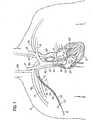
- FIG. 1is a diagrammatic view of an exemplary method of implanting the transseptal cannula assembly in a human heart, shown in cross-section.
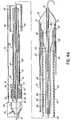
- FIG. 2Ais a disassembled, side elevational view of a delivery apparatus and transseptal cannula assembly.
- FIG. 2Bis an assembled, side elevational view of the delivery apparatus with the transseptal cannula assembly.
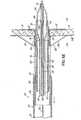
- FIG. 3is a side elevational view of a coaxial balloon catheter, shown in cross-section.
- FIG. 3Ais a cross-sectional view of a coaxial hub of the coaxial balloon catheter, taken along line 3A-3A of FIG. 3 .
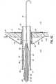
- FIGS. 4A-4Eare side elevational views in partial cross section of an exemplary method of deploying a left atrial anchor of the transseptal cannula assembly.
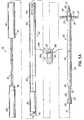
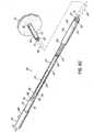
- FIG. 5Ais a disassembled, side elevational view of a right atrial anchor delivery system with the transseptal cannula and the coaxial balloon catheter.
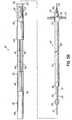
- FIG. 5Bis an assembled, side elevational view of the right atrial anchor delivery system with the transseptal cannula and coaxial balloon catheter.
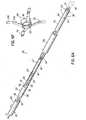
- FIG. 6Ais a perspective view of an exemplary method of assembling the right anchor delivery system and back-loading the right anchor delivery system over the transseptal cannula assembly.
- FIG. 6Bis a side elevation view in partial cross-section of the exemplary method of back-loading the right anchor delivery system over the transseptal cannula assembly.
- FIG. 6Cis a perspective view of an exemplary method of advancing the right anchor delivery system over the transseptal cannula assembly.
- FIG. 6D-6Eare side elevation views in cross section of an exemplary method of deploying the right atrial anchor of the transseptal cannula assembly.
- FIG. 6Fis perspective view of the right atrial anchor.
- FIGS. 6G-6Jare side elevational views in cross section of the exemplary method of completing the implanting of the right atrial anchor of the transseptal cannula assembly.
- FIG. 6Kis a diagrammatic view of an illustrative circulatory assist system positioned in the human heart, shown in cross-section.
- Implanting a circulatory assist devicecan begin with a percutaneous transseptal crossing procedure.
- FIG. 1illustrates a portion of this procedure, where the physician gains access to the heart 10 of the patient 12 from a superior incision site 14.
- a suitable location for the superior incision site 14can be substantially near a superior superficial vein, such as the right or left subclavian veins 15, 16; the right or left jugular veins 17, 18; or the junction between a jugular vein 17, 18 and the corresponding adjoining subclavian vein 15, 16.
- a superior superficial veinsuch as the right or left subclavian veins 15, 16; the right or left jugular veins 17, 18; or the junction between a jugular vein 17, 18 and the corresponding adjoining subclavian vein 15, 16.
- 2009/0112050includes creating a femoral vein access site and directing an anchoring guide-element from the femoral vein access site to the patient's heart 10 and through a heart tissue. A distal portion of the anchoring guide-element is secured to the heart tissue while a proximal portion of the anchoring guide-element is transferred from the femoral vein access site to the superior superficial vein site via a capture device, such as a conventional snare device.
- a capture devicesuch as a conventional snare device.
- Another example not specifically illustrated but also disclosed in U.S. Patent Appl. Ser. No. 2009/0112050includes directing a steerable guidewire from the superior superficial vein site directly to the patient's heart 10. The steerable guidewire then crosses the heart tissue.
- a transseptal cannula 22 with a left anchor delivery system 25are back-loaded over a proximal end of the guidewire 19.
- the transseptal cannula 22is then directed through the right subclavian vein 15, the superior vena cava 23, and into the right atrium 24.
- FIG. 2Aillustrates the details of the left anchor delivery system, which includes a delivery apparatus 26 and a coaxial balloon catheter 28 for aiding in implanting of the transseptal cannula 22.
- the delivery apparatus 26has a proximal hub 32 and a sheath that is configured to receive and move relative to the flexible cannula body.
- the sheathas illustrated, includes a distal sleeve 36 that is connected to the proximal hub 32 by at least one connector member 34.
- the proximal hub 32provides visual and tactile feedback with respect to the deployment of a left atrial anchor 38 (described in detail below) of the transseptal cannula 22.
- the proximal hub 32can be molded as a single polymeric material that is noncompliant, i.e., does not change shape during the physician's use.
- the proximal hub 32 of the delivery apparatus 26may include a docking portion 40 for receiving a proximal end of the coaxial balloon catheter 28.
- the docking portion 40sets a relative position between the coaxial balloon catheter 28 and the delivery apparatus 26 to aid in maintaining the left atrial anchor 38 within the distal sleeve 36 during the implanting procedure.
- the docking portion 40may also aid in minimizing blood loss from between the guidewire 19 and the coaxial balloon catheter 28.
- the at least one connector member 34 of the delivery apparatus 26that couples the distal sleeve 36 to the proximal hub 32 and can be constructed from a rigid polymeric material or a metallic wire. While only one connector member 34 is shown, it would be understood that additional connector members 34 can be used.
- the connector members 34allow the physician to maintain direct control of the transseptal cannula 22 while manipulating the delivery apparatus 26.
- the distal sleeve 36secures the left atrial anchor 38 during the delivery of the transseptal cannula 22 to the intra-atrial septum 20 ( FIG. 1 ).
- the distal sleeve 36can be constructed as single or multiple polymeric layers having lengths sufficient to cover the left atrial anchor 38.
- the sheath of the delivery apparatusextends from the proximal hub and for the length of the transseptal cannula to secure the left atrial anchor 38 during the delivery of the transseptal cannula 22.
- This sheath embodiment of the delivery apparatusis directed over the transseptal cannula 22 and moves relative thereto for deploying the left atrial anchor 38.
- FIG. 2Aillustrates the details of the transseptal cannula 22.
- the transseptal cannula 22is designed such that left and right atrial anchors are implanted and deployed separately. This particular arrangement of the transseptal cannula is able to accommodate greater patient-to-patient variation in intra-atrial septal wall thicknesses and anatomies.
- the transseptal cannulaincludes a flexible cannula body 42 and the distally located left atrial anchor 38.
- the flexible cannula body 42can be constructed of a polymeric material, such as thermoplastic or thermoset.
- a thin-film metallic coatingmay be applied to the polymeric material to inhibit the formation of a thrombosis.
- the flexible cannula body 42may include both a pliable cannula portion 46 and a reinforced cannula portion 48.
- the pliable cannula portion 46allows the flexible cannula body 42 to be secured to a circulatory assist device.
- the reinforced cannula portion 48provides structural stability, increases the ease of manipulating the transseptal cannula 22 through the vascular network, and decreases the likelihood of the flexible cannula body 42 kinking within the vascular network.
- the reinforced cannula portion 48may be constructed by single and/or multi-layer encapsulation of a wire braid or coil; the pliable cannula portion 46 may or may not include the wire braid or coil.
- the left atrial anchor 38includes a tip 50 and at least two opposed struts 51 coupled to the tip 50.
- the tip 50When implanted, the tip 50 will create a shunt through the intra-atrial septum 20 ( FIG. 1 ).
- the overall length of the tip 50can vary according to a particular patient's anatomical needs. Accordingly, in some embodiments, the distal end of the tip 50 could extend as far as 1 cm into the left atrium 21 ( FIG. 1 ); however, in other embodiments, the length of the tip 50 would be flush with the intra-atrial septum 20 ( FIG. 1 ).
- the tip 50can be constructed from a polished metallic, such as titanium (Ti), or from a polymeric material with tungsten (W) embedded for fluoroscopic localization.
- the left atrial anchor 38can, in some embodiments, include a cuff 52 (shown in phantom) to promote tissue in-growth and to further secure the transseptal cannula 22 to the heart tissue.
- the cuffmay be any porous polymeric structure that provides an area for tissue in-growth, and increases the structural stability and sealing capacity as compared to the tip 50 alone. Suitable materials for the cuff 52 may include expanded polytetrafluoroethylene (ePTFE) and DACRON.
- the cuff 52can generally be in at least one of two locations: an inner cuff 52 at the junction between the tip 50 and the flexible cannula body 42; or an outer cuff (not shown) surrounding a joint between the struts 51 and the tip 50.
- the outer cuffcan provide the added benefit of minimizing a galvanic response between the tip 50 and the struts 51.
- the coaxial balloon catheter 28has a coaxial hub 56, a strain relief 58, a tube body 60, and a balloon 62.
- FIG. 3illustrates the coaxial balloon catheter 28 with greater detail.
- the tube body 60has an inner member 64, an outer member 66, and an inflation channel 68 therebetween.
- the inner and outer members 64, 66can be tubular structures extending from the coaxial hub 56 to the balloon 62.
- the inner and outer members 64, 66 of the tube body 60may be formed by an extrusion process from a flexible polymeric material, such as PEBAX or polyurethane.
- the inflation channel 68provides a liquid conduit for an inflation fluid, such as saline or a contrast medium, to travel between the coaxial hub 56 and the balloon 62.
- the proximal end of the inner member 64is coupled to the coaxial hub 56 while the distal end of the inner member 64 extends through the balloon 62 and is coupled at the distal end of the balloon 62.
- the inner member 64includes a lumen 70 that is substantially similar in diameter to the diameter of the guidewire 19 ( FIG. 2A ).
- the inner member 64can also include at least one distally located marker 69 constructed from a metallic material, such as gold (Au) or platinum (Pt) or from a polymeric material embedded with a dense powder, such as tungsten (W).
- the marker 69aids the physician in positioning the transseptal cannula 22 in vivo and in a manner that is described in detail below.
- the more distal marker bandcan be used to position the left atrial anchor 38 ( FIG. 2A ) within the left atrium 21 ( FIG. 1 ) while the more proximal marker band can be used to position the right atrial anchor (discussed below) within the right atrium 24 ( FIG. 1 ).
- the proximal end of the outer member 66 of the coaxial balloon catheter 28is coupled to the coaxial hub 56 while the distal end of the outer member 66 is coupled to the proximal end of the balloon 62.
- the hub-inner member bond 71may be positioned proximal to the hub-outer member bond 72 to improve lumen inflation patency.
- a chemical bond (UV adhesive) or energy transfer process (thermal melting or RF)can be used to couple the inner and outer member 64, 66 to the coaxial hub 56.
- FIGS. 3 and 3Aillustrate the coaxial hub 56 of the coaxial balloon catheter 28.
- the coaxial hub 56is constructed to have a low profile, such as a cylindrical or other straight or continuous outer profile, that would allow other hollow or tubular surgical devices to be directed over the coaxial hub 56 without deflating and removing the balloon 62. This is unlike a typical Y-shaped hub, for example, that would not allow such a function.
- the coaxial hub 56has a hub-body 74, a hub-cap 75, a plurality of spokes 76, and a grommet 78.
- the hub-body 74 and hub-cap 75form the main body of the coaxial hub 56.
- the plurality of spokes 76are integrally molded within the hub-body 74, provide a positive stop for the grommet 78, and define a fluid space 79 that is in fluidic communication with the inflation channel 68.
- the plurality of spokes 76can also provide a surface for coupling the inner member 64 to the coaxial hub 56.
- the grommet 78provides a fluid-tight seal for holding a desired liquid pressure within the balloon 62 while permitting a syringe needle, or other similar solid object, to puncture and pass to the fluid space 79.
- the grommet 78can be self-healing, i.e., maintains the fluid seal after the syringe needle has been removed.
- the hub-cap 75can include a grommet retention feature 80 to prevent migration of the grommet 78 from the coaxial hub 56 after assembly.
- the hub-body 74 and hub-cap 75 of the coaxial hub 56can be molded from the same, or different, rigid materials that will resist compression. Suitable materials may include nylon or polycarbonate.
- the grommet 78is formed by a molding process of an elastomeric material, such as polyurethane or silicone (Si). Once the grommet 78 is positioned within the hub-cap 75, the hub-cap 75 and hub-body 74 are bonded using chemical bonding (UV adhesives) or an energy transfer process (thermal melting or RF).
- the strain relief 58can be bonded to the coaxial hub 56 by interference fit or by chemical bond.
- the strain relief 58strengthens the connection between the rigid coaxial hub 56 and the more flexible tube body 60 and provides a transition that aids in kink resistance at this location.
- the balloon 62can be constructed from a compliant polymeric material (lower durometer) for easy inflation or from a noncompliant polymeric material (higher durometer) that will resist change with increases in fluidic pressure.
- Suitable compliant materialscan include PEBAX or polyurethane while noncompliant materials can include nylon or polyethylene terephthalate (PET).
- PETpolyethylene terephthalate
- the balloon materialis shaped to a cylindrical shape by a thermoforming process and is then bonded to the inner and outer members 64, 66 by either an energy transfer process (thermal melting or RF) or a chemical bonding (UV adhesive).
- the walls of the balloon 62 and the inner member 64create an annular cavity 86 in fluid communication with the inflation channel 68 of the tube body 60.
- the fully inflated balloon 62can withhold liquid pressures up to approximately 12 atm.
- the at least partially inflated balloon 62will include a distal cone structure 82 that can facilitate the dilation of an opening through the intra-atrial septum 20 ( FIG. 1 ) in a manner described below.
- the proximal end 84 of the balloon 62should include sufficient surface area for coupling the balloon 62 to the outer member 66 by an energy transfer process or chemical bonding.
- the physicianinserts a syringe needle of a syringe containing the inflation fluid through the grommet 78 of the coaxial hub 56 and into the fluid space 79.
- the inflation fluidis transferred from the syringe to the fluid space 79, the inflation channel 68, and into the annular cavity 86 of the balloon 62 where it will increase the fluid pressure and cause the walls of the balloon 62 to expand.
- FIG. 4Aillustrates the delivery apparatus 26, the transseptal cannula 22, and the coaxial balloon catheter 28 coaxially loaded over the guidewire 19.
- the balloon 62is positioned within the lumen of the tip 50 such that the marker 69 is approximately aligned with the distal end of the tip 50. Then, as the balloon 62 is inflated with the inflation fluid, the balloon 62 contacts the inner diameter of the tip 50. This contact between the tip 50 and the balloon 62 allows the physician to advance the transseptal cannula 22 and the coaxial balloon catheter 28 as a unit over the guidewire 19.
- the balloon 62can be further inflated to contact the inner diameter of the distal sleeve 36 of the delivery apparatus 26.
- This contact between the distal sleeve 36 and the balloon 62would further allow the physician to advance the transseptal cannula 22, the coaxial balloon catheter 28, and the delivery apparatus 26 as a unit over the guidewire 19.
- the relative positions of the coaxial balloon catheter 28 and the delivery apparatus 26can further be aided by positioning the coaxial hub 56 of the coaxial balloon catheter 28 within the docking portion 40 of the delivery apparatus 26.
- FIG. 4Billustrates the delivery apparatus 26, the transseptal cannula 22, and the coaxial balloon catheter 28 within the right atrium 24 and advanced to the intra-atrial septum 20.
- the delivery apparatus 26 with the coaxial balloon catheter 28 and the transseptal cannula 22are shown advancing, as a unit, through the intra-atrial septum 20 and into the left atrium 21.
- the distal cone structure 82contacts and dilates the opening 87 through the intra-atrial septum 20 that was created previously by the guidewire 19.
- the opening 87is sufficiently dilated so that the distal sleeve 36 may also easily enter the left atrium 21.
- FIG. 4Dillustrates one method of deploying the struts 51 of the left atrial anchor 38 within the left atrium 21 from a contracted state (shown in phantom) to an expanded state (shown in solid).
- Struts 51 in the expanded stateare transverse to a lengthwise central axis of the flexible cannula body 42 and will resist movement of the transseptal cannula 22 in at least one direction along the lengthwise central axis.
- the struts 51can be machined from a tubular structure, formed from wire, or formed from a flat sheet stock, which may be any superelastic, shape-memory material, such as nickel titanium (NiTi) or MP35N.
- the struts 51remain bare; however, it is possible to include a porous polymeric structure, such as a coating of calcium phosphate (Ca 3 (PO 4 ) 2 ), collagen, or a porous polymeric fabric to promote tissue in-growth and further secure the tip 50 to the heart tissue.
- a porous polymeric structuresuch as a coating of calcium phosphate (Ca 3 (PO 4 ) 2 ), collagen, or a porous polymeric fabric to promote tissue in-growth and further secure the tip 50 to the heart tissue.
- Deploying the left atrial anchor 38begins with the physician confirming that the tip 50 and the struts 51 are through the intra-atrial septum 20 and within the left atrium 21.
- the confirmationcan be accomplished by in vivo localization of the marker 69 with X-ray, real-time fluoroscopy, or intracardiac echocardiograph.
- the balloon 62is at least partially deflated to remove the contact between the distal sleeve 36 and the balloon 62 such that the distal sleeve 36 moves with respect to the transseptal cannula 22 and the coaxial balloon catheter 28. However, the balloon 62 remains sufficiently inflated to maintain the contact between the tip 50 and the balloon 62.
- the coaxial balloon catheter 28 and the tip 50are advanced, as a unit, further into the left atrium 21 while the distal sleeve 36 is held in position.
- the left atrial anchor 38extends beyond the distal sleeve 36 of the delivery apparatus 26 and is deployed within the volume of the left atrium 21.
- the delivery apparatus 26is then retracted from the left atrium 21, the intra-atrial septum 20, and the right atrium 24.
- struts 51may have a diameter that is at least 1.1 times, but smaller than about 3 times, the diameter of the orifice created by the tip 50 through the intra-atrial septum 20; however, the diameter of the struts 51 in the expanded state is limited primarily by the patient's anatomy.
- the distal tip 50can extend about 3mm from the deployed left atrial anchor 38.
- the physiciancan ensure proper deployment of the struts 51 by in vivo visualization of a radiopaque marker (not shown) on the struts 51.
- a radiopaque marker(not shown) on the struts 51.
- a right atrial anchor 88can be implanted, which will now be described in detail with reference to FIGS. 5A-5B .
- FIG. 5Aillustrates the details of the right atrial anchor 88 and a right atrial anchor delivery system 89.
- the right atrial anchor 88has at least two opposed struts 94 coupled to a tip 96, where the struts 94 are operable to move from a contracted state (shown in solid) to an extended state (shown in phantom).
- the struts 94may be machined from a tubular structure formed using wire or formed from a flat sheet stock, as was described in U.S. Patent Appl. Ser. No. 2009/0112050 .
- the wire or flat sheet stockmay be any shape-memory material (such as nickel titanium, NiTi, or MP35N).
- the shape shownincludes an angled portion 94a and a contact portion 94b in the extended state.
- the contact portion 94bwill contact the intra-atrial septum 20 ( FIG. 1 ).
- the angled portion 94aallows the right atrial anchor 88 to accommodate a wide range of anatomies and septal wall thicknesses.
- the angled portion 94aalso creates a force that will resist a distal movement of the transseptal cannula 22 once the right atrial anchor 88 is properly attached to the left atrial anchor 38 and implanted in the intra-atrial septum 20 ( FIG. 1 ).
- the tip 96can be constructed in a manner that is similar to that described previously with respect to the tip 50 of the left atrial anchor 38.
- the right atrial anchor 88can include an anchor cuff 97 (shown in phantom) to promote localized tissue growth.
- the anchor cuff 97can be a porous polymeric structure constructed from an implantable porous material (e.g., ePTFE, DACRON) as an inner cuff (not shown) and/or an outer cuff 97 similar to that described previously with the left atrial anchor 38.
- the right atrial anchor 88may include a full disc (not shown) surrounding all of the struts 94.
- the full disccan also be constructed from an implantable porous material (e.g., ePTFE, DACRON). While a separate full disc (not shown) could also surround all of the struts 51 of the left atrial anchor 38, the configuration surrounding the struts 94 of the right atrial anchor 88 is preferred because the right atrium 24 is larger in volume than the left atrium 21.
- an implantable porous materiale.g., ePTFE, DACRON
- FIG. 5Afurther illustrates the right anchor delivery apparatus 92 used to deliver the right atrial anchor 88 to the intra-atrial septum 20 ( FIG. 1 ).
- the right anchor delivery apparatus 92has a proximal hub 98 and a distal sleeve 100 connected to the proximal hub 98 by at least one connector member 102 (two connector members 102 are shown).
- the proximal hub 98which can be molded from a single polymeric material, provides visual and tactile feedback to the physician throughout the surgical procedure.
- the connector members 102are made of a single polymeric or metallic material and should be constructed with a low profile. The low profile allows the physician to maintain greater control over the transseptal cannula 22 while manipulating the right anchor delivery apparatus 92.
- the distal sleeve 100holds the right atrial anchor 88 during delivery to the transseptal cannula 22 and the intra-atrial septum 20 ( FIG. 1 ).
- the distal sleeve 100includes notches 104 into which the struts 94 of the right atrial anchor 88 rest.
- the notches 104also contribute to an over-all low-profile assembly.
- the number of notches 104should equal the number of struts 94 of the right atrial anchor 88.
- FIG. 5Aalso illustrates the right anchor sheath 90.
- the right anchor sheath 90includes a distal sleeve 106 and a proximal hub 108 and sheath body configured to receive and move relative to the right anchor delivery apparatus 92.
- the sheath bodyincludes a distal sleeve 106 that is connected to the proximal hub 108 by at least one connector member 110 (two connector members are shown).
- the distal sleeve 106secures the struts 94 of the right atrial anchor 88 in a contracted state.
- the distal sleeve 106may be constructed from single polymeric or multiple polymeric layers. The length of the distal sleeve 106 should cover the length of the struts 94 in the contracted state.
- the proximal hub 108provides the physician with visual and tactile feedback when the distal sleeve 106 is moved relative to the transseptal cannula 22.
- the proximal hub 108is typically molded from a single polymeric material and has sufficient rigidity so as to not be damaged or deformed during normal handling by the physician.
- the connector members 110are constructed from a rigid polymeric material or metallic structure, such as a wire, and surround the transseptal cannula 22. This arrangement creates a low profile and allows the physician to maintain direct control of the transseptal cannula 22 while manipulating the distal sleeve 106.
- the right anchor sheath 90may alternatively include a sheath extending from the proximal hub and for the length of the right anchor delivery apparatus 92. The sheath is directed over the right anchor delivery apparatus 92 and secures the right atrial anchor 88 until deployment.
- FIG. 5Billustrates the assembled right anchor delivery system 89, including the right anchor sheath 90 and the right anchor delivery apparatus 92 with the right atrial anchor 88.
- the right anchor delivery system 89is back-loaded over the guidewire 19, the coaxial balloon catheter 28, and the transseptal cannula 22.
- the method of implanting the right atrial anchor 88can continue with reference to FIGS. 6A-6J .
- FIGS. 6A-6Billustrate the method of assembling the right anchor delivery system 89, and the loading of the right anchor delivery system 89 over the coaxial balloon catheter 28 and the transseptal cannula 22.
- the proximal hubs 108, 98may each include an alignment member 114, 116, respectively.
- the alignment members 114, 116maintain a radial alignment between the right anchor delivery apparatus 92 and the right anchor sheath 90 during the delivery of the right atrial anchor 88.
- the alignment members 114, 116can be molded as a portion of the respective proximal hubs 108, 98.
- the alignment members 114, 116have similar perimeter shape; however, the alignment member 114 is formed as a negative image of the alignment member 116. This structure allows the alignment member 114, 116 to mate and resist rotational movement.
- the particular shapes and arrangements shownshould not be considered limiting.
- FIG. 6Cillustrates the assembled right anchor delivery apparatus 92 and the loading of the right anchor delivery apparatus 92 and the right anchor sheath 90, as a unit, over the right anchor delivery system 89 to the intra-atrial septum 20.
- FIG. 6Dillustrates the right atrial anchor 88 positioned at the intra-atrial septum 20.
- the right atrial anchor 88may now be attached to the tip 50 by way of a mechanical connection, such as a friction or interference fit, a magnet, or a screw thread.
- the struts 94are then deployed, as described below.
- FIG. 6Eillustrates the right anchor delivery apparatus 92 positioned against the intra-atrial septum 20 as the distal sleeve 106 is retracted. After sufficient retraction, the struts 94 are released to automatically deploy from the contracted state (shown in solid in FIG. 6D ) to a deployed state (shown in solid) against the intra-atrial septum 20.
- FIG. 6Fillustrates the right atrial anchor 88 having at least one locking member 118 on the inner diameter of the tip 96.
- the at least one locking member 118provides one manner of attaching and securing the tip 96 of the right atrial anchor 88 to the tip 50 ( FIG. 6E ) of the left atrial anchor 38 ( FIG. 6E ).
- the locking members 118can include any manner of creating and maintaining a compression fit between the tip 96 of the right atrial anchor 88 and the tip 50 of the left atrial anchor 38.
- FIG. 6Gillustrates the retraction of the right anchor delivery apparatus 92 once the tip 96 of the right atrial anchor 88 is secured and the struts 94 are deployed.
- FIG. 6Hthen illustrates the deflating of the coaxial balloon catheter 28.
- the syringe needle 124 of the syringeis inserted through the grommet 78 and into the fluid space 79 of the coaxial hub 56.
- the inflation fluidis then withdrawn through the lumen 126 of the syringe needle 124 and into the syringe, which will decrease the fluid pressure within the balloon 62 and cause deflation.
- the balloon 62is released from its contact with the inner surface of the tip 50 and can be retracted.
- the coaxial balloon catheter 28is then retracted, followed by the guidewire 19 shown in FIG. 6J .
- a hemostasis cuff(not shown) where the proximal end of the transseptal cannula 22 meets the incision into the right subclavian vein 15 and before attaching the transseptal cannula 22 to the pump of the circulatory assist device, and as disclosed in U.S. Patent Appl. Ser. No. 2009/0112050 .
- the hemostasis cuffseals the incision into the right subclavian vein 15 and may provide further resistance to movement of the transseptal cannula 22.
- FIG. 6Killustrates the implanted circulatory assist system.
- the transseptal cannula 22, which extends from the right and left atrial anchors 88, 38 to the superior incision site 14is attached to an inflow port 128 of an implantable pump 130 of the circulatory assist device.
- An outflow cannula 132is coupled to the outflow port 134 of the pump 130.
- the opposing end of the outflow cannula 132is surgically attached as so to communicate with a suitable superficial artery, such as the right subclavian artery 136.
- the physicianmay position the pump 130 subcutaneously or submuscularly within the superior incision site 14 or maintain the pump 130 externally even after the superior incision site 14 is closed.
- the pump 130can be operably associated with a controller (not shown), which may also be implanted or remain external to the patient 12.
- a signal transmission means(not shown) is provided between the pump 130 and the controller and may be either a hard-wired or wireless communications device.
- the controllermay regulate the pumping action of the pump 130.
- a memory device(not shown) may be included within the controller that will record pump activity for subsequent doctor evaluation and interaction.
- oxygenated bloodwill exit the left atrium 21 via the natural path, into the left ventricle 138, to the aorta 140. From the aorta 140, blood moves into the left subclavian artery 142, the left common carotid artery 144, and the brachiocephalic trunk 146, which supplies oxygenated blood to the right common carotid 148 and the right subclavian artery 136. Oxygenated blood will also enter the transseptal cannula 22 from the left atrium 21. Blood entering the flexible cannula body 42 of the transseptal cannula 22 will travel through the lumen of the flexible cannula body 42 to the pump 130. The pump 130 actively pumps blood into the outflow cannula 132 and into the right subclavian artery 136. From here, the blood is directed into the remainder of the vascular network.
Landscapes
- Health & Medical Sciences (AREA)
- Heart & Thoracic Surgery (AREA)
- Life Sciences & Earth Sciences (AREA)
- Engineering & Computer Science (AREA)
- Public Health (AREA)
- Veterinary Medicine (AREA)
- Hematology (AREA)
- Anesthesiology (AREA)
- Animal Behavior & Ethology (AREA)
- General Health & Medical Sciences (AREA)
- Biomedical Technology (AREA)
- Pulmonology (AREA)
- Biophysics (AREA)
- Vascular Medicine (AREA)
- Cardiology (AREA)
- Mechanical Engineering (AREA)
- Child & Adolescent Psychology (AREA)
- Otolaryngology (AREA)
- Surgical Instruments (AREA)
- Media Introduction/Drainage Providing Device (AREA)
- External Artificial Organs (AREA)
- Prostheses (AREA)
Description
- Circulatory assist devices were developed over a decade ago and provide assistance to a diseased heart by way of a meahanical pump. In this way, the circulation of blood through the vascular network is aided despite the presence of diseased tissue. Traditionally, these circulatory assist devices Included an implantable pump, a controller (internal or external), and inflow and outflow tubes connecting the pump to the vascular network. The FDA has approved circulatory assist devices to partially relieve the symptoms of breathlessness and fatigue that are associated with severe heart failure and can drastically improve a patient's quality of life.
- The surgical process associated with the circulatory assist device is highly invasive. At the very least, the procedure involves a thoracotomy, i.e., the opening of the thoracle cavity between successive ribs to expose the internal organe. More typical is cardiac surgery, generally known as open-heart surgery, where the stemum is cut and split to expose the internal organs. Once the thoracic cavity is acceesed, the physician must enter the pleural space and puncture both the pericardium and the myocardial wall. There are great risks and an extensive recovery time associated with the implantation surgery. As such, the patients with severe symptoms are not healthy enough for the surgical procedure.
- A transseptal cannula is described in
U. S. Patent Appl. Ser. No. 2009/0112050 . The transseptal cannula described therein provides greater accessibility to the circulatory assist device by minimizing the invasiveness of the implantation surgery for those patients that would gain the most benefit while awaiting a heart transplant. - There continues to be a need to implement additional features that would facilitate the delivery of the transseptal cannula and/or that would allow the physician to maintain control over the transseptal cannula device during the surgical procedure.
US 5338301 discloses an extendable balloon-on-a-wire catheter which includes a telescoping exchange core wire mounted along the inside lumen of the longitudinal tube of the balloon-on-a-wire assembly. In the preferred embodiment, the exchange core wire is mounted within a hypodermic tube secured to the core wire of the balloon-on-a-wire assembly. A multiple component system includes this balloon-on-a-wire assembly together with an over-the-wire catheter which slidably passes over the elongated body of the balloon-on-a-wire assembly.EP 0213 748 discloses a dual dilatation catheter with two tubular elements defining a lumen therebetween. A balloon is carried by the outer element and a guidewire can be passed through the inner element.- In one aspect, a coaxial balloon catheter is provided and includes a tube body, a coaxial hub, and a balloon. The tube body includes an inner member and outer member surrounding the inner-member and thereby creating an inflation channel between the inner and outer members. The hub is coupled in a coaxial manner to the proximal portion of the tube body and includes a fluid space in fluid communication with the inflation channel. The coaxial hub has an outer surface configured to receive a tubular surgical device thereover. The balloon is coupled to a distal portion of the tube body and a distal portion of the inner member extends through the balloon thereby creating an annular cavity between a wall of the balloon and the inner member.
- The coaxial hub includes a hub-body coupled to a hub-cap and enclosing a grommet. The grommet may be operable to retain an inflation fluid within the annular cavity of the balloon. The grommet may permit a rigid element such as a needle or a syllet to enter the inflation channel. The hub-cap may include a grommet retention feature operable to prevent migration of the grommet. The coaxial hub may include a plurality of spokes operable to couple the inner member to the coaxial hub and/or to provide a positive atop for the grommet.
- A transseptal cannula assembly is also provided in another aspect and includes a flexible cannula body, a left atrial anchor, and a right atrial anchor. The flexible cannula body includes distal and proximal ends with a lumen extending therebetween. The left atrial anchor Is coupled to the distal end of the flexible cannula body and is configured to be deployed from a contracted state to an expanded state to engage at least one side of heart tissue is the expanded state. The right atrial anchor is attachable to the left atrial anchorin vivo and is configured to be deployed from a contracted state to an expanded state to engage an opposing side of the heart tissue in expanded state. The assembly may include struts made of a superelastic material which is a tubular structure, a wire, or a flat sheet stock.
- The transseptal cannula may be used in combination with a left anchor delivery system including a sheath and a proximal hub. The sheath may be a distal sleeve that receives the left atrial anchor and is connected to the proximal hub by at least one connector member. The sheath may extend distally from the proximal hub and secures the left atrial anchor.
- The transseptal cannula assembly may also be used in combination with a right anchor delivery system. The right anchor delivery system comprises a right anchor delivery apparatus configured to engage the left atrial anchor and couple the right atrial anchor to the left atrial anchor. A right anchor sheath includes a proximal hub and a sheath body configured to receive the right anchor delivery apparatus and move relative thereto for deploying the right atrial anchor into the expanded state.
- The right anchor delivery apparatus may include a proximal hub and a distal sleeve connected to the proximal hub by at least one connector member, the distal sleeve configured to engage the right atrial anchor. The distal sleeve may include notches for receiving the at least two opposed struts of the right atrial anchor. The sheath body of the right anchor sheath may be a distal sleeve that receives the right atrial anchor and is connected to the proximal hub by at least one connector member. The sheath body may extend distally from the proximal hub and receives the right atrial anchor.
- Methods of delivering a transseptal cannula assembly to a heart tissue are also disclosed.
- The invention will now be further described by way of example with reference to the accompanying drawings, in which:
FIG. 1 is a diagrammatic view of an exemplary method of implanting the transseptal cannula assembly in a human heart, shown in cross-section.FIG. 2A is a disassembled, side elevational view of a delivery apparatus and transseptal cannula assembly.FIG. 2B is an assembled, side elevational view of the delivery apparatus with the transseptal cannula assembly.FIG. 3 is a side elevational view of a coaxial balloon catheter, shown in cross-section.FIG. 3A is a cross-sectional view of a coaxial hub of the coaxial balloon catheter, taken alongline 3A-3A ofFIG. 3 .FIGS. 4A-4E are side elevational views in partial cross section of an exemplary method of deploying a left atrial anchor of the transseptal cannula assembly.FIG. 5A is a disassembled, side elevational view of a right atrial anchor delivery system with the transseptal cannula and the coaxial balloon catheter.FIG. 5B is an assembled, side elevational view of the right atrial anchor delivery system with the transseptal cannula and coaxial balloon catheter.FIG. 6A is a perspective view of an exemplary method of assembling the right anchor delivery system and back-loading the right anchor delivery system over the transseptal cannula assembly.FIG. 6B is a side elevation view in partial cross-section of the exemplary method of back-loading the right anchor delivery system over the transseptal cannula assembly.FIG. 6C is a perspective view of an exemplary method of advancing the right anchor delivery system over the transseptal cannula assembly.FIG. 6D-6E are side elevation views in cross section of an exemplary method of deploying the right atrial anchor of the transseptal cannula assembly.FIG. 6F is perspective view of the right atrial anchor.FIGS. 6G-6J are side elevational views in cross section of the exemplary method of completing the implanting of the right atrial anchor of the transseptal cannula assembly.FIG. 6K is a diagrammatic view of an illustrative circulatory assist system positioned in the human heart, shown in cross-section.- Implanting a circulatory assist device according to one embodiment can begin with a percutaneous transseptal crossing procedure.
FIG. 1 illustrates a portion of this procedure, where the physician gains access to theheart 10 of the patient 12 from asuperior incision site 14. A suitable location for thesuperior incision site 14 can be substantially near a superior superficial vein, such as the right or leftsubclavian veins jugular veins jugular vein subclavian vein heart 10. One example not specifically illustrated here, but disclosed inU.S. Patent Appl. Ser. No. 2009/0112050 includes creating a femoral vein access site and directing an anchoring guide-element from the femoral vein access site to the patient'sheart 10 and through a heart tissue. A distal portion of the anchoring guide-element is secured to the heart tissue while a proximal portion of the anchoring guide-element is transferred from the femoral vein access site to the superior superficial vein site via a capture device, such as a conventional snare device. Another example not specifically illustrated but also disclosed inU.S. Patent Appl. Ser. No. 2009/0112050 includes directing a steerable guidewire from the superior superficial vein site directly to the patient'sheart 10. The steerable guidewire then crosses the heart tissue. - Referring still to
FIG. 1 , once the guidewire 19 (or anchoring guide-element) traverses the heart tissue, such as theintra-atrial septum 20, and enters theleft atrium 21, atransseptal cannula 22 with a leftanchor delivery system 25 are back-loaded over a proximal end of theguidewire 19. Thetransseptal cannula 22 is then directed through the rightsubclavian vein 15, thesuperior vena cava 23, and into theright atrium 24. FIG. 2A illustrates the details of the left anchor delivery system, which includes adelivery apparatus 26 and acoaxial balloon catheter 28 for aiding in implanting of thetransseptal cannula 22. Thedelivery apparatus 26 has aproximal hub 32 and a sheath that is configured to receive and move relative to the flexible cannula body. The sheath, as illustrated, includes adistal sleeve 36 that is connected to theproximal hub 32 by at least oneconnector member 34. Theproximal hub 32 provides visual and tactile feedback with respect to the deployment of a left atrial anchor 38 (described in detail below) of thetransseptal cannula 22. Theproximal hub 32 can be molded as a single polymeric material that is noncompliant, i.e., does not change shape during the physician's use. Theproximal hub 32 of thedelivery apparatus 26 may include adocking portion 40 for receiving a proximal end of thecoaxial balloon catheter 28. Thedocking portion 40 sets a relative position between thecoaxial balloon catheter 28 and thedelivery apparatus 26 to aid in maintaining the leftatrial anchor 38 within thedistal sleeve 36 during the implanting procedure. Thedocking portion 40 may also aid in minimizing blood loss from between theguidewire 19 and thecoaxial balloon catheter 28.- The at least one
connector member 34 of thedelivery apparatus 26 that couples thedistal sleeve 36 to theproximal hub 32 and can be constructed from a rigid polymeric material or a metallic wire. While only oneconnector member 34 is shown, it would be understood thatadditional connector members 34 can be used. Theconnector members 34 allow the physician to maintain direct control of thetransseptal cannula 22 while manipulating thedelivery apparatus 26. - The
distal sleeve 36 secures the leftatrial anchor 38 during the delivery of thetransseptal cannula 22 to the intra-atrial septum 20 (FIG. 1 ). Thedistal sleeve 36 can be constructed as single or multiple polymeric layers having lengths sufficient to cover the leftatrial anchor 38. - In another embodiment not specifically illustrated, the sheath of the delivery apparatus extends from the proximal hub and for the length of the transseptal cannula to secure the left
atrial anchor 38 during the delivery of thetransseptal cannula 22. This sheath embodiment of the delivery apparatus is directed over thetransseptal cannula 22 and moves relative thereto for deploying the leftatrial anchor 38. FIG. 2A illustrates the details of thetransseptal cannula 22. Thetransseptal cannula 22 is designed such that left and right atrial anchors are implanted and deployed separately. This particular arrangement of the transseptal cannula is able to accommodate greater patient-to-patient variation in intra-atrial septal wall thicknesses and anatomies. The transseptal cannula includes aflexible cannula body 42 and the distally located leftatrial anchor 38. Theflexible cannula body 42 can be constructed of a polymeric material, such as thermoplastic or thermoset. A thin-film metallic coating may be applied to the polymeric material to inhibit the formation of a thrombosis. Other coatings can also be applied, such as with polyethylene terephthalate glycol (PETG) for lubricating theflexible cannula body 42. Theflexible cannula body 42 may include both apliable cannula portion 46 and a reinforcedcannula portion 48. Thepliable cannula portion 46 allows theflexible cannula body 42 to be secured to a circulatory assist device. The reinforcedcannula portion 48 provides structural stability, increases the ease of manipulating thetransseptal cannula 22 through the vascular network, and decreases the likelihood of theflexible cannula body 42 kinking within the vascular network. The reinforcedcannula portion 48 may be constructed by single and/or multi-layer encapsulation of a wire braid or coil; thepliable cannula portion 46 may or may not include the wire braid or coil.- The left
atrial anchor 38 includes atip 50 and at least twoopposed struts 51 coupled to thetip 50. When implanted, thetip 50 will create a shunt through the intra-atrial septum 20 (FIG. 1 ). The overall length of thetip 50 can vary according to a particular patient's anatomical needs. Accordingly, in some embodiments, the distal end of thetip 50 could extend as far as 1 cm into the left atrium 21 (FIG. 1 ); however, in other embodiments, the length of thetip 50 would be flush with the intra-atrial septum 20 (FIG. 1 ). Thetip 50 can be constructed from a polished metallic, such as titanium (Ti), or from a polymeric material with tungsten (W) embedded for fluoroscopic localization. - The left
atrial anchor 38 can, in some embodiments, include a cuff 52 (shown in phantom) to promote tissue in-growth and to further secure thetransseptal cannula 22 to the heart tissue. The cuff may be any porous polymeric structure that provides an area for tissue in-growth, and increases the structural stability and sealing capacity as compared to thetip 50 alone. Suitable materials for the cuff 52 may include expanded polytetrafluoroethylene (ePTFE) and DACRON. The cuff 52 can generally be in at least one of two locations: an inner cuff 52 at the junction between thetip 50 and theflexible cannula body 42; or an outer cuff (not shown) surrounding a joint between thestruts 51 and thetip 50. The outer cuff can provide the added benefit of minimizing a galvanic response between thetip 50 and thestruts 51. - Referring still to
FIG. 2A , but also to the assembled view inFIG. 2B , thedelivery apparatus 26 and thetransseptal cannula 22 are shown to coaxially surround thecoaxial balloon catheter 28. Thecoaxial balloon catheter 28 has acoaxial hub 56, astrain relief 58, atube body 60, and aballoon 62. FIG. 3 illustrates thecoaxial balloon catheter 28 with greater detail. Thetube body 60 has aninner member 64, anouter member 66, and aninflation channel 68 therebetween. The inner andouter members coaxial hub 56 to theballoon 62. The inner andouter members tube body 60 may be formed by an extrusion process from a flexible polymeric material, such as PEBAX or polyurethane. Theinflation channel 68 provides a liquid conduit for an inflation fluid, such as saline or a contrast medium, to travel between thecoaxial hub 56 and theballoon 62.- The proximal end of the
inner member 64 is coupled to thecoaxial hub 56 while the distal end of theinner member 64 extends through theballoon 62 and is coupled at the distal end of theballoon 62. Theinner member 64 includes alumen 70 that is substantially similar in diameter to the diameter of the guidewire 19 (FIG. 2A ). Theinner member 64 can also include at least one distally locatedmarker 69 constructed from a metallic material, such as gold (Au) or platinum (Pt) or from a polymeric material embedded with a dense powder, such as tungsten (W). Themarker 69 aids the physician in positioning thetransseptal cannula 22in vivo and in a manner that is described in detail below. Though not shown, if two or more marker bands are used, then the more distal marker band can be used to position the left atrial anchor 38 (FIG. 2A ) within the left atrium 21 (FIG. 1 ) while the more proximal marker band can be used to position the right atrial anchor (discussed below) within the right atrium 24 (FIG. 1 ). - The proximal end of the
outer member 66 of thecoaxial balloon catheter 28 is coupled to thecoaxial hub 56 while the distal end of theouter member 66 is coupled to the proximal end of theballoon 62. The hub-inner member bond 71 may be positioned proximal to the hub-outer member bond 72 to improve lumen inflation patency. A chemical bond (UV adhesive) or energy transfer process (thermal melting or RF) can be used to couple the inner andouter member coaxial hub 56. FIGS. 3 and 3A illustrate thecoaxial hub 56 of thecoaxial balloon catheter 28. Thecoaxial hub 56 is constructed to have a low profile, such as a cylindrical or other straight or continuous outer profile, that would allow other hollow or tubular surgical devices to be directed over thecoaxial hub 56 without deflating and removing theballoon 62. This is unlike a typical Y-shaped hub, for example, that would not allow such a function. Thecoaxial hub 56 has a hub-body 74, a hub-cap 75, a plurality ofspokes 76, and agrommet 78. The hub-body 74 and hub-cap 75 form the main body of thecoaxial hub 56. The plurality ofspokes 76 are integrally molded within the hub-body 74, provide a positive stop for thegrommet 78, and define afluid space 79 that is in fluidic communication with theinflation channel 68. The plurality ofspokes 76 can also provide a surface for coupling theinner member 64 to thecoaxial hub 56. Thegrommet 78 provides a fluid-tight seal for holding a desired liquid pressure within theballoon 62 while permitting a syringe needle, or other similar solid object, to puncture and pass to thefluid space 79. Thegrommet 78 can be self-healing, i.e., maintains the fluid seal after the syringe needle has been removed. The hub-cap 75 can include agrommet retention feature 80 to prevent migration of thegrommet 78 from thecoaxial hub 56 after assembly.- The hub-
body 74 and hub-cap 75 of thecoaxial hub 56 can be molded from the same, or different, rigid materials that will resist compression. Suitable materials may include nylon or polycarbonate. Thegrommet 78 is formed by a molding process of an elastomeric material, such as polyurethane or silicone (Si). Once thegrommet 78 is positioned within the hub-cap 75, the hub-cap 75 and hub-body 74 are bonded using chemical bonding (UV adhesives) or an energy transfer process (thermal melting or RF). - The
strain relief 58 can be bonded to thecoaxial hub 56 by interference fit or by chemical bond. Thestrain relief 58 strengthens the connection between the rigidcoaxial hub 56 and the moreflexible tube body 60 and provides a transition that aids in kink resistance at this location. - Continuing with
FIG. 3 , theballoon 62 can be constructed from a compliant polymeric material (lower durometer) for easy inflation or from a noncompliant polymeric material (higher durometer) that will resist change with increases in fluidic pressure. Suitable compliant materials can include PEBAX or polyurethane while noncompliant materials can include nylon or polyethylene terephthalate (PET). The balloon material is shaped to a cylindrical shape by a thermoforming process and is then bonded to the inner andouter members balloon 62 and theinner member 64 create anannular cavity 86 in fluid communication with theinflation channel 68 of thetube body 60. The fully inflatedballoon 62 can withhold liquid pressures up to approximately 12 atm. The at least partiallyinflated balloon 62 will include adistal cone structure 82 that can facilitate the dilation of an opening through the intra-atrial septum 20 (FIG. 1 ) in a manner described below. Theproximal end 84 of theballoon 62 should include sufficient surface area for coupling theballoon 62 to theouter member 66 by an energy transfer process or chemical bonding. - To inflate the
balloon 62, the physician inserts a syringe needle of a syringe containing the inflation fluid through thegrommet 78 of thecoaxial hub 56 and into thefluid space 79. The inflation fluid is transferred from the syringe to thefluid space 79, theinflation channel 68, and into theannular cavity 86 of theballoon 62 where it will increase the fluid pressure and cause the walls of theballoon 62 to expand. - With the details of the left anchor delivery system 25 (
FIG. 2A ) and thetransseptal cannula 22 described with some detail, the method of implanting thetransseptal cannula 22 with the leftatrial anchor 38 can continue with reference toFIGS. 4A -4F.FIG. 4A illustrates thedelivery apparatus 26, thetransseptal cannula 22, and thecoaxial balloon catheter 28 coaxially loaded over theguidewire 19. Theballoon 62 is positioned within the lumen of thetip 50 such that themarker 69 is approximately aligned with the distal end of thetip 50. Then, as theballoon 62 is inflated with the inflation fluid, theballoon 62 contacts the inner diameter of thetip 50. This contact between thetip 50 and theballoon 62 allows the physician to advance thetransseptal cannula 22 and thecoaxial balloon catheter 28 as a unit over theguidewire 19. - Also, as shown, the
balloon 62 can be further inflated to contact the inner diameter of thedistal sleeve 36 of thedelivery apparatus 26. This contact between thedistal sleeve 36 and theballoon 62 would further allow the physician to advance thetransseptal cannula 22, thecoaxial balloon catheter 28, and thedelivery apparatus 26 as a unit over theguidewire 19. The relative positions of thecoaxial balloon catheter 28 and thedelivery apparatus 26 can further be aided by positioning thecoaxial hub 56 of thecoaxial balloon catheter 28 within thedocking portion 40 of thedelivery apparatus 26. FIG. 4B illustrates thedelivery apparatus 26, thetransseptal cannula 22, and thecoaxial balloon catheter 28 within theright atrium 24 and advanced to theintra-atrial septum 20.- In
FIG. 4C , thedelivery apparatus 26 with thecoaxial balloon catheter 28 and thetransseptal cannula 22 are shown advancing, as a unit, through theintra-atrial septum 20 and into theleft atrium 21. During the advancing, thedistal cone structure 82 contacts and dilates theopening 87 through theintra-atrial septum 20 that was created previously by theguidewire 19. In this way, theopening 87 is sufficiently dilated so that thedistal sleeve 36 may also easily enter theleft atrium 21. FIG. 4D illustrates one method of deploying thestruts 51 of the leftatrial anchor 38 within theleft atrium 21 from a contracted state (shown in phantom) to an expanded state (shown in solid).Struts 51 in the expanded state are transverse to a lengthwise central axis of theflexible cannula body 42 and will resist movement of thetransseptal cannula 22 in at least one direction along the lengthwise central axis. Thestruts 51 can be machined from a tubular structure, formed from wire, or formed from a flat sheet stock, which may be any superelastic, shape-memory material, such as nickel titanium (NiTi) or MP35N. In some embodiments, thestruts 51 remain bare; however, it is possible to include a porous polymeric structure, such as a coating of calcium phosphate (Ca3(PO4)2), collagen, or a porous polymeric fabric to promote tissue in-growth and further secure thetip 50 to the heart tissue.- Deploying the left
atrial anchor 38 begins with the physician confirming that thetip 50 and thestruts 51 are through theintra-atrial septum 20 and within theleft atrium 21. The confirmation can be accomplished byin vivo localization of themarker 69 with X-ray, real-time fluoroscopy, or intracardiac echocardiograph. After the confirmation, theballoon 62 is at least partially deflated to remove the contact between thedistal sleeve 36 and theballoon 62 such that thedistal sleeve 36 moves with respect to thetransseptal cannula 22 and thecoaxial balloon catheter 28. However, theballoon 62 remains sufficiently inflated to maintain the contact between thetip 50 and theballoon 62. Thecoaxial balloon catheter 28 and thetip 50 are advanced, as a unit, further into theleft atrium 21 while thedistal sleeve 36 is held in position. In this way, the leftatrial anchor 38 extends beyond thedistal sleeve 36 of thedelivery apparatus 26 and is deployed within the volume of theleft atrium 21. Thedelivery apparatus 26 is then retracted from theleft atrium 21, theintra-atrial septum 20, and theright atrium 24. Once deployed, struts 51 may have a diameter that is at least 1.1 times, but smaller than about 3 times, the diameter of the orifice created by thetip 50 through theintra-atrial septum 20; however, the diameter of thestruts 51 in the expanded state is limited primarily by the patient's anatomy. Also, once deployed, thedistal tip 50 can extend about 3mm from the deployed leftatrial anchor 38. - Continuing now to
FIG. 4E , the physician can ensure proper deployment of thestruts 51 byin vivo visualization of a radiopaque marker (not shown) on thestruts 51. Once thestruts 51 are fully deployed, thetransseptal cannula 22 and thecoaxial balloon catheter 28 are slightly retracted so that thestruts 51 engage theintra-atrial septum 20 within theleft atrium 21. - With the left
atrial anchor 38 deployed at theintra-atrial septum 20, a rightatrial anchor 88 can be implanted, which will now be described in detail with reference toFIGS. 5A-5B . FIG. 5A illustrates the details of the rightatrial anchor 88 and a right atrialanchor delivery system 89. The rightatrial anchor 88 has at least twoopposed struts 94 coupled to atip 96, where thestruts 94 are operable to move from a contracted state (shown in solid) to an extended state (shown in phantom). Thestruts 94 may be machined from a tubular structure formed using wire or formed from a flat sheet stock, as was described inU.S. Patent Appl. Ser. No. 2009/0112050 . The wire or flat sheet stock may be any shape-memory material (such as nickel titanium, NiTi, or MP35N). While many shapes for thestruts 94 are possible, the shape shown includes anangled portion 94a and acontact portion 94b in the extended state. Thecontact portion 94b will contact the intra-atrial septum 20 (FIG. 1 ). Theangled portion 94a allows the rightatrial anchor 88 to accommodate a wide range of anatomies and septal wall thicknesses. Theangled portion 94a also creates a force that will resist a distal movement of thetransseptal cannula 22 once the rightatrial anchor 88 is properly attached to the leftatrial anchor 38 and implanted in the intra-atrial septum 20 (FIG. 1 ).- The
tip 96 can be constructed in a manner that is similar to that described previously with respect to thetip 50 of the leftatrial anchor 38. - In some embodiments, the right
atrial anchor 88 can include an anchor cuff 97 (shown in phantom) to promote localized tissue growth. Theanchor cuff 97 can be a porous polymeric structure constructed from an implantable porous material (e.g., ePTFE, DACRON) as an inner cuff (not shown) and/or anouter cuff 97 similar to that described previously with the leftatrial anchor 38. In other embodiments, such as those provided inU.S. Patent Appl. Ser. No. 2009/0112050 , the rightatrial anchor 88 may include a full disc (not shown) surrounding all of thestruts 94. The full disc can also be constructed from an implantable porous material (e.g., ePTFE, DACRON). While a separate full disc (not shown) could also surround all of thestruts 51 of the leftatrial anchor 38, the configuration surrounding thestruts 94 of the rightatrial anchor 88 is preferred because theright atrium 24 is larger in volume than theleft atrium 21. FIG. 5A further illustrates the rightanchor delivery apparatus 92 used to deliver the rightatrial anchor 88 to the intra-atrial septum 20 (FIG. 1 ). The rightanchor delivery apparatus 92 has aproximal hub 98 and adistal sleeve 100 connected to theproximal hub 98 by at least one connector member 102 (twoconnector members 102 are shown). Theproximal hub 98, which can be molded from a single polymeric material, provides visual and tactile feedback to the physician throughout the surgical procedure. Theconnector members 102 are made of a single polymeric or metallic material and should be constructed with a low profile. The low profile allows the physician to maintain greater control over thetransseptal cannula 22 while manipulating the rightanchor delivery apparatus 92. Thedistal sleeve 100 holds the rightatrial anchor 88 during delivery to thetransseptal cannula 22 and the intra-atrial septum 20 (FIG. 1 ). In some embodiments, thedistal sleeve 100 includesnotches 104 into which thestruts 94 of the rightatrial anchor 88 rest. Thenotches 104 also contribute to an over-all low-profile assembly. The number ofnotches 104 should equal the number ofstruts 94 of the rightatrial anchor 88.FIG. 5A also illustrates theright anchor sheath 90. Theright anchor sheath 90 includes adistal sleeve 106 and aproximal hub 108 and sheath body configured to receive and move relative to the rightanchor delivery apparatus 92. The sheath body, as illustrated, includes adistal sleeve 106 that is connected to theproximal hub 108 by at least one connector member 110 (two connector members are shown). Thedistal sleeve 106 secures thestruts 94 of the rightatrial anchor 88 in a contracted state. Thedistal sleeve 106 may be constructed from single polymeric or multiple polymeric layers. The length of thedistal sleeve 106 should cover the length of thestruts 94 in the contracted state.- The
proximal hub 108 provides the physician with visual and tactile feedback when thedistal sleeve 106 is moved relative to thetransseptal cannula 22. Theproximal hub 108 is typically molded from a single polymeric material and has sufficient rigidity so as to not be damaged or deformed during normal handling by the physician. Theconnector members 110 are constructed from a rigid polymeric material or metallic structure, such as a wire, and surround thetransseptal cannula 22. This arrangement creates a low profile and allows the physician to maintain direct control of thetransseptal cannula 22 while manipulating thedistal sleeve 106. - As was previously described with the delivery apparatus 26 (
FIG. 2 ). used to deploy the left atrial anchor 38 (FIG. 2 ), theright anchor sheath 90 may alternatively include a sheath extending from the proximal hub and for the length of the rightanchor delivery apparatus 92. The sheath is directed over the rightanchor delivery apparatus 92 and secures the rightatrial anchor 88 until deployment. FIG. 5B illustrates the assembled rightanchor delivery system 89, including theright anchor sheath 90 and the rightanchor delivery apparatus 92 with the rightatrial anchor 88. The rightanchor delivery system 89 is back-loaded over theguidewire 19, thecoaxial balloon catheter 28, and thetransseptal cannula 22.- With the details of the right
anchor delivery system 89 described with some detail, the method of implanting the rightatrial anchor 88 can continue with reference toFIGS. 6A-6J . FIGS. 6A-6B illustrate the method of assembling the rightanchor delivery system 89, and the loading of the rightanchor delivery system 89 over thecoaxial balloon catheter 28 and thetransseptal cannula 22. As shown, theproximal hubs alignment member alignment members anchor delivery apparatus 92 and theright anchor sheath 90 during the delivery of the rightatrial anchor 88. Thealignment members proximal hubs alignment members alignment member 114 is formed as a negative image of thealignment member 116. This structure allows thealignment member FIG. 6C illustrates the assembled rightanchor delivery apparatus 92 and the loading of the rightanchor delivery apparatus 92 and theright anchor sheath 90, as a unit, over the rightanchor delivery system 89 to theintra-atrial septum 20.FIG. 6D illustrates the rightatrial anchor 88 positioned at theintra-atrial septum 20. The rightatrial anchor 88 may now be attached to thetip 50 by way of a mechanical connection, such as a friction or interference fit, a magnet, or a screw thread. Thestruts 94 are then deployed, as described below.FIG. 6E illustrates the rightanchor delivery apparatus 92 positioned against theintra-atrial septum 20 as thedistal sleeve 106 is retracted. After sufficient retraction, thestruts 94 are released to automatically deploy from the contracted state (shown in solid inFIG. 6D ) to a deployed state (shown in solid) against theintra-atrial septum 20.FIG. 6F illustrates the rightatrial anchor 88 having at least one lockingmember 118 on the inner diameter of thetip 96. The at least one lockingmember 118 provides one manner of attaching and securing thetip 96 of the rightatrial anchor 88 to the tip 50 (FIG. 6E ) of the left atrial anchor 38 (FIG. 6E ). The lockingmembers 118 can include any manner of creating and maintaining a compression fit between thetip 96 of the rightatrial anchor 88 and thetip 50 of the leftatrial anchor 38.FIG. 6G illustrates the retraction of the rightanchor delivery apparatus 92 once thetip 96 of the rightatrial anchor 88 is secured and thestruts 94 are deployed.FIG. 6H then illustrates the deflating of thecoaxial balloon catheter 28. Thesyringe needle 124 of the syringe is inserted through thegrommet 78 and into thefluid space 79 of thecoaxial hub 56. The inflation fluid is then withdrawn through thelumen 126 of thesyringe needle 124 and into the syringe, which will decrease the fluid pressure within theballoon 62 and cause deflation.- After sufficient deflation, as shown in
FIG. 6I , theballoon 62 is released from its contact with the inner surface of thetip 50 and can be retracted. Thecoaxial balloon catheter 28 is then retracted, followed by theguidewire 19 shown inFIG. 6J . - Though not specifically shown, after the
guidewire 19 is removed it would be permissible for the physician to attach a hemostasis cuff (not shown) where the proximal end of thetransseptal cannula 22 meets the incision into the rightsubclavian vein 15 and before attaching thetransseptal cannula 22 to the pump of the circulatory assist device, and as disclosed inU.S. Patent Appl. Ser. No. 2009/0112050 . The hemostasis cuff seals the incision into the rightsubclavian vein 15 and may provide further resistance to movement of thetransseptal cannula 22. - Finally,
FIG. 6K illustrates the implanted circulatory assist system. In that regard, thetransseptal cannula 22, which extends from the right and leftatrial anchors superior incision site 14, is attached to aninflow port 128 of animplantable pump 130 of the circulatory assist device. Anoutflow cannula 132 is coupled to theoutflow port 134 of thepump 130. The opposing end of theoutflow cannula 132 is surgically attached as so to communicate with a suitable superficial artery, such as the rightsubclavian artery 136. At this time, the physician may position thepump 130 subcutaneously or submuscularly within thesuperior incision site 14 or maintain thepump 130 externally even after thesuperior incision site 14 is closed. - While not specifically shown, the
pump 130 can be operably associated with a controller (not shown), which may also be implanted or remain external to the patient 12. A signal transmission means (not shown) is provided between thepump 130 and the controller and may be either a hard-wired or wireless communications device. In operation, the controller may regulate the pumping action of thepump 130. Additionally, a memory device (not shown) may be included within the controller that will record pump activity for subsequent doctor evaluation and interaction. - The completed flow of blood according to a preferred embodiment will be as follows: oxygenated blood will exit the
left atrium 21 via the natural path, into theleft ventricle 138, to theaorta 140. From theaorta 140, blood moves into the leftsubclavian artery 142, the left commoncarotid artery 144, and thebrachiocephalic trunk 146, which supplies oxygenated blood to the rightcommon carotid 148 and the rightsubclavian artery 136. Oxygenated blood will also enter thetransseptal cannula 22 from theleft atrium 21. Blood entering theflexible cannula body 42 of thetransseptal cannula 22 will travel through the lumen of theflexible cannula body 42 to thepump 130. Thepump 130 actively pumps blood into theoutflow cannula 132 and into the rightsubclavian artery 136. From here, the blood is directed into the remainder of the vascular network. - While the present invention has been illustrated by a description of various preferred embodiments and while these embodiments have been described in some detail, additional advantages and modifications will readily appear to those skilled in the art.
Claims (16)
- A coaxial balloon catheter (28) comprising a tube body (60) including an inner member (64) and an outer member (66) surrounding the inner member (64) and thereby creating an inflation channel (68) between the inner and outer members (64, 66), a coaxial hub (56) coupled to a proximal portion of the tube body (60) and including a lumen aligned with the inner member (64), the hub lumen and inner member (64) being configured to receive a guidewire (19) therethrough, and a balloon (62) coupled to a distal portion of the tube body (60), wherein a distal portion of the inner member (64) extends through the balloon (62) thereby creating an annular cavity (86) between a wall of the balloon and the inner member (64),characterized in that the hub lumen is surrounded by a fluid space in fluid communication with the inflation channel (68);in that the coaxial hub (56) further includes a hub-body (74) coupled to a hub-cap (75) and enclosing a grommet (78), andin that the coaxial hub (56) has an outer surface configured with a low profile to receive a tubular surgical device thereover.
- The coaxial balloon catheter of claim 1, wherein the inner member (64) within the balloon further includes a radiopaque marker (69).
- The coaxial balloon catheter of either claim 1 or claim 2, wherein the balloon (62) further includes a distal cone structure (82) operable to dilate an opening within a heart tissue.
- The coaxial balloon catheter of claim 1, wherein the coaxial hub (56) further includes a plurality of spokes (76).
- A transseptal cannula assembly comprising a flexible cannula body (42) having distal and proximal ends with a lumen extending therebetween, and left and right atrial anchors (38, 88) deployable to engage opposing sides of heart tissue,characterized in that the left atrial anchor (38) is coupled to the distal end of the flexible cannula body (42), the left atrial anchor (38) configured to be deployed from a contracted state to an expanded state to engage at least one side of heart tissue in the expanded state, and the right atrial anchor (88) is attachable to the left atrial anchorin vivo, the right atrial anchor (88) configured to be deployed from a contracted state to an expanded state to engage an opposing side of the heart tissue in the expanded state.
- The transseptal cannula assembly of claim 5, the left and right atrial anchors (38, 88) each further comprising a tip (50, 96), and at least two opposed struts (51, 94) coupled to the tip (50, 96) and extending radially relative to a lengthwise central axis of the flexible cannula body (42).
- The transseptal cannula assembly of claim 6, wherein the at least two opposed struts (51, 94) are formed from a superelastic material and are folded to a position generally parallel with the lengthwise central axis when in the contracted state and extend to a position transverse to the lengthwise central axis when in the expanded state.
- The transseptal cannula assembly of either claim 6 or claim 7, the left atrial anchor further comprising a porous polymeric structure (52) coupled with the at least two opposed struts (51), the porous polymeric structure (52) operable to facilitate tissue ingrowth for securing the left atrial anchor (38) to the heart tissue.
- The transseptal cannula assembly of either claim 6 or claim 7, the right atrial anchor (88) further comprising a porous polymeric structure (97) coupled with the at least two opposed struts (94), the porous polymeric structure (97) operable to facilitate tissue ingrowth for securing the right atrial anchor (88) to the heart tissue.
- The transseptal cannula assembly of any one of claims 6 to 9, wherein the tip (96) of the right atrial anchor includes a locking member (118) operable to attach the right atrial anchor (88) to the left atrial anchor (38),in vivo.
- A left anchor delivery system comprising the transseptal cannula assembly of any one of claims 5 to 10, the left anchor delivery system further comprising a sheath configured to receive the flexible cannula body (42) and move relative thereto for deploying the left atrial anchor(38) into the expanded state, and a proximal hub.
- A right anchor delivery system comprising the transseptal cannula assembly of any one of claims 5 to 10, the right anchor delivery system further comprising a right anchor delivery apparatus (92) configured to engage the right atrial anchor (88) and couple the right atrial anchor to the left atrial anchor (38), and a right anchor sheath (90) having a proximal hub (108) and a sheath body configured to receive the right anchor delivery apparatus and move relative thereto for deploying the right atrial anchor (88) into the expanded state.
- The right anchor delivery system of claim 12, wherein the right anchor delivery apparatus includes a proximal hub (98) and a distal sleeve (100) connected to the proximal hub (98) by at least one connector member (102), the distal sleeve (100) configured to engage the right atrial anchor (88).
- The right anchor delivery system of claim 13, wherein the proximal hub (98) of the right anchor delivery system and the proximal hub (108) of the right anchor sheath (90) each include an alignment member (114, 116), the alignment members (114, 116) operable to resist a rotational movement between the right anchor delivery system and the right anchor sheath (90).
- A left anchor delivery system of claim 11 further comprising a coaxial balloon catheter of any one of claims 1 to 4, the balloon (62) is inflatable to secure the left atrial anchor (38) in the contracted state within the sheath of the left anchor delivery system.
- A right anchor delivery system of claim 12 further comprising a coaxial balloon catheter of any one of claims 1 to 4, the balloon (62) is inflatable to secure the right atrial anchor (88) in the contracted state within the sheath (90) of the right anchor delivery system.
Applications Claiming Priority (1)
| Application Number | Priority Date | Filing Date | Title |
|---|---|---|---|
| US16392609P | 2009-03-27 | 2009-03-27 |
Publications (2)
| Publication Number | Publication Date |
|---|---|
| EP2233169A1 EP2233169A1 (en) | 2010-09-29 |
| EP2233169B1true EP2233169B1 (en) | 2014-08-06 |
Family
ID=42305214
Family Applications (1)
| Application Number | Title | Priority Date | Filing Date |
|---|---|---|---|
| EP10250525.2ANot-in-forceEP2233169B1 (en) | 2009-03-27 | 2010-03-19 | Transseptal cannula device, coaxial balloon delivery device, and methods of using the same |
Country Status (4)
| Country | Link |
|---|---|
| US (3) | US8460168B2 (en) |
| EP (1) | EP2233169B1 (en) |
| JP (2) | JP5613430B2 (en) |
| CA (1) | CA2697387C (en) |
Families Citing this family (58)
| Publication number | Priority date | Publication date | Assignee | Title |
|---|---|---|---|---|
| US20110257723A1 (en) | 2006-11-07 | 2011-10-20 | Dc Devices, Inc. | Devices and methods for coronary sinus pressure relief |
| EP2097012A4 (en) | 2006-11-07 | 2012-08-15 | David Stephen Celermajer | Devices and methods for the treatment of heart failure |
| US10413284B2 (en) | 2006-11-07 | 2019-09-17 | Corvia Medical, Inc. | Atrial pressure regulation with control, sensing, monitoring and therapy delivery |
| US9232997B2 (en) | 2006-11-07 | 2016-01-12 | Corvia Medical, Inc. | Devices and methods for retrievable intra-atrial implants |
| EP2279774B1 (en)* | 2009-07-29 | 2016-07-27 | Abbott Laboratories Vascular Enterprises Limited | Catheter with enhanced pushability |
| US9757107B2 (en) | 2009-09-04 | 2017-09-12 | Corvia Medical, Inc. | Methods and devices for intra-atrial shunts having adjustable sizes |
| WO2011094521A2 (en) | 2010-01-29 | 2011-08-04 | Dc Devices, Inc. | Devices and methods for reducing venous pressure |
| EP2528646A4 (en) | 2010-01-29 | 2017-06-28 | DC Devices, Inc. | Devices and systems for treating heart failure |
| US10232150B2 (en) | 2010-03-11 | 2019-03-19 | Merit Medical Systems, Inc. | Body cavity drainage devices and related methods |
| US20190282749A1 (en) | 2010-04-23 | 2019-09-19 | Mark D. Wieczorek | Transseptal access device and method of uses |
| WO2012033847A1 (en)* | 2010-09-07 | 2012-03-15 | Spence Paul A | Cannula systems and methods |
| US12303119B2 (en) | 2011-02-10 | 2025-05-20 | Corvia Medical, Inc. | Apparatus and methods to create and maintain an intra-atrial pressure relief opening |
| WO2012109557A2 (en) | 2011-02-10 | 2012-08-16 | Dc Devices, Inc. | Apparatus and methods to create and maintain an intra-atrial pressure relief opening |
| US8821527B2 (en)* | 2011-09-07 | 2014-09-02 | Circulite, Inc. | Cannula tips, tissue attachment rings, and methods of delivering and using the same |
| US8951223B2 (en) | 2011-12-22 | 2015-02-10 | Dc Devices, Inc. | Methods and devices for intra-atrial shunts having adjustable sizes |
| US9233015B2 (en) | 2012-06-15 | 2016-01-12 | Trivascular, Inc. | Endovascular delivery system with an improved radiopaque marker scheme |
| EP2908880B1 (en) | 2012-10-16 | 2018-12-05 | Paul A. Spence | Devices for facilitating flow from the heart to a blood pump |
| US10076384B2 (en) | 2013-03-08 | 2018-09-18 | Symple Surgical, Inc. | Balloon catheter apparatus with microwave emitter |
| JP2016512757A (en) | 2013-03-15 | 2016-05-09 | ケイ. アルーワリア,プラバート | Content inflation delivery system |
| DE102013208038B4 (en) | 2013-05-02 | 2016-09-08 | Michael Siegenthaler | Catheter-based cardiac assist system |
| US10449274B2 (en)* | 2013-06-26 | 2019-10-22 | Circulite, Inc. | System and method of facilitating connection between cannulae and a blood pump |
| WO2015017749A1 (en)* | 2013-08-01 | 2015-02-05 | Mohan P Arun | Tissue adjustment implant |
| EP3076884B1 (en) | 2013-12-04 | 2020-02-05 | Heartware, Inc. | Apparatus for cutting an atrial wall |
| KR101510587B1 (en) | 2014-01-29 | 2015-04-08 | 강원대학교산학협력단 | Cannula for Inter Ventricular Insertion |
| US10675450B2 (en) | 2014-03-12 | 2020-06-09 | Corvia Medical, Inc. | Devices and methods for treating heart failure |
| US9821097B2 (en) | 2014-06-27 | 2017-11-21 | Merit Medical Systems, Inc. | Body cavity drainage devices including drainage tubes having inline portions and related methods |
| US9604033B2 (en) | 2014-06-27 | 2017-03-28 | Harrison M. Lazarus | Body cavity drainage devices with locking devices and related methods |
| US9649415B2 (en) | 2014-06-27 | 2017-05-16 | Harrison M. Lazarus | Surgical kits for body cavity drainage and related methods |
| US10029036B2 (en) | 2014-06-27 | 2018-07-24 | Merit Medical Systems, Inc. | Placement tools for body cavity drainage devices and related methods |
| EP4574200A3 (en)* | 2014-07-04 | 2025-09-10 | Abiomed Europe GmbH | Sheath |
| EP2962721B1 (en) | 2014-07-04 | 2019-05-08 | Abiomed Europe GmbH | Sheath for sealed access to a vessel |
| JP6799526B2 (en) | 2014-07-23 | 2020-12-16 | コルヴィア メディカル インコーポレイテッド | Equipment and methods for the treatment of heart failure |
| WO2016054480A2 (en)* | 2014-10-03 | 2016-04-07 | The Regent Of The University Of Colorado, A Body Corporate | Venous access catheters and methods for portal venous system catheterization |
| DE102016104429A1 (en)* | 2015-03-11 | 2016-09-15 | Walter Klepetko | The cannula assembly |
| AT516898A1 (en)* | 2015-03-11 | 2016-09-15 | Klepetko Walter Prof Dr | The cannula assembly |
| EP3552652B2 (en) | 2015-08-18 | 2024-07-03 | B. Braun Melsungen AG | Catheter devices with valves |
| US10315006B2 (en) | 2015-08-28 | 2019-06-11 | Heartware, Inc. | Dilation delivery system for a medical device |
| US9717830B2 (en) | 2015-10-28 | 2017-08-01 | Circulite, Inc. | Inflow cannula and blood flow assist system |
| JP7074666B2 (en) | 2015-11-25 | 2022-05-24 | メリット・メディカル・システムズ・インコーポレイテッド | Maneuverable sheath catheter and how to use |
| US10874826B2 (en)* | 2016-10-05 | 2020-12-29 | Terumo Corporation | Balloon catheter systems |
| US11660121B2 (en) | 2016-10-18 | 2023-05-30 | East End Medical Llc | Transseptal insertion device |
| CN110799236A (en)* | 2016-10-25 | 2020-02-14 | 玛芬股份有限公司 | Vascular anchoring introducer sheath |
| JP7394049B2 (en) | 2017-03-22 | 2023-12-07 | ユニバーシティー オブ メリーランド,ボルティモア | Devices and methods for transseptal puncture |
| JP7057979B2 (en)* | 2017-03-30 | 2022-04-21 | 国立大学法人北見工業大学 | Connector and fluid supply system |
| US11696779B2 (en) | 2017-10-12 | 2023-07-11 | Christoph Miethke Gmbh & Co Kg | Pericardial gripper and method of implanting a temporary cardiac assist system |
| US11045224B2 (en) | 2018-09-24 | 2021-06-29 | University Of Maryland, Baltimore | Apparatus and method for septal punch |
| EP3552635A1 (en)* | 2018-04-09 | 2019-10-16 | Berlin Heart GmbH | Cannula system and method for volume relief of a heart |
| US11559662B2 (en) | 2018-04-13 | 2023-01-24 | Merit Medical Systems, Inc. | Steerable drainage devices |
| CN109260574B (en)* | 2018-11-22 | 2021-11-02 | 上海市东方医院 | Nasobiliary and pancreatic internal and external drainage tube and nasobiliary external drainage tube implantation device |
| WO2020127328A1 (en) | 2018-12-17 | 2020-06-25 | B. Braun Melsungen Ag | Over-the-needle catheter assemblies and related manufacturing method |
| CA3141251A1 (en) | 2019-06-11 | 2020-12-17 | East End Medical, Llc | Directional balloon transseptal insertion device for medical procedures with improved transseptal puncture system with puncture member balloon seal |
| WO2021032281A1 (en)* | 2019-08-19 | 2021-02-25 | Reco2Lung Gmbh | Cannula system comprising two cannulas and corresponding method |
| AU2020349508A1 (en)* | 2019-09-20 | 2022-04-14 | East End Medical, Llc | Directional balloon transseptal insertion device for medical procedures with improved transseptal puncture system with puncture member balloon seal |
| AU2020357991A1 (en) | 2019-10-04 | 2022-04-21 | East End Medical, Llc | Directional balloon transseptal insertion device for medical procedures with improved handle |
| US11160959B2 (en)* | 2019-10-23 | 2021-11-02 | Imam Abdulrahman Bin Faisal University | Flexible-tip-catheter (bisher catheter) |
| AU2021221979A1 (en) | 2020-02-18 | 2022-09-15 | East End Medical, Llc | Deflectable anchor balloon catheter for vascular procedures |
| WO2023059791A2 (en)* | 2021-10-07 | 2023-04-13 | W. L. Gore & Associates, Inc. | Delivery systems and methods for inflow / outflow cannulas |
| CN118681079B (en)* | 2024-08-26 | 2024-10-29 | 深圳市中医院 | Ascites suction detection device with self-adjusting suction position |
Citations (1)
| Publication number | Priority date | Publication date | Assignee | Title |
|---|---|---|---|---|
| US6328718B1 (en)* | 2000-04-29 | 2001-12-11 | Chien-Li Chen | Snivel sucker |
Family Cites Families (128)
| Publication number | Priority date | Publication date | Assignee | Title |
|---|---|---|---|---|
| US2935068A (en)* | 1955-08-04 | 1960-05-03 | Donaldson John Shearman | Surgical procedure and apparatus for use in carrying out the same |
| US3195540A (en)* | 1963-03-29 | 1965-07-20 | Louis C Waller | Power supply for body implanted instruments |
| US3433227A (en)* | 1965-10-25 | 1969-03-18 | Edward L Kettenbach | Surgical drains |
| US3903895A (en)* | 1973-01-05 | 1975-09-09 | Sherwood Medical Ind Inc | Cardiovascular catheter |
| US3942535A (en)* | 1973-09-27 | 1976-03-09 | G. D. Searle & Co. | Rechargeable tissue stimulating system |
| US4033331A (en)* | 1975-07-17 | 1977-07-05 | Guss Stephen B | Cardiac catheter and method of using same |
| US4534761A (en)* | 1981-08-14 | 1985-08-13 | Bentley Laboratories, Inc. | Implant device |
| JPH074425B2 (en)* | 1985-07-19 | 1995-01-25 | メドツクス・メデイカルズ・インコーポレイテツド | Inflatable catheter |
| AU598200B2 (en)* | 1985-07-30 | 1990-06-21 | Advanced Cardiovascular Systems Inc. | Dual dilation catheter assembly and miniature balloon dilatation catheter for use therewith |
| US4790825A (en)* | 1986-09-05 | 1988-12-13 | Electro Catheter Corporation | Closed chest cannulation method and device for atrial-major artery bypass |
| US5697936A (en)* | 1988-11-10 | 1997-12-16 | Cook Pacemaker Corporation | Device for removing an elongated structure implanted in biological tissue |
| US4995857A (en)* | 1989-04-07 | 1991-02-26 | Arnold John R | Left ventricular assist device and method for temporary and permanent procedures |
| IT1240111B (en)* | 1990-02-21 | 1993-11-27 | Sorin Biomedica Spa | SUTURE RING FOR CARDIAC VALVE PROSTHESES |
| US5514153A (en)* | 1990-03-02 | 1996-05-07 | General Surgical Innovations, Inc. | Method of dissecting tissue layers |
| US5190528A (en)* | 1990-10-19 | 1993-03-02 | Boston University | Percutaneous transseptal left atrial cannulation system |
| US5234408A (en)* | 1990-11-20 | 1993-08-10 | Griffith Donald P | Tissue bondable cystostomy tube and method of cystostomy tube implantation |
| US5449342A (en)* | 1991-09-30 | 1995-09-12 | Nippon Zeon Co., Ltd. | Apparatus for assisting blood circulation |
| US5256146A (en)* | 1991-10-11 | 1993-10-26 | W. D. Ensminger | Vascular catheterization system with catheter anchoring feature |
| FR2685208B1 (en)* | 1991-12-23 | 1998-02-27 | Ela Medical Sa | VENTRICULAR CANNULA DEVICE. |
| US5171218A (en)* | 1992-01-02 | 1992-12-15 | Trustees Of Boston University | Bidirectional femoral arterial cannula |
| US5290227A (en)* | 1992-08-06 | 1994-03-01 | Pasque Michael K | Method of implanting blood pump in ascending aorta or main pulmonary artery |
| US5344443A (en)* | 1992-09-17 | 1994-09-06 | Rem Technologies, Inc. | Heart pump |
| US5300107A (en)* | 1992-10-22 | 1994-04-05 | Medtronic, Inc. | Universal tined myocardial pacing lead |
| US5287852A (en)* | 1993-01-13 | 1994-02-22 | Direct Trends International Ltd. | Apparatus and method for maintaining a tracheal stoma |
| US5797960A (en) | 1993-02-22 | 1998-08-25 | Stevens; John H. | Method and apparatus for thoracoscopic intracardiac procedures |
| US5513117A (en)* | 1993-04-30 | 1996-04-30 | Small; Maynard E. | Apparatus and method for electronically dispensing personalized greeting cards and gifts |
| US5338301A (en)* | 1993-08-26 | 1994-08-16 | Cordis Corporation | Extendable balloon-on-a-wire catheter, system and treatment procedure |
| WO1995007109A1 (en)* | 1993-09-10 | 1995-03-16 | Ottawa Heart Institute Research Corporation | Electrohydraulic ventricular assist device |
| IL110891A (en)* | 1993-09-14 | 1999-03-12 | Spyrus | System and method for data access control |
| US5677953A (en)* | 1993-09-14 | 1997-10-14 | Spyrus, Inc. | System and method for access control for portable data storage media |
| US5695479A (en)* | 1993-11-01 | 1997-12-09 | Jagpal; Ravindar | Instrument, system, kit and method for catheterization procedures |
| US5947892A (en)* | 1993-11-10 | 1999-09-07 | Micromed Technology, Inc. | Rotary blood pump |
| EP1402908A3 (en)* | 1994-04-15 | 2005-04-27 | Allegheny-Singer Research Institute | Blood pump device and method of producing |
| US5545191A (en)* | 1994-05-06 | 1996-08-13 | Alfred E. Mann Foundation For Scientific Research | Method for optimally positioning and securing the external unit of a transcutaneous transducer of the skin of a living body |
| US5478309A (en)* | 1994-05-27 | 1995-12-26 | William P. Sweezer, Jr. | Catheter system and method for providing cardiopulmonary bypass pump support during heart surgery |
| US5684984A (en)* | 1994-09-29 | 1997-11-04 | Apple Computer, Inc. | Synchronization and replication of object databases |
| US5625818A (en)* | 1994-09-30 | 1997-04-29 | Apple Computer, Inc. | System for managing local database updates published to different online information services in different formats from a central platform |
| IL111953A (en)* | 1994-12-12 | 2012-04-30 | Medical Influence Technologies Ltd | Device for catheter fixation |
| US5743845A (en)* | 1995-01-12 | 1998-04-28 | Runge; Thomas M. | Biventricular pulsatile cardiac support system having a mechanically balanced stroke volume |
| US5569082A (en)* | 1995-04-06 | 1996-10-29 | Kaye; Perry | Personal computer lottery game |
| US5658309A (en)* | 1995-05-01 | 1997-08-19 | C. R. Bard, Inc. | Guidewire/inflation tube locking apparatus and method of use |
| US5938412A (en)* | 1995-06-01 | 1999-08-17 | Advanced Bionics, Inc. | Blood pump having rotor with internal bore for fluid flow |
| US5924848A (en)* | 1995-06-01 | 1999-07-20 | Advanced Bionics, Inc. | Blood pump having radial vanes with enclosed magnetic drive components |
| US5708780A (en)* | 1995-06-07 | 1998-01-13 | Open Market, Inc. | Internet server access control and monitoring systems |
| US5852812A (en)* | 1995-08-23 | 1998-12-22 | Microsoft Corporation | Billing system for a network |
| US5924975A (en)* | 1995-08-30 | 1999-07-20 | International Business Machines Corporation | Linear pump |
| US5774870A (en)* | 1995-12-14 | 1998-06-30 | Netcentives, Inc. | Fully integrated, on-line interactive frequency and award redemption program |
| US5695471A (en)* | 1996-02-20 | 1997-12-09 | Kriton Medical, Inc. | Sealless rotary blood pump with passive magnetic radial bearings and blood immersed axial bearings |
| US5840070A (en)* | 1996-02-20 | 1998-11-24 | Kriton Medical, Inc. | Sealless rotary blood pump |
| DE19613564C1 (en)* | 1996-04-04 | 1998-01-08 | Guenter Prof Dr Rau | Intravascular blood pump |
| US5815665A (en)* | 1996-04-03 | 1998-09-29 | Microsoft Corporation | System and method for providing trusted brokering services over a distributed network |
| US5738649A (en)* | 1996-04-16 | 1998-04-14 | Cardeon Corporation | Peripheral entry biventricular catheter system for providing access to the heart for cardiopulmonary surgery or for prolonged circulatory support of the heart |
| US6074180A (en) | 1996-05-03 | 2000-06-13 | Medquest Products, Inc. | Hybrid magnetically suspended and rotated centrifugal pumping apparatus and method |
| US6270477B1 (en)* | 1996-05-20 | 2001-08-07 | Percusurge, Inc. | Catheter for emboli containment |
| US5676670A (en)* | 1996-06-14 | 1997-10-14 | Beth Israel Deaconess Medical Center | Catheter apparatus and method for creating a vascular bypass in-vivo |
| DE19625300A1 (en)* | 1996-06-25 | 1998-01-02 | Guenter Prof Dr Rau | Blood pump |
| DE19629614A1 (en)* | 1996-07-23 | 1998-01-29 | Cardiotools Herzchirurgietechn | Left-heart assist pump for post-operative period |
| US5921971A (en)* | 1996-09-13 | 1999-07-13 | Boston Scientific Corporation | Single operator exchange biliary catheter |
| US5944745A (en)* | 1996-09-25 | 1999-08-31 | Medtronic, Inc. | Implantable medical device capable of prioritizing diagnostic data and allocating memory for same |
| ES2227718T3 (en)* | 1996-10-04 | 2005-04-01 | United States Surgical Corporation | CIRCULATORY SUPPORT SYSTEM. |
| US5741316A (en)* | 1996-12-02 | 1998-04-21 | Light Sciences Limited Partnership | Electromagnetic coil configurations for power transmission through tissue |
| US6406420B1 (en)* | 1997-01-02 | 2002-06-18 | Myocor, Inc. | Methods and devices for improving cardiac function in hearts |
| CA2275249C (en)* | 1997-01-30 | 2004-03-23 | Boston Scientific Corporation | Pneumatically actuated tissue sampling device |
| ATE260126T1 (en)* | 1997-06-25 | 2004-03-15 | Biotap As | TRANSCUTANE IMPLANT DEVICE |
| US6123725A (en)* | 1997-07-11 | 2000-09-26 | A-Med Systems, Inc. | Single port cardiac support apparatus |
| US6532964B2 (en) | 1997-07-11 | 2003-03-18 | A-Med Systems, Inc. | Pulmonary and circulatory blood flow support devices and methods for heart surgery procedures |
| US5858009A (en)* | 1997-08-14 | 1999-01-12 | Medtronic, Inc. | Multi-lumen cannula |
| US6183412B1 (en)* | 1997-10-02 | 2001-02-06 | Micromed Technology, Inc. | Implantable pump system |
| US6889082B2 (en)* | 1997-10-09 | 2005-05-03 | Orqis Medical Corporation | Implantable heart assist system and method of applying same |
| UA56262C2 (en)* | 1997-10-09 | 2003-05-15 | Орквіс Медікел Корпорейшн | Extracardiac pumping system for supplementing blood circulation |
| US6354299B1 (en)* | 1997-10-27 | 2002-03-12 | Neuropace, Inc. | Implantable device for patient communication |
| US6540693B2 (en)* | 1998-03-03 | 2003-04-01 | Senorx, Inc. | Methods and apparatus for securing medical instruments to desired locations in a patients body |
| US6186999B1 (en)* | 1998-08-27 | 2001-02-13 | The Cleveland Clinic Foundation | Rigid clampable cannula |
| US5948006A (en)* | 1998-10-14 | 1999-09-07 | Advanced Bionics Corporation | Transcutaneous transmission patch |
| US6001056A (en)* | 1998-11-13 | 1999-12-14 | Baxter International Inc. | Smooth ventricular assist device conduit |
| DE29821565U1 (en)* | 1998-12-02 | 2000-06-15 | Impella Cardiotechnik AG, 52074 Aachen | Bearingless blood pump |
| AU2485100A (en)* | 1998-12-23 | 2000-07-12 | A-Med Systems, Inc. | Left and right side heart support |
| JP4435903B2 (en)* | 1999-05-11 | 2010-03-24 | 株式会社カネカ | Medical balloon catheter |
| US7288096B2 (en)* | 2003-01-17 | 2007-10-30 | Origin Medsystems, Inc. | Apparatus for placement of cardiac defibrillator and pacer |
| US6613062B1 (en)* | 1999-10-29 | 2003-09-02 | Medtronic, Inc. | Method and apparatus for providing intra-pericardial access |
| US20030093104A1 (en)* | 1999-10-29 | 2003-05-15 | Bonner Matthew D. | Methods and apparatus for providing intra-pericardial access |
| US6669708B1 (en)* | 1999-12-09 | 2003-12-30 | Michael Nissenbaum | Devices, systems and methods for creating sutureless on-demand vascular anastomoses and hollow organ communication channels |
| US6632200B2 (en)* | 2000-01-25 | 2003-10-14 | St. Jude Medical, Daig Division | Hemostasis valve |
| DE10016422B4 (en)* | 2000-04-01 | 2013-10-31 | Impella Cardiosystems Ag | Paracardiac blood pump |
| US6530876B1 (en) | 2000-04-25 | 2003-03-11 | Paul A. Spence | Supplemental heart pump methods and systems for supplementing blood through the heart |
| DE10040403A1 (en)* | 2000-08-18 | 2002-02-28 | Impella Cardiotech Ag | Intracardiac blood pump |
| US20040236170A1 (en)* | 2000-11-15 | 2004-11-25 | Ducksoo Kim | Method for surgically joining a ventricular assist device to the cardiovascular system of a living subject using a piercing introducer assembly |
| KR100408997B1 (en)* | 2000-12-28 | 2003-12-06 | 엘지전자 주식회사 | Compressor |
| US6994666B2 (en)* | 2001-06-05 | 2006-02-07 | Edwards Lifesciences Corporation | Non-porous smooth ventricular assist device conduit |
| US20030199914A1 (en)* | 2002-04-23 | 2003-10-23 | Juan-Carlos Diaz | Coaxial balloon catheter |
| US20030181843A1 (en) | 2002-06-11 | 2003-09-25 | Scout Medical Technologies, Llc | Device and method providing arterial blood flow for perfusion of ischemic myocardium |
| US20040024285A1 (en)* | 2002-06-21 | 2004-02-05 | Helmut Muckter | Blood pump with impeller |
| US8303511B2 (en)* | 2002-09-26 | 2012-11-06 | Pacesetter, Inc. | Implantable pressure transducer system optimized for reduced thrombosis effect |
| US7077801B2 (en)* | 2003-02-19 | 2006-07-18 | Corlife Gbr | Methods and devices for improving cardiac output |
| AU2003901345A0 (en)* | 2003-03-21 | 2003-04-03 | Ventracor Limited | Improved cannula |
| US7048681B2 (en)* | 2003-03-28 | 2006-05-23 | Terumo Corporation | Method and apparatus for adjusting a length of the inflow conduit on a ventricular assist device |
| DE10316177B4 (en) | 2003-04-10 | 2007-05-31 | Cardiac Pacemakers, Inc., St. Paul | Pacemaker electrode arrangement |
| US20040267306A1 (en)* | 2003-04-11 | 2004-12-30 | Velocimed, L.L.C. | Closure devices, related delivery methods, and related methods of use |
| US7317951B2 (en)* | 2003-07-25 | 2008-01-08 | Integrated Sensing Systems, Inc. | Anchor for medical implant placement and method of manufacture |
| US20050255317A1 (en)* | 2003-09-22 | 2005-11-17 | Advanced Cardiovascular Systems, Inc. | Polymeric marker with high radiopacity for use in medical devices |
| US20050192627A1 (en)* | 2003-10-10 | 2005-09-01 | Whisenant Brian K. | Patent foramen ovale closure devices, delivery apparatus and related methods and systems |
| WO2005037345A2 (en) | 2003-10-17 | 2005-04-28 | Vanderbilt University | Percutaneously-inserted ventricular assist devices and related methods |
| US7520850B2 (en)* | 2003-11-19 | 2009-04-21 | Transoma Medical, Inc. | Feedback control and ventricular assist devices |
| US9241735B2 (en)* | 2003-12-05 | 2016-01-26 | Onset Medical Corporation | Expandable percutaneous sheath |
| US7780692B2 (en) | 2003-12-05 | 2010-08-24 | Onset Medical Corporation | Expandable percutaneous sheath |
| US7585290B2 (en)* | 2004-01-20 | 2009-09-08 | Ethicon Endo-Surgery, Inc. | Medical device for providing access |
| JP2007527742A (en)* | 2004-02-03 | 2007-10-04 | アトリア メディカル インク | Apparatus and method for controlling pressure in a living body |
| US7699864B2 (en) | 2004-03-18 | 2010-04-20 | Onset Medical Corporation | Expandable medical access device |
| DE102004019721A1 (en) | 2004-03-18 | 2005-10-06 | Medos Medizintechnik Ag | pump |
| WO2006031596A2 (en) | 2004-09-09 | 2006-03-23 | Onset Medical Corporation | Expandable gastrointestinal sheath |
| US7892203B2 (en)* | 2004-09-09 | 2011-02-22 | Onset Medical Corporation | Expandable transluminal sheath |
| US20060135962A1 (en) | 2004-09-09 | 2006-06-22 | Kick George F | Expandable trans-septal sheath |
| EP1819391B1 (en) | 2004-09-09 | 2020-02-19 | Onset Medical Corporation | Expandable transluminal sheath |
| US20060253102A1 (en)* | 2004-12-21 | 2006-11-09 | Nance Edward J | Non-expandable transluminal access sheath |
| US20060135946A1 (en) | 2004-12-21 | 2006-06-22 | C. R. Bard, Inc. | Hemostasis cuff for catheter securement |
| US7340288B1 (en) | 2005-02-07 | 2008-03-04 | Pacesetter, Inc. | Trans-septal intra-cardiac lead system |
| EP2650029B1 (en) | 2006-08-30 | 2015-01-14 | CircuLite, Inc. | Devices and systems for establishing supplemental blood flow in the circulatory system |
| US8333686B2 (en)* | 2006-08-30 | 2012-12-18 | Circulite, Inc. | Cannula insertion devices, systems, and methods including a compressible member |
| EP2061531B1 (en) | 2006-09-14 | 2016-04-13 | CircuLite, Inc. | Intravascular blood pump and catheter |
| US9393041B2 (en) | 2006-12-08 | 2016-07-19 | Onset Medical Corporation | Expandable medical access sheath |
| US8337518B2 (en) | 2006-12-20 | 2012-12-25 | Onset Medical Corporation | Expandable trans-septal sheath |
| US7765015B2 (en) | 2007-01-12 | 2010-07-27 | Cardiac Pacemakers, Inc. | Lead with inflatable fixation mechanism |
| US7722568B2 (en) | 2007-01-29 | 2010-05-25 | Onset Medical Corporation | Expandable intra-aortic balloon pump sheath |
| WO2008121888A1 (en) | 2007-03-30 | 2008-10-09 | Onset Medical Corporation | Expandable trans-septal sheath |
| US8343029B2 (en)* | 2007-10-24 | 2013-01-01 | Circulite, Inc. | Transseptal cannula, tip, delivery system, and method |
| JP2011510796A (en) | 2008-02-05 | 2011-04-07 | シルク・ロード・メディカル・インコーポレイテッド | Intervention catheter system and method |
| US9440054B2 (en) | 2008-05-14 | 2016-09-13 | Onset Medical Corporation | Expandable transapical sheath and method of use |
| US7951110B2 (en) | 2008-11-10 | 2011-05-31 | Onset Medical Corporation | Expandable spinal sheath and method of use |
- 2010
- 2010-03-09USUS12/720,012patent/US8460168B2/enactiveActive
- 2010-03-19EPEP10250525.2Apatent/EP2233169B1/ennot_activeNot-in-force
- 2010-03-23CACA2697387Apatent/CA2697387C/ennot_activeExpired - Fee Related
- 2010-03-26JPJP2010072468Apatent/JP5613430B2/ennot_activeExpired - Fee Related
- 2013
- 2013-05-07USUS13/888,641patent/US9028393B2/ennot_activeExpired - Fee Related
- 2014
- 2014-04-16JPJP2014084341Apatent/JP5865940B2/ennot_activeExpired - Fee Related
- 2015
- 2015-04-14USUS14/685,914patent/US9415148B2/enactiveActive
Patent Citations (1)
| Publication number | Priority date | Publication date | Assignee | Title |
|---|---|---|---|---|
| US6328718B1 (en)* | 2000-04-29 | 2001-12-11 | Chien-Li Chen | Snivel sucker |
Also Published As
| Publication number | Publication date |
|---|---|
| US20130231521A1 (en) | 2013-09-05 |
| EP2233169A1 (en) | 2010-09-29 |
| JP5613430B2 (en) | 2014-10-22 |
| US20150217038A1 (en) | 2015-08-06 |
| JP2010227579A (en) | 2010-10-14 |
| JP2014176720A (en) | 2014-09-25 |
| US9415148B2 (en) | 2016-08-16 |
| JP5865940B2 (en) | 2016-02-17 |
| US9028393B2 (en) | 2015-05-12 |
| US20100249490A1 (en) | 2010-09-30 |
| HK1143767A1 (en) | 2011-01-14 |
| US8460168B2 (en) | 2013-06-11 |
| CA2697387A1 (en) | 2010-09-27 |
| CA2697387C (en) | 2016-05-24 |
Similar Documents
| Publication | Publication Date | Title |
|---|---|---|
| EP2233169B1 (en) | Transseptal cannula device, coaxial balloon delivery device, and methods of using the same | |
| EP2533825B1 (en) | Cannula lined with tissue in-growth material | |
| EP2203213B1 (en) | Transseptal cannula | |
| EP2739347B1 (en) | Cannula lined with tissue in-growth material and method of using the same | |
| EP2233165B1 (en) | Two-piece transseptal cannula and delivery system | |
| US10342913B2 (en) | Cannula lined with tissue in-growth material | |
| HK1143767B (en) | Transseptal cannula device, coaxial balloon delivery device, and methods of using the same | |
| HK1194017B (en) | Cannula lined with tissue in-growth material and method of using the same | |
| HK1144792A (en) | Two-piece transseptal cannula, delivery system, and method of delivery |
Legal Events
| Date | Code | Title | Description |
|---|---|---|---|
| PUAI | Public reference made under article 153(3) epc to a published international application that has entered the european phase | Free format text:ORIGINAL CODE: 0009012 | |
| AK | Designated contracting states | Kind code of ref document:A1 Designated state(s):AT BE BG CH CY CZ DE DK EE ES FI FR GB GR HR HU IE IS IT LI LT LU LV MC MK MT NL NO PL PT RO SE SI SK SM TR | |
| AX | Request for extension of the european patent | Extension state:AL BA ME RS | |
| REG | Reference to a national code | Ref country code:HK Ref legal event code:DE Ref document number:1143767 Country of ref document:HK | |
| 17P | Request for examination filed | Effective date:20110329 | |
| 17Q | First examination report despatched | Effective date:20110718 | |
| GRAP | Despatch of communication of intention to grant a patent | Free format text:ORIGINAL CODE: EPIDOSNIGR1 | |
| INTG | Intention to grant announced | Effective date:20140224 | |
| GRAS | Grant fee paid | Free format text:ORIGINAL CODE: EPIDOSNIGR3 | |
| GRAA | (expected) grant | Free format text:ORIGINAL CODE: 0009210 | |
| AK | Designated contracting states | Kind code of ref document:B1 Designated state(s):AT BE BG CH CY CZ DE DK EE ES FI FR GB GR HR HU IE IS IT LI LT LU LV MC MK MT NL NO PL PT RO SE SI SK SM TR | |
| REG | Reference to a national code | Ref country code:GB Ref legal event code:FG4D | |
| REG | Reference to a national code | Ref country code:CH Ref legal event code:EP Ref country code:AT Ref legal event code:REF Ref document number:680712 Country of ref document:AT Kind code of ref document:T Effective date:20140815 | |
| REG | Reference to a national code | Ref country code:IE Ref legal event code:FG4D | |
| REG | Reference to a national code | Ref country code:DE Ref legal event code:R096 Ref document number:602010018013 Country of ref document:DE Effective date:20140918 | |
| REG | Reference to a national code | Ref country code:AT Ref legal event code:MK05 Ref document number:680712 Country of ref document:AT Kind code of ref document:T Effective date:20140806 | |
| REG | Reference to a national code | Ref country code:NL Ref legal event code:VDEP Effective date:20140806 | |
| REG | Reference to a national code | Ref country code:HK Ref legal event code:GR Ref document number:1143767 Country of ref document:HK | |
| REG | Reference to a national code | Ref country code:LT Ref legal event code:MG4D | |
| PG25 | Lapsed in a contracting state [announced via postgrant information from national office to epo] | Ref country code:BG Free format text:LAPSE BECAUSE OF FAILURE TO SUBMIT A TRANSLATION OF THE DESCRIPTION OR TO PAY THE FEE WITHIN THE PRESCRIBED TIME-LIMIT Effective date:20141106 Ref country code:PT Free format text:LAPSE BECAUSE OF FAILURE TO SUBMIT A TRANSLATION OF THE DESCRIPTION OR TO PAY THE FEE WITHIN THE PRESCRIBED TIME-LIMIT Effective date:20141209 Ref country code:FI Free format text:LAPSE BECAUSE OF FAILURE TO SUBMIT A TRANSLATION OF THE DESCRIPTION OR TO PAY THE FEE WITHIN THE PRESCRIBED TIME-LIMIT Effective date:20140806 Ref country code:GR Free format text:LAPSE BECAUSE OF FAILURE TO SUBMIT A TRANSLATION OF THE DESCRIPTION OR TO PAY THE FEE WITHIN THE PRESCRIBED TIME-LIMIT Effective date:20141107 Ref country code:ES Free format text:LAPSE BECAUSE OF FAILURE TO SUBMIT A TRANSLATION OF THE DESCRIPTION OR TO PAY THE FEE WITHIN THE PRESCRIBED TIME-LIMIT Effective date:20140806 Ref country code:SE Free format text:LAPSE BECAUSE OF FAILURE TO SUBMIT A TRANSLATION OF THE DESCRIPTION OR TO PAY THE FEE WITHIN THE PRESCRIBED TIME-LIMIT Effective date:20140806 Ref country code:NO Free format text:LAPSE BECAUSE OF FAILURE TO SUBMIT A TRANSLATION OF THE DESCRIPTION OR TO PAY THE FEE WITHIN THE PRESCRIBED TIME-LIMIT Effective date:20141106 Ref country code:LT Free format text:LAPSE BECAUSE OF FAILURE TO SUBMIT A TRANSLATION OF THE DESCRIPTION OR TO PAY THE FEE WITHIN THE PRESCRIBED TIME-LIMIT Effective date:20140806 | |
| PG25 | Lapsed in a contracting state [announced via postgrant information from national office to epo] | Ref country code:AT Free format text:LAPSE BECAUSE OF FAILURE TO SUBMIT A TRANSLATION OF THE DESCRIPTION OR TO PAY THE FEE WITHIN THE PRESCRIBED TIME-LIMIT Effective date:20140806 Ref country code:CY Free format text:LAPSE BECAUSE OF FAILURE TO SUBMIT A TRANSLATION OF THE DESCRIPTION OR TO PAY THE FEE WITHIN THE PRESCRIBED TIME-LIMIT Effective date:20140806 Ref country code:NL Free format text:LAPSE BECAUSE OF FAILURE TO SUBMIT A TRANSLATION OF THE DESCRIPTION OR TO PAY THE FEE WITHIN THE PRESCRIBED TIME-LIMIT Effective date:20140806 Ref country code:HR Free format text:LAPSE BECAUSE OF FAILURE TO SUBMIT A TRANSLATION OF THE DESCRIPTION OR TO PAY THE FEE WITHIN THE PRESCRIBED TIME-LIMIT Effective date:20140806 Ref country code:PL Free format text:LAPSE BECAUSE OF FAILURE TO SUBMIT A TRANSLATION OF THE DESCRIPTION OR TO PAY THE FEE WITHIN THE PRESCRIBED TIME-LIMIT Effective date:20140806 Ref country code:LV Free format text:LAPSE BECAUSE OF FAILURE TO SUBMIT A TRANSLATION OF THE DESCRIPTION OR TO PAY THE FEE WITHIN THE PRESCRIBED TIME-LIMIT Effective date:20140806 Ref country code:IS Free format text:LAPSE BECAUSE OF FAILURE TO SUBMIT A TRANSLATION OF THE DESCRIPTION OR TO PAY THE FEE WITHIN THE PRESCRIBED TIME-LIMIT Effective date:20141206 | |
| PG25 | Lapsed in a contracting state [announced via postgrant information from national office to epo] | Ref country code:DK Free format text:LAPSE BECAUSE OF FAILURE TO SUBMIT A TRANSLATION OF THE DESCRIPTION OR TO PAY THE FEE WITHIN THE PRESCRIBED TIME-LIMIT Effective date:20140806 Ref country code:SK Free format text:LAPSE BECAUSE OF FAILURE TO SUBMIT A TRANSLATION OF THE DESCRIPTION OR TO PAY THE FEE WITHIN THE PRESCRIBED TIME-LIMIT Effective date:20140806 Ref country code:CZ Free format text:LAPSE BECAUSE OF FAILURE TO SUBMIT A TRANSLATION OF THE DESCRIPTION OR TO PAY THE FEE WITHIN THE PRESCRIBED TIME-LIMIT Effective date:20140806 Ref country code:EE Free format text:LAPSE BECAUSE OF FAILURE TO SUBMIT A TRANSLATION OF THE DESCRIPTION OR TO PAY THE FEE WITHIN THE PRESCRIBED TIME-LIMIT Effective date:20140806 Ref country code:RO Free format text:LAPSE BECAUSE OF FAILURE TO SUBMIT A TRANSLATION OF THE DESCRIPTION OR TO PAY THE FEE WITHIN THE PRESCRIBED TIME-LIMIT Effective date:20140806 | |
| REG | Reference to a national code | Ref country code:DE Ref legal event code:R097 Ref document number:602010018013 Country of ref document:DE | |
| PLBE | No opposition filed within time limit | Free format text:ORIGINAL CODE: 0009261 | |
| STAA | Information on the status of an ep patent application or granted ep patent | Free format text:STATUS: NO OPPOSITION FILED WITHIN TIME LIMIT | |
| 26N | No opposition filed | Effective date:20150507 | |
| PG25 | Lapsed in a contracting state [announced via postgrant information from national office to epo] | Ref country code:MC Free format text:LAPSE BECAUSE OF FAILURE TO SUBMIT A TRANSLATION OF THE DESCRIPTION OR TO PAY THE FEE WITHIN THE PRESCRIBED TIME-LIMIT Effective date:20140806 Ref country code:LU Free format text:LAPSE BECAUSE OF FAILURE TO SUBMIT A TRANSLATION OF THE DESCRIPTION OR TO PAY THE FEE WITHIN THE PRESCRIBED TIME-LIMIT Effective date:20150319 | |
| REG | Reference to a national code | Ref country code:CH Ref legal event code:PL | |
| PG25 | Lapsed in a contracting state [announced via postgrant information from national office to epo] | Ref country code:SI Free format text:LAPSE BECAUSE OF FAILURE TO SUBMIT A TRANSLATION OF THE DESCRIPTION OR TO PAY THE FEE WITHIN THE PRESCRIBED TIME-LIMIT Effective date:20140806 | |
| REG | Reference to a national code | Ref country code:IE Ref legal event code:MM4A | |
| PG25 | Lapsed in a contracting state [announced via postgrant information from national office to epo] | Ref country code:LI Free format text:LAPSE BECAUSE OF NON-PAYMENT OF DUE FEES Effective date:20150331 Ref country code:IE Free format text:LAPSE BECAUSE OF NON-PAYMENT OF DUE FEES Effective date:20150319 Ref country code:CH Free format text:LAPSE BECAUSE OF NON-PAYMENT OF DUE FEES Effective date:20150331 | |
| REG | Reference to a national code | Ref country code:FR Ref legal event code:PLFP Year of fee payment:7 | |
| PG25 | Lapsed in a contracting state [announced via postgrant information from national office to epo] | Ref country code:BE Free format text:LAPSE BECAUSE OF FAILURE TO SUBMIT A TRANSLATION OF THE DESCRIPTION OR TO PAY THE FEE WITHIN THE PRESCRIBED TIME-LIMIT Effective date:20140806 | |
| PG25 | Lapsed in a contracting state [announced via postgrant information from national office to epo] | Ref country code:MT Free format text:LAPSE BECAUSE OF FAILURE TO SUBMIT A TRANSLATION OF THE DESCRIPTION OR TO PAY THE FEE WITHIN THE PRESCRIBED TIME-LIMIT Effective date:20140806 | |
| REG | Reference to a national code | Ref country code:FR Ref legal event code:PLFP Year of fee payment:8 | |
| PG25 | Lapsed in a contracting state [announced via postgrant information from national office to epo] | Ref country code:HU Free format text:LAPSE BECAUSE OF FAILURE TO SUBMIT A TRANSLATION OF THE DESCRIPTION OR TO PAY THE FEE WITHIN THE PRESCRIBED TIME-LIMIT; INVALID AB INITIO Effective date:20100319 Ref country code:SM Free format text:LAPSE BECAUSE OF FAILURE TO SUBMIT A TRANSLATION OF THE DESCRIPTION OR TO PAY THE FEE WITHIN THE PRESCRIBED TIME-LIMIT Effective date:20140806 | |
| REG | Reference to a national code | Ref country code:FR Ref legal event code:PLFP Year of fee payment:9 | |
| PGFP | Annual fee paid to national office [announced via postgrant information from national office to epo] | Ref country code:GB Payment date:20180327 Year of fee payment:9 | |
| PGFP | Annual fee paid to national office [announced via postgrant information from national office to epo] | Ref country code:TR Payment date:20180306 Year of fee payment:9 Ref country code:IT Payment date:20180322 Year of fee payment:9 | |
| PG25 | Lapsed in a contracting state [announced via postgrant information from national office to epo] | Ref country code:MK Free format text:LAPSE BECAUSE OF FAILURE TO SUBMIT A TRANSLATION OF THE DESCRIPTION OR TO PAY THE FEE WITHIN THE PRESCRIBED TIME-LIMIT Effective date:20140806 | |
| GBPC | Gb: european patent ceased through non-payment of renewal fee | Effective date:20190319 | |
| PG25 | Lapsed in a contracting state [announced via postgrant information from national office to epo] | Ref country code:GB Free format text:LAPSE BECAUSE OF NON-PAYMENT OF DUE FEES Effective date:20190319 | |
| PG25 | Lapsed in a contracting state [announced via postgrant information from national office to epo] | Ref country code:IT Free format text:LAPSE BECAUSE OF NON-PAYMENT OF DUE FEES Effective date:20190319 | |
| PGFP | Annual fee paid to national office [announced via postgrant information from national office to epo] | Ref country code:FR Payment date:20210219 Year of fee payment:12 | |
| PG25 | Lapsed in a contracting state [announced via postgrant information from national office to epo] | Ref country code:FR Free format text:LAPSE BECAUSE OF NON-PAYMENT OF DUE FEES Effective date:20220331 | |
| PGFP | Annual fee paid to national office [announced via postgrant information from national office to epo] | Ref country code:DE Payment date:20230221 Year of fee payment:14 | |
| PG25 | Lapsed in a contracting state [announced via postgrant information from national office to epo] | Ref country code:TR Free format text:LAPSE BECAUSE OF NON-PAYMENT OF DUE FEES Effective date:20190319 | |
| REG | Reference to a national code | Ref country code:DE Ref legal event code:R119 Ref document number:602010018013 Country of ref document:DE | |
| PG25 | Lapsed in a contracting state [announced via postgrant information from national office to epo] | Ref country code:DE Free format text:LAPSE BECAUSE OF NON-PAYMENT OF DUE FEES Effective date:20241001 | |
| PG25 | Lapsed in a contracting state [announced via postgrant information from national office to epo] | Ref country code:DE Free format text:LAPSE BECAUSE OF NON-PAYMENT OF DUE FEES Effective date:20241001 |