EP2232126B1 - Illumination assembly - Google Patents
Illumination assemblyDownload PDFInfo
- Publication number
- EP2232126B1 EP2232126B1EP09702366.7AEP09702366AEP2232126B1EP 2232126 B1EP2232126 B1EP 2232126B1EP 09702366 AEP09702366 AEP 09702366AEP 2232126 B1EP2232126 B1EP 2232126B1
- Authority
- EP
- European Patent Office
- Prior art keywords
- leds
- light
- cluster
- red
- white
- Prior art date
- Legal status (The legal status is an assumption and is not a legal conclusion. Google has not performed a legal analysis and makes no representation as to the accuracy of the status listed.)
- Active
Links
- 238000005286illuminationMethods0.000titleclaimsdescription27
- 238000009877renderingMethods0.000claimsdescription13
- 230000002596correlated effectEffects0.000claimsdescription8
- 238000007493shaping processMethods0.000description5
- 239000007787solidSubstances0.000description5
- 230000003595spectral effectEffects0.000description3
- 229910052736halogenInorganic materials0.000description2
- 238000000034methodMethods0.000description2
- 230000003287optical effectEffects0.000description2
- 229910052721tungstenInorganic materials0.000description2
- 239000010937tungstenSubstances0.000description2
- -1tungsten halogenChemical class0.000description2
- 229910002601GaNInorganic materials0.000description1
- 229910005540GaPInorganic materials0.000description1
- JMASRVWKEDWRBT-UHFFFAOYSA-NGallium nitrideChemical compound[Ga]#NJMASRVWKEDWRBT-UHFFFAOYSA-N0.000description1
- AUCDRFABNLOFRE-UHFFFAOYSA-Nalumane;indiumChemical compound[AlH3].[In]AUCDRFABNLOFRE-UHFFFAOYSA-N0.000description1
- 239000011248coating agentSubstances0.000description1
- 238000000576coating methodMethods0.000description1
- 230000000694effectsEffects0.000description1
- HZXMRANICFIONG-UHFFFAOYSA-Ngallium phosphideChemical compound[Ga]#PHZXMRANICFIONG-UHFFFAOYSA-N0.000description1
- 229910052738indiumInorganic materials0.000description1
- APFVFJFRJDLVQX-UHFFFAOYSA-Nindium atomChemical compound[In]APFVFJFRJDLVQX-UHFFFAOYSA-N0.000description1
- 239000000203mixtureSubstances0.000description1
- 230000007935neutral effectEffects0.000description1
- 229920000642polymerPolymers0.000description1
- 239000004065semiconductorSubstances0.000description1
- 238000001228spectrumMethods0.000description1
- 230000003068static effectEffects0.000description1
- 238000001429visible spectrumMethods0.000description1
Images


Classifications
- F—MECHANICAL ENGINEERING; LIGHTING; HEATING; WEAPONS; BLASTING
- F21—LIGHTING
- F21K—NON-ELECTRIC LIGHT SOURCES USING LUMINESCENCE; LIGHT SOURCES USING ELECTROCHEMILUMINESCENCE; LIGHT SOURCES USING CHARGES OF COMBUSTIBLE MATERIAL; LIGHT SOURCES USING SEMICONDUCTOR DEVICES AS LIGHT-GENERATING ELEMENTS; LIGHT SOURCES NOT OTHERWISE PROVIDED FOR
- F21K9/00—Light sources using semiconductor devices as light-generating elements, e.g. using light-emitting diodes [LED] or lasers
- F21K9/60—Optical arrangements integrated in the light source, e.g. for improving the colour rendering index or the light extraction
- F21K9/62—Optical arrangements integrated in the light source, e.g. for improving the colour rendering index or the light extraction using mixing chambers, e.g. housings with reflective walls
- F—MECHANICAL ENGINEERING; LIGHTING; HEATING; WEAPONS; BLASTING
- F21—LIGHTING
- F21K—NON-ELECTRIC LIGHT SOURCES USING LUMINESCENCE; LIGHT SOURCES USING ELECTROCHEMILUMINESCENCE; LIGHT SOURCES USING CHARGES OF COMBUSTIBLE MATERIAL; LIGHT SOURCES USING SEMICONDUCTOR DEVICES AS LIGHT-GENERATING ELEMENTS; LIGHT SOURCES NOT OTHERWISE PROVIDED FOR
- F21K9/00—Light sources using semiconductor devices as light-generating elements, e.g. using light-emitting diodes [LED] or lasers
- F21K9/60—Optical arrangements integrated in the light source, e.g. for improving the colour rendering index or the light extraction
- F—MECHANICAL ENGINEERING; LIGHTING; HEATING; WEAPONS; BLASTING
- F21—LIGHTING
- F21S—NON-PORTABLE LIGHTING DEVICES; SYSTEMS THEREOF; VEHICLE LIGHTING DEVICES SPECIALLY ADAPTED FOR VEHICLE EXTERIORS
- F21S4/00—Lighting devices or systems using a string or strip of light sources
- H—ELECTRICITY
- H05—ELECTRIC TECHNIQUES NOT OTHERWISE PROVIDED FOR
- H05B—ELECTRIC HEATING; ELECTRIC LIGHT SOURCES NOT OTHERWISE PROVIDED FOR; CIRCUIT ARRANGEMENTS FOR ELECTRIC LIGHT SOURCES, IN GENERAL
- H05B33/00—Electroluminescent light sources
- H05B33/02—Details
- F—MECHANICAL ENGINEERING; LIGHTING; HEATING; WEAPONS; BLASTING
- F21—LIGHTING
- F21Y—INDEXING SCHEME ASSOCIATED WITH SUBCLASSES F21K, F21L, F21S and F21V, RELATING TO THE FORM OR THE KIND OF THE LIGHT SOURCES OR OF THE COLOUR OF THE LIGHT EMITTED
- F21Y2113/00—Combination of light sources
- F21Y2113/10—Combination of light sources of different colours
- F21Y2113/13—Combination of light sources of different colours comprising an assembly of point-like light sources
- F—MECHANICAL ENGINEERING; LIGHTING; HEATING; WEAPONS; BLASTING
- F21—LIGHTING
- F21Y—INDEXING SCHEME ASSOCIATED WITH SUBCLASSES F21K, F21L, F21S and F21V, RELATING TO THE FORM OR THE KIND OF THE LIGHT SOURCES OR OF THE COLOUR OF THE LIGHT EMITTED
- F21Y2115/00—Light-generating elements of semiconductor light sources
- F21Y2115/10—Light-emitting diodes [LED]
- Y—GENERAL TAGGING OF NEW TECHNOLOGICAL DEVELOPMENTS; GENERAL TAGGING OF CROSS-SECTIONAL TECHNOLOGIES SPANNING OVER SEVERAL SECTIONS OF THE IPC; TECHNICAL SUBJECTS COVERED BY FORMER USPC CROSS-REFERENCE ART COLLECTIONS [XRACs] AND DIGESTS
- Y10—TECHNICAL SUBJECTS COVERED BY FORMER USPC
- Y10S—TECHNICAL SUBJECTS COVERED BY FORMER USPC CROSS-REFERENCE ART COLLECTIONS [XRACs] AND DIGESTS
- Y10S362/00—Illumination
- Y10S362/804—Surgical or dental spotlight
Definitions
- the present inventionrelates to an illumination assembly.
- the spectral characteristics of a lighting systemare critical and may be required to meet certain specifications.
- One particular example of such an applicationis medical lighting.
- the specifications of these devicesare the subject of International standard IEC 60601-2-41:2000.
- the precise characteristics of medical lighting devicesare important to a user such as a surgeon, doctor or nurse.
- tungsten halogen bulbsThese bulbs are usually used in combination with reflector elements to gather the light from the source and project it into a spot or well defined beam 0.5m-1m in front of the reflector aperture.
- reflector elementsusually used in combination with reflector elements to gather the light from the source and project it into a spot or well defined beam 0.5m-1m in front of the reflector aperture.
- heat filter elementsin front of the reflector aperture and/or incorporated into the reflector coating, the majority of the infra-red component of the beam can be removed.
- Colour shift filtersare also used to produce specific colour temperatures. For example, Schott Glass type KG1 can be used to shift a tungsten halogen source at a colour temperature of about 3200K up to a colour temperature of ⁇ 4300K.
- LEDshigh brightness light emitting diodes
- iled RTruempf
- PENTALED RPENTALED R
- Other commercial devicesuse LEDs to mix in warm white but the lumen output is low.
- these devicesrequire a large number of LEDs to produce the requisite light output for medical lighting (eg typically 150 LEDs but often up to 300 LEDs for an operating theatre light).
- US-B-6636003discloses an LED arrangement which produces white light with an adjustable colour temperature.
- the arrangementincludes one or more white LEDs and one or more coloured LEDs (eg amber or red and yellow) to produce an output with a desired colour temperature in the range 2500-5000K.
- the desired colour temperatureis adjusted using first and second driver circuits to control the output of the white LEDs and coloured LEDs respectively.
- the present inventionis based on the recognition of an improvement in the spectral characteristics (eg specific colour performance characteristics such as a desirable colour rendering index and colour temperature) of an illumination assembly using a specific combination of one or more white LEDs and one or more red-orange LEDs.
- the present inventionprovides an illumination assembly which transmits light from one or more white LEDs and light from one or more red-orange LEDs to achieve an output with a desirable colour rendering index and colour temperature.
- the present inventionprovides an illumination assembly capable of emitting an output light according to claim 1.
- the illumination assembly of the present inventionadvantageously exhibits a high colour rendering index (as defined in CIE 13.3:1995) and a useful specific colour temperature.
- the level of performanceis significantly higher than that which can be achieved by using white light LEDs alone.
- an extremely high level of colour performancemay be achieved (eg high Ra and R9 can be achieved at a well-defined specific colour temperatures such as 4300K).
- the colour characteristicsmay approximate to those of a blackbody.
- Each of the one or more white LEDs and each of the one or more red-orange LEDsmay be based on a light emitting polymer, semiconductor dye, organic species, electroluminescent or superluminescent. Specific examples include indium gallium nitride and aluminium indium gallium phosphide.
- Each of the one or more white LEDs and each of the one or more red-orange LEDsmay be individually mounted in the housing.
- Each of the one or more white LEDs and each of the one or more red-orange LEDsmay be tiltedly mounted in the housing.
- the output lightmay take the form of a beam.
- the output lightmay be focussed to a spot.
- the one or more white LEDs and one or more red-orange LEDsare clustered.
- Each clustermay contain only white LEDs or only red-orange LEDs.
- Each clustermay contain red-orange LEDs and white LEDs which may be randomly distributed.
- Each clustermay contain red-orange LEDs and white LEDs which may be alternating.
- one or more white LEDsmay surround a red-orange LED.
- the clustermay be a regular pattern.
- the clustermay be a linear, staggered (eg herringbone or honeycomb), triangular, hexagonal or circular pattern.
- the one or more white LEDs and one or more red-orange LEDsare provided in an array.
- the arrayis a plurality of discrete clusters (as described above).
- the arraymay be a regular pattern.
- the arraymay be a linear, staggered (eg herringbone or honeycomb), triangular, hexagonal or circular pattern.
- each of the one or more white LEDsis a high brightness white LED.
- the lumen output per Wattis in excess of 15.
- each of the one or more white LEDsis a high power white LED.
- the input poweris 0.5W or more.
- the one or more white LEDsmay be a single white LED.
- the one or more white LEDsmay be 2 or more, preferably 3 or more, particularly preferably 4 or more, especially preferably 5 or more white LEDs.
- Each of the white LEDsmay be a warm white, neutral white or cold white LED.
- each of the one or more white LEDsis a cold white LED.
- Cold white LEDs suitable for use in this embodimentare available commercially from Lumileds, Edixeon, Nichia, Cree and Osram.
- the white LEDs used in accordance with the inventionhave a correlated colour temperature in the range 5000-7000K.
- each of the one or more white LEDsis selected from a class of LEDs known as LUXEON R (Lumileds).
- a preferred white LEDis a LUXEON R selected from the group consisting of UO, UN, WN, WO, XN, XO and VN, particularly preferably WN, WO, XN, XO and VN.
- Particularly preferredis a LUXEON R white LED from bin WO or WN, more preferably a LUXEON R white LED from bin WN.
- each of the one or more white LEDsis a LUXEON R , LUXEON R K2, LUXEON R K2 TFFC, LUXEON R REBEL, LUXEON R III or LUXEON R V LED.
- An example of a preferred white LEDis LUXEON R REBEL LXML-PWC1.
- the one or more red-orange LEDsmay be a single red-orange LED.
- the one or more red-orange LEDsmay be 2 or more, preferably 3 or more, particularly preferably 4 or more, especially preferably 5 or more red-orange LEDs.
- each of the one or more red-orange LEDshas a dominant wavelength in the range 613 to 621nm ( eg about 617nm).
- each of the one or more red-orange LEDsis selected from a class of LEDs known as LUXEON R (Lumileds).
- LUXEON R red-orange LEDis one from dominant wavelength bin 2.
- each of the one or more red-orange LEDsis a LUXEON R , LUXEON R K2, LUXEON R K2 TFFC, LUXEON R III, LUXEON R REBEL, LUXEON R Dental or LUXEON R V red-orange LED.
- Preferredis a LUXEON R REBEL red-orange LED.
- An example of a preferred red-orange LEDis LUXEON R REBEL LXML-PH01.
- the colour rendering index of the output lightis substantially uniform across substantially the whole visible spectrum and is greater than 90.
- the colour rendering index Ra of the output lightis 90 or more, particularly preferably 91 or more, more preferably 92 or more, especially preferably 93 or more, yet more preferably 94 or more, even more preferably 95 or more, yet even more preferably 96 or more, still even more preferably 97 or more, most preferably 98 or more.
- the colour rendering index R9 of the output lightis 90 or more, particularly preferably 91 or more, more preferably 92 or more, especially preferably 93 or more, yet more preferably 94 or more, even more preferably 95 or more, yet even more preferably 96 or more, still even more preferably 97 or more, most preferably 98 or more.
- each of the colour rendering indices R1 to R8 of the output lightis 80 or more, preferably 85 or more, particularly preferably 90 or more, more preferably 91 or more, especially preferably 92 or more, most preferably 93 or more.
- each of the colour rendering indices R1 to R14 of the output lightis 80 or more, preferably 85 or more, particularly preferably 90 or more, more preferably 91 or more, especially preferably 92 or more, most preferably 93 or more.
- the output lighthas a correlated colour temperature in the range 4000 to 4600K ( eg about 4300K) .
- the illumination devicefurther comprises: one or more converging elements positioned relative to the one or more white LEDs and one or more red-orange LEDs to manipulate the first light and second light to form the output light.
- the (or each) converging elementmay be a focussing element or beam shaping element or beam converging element.
- the output lightmay be converged to a beam or spot.
- the spot (or beam) sizemay be 100-400mm in diameter.
- the output lightmay be focussed to a spot ( eg a round spot) 0.5m or more (eg up to 1m) in front of the assembly (reference to D10).
- An advantage of the present inventionis that it permits the converging element to produce a broad spot of uniform intensity (in contrast to the Gaussian distribution of the intensity of a spot observed in accordance with conventional arrangements).
- the (or each) converging elementis preferably a reflector element.
- the (or each) reflector elementmay be a beam shaping reflector such as an ellipsoidal reflector element.
- the LEDis typically positioned at or near to a first focal point of the ellipsoidal reflector element.
- the spotmay be at the second focal point of the ellipsoidal reflector element.
- the reflector elementmay be a large aperture reflector element.
- the reflector elementis a single reflector element.
- the one or more white LEDs and one or more red-orange LEDsare clustered into a plurality of clusters, wherein the device further comprises:
- the (or each) converging elementis preferably a lens.
- the lensmay be a movable focussing lens.
- the lensmay be a static converging lens.
- the lensmay be a beam shaping lens such as a TIR lens, a spheric or aspheric lens (such as condenser, Fresnel or diffractive lenses).
- the lensmay be a beam converging lens such a wedge lens, Fresnel lens, spheric or aspheric lens.
- the beam size of the first light from the one or more white LEDsis variable relative to the beam size of the second light from the one or more red-orange LEDs.
- the one or more white LEDs and one or more red-orange LEDsmay be clustered and the beam size of the first, second or output light from the clusters may be varied.
- the beam size of the first light from the one or more white LEDsis independently adjustable.
- the beam size of the second light from the one or more red-orange LEDsis independently adjustable.
- the intensity of the first light from the one or more white LEDsis variable relative to the intensity of the second light from the one or more red-orange LEDs. This allows the colour rendition to be optimised at a particular colour temperature and varied as required.
- the intensity of the first light from each of the one or more white LEDsis independently adjustable.
- the intensity of the second light from the one or more red-orange LEDsis independently adjustable.
- the deviceis capable of performing solid state focussing.
- the one or more white LEDs and one or more red-orange LEDsare provided in an array, wherein the array is a plurality of discrete first and second clusters.
- each first cluster in this embodimentis a cluster of narrow beam LEDs and each second cluster is a cluster of broad beam LEDs.
- the beam size of the output light from the first clusteris narrower than the beam size of the output light from the second cluster.
- the difference between the beam size of the output light from the first cluster and the beam size of the output light from the second clustermay be variable.
- each first cluster and each second cluster in this embodimentis a cluster of narrow beam LEDs and broad beam LEDs.
- the intensity of the output light from the first clusteris variable relative to the intensity of the output light from the second cluster. The variability of the intensity permits the beam size (spot diameter) to be controlled (ie change focus) where the narrow and broad beam sizes are fixed.
- the devicemay further comprise a heat sink.
- the heat sinkis mounted rearwardly in the housing.
- a controller and processormay be included in the device to control the LEDs in accordance with known techniques.
- the housingis a luminaire.
- the illumination assemblymay further comprise a measuring device for measuring the operating temperature; a power device for supplying power to the one or more white LEDs and one or more red-orange LEDs; and a power adjustment device operatively connected to the measuring device and to the power device, wherein in use the power adjustment device causes the power device to adjust the power supply in response to a change in the operating temperature.
- the measuring devicemay be a thermistor.
- the power adjustment devicemay be an integrated circuit.
- the assembly of the present inventionmay be used in domestic or commercial applications.
- the applicationsmay be medical (eg surgical or diagnostic) or non-medical (eg in forensic science, retail displays, museums and exhibitions, studio lighting, room lighting, architectural or machine vision).
- the assembly of the present inventionmay be used in colour matching (eg checking print quality).
- the assemblymay be chip-mounted.
- medical lightingthe assembly of the invention enables high quality light to be produced from LED sources with excellent colour rendering characteristics at specific colour temperatures. It also enables the colour temperature to be adjusted, by altering the red-orange mix.
- the illumination assemblyis without a colour filter in the path of the output light (eg in the third path or at the field position).
- the illumination assemblyis without a colour filter in the first path of the light and without a colour filter in the second path of the second light.
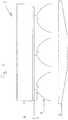
- a first embodiment of the illumination assembly of the invention 1is illustrated schematically in cross-section in Figure 1 .
- One or more white LEDs and one or more red-orange LEDs 2 on a printed circuit board 3are mounted in a housing (not shown).
- a heatsink 4To the rear of the printed circuit board 3 is a heatsink 4.
- Each LED 2is equipped with a beam shaping reflector 5.
- Light from the white and red-orange LEDspasses through a wedge lens 7 which converges and mixes the light beam into an output light to a spot.
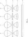
- FIGS 2A to 2Cillustrate in plan view second, third and fourth embodiments of the illumination assembly of the invention with a similar arrangement of parts to that of Figure 1 described above.
- narrow beam and wide beam white LEDs and red-orange LEDsare disposed in an array of hexagonal clusters. In each hexagonal cluster, a red-orange LED sits at the centre of the white LEDs.
- hexagonal clusters 6 of narrow beam red-orange LEDs and white LEDs (shaded) and hexagonal clusters 7 of wide beam white LEDs and red-orange LEDs (unshaded)are disposed in a hexagonal array which is capable of solid state focussing.
- a red-orange LEDlies at the centre of each cluster.
- hexagonal clusters 8 of alternating narrow beam (shaded) and wide beam (unshaded) white and red-orange LEDsare in a hexagonal array which is capable of solid state focussing.
- a red-orange LEDlies at the centre of each cluster.
- hexagonal clusters 9 of narrow beam (unshaded) white and red-orange LEDsare in a triangular array which is incapable of solid state focussing.
- a red-orange LEDlies at the centre of each cluster.
- FIG. 2Dillustrates in plan view a fifth embodiment with a similar arrangement of parts to that of Figure 1 described above or Figure 3 described below.
- white LEDs and red-orange LEDsare disposed in a complex array.
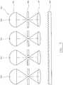
- a sixth embodiment of the assembly of the invention 61is illustrated schematically in cross-section in Figure 3 .
- One or more white LEDs and one or more red-orange LEDs 62are mounted in a housing (not shown).
- Each LED 62is positioned at a first focal point of an ellipsoidal reflector 65 which re-images the LED to the second focus of the ellipsoidal reflector 65 which is approximately in the same plane as an array of apertures 66.
- This second focusis then re-imaged by an array of lenses 67 to the field of interest (0.5-1m away).
- Mixed light from the white and red-orange LEDs 62passes through a converging Fresnel lens 69 which converges the light into an output light beam focussed onto a spot.
- the spot size at the field positioncan be adjusted. This gives a mechanical means for adjusting the beam size.
- Figure 4illustrates in plan view a seventh embodiment with a similar arrangement of parts to that of Figures 1 and 2 described above.
- White LEDs and red-orange LEDsare disposed in a honeycomb array with varying beam sizes (as denoted) to permit solid state focussing.
- An eighth embodiment of the illumination assembly of the invention 961is illustrated schematically in cross-section in Figure 5 .
- One or more white LEDs and one or more red-orange LEDs 962are mounted in a housing (not shown). Each LED 962 is positioned at a first focal point of an ellipsoidal reflector 965 which re-images the LED to the second focus of the ellipsoidal reflector 965 which is approximately in the same plane as an array of apertures 966. This second focus is then re-imaged by an array of lenses 967 to the field of interest (0.5-1m away).
- Mixed light from the white and red-orange LEDs 962passes through a converging Fresnel lens 969 which converges the light into an output light beam focussed onto a spot.
- the spot size at the field positioncan be adjusted. This gives a mechanical means for adjusting the beam size.
- Table 1Measured colour parameters from light generated using white LEDs and red-orange LEDs.
- the colour rendering index R9 and correlated colour temperature of combinations of red-orange LUXEON R LEDs with various white LUXEON R LEDswere measured (see Table 1).
- the net effect of the presence of the red-orange LED on the white LEDsis that the colour rendition of the source is improved at a particular correlated colour temperature.
- the light produced by the combination of the white LEDS from bins WN and WO and the red-orange LEDhas almost ideal characteristics for medical lighting ie it has an excellent colour rendering index (high R9 and Ra) at a desirable correlated colour temperature of about 4300K.
- the light produced by the combination of the white LEDS from bin VN and the red-orange LEDhas a lower correlated colour temperature with excellent colour rendition. This is an ideal light source for room lighting.
- the light produced by the combination of the white LEDS from bins XO or XN and the red-orange LEDhas a higher colour temperature with excellent colour rendition. This creates a good match to midday daylight.
Landscapes
- Engineering & Computer Science (AREA)
- General Engineering & Computer Science (AREA)
- Physics & Mathematics (AREA)
- Microelectronics & Electronic Packaging (AREA)
- Optics & Photonics (AREA)
- Non-Portable Lighting Devices Or Systems Thereof (AREA)
Description
- The present invention relates to an illumination assembly.
- In many applications, the spectral characteristics of a lighting system are critical and may be required to meet certain specifications. One particular example of such an application is medical lighting. A large number of devices exist for medical lighting ranging from large aperture operating theatre lights to lights for general examination and simple tasks. The specifications of these devices are the subject of International standard IEC 60601-2-41:2000. The precise characteristics of medical lighting devices are important to a user such as a surgeon, doctor or nurse.
- Until recently, the characteristics required of medical lighting devices have been provided using light configurations based on for example tungsten halogen bulbs. These bulbs are usually used in combination with reflector elements to gather the light from the source and project it into a spot or well defined beam 0.5m-1m in front of the reflector aperture. In addition, by using heat filter elements in front of the reflector aperture and/or incorporated into the reflector coating, the majority of the infra-red component of the beam can be removed. Colour shift filters are also used to produce specific colour temperatures. For example, Schott Glass type KG1 can be used to shift a tungsten halogen source at a colour temperature of about 3200K up to a colour temperature of ∼4300K.
- More recently, a number of manufacturers have started to produce medical lighting devices using high brightness light emitting diodes (LEDs).- Commercial examples of these include the iledR (Trumpf) which uses white, green and blue LEDs and the PENTALEDR (Rimsa) which uses a small number of high power, high lumen output cold white LEDs. Other commercial devices use LEDs to mix in warm white but the lumen output is low. Typically however these devices require a large number of LEDs to produce the requisite light output for medical lighting (eg typically 150 LEDs but often up to 300 LEDs for an operating theatre light). Moreover it is difficult to achieve a good colour rendering index (Ra and R9 in particular are usually low) because of the non-uniform spectral output (ie the spectrum has wavelength gaps). As a result of the large number of LEDs and associated hardware, the devices tend to be expensive with poor optical design and inefficient use of the LED light.
US-B-6636003 discloses an LED arrangement which produces white light with an adjustable colour temperature. The arrangement includes one or more white LEDs and one or more coloured LEDs (eg amber or red and yellow) to produce an output with a desired colour temperature in the range 2500-5000K. The desired colour temperature is adjusted using first and second driver circuits to control the output of the white LEDs and coloured LEDs respectively.WO-A-01/36864 EP-A-1462711 ,US-A-2006/285323 ,EP-A-1568935 andChenhua et al, Optical Engineering, vol 44, 11 (1 November 2005), 111307-1-111307-7 disclose various systems and methods for generating and modulating illumination conditions provided by lighting fixtures with a plurality of LEDs.- The present invention is based on the recognition of an improvement in the spectral characteristics (eg specific colour performance characteristics such as a desirable colour rendering index and colour temperature) of an illumination assembly using a specific combination of one or more white LEDs and one or more red-orange LEDs. In particular, the present invention provides an illumination assembly which transmits light from one or more white LEDs and light from one or more red-orange LEDs to achieve an output with a desirable colour rendering index and colour temperature.
- Thus the present invention provides an illumination assembly capable of emitting an output light according to claim 1. The illumination assembly of the present invention advantageously exhibits a high colour rendering index (as defined in CIE 13.3:1995) and a useful specific colour temperature. The level of performance is significantly higher than that which can be achieved by using white light LEDs alone. For example, using a minimal number of high brightness LEDs in the assembly of the invention, an extremely high level of colour performance may be achieved (eg high Ra and R9 can be achieved at a well-defined specific colour temperatures such as 4300K). The colour characteristics may approximate to those of a blackbody.
- Each of the one or more white LEDs and each of the one or more red-orange LEDs may be based on a light emitting polymer, semiconductor dye, organic species, electroluminescent or superluminescent. Specific examples include indium gallium nitride and aluminium indium gallium phosphide.
- Each of the one or more white LEDs and each of the one or more red-orange LEDs may be individually mounted in the housing. Each of the one or more white LEDs and each of the one or more red-orange LEDs may be tiltedly mounted in the housing. The output light may take the form of a beam. The output light may be focussed to a spot. By varying the position and tilt of the mounting of the one or more white LEDs or the one or more red-orange LEDs, it is possible in association with beam shaping elements (such as a focussing lens) to achieve a desired beam or spot size, profile and position.
- The one or more white LEDs and one or more red-orange LEDs are clustered. Each cluster may contain only white LEDs or only red-orange LEDs. Each cluster may contain red-orange LEDs and white LEDs which may be randomly distributed. Each cluster may contain red-orange LEDs and white LEDs which may be alternating. In the (or each) cluster, one or more white LEDs may surround a red-orange LED. The cluster may be a regular pattern. The cluster may be a linear, staggered (eg herringbone or honeycomb), triangular, hexagonal or circular pattern.
- The one or more white LEDs and one or more red-orange LEDs are provided in an array. The array is a plurality of discrete clusters (as described above).
- The array may be a regular pattern. The array may be a linear, staggered (eg herringbone or honeycomb), triangular, hexagonal or circular pattern.
- In a preferred embodiment, each of the one or more white LEDs is a high brightness white LED. Typically the lumen output per Watt is in excess of 15.
- In a preferred embodiment, each of the one or more white LEDs is a high power white LED. Typically the input power is 0.5W or more.
- The one or more white LEDs may be a single white LED. The one or more white LEDs may be 2 or more, preferably 3 or more, particularly preferably 4 or more, especially preferably 5 or more white LEDs.
- Each of the white LEDs may be a warm white, neutral white or cold white LED. Preferably each of the one or more white LEDs is a cold white LED. Cold white LEDs suitable for use in this embodiment are available commercially from Lumileds, Edixeon, Nichia, Cree and Osram.
- The white LEDs used in accordance with the invention have a correlated colour temperature in the range 5000-7000K.
- Preferably each of the one or more white LEDs is selected from a class of LEDs known as LUXEONR (Lumileds). A preferred white LED is a LUXEONR selected from the group consisting of UO, UN, WN, WO, XN, XO and VN, particularly preferably WN, WO, XN, XO and VN. Particularly preferred is a LUXEONR white LED from bin WO or WN, more preferably a LUXEONR white LED from bin WN.
- Preferably each of the one or more white LEDs is a LUXEONR, LUXEONR K2, LUXEONR K2 TFFC, LUXEONR REBEL, LUXEONR III or LUXEONR V LED. An example of a preferred white LED is LUXEONR REBEL LXML-PWC1.
- The one or more red-orange LEDs may be a single red-orange LED. The one or more red-orange LEDs may be 2 or more, preferably 3 or more, particularly preferably 4 or more, especially preferably 5 or more red-orange LEDs. According to the invention each of the one or more red-orange LEDs has a dominant wavelength in the range 613 to 621nm (eg about 617nm).
- Preferably each of the one or more red-orange LEDs is selected from a class of LEDs known as LUXEONR (Lumileds). Particularly preferably the LUXEONR red-orange LED is one from dominant wavelength bin 2.
- Preferably each of the one or more red-orange LEDs is a LUXEONR, LUXEONR K2, LUXEONR K2 TFFC, LUXEONR III, LUXEONR REBEL, LUXEONR Dental or LUXEONR V red-orange LED. Preferred is a LUXEONR REBEL red-orange LED. An example of a preferred red-orange LED is LUXEONR REBEL LXML-PH01.
- In a preferred embodiment of the assembly of the invention, the colour rendering index of the output light is substantially uniform across substantially the whole visible spectrum and is greater than 90. According to the invention, the colour rendering index Ra of the output light is 90 or more, particularly preferably 91 or more, more preferably 92 or more, especially preferably 93 or more, yet more preferably 94 or more, even more preferably 95 or more, yet even more preferably 96 or more, still even more preferably 97 or more, most preferably 98 or more. Preferably, the colour rendering index R9 of the output light is 90 or more, particularly preferably 91 or more, more preferably 92 or more, especially preferably 93 or more, yet more preferably 94 or more, even more preferably 95 or more, yet even more preferably 96 or more, still even more preferably 97 or more, most preferably 98 or more. Preferably, each of the colour rendering indices R1 to R8 of the output light is 80 or more, preferably 85 or more, particularly preferably 90 or more, more preferably 91 or more, especially preferably 92 or more, most preferably 93 or more. Preferably, each of the colour rendering indices R1 to R14 of the output light is 80 or more, preferably 85 or more, particularly preferably 90 or more, more preferably 91 or more, especially preferably 92 or more, most preferably 93 or more. According to the invention, the output light has a correlated colour temperature in the range 4000 to 4600K (eg about 4300K) .
- Preferably the illumination device further comprises: one or more converging elements positioned relative to the one or more white LEDs and one or more red-orange LEDs to manipulate the first light and second light to form the output light.
- The (or each) converging element may be a focussing element or beam shaping element or beam converging element.
- The output light may be converged to a beam or spot. The spot (or beam) size may be 100-400mm in diameter. The output light may be focussed to a spot (eg a round spot) 0.5m or more (eg up to 1m) in front of the assembly (reference to D10). An advantage of the present invention is that it permits the converging element to produce a broad spot of uniform intensity (in contrast to the Gaussian distribution of the intensity of a spot observed in accordance with conventional arrangements).
- The (or each) converging element is preferably a reflector element. The (or each) reflector element may be a beam shaping reflector such as an ellipsoidal reflector element. The LED is typically positioned at or near to a first focal point of the ellipsoidal reflector element. The spot may be at the second focal point of the ellipsoidal reflector element. The reflector element may be a large aperture reflector element.
- In a preferred embodiment, the reflector element is a single reflector element.
- In a preferred embodiment, the one or more white LEDs and one or more red-orange LEDs are clustered into a plurality of clusters, wherein the device further comprises:
- a plurality of reflector elements, wherein a reflector element is positioned discretely relative to each cluster to converge the first light and the second light from each cluster to form the output light.
- The (or each) converging element is preferably a lens. The lens may be a movable focussing lens. The lens may be a static converging lens. The lens may be a beam shaping lens such as a TIR lens, a spheric or aspheric lens (such as condenser, Fresnel or diffractive lenses). The lens may be a beam converging lens such a wedge lens, Fresnel lens, spheric or aspheric lens.
- Preferably the beam size of the first light from the one or more white LEDs is variable relative to the beam size of the second light from the one or more red-orange LEDs. The one or more white LEDs and one or more red-orange LEDs may be clustered and the beam size of the first, second or output light from the clusters may be varied.
- In a preferred embodiment, the beam size of the first light from the one or more white LEDs is independently adjustable.
- In a preferred embodiment, the beam size of the second light from the one or more red-orange LEDs is independently adjustable.
- Preferably the intensity of the first light from the one or more white LEDs is variable relative to the intensity of the second light from the one or more red-orange LEDs. This allows the colour rendition to be optimised at a particular colour temperature and varied as required.
- In a preferred embodiment, the intensity of the first light from each of the one or more white LEDs is independently adjustable.
- In a preferred embodiment, the intensity of the second light from the one or more red-orange LEDs is independently adjustable.
- In a preferred embodiment, the device is capable of performing solid state focussing. According to the invention, the one or more white LEDs and one or more red-orange LEDs are provided in an array, wherein the array is a plurality of discrete first and second clusters. Preferably each first cluster in this embodiment is a cluster of narrow beam LEDs and each second cluster is a cluster of broad beam LEDs. Preferably the beam size of the output light from the first cluster is narrower than the beam size of the output light from the second cluster. The difference between the beam size of the output light from the first cluster and the beam size of the output light from the second cluster may be variable. Alternatively preferably each first cluster and each second cluster in this embodiment is a cluster of narrow beam LEDs and broad beam LEDs. Preferably the intensity of the output light from the first cluster is variable relative to the intensity of the output light from the second cluster. The variability of the intensity permits the beam size (spot diameter) to be controlled (ie change focus) where the narrow and broad beam sizes are fixed.
- The device may further comprise a heat sink. Typically the heat sink is mounted rearwardly in the housing. A controller and processor may be included in the device to control the LEDs in accordance with known techniques. Typically the housing is a luminaire. The illumination assembly may further comprise a measuring device for measuring the operating temperature; a power device for supplying power to the one or more white LEDs and one or more red-orange LEDs; and a power adjustment device operatively connected to the measuring device and to the power device, wherein in use the power adjustment device causes the power device to adjust the power supply in response to a change in the operating temperature.
- The measuring device may be a thermistor. The power adjustment device may be an integrated circuit.
- The assembly of the present invention may be used in domestic or commercial applications. The applications may be medical (eg surgical or diagnostic) or non-medical (eg in forensic science, retail displays, museums and exhibitions, studio lighting, room lighting, architectural or machine vision). The assembly of the present invention may be used in colour matching (eg checking print quality). The assembly may be chip-mounted. With regard to medical lighting, the assembly of the invention enables high quality light to be produced from LED sources with excellent colour rendering characteristics at specific colour temperatures. It also enables the colour temperature to be adjusted, by altering the red-orange mix.
- In a preferred embodiment, the illumination assembly is without a colour filter in the path of the output light (eg in the third path or at the field position). According to the invention, the illumination assembly is without a colour filter in the first path of the light and without a colour filter in the second path of the second light.
- The present invention will now be described in a non-limitative sense with reference to examples and to the accompanying Figures in which:
Figure 1 : A first embodiment of the illumination assembly of the invention shown schematically in cross-section;Figures 2A to 2D : A plan view of a second, third, fourth and fifth embodiment of the illumination assembly of the invention;Figure 3 : A sixth embodiment of the illumination assembly of the invention shown schematically in cross-section;Figure 4 : A plan view of a seventh embodiment of the illumination assembly of the invention; andFigure 5 : An eighth embodiment of the illumination assembly of the invention shown schematically in cross-section.- A first embodiment of the illumination assembly of the invention 1 is illustrated schematically in cross-section in
Figure 1 . One or more white LEDs and one or more red-orange LEDs 2 on a printedcircuit board 3 are mounted in a housing (not shown). To the rear of the printedcircuit board 3 is aheatsink 4. Each LED 2 is equipped with a beam shaping reflector 5. Light from the white and red-orange LEDs passes through awedge lens 7 which converges and mixes the light beam into an output light to a spot. Figures 2A to 2C illustrate in plan view second, third and fourth embodiments of the illumination assembly of the invention with a similar arrangement of parts to that ofFigure 1 described above. In these embodiments, narrow beam and wide beam white LEDs and red-orange LEDs are disposed in an array of hexagonal clusters. In each hexagonal cluster, a red-orange LED sits at the centre of the white LEDs.- In the second embodiment (
Figure 2A ),hexagonal clusters 6 of narrow beam red-orange LEDs and white LEDs (shaded) andhexagonal clusters 7 of wide beam white LEDs and red-orange LEDs (unshaded) are disposed in a hexagonal array which is capable of solid state focussing. A red-orange LED lies at the centre of each cluster. - In the third embodiment (
Figure 2B ),hexagonal clusters 8 of alternating narrow beam (shaded) and wide beam (unshaded) white and red-orange LEDs are in a hexagonal array which is capable of solid state focussing. A red-orange LED lies at the centre of each cluster. - In the fourth embodiment (
Figure 2C ),hexagonal clusters 9 of narrow beam (unshaded) white and red-orange LEDs are in a triangular array which is incapable of solid state focussing. A red-orange LED lies at the centre of each cluster. Figure 2D illustrates in plan view a fifth embodiment with a similar arrangement of parts to that ofFigure 1 described above orFigure 3 described below. In this embodiment, white LEDs and red-orange LEDs are disposed in a complex array.- A sixth embodiment of the assembly of the
invention 61 is illustrated schematically in cross-section inFigure 3 . One or more white LEDs and one or more red-orange LEDs 62 are mounted in a housing (not shown). EachLED 62 is positioned at a first focal point of anellipsoidal reflector 65 which re-images the LED to the second focus of theellipsoidal reflector 65 which is approximately in the same plane as an array ofapertures 66. This second focus is then re-imaged by an array oflenses 67 to the field of interest (0.5-1m away). Mixed light from the white and red-orange LEDs 62 passes through a convergingFresnel lens 69 which converges the light into an output light beam focussed onto a spot. By mechanically moving the array oflenses 67 the spot size at the field position can be adjusted. This gives a mechanical means for adjusting the beam size. Figure 4 illustrates in plan view a seventh embodiment with a similar arrangement of parts to that ofFigures 1 and2 described above. White LEDs and red-orange LEDs are disposed in a honeycomb array with varying beam sizes (as denoted) to permit solid state focussing.- An eighth embodiment of the illumination assembly of the
invention 961 is illustrated schematically in cross-section inFigure 5 . One or more white LEDs and one or more red-orange LEDs 962 are mounted in a housing (not shown). EachLED 962 is positioned at a first focal point of anellipsoidal reflector 965 which re-images the LED to the second focus of theellipsoidal reflector 965 which is approximately in the same plane as an array ofapertures 966. This second focus is then re-imaged by an array oflenses 967 to the field of interest (0.5-1m away). Mixed light from the white and red-orange LEDs 962 passes through a convergingFresnel lens 969 which converges the light into an output light beam focussed onto a spot. By mechanically moving the array oflenses 967, the spot size at the field position can be adjusted. This gives a mechanical means for adjusting the beam size. Table 1: Measured colour parameters from light generated using white LEDs and red-orange LEDs. white bin peak CRI CCT R9 VN 91.1 3502 89.8 W0 89.9 4368 93.4 WN 94.4 4280 94.2 X0 90 5181 86.7 XN 90.5 5416 90.5 - The colour rendering index R9 and correlated colour temperature of combinations of red-orange LUXEONR LEDs with various white LUXEONR LEDs were measured (see Table 1). The net effect of the presence of the red-orange LED on the white LEDs is that the colour rendition of the source is improved at a particular correlated colour temperature.
- The light produced by the combination of the white LEDS from bins WN and WO and the red-orange LED has almost ideal characteristics for medical lightingie it has an excellent colour rendering index (high R9 and Ra) at a desirable correlated colour temperature of about 4300K.
- The light produced by the combination of the white LEDS from bin VN and the red-orange LED has a lower correlated colour temperature with excellent colour rendition. This is an ideal light source for room lighting.
- The light produced by the combination of the white LEDS from bins XO or XN and the red-orange LED has a higher colour temperature with excellent colour rendition. This creates a good match to midday daylight.
Claims (8)
- An illumination assembly capable of emitting an output light comprising:a housing; andone or more white LEDs emitting a first light along a first path and one or more red-orange LEDs emitting a second light along a second path, wherein the one or more white LEDs and the one or more red-orange LEDs are mounted in the housing such that the first light and the second light are mixed to form the output light transmitted along a third path or to form the output light at a field position, wherein the chromaticity coordinate (X) of each of the one or more white LEDs is in the range 0.300 to 0.350 and the chromaticity coordinate (Y) of each of the one or more white LEDs is in the range 0.310 to 0.3750, wherein the white LEDs have a correlated colour temperature in the range 5000-7000K and wherein each of the one or more red-orange LEDs has a dominant wavelength in the range 613 to 621nm whereby the colour rendering index Ra of the output light is 90 or more and the output light has a correlated colour temperature in the range 4000 to 4600Kwherein the one or more white LEDs and one or more red-orange LEDs are provided in an array, wherein the array is a plurality of discrete first and second clusters and wherein either each first cluster is a cluster of narrow beam LEDs and each second cluster is a cluster of broad beam LEDs or each first cluster and each second cluster is a cluster of narrow beam LEDs and broad beam LEDs.
without a colour filter in the first path of the light and without a colour filter in the second path of the second light, - An illumination assembly as claimed in claim 1 wherein each of the one or more white LEDs is a cold white LED.
- An illumination assembly as claimed in any preceding claim wherein each of the one or more white LEDs is a LUXEONR white LED selected from the group consisting of bin WN, UN, U0, WO, XN, XO and VN.
- An illumination assembly as claimed in any preceding claim wherein each of the one or more white LEDs is a LUXEONR white LED selected from the group consisting of bin WO or WN.
- An illumination assembly as claimed in claim 1 wherein the beam size of the output light from the first cluster is narrower than the beam size of the output light from the second cluster.
- An illumination assembly as claimed in any preceding claim wherein the difference between the beam size of the output light from the first cluster and the beam size of the output light from the second cluster is variable.
- An illumination assembly as claimed in any preceding claim wherein the intensity of the output light from the first cluster is variable relative to the intensity of the output light from the second cluster.
- An illumination assembly as claimed in any preceding claim wherein the intensity of the first light from the one or more white LEDs is variable relative to the intensity of the second light from the one or more red-orange LEDs.
Applications Claiming Priority (3)
| Application Number | Priority Date | Filing Date | Title |
|---|---|---|---|
| PCT/GB2008/000142WO2008087404A1 (en) | 2007-01-18 | 2008-01-16 | Illumination device |
| GBGB0813834.9AGB0813834D0 (en) | 2008-07-29 | 2008-07-29 | Illumination assembly |
| PCT/GB2009/000005WO2009090365A1 (en) | 2008-01-16 | 2009-01-06 | Illumination assembly |
Publications (2)
| Publication Number | Publication Date |
|---|---|
| EP2232126A1 EP2232126A1 (en) | 2010-09-29 |
| EP2232126B1true EP2232126B1 (en) | 2017-09-13 |
Family
ID=39748511
Family Applications (1)
| Application Number | Title | Priority Date | Filing Date |
|---|---|---|---|
| EP09702366.7AActiveEP2232126B1 (en) | 2008-01-16 | 2009-01-06 | Illumination assembly |
Country Status (4)
| Country | Link |
|---|---|
| US (3) | US8672507B2 (en) |
| EP (1) | EP2232126B1 (en) |
| GB (1) | GB0813834D0 (en) |
| WO (1) | WO2009090365A1 (en) |
Families Citing this family (13)
| Publication number | Priority date | Publication date | Assignee | Title |
|---|---|---|---|---|
| GB0813834D0 (en)* | 2008-07-29 | 2008-09-03 | Brandon Medical Company Ltd | Illumination assembly |
| US8657463B2 (en)* | 2010-07-01 | 2014-02-25 | Jan Flemming Samuel Lichten | Lighting fixture for a poultry house |
| US9279564B1 (en) | 2011-08-11 | 2016-03-08 | Universal Lighting Technologies, Inc. | Indirect area lighting apparatus and methods |
| DE202013011694U1 (en)* | 2012-01-16 | 2014-02-25 | Ludwig Leuchten Kg | Optical diagnostic device |
| US20140104321A1 (en)* | 2012-10-11 | 2014-04-17 | Gary Steffy | System of adjusting electronic displays and lighting to a circadian rhythm |
| EP3141085A1 (en)* | 2014-05-06 | 2017-03-15 | Philips Lighting Holding B.V. | Methods and apparatus for color mixing via angular light output modification |
| CN104821161B (en)* | 2015-05-29 | 2018-05-08 | 京东方科技集团股份有限公司 | Driving method, the driving method of field sequential display device of a kind of sequence display panel |
| US10989371B2 (en)* | 2018-03-09 | 2021-04-27 | Blooming International Limited | Dual-color light emitting diode light strings |
| US10845036B2 (en) | 2018-03-09 | 2020-11-24 | Blooming International Limited | Dual-color light strings |
| CN209399201U (en)* | 2019-01-15 | 2019-09-17 | 漳州立达信灯具有限公司 | a lamp |
| EP3889493A1 (en)* | 2020-03-30 | 2021-10-06 | TRUMPF Medizin Systeme GmbH + Co. KG | Surgical light system and method for operating the surgical light system |
| US20240125459A1 (en)* | 2022-10-18 | 2024-04-18 | SeaLife Pioneer & Co., Inc. d/b/a Pioneer Research | Underwater light with switchable color temperature |
| DE102023118697A1 (en)* | 2023-07-14 | 2025-01-16 | optical design unit gmbh | LED arrangement with adjustable color temperature and constant color rendering |
Citations (1)
| Publication number | Priority date | Publication date | Assignee | Title |
|---|---|---|---|---|
| US20020070681A1 (en)* | 2000-05-31 | 2002-06-13 | Masanori Shimizu | Led lamp |
Family Cites Families (24)
| Publication number | Priority date | Publication date | Assignee | Title |
|---|---|---|---|---|
| TW417842U (en)* | 1998-09-28 | 2001-01-01 | Koninkl Philips Electronics Nv | Lighting system |
| JP2003517705A (en) | 1999-11-18 | 2003-05-27 | カラー・キネティックス・インコーポレーテッド | System and method for generating and adjusting lighting conditions |
| DE10034594B4 (en) | 2000-07-14 | 2006-03-16 | Sirona Dental Systems Gmbh | Dental treatment light |
| US6636003B2 (en)* | 2000-09-06 | 2003-10-21 | Spectrum Kinetics | Apparatus and method for adjusting the color temperature of white semiconduct or light emitters |
| US6483651B1 (en) | 2001-05-09 | 2002-11-19 | Scott D. Maurer | Lighted magnifying device incorporating a light emitting diode |
| JP3940596B2 (en)* | 2001-05-24 | 2007-07-04 | 松下電器産業株式会社 | Illumination light source |
| WO2003019072A1 (en)* | 2001-08-23 | 2003-03-06 | Yukiyasu Okumura | Color temperature-regulable led light |
| US20060237636A1 (en)* | 2003-06-23 | 2006-10-26 | Advanced Optical Technologies, Llc | Integrating chamber LED lighting with pulse amplitude modulation to set color and/or intensity of output |
| US7777430B2 (en)* | 2003-09-12 | 2010-08-17 | Terralux, Inc. | Light emitting diode replacement lamp |
| US7144121B2 (en)* | 2003-11-14 | 2006-12-05 | Light Prescriptions Innovators, Llc | Dichroic beam combiner utilizing blue LED with green phosphor |
| US7095056B2 (en)* | 2003-12-10 | 2006-08-22 | Sensor Electronic Technology, Inc. | White light emitting device and method |
| DE502004003272D1 (en)* | 2004-02-28 | 2007-05-03 | Trumpf Kreuzer Med Sys Gmbh | surgical light |
| JP2008505433A (en)* | 2004-06-29 | 2008-02-21 | 松下電器産業株式会社 | Illumination light source |
| KR20060000544A (en)* | 2004-06-29 | 2006-01-06 | 삼성전자주식회사 | Backlight for display device, Light source for display device, Light emitting diode for light source |
| EP1647763A1 (en) | 2004-10-12 | 2006-04-19 | Scanatron Technics AG | Surgical or medical illuminating device with optimized LED light source |
| GB0512256D0 (en)* | 2005-06-16 | 2005-07-27 | Fowler James A | Lighting device |
| CA2614575C (en)* | 2005-04-06 | 2015-03-31 | Tir Technology Lp | White light luminaire with adjustable correlated colour temperature |
| DE102005043783A1 (en) | 2005-04-16 | 2006-10-26 | Elosoft Systemtechnik Gmbh | System for generating light utilises at least one semi-conductor element and does not use, in variants, reflectors, infra-red or ultra-violet light |
| EP1741975B1 (en) | 2005-07-05 | 2011-09-07 | Frowein EZH GmbH | Operating lamp |
| EP1963740A4 (en)* | 2005-12-21 | 2009-04-29 | Cree Led Lighting Solutions | Lighting device and lighting method |
| CA2884517C (en)* | 2006-12-24 | 2017-01-24 | Brasscorp Limited | Led lamps including led work lights |
| WO2008087404A1 (en)* | 2007-01-18 | 2008-07-24 | Brandon Medical Company Limited | Illumination device |
| JP4804421B2 (en)* | 2007-05-30 | 2011-11-02 | 三菱電機株式会社 | Lighting device and lighting fixture |
| GB0813834D0 (en)* | 2008-07-29 | 2008-09-03 | Brandon Medical Company Ltd | Illumination assembly |
- 2008
- 2008-07-29GBGBGB0813834.9Apatent/GB0813834D0/ennot_activeCeased
- 2009
- 2009-01-06EPEP09702366.7Apatent/EP2232126B1/enactiveActive
- 2009-01-06WOPCT/GB2009/000005patent/WO2009090365A1/enactiveApplication Filing
- 2010
- 2010-06-29USUS12/825,943patent/US8672507B2/enactiveActive
- 2014
- 2014-01-28USUS14/166,072patent/US9581301B2/enactiveActive
- 2014-01-28USUS14/166,113patent/US9423081B2/enactiveActive
Patent Citations (1)
| Publication number | Priority date | Publication date | Assignee | Title |
|---|---|---|---|---|
| US20020070681A1 (en)* | 2000-05-31 | 2002-06-13 | Masanori Shimizu | Led lamp |
Non-Patent Citations (1)
| Title |
|---|
| RICHARD COMERFORD: "LED Specs - Understanding the Color White | DigiKey", 10 May 2011 (2011-05-10), XP055324654, Retrieved from the Internet <URL:http://www.digikey.com/en/articles/techzone/2011/may/led-specs---understanding-the-color-white> [retrieved on 20161130]* |
Also Published As
| Publication number | Publication date |
|---|---|
| US20140140058A1 (en) | 2014-05-22 |
| GB0813834D0 (en) | 2008-09-03 |
| US9581301B2 (en) | 2017-02-28 |
| US8672507B2 (en) | 2014-03-18 |
| WO2009090365A1 (en) | 2009-07-23 |
| US20140140057A1 (en) | 2014-05-22 |
| US20100265703A1 (en) | 2010-10-21 |
| EP2232126A1 (en) | 2010-09-29 |
| US9423081B2 (en) | 2016-08-23 |
Similar Documents
| Publication | Publication Date | Title |
|---|---|---|
| EP2232126B1 (en) | Illumination assembly | |
| EP2458264B1 (en) | Illumination device | |
| JP6802803B2 (en) | Multi-channel lamp system and method using mixed spectrum | |
| US9585224B2 (en) | Color tuning of a multi-color LED based illumination device | |
| US8783885B2 (en) | Operating light and a process for lighting an operating table by means of an operating light | |
| US9222628B2 (en) | Color temperature tunable LED-based lamp module | |
| EP2584251B1 (en) | A light source unit, an illuminating device equipped with the light source unit and medical equipment | |
| US20120224371A1 (en) | Lighting apparatus | |
| CN102367925A (en) | Color temperature continuous adjusting method of light emitting diode (LED) operating astral lamp and product | |
| JP5188540B2 (en) | LED lighting fixtures | |
| US20120286306A1 (en) | Diffusely radiating led light system | |
| WO2012107863A1 (en) | Method for color mixing | |
| US20120044676A1 (en) | Structure of light-emitting diode (LED) lamp | |
| NL2012037C2 (en) | Materials and process for spatial s/p ratio distribution. | |
| WO2021007212A2 (en) | Systems and methods for targeted spectral illumination | |
| Aladov et al. | POLYCHROME SPECTRALLY CHANGEABLE ILLUMINATION DEVICES WITH LIGHT EMITTING DIODES: EXPERIENCE OF DEVELOPMENT AND APPLICATION. | |
| Moisio et al. | Use of junction temperature in control of CCT in LED luminaire | |
| GB2566108A (en) | Variable beam angle lighting unit | |
| WO2016171631A1 (en) | Led illuminating device with multi-segment directional optics | |
| WO2021244942A1 (en) | Led system with high melanopic efficiency ratio | |
| JP2017500693A (en) | Method and apparatus for uniformly illuminating a surface |
Legal Events
| Date | Code | Title | Description |
|---|---|---|---|
| PUAI | Public reference made under article 153(3) epc to a published international application that has entered the european phase | Free format text:ORIGINAL CODE: 0009012 | |
| 17P | Request for examination filed | Effective date:20100323 | |
| AK | Designated contracting states | Kind code of ref document:A1 Designated state(s):AT BE BG CH CY CZ DE DK EE ES FI FR GB GR HR HU IE IS IT LI LT LU LV MC MK MT NL NO PL PT RO SE SI SK TR | |
| AX | Request for extension of the european patent | Extension state:AL BA RS | |
| DAX | Request for extension of the european patent (deleted) | ||
| RAP1 | Party data changed (applicant data changed or rights of an application transferred) | Owner name:BRANDON MEDICAL COMPANY LIMITED | |
| 17Q | First examination report despatched | Effective date:20150609 | |
| REG | Reference to a national code | Ref country code:DE Ref legal event code:R079 Ref document number:602009048302 Country of ref document:DE Free format text:PREVIOUS MAIN CLASS: F21S0008000000 Ipc:F21Y0115100000 | |
| GRAP | Despatch of communication of intention to grant a patent | Free format text:ORIGINAL CODE: EPIDOSNIGR1 | |
| STAA | Information on the status of an ep patent application or granted ep patent | Free format text:STATUS: GRANT OF PATENT IS INTENDED | |
| RIC1 | Information provided on ipc code assigned before grant | Ipc:F21Y 113/13 20160101ALI20170406BHEP Ipc:F21Y 115/10 20160101AFI20170406BHEP | |
| INTG | Intention to grant announced | Effective date:20170428 | |
| GRAS | Grant fee paid | Free format text:ORIGINAL CODE: EPIDOSNIGR3 | |
| GRAA | (expected) grant | Free format text:ORIGINAL CODE: 0009210 | |
| STAA | Information on the status of an ep patent application or granted ep patent | Free format text:STATUS: THE PATENT HAS BEEN GRANTED | |
| AK | Designated contracting states | Kind code of ref document:B1 Designated state(s):AT BE BG CH CY CZ DE DK EE ES FI FR GB GR HR HU IE IS IT LI LT LU LV MC MK MT NL NO PL PT RO SE SI SK TR | |
| REG | Reference to a national code | Ref country code:GB Ref legal event code:FG4D | |
| REG | Reference to a national code | Ref country code:CH Ref legal event code:EP | |
| REG | Reference to a national code | Ref country code:IE Ref legal event code:FG4D | |
| REG | Reference to a national code | Ref country code:AT Ref legal event code:REF Ref document number:928531 Country of ref document:AT Kind code of ref document:T Effective date:20171015 | |
| REG | Reference to a national code | Ref country code:DE Ref legal event code:R096 Ref document number:602009048302 Country of ref document:DE | |
| REG | Reference to a national code | Ref country code:NL Ref legal event code:MP Effective date:20170913 | |
| REG | Reference to a national code | Ref country code:FR Ref legal event code:PLFP Year of fee payment:10 | |
| REG | Reference to a national code | Ref country code:LT Ref legal event code:MG4D | |
| PG25 | Lapsed in a contracting state [announced via postgrant information from national office to epo] | Ref country code:SE Free format text:LAPSE BECAUSE OF FAILURE TO SUBMIT A TRANSLATION OF THE DESCRIPTION OR TO PAY THE FEE WITHIN THE PRESCRIBED TIME-LIMIT Effective date:20170913 Ref country code:LT Free format text:LAPSE BECAUSE OF FAILURE TO SUBMIT A TRANSLATION OF THE DESCRIPTION OR TO PAY THE FEE WITHIN THE PRESCRIBED TIME-LIMIT Effective date:20170913 Ref country code:NO Free format text:LAPSE BECAUSE OF FAILURE TO SUBMIT A TRANSLATION OF THE DESCRIPTION OR TO PAY THE FEE WITHIN THE PRESCRIBED TIME-LIMIT Effective date:20171213 Ref country code:HR Free format text:LAPSE BECAUSE OF FAILURE TO SUBMIT A TRANSLATION OF THE DESCRIPTION OR TO PAY THE FEE WITHIN THE PRESCRIBED TIME-LIMIT Effective date:20170913 | |
| REG | Reference to a national code | Ref country code:AT Ref legal event code:MK05 Ref document number:928531 Country of ref document:AT Kind code of ref document:T Effective date:20170913 | |
| PG25 | Lapsed in a contracting state [announced via postgrant information from national office to epo] | Ref country code:BG Free format text:LAPSE BECAUSE OF FAILURE TO SUBMIT A TRANSLATION OF THE DESCRIPTION OR TO PAY THE FEE WITHIN THE PRESCRIBED TIME-LIMIT Effective date:20171213 Ref country code:GR Free format text:LAPSE BECAUSE OF FAILURE TO SUBMIT A TRANSLATION OF THE DESCRIPTION OR TO PAY THE FEE WITHIN THE PRESCRIBED TIME-LIMIT Effective date:20171214 Ref country code:ES Free format text:LAPSE BECAUSE OF FAILURE TO SUBMIT A TRANSLATION OF THE DESCRIPTION OR TO PAY THE FEE WITHIN THE PRESCRIBED TIME-LIMIT Effective date:20170913 Ref country code:LV Free format text:LAPSE BECAUSE OF FAILURE TO SUBMIT A TRANSLATION OF THE DESCRIPTION OR TO PAY THE FEE WITHIN THE PRESCRIBED TIME-LIMIT Effective date:20170913 | |
| PG25 | Lapsed in a contracting state [announced via postgrant information from national office to epo] | Ref country code:NL Free format text:LAPSE BECAUSE OF FAILURE TO SUBMIT A TRANSLATION OF THE DESCRIPTION OR TO PAY THE FEE WITHIN THE PRESCRIBED TIME-LIMIT Effective date:20170913 | |
| PG25 | Lapsed in a contracting state [announced via postgrant information from national office to epo] | Ref country code:CZ Free format text:LAPSE BECAUSE OF FAILURE TO SUBMIT A TRANSLATION OF THE DESCRIPTION OR TO PAY THE FEE WITHIN THE PRESCRIBED TIME-LIMIT Effective date:20170913 Ref country code:PL Free format text:LAPSE BECAUSE OF FAILURE TO SUBMIT A TRANSLATION OF THE DESCRIPTION OR TO PAY THE FEE WITHIN THE PRESCRIBED TIME-LIMIT Effective date:20170913 Ref country code:RO Free format text:LAPSE BECAUSE OF FAILURE TO SUBMIT A TRANSLATION OF THE DESCRIPTION OR TO PAY THE FEE WITHIN THE PRESCRIBED TIME-LIMIT Effective date:20170913 | |
| PG25 | Lapsed in a contracting state [announced via postgrant information from national office to epo] | Ref country code:AT Free format text:LAPSE BECAUSE OF FAILURE TO SUBMIT A TRANSLATION OF THE DESCRIPTION OR TO PAY THE FEE WITHIN THE PRESCRIBED TIME-LIMIT Effective date:20170913 Ref country code:SK Free format text:LAPSE BECAUSE OF FAILURE TO SUBMIT A TRANSLATION OF THE DESCRIPTION OR TO PAY THE FEE WITHIN THE PRESCRIBED TIME-LIMIT Effective date:20170913 Ref country code:EE Free format text:LAPSE BECAUSE OF FAILURE TO SUBMIT A TRANSLATION OF THE DESCRIPTION OR TO PAY THE FEE WITHIN THE PRESCRIBED TIME-LIMIT Effective date:20170913 Ref country code:IS Free format text:LAPSE BECAUSE OF FAILURE TO SUBMIT A TRANSLATION OF THE DESCRIPTION OR TO PAY THE FEE WITHIN THE PRESCRIBED TIME-LIMIT Effective date:20180113 Ref country code:IT Free format text:LAPSE BECAUSE OF FAILURE TO SUBMIT A TRANSLATION OF THE DESCRIPTION OR TO PAY THE FEE WITHIN THE PRESCRIBED TIME-LIMIT Effective date:20170913 | |
| REG | Reference to a national code | Ref country code:DE Ref legal event code:R097 Ref document number:602009048302 Country of ref document:DE | |
| PLBE | No opposition filed within time limit | Free format text:ORIGINAL CODE: 0009261 | |
| STAA | Information on the status of an ep patent application or granted ep patent | Free format text:STATUS: NO OPPOSITION FILED WITHIN TIME LIMIT | |
| PG25 | Lapsed in a contracting state [announced via postgrant information from national office to epo] | Ref country code:DK Free format text:LAPSE BECAUSE OF FAILURE TO SUBMIT A TRANSLATION OF THE DESCRIPTION OR TO PAY THE FEE WITHIN THE PRESCRIBED TIME-LIMIT Effective date:20170913 | |
| 26N | No opposition filed | Effective date:20180614 | |
| REG | Reference to a national code | Ref country code:CH Ref legal event code:PL | |
| PG25 | Lapsed in a contracting state [announced via postgrant information from national office to epo] | Ref country code:LU Free format text:LAPSE BECAUSE OF NON-PAYMENT OF DUE FEES Effective date:20180106 | |
| REG | Reference to a national code | Ref country code:IE Ref legal event code:MM4A | |
| REG | Reference to a national code | Ref country code:BE Ref legal event code:MM Effective date:20180131 | |
| PG25 | Lapsed in a contracting state [announced via postgrant information from national office to epo] | Ref country code:CH Free format text:LAPSE BECAUSE OF NON-PAYMENT OF DUE FEES Effective date:20180131 Ref country code:LI Free format text:LAPSE BECAUSE OF NON-PAYMENT OF DUE FEES Effective date:20180131 Ref country code:BE Free format text:LAPSE BECAUSE OF NON-PAYMENT OF DUE FEES Effective date:20180131 Ref country code:SI Free format text:LAPSE BECAUSE OF FAILURE TO SUBMIT A TRANSLATION OF THE DESCRIPTION OR TO PAY THE FEE WITHIN THE PRESCRIBED TIME-LIMIT Effective date:20170913 | |
| PG25 | Lapsed in a contracting state [announced via postgrant information from national office to epo] | Ref country code:IE Free format text:LAPSE BECAUSE OF NON-PAYMENT OF DUE FEES Effective date:20180106 | |
| PG25 | Lapsed in a contracting state [announced via postgrant information from national office to epo] | Ref country code:MC Free format text:LAPSE BECAUSE OF FAILURE TO SUBMIT A TRANSLATION OF THE DESCRIPTION OR TO PAY THE FEE WITHIN THE PRESCRIBED TIME-LIMIT Effective date:20170913 | |
| PG25 | Lapsed in a contracting state [announced via postgrant information from national office to epo] | Ref country code:MT Free format text:LAPSE BECAUSE OF NON-PAYMENT OF DUE FEES Effective date:20180106 | |
| PG25 | Lapsed in a contracting state [announced via postgrant information from national office to epo] | Ref country code:TR Free format text:LAPSE BECAUSE OF FAILURE TO SUBMIT A TRANSLATION OF THE DESCRIPTION OR TO PAY THE FEE WITHIN THE PRESCRIBED TIME-LIMIT Effective date:20170913 | |
| PG25 | Lapsed in a contracting state [announced via postgrant information from national office to epo] | Ref country code:HU Free format text:LAPSE BECAUSE OF FAILURE TO SUBMIT A TRANSLATION OF THE DESCRIPTION OR TO PAY THE FEE WITHIN THE PRESCRIBED TIME-LIMIT; INVALID AB INITIO Effective date:20090106 Ref country code:PT Free format text:LAPSE BECAUSE OF FAILURE TO SUBMIT A TRANSLATION OF THE DESCRIPTION OR TO PAY THE FEE WITHIN THE PRESCRIBED TIME-LIMIT Effective date:20170913 | |
| PG25 | Lapsed in a contracting state [announced via postgrant information from national office to epo] | Ref country code:MK Free format text:LAPSE BECAUSE OF NON-PAYMENT OF DUE FEES Effective date:20170913 Ref country code:CY Free format text:LAPSE BECAUSE OF FAILURE TO SUBMIT A TRANSLATION OF THE DESCRIPTION OR TO PAY THE FEE WITHIN THE PRESCRIBED TIME-LIMIT Effective date:20170913 | |
| PGFP | Annual fee paid to national office [announced via postgrant information from national office to epo] | Ref country code:DE Payment date:20250127 Year of fee payment:17 | |
| PGFP | Annual fee paid to national office [announced via postgrant information from national office to epo] | Ref country code:FI Payment date:20250128 Year of fee payment:17 | |
| PGFP | Annual fee paid to national office [announced via postgrant information from national office to epo] | Ref country code:FR Payment date:20250131 Year of fee payment:17 | |
| PGFP | Annual fee paid to national office [announced via postgrant information from national office to epo] | Ref country code:GB Payment date:20250130 Year of fee payment:17 |