EP2231040B1 - Single use, disposable, uterine manipulator - Google Patents
Single use, disposable, uterine manipulatorDownload PDFInfo
- Publication number
- EP2231040B1 EP2231040B1EP07870457.4AEP07870457AEP2231040B1EP 2231040 B1EP2231040 B1EP 2231040B1EP 07870457 AEP07870457 AEP 07870457AEP 2231040 B1EP2231040 B1EP 2231040B1
- Authority
- EP
- European Patent Office
- Prior art keywords
- sleeve
- uterine
- wall
- manipulator device
- uterine manipulator
- Prior art date
- Legal status (The legal status is an assumption and is not a legal conclusion. Google has not performed a legal analysis and makes no representation as to the accuracy of the status listed.)
- Active
Links
- 238000007789sealingMethods0.000claimsdescription34
- 210000003679cervix uteriAnatomy0.000claimsdescription26
- 239000012530fluidSubstances0.000claimsdescription26
- 238000009802hysterectomyMethods0.000claimsdescription8
- 229910001220stainless steelInorganic materials0.000claimsdescription7
- 239000010935stainless steelSubstances0.000claimsdescription7
- 238000002679ablationMethods0.000claimsdescription6
- 239000000463materialSubstances0.000claimsdescription4
- 230000002093peripheral effectEffects0.000claimsdescription4
- 239000002861polymer materialSubstances0.000claimsdescription4
- 229930182556PolyacetalNatural products0.000claimsdescription2
- 229920006324polyoxymethylenePolymers0.000claimsdescription2
- 210000004291uterusAnatomy0.000description28
- 210000000056organAnatomy0.000description7
- 239000002872contrast mediaSubstances0.000description5
- 208000014674injuryDiseases0.000description5
- 210000001519tissueAnatomy0.000description5
- 230000008733traumaEffects0.000description5
- 210000001215vaginaAnatomy0.000description5
- 210000003717douglas' pouchAnatomy0.000description4
- 230000001850reproductive effectEffects0.000description4
- 239000007788liquidSubstances0.000description3
- 210000001672ovaryAnatomy0.000description3
- 210000003101oviductAnatomy0.000description3
- 238000001356surgical procedureMethods0.000description3
- RBTBFTRPCNLSDE-UHFFFAOYSA-N3,7-bis(dimethylamino)phenothiazin-5-iumChemical compoundC1=CC(N(C)C)=CC2=[S+]C3=CC(N(C)C)=CC=C3N=C21RBTBFTRPCNLSDE-UHFFFAOYSA-N0.000description2
- 239000013013elastic materialSubstances0.000description2
- 229960000907methylthioninium chlorideDrugs0.000description2
- 238000009805subtotal hysterectomyMethods0.000description2
- 238000009804total hysterectomyMethods0.000description2
- 230000003213activating effectEffects0.000description1
- 239000003795chemical substances by applicationSubstances0.000description1
- 238000002405diagnostic procedureMethods0.000description1
- 231100000502fertility decreaseToxicity0.000description1
- 239000007789gasSubstances0.000description1
- 125000001570methylene groupChemical group[H]C([H])([*:1])[*:2]0.000description1
- 239000012466permeateSubstances0.000description1
- 239000012858resilient materialSubstances0.000description1
- 230000000717retained effectEffects0.000description1
- 230000000472traumatic effectEffects0.000description1
- 238000005406washingMethods0.000description1
Images


Classifications
- A—HUMAN NECESSITIES
- A61—MEDICAL OR VETERINARY SCIENCE; HYGIENE
- A61B—DIAGNOSIS; SURGERY; IDENTIFICATION
- A61B17/00—Surgical instruments, devices or methods
- A61B17/42—Gynaecological or obstetrical instruments or methods
- A—HUMAN NECESSITIES
- A61—MEDICAL OR VETERINARY SCIENCE; HYGIENE
- A61B—DIAGNOSIS; SURGERY; IDENTIFICATION
- A61B17/00—Surgical instruments, devices or methods
- A61B17/42—Gynaecological or obstetrical instruments or methods
- A61B17/4241—Instruments for manoeuvring or retracting the uterus, e.g. during laparoscopic surgery
- A—HUMAN NECESSITIES
- A61—MEDICAL OR VETERINARY SCIENCE; HYGIENE
- A61B—DIAGNOSIS; SURGERY; IDENTIFICATION
- A61B17/00—Surgical instruments, devices or methods
- A61B17/42—Gynaecological or obstetrical instruments or methods
- A61B2017/4216—Operations on uterus, e.g. endometrium
- A61B2017/4225—Cervix uteri
Definitions
- the present inventionrelates to single use, disposable surgical instruments in general, and more particularly to a device for manipulating a uterus that is particularly adapted to use in coelioscopic surgery.
- one known devicecomprises a frustoconical screw-threaded plug that is screwed into the cervix of the female patient, in order to permit manipulation of the uterus, and thereby enable the surgeon to position the uterus as desired during surgery.
- the problem with a device such as thisis that the screw thread bites into the cervical wall, and inevitably causes a certain degree of trauma. It has been noticed in general that trauma to the cervical wall, in whatever form, can lead to reduced fertility, especially in younger female subjects, and so it would be desirable to avoid, where possible, inflicting any such trauma.
- a device for uterine manipulationinvolves an inflatable balloon, that is provided at a distal tip of a manipulator.
- the manipulatoris inserted into the uterus via the vagina, and the balloon inflated so that the exterior walls of the balloon come into pressure contact with the inner walls of the uterus.
- the ideais that the expansion of the balloon causes sufficient friction against the inner uterine wall to enable the surgeon to operate the manipulator and thereby displace the uterus in the desired direction.
- the devicein order to be effective, the device must generally be inserted into the uterus until it meets with the upper inner wall of the latter, and then the balloon inflated, and the pressure thereby exerted by the balloon can cause localised damage to the uterine inner wall.
- Document US 2,822,809discloses do uterine manipulator according to the preamble of independent claim 1.
- the device according to the present inventionattempts to overcome the above limitations, whilst at the same time being easy to use and operate, and most notably, being atraumatic, i.e. not inflicting trauma on the inner wall of the uterus or the cervical wall.
- one object of the present inventionis a single use, disposable uterine manipulator device, comprising :
- the tubular elongate portionis made of a sterilisable material, preferably stainless steel, however other materials may also provide satisfaction, provided that they are suitable for use in a surgical instrument, are suitably rigid and can be sterilised.
- the sleeve of the uterine wall suction meansis made of a sterilisable polymer material, and even more preferably of a polymer material selected from the group consisting of polyoxymethacrylate, polyacetal, and PA66.
- the tubular elongate portionis open at the distal extremity and together with an inner surface of the sleeve mentioned above defines a space allowing for the passage of fluid.
- the passage of fluidcan be simply formed by providing for a difference in diameter between the outside diameter of the tubular elongate portion and the inner diameter of the sleeve, and leaving the distal extremity of the tubular elongate portion free or unblocked, such that fluids may pass either into the distal extremity of the elongate portion, for example, air being withdrawn under vacuum, or in the opposite direction, for example, when a liquid, such as a contrast or washing agent, is injected from the proximal end of the tubular elongate portion.
- the sleevealso preferably comprises a plurality of suction orifices which traverse a wall of the sleeve and communicate with the space allowing for passage of fluid.
- Thes plurality of orificesis even more preferably distributed about the sleeve in a manner enabling a sufficient portion of the sleeve to come into suction contact with an inner uterine wall.
- the plurality of orificesforms, along with the space created between the sleeve and elongate tubular portion, a way of creating fluid communication between an inner wall of the uterus, and the outside environment, i.e. the environment outside of the uterus.
- fluid communication to be createdis in the form of vacuum or suction
- suctionis preferably provided at a vacuum pressure comprised between 0.4 bar and 0.8 bar, and most preferably is about 0.6 bar.
- a vacuum pressurecomprised between 0.4 bar and 0.8 bar, and most preferably is about 0.6 bar.
- the device sleevecomprises a total of 8, or most preferably 10 orifices, distributed evenly about the sleeve in a 3-2-3, or respectively, a 3-2-3-2 configuration.
- a configurationallows for optimal coverage of the inner uterine wall surfaces, thereby facilitating manipulation of the uterus when vacuum is being applied.
- the sealing abutment meansare designed to abut, in a sealing manner, the cervix, and thus it is preferred that they be located at a proximal end of the sleeve, and have a section that is substantially conical, adapted in shape and size to sealingly abut a cervix, and extending from a widened proximal end to a narrowed distal end which abuts or adjoins the proximal end of the sleeve. It is to be noted that since the sealing abutment means are substantially conical, the nose or distal end formed thereby can preferably be snubbed or rounded, to enable a less traumatic contact with the cervix.
- a screw threadwhich engages the tissue of the cervix and can cause damage thereto.
- the devicefurther preferably comprises grip means, mounted in axial sliding engagement around the tubular elongate portion, proximal to the uterine wall suction means and sealing abutment means, and distal to the proximal extremity of the tubular elongate portion.
- the grip meansare mounted in fixed rotating engagement about the tubular elongate portion, but they can also be made to rotate in and out of a locked position, should that be desired. It can thus be seen that the tubular elongate portion bearing the uterine wall suction means can slide along inside the grip means, while leaving an exterior grip surface free for the surgeon to manipulate the device, for example, rotating it in one direction or another.
- the devicealso comprises a Luer lock 2-way valve located at the proximal extremity the tubular elongate portion.
- a 2-way Luer lockpreferable provides :
- a surgical kitcomprising the above mentioned uterine manipulator device in combination with an hysterectomy guide means.
- These guide meansare used to aid the surgeon in performing a hysterectomy, either a sub-total hysterectomy or a total hysterectomy, depending on how much of the cervix is removed along with the uterus.
- the hysterectomy guide meanscomprises an adapter comprising engagement means to engage the proximal end of the sealing abutment means, and ablation guide sleeve which is adapted to engage at least partially circumferentially an exterior wall of the cervix.
- the adapterhas clips means for removably engaging a proximal surface of the sealing abutment means. It can thus be seen that the adapter slides over the sealing abutment means and can be clipped and retained at a proximal end of the sealing abutment means.
- the adapteris made of resilient or slightly elastic material, it is preferably designed to elastically fit over the substantially conical sealing abutment means and then snap back over a proximal circumference or periphery of said sealing abutment means.
- the adapteralso be substantially conical in shape, extending from a widened proximal end towards a narrowed distal end, the shape defined thereby enabling sealing abutment of the adapter with an inner vaginal wall.
- the initial cervical sealing abutment meansno longer serve their purpose, since they are covered, in this particular embodiment, by the adapter, which is dimensioned to provide sealing abutment with an inner vaginal wall and not the cervix.
- the ablation guide sleeveis substantially tubular, in order to be able to be slid over the device as described initially, but also comprises a peripheral projecting wall, which extends from a proximal end in abutment with the distal end of the adapter, towards a distal end, wherein the projecting wall engages at partially circumferentially an exterior wall of the cervix.
- the projecting wallserves as a guide for the surgeon as to where the tissue of the cervix should be sectioned and removed along with the rest of the uterus.
- the single use, disposable, uterine manipulation deviceindicated by the general reference I, comprises a tubular elongate portion, identified by the general reference 2, defining a longitudinal axis 3 of the device I, and having a proximal 4 and a distal extremity 5.
- the distal extremity 5is provided with sealing abutment means, indicated generally by the reference 6, for sealingly abutting a cervix 7 (cf. Figures 3 and 4 ), and the distal extremity 5 is further provided with uterine wall suction means 8 distributed around the distal extremity 5 for providing suction to the device I, thereby enabling the device I to come into suction contact with an inner uterine wall 9.
- the tubular elongate portion 2is made of a sterilisable, surgically appropriate material, preferably stainless steel, and thus generally takes the shape of a stainless steel tube 10.
- the tube 10is essentially hollow along the axis 3 and has an opening at both the proximal 4 and distal 5 extremities.
- Figure 1also shows that the device I further comprises grip means, indicated generally by the reference 11, mounted in axial sliding engagement around the tubular elongate portion 2, proximal to the uterine wall suction means 8 and sealing abutment means 6 and distal to the proximal extremity 4 of the tubular elongate portion 2.
- the grip means 11are mounted in fixed rotating engagement about the tubular elongate portion 2.
- the grip means 11comprise a fairly large outer diameter tube 12.
- the tubecan optionally be provided with ridges, not illustrated in the figure, to facilitate prehension by the operator of the device 1.
- the grip means 11further include an enlarged, approximately funnel-shaped, proximal extremity 13, enabling other instruments to be introduced into the tube 12 if necessary. Since the grip means 11 are rotatively, but notslidingly locked, about the axis 3 of the device, it is posssible to manipulate the device by rotating the tube 12 about said axis. It is furthermore possible to slide the sealing abutment means 6 and uterine wall suction means 8 along the axis 3 to introduce the latter into, and out of, the vagina 14 towards the uterus 15.
- the proximal extremity 4 of the device Iis connected to a fluid communication conduit 16.
- the conduit 16is made of a flexible fluid impermeable polymer material, of the type commonly used in hospitals or other surgical devices for the passage of fluids, be they liquids or gases.
- the fluid communication conduit 16is connected to a Luer lock valve 17, having two ports 18, 19.
- a first port 18is connected to a vacuum generator device or apparatus (not shown), for establishing vacuum or suction, such that air is sucked in via the uterine wall suction means 8, through the distal extremity 5 of the device I, and then along the tubular elongate portion 2 and through the conduit 16 and first port 18.
- a second port 19is provided for introduction and removal of another fluid, for example, a contrast agent such as methylene blue, which can be injected as a liquid through the second port 19 and into the uterus 15 via the device I by following the same schema as above, but in a reverse direction.
- the 2-way Luer lock valve 17thus provides, in a first open position, for a fluid communication between the elongate tubular portion 2 and the uterine wall suction means 8, and in a second position, for complete obstruction of the Luer lock 17.
- the 2 Luer lock valve 17thus also comprises a switch or lever 20, which can be activated to set the lock in a desired position, depending on whether the operator of the device I wants the fluid communication to be vacuum or suction in the first case, fluid communication for the introduction of a contrast agent, in a second case, and of course a third position, whereby all fluid communication is obstructed.
- the lockcan be provided with markings 21, arranged on the lever 20, and indexed therewith.
- the sealing abutment means 6 and the uterine wall suction means 8are formed integrally as a sleeve 32 that fits over the distal extremity 5 of the tubular elongate portion 2.
- Figure 2ashows a cross-section of the sleeve 32, along axis 3 of the device, clearly showing that the sleeve is hollow, and has an outer wall 22 and inner wall 23, defining an inner bore or space 24.
- the distal end 25 of the sleeveis blind, i.e.
- the distal limit 26 of the bore or space 24has a generally concave shape, such that a distal end of the stainless steel tube 10 does not sealingly abut said limit 26, thereby allowing for passage of fluid between an opening in the distal end of the tube 10, and the space 24 of the sleeve.
- the sleevedoes not have a circular cross-section, but extends from proximal end 27 towards the distal end 25 of the sleeve in a slightly widening cross-section, thereby ensuring that a fluid communication space 24 will be created between the stainless steel tube 10 and the inner wall 23 of the sleeve 32, and that the tube 10 will be held in elastic sealing engagement with the proximal end 27.
- the sealing abutment means 6are located at a proximal end 27 of the sleeve 32, and has a cross-section susbtantially forming a cone 28, adapted in shape and size to sealingly abut a cervix.
- the cone 28extends from a widened proximal end 29 to a narrowed distal end 30 which abuts or adjoins the sleeve 32.
- the uterine wall suction means 8also comprise a plurality of orifices 31, distributed evenly around the sleeve 32, preferably in a 3-2-3-2 configuration or arrangement, as can be seen partially from Figure 2c .
- the orifices 31traverse the outer and inner walls 22, 23 of the sleeve, and open into the fluid communication space 24.
- FIG. 3one can see a schematic representation of female human reproductive organs, indicated by the general reference 33. These organs are represented generally by the ovaries 34, 35, the fallopian tubes 36, 37, the uterine cavity 38, the cervix 7, the uterine isthmus 40, and the vagina 14.
- the vagina 14 and uterusare shown here o the right hand side a in partial cut-away representation, in order to show the uterine cavity 38 and inner 39 and outer vaginal 41 walls and inner uterine 9 walls.
- the devicehas been introduced via the vagina 14 and the cervix into the uterus 38, such that the distal end 25 of the sleeve 32 has reached the uterine isthmus 40. In this position, the device I of the invention is not yet ready for use.
- Figure 4shows, in a schematic representation, the position of the device I of the invention, once introduction thereof into the uterus 15 has been completed.
- the distal end 30 of the cone 28 of the sealing abutment meanshas come into sealing abutment engagement with the cervix 7, forming a substantially leaktight seal.
- the sleeve 32has now been pushed past the uterine isthmus 40, such that the distal end 25 of the sleeve 32 is located in the uterine cavity 38.
- the plurality of orifices 31 of the suction means 8are now in physical contact with an inner uterine wall 9.
- the Luer lock port 18is shown in the closed position, but when the lever 20 is moved and set to the open position, i.e. in this particular example by turning the lever through 90 degrees so that it lies over the second port 19, then vacuum pressure that can be applied will suck out any air in the device, creating a depression in the space 24 between the inner wall of the sleeve 32 and stainless steel tube and thereby causing a drop in pressure at the orifices 31, which in turn will cause the inner uterine wall 9 to be sucked onto the outer wall 22 of the sleeve 32.
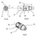
- FIGS. 5 and 6are schematic representations of a further embodiment of the device of the present invention, in which said uterine manipulator device I can be adapted to guide the surgeon who needs to carry out a hysterectomy, be it a total or sub-total hysterectomy. Consequently, the device I further comprises hysterectomy guide means, indicated by the general reference 42 comprises an adapter 43 comprising engagement means 44 to engage the proximal end 27 of the sealing abutment means 6, and ablation guide sleeve 45 which is adapted to engage at least partially circumferentially an exterior wall 46 of the cervix 7.
- hysterectomy guide meansindicated by the general reference 42 comprises an adapter 43 comprising engagement means 44 to engage the proximal end 27 of the sealing abutment means 6, and ablation guide sleeve 45 which is adapted to engage at least partially circumferentially an exterior wall 46 of the cervix 7.
- the adapter 43preferably has clip means 47 for removably engaging a proximal surface 48 of the sealing abutment means 6.
- the adapter 43has lands or cut-outs 49, which form wings 50 in the adapter 43 and enable it to be slid over the cone 28 via the distal end of the sealing abutment means 6. Since the adapter is preferably made of resilient or elastic material, the wings 50 spread as the adapter 43 is slid over the cone 28 towards the widened proximal end 29 of the latter.
- the clip means 47which can for example be one or more radial flanges 51 provided on the wings 50, then reach over the widened proximal end 29 of the cone and clip into place on a contact surface 48 which is essentially the proximal surface of the widened proximal end 29.
- a clipping actionprovides for sufficient maintainance of the adapter 43 in position, whilst at the same time allowing for its release simply by easing a radial flange back over onto the cone 28. Consequently, the adapter 43 is preferably substantially conical in shape, extending from a widened proximal end 52 towards a narrowed distal end 53, the shape defined thereby enabling sealing abutment of the adapter 43 with an inner vaginal wall 39.
- the ablation guide sleeve 45also comprises a peripheral projecting wall 54, which extends from a proximal end 55 in abutment with the distal end 53 of the adapter 43, towards a distal end 56, wherein the projecting wall 54 engages partially circumferentially an exterior wall of the cervix 46.
- the projecting wall 54serves to guide the surgeon wishing to remove the uterus 15 down to a limit on the cervix 7 that is defined by the extent of the projecting peripheral wall 54.
Landscapes
- Health & Medical Sciences (AREA)
- Surgery (AREA)
- Life Sciences & Earth Sciences (AREA)
- Biomedical Technology (AREA)
- Medical Informatics (AREA)
- Reproductive Health (AREA)
- Pregnancy & Childbirth (AREA)
- Engineering & Computer Science (AREA)
- Gynecology & Obstetrics (AREA)
- Heart & Thoracic Surgery (AREA)
- Nuclear Medicine, Radiotherapy & Molecular Imaging (AREA)
- Molecular Biology (AREA)
- Animal Behavior & Ethology (AREA)
- General Health & Medical Sciences (AREA)
- Public Health (AREA)
- Veterinary Medicine (AREA)
- Surgical Instruments (AREA)
Description
- The present invention relates to single use, disposable surgical instruments in general, and more particularly to a device for manipulating a uterus that is particularly adapted to use in coelioscopic surgery.
- One of the current problems encountered in coelioscopic surgery in female patients is the position that the female reproductive organs, and in particular the uterus, the fallopian tubes and ovaries, adopt because of the way the patient is laid out on the operating table. This position, know as the Trendelebourg position, causes the female reproductive organs to fall back into the Douglas' pouch or rectouterine excavation, thereby making access to that pouch difficult or impossible for the surgeon. Several attempts have been made to produce devices that would assist the surgeon in gaining access to the Douglas' pouch more easily, most of which involve inflicting some kind of trauma on the female reproductive organs.
- For example, one known device comprises a frustoconical screw-threaded plug that is screwed into the cervix of the female patient, in order to permit manipulation of the uterus, and thereby enable the surgeon to position the uterus as desired during surgery. The problem with a device such as this is that the screw thread bites into the cervical wall, and inevitably causes a certain degree of trauma. It has been noticed in general that trauma to the cervical wall, in whatever form, can lead to reduced fertility, especially in younger female subjects, and so it would be desirable to avoid, where possible, inflicting any such trauma.
- Another example of a device for uterine manipulation involves an inflatable balloon, that is provided at a distal tip of a manipulator. The manipulator is inserted into the uterus via the vagina, and the balloon inflated so that the exterior walls of the balloon come into pressure contact with the inner walls of the uterus. The idea is that the expansion of the balloon causes sufficient friction against the inner uterine wall to enable the surgeon to operate the manipulator and thereby displace the uterus in the desired direction. However, in order to be effective, the device must generally be inserted into the uterus until it meets with the upper inner wall of the latter, and then the balloon inflated, and the pressure thereby exerted by the balloon can cause localised damage to the uterine inner wall. Document
US 2,822,809 discloses do uterine manipulator according to the preamble ofindependent claim 1. - The device according to the present invention attempts to overcome the above limitations, whilst at the same time being easy to use and operate, and most notably, being atraumatic, i.e. not inflicting trauma on the inner wall of the uterus or the cervical wall.
- Accordingly, one object of the present invention is a single use, disposable uterine manipulator device, comprising :
- a tubular elongate portion defining a longitudinal axis of the device, and having a proximal and a distal extremity ;
- wherein the distal extremity is provided with sealing abutment means for sealingly abutting the cervix, and the distal extremity is further provided with uterine wall suction means distributed around the distal extremity for providing suction to the device, thereby enabling said device to come into suction contact with an inner uterine wall;
- Preferably, the tubular elongate portion is made of a sterilisable material, preferably stainless steel, however other materials may also provide satisfaction, provided that they are suitable for use in a surgical instrument, are suitably rigid and can be sterilised.
- Preferably, the sleeve of the uterine wall suction means is made of a sterilisable polymer material, and even more preferably of a polymer material selected from the group consisting of polyoxymethacrylate, polyacetal, and PA66.
- In accordance with a preferred embodiment, the tubular elongate portion is open at the distal extremity and together with an inner surface of the sleeve mentioned above defines a space allowing for the passage of fluid. The passage of fluid can be simply formed by providing for a difference in diameter between the outside diameter of the tubular elongate portion and the inner diameter of the sleeve, and leaving the distal extremity of the tubular elongate portion free or unblocked, such that fluids may pass either into the distal extremity of the elongate portion, for example, air being withdrawn under vacuum, or in the opposite direction, for example, when a liquid, such as a contrast or washing agent, is injected from the proximal end of the tubular elongate portion.
- The sleeve also preferably comprises a plurality of suction orifices which traverse a wall of the sleeve and communicate with the space allowing for passage of fluid. Thes plurality of orifices is even more preferably distributed about the sleeve in a manner enabling a sufficient portion of the sleeve to come into suction contact with an inner uterine wall. Thus the plurality of orifices forms, along with the space created between the sleeve and elongate tubular portion, a way of creating fluid communication between an inner wall of the uterus, and the outside environment, i.e. the environment outside of the uterus.
- Where fluid communication to be created is in the form of vacuum or suction, such suction is preferably provided at a vacuum pressure comprised between 0.4 bar and 0.8 bar, and most preferably is about 0.6 bar. The applicant has noticed that this latter value is completely atraumatic for the tissue of the uterus, including the inner walls of the uterus to which the device becomes attached when vacuum or suction is applied through the device.
- Even more preferably, the device sleeve comprises a total of 8, or most preferably 10 orifices, distributed evenly about the sleeve in a 3-2-3, or respectively, a 3-2-3-2 configuration. Such a configuration allows for optimal coverage of the inner uterine wall surfaces, thereby facilitating manipulation of the uterus when vacuum is being applied.
- The sealing abutment means are designed to abut, in a sealing manner, the cervix, and thus it is preferred that they be located at a proximal end of the sleeve, and have a section that is substantially conical, adapted in shape and size to sealingly abut a cervix, and extending from a widened proximal end to a narrowed distal end which abuts or adjoins the proximal end of the sleeve. It is to be noted that since the sealing abutment means are substantially conical, the nose or distal end formed thereby can preferably be snubbed or rounded, to enable a less traumatic contact with the cervix. One should note here the complete contrast with prior art solutions involving a screw thread which engages the tissue of the cervix and can cause damage thereto.
- In one advantageous embodiment, the device further preferably comprises grip means, mounted in axial sliding engagement around the tubular elongate portion, proximal to the uterine wall suction means and sealing abutment means, and distal to the proximal extremity of the tubular elongate portion. Preferably, the grip means are mounted in fixed rotating engagement about the tubular elongate portion, but they can also be made to rotate in and out of a locked position, should that be desired. It can thus be seen that the tubular elongate portion bearing the uterine wall suction means can slide along inside the grip means, while leaving an exterior grip surface free for the surgeon to manipulate the device, for example, rotating it in one direction or another.
- Even more preferably, the device also comprises a Luer lock 2-way valve located at the proximal extremity the tubular elongate portion. Such a 2-way Luer lock preferable provides :
- in a first open position, for a fluid communication between the elongate tubular portion and the uterine wall suction means,
- in a second position, for complete obstruction of the Luer lock.
- In still yet another preferred embodiment, a surgical kit comprising the above mentioned uterine manipulator device in combination with an hysterectomy guide means. These guide means are used to aid the surgeon in performing a hysterectomy, either a sub-total hysterectomy or a total hysterectomy, depending on how much of the cervix is removed along with the uterus. Preferably, the hysterectomy guide means comprises an adapter comprising engagement means to engage the proximal end of the sealing abutment means, and ablation guide sleeve which is adapted to engage at least partially circumferentially an exterior wall of the cervix. Even more preferably, the adapter has clips means for removably engaging a proximal surface of the sealing abutment means. It can thus be seen that the adapter slides over the sealing abutment means and can be clipped and retained at a proximal end of the sealing abutment means. Where the adapter is made of resilient or slightly elastic material, it is preferably designed to elastically fit over the substantially conical sealing abutment means and then snap back over a proximal circumference or periphery of said sealing abutment means.
- As a result, it is preferred that the adapter also be substantially conical in shape, extending from a widened proximal end towards a narrowed distal end, the shape defined thereby enabling sealing abutment of the adapter with an inner vaginal wall. Thus, the initial cervical sealing abutment means no longer serve their purpose, since they are covered, in this particular embodiment, by the adapter, which is dimensioned to provide sealing abutment with an inner vaginal wall and not the cervix.
- In a further preferred embodiment, the ablation guide sleeve is substantially tubular, in order to be able to be slid over the device as described initially, but also comprises a peripheral projecting wall, which extends from a proximal end in abutment with the distal end of the adapter, towards a distal end, wherein the projecting wall engages at partially circumferentially an exterior wall of the cervix. In this way, the projecting wall serves as a guide for the surgeon as to where the tissue of the cervix should be sectioned and removed along with the rest of the uterus.
- Other objects and preferred embodiments will become apparent through the detailed description and the figures, given purely for illustrative purposes, as follows :
Figure 1 is schematic represenation of a single use, disposable, uterine manipulation device according to the present invention ;Figure 2a, 2b and 2c are different schematic views of a distal part of the uterine manipulation device illustrated inFigure 1 ;Figure 3 is a first representation of the introduction into a uterus of the device ofFigure 1 ;Figure 4 is a second representation of the normal final position of the device ofFigure 1 once fully introduced into the uterus ;Figures 5a, 5b and 5c are different schematic representations of a further adapter for the device of the present invention ;Figure 6 is a schematic representation of an extra component that fits onto the adapter illustrated inFigure 5 , and which is suited to assisting a surgeon in carrying out a hysterectomy.- As can be seen from
Figure 1 , the single use, disposable, uterine manipulation device, indicated by the general reference I, comprises a tubular elongate portion, identified by thegeneral reference 2, defining alongitudinal axis 3 of the device I, and having a proximal 4 and adistal extremity 5. Thedistal extremity 5 is provided with sealing abutment means, indicated generally by thereference 6, for sealingly abutting a cervix 7 (cf.Figures 3 and4 ), and thedistal extremity 5 is further provided with uterine wall suction means 8 distributed around thedistal extremity 5 for providing suction to the device I, thereby enabling the device I to come into suction contact with aninner uterine wall 9. The tubularelongate portion 2 is made of a sterilisable, surgically appropriate material, preferably stainless steel, and thus generally takes the shape of astainless steel tube 10. Thetube 10 is essentially hollow along theaxis 3 and has an opening at both the proximal 4 and distal 5 extremities.Figure 1 also shows that the device I further comprises grip means, indicated generally by thereference 11, mounted in axial sliding engagement around the tubularelongate portion 2, proximal to the uterine wall suction means 8 and sealing abutment means 6 and distal to theproximal extremity 4 of the tubularelongate portion 2. The grip means 11 are mounted in fixed rotating engagement about the tubularelongate portion 2. As can be seen fromFigure 1 , the grip means 11 comprise a fairly largeouter diameter tube 12. The tube can optionally be provided with ridges, not illustrated in the figure, to facilitate prehension by the operator of thedevice 1. The grip means 11 further include an enlarged, approximately funnel-shaped,proximal extremity 13, enabling other instruments to be introduced into thetube 12 if necessary. Since the grip means 11 are rotatively, but notslidingly locked, about theaxis 3 of the device, it is posssible to manipulate the device by rotating thetube 12 about said axis. It is furthermore possible to slide the sealing abutment means 6 and uterine wall suction means 8 along theaxis 3 to introduce the latter into, and out of, thevagina 14 towards theuterus 15. Theproximal extremity 4 of the device I is connected to afluid communication conduit 16. Theconduit 16 is made of a flexible fluid impermeable polymer material, of the type commonly used in hospitals or other surgical devices for the passage of fluids, be they liquids or gases. Thefluid communication conduit 16 is connected to aLuer lock valve 17, having twoports first port 18 is connected to a vacuum generator device or apparatus (not shown), for establishing vacuum or suction, such that air is sucked in via the uterine wall suction means 8, through thedistal extremity 5 of the device I, and then along the tubularelongate portion 2 and through theconduit 16 andfirst port 18. Asecond port 19 is provided for introduction and removal of another fluid, for example, a contrast agent such as methylene blue, which can be injected as a liquid through thesecond port 19 and into theuterus 15 via the device I by following the same schema as above, but in a reverse direction. The 2-wayLuer lock valve 17 thus provides, in a first open position, for a fluid communication between the elongatetubular portion 2 and the uterine wall suction means 8, and in a second position, for complete obstruction of theLuer lock 17. The 2Luer lock valve 17 thus also comprises a switch orlever 20, which can be activated to set the lock in a desired position, depending on whether the operator of the device I wants the fluid communication to be vacuum or suction in the first case, fluid communication for the introduction of a contrast agent, in a second case, and of course a third position, whereby all fluid communication is obstructed. In order to facilitate recognition of the position in which thelock 17 is set, the lock can be provided withmarkings 21, arranged on thelever 20, and indexed therewith. - As can be seen in more detail from
Figure 2 , the sealing abutment means 6 and the uterine wall suction means 8 are formed integrally as asleeve 32 that fits over thedistal extremity 5 of the tubularelongate portion 2.Figure 2a shows a cross-section of thesleeve 32, alongaxis 3 of the device, clearly showing that the sleeve is hollow, and has anouter wall 22 andinner wall 23, defining an inner bore orspace 24. Thedistal end 25 of the sleeve is blind, i.e. closed, and thedistal limit 26 of the bore orspace 24 has a generally concave shape, such that a distal end of thestainless steel tube 10 does not sealingly abut saidlimit 26, thereby allowing for passage of fluid between an opening in the distal end of thetube 10, and thespace 24 of the sleeve. Additionally, as can be seen fromFigure 2b , the sleeve does not have a circular cross-section, but extends fromproximal end 27 towards thedistal end 25 of the sleeve in a slightly widening cross-section, thereby ensuring that afluid communication space 24 will be created between thestainless steel tube 10 and theinner wall 23 of thesleeve 32, and that thetube 10 will be held in elastic sealing engagement with theproximal end 27. The sealing abutment means 6 are located at aproximal end 27 of thesleeve 32, and has a cross-section susbtantially forming acone 28, adapted in shape and size to sealingly abut a cervix. Thecone 28 extends from a widenedproximal end 29 to a narroweddistal end 30 which abuts or adjoins thesleeve 32. The uterine wall suction means 8 also comprise a plurality oforifices 31, distributed evenly around thesleeve 32, preferably in a 3-2-3-2 configuration or arrangement, as can be seen partially fromFigure 2c . Theorifices 31 traverse the outer andinner walls fluid communication space 24. Thus, when vacuum is applied via theLuer lock port 18, air is withdrawn from within the device and a depression created that causes auterine wall 9 to be sucked onto thesleeve 32. In a converse manner, when fluid, such as a contrast agent, is introduced viaport 19, said fluid can pass through the device, into thespace 24 and through the orifices into theuterus 15. As the cone sealingly abuts thecervix 7 of theuterus 15, no leakage in the sealtight environment can occur, and thus the vacuum pressure is maintained, or respectively, the fluid introduced into theuterus 15 remains therein or will permeate through the tissues therein or other organs connected thereto. - Turning now to
Figure 3 , one can see a schematic representation of female human reproductive organs, indicated by thegeneral reference 33. These organs are represented generally by theovaries fallopian tubes uterine cavity 38, thecervix 7, theuterine isthmus 40, and thevagina 14. Thevagina 14 and uterus are shown here o the right hand side a in partial cut-away representation, in order to show theuterine cavity 38 and inner 39 and outer vaginal 41 walls andinner uterine 9 walls. InFigure 3 , one can see that the device has been introduced via thevagina 14 and the cervix into theuterus 38, such that thedistal end 25 of thesleeve 32 has reached theuterine isthmus 40. In this position, the device I of the invention is not yet ready for use. Figure 4 shows, in a schematic representation, the position of the device I of the invention, once introduction thereof into theuterus 15 has been completed. In this figure, it can be seen that thedistal end 30 of thecone 28 of the sealing abutment means has come into sealing abutment engagement with thecervix 7, forming a substantially leaktight seal. One will also note that thesleeve 32 has now been pushed past theuterine isthmus 40, such that thedistal end 25 of thesleeve 32 is located in theuterine cavity 38. The plurality oforifices 31 of the suction means 8 are now in physical contact with an inner uterine wall 9.InFigure 4 , theLuer lock port 18 is shown in the closed position, but when thelever 20 is moved and set to the open position, i.e. in this particular example by turning the lever through 90 degrees so that it lies over thesecond port 19, then vacuum pressure that can be applied will suck out any air in the device, creating a depression in thespace 24 between the inner wall of thesleeve 32 and stainless steel tube and thereby causing a drop in pressure at theorifices 31, which in turn will cause the inneruterine wall 9 to be sucked onto theouter wall 22 of thesleeve 32. It thus becomes possible to manipulate theuterus 15 and associated organs and put them into a position more suitable for the surgeon, simply by moving the device around in the three-dimensional anatomical space. In this way, it also makes the Douglas' pouch accessible to the surgeon, should that be required. The seal is maintained by the conical shape of thecone 28 which abuts sealingly against thecervix 7, independently of the angle of inclination of the device. In a similar maner, a diagnostic test, for example, the methylene blue test, can be carried out very simply by activating thelever 20 again, to set theLuer lock port 18 into the closed position, for example, by either moving thelever 20 forward again by 90 degrees, or by reversing the initial movement. This movement will then openport 19, through which the methylen blue contrast agent can be injected. As there is a leaktight seal against thecervix 7, none of the fluid introduced can escape and will therefore diffuse in a classical manner through the various tissues, and particularly up the fallopian tubes to the ovaries, where the contrast agent will become visible through a coelioscope.- Turning now to
Figures 5 and6 , these are schematic representations of a further embodiment of the device of the present invention, in which said uterine manipulator device I can be adapted to guide the surgeon who needs to carry out a hysterectomy, be it a total or sub-total hysterectomy. Consequently, the device I further comprises hysterectomy guide means, indicated by thegeneral reference 42 comprises anadapter 43 comprising engagement means 44 to engage theproximal end 27 of the sealing abutment means 6, and ablation guidesleeve 45 which is adapted to engage at least partially circumferentially anexterior wall 46 of thecervix 7. Theadapter 43 preferably has clip means 47 for removably engaging a proximal surface 48 of the sealing abutment means 6. InFigure 5 , it can be seen that theadapter 43 has lands or cut-outs 49, which formwings 50 in theadapter 43 and enable it to be slid over thecone 28 via the distal end of the sealing abutment means 6. Since the adapter is preferably made of resilient or elastic material, thewings 50 spread as theadapter 43 is slid over thecone 28 towards the widenedproximal end 29 of the latter. The clip means 47, which can for example be one or moreradial flanges 51 provided on thewings 50, then reach over the widenedproximal end 29 of the cone and clip into place on a contact surface 48 which is essentially the proximal surface of the widenedproximal end 29. Such a clipping action provides for sufficient maintainance of theadapter 43 in position, whilst at the same time allowing for its release simply by easing a radial flange back over onto thecone 28. Consequently, theadapter 43 is preferably substantially conical in shape, extending from a widenedproximal end 52 towards a narroweddistal end 53, the shape defined thereby enabling sealing abutment of theadapter 43 with an innervaginal wall 39. Theablation guide sleeve 45 also comprises a peripheral projectingwall 54, which extends from aproximal end 55 in abutment with thedistal end 53 of theadapter 43, towards adistal end 56, wherein the projectingwall 54 engages partially circumferentially an exterior wall of thecervix 46. In this way, the projectingwall 54 serves to guide the surgeon wishing to remove theuterus 15 down to a limit on thecervix 7 that is defined by the extent of the projectingperipheral wall 54.
wherein the sleeve can preferably have a section that widens from a proximal end towards a distal end of said sleeve.
Claims (18)
- Single use, disposable, uterine manipulator device (1) comprising :- a tubular elongate portion (2) defining a longitudinal axis (3) of the device, and having a proximal (4) and a distal (5) extremity ;- wherein the distal extremity (5) is provided with sealing abutment means (6) for sealingly abutting a cervix, and the distal extremity (5) is further provided with uterine wall suction means (8) distributed around the distal extremity (5) for providing suction to the device, thereby enabling said device (1) to come into suction contact with an inner uterine wall; and- wherein the sealing abutment means (6) and the uterine wall suction means (8) are formed integrally as a sleeve (32) that fits over the distal extremity (5) of the tubular elongate portion (2),characterised in thatthe sleeve (32) has a cross-section that widens from a proximal end (27) towards a distal (25) end of said sleeve.
- Uterine manipulator device according to claim 1, wherein the tubular elongate portion (2) is made of a sterilisable material, preferably stainless steel.
- Uterine manipulator device according to claim 1, wherein the sleeve (32) is made of a sterilisable polymer material, preferably selected from the group consisting of polyoxymethacrylate, polyacetal, and PA66.
- Uterine manipulator device according to any of claims 1 to 3, wherein the tubular elongate portions (2) is open at the distal extremity (5) and together with an inner surface (23) of the sleeve (32) defines a space allowing for the passage of fluid.
- Uterine manipulator device according to any of the preceding claims, wherein the sleeve (32) comprises a plurality of suction orifices (31) which traverse a wall of the sleeve (32) and communicate with the space allowing for passage of fluid.
- Uterine manipulator device according to claim 5, wherein the plurality of orifices (31) is distributed about the sleeve (32) in a manner enabling a sufficient portion of the sleeve (32) to come into suction contact with an inner uterine wall.
- Uterine manipulator device according to any of the preceding claims, wherein the suction is provided at a vacuum pressure comprised between 0.4 bar and 0.8 bar, and preferably is about 0.6 bar.
- Uterine manipulator device according to any of the preceding claims, wherein the sleeve (32) comprises a total of 8 orifices (31), distributed evenly about the sleeve in a 3-2-3 configuration, or even more preferably 10 orifices (31), distributed evenly about the sleeve (32) in a 3-2-3-2 configuration.
- Uterine manipulator device according to any of the preceding claims, wherein the sealing abutment means (6) are located at a proximal end of the sleeve (32), and has a section that is substantially conical, adapted in shape and size to sealingly abut a cervix, and extending from a widened proximal end (29) to a narrowed distal end (30) which abuts or adjoins the sleeve (32)
- Uterine manipulator device according to any of the preceding claims, wherein the device further comprises grip means (11), mounted in axial sliding engagement around the tubular elongate portion (2), proximal to the uterine wall suction means (8) and sealing abutment means (6) and distal to the proximal extremity (4) of the tubular elongate portion (2).
- Uterine manipulator device according to any of the preceding claims, wherein the grip means (11) are mounted in fixed rotating engagement about the tubular elongate portion (21).
- Uterine manipulator device according to any of the preceding claims, wherein the device further comprises a Luer lock 2-way valve (17) located at the proximal extremity (4) of the tubular elongate portion (2).
- Uterine manipulator device according to claim 12, wherein the 2-way Luer lock (17) provides :- in a first open position, for a fluid communication between the elongate tubular (2) portion and the uterine wall suction means (8),- in a second position, for complete obstruction of the Luer lock.
- Surgical kit comprising a uterine manipulator device according to any of the preceding claims, and a hysterectomy guide means (42).
- Surgical kit according to preceding claim 14, wherein the hysterectomy guide means (42) comprises an adapter (43) comprising engagement means (44) to engage the proximal end (27) of the sealing abutment means (6), and ablation guide sleeve (45) which is adapted to engage at least partially circumferentially an exterior wall of the cervix.
- Surgical kit according to preceding claim 15, wherein the adapter (43) has clips means (47) for removably engaging a proximal surface (48) of the sealing abutment means (6).
- Surgical kit according to preceding claim 15, wherein the adapter (43) is substantially conical in shape, extending from a widened proximal end (52) towards a narrowed distal end (53), the shape defined thereby enabling sealing abutment of the adapter (43) with an inner vaginal wall.
- Surgical kit according to preceding claims 17, wherein the ablation guide sleeve (45) comprises a peripheral projecting wall (54), which extends from a proximal end (55) in abutment with the distal end (53) of the adapter (43) towards a distal end (56), wherein the projecting wall (54) engages partially circumferentially an exterior wall of the cervix.
Applications Claiming Priority (1)
| Application Number | Priority Date | Filing Date | Title |
|---|---|---|---|
| PCT/IB2007/004428WO2009074844A1 (en) | 2007-12-12 | 2007-12-12 | Single use, disposable, uterine manipulator and method of use |
Publications (2)
| Publication Number | Publication Date |
|---|---|
| EP2231040A1 EP2231040A1 (en) | 2010-09-29 |
| EP2231040B1true EP2231040B1 (en) | 2014-04-09 |
Family
ID=39512700
Family Applications (1)
| Application Number | Title | Priority Date | Filing Date |
|---|---|---|---|
| EP07870457.4AActiveEP2231040B1 (en) | 2007-12-12 | 2007-12-12 | Single use, disposable, uterine manipulator |
Country Status (4)
| Country | Link |
|---|---|
| US (1) | US20100274260A1 (en) |
| EP (1) | EP2231040B1 (en) |
| CA (1) | CA2709080A1 (en) |
| WO (1) | WO2009074844A1 (en) |
Families Citing this family (27)
| Publication number | Priority date | Publication date | Assignee | Title |
|---|---|---|---|---|
| US10695126B2 (en) | 2008-10-06 | 2020-06-30 | Santa Anna Tech Llc | Catheter with a double balloon structure to generate and apply a heated ablative zone to tissue |
| US9700365B2 (en) | 2008-10-06 | 2017-07-11 | Santa Anna Tech Llc | Method and apparatus for the ablation of gastrointestinal tissue |
| US9561068B2 (en) | 2008-10-06 | 2017-02-07 | Virender K. Sharma | Method and apparatus for tissue ablation |
| US10064697B2 (en) | 2008-10-06 | 2018-09-04 | Santa Anna Tech Llc | Vapor based ablation system for treating various indications |
| US9561066B2 (en)* | 2008-10-06 | 2017-02-07 | Virender K. Sharma | Method and apparatus for tissue ablation |
| CN103209663B (en) | 2010-10-18 | 2016-08-10 | 碧奥塞普蒂夫股份有限公司 | For device or medicine are inserted endoceliac method and apparatus |
| USD653338S1 (en)* | 2010-11-15 | 2012-01-31 | Karl Storz Gmbh & Co. Kg | Uterine manipulator |
| US8608738B2 (en) | 2010-12-06 | 2013-12-17 | Soulor Surgical, Inc. | Apparatus for treating a portion of a reproductive system and related methods of use |
| US9987042B2 (en) | 2011-04-07 | 2018-06-05 | Jai Singh | General uterine manipulator and system |
| US20130197536A1 (en)* | 2011-04-07 | 2013-08-01 | Jai Singh | General uterine manipulator and system |
| CN203647441U (en) | 2011-04-07 | 2014-06-18 | 基万·史蒂文·辛格 | Uterine Manipulator System |
| US12076047B2 (en)* | 2012-03-15 | 2024-09-03 | Alydia Health, Inc. | Uterine hemorrhage controlling system and method |
| US10064651B2 (en) | 2012-03-15 | 2018-09-04 | Inpress Technologies, Inc. | Uterine hemorrhage controlling system and method |
| US20130269705A1 (en) | 2012-04-16 | 2013-10-17 | Thomas C. Kochem | Variable stiffness flexure |
| AU2013249076B2 (en) | 2012-04-20 | 2018-03-29 | Jai Singh | Repositionable medical instrument support systems, devices, and methods |
| US9089365B2 (en) | 2012-04-26 | 2015-07-28 | Imds Llc | Tissue fixation device |
| USD750260S1 (en)* | 2012-09-21 | 2016-02-23 | Lsi Solutions, Inc. | Handheld uterine sound device |
| US20140200591A1 (en)* | 2013-01-11 | 2014-07-17 | Hologic, Inc. | Cervical sealing apparatus |
| EP3964151A3 (en) | 2013-01-17 | 2022-03-30 | Virender K. Sharma | Apparatus for tissue ablation |
| US9333111B2 (en) | 2013-02-04 | 2016-05-10 | Hologic, Inc. | Fundus bumper mechanical reference for easier mechanism deployment |
| US9895192B2 (en) | 2013-03-13 | 2018-02-20 | Hologic, Inc. | Intrauterine treatment device with articulating array |
| WO2017173232A1 (en)* | 2016-04-01 | 2017-10-05 | Langell John Thomas | Uterine contraction device |
| US12364537B2 (en) | 2016-05-02 | 2025-07-22 | Santa Anna Tech Llc | Catheter with a double balloon structure to generate and apply a heated ablative zone to tissue |
| US11331140B2 (en) | 2016-05-19 | 2022-05-17 | Aqua Heart, Inc. | Heated vapor ablation systems and methods for treating cardiac conditions |
| EP3801324B1 (en) | 2018-06-01 | 2025-05-28 | Aqua Medical, Inc. | Vapor generation and delivery systems |
| EP3763341A1 (en)* | 2019-07-11 | 2021-01-13 | National University of Ireland, Galway | A device for treating vaginal atrophy |
| US11839408B2 (en)* | 2022-04-06 | 2023-12-12 | Lucie Medical Inc. | Systems, devices, and methods for uterine hemostasis |
Family Cites Families (9)
| Publication number | Priority date | Publication date | Assignee | Title |
|---|---|---|---|---|
| US1245845A (en)* | 1915-07-13 | 1917-11-06 | Herbert Spencer White | Surgical instrument. |
| US2400251A (en)* | 1943-07-29 | 1946-05-14 | Charles E Nagel | Gynecological instrument |
| US2822809A (en)* | 1952-09-30 | 1958-02-11 | Kidde Mfg Co Inc | Tip for uterine cannula |
| BE786542A (en)* | 1971-07-22 | 1973-01-22 | Dow Corning | SUCTION DEVICE ALLOWING TO OBTAIN CELL SAMPLES |
| US3777743A (en)* | 1972-09-29 | 1973-12-11 | Kendall & Co | Endometrial sampler |
| DE4114311A1 (en)* | 1991-05-02 | 1992-11-12 | Harald Heidmueller | EXTRACTOR |
| US5643285A (en)* | 1994-10-18 | 1997-07-01 | Blairden Precision Instruments, Inc. | Vaginal extender for colpotomy surgery |
| DE19603981C2 (en)* | 1996-02-05 | 1998-11-05 | Wolf Gmbh Richard | Medical instrument for uterine manipulation |
| FR2745171B1 (en)* | 1996-02-26 | 1998-05-22 | Hourcabie Jacques Alain | SURGICAL INSTRUMENT FOR PERELELOSCOPIC HYSTERECTOMY |
- 2007
- 2007-12-12USUS12/747,240patent/US20100274260A1/ennot_activeAbandoned
- 2007-12-12CACA2709080Apatent/CA2709080A1/ennot_activeAbandoned
- 2007-12-12EPEP07870457.4Apatent/EP2231040B1/enactiveActive
- 2007-12-12WOPCT/IB2007/004428patent/WO2009074844A1/enactiveApplication Filing
Also Published As
| Publication number | Publication date |
|---|---|
| CA2709080A1 (en) | 2009-06-18 |
| EP2231040A1 (en) | 2010-09-29 |
| US20100274260A1 (en) | 2010-10-28 |
| WO2009074844A1 (en) | 2009-06-18 |
Similar Documents
| Publication | Publication Date | Title |
|---|---|---|
| EP2231040B1 (en) | Single use, disposable, uterine manipulator | |
| US8740916B2 (en) | Uterine manipulator assemblies and related components and methods | |
| US5295952A (en) | Swab for laparoscopy | |
| US5197948A (en) | Intra-abdominal organ manipulator, irrigator and aspirator | |
| US5630797A (en) | Everting catheter system and method of utilizing the same | |
| US20240252209A1 (en) | Apparatus and method for everting catheter for embryo transfer using transvaginal ultrasound | |
| US5823940A (en) | Optical surgical device for examining genitourinary tissue | |
| EP2116202B1 (en) | Uterine manipulator for complete removal of human uteri | |
| US5855549A (en) | Method of using an optical female urethroscope | |
| US8292901B2 (en) | Uterine manipulators and related components and methods | |
| US5569288A (en) | Safety penetrating instrument | |
| US8118736B2 (en) | Method of accessing a bladder and associated apparatus therefor | |
| US5980534A (en) | Cervical clamp | |
| EP4101405B1 (en) | Natural orifice surgery system | |
| US2256942A (en) | Surgical instrument | |
| JP7738040B2 (en) | Apparatus and method for eversion catheter for IUD delivery and placement in the uterine cavity | |
| US20120109147A1 (en) | Uterine Manipulators and Related Components and Methods | |
| WO2004082486A1 (en) | Apparatus and method for colonoscopic appendectomy | |
| JPH04226620A (en) | Surgical trocar | |
| EP3263067B9 (en) | Device for inserting in or obtaining a fluid with gametes, embryos or any other type of solution from the oviduct of a sow | |
| JPH0397469A (en) | Instrument for access to uterus | |
| EP0642800A1 (en) | Irrigation probe assembly | |
| US5256139A (en) | Intra-abdominal organ manipulator, irrigator, aspirator and method | |
| WO1987005523A1 (en) | Tubular devices for introduction into body orifices | |
| US5697911A (en) | Plug for a wound drain |
Legal Events
| Date | Code | Title | Description |
|---|---|---|---|
| PUAI | Public reference made under article 153(3) epc to a published international application that has entered the european phase | Free format text:ORIGINAL CODE: 0009012 | |
| 17P | Request for examination filed | Effective date:20100712 | |
| AK | Designated contracting states | Kind code of ref document:A1 Designated state(s):AT BE BG CH CY CZ DE DK EE ES FI FR GB GR HU IE IS IT LI LT LU LV MC MT NL PL PT RO SE SI SK TR | |
| AX | Request for extension of the european patent | Extension state:AL BA HR MK RS | |
| 17Q | First examination report despatched | Effective date:20111208 | |
| GRAP | Despatch of communication of intention to grant a patent | Free format text:ORIGINAL CODE: EPIDOSNIGR1 | |
| INTG | Intention to grant announced | Effective date:20131017 | |
| GRAS | Grant fee paid | Free format text:ORIGINAL CODE: EPIDOSNIGR3 | |
| GRAA | (expected) grant | Free format text:ORIGINAL CODE: 0009210 | |
| AK | Designated contracting states | Kind code of ref document:B1 Designated state(s):AT BE BG CH CY CZ DE DK EE ES FI FR GB GR HU IE IS IT LI LT LU LV MC MT NL PL PT RO SE SI SK TR | |
| AX | Request for extension of the european patent | Extension state:AL BA HR MK RS | |
| REG | Reference to a national code | Ref country code:GB Ref legal event code:FG4D | |
| REG | Reference to a national code | Ref country code:AT Ref legal event code:REF Ref document number:660879 Country of ref document:AT Kind code of ref document:T Effective date:20140415 Ref country code:CH Ref legal event code:EP | |
| REG | Reference to a national code | Ref country code:IE Ref legal event code:FG4D | |
| REG | Reference to a national code | Ref country code:DE Ref legal event code:R096 Ref document number:602007036077 Country of ref document:DE Effective date:20140522 | |
| REG | Reference to a national code | Ref country code:AT Ref legal event code:MK05 Ref document number:660879 Country of ref document:AT Kind code of ref document:T Effective date:20140409 | |
| REG | Reference to a national code | Ref country code:NL Ref legal event code:VDEP Effective date:20140409 | |
| REG | Reference to a national code | Ref country code:LT Ref legal event code:MG4D | |
| PG25 | Lapsed in a contracting state [announced via postgrant information from national office to epo] | Ref country code:GR Free format text:LAPSE BECAUSE OF FAILURE TO SUBMIT A TRANSLATION OF THE DESCRIPTION OR TO PAY THE FEE WITHIN THE PRESCRIBED TIME-LIMIT Effective date:20140710 Ref country code:FI Free format text:LAPSE BECAUSE OF FAILURE TO SUBMIT A TRANSLATION OF THE DESCRIPTION OR TO PAY THE FEE WITHIN THE PRESCRIBED TIME-LIMIT Effective date:20140409 Ref country code:NL Free format text:LAPSE BECAUSE OF FAILURE TO SUBMIT A TRANSLATION OF THE DESCRIPTION OR TO PAY THE FEE WITHIN THE PRESCRIBED TIME-LIMIT Effective date:20140409 Ref country code:BG Free format text:LAPSE BECAUSE OF FAILURE TO SUBMIT A TRANSLATION OF THE DESCRIPTION OR TO PAY THE FEE WITHIN THE PRESCRIBED TIME-LIMIT Effective date:20140709 Ref country code:IS Free format text:LAPSE BECAUSE OF FAILURE TO SUBMIT A TRANSLATION OF THE DESCRIPTION OR TO PAY THE FEE WITHIN THE PRESCRIBED TIME-LIMIT Effective date:20140809 Ref country code:LT Free format text:LAPSE BECAUSE OF FAILURE TO SUBMIT A TRANSLATION OF THE DESCRIPTION OR TO PAY THE FEE WITHIN THE PRESCRIBED TIME-LIMIT Effective date:20140409 | |
| PG25 | Lapsed in a contracting state [announced via postgrant information from national office to epo] | Ref country code:AT Free format text:LAPSE BECAUSE OF FAILURE TO SUBMIT A TRANSLATION OF THE DESCRIPTION OR TO PAY THE FEE WITHIN THE PRESCRIBED TIME-LIMIT Effective date:20140409 Ref country code:PL Free format text:LAPSE BECAUSE OF FAILURE TO SUBMIT A TRANSLATION OF THE DESCRIPTION OR TO PAY THE FEE WITHIN THE PRESCRIBED TIME-LIMIT Effective date:20140409 Ref country code:LV Free format text:LAPSE BECAUSE OF FAILURE TO SUBMIT A TRANSLATION OF THE DESCRIPTION OR TO PAY THE FEE WITHIN THE PRESCRIBED TIME-LIMIT Effective date:20140409 Ref country code:SE Free format text:LAPSE BECAUSE OF FAILURE TO SUBMIT A TRANSLATION OF THE DESCRIPTION OR TO PAY THE FEE WITHIN THE PRESCRIBED TIME-LIMIT Effective date:20140409 Ref country code:ES Free format text:LAPSE BECAUSE OF FAILURE TO SUBMIT A TRANSLATION OF THE DESCRIPTION OR TO PAY THE FEE WITHIN THE PRESCRIBED TIME-LIMIT Effective date:20140409 | |
| PG25 | Lapsed in a contracting state [announced via postgrant information from national office to epo] | Ref country code:PT Free format text:LAPSE BECAUSE OF FAILURE TO SUBMIT A TRANSLATION OF THE DESCRIPTION OR TO PAY THE FEE WITHIN THE PRESCRIBED TIME-LIMIT Effective date:20140811 | |
| REG | Reference to a national code | Ref country code:DE Ref legal event code:R097 Ref document number:602007036077 Country of ref document:DE | |
| PG25 | Lapsed in a contracting state [announced via postgrant information from national office to epo] | Ref country code:DK Free format text:LAPSE BECAUSE OF FAILURE TO SUBMIT A TRANSLATION OF THE DESCRIPTION OR TO PAY THE FEE WITHIN THE PRESCRIBED TIME-LIMIT Effective date:20140409 Ref country code:CZ Free format text:LAPSE BECAUSE OF FAILURE TO SUBMIT A TRANSLATION OF THE DESCRIPTION OR TO PAY THE FEE WITHIN THE PRESCRIBED TIME-LIMIT Effective date:20140409 Ref country code:EE Free format text:LAPSE BECAUSE OF FAILURE TO SUBMIT A TRANSLATION OF THE DESCRIPTION OR TO PAY THE FEE WITHIN THE PRESCRIBED TIME-LIMIT Effective date:20140409 Ref country code:RO Free format text:LAPSE BECAUSE OF FAILURE TO SUBMIT A TRANSLATION OF THE DESCRIPTION OR TO PAY THE FEE WITHIN THE PRESCRIBED TIME-LIMIT Effective date:20140409 Ref country code:SK Free format text:LAPSE BECAUSE OF FAILURE TO SUBMIT A TRANSLATION OF THE DESCRIPTION OR TO PAY THE FEE WITHIN THE PRESCRIBED TIME-LIMIT Effective date:20140409 Ref country code:BE Free format text:LAPSE BECAUSE OF FAILURE TO SUBMIT A TRANSLATION OF THE DESCRIPTION OR TO PAY THE FEE WITHIN THE PRESCRIBED TIME-LIMIT Effective date:20140409 | |
| PLBE | No opposition filed within time limit | Free format text:ORIGINAL CODE: 0009261 | |
| STAA | Information on the status of an ep patent application or granted ep patent | Free format text:STATUS: NO OPPOSITION FILED WITHIN TIME LIMIT | |
| 26N | No opposition filed | Effective date:20150112 | |
| PG25 | Lapsed in a contracting state [announced via postgrant information from national office to epo] | Ref country code:IT Free format text:LAPSE BECAUSE OF FAILURE TO SUBMIT A TRANSLATION OF THE DESCRIPTION OR TO PAY THE FEE WITHIN THE PRESCRIBED TIME-LIMIT Effective date:20140409 | |
| REG | Reference to a national code | Ref country code:DE Ref legal event code:R097 Ref document number:602007036077 Country of ref document:DE Effective date:20150112 | |
| REG | Reference to a national code | Ref country code:DE Ref legal event code:R119 Ref document number:602007036077 Country of ref document:DE | |
| PG25 | Lapsed in a contracting state [announced via postgrant information from national office to epo] | Ref country code:LU Free format text:LAPSE BECAUSE OF FAILURE TO SUBMIT A TRANSLATION OF THE DESCRIPTION OR TO PAY THE FEE WITHIN THE PRESCRIBED TIME-LIMIT Effective date:20141212 Ref country code:SI Free format text:LAPSE BECAUSE OF FAILURE TO SUBMIT A TRANSLATION OF THE DESCRIPTION OR TO PAY THE FEE WITHIN THE PRESCRIBED TIME-LIMIT Effective date:20140409 | |
| REG | Reference to a national code | Ref country code:CH Ref legal event code:PL | |
| GBPC | Gb: european patent ceased through non-payment of renewal fee | Effective date:20141212 | |
| REG | Reference to a national code | Ref country code:IE Ref legal event code:MM4A | |
| REG | Reference to a national code | Ref country code:FR Ref legal event code:ST Effective date:20150831 | |
| PG25 | Lapsed in a contracting state [announced via postgrant information from national office to epo] | Ref country code:CH Free format text:LAPSE BECAUSE OF NON-PAYMENT OF DUE FEES Effective date:20141231 Ref country code:IE Free format text:LAPSE BECAUSE OF NON-PAYMENT OF DUE FEES Effective date:20141212 Ref country code:GB Free format text:LAPSE BECAUSE OF NON-PAYMENT OF DUE FEES Effective date:20141212 Ref country code:DE Free format text:LAPSE BECAUSE OF NON-PAYMENT OF DUE FEES Effective date:20150701 Ref country code:LI Free format text:LAPSE BECAUSE OF NON-PAYMENT OF DUE FEES Effective date:20141231 | |
| PG25 | Lapsed in a contracting state [announced via postgrant information from national office to epo] | Ref country code:FR Free format text:LAPSE BECAUSE OF NON-PAYMENT OF DUE FEES Effective date:20141231 | |
| PG25 | Lapsed in a contracting state [announced via postgrant information from national office to epo] | Ref country code:MC Free format text:LAPSE BECAUSE OF FAILURE TO SUBMIT A TRANSLATION OF THE DESCRIPTION OR TO PAY THE FEE WITHIN THE PRESCRIBED TIME-LIMIT Effective date:20140409 | |
| PG25 | Lapsed in a contracting state [announced via postgrant information from national office to epo] | Ref country code:CY Free format text:LAPSE BECAUSE OF FAILURE TO SUBMIT A TRANSLATION OF THE DESCRIPTION OR TO PAY THE FEE WITHIN THE PRESCRIBED TIME-LIMIT Effective date:20140409 | |
| PG25 | Lapsed in a contracting state [announced via postgrant information from national office to epo] | Ref country code:HU Free format text:LAPSE BECAUSE OF FAILURE TO SUBMIT A TRANSLATION OF THE DESCRIPTION OR TO PAY THE FEE WITHIN THE PRESCRIBED TIME-LIMIT; INVALID AB INITIO Effective date:20071212 Ref country code:TR Free format text:LAPSE BECAUSE OF FAILURE TO SUBMIT A TRANSLATION OF THE DESCRIPTION OR TO PAY THE FEE WITHIN THE PRESCRIBED TIME-LIMIT Effective date:20140409 Ref country code:MT Free format text:LAPSE BECAUSE OF FAILURE TO SUBMIT A TRANSLATION OF THE DESCRIPTION OR TO PAY THE FEE WITHIN THE PRESCRIBED TIME-LIMIT Effective date:20140409 |