EP2231034B1 - Guide assembly for intramedullary fixation - Google Patents
Guide assembly for intramedullary fixationDownload PDFInfo
- Publication number
- EP2231034B1 EP2231034B1EP08863097AEP08863097AEP2231034B1EP 2231034 B1EP2231034 B1EP 2231034B1EP 08863097 AEP08863097 AEP 08863097AEP 08863097 AEP08863097 AEP 08863097AEP 2231034 B1EP2231034 B1EP 2231034B1
- Authority
- EP
- European Patent Office
- Prior art keywords
- guide
- guide member
- distal
- fastener
- radius
- Prior art date
- Legal status (The legal status is an assumption and is not a legal conclusion. Google has not performed a legal analysis and makes no representation as to the accuracy of the status listed.)
- Not-in-force
Links
Images


Classifications
- A—HUMAN NECESSITIES
- A61—MEDICAL OR VETERINARY SCIENCE; HYGIENE
- A61B—DIAGNOSIS; SURGERY; IDENTIFICATION
- A61B17/00—Surgical instruments, devices or methods
- A61B17/56—Surgical instruments or methods for treatment of bones or joints; Devices specially adapted therefor
- A61B17/58—Surgical instruments or methods for treatment of bones or joints; Devices specially adapted therefor for osteosynthesis, e.g. bone plates, screws or setting implements
- A61B17/68—Internal fixation devices, including fasteners and spinal fixators, even if a part thereof projects from the skin
- A61B17/72—Intramedullary devices, e.g. pins or nails
- A—HUMAN NECESSITIES
- A61—MEDICAL OR VETERINARY SCIENCE; HYGIENE
- A61B—DIAGNOSIS; SURGERY; IDENTIFICATION
- A61B17/00—Surgical instruments, devices or methods
- A61B17/16—Instruments for performing osteoclasis; Drills or chisels for bones; Trepans
- A61B17/17—Guides or aligning means for drills, mills, pins or wires
- A61B17/1725—Guides or aligning means for drills, mills, pins or wires for applying transverse screws or pins through intramedullary nails or pins
- A—HUMAN NECESSITIES
- A61—MEDICAL OR VETERINARY SCIENCE; HYGIENE
- A61B—DIAGNOSIS; SURGERY; IDENTIFICATION
- A61B17/00—Surgical instruments, devices or methods
- A61B17/16—Instruments for performing osteoclasis; Drills or chisels for bones; Trepans
- A61B17/17—Guides or aligning means for drills, mills, pins or wires
- A61B17/1739—Guides or aligning means for drills, mills, pins or wires specially adapted for particular parts of the body
- A61B17/1782—Guides or aligning means for drills, mills, pins or wires specially adapted for particular parts of the body for the hand or wrist
- A—HUMAN NECESSITIES
- A61—MEDICAL OR VETERINARY SCIENCE; HYGIENE
- A61B—DIAGNOSIS; SURGERY; IDENTIFICATION
- A61B17/00—Surgical instruments, devices or methods
- A61B17/16—Instruments for performing osteoclasis; Drills or chisels for bones; Trepans
- A61B17/164—Instruments for performing osteoclasis; Drills or chisels for bones; Trepans intramedullary
- A—HUMAN NECESSITIES
- A61—MEDICAL OR VETERINARY SCIENCE; HYGIENE
- A61B—DIAGNOSIS; SURGERY; IDENTIFICATION
- A61B17/00—Surgical instruments, devices or methods
- A61B17/16—Instruments for performing osteoclasis; Drills or chisels for bones; Trepans
- A61B17/1662—Instruments for performing osteoclasis; Drills or chisels for bones; Trepans for particular parts of the body
- A61B17/1686—Instruments for performing osteoclasis; Drills or chisels for bones; Trepans for particular parts of the body for the hand or wrist
- A—HUMAN NECESSITIES
- A61—MEDICAL OR VETERINARY SCIENCE; HYGIENE
- A61B—DIAGNOSIS; SURGERY; IDENTIFICATION
- A61B17/00—Surgical instruments, devices or methods
- A61B17/16—Instruments for performing osteoclasis; Drills or chisels for bones; Trepans
- A61B17/17—Guides or aligning means for drills, mills, pins or wires
- A61B17/1735—Guides or aligning means for drills, mills, pins or wires for rasps or chisels
- A—HUMAN NECESSITIES
- A61—MEDICAL OR VETERINARY SCIENCE; HYGIENE
- A61B—DIAGNOSIS; SURGERY; IDENTIFICATION
- A61B17/00—Surgical instruments, devices or methods
- A61B17/56—Surgical instruments or methods for treatment of bones or joints; Devices specially adapted therefor
- A61B17/58—Surgical instruments or methods for treatment of bones or joints; Devices specially adapted therefor for osteosynthesis, e.g. bone plates, screws or setting implements
- A61B17/88—Osteosynthesis instruments; Methods or means for implanting or extracting internal or external fixation devices
- A61B17/90—Guides therefor
- A—HUMAN NECESSITIES
- A61—MEDICAL OR VETERINARY SCIENCE; HYGIENE
- A61B—DIAGNOSIS; SURGERY; IDENTIFICATION
- A61B17/00—Surgical instruments, devices or methods
- A61B17/56—Surgical instruments or methods for treatment of bones or joints; Devices specially adapted therefor
- A61B17/58—Surgical instruments or methods for treatment of bones or joints; Devices specially adapted therefor for osteosynthesis, e.g. bone plates, screws or setting implements
- A61B17/88—Osteosynthesis instruments; Methods or means for implanting or extracting internal or external fixation devices
- A61B17/92—Impactors or extractors, e.g. for removing intramedullary devices
- A61B17/921—Impactors or extractors, e.g. for removing intramedullary devices for intramedullary devices
- A—HUMAN NECESSITIES
- A61—MEDICAL OR VETERINARY SCIENCE; HYGIENE
- A61B—DIAGNOSIS; SURGERY; IDENTIFICATION
- A61B17/00—Surgical instruments, devices or methods
- A61B2017/00831—Material properties
- A61B2017/00902—Material properties transparent or translucent
- A61B2017/00915—Material properties transparent or translucent for radioactive radiation
- A—HUMAN NECESSITIES
- A61—MEDICAL OR VETERINARY SCIENCE; HYGIENE
- A61B—DIAGNOSIS; SURGERY; IDENTIFICATION
- A61B90/00—Instruments, implements or accessories specially adapted for surgery or diagnosis and not covered by any of the groups A61B1/00 - A61B50/00, e.g. for luxation treatment or for protecting wound edges
- A61B90/03—Automatic limiting or abutting means, e.g. for safety
- A61B2090/033—Abutting means, stops, e.g. abutting on tissue or skin
- A61B2090/034—Abutting means, stops, e.g. abutting on tissue or skin abutting on parts of the device itself
- A—HUMAN NECESSITIES
- A61—MEDICAL OR VETERINARY SCIENCE; HYGIENE
- A61B—DIAGNOSIS; SURGERY; IDENTIFICATION
- A61B90/00—Instruments, implements or accessories specially adapted for surgery or diagnosis and not covered by any of the groups A61B1/00 - A61B50/00, e.g. for luxation treatment or for protecting wound edges
- A61B90/06—Measuring instruments not otherwise provided for
- A61B2090/062—Measuring instruments not otherwise provided for penetration depth
Definitions
- the present inventionis related to the use of orthopedic fixation devices and devices for installing the same, and in particular, to intramedullary fixation devices and guides for facilitating installation and fixation of the same within the distal radius.
- Bone platesare fairly common in the elderly population, often due to the onset of osteoporosis. Long bone fractures may be reduced by the use of assorted conventional bone plates. For example, a bone plate may be attached to the outside surface of two adjacent fragments of a long bone and then secured by inserting bone screws through openings in the bone plate. Problems may arise with such bone plates, however, in that the soft tissues covering the bone plates may become irritated by passage or movement over the bone plates.
- An alternative to bone platesare intramedullary nails or rods that extend through a medullary canal defined within the fractured long bone.
- the nails or rodsare typically fastened to the fractured portions of the long bones with bone screws.
- the nails or rodsare placed into the medullary canal by insertion through a hole which is drilled into one end of the long bone. For instance, to reduce a fractured femur with an intramedullary rod or nail, a hole is drilled through the articular cartilage between the condyles to provide access for the rod. Because the intramedullary nails or rods are contained within the medullary canal, they avoid the problems with soft tissue associated with plates. However, insertion of these rods through holes in the ends of the longs bones requires damaging the articular cartilage on the ends of the long bones.
- the intramedullary fixation device 25includes an elongated axially extending rod 26 with a distal portion 27 and a proximal portion 28.
- the fixation devicealso includes a distal fixation member 30 and proximal fixation members 35.
- the distal fixation memberextends through the distal portion of the rod and into a distal fracture fragment 18.
- the proximal fixation membersextend through the proximal portion of the rod and the portion of the radius proximal the fracture line.
- the '775 patentdiscloses an insertion guide device 150 for guiding fixation members 35a, 35b into proximal fixation apertures 25a 1 , 25a 2 .
- the insertion guide deviceincludes visual indicia 153, 155 that function as drill guides that align with the fixation apertures 25a 1 , 25a 2 .
- the insertion guide 150attaches to a distal end portion 27 of the rod 26 and includes an axially extending arm residing external of the body.
- the insertion guide 150is attached to the rod 26 prior to inserting the rod within the medullary canal.
- the '775 patentdiscloses an insertion guide device for facilitating placement of the rod within the medullary canal, it would be advantageous to provide a guide assembly that facilitates easier placement of a fixation member within a radius. It would also be advantageous to provide a guide assembly that is capable of being easily assembled and disassembled and that provides a surgeon with more effective techniques for implanting a fixation member within a radius of a variety of patients.
- GB-A-2 290 478discloses a surgical intramedullary nail for stabilizing fractures of the condyles or supracondylar region of the femur or humerus.
- GB-A-2 290 478also describes a jig for facilitating the insertion of such a surgical nail.
- the jigcomprises an extension piece attached to the distal end of the nail, a distal guide and a proximal locking guide arm.
- the distal locking guideis rigidly attached to the extension piece by a securing bolt.
- Embodiments of the present inventionmay address the above needs and achieve other advantages by providing a guide assembly for installing a fixation member within the medullary canal of the radius.
- the guide assemblygenerally provides an interchangeable guide assembly that allows the physician to more easily manipulate the fixation member, as well as adapt to patients of various sizes.
- the guide assemblymay also comprise lighter and radiolucent material, which may also improve the installation process.
- the inventionrefers to a guide assembly according to claim 1.
- the guide fastenermay also include an opening configured to receive a drill guide therethrough.
- the guide membermay include a threaded opening for receiving a fastener to secure the proximal guide member to the guide member.
- the guide assemblyincludes providing a handle that may attach to the guide member.
- the distal guide membermay include a protrusion, and the proximal guide member may include a channel for receiving the protrusion therein.
- the proximal guide member and distal guide membermay be configured for threaded engagement.
- the distal guide membermay include an alignment pin configured to engage an opening defined in the proximal guide member.
- the guide assemblymay further include a plurality of tissue protectors, wherein each of the plurality of fastener guide openings of the proximal guide member and distal guide member may be configured to receive a respective tissue protector therethrough.
- the proximal and distal guide membersare spaced outwardly from the radius such that the tissue protectors are configured to extend through the proximal guide member and distal guide member and adjacent to the radius.
- the guide assemblymay include a plurality of drill guides, wherein each of the plurality of tissue protectors is configured to receive a respective one of the drill guides therein.
- An additional embodiment of the present inventionprovides an intramedullary fixation member kit for repairing a radius fracture.
- the kitincludes an intramedullary fixation device configured to be positioned within an intramedullary canal of a radius and defining a plurality of fastener openings for receiving respective fasteners therethrough.
- the kitalso includes a guide member configured to be coupled to the intramedullary fixation device and an interchangeable distal guide member configured to engage and be disengaged from the guide member.
- the distal guide memberdefines a plurality of fastener guide openings for guiding respective fasteners through a plurality of fastener openings defined in the intramedullary fixation member.
- the kitmay also include an interchangeable proximal guide member and/or a guide fastener, as described above.
- a method for placing a fixation member within a medullary canal of a radiusincludes defining a side aperture in the radius that extends into a medullary canal thereof and attaching a guide member to the fixation member with a guide fastener.
- the methodfurther includes inserting the fixation member through the side aperture until the fixation member is positioned in the medullary canal and side aperture and attaching an interchangeable distal guide member to the guide member, wherein the distal guide member defines a plurality of fastener guide openings.
- the methodincludes defining a plurality of fastener openings within the radius via the plurality of fastener guide openings defined in the distal guide member that align with a plurality of fastener openings defined in the fixation member.
- the methodalso includes advancing a plurality of bone fasteners through the plurality of fastener guide openings defined in the distal guide member and the plurality of fastener openings defined in the fixation member and the radius.
- Variations of the methodinclude attaching an interchangeable proximal guide member to the distal guide member, wherein the proximal guide member defines a plurality of fastener guide openings.
- the methodmay further include defining a plurality of fastener openings within the radius via the plurality of fastener guide openings defined in the proximal guide member that align with a plurality of fastener openings defined in the fixation member that are located proximally of the plurality of fastener openings defined via the distal guide member.
- the methodmay include detaching the distal guide member from the guide member while the guide member is attached to the fixation member.
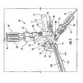
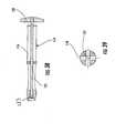
- a guide assembly 10 of one embodiment of the present inventionis shown coupled to a radius 11 of a patient in Figure 1 .
- the guide assembly 10is employed to install a fixation member 20 within the radius 11, as explained in further detail below.
- the fixation member 20is most suited for repairing fractures of the distal radius 11 wherein the fracture is at one end near an articular cartilage surface 12 and wherein it is desired to leave the articular surface undisrupted during the repair.
- reference is made herein to a guide assembly 10 and fixation member 20 suitable for the radiusit is understood that the guide assembly may be configured to install a fixation member within a variety of long bones, such as a femur, tibia, radius or humerus.
- the radius 11generally includes a widened end 13 that supports the articular cartilage surface which tapers to a more narrow shaft 14. Extending within the shaft 14 and a portion of the widened end 13 is a medullary canal 15.
- the guide assembly 10 and fixation member 20could be used to repair a variety of fractures of the long bones, but is shown being used to repair a first bone fragment 16 separated from a second bone fragment 17 by a single fracture line 18.
- a side aperture 19is defined in a lateral surface of the widened end 13, subjacent the articular cartilage surface 12, to allow insertion of the fixation member 20.
- the fixation member 20is configured to receive a plurality of fasteners 21 therethrough and attach to the radius I 1 above and below the fracture line 18 and thereby reduce the fracture, for example, as shown in Figure 2 .
- the curved body 24extends to a second end 23 which is positioned within the medullary canal 15 of the second bone fragment 17.
- a radius of curvature of the curved body 24is selected to promote smooth insertion of the curved body through the side aperture 19 and into the medullary canal 15.
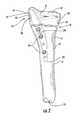
- fixation member 20 of the present inventionis shown in Figures 3-6 .
- the first end 22 of the fixation member 20has two intersecting flat surfaces, including an exposed first end surface 27 that is accessible through the side aperture 19 and an adjacent first end surface 28 that is at a right angle to the exposed surface, as shown in Figure 4 .
- the second end 23 of the fixation member 20may have a rounded profile.
- the curved body 24 of the fixation member 20includes a convex side 29 and a concave side 30 that are on opposite sides of the curved body.
- the sideshave radii of curvature with a similar center, but the center of the convex side changes so that the sides converge in a slight taper as they extend to the second end 23, as shown in Figure 4 .
- the radius of curvature of the concave side 30is about 3.12 inches and the radius of curvature of the convex side 29 is about 3.40 inches near the first end 22 when measured from a first center 31 positioned about 2.31 inches from the plane of the adjacent first end surface 28 and about 2.35 inches from the plane of the exposed first end surface 27.
- this shiftproduces the taper near the second end 23 of the fixation member 20.
- a second pair of opposite, side surfaces 33extend between the convex side 29 and concave side 30, as shown in Figures 3 , 5, and 6 . Similar to the convex side 29 and concave side 30, the side surfaces 33 taper slightly toward each other as they extend from the first end 22 to the second end 23 of the curved body 24. However, the side surfaces 33 in the illustrated embodiment are relatively planar, as opposed to the curved shape of the sides 29, 30. Advantageously, the taper of the sides 29, 30, 33, the continuous curve of the curved body 24 between the ends 22, 23 and the rounded profile of the second end 23 help to facilitate insertion through the side aperture 19 and into the medullary canal 15.
- a plurality of fastener openingsare defined in the fixation member. These fastener openings include a side aperture accessible fastener opening 34, a pair of fastener openings 35 extending between the curved convex side 29 and concave side 30, and fastener openings 36 extending between the side surfaces 33.
- the fastener opening 34extends from the exposed first end surface 27 (which is accessible through the side aperture 19 when the fixation member 20 is installed) through a portion of the curved body 24 and to the convex side 29, as shown in Figure 4 .
- the fastener opening 34includes a guide portion 38 and a fastener portion 39 that is generally narrower than the guide portion.
- Both of the portionsmay be threaded to facilitate a secure fit by the fasteners 21 and various installation devices, as will be described in more detail below.
- the pair of fastener openings 35which extend between the sides 29, 30 extend through the curved body 24 nearer the first end 22 so as to be within the first bone fragment 16, as shown in Figure 2 , 5, and 6 .
- Each of the fastener openings 35may have a threaded fastener portion similar to the fastener opening 34, but a non-threaded fastener head portion which may define a counterbore.
- These fastener openings 35extend at different, divergent angles than each other and the orientation of the fastener opening 34 which is relatively orthogonal with respect to the exposed first end surface 27 and the convex side 29, as shown in Figures 3 , 5, and 6 .
- the fastener openings(such as the fastener openings 35) need not all be aligned with the axis of the fixation member.
- angles of the fastener openings 34, 35may be configured so that the fasteners extend subjacent to the articular cartilage for improved fixation. Generally, this will require the fastener openings 34, 35 to extend at some acute angle, such as an angle between about 50° and 85° (depending on the origin of the fastener opening), and preferably about 60° to 70°, with respect to the fixation member 20. Basically, these angles are to match the inclination angle of the articular surface so as to provide a buttress effect for the articular cartilage.
- the ulnar inclination angle of the articular cartilage on the radiusis about 23° (resulting in a 67° fastener opening angle).
- the buttress effectis also improved by the sub-chondral placement of the first end surface 28 that is adjacent and at a right angle with respect to the exposed first end surface 27 so as to underlie the articular cartilage.
- fastener openings 36are defined in the curved body 24 at a position nearer the second end 23 of the fixation member 20.
- the fastener openings 36 having the larger diameterare configured to receive threaded fasteners 21 therethrough, similar to the fastener openings 34, 35, while the fastener openings having a smaller diameter are configured to receive a relatively smaller diameter Kirschner wire/k-wire 41.
- the larger of the fastener openings 36may not be threaded to allow a slip fit of the threaded fasteners 21 through the fixation member 20 without damaging the threads.
- Figure 2demonstrates that the fixation member 20 may be positioned within the radius 11 such that each of the larger fastener openings 36 may guide respective fasteners 21 in the second bone fragment 17.
- fixation member 20may include any number of desired fastener openings.
- the fixation member 20may be configured to be a size 1 or 2 implant such that increasing to a size 3 or 4 implant may include additional fastener openings 35 and/or 36.
- the fixation member 20could be a variety of configurations depending on the type of long bone, the patient, and/or other factors.
- U.S. Patent Appl. Publ. No. 2006/0015101filed July 15, 2004 .
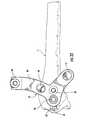
- FIG. 1illustrates a guide assembly 10 according to one embodiment of the present invention.
- the guide assemblygenerally includes a guide member 51, a distal guide member 52, and a proximal guide member 53.
- the guide member 51 and distal 52 and proximal 53 guide membersare capable of being engaged to and disengaged from each other so as to provide an interchangeable guide assembly 10 that may provide for easier installation of the fixation member 20 within the radius 11.
- FIGS 7-9illustrate a guide member 51 according to one embodiment of the present invention.
- the guide member 51is configured to be coupled to the distal end of the fixation member 20 via a guide fastener 54.
- the guide member 51includes a longitudinal opening 56 that is configured to receive the guide fastener 54 therethrough.
- the guide fastener 54includes a threaded end 58 that is configured to mate with threads defined in the fastener opening 34 of the fixation member 20.
- the guide member 51includes a plurality of prongs 60 that are configured to fit into similarly shaped, but somewhat smaller, concave indentations 40 in a positive, or interference, type fit, as shown, for example, in Figure 33 .
- the guide member 51 and its prongs 60which are also spaced in a cruciform or cross pattern similar to the indentations 40, are advanced into the indentations.
- the cruciform patterncombined with the positive fit, firmly locks the guide member 51 to the fixation member 20 before attaching the distal 52 and proximal 53 guide members, as well as during guidance of insertion of the various fasteners 21.
- the cruciform shape and positive fitmay be effective at restricting rotation between the guide assembly 10 and fixation member 20, which can be a problem due to the relative length and cantilevered configuration of the guide assembly and fixation member. It should be noted, however, that the positive fit of the prongs 60 in the concave indentations 40 could be accomplished in other ways, such as by having the indentations on the guide member 51 instead of the exposed first end surface 27 of the fixation member 20.
- the guide member 51also includes a handle mount 62 and a threaded opening 64 extending therethrough that is configured to mate with a handle 114, as shown in Figures 32-34 , 36 , and 37 .
- the handle 114is typically used to manipulate the fixation member 20 within the medullary canal 15, as explained in additional detail below.
- the guide member 51includes a protrusion 66 that also includes a threaded opening 68.
- the protrusionis configured to mate with a slot 76 defined in the distal guide member 52.
- the protrusion 66is shown as being generally rectangular, but could be various sizes and configurations to mate with the slot 76 of the distal guide member 52, such as tapered to engage a tapered slot in an interference type of fit.
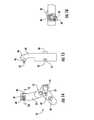
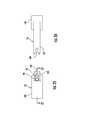
- Figures 10-13illustrate distal guide members 52 according to particular embodiments of the present invention.
- the distal guide member 52 shown in Figures 10-13may be used for guiding fasteners 21 within the first end 22 of the fixation member 20 and the first bone fragment 16.
- the distal guide member 52 shown in Figures 10 and 13may be configured to guide fasteners 21 within the patient's left radius 11, while the distal guide member 52 shown in Figures 11 and 12 may be used to guide fasteners in the right radius.
- Each of the distal guide members 52 shown in Figures 10-13includes a plurality of openings 70.
- the openings 70are oriented so as to have an axis collinear and aligned with the axes of the pair of openings 35 defined in the curved body 24 of the fixation member 20.
- the openings 70are defined so that the fasteners 21 extend at an angle into the first bone fragment 16 below the articular cartilage surface 12, as shown in Figure 2 .
- each tissue protector 72includes a head 75 and a longitudinal shaft 77, wherein the shaft is configured to extend through the openings 70 and adjacent to the radius.
- the distal end of the tissue protectoris capable of being inserted through the skin and abutting the radius.
- the offset distance between the distal guide member 52 and the patient's skinmay allow the distal guide member 52 to accommodate patients of a variety of sizes, while the tissue protectors 72 may protect the patient's skin from injury resulting from implanting the fixation member 20, such as from drilling into the tissue.
- the distal guide members 52include an opening 74 configured to receive the guide fastener 54 therethrough, as shown in Figures 20 and 21 .
- Figures 1 and 34show that the tissue protectors 72 and guide fastener 54 include respective longitudinal openings 73 that are configured to receive drill bits, k-wires, drill guides, fasteners, and the like in order to facilitate placement of the fixation member 20 within the radius 11.
- Figure 1shows each of the tissue protectors 72 and guide fastener 54 may have a drill guide 78 positioned therein.
- Each distal guide member 52also includes a slot 76 that is configured to mate with the protrusion 66 of the guide member 51. Extending within the slot 76 is a fastener 80 having a threaded end 82 that is configured to engage with the threads 68 of the protrusion 66. The engagement of the protrusion 66 and fastener 80 within the slot 76 provides resistance to rotational movement between the guide member 51 and the distal guide member 52, which may ensure more accurate placement of fasteners 21 within the radius 11.
- the slot 76is generally rectangular in configuration but could be modified to a variety of sizes and configurations to mate with the protrusion 66 and resist rotational movement therebetween.
- Each distal guide member 52 shown in Figures 10-13includes a hook-shaped portion 84 that includes a curvature that is configured to extend partially about the circumference of the patient's wrist and engage a proximal guide member 53.
- the distal guide members 52 of Figures 10-13include a fastener 86 and an associated threaded end 87 that is configured to thread an opening 92 defined in the proximal guide member 53, as shown in Figure 23 .
- the proximal guide member 53may include a fastener that is configured to engage threads defined in the distal guide member 52 such that the proximal and distal guide members are threadably engageable with one another.
- distal guide members 52 of Figures 10-13include an alignment pin 88 configured to engage an opening 94 defined in the proximal guide member 53, while the proximal guide member 53 may also include an alignment pin 96 that is configured to engage an opening 90 defined in the distal guide member 52.
- alignment pins and threaded engagement between the distal 52 and proximal 53 guide membersprovides a secure attachment, while also providing the surgeon with the option of removing the distal guide member, such as to replace the distal guide member with a different size.
- Figures 14-19illustrate additional embodiments of a distal guide member 52, where the distal guide member 52 of Figures 14-16 may be employed for the right radius, while the distal guide member 52 of Figures 17-19 may be used for the left radius.
- the distal guide members 52 of Figures 14-19are similar to the proximal guide members of Figures 10-13 , but provide a different technique for coupling the distal guide member 52 to the proximal guide member 53. More specifically, the hook-shaped portion 84 includes a protrusion 98 that extends across its width, as shown in Figures 14 and 17 .
- the protrusion 98is configured to engage a channel 100 defined in the proximal guide member 53 shown in Figures 25-27 .
- the engagement of the protrusion 98 within the channel 100may provide additional resistance to rotational movement between the distal 52 and proximal 53 guide members.
- the distal guide members 52 of Figures 14-19include a fastener 86 that is configured to engage a threaded opening 92 defined in the proximal guide member 53, as well as an alignment pin 88 that is configured to engage an opening 94 defined in the proximal guide member 53.
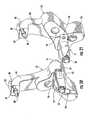
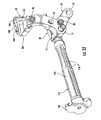
- the guide assembly 10further includes a proximal guide member 53 for guiding fasteners 21 within the second end 23 of the fixation member 20 and the second bone fragment 17, as shown in Figures 24-28 according to additional embodiments of the present invention.
- the proximal guide member 53is configured to engage a respective distal guide member 52, as shown in Figure 29 .
- the proximal guide member 53 of Figure 24is generally configured to be coupled to the distal guide members 52 shown in Figures 10-13 .
- the proximal guide member 53is generally L-shaped in configuration and includes a first portion 102 for engaging with the distal guide member 52 and a second portion 104 for guiding respective fasteners 21 into respective openings 36 defined in the fixation member 20.
- the second portion 104includes a plurality of openings 106 that are configured to receive various devices for implanting the fixation member 20, such as a tube protector 72, as shown in Figure 34 .
- the second portion 104includes a smaller opening 108 that could be configured to receive a k-wire 41 or similar device therein.
- Figures 25-27illustrate a proximal guide member 53 according to an additional embodiment of the present invention, which is configured to be coupled to the distal guide members 52 illustrated in Figures 14-19 .
- the proximal guide member 53includes a channel 100 that is configured to receive the protrusion 98, as shown in Figures 32 and 33 .
- Different proximal guides 53can also be used for different sized fixation members 20.
- Figure 28shows a proximal guide member 53 having additional openings 106 for accommodating a longer fixation member 20.
- the proximal guide member 53can be employed in right and left handed configurations depending on the type of long bone being treated and the orientation of the side aperture 19.
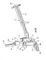
- Figure 29illustrates a wrench 110 that is configured to engage various fasteners of the guide assembly 10.
- the wrench 110is configured to mate with the head of fastener 86 so as to tighten the threaded end 87 within the threaded opening 92 of the proximal guide member 53.
- the wrench 110is also compatible with the head of the guide fastener 54 and fastener 80.
- the wrench 110provides a universal tool that may be used with different fasteners used in assembling the guide assembly 10, as well as securing the guide assembly to the fixation member 20.
- the wrench 110may include a plurality of longitudinal slots 112 in order to reduce weight.
- the guide member 51includes a threaded opening 64 that is configured to receive a handle 114.
- the handle 114is typically attached to the guide member 51 in order to facilitate installation of the fixation member 20 through the side aperture 19 and into the medullary canal 15.
- the handle 114generally includes a body portion 116 and a plurality of slots 118 defined therein.
- the handle 114may include a strike plate 120 that includes a shaft 121 that extends the length of the body portion 116 and a threaded end 123 that is configured to mate with the threaded opening 64 of the guide member 51, as shown in Figure 38 .
- the strike plate 120may cause loosening or tightening of the shaft 121 to the guide member 51.
- the surgeonmay contact the strike plate 120 with a hammer in order to aid in implanting the fixation member 20 within the radius 11.
- the slots 118provide a technique for removing bone fragments or otherwise cleaning any bone fragments removed from the radius while installing the fixation member.
- Figure 39shows that the slots 118 may extend radially within the body portion 116 to the shaft 121. There may be any number of slots 118 defined in the body portion 114, and the slots may extend the entire length of the body portion or include a plurality of axially aligned slots, as shown in Figure 33 .
- the guide assembly 10also includes a plurality of drill guides 78 as shown in Figure 1 .
- the drill guides 78are employed to receive a drill bit, as well as facilitate measurement of the depth of holes drilled within the radius 11.
- the drill guides 78may include a plurality of measurement indicators 122 that are used by the surgeon to determine a fastener 21 and/or k-wire 41 of the appropriate length based on the depth of the hole within the radius 11.
- the drill guides 78include a shaft 124 that is configured to slide within the opening 73 of the tissue protectors 72, through the holes 34, 35, and/or 36, and into the radius 11.
- the drill guides 78include a longitudinal slot 126 that extends the length of the drill guide, which is configured to slidably receive a drill bit or k-wire 41 therein.
- a guide shaft openingdefined within the elongate shaft 124 of the drill guide 78 is a guide shaft opening that tapers from a wider to narrower diameter near its distal end.
- a dual diameter drill bitcould be used to drill a hole within radius 11, wherein the larger diameter of the drill bit prevents travel of the drill bit beyond the shoulder defined near the distal end of the drill guide 78 so as to prevent drilling past a selected depth.
- the depth of the hole drilled in the radius 11may be determined based on the alignment of a predetermined marking on the k-wire 41 with one of the measurement indicators 122.
- the k-wire 41 and/or measurement indictors 122could also employ fluorescent paint or grooved notches to facilitate reading of the measurements.
- the drill guides 78are capable of being removed from respective tissue protectors 72 while k-wires 41 are inserted therein, which may aid the surgeon in viewing the k-wire within the radius 11.
- the tissue protectors 72could also be removed from the distal 52 and proximal 53 guide members while the k-wires 41 are inserted within the radius 11 in order to visualize the radius 11 if desired.
- the distal 52 and proximal 53 membersmay be a radiolucent material.
- the distal 52 and proximal 53 guide membersdo not obstruct images taken of the radius during implantation of the fixation member 20, such as images taken using radiographic techniques.
- the radiolucent materialcould be a carbon reinforced PEEK material, which is lighter than conventional stainless steel guide assemblies.
- a guide assembly 10 comprising a lighter materialmay be easier to handle by a surgeon and apply less torque on the bone fragments.
- other components of the guide assemblycould be a radiolucent material, such as the tissue protectors 72, k-wires 41, and/or handle body 116, in order to reduce weight of the guide assembly 10, as well as provide better visualization of the fixation member 20 within the radius during surgery.
- a side aperture 19is cleared in a lateral side of the radius 11, and a conventional bone awl (not shown) may be used to open the medullary canal 15 of cancellous bone.
- a trialing broachmay be urged through the side aperture 19 and into the medullary canal 15 to approximate the size of the fixation member 20.
- Other conventional toolscould also be employed to clear bone, such as reamers and awls.
- an appropriately sized fixation member 20may be selected.
- the handle 114is attached to the threaded opening 64 defined in the guide member 51, as shown in Figures 32-34 .
- the guide member 51may then be attached to the fixation member 20 via the guide fastener 54.
- the threaded tip 58 of the guide fastener 54may be advanced into the threaded opening 34 of the fixation member 20, which mates the prongs 60 with the indentations 40, thereby locking out micro-motion and rotation between the guide member 51 and the fixation member 20.
- the handle 114may then be used to orient the fixation member 20 through the side aperture 19 and into the medullary canal 15.
- the handle 114may then be then unscrewed from the guide member 51.
- the distal guide member 52may then be attached to the guide member 51 by inserting the protrusion 66 within the slot 76 and tightening the fastener 80 to the threaded opening 68, as shown in Figures 20 and 21 .
- the proximal guide member 53may then be attached to the distal guide member 52 by sliding the protrusion 98 within the channel 100 such that the alignment pin 88 aligns with the opening 94.
- the fastener 86may then be tightened to secure the threaded end 87 within the threaded opening 92.
- tissue protectors 72within each of the openings 70 of the distal guide member 52 and the openings 106 of the proximal guide member 53.
- a k-wire 41may be inserted within the smaller guide openings 36, 108 of the distal 52 and proximal 53 guide members, respectively.
- the drill guides 78may then be placed into respective tissue protectors 72, as well as within the guide fastener 54.
- a drill bit(not shown) may be advanced into the drill guides 78 to form pilot holes in the radius 11.
- the depth of these holesmay then be tested using measurement indicators 122 by inserting a k-wire within the longitudinal slot 126 of the drill guides 78, as shown in Figure 1 .
- the depth measurementsfacilitate selection of fasteners 21 of the appropriate length.
- the drilled holesare then tapped to prepare them for insertion of threaded fasteners 21.
- the threaded fasteners 21may be advanced through the aligned openings 34, 35, 36, 106 in the fixation member 20 and the radius I 1 so as to connect the bone fragments 16, 17, as shown in Figure 2 .
- the guide assembly 10can then be removed by unscrewing the guide fastener 54.
- the guide member 51may be coupled to the fixation member 20 without first having to attach the distal guide member 52 and/or proximal guide member 53.
- the surgeonmay be able to more easily position the fixation member 20 within the radius 11 since the surgeon will have a better view of the radius and will have a lighter device to manipulate.
- the distal guide member 52is interchangeable with the guide member 51 such that the surgeon could remove the distal guide member 52 during surgery, such as for better visualization or to change to a different size.
- attachment of the guide member 51 to the fixation member 20 with the guide fastener 54provides a secure engagement that allows the distal guide member 52 to be attached and removed when desired.
- proximal guide member 53is interchangeable with the distal guide member 52 such that the proximal guide member may be selectively engaged to and disengaged from the distal guide member. Therefore, the combination of the guide member 51, distal guide member 52, and proximal guide member 53 provides interchangeable components for a more universal guide assembly 10.
- distal 52 and proximal 53 membersmay be a radiolucent material, which also enhances visualization during surgery, as well as reduces the weight of the guide assembly, thereby resulting in easier manipulation of the assembly and less torque on the bone fragments.
- the distal 52 and proximal 53 guide membersare also configured to be spaced away from the patient's radius 11 such that the guide assembly 10 is adaptable to various sized patients.
- the offset distance between the distal 52 and proximal 53 guide members from the patient's skinallows tissue protectors 72 to be placed within each of the holes 70, 106 in order to provide additional protection from injuring the patient's skin during installation of the fixation member 20.
Landscapes
- Health & Medical Sciences (AREA)
- Surgery (AREA)
- Life Sciences & Earth Sciences (AREA)
- Orthopedic Medicine & Surgery (AREA)
- Biomedical Technology (AREA)
- Public Health (AREA)
- Veterinary Medicine (AREA)
- Engineering & Computer Science (AREA)
- Nuclear Medicine, Radiotherapy & Molecular Imaging (AREA)
- Heart & Thoracic Surgery (AREA)
- Medical Informatics (AREA)
- Molecular Biology (AREA)
- Animal Behavior & Ethology (AREA)
- General Health & Medical Sciences (AREA)
- Dentistry (AREA)
- Oral & Maxillofacial Surgery (AREA)
- Neurology (AREA)
- Surgical Instruments (AREA)
Description
- The present invention is related to the use of orthopedic fixation devices and devices for installing the same, and in particular, to intramedullary fixation devices and guides for facilitating installation and fixation of the same within the distal radius.
- Long bone fractures are fairly common in the elderly population, often due to the onset of osteoporosis. Long bone fractures may be reduced by the use of assorted conventional bone plates. For example, a bone plate may be attached to the outside surface of two adjacent fragments of a long bone and then secured by inserting bone screws through openings in the bone plate. Problems may arise with such bone plates, however, in that the soft tissues covering the bone plates may become irritated by passage or movement over the bone plates.
- An alternative to bone plates are intramedullary nails or rods that extend through a medullary canal defined within the fractured long bone. The nails or rods are typically fastened to the fractured portions of the long bones with bone screws. The nails or rods are placed into the medullary canal by insertion through a hole which is drilled into one end of the long bone. For instance, to reduce a fractured femur with an intramedullary rod or nail, a hole is drilled through the articular cartilage between the condyles to provide access for the rod. Because the intramedullary nails or rods are contained within the medullary canal, they avoid the problems with soft tissue associated with plates. However, insertion of these rods through holes in the ends of the longs bones requires damaging the articular cartilage on the ends of the long bones.
U.S. Patent No. 6,527,775 to Warburton ("the '775 patent"), describes an intramedullary fixation device used to reduce a distal fracture of the radius. As shown in Figure 3A of the '775 patent, the intramedullary fixation device 25 includes an elongated axially extending rod 26 with adistal portion 27 and aproximal portion 28. The fixation device also includes adistal fixation member 30 andproximal fixation members 35. The distal fixation member extends through the distal portion of the rod and into adistal fracture fragment 18. The proximal fixation members extend through the proximal portion of the rod and the portion of the radius proximal the fracture line.- Furthermore, the '775 patent discloses an insertion guide device 150 for guiding fixation members 35a, 35b into proximal fixation apertures 25a1, 25a2. The insertion guide device includes visual indicia 153, 155 that function as drill guides that align with the fixation apertures 25a1, 25a2. The insertion guide 150 attaches to a
distal end portion 27 of the rod 26 and includes an axially extending arm residing external of the body. In addition, the insertion guide 150 is attached to the rod 26 prior to inserting the rod within the medullary canal. - Although the '775 patent discloses an insertion guide device for facilitating placement of the rod within the medullary canal, it would be advantageous to provide a guide assembly that facilitates easier placement of a fixation member within a radius. It would also be advantageous to provide a guide assembly that is capable of being easily assembled and disassembled and that provides a surgeon with more effective techniques for implanting a fixation member within a radius of a variety of patients.
- Moreover
GB-A-2 290 478 GB-A-2 290 478 - Embodiments of the present invention may address the above needs and achieve other advantages by providing a guide assembly for installing a fixation member within the medullary canal of the radius. The guide assembly generally provides an interchangeable guide assembly that allows the physician to more easily manipulate the fixation member, as well as adapt to patients of various sizes. The guide assembly may also comprise lighter and radiolucent material, which may also improve the installation process.
- More specifically the invention refers to a guide assembly according to claim 1.
- The guide fastener may also include an opening configured to receive a drill guide therethrough. The guide member may include a threaded opening for receiving a fastener to secure the proximal guide member to the guide member.
- Additional aspects of the guide assembly include providing a handle that may attach to the guide member. The distal guide member may include a protrusion, and the proximal guide member may include a channel for receiving the protrusion therein. The proximal guide member and distal guide member may be configured for threaded engagement. In addition, the distal guide member may include an alignment pin configured to engage an opening defined in the proximal guide member. The guide assembly may further include a plurality of tissue protectors, wherein each of the plurality of fastener guide openings of the proximal guide member and distal guide member may be configured to receive a respective tissue protector therethrough. The proximal and distal guide members are spaced outwardly from the radius such that the tissue protectors are configured to extend through the proximal guide member and distal guide member and adjacent to the radius. Moreover, the guide assembly may include a plurality of drill guides, wherein each of the plurality of tissue protectors is configured to receive a respective one of the drill guides therein.
- An additional embodiment of the present invention provides an intramedullary fixation member kit for repairing a radius fracture. The kit includes an intramedullary fixation device configured to be positioned within an intramedullary canal of a radius and defining a plurality of fastener openings for receiving respective fasteners therethrough. The kit also includes a guide member configured to be coupled to the intramedullary fixation device and an interchangeable distal guide member configured to engage and be disengaged from the guide member. The distal guide member defines a plurality of fastener guide openings for guiding respective fasteners through a plurality of fastener openings defined in the intramedullary fixation member. The kit may also include an interchangeable proximal guide member and/or a guide fastener, as described above.
- A method for placing a fixation member within a medullary canal of a radius is also described. The method includes defining a side aperture in the radius that extends into a medullary canal thereof and attaching a guide member to the fixation member with a guide fastener. The method further includes inserting the fixation member through the side aperture until the fixation member is positioned in the medullary canal and side aperture and attaching an interchangeable distal guide member to the guide member, wherein the distal guide member defines a plurality of fastener guide openings. Moreover, the method includes defining a plurality of fastener openings within the radius via the plurality of fastener guide openings defined in the distal guide member that align with a plurality of fastener openings defined in the fixation member. The method also includes advancing a plurality of bone fasteners through the plurality of fastener guide openings defined in the distal guide member and the plurality of fastener openings defined in the fixation member and the radius.
- Variations of the method include attaching an interchangeable proximal guide member to the distal guide member, wherein the proximal guide member defines a plurality of fastener guide openings. The method may further include defining a plurality of fastener openings within the radius via the plurality of fastener guide openings defined in the proximal guide member that align with a plurality of fastener openings defined in the fixation member that are located proximally of the plurality of fastener openings defined via the distal guide member. Furthermore, the method may include detaching the distal guide member from the guide member while the guide member is attached to the fixation member.
- Having thus described the invention in general terms, reference will now be made to the accompanying drawings, which are not necessarily drawn to scale, and wherein:
Figure 1 is a perspective view of a guide assembly coupled to a fixation member according to one embodiment of the present invention;Figure 2 is a side elevation view of a fixation member positioned within the medullary canal of a radius according to one embodiment of the present invention;Figure 3 is a perspective view of the fixation member ofFigure 1 ;Figures 4-6 are side elevation views of the fixation member ofFigure 3 ;Figure 7 is a perspective view of a guide member according to one embodiment of the present invention;Figure 8 is an end view of the guide member ofFigure 6 ;Figure 9 is a cross-sectional view of the guide member ofFigure 6 ;Figure 10 is an elevation view of a distal guide member according to one embodiment of the present invention;Figure 11 is an elevation view of a distal guide member according to an embodiment of the present invention;Figure 12 is a perspective view of distal guide member ofFigure 11 ;Figure 13 is a perspective view of distal guide member ofFigure 10 ;Figures 14 and 15 are side elevation views of a distal guide member of another embodiment of the present invention;Figure 16 is a cross-sectional view of the distal guide member ofFigure 14 ;Figures 17 and 18 are side elevation views of a distal guide member of one embodiment of the present invention;Figure 19 is a cross-sectional view of the distal guide member ofFigure 17 ;Figure 20 is perspective view of a guide member coupled to a distal guide member according to one embodiment of the present invention;Figure 21 is perspective view of a guide member coupled to a distal guide member according to an embodiment of the present invention;Figure 22 is a side elevation view of a distal guide member coupled to a radius according to one embodiment of the present invention;Figure 23 is a side elevation view of a guide member coupled to radius, a distal guide member coupled to the guide member, and a proximal guide member prior to engaging the distal guide member, according to one embodiment of the present invention;Figure 24 is a perspective view of the proximal guide member shown inFigure 23 ;Figures 25 and 26 are side elevation views of a proximal guide member according to one embodiment of the present invention;Figure 27 is a cross-sectional view of the proximal guide member ofFigure 25 ;Figure 28 is a side elevation view of a proximal guide member according to another embodiment of the present invention;Figure 29 is a perspective view of a guide member coupled to a distal radius, a distal guide member coupled to the guide member, and the distal guide member coupled to a proximal guide member, according to one embodiment of the present invention;Figures 30 and 31 are side elevation views of a guide member coupled to a distal radius, a distal guide member coupled to the guide member, and the distal guide member coupled to a proximal guide member, according to one embodiment of the present invention;Figures 32 and33 are perspective views of a guide assembly and a handle coupled thereto according to one embodiment of the present invention;Figure 34 is a perspective view of a guide assembly ofFigures 32 and33 coupled to the radius and tissue protectors positioned within the proximal and distal guide members according to one embodiment of the present invention;Figure 35 is a perspective view of a drill guide according to one embodiment of the present invention;Figure 36 is a perspective view of a guide assembly including drill guides and respective drill guides positioned therein, according to one embodiment of the present invention;Figure 37 is a side elevation view of a guide assembly including drill guides and respective drill guides positioned therein, according to one embodiment of the present invention; andFigures 38 and 39 are cross-sectional views of a handle according to one embodiment of the present invention.- The present invention now will be described more fully hereinafter with reference to the accompanying drawings, in which some, but not all embodiments of the invention are shown. Indeed, this invention may be embodied in many different forms and should not be construed as limited to the embodiments set forth herein; rather, these embodiments are provided so that this disclosure will satisfy applicable legal requirements. Like numbers refer to like elements throughout.
- A
guide assembly 10 of one embodiment of the present invention is shown coupled to aradius 11 of a patient inFigure 1 . Theguide assembly 10 is employed to install afixation member 20 within theradius 11, as explained in further detail below. Thefixation member 20 is most suited for repairing fractures of thedistal radius 11 wherein the fracture is at one end near anarticular cartilage surface 12 and wherein it is desired to leave the articular surface undisrupted during the repair. Although reference is made herein to aguide assembly 10 andfixation member 20 suitable for the radius, it is understood that the guide assembly may be configured to install a fixation member within a variety of long bones, such as a femur, tibia, radius or humerus. - As shown in
Figure 2 , theradius 11 generally includes awidened end 13 that supports the articular cartilage surface which tapers to a morenarrow shaft 14. Extending within theshaft 14 and a portion of thewidened end 13 is amedullary canal 15. In addition, theguide assembly 10 andfixation member 20 could be used to repair a variety of fractures of the long bones, but is shown being used to repair afirst bone fragment 16 separated from asecond bone fragment 17 by asingle fracture line 18. Aside aperture 19 is defined in a lateral surface of thewidened end 13, subjacent thearticular cartilage surface 12, to allow insertion of thefixation member 20. - Generally, the
fixation member 20 is configured to receive a plurality offasteners 21 therethrough and attach to the radius I 1 above and below thefracture line 18 and thereby reduce the fracture, for example, as shown inFigure 2 . Theelongate fixation member 20, when positioned within themedullary canal 15 of theradius 11, has afirst end 22 positioned adjacent theside aperture 19. Extending from the first end, through the rest of the aperture and into themedullary canal 15 of thefirst bone fragment 16, is a curved body 24 (shown in broken lines inFigure 2 ) of thefixation member 20. Thecurved body 24 extends to asecond end 23 which is positioned within themedullary canal 15 of thesecond bone fragment 17. Advantageously, a radius of curvature of thecurved body 24 is selected to promote smooth insertion of the curved body through theside aperture 19 and into themedullary canal 15. - For example, one embodiment of the
fixation member 20 of the present invention is shown inFigures 3-6 . Thefirst end 22 of thefixation member 20 has two intersecting flat surfaces, including an exposedfirst end surface 27 that is accessible through theside aperture 19 and an adjacentfirst end surface 28 that is at a right angle to the exposed surface, as shown inFigure 4 . Thesecond end 23 of thefixation member 20 may have a rounded profile. - The
curved body 24 of thefixation member 20 includes aconvex side 29 and aconcave side 30 that are on opposite sides of the curved body. The sides have radii of curvature with a similar center, but the center of the convex side changes so that the sides converge in a slight taper as they extend to thesecond end 23, as shown inFigure 4 . For instance, the radius of curvature of theconcave side 30 is about 3.12 inches and the radius of curvature of theconvex side 29 is about 3.40 inches near thefirst end 22 when measured from afirst center 31 positioned about 2.31 inches from the plane of the adjacentfirst end surface 28 and about 2.35 inches from the plane of the exposedfirst end surface 27. Notably, this shift produces the taper near thesecond end 23 of thefixation member 20. - A second pair of opposite, side surfaces 33 extend between the
convex side 29 andconcave side 30, as shown inFigures 3 ,5, and 6 . Similar to theconvex side 29 andconcave side 30, the side surfaces 33 taper slightly toward each other as they extend from thefirst end 22 to thesecond end 23 of thecurved body 24. However, the side surfaces 33 in the illustrated embodiment are relatively planar, as opposed to the curved shape of thesides sides curved body 24 between theends second end 23 help to facilitate insertion through theside aperture 19 and into themedullary canal 15. - To allow passage of the
fasteners 21 through the fixation member, a plurality of fastener openings are defined in the fixation member. These fastener openings include a side apertureaccessible fastener opening 34, a pair offastener openings 35 extending between the curvedconvex side 29 andconcave side 30, andfastener openings 36 extending between the side surfaces 33. Thefastener opening 34 extends from the exposed first end surface 27 (which is accessible through theside aperture 19 when thefixation member 20 is installed) through a portion of thecurved body 24 and to theconvex side 29, as shown inFigure 4 . Thefastener opening 34 includes aguide portion 38 and afastener portion 39 that is generally narrower than the guide portion. Both of the portions may be threaded to facilitate a secure fit by thefasteners 21 and various installation devices, as will be described in more detail below. Defined around the periphery of theguide portion 38 of thefastener opening 34 are fourindentations 40. Theseindentations 40 are arranged in a cross, or cruciform, shape each radiating out from thefastener opening 34 and spaced 90° from each other. As will be described in more detail below, theconcave indentations 40 serve to provide for a secure, properly oriented positive fit with aguide assembly 10. - The pair of
fastener openings 35 which extend between thesides curved body 24 nearer thefirst end 22 so as to be within thefirst bone fragment 16, as shown inFigure 2 ,5, and 6 . Each of thefastener openings 35 may have a threaded fastener portion similar to thefastener opening 34, but a non-threaded fastener head portion which may define a counterbore. Thesefastener openings 35 extend at different, divergent angles than each other and the orientation of thefastener opening 34 which is relatively orthogonal with respect to the exposedfirst end surface 27 and theconvex side 29, as shown inFigures 3 ,5, and 6 . As a result, the fastener openings (such as the fastener openings 35) need not all be aligned with the axis of the fixation member. - These different angles improve fixation by allowing angled insertion of the
fasteners 21 into different portions of thefirst bone fragment 16, as shown inFigure 2 . In addition, the angles of thefastener openings fastener openings fixation member 20. Basically, these angles are to match the inclination angle of the articular surface so as to provide a buttress effect for the articular cartilage. For instance, the ulnar inclination angle of the articular cartilage on the radius is about 23° (resulting in a 67° fastener opening angle). The buttress effect is also improved by the sub-chondral placement of thefirst end surface 28 that is adjacent and at a right angle with respect to the exposedfirst end surface 27 so as to underlie the articular cartilage. - In the illustrated embodiment shown in
Figures 3 and4 , sixfastener openings 36 are defined in thecurved body 24 at a position nearer thesecond end 23 of thefixation member 20. Thefastener openings 36 having the larger diameter are configured to receive threadedfasteners 21 therethrough, similar to thefastener openings wire 41. The larger of thefastener openings 36 may not be threaded to allow a slip fit of the threadedfasteners 21 through thefixation member 20 without damaging the threads. Furthermore,Figure 2 demonstrates that thefixation member 20 may be positioned within theradius 11 such that each of thelarger fastener openings 36 may guiderespective fasteners 21 in thesecond bone fragment 17. - Although six fastener openings are shown in the illustrated
fixation member 20, it is understood that the fixation member may include any number of desired fastener openings. For example, thefixation member 20 may be configured to be a size 1 or 2 implant such that increasing to a size 3 or 4 implant may includeadditional fastener openings 35 and/or 36. Moreover, it is understood that thefixation member 20 could be a variety of configurations depending on the type of long bone, the patient, and/or other factors. For additional details regarding a fixation member and bone fasteners according to additional embodiments of the present invention, see U.S. Patent Appl. Publ. No.2006/0015101, filed July 15, 2004 . Figure 1 illustrates aguide assembly 10 according to one embodiment of the present invention. The guide assembly generally includes aguide member 51, adistal guide member 52, and aproximal guide member 53. As discussed in detail below, theguide member 51 and distal 52 and proximal 53 guide members are capable of being engaged to and disengaged from each other so as to provide aninterchangeable guide assembly 10 that may provide for easier installation of thefixation member 20 within theradius 11.Figures 7-9 illustrate aguide member 51 according to one embodiment of the present invention. Theguide member 51 is configured to be coupled to the distal end of thefixation member 20 via aguide fastener 54. In particular, theguide member 51 includes alongitudinal opening 56 that is configured to receive theguide fastener 54 therethrough. Theguide fastener 54 includes a threadedend 58 that is configured to mate with threads defined in thefastener opening 34 of thefixation member 20. Moreover, theguide member 51 includes a plurality ofprongs 60 that are configured to fit into similarly shaped, but somewhat smaller,concave indentations 40 in a positive, or interference, type fit, as shown, for example, inFigure 33 .- When the threaded
end 58 is advanced into the threads of theguide portion 38, theguide member 51 and itsprongs 60, which are also spaced in a cruciform or cross pattern similar to theindentations 40, are advanced into the indentations. The cruciform pattern, combined with the positive fit, firmly locks theguide member 51 to thefixation member 20 before attaching the distal 52 and proximal 53 guide members, as well as during guidance of insertion of thevarious fasteners 21. The cruciform shape and positive fit may be effective at restricting rotation between theguide assembly 10 andfixation member 20, which can be a problem due to the relative length and cantilevered configuration of the guide assembly and fixation member. It should be noted, however, that the positive fit of theprongs 60 in theconcave indentations 40 could be accomplished in other ways, such as by having the indentations on theguide member 51 instead of the exposedfirst end surface 27 of thefixation member 20. - The
guide member 51 also includes ahandle mount 62 and a threadedopening 64 extending therethrough that is configured to mate with ahandle 114, as shown inFigures 32-34 ,36 , and37 . Thehandle 114 is typically used to manipulate thefixation member 20 within themedullary canal 15, as explained in additional detail below. Moreover, theguide member 51 includes aprotrusion 66 that also includes a threadedopening 68. As also explained in further detail below, the protrusion is configured to mate with aslot 76 defined in thedistal guide member 52. Theprotrusion 66 is shown as being generally rectangular, but could be various sizes and configurations to mate with theslot 76 of thedistal guide member 52, such as tapered to engage a tapered slot in an interference type of fit. Figures 10-13 illustratedistal guide members 52 according to particular embodiments of the present invention. Thedistal guide member 52 shown inFigures 10-13 may be used for guidingfasteners 21 within thefirst end 22 of thefixation member 20 and thefirst bone fragment 16. In particular, thedistal guide member 52 shown inFigures 10 and13 may be configured to guidefasteners 21 within the patient'sleft radius 11, while thedistal guide member 52 shown inFigures 11 and12 may be used to guide fasteners in the right radius.- Each of the
distal guide members 52 shown inFigures 10-13 includes a plurality ofopenings 70. Theopenings 70 are oriented so as to have an axis collinear and aligned with the axes of the pair ofopenings 35 defined in thecurved body 24 of thefixation member 20. According to one embodiment, theopenings 70 are defined so that thefasteners 21 extend at an angle into thefirst bone fragment 16 below thearticular cartilage surface 12, as shown inFigure 2 . - Furthermore, the
openings 70 are configured to slidably receiverespective tissue protectors 72 therethrough, as shown inFigure 34 . Eachtissue protector 72 includes ahead 75 and alongitudinal shaft 77, wherein the shaft is configured to extend through theopenings 70 and adjacent to the radius. Thus, the distal end of the tissue protector is capable of being inserted through the skin and abutting the radius. The offset distance between thedistal guide member 52 and the patient's skin may allow thedistal guide member 52 to accommodate patients of a variety of sizes, while thetissue protectors 72 may protect the patient's skin from injury resulting from implanting thefixation member 20, such as from drilling into the tissue. Furthermore, thedistal guide members 52 include anopening 74 configured to receive theguide fastener 54 therethrough, as shown inFigures 20 and 21 .Figures 1 and34 show that thetissue protectors 72 and guidefastener 54 include respectivelongitudinal openings 73 that are configured to receive drill bits, k-wires, drill guides, fasteners, and the like in order to facilitate placement of thefixation member 20 within theradius 11. For example,Figure 1 shows each of thetissue protectors 72 and guidefastener 54 may have adrill guide 78 positioned therein. - Each
distal guide member 52 also includes aslot 76 that is configured to mate with theprotrusion 66 of theguide member 51. Extending within theslot 76 is afastener 80 having a threadedend 82 that is configured to engage with thethreads 68 of theprotrusion 66. The engagement of theprotrusion 66 andfastener 80 within theslot 76 provides resistance to rotational movement between theguide member 51 and thedistal guide member 52, which may ensure more accurate placement offasteners 21 within theradius 11. Theslot 76 is generally rectangular in configuration but could be modified to a variety of sizes and configurations to mate with theprotrusion 66 and resist rotational movement therebetween. - Each
distal guide member 52 shown inFigures 10-13 includes a hook-shapedportion 84 that includes a curvature that is configured to extend partially about the circumference of the patient's wrist and engage aproximal guide member 53. Thedistal guide members 52 ofFigures 10-13 include afastener 86 and an associated threadedend 87 that is configured to thread anopening 92 defined in theproximal guide member 53, as shown inFigure 23 . However, it is understood that theproximal guide member 53 may include a fastener that is configured to engage threads defined in thedistal guide member 52 such that the proximal and distal guide members are threadably engageable with one another. In addition, thedistal guide members 52 ofFigures 10-13 include analignment pin 88 configured to engage anopening 94 defined in theproximal guide member 53, while theproximal guide member 53 may also include analignment pin 96 that is configured to engage anopening 90 defined in thedistal guide member 52. Thus, the combination of alignment pins and threaded engagement between the distal 52 and proximal 53 guide members provides a secure attachment, while also providing the surgeon with the option of removing the distal guide member, such as to replace the distal guide member with a different size. Figures 14-19 illustrate additional embodiments of adistal guide member 52, where thedistal guide member 52 ofFigures 14-16 may be employed for the right radius, while thedistal guide member 52 ofFigures 17-19 may be used for the left radius. Thedistal guide members 52 ofFigures 14-19 are similar to the proximal guide members ofFigures 10-13 , but provide a different technique for coupling thedistal guide member 52 to theproximal guide member 53. More specifically, the hook-shapedportion 84 includes aprotrusion 98 that extends across its width, as shown inFigures 14 and17 . Theprotrusion 98 is configured to engage achannel 100 defined in theproximal guide member 53 shown inFigures 25-27 . Thus, the engagement of theprotrusion 98 within thechannel 100 may provide additional resistance to rotational movement between the distal 52 and proximal 53 guide members. As before, thedistal guide members 52 ofFigures 14-19 include afastener 86 that is configured to engage a threadedopening 92 defined in theproximal guide member 53, as well as analignment pin 88 that is configured to engage anopening 94 defined in theproximal guide member 53.- The
guide assembly 10 further includes aproximal guide member 53 for guidingfasteners 21 within thesecond end 23 of thefixation member 20 and thesecond bone fragment 17, as shown inFigures 24-28 according to additional embodiments of the present invention. Theproximal guide member 53 is configured to engage a respectivedistal guide member 52, as shown inFigure 29 . In particular, theproximal guide member 53 ofFigure 24 is generally configured to be coupled to thedistal guide members 52 shown inFigures 10-13 . - The
proximal guide member 53 is generally L-shaped in configuration and includes afirst portion 102 for engaging with thedistal guide member 52 and asecond portion 104 for guidingrespective fasteners 21 intorespective openings 36 defined in thefixation member 20. In particular, thesecond portion 104 includes a plurality ofopenings 106 that are configured to receive various devices for implanting thefixation member 20, such as atube protector 72, as shown inFigure 34 . In addition, thesecond portion 104 includes asmaller opening 108 that could be configured to receive a k-wire 41 or similar device therein. Figures 25-27 illustrate aproximal guide member 53 according to an additional embodiment of the present invention, which is configured to be coupled to thedistal guide members 52 illustrated inFigures 14-19 . As described above, theproximal guide member 53 includes achannel 100 that is configured to receive theprotrusion 98, as shown inFigures 32 and33 . Different proximal guides 53 can also be used for differentsized fixation members 20. For example,Figure 28 shows aproximal guide member 53 havingadditional openings 106 for accommodating alonger fixation member 20. In addition, theproximal guide member 53 can be employed in right and left handed configurations depending on the type of long bone being treated and the orientation of theside aperture 19.Figure 29 illustrates awrench 110 that is configured to engage various fasteners of theguide assembly 10. For example,Figure 29 illustrates that thewrench 110 is configured to mate with the head offastener 86 so as to tighten the threadedend 87 within the threadedopening 92 of theproximal guide member 53. Thewrench 110 is also compatible with the head of theguide fastener 54 andfastener 80. Thus, thewrench 110 provides a universal tool that may be used with different fasteners used in assembling theguide assembly 10, as well as securing the guide assembly to thefixation member 20. Thewrench 110 may include a plurality oflongitudinal slots 112 in order to reduce weight.- As briefly mentioned above, the
guide member 51 includes a threadedopening 64 that is configured to receive ahandle 114. Thehandle 114 is typically attached to theguide member 51 in order to facilitate installation of thefixation member 20 through theside aperture 19 and into themedullary canal 15. Thehandle 114 generally includes abody portion 116 and a plurality ofslots 118 defined therein. In addition, thehandle 114 may include astrike plate 120 that includes ashaft 121 that extends the length of thebody portion 116 and a threadedend 123 that is configured to mate with the threadedopening 64 of theguide member 51, as shown inFigure 38 . Thus, rotation of thestrike plate 120 in a counterclockwise or clockwise direction may cause loosening or tightening of theshaft 121 to theguide member 51. Moreover, the surgeon may contact thestrike plate 120 with a hammer in order to aid in implanting thefixation member 20 within theradius 11. Because thebody portion 116 may receive bone fragments therein as thefixation member 20 is positioned within theradius 11, theslots 118 provide a technique for removing bone fragments or otherwise cleaning any bone fragments removed from the radius while installing the fixation member.Figure 39 shows that theslots 118 may extend radially within thebody portion 116 to theshaft 121. There may be any number ofslots 118 defined in thebody portion 114, and the slots may extend the entire length of the body portion or include a plurality of axially aligned slots, as shown inFigure 33 . - The
guide assembly 10 also includes a plurality of drill guides 78 as shown inFigure 1 . The drill guides 78 are employed to receive a drill bit, as well as facilitate measurement of the depth of holes drilled within theradius 11. As shown inFigure 35 , the drill guides 78 may include a plurality ofmeasurement indicators 122 that are used by the surgeon to determine afastener 21 and/or k-wire 41 of the appropriate length based on the depth of the hole within theradius 11. The drill guides 78 include ashaft 124 that is configured to slide within theopening 73 of thetissue protectors 72, through theholes radius 11. In addition, the drill guides 78 include alongitudinal slot 126 that extends the length of the drill guide, which is configured to slidably receive a drill bit or k-wire 41 therein. Defined within theelongate shaft 124 of thedrill guide 78 is a guide shaft opening that tapers from a wider to narrower diameter near its distal end. Thus, a dual diameter drill bit could be used to drill a hole withinradius 11, wherein the larger diameter of the drill bit prevents travel of the drill bit beyond the shoulder defined near the distal end of thedrill guide 78 so as to prevent drilling past a selected depth. As shown inFigure 1 , the depth of the hole drilled in theradius 11 may be determined based on the alignment of a predetermined marking on the k-wire 41 with one of themeasurement indicators 122. The k-wire 41 and/ormeasurement indictors 122 could also employ fluorescent paint or grooved notches to facilitate reading of the measurements. In addition, the drill guides 78 are capable of being removed fromrespective tissue protectors 72 while k-wires 41 are inserted therein, which may aid the surgeon in viewing the k-wire within theradius 11. Thetissue protectors 72 could also be removed from the distal 52 and proximal 53 guide members while the k-wires 41 are inserted within theradius 11 in order to visualize theradius 11 if desired. - The distal 52 and proximal 53 members may be a radiolucent material. Thus, the distal 52 and proximal 53 guide members do not obstruct images taken of the radius during implantation of the
fixation member 20, such as images taken using radiographic techniques. For example, the radiolucent material could be a carbon reinforced PEEK material, which is lighter than conventional stainless steel guide assemblies. Aguide assembly 10 comprising a lighter material may be easier to handle by a surgeon and apply less torque on the bone fragments. Moreover, other components of the guide assembly could be a radiolucent material, such as thetissue protectors 72, k-wires 41, and/or handlebody 116, in order to reduce weight of theguide assembly 10, as well as provide better visualization of thefixation member 20 within the radius during surgery. - In order to install the
fixation member 20, aside aperture 19 is cleared in a lateral side of theradius 11, and a conventional bone awl (not shown) may be used to open themedullary canal 15 of cancellous bone. A trialing broach may be urged through theside aperture 19 and into themedullary canal 15 to approximate the size of thefixation member 20. Other conventional tools could also be employed to clear bone, such as reamers and awls. - Once the
side aperture 19 has been formed and themedullary canal 15 cleared and sized, an appropriatelysized fixation member 20 may be selected. Thehandle 114 is attached to the threadedopening 64 defined in theguide member 51, as shown inFigures 32-34 . Theguide member 51 may then be attached to thefixation member 20 via theguide fastener 54. In particular, the threadedtip 58 of theguide fastener 54 may be advanced into the threadedopening 34 of thefixation member 20, which mates theprongs 60 with theindentations 40, thereby locking out micro-motion and rotation between theguide member 51 and thefixation member 20. Thehandle 114 may then be used to orient thefixation member 20 through theside aperture 19 and into themedullary canal 15. Thehandle 114 may then be then unscrewed from theguide member 51. - The
distal guide member 52 may then be attached to theguide member 51 by inserting theprotrusion 66 within theslot 76 and tightening thefastener 80 to the threadedopening 68, as shown inFigures 20 and 21 . Theproximal guide member 53 may then be attached to thedistal guide member 52 by sliding theprotrusion 98 within thechannel 100 such that thealignment pin 88 aligns with theopening 94. Thefastener 86 may then be tightened to secure the threadedend 87 within the threadedopening 92. - The surgeon may then insert
tissue protectors 72 within each of theopenings 70 of thedistal guide member 52 and theopenings 106 of theproximal guide member 53. For temporary fixation, a k-wire 41 may be inserted within thesmaller guide openings respective tissue protectors 72, as well as within theguide fastener 54. A drill bit (not shown) may be advanced into the drill guides 78 to form pilot holes in theradius 11. - The depth of these holes may then be tested using
measurement indicators 122 by inserting a k-wire within thelongitudinal slot 126 of the drill guides 78, as shown inFigure 1 . The depth measurements facilitate selection offasteners 21 of the appropriate length. If necessary, the drilled holes are then tapped to prepare them for insertion of threadedfasteners 21. After tapping, the threadedfasteners 21 may be advanced through the alignedopenings fixation member 20 and the radius I 1 so as to connect the bone fragments 16, 17, as shown inFigure 2 . Theguide assembly 10 can then be removed by unscrewing theguide fastener 54. - It is understood that various techniques could be used to install the
fixation member 20 within theradius 11, as the particular order of steps discussed above need not be limiting, as the particular procedure may depend on various factors, such as the surgeon or the patient. For example, thedistal guide member 52 could be attached to theguide member 51 prior to inserting thefixation member 20 within themedullary canal 15. For additional and alternative details regarding a guide assembly and methods for installing a fixation member within a long bone seeU.S. Patent Appl. Publ. No. 2006/0015123, filed July 15, 2004 . - The present invention may provide several advantages. For example, the
guide member 51 may be coupled to thefixation member 20 without first having to attach thedistal guide member 52 and/orproximal guide member 53. Thus, the surgeon may be able to more easily position thefixation member 20 within theradius 11 since the surgeon will have a better view of the radius and will have a lighter device to manipulate. In addition, thedistal guide member 52 is interchangeable with theguide member 51 such that the surgeon could remove thedistal guide member 52 during surgery, such as for better visualization or to change to a different size. Thus, attachment of theguide member 51 to thefixation member 20 with theguide fastener 54 provides a secure engagement that allows thedistal guide member 52 to be attached and removed when desired. Similarly, theproximal guide member 53 is interchangeable with thedistal guide member 52 such that the proximal guide member may be selectively engaged to and disengaged from the distal guide member. Therefore, the combination of theguide member 51,distal guide member 52, andproximal guide member 53 provides interchangeable components for a moreuniversal guide assembly 10. - Furthermore, the distal 52 and proximal 53 members may be a radiolucent material, which also enhances visualization during surgery, as well as reduces the weight of the guide assembly, thereby resulting in easier manipulation of the assembly and less torque on the bone fragments. The distal 52 and proximal 53 guide members are also configured to be spaced away from the patient's
radius 11 such that theguide assembly 10 is adaptable to various sized patients. In addition, the offset distance between the distal 52 and proximal 53 guide members from the patient's skin allowstissue protectors 72 to be placed within each of theholes fixation member 20. - Many modifications and other embodiments of the invention set forth herein will come to mind to one skilled in the art to which this invention pertains having the benefit of the teachings presented in the foregoing descriptions and the associated drawings. Therefore, it is to be understood that the invention is not to be limited to the specific embodiments disclosed and that modifications and other embodiments are intended to be included within the scope of the appended claims. Although specific terms are employed herein, they are used in a generic and descriptive sense only and not for purposes of limitation.
Claims (13)
- A guide assembly (10) for facilitating placement of a fixation member (20), the fixation member having a plurality of fastener openings (34, 35), within a medullary canal of a radius (11) such that an exposed first end (27) of the fixation member (20) is accessible through a side aperture (19) defined in the radius (11) without disrupting the surface of the articular surface of the distal radius (11), the guide assembly (10) comprising:a guide fastener (54) configured to attach to the fixation member (20), the guide fastener (54) configured to engage the exposed distal end (22) of the fixation member (20) that is accessible through the side aperture (19) defined in the radius ;a guide member (51) configured to receive the guide fastener (54) such that the guide member (51) is secured to the fixation member (20) via the guide fastener (54), the guide member (51) defining an opening (56) configured to allow passage of the guide fastener (54) through the guide member (51) and into the exposed end of the fixation member (20);an interchangeable distal guide member (52) configured to engage and be disengaged from the guide member (51), the distal guide member (52) comprising an opening (74) configured to align with the opening (56) defined in the guide member (51) and to allow passage of the guide fastener (54) therethrough, the distal guide member (52) defining a plurality of fastener guide openings (70) for guiding respective fasteners (21) through the plurality of fastener openings (35) in the fixation member (20); andan interchangeable proximal guide member (53) configured to engage and be disengaged from the distal guide member (52) and defining a plurality of fastener guide openings (106) for guiding respective fasteners into a plurality of fastener openings (36) defined in the intramedullary fixation member (20) that are located proximally of the plurality of fastener openings (35) defined via the distal guide member (52);
characterized in that,the guide member (51) includes a protrusion (66), the distal guide member (52) comprising a slot (76) configured to mate with the protrusion (66) and to resist rotational movement therebetween such that the guide member (51) can be coupled to the fixation member (20) without first having to attach the distal guide member (52) and such that the distal guide member (52) can be removed from the guide member (51) during surgery. - The guide assembly of Claim 1, wherein the guide fastener (54) comprises an opening configured to receive a drill guide (78) there through.
- The guide assembly of Claim 1, wherein the guide member (51) comprises a threaded opening (68) for receiving a fastener (82) to secure the distal guide member (52) to the guide member (51).
- The guide assembly of Claim 1, further comprising a handle (114), wherein the guide member (51) includes a handle mount (62) for attachment of the handle (114).
- The guide assembly of Claim 1, wherein the distal guide member (52) comprises a protrusion (98), and wherein the proximal guide member (53) comprises a channel (100) for receiving the protrusion therein.
- The guide assembly of Claim 1, wherein the proximal guide member (53) and distal guide member (52) are configured for threaded engagement (86, 92).
- The guide assembly of Claim 1, wherein the distal guide member (52) comprises an alignment pin (88) configured to engage an opening (94) defined in the proximal guide member (53).
- The guide assembly of Claim 1, further comprising a plurality of tissue protectors (72), wherein each of the plurality of fastener guide openings (70, 106) of the proximal guide member (53) and distal guide member (52) is configured to receive a respective tissue protector (72) there through.
- The guide assembly of Claim 8, wherein each of the proximal guide member (53) and distal guide member (52) is spaced outwardly from the radius (11) such that the tissue protectors (72) are configured to extend through the proximal guide member and distal guide member and adjacent to the radius.
- The guide assembly of Claim 8, further comprising a plurality of drill guides (78), wherein each of the plurality of tissue protectors (72) is configured to receive a respective one of the drill guides (78) therein.
- The guide assembly of Claim 10, further comprising a plurality of k-wires (41), wherein each of the plurality of drill guides (78) is configured to receive a respective k-wire (41) there through in order to determine a depth of drilling into the radius (11) based on a measurement reading on a respective drill guide (78).
- The guide assembly of Claim 1, wherein the proximal guide member (53) and distal guide member (52) comprise a radiolucent material.
- An intramedullary fixation device kit for repairing a radius (11) fracture, the intramedullary fixation member kit comprising;an intramedullary fixation member (20) configured to be positioned within an intramedullary canal (15) of a radius (11) and defining a plurality of fastener openings (34, 35, 36) for receiving respective fasteners (21) there through;a guide assembly (10) according to any one of claims 1 to 12.
Applications Claiming Priority (2)
| Application Number | Priority Date | Filing Date | Title |
|---|---|---|---|
| US11/957,742US8771283B2 (en) | 2007-12-17 | 2007-12-17 | Guide assembly for intramedullary fixation and method of using the same |
| PCT/US2008/086983WO2009079503A1 (en) | 2007-12-17 | 2008-12-16 | Guide assembly for intramedullary fixation and method of using the same |
Publications (2)
| Publication Number | Publication Date |
|---|---|
| EP2231034A1 EP2231034A1 (en) | 2010-09-29 |
| EP2231034B1true EP2231034B1 (en) | 2013-01-23 |
Family
ID=40380049
Family Applications (1)
| Application Number | Title | Priority Date | Filing Date |
|---|---|---|---|
| EP08863097ANot-in-forceEP2231034B1 (en) | 2007-12-17 | 2008-12-16 | Guide assembly for intramedullary fixation |
Country Status (5)
| Country | Link |
|---|---|
| US (2) | US8771283B2 (en) |
| EP (1) | EP2231034B1 (en) |
| JP (2) | JP2011506044A (en) |
| AU (1) | AU2008338424B2 (en) |
| WO (1) | WO2009079503A1 (en) |
Cited By (1)
| Publication number | Priority date | Publication date | Assignee | Title |
|---|---|---|---|---|
| US8771283B2 (en) | 2007-12-17 | 2014-07-08 | Wright Medical Technology, Inc. | Guide assembly for intramedullary fixation and method of using the same |
Families Citing this family (33)
| Publication number | Priority date | Publication date | Assignee | Title |
|---|---|---|---|---|
| US8328806B2 (en) | 2008-06-24 | 2012-12-11 | Extremity Medical, Llc | Fixation system, an intramedullary fixation assembly and method of use |
| US9017329B2 (en)* | 2008-06-24 | 2015-04-28 | Extremity Medical, Llc | Intramedullary fixation assembly and method of use |
| US9289220B2 (en) | 2008-06-24 | 2016-03-22 | Extremity Medical Llc | Intramedullary fixation assembly and method of use |
| US8303589B2 (en) | 2008-06-24 | 2012-11-06 | Extremity Medical Llc | Fixation system, an intramedullary fixation assembly and method of use |
| US8343199B2 (en) | 2008-06-24 | 2013-01-01 | Extremity Medical, Llc | Intramedullary fixation screw, a fixation system, and method of fixation of the subtalar joint |
| US9044282B2 (en) | 2008-06-24 | 2015-06-02 | Extremity Medical Llc | Intraosseous intramedullary fixation assembly and method of use |
| US8313487B2 (en)* | 2008-06-24 | 2012-11-20 | Extremity Medical Llc | Fixation system, an intramedullary fixation assembly and method of use |
| GB2475491A (en) | 2009-11-18 | 2011-05-25 | Biomet Uk Ltd | Alignment tool for a femoral drill guide |
| US9662221B2 (en)* | 2011-01-26 | 2017-05-30 | Nextremity Solutions, Inc. | Upper extremity fusion devices and methods |
| JP2013066649A (en)* | 2011-09-26 | 2013-04-18 | Me System:Kk | Osteosynthesis plate holder |
| US11051864B2 (en)* | 2012-08-30 | 2021-07-06 | DePuy Synthes Products, Inc. | Intramedullary fixation assembly |
| ES2959525T3 (en)* | 2013-03-15 | 2024-02-26 | Paragon 28 Inc | intramedullary nail |
| WO2015017074A1 (en)* | 2013-07-02 | 2015-02-05 | Cmarr Enterprises | Curved tibiotalar fusion nail and method of use |
| USD904616S1 (en) | 2014-03-14 | 2020-12-08 | Paragon 28, Inc. | Intramedullary fastener |
| US10258328B2 (en) | 2015-01-12 | 2019-04-16 | Extremity Medical, Llc | Fixation assembly and method of use |
| CN106344143B (en)* | 2015-04-14 | 2018-09-28 | 青岛亿嘉诺日化有限公司 | Damp type dentoid process of axis sighting device |
| US10357314B2 (en) | 2015-07-08 | 2019-07-23 | Stryker European Holdings I, Llc | Instrumentation and method for repair of a bone fracture |
| US10485601B2 (en)* | 2015-12-11 | 2019-11-26 | Tornier | Surgical instrumentation and methods for implanting an elongated implant in a long bone |
| US10918412B2 (en)* | 2015-12-18 | 2021-02-16 | Boston Scientific Scimed, Inc. | Surgical guidance devices, methods, and systems |
| CN108697472B (en)* | 2016-02-19 | 2021-06-25 | 桑尼布鲁克研究所 | Positioning and Alignment Instruments for Introducing Surgical Devices into Bone |
| WO2018063329A1 (en) | 2016-09-30 | 2018-04-05 | Wright Medical Technology, Inc. | Targeting guide and method for an implant |
| US10251682B2 (en)* | 2017-03-22 | 2019-04-09 | DePuy Synthes Products, Inc. | Distal radius nail |
| WO2018187770A1 (en) | 2017-04-06 | 2018-10-11 | Extremity Medical, Llc | Orthopedic plate with modular peg and compression screw |
| US11446072B2 (en)* | 2017-10-10 | 2022-09-20 | DePuy Synthes Products, Inc. | Self-retaining nail to insertion handle interface |
| MX2020003481A (en) | 2017-10-11 | 2020-12-07 | Howmedica Osteonics Corp | Humeral fixation plate guides. |
| USD894385S1 (en) | 2017-10-27 | 2020-08-25 | Orthopediatrics Corp. | Orthopedic tool |
| US10610270B2 (en) | 2018-01-15 | 2020-04-07 | Glw, Inc. | Hybrid intramedullary rods |
| EP3773285A1 (en)* | 2018-04-12 | 2021-02-17 | Premia Spine Ltd. | K-wire depth measurement |
| US11000327B2 (en) | 2018-12-14 | 2021-05-11 | Nextremity Solutions, Inc. | Bone defect repair apparatus and method |
| US10987146B2 (en) | 2019-03-05 | 2021-04-27 | Nextremity Solutions, Inc. | Bone defect repair apparatus and method |
| US11517358B2 (en) | 2019-10-02 | 2022-12-06 | Arthrex, Inc. | Interfragmentary guide and plate system |
| US11759240B2 (en)* | 2020-04-01 | 2023-09-19 | Amr Abdelgawad | Adaptive tibiotalocalcaneal arthrodesis nail—nail, adapter system |
| US12349947B2 (en)* | 2021-10-14 | 2025-07-08 | Western Washington University | Distal-screw guiding system for interlocking intramedullary nail implants |
Family Cites Families (260)
| Publication number | Priority date | Publication date | Assignee | Title |
|---|---|---|---|---|
| US2500370A (en)* | 1947-06-30 | 1950-03-14 | Mckibbin Genevieve | Repair of femur fracture |
| US2682265A (en) | 1951-12-28 | 1954-06-29 | Marie B Collison | Trochanteric plate and artificial femoral head |
| CH405600A (en) | 1963-09-26 | 1966-01-15 | Synthes Ag | Intramedullary nail and the appropriate drive-in and extraction tool |
| US3433220A (en)* | 1966-12-30 | 1969-03-18 | Robert E Zickel | Intramedullary rod and cross-nail assembly for treating femur fractures |
| US3709218A (en)* | 1970-04-24 | 1973-01-09 | W Halloran | Combination intramedullary fixation and external bone compression apparatus |
| CH529552A (en)* | 1970-10-13 | 1972-10-31 | Mathys Robert | Femoral neck prosthesis |
| DE2109162B1 (en) | 1971-02-26 | 1972-05-25 | Fischer Artur | Sleeve-shaped support element for long bone fractures |
| GB1428653A (en) | 1972-02-23 | 1976-03-17 | Nat Res Dev | Fracture fixing device |
| US4055172A (en) | 1973-07-18 | 1977-10-25 | Josef Ender | Nail and set for correctly resetting fractured bones for their immediate re-use |
| GB1515293A (en)* | 1974-05-29 | 1978-06-21 | Nat Res Dev | Endoprosthetic devices |
| SU508982A1 (en) | 1974-07-08 | 1976-11-25 | Саратовский научно-исследовательский институт травматологии и ортопедии | Artificial hip joint |
| US3977398A (en) | 1976-01-12 | 1976-08-31 | The Sampson Corporation | Fluted sub-trochanteric nail system |
| IL48826A (en)* | 1976-01-13 | 1978-08-31 | Aginsky Yacov | Intramedullary compression nail for the treatment of bone fractures |
| DE2611985C3 (en) | 1976-03-20 | 1981-08-13 | Baumann, Friedrich, Prof. Dr.Med., 8858 Neuburg | Femoral head endoprosthesis |
| US4011863A (en)* | 1976-07-19 | 1977-03-15 | Zickel Robert E | Supracondylar prosthetic nail |
| US4135507A (en)* | 1977-05-20 | 1979-01-23 | Harris Leslie J | Condylocephalic nail for fixation of pertrochanteric fractures |
| US4103683A (en) | 1977-06-03 | 1978-08-01 | Neufeld John A | Sub-trochanteric nail |
| US4169470A (en) | 1977-10-19 | 1979-10-02 | Ender Hans G | Surgical nail for use in setting bone fractures, and tool for emplacing same |
| IL54022A (en) | 1978-02-12 | 1980-02-29 | Aginsky Yacov | Intramedullary retraction nail for fixation of comminuted fractured bones |
| AT358715B (en)* | 1978-09-04 | 1980-09-25 | Plansee Metallwerk | BUTCHING AND REJECTING DEVICE FOR BONE MARKING NAIL |
| AT369255B (en)* | 1978-09-04 | 1982-12-27 | Plansee Metallwerk | BONE MARBLE NAIL AND METHOD FOR THE PRODUCTION THEREOF |
| US4237875A (en) | 1979-02-23 | 1980-12-09 | Towmotor Corporation | Dynamic intramedullary compression nailing |
| US4274754A (en) | 1979-10-31 | 1981-06-23 | Grumman Aerospace Corporation | Double locking device |
| AT366254B (en) | 1979-12-14 | 1982-03-25 | Ender Josef | INSTRUMENTARIUM FOR THE REPOSITION AND FIXATION OF PER- AND SUBTROCHANTER FRACTURES, AS WELL AS A PART OF THIS INSTRUMENTARY ITEM |
| CH651192A5 (en)* | 1980-11-20 | 1985-09-13 | Synthes Ag | OSTEOSYNTHETIC DEVICE AND CORRESPONDING DRILL GAUGE. |
| US4338926A (en) | 1980-11-21 | 1982-07-13 | Howmedica, Inc. | Bone fracture prosthesis with controlled stiffness |
| AT369637B (en) | 1981-01-12 | 1983-01-25 | Plansee Metallwerk | PROFILED INTRAMEDULAR LOWER LEG |
| US4393868A (en) | 1981-02-20 | 1983-07-19 | Ace Orthopedic Manufacturing Inc. | Colles fracture fixature device |
| CH650915A5 (en)* | 1981-03-16 | 1985-08-30 | Synthes Ag | DEVICE FOR STABILIZING THE AREA OF A BONE BREAK OR OSTEOTOMY. |
| SE424139B (en) | 1981-07-17 | 1982-07-05 | Lars Kolmert | DEVICE FOR CONNECTING SPRING NAILS AND CROSS-SCREWS IN THE FIXATION OF BONE FRACTURES |
| US4453539A (en) | 1982-03-01 | 1984-06-12 | The University Of Toledo | Expandable intramedullary nail for the fixation of bone fractures |
| DE8208970U1 (en) | 1982-03-30 | 1982-09-09 | Howmedica International, Inc. Zweigniederlassung Kiel, 2301 Schönkirchen | Distal aiming device for an interlocking nail |
| DE3272428D1 (en) | 1982-04-10 | 1986-09-11 | Plansee Metallwerk | Fluted intramedullary leg nail |
| DE8214493U1 (en) | 1982-05-18 | 1982-09-09 | Howmedica International, Inc. Zweigniederlassung Kiel, 2301 Schönkirchen | Bone nail for the treatment of fractures in the proximal thigh area |
| FR2527921A1 (en) | 1982-06-02 | 1983-12-09 | Tornier Sa | IMPROVEMENTS IN THE NAILS FOR THE OSTEOSYNTHESIS OF THE FRACTURES OF FEMALE COLLARS |
| US4475545A (en) | 1982-12-06 | 1984-10-09 | Ender Hans G | Bone-nail |
| DE3479783D1 (en) | 1983-03-09 | 1989-10-26 | Howmedica Int Inc | Anchorage nail |
| US4976258A (en) | 1983-03-09 | 1990-12-11 | Howmedica International, Inc. | Locking nail |
| US4590930A (en)* | 1983-06-22 | 1986-05-27 | Lloyd A. Kurth | Fixation device and process for an intramedullary nail |
| JPS6017708U (en)* | 1983-07-13 | 1985-02-06 | 宮田 敬三 | Metal fittings for intramedullary fixation of fractured long bones |
| CH668173A5 (en) | 1984-05-14 | 1988-12-15 | Synthes Ag | DEVICE FOR FIXING TUBE BONE FRACTURES WITH A BONE MARBLE NAIL AND AT LEAST ONE CROSS-BOLT LOCKING. |
| AT384288B (en) | 1984-11-27 | 1987-10-27 | Rapido Ges M B H | LINKED BOILER |
| CH666176A5 (en) | 1984-11-30 | 1988-07-15 | Straumann Inst Ag | DEVICE FOR TREATING A BONE AND NAIL FOR SUCH A DEVICE. |
| US4697585A (en) | 1985-01-11 | 1987-10-06 | Williams Michael O | Appliance for fixing fractures of the femur |
| US4622959A (en) | 1985-03-05 | 1986-11-18 | Marcus Randall E | Multi-use femoral intramedullary nail |
| US4775381A (en) | 1985-05-06 | 1988-10-04 | Metripond Merleggyar | Hip prosthesis |
| FR2586554B1 (en) | 1985-08-27 | 1988-05-20 | Zimmer Sa | GUIDANCE, POSITIONING AND DRILLING PROBE FOR MEDULAR NAIL AND APPROPRIATE MEDULAR NAIL |
| AU593008B2 (en) | 1985-08-27 | 1990-02-01 | Zimmer S.A. | Boring sensor for intramedullary nail and corresponding intramedullary nail |
| RO89820B1 (en)* | 1985-11-05 | 2002-06-28 | îNTREPRINDEREA INDUSTRIA TEHNICO MEDICALA | Elastic implants for a stable elastic osteorrhaphy of femoral and tibial fractures, respectively, as well as corresponding instrumentation |
| DE8534358U1 (en) | 1985-12-06 | 1986-01-23 | Howmedica GmbH Werk Schönkirchen, 2314 Schönkirchen | Bone nail for treating upper arm fractures |
| SE460014B (en)* | 1986-01-31 | 1989-09-04 | John Stefan Nilsson | FIXATION DEVICE FOR LABOR FRACTURES |
| US4733654A (en)* | 1986-05-29 | 1988-03-29 | Marino James F | Intramedullar nailing assembly |
| IT1214567B (en) | 1986-12-02 | 1990-01-18 | Cremascoli G S P A | ENDOMIDOLLAR NAIL STRUCTURE, AND EQUIPMENT FOR ITS INSERTION INTO THE BONE. |
| DE3722853A1 (en) | 1987-07-10 | 1989-01-19 | Kernforschungsz Karlsruhe | Endoprosthesis for a femoral joint |
| US4846162A (en) | 1987-09-14 | 1989-07-11 | Moehring H David | Orthopedic nail and method of bone fracture fixation |
| US4805607A (en)* | 1987-12-03 | 1989-02-21 | Boehringer Mannheim Corporation | Modular intramedullary nail system |
| FR2624719B1 (en) | 1987-12-18 | 1990-05-11 | Zimmer Sa | DRILLING PROBE, PARTICULARLY FOR POSITIONING AND FIXING A MEDULAR NAIL |
| US4875474A (en) | 1988-01-29 | 1989-10-24 | Biomet, Inc. | Variable wall thickness interlocking intramedullary nail |
| US4911153A (en)* | 1988-02-04 | 1990-03-27 | Biomet, Inc. | Orthopedic surgical instrument |
| US5122146A (en) | 1988-02-04 | 1992-06-16 | Pfizer Hospital Products Group, Inc. | Apparatus for reducing a fracture |
| CH674613A5 (en) | 1988-03-14 | 1990-06-29 | Synthes Ag | |
| US4854312A (en) | 1988-04-13 | 1989-08-08 | The University Of Toledo | Expanding intramedullary nail |
| GB8809856D0 (en) | 1988-04-26 | 1988-06-02 | Headcorn Instrumentation Ltd | Hip prosthesis |
| FR2633821B1 (en) | 1988-07-07 | 1991-04-12 | Michael S France | UNIVERSAL INTRAMEDULAR NAIL, PARTICULARLY FOR THE FEMUR |
| EP0355411A1 (en) | 1988-08-10 | 1990-02-28 | Ace Medical Company | Intramedullary rod for femur stabilization |
| DE3840798A1 (en) | 1988-12-01 | 1990-06-21 | Mecron Med Prod Gmbh | MARKING NAIL |
| US5066296A (en)* | 1989-02-02 | 1991-11-19 | Pfizer Hopsital Products Group, Inc. | Apparatus for treating a fracture |
| GB8921300D0 (en) | 1989-03-13 | 1989-11-08 | Univ Sheffield | Improvements in the radiographic analysis of bones |
| FR2647006B1 (en) | 1989-05-22 | 1996-02-23 | Zimmer Sa | DEVICES FOR MOUNTING A REINFORCEMENT NAIL AND METHOD USING THE SAME |
| DE3921972C2 (en) | 1989-07-04 | 1994-06-09 | Rainer Dr Med Baumgart | Intramedullary nail |
| DE3921973C1 (en)* | 1989-07-04 | 1990-10-31 | Rainer Dr. 8000 Muenchen De Baumgart | |
| AT393617B (en) | 1989-10-25 | 1991-11-25 | Ender Hans Georg | INSTRUMENTARIUM FOR REPOSITION AND FIXATION OF PER- AND SUBTROCHANTER FRACTURES |
| AT395940B (en)* | 1989-10-25 | 1993-04-26 | Ender Hans Georg | BONE NAIL AND TOOL FOR THE SAME |
| US4946459A (en) | 1989-12-04 | 1990-08-07 | Georgia Tech Research Corporation | Intramedullary device |
| CH683065A5 (en) | 1990-03-20 | 1994-01-14 | Synthes Ag | Tibial intramedullary nail with adapted cross-section. |
| US5057103A (en) | 1990-05-01 | 1991-10-15 | Davis Emsley A | Compressive intramedullary nail |
| US5100404A (en)* | 1990-09-04 | 1992-03-31 | Beth Israel Hospital | Intramedullary nailing method and apparatus |
| FR2668360B1 (en) | 1990-10-25 | 1993-02-19 | Armor | DEVICE FOR OSTEOSYNTHESIS OF A HIGH OR STAGEED FRACTURE OF THE FEMUR. |
| CH685850A5 (en)* | 1990-11-26 | 1995-10-31 | Synthes Ag | anchoring device |
| CH682300A5 (en) | 1990-12-17 | 1993-08-31 | Synthes Ag | |
| DE9101035U1 (en) | 1991-01-30 | 1991-04-18 | Howmedica GmbH, 2314 Schönkirchen | Bone nail for the treatment of humeral fractures |
| DE9101037U1 (en) | 1991-01-30 | 1991-04-18 | Howmedica GmbH, 2314 Schönkirchen | Targeting device for an implant for the treatment of trochanteric and subtrochanteric fractures |
| US5248313A (en) | 1991-04-17 | 1993-09-28 | Greene Bruce L | Fibular intramedullary rod |
| CH685851A5 (en)* | 1991-05-24 | 1995-10-31 | Synthes Ag | A surgical instrument for positioning osteosynthetic fasteners |
| DE9109883U1 (en) | 1991-08-09 | 1991-09-26 | Howmedica GmbH, 2314 Schönkirchen | Locking nail for the treatment of femoral fractures in the middle and trochanteric region |
| DE9115201U1 (en)* | 1991-12-07 | 1992-02-06 | Howmedica GmbH, 2314 Schönkirchen | Bone nail for the treatment of radius fractures |
| US5356410A (en) | 1991-12-13 | 1994-10-18 | Dietmar Pennig | Adjuvant for osteosynthesis in the case of pertrochanteric fracture of the neck of the femur |
| US5443466A (en) | 1991-12-13 | 1995-08-22 | Shah; Mrugesh K. | Method and apparatus for treating fractures of a bone |
| US5681318A (en) | 1992-02-13 | 1997-10-28 | Orthofix S.R.L. | Medullary cavity template |
| DE4205118C1 (en)* | 1992-02-13 | 1993-07-29 | Dietmar Dr.Med. Priv. Doz. 5000 Koeln De Pennig | |
| US5334214A (en) | 1992-05-21 | 1994-08-02 | Putnam Matthew D | Apparatus and method for dividing transverse carpal ligament |
| US5197966A (en)* | 1992-05-22 | 1993-03-30 | Sommerkamp T Greg | Radiodorsal buttress blade plate implant for repairing distal radius fractures |
| DE4318150C2 (en)* | 1993-06-01 | 1996-08-01 | Endocare Ag | Osteosynthesis tools for the treatment of subtrochanteric and pertrochanteric fractures as well as fractures of the femoral neck |
| US5433718A (en)* | 1992-08-20 | 1995-07-18 | Brinker; Mark | Antibiotic eluding intramedullary nail apparatus |
| US5268000A (en) | 1992-09-15 | 1993-12-07 | Ottieri Marco T | Intramedullary nail |
| US5281224A (en)* | 1993-01-05 | 1994-01-25 | Orthofix S.R.L. | Centering means for holes of intramedullary nails |
| WO1994013219A1 (en) | 1992-12-04 | 1994-06-23 | Frigg, Robert | Modular marrow nail |
| US5976134A (en) | 1995-06-01 | 1999-11-02 | Huebner; Randall J. | External fixator for repairing fractures |
| US5658283A (en) | 1995-02-15 | 1997-08-19 | Huebner; Randall J. | External fixator for repairing fractures |
| US5961555A (en)* | 1998-03-17 | 1999-10-05 | Huebner; Randall J. | Modular shoulder prosthesis |
| US5697934A (en) | 1996-12-02 | 1997-12-16 | Huebner; Randall J. | Tension band wiring pin and method |
| US5626579A (en)* | 1993-02-12 | 1997-05-06 | The Cleveland Clinic Foundation | Bone transport and lengthening system |
| US5429638A (en) | 1993-02-12 | 1995-07-04 | The Cleveland Clinic Foundation | Bone transport and lengthening system |
| US5536269A (en) | 1993-02-18 | 1996-07-16 | Genesis Orthopedics | Bone and tissue lengthening device |
| US5352228A (en)* | 1993-05-10 | 1994-10-04 | Kummer Frederick J | Apparatus and method to provide compression for a locked intramedullary nail |
| US5411503A (en)* | 1993-06-18 | 1995-05-02 | Hollstien; Steven B. | Instrumentation for distal targeting of locking screws in intramedullary nails |
| US5458654A (en) | 1993-07-14 | 1995-10-17 | Ao-Forschungsinstitut Davos | Screw-fixed femoral component for hip joint prosthesis |
| CH687228A5 (en) | 1993-09-15 | 1996-10-31 | Synthes Ag | Drill head. |
| US5403321A (en)* | 1993-12-15 | 1995-04-04 | Smith & Nephew Richards Inc. | Radiolucent drill guide |
| US5415660A (en)* | 1994-01-07 | 1995-05-16 | Regents Of The University Of Minnesota | Implantable limb lengthening nail driven by a shape memory alloy |
| US5499986A (en)* | 1994-01-07 | 1996-03-19 | Smith & Nephew Richards Inc. | Quick release handle apparatus for removing and inserting intramedullary nails |
| US5472444A (en) | 1994-05-13 | 1995-12-05 | Acumed, Inc. | Humeral nail for fixation of proximal humeral fractures |
| JP3441513B2 (en) | 1994-05-20 | 2003-09-02 | ペンタックス株式会社 | Mounting jig for intramedullary nail |
| GB9411693D0 (en)* | 1994-06-10 | 1994-08-03 | Matthews Michael G | Surgical intramedullary nail for stabilisation of condylar and supracondylar fractures |
| US5855579A (en) | 1994-07-15 | 1999-01-05 | Smith & Nephew, Inc. | Cannulated modular intramedullary nail |
| US5620445A (en)* | 1994-07-15 | 1997-04-15 | Brosnahan; Robert | Modular intramedullary nail |
| IT1268313B1 (en)* | 1994-07-28 | 1997-02-27 | Orthofix Srl | MECHANICAL EQUIPMENT FOR CENTERING BLIND HOLES FOR BONE SCREWS OF INTRAMIDOLLAR NAILS |
| DE9412873U1 (en) | 1994-08-10 | 1994-10-13 | Howmedica GmbH, 24232 Schönkirchen | Device for stabilizing long bones, especially for osteotomy |
| US5586985A (en) | 1994-10-26 | 1996-12-24 | Regents Of The University Of Minnesota | Method and apparatus for fixation of distal radius fractures |
| US5549610A (en) | 1994-10-31 | 1996-08-27 | Smith & Nephew Richards Inc. | Femoral intramedullary nail |
| JP3345235B2 (en) | 1995-01-30 | 2002-11-18 | 旭光学工業株式会社 | Intramedullary nail for humerus |
| FR2730406B1 (en) | 1995-02-13 | 1997-08-14 | Medinov Sa | IMPROVED LENGTHENING DEVICE FOR LONG BONES |
| US5941878A (en) | 1995-02-14 | 1999-08-24 | Medoff; Robert J. | Implantable, surgical buttressing device |
| SE505453C2 (en)* | 1995-02-14 | 1997-09-01 | Robert J Medoff | Implantable support plate |
| US5578035A (en) | 1995-05-16 | 1996-11-26 | Lin; Chih-I | Expandable bone marrow cavity fixation device |
| US5569262A (en) | 1995-05-19 | 1996-10-29 | Carney; William P. | Guide tool for surgical devices |
| IT1275300B (en) | 1995-06-05 | 1997-08-05 | Gruppo Ind Bioimpianti Srl | BLOCKED ENDOMIDOLLAR NAIL SUITABLE FOR FEMORE FRACTURES IN PARTICULAR |
| US6712073B2 (en) | 1995-06-26 | 2004-03-30 | Easton L. Manderson | Extramedullary rod implant for long bones |
| US5766180A (en) | 1995-07-31 | 1998-06-16 | Winquist; Robert A. | Nail extraction kit and method |
| US5645545A (en) | 1995-08-14 | 1997-07-08 | Zimmer, Inc. | Self reaming intramedullary nail and method for using the same |
| US5766174A (en) | 1995-09-26 | 1998-06-16 | Orthologic Corporation | Intramedullary bone fixation device |
| US6146384A (en) | 1995-10-13 | 2000-11-14 | Sdgi Holdings, Inc. | Orthopedic fixation device and method of implantation |
| IT1287271B1 (en) | 1996-04-05 | 1998-08-04 | Antonio Chemello | ENDOMIDOLLAR NAIL FOR THE OSTEOSYNTHESIS OF LONG BONE FRACTURES |
| US5776194A (en) | 1996-04-25 | 1998-07-07 | Nuvana Medical Innovations, Llc | Intermedullary rod apparatus and methods of repairing proximal humerus fractures |
| DE19618552A1 (en)* | 1996-05-09 | 1997-11-20 | Uwe Dr Med Horas | Method for transporting a bone segment to bridge a bone defect and device for carrying out the method |
| WO1997047251A1 (en) | 1996-06-14 | 1997-12-18 | Depuy Ace Medical Company | Upper extremity bone plate |
| US6080159A (en) | 1996-07-16 | 2000-06-27 | Sulzer Orthopedics Ltd. | Ascending centromedullary thigh bone pin with mechanical clamping of its two ends |
| DE29615482U1 (en)* | 1996-09-05 | 1998-01-08 | Howmedica GmbH, 24232 Schönkirchen | Supracondylar bone nail |
| DE69624008T2 (en)* | 1996-12-02 | 2003-05-22 | Synthes Ag Chur, Chur | FLAT MARKEL NAIL |
| DE19700225A1 (en) | 1997-01-07 | 1998-07-09 | Augustin Prof Dr Betz | Distraction device for moving two parts of a bone apart |
| IT1293934B1 (en) | 1997-01-21 | 1999-03-11 | Orthofix Srl | ENDOMIDOLLAR NAIL FOR THE TREATMENT OF HIP FRACTURES |
| US5997490A (en) | 1997-02-12 | 1999-12-07 | Exogen, Inc. | Method and system for therapeutically treating bone fractures and osteoporosis |
| US5766179A (en)* | 1997-03-05 | 1998-06-16 | Orthofix S.R.L. | Mechanical system for blind nail-hole alignment of bone screws |
| EP1342453B1 (en)* | 1997-03-19 | 2005-08-24 | Stryker Trauma GmbH | Modular intramedullary nail |
| US5853413A (en) | 1997-04-18 | 1998-12-29 | Bristol-Myers Squibb Company | Wrist fusion plate |
| US6123709A (en) | 1997-07-25 | 2000-09-26 | Jones; Andrew R. | Bone buttress plate and method of using same |
| US5954722A (en) | 1997-07-29 | 1999-09-21 | Depuy Acromed, Inc. | Polyaxial locking plate |
| DE59710521D1 (en) | 1997-10-20 | 2003-09-04 | Synthes Ag | BONE FIXATION DEVICE |
| US6033407A (en)* | 1998-01-27 | 2000-03-07 | Behrens; Alfred F. | Apparatus and method for intramedullary nailing and intramedullary nail therefor |
| EP1059888B8 (en) | 1998-03-05 | 2004-03-03 | Synthes AG, Chur | Intramedullary nail with locking hole |
| DE29804268U1 (en)* | 1998-03-11 | 1998-05-14 | Synthes AG Chur, Chur, Graubünden | Spiral blade insertion instrument |
| DE29806564U1 (en) | 1998-04-09 | 1999-08-12 | Howmedica Gmbh | Aiming device for a locking nail |
| DE19819168C1 (en) | 1998-04-24 | 2000-01-20 | Aap Implantate Ag | Aiming device for X-ray-free proximal and distal locking of intramedullary nails |
| DE19829523A1 (en) | 1998-07-02 | 2000-01-05 | Michael Butsch | Distraction device for moving apart a one- or two-part, possibly separate bone |
| EP0976365A1 (en)* | 1998-07-27 | 2000-02-02 | Osteo Ag | Tibia nail for retrograde insertion |
| AT406011B (en) | 1998-07-30 | 2000-01-25 | Stoffella Rudolf Dr | Implant for fixing two bone fragments to each other |
| US6355069B1 (en)* | 1998-08-20 | 2002-03-12 | Depuys Orthopaedics, Inc. | Bone engaging prosthesis |
| US6074392A (en) | 1998-09-01 | 2000-06-13 | Durham; Alfred A. | Method and devices for use in bone fixation procedures |
| US6200321B1 (en)* | 1998-09-10 | 2001-03-13 | Hand Innovations, Inc. | Fracture fixation system |
| US6010506A (en)* | 1998-09-14 | 2000-01-04 | Smith & Nephew, Inc. | Intramedullary nail hybrid bow |
| US6261289B1 (en) | 1998-10-26 | 2001-07-17 | Mark Levy | Expandable orthopedic device |
| US6554833B2 (en)* | 1998-10-26 | 2003-04-29 | Expanding Orthopedics, Inc. | Expandable orthopedic device |
| GB9823974D0 (en) | 1998-11-02 | 1998-12-30 | Grampian Healthcare National H | Fracture treatment |
| EP1131008B1 (en) | 1998-11-17 | 2003-12-10 | SYNTHES AG Chur | Intramedullary nail for the operative treatment of fractures of the lower arm |
| US6120504A (en) | 1998-12-10 | 2000-09-19 | Biomet Inc. | Intramedullary nail having dual distal bore formation |
| US6019761A (en)* | 1998-12-23 | 2000-02-01 | Gustilo; Ramon B. | Intramedullary nail and method of use |
| DE29823113U1 (en) | 1998-12-28 | 2000-05-11 | Howmedica GmbH, 24232 Schönkirchen | Femoral neck screw |
| US6123708A (en) | 1999-02-03 | 2000-09-26 | Pioneer Laboratories, Inc. | Intramedullary bone fixation rod |
| DE19906423A1 (en) | 1999-02-16 | 2000-08-17 | Wittenstein Gmbh & Co Kg | Active marrow spike for drawing out sections of bone consists of two elements moving against each other and electrically operated driving element to supply spike with electrical energy via detachable plug-in element. |
| DE19908851A1 (en)* | 1999-03-01 | 2000-09-07 | Rainer Baumgart | Intramedullary nail for bone distraction |
| US6296645B1 (en) | 1999-04-09 | 2001-10-02 | Depuy Orthopaedics, Inc. | Intramedullary nail with non-metal spacers |
| DE50015249D1 (en) | 1999-05-12 | 2008-08-21 | Zimmer Gmbh | Locking nail for the treatment of femoral stem fractures |
| US7008425B2 (en) | 1999-05-27 | 2006-03-07 | Jonathan Phillips | Pediatric intramedullary nail and method |
| US6221074B1 (en) | 1999-06-10 | 2001-04-24 | Orthodyne, Inc. | Femoral intramedullary rod system |
| US7018380B2 (en)* | 1999-06-10 | 2006-03-28 | Cole J Dean | Femoral intramedullary rod system |
| US6221073B1 (en)* | 1999-08-20 | 2001-04-24 | Kinetikos Medical, Inc. | Wrist fusion apparatus and method |
| US6524313B1 (en)* | 1999-10-14 | 2003-02-25 | Pega Medical | Intramedullary nail system |
| US6387098B1 (en)* | 1999-10-21 | 2002-05-14 | Peter Alexander Cole | Intramedullary catheter nail apparatus and method |
| EP1095626B1 (en) | 1999-11-01 | 2016-02-24 | Zimmer GmbH | Intramedullary nail for the radius |
| US6629976B1 (en) | 1999-11-01 | 2003-10-07 | Sulzer Orthopedics, Ltd. | Radius marrow nail |
| CA2391062C (en) | 1999-11-11 | 2008-01-08 | Synthes (U.S.A.) | Radially expandable intramedullary nail |
| WO2001049193A1 (en) | 2000-01-03 | 2001-07-12 | Orthoscope Ltd. | Intramedullary support strut |
| US6866665B2 (en)* | 2003-03-27 | 2005-03-15 | Hand Innovations, Llc | Bone fracture fixation system with subchondral and articular surface support |
| US6712820B2 (en)* | 2000-02-01 | 2004-03-30 | Hand Innovations, Inc. | Fixation plate system for dorsal wrist fracture fixation |
| US6440135B2 (en) | 2000-02-01 | 2002-08-27 | Hand Innovations, Inc. | Volar fixation system with articulating stabilization pegs |
| US6730090B2 (en) | 2000-02-01 | 2004-05-04 | Hand Innovations, Inc. | Fixation device for metaphyseal long bone fractures |
| US6706046B2 (en)* | 2000-02-01 | 2004-03-16 | Hand Innovations, Inc. | Intramedullary fixation device for metaphyseal long bone fractures and methods of using the same |
| US6893444B2 (en)* | 2000-02-01 | 2005-05-17 | Hand Innovations, Llc | Bone fracture fixation systems with both multidirectional and unidirectional stabilization pegs |
| US6767351B2 (en) | 2000-02-01 | 2004-07-27 | Hand Innovations, Inc. | Fixation system with multidirectional stabilization pegs |
| US6358250B1 (en)* | 2000-02-01 | 2002-03-19 | Hand Innovations, Inc. | Volar fixation system |
| WO2001058336A2 (en)* | 2000-02-03 | 2001-08-16 | Alphatec Manufacturing, Inc. | Intramedullary interlock screw |
| US6206880B1 (en)* | 2000-02-21 | 2001-03-27 | Abbas Karladani | Method for percutaneous intramedullary nailing of tibial shaft fractures |
| FR2805451B1 (en) | 2000-02-29 | 2002-04-19 | Arnaud Andre Soubeiran | IMPROVED DEVICE FOR MOVING TWO BODIES IN RELATION TO ONE ANOTHER, PARTICULARLY FOR REALIZING IMPLANTABLE SYSTEMS IN THE HUMAN BODY |
| US6283969B1 (en) | 2000-03-10 | 2001-09-04 | Wright Medical Technology, Inc. | Bone plating system |
| US6409768B1 (en) | 2000-03-16 | 2002-06-25 | Slobodan Tepic | Screw anchored joint prosthesis |
| JP3793392B2 (en) | 2000-04-06 | 2006-07-05 | 株式会社ホムズ技研 | Intramedullary nail positioning device |
| US6808527B2 (en) | 2000-04-10 | 2004-10-26 | Depuy Orthopaedics, Inc. | Intramedullary nail with snap-in window insert |
| US6395033B1 (en)* | 2000-04-10 | 2002-05-28 | Tyco Healthcare Group Lp | Dynamic fusion mechanostat devices |
| US6379359B1 (en)* | 2000-05-05 | 2002-04-30 | University Of North Carolina At Chapel Hill | Percutaneous intrafocal plate system |
| CA2343091C (en) | 2000-05-25 | 2009-09-08 | Kyocera Corporation | Broadband amplified spontaneous emission light source |
| US6656189B1 (en) | 2000-05-25 | 2003-12-02 | Synthes (Usa) | Radiolucent aiming guide |
| DE20012877U1 (en) | 2000-07-26 | 2001-12-06 | stryker Trauma GmbH, 24232 Schönkirchen | Locking nail |
| US6527775B1 (en) | 2000-09-22 | 2003-03-04 | Piper Medical, Inc. | Intramedullary interlocking fixation device for the distal radius |
| US6514253B1 (en)* | 2000-11-22 | 2003-02-04 | Meei-Huei Yao | Apparatus for locating interlocking intramedullary nails |
| US20020151897A1 (en) | 2001-03-30 | 2002-10-17 | Zirkle Lewis G. | Method and apparatus for locating and stabilizing an orthopedic implant |
| US7066943B2 (en)* | 2001-03-30 | 2006-06-27 | Zirkle Jr Lewis G | Method and apparatus for locating and stabilizing an orthopedic implant |
| US6648889B2 (en) | 2001-04-24 | 2003-11-18 | Dale G. Bramlet | Intramedullary hip nail with bifurcated lock |
| US6443954B1 (en) | 2001-04-24 | 2002-09-03 | Dale G. Bramlet | Femoral nail intramedullary system |
| US6488684B2 (en) | 2001-04-25 | 2002-12-03 | Dale G. Bramlet | Intramedullary nail |
| EP1260188B1 (en)* | 2001-05-25 | 2014-09-17 | Zimmer GmbH | Femoral bone nail for implantation in the knee |
| US6524314B1 (en)* | 2001-08-24 | 2003-02-25 | John C. Dean | Interlocking intramedullary nail |
| US6508819B1 (en)* | 2001-08-28 | 2003-01-21 | Hand Innovations, Inc. | Method of dorsal wrist fracture fixation |
| US6652529B2 (en)* | 2001-09-12 | 2003-11-25 | Todd V. Swanson | Method and apparatus for treating supracondylar fractures of the femur |
| US20030069581A1 (en)* | 2001-10-04 | 2003-04-10 | Stinson David T. | Universal intramedullary nails, systems and methods of use thereof |
| US6793659B2 (en)* | 2001-10-12 | 2004-09-21 | Regents Of The University Of Minnesota | Intramedullary rod for wrist fixation |
| US7175633B2 (en)* | 2001-10-17 | 2007-02-13 | Synthes (Usa) | Orthopedic implant insertion instruments |
| US6533788B1 (en) | 2001-11-01 | 2003-03-18 | Hand Innovations, Inc. | Locking device for intramedullary pin fixation |
| US6572620B1 (en) | 2001-11-16 | 2003-06-03 | Lew C. Schon | Modular, blade-rod, intramedullary fixation device |
| US6755831B2 (en) | 2001-11-30 | 2004-06-29 | Regents Of The University Of Minnesota | Wrist surgery devices and techniques |
| US6702823B2 (en)* | 2002-01-14 | 2004-03-09 | Hit Medica S.R.L. | Device for identifying the position of intramedullary nail securement screw holes |
| DE10201743C2 (en) | 2002-01-18 | 2003-12-18 | Aesculap Ag & Co Kg | Intramedullary osteosynthesis implant |
| US6726720B2 (en)* | 2002-03-27 | 2004-04-27 | Depuy Spine, Inc. | Modular disc prosthesis |
| US6660009B1 (en) | 2002-05-15 | 2003-12-09 | Carlos A. Azar | Fracture fixation system |
| DE20213166U1 (en) | 2002-08-28 | 2004-01-08 | Stryker Trauma Gmbh | humeral |
| DE60214251T2 (en) | 2002-09-27 | 2007-08-30 | Synthes Gmbh | MARK NAGEL |
| US7455673B2 (en) | 2003-07-08 | 2008-11-25 | Yechiel Gotfried | Intramedullary nail system and method for fixation of a fractured bone |
| US20050055024A1 (en)* | 2003-09-08 | 2005-03-10 | James Anthony H. | Orthopaedic implant and screw assembly |
| US6926720B2 (en) | 2003-10-15 | 2005-08-09 | Hand Innovations, Llc | Jig assembly for implantation of a fracture fixation device |
| ES2340479T3 (en) | 2003-10-21 | 2010-06-04 | Synthes Gmbh | INTRAMEDULAR KEY. |
| CN1886097B (en)* | 2003-12-19 | 2010-04-28 | 斯恩蒂斯有限公司 | Intramedullary nail |
| WO2005079676A1 (en) | 2004-02-23 | 2005-09-01 | Synthes Ag Chur | Intramedullary nail |
| US7033365B2 (en)* | 2004-06-02 | 2006-04-25 | Synthes (Usa) | Implant assembly device |
| US7771428B2 (en) | 2004-06-11 | 2010-08-10 | Synthes Usa, Llc | Intramedullary rod with spiraling flutes |
| ATE426366T1 (en) | 2004-06-22 | 2009-04-15 | Synthes Gmbh | INTRAMEDULLAR INTRAMEDULLAR NAIL |
| WO2006000109A1 (en) | 2004-06-24 | 2006-01-05 | Synthes Gmbh | Intramedullary nail |
| US7588577B2 (en)* | 2004-07-15 | 2009-09-15 | Wright Medical Technology, Inc. | Guide assembly for intramedullary fixation and method of using the same |
| US20060015101A1 (en) | 2004-07-15 | 2006-01-19 | Wright Medical Technology, Inc. | Intramedullary fixation assembly and devices and methods for installing the same |
| US7481815B2 (en)* | 2004-09-23 | 2009-01-27 | Synthes (U.S.A.) | Coplanar X-ray guided aiming arm for locking of intramedullary nails |
| AU2004323972A1 (en) | 2004-10-14 | 2006-04-20 | Synthes Gmbh | Intramedullary pin for insertion into the medullary space of a femur |
| JP5060308B2 (en)* | 2004-12-31 | 2012-10-31 | シンセス ゲゼルシャフト ミット ベシュレンクテル ハフツング | Intramedullary nail |
| US7410488B2 (en) | 2005-02-18 | 2008-08-12 | Smith & Nephew, Inc. | Hindfoot nail |
| CA2598679C (en)* | 2005-02-22 | 2014-09-16 | Smith & Nephew, Inc. | Instrument for targeting blocking screws |
| EP1759643A1 (en) | 2005-08-30 | 2007-03-07 | Orthofix International B.V. | Targeting device for intramedullary nails |
| US20070049940A1 (en)* | 2005-08-31 | 2007-03-01 | Wallace Matthew S | Intramedullary nail assembly with fixed securement and associated method |
| US20070049938A1 (en)* | 2005-08-31 | 2007-03-01 | Wallace Matthew S | Intramedullary nail assembly with locking component, locking component and nail for use therewith |
| US9192398B2 (en)* | 2005-09-19 | 2015-11-24 | DePuy Synthes Products, Inc. | Orthopedic implant insertion handle and aiming guide |
| JP2009512522A (en) | 2005-10-21 | 2009-03-26 | アキュームド・エルエルシー | Orthopedic rod with a clamping opening |
| US20070123873A1 (en) | 2005-10-31 | 2007-05-31 | Czartoski Timothy J | Intramedullary nail with oblique openings |
| US20070123876A1 (en) | 2005-10-31 | 2007-05-31 | Czartoski Timothy J | Multiple purpose nail, nail assembly and associated method |
| US20070123875A1 (en) | 2005-10-31 | 2007-05-31 | Czartoski Timothy J | Intramedullary nail |
| US20070123874A1 (en) | 2005-10-31 | 2007-05-31 | Czartoski Timothy J | Multiple purpose nail with oblique openings |
| US20070173835A1 (en) | 2006-01-13 | 2007-07-26 | Medoff Robert J | Intramedullary implant for fracture fixation and method of using the same |
| JP5179475B2 (en) | 2006-05-09 | 2013-04-10 | ジンテス ゲゼルシャフト ミット ベシュレンクテル ハフツング | Nail system and method for olecranon osteotomy |
| US10687869B2 (en)* | 2006-07-05 | 2020-06-23 | Advanced Orthopaedic Solutions, Inc. | Trochanteric nail with locking opening |
| US20080147066A1 (en) | 2006-12-19 | 2008-06-19 | Zimmer Technology, Inc. | Bone fixing system |
| US20080154264A1 (en) | 2006-12-22 | 2008-06-26 | Zimmer Technology, Inc. | Cannulated grooves to aid in cannula to guide quick connection |
| US8303590B2 (en) | 2007-01-26 | 2012-11-06 | Ebi, Llc | Lockable intramedullary fixation device |
| US7763023B2 (en) | 2007-02-09 | 2010-07-27 | Yechiel Gotfried | Intramedullary nail system and method for fixation of a fractured bone |
| US8771283B2 (en) | 2007-12-17 | 2014-07-08 | Wright Medical Technology, Inc. | Guide assembly for intramedullary fixation and method of using the same |
| FR2978342A1 (en) | 2011-07-26 | 2013-02-01 | Tornier Inc | SURGICAL INSTRUMENTATION |
- 2007
- 2007-12-17USUS11/957,742patent/US8771283B2/enactiveActive
- 2008
- 2008-12-16JPJP2010539703Apatent/JP2011506044A/enactivePending
- 2008-12-16WOPCT/US2008/086983patent/WO2009079503A1/enactiveApplication Filing
- 2008-12-16EPEP08863097Apatent/EP2231034B1/ennot_activeNot-in-force
- 2008-12-16AUAU2008338424Apatent/AU2008338424B2/ennot_activeCeased
- 2013
- 2013-05-29JPJP2013113180Apatent/JP5752744B2/ennot_activeExpired - Fee Related
- 2014
- 2014-05-06USUS14/271,067patent/US9662153B2/enactiveActive
Cited By (1)
| Publication number | Priority date | Publication date | Assignee | Title |
|---|---|---|---|---|
| US8771283B2 (en) | 2007-12-17 | 2014-07-08 | Wright Medical Technology, Inc. | Guide assembly for intramedullary fixation and method of using the same |
Also Published As
| Publication number | Publication date |
|---|---|
| JP2013223736A (en) | 2013-10-31 |
| JP2011506044A (en) | 2011-03-03 |
| JP5752744B2 (en) | 2015-07-22 |
| AU2008338424B2 (en) | 2014-08-21 |
| US9662153B2 (en) | 2017-05-30 |
| AU2008338424A1 (en) | 2009-06-25 |
| US8771283B2 (en) | 2014-07-08 |
| WO2009079503A1 (en) | 2009-06-25 |
| US20140243839A1 (en) | 2014-08-28 |
| EP2231034A1 (en) | 2010-09-29 |
| US20090157077A1 (en) | 2009-06-18 |
Similar Documents
| Publication | Publication Date | Title |
|---|---|---|
| EP2231034B1 (en) | Guide assembly for intramedullary fixation | |
| US7588577B2 (en) | Guide assembly for intramedullary fixation and method of using the same | |
| JP5174670B2 (en) | Orthopedic implant insertion handle and aiming guide | |
| US9451971B2 (en) | Intramedullary fixation assembly and devices and methods for installing the same | |
| US6926720B2 (en) | Jig assembly for implantation of a fracture fixation device | |
| JP2013512042A (en) | Planar fixation concept for distal radius fractures | |
| US12082827B2 (en) | Minimally invasive surgery targeting guides and methods of use | |
| CA2640225A1 (en) | A fracture fixation device and implantation jig therefor | |
| AU2014265115B2 (en) | Guide assembly for intramedullary fixation and method of using the same |
Legal Events
| Date | Code | Title | Description |
|---|---|---|---|
| PUAI | Public reference made under article 153(3) epc to a published international application that has entered the european phase | Free format text:ORIGINAL CODE: 0009012 | |
| 17P | Request for examination filed | Effective date:20100719 | |
| AK | Designated contracting states | Kind code of ref document:A1 Designated state(s):AT BE BG CH CY CZ DE DK EE ES FI FR GB GR HR HU IE IS IT LI LT LU LV MC MT NL NO PL PT RO SE SI SK TR | |
| AX | Request for extension of the european patent | Extension state:AL BA MK RS | |
| DAX | Request for extension of the european patent (deleted) | ||
| 17Q | First examination report despatched | Effective date:20110615 | |
| GRAP | Despatch of communication of intention to grant a patent | Free format text:ORIGINAL CODE: EPIDOSNIGR1 | |
| GRAS | Grant fee paid | Free format text:ORIGINAL CODE: EPIDOSNIGR3 | |
| GRAA | (expected) grant | Free format text:ORIGINAL CODE: 0009210 | |
| AK | Designated contracting states | Kind code of ref document:B1 Designated state(s):AT BE BG CH CY CZ DE DK EE ES FI FR GB GR HR HU IE IS IT LI LT LU LV MC MT NL NO PL PT RO SE SI SK TR | |
| REG | Reference to a national code | Ref country code:GB Ref legal event code:FG4D | |
| REG | Reference to a national code | Ref country code:CH Ref legal event code:EP | |
| REG | Reference to a national code | Ref country code:AT Ref legal event code:REF Ref document number:594525 Country of ref document:AT Kind code of ref document:T Effective date:20130215 Ref country code:CH Ref legal event code:EP | |
| REG | Reference to a national code | Ref country code:IE Ref legal event code:FG4D | |
| REG | Reference to a national code | Ref country code:DE Ref legal event code:R096 Ref document number:602008021944 Country of ref document:DE Effective date:20130321 | |
| REG | Reference to a national code | Ref country code:AT Ref legal event code:MK05 Ref document number:594525 Country of ref document:AT Kind code of ref document:T Effective date:20130123 | |
| REG | Reference to a national code | Ref country code:LT Ref legal event code:MG4D | |
| REG | Reference to a national code | Ref country code:NL Ref legal event code:VDEP Effective date:20130123 | |
| PG25 | Lapsed in a contracting state [announced via postgrant information from national office to epo] | Ref country code:SE Free format text:LAPSE BECAUSE OF FAILURE TO SUBMIT A TRANSLATION OF THE DESCRIPTION OR TO PAY THE FEE WITHIN THE PRESCRIBED TIME-LIMIT Effective date:20130123 Ref country code:LT Free format text:LAPSE BECAUSE OF FAILURE TO SUBMIT A TRANSLATION OF THE DESCRIPTION OR TO PAY THE FEE WITHIN THE PRESCRIBED TIME-LIMIT Effective date:20130123 Ref country code:IS Free format text:LAPSE BECAUSE OF FAILURE TO SUBMIT A TRANSLATION OF THE DESCRIPTION OR TO PAY THE FEE WITHIN THE PRESCRIBED TIME-LIMIT Effective date:20130523 Ref country code:BE Free format text:LAPSE BECAUSE OF FAILURE TO SUBMIT A TRANSLATION OF THE DESCRIPTION OR TO PAY THE FEE WITHIN THE PRESCRIBED TIME-LIMIT Effective date:20130123 Ref country code:BG Free format text:LAPSE BECAUSE OF FAILURE TO SUBMIT A TRANSLATION OF THE DESCRIPTION OR TO PAY THE FEE WITHIN THE PRESCRIBED TIME-LIMIT Effective date:20130423 Ref country code:NO Free format text:LAPSE BECAUSE OF FAILURE TO SUBMIT A TRANSLATION OF THE DESCRIPTION OR TO PAY THE FEE WITHIN THE PRESCRIBED TIME-LIMIT Effective date:20130423 Ref country code:ES Free format text:LAPSE BECAUSE OF FAILURE TO SUBMIT A TRANSLATION OF THE DESCRIPTION OR TO PAY THE FEE WITHIN THE PRESCRIBED TIME-LIMIT Effective date:20130504 Ref country code:AT Free format text:LAPSE BECAUSE OF FAILURE TO SUBMIT A TRANSLATION OF THE DESCRIPTION OR TO PAY THE FEE WITHIN THE PRESCRIBED TIME-LIMIT Effective date:20130123 | |
| PG25 | Lapsed in a contracting state [announced via postgrant information from national office to epo] | Ref country code:PL Free format text:LAPSE BECAUSE OF FAILURE TO SUBMIT A TRANSLATION OF THE DESCRIPTION OR TO PAY THE FEE WITHIN THE PRESCRIBED TIME-LIMIT Effective date:20130123 Ref country code:FI Free format text:LAPSE BECAUSE OF FAILURE TO SUBMIT A TRANSLATION OF THE DESCRIPTION OR TO PAY THE FEE WITHIN THE PRESCRIBED TIME-LIMIT Effective date:20130123 Ref country code:PT Free format text:LAPSE BECAUSE OF FAILURE TO SUBMIT A TRANSLATION OF THE DESCRIPTION OR TO PAY THE FEE WITHIN THE PRESCRIBED TIME-LIMIT Effective date:20130523 Ref country code:NL Free format text:LAPSE BECAUSE OF FAILURE TO SUBMIT A TRANSLATION OF THE DESCRIPTION OR TO PAY THE FEE WITHIN THE PRESCRIBED TIME-LIMIT Effective date:20130123 Ref country code:LV Free format text:LAPSE BECAUSE OF FAILURE TO SUBMIT A TRANSLATION OF THE DESCRIPTION OR TO PAY THE FEE WITHIN THE PRESCRIBED TIME-LIMIT Effective date:20130123 Ref country code:SI Free format text:LAPSE BECAUSE OF FAILURE TO SUBMIT A TRANSLATION OF THE DESCRIPTION OR TO PAY THE FEE WITHIN THE PRESCRIBED TIME-LIMIT Effective date:20130123 Ref country code:GR Free format text:LAPSE BECAUSE OF FAILURE TO SUBMIT A TRANSLATION OF THE DESCRIPTION OR TO PAY THE FEE WITHIN THE PRESCRIBED TIME-LIMIT Effective date:20130424 | |
| PG25 | Lapsed in a contracting state [announced via postgrant information from national office to epo] | Ref country code:HR Free format text:LAPSE BECAUSE OF FAILURE TO SUBMIT A TRANSLATION OF THE DESCRIPTION OR TO PAY THE FEE WITHIN THE PRESCRIBED TIME-LIMIT Effective date:20130123 | |
| PG25 | Lapsed in a contracting state [announced via postgrant information from national office to epo] | Ref country code:DK Free format text:LAPSE BECAUSE OF FAILURE TO SUBMIT A TRANSLATION OF THE DESCRIPTION OR TO PAY THE FEE WITHIN THE PRESCRIBED TIME-LIMIT Effective date:20130123 Ref country code:CZ Free format text:LAPSE BECAUSE OF FAILURE TO SUBMIT A TRANSLATION OF THE DESCRIPTION OR TO PAY THE FEE WITHIN THE PRESCRIBED TIME-LIMIT Effective date:20130123 Ref country code:SK Free format text:LAPSE BECAUSE OF FAILURE TO SUBMIT A TRANSLATION OF THE DESCRIPTION OR TO PAY THE FEE WITHIN THE PRESCRIBED TIME-LIMIT Effective date:20130123 Ref country code:RO Free format text:LAPSE BECAUSE OF FAILURE TO SUBMIT A TRANSLATION OF THE DESCRIPTION OR TO PAY THE FEE WITHIN THE PRESCRIBED TIME-LIMIT Effective date:20130123 Ref country code:EE Free format text:LAPSE BECAUSE OF FAILURE TO SUBMIT A TRANSLATION OF THE DESCRIPTION OR TO PAY THE FEE WITHIN THE PRESCRIBED TIME-LIMIT Effective date:20130123 | |
| PG25 | Lapsed in a contracting state [announced via postgrant information from national office to epo] | Ref country code:CY Free format text:LAPSE BECAUSE OF FAILURE TO SUBMIT A TRANSLATION OF THE DESCRIPTION OR TO PAY THE FEE WITHIN THE PRESCRIBED TIME-LIMIT Effective date:20130123 | |
| PLBE | No opposition filed within time limit | Free format text:ORIGINAL CODE: 0009261 | |
| STAA | Information on the status of an ep patent application or granted ep patent | Free format text:STATUS: NO OPPOSITION FILED WITHIN TIME LIMIT | |
| 26N | No opposition filed | Effective date:20131024 | |
| PGFP | Annual fee paid to national office [announced via postgrant information from national office to epo] | Ref country code:MC Payment date:20131030 Year of fee payment:6 Ref country code:IE Payment date:20131210 Year of fee payment:6 | |
| REG | Reference to a national code | Ref country code:DE Ref legal event code:R097 Ref document number:602008021944 Country of ref document:DE Effective date:20131024 | |
| PGFP | Annual fee paid to national office [announced via postgrant information from national office to epo] | Ref country code:LU Payment date:20131227 Year of fee payment:6 | |
| PG25 | Lapsed in a contracting state [announced via postgrant information from national office to epo] | Ref country code:TR Free format text:LAPSE BECAUSE OF FAILURE TO SUBMIT A TRANSLATION OF THE DESCRIPTION OR TO PAY THE FEE WITHIN THE PRESCRIBED TIME-LIMIT Effective date:20130123 | |
| PG25 | Lapsed in a contracting state [announced via postgrant information from national office to epo] | Ref country code:HU Free format text:LAPSE BECAUSE OF FAILURE TO SUBMIT A TRANSLATION OF THE DESCRIPTION OR TO PAY THE FEE WITHIN THE PRESCRIBED TIME-LIMIT; INVALID AB INITIO Effective date:20081216 Ref country code:LU Free format text:LAPSE BECAUSE OF NON-PAYMENT OF DUE FEES Effective date:20141216 | |
| PG25 | Lapsed in a contracting state [announced via postgrant information from national office to epo] | Ref country code:MT Free format text:LAPSE BECAUSE OF FAILURE TO SUBMIT A TRANSLATION OF THE DESCRIPTION OR TO PAY THE FEE WITHIN THE PRESCRIBED TIME-LIMIT Effective date:20130123 | |
| REG | Reference to a national code | Ref country code:IE Ref legal event code:MM4A | |
| PG25 | Lapsed in a contracting state [announced via postgrant information from national office to epo] | Ref country code:IE Free format text:LAPSE BECAUSE OF NON-PAYMENT OF DUE FEES Effective date:20141216 | |
| REG | Reference to a national code | Ref country code:FR Ref legal event code:PLFP Year of fee payment:8 | |
| PG25 | Lapsed in a contracting state [announced via postgrant information from national office to epo] | Ref country code:MC Free format text:LAPSE BECAUSE OF NON-PAYMENT OF DUE FEES Effective date:20141231 | |
| REG | Reference to a national code | Ref country code:FR Ref legal event code:PLFP Year of fee payment:9 | |
| PGFP | Annual fee paid to national office [announced via postgrant information from national office to epo] | Ref country code:CH Payment date:20161213 Year of fee payment:9 Ref country code:GB Payment date:20161214 Year of fee payment:9 Ref country code:FR Payment date:20161111 Year of fee payment:9 Ref country code:DE Payment date:20161213 Year of fee payment:9 | |
| PGFP | Annual fee paid to national office [announced via postgrant information from national office to epo] | Ref country code:IT Payment date:20161221 Year of fee payment:9 | |
| REG | Reference to a national code | Ref country code:DE Ref legal event code:R119 Ref document number:602008021944 Country of ref document:DE | |
| REG | Reference to a national code | Ref country code:CH Ref legal event code:PL | |
| GBPC | Gb: european patent ceased through non-payment of renewal fee | Effective date:20171216 | |
| PG25 | Lapsed in a contracting state [announced via postgrant information from national office to epo] | Ref country code:MT Free format text:LAPSE BECAUSE OF FAILURE TO SUBMIT A TRANSLATION OF THE DESCRIPTION OR TO PAY THE FEE WITHIN THE PRESCRIBED TIME-LIMIT Effective date:20141216 | |
| PGFP | Annual fee paid to national office [announced via postgrant information from national office to epo] | Ref country code:MT Payment date:20131216 Year of fee payment:6 | |
| REG | Reference to a national code | Ref country code:FR Ref legal event code:ST Effective date:20180831 | |
| PG25 | Lapsed in a contracting state [announced via postgrant information from national office to epo] | Ref country code:IT Free format text:LAPSE BECAUSE OF NON-PAYMENT OF DUE FEES Effective date:20171216 Ref country code:DE Free format text:LAPSE BECAUSE OF NON-PAYMENT OF DUE FEES Effective date:20180703 Ref country code:FR Free format text:LAPSE BECAUSE OF NON-PAYMENT OF DUE FEES Effective date:20180102 | |
| PG25 | Lapsed in a contracting state [announced via postgrant information from national office to epo] | Ref country code:GB Free format text:LAPSE BECAUSE OF NON-PAYMENT OF DUE FEES Effective date:20171216 Ref country code:LI Free format text:LAPSE BECAUSE OF NON-PAYMENT OF DUE FEES Effective date:20171231 Ref country code:CH Free format text:LAPSE BECAUSE OF NON-PAYMENT OF DUE FEES Effective date:20171231 |