EP2230985B1 - Water conducting household appliance - Google Patents
Water conducting household applianceDownload PDFInfo
- Publication number
- EP2230985B1 EP2230985B1EP08861330.2AEP08861330AEP2230985B1EP 2230985 B1EP2230985 B1EP 2230985B1EP 08861330 AEP08861330 AEP 08861330AEP 2230985 B1EP2230985 B1EP 2230985B1
- Authority
- EP
- European Patent Office
- Prior art keywords
- filter
- chamber
- pressure chamber
- household appliance
- pump
- Prior art date
- Legal status (The legal status is an assumption and is not a legal conclusion. Google has not performed a legal analysis and makes no representation as to the accuracy of the status listed.)
- Active
Links
- XLYOFNOQVPJJNP-UHFFFAOYSA-NwaterSubstancesOXLYOFNOQVPJJNP-UHFFFAOYSA-N0.000titleclaimsdescription19
- 238000005406washingMethods0.000claimsdescription21
- 239000012530fluidSubstances0.000claimsdescription15
- 238000004140cleaningMethods0.000claimsdescription7
- 238000001914filtrationMethods0.000claimsdescription7
- 238000010438heat treatmentMethods0.000claimsdescription5
- 230000000903blocking effectEffects0.000claimsdescription3
- 238000011144upstream manufacturingMethods0.000claimsdescription2
- 239000007788liquidSubstances0.000description34
- 239000002245particleSubstances0.000description10
- 239000007921spraySubstances0.000description5
- 238000004851dishwashingMethods0.000description3
- 230000000717retained effectEffects0.000description3
- 238000005507sprayingMethods0.000description3
- 238000011001backwashingMethods0.000description2
- 239000003795chemical substances by applicationSubstances0.000description2
- 238000009795derivationMethods0.000description2
- 238000010586diagramMethods0.000description2
- 239000013505freshwaterSubstances0.000description2
- 239000000463materialSubstances0.000description2
- 239000010865sewageSubstances0.000description2
- 230000004913activationEffects0.000description1
- 238000004891communicationMethods0.000description1
- 238000011161developmentMethods0.000description1
- 230000018109developmental processEffects0.000description1
- 230000009977dual effectEffects0.000description1
- 238000005516engineering processMethods0.000description1
- 230000002349favourable effectEffects0.000description1
- 239000012065filter cakeSubstances0.000description1
- 238000011010flushing procedureMethods0.000description1
- 238000001471micro-filtrationMethods0.000description1
- 238000005086pumpingMethods0.000description1
- 230000007704transitionEffects0.000description1
- 239000002351wastewaterSubstances0.000description1
Images
Classifications
- A—HUMAN NECESSITIES
- A47—FURNITURE; DOMESTIC ARTICLES OR APPLIANCES; COFFEE MILLS; SPICE MILLS; SUCTION CLEANERS IN GENERAL
- A47L—DOMESTIC WASHING OR CLEANING; SUCTION CLEANERS IN GENERAL
- A47L15/00—Washing or rinsing machines for crockery or tableware
- A47L15/42—Details
- A47L15/4202—Water filter means or strainers
- A47L15/4206—Tubular filters
- A—HUMAN NECESSITIES
- A47—FURNITURE; DOMESTIC ARTICLES OR APPLIANCES; COFFEE MILLS; SPICE MILLS; SUCTION CLEANERS IN GENERAL
- A47L—DOMESTIC WASHING OR CLEANING; SUCTION CLEANERS IN GENERAL
- A47L15/00—Washing or rinsing machines for crockery or tableware
- A47L15/42—Details
- A47L15/4214—Water supply, recirculation or discharge arrangements; Devices therefor
- A47L15/4219—Water recirculation
- A—HUMAN NECESSITIES
- A47—FURNITURE; DOMESTIC ARTICLES OR APPLIANCES; COFFEE MILLS; SPICE MILLS; SUCTION CLEANERS IN GENERAL
- A47L—DOMESTIC WASHING OR CLEANING; SUCTION CLEANERS IN GENERAL
- A47L15/00—Washing or rinsing machines for crockery or tableware
- A47L15/42—Details
- A47L15/4214—Water supply, recirculation or discharge arrangements; Devices therefor
- A47L15/4225—Arrangements or adaption of recirculation or discharge pumps
- A—HUMAN NECESSITIES
- A47—FURNITURE; DOMESTIC ARTICLES OR APPLIANCES; COFFEE MILLS; SPICE MILLS; SUCTION CLEANERS IN GENERAL
- A47L—DOMESTIC WASHING OR CLEANING; SUCTION CLEANERS IN GENERAL
- A47L15/00—Washing or rinsing machines for crockery or tableware
- A47L15/42—Details
- A47L15/4285—Water-heater arrangements
- F—MECHANICAL ENGINEERING; LIGHTING; HEATING; WEAPONS; BLASTING
- F04—POSITIVE - DISPLACEMENT MACHINES FOR LIQUIDS; PUMPS FOR LIQUIDS OR ELASTIC FLUIDS
- F04D—NON-POSITIVE-DISPLACEMENT PUMPS
- F04D25/00—Pumping installations or systems
- F04D25/02—Units comprising pumps and their driving means
- F04D25/06—Units comprising pumps and their driving means the pump being electrically driven
- F—MECHANICAL ENGINEERING; LIGHTING; HEATING; WEAPONS; BLASTING
- F04—POSITIVE - DISPLACEMENT MACHINES FOR LIQUIDS; PUMPS FOR LIQUIDS OR ELASTIC FLUIDS
- F04D—NON-POSITIVE-DISPLACEMENT PUMPS
- F04D29/00—Details, component parts, or accessories
- F04D29/40—Casings; Connections of working fluid
- F04D29/42—Casings; Connections of working fluid for radial or helico-centrifugal pumps
- F04D29/44—Fluid-guiding means, e.g. diffusers
- F04D29/445—Fluid-guiding means, e.g. diffusers especially adapted for liquid pumps
- F—MECHANICAL ENGINEERING; LIGHTING; HEATING; WEAPONS; BLASTING
- F04—POSITIVE - DISPLACEMENT MACHINES FOR LIQUIDS; PUMPS FOR LIQUIDS OR ELASTIC FLUIDS
- F04D—NON-POSITIVE-DISPLACEMENT PUMPS
- F04D29/00—Details, component parts, or accessories
- F04D29/58—Cooling; Heating; Diminishing heat transfer
- F04D29/586—Cooling; Heating; Diminishing heat transfer specially adapted for liquid pumps
- F04D29/588—Cooling; Heating; Diminishing heat transfer specially adapted for liquid pumps cooling or heating the machine
- F—MECHANICAL ENGINEERING; LIGHTING; HEATING; WEAPONS; BLASTING
- F04—POSITIVE - DISPLACEMENT MACHINES FOR LIQUIDS; PUMPS FOR LIQUIDS OR ELASTIC FLUIDS
- F04D—NON-POSITIVE-DISPLACEMENT PUMPS
- F04D29/00—Details, component parts, or accessories
- F04D29/70—Suction grids; Strainers; Dust separation; Cleaning
- F04D29/708—Suction grids; Strainers; Dust separation; Cleaning specially for liquid pumps
Definitions
- the inventionrelates to a water-conducting household appliance according to the preamble of claim 1.
- Another dishwasher with a circulating device and a filteris for example from the US 3,949,578 A known.
- the filteris formed as a fine mesh, annular plastic strip and arranged in a pump chamber, the pump should allow an optional promotion of liquid in both directions.
- a dishwashing machine having a pump disposed in a sumpwhich is intended to allow circulation of water in the sump, with both an inlet and an outlet of the pump being arranged in the sump.
- the US Pat. No. 6,418,943 B1discloses a dishwasher with a device for chopping coarse material.
- the dishwasher of the US 3,129,711has in a cavity below a water-collecting sump in the bottom of their washing a pump whose rotating impeller is externally surrounded by a fixed filter cylinder. During operation of the pump, water is forced through openings in the filter cylinder from the inside outwards into the outgoing volute (discharge nozzle) of the pump.
- a filter systemis used, which may include a coarse filter, a fine sieve and a micro sieve.
- the coarse screenis used to retain dirt particles that can lead to a blockage of the drain pump.
- a fine sieveparticles with a particle size greater than approx. 1 mm are retained and with a micro sieve particles with a particle size greater than approx. 0.15 mm are retained.
- a water-conducting household appliancesuch. a dishwashing machine has a drain pump, with which at the end of a wash cycle soiled wash liquor can be conveyed out of the dishwasher into a house-side wastewater disposal system.
- lye pumpsare designed so that they can promote larger particle sizes unhindered and there is no blockage of the drain pump. Therefore, lye pumps are arranged in such a way that polluted rinsing liquor is only roughly filtered during pumping.
- a dishwasherhas a circulation pump with which rinsing liquor can be circulated during a cleaning operation, ie, in the sump of a dishwasher collecting liquid is supplied by the circulation pump by a hydraulic system in the interior of the Spül organizations arranged spray arms, with which a uniform loading of the dishes with Rinsing carried out.
- the spray armshave relatively small openings, so it is necessary to guide the circulated rinsing liquor through the fine and micro sieve, so that even the smallest particles are retained and the outlet openings of the spray arms can not clog.
- the circulation pumpis designed with respect to the particle size tolerance.
- the object of the inventionis to provide a water-conducting domestic appliance, in particular a dishwasher or washing machine, whose filters have an increased reliability.
- the inventionis based on a water-conducting domestic appliance, in particular dishwashing or washing machine, with a hydraulic circuit in which rinsing liquid can be recirculated and in which at least one additional filter is provided for filtering circulated rinsing liquor.
- the solution according to the inventionis characterized in that at least one additional filter for filtering circulated rinsing liquor is provided in the hydraulic circuit, which is arranged in a region of the hydraulic circuit in which recirculated rinsing fluid has a rotation.
- the rotation of the circulating rinsing liquor or its turbulent flow in this casecauses the filter surface of the additional filter is not clogged by forming a filter cake, but an unhindered passage of rinsing liquid or rinsing liquor is guaranteed.
- Thismay be a complete rotation or only a partially circular or arcuate rotary or deflection movement, which is caused, for example, by deflecting means such as baffles or a channel guide.
- a rotation of circulated rinsing liquor generating meansis provided in the area of the hydraulic circuit.
- Thesemay be stationary baffles or vanes that impart rotation to flowing rinse liquid.
- the means for generating a rotation of circulated rinsing agentcomprise a circulating pump for circulating rinsing liquid.
- the additional filteris arranged in the circulation pump.
- the usual way provided filter combinationcan be extended in the dishwasher to the additional filter.
- the additional filteris preceded by the sieve combination arranged in the sump in the flow direction of the rinsing liquid, which can carry out at least one coarse and / or fine filtration.
- the rinsing liquid supplied to the additional filteris thus already precleared, so that the additional filter can be embodied as a microfilter, which is specially designed for filtering off dirt particles which are finely dispersed in the water.
- the pump housing of the circulating pumphas a paddle wheel space with a paddle wheel conveying the rinsing fluid and a pressure chamber arranged downstream thereof, into which the rinsing fluid delivered by the paddle wheel flows in a high flow rate.
- the pressure chambercan transition in the flow direction into a flow channel, which leads the rinsing liquid to an outlet-side discharge nozzle of the circulation pump.
- the additional filteris arranged in the pressure chamber, whereby the filter surface is constantly flushed due to the high turbulence of the inflowing into the pressure chamber rinsing liquid and thus can not be added by filter residues.
- the pressure chamber according to the inventionextends annularly around a central axis of the circulation pump. With a corresponding flow orientation, the rinsing liquid can move the pressure space in a rotational movement, i. H. tangential to a pressure chamber bounding the pump housing wall, flow through.
- the flow directioncan be correspondingly designed by a according to the invention between the Schaufelradraum and the pressure chamber flow guide, such as a stator, according to the circumferential direction.
- Such a circular cross-flow in the pressure chamberensures an increased residence time of the rinsing liquid in the pressure chamber and a complete overflow of the entire filter surface of the additional filter.
- the flow-through pressure chamber from the additional filter according to the inventionin an inlet chamber in which the rinsing liquid flows, and are divided into an outlet chamber from which the rinsing liquid flows to an outlet side discharge nozzle of the circulation pump.
- the inlet chamber of the pressure chamberis located radially outside the outlet chamber of the pressure chamber with respect to the center axis of the circulation pump. The flushing liquid can thus flow over the additional filter in rotational movement along a radial outer wall of the pump housing.
- the additional filterhas at least one, preferably disc-shaped filter means that on a hollow cylindrical filter medium carrier sits, which divides the pressure chamber in the aforementioned inlet and outlet chamber.
- the filter medium provided on the filter medium carriercan protrude into the inlet chamber.
- the outer edge of the filter meansis preferably not in contact with a radially opposite pump housing wall, but spaced therefrom by a flow gap in order to ensure the greatest possible flow around the filter medium.
- a number of filter media spaced filter mediasit on the hollow cylindrical filter media carrier.
- the disc-shaped filter meanstherefore extend together with these filter spaces in an annular manner about the center axis of the circulation pump within the pressure chamber.
- liquid flowtherefore takes place within these filter chambers, a large surface overflow of the filter surfaces, whereby the filter surfaces are constantly flushed and filter residues can not clog the filter surfaces.
- the cleaning of the additional filter, d. H. the cleaning of the additional filter upstream inlet chambercan be done by a flow reversal or a backwashing of rinsing liquid, whereby the filter residues are returned to the sump.
- the filter residues collecting on a side wall of the pressure chambercan be discharged into the pump pot via a separate, valve-controlled channel, from where they can be conducted into the sewage system by means of a drain pump.
- the filter surfaces beforehand filter residuescan be provided in the above-mentioned filter spaces at least one freely movable cleaning body, which is freely movable in the filter chambers by the circular cross-flow of the rinsing liquid.
- the pressure chamber of the circulation pumpis assigned a heating element for heating the rinsing liquid.
- the additional filteris arranged but also in dual function beyond heats the rinsing liquid.
- the circulating in the hydraulic circuit rinsing liquidis heated accelerated in the pressure chamber.
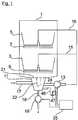
- FIG. 1is a schematic diagram of a dishwasher with washing container 1, in which a not shown items to be washed in dish racks 3, 5 can be arranged.
- two spraying arms 7, 9provided in different spraying levels are arranged by way of example as spraying devices, with which the washware to be cleaned is supplied with washing liquid.
- a pump pot 11Under the Spül maerboden a pump pot 11 is provided with associated circulating pump 13, which is fluidly connected via fluid lines 15, 16 with the spray arms 7, 9.
- the sump 11is also connected via connecting pieces with a, connected to the water supply network fresh water supply line 17, and a drain line 18 in conjunction, in which a drain pump 19 is arranged to pump out contaminated rinsing liquid from the washing.
- the pump pot 11is arranged on the upper side with a flat, funnel-shaped fine filter 21, in the center of a hollow cylindrical, cup-shaped coarse filter 22 is inserted.
- the fine filter 21 and the coarse filter 22together with one according to the Fig. 2 used in the circulating pump 13 additional filter 23, a three-part filter system.
- the sump 11is connected via a fluid line 24 with the downstream circulation pump 13 in connection.
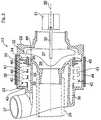
- the liquid line 24is, as in the Fig. 2 is indicated, pushed with its line end to an intake manifold 25 of the circulation pump 13, which is here for example coaxial with the central axis 26 of the circulating pump 13.
- the circulating pump 13has a rotatable about the central axis 26 paddle wheel 27 which is provided in a Schaufelradraum 28 within a pump housing 29.
- the paddle wheel 27is in drive connection via a drive shaft 30 with an only indicated electric motor 31.
- the Schaufelradraum 28is at its radially outer side via an annular gap 32 with an annular pressure chamber 33 in fluid communication.
- the pressure chamber 33extends rotationally symmetrically about the central axis 26 and radially outwardly beyond the intake manifold 25 between the Schaufelradraum 28 and the pressure chamber 33 is provided in the annular gap 32 as a flow guide 34, which is non-rotatably mounted on a bearing seat 35 of the pump housing 26.
- the helically extending baffles of the stator 34are made so steep that the inflowing rinsing liquid flows through the pressure chamber 33 in a high flow velocity in the radial circumferential direction, d. H. tangentially to the cylindrical pump housing wall 44.
- the rinsing fluid flow flowing into the pressure chamber 33has a low velocity component in the axial direction.
- an annular flow channel 36connects, through which the rinsing liquid is conveyed tangentially through an outlet-side discharge port 37 into the liquid line 14.
- the additional filter 23is arranged in the pressure chamber 33.
- the additional filter 23divides the pressure chamber 33 into a radially outer side inlet chamber 38 and into a radially inner side outlet chamber 39.
- the additional filter 23has here, by way of example, three disk-shaped filter means 40, which sit on a hollow cylindrical filter medium carrier 41, which extends in the axial direction through the pressure chamber 33.
- the filter medium carrier 41may be a pipe section whose front ends abut against opposite boundary walls 48 of the pressure chamber 33.
- the disk-shaped filter means 40are spaced with their outer edges over a free flow gap 42 of a housing outer wall 44.
- the disc-shaped filter means 40project radially outwardly into the inlet chamber 38. In the axial direction, the filter means are spaced by annular filter chambers 43 in which, if necessary, cleaning bodies are provided which remove the filter residues from the filter surface.
- an example here as Dick Mrsheizelement 45is provided which heats the circulating from the circulating pump 13 rinsing liquid.
- the rinsing liquidis sucked in by the rotating bucket wheel 27 and guided at high flow speed through the bucket wheel space 28 into the pressure space 33.
- the arranged in the pressure chamber 33 filter means 40are flowed through by appropriate flow orientation on the stator 34 in a circular cross-flow. Due to the transverse flow, residues are removed from the filter surface of the disk-shaped filter means 40 and forced outward by centrifugal action to the housing outer wall 44. The filter residues accumulate in the lower region of the housing outer wall 44.
- the filter residues in the inlet chamber 38 of the pressure chamber 33can be returned to the sump 11 by a backwash from the circulation pump 13.
- the paddle wheel 27can be actuated in a direction opposite to the direction of rotation.
- a valve-controlled drain 46 opening into the bottom region of the housing side wall 44can be provided, as described in US Pat Fig. 1 is shown.
- filter residuescan be removed from the circulation pump.
- the discharge line 46as a blocking element to a solenoid valve 47 which can be opened and closed by the control device 35.
- the derivative 46is connected to the pump pot 11.
- the control device 35can open the solenoid valve 47 simultaneously with the activation of the drain pump 19 in a cleaning operation. In this way, the filter residues collected in the pressure chamber 33 are conducted via the discharge line 46 and the pump pot 11 into the sewage system.
Landscapes
- Engineering & Computer Science (AREA)
- Mechanical Engineering (AREA)
- General Engineering & Computer Science (AREA)
- Water Supply & Treatment (AREA)
- Physics & Mathematics (AREA)
- Thermal Sciences (AREA)
- Structures Of Non-Positive Displacement Pumps (AREA)
- Washing And Drying Of Tableware (AREA)
- Filtration Of Liquid (AREA)
Description
Translated fromGermanDie Erfindung betrifft ein wasserführendes Haushaltsgerät nach dem Oberbegriff des Patentanspruches 1.The invention relates to a water-conducting household appliance according to the preamble of claim 1.
Aus der
Eine weitere Geschirrspülmaschine mit einer Umwälzvorrichtung sowie einem Filter ist beispielsweise aus der
In der
Die
Die Geschirrspülmaschine der
Bei der Geschirrspülmaschine der
Um bei wasserführenden Haushaltsgeräten, wie beispielsweise Geschirrspülmaschinen zu verhindern, dass das Leitungssystem, in dem Spülflotte umgewälzt wird, durch Schmutzpartikel verschmutzt wird, wird ein Filtersystem eingesetzt, das ein Grobsieb, ein Feinsieb und ein Mikrosieb umfassen kann. Dabei dient das Grobsieb dazu, Schmutzpartikel zurückzuhalten, die zu einer Blockade der Laugenpumpe führen können. Mit einem Feinsieb werden Partikel mit einer Partikelgröße größer ca. 1 mm und mit einem Mikrosieb werden Partikel mit einer Partikelgröße größer ca. 0,15 mm zurückgehalten.In order to prevent water in household appliances, such as dishwashers, that the conduit system is circulated in the wash liquor is polluted by dirt particles, a filter system is used, which may include a coarse filter, a fine sieve and a micro sieve. The coarse screen is used to retain dirt particles that can lead to a blockage of the drain pump. With a fine sieve, particles with a particle size greater than approx. 1 mm are retained and with a micro sieve particles with a particle size greater than approx. 0.15 mm are retained.
Ein wasserführendes Haushaltsgerät wie z.B. eine Geschirrspülmaschine weist eine Laugenpumpe auf, mit der am Ende eines Spülgangs verschmutzte Spülflotte aus dem Geschirrspüler heraus in ein hausseitiges Abwasserentsorgungssystem gefördert werden kann. Derartige Laugenpumpen sind derart ausgelegt, dass sie größere Partikelgrößen ungehindert fördern können und es zu keiner Blockade der Laugenpumpe kommt. Daher sind Laugenpumpen derart angeordnet, dass verschmutzte Spülflotte bei Abpumpen nur grob gefiltert wird.A water-conducting household appliance such. a dishwashing machine has a drain pump, with which at the end of a wash cycle soiled wash liquor can be conveyed out of the dishwasher into a house-side wastewater disposal system. Such lye pumps are designed so that they can promote larger particle sizes unhindered and there is no blockage of the drain pump. Therefore, lye pumps are arranged in such a way that polluted rinsing liquor is only roughly filtered during pumping.
Ferner weist eine Geschirrspülmaschine eine Umwälzpumpe auf, mit der während eines Reinigungsvorgangs Spülflotte umgewälzt werden kann, d.h., sich im Pumpensumpf einer Geschirrspülmaschine sammelnde Flüssigkeit wird mittels der Umwälzpumpe durch ein Hydrauliksystem im Inneren des Spülbehälters angeordneten Sprüharmen zugeführt, mit denen eine gleichmäßige Beaufschlagung des Spülguts mit Spülflotte erfolgt. Die Sprüharme weisen verhältnismäßig kleine Öffnungen auf, sodass es erforderlich ist, die umgewälzte Spülflotte durch das Fein- und Mikrosieb zu führen, damit auch kleinste Partikel zurückgehalten werden und die Austrittsöffnungen der Sprüharme nicht verstopfen können. Entsprechend ist die Umwälzpumpe bezüglich der Partikelgrößentoleranz ausgebildet.Furthermore, a dishwasher has a circulation pump with which rinsing liquor can be circulated during a cleaning operation, ie, in the sump of a dishwasher collecting liquid is supplied by the circulation pump by a hydraulic system in the interior of the Spülbehälters arranged spray arms, with which a uniform loading of the dishes with Rinsing carried out. The spray arms have relatively small openings, so it is necessary to guide the circulated rinsing liquor through the fine and micro sieve, so that even the smallest particles are retained and the outlet openings of the spray arms can not clog. Accordingly, the circulation pump is designed with respect to the particle size tolerance.
Die Aufgabe der Erfindung besteht darin, ein wasserführendes Haushaltsgerät, insbesondere eine Geschirrspül- oder Waschmaschine, bereitzustellen, deren Filter eine gesteigerte Zuverlässigkeit aufweisen.The object of the invention is to provide a water-conducting domestic appliance, in particular a dishwasher or washing machine, whose filters have an increased reliability.
Die Aufgabe der Erfindung ist durch die Merkmale des Patentanspruches 1 gelöst. Vorteilhafte Weiterbildungen der Erfindung sind in den Unteransprüchen offenbart.The object of the invention is solved by the features of claim 1. Advantageous developments of the invention are disclosed in the subclaims.
Die Erfindung geht aus von einem wasserführendes Haushaltsgerät, insbesondere Geschirrspül- oder Waschmaschine, mit einem Hydraulikkreislauf, in dem Spülflüssigkeit umwälzbar ist und in dem wenigstens ein Zusatzfilter zur Filterung umgewälzter Spülflotte vorgesehen ist. Die erfindungsgemäße Lösung ist dadurch gekennzeichnet, dass in dem Hydraulikkreislauf wenigstens ein Zusatzfilter zur Filterung umgewälzte Spülflotte vorgesehen ist, das in einem Bereich des Hydraulikkreislaufs angeordnet ist, in dem umgewälzte Spülflotte eine Rotation aufweist. Die Rotation der umgewälzten Spülflotte bzw. ihre turbulente Strömung bewirkt dabei, das sich die Filterfläche des Zusatzfilter nicht durch Filterkuchenbildung zusetzt, sondern einen ungehinderter Durchtritt von Spülflüssigkeit bzw. Spülflotte gewährleistet ist. Dabei kann es sich um eine vollständige Rotation oder nur um eine abschnittweise kreis- bzw. bogenförmige Dreh- bzw. Umlenkbewegung handeln, die bspw. durch Umlenkmittel wie Leitbleche oder eine Kanalführung hervorgerufen wird.The invention is based on a water-conducting domestic appliance, in particular dishwashing or washing machine, with a hydraulic circuit in which rinsing liquid can be recirculated and in which at least one additional filter is provided for filtering circulated rinsing liquor. The solution according to the invention is characterized in that at least one additional filter for filtering circulated rinsing liquor is provided in the hydraulic circuit, which is arranged in a region of the hydraulic circuit in which recirculated rinsing fluid has a rotation. The rotation of the circulating rinsing liquor or its turbulent flow in this case causes the filter surface of the additional filter is not clogged by forming a filter cake, but an unhindered passage of rinsing liquid or rinsing liquor is guaranteed. This may be a complete rotation or only a partially circular or arcuate rotary or deflection movement, which is caused, for example, by deflecting means such as baffles or a channel guide.
Hierzu sind erfindungsgemäß in dem Bereich des Hydraulikkreislaufs eine Rotation umgewälzter Spülflotte erzeugende Mittel vorgesehen. Es kann sich hierbei um ortsfeste Leitbleche oder -schaufeln handeln, die strömender Spülflüssigkeit eine Rotation aufprägen. Jedoch ist erfindungsgemäß vorgesehen, dass die eine Rotation umgewälzter Spülflotte erzeugende Mittel eine Umwälzpumpe zur Umwälzung von Spülflüssigkeit umfassen.For this purpose, according to the invention, a rotation of circulated rinsing liquor generating means is provided in the area of the hydraulic circuit. These may be stationary baffles or vanes that impart rotation to flowing rinse liquid. However, it is provided according to the invention that the means for generating a rotation of circulated rinsing agent comprise a circulating pump for circulating rinsing liquid.
Erfindungsgemäß ist vorgesehen, dass in der Umwälzpumpe das Zusatzfilter angeordnet ist. Gegebenenfalls kann somit die üblicher Weise vorgesehene Filterkombination in der Geschirrspülmaschine um den Zusatzfilter erweitert werden. Alternativ kann auch auf einen, im Pumpentopf angeordneten Filter verzichtet werden, wodurch der Pumpentopf kleiner dimensionierbar ist und damit auch die zu erwärmende Totwassermenge im Pumpentopf vorteilig reduzierbar ist.According to the invention, it is provided that the additional filter is arranged in the circulation pump. Optionally, thus the usual way provided filter combination can be extended in the dishwasher to the additional filter. Alternatively, it is also possible to dispense with a filter arranged in the pump pot, as a result of which the pump pot can be made smaller and thus also the amount of dead water to be heated in the pump pot can advantageously be reduced.
Dem Zusatzfilter ist in Strömungsrichtung der Spülflüssigkeit die im Pumpentopf angeordnete Siebkombination vorgelagert, die zumindest eine Grob- und/oder Feinfiltration vornehmen kann. Die dem Zusatzfilter zugeführte Spülflüssigkeit ist somit bereits vorgeklärt, so dass der Zusatzfilter als ein Mikrofilter ausführbar ist, der speziell zur Abfilterung von im Wasser fein dispergierten Schmutzpartikeln ausgelegt ist.The additional filter is preceded by the sieve combination arranged in the sump in the flow direction of the rinsing liquid, which can carry out at least one coarse and / or fine filtration. The rinsing liquid supplied to the additional filter is thus already precleared, so that the additional filter can be embodied as a microfilter, which is specially designed for filtering off dirt particles which are finely dispersed in the water.
Das Pumpengehäuse der Umwälzpumpe weist erfindungsgemäß einen Schaufelradraum mit einem die Spülflüssigkeit fördernden Schaufelrad und einen stromab davon angeordneten Druckraum auf, in den die vom Schaufelrad geförderte Spülflüssigkeit in hoher Strömungsgeschwindigkeit einströmt. Der Druckraum kann in Strömungsrichtung in einen Strömungskanal übergehen, der die Spülflüssigkeit zu einem auslassseitigen Druckstutzen der Umwälzpumpe führt. Erfindungsgemäß ist der Zusatzfilter im Druckraum angeordnet, wodurch dessen Filteroberfläche auf Grund der hohen Turbulenzen der in den Druckraum einströmenden Spülflüssigkeit ständig freigespült wird und damit nicht von Filterrückständen zugesetzt werden kann.According to the invention, the pump housing of the circulating pump has a paddle wheel space with a paddle wheel conveying the rinsing fluid and a pressure chamber arranged downstream thereof, into which the rinsing fluid delivered by the paddle wheel flows in a high flow rate. The pressure chamber can transition in the flow direction into a flow channel, which leads the rinsing liquid to an outlet-side discharge nozzle of the circulation pump. According to the additional filter is arranged in the pressure chamber, whereby the filter surface is constantly flushed due to the high turbulence of the inflowing into the pressure chamber rinsing liquid and thus can not be added by filter residues.
Der Druckraum erstreckt sich erfindungsgemäß ringförmig um eine Mittelachse der Umwälzpumpe. Bei einer entsprechenden Strömungsausrichtung kann die Spülflüssigkeit den Druckraum in einer Rotationsbewegung, d. h. tangential zu einer den Druckraum begrenzenden Pumpengehäusewand, durchströmen. Die Strömungsrichtung kann entsprechend durch ein erfindungsgemäß zwischen dem Schaufelradraum und dem Druckraum geschaltetes Strömungsleitelement, etwa ein Leitrad, entsprechend in Umfangsrichtung ausgelegt werden. Eine solche kreisförmige Querströmung im Druckraum gewährleistet eine erhöhte Verweildauer der Spülflüssigkeit im Druckraum sowie eine vollständige Überströmung der gesamten Filteroberfläche des Zusatzfilters.The pressure chamber according to the invention extends annularly around a central axis of the circulation pump. With a corresponding flow orientation, the rinsing liquid can move the pressure space in a rotational movement, i. H. tangential to a pressure chamber bounding the pump housing wall, flow through. The flow direction can be correspondingly designed by a according to the invention between the Schaufelradraum and the pressure chamber flow guide, such as a stator, according to the circumferential direction. Such a circular cross-flow in the pressure chamber ensures an increased residence time of the rinsing liquid in the pressure chamber and a complete overflow of the entire filter surface of the additional filter.
Für eine hohe Filterleistung ist eine vollständige Durchströmung der umgewälzten Spülflüssigkeit durch den Zusatzfilter zu gewährleisten. Hierzu kann der durchströmte Druckraum vom Zusatzfilter erfindungsgemäß in eine Einlasskammer, in der die Spülflüssigkeit einströmt, und in eine Auslasskammer aufgeteilt werden, aus der die Spülflüssigkeit zu einem auslassseitigen Druckstutzen der Umwälzpumpe strömt. Strömungstechnisch günstig ist es, wenn die Einlasskammer des Druckraums mit Bezug auf die Mittelachse der Umwälzpumpe radial außerhalb der Auslasskammer des Druckraums liegt. Die Spülflüssigkeit kann somit in Rotationsbewegung entlang einer radialen Außenwandung des Pumpengehäuses den Zusatzfilter überströmen.For a high filter performance, a complete flow through the circulating rinsing liquid through the additional filter is to be ensured. For this purpose, the flow-through pressure chamber from the additional filter according to the invention in an inlet chamber in which the rinsing liquid flows, and are divided into an outlet chamber from which the rinsing liquid flows to an outlet side discharge nozzle of the circulation pump. In terms of flow technology, it is favorable if the inlet chamber of the pressure chamber is located radially outside the outlet chamber of the pressure chamber with respect to the center axis of the circulation pump. The flushing liquid can thus flow over the additional filter in rotational movement along a radial outer wall of the pump housing.
Zur weiteren Steigerung der Filterleistung ist es von Vorteil, wenn der Zusatzfilter zumindest ein, vorzugsweise scheibenförmiges Filtermittel aufweist, dass auf einem hohl zylindrischen Filtermittel-Träger sitzt, der den Druckraum in die bereits erwähnten Einlass- und Auslasskammer aufteilt. Für eine möglichst große Filteroberfläche kann das auf dem Filtermittel-Träger vorgesehene Filtermittel in die Einlasskammer einragen. Der Außenrand des Filtermittels ist hierbei bevorzugt jedoch nicht in Anlage mit einer radial gegenüberliegenden Pumpengehäuse-Wandung, sondern von dieser über einen Strömungsspalt beabstandet, um eine größtmögliche Umströmung des Filtermittels zu gewährleisten.To further increase the filter performance, it is advantageous if the additional filter has at least one, preferably disc-shaped filter means that on a hollow cylindrical filter medium carrier sits, which divides the pressure chamber in the aforementioned inlet and outlet chamber. For the largest possible filter surface, the filter medium provided on the filter medium carrier can protrude into the inlet chamber. However, the outer edge of the filter means is preferably not in contact with a radially opposite pump housing wall, but spaced therefrom by a flow gap in order to ensure the greatest possible flow around the filter medium.
Bevorzugt sitzen eine Anzahl von über Filterräume beabstandete Filtermittel auf dem hohlzylindrischen Filtermittel-Träger. Die scheibenförmigen Filtermittel erstrecken sich daher zusammen mit diesen Filterräumen ringförmig um die Mittelachse der Umwälzpumpe innerhalb des Druckraums. Bei einer in Rotationsbewegung durch den Druckraum geführten Flüssigkeitsströmung erfolgt daher innerhalb dieser Filterräume eine großflächige Überströmung der Filteroberflächen, wodurch die Filteroberflächen ständig freigespült bleiben und Filterrückstände die Filteroberflächen nicht zusetzen können. Die Reinigung des Zusatzfilters, d. h. die Reinigung der dem Zusatzfilter vorgelagerten Einlasskammer kann durch eine Strömungsumkehr bzw. einen Rückspülen von Spülflüssigkeit erfolgen, wodurch die Filterrückstände in den Pumpentopf rückgeführt werden. Alternativ können die sich an einer Seitenwand des Druckraumes sammelnden Filterrückstände über einen separaten, ventilgesteuerten Kanal in den Pumpentopf abgeleitet werden, von wo sie mittels einer Laugenpumpe in das Abwassersystem geleitet werden können. Zur Unterstützung einer Abtragung von, die Filteroberflächen der Filtermittel zusetzenden Rückstände kann in den oben erwähnten Filterräumen zumindest ein frei bewegbarer Reinigungskörper vorgesehen sein, der durch die kreisförmige Querströmung der Spülflüssigkeit frei in den Filterräumen bewegbar ist.Preferably, a number of filter media spaced filter media sit on the hollow cylindrical filter media carrier. The disc-shaped filter means therefore extend together with these filter spaces in an annular manner about the center axis of the circulation pump within the pressure chamber. In a guided in rotational movement through the pressure chamber liquid flow therefore takes place within these filter chambers, a large surface overflow of the filter surfaces, whereby the filter surfaces are constantly flushed and filter residues can not clog the filter surfaces. The cleaning of the additional filter, d. H. the cleaning of the additional filter upstream inlet chamber can be done by a flow reversal or a backwashing of rinsing liquid, whereby the filter residues are returned to the sump. Alternatively, the filter residues collecting on a side wall of the pressure chamber can be discharged into the pump pot via a separate, valve-controlled channel, from where they can be conducted into the sewage system by means of a drain pump. To support a removal of, the filter surfaces zusetzenenden filter residues can be provided in the above-mentioned filter spaces at least one freely movable cleaning body, which is freely movable in the filter chambers by the circular cross-flow of the rinsing liquid.
In einer bevorzugten Ausführungsform ist dem Druckraum der Umwälzpumpe ein Heizelement zur Erwärmung der Spülflüssigkeit zugeordnet. In der Druckkammer ist somit nicht nur der Zusatzfilter angeordnet sondern wird darüber hinaus in Doppelfunktion auch die Spülflüssigkeit erwärmt. Insbesondere auf Grund der hohen Turbulenzen der mit hoher Strömungsgeschwindigkeit in den Druckraum einströmenden Spülflüssigkeit wird die im Hydraulikkreislauf umgewälzte Spülflüssigkeit im Druckraum beschleunigt erwärmt.In a preferred embodiment, the pressure chamber of the circulation pump is assigned a heating element for heating the rinsing liquid. In the pressure chamber thus not only the additional filter is arranged but also in dual function beyond heats the rinsing liquid. In particular, due to the high turbulence of the high flow rate flowing into the pressure chamber rinsing liquid, the circulating in the hydraulic circuit rinsing liquid is heated accelerated in the pressure chamber.
Nachfolgend ist ein Ausführungsbeispiel der Erfindung anhand der beigefügten Figuren beschrieben.Hereinafter, an embodiment of the invention with reference to the accompanying figures will be described.
Es zeigen:
- Fig. 1
- in einem schematischen Blockdiagramm eine erfindungsgemäße Geschirrspülmaschine; und
- Fig. 2
- in einer Seitenschnittdarstellung einen Hydraulikkreislauf der Geschirrspülmaschine verwendete Umwälzpumpe.
- Fig. 1
- in a schematic block diagram of a dishwasher according to the invention; and
- Fig. 2
- in a side sectional view of a hydraulic circuit of the dishwasher used circulating pump.
In der
Wie in der
Der Pumpentopf 11 ist über eine Flüssigkeitsleitung 24 mit der nachgeschalteten Umwälzpumpe 13 in Verbindung. Die Flüssigkeitsleitung 24 ist, wie es in der
Der Schaufelradraum 28 ist an seiner radial äußeren Seite über einen Ringspalt 32 mit einem ringförmigen Druckraum 33 in Strömungsverbindung. Der Druckraum 33 erstreckt sich rotationssymetrisch um die Mittelachse 26 sowie radial außerhalb über den Ansaugstutzen 25. Zwischen dem Schaufelradraum 28 und dem Druckraum 33 ist in dem Ringspalt 32 als Strömungsleitelement ein Leitrad 34 vorgesehen, das drehfest auf einem Lagersitz 35 des Pumpengehäuses 26 sitzt. Die schraubenlinienförmig verlaufenden Leitwände des Leitrades 34 sind derart steil angestellt, dass die einströmende Spülflüssigkeitsströmung in hoher Strömungsgeschwindigkeit in radialer Umfangsrichtung die Druckkammer 33 durchströmt, d. h. tangential zur zylindrischen Pumpengehäuse-Wand 44. Dementsprechend weist die in den Druckraum 33 einströmende Spülflüssigkeitsströmung eine geringe Geschwindigkeitskomponente in Axialrichtung auf. Stromab der Druckkammer 33 schließt sich ein ringförmiger Strömungskanal 36 an, durch den die Spülflüssigkeit tangential durch einen auslassseitigen Druckstutzen 37 in die Flüssigkeitsleitung 14 gefördert wird.The
Wie bereits oben erwähnt, ist in dem Druckraum 33 der Zusatzfilter 23 angeordnet. Der Zusatzfilter 23 teilt den Druckraum 33 in eine radialaußenseitige Einlasskammer 38 und in eine radial innenseitige Auslasskammer 39 auf. Der Zusatzfilter 23 weist hier beispielhaft drei scheibenförmige Filtermittel 40 auf, die auf einem hohlzylindrischen Filtermittel-Träger 41 sitzen, der sich in Axialrichtung durch den Druckraum 33 erstreckt. Der FiltermittelTräger 41 kann ein Rohrabschnitt sein, dessen stirnseitige Enden an gegenüberliegenden Begrenzungswänden 48 des Druckraums 33 anliegen. Die scheibenförmigen Filtermittel 40 sind mit ihren Außenrändern über einen freien Strömungsspalt 42 von einer Gehäuseaußenwand 44 beabstandet.As already mentioned above, the
Die scheibenförmigen Filtermittel 40 ragen in Radialrichtung nach außen in die Einlasskammer 38 ein. In der Axialrichtung sind die Filtermittel über ringförmige Filterräume 43 beabstandet, in denen ggf. Reinigungskörper vorgesehen sind, die Filterrückstände von der Filteroberfläche abtragen.The disc-shaped filter means 40 project radially outwardly into the inlet chamber 38. In the axial direction, the filter means are spaced by
Wie aus der
Während eines Umwälzbetriebes wird die Spülflüssigkeit vom rotierenden Schaufelrad 27 angesaugt und mit hoher Strömungsgeschwindigkeit durch den Schaufelradraum 28 in den Druckraum 33 geführt. Die im Druckraum 33 angeordneten Filtermittel 40 werden durch entsprechende Strömungsausrichtung am Leitrad 34 in einer kreisförmigen Querströmung überströmt. Durch die Querströmung werden Rückstände von der Filteroberfläche der scheibenförmigen Filtermittel 40 abgetragen und durch Zentrifugalwirkung nach außen an die Gehäuseaußenwand 44 gedrängt. Die Filterrückstände sammeln sich dabei im unteren Bereich der Gehäuseaußenwand 44.During a circulation operation, the rinsing liquid is sucked in by the
Die Filterrückstände in der Einlasskammer 38 des Druckraums 33 können durch eine Rückspülung von der Umwälzpumpe 13 in den Pumpentopf 11 rückgeführt werden. Hierzu kann das Schaufelrad 27 in einer zur Förderrichtung entgegengesetzten Drehrichtung betätigt werden.The filter residues in the inlet chamber 38 of the
Alternativ zur Rückspülung kann eine in den Bodenbereich der Gehäuseseitenwand 44 mündende, ventilgesteuerte Ableitung 46 bereitgestellt werden, wie sie in der
Claims (11)
- Water conducting household appliance, in particular a dishwasher or washing machine, having a hydraulic circuit, in which washing fluid can be circulated and in which at least one additional filter (23) is provided to filter circulated washing liquor, wherein at least one additional filter (23) for filtering circulated washing liquor is provided in the hydraulic circuit and is disposed in a region of the hydraulic circuit, in which circulated washing liquor is rotated, wherein means generating a rotation of circulated washing liquor are provided in the region of the hydraulic circuit, said means comprising a circulation pump (13) to circulate washing fluid, in which the additional filter (23) is disposed and which has an impeller chamber (28) with an impeller (27) that conveys the washing fluid and a pressure chamber (33) disposed downstream therefrom, wherein the additional filter (23) is disposed in the pressure chamber (33), wherein the additional filter (23) divides the pressure chamber (33) into an inlet chamber (38), into which the washing fluid flows, and an outlet chamber (39), from which the washing fluid flows to an outlet-side pressure connection (37) of the circulation pump (13) and wherein the pressure chamber (33) and/or the inlet chamber (38) and the outlet chamber (39) extend in an annular manner about the centre axis (26) of the circulation pump (13),characterised in that the inlet chamber (38) of the pressure chamber (33) is located radially outside the outlet chamber (39) of the pressure chamber (33) in relation to a centre axis (26) of the circulation pump (13), a flow routing element (34) is connected between the impeller chamber (28) and the pressure chamber (33) and the flow routing element (34) introduces the washing fluid tangentially along a pump housing wall (44).
- Water conducting household appliance according to claim 1,characterised in that a pump sump (11) is connected upstream of the circulation pump (13) with a coarse and/or fine filter (21, 22) disposed therein.
- Water conducting household appliance according to claim 2,characterised in that the coarse and/or fine filter (21, 22) has/have a bigger mesh width than the additional filter (23).
- Water conducting household appliance according to one of claims 1 to 3,characterised in that the additional filter (23) has at least one, preferably disk-shaped filter means (40), which is positioned on a hollow cylindrical filter means support (41), which divides the pressure chamber (33) into the inlet and outlet chambers (38, 39).
- Water conducting household appliance according to claim 4,characterised in that the hollow cylindrical filter means support (41) extends coaxially to the circulation pump centre axis (26) between opposing boundary walls (43) of the pressure chamber (33).
- Water conducting household appliance according to claim 4 or 5,characterised in that the filter means (40) project into the inlet chamber (38) and at least one filter chamber (43) is bounded between the filter means (40) or housing walls, preferably extending in an annular manner about the centre axis (26) of the circulation pump (13).
- Water conducting household appliance according to claim 4,5 or 6,characterised in that the filter means (40) is kept at a radial distance from a pump housing wall (44) in a radial direction outward by way of a flow gap (42).
- Water conducting household appliance according to claim 6 or 7,characterised in that at least one preferably freely movable cleaning unit is disposed in the filter chamber (43).
- Water conducting household appliance according to one of claims 1 to 8,characterised in that a heating element (44) for heating the washing fluid is assigned to the pressure chamber (33) of the circulation pump (13).
- Water conducting household appliance according to one of the preceding claims 1 to 9,characterised in that the circulation pump (13) is connected to a pump sump (11) by way of a discharge line (46).
- Water conducting household appliance according to claim 10,characterised in that a blocking element (47) is disposed in the discharge line (46), which preferably opens the discharge line (46) when a washing liquor pump (19) discharges washing fluid from the pump sump (11).
Applications Claiming Priority (2)
| Application Number | Priority Date | Filing Date | Title |
|---|---|---|---|
| DE102007060193ADE102007060193A1 (en) | 2007-12-14 | 2007-12-14 | Water-conducting household appliance |
| PCT/EP2008/065292WO2009077266A1 (en) | 2007-12-14 | 2008-11-11 | Water conducting household appliance |
Publications (2)
| Publication Number | Publication Date |
|---|---|
| EP2230985A1 EP2230985A1 (en) | 2010-09-29 |
| EP2230985B1true EP2230985B1 (en) | 2016-06-15 |
Family
ID=40340478
Family Applications (1)
| Application Number | Title | Priority Date | Filing Date |
|---|---|---|---|
| EP08861330.2AActiveEP2230985B1 (en) | 2007-12-14 | 2008-11-11 | Water conducting household appliance |
Country Status (6)
| Country | Link |
|---|---|
| US (1) | US8733375B2 (en) |
| EP (1) | EP2230985B1 (en) |
| CN (1) | CN101896112B (en) |
| DE (1) | DE102007060193A1 (en) |
| PL (1) | PL2230985T3 (en) |
| WO (1) | WO2009077266A1 (en) |
Families Citing this family (52)
| Publication number | Priority date | Publication date | Assignee | Title |
|---|---|---|---|---|
| US8746261B2 (en) | 2009-12-21 | 2014-06-10 | Whirlpool Corporation | Rotating drum filter for a dishwashing machine |
| US8627832B2 (en) | 2010-12-13 | 2014-01-14 | Whirlpool Corporation | Rotating filter for a dishwashing machine |
| US8667974B2 (en) | 2009-12-21 | 2014-03-11 | Whirlpool Corporation | Rotating filter for a dishwashing machine |
| US9687135B2 (en) | 2009-12-21 | 2017-06-27 | Whirlpool Corporation | Automatic dishwasher with pump assembly |
| US9119515B2 (en) | 2010-12-03 | 2015-09-01 | Whirlpool Corporation | Dishwasher with unitary wash module |
| US9918609B2 (en) | 2009-12-21 | 2018-03-20 | Whirlpool Corporation | Rotating drum filter for a dishwashing machine |
| DE102010028619A1 (en)* | 2010-05-05 | 2011-11-10 | BSH Bosch und Siemens Hausgeräte GmbH | Valve, domestic appliance and method of operating a valve |
| US9113766B2 (en) | 2010-11-16 | 2015-08-25 | Whirlpool Corporation | Method and apparatus for dishwasher with common heating element for multiple treating chambers |
| US9668636B2 (en) | 2010-11-16 | 2017-06-06 | Whirlpool Corporation | Method and apparatus for dishwasher with common heating element for multiple treating chambers |
| US9034112B2 (en) | 2010-12-03 | 2015-05-19 | Whirlpool Corporation | Dishwasher with shared heater |
| EP2654543B1 (en)* | 2010-12-24 | 2020-04-29 | Arçelik Anonim Sirketi | A dishwasher comprising a storage tank |
| US8733376B2 (en) | 2011-05-16 | 2014-05-27 | Whirlpool Corporation | Dishwasher with filter assembly |
| US9107559B2 (en) | 2011-05-16 | 2015-08-18 | Whirlpool Corporation | Dishwasher with filter assembly |
| US20120318296A1 (en) | 2011-06-20 | 2012-12-20 | Whirlpool Corporation | Ultra micron filter for a dishwasher |
| US9005369B2 (en) | 2011-06-20 | 2015-04-14 | Whirlpool Corporation | Filter assembly for a dishwasher |
| US9265401B2 (en) | 2011-06-20 | 2016-02-23 | Whirlpool Corporation | Rotating filter for a dishwashing machine |
| US9010344B2 (en) | 2011-06-20 | 2015-04-21 | Whirlpool Corporation | Rotating filter for a dishwashing machine |
| US9861251B2 (en) | 2011-06-20 | 2018-01-09 | Whirlpool Corporation | Filter with artificial boundary for a dishwashing machine |
| DE102011079510B4 (en)* | 2011-07-20 | 2016-11-24 | E.G.O. Elektro-Gerätebau GmbH | pump |
| DE102011079887A1 (en)* | 2011-07-27 | 2013-01-31 | BSH Bosch und Siemens Hausgeräte GmbH | Water-conducting domestic appliance has tubular heating body arranged and formed as electrical heating unit in heating space housing section such that axial flow component is imposed by dishwashing liquid flow |
| US9693672B2 (en) | 2011-09-22 | 2017-07-04 | Whirlpool Corporation | Dishwasher with sprayer |
| DE102012200113B4 (en) | 2012-01-05 | 2016-07-07 | BSH Hausgeräte GmbH | Heating device in a water-conducting household appliance |
| US9307885B2 (en) | 2012-01-11 | 2016-04-12 | Whirlpool Corporation | Rotating filter assembly for a dishwasher |
| DE102012202491B3 (en)* | 2012-02-17 | 2013-08-08 | E.G.O. Elektro-Gerätebau GmbH | Guide wheel for an impeller pump and impeller pump |
| US9301667B2 (en) | 2012-02-27 | 2016-04-05 | Whirlpool Corporation | Soil chopping system for a dishwasher |
| US9730570B2 (en) | 2012-05-30 | 2017-08-15 | Whirlpool Corporation | Reduced sound with a rotating filter for a dishwasher |
| US9237836B2 (en) | 2012-05-30 | 2016-01-19 | Whirlpool Corporation | Rotating filter for a dishwasher |
| US9451862B2 (en) | 2012-06-01 | 2016-09-27 | Whirlpool Corporation | Dishwasher with unitary wash module |
| US9833120B2 (en) | 2012-06-01 | 2017-12-05 | Whirlpool Corporation | Heating air for drying dishes in a dishwasher using an in-line wash liquid heater |
| US9532700B2 (en) | 2012-06-01 | 2017-01-03 | Whirlpool Corporation | Dishwasher with overflow conduit |
| US9554688B2 (en) | 2012-10-23 | 2017-01-31 | Whirlpool Corporation | Rotating filter for a dishwasher and methods of cleaning a rotating filter |
| US20140158168A1 (en)* | 2012-12-12 | 2014-06-12 | General Electric Company | Sump assembly for a dishwasher appliance |
| DE102013200280A1 (en)* | 2013-01-10 | 2014-07-10 | E.G.O. Elektro-Gerätebau GmbH | impeller |
| US9532701B2 (en) | 2013-03-01 | 2017-01-03 | Whirlpool Corporation | Dishwasher with sprayer |
| DE102013211556A1 (en)* | 2013-06-19 | 2014-12-24 | E.G.O. Elektro-Gerätebau GmbH | Heating device for a pump and pump |
| US9713413B2 (en) | 2013-07-01 | 2017-07-25 | Whirlpool Corporation | Dishwasher for treating dishes |
| US9532699B2 (en) | 2013-07-15 | 2017-01-03 | Whirlpool Corporation | Dishwasher with sprayer |
| DE102014201880B3 (en)* | 2014-02-03 | 2014-12-18 | Schaeffler Technologies Gmbh & Co. Kg | Dirt trap as a functional module in the impeller of a coolant pump |
| ES1110956Y (en) | 2014-03-10 | 2014-08-29 | Coprecitec Sl | Recirculated and drained pump for an appliance, in particular a washing machine or a domestic dishwasher |
| DE102016201975B3 (en)* | 2016-02-10 | 2017-03-02 | BSH Hausgeräte GmbH | Laundry care unit with a pump |
| DE102016203179B3 (en)* | 2016-02-29 | 2017-05-11 | BSH Hausgeräte GmbH | Laundry care unit with a pump |
| CN206035897U (en)* | 2016-04-11 | 2017-03-22 | 广东顺德思客乐施电器科技有限公司 | Distinguish dish washer water pump in impeller cavity and heating chamber |
| DE102016208020A1 (en)* | 2016-05-10 | 2017-11-16 | BSH Hausgeräte GmbH | Liquid heating pump for conveying and heating liquid in a water-conducting domestic appliance |
| DE102016215266A1 (en) | 2016-08-16 | 2018-02-22 | BSH Hausgeräte GmbH | Assembly, in particular heating pump, with a heatable pipe section for a water-conducting household appliance, as well as water-conducting household appliance with such a unit |
| CN106762846A (en)* | 2016-12-14 | 2017-05-31 | 衡阳市力源动力制造有限公司 | A kind of cooling body with sediment prevention device |
| CN107641940B (en)* | 2017-10-23 | 2019-10-25 | 无锡小天鹅电器有限公司 | Pump body device and washing machine |
| DE102019201845A1 (en)* | 2019-02-13 | 2020-08-13 | BSH Hausgeräte GmbH | Household appliance for treating laundry |
| DE102019203809B3 (en)* | 2019-03-20 | 2020-07-02 | E.G.O. Elektro-Gerätebau GmbH | Water-bearing household appliance and method for its operation |
| DE102019205919B4 (en)* | 2019-04-25 | 2022-12-15 | E.G.O. Elektro-Gerätebau GmbH | Water-bearing domestic appliance and method for its operation |
| DE102020106792A1 (en) | 2020-03-12 | 2021-09-16 | Illinois Tool Works Inc. | DISHWASHER WITH AT LEAST ONE WASHING SYSTEM TRAINED AS A RECIRCULATION CIRCUIT |
| CN114197174B (en)* | 2020-09-18 | 2023-07-14 | 合肥美的洗衣机有限公司 | Washing machine |
| CN113153760B (en)* | 2021-06-09 | 2022-08-09 | 安徽埃斯克制泵有限公司 | Non-blocking high suction lift self-sucking pump |
Citations (2)
| Publication number | Priority date | Publication date | Assignee | Title |
|---|---|---|---|---|
| US2802477A (en)* | 1956-08-29 | 1957-08-13 | Whirlpool Seeger Corp | Combined dishwashing machine and disposal unit |
| US3129711A (en)* | 1960-09-29 | 1964-04-21 | Gorman Rupp Ind Inc | Dishwasher recirculating assembly |
Family Cites Families (9)
| Publication number | Priority date | Publication date | Assignee | Title |
|---|---|---|---|---|
| US3836001A (en)* | 1972-07-19 | 1974-09-17 | Westinghouse Electric Corp | Pump with self-cleaning lint filter |
| US3949579A (en) | 1973-02-13 | 1976-04-13 | Attilio Bertoldi | Apparatus for fabric processing |
| DE8318398U1 (en)* | 1983-06-24 | 1983-10-06 | Bosch-Siemens Hausgeraete Gmbh, 7000 Stuttgart | LYE PUMP FOR A WASHING MACHINE |
| US5601600A (en) | 1995-09-08 | 1997-02-11 | Conceptus, Inc. | Endoluminal coil delivery system having a mechanical release mechanism |
| KR970010423B1 (en)* | 1995-09-19 | 1997-06-26 | 엘지전자 주식회사 | Disposal method of dish washer and its device |
| DE19636014B4 (en)* | 1995-11-24 | 2006-03-02 | AEG Hausgeräte GmbH | Apparatus and method for filtering a liquid |
| US6418943B1 (en)* | 1999-06-04 | 2002-07-16 | Whirlpool Corporation | Wash liquid circulation system for a dishwasher |
| DE102004060950A1 (en) | 2004-12-17 | 2006-06-29 | BSH Bosch und Siemens Hausgeräte GmbH | Dishwasher with low-maintenance sieve system |
| US7985300B2 (en)* | 2005-04-04 | 2011-07-26 | Lg Electronics Inc. | Dishwasher and assembly method thereof |
- 2007
- 2007-12-14DEDE102007060193Apatent/DE102007060193A1/ennot_activeWithdrawn
- 2008
- 2008-11-11EPEP08861330.2Apatent/EP2230985B1/enactiveActive
- 2008-11-11CNCN200880120780.6Apatent/CN101896112B/enactiveActive
- 2008-11-11WOPCT/EP2008/065292patent/WO2009077266A1/enactiveApplication Filing
- 2008-11-11USUS12/745,695patent/US8733375B2/enactiveActive
- 2008-11-11PLPL08861330.2Tpatent/PL2230985T3/enunknown
Patent Citations (2)
| Publication number | Priority date | Publication date | Assignee | Title |
|---|---|---|---|---|
| US2802477A (en)* | 1956-08-29 | 1957-08-13 | Whirlpool Seeger Corp | Combined dishwashing machine and disposal unit |
| US3129711A (en)* | 1960-09-29 | 1964-04-21 | Gorman Rupp Ind Inc | Dishwasher recirculating assembly |
Also Published As
| Publication number | Publication date |
|---|---|
| CN101896112B (en) | 2012-11-28 |
| CN101896112A (en) | 2010-11-24 |
| PL2230985T3 (en) | 2016-11-30 |
| DE102007060193A1 (en) | 2009-06-25 |
| US8733375B2 (en) | 2014-05-27 |
| EP2230985A1 (en) | 2010-09-29 |
| WO2009077266A1 (en) | 2009-06-25 |
| US20100252081A1 (en) | 2010-10-07 |
Similar Documents
| Publication | Publication Date | Title |
|---|---|---|
| EP2230985B1 (en) | Water conducting household appliance | |
| DE102007061038B4 (en) | Water-conducting household appliance | |
| DE102007060197B4 (en) | Water-conducting household appliance | |
| EP1835840B1 (en) | Multi-tank dishwasher comprising a backwash device | |
| DE4131914C2 (en) | Sieve combination for household dishwashers | |
| EP2222218B1 (en) | Dishwasher | |
| DE102007061036B4 (en) | Water-bearing household appliance with a self-cleaning filter system | |
| DE60206490T2 (en) | Dishwasher with rotatable by the Spülwasserstrom filter and crushing device | |
| EP2283762B1 (en) | Water-transporting household device | |
| DE102012103419B4 (en) | Rotary filter for dishwashers | |
| DE102012102182A1 (en) | Dishwasher with filter arrangement | |
| WO2009077280A1 (en) | Water-bearing domestic appliance | |
| EP2478818B1 (en) | Dishwasher with filter cleaning device | |
| DE102012102184A1 (en) | Dishwasher with filter arrangement | |
| DE8913614U1 (en) | Dishwasher with self-cleaning filter | |
| DE8802328U1 (en) | Dishwasher with self-cleaning circulation sieve | |
| DE102012103418A1 (en) | Rotary filter for a dishwasher | |
| DE102015208212B3 (en) | Vending machine with screening device | |
| DE102012110890A1 (en) | Rotary filter assembly for a dishwasher | |
| EP2699141B1 (en) | Dishwasher | |
| EP3866663B1 (en) | Domestic dishwasher having self-cleaning filter system | |
| EP3545813A1 (en) | Dishwasher, specifically domestic dishwasher | |
| DE1159604B (en) | Dishwasher | |
| EP3545812B1 (en) | Dishwasher, in particular household dishwasher | |
| DE29603299U1 (en) | Flow filter |
Legal Events
| Date | Code | Title | Description |
|---|---|---|---|
| PUAI | Public reference made under article 153(3) epc to a published international application that has entered the european phase | Free format text:ORIGINAL CODE: 0009012 | |
| 17P | Request for examination filed | Effective date:20100714 | |
| AK | Designated contracting states | Kind code of ref document:A1 Designated state(s):AT BE BG CH CY CZ DE DK EE ES FI FR GB GR HR HU IE IS IT LI LT LU LV MC MT NL NO PL PT RO SE SI SK TR | |
| AX | Request for extension of the european patent | Extension state:AL BA MK RS | |
| RIN1 | Information on inventor provided before grant (corrected) | Inventor name:WACHINGER, THOMAS Inventor name:CLASSEN, EGBERT Inventor name:JERG, HELMUT Inventor name:NANNT, HANS-PETER Inventor name:PAINTNER, KAI | |
| DAX | Request for extension of the european patent (deleted) | ||
| 17Q | First examination report despatched | Effective date:20140703 | |
| RAP1 | Party data changed (applicant data changed or rights of an application transferred) | Owner name:BSH HAUSGERAETE GMBH | |
| GRAP | Despatch of communication of intention to grant a patent | Free format text:ORIGINAL CODE: EPIDOSNIGR1 | |
| INTG | Intention to grant announced | Effective date:20160125 | |
| GRAS | Grant fee paid | Free format text:ORIGINAL CODE: EPIDOSNIGR3 | |
| GRAA | (expected) grant | Free format text:ORIGINAL CODE: 0009210 | |
| AK | Designated contracting states | Kind code of ref document:B1 Designated state(s):AT BE BG CH CY CZ DE DK EE ES FI FR GB GR HR HU IE IS IT LI LT LU LV MC MT NL NO PL PT RO SE SI SK TR | |
| REG | Reference to a national code | Ref country code:CH Ref legal event code:EP Ref country code:GB Ref legal event code:FG4D Free format text:NOT ENGLISH | |
| REG | Reference to a national code | Ref country code:IE Ref legal event code:FG4D Free format text:LANGUAGE OF EP DOCUMENT: GERMAN | |
| REG | Reference to a national code | Ref country code:AT Ref legal event code:REF Ref document number:806063 Country of ref document:AT Kind code of ref document:T Effective date:20160715 | |
| REG | Reference to a national code | Ref country code:DE Ref legal event code:R096 Ref document number:502008014310 Country of ref document:DE | |
| REG | Reference to a national code | Ref country code:LT Ref legal event code:MG4D | |
| REG | Reference to a national code | Ref country code:NL Ref legal event code:MP Effective date:20160615 | |
| PG25 | Lapsed in a contracting state [announced via postgrant information from national office to epo] | Ref country code:LT Free format text:LAPSE BECAUSE OF FAILURE TO SUBMIT A TRANSLATION OF THE DESCRIPTION OR TO PAY THE FEE WITHIN THE PRESCRIBED TIME-LIMIT Effective date:20160615 Ref country code:NO Free format text:LAPSE BECAUSE OF FAILURE TO SUBMIT A TRANSLATION OF THE DESCRIPTION OR TO PAY THE FEE WITHIN THE PRESCRIBED TIME-LIMIT Effective date:20160915 Ref country code:FI Free format text:LAPSE BECAUSE OF FAILURE TO SUBMIT A TRANSLATION OF THE DESCRIPTION OR TO PAY THE FEE WITHIN THE PRESCRIBED TIME-LIMIT Effective date:20160615 | |
| PG25 | Lapsed in a contracting state [announced via postgrant information from national office to epo] | Ref country code:LV Free format text:LAPSE BECAUSE OF FAILURE TO SUBMIT A TRANSLATION OF THE DESCRIPTION OR TO PAY THE FEE WITHIN THE PRESCRIBED TIME-LIMIT Effective date:20160615 Ref country code:SE Free format text:LAPSE BECAUSE OF FAILURE TO SUBMIT A TRANSLATION OF THE DESCRIPTION OR TO PAY THE FEE WITHIN THE PRESCRIBED TIME-LIMIT Effective date:20160615 Ref country code:GR Free format text:LAPSE BECAUSE OF FAILURE TO SUBMIT A TRANSLATION OF THE DESCRIPTION OR TO PAY THE FEE WITHIN THE PRESCRIBED TIME-LIMIT Effective date:20160916 Ref country code:HR Free format text:LAPSE BECAUSE OF FAILURE TO SUBMIT A TRANSLATION OF THE DESCRIPTION OR TO PAY THE FEE WITHIN THE PRESCRIBED TIME-LIMIT Effective date:20160615 Ref country code:NL Free format text:LAPSE BECAUSE OF FAILURE TO SUBMIT A TRANSLATION OF THE DESCRIPTION OR TO PAY THE FEE WITHIN THE PRESCRIBED TIME-LIMIT Effective date:20160615 | |
| PG25 | Lapsed in a contracting state [announced via postgrant information from national office to epo] | Ref country code:EE Free format text:LAPSE BECAUSE OF FAILURE TO SUBMIT A TRANSLATION OF THE DESCRIPTION OR TO PAY THE FEE WITHIN THE PRESCRIBED TIME-LIMIT Effective date:20160615 Ref country code:IS Free format text:LAPSE BECAUSE OF FAILURE TO SUBMIT A TRANSLATION OF THE DESCRIPTION OR TO PAY THE FEE WITHIN THE PRESCRIBED TIME-LIMIT Effective date:20161015 Ref country code:CZ Free format text:LAPSE BECAUSE OF FAILURE TO SUBMIT A TRANSLATION OF THE DESCRIPTION OR TO PAY THE FEE WITHIN THE PRESCRIBED TIME-LIMIT Effective date:20160615 Ref country code:SK Free format text:LAPSE BECAUSE OF FAILURE TO SUBMIT A TRANSLATION OF THE DESCRIPTION OR TO PAY THE FEE WITHIN THE PRESCRIBED TIME-LIMIT Effective date:20160615 Ref country code:RO Free format text:LAPSE BECAUSE OF FAILURE TO SUBMIT A TRANSLATION OF THE DESCRIPTION OR TO PAY THE FEE WITHIN THE PRESCRIBED TIME-LIMIT Effective date:20160615 Ref country code:IT Free format text:LAPSE BECAUSE OF FAILURE TO SUBMIT A TRANSLATION OF THE DESCRIPTION OR TO PAY THE FEE WITHIN THE PRESCRIBED TIME-LIMIT Effective date:20160615 | |
| PG25 | Lapsed in a contracting state [announced via postgrant information from national office to epo] | Ref country code:PT Free format text:LAPSE BECAUSE OF FAILURE TO SUBMIT A TRANSLATION OF THE DESCRIPTION OR TO PAY THE FEE WITHIN THE PRESCRIBED TIME-LIMIT Effective date:20161017 Ref country code:ES Free format text:LAPSE BECAUSE OF FAILURE TO SUBMIT A TRANSLATION OF THE DESCRIPTION OR TO PAY THE FEE WITHIN THE PRESCRIBED TIME-LIMIT Effective date:20160615 Ref country code:BE Free format text:LAPSE BECAUSE OF NON-PAYMENT OF DUE FEES Effective date:20161130 | |
| REG | Reference to a national code | Ref country code:DE Ref legal event code:R097 Ref document number:502008014310 Country of ref document:DE | |
| PLBE | No opposition filed within time limit | Free format text:ORIGINAL CODE: 0009261 | |
| STAA | Information on the status of an ep patent application or granted ep patent | Free format text:STATUS: NO OPPOSITION FILED WITHIN TIME LIMIT | |
| 26N | No opposition filed | Effective date:20170316 | |
| PG25 | Lapsed in a contracting state [announced via postgrant information from national office to epo] | Ref country code:DK Free format text:LAPSE BECAUSE OF FAILURE TO SUBMIT A TRANSLATION OF THE DESCRIPTION OR TO PAY THE FEE WITHIN THE PRESCRIBED TIME-LIMIT Effective date:20160615 | |
| REG | Reference to a national code | Ref country code:CH Ref legal event code:PL | |
| GBPC | Gb: european patent ceased through non-payment of renewal fee | Effective date:20161111 | |
| PG25 | Lapsed in a contracting state [announced via postgrant information from national office to epo] | Ref country code:CH Free format text:LAPSE BECAUSE OF NON-PAYMENT OF DUE FEES Effective date:20161130 Ref country code:LI Free format text:LAPSE BECAUSE OF NON-PAYMENT OF DUE FEES Effective date:20161130 | |
| REG | Reference to a national code | Ref country code:IE Ref legal event code:MM4A | |
| REG | Reference to a national code | Ref country code:FR Ref legal event code:ST Effective date:20170731 | |
| PG25 | Lapsed in a contracting state [announced via postgrant information from national office to epo] | Ref country code:SI Free format text:LAPSE BECAUSE OF FAILURE TO SUBMIT A TRANSLATION OF THE DESCRIPTION OR TO PAY THE FEE WITHIN THE PRESCRIBED TIME-LIMIT Effective date:20160615 | |
| PG25 | Lapsed in a contracting state [announced via postgrant information from national office to epo] | Ref country code:LU Free format text:LAPSE BECAUSE OF NON-PAYMENT OF DUE FEES Effective date:20161130 | |
| PG25 | Lapsed in a contracting state [announced via postgrant information from national office to epo] | Ref country code:FR Free format text:LAPSE BECAUSE OF NON-PAYMENT OF DUE FEES Effective date:20161130 | |
| PG25 | Lapsed in a contracting state [announced via postgrant information from national office to epo] | Ref country code:GB Free format text:LAPSE BECAUSE OF NON-PAYMENT OF DUE FEES Effective date:20161111 Ref country code:IE Free format text:LAPSE BECAUSE OF NON-PAYMENT OF DUE FEES Effective date:20161111 | |
| REG | Reference to a national code | Ref country code:AT Ref legal event code:MM01 Ref document number:806063 Country of ref document:AT Kind code of ref document:T Effective date:20161111 | |
| PG25 | Lapsed in a contracting state [announced via postgrant information from national office to epo] | Ref country code:AT Free format text:LAPSE BECAUSE OF NON-PAYMENT OF DUE FEES Effective date:20161111 | |
| REG | Reference to a national code | Ref country code:BE Ref legal event code:MM Effective date:20161130 | |
| PG25 | Lapsed in a contracting state [announced via postgrant information from national office to epo] | Ref country code:HU Free format text:LAPSE BECAUSE OF FAILURE TO SUBMIT A TRANSLATION OF THE DESCRIPTION OR TO PAY THE FEE WITHIN THE PRESCRIBED TIME-LIMIT; INVALID AB INITIO Effective date:20081111 Ref country code:CY Free format text:LAPSE BECAUSE OF FAILURE TO SUBMIT A TRANSLATION OF THE DESCRIPTION OR TO PAY THE FEE WITHIN THE PRESCRIBED TIME-LIMIT Effective date:20160615 | |
| PG25 | Lapsed in a contracting state [announced via postgrant information from national office to epo] | Ref country code:MC Free format text:LAPSE BECAUSE OF FAILURE TO SUBMIT A TRANSLATION OF THE DESCRIPTION OR TO PAY THE FEE WITHIN THE PRESCRIBED TIME-LIMIT Effective date:20160615 Ref country code:TR Free format text:LAPSE BECAUSE OF FAILURE TO SUBMIT A TRANSLATION OF THE DESCRIPTION OR TO PAY THE FEE WITHIN THE PRESCRIBED TIME-LIMIT Effective date:20160615 | |
| PG25 | Lapsed in a contracting state [announced via postgrant information from national office to epo] | Ref country code:BG Free format text:LAPSE BECAUSE OF FAILURE TO SUBMIT A TRANSLATION OF THE DESCRIPTION OR TO PAY THE FEE WITHIN THE PRESCRIBED TIME-LIMIT Effective date:20160615 | |
| PG25 | Lapsed in a contracting state [announced via postgrant information from national office to epo] | Ref country code:MT Free format text:LAPSE BECAUSE OF FAILURE TO SUBMIT A TRANSLATION OF THE DESCRIPTION OR TO PAY THE FEE WITHIN THE PRESCRIBED TIME-LIMIT Effective date:20160615 | |
| REG | Reference to a national code | Ref country code:DE Ref legal event code:R084 Ref document number:502008014310 Country of ref document:DE | |
| PGFP | Annual fee paid to national office [announced via postgrant information from national office to epo] | Ref country code:DE Payment date:20241130 Year of fee payment:17 | |
| PGFP | Annual fee paid to national office [announced via postgrant information from national office to epo] | Ref country code:PL Payment date:20241104 Year of fee payment:17 |