EP2227175B1 - Soft prosthesis shell texturing method - Google Patents
Soft prosthesis shell texturing methodDownload PDFInfo
- Publication number
- EP2227175B1 EP2227175B1EP08847491.1AEP08847491AEP2227175B1EP 2227175 B1EP2227175 B1EP 2227175B1EP 08847491 AEP08847491 AEP 08847491AEP 2227175 B1EP2227175 B1EP 2227175B1
- Authority
- EP
- European Patent Office
- Prior art keywords
- microns
- flexible shell
- shell
- salt particles
- rounded
- Prior art date
- Legal status (The legal status is an assumption and is not a legal conclusion. Google has not performed a legal analysis and makes no representation as to the accuracy of the status listed.)
- Not-in-force
Links
Images


Classifications
- A—HUMAN NECESSITIES
- A61—MEDICAL OR VETERINARY SCIENCE; HYGIENE
- A61F—FILTERS IMPLANTABLE INTO BLOOD VESSELS; PROSTHESES; DEVICES PROVIDING PATENCY TO, OR PREVENTING COLLAPSING OF, TUBULAR STRUCTURES OF THE BODY, e.g. STENTS; ORTHOPAEDIC, NURSING OR CONTRACEPTIVE DEVICES; FOMENTATION; TREATMENT OR PROTECTION OF EYES OR EARS; BANDAGES, DRESSINGS OR ABSORBENT PADS; FIRST-AID KITS
- A61F2/00—Filters implantable into blood vessels; Prostheses, i.e. artificial substitutes or replacements for parts of the body; Appliances for connecting them with the body; Devices providing patency to, or preventing collapsing of, tubular structures of the body, e.g. stents
- A61F2/02—Prostheses implantable into the body
- A61F2/12—Mammary prostheses
- A—HUMAN NECESSITIES
- A61—MEDICAL OR VETERINARY SCIENCE; HYGIENE
- A61F—FILTERS IMPLANTABLE INTO BLOOD VESSELS; PROSTHESES; DEVICES PROVIDING PATENCY TO, OR PREVENTING COLLAPSING OF, TUBULAR STRUCTURES OF THE BODY, e.g. STENTS; ORTHOPAEDIC, NURSING OR CONTRACEPTIVE DEVICES; FOMENTATION; TREATMENT OR PROTECTION OF EYES OR EARS; BANDAGES, DRESSINGS OR ABSORBENT PADS; FIRST-AID KITS
- A61F2/00—Filters implantable into blood vessels; Prostheses, i.e. artificial substitutes or replacements for parts of the body; Appliances for connecting them with the body; Devices providing patency to, or preventing collapsing of, tubular structures of the body, e.g. stents
- A61F2/0077—Special surfaces of prostheses, e.g. for improving ingrowth
- A61F2002/0086—Special surfaces of prostheses, e.g. for improving ingrowth for preferentially controlling or promoting the growth of specific types of cells or tissues
Definitions
- the present inventionrelates to soft prosthetic implants and, more particularly, to methods of texturing the exterior surface of such implants, for instance breast implants, to produce an open-cell texture on the outer surface.
- Implantable prosthesesare commonly used to replace or augment body tissue. In the case of breast cancer, it is sometimes necessary to remove some or all of the mammary gland and surrounding tissue, which creates a void that can be filled with an implantable prosthesis.
- the implantserves to support surrounding tissue and to maintain the appearance of the body. The restoration of the normal appearance of the body has an extremely beneficial psychological effect on post-operative patients, eliminating much of the shock and depression that often follows extensive surgical procedures.
- Implantable prosthesesare also used more generally for restoring the normal appearance of soft tissue in various areas of the body, such as the buttocks, chin, calf, etc.
- Soft implantable prosthesestypically include a relatively thin and quite flexible envelope or shell made of vulcanized (cured) silicone elastomer.
- the shellis filled either with a silicone gel or with a normal saline solution. The filling of the shell takes place before or after the shell is inserted through an incision in the patient.
- the present inventionprovides processes for forming soft prosthetic implants having textured surfaces and implants formed by said processes.
- the processesgenerally comprise the steps of forming a flexible shell, adhering on the exterior of the flexible shell a distribution of rounded particles, curing the flexible shell with the rounded particles adhered thereto, and causing or allowing the rounded particles to be removed from the shell thereby leaving impressions of the particles in the shell to create an open-pored structure on a surface thereof.
- the flexible shellis formed of a silicone elastomer.
- the flexible shellmay be formed of a plurality of layers of different silicone elastomers, or the flexible shell may be formed of a single homogeneous layer of a silicone elastomer.
- the step of forming the flexible shellmay comprise dipping a mandrel into a liquid dispersion of elastomeric material.
- the step of formingcomprises rotational molding.
- the step of adheringcomprises dipping the flexible shell into a liquid containing the rounded particles, for example, a liquid dispersion or emulsion of rounded particles, for example, rounded salt crystals.
- a liquid containing the rounded particlesfor example, a liquid dispersion or emulsion of rounded particles, for example, rounded salt crystals.
- the processmay also include applying a tack coat layer onto the flexible shell.
- the rounded particlescomprise rounded crystals of sodium chloride and the solvent is an aqueous composition, for example, water.
- the rounded particles used in accordance with the inventionhave a substantially uniform particle size of between about 150 ⁇ m (microns) and about 1450 ⁇ m (microns). More specifically, the particles have a maximum particle size range selected from a group of ranges consisting of (1) a range between about 180 ⁇ m (microns) and about 425 microns, (2) a range between about 425 microns and about 850 ⁇ m (microns), and (3) a range between about 850 ⁇ m (microns) and about 1450 ⁇ m (microns). In one embodiment, about 90% of the particles are in the selected particle size range.
- Another aspect of the inventionis a soft prosthetic breast implant, formed by a process comprising the steps of forming a flexible shell of silicone elastomer in the shape of a breast implant, adhering on the exterior of the flexible shell a substantially even distribution of rounded particles, curing the flexible shell with the rounded particles adhered thereto, and exposing the flexible shell to a suitable solvent for a sufficient amount of time to dissolve the rounded particles thereby forming an open-pored structure on the exterior of the flexible shell.
- At least one, for example, at least two, for example all three of the physical properties of ultimate break force, ultimate elongation, and ultimate tensile strength of an implant formed in accordance with the present processis superior to an implant made using substantially the same process and the same materials except for conventional angular or non-rounded salt crystals instead of rounded salt crystals.
- the step of forming the flexible shellmay comprise dipping a mandrel into a liquid dispersion of a shell material, or rotational molding.
- the step of forming the flexible shellcomprises forming a shell with an opening and the process further includes attaching a patch to cover the opening.
- the patchmay be an unvulcanized elastomer and is attached prior to the step of curing.
- the step of forming the flexible shellcomprises forming a shell with an opening and the process further includes attaching valve, for example, a one-way valve to cover the opening.
- the rounded salt crystalsmay comprise sodium chloride.
- the present inventionprovides a saline- or gel-filled soft implant for prostheses and tissue expanders.
- the implantgenerally comprises a shell, for example, a silicone elastomer shell, with a textured surface.
- the primary application for such soft implantsis to reconstruct or augment the female breast.
- Other potential applicationsare implants for the buttocks, testes, or calf, among other body regions.
- Figures 1A-1Cillustrate one process for forming flexible implant shells for implantable prostheses and tissue expanders, involving dipping a suitably shaped mandrel 20 into a silicone elastomer dispersion 22.
- Many such dispersionsare used in the field. Basically they contain a silicone elastomer and a solvent.
- the silicone elastomeris typically polydimethylsiloxane, polydiphenyl-siloxane or some combination of these two elastomers.
- Typical solventsinclude xylene or trichloromethane.
- Different manufacturersvary the type and amount of the ingredients in the dispersion, the viscosity of the dispersion and the solid content of the dispersion. Nonetheless, the present invention is expected to be adaptable to have utility with a wide variety of silicone rubber dispersions.
- the mandrel 20is withdrawn from the dispersion and the excess silicone elastomer dispersion is allowed to drain from the mandrel. After the excess dispersion has drained from the mandrel at least a portion of the solvent is allowed to volatilize or evaporate. Normally this is accomplished by flowing air over the coated mandrel at a controlled temperature and humidity. Different manufacturers use various quantities, velocities or directions of air flow and set the temperature and humidity of the air at different values. However, the desired result, driving off the solvent, remains the same.
- a layered structure like most current silicone elastomer shellscan be made by sequentially dipping the mandrel in different dispersions. Alternatively, the steps may be repeated in a single dispersion 22 so that the finished product is a single homogenous material or layer. That is, the dipping process may be done in multiple stages or steps, each step adding more material, yet the finished product exhibits no distinct layers and the entire shell wall is homogenous or uniform in composition.
- Figure 3illustrates in cross-section a portion of a textured multi-layered implant of the present invention.
- a primary barrier to fluid passage through the shell wallis provided by an inner barrier layer 30.
- Two base coat layers 32, 34lie radially inward from the barrier layer 30. In some cases a single base coat layer may be used.
- On the outer side of the barrier layer 30, three further base coat layers 36, 38, 40are provided, although again a single outer layer may be used.
- a tack coat layer 42, a layer of textured crystals 44, and an overcoat layer 48are provided outside of the outer base coat layers 30-40.
- the absolute thickness of the implant wallmay vary but an exemplary average thickness is about 0.456 mm (0.018 inches).
- the overall thickness of the textured implant wallis somewhat greater than a similar smooth-walled shell because of the extra layers.
- Figure 3illustrates a cross-section of textured single-layered implant shell wall 50 that is a homogeneous silicone elastomer made entirely of a barrier material that sterically retards permeation of the silicone gel through the shell.
- the outer surface 52 of the barrier layer 50is textured.
- the implants made with the single layer 50may be for implant in the breast such that the entire flexible outer shell is shaped accordingly, for instance in with a more flattened posterior side and rounded anterior side.
- the flexible shell for the prosthetic implantmay be formed using a molding process.
- a rotational molding processsuch as described in Schuessler, U.S. Patent No. 6,602,452 , may be used.
- the process for forming texturing on the exterior surfaceis preferably done using a dipping technique, but the formation of the flexible shell may then be accomplished by one of a number of methods.
- the flexible shellprior to the texturing process.
- the dip molding processadvantageously results in the flexible shell pre-mounted on a dipping mandrel, which can then be used for the texturing process.
- the flexible shellis made by another technique, such as by rotational molding, it can subsequently be mounted on a dipping mandrel and the process continued in the same manner.
- any loose fibers or particlesare blown off of the exterior of the shell with an anti-static air gun.
- a tack coat layeris then applied.
- the tack coat layermay be sprayed on, or may be applied by dipping the flexible shell on the mandrel into a tack coat material, for example, a tack coat dispersion.
- the operatorimmerses the flexible shell into the dispersion and returns the mandrel to a rack for stabilization.
- the time required for stabilizationtypically varies between about 5 and about 20 minutes.
- a suitable tack coat layermay be made using the same material employed in the base layers.
- rounded salt particlesare applied substantially evenly over the entire surface.
- the solid particlesmay be applied manually by sprinkling them over the surface while the mandrel is manipulated, or a machine operating like a bead blaster or sand blaster could be used to deliver a steady stream of solid particles at an adequate velocity to the coating on the mandrel.
- the coated mandrelis dipped into a body of the particles.
- particle applicationis accomplished by exposing the coated mandrel to a liquid dispersion of the particles. It should be understood that the present invention is not intended to be restricted to any one particular method of applying the particles.
- a salt bath for coating the tacky flexible shellsis prepared by first procuring a quantity of rounded salt crystals and sorting the crystals into a desired size range. For example, unsorted rounded salt crystals are placed in a shaker having a first sieve size (e.g. coarse sieve) and a second sieve size (e.g. fine sieve). Larger salt crystals will be stopped by the coarse sieve at the inlet of the salt shaker, while smaller salt crystals will continue through both of the sieves. Crystals in the desired size range are trapped between the sieves.
- the first sieveis a 14 mesh sieve and the second sieve is a 20 mesh sieve.
- the first sieveis a 20 mesh sieve and the second sieve is a 40 mesh sieve.
- the first sieveis a 40 mesh sieve and the second sieve is a 80 mesh sieve.
- the rounded particles used in accordance with the inventionhave a substantially uniform particle size of between about 150 microns and about 1450 microns.
- the rounded particlescomprise or consist of relatively fine grained particles.
- the rounded particleshave a maximum particle size of at least about 150 microns, for example, the particles have a maximum particle size in a range of between about 180 microns and about 425 microns. For example, about 90% of the rounded particles will be retained between a sieve having mesh size 80 and a sieve having mesh size 40.
- the rounded particlescomprise or consist of relatively medium grained particles.
- the rounded particleshave a maximum particle size of at least about 300 microns, for example, the particles have a maximum particle size in a range of between about 425 microns and about 850 microns. For example, about 90% of the particles will be retained between a sieve having mesh size 40 and a sieve having mesh size 20.
- the rounded particlescomprise or consist of relatively large grained particles.
- the rounded particleshave a maximum particle size of at least about 800 microns, for example, the particles have a maximum particle size in a range of between about 850 microns and about 1450 microns. For example, about 90% of the particles will be retained between a sieve having mesh size 20 and a sieve having mesh size 14.
- the size of the salt crystalscan be selected by sorting a bulk quantity of rounded salt crystals using a series of gradually smaller meshes.
- the salt crystalsfor example, those having a particular size distribution are then added to an aqueous salt bath prior to being applied to the shell.
- the tacky flexible shellsare immersed in the salt bath, rotated for even coverage, removed, and then allowed to stabilize. After a suitable period of stabilization, such as between about 5 minutes and about 20 minutes, the flexible shells may be dipped into an overcoat dispersion.
- a suitable overcoat dispersionmay also be made using the same material employed in the base layers.
- the flexible shells on the mandrelsare then mounted on a rack and allowed to volatilize for a sufficient time, such as, for example, about 15 minutes.
- the entire silicone elastomer shell structureis vulcanized or cured in an oven at elevated temperatures.
- the temperature of the ovenis maintained at a temperature between about 93°C (200°F) and about 176°C (350°F) for a curing time preferably between about 20 minutes and about 1 hour, 40 minutes.
- the mandrel/shell assemblyUpon removal from the oven, the mandrel/shell assembly is placed in a solvent for the solid particles, and the solid particles are allowed to dissolve.
- the solventis a material that does not affect the structure or integrity of the silicone elastomer.
- the assemblyis removed from the solvent and the solvent evaporated.
- the shellis then removed from the mandrel. At this point, it is preferable to place the shell in a solvent for the solid particles and gently agitate it to ensure complete dissolution of all the solid particles. Once the shell has been removed from the solvent, the solvent evaporates or otherwise is removed from the shell.
- Dissolving the solid particlesleaves behind open pores, voids or spaces in the surface of the shell. When applied, some of the solid particles are partially exposed so that they can be acted upon by the solvent. These exposed solid particles also provide a way for the solvent to reach those solid particles beneath the surface to dissolve them in turn. The result is an interconnected structure of cells, some of which are open to the surface, in the outer layer of the shell.
- the process described aboveproduces a shell like that shown in either Figures 2 or 3 .
- the shellhas a thin outer wall made of silicone elastomer with an opening therein at the point where a support member connected to the mandrel 20, which opening will subsequently be covered with a patch.
- the present inventiondiverges from previous processes in the make-up of the salt crystals used in the dispersion 22. Namely, as seen in Figure 4 , rounded salt crystals 60 are shown over a reference scale 62. In contrast to regular crystalline sodium chloride 70, as seen against a scale 72 in Figure 5 , the rounded salt crystals 60 have been appropriately processed to smooth any sharp or non-rounded edges that are typically found on standard sodium chloride crystals 70 (sometimes, termed "cubic salt crystals").
- FIGS 6A and 6Billustrate in magnified cross-section and plan view, respectively, an implant shell 80 of the prior art having texturing formed using conventional cubic salt crystals.
- the shell 80includes an inner wall 82 and an outer textured surface 84.
- This textured surface 84is formed by applying cubic salt crystals and then dissolving those crystals to leave an open-celled porous surface.
- the relatively rough surface 84is partly the result of the angular salt crystals used in the formation process.
- the particular texture illustratedis sold under the tradename Biocell® surface texture by Allergan, Inc. of Irvine, CA.
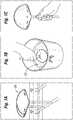
- FIGS 7A and 7Billustrate in magnified cross-section and plan view, respectively, another implant shell 90 of the prior art having texturing formed using conventional cubic salt crystals.
- the shell 90includes an inner wall 92 and an outer textured surface 94.
- This textured surface 94is formed by an embossing process that imprints the texture on uncured silicone material.
- the particular texture illustratedis sold under the tradename Siltex® surface texture by Mentor Corp. of Santa Barbara, CA.
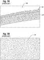
- FIG. 8A and 8Ba magnified cross-section and plan view of an implant shell 100 of the present invention having texturing formed using rounded salt crystals is illustrated.
- the shell 100includes an inner wall 102 and an outer textured surface 104.
- This textured surface 104is formed by applying rounded salt crystals and then dissolving those crystals to leave an open-celled, porous, textured surface, as explained above.
- the textured surface 104is somewhat smoother than those made with angular salt crystals, as seen in Figures 6 and 7 .
- the pores or openings in the open-celled surface 104have smoother dividing walls and fewer angular discontinuities than the pores or openings in conventionally manufactured shells that are otherwise identical but use angular salt crystals rather than rounded salt crystals. As will be shown, this difference surprisingly leads to statistically significant changes in overall shell strength.
- the rounded salt crystalsare applied so as to achieve a depth ranging from a portion of one crystal diameter to a multiple of many crystal diameters.
- the crystalsmay be embedded in the surface of the shell to a depth of from about one to about three times the diameter of the crystals.
- Penetration of the solid crystalsdepends upon the size of the crystals, the thickness of the final uncured layer, the viscosity of the uncured layer and the force with which the crystals are applied. These parameters can be controlled to achieve a desired depth of penetration. For example, if the last layer is relatively thick and low in viscosity, less external force will be required on the solid crystals to produce an acceptable pore depth.
- saltsmay be suitable based on several factors: (1) the salt should be economically available in the desired particle sizes; (2) the salt should be nontoxic in case some remains in the surface of the prosthesis; and (3) the salt should be readily soluble in a solvent that is economically available, nontoxic and does not dissolve the silicone elastomer.
- the rounded salt particlesare sodium chloride crystals which are readily available in granulated form, and can be processed into round crystals, for example, by an industrial milling facility, including Central Salt & Marine Chemicals Research Institute of Bhavnagar, India, a subsidiary of the Council of Scientific & Industrial Research (CSIR), a publicly funded industrial R&D organization in India.
- the solventmay comprise pure water.
- the opening left by the dip molding processmay be patched with unvulcanized sheeting, for example, uncured silicone elastomer sheeting.
- the prosthesisis to be filled with silicone gel, this gel may be added and cured, the filled prosthesis packaged, and the packaged prosthesis sterilized.
- the prosthesisis to be inflated with a saline solution, a one-way valve is assembled and installed, the prosthesis is post cured if required, and the prosthesis is then cleaned, packaged and sterilized.
- a combination breast implant prosthesiscan also be made wherein a gel-filled sac is positioned inside the shell to be surrounded by saline solution.
- an implant shell having a texture formed with round salt crystalsare statistically superior to those formed using cubic salt crystals. This is believed to be due to a reduction in stress concentrations, which may be seen at the sharp corners formed using cubic salt crystals.
- BIOCELL® Saline- or Silicone-Filled Breast Implantsby Allergan, Inc. of Irvine, California. More specifically, random BIOCELL® shells formed using the process described with reference to Figures 6A and 6B were used for comparison. Sixty specimens from this group were cut using an H2 die and tested for tensile strength. Table I below illustrates the results.
- test samples of similar thickness formed by the methods of the present inventionexperience lower stresses during elongation while the break force, ultimate elongation, and tensile strengths are significantly higher.
- the mean thickness of the test samples formed in accordance with present inventionwas 0.054cm (0.0214 inches), while the mean thickness of the prior art test samples was 0.053cm (0.0209 inches), or around a 2.3% difference.
- the mean ultimate break force for samples of the present inventionwas more than 5% greater, the mean ultimate elongation was more than 6% greater, and the mean ultimate tensile strength was nearly 3% greater than samples of the prior art.
- the resulting 662% mean elongation for the sixty shells testedis well past the level required by various regulatory bodies around the word.
- the U.S. standardis 350% from ASTM F703, Standard Specification for Implantable Breast Prostheses.
- the standard for elongationis set at 450% by ISO 14607.
- the implant shells formed by the lost material technique and rounded salt crystalssatisfy these standards with greater margins of confidence than ever before. It is believed that changing from a cubic crystal with sharp corners and edges to the rounded crystals where stress concentrations are more evenly distributed helps statistically meet consensus performance breast standards.
- test samples of similar thickness formed by the methods of the present inventionexperience lower stresses during elongation while the break force, ultimate elongation, and tensile strengths are significantly higher.
- the mean thickness of the test samples formed in accordance with present inventionwas 0.0049cm (0.0196 inches), while the mean thickness of the prior art test samples was 0.5cm (0.0197 inches), or around a 0.05% difference, with the samples made in accordance with the present invention being thinner on average.
Landscapes
- Health & Medical Sciences (AREA)
- Cardiology (AREA)
- Oral & Maxillofacial Surgery (AREA)
- Transplantation (AREA)
- Engineering & Computer Science (AREA)
- Biomedical Technology (AREA)
- Heart & Thoracic Surgery (AREA)
- Vascular Medicine (AREA)
- Life Sciences & Earth Sciences (AREA)
- Animal Behavior & Ethology (AREA)
- General Health & Medical Sciences (AREA)
- Public Health (AREA)
- Veterinary Medicine (AREA)
- Prostheses (AREA)
Description
- The present invention relates to soft prosthetic implants and, more particularly, to methods of texturing the exterior surface of such implants, for instance breast implants, to produce an open-cell texture on the outer surface.
- Implantable prostheses are commonly used to replace or augment body tissue. In the case of breast cancer, it is sometimes necessary to remove some or all of the mammary gland and surrounding tissue, which creates a void that can be filled with an implantable prosthesis. The implant serves to support surrounding tissue and to maintain the appearance of the body. The restoration of the normal appearance of the body has an extremely beneficial psychological effect on post-operative patients, eliminating much of the shock and depression that often follows extensive surgical procedures. Implantable prostheses are also used more generally for restoring the normal appearance of soft tissue in various areas of the body, such as the buttocks, chin, calf, etc.
- Soft implantable prostheses typically include a relatively thin and quite flexible envelope or shell made of vulcanized (cured) silicone elastomer. The shell is filled either with a silicone gel or with a normal saline solution. The filling of the shell takes place before or after the shell is inserted through an incision in the patient.
- The development of implants having textured outer surfaces reflects an attempt to prevent the contraction of the fibrous outer capsule that forms around the implant, which tends to render an implant spherical, painful and aesthetically undesirable. Layers of polyether, polyester or polyurethane foam material have been applied to the back sides of mammary prostheses so that fibrous-tissue could grow into the material and thereby anchor prosthesis securely to the chest wall. However, possible problems exist with foam materials, which may degrade in the body over a period of time, and the effectiveness of these materials for preventing capsular contracture may disappear as they degrade.
- Despite many advances in the construction of soft prosthetic implants, there remains a need for better methods for texturing surfaces of implants.
- The present invention provides processes for forming soft prosthetic implants having textured surfaces and implants formed by said processes. The processes generally comprise the steps of forming a flexible shell, adhering on the exterior of the flexible shell a distribution of rounded particles, curing the flexible shell with the rounded particles adhered thereto, and causing or allowing the rounded particles to be removed from the shell thereby leaving impressions of the particles in the shell to create an open-pored structure on a surface thereof.
- In one embodiment, the flexible shell is formed of a silicone elastomer. For instance, the flexible shell may be formed of a plurality of layers of different silicone elastomers, or the flexible shell may be formed of a single homogeneous layer of a silicone elastomer.
- The step of forming the flexible shell may comprise dipping a mandrel into a liquid dispersion of elastomeric material. Alternatively, the step of forming comprises rotational molding.
- In one embodiment, the step of adhering comprises dipping the flexible shell into a liquid containing the rounded particles, for example, a liquid dispersion or emulsion of rounded particles, for example, rounded salt crystals. Prior to the step of dipping the flexible shell, the process may also include applying a tack coat layer onto the flexible shell.
- In one aspect, the rounded particles comprise rounded crystals of sodium chloride and the solvent is an aqueous composition, for example, water.
- In one embodiment, the rounded particles used in accordance with the invention have a substantially uniform particle size of between about 150 µm (microns) and about 1450 µm (microns). More specifically, the particles have a maximum particle size range selected from a group of ranges consisting of (1) a range between about 180 µm (microns) and about 425 microns, (2) a range between about 425 microns and about 850 µm (microns), and (3) a range between about 850 µm (microns) and about 1450 µm (microns). In one embodiment, about 90% of the particles are in the selected particle size range.
- Another aspect of the invention is a soft prosthetic breast implant, formed by a process comprising the steps of forming a flexible shell of silicone elastomer in the shape of a breast implant, adhering on the exterior of the flexible shell a substantially even distribution of rounded particles, curing the flexible shell with the rounded particles adhered thereto, and exposing the flexible shell to a suitable solvent for a sufficient amount of time to dissolve the rounded particles thereby forming an open-pored structure on the exterior of the flexible shell.
- In one embodiment, at least one, for example, at least two, for example all three of the physical properties of ultimate break force, ultimate elongation, and ultimate tensile strength of an implant formed in accordance with the present process is superior to an implant made using substantially the same process and the same materials except for conventional angular or non-rounded salt crystals instead of rounded salt crystals.
- The step of forming the flexible shell may comprise dipping a mandrel into a liquid dispersion of a shell material, or rotational molding. In one embodiment, the step of forming the flexible shell comprises forming a shell with an opening and the process further includes attaching a patch to cover the opening. The patch may be an unvulcanized elastomer and is attached prior to the step of curing. Alternatively, the step of forming the flexible shell comprises forming a shell with an opening and the process further includes attaching valve, for example, a one-way valve to cover the opening. The rounded salt crystals may comprise sodium chloride.
- A further understanding of the nature and advantages of the present invention are set forth in the following description and claims, particularly when considered in conjunction with the accompanying drawings in which like parts bear like reference numerals.
- Features and advantages of the present invention will become appreciated and the same become better understood with reference to the specification, claims, and appended drawings wherein:
Figures 1A-1C show several steps in a process of dip-forming the shell of a breast implant prosthesis;Figure 2 is a cross-sectional view through one portion of a textured multi-layered breast implant prosthesis shell;Figure 3 is a cross-sectional view through one portion of a textured single-layer breast implant prosthesis shell;Figure 4 is a magnified view of a sample of rounded salt crystals used in the implant texturing process of the present invention;Figure 5 is a magnified view of a sample of cubic salt crystals used in conventional implant texturing processes of the prior art;Figures 6A and 6B are cross-sectional and plan views, respectively, of a textured implant of the prior art;Figures 7A and 7B are cross-sectional and plan views, respectively, of another textured implant of the prior art; andFigures 8A and 8B are cross-sectional and plan views, respectively, of a textured implant in accordance with the present invention.- The present invention provides a saline- or gel-filled soft implant for prostheses and tissue expanders. The implant generally comprises a shell, for example, a silicone elastomer shell, with a textured surface. The primary application for such soft implants is to reconstruct or augment the female breast. Other potential applications are implants for the buttocks, testes, or calf, among other body regions.
Figures 1A-1C illustrate one process for forming flexible implant shells for implantable prostheses and tissue expanders, involving dipping a suitablyshaped mandrel 20 into asilicone elastomer dispersion 22. Many such dispersions are used in the field. Basically they contain a silicone elastomer and a solvent. The silicone elastomer is typically polydimethylsiloxane, polydiphenyl-siloxane or some combination of these two elastomers. Typical solvents include xylene or trichloromethane. Different manufacturers vary the type and amount of the ingredients in the dispersion, the viscosity of the dispersion and the solid content of the dispersion. Nonetheless, the present invention is expected to be adaptable to have utility with a wide variety of silicone rubber dispersions.- The
mandrel 20 is withdrawn from the dispersion and the excess silicone elastomer dispersion is allowed to drain from the mandrel. After the excess dispersion has drained from the mandrel at least a portion of the solvent is allowed to volatilize or evaporate. Normally this is accomplished by flowing air over the coated mandrel at a controlled temperature and humidity. Different manufacturers use various quantities, velocities or directions of air flow and set the temperature and humidity of the air at different values. However, the desired result, driving off the solvent, remains the same. - It is also common for prostheses manufacturers to repeat this dip and volatilize procedure a number of times so that a number of layers are built up on the mandrel to reach a desired shell thickness. A layered structure like most current silicone elastomer shells can be made by sequentially dipping the mandrel in different dispersions. Alternatively, the steps may be repeated in a
single dispersion 22 so that the finished product is a single homogenous material or layer. That is, the dipping process may be done in multiple stages or steps, each step adding more material, yet the finished product exhibits no distinct layers and the entire shell wall is homogenous or uniform in composition. Figure 3 illustrates in cross-section a portion of a textured multi-layered implant of the present invention. A primary barrier to fluid passage through the shell wall is provided by an inner barrier layer 30. Two base coat layers 32, 34 lie radially inward from the barrier layer 30. In some cases a single base coat layer may be used. On the outer side of the barrier layer 30, three further base coat layers 36, 38, 40 are provided, although again a single outer layer may be used. Furthermore, outside of the outer base coat layers 30-40, atack coat layer 42, a layer oftextured crystals 44, and anovercoat layer 48 are provided. The absolute thickness of the implant wall may vary but an exemplary average thickness is about 0.456 mm (0.018 inches). The overall thickness of the textured implant wall is somewhat greater than a similar smooth-walled shell because of the extra layers.- Alternatively,
Figure 3 illustrates a cross-section of textured single-layeredimplant shell wall 50 that is a homogeneous silicone elastomer made entirely of a barrier material that sterically retards permeation of the silicone gel through the shell. Theouter surface 52 of thebarrier layer 50 is textured. The implants made with thesingle layer 50 may be for implant in the breast such that the entire flexible outer shell is shaped accordingly, for instance in with a more flattened posterior side and rounded anterior side. - In addition to the aforementioned dipping process, the flexible shell for the prosthetic implant may be formed using a molding process. For example, a rotational molding process such as described in Schuessler,
U.S. Patent No. 6,602,452 , may be used. The process for forming texturing on the exterior surface is preferably done using a dipping technique, but the formation of the flexible shell may then be accomplished by one of a number of methods. - An exemplary process for forming a textured outer surface on either a multi-layered shell as in
Figure 2 or a single-layered shell as inFigure 3 will now be described. After themandrel 20 ofFigures 1A-1C is raised out of the dispersion with what is to be the final layer adhering thereto, this layer is allowed to stabilize. That is, it is held until the final coating no longer flows freely. This occurs as some of the solvent evaporates from the final coating, raising its viscosity. - Again, it should be understood that alternative methods are contemplated for forming the flexible shell prior to the texturing process. The dip molding process advantageously results in the flexible shell pre-mounted on a dipping mandrel, which can then be used for the texturing process. However, if the flexible shell is made by another technique, such as by rotational molding, it can subsequently be mounted on a dipping mandrel and the process continued in the same manner.
- Once the flexible shell has been stabilized and mounted on the mandrel, any loose fibers or particles are blown off of the exterior of the shell with an anti-static air gun. A tack coat layer is then applied. The tack coat layer may be sprayed on, or may be applied by dipping the flexible shell on the mandrel into a tack coat material, for example, a tack coat dispersion. The operator immerses the flexible shell into the dispersion and returns the mandrel to a rack for stabilization. The time required for stabilization typically varies between about 5 and about 20 minutes. A suitable tack coat layer may be made using the same material employed in the base layers.
- After tack coat layer has been applied, rounded salt particles are applied substantially evenly over the entire surface. The solid particles may be applied manually by sprinkling them over the surface while the mandrel is manipulated, or a machine operating like a bead blaster or sand blaster could be used to deliver a steady stream of solid particles at an adequate velocity to the coating on the mandrel.
- In one embodiment, the coated mandrel is dipped into a body of the particles. In another embodiment, particle application is accomplished by exposing the coated mandrel to a liquid dispersion of the particles. It should be understood that the present invention is not intended to be restricted to any one particular method of applying the particles.
- In one embodiment, a salt bath for coating the tacky flexible shells is prepared by first procuring a quantity of rounded salt crystals and sorting the crystals into a desired size range. For example, unsorted rounded salt crystals are placed in a shaker having a first sieve size (e.g. coarse sieve) and a second sieve size (e.g. fine sieve). Larger salt crystals will be stopped by the coarse sieve at the inlet of the salt shaker, while smaller salt crystals will continue through both of the sieves. Crystals in the desired size range are trapped between the sieves. In a specific embodiment, the first sieve is a 14 mesh sieve and the second sieve is a 20 mesh sieve. In another embodiment, the first sieve is a 20 mesh sieve and the second sieve is a 40 mesh sieve. In yet another embodiment, the first sieve is a 40 mesh sieve and the second sieve is a 80 mesh sieve.
- In one embodiment, the rounded particles used in accordance with the invention have a substantially uniform particle size of between about 150 microns and about 1450 microns.
- In one embodiment, the rounded particles comprise or consist of relatively fine grained particles. For example, in one embodiment, the rounded particles have a maximum particle size of at least about 150 microns, for example, the particles have a maximum particle size in a range of between about 180 microns and about 425 microns. For example, about 90% of the rounded particles will be retained between a sieve having
mesh size 80 and a sieve havingmesh size 40. - In another embodiment, the rounded particles comprise or consist of relatively medium grained particles. For example, in one embodiment, the rounded particles have a maximum particle size of at least about 300 microns, for example, the particles have a maximum particle size in a range of between about 425 microns and about 850 microns. For example, about 90% of the particles will be retained between a sieve having
mesh size 40 and a sieve havingmesh size 20. - In yet another embodiment, the rounded particles comprise or consist of relatively large grained particles. For example, in one embodiment, the rounded particles have a maximum particle size of at least about 800 microns, for example, the particles have a maximum particle size in a range of between about 850 microns and about 1450 microns. For example, about 90% of the particles will be retained between a sieve having
mesh size 20 and a sieve having mesh size 14. - The size of the salt crystals can be selected by sorting a bulk quantity of rounded salt crystals using a series of gradually smaller meshes.
- In accordance with one embodiment of the invention, the salt crystals, for example, those having a particular size distribution are then added to an aqueous salt bath prior to being applied to the shell. The tacky flexible shells are immersed in the salt bath, rotated for even coverage, removed, and then allowed to stabilize. After a suitable period of stabilization, such as between about 5 minutes and about 20 minutes, the flexible shells may be dipped into an overcoat dispersion. A suitable overcoat dispersion may also be made using the same material employed in the base layers. The flexible shells on the mandrels are then mounted on a rack and allowed to volatilize for a sufficient time, such as, for example, about 15 minutes.
- In one embodiment, the entire silicone elastomer shell structure is vulcanized or cured in an oven at elevated temperatures. For example, the temperature of the oven is maintained at a temperature between about 93°C (200°F) and about 176°C (350°F) for a curing time preferably between about 20 minutes and about 1 hour, 40 minutes.
- Upon removal from the oven, the mandrel/shell assembly is placed in a solvent for the solid particles, and the solid particles are allowed to dissolve. The solvent is a material that does not affect the structure or integrity of the silicone elastomer. When the solid particles have dissolved, the assembly is removed from the solvent and the solvent evaporated. The shell is then removed from the mandrel. At this point, it is preferable to place the shell in a solvent for the solid particles and gently agitate it to ensure complete dissolution of all the solid particles. Once the shell has been removed from the solvent, the solvent evaporates or otherwise is removed from the shell.
- Dissolving the solid particles leaves behind open pores, voids or spaces in the surface of the shell. When applied, some of the solid particles are partially exposed so that they can be acted upon by the solvent. These exposed solid particles also provide a way for the solvent to reach those solid particles beneath the surface to dissolve them in turn. The result is an interconnected structure of cells, some of which are open to the surface, in the outer layer of the shell. The process described above produces a shell like that shown in either
Figures 2 or 3 . The shell has a thin outer wall made of silicone elastomer with an opening therein at the point where a support member connected to themandrel 20, which opening will subsequently be covered with a patch. - The present invention diverges from previous processes in the make-up of the salt crystals used in the
dispersion 22. Namely, as seen inFigure 4 ,rounded salt crystals 60 are shown over areference scale 62. In contrast to regularcrystalline sodium chloride 70, as seen against ascale 72 inFigure 5 , the roundedsalt crystals 60 have been appropriately processed to smooth any sharp or non-rounded edges that are typically found on standard sodium chloride crystals 70 (sometimes, termed "cubic salt crystals"). Figures 6A and 6B illustrate in magnified cross-section and plan view, respectively, animplant shell 80 of the prior art having texturing formed using conventional cubic salt crystals. Theshell 80 includes aninner wall 82 and an outertextured surface 84. Thistextured surface 84 is formed by applying cubic salt crystals and then dissolving those crystals to leave an open-celled porous surface. The relativelyrough surface 84 is partly the result of the angular salt crystals used in the formation process. The particular texture illustrated is sold under the tradename Biocell® surface texture by Allergan, Inc. of Irvine, CA.Figures 7A and 7B illustrate in magnified cross-section and plan view, respectively, anotherimplant shell 90 of the prior art having texturing formed using conventional cubic salt crystals. Theshell 90 includes aninner wall 92 and an outertextured surface 94. Thistextured surface 94 is formed by an embossing process that imprints the texture on uncured silicone material. The particular texture illustrated is sold under the tradename Siltex® surface texture by Mentor Corp. of Santa Barbara, CA.- Now with references to
Figures 8A and 8B , a magnified cross-section and plan view of animplant shell 100 of the present invention having texturing formed using rounded salt crystals is illustrated. Theshell 100 includes aninner wall 102 and an outertextured surface 104. Thistextured surface 104 is formed by applying rounded salt crystals and then dissolving those crystals to leave an open-celled, porous, textured surface, as explained above. Thetextured surface 104 is somewhat smoother than those made with angular salt crystals, as seen inFigures 6 and7 . Although not shown in great detail, the pores or openings in the open-celled surface 104 have smoother dividing walls and fewer angular discontinuities than the pores or openings in conventionally manufactured shells that are otherwise identical but use angular salt crystals rather than rounded salt crystals. As will be shown, this difference surprisingly leads to statistically significant changes in overall shell strength. - In one embodiment, the rounded salt crystals are applied so as to achieve a depth ranging from a portion of one crystal diameter to a multiple of many crystal diameters. The crystals may be embedded in the surface of the shell to a depth of from about one to about three times the diameter of the crystals. Penetration of the solid crystals depends upon the size of the crystals, the thickness of the final uncured layer, the viscosity of the uncured layer and the force with which the crystals are applied. These parameters can be controlled to achieve a desired depth of penetration. For example, if the last layer is relatively thick and low in viscosity, less external force will be required on the solid crystals to produce an acceptable pore depth.
- Although standard sodium chloride is preferably used for the rounded salt crystals, other salts may be suitable based on several factors: (1) the salt should be economically available in the desired particle sizes; (2) the salt should be nontoxic in case some remains in the surface of the prosthesis; and (3) the salt should be readily soluble in a solvent that is economically available, nontoxic and does not dissolve the silicone elastomer.
- In one embodiment, the rounded salt particles are sodium chloride crystals which are readily available in granulated form, and can be processed into round crystals, for example, by an industrial milling facility, including Central Salt & Marine Chemicals Research Institute of Bhavnagar, India, a subsidiary of the Council of Scientific & Industrial Research (CSIR), a publicly funded industrial R&D organization in India. When crystalline sodium chloride is used in accordance with the invention, the solvent may comprise pure water. A person of ordinary skill in the art will understand that a number of solid and solvent pairs could be chosen in accordance with various embodiments of the invention.
- After finishing the shell according to the steps described above, additional processing steps may be performed. For example, the opening left by the dip molding process may be patched with unvulcanized sheeting, for example, uncured silicone elastomer sheeting. If the prosthesis is to be filled with silicone gel, this gel may be added and cured, the filled prosthesis packaged, and the packaged prosthesis sterilized. If the prosthesis is to be inflated with a saline solution, a one-way valve is assembled and installed, the prosthesis is post cured if required, and the prosthesis is then cleaned, packaged and sterilized. A combination breast implant prosthesis can also be made wherein a gel-filled sac is positioned inside the shell to be surrounded by saline solution.
- As mentioned above, the properties of an implant shell having a texture formed with round salt crystals are statistically superior to those formed using cubic salt crystals. This is believed to be due to a reduction in stress concentrations, which may be seen at the sharp corners formed using cubic salt crystals.
- To compare the different shells, standard tensile strength specimens were cut from the shells and subjected to stress tests. The comparison shell was a standard commercial textured shell of the prior art sold under the tradename INAMED® BIOCELL® Saline- or Silicone-Filled Breast Implants, by Allergan, Inc. of Irvine, California. More specifically, random BIOCELL® shells formed using the process described with reference to
Figures 6A and 6B were used for comparison. Sixty specimens from this group were cut using an H2 die and tested for tensile strength. Table I below illustrates the results.Table I - Test of Prior Art Commercial Textured Shells Thickness (cm (in)) Stress@ % elongation (bar (psi)) Ultimate Break force (kN (lbf)) Ultimate Elongation (%) Tensile Strength (bar (psi)) 50% 100% 200% 300% Mean 0.0531 (0.0209) 3.64 (52.79) 5.82 (84.40) 12.14 (176.119) 20.38 (295.552) 0.019 (4.272) 621.690 56.467 (819.079) Std. 0.0053 (0.0021) 0.24 (3.54) 0.40 (5.79) 0.83 (11.985) 1.36 (19.723) 0.002 (0.511) 32.227 2.929 (42.482) Min 0.0432 (0.0170) 3.07 (44.49) 4.86 (70.49) 10.18 (147.73) 17.25 (250.188) 0.015 (3.439) 552.016 51.895 (752.760) Max 0.0660 (0.0260) 4.40 (63.89) 7.08 (102.77) 14.74 (213.868) 24.51 (355.503) 0.026 (5.802) 707.647 62.909 (912.512) - Likewise, sixty specimens from a group of shells formed using the process of the present invention were cut using an H2 die and tested for tensile strength. Table II below illustrates the results.
Table II - Test of Shells Produced with Process of the Present Invention Thickness (cm (in)) Stress@ % elongation (bar (psi)) Ultimate Break force (kN (lbf)) Ultimate Elongation (%) Tensile Strength (bar (psi)) 50% 100% 200% 300% Mean 0.0544 (0.0214) 3.27 (47.50) 5.24 (76.08) 11.26 (163.350) 19.37 (280.964) 0.02 (4.494) (662.411) 58.039 (841.880) Std. 0.0033 (0.0013) 0.15 (2.18) 0.26 (3.74) 0.54 (7.811) 0.86 (12.474) 0.001 (0.328) (20.845) 2.330 (33.806) Min 0.0483 (0.0190) 2.93 (42.52) 4.71 (68.33) 10.16 (147.318) 17.44 (252.912) 0.016 (3.617) (591.457) 52.489 (761.376) Max 0.0635 (0.0250) 3.60 (52.20) 5.81 (84.29) 12.36 (179.215) 21.08 (305.826) 0.025 (5.528) (705.347) 64.431 (934.60) - These data show that test samples of similar thickness formed by the methods of the present invention experience lower stresses during elongation while the break force, ultimate elongation, and tensile strengths are significantly higher. Specifically, the mean thickness of the test samples formed in accordance with present invention was 0.054cm (0.0214 inches), while the mean thickness of the prior art test samples was 0.053cm (0.0209 inches), or around a 2.3% difference. However, the mean ultimate break force for samples of the present invention was more than 5% greater, the mean ultimate elongation was more than 6% greater, and the mean ultimate tensile strength was nearly 3% greater than samples of the prior art. Given the number of samples (n = 60), these differences are somewhat surprising given the similar technique for forming the shells and similar thicknesses. Applicants believe that the rounded salt crystals form a smoother open-cell structure on the exterior of the shells which reduces stress concentrations. As such, the test results indicate other than an expected linear relationship proportional to the difference in thickness.
- It is also important to note the improvement in ultimate elongation. The resulting 662% mean elongation for the sixty shells tested is well past the level required by various regulatory bodies around the word. In particular, the U.S. standard is 350% from ASTM F703, Standard Specification for Implantable Breast Prostheses. In Europe and elsewhere, the standard for elongation is set at 450% by ISO 14607. The implant shells formed by the lost material technique and rounded salt crystals satisfy these standards with greater margins of confidence than ever before. It is believed that changing from a cubic crystal with sharp corners and edges to the rounded crystals where stress concentrations are more evenly distributed helps statistically meet consensus performance breast standards.
- In addition, tests were conducted on shells that were formed using the texturing process of the present invention both with conventional cubic salt crystals and with the rounded salt crystals disclosed herein. That is, instead of comparing the shells of the present invention with existing commercial shells, new shells were formed using the same process but with conventional angular or cubic salt crystals.
- Specifically, five shells textured with regular cubic salt crystals were dip molded, and five shells textured with rounded salt crystals were also dip molded. All the shells were subjected to gel curing at 145°C for 8 hours, and then subjected to a simulated sterilization at 127°C for 20.5 hours. Sixty tensile strength specimens from each batch were cut with an H2 die and tested. These results are shown in the following Tables III and IV.
Table III - Test of Textured Shells formed with Cubic Salt Crystals Thickness (cm (in)) Stress@ % elongation (bar (psi)) Ultimate Break force (kN (lbf)) Ultimate Elongation (%) Tensile Strength (bar (psi)) 100% 200% 300% Mean 0.0500 (0.0197) 7.48 (108.44) 16.90 (245.196) 29.48 (427.548) 0.014 (3.157) (574.394) 70.342 (1020.331) Std. 0.0030 (0.0012) 0.30 (4.32) 0.65 (9.455) 1.08 (15.716) 0.001 (0.253) (22.905) 3.475 (50.407) Min 0.0432 (0.017) 6.66 (96.59) 15.07 (218.531) 27.35 (396.776) 0.012 (2.73) (513.924) 62.448 (905.827) Max 0.0559 (0.022) 8.23 (119.34) 18.66 (270.61) 32.50 (471.472) 0.017 (3.781) (616.102) 77.630 (1126.053) Table IV - Test of Textured Shells formed with Rounded Salt Crystals Thickness (cm (in)) Stress@ % elongation (bar (psi)) Ultimate Break force (kN (lbf)) Ultimate Elongation (%) Tensile Strength (bar (psi)) 100% 200% 300% Mean 0.0498 (0.0196) 7.82 (113.49) 17.46 (253.224) 30.14 (437.177) 0.015 (3.321) (593.298) 74.235 (1076.80)7 Std. 0.0038 (0.0015) 0.35 (5.13) 0.73 (10.537) 1.17 (16.966) 0.001 (0.337) (22.248) 3.989 (57.867) Min 0.0381 (0.015) 7.06 (102.42) 16.05 (232.879) 27.65 (401.088) 0.010 (2.189) (543.156) 63.873 (926.505) Max 0.0635 (0.025) 8.58 (124.49) 19.03 (276.015) 32.61 (473.083) 0.019 (4.321) (639.847) 81.431 (1181.189) - Again, these data show that test samples of similar thickness formed by the methods of the present invention experience lower stresses during elongation while the break force, ultimate elongation, and tensile strengths are significantly higher. Specifically, the mean thickness of the test samples formed in accordance with present invention was 0.0049cm (0.0196 inches), while the mean thickness of the prior art test samples was 0.5cm (0.0197 inches), or around a 0.05% difference, with the samples made in accordance with the present invention being thinner on average. However, the mean ultimate break force for samples of the present invention was more than 5% greater, the mean ultimate elongation was more than 3% greater (and sufficient to meet global standards), and the mean ultimate tensile strength was nearly 6% greater than samples of the prior art. Given the number of samples (n = 60) and the fact that the shells were identically formed except for the shape of the salt crystals, these differences are even more surprising than the previous comparison. Once again, the test results indicate a non-linear relationship relative to the difference in thickness.
- Although the invention has been described and illustrated with a certain degree of particularity, it is understood that the present disclosure has been made only by way of example, and that numerous changes in the combination and arrangement of parts can be resorted to by those skilled in the art without departing from the scope of the invention, as hereinafter claimed.
Claims (15)
- A process for forming a soft prosthetic implant, comprising:forming a flexible shell;adhering on the exterior of the flexible shell a substantially even distribution of rounded salt particles;curing the flexible shell with the rounded salt particles adhered thereto; and exposing the flexible shell to a solvent for the rounded salt particles for a sufficient amount of time to dissolve the rounded salt particles and form an open-pored structure on the exterior of the flexible shell, and optionally further comprising the step of applying a tack coat layer to the flexible shell prior to the step of adhering and/or further comprising the step of applying an overcoat to the distribution of rounded salt particles prior to the step of curing.
- The process of claim 1, wherein the rounded salt particles are sodium chloride crystals.
- The process of claim 1, wherein the flexible shell is formed of a silicone elastomer.
- The process of claim 1, wherein the rounded salt particles have a maximum particle size range selected from a group of ranges consisting of (1) a range between about 180 microns and about 425 microns, (2) a range between about 425 µm (microns) and about 850 µm (microns) and (3) a range between about 850 µm (microns) and about (1450 microns), wherein preferably about 90% of the rounded salt particles are in the selected particle size range.
- The process of claim 1, wherein the prosthetic implant is a breast implant and the flexible shell is shaped accordingly.
- The process of claim 1, wherein the step of forming the flexible shell comprises dipping a mandrel into a liquid dispersion of an elastomeric material.
- The process of claim 1, wherein the step of forming the flexible shell comprises rotationally molding the shell.
- The process of claim 1, wherein the step of adhering comprises dipping the flexible shell into a liquid containing the rounded salt particles.
- The process of claim 1, further comprising the step of applying a tack coat layer onto the flexible shell prior to the step of dipping the flexible shell into a liquid containing the rounded salt particles.
- A soft prosthetic breast implant, formed by the process of claim 1 or 8.
- The breast implant of claim 10, wherein the step of forming the flexible shell comprises dipping a mandrel into a liquid dispersion of an elastomeric material.
- The breast implant of claim 11, wherein the step of forming the flexible shell comprises rotationally molding the shell.
- The breast implant of claim 11, wherein the rounded salt particles are sodium chloride crystals.
- The breast implant of claim 11, wherein the rounded salt particles have a maximum particle size range selected from a group of ranges consisting of (1) a range between about 180 µm (microns) and about 425 µm (microns), (2) a range between about 425 µm (microns) and about 850 µm (microns), and (3) a range between about 850 µm (microns) and about 1450 µm (microns).
- The breast implant of claim 14 wherein about 90% of the rounded salt particles are in the selected particle size range.
Priority Applications (1)
| Application Number | Priority Date | Filing Date | Title |
|---|---|---|---|
| EP19163681.0AEP3552581A1 (en) | 2007-11-05 | 2008-10-31 | Soft prosthesis shell texturing method |
Applications Claiming Priority (4)
| Application Number | Priority Date | Filing Date | Title |
|---|---|---|---|
| US98548907P | 2007-11-05 | 2007-11-05 | |
| US99100407P | 2007-11-29 | 2007-11-29 | |
| US12/261,939US8313527B2 (en) | 2007-11-05 | 2008-10-30 | Soft prosthesis shell texturing method |
| PCT/US2008/081940WO2009061672A1 (en) | 2007-11-05 | 2008-10-31 | Soft prosthesis shell texturing method |
Related Child Applications (1)
| Application Number | Title | Priority Date | Filing Date |
|---|---|---|---|
| EP19163681.0ADivisionEP3552581A1 (en) | 2007-11-05 | 2008-10-31 | Soft prosthesis shell texturing method |
Publications (2)
| Publication Number | Publication Date |
|---|---|
| EP2227175A1 EP2227175A1 (en) | 2010-09-15 |
| EP2227175B1true EP2227175B1 (en) | 2019-03-20 |
Family
ID=40588926
Family Applications (2)
| Application Number | Title | Priority Date | Filing Date |
|---|---|---|---|
| EP08847491.1ANot-in-forceEP2227175B1 (en) | 2007-11-05 | 2008-10-31 | Soft prosthesis shell texturing method |
| EP19163681.0AWithdrawnEP3552581A1 (en) | 2007-11-05 | 2008-10-31 | Soft prosthesis shell texturing method |
Family Applications After (1)
| Application Number | Title | Priority Date | Filing Date |
|---|---|---|---|
| EP19163681.0AWithdrawnEP3552581A1 (en) | 2007-11-05 | 2008-10-31 | Soft prosthesis shell texturing method |
Country Status (5)
| Country | Link |
|---|---|
| US (3) | US8313527B2 (en) |
| EP (2) | EP2227175B1 (en) |
| CA (1) | CA2704697C (en) |
| ES (1) | ES2728400T3 (en) |
| WO (1) | WO2009061672A1 (en) |
Cited By (4)
| Publication number | Priority date | Publication date | Assignee | Title |
|---|---|---|---|---|
| US10765501B2 (en) | 2008-08-13 | 2020-09-08 | Allergan, Inc. | Dual plane breast implant |
| US10864661B2 (en) | 2012-12-13 | 2020-12-15 | Allergan, Inc. | Device and method for making a variable surface breast implant |
| US10898607B2 (en) | 2009-03-27 | 2021-01-26 | Allergan, Inc. | Bioerodible matrix for tissue involvement |
| US11202853B2 (en) | 2010-05-11 | 2021-12-21 | Allergan, Inc. | Porogen compositions, methods of making and uses |
Families Citing this family (59)
| Publication number | Priority date | Publication date | Assignee | Title |
|---|---|---|---|---|
| US8313527B2 (en)* | 2007-11-05 | 2012-11-20 | Allergan, Inc. | Soft prosthesis shell texturing method |
| US8506627B2 (en)* | 2008-08-13 | 2013-08-13 | Allergan, Inc. | Soft filled prosthesis shell with discrete fixation surfaces |
| EP2349052A1 (en) | 2008-08-20 | 2011-08-03 | Allergan, Inc. | Self-sealing shell for inflatable prostheses |
| US8632843B2 (en)* | 2008-11-24 | 2014-01-21 | Promimic Ab | Methods and systems of controlled coating of nanoparticles onto micro-rough implant surfaces and associated implants |
| CA2941286C (en)* | 2009-05-13 | 2018-10-16 | Allergan, Inc. | Implants and methods for manufacturing same |
| US8986377B2 (en) | 2009-07-21 | 2015-03-24 | Lifecell Corporation | Graft materials for surgical breast procedures |
| US20110093069A1 (en)* | 2009-10-16 | 2011-04-21 | Allergan, Inc. | Implants and methdos for manufacturing same |
| KR101067475B1 (en)* | 2009-11-19 | 2011-09-27 | 유원석 | Artificial breast implant with silicon open cell foam layer on its surface and method of manufacturing the same |
| FR2952806B1 (en) | 2009-11-20 | 2012-08-10 | Thierry Brinon | IMPLANT FOR ANATOMICAL RECONSTRUCTION OR VOLUMETRIC INCREASE |
| WO2011094155A2 (en)* | 2010-01-28 | 2011-08-04 | Allergan, Inc. | Open celled foams, implants including them and processes for making same |
| US8877822B2 (en) | 2010-09-28 | 2014-11-04 | Allergan, Inc. | Porogen compositions, methods of making and uses |
| US20110196488A1 (en)* | 2010-02-03 | 2011-08-11 | Allergan, Inc. | Degradation resistant implantable materials and methods |
| US9138308B2 (en) | 2010-02-03 | 2015-09-22 | Apollo Endosurgery, Inc. | Mucosal tissue adhesion via textured surface |
| US9072821B2 (en)* | 2010-02-05 | 2015-07-07 | Allergan, Inc. | Biocompatible structures and compositions |
| US9044897B2 (en) | 2010-09-28 | 2015-06-02 | Allergan, Inc. | Porous materials, methods of making and uses |
| US8889751B2 (en) | 2010-09-28 | 2014-11-18 | Allergan, Inc. | Porous materials, methods of making and uses |
| US9138309B2 (en) | 2010-02-05 | 2015-09-22 | Allergan, Inc. | Porous materials, methods of making and uses |
| CA2787458C (en)* | 2010-02-05 | 2017-05-16 | Allergan, Inc. | Inflatable prostheses and methods of making same |
| US9205577B2 (en) | 2010-02-05 | 2015-12-08 | Allergan, Inc. | Porogen compositions, methods of making and uses |
| US8636797B2 (en)* | 2010-02-05 | 2014-01-28 | Allergan, Inc. | Inflatable prostheses and methods of making same |
| CA2797691A1 (en) | 2010-04-27 | 2011-11-03 | Alexei Goraltchouk | Foam-like materials and methods for producing same |
| AU2011252017B2 (en)* | 2010-05-11 | 2015-07-16 | Allergan, Inc. | Porogen compositions, methods of making and uses |
| US20120101574A1 (en)* | 2010-08-20 | 2012-04-26 | Allergan, Inc. | Implantable materials |
| US8679279B2 (en) | 2010-11-16 | 2014-03-25 | Allergan, Inc. | Methods for creating foam-like texture |
| US8546458B2 (en) | 2010-12-07 | 2013-10-01 | Allergan, Inc. | Process for texturing materials |
| KR101288115B1 (en)* | 2011-05-04 | 2013-07-19 | 유원석 | Biodegradable polymer-coated silicon implant material and its manufacturing method |
| US8801782B2 (en) | 2011-12-15 | 2014-08-12 | Allergan, Inc. | Surgical methods for breast reconstruction or augmentation |
| ES2689698T3 (en) | 2012-01-13 | 2018-11-15 | Lifecell Corporation | Breast prostheses and breast prosthesis manufacturing methods |
| US10039633B2 (en) | 2012-06-21 | 2018-08-07 | Lifecell Corporation | Implantable prosthesis having acellular tissue attachments |
| US20140005783A1 (en)* | 2012-06-29 | 2014-01-02 | Allergan, Inc. | Textured prosthesis with reduced capsular contracture response |
| EP2896220B1 (en) | 2012-09-17 | 2016-12-28 | Sonova AG | Cic hearing aid seal and method of manufacturing the same |
| US10820984B2 (en) | 2012-11-14 | 2020-11-03 | ImplantADJUST, LLC | Implant with elastomeric membrane and methods of fabrication thereof |
| US10092392B2 (en) | 2014-05-16 | 2018-10-09 | Allergan, Inc. | Textured breast implant and methods of making same |
| US9539086B2 (en) | 2014-05-16 | 2017-01-10 | Allergan, Inc. | Soft filled prosthesis shell with variable texture |
| JP6438574B2 (en)* | 2014-09-30 | 2018-12-12 | アントニオ・サンブッセティAntonio SAMBUSSETI | Orthotopic artificial endovesical prosthesis |
| BR112017006558A2 (en)* | 2014-09-30 | 2018-04-10 | sambusseti Antonio | orthotopic artificial bladder stent graft |
| US20160130690A1 (en)* | 2014-11-12 | 2016-05-12 | Applied Silicone Corporation | Immersion Curing Process |
| CA2985537A1 (en) | 2015-05-15 | 2016-11-24 | Lifecell Corporation | Tissue matrices for plastic surgery |
| USD752739S1 (en)* | 2015-08-13 | 2016-03-29 | Robert G. Anderson | Tabbed prosthesis insertion bellow |
| CA2996287A1 (en) | 2015-08-21 | 2017-03-02 | Lifecell Corporation | Breast treatment device |
| USD776806S1 (en)* | 2015-10-08 | 2017-01-17 | Robert G. Anderson | Joined universal bellow |
| USD773652S1 (en)* | 2015-10-28 | 2016-12-06 | Robert G. Anderson | Inverted bellow |
| GB201521474D0 (en)* | 2015-12-04 | 2016-01-20 | Univ Manchester | Textured surfaces for implants |
| USD775725S1 (en)* | 2016-05-11 | 2017-01-03 | Robert G. Anderson | Dual chamber prosthesis insertion device |
| US11045307B2 (en)* | 2016-05-11 | 2021-06-29 | Establishment Labs S.A. | Medical implants and methods of preparation thereof |
| AU2017270580B9 (en)* | 2016-05-26 | 2020-01-30 | Allergan, Inc. | Production of rounded salt particles |
| CA3033546A1 (en)* | 2016-08-30 | 2018-03-08 | Allergan, Inc. | Method of manufacturing coated beads |
| US20190201580A1 (en) | 2016-08-31 | 2019-07-04 | Lifecell Corporation | Breast treatment device |
| US10898313B2 (en) | 2018-08-10 | 2021-01-26 | Mentor Worldwide Llc | Systems, devices and methods of making mammary implants and tissue expanders having ribbed shells |
| CR20210170A (en) | 2018-09-10 | 2021-04-30 | Implantadjust Llc | Implant with elastomeric membrane and methods of fabrication thereof |
| USD896383S1 (en) | 2018-09-13 | 2020-09-15 | Allergan, Inc. | Tissue expansion device |
| EP3849458A1 (en) | 2018-09-13 | 2021-07-21 | Allergan, Inc. | Tissue expansion device |
| JP2022507241A (en) | 2018-11-12 | 2022-01-18 | グループ・ピーピーディー・インコーポレイテッド | Porous materials and methods |
| WO2020227095A1 (en) | 2019-05-03 | 2020-11-12 | Lifecell Corporation | Breast treatment device |
| USD931460S1 (en) | 2019-08-01 | 2021-09-21 | Mentor Worldwide Llc | Implant shell having internal, global ribs |
| USD905855S1 (en) | 2019-08-01 | 2020-12-22 | Mentor Worldwide Llc | Implant shell having internal, circumferential ribs |
| USD930834S1 (en)* | 2019-12-10 | 2021-09-14 | David Scott Nutter | Anatomic great toe joint |
| US11471268B2 (en) | 2020-04-25 | 2022-10-18 | Mentor Worldwide Llc | Implants having gel zones with higher levels of cohesiveness for eschewing scalloping, dimpling, and wrinkling |
| NL2027599B1 (en) | 2021-02-19 | 2022-09-19 | Instructure Labs B V | Biocompatible polymeric implant material having a textured surface |
Family Cites Families (274)
| Publication number | Priority date | Publication date | Assignee | Title |
|---|---|---|---|---|
| US2324735A (en) | 1941-01-16 | 1943-07-20 | Abraham N Spanel | Composite rubber article and method of producing same |
| US2805208A (en) | 1952-11-05 | 1957-09-03 | Du Pont | Process for preparing resinous expanded solid |
| US3189921A (en) | 1962-04-11 | 1965-06-22 | William J Pangman | Compound prosthesis |
| US3293663A (en) | 1963-08-12 | 1966-12-27 | Dow Corning | Surgically implantable human breast prosthesis |
| US3378506A (en) | 1963-10-07 | 1968-04-16 | Dayco Corp | Elastomeric porous material and method for manufacturing same |
| US3366975A (en) | 1965-06-04 | 1968-02-06 | William J. Pangman | Compound prosthesis |
| US3559214A (en) | 1968-10-17 | 1971-02-02 | William J Pangman | Compound prosthesis |
| US3600718A (en) | 1969-12-29 | 1971-08-24 | Dow Corning | Inflatable prosthesis |
| US3700380A (en) | 1970-10-01 | 1972-10-24 | Tecna Corp | Surface or lining compatible with blood or other tissue |
| US3665520A (en) | 1970-10-07 | 1972-05-30 | Medical Eng Corp | Surgically implantable breast prosthesis |
| US3852832A (en) | 1972-10-24 | 1974-12-10 | Heyer Schulte Corp | Prosthesis with fixation means |
| US3934274A (en) | 1974-10-29 | 1976-01-27 | Hartley Jr John H | Deflatable mammary augmentation prosthesis |
| US4034751A (en) | 1975-11-24 | 1977-07-12 | International Paper Company | Polymeric sheets as synthetic medical dressings or coverings for wounds |
| DE2738268A1 (en) | 1977-08-25 | 1979-03-08 | Basf Ag | HYDROPHOBIC POLYURETHANE FOAM FOR OIL ABSORPTION |
| US4157085A (en) | 1978-03-24 | 1979-06-05 | Dow Corning Corporation | Surgically implantable tissue expanding device and the method of its use |
| US4264990A (en) | 1979-01-24 | 1981-05-05 | Hamas Robert S | Mammary prosthesis |
| US4433440A (en) | 1979-02-26 | 1984-02-28 | Cohen I Kelman | Prosthesis formed by inner and outer inflatable containers |
| US4231979A (en) | 1979-10-12 | 1980-11-04 | Research Corporation | High surface area permeable material |
| US4298997A (en) | 1979-10-23 | 1981-11-10 | Rybka F James | Device for inhibiting the formation of fibrous capsular contractures in silicone breast implants and method |
| US4650487A (en) | 1980-10-27 | 1987-03-17 | Memorial Hospital For Cancer And Allied Diseases | Multi-lumen high profile mammary implant |
| US4740208A (en) | 1980-11-21 | 1988-04-26 | Cavon Joseph F | Cast gel implantable prosthesis |
| US4470160A (en) | 1980-11-21 | 1984-09-11 | Cavon Joseph F | Cast gel implantable prosthesis |
| US4840628A (en) | 1980-11-21 | 1989-06-20 | Cavon Joseph F | Non-enveloped gel prosthesis |
| US4428082A (en) | 1980-12-08 | 1984-01-31 | Naficy Sadeque S | Breast prosthesis with filling valve |
| US4298998A (en) | 1980-12-08 | 1981-11-10 | Naficy Sadeque S | Breast prosthesis with biologically absorbable outer container |
| US4482577A (en) | 1980-12-16 | 1984-11-13 | Albert Goldstein | Coating process of elastomeric material |
| US4329385A (en) | 1980-12-19 | 1982-05-11 | The United States Of America As Represented By The Administrator Of The National Aeronautics And Space Administration | Texturing polymer surfaces by transfer casting |
| DE3129745C2 (en) | 1981-07-28 | 1985-01-17 | Hoechst Ag, 6230 Frankfurt | Open-pored-microporous shaped body with inherent latent structural convertibility |
| US4773909A (en) | 1981-10-06 | 1988-09-27 | Memorial Hospital For Cancer And Allied Diseases | Multi-lumen high profile mammary implant |
| US4610690A (en) | 1983-02-22 | 1986-09-09 | Mentor Corporation | Rupture resistant prosthesis with bonded surface layer and method of forming same |
| US4643733A (en) | 1983-04-04 | 1987-02-17 | Hilton Becker | Permanent reconstruction implant and method of performing human tissue expansion |
| EP0125400B1 (en) | 1983-04-18 | 1987-07-01 | EBERL, Tertulin | Breast prosthesis |
| US4531244A (en) | 1983-07-14 | 1985-07-30 | Hamas Robert S | Mammary prosthesis with multiple flow spaces |
| US4573999A (en) | 1983-10-14 | 1986-03-04 | Netto Daniel J | Human breast prosthesis |
| US4803025A (en) | 1984-04-23 | 1989-02-07 | Swiss Aluminium Ltd. | Ceramic foam |
| US4772285A (en) | 1984-05-09 | 1988-09-20 | The Board Of Trustees Of The Leland Stanford Junior University | Collagen coated soft tissue prostheses |
| US4963150B1 (en) | 1984-08-30 | 1994-10-04 | Daniel Brauman | Implantable prosthetic device |
| US4648880A (en) | 1984-08-30 | 1987-03-10 | Daniel Brauman | Implantable prosthetic devices |
| US4584324A (en) | 1984-10-26 | 1986-04-22 | Dow Corning Corporation | Silicone foam, water-based, aerosol composition |
| US4944749A (en) | 1985-01-23 | 1990-07-31 | Hilton Becker | Implant and inflating construction |
| US4636213A (en) | 1985-01-24 | 1987-01-13 | Pakiam Anthony I | Implantable prosthesis |
| US4651717A (en) | 1985-04-04 | 1987-03-24 | Dow Corning Corporation | Multiple envelope tissue expander device |
| US4647618A (en) | 1985-05-24 | 1987-03-03 | Dow Corning Corporation | Method of producing a silicone water-based elastomer |
| US4592755A (en) | 1985-06-11 | 1986-06-03 | Ethyl Corporation | Mammary implant |
| US4608396A (en) | 1985-10-16 | 1986-08-26 | Dow Corning Corporation | Method of producing elastomeric silicone foam |
| JPS62231658A (en) | 1985-12-30 | 1987-10-12 | アメリカン・ホスピタル・サプライ・コ−ポレイシヨン | Implantation for breast prosthesis |
| AU593267B2 (en) | 1986-07-22 | 1990-02-08 | Paul O'keeffe | Implantable fabric pouch for mammary prothesis |
| US5002572A (en) | 1986-09-11 | 1991-03-26 | Picha George J | Biological implant with textured surface |
| US5185297A (en) | 1986-09-16 | 1993-02-09 | Lanxide Technology Company, Lp | Ceramic foams |
| US4808558A (en) | 1987-08-26 | 1989-02-28 | Lanxide Technology Company, Lp | Ceramic foams |
| CA1322441C (en) | 1986-11-04 | 1993-09-28 | Joel Quaid | Open-cell, silicone-elastomer medical implant and method for making |
| AU617667B2 (en) | 1986-11-04 | 1991-12-05 | Allergan, Inc. | Open-cell, silicone-elastomer medical implant and method for making |
| US5007929B1 (en) | 1986-11-04 | 1994-08-30 | Medical Products Dev | Open-cell silicone-elastomer medical implant |
| FR2607696B1 (en) | 1986-12-03 | 1995-08-11 | Gosserez Olivier | IMPLANTABLE BREAST PROSTHESIS CONTRARY TO THE FORMATION OF A RETRACTILE SHELL |
| US4773908A (en) | 1986-12-18 | 1988-09-27 | Hilton Becker | Filling tube and seal construction for inflatable implant |
| DE8701925U1 (en) | 1987-02-09 | 1987-07-16 | Anita Spezialmiederfabrik Dr. Helbig GmbH & Co. KG, Kufstein | Breast prosthesis |
| US5022942A (en) | 1987-05-27 | 1991-06-11 | Mentor Corporation | Method of making textured surface prosthesis implants |
| US4960425A (en) | 1987-05-27 | 1990-10-02 | Mentor Corporation | Textured surface frosthesis implants |
| US4859383A (en) | 1987-06-01 | 1989-08-22 | Bio Med Sciences, Inc. | Process of producing a composite macrostructure of organic and inorganic materials |
| US4906423A (en) | 1987-10-23 | 1990-03-06 | Dow Corning Wright | Methods for forming porous-surfaced polymeric bodies |
| US4790848A (en) | 1987-11-27 | 1988-12-13 | Dow Corning Wright | Breast prosthesis with multiple lumens |
| US5035249A (en) | 1987-12-17 | 1991-07-30 | Dow Corning Wright Corporation | Method of making envelope for tissue expander |
| US4841992A (en) | 1987-12-17 | 1989-06-27 | Dow Corning Wright Corporation | Tissue expander and method of making and using |
| US4899764A (en) | 1987-12-17 | 1990-02-13 | Dow Corning Wright | Tissue expander and method of making and using |
| US4955907A (en) | 1987-12-22 | 1990-09-11 | Ledergerber Walter J | Implantable prosthetic device |
| US5282856A (en) | 1987-12-22 | 1994-02-01 | Ledergerber Walter J | Implantable prosthetic device |
| US6228116B1 (en) | 1987-12-22 | 2001-05-08 | Walter J. Ledergerber | Tissue expander |
| US4828560A (en) | 1988-02-17 | 1989-05-09 | Mcgman Medical Corporation | Spring ring tissue expander |
| US4892544A (en) | 1988-03-07 | 1990-01-09 | Dow Corning Wright Corporation | Methods for forming hollow, porous-surfaced elastomeric bodies |
| US4950292A (en) | 1988-04-20 | 1990-08-21 | Dow Corning Corporation | Tissue expanders |
| FR2630637B1 (en) | 1988-04-27 | 1997-09-12 | Muller Guy Henri | NEW ALVEOLAR PROSTHESIS |
| US5011494A (en) | 1988-09-16 | 1991-04-30 | Clemson University | Soft tissue implant with micron-scale surface texture to optimize anchorage |
| US5219361A (en) | 1988-09-16 | 1993-06-15 | Clemson University | Soft tissue implant with micron-scale surface texture to optimize anchorage |
| US4944750A (en) | 1988-10-12 | 1990-07-31 | Cox-Uphoff International Reel | Composite shell material for prosthesis |
| US4859712A (en) | 1988-10-12 | 1989-08-22 | Cox-Uphoff International | Silicone foam and method for making it |
| US5104409A (en) | 1989-01-10 | 1992-04-14 | Baker James L | Mammary implant |
| US5026394A (en) | 1989-01-10 | 1991-06-25 | Baker James L | Mammary implant |
| US5092348A (en) | 1989-01-17 | 1992-03-03 | Mcghan Medical Corporation | Textured tissue expander |
| US4955909A (en) | 1989-01-31 | 1990-09-11 | Bioplasty, Inc. | Textured silicone implant prosthesis |
| WO1990009152A1 (en) | 1989-02-15 | 1990-08-23 | Microtek Medical, Inc. | Biocompatible material and prosthesis |
| US4969899A (en) | 1989-03-08 | 1990-11-13 | Cox-Uphoff International | Inflatable implant |
| US5116387A (en) | 1989-06-09 | 1992-05-26 | American Medical Systems, Inc. | Preparation of injectable polymeric bodies |
| US5007940A (en) | 1989-06-09 | 1991-04-16 | American Medical Systems, Inc. | Injectable polymeric bodies |
| US5158573A (en) | 1989-06-09 | 1992-10-27 | American Medical Systems, Inc. | Injectable polymeric bodies |
| US4965430A (en) | 1989-09-18 | 1990-10-23 | Dow Corning Wright Corp. | Method of laser machining molds with microtextured surfaces |
| US5158571A (en) | 1990-03-09 | 1992-10-27 | Picha George J | Tissue expander and method for expanding tissue |
| US5236453A (en) | 1990-03-09 | 1993-08-17 | Picha George J | Mammary implant and method for reducing capsule contracture |
| US5147398A (en) | 1990-05-04 | 1992-09-15 | Lynn Lawrence A | Multiple compartment breast prosthesis |
| US5092882A (en) | 1990-05-04 | 1992-03-03 | Lynn Lawrence A | Multiple compartment breast prosthesis |
| US5128088A (en) | 1990-08-14 | 1992-07-07 | Hollister Incorporated | Continuous method for making adhesive-lined male external catheters |
| CA2049377A1 (en) | 1990-09-26 | 1992-03-27 | Donald V. Hillegass | Biocompatible body implant having a textured surface |
| US5993716A (en) | 1990-10-19 | 1999-11-30 | Draenert; Klaus | Material and process for its preparation |
| US5034422A (en) | 1990-12-19 | 1991-07-23 | Foamex Lp | Low density, high temperature resistant polymeric bodies |
| US5348788A (en) | 1991-01-30 | 1994-09-20 | Interpore Orthopaedics, Inc. | Mesh sheet with microscopic projections and holes |
| US5354338A (en) | 1991-02-22 | 1994-10-11 | Ledergerber Walter J | Texturized covering for implants |
| US5271736A (en) | 1991-05-13 | 1993-12-21 | Applied Medical Research | Collagen disruptive morphology for implants |
| US5135959A (en) | 1991-05-20 | 1992-08-04 | Sorrento Engineering Corporation | Method of impregnating reticulated foam with polymide foam and products thereof |
| JP2571881B2 (en) | 1991-07-11 | 1997-01-16 | リグナイト株式会社 | Method for producing silicone porous body |
| US5246454A (en) | 1991-07-22 | 1993-09-21 | Peterson Robert L | Encapsulated implant |
| US5171269A (en) | 1991-08-29 | 1992-12-15 | Medical Engineering Corporation | Mammary prosthesis |
| US5146933A (en) | 1991-09-20 | 1992-09-15 | Dow Corning Wright Corporation | Implantable prosthetic device and tethered inflation valve for volume |
| US5681572A (en) | 1991-10-18 | 1997-10-28 | Seare, Jr.; William J. | Porous material product and process |
| US5376117A (en) | 1991-10-25 | 1994-12-27 | Corvita Corporation | Breast prostheses |
| US5236454A (en) | 1991-11-04 | 1993-08-17 | Miller Archibald S | Stacked breast implant |
| US5207709A (en) | 1991-11-13 | 1993-05-04 | Picha George J | Implant with textured surface |
| BR9105626A (en) | 1991-12-27 | 1993-06-29 | Silimed Ltda | PROCESS OF MANUFACTURING IMPLANTS WITH COATED SURFACES |
| US5236457A (en) | 1992-02-27 | 1993-08-17 | Zimmer, Inc. | Method of making an implant having a metallic porous surface |
| US5496370A (en) | 1992-03-13 | 1996-03-05 | Robert S. Hamas | Gel-like prosthetic device |
| US5358521A (en) | 1992-04-01 | 1994-10-25 | Fred Shane | Multiple-layer prosthesis implant with tissue tactility |
| US5534023A (en) | 1992-12-29 | 1996-07-09 | Henley; Julian L. | Fluid filled prosthesis excluding gas-filled beads |
| US5496367A (en) | 1993-01-13 | 1996-03-05 | Fisher; Jack | Breast implant with baffles |
| US5480430A (en) | 1993-06-04 | 1996-01-02 | Mcghan Medical Corporation | Shape-retaining shell for a fluid filled prosthesis |
| US5964803A (en) | 1993-07-27 | 1999-10-12 | Pmt Corporation | Enhanced surface implant and method of manufacture |
| US5525275A (en) | 1993-07-27 | 1996-06-11 | Pmt Corporation | Method of manufacture of enhanced surface implant |
| US5545220A (en) | 1993-11-04 | 1996-08-13 | Lipomatrix Incorporated | Implantable prosthesis with open cell textured surface and method for forming same |
| US5437824A (en) | 1993-12-23 | 1995-08-01 | Moghan Medical Corp. | Method of forming a molded silicone foam implant having open-celled interstices |
| DE69521793T2 (en) | 1994-03-31 | 2002-08-08 | Ernest C. Manders | DIMENSIONALLY ADAPTABLE TISSUE EXTENSION DEVICE |
| FR2721198B1 (en) | 1994-06-16 | 1996-10-31 | Caravel Jean Baudoin | Flexible implantable prosthesis, used in surgery for volume increase or soft tissue reconstruction, in particular breast prosthesis. |
| DE4421516C1 (en) | 1994-06-20 | 1995-07-27 | Helbig Gmbh & Co Orthopaedisch | Replacement breast for women with amputated breast and mfg. process |
| US5630843A (en) | 1994-06-30 | 1997-05-20 | Rosenberg; Paul H. | Double chamber tissue expander |
| US5507808A (en) | 1994-10-26 | 1996-04-16 | Becker; Hilton | Filling tube and seal construction |
| ES2169109T3 (en) | 1994-11-01 | 2002-07-01 | Mentor Corp | TEXTURIZATION PROCEDURE FOR IMPLANTS OF SOFT FABRICS USING A POROUS MANDREL. |
| US5549671A (en) | 1994-12-28 | 1996-08-27 | Mcghan Medical Corporation | Adjunctive filler material for fluid-filled prosthesis |
| US6071309A (en) | 1995-03-22 | 2000-06-06 | Knowlton; Edward W. | Segmental breast expander for use in breast reconstruction |
| US5545217A (en) | 1995-04-20 | 1996-08-13 | C.M. Offray & Son, Inc. | Breast implant |
| US6099565A (en) | 1995-06-07 | 2000-08-08 | Sakura, Jr.; Chester Y. | Prosthetic tissue implant and filler therefor |
| US5630844A (en) | 1995-06-07 | 1997-05-20 | Novamed Medical Products Manufacturing, Inc. | Biocompatible hydrophobic laminate with thermoplastic elastomer layer |
| FR2735354B1 (en) | 1995-06-13 | 1997-08-14 | Perouse Implant Lab | BREAST PROSTHESIS |
| ATE257001T1 (en) | 1995-10-25 | 2004-01-15 | Sm Technologies Llc | METHOD FOR PRODUCING AN OBJECT FROM POROUS MATERIAL |
| EP0791345A1 (en) | 1996-02-23 | 1997-08-27 | Coloplast Corporation | Attachable two-chamber breast prosthesis |
| US6113634A (en) | 1996-04-23 | 2000-09-05 | F + E Gesellschaft fur Bekleidungsinnovation mbH & Co. KG | Breast prosthesis and method for making the same |
| US5824081A (en) | 1996-09-13 | 1998-10-20 | Lipomatrix Incorporated | Hydraulic foam tissue implant |
| US5855588A (en) | 1996-10-03 | 1999-01-05 | General Surgical Innovations, Inc. | Combination dissector and expander |
| US5776159A (en) | 1996-10-03 | 1998-07-07 | General Surgical Innovations, Inc. | Combination dissector and expander |
| US5935164A (en) | 1997-02-25 | 1999-08-10 | Pmt Corporaton | Laminated prosthesis and method of manufacture |
| US6146418A (en) | 1997-02-28 | 2000-11-14 | Berman; Mark | Body implant and method of implanting |
| US7192450B2 (en)* | 2003-05-21 | 2007-03-20 | Dexcom, Inc. | Porous membranes for use with implantable devices |
| BR9806174A (en) | 1997-03-26 | 1999-10-19 | Janssen Pharmaceutica Nv | Pellets having a core coated with an antifungal and a polymer |
| DE69700121T2 (en) | 1997-04-05 | 1999-07-22 | Medisyn Technologies Ltd., Wicklow | Seamless breast prosthesis |
| US5961552A (en) | 1997-08-02 | 1999-10-05 | Pmt Corporation | Internally configured prosthesis |
| US5965076A (en) | 1997-09-22 | 1999-10-12 | The United States Of America As Represented By The Administrator Of The National Aeronautics And Space Administration | Method for fabricating soft tissue implants with microscopic surface roughness |
| WO1999018886A1 (en) | 1997-10-10 | 1999-04-22 | Corbitt John D Jr | Breast implant |
| US6638308B2 (en) | 1997-10-10 | 2003-10-28 | John D. Corbitt, Jr. | Bioabsorbable breast implant |
| EP1047459B1 (en) | 1997-10-21 | 2002-09-18 | augmentec Aktiengesellschaft Implantologie-Epithetik | Implant made of resorbable phosphateglass |
| FR2781142B1 (en) | 1998-07-16 | 2000-10-06 | Perouse Implant Lab | RECONSTRUCTION IMPLANT |
| US6206930B1 (en) | 1998-08-10 | 2001-03-27 | Charlotte-Mecklenburg Hospital Authority | Absorbable tissue expander |
| ATE328618T1 (en) | 1998-10-28 | 2006-06-15 | Cellon S A | STRUCTURED AND POROUS SILICONE RUBBER |
| WO2000033771A2 (en) | 1998-12-11 | 2000-06-15 | Johnson Gerald W | Implants filled with solid or semi-solid material |
| CA2368470C (en) | 1999-03-25 | 2011-05-17 | Metabolix, Inc. | Medical devices and applications of polyhydroxyalkanoate polymers |
| US6214926B1 (en) | 1999-04-01 | 2001-04-10 | Rhodia Inc. | Silicone membranes formed without the use of 1-1-1 trichloroethane |
| JP3400740B2 (en) | 1999-04-13 | 2003-04-28 | 東芝セラミックス株式会社 | Calcium phosphate porous sintered body and method for producing the same |
| US6315796B1 (en) | 1999-05-13 | 2001-11-13 | Board Of Trustees Of The University Of Arkansas | Flexible seamless memory tissue expanding implant |
| FR2794361B1 (en) | 1999-06-02 | 2001-10-19 | Arnaud Rochebiliere | BREAST PROSTHESIS |
| US6183514B1 (en) | 1999-08-16 | 2001-02-06 | Hilton Becker | Self positioning breast prosthesis |
| AU5921300A (en) | 1999-10-22 | 2001-05-08 | Archibald S. Miller | Breast implant |
| US6203570B1 (en) | 1999-11-24 | 2001-03-20 | John L. Baeke | Breast implant with position lock |
| US6692527B1 (en) | 1999-12-01 | 2004-02-17 | Howard T. Bellin | Non-rotating breast implant |
| US6520989B1 (en) | 2000-01-18 | 2003-02-18 | Board Of Trustees Of The University Of Arkansas | Extreme volume flexible integrity prosthesis |
| US6432138B1 (en) | 2000-03-07 | 2002-08-13 | Promatrx, Inc. | Controlled porosity 3-D fabric breast prosthesis |
| US20030105469A1 (en) | 2001-05-09 | 2003-06-05 | Regene Ex Ltd. | Bioresorbable inflatable devices, incision tool and methods for tissue expansion and tissue regeneration |
| US6673285B2 (en) | 2000-05-12 | 2004-01-06 | The Regents Of The University Of Michigan | Reverse fabrication of porous materials |
| US6464726B1 (en) | 2000-07-13 | 2002-10-15 | Jenna Heljenek | Breast implant system and method of augmentation |
| US6531523B1 (en) | 2000-10-10 | 2003-03-11 | Renal Tech International, Llc | Method of making biocompatible polymeric adsorbing material for purification of physiological fluids of organism |
| GB0030635D0 (en) | 2000-12-15 | 2001-01-31 | Aortech Internat Plc | Soft tissue implant |
| CN1359662A (en) | 2000-12-22 | 2002-07-24 | 广州市万和整形材料有限公司 | Artificial mamma with skirt border |
| FR2822383B1 (en) | 2001-03-23 | 2004-12-17 | Perouse Lab | PROSTHESIS FOR PLASTIC RECONSTRUCTION WITH IMPROVED HYDROPHILICITY PROPERTIES, AND METHOD FOR OBTAINING SAME |
| US6605116B2 (en) | 2001-04-03 | 2003-08-12 | Mentor Corporation | Reinforced radius mammary prostheses and soft tissue expanders |
| ES2190339B1 (en) | 2001-05-07 | 2004-11-01 | Ricardo Gonzalez De Vicente | PROTESIS FOR MOM. |
| DE10135275A1 (en) | 2001-07-13 | 2003-01-30 | Jotec Gmbh | Implant and process for its manufacture |
| US6602452B2 (en) | 2001-07-18 | 2003-08-05 | Mcghan Medical Corporation | Rotational molding of medical articles |
| US6702857B2 (en) | 2001-07-27 | 2004-03-09 | Dexcom, Inc. | Membrane for use with implantable devices |
| US6913626B2 (en) | 2001-08-14 | 2005-07-05 | Mcghan Jim J. | Medical implant having bioabsorbable textured surface |
| US20040176493A1 (en) | 2001-08-24 | 2004-09-09 | Ferguson Terrell W. | Silicone foam |
| US6818673B2 (en) | 2001-08-24 | 2004-11-16 | Radiant Holdings, Llc | Method for producing silicone foam utilizing a mechanical foaming agent |
| US6755861B2 (en) | 2001-10-16 | 2004-06-29 | Granit Medical Innovation, Inc. | Device for providing a portion of an organism with a desired shape |
| US7613491B2 (en)* | 2002-05-22 | 2009-11-03 | Dexcom, Inc. | Silicone based membranes for use in implantable glucose sensors |
| US7058439B2 (en) | 2002-05-03 | 2006-06-06 | Contourmed, Inc. | Methods of forming prostheses |
| DE10224352A1 (en) | 2002-06-01 | 2003-12-11 | Mueller Schulte Detlef | Thermosensitive polymer carrier with changeable physical structure for biochemical analysis, diagnostics and therapy |
| FR2840617B1 (en) | 2002-06-10 | 2004-09-10 | Rhodia Chimie Sa | PROCESS FOR PRODUCING POROUS SILICONE MATERIALS |
| AU2002335565A1 (en) | 2002-07-10 | 2004-02-02 | Georgii Marlenovich Sulamanidze | Endoprosthesis for reparative anaplastic surgery. |
| US7767222B2 (en) | 2002-07-31 | 2010-08-03 | Mast Biosurgery Ag | Apparatus and method for preventing adhesions between an implant and surrounding tissues |
| US8048444B2 (en) | 2002-07-31 | 2011-11-01 | Mast Biosurgery Ag | Apparatus and method for preventing adhesions between an implant and surrounding tissues |
| WO2004037318A2 (en) | 2002-10-22 | 2004-05-06 | The Biomerix Corporation | Method and system for intravesicular delivery of therapeutic agents |
| JP2006516193A (en) | 2002-12-06 | 2006-06-29 | アイシス・ファーマシューティカルス・インコーポレーテッド | Rapid identification of pathogens in humans and animals |
| US20050043585A1 (en) | 2003-01-03 | 2005-02-24 | Arindam Datta | Reticulated elastomeric matrices, their manufacture and use in implantable devices |
| US20040143327A1 (en) | 2003-01-17 | 2004-07-22 | Ku David N. | Solid implant |
| US7282241B2 (en) | 2003-04-22 | 2007-10-16 | International Business Machines Corporation | Patterned, high surface area substrate with hydrophilic/hydrophobic contrast, and method of use |
| DE20306637U1 (en) | 2003-04-28 | 2003-06-26 | GfE Medizintechnik GmbH, 90431 Nürnberg | Soft tissue implants such as breast implants, calf muscle prosthesis or the like. |
| US7081135B2 (en) | 2003-06-09 | 2006-07-25 | Lane Fielding Smith | Mastopexy stabilization apparatus and method |
| US6875233B1 (en) | 2003-06-10 | 2005-04-05 | Hinging breast implant | |
| US7632291B2 (en) | 2003-06-13 | 2009-12-15 | Trivascular2, Inc. | Inflatable implant |
| US6802861B1 (en) | 2003-08-26 | 2004-10-12 | Rsh-Gs Trust | Structured breast implant |
| JP5059406B2 (en) | 2003-08-29 | 2012-10-24 | メイヨ フオンデーシヨン フオー メデイカル エジユケーシヨン アンド リサーチ | Hydrogel porogens for the production of biodegradable scaffolds |
| US7169180B2 (en) | 2003-09-03 | 2007-01-30 | Brennan William A | System and method for breast augmentation |
| US7056840B2 (en) | 2003-09-30 | 2006-06-06 | International Business Machines Corp. | Direct photo-patterning of nanoporous organosilicates, and method of use |
| WO2005032418A2 (en) | 2003-10-01 | 2005-04-14 | University Of Washington | Novel porous biomaterials |
| US7309232B2 (en) | 2003-10-10 | 2007-12-18 | Dentigenix Inc. | Methods for treating dental conditions using tissue scaffolds |
| JP4452487B2 (en) | 2003-12-01 | 2010-04-21 | セイコーNpc株式会社 | Class D amplifier |
| EP1786485A4 (en) | 2004-02-06 | 2012-05-30 | Georgia Tech Res Inst | Surface directed cellular attachment |
| US7364592B2 (en) | 2004-02-12 | 2008-04-29 | Dexcom, Inc. | Biointerface membrane with macro-and micro-architecture |
| EP2250974B1 (en)* | 2004-03-03 | 2015-11-25 | Mentor Worldwide LLC | Devices having a textured surface |
| US20070190108A1 (en) | 2004-05-17 | 2007-08-16 | Arindam Datta | High performance reticulated elastomeric matrix preparation, properties, reinforcement, and use in surgical devices, tissue augmentation and/or tissue repair |
| US7674426B2 (en) | 2004-07-02 | 2010-03-09 | Praxis Powder Technology, Inc. | Porous metal articles having a predetermined pore character |
| US7476249B2 (en) | 2004-08-06 | 2009-01-13 | Frank Robert E | Implantable prosthesis for positioning and supporting a breast implant |
| US7758788B2 (en) | 2004-08-13 | 2010-07-20 | Mentor Worldwide Llc | Spray method for forming shells for prostheses |
| US6932840B1 (en) | 2004-09-08 | 2005-08-23 | Absolute Breast Solutions | Implant device |
| US7244270B2 (en) | 2004-09-16 | 2007-07-17 | Evera Medical | Systems and devices for soft tissue augmentation |
| US7641688B2 (en) | 2004-09-16 | 2010-01-05 | Evera Medical, Inc. | Tissue augmentation device |
| US7520896B2 (en) | 2004-10-28 | 2009-04-21 | Fahd Benslimane | Breast implant, use of an associated pouch, and method for determination of a breast implant |
| US7323208B2 (en) | 2004-11-30 | 2008-01-29 | The Regents Of The University Of Michigan | Modified porous materials and method of forming the same |
| GB2421440A (en) | 2004-12-21 | 2006-06-28 | Ishay Wahl | Breast implant with securing means |
| US20060224239A1 (en) | 2005-04-04 | 2006-10-05 | Tiahrt Leif K | Breast implant |
| US7081136B1 (en) | 2005-04-18 | 2006-07-25 | Techno Investments Llc | Adjustable gel filled mammary prosthesis and method |
| TWI382918B (en) | 2005-04-19 | 2013-01-21 | Sulzer Chemtech Ag | Uses of a method for the manufacture of foamed shaped polymer parts of liquid silicone rubber |
| WO2006116392A2 (en) | 2005-04-27 | 2006-11-02 | The Regents Of The University Of Michigan | Particle-containing complex porous materials |
| US20060282164A1 (en) | 2005-06-08 | 2006-12-14 | Joann Seastrom | Implant shell and filler apparatus |
| US7368065B2 (en) | 2005-06-23 | 2008-05-06 | Depuy Products, Inc. | Implants with textured surface and methods for producing the same |
| BRPI0612094A2 (en) | 2005-06-28 | 2010-10-19 | Ami Glicksman | implantable human tissue dilator |
| US8070808B2 (en) | 2005-10-26 | 2011-12-06 | Allergan, Inc. | Variable cohesive gel form-stable breast implant |
| US20070104695A1 (en) | 2005-11-07 | 2007-05-10 | Quijano Rodolfo C | Breast augmentation and reconstruction system |
| US20070104693A1 (en) | 2005-11-07 | 2007-05-10 | Quijano Rodolfo C | Breast augmentation system |
| CN101304813B (en) | 2005-11-11 | 2011-08-17 | 日立化成研究中心公司 | Method of enhancing biocompatibility of elastomeric materials by microtexturing using microdroplet patterning |
| US8257624B2 (en) | 2005-11-14 | 2012-09-04 | Favis Basil D | Porous nanosheath networks, method of making and uses thereof |
| US7547393B2 (en) | 2005-12-07 | 2009-06-16 | General Electric Company | Membrane structure and method of making |
| US7625405B2 (en) | 2006-02-08 | 2009-12-01 | Neosthetic, Llc | Breast implant and method of manufacture |
| FR2900089B1 (en) | 2006-04-21 | 2008-07-25 | Cereplas Soc | PROCESS FOR MANUFACTURING IMPLANTABLE MEDICAL DEVICES WITH TEXTURED SURFACE |
| US8974542B2 (en) | 2006-06-27 | 2015-03-10 | University of Pittsburgh—of the Commonwealth System of Higher Education | Biodegradable elastomeric patch for treating cardiac or cardiovascular conditions |
| JP2008007458A (en) | 2006-06-29 | 2008-01-17 | Freunt Ind Co Ltd | Core particle for layering and manufacturing method thereof |
| US8535719B2 (en) | 2006-07-07 | 2013-09-17 | University Of Pittsburgh - Of The Commonwealth System Of Higher Education | Biohybrid elastomeric scaffolds and methods of use thereof |
| US7867061B2 (en)* | 2006-09-20 | 2011-01-11 | Mentor Worldwide Llc | Texturizing surfaces |
| US7998152B2 (en) | 2006-12-21 | 2011-08-16 | Frank Robert E | Implantable prosthesis for periareolar mastopexy |
| AU2008232682B2 (en) | 2007-03-29 | 2013-03-21 | Medtronic, Inc. | Biodegradable, polymer coverings for breast implants |
| RU2340308C1 (en) | 2007-05-21 | 2008-12-10 | Константин Борисович Кубанцев | Mammary gland implant |
| WO2009110917A1 (en) | 2007-06-07 | 2009-09-11 | Osteotherapeutics, L.L.C. | Bone cement compositions for use as growth factor carriers and methods of making same |
| US7942930B2 (en) | 2007-06-15 | 2011-05-17 | Q-Med Ab | Biocompatible implant system and method |
| WO2009039373A1 (en) | 2007-09-19 | 2009-03-26 | Ethicon, Inc. | Naturally contoured, preformed, three dimensional mesh device for breast implant support |
| US8313527B2 (en) | 2007-11-05 | 2012-11-20 | Allergan, Inc. | Soft prosthesis shell texturing method |
| US8425600B2 (en) | 2007-11-14 | 2013-04-23 | G. Patrick Maxwell | Interfaced medical implant assembly |
| US20110035004A1 (en) | 2007-11-14 | 2011-02-10 | Maxwell G | Interfaced medical implant |
| US20090171049A1 (en) | 2007-12-27 | 2009-07-02 | Linhardt Jeffrey G | Segmented reactive block copolymers |
| US20090198331A1 (en) | 2008-02-01 | 2009-08-06 | Kesten Randy J | Implantable prosthesis with open cell flow regulation |
| US20090198333A1 (en) | 2008-02-05 | 2009-08-06 | Hilton Becker | Method for texturing the surface of a synthetic implant |
| US20090198332A1 (en) | 2008-02-05 | 2009-08-06 | Hilton Becker | Method for texturing the surface of a synthetic implant |
| JP5666448B2 (en) | 2008-08-13 | 2015-02-12 | アラーガン、インコーポレイテッドAllergan,Incorporated | Soft-filled prosthetic shell with a separate fixation surface |
| US8506627B2 (en) | 2008-08-13 | 2013-08-13 | Allergan, Inc. | Soft filled prosthesis shell with discrete fixation surfaces |
| CA2941286C (en) | 2009-05-13 | 2018-10-16 | Allergan, Inc. | Implants and methods for manufacturing same |
| US8197542B2 (en) | 2009-09-02 | 2012-06-12 | Hilton Becker | Self supporting implant in a human body and method for making the same without capsular contracture |
| US20110106249A1 (en) | 2009-09-02 | 2011-05-05 | Hilton Becker | Self supporting and forming breast implant and method for forming and supporting an implant in a human body |
| US8202317B2 (en) | 2009-09-02 | 2012-06-19 | Hilton Becker | Self supporting and forming breast implant and method for forming and supporting an implant in a human body |
| US20110093069A1 (en) | 2009-10-16 | 2011-04-21 | Allergan, Inc. | Implants and methdos for manufacturing same |
| KR101067475B1 (en) | 2009-11-19 | 2011-09-27 | 유원석 | Artificial breast implant with silicon open cell foam layer on its surface and method of manufacturing the same |
| WO2011066441A1 (en) | 2009-11-25 | 2011-06-03 | Healionics Corporation | Implantable medical devices having microporous surface layers and method for reducing foreign body response to the same |
| WO2011094155A2 (en) | 2010-01-28 | 2011-08-04 | Allergan, Inc. | Open celled foams, implants including them and processes for making same |
| US9044897B2 (en) | 2010-09-28 | 2015-06-02 | Allergan, Inc. | Porous materials, methods of making and uses |
| US20110196488A1 (en) | 2010-02-03 | 2011-08-11 | Allergan, Inc. | Degradation resistant implantable materials and methods |
| US20120004722A1 (en) | 2010-02-03 | 2012-01-05 | Allergan, Inc. | Degradation resistant implantable materials and methods |
| US8889751B2 (en) | 2010-09-28 | 2014-11-18 | Allergan, Inc. | Porous materials, methods of making and uses |
| US8877822B2 (en) | 2010-09-28 | 2014-11-04 | Allergan, Inc. | Porogen compositions, methods of making and uses |
| US9072821B2 (en) | 2010-02-05 | 2015-07-07 | Allergan, Inc. | Biocompatible structures and compositions |
| US20110276134A1 (en) | 2010-05-10 | 2011-11-10 | Allergan, Inc. | Silicone implant with imprinted texture |
| US20120041555A1 (en) | 2010-05-10 | 2012-02-16 | Allergan, Inc. | Silicone implant with imprinted texture |
| US9205577B2 (en) | 2010-02-05 | 2015-12-08 | Allergan, Inc. | Porogen compositions, methods of making and uses |
| US9138309B2 (en) | 2010-02-05 | 2015-09-22 | Allergan, Inc. | Porous materials, methods of making and uses |
| CA2797691A1 (en) | 2010-04-27 | 2011-11-03 | Alexei Goraltchouk | Foam-like materials and methods for producing same |
| WO2011143206A2 (en) | 2010-05-10 | 2011-11-17 | Allergan, Inc. | Porous materials, methods of making and uses |
| JP2013528067A (en) | 2010-05-11 | 2013-07-08 | アラーガン、インコーポレイテッド | Porogen materials, manufacturing methods, and uses |
| AU2011252017B2 (en) | 2010-05-11 | 2015-07-16 | Allergan, Inc. | Porogen compositions, methods of making and uses |
| AU2011267923A1 (en) | 2010-06-16 | 2013-01-31 | Allergan, Inc. | Open-cell surface foam materials |
| US20120101574A1 (en) | 2010-08-20 | 2012-04-26 | Allergan, Inc. | Implantable materials |
| US8765039B1 (en) | 2010-10-29 | 2014-07-01 | Walter J. Ledergerber | Implantable micro-textured scar inducing ePTFE structures |
| US8679279B2 (en) | 2010-11-16 | 2014-03-25 | Allergan, Inc. | Methods for creating foam-like texture |
| US8728159B2 (en) | 2010-12-01 | 2014-05-20 | Northwestern University | Prosthetic breast support |
| US8546458B2 (en) | 2010-12-07 | 2013-10-01 | Allergan, Inc. | Process for texturing materials |
| MX2012012801A (en) | 2012-11-01 | 2014-05-27 | Allan Arvizo Huerta | Process for generating mold for stylized breast. |
- 2008
- 2008-10-30USUS12/261,939patent/US8313527B2/enactiveActive
- 2008-10-31EPEP08847491.1Apatent/EP2227175B1/ennot_activeNot-in-force
- 2008-10-31WOPCT/US2008/081940patent/WO2009061672A1/enactiveApplication Filing
- 2008-10-31ESES08847491Tpatent/ES2728400T3/enactiveActive
- 2008-10-31EPEP19163681.0Apatent/EP3552581A1/ennot_activeWithdrawn
- 2008-10-31CACA2704697Apatent/CA2704697C/enactiveActive
- 2011
- 2011-01-21USUS13/010,929patent/US20110117267A1/ennot_activeAbandoned
- 2012
- 2012-10-24USUS13/659,803patent/US9138310B2/enactiveActive
Non-Patent Citations (1)
| Title |
|---|
| None* |
Cited By (4)
| Publication number | Priority date | Publication date | Assignee | Title |
|---|---|---|---|---|
| US10765501B2 (en) | 2008-08-13 | 2020-09-08 | Allergan, Inc. | Dual plane breast implant |
| US10898607B2 (en) | 2009-03-27 | 2021-01-26 | Allergan, Inc. | Bioerodible matrix for tissue involvement |
| US11202853B2 (en) | 2010-05-11 | 2021-12-21 | Allergan, Inc. | Porogen compositions, methods of making and uses |
| US10864661B2 (en) | 2012-12-13 | 2020-12-15 | Allergan, Inc. | Device and method for making a variable surface breast implant |
Also Published As
| Publication number | Publication date |
|---|---|
| US8313527B2 (en) | 2012-11-20 |
| WO2009061672A1 (en) | 2009-05-14 |
| CA2704697C (en) | 2016-03-22 |
| US20130053956A1 (en) | 2013-02-28 |
| US20090118829A1 (en) | 2009-05-07 |
| EP2227175A1 (en) | 2010-09-15 |
| ES2728400T3 (en) | 2019-10-24 |
| CA2704697A1 (en) | 2009-05-14 |
| US9138310B2 (en) | 2015-09-22 |
| EP3552581A1 (en) | 2019-10-16 |
| US20110117267A1 (en) | 2011-05-19 |
Similar Documents
| Publication | Publication Date | Title |
|---|---|---|
| EP2227175B1 (en) | Soft prosthesis shell texturing method | |
| US20240041586A1 (en) | Soft filled prosthesis shell with discrete fixation surfaces | |
| CA2761902C (en) | Implants and methods for manufacturing same | |
| AU2009282389B2 (en) | Soft filled prosthesis shell with discrete fixation surfaces | |
| HK40000075A (en) | Breast implant with an exterior surface comprising different textures | |
| HK1168747B (en) | Implants and methods for manufacturing same | |
| HK1168747A (en) | Implants and methods for manufacturing same | |
| AU2015205876A1 (en) | Soft filled prosthesis shell with discrete fixation surfaces |
Legal Events
| Date | Code | Title | Description |
|---|---|---|---|
| PUAI | Public reference made under article 153(3) epc to a published international application that has entered the european phase | Free format text:ORIGINAL CODE: 0009012 | |
| 17P | Request for examination filed | Effective date:20100526 | |
| AK | Designated contracting states | Kind code of ref document:A1 Designated state(s):AT BE BG CH CY CZ DE DK EE ES FI FR GB GR HR HU IE IS IT LI LT LU LV MC MT NL NO PL PT RO SE SI SK TR | |
| AX | Request for extension of the european patent | Extension state:AL BA MK RS | |
| DAX | Request for extension of the european patent (deleted) | ||
| 17Q | First examination report despatched | Effective date:20130816 | |
| GRAP | Despatch of communication of intention to grant a patent | Free format text:ORIGINAL CODE: EPIDOSNIGR1 | |
| STAA | Information on the status of an ep patent application or granted ep patent | Free format text:STATUS: GRANT OF PATENT IS INTENDED | |
| INTG | Intention to grant announced | Effective date:20180713 | |
| RIN1 | Information on inventor provided before grant (corrected) | Inventor name:POWELL, THOMAS, E. Inventor name:DANG, LOANTRANG | |
| GRAS | Grant fee paid | Free format text:ORIGINAL CODE: EPIDOSNIGR3 | |
| GRAJ | Information related to disapproval of communication of intention to grant by the applicant or resumption of examination proceedings by the epo deleted | Free format text:ORIGINAL CODE: EPIDOSDIGR1 | |
| GRAL | Information related to payment of fee for publishing/printing deleted | Free format text:ORIGINAL CODE: EPIDOSDIGR3 | |
| STAA | Information on the status of an ep patent application or granted ep patent | Free format text:STATUS: EXAMINATION IS IN PROGRESS | |
| INTC | Intention to grant announced (deleted) | ||
| GRAJ | Information related to disapproval of communication of intention to grant by the applicant or resumption of examination proceedings by the epo deleted | Free format text:ORIGINAL CODE: EPIDOSDIGR1 | |
| GRAP | Despatch of communication of intention to grant a patent | Free format text:ORIGINAL CODE: EPIDOSNIGR1 | |
| GRAP | Despatch of communication of intention to grant a patent | Free format text:ORIGINAL CODE: EPIDOSNIGR1 | |
| STAA | Information on the status of an ep patent application or granted ep patent | Free format text:STATUS: GRANT OF PATENT IS INTENDED | |
| INTG | Intention to grant announced | Effective date:20190108 | |
| GRAA | (expected) grant | Free format text:ORIGINAL CODE: 0009210 | |
| STAA | Information on the status of an ep patent application or granted ep patent | Free format text:STATUS: THE PATENT HAS BEEN GRANTED | |
| AK | Designated contracting states | Kind code of ref document:B1 Designated state(s):AT BE BG CH CY CZ DE DK EE ES FI FR GB GR HR HU IE IS IT LI LT LU LV MC MT NL NO PL PT RO SE SI SK TR | |
| REG | Reference to a national code | Ref country code:GB Ref legal event code:FG4D | |
| REG | Reference to a national code | Ref country code:CH Ref legal event code:EP | |
| REG | Reference to a national code | Ref country code:DE Ref legal event code:R096 Ref document number:602008059447 Country of ref document:DE | |
| REG | Reference to a national code | Ref country code:AT Ref legal event code:REF Ref document number:1109716 Country of ref document:AT Kind code of ref document:T Effective date:20190415 | |
| REG | Reference to a national code | Ref country code:IE Ref legal event code:FG4D | |
| REG | Reference to a national code | Ref country code:NL Ref legal event code:MP Effective date:20190320 | |
| PG25 | Lapsed in a contracting state [announced via postgrant information from national office to epo] | Ref country code:FI Free format text:LAPSE BECAUSE OF FAILURE TO SUBMIT A TRANSLATION OF THE DESCRIPTION OR TO PAY THE FEE WITHIN THE PRESCRIBED TIME-LIMIT Effective date:20190320 Ref country code:NO Free format text:LAPSE BECAUSE OF FAILURE TO SUBMIT A TRANSLATION OF THE DESCRIPTION OR TO PAY THE FEE WITHIN THE PRESCRIBED TIME-LIMIT Effective date:20190620 Ref country code:LT Free format text:LAPSE BECAUSE OF FAILURE TO SUBMIT A TRANSLATION OF THE DESCRIPTION OR TO PAY THE FEE WITHIN THE PRESCRIBED TIME-LIMIT Effective date:20190320 Ref country code:SE Free format text:LAPSE BECAUSE OF FAILURE TO SUBMIT A TRANSLATION OF THE DESCRIPTION OR TO PAY THE FEE WITHIN THE PRESCRIBED TIME-LIMIT Effective date:20190320 | |
| REG | Reference to a national code | Ref country code:LT Ref legal event code:MG4D | |
| PG25 | Lapsed in a contracting state [announced via postgrant information from national office to epo] | Ref country code:HR Free format text:LAPSE BECAUSE OF FAILURE TO SUBMIT A TRANSLATION OF THE DESCRIPTION OR TO PAY THE FEE WITHIN THE PRESCRIBED TIME-LIMIT Effective date:20190320 Ref country code:GR Free format text:LAPSE BECAUSE OF FAILURE TO SUBMIT A TRANSLATION OF THE DESCRIPTION OR TO PAY THE FEE WITHIN THE PRESCRIBED TIME-LIMIT Effective date:20190621 Ref country code:LV Free format text:LAPSE BECAUSE OF FAILURE TO SUBMIT A TRANSLATION OF THE DESCRIPTION OR TO PAY THE FEE WITHIN THE PRESCRIBED TIME-LIMIT Effective date:20190320 Ref country code:BG Free format text:LAPSE BECAUSE OF FAILURE TO SUBMIT A TRANSLATION OF THE DESCRIPTION OR TO PAY THE FEE WITHIN THE PRESCRIBED TIME-LIMIT Effective date:20190620 Ref country code:NL Free format text:LAPSE BECAUSE OF FAILURE TO SUBMIT A TRANSLATION OF THE DESCRIPTION OR TO PAY THE FEE WITHIN THE PRESCRIBED TIME-LIMIT Effective date:20190320 | |
| REG | Reference to a national code | Ref country code:AT Ref legal event code:MK05 Ref document number:1109716 Country of ref document:AT Kind code of ref document:T Effective date:20190320 | |
| REG | Reference to a national code | Ref country code:ES Ref legal event code:FG2A Ref document number:2728400 Country of ref document:ES Kind code of ref document:T3 Effective date:20191024 | |
| PG25 | Lapsed in a contracting state [announced via postgrant information from national office to epo] | Ref country code:EE Free format text:LAPSE BECAUSE OF FAILURE TO SUBMIT A TRANSLATION OF THE DESCRIPTION OR TO PAY THE FEE WITHIN THE PRESCRIBED TIME-LIMIT Effective date:20190320 Ref country code:RO Free format text:LAPSE BECAUSE OF FAILURE TO SUBMIT A TRANSLATION OF THE DESCRIPTION OR TO PAY THE FEE WITHIN THE PRESCRIBED TIME-LIMIT Effective date:20190320 Ref country code:CZ Free format text:LAPSE BECAUSE OF FAILURE TO SUBMIT A TRANSLATION OF THE DESCRIPTION OR TO PAY THE FEE WITHIN THE PRESCRIBED TIME-LIMIT Effective date:20190320 Ref country code:SK Free format text:LAPSE BECAUSE OF FAILURE TO SUBMIT A TRANSLATION OF THE DESCRIPTION OR TO PAY THE FEE WITHIN THE PRESCRIBED TIME-LIMIT Effective date:20190320 Ref country code:PT Free format text:LAPSE BECAUSE OF FAILURE TO SUBMIT A TRANSLATION OF THE DESCRIPTION OR TO PAY THE FEE WITHIN THE PRESCRIBED TIME-LIMIT Effective date:20190720 | |
| PG25 | Lapsed in a contracting state [announced via postgrant information from national office to epo] | Ref country code:PL Free format text:LAPSE BECAUSE OF FAILURE TO SUBMIT A TRANSLATION OF THE DESCRIPTION OR TO PAY THE FEE WITHIN THE PRESCRIBED TIME-LIMIT Effective date:20190320 | |
| PG25 | Lapsed in a contracting state [announced via postgrant information from national office to epo] | Ref country code:IS Free format text:LAPSE BECAUSE OF FAILURE TO SUBMIT A TRANSLATION OF THE DESCRIPTION OR TO PAY THE FEE WITHIN THE PRESCRIBED TIME-LIMIT Effective date:20190720 Ref country code:AT Free format text:LAPSE BECAUSE OF FAILURE TO SUBMIT A TRANSLATION OF THE DESCRIPTION OR TO PAY THE FEE WITHIN THE PRESCRIBED TIME-LIMIT Effective date:20190320 | |
| REG | Reference to a national code | Ref country code:DE Ref legal event code:R097 Ref document number:602008059447 Country of ref document:DE | |
| PLBE | No opposition filed within time limit | Free format text:ORIGINAL CODE: 0009261 | |
| STAA | Information on the status of an ep patent application or granted ep patent | Free format text:STATUS: NO OPPOSITION FILED WITHIN TIME LIMIT | |
| PG25 | Lapsed in a contracting state [announced via postgrant information from national office to epo] | Ref country code:DK Free format text:LAPSE BECAUSE OF FAILURE TO SUBMIT A TRANSLATION OF THE DESCRIPTION OR TO PAY THE FEE WITHIN THE PRESCRIBED TIME-LIMIT Effective date:20190320 | |
| 26N | No opposition filed | Effective date:20200102 | |
| PG25 | Lapsed in a contracting state [announced via postgrant information from national office to epo] | Ref country code:SI Free format text:LAPSE BECAUSE OF FAILURE TO SUBMIT A TRANSLATION OF THE DESCRIPTION OR TO PAY THE FEE WITHIN THE PRESCRIBED TIME-LIMIT Effective date:20190320 | |
| PG25 | Lapsed in a contracting state [announced via postgrant information from national office to epo] | Ref country code:TR Free format text:LAPSE BECAUSE OF FAILURE TO SUBMIT A TRANSLATION OF THE DESCRIPTION OR TO PAY THE FEE WITHIN THE PRESCRIBED TIME-LIMIT Effective date:20190320 | |
| PG25 | Lapsed in a contracting state [announced via postgrant information from national office to epo] | Ref country code:MC Free format text:LAPSE BECAUSE OF FAILURE TO SUBMIT A TRANSLATION OF THE DESCRIPTION OR TO PAY THE FEE WITHIN THE PRESCRIBED TIME-LIMIT Effective date:20190320 | |
| REG | Reference to a national code | Ref country code:CH Ref legal event code:PL | |
| PG25 | Lapsed in a contracting state [announced via postgrant information from national office to epo] | Ref country code:LU Free format text:LAPSE BECAUSE OF NON-PAYMENT OF DUE FEES Effective date:20191031 Ref country code:CH Free format text:LAPSE BECAUSE OF NON-PAYMENT OF DUE FEES Effective date:20191031 Ref country code:LI Free format text:LAPSE BECAUSE OF NON-PAYMENT OF DUE FEES Effective date:20191031 | |
| REG | Reference to a national code | Ref country code:BE Ref legal event code:MM Effective date:20191031 | |
| PG25 | Lapsed in a contracting state [announced via postgrant information from national office to epo] | Ref country code:BE Free format text:LAPSE BECAUSE OF NON-PAYMENT OF DUE FEES Effective date:20191031 | |
| PG25 | Lapsed in a contracting state [announced via postgrant information from national office to epo] | Ref country code:IE Free format text:LAPSE BECAUSE OF NON-PAYMENT OF DUE FEES Effective date:20191031 | |
| PG25 | Lapsed in a contracting state [announced via postgrant information from national office to epo] | Ref country code:CY Free format text:LAPSE BECAUSE OF FAILURE TO SUBMIT A TRANSLATION OF THE DESCRIPTION OR TO PAY THE FEE WITHIN THE PRESCRIBED TIME-LIMIT Effective date:20190320 | |
| PG25 | Lapsed in a contracting state [announced via postgrant information from national office to epo] | Ref country code:MT Free format text:LAPSE BECAUSE OF FAILURE TO SUBMIT A TRANSLATION OF THE DESCRIPTION OR TO PAY THE FEE WITHIN THE PRESCRIBED TIME-LIMIT Effective date:20190320 Ref country code:HU Free format text:LAPSE BECAUSE OF FAILURE TO SUBMIT A TRANSLATION OF THE DESCRIPTION OR TO PAY THE FEE WITHIN THE PRESCRIBED TIME-LIMIT; INVALID AB INITIO Effective date:20081031 | |
| PGFP | Annual fee paid to national office [announced via postgrant information from national office to epo] | Ref country code:FR Payment date:20210921 Year of fee payment:14 | |
| PGFP | Annual fee paid to national office [announced via postgrant information from national office to epo] | Ref country code:GB Payment date:20210929 Year of fee payment:14 | |
| PGFP | Annual fee paid to national office [announced via postgrant information from national office to epo] | Ref country code:DE Payment date:20210916 Year of fee payment:14 Ref country code:ES Payment date:20211112 Year of fee payment:14 | |
| PGFP | Annual fee paid to national office [announced via postgrant information from national office to epo] | Ref country code:IT Payment date:20211013 Year of fee payment:14 | |
| REG | Reference to a national code | Ref country code:DE Ref legal event code:R119 Ref document number:602008059447 Country of ref document:DE | |
| GBPC | Gb: european patent ceased through non-payment of renewal fee | Effective date:20221031 | |
| P01 | Opt-out of the competence of the unified patent court (upc) registered | Effective date:20230523 | |
| PG25 | Lapsed in a contracting state [announced via postgrant information from national office to epo] | Ref country code:FR Free format text:LAPSE BECAUSE OF NON-PAYMENT OF DUE FEES Effective date:20221031 Ref country code:DE Free format text:LAPSE BECAUSE OF NON-PAYMENT OF DUE FEES Effective date:20230503 | |
| PG25 | Lapsed in a contracting state [announced via postgrant information from national office to epo] | Ref country code:IT Free format text:LAPSE BECAUSE OF NON-PAYMENT OF DUE FEES Effective date:20221031 Ref country code:GB Free format text:LAPSE BECAUSE OF NON-PAYMENT OF DUE FEES Effective date:20221031 | |
| REG | Reference to a national code | Ref country code:ES Ref legal event code:FD2A Effective date:20231201 | |
| PG25 | Lapsed in a contracting state [announced via postgrant information from national office to epo] | Ref country code:ES Free format text:LAPSE BECAUSE OF NON-PAYMENT OF DUE FEES Effective date:20221101 | |
| PG25 | Lapsed in a contracting state [announced via postgrant information from national office to epo] | Ref country code:ES Free format text:LAPSE BECAUSE OF NON-PAYMENT OF DUE FEES Effective date:20221101 |