EP2227174B1 - Fluid-assisted electrosurgical device - Google Patents
Fluid-assisted electrosurgical deviceDownload PDFInfo
- Publication number
- EP2227174B1 EP2227174B1EP08867090.6AEP08867090AEP2227174B1EP 2227174 B1EP2227174 B1EP 2227174B1EP 08867090 AEP08867090 AEP 08867090AEP 2227174 B1EP2227174 B1EP 2227174B1
- Authority
- EP
- European Patent Office
- Prior art keywords
- fluid
- shaft
- electrode
- tissue
- electrodes
- Prior art date
- Legal status (The legal status is an assumption and is not a legal conclusion. Google has not performed a legal analysis and makes no representation as to the accuracy of the status listed.)
- Active
Links
- 239000012530fluidSubstances0.000titleclaimsdescription144
- 229920000642polymerPolymers0.000claimsdescription21
- 230000000717retained effectEffects0.000claimsdescription6
- 238000005286illuminationMethods0.000claimsdescription4
- 229910052751metalInorganic materials0.000claimsdescription4
- 239000002184metalSubstances0.000claimsdescription4
- 229920001169thermoplasticPolymers0.000claimsdescription4
- 229920001971elastomerPolymers0.000claimsdescription2
- 239000000806elastomerSubstances0.000claimsdescription2
- 210000001519tissueAnatomy0.000description58
- 210000001367arteryAnatomy0.000description14
- 238000000034methodMethods0.000description13
- 239000004020conductorSubstances0.000description12
- 239000000463materialSubstances0.000description12
- 230000008878couplingEffects0.000description9
- 238000010168coupling processMethods0.000description9
- 238000005859coupling reactionMethods0.000description9
- 230000037452primingEffects0.000description9
- 230000004913activationEffects0.000description8
- 239000008280bloodSubstances0.000description8
- 210000004369bloodAnatomy0.000description8
- 238000001356surgical procedureMethods0.000description8
- 210000003462veinAnatomy0.000description8
- 239000007788liquidSubstances0.000description7
- 238000004382pottingMethods0.000description7
- 230000015572biosynthetic processEffects0.000description6
- 230000002572peristaltic effectEffects0.000description6
- 230000000740bleeding effectEffects0.000description5
- 210000004204blood vesselAnatomy0.000description5
- 230000007423decreaseEffects0.000description5
- 238000001746injection mouldingMethods0.000description5
- 239000000779smokeSubstances0.000description5
- 239000007787solidSubstances0.000description5
- FAPWRFPIFSIZLT-UHFFFAOYSA-MSodium chlorideChemical compound[Na+].[Cl-]FAPWRFPIFSIZLT-UHFFFAOYSA-M0.000description4
- 230000008901benefitEffects0.000description4
- 210000000988bone and boneAnatomy0.000description4
- 230000000694effectsEffects0.000description4
- 238000004519manufacturing processMethods0.000description4
- 230000007246mechanismEffects0.000description4
- 239000012528membraneSubstances0.000description4
- 239000002861polymer materialSubstances0.000description4
- 238000007493shaping processMethods0.000description4
- 239000011780sodium chlorideSubstances0.000description4
- 229920002725thermoplastic elastomerPolymers0.000description4
- 238000001816coolingMethods0.000description3
- 239000000835fiberSubstances0.000description3
- 230000023597hemostasisEffects0.000description3
- 230000008569processEffects0.000description3
- 238000000926separation methodMethods0.000description3
- 229910001220stainless steelInorganic materials0.000description3
- 239000010935stainless steelSubstances0.000description3
- 238000009736wettingMethods0.000description3
- 241001269524DuraSpecies0.000description2
- 241000234295MusaSpecies0.000description2
- 235000018290Musa x paradisiacaNutrition0.000description2
- 239000004676acrylonitrile butadiene styreneSubstances0.000description2
- 230000003872anastomosisEffects0.000description2
- 210000000709aortaAnatomy0.000description2
- 238000004891communicationMethods0.000description2
- 238000011109contaminationMethods0.000description2
- 230000008602contractionEffects0.000description2
- 238000010586diagramMethods0.000description2
- 230000005684electric fieldEffects0.000description2
- 230000006870functionEffects0.000description2
- 238000010438heat treatmentMethods0.000description2
- 230000002401inhibitory effectEffects0.000description2
- 238000002347injectionMethods0.000description2
- 239000007924injectionSubstances0.000description2
- 210000003127kneeAnatomy0.000description2
- 238000000465mouldingMethods0.000description2
- 210000003205muscleAnatomy0.000description2
- BASFCYQUMIYNBI-UHFFFAOYSA-NplatinumChemical compound[Pt]BASFCYQUMIYNBI-UHFFFAOYSA-N0.000description2
- 230000004044responseEffects0.000description2
- 239000010963304 stainless steelSubstances0.000description1
- 206010003658Atrial FibrillationDiseases0.000description1
- 102000008186CollagenHuman genes0.000description1
- 108010035532CollagenProteins0.000description1
- 239000004593EpoxySubstances0.000description1
- 229910000589SAE 304 stainless steelInorganic materials0.000description1
- BQCADISMDOOEFD-UHFFFAOYSA-NSilverChemical compound[Ag]BQCADISMDOOEFD-UHFFFAOYSA-N0.000description1
- RTAQQCXQSZGOHL-UHFFFAOYSA-NTitaniumChemical compound[Ti]RTAQQCXQSZGOHL-UHFFFAOYSA-N0.000description1
- 238000002679ablationMethods0.000description1
- 230000003213activating effectEffects0.000description1
- 230000006978adaptationEffects0.000description1
- 239000000853adhesiveSubstances0.000description1
- 230000001070adhesive effectEffects0.000description1
- 238000000137annealingMethods0.000description1
- 238000013459approachMethods0.000description1
- 238000011882arthroplastyMethods0.000description1
- 239000011324beadSubstances0.000description1
- 238000005452bendingMethods0.000description1
- 230000036770blood supplyEffects0.000description1
- 238000009835boilingMethods0.000description1
- 239000002775capsuleSubstances0.000description1
- 230000001112coagulating effectEffects0.000description1
- 239000011248coating agentSubstances0.000description1
- 238000000576coating methodMethods0.000description1
- 229920001436collagenPolymers0.000description1
- 230000006835compressionEffects0.000description1
- 238000007906compressionMethods0.000description1
- 238000010276constructionMethods0.000description1
- 238000011217control strategyMethods0.000description1
- 238000005336crackingMethods0.000description1
- 238000005520cutting processMethods0.000description1
- 230000003247decreasing effectEffects0.000description1
- 239000008367deionised waterSubstances0.000description1
- 229910021641deionized waterInorganic materials0.000description1
- 230000001419dependent effectEffects0.000description1
- 230000000994depressogenic effectEffects0.000description1
- 239000006185dispersionSubstances0.000description1
- 238000010494dissociation reactionMethods0.000description1
- 230000005593dissociationsEffects0.000description1
- 210000001951dura materAnatomy0.000description1
- 238000001125extrusionMethods0.000description1
- 229920005570flexible polymerPolymers0.000description1
- -1for exampleSubstances0.000description1
- 230000004927fusionEffects0.000description1
- 239000007789gasSubstances0.000description1
- PCHJSUWPFVWCPO-UHFFFAOYSA-NgoldChemical compound[Au]PCHJSUWPFVWCPO-UHFFFAOYSA-N0.000description1
- 229910052737goldInorganic materials0.000description1
- 239000010931goldSubstances0.000description1
- 238000009434installationMethods0.000description1
- 238000009413insulationMethods0.000description1
- 230000003601intercostal effectEffects0.000description1
- 238000002357laparoscopic surgeryMethods0.000description1
- 230000003902lesionEffects0.000description1
- 239000004973liquid crystal related substanceSubstances0.000description1
- 230000001050lubricating effectEffects0.000description1
- 210000004705lumbosacral regionAnatomy0.000description1
- 230000013011matingEffects0.000description1
- 238000002324minimally invasive surgeryMethods0.000description1
- 230000004048modificationEffects0.000description1
- 238000012986modificationMethods0.000description1
- 210000005036nerveAnatomy0.000description1
- 230000001537neural effectEffects0.000description1
- 239000012811non-conductive materialSubstances0.000description1
- NJPPVKZQTLUDBO-UHFFFAOYSA-NnovaluronChemical compoundC1=C(Cl)C(OC(F)(F)C(OC(F)(F)F)F)=CC=C1NC(=O)NC(=O)C1=C(F)C=CC=C1FNJPPVKZQTLUDBO-UHFFFAOYSA-N0.000description1
- 230000000399orthopedic effectEffects0.000description1
- 238000010422paintingMethods0.000description1
- 239000004033plasticSubstances0.000description1
- 229920003023plasticPolymers0.000description1
- 229910052697platinumInorganic materials0.000description1
- 239000004417polycarbonateSubstances0.000description1
- 229920000515polycarbonatePolymers0.000description1
- 238000003825pressingMethods0.000description1
- 230000002035prolonged effectEffects0.000description1
- 230000009467reductionEffects0.000description1
- 230000002829reductive effectEffects0.000description1
- 239000000523sampleSubstances0.000description1
- 229910052709silverInorganic materials0.000description1
- 239000004332silverSubstances0.000description1
- 210000004872soft tissueAnatomy0.000description1
- 238000005476solderingMethods0.000description1
- 210000000278spinal cordAnatomy0.000description1
- 238000003860storageMethods0.000description1
- 229920001187thermosetting polymerPolymers0.000description1
- 239000004416thermosoftening plasticSubstances0.000description1
- 210000000115thoracic cavityAnatomy0.000description1
- 229910052719titaniumInorganic materials0.000description1
- 239000010936titaniumSubstances0.000description1
- 238000012546transferMethods0.000description1
- 239000013306transparent fiberSubstances0.000description1
- 238000004148unit processMethods0.000description1
- XLYOFNOQVPJJNP-UHFFFAOYSA-NwaterChemical compoundOXLYOFNOQVPJJNP-UHFFFAOYSA-N0.000description1
- 238000003466weldingMethods0.000description1
Images


Classifications
- A—HUMAN NECESSITIES
- A61—MEDICAL OR VETERINARY SCIENCE; HYGIENE
- A61B—DIAGNOSIS; SURGERY; IDENTIFICATION
- A61B18/00—Surgical instruments, devices or methods for transferring non-mechanical forms of energy to or from the body
- A61B18/04—Surgical instruments, devices or methods for transferring non-mechanical forms of energy to or from the body by heating
- A61B18/12—Surgical instruments, devices or methods for transferring non-mechanical forms of energy to or from the body by heating by passing a current through the tissue to be heated, e.g. high-frequency current
- A61B18/14—Probes or electrodes therefor
- A61B18/1402—Probes for open surgery
- A—HUMAN NECESSITIES
- A61—MEDICAL OR VETERINARY SCIENCE; HYGIENE
- A61B—DIAGNOSIS; SURGERY; IDENTIFICATION
- A61B18/00—Surgical instruments, devices or methods for transferring non-mechanical forms of energy to or from the body
- A61B2018/00053—Mechanical features of the instrument of device
- A61B2018/00107—Coatings on the energy applicator
- A61B2018/00136—Coatings on the energy applicator with polymer
- A—HUMAN NECESSITIES
- A61—MEDICAL OR VETERINARY SCIENCE; HYGIENE
- A61B—DIAGNOSIS; SURGERY; IDENTIFICATION
- A61B18/00—Surgical instruments, devices or methods for transferring non-mechanical forms of energy to or from the body
- A61B18/04—Surgical instruments, devices or methods for transferring non-mechanical forms of energy to or from the body by heating
- A61B18/12—Surgical instruments, devices or methods for transferring non-mechanical forms of energy to or from the body by heating by passing a current through the tissue to be heated, e.g. high-frequency current
- A61B18/1206—Generators therefor
- A61B2018/1246—Generators therefor characterised by the output polarity
- A61B2018/126—Generators therefor characterised by the output polarity bipolar
- A—HUMAN NECESSITIES
- A61—MEDICAL OR VETERINARY SCIENCE; HYGIENE
- A61B—DIAGNOSIS; SURGERY; IDENTIFICATION
- A61B18/00—Surgical instruments, devices or methods for transferring non-mechanical forms of energy to or from the body
- A61B18/04—Surgical instruments, devices or methods for transferring non-mechanical forms of energy to or from the body by heating
- A61B18/12—Surgical instruments, devices or methods for transferring non-mechanical forms of energy to or from the body by heating by passing a current through the tissue to be heated, e.g. high-frequency current
- A61B18/14—Probes or electrodes therefor
- A61B2018/1472—Probes or electrodes therefor for use with liquid electrolyte, e.g. virtual electrodes
- A—HUMAN NECESSITIES
- A61—MEDICAL OR VETERINARY SCIENCE; HYGIENE
- A61B—DIAGNOSIS; SURGERY; IDENTIFICATION
- A61B90/00—Instruments, implements or accessories specially adapted for surgery or diagnosis and not covered by any of the groups A61B1/00 - A61B50/00, e.g. for luxation treatment or for protecting wound edges
- A61B90/30—Devices for illuminating a surgical field, the devices having an interrelation with other surgical devices or with a surgical procedure
- A61B2090/306—Devices for illuminating a surgical field, the devices having an interrelation with other surgical devices or with a surgical procedure using optical fibres
- A—HUMAN NECESSITIES
- A61—MEDICAL OR VETERINARY SCIENCE; HYGIENE
- A61B—DIAGNOSIS; SURGERY; IDENTIFICATION
- A61B90/00—Instruments, implements or accessories specially adapted for surgery or diagnosis and not covered by any of the groups A61B1/00 - A61B50/00, e.g. for luxation treatment or for protecting wound edges
- A61B90/30—Devices for illuminating a surgical field, the devices having an interrelation with other surgical devices or with a surgical procedure
- A61B2090/309—Devices for illuminating a surgical field, the devices having an interrelation with other surgical devices or with a surgical procedure using white LEDs
- A—HUMAN NECESSITIES
- A61—MEDICAL OR VETERINARY SCIENCE; HYGIENE
- A61B—DIAGNOSIS; SURGERY; IDENTIFICATION
- A61B2218/00—Details of surgical instruments, devices or methods for transferring non-mechanical forms of energy to or from the body
- A61B2218/001—Details of surgical instruments, devices or methods for transferring non-mechanical forms of energy to or from the body having means for irrigation and/or aspiration of substances to and/or from the surgical site
- A61B2218/002—Irrigation
Definitions
- This inventionrelates generally to the field of medical devices, systems and methods for use upon a body during surgery. More particularly, the invention relates to electrosurgical devices, systems and methods for use upon tissues of a human body during surgery, particularly open surgery and minimally invasive surgery such as laparoscopic surgery.
- a dry tip electrosurgical devicesuch as a Bovie pencil, can cause the temperature of tissue being treated to rise significantly higher than 100 °C, resulting in tissue desiccation, tissue sticking to the electrodes, tissue perforation, char formation and smoke generation.
- fluid-assisted electrosurgical deviceswhich use saline to inhibit undesirable effects such as tissue desiccation, electrode sticking, smoke production and char formation.
- a fluid-assisted electrosurgical devicewhich provides surgeons greater flexibility in accessing treatment locations during surgical procedures.
- WO 98/27879relates to a bipolar blood coagulator probe that has a coaxial or other bipolar arrangement for use submerged in a sterile fluid during arthroscopy of joints, with an elongated outer electrode positioned in juxtaposition to an elongated inner electrode and with an elongated electrical inner insulation layer positioned between the outer electrode and the inner electrode.
- US 2006/129145relates to an apparatus that is adapted for clamping and coagulating a target tissue while the apparatus is operating in the sub-ablation mode, while the open configuration is adapted for ablating the target tissue via molecular dissociation of tissue components.
- US 2006/041254relates to a hemostat-type device for ablative treatment of tissue, particularly for treatment of atrial fibrillation, that includes a swiveling head assembly and a malleable or articulating handle shaft, as well as, malleable or curved rigid jaws that can permit curved lesion shapes.
- US 2007/043397relates to an instrument including an elongated shaft and a non-conductive handle, wherein the shaft defines a proximal section and a distal section, and the distal section forms an electrically conductive tip, and wherein the shaft is adapted to be transitionable from a straight state to a first bent state.
- This inventionin one embodiment, provides a fluid-assisted bipolar electrosurgical device to treat tissue in a presence of radio frequency energy and a fluid provided from the device.
- the devicecomprises a first electrode and a second electrode at the end of a malleable shaft assembly to be hand shapeable by a user of the device, and at least one fluid outlet.
- the malleable shaft assemblycomprises a first shaft and a second shaft, a length of the first shaft and a length of the second shaft in an outer member comprising a polymer, and at least a portion of the first shaft and at least a portion of the second shaft being malleable.
- the inventionprovides a bipolar electrosurgical device to treat tissue by moving along a tissue surface in a presence of radio frequency energy and a fluid provided simultaneously from the device.
- the devicecomprises a first electrode and a second electrode at the end of a malleable shaft assembly to be hand shapeable by a user of the device, and at least one fluid outlet to provide fluid to the first electrode and at least one fluid outlet to provide fluid to the second electrode.
- the malleable shaft assemblycomprises a first shaft and a second shaft, a length of the first shaft and a length of the second shaft in an outer member comprising a polymer, and at least a portion of the first shaft and at least a portion of the second shaft being malleable.
- the polymermay comprise a thermoplastic polymer, an elastomer, a thermoplastic elastomer or an injection molded polymer.
- the outer memberprovides for a hand shaping of the first shaft and the second shaft simultaneously and with a similar contour.
- At least one of the first shaft and the second shaftcomprises metal, such as stainless steel. In certain embodiments at least a portion of the first shaft is parallel with at least a portion of the second shaft. In other embodiments, at least one of the first electrode and the second electrode is retained at a distal end of the first shaft and the second shaft, respectively.
- At least one of the first electrode and the second electrodeare configured to slide across the tissue surface in the presence of the radio frequency energy and the fluid.
- the first electrode and the second electrodeare of substantially a same size and a same shape and laterally spaced from each other.
- at least one of the first electrode and the second electrodecomprises a surface having a contact angle with the fluid from at least one of the fluid outlets thereon of less than 90 degrees.
- At least one of the first electrode and the second electrodecomprises a domed shape. In other embodiments, at least one of the first electrode and the second electrode comprises a spherical distal end. In certain embodiments, the spherical distal end comprises a hemi-spherical distal end. In other embodiments, the spherical distal end comprises a spherical surface having an arc of about 180 degrees. In certain embodiments, at least one of the first electrode and the second electrode further comprises a cylindrical portion proximal to the spherical distal end.
- At least one fluid outletprovides fluid to the first electrode proximal and/or adjacent to the spherical distal end of the first electrode and at least one fluid outlet provides fluid to the second electrode proximal and/or adjacent to the spherical distal end of the second electrode.
- at least one fluid outletis at least partially defined by at least one of the first electrode and the second electrode.
- at least one fluid outletprovides fluid to a lateral portion of at least one of the first electrode and the second electrode. According to the invention, at least one fluid outlet is located on a lateral portion of the first electrode and the second electrode.
- the devicecomprises a first fluid delivery passage in fluid communication with a fluid outlet to provide fluid to the first electrode and a second fluid delivery passage in fluid communication with a fluid outlet to provide fluid to the second electrode.
- the first fluid delivery passagepasses through a first shaft and the second fluid delivery passage passes through a second shaft.
- the first fluid delivery passagecomprises a lumen a first shaft and the second fluid delivery passage comprises a lumen of a second shaft.
- the devicecomprises a lighting assembly comprising an illuminator which may be configured to direct illumination towards the first electrode and the second electrode.
- the illuminatoris at the end of the malleable shaft assembly.
- the illuminatoris located in a housing at the end of the malleable shaft assembly, and the housing is at least one of translucent and transparent.
- the malleable shaft assemblycomprises a first shaft and a second shaft
- the illuminatormay be between a distal portion of the first shaft and a distal portion of the second shaft or adjacent the distal portion of the first shaft and the distal portion of the second shaft.
- the illuminatormay be adjacent the first electrode and the second electrode.
- the illuminatorcomprises a light source, such as a light emitting diode, or an elongated cylindrical transparent light guide, which may receive light from a light source in a handle of the device and be powered from a power source, such as a battery, also in a handle of the device.
- a light sourcesuch as a light emitting diode
- an elongated cylindrical transparent light guidewhich may receive light from a light source in a handle of the device and be powered from a power source, such as a battery, also in a handle of the device.
- the lighting assemblycomprises at least one wire conductor in the malleable shaft assembly, and the wire conductor in a sheath in an outer member of the malleable shaft assembly which permits movement of the wire conductor therein.
- the inventionprovides devices, systems and methods for controlling tissue temperature at a tissue treatment site during an electrosurgical procedure. This is particularly useful for procedures where it is desirable to shrink, coagulate and seal tissue against blood loss, for example, by shrinking lumens of blood vessels (e.g., arteries, veins).
- blood vesselse.g., arteries, veins.
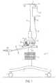
- FIG. 1shows a front view of one embodiment of a system of the present invention having an electrosurgical unit 14 in combination with a fluid source 22 and a handheld electrosurgical device 30.
- FIG. 1shows a movable cart 2 having a chassis 4 which is provided with four wheels 6 for easy transportation.
- the chassis 4carries a support member 8 comprising a hollow cylindrical post to which a storage basket 10 may be fastened and used to store the electrosurgical unit's user manual, as well as additional unused devices.
- the support member 8carries a platform 12 comprising a pedestal table to provide a flat, stable surface for location of the electrosurgical unit 14.
- cart 2further comprises a fluid source carrying pole 16 having a height which may be adjusted by sliding the carrying pole 16 up and down within the support member 8 and thereafter secured in position with a set screw.
- a cross support 18On the top of the fluid source carrying pole 16 is a cross support 18 provided with loops 20 at the ends thereof to provide a hook for carrying fluid source 22.
- fluid source 22comprises a bag of fluid from which the fluid 24 flows through a drip chamber 26 after the bag is penetrated with a spike located at the end of the drip chamber 26. Thereafter, fluid 24 flows through flexible delivery tubing 28 to handheld electrosurgical device 30.
- the fluid delivery tubing 28is made from a polymer material.
- pump 32comprises a peristaltic pump and, more specifically, a rotary peristaltic pump.
- a rotary peristaltic pumpWith a rotary peristaltic pump, a portion of the delivery tubing 28 is loaded into the pump head by raising and lower the pump head in a known manner.
- fluid 24is conveyed within the delivery tubing 28 by waves of contraction placed externally on the tubing 28 which are produced mechanically, typically by rotating pinch rollers 57 which rotate on a drive shaft 55 and intermittently compress the tubing 28 against an anvil support 58.
- pump 32may comprise a linear peristaltic pump.
- fluid 24is conveyed within the delivery tubing 28 by waves of contraction placed externally on the tubing 28 which are produced mechanically, typically by a series of compression fingers or pads which sequentially squeeze the tubing 28 against a support.
- Peristaltic pumpsare generally preferred, as the electro-mechanical force mechanism, here rollers driven by electric motor, does not make contact the fluid 24, thus reducing the likelihood of inadvertent contamination.
- the fluid 24comprises saline, and even more preferably, normal (physiologic) saline.
- salinealine
- other electrically conductive fluidscan be used in accordance with the invention.
- fluid 24may also comprise an electrically non-conductive fluid.
- a non-conductive fluidis less preferred than a conductive fluid, however, the use of a non-conductive fluid still provides certain advantages over the use of a dry electrode including, for example, reduced occurrence of tissue sticking to the electrode of device 30 and cooling of the electrode and/or tissue. Therefore, it is also within the scope of the invention to include the use of a non-conducting fluid, such as, for example, deionized water.
- electrosurgical device 30is connected to electrosurgical unit 14 via a cable 34 which comprises a plurality of electrically insulated wire conductors and at least one plug 36 at the end thereof.
- the electrosurgical unit 14provides radio-frequency (RF) energy via cable 34 to electrosurgical device 30.
- plug receptacle 38 of electrosurgical unit 14receives the plug 36 of device 30 therein to electrically connect device 30 to the electrosurgical unit 14.
- the fluid delivery tubing 28is provided as part of cable 34 and produced with the electrically insulated wires via plastic co-extrusion.
- FIG. 2shows the front panel of the electrosurgical unit 14.
- a power switch 42is used to turn the electrosurgical unit 14 on and off.
- the RF power setting display 44is used to display the RF power setting numerically in watts.
- the power setting displaycomprises a liquid crystal display (LCD). Additionally, this display 44 is used to display errors, in which case the display 44 will show "Err" and blink alternately with a special error code number(s).
- the RF power selectorcomprises RF power setting switches 46a, 46b which are used to select the RF power setting. Pushing the switch 46a increases the RF power setting, while pushing the switch 46b decreases the RF power setting.
- RF power outputmay be set in 5 watt increments in the range of 20 to 100 watts, and 10 watt increments in the range of 100 to 200 watts.
- electrosurgical unit 14includes an RF power activation display comprising an indicator light which illuminates when RF power is activated. Switches 46a, 46b may comprise membrane switches.
- electrosurgical unit 14further includes a fluid flow rate setting display.
- Flow rate setting displaycomprises three indicator lights 50a, 50b and 50c with a first light 50a corresponding to a fluid flow rate setting of low, a second light 50b corresponding to a fluid flow rate setting of medium (intermediate) and a third light 50c corresponding to a flow rate setting of high.
- One of these three indicator lightswill illuminate when a fluid flow rate setting is selected.
- a fluid flow selectorcomprising flow rate setting switches 52a, 52b and 52c are used to select or switch the flow rate setting.
- Three push switchesare provided with the first switch 52a corresponding to a fluid flow rate setting of low, the second switch 52b corresponding to a fluid flow rate setting of medium (intermediate) and the third switch 52c corresponding to a flow rate setting of high. Pushing one of these three switches selects the corresponding flow rate setting of either low, medium (intermediate) or high.
- the medium, or intermediate, flow rate settingis automatically selected as the default setting if no setting is manually selected.
- Switches 52a, 52b and 52cmay comprise membrane switches.
- a priming switch 54is used to initiate priming of device 30 with fluid 24. Pushing switch 54 once initiates operation of pump 32 for a predetermined time period to prime device 30. After the time period is complete, the pump 32 shuts off automatically.
- a priming display 56comprising an indicator light illuminates during the priming cycle.
- the bipolar activation indicator 74illuminates when RF power is activated from the electrosurgical unit 14, either via a handswitch 168 on device 30 or a footswitch.
- a pullout drawer 76is located under the electrosurgical unit 14 where the user of electrosurgical unit 14 may find a short form of the user's manual.
- FIG. 3shows the rear panel of electrosurgical unit 14.
- the rear panel of the electrosurgical unit 14includes a speaker 60 and a volume control knob 62 to adjust the volume of the tone that will sound when the RF power is activated (RF power activation tone).
- the volume of the RF power activation toneis increased by turning the knob clockwise, and decreased by turning the knob counterclockwise. However, the electrosurgical unit 14 prevents this tone from being completely silenced.
- Rear panel of electrosurgical unit 14also includes a power cord receptacle 64 used to connect the main power cord to the electrosurgical unit 14 and an equipotential grounding lug connector 66 used to connect the electrosurgical unit 14 to earth ground using a suitable cable.
- the rear panelalso includes a removable cap 68 for the installation of a bipolar footswitch socket connectable to an internal footswitch circuit of electrosurgical unit 14 so that the RF power may be activated by a footswitch in addition to a handswitch of device 30.
- the rear panelalso includes a fuse drawer 70 which includes which contains two extra fuses, consistent with the line voltage.
- the rear panelincludes a name plate 72 which may provide information such as the model number, serial number, nominal line voltages, frequency, current and fuse rating information of the electrosurgical unit 14.
- the RF power output curve of electrosurgical unit 14is shown in FIG. 4 .
- Impedance Zshown in units of ohms on the X-axis and output power P O is shown in units of watts on the Y-axis.
- the bipolar electrosurgical power (RF)is set to 200 watts.
- the output power P Owill remain constant with the set RF power P S as long as the impedance Z stays between the low impedance cut-off of 30 ohms and the high impedance cut-off of 250 ohms.
- Below an impedance Z of 30 ohmsthe output power P O will decrease as shown by the low impedance ramp. Above an impedance Z of 250 ohms, the output power P O will also decrease as shown by the high impedance ramp.
- Electrosurgical unit 14has also been configured such that the pump speed, and therefore the throughput of fluid expelled by the pump, is predetermined based on two input variables, the RF power setting and the fluid flow rate setting.
- FIG. 5there is shown a relationship of fluid flow rate Q in units of cubic centimetres per minute (cc/min) on the Y-axis, and the RF power setting P S in units of watts on the X-axis.
- the relationshiphas been engineered to inhibit undesirable effects such as tissue desiccation, electrode sticking, smoke production and char formation, while at the same time not providing a fluid flow rate Q at a corresponding RF power setting P S which is so great as to provide too much electrical dispersion and cooling at the electrode/tissue interface.
- electrosurgical unit 14has been configured to increase the fluid flow rate Q linearly with an increasing RF power setting P S for each of three fluid flow rate settings of low, medium and high corresponding to Q L , Q M and Q H , respectively.
- electrosurgical unit 14has been configured to decrease the fluid flow rate Q linearly with an decrease RF power setting P S for each of three fluid flow rate settings of low, medium and high corresponding to Q L , Q M and Q H , respectively.
- FIG. 6shows an exemplary block diagram of how electrosurgical unit 14 processes the inputs of RF power setting P S and the fluid flow rate setting, either Q L , Q M or Q H , to control the pump speed, and therefore the throughput of fluid expelled by the pump 32.
- user selected input values for the RF power setting P S and the fluid flow rate setting of either low, medium and highare entered into electrosurgical unit 14 by pushing corresponding switches for these parameters positioned on the front panel of the electrosurgical unit 14.
- the RF power setting switches 46a, 46b, the flow rate setting switches 52a, 52b, 52c and the priming switch 54are all preferably part of a display panel module 40, preferably comprising a printed circuit board, which receives the inputs into electrosurgical unit 14.
- a main module 43which preferably comprises a printed circuit board including a computer chip 45, a radio-frequency generator 47 and a pump controller 48.
- display panel module 40 and main module 43, as well as other componentsreceive power from a power supply module 49, which also comprises a printed circuit board.
- Computer chip 45preferably comprises a micro-processor unit, a memory, and an input/output control unit.
- the functional relationships between the radio-frequency power level and the flow of the fluidmay be stored in the memory of the computer chip 45. While the functional relationships are preferably stored in the form of the foregoing equations, they may also be stored as numerical data points as part of a database look-up table.
- the input signals 41are received and processed by computer chip 45. More specifically, for example, from the input signal received corresponding to the fluid flow rate setting of either Q L , Q M or Q H , the computer chip 45 may first determine which of the above equations to apply. After determining which equation to apply, computer chip 45 may then apply the relationship to determine the output for flow of the fluid from the pump 32 based on the selected radio-frequency power level. Having determined this output, the computer chip 45 then sends output signals 51 and 53 corresponding to the selected radio-frequency power level and calculated output for flow of the fluid from the pump 32 to the radio-frequency generator 47 and pump controller 48, respectively.
- the pump controller 48controls the speed of the pump drive shaft 55 by controlling the input voltage 59 to the pump motor 61 which rotates the drive shaft 55. More detailed drawings of exemplary electrosurgical unit 14 may be found in U.S. Publication No. 2006/0149225, published July 6, 2006 , which is assigned to the assignee of the present invention.
- Electrosurgical unit 14can include a delay mechanism, such as a timer, to automatically keep the fluid flow on for several seconds after the RF power is deactivated to provide a post-treatment cooling. Electrosurgical unit 14 can also include a delay mechanism, such as a timer, to automatically turn on the fluid flow up to several seconds before the RF power is activated to inhibit the possibility of undesirable effects as tissue desiccation, electrode sticking, char formation and smoke production.
- a delay mechanismsuch as a timer
- Electrosurgical unit 14is particularly configured for use with bipolar devices. With a bipolar device, an alternating current electrical circuit is created between the first and second electrical poles/electrodes of the device.
- An exemplary bipolar electrosurgical device of the present inventionwhich may be used in conjunction with electrosurgical unit 14 of the present invention is shown at reference character 30g in FIG. 7 . While various electrosurgical devices of the present invention are described herein with reference to use with electrosurgical unit, it should be understood that the description of the combination is for purposes of illustrating the system of the invention. Consequently, it should be understood that while the electrosurgical devices disclosed herein may be preferred for use with electrosurgical unit, it may be plausible to use other electrosurgical devices with electrosurgical unit, or it may be plausible to use the electrosurgical devices disclosed herein with another electrosurgical unit.
- exemplary bipolar device 30gcomprises a proximal handle 104 comprising mating handle portions 104a, 104b.
- Handle 104is preferably made of a sterilizable, rigid, non-conductive material, such as a polymer (e.g., polycarbonate).
- handle 104is preferably configured slender, along with the rest of device 30g, to facilitate a user of device 30g to hold and manipulate device 30g like a pen-type device.
- Device 30galso comprises a cable 34 which is connectable to electrosurgical unit 14 and flexible fluid delivery tubing 28 which is connectable to fluid source 22, preferably via a spike located at the end of drip chamber 26, which respectively provide radio frequency energy and fluid to electrodes 114a, 114b.
- cable 34 of device 30gcomprises three insulated wires 34a, 34b, 34c (hidden by platform 171) connectable to electrosurgical unit 14 via three banana (male) plug connectors 37a, 37b, 37c.
- the banana plug connectors 37a, 37b, 37care each assembled with wire conductors 35a, 35b, 35c of insulated wires 34a, 34b, 34c within the housing of plug 36 in a known manner.
- Wire conductors 35a, 35b, 35c of insulated wires 34a, 34b, 34care connected distally to a handswitch assembly 168, and thereafter wire conductors 35a, 35b are connected to semi-circular barrel crimp terminals 39a, 39b which snap connect to a proximal portion of shafts 102a, 102b of shaft assembly 101.
- Handswitch assembly 168comprises a push button 169 which overlies a domed switch 167 on a platform 171 comprising a printed circuit board, with the construction and wiring of the handswitch assembly 168 known in the art.
- domed switch 167forms a closed circuit which is sensed by electrosurgical unit 14, which then provides power to the electrodes 114a, 114b. Additional discussion concerning the handswitch may be found in U.S. Publication No. 2006/0149225, published July 6, 2006 , and U.S. Publication No. 2005/0090816, published April 28, 2005 , which are assigned to the assignee of the present invention.
- Fluid delivery tubing 28 of device 30gis connected within handle 104 to the inlet branch of a Y-splitter 150, which thereafter provides two outlet branches which are connected to the proximal ends of polymer delivery tubing segments 152a, 152b.
- the distal ends of delivery tubing segments 152a, 152bare thereafter connected to the proximal ends of shafts 102a, 102b.
- the lumens 154a, 154bare preferably interference fit over the outside diameter of shafts 102a, 102b to provide an interference fit seal there between.
- a polymer shrink wrap tubing 157a, 157bis then heat shrink wrapped around the connections to better electrically insulate the shafts 102a, 102b and better secure the connections.
- Shaft assembly 101comprises two, preferably parallel, self-supporting, hollow shafts 102a, 102b, which preferably comprise metal such as stainless steel tubing. Retained at and connected to the distal ends of shafts 102a, 102b are two laterally and spatially separated (by empty space) contact elements comprising electrodes 114a, 114b which are configured as mirror images in size and shape, and have a distal end with a surface devoid of edges (to provide a uniform current density) to treat tissue without cutting. Electrodes 114a, 114b preferably comprise an electrically conductive metal. A preferred material is stainless steel. Other suitable materials may include titanium, gold, silver and platinum.
- Electrodes 114a, 114bare preferably configured to slide across the tissue surface in the presence of the radio frequency energy from electrosurgical unit 14 and the fluid 24 from the fluid source 22. As best shown in FIG. 9 , electrodes 114a, 114b have a domed shaped identified by a spherical portion 128a, 128b and a corresponding spherical surface portion 122a, 122b located at the distal end of device 30g which provide a smooth, blunt contour outer surface which is not pointed or sharp.
- the spherical portions 128a, 128b and spherical surface portions 122a, 122bprovide a hemisphere (i.e., less than a full sphere) and hemispherical surface portion having an arc preferably of about 180 degrees.
- the spherical portion 128a, 128b and spherical surface portions 122a, 122bhave a uniform radius in the range between and including about 1.25 mm to about 2.5 mm, and more preferably have a radius of about 1.75 mm.
- electrodes 114a, 114beach preferably comprise a rectilinear cylindrical portion 174a, 174b and a corresponding cylindrical surface portion 176a, 176b located proximal and adjacent to the spherical portion 128a, 128b and spherical surface portion 122a, 122b, respectively.
- cylindrical portions 174a, 174bhave a diameter in the range between and including about 2.5 mm to about 5.0 mm, and more preferably have a diameter of about 3.5 mm.
- cylindrical portions 174a, 174bhave a length in the range between and including about 2 mm to about 6 mm, and more preferably have a length of about 4 mm.
- the longitudinal axes 120a, 120b of electrodes 114a, 114bare separated center-to-center CC about 6.0 mm.
- the actual spatial gap separation GS between electrodes 114a, 114bis about 2.5 mm.
- Each electrode 114a, 114bincludes a longitudinally oriented linear blind bore 115a, 115b and counter bore 117a, 117b.
- the outside diameter of a distal end portion of each shaft 102a, 102bis configured to extend into counter bore 117a, 117b of electrodes 114a, 114b and fit with the diameter of counter bore 117a, 117b, with the distal end 110a, 110b of each shaft 102a, 102b in contact with the bottom of the counter bore.
- the electrodes 114a, 114b and shafts 102a, 102bare then laser welded together.
- the outside diameter of shafts 102a, 102bmay be configured to fit with the diameter of counter bore 117a, 117b to form a press (interference) fit to provide a secure connection.
- electrodes 114a, 114bmay be assembled to shafts 102a, 102b by threaded engagement.
- electrodes 114a, 114bmay be detachably assembled to shafts 102a, 102b such that they may be removed from the shafts 102a, 102b, preferably manually by human hand, so that device 30g may be used with multiple different contact elements/electrodes.
- electrodes 114a, 114balso include a blind bore 119a, 119b, which perpendicularly intersects bore 115a, 115b within cylindrical portion 174a, 174b and provides outlets 185a, 185b for fluid.
- fluid 24 from fluid source 22is communicated through a tubular fluid passage provided by lumen 29 of delivery tubing 28, after which it flows through the tubular fluid passages of Y-splitter 150 and then into the lumens 154a, 154b of delivery tubing segments 152a, 152b to the lumens 103a, 103b of shafts 102a, 102b.
- fluid 24then flows into the tubular passage provided by bore 115a, 115b and then into the tubular passage provided by bore 119a, 119b where it thereafter exits device 30 g from fluid outlets 185a, 185b onto electrodes 114a, 114b.
- fluid outlets 185a, 185bare defined by the cylindrical portions 174a, 174b of electrodes 114a, 114b, and fluid outlets 185a, 185b are proximal and adjacent to the spherical portions 128a, 128b of electrodes 114a, 114b.
- fluid outlets 185a, 185bprovide fluid and are located on lateral portions of electrodes 114a, 114b.
- ⁇is a quantitative measure of the wetting of a solid by a liquid. It is defined geometrically as the angle formed by a liquid at the three phase boundary where a liquid, gas and solid intersect.
- the two electrode/shaft subassembliesare then preferably assembled to nosepiece 107, with the proximal ends of each shaft 102a, 102b inserted into the distal end of shaft aperture 123a, 123b of nosepiece 107.
- Each electrode/shaft subassemblyis extended through shaft aperture 123a, 123b until the proximal end of each electrode 114a, 114b makes interference contact with the distal end of nosepiece 107.
- nosepiece 107provides a housing, particularly for a light assembly discussed below, and holds the electrodes 114a, 114b stationary at the designed separation distance and proper orientation.
- Nosepiece 107preferably comprises a rigid polymer material, and more preferably comprises acrylonitrile-butadiene-styrene (ABS).
- shafts 102a, 102bare retained in position relative to each other upon being assembled in C-shaped portion 113a, 113b of an aperture 113 of one or more retaining clips 109.
- Retaining clips 109are assembled to shafts 102a, 102b after the electrode/shaft subassemblies are inserted and seated relative to nosepiece 107. As best shown in FIG.
- the clips 109may be configured to slide along the length of the shafts 102a, 102b as to adjust or vary the location of the clips 109 on the shafts 102a, 102b. Once the clips 109 are properly positioned, they may then be held in fixed position relative to shafts 102a, 102b by the use of an adhesive.
- the retaining clips 109preferably comprise a polymer material, and more preferably comprise acrylonitrile-butadiene-styrene (ABS).
- device 30galso preferably includes a lighting assembly comprising an illuminator 131 (shown in FIG. 7 ), which comprises a light source configured to direct illumination towards the electrodes 114a, 114b.
- illuminator 131preferably comprises a light emitting diode (LED) 133.
- LED 133includes a lens 135 having a spherical distal end and terminals 137a, 137b.
- LED 133is preferably located between and adjacent a distal portion of shafts 102a, 102b and slightly proximally adjacent to the electrodes 114a, 114b (about 3.175 mm (0.125 inches) to 50.8 mm (2 inches), and more preferably about 6.35 mm (0.25 inches) to 25.4 mm (1 inch), and even more preferably about 9.525 mm (0.375 inches) to provide bright illumination primarily between the electrodes 114a, 114b, while at the same time minimizing the shadows caused by the electrodes 114a, 114b and the likelihood of blood contamination during use.
- nosepiece 107may also be made translucent or transparent to further reduce shadows.
- lens 135preferably emits white light and has a half intensity angle of about 15 to 20 degrees.
- terminals 137a, 137bare connected, preferably by resistance welding, to the distal ends of wire conductors 139a, 139b of insulated wires 141a, 141b.
- the proximal ends of wire conductors 139a, 139bare connected, preferably by soldering, to a printed circuit board 143 of an activation assembly 145. As best shown in FIG.
- activation assembly 145includes a power source 147 preferably comprising a plurality of batteries provided in series relationship which provide power to LED 133 in response to the formation of a closed circuit with wire conductors 139a, 139b when switch 149 is in a depressed position in response to the pressing of button 151 (shown in FIG. 8 ).
- the light sourceoperates independent of the power of the electrosurgical unit 14 and may also be activated simultaneously with the RF power from electrosurgical unit 14.
- LED terminals 137a, 137bare connected to wire conductors 139a, 139b of insulated wires 141a, 141b
- insulated wires 141a, 141bare then passed through the lumen 155 of a hollow polymer tubing 153 which provides a sheath.
- LED 133, insulated wires 141a, 141b and the polymer tubing 153are then loaded into a portion of aperture 113 of retaining clips 111 between shafts 102a, 102b.
- the insulated wires 141a, 141b within the polymer tubing 153are retained in position between shafts 102a, 102b.
- LED 133is inserted into the LED aperture 125 of nosepiece 107 which is located between the apertures 123a, 123b for shafts 102a, 102b.
- Potting material 129preferably comprises a polymer material, and more preferably comprises an ultraviolet cured thermoset epoxy.
- outer member 147electrically insulates the exposed length of shafts 102a, 102b between potting material 129 and handle 104. Furthermore, similar to clips 111, outer member 147 retains shafts 102a, 102b and polymer tube 153 in position relative to each other.
- Outer member 147is preferably formed by injection molding.
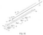
- the sub-assembly shown in FIG. 11comprising electrodes 114a, 114b; shafts 102a, 102b; nosepiece 107; retaining clips 109; LED 133; insulated wires 141a, 141b; polymer tubing 153; and potting material 129 is placed in the injection mold prior to the introduction of polymer.
- the moldis closed and preferably thermoplastic polymer, and more preferably a thermoplastic elastomer, is injected into the unoccupied portions of the mold cavity to overmold and mold-in place portions of the sub-assembly as shown in FIG. 12 .
- the thermoplastic elastomerhas a Shore A durometer of 90-95 and comprises a thermoplastic rubber.
- retainer clips 111provide the benefit of retaining shafts 102a, 102b and polymer tube 153 in position relative to each other. Furthermore, during the injection molding process, retainer clips 111 provide the added benefit of locating the shafts 102a, 102b and polymer tube 153 in the middle of the mold cavity away from the surface of the mold to better ensure that the shafts 102a, 102b and polymer tube 153 are centrally located within the polymer molding.
- potting material 129in addition to retaining shafts 102a, 102b and LED 133 relative to nosepiece 107 prior to injection molding, provides the added benefit of inhibiting the injected thermoplastic from entering shaft apertures 123a, 123b and LED aperture 125 of nosepiece 107.
- the potting material 129, as well as the nosepiece 107may be eliminated.
- shafts 102a, 102b of device 30gare preferably malleable to provide a malleable shaft assembly 101.
- a distal portion of shafts 102a, 102bmay be bendable at an angle relative to the longitudinal axis of the proximal portion of shafts 102a, 102b during manufacturing of device 30g so they may be provided to users of device 30g at various angles.
- anglemay range from about 5 degrees to 90 degrees, and more preferably, about 15 degrees to 45 degrees, and even more preferably about 30 degrees.
- malleablemeans able to be shaped, particularly by bending (without a mechanical mechanism, such as a hinge or joint).
- Outer member 147in addition to electrically insulating shafts 102a, 102b from one another, has been found to be particularly useful in facilitating the hand shaping of shafts 102a, 102b of shaft assembly 101 simultaneously and with a similar contour without cracking. In this manner surgeons and other users of device 30g need not bend the shafts 102a, 102b individually. Also, hollow tube 153, by providing a sheath for wires 141a, 141b in outer member 147 which permits movement of the wires 141a, 141b, also facilitates the hand shaping of shaft assembly 101.
- Hollow tube 153prevents outer member 147 from molding directly to insulated wires 141a, 141b, which could caused conductors 139a, 139b to break during the shaping of shaft assembly 101 if not permitted to move independently and freely within the lumen 155 of tubing 153.
- shafts 102a, 102bpreferably have an outer wall diameter of about 1.6 mm (0.063 inches) and an inner wall diameter of about 0.081 mm (0.032 inches).
- Shafts 102a, 102balso preferably are made from 304 stainless steel with a temper from about 1 ⁇ 2 to 3 ⁇ 4 hard (896.32 MPa to 1034.21 MPa (130,000 to 150,000 psi.) (pounds per square inch) tensile strength) and an elongation at break of about 40%.
- Shafts 102a, 102b with the foregoing propertiesprovide sufficient stiffness as not to be too pliable during normal use of device 30g, while at the same time inhibiting the shafts 102a, 102b from kinking or breaking when shaped for application.
- shafts 102a, 102bmay kink, and when the wall thickness is too thick, the shafts 102a, 102b may be too stiff.
- a shaft 102a, 102b with a larger diametermay also kink more than a shaft of smaller diameter.
- Shafts 102a, 102bmay also be malleable for a portion of the length or full length depending on application.
- the shafts 102a, 102bcan be made with variable stiffness along the length and be malleable only for a distal portion thereof. Preferably this is performed by controlled annealing of the shafts 102a, 102b only in the area where malleability is desired.
- illuminator 131may comprise an elongated flexible and cylindrical transparent fiber light guide 132, which preferably has a diameter of 1-2 mm and receives light from a light collector 134 which receives light from a light source, such as light emitting diode (LED) 133.
- a light sourcesuch as light emitting diode (LED) 133.
- the light sourceis located in handle 104. In this manner, the light source and the wires 141, 141 may remain in handle 101 and not be provided as part of shaft assembly 101.
- Light collector 134collects light from the side lobes of LED 133 and focuses it into the light guide 132.
- the light collector/focuser 134is designed to have an shape such that the light emitted by the LED 133 on reaching the collector's boundary is incidental to its surface under the angle which results in total internal reflection. In this manner, all light is forwarded toward the light guide 132 and a minimal amount of light escapes the light collector 134.
- the collector 132is further shaped to focus the light exiting it into a beam which falls within the acceptance angle of the fiber, thus providing total reflection within the fiber.
- the indexes of refraction of the LED lens 135, the light collector 134 and the fiber light guide 132are preferably selected to substantially be the same to minimize internal reflections in interfaces of these components.
- the lens at the distal end of the light guide 132will control the geometry of the output light beam, and is preferably formed from the light guide 132 itself rather than a separate component.
- one way in which device 30g may be usedis with the longitudinal axis of electrodes 114a, 114b vertically orientated, and the spherical surfaces 122a, 122b of electrodes 114a, 114b laterally spaced adjacent tissue surface 202 of tissue 200.
- Electrodes 114a, 114bare connected to electrosurgical unit 14 to provide RF power and form an alternating current electrical field in tissue 200 located between electrodes 114a and 114b. In the presence of alternating current, the electrodes 114a, 114b alternate polarity between positive and negative charges with current flow from the positive to negative charge. Without being bound to a particular theory, heating of the tissue is performed by electrical resistance heating.
- Fluid 24in addition to providing an electrical coupling between the device 30g and tissue 200, lubricates surface 202 of tissue 200 and facilitates the movement of electrodes 114a, 114b across surface 202 of tissue 200.
- electrodes 114a, 114btypically slide across the surface 202 of tissue 200.
- the user of device 30eslides electrodes 114a, 114b across surface 202 of tissue 200 back and forth with a painting motion while using fluid 24 as, among other things, a lubricating coating.
- the thickness of the fluid 24 between the distal end surface of electrodes 114a, 114b and surface 202 of tissue 200 at the outer edge of couplings 204a, 204bis in the range between and including about 0.05 mm to 1.5 mm.
- the distal end tip of electrodes 114a, 114bmay contact surface 202 of tissue 200 without any fluid 24 in between.
- fluid couplings 204a, 204bcomprise discrete, localized webs and more specifically comprise triangular shaped webs or bead portions providing a film of fluid 24 between surface 202 of tissue 200 and electrodes 114a, 114b.
- electrosurgical device 30gplaces electrodes 114a, 114b at a tissue treatment site and moves electrodes 114a, 114b across the surface 202 of the tissue 200, fluid 24 is expelled from fluid outlet openings 185a, 185b around and on surfaces 122a, 122b of electrodes 114a, 114b and onto the surface 202 of the tissue 200 via couplings 204a, 204b.
- RF electrical energyshown by electrical field lines 206, is provided to tissue 200 at tissue surface 202 and below tissue surface 202 into tissue 200 through fluid couplings 204a, 204b.
- the fluid outlet arrangement of device 30gexpels fluid onto the electrodes 114a, 114b solely at locations remote from electrode surface portions facing each other. More particularly, fluid outlet opening 185a expels fluid onto electrode 114a at an electrode location remote from the surface portion of electrode 114a facing electrode 114b, and fluid outlet 185b expels fluid onto the electrode 114b at an electrode location remote from the surface portion of electrode 114b facing electrode 114a.
- fluid outlet opening 185aexpels fluid onto a lateral surface portion 186a of electrode 114a
- fluid outlet opening 185bexpels fluid onto a lateral surface portion 186b of electrode 114b.
- the lateral surface portion 186a of electrode 114acomprises a semi-cylindrical surface portion of electrode 114a having a cylindrical arc of about 180 degrees
- the lateral surface portion 186b of electrode 114bis also provided by a semi-cylindrical surface portion of electrode 114b having a cylindrical arc of about 180 degrees.
- the surface portion of electrode 114a facing electrode 114bis provided by a medial surface portion 188a of electrode 114a
- the surface portion of electrode 114b facing electrode 114ais provided by a medial surface portion 188b of electrode 114b.
- the medial surface portion 188a of electrode 114ais provided by a semi-cylindrical surface portion of electrode 114a having a cylindrical arc of about 180 degrees
- the medial surface portion 188b of electrode 114bis also provided by a semi-cylindrical surface portion of electrode 114b having a cylindrical arc of about 180 degrees.
- Fluid outlet opening 185amay be provided within a localized area 190a of the lateral surface portion 186a of electrode 114a which, as shown, comprises a cylindrical arc of about 150 degrees provided equally on each side of plane 192.
- fluid outlet opening 185bmay be provided within a localized area 190b of the lateral surface portion 186b of electrode 114b which, as shown, comprises a cylindrical arc of about 150 degrees provided equally on each side of plane 192.
- the localized areas 190a, 190b of the lateral surface portions 186a, 186bmay comprise narrower cylindrical arcs such as about 135, 120, 105, 90, 75, 60, 45 30 and 15 degrees provided equally on each side of plane 192.
- the localized areas 190a, 190b of the lateral surface portions 186a, 186bmay comprise wider cylindrical arcs such as about 155, 160, 165, 170 and 175 degrees provided equally on each side of plane 192. As best shown in FIGS.
- both fluid outlet opening 185a and fluid outlet opening 185bare provided on the plane 192, which desirably places the fluid outlet openings 185a, 185b at the most extreme lateral area of electrodes 114a, 114b, respectively.
- the bipolar devices disclosed hereinare particularly useful as non-coaptive tissue sealers in providing hemostasis during surgery.
- grasping of the tissueis not necessary to shrink, coagulate and seal tissue against blood loss, for example, by shrinking collagen and associated lumens of blood vessels (e.g., arteries, veins) to provided the desired hemostasis of the tissue.
- the control system of the electrosurgical unit 12is not necessarily dependent on tissue feedback such as temperature or impedance to operate.
- the control system of electrosurgical unit 12may be open loop with respect to the tissue which simplifies use.
- Bipolar device 30g disclosed hereinare particularly useful to surgeons to achieve hemostasis after dissecting through soft tissue, as part of hip or knee arthroplasty.
- the tissue treating portionscan be painted over the raw, oozing surface 202 of tissue 200 to seal the tissue 200 against bleeding, or focused on individual larger bleeding vessels to stop vessel bleeding.
- bipolar device 30gis also useful to stop bleeding from the surface of cut bone, or osseous, tissue as part of any orthopaedic procedure that requires bone to be cut.
- Device 30gmay be particularly useful for use during orthopedic knee, hip, shoulder and spine procedures. Additional discussion concerning such procedures may be found in U.S. Publication No. 2006/0149225, published July 6, 2006 , and U.S. Publication No. 2005/0090816, published April 28, 2005 , which are assigned to the assignee of the present invention
- device 30gmay be particularly useful to seal and arrest bleeding from the cancellous bone of opposing upper and lower vertebra surfaces (e.g. the cephalad surface of the vertebral body of a superior vertebra and the caudad surface of an inferior vertebra).
- Device 30gmay also be particularly useful to shrink blood vessels, either severed or unsevered, during such surgery, such as blood vessels of the vertebral venous and/or arterial systems.
- Intervertebral discsare flexible pads of fibrocartilaginous tissue tightly fixed between the vertebrae of the spine.
- the discscomprise a flat, circular capsule roughly an inch in diameter and about 6.35 mm (0.25 inch) thick, made of a tough, fibrous outer membrane called the annulus fibrosus, surrounding an elastic core called the nucleus pulposus.
- nucleus pulposusUnder stress, it is possible for the nucleus pulposus to swell and herniate, pushing through a weak spot in the annulus fibrosus membrane of the disc and into the spinal canal. Consequently, all or part of the nucleus pulposus material may protrude through the weak spot, causing pressure against surrounding nerves which results in pain and immobility.
- the devices of the present inventionmay be particularly useful to shrink and seal blood vessels of the vertebral venous and/or arterial systems.
- the vertebral venous systemincludes any of four interconnected venous networks surrounding the vertebral column. These are known as the anterior external vertebral venous plexus (the system around the vertebral bodies), the posterior external vertebral venous plexus (the system around the vertebral processes), the anterior internal vertebral (epidural) venous plexus (the system running the length of the vertebral canal anterior to the dura) and the posterior internal vertebral (epidural) venous plexus (the system running the length of the vertebral canal posterior to the dura), with the latter two constituting the epidural venous plexus.
- the veins of the exterior vertebral venous plexuscommunicate with the veins of the interior vertebral venous plexus through intervertebral veins and anterior and posterior segmental medullary/radicular veins of each vertebral level.
- the vertebral arterial systemincludes the segmental arteries of the vertebral column which supply anterior and posterior radicular arteries of the various vertebral levels.
- segmental arteriesinclude the posterior intercostal, subcostal and lumbar arteries, which arise from posterior aspect of the aorta.
- the blood supply to the spinal columnis derived from the segmental arteries, which supply two networks: one feeds the bony elements of the vertebrae, the paraspinal muscles, and the extradural space; and the other, an inner network, nourishes the spinal cord itself.
- the segmental arterieshug the perimeter of the vertebral bodies of the vertebrae, giving off paravertebral anastomoses, prevertebral anastomoses and a main dorsal branch as they approach the neural foramina.
- This main dorsal branchcontinues posteriorly below the transverse process of the vertabrae, supplying the bone of the posterior elements of the vertebrae and the paraspinal muscles.
- the dorsal branchgives off a spinal branch, which supplies the anterior radicular artery and anterior segmental medullary artery, which ultimately supplies the anterior spinal artery.
- the spinal branchalso supplies a branch to the vertebral body and dura mater, and the posterior radicular artery which ultimately supplies the posterior spinal arteries.
- the devices of the present inventionmay be more particularly used by a surgeon to seal veins of the posterior external vertebral venous plexus, posterior internal vertebral (epidural) venous plexus and anterior internal vertebral (epidural) venous plexus prior to entering the intervertebral disc space.
- the devices of the present inventionmay be more particularly used by a surgeon to seal veins of the anterior external vertebral venous plexus and segmental arteries, particularly the anterior and lateral-anterior portions adjacent the vertebral bodies.
- device 30g of the present inventioninhibit such undesirable effects of tissue desiccation, electrode sticking, char formation and smoke generation, and thus do not suffer from the same drawbacks as prior art dry tip electrosurgical devices.
- the use of the disclosed devicescan result in significantly lower blood loss during surgical procedures. Such a reduction in blood loss can reduce or eliminate the need for blood transfusions, and thus the cost and negative clinical consequences associated with blood transfusions, such as prolonged hospitalization.
Landscapes
- Health & Medical Sciences (AREA)
- Surgery (AREA)
- Engineering & Computer Science (AREA)
- Life Sciences & Earth Sciences (AREA)
- Biomedical Technology (AREA)
- Otolaryngology (AREA)
- Nuclear Medicine, Radiotherapy & Molecular Imaging (AREA)
- Plasma & Fusion (AREA)
- Physics & Mathematics (AREA)
- Heart & Thoracic Surgery (AREA)
- Medical Informatics (AREA)
- Molecular Biology (AREA)
- Animal Behavior & Ethology (AREA)
- General Health & Medical Sciences (AREA)
- Public Health (AREA)
- Veterinary Medicine (AREA)
- Surgical Instruments (AREA)
Description
- This invention relates generally to the field of medical devices, systems and methods for use upon a body during surgery. More particularly, the invention relates to electrosurgical devices, systems and methods for use upon tissues of a human body during surgery, particularly open surgery and minimally invasive surgery such as laparoscopic surgery.
- A dry tip electrosurgical device, such as a Bovie pencil, can cause the temperature of tissue being treated to rise significantly higher than 100 °C, resulting in tissue desiccation, tissue sticking to the electrodes, tissue perforation, char formation and smoke generation.
- More recently, fluid-assisted electrosurgical devices have been developed which use saline to inhibit undesirable effects such as tissue desiccation, electrode sticking, smoke production and char formation. However, what is needed is a fluid-assisted electrosurgical device which provides surgeons greater flexibility in accessing treatment locations during surgical procedures.
WO 98/27879 US 2006/129145 , according to its abstract, relates to an apparatus that is adapted for clamping and coagulating a target tissue while the apparatus is operating in the sub-ablation mode, while the open configuration is adapted for ablating the target tissue via molecular dissociation of tissue components.US 2006/041254 , according to its abstract, relates to a hemostat-type device for ablative treatment of tissue, particularly for treatment of atrial fibrillation, that includes a swiveling head assembly and a malleable or articulating handle shaft, as well as, malleable or curved rigid jaws that can permit curved lesion shapes.US 2007/043397 , according to its abstract, relates to an instrument including an elongated shaft and a non-conductive handle, wherein the shaft defines a proximal section and a distal section, and the distal section forms an electrically conductive tip, and wherein the shaft is adapted to be transitionable from a straight state to a first bent state.- The invention is as defined in appended claim 1. Claims 2-14 disclose exemplary embodiments.
- This invention, in one embodiment, provides a fluid-assisted bipolar electrosurgical device to treat tissue in a presence of radio frequency energy and a fluid provided from the device. The device comprises a first electrode and a second electrode at the end of a malleable shaft assembly to be hand shapeable by a user of the device, and at least one fluid outlet. The malleable shaft assembly comprises a first shaft and a second shaft, a length of the first shaft and a length of the second shaft in an outer member comprising a polymer, and at least a portion of the first shaft and at least a portion of the second shaft being malleable.
- In another embodiment, the invention provides a bipolar electrosurgical device to treat tissue by moving along a tissue surface in a presence of radio frequency energy and a fluid provided simultaneously from the device. The device comprises a first electrode and a second electrode at the end of a malleable shaft assembly to be hand shapeable by a user of the device, and at least one fluid outlet to provide fluid to the first electrode and at least one fluid outlet to provide fluid to the second electrode.
- The malleable shaft assembly comprises a first shaft and a second shaft, a length of the first shaft and a length of the second shaft in an outer member comprising a polymer, and at least a portion of the first shaft and at least a portion of the second shaft being malleable. In certain embodiments, the polymer may comprise a thermoplastic polymer, an elastomer, a thermoplastic elastomer or an injection molded polymer. In certain embodiments, the outer member provides for a hand shaping of the first shaft and the second shaft simultaneously and with a similar contour.
- In certain embodiments, at least one of the first shaft and the second shaft comprises metal, such as stainless steel. In certain embodiments at least a portion of the first shaft is parallel with at least a portion of the second shaft. In other embodiments, at least one of the first electrode and the second electrode is retained at a distal end of the first shaft and the second shaft, respectively.
- In certain embodiments, at least one of the first electrode and the second electrode are configured to slide across the tissue surface in the presence of the radio frequency energy and the fluid. In certain embodiments, the first electrode and the second electrode are of substantially a same size and a same shape and laterally spaced from each other. In other embodiments, at least one of the first electrode and the second electrode comprises a surface having a contact angle with the fluid from at least one of the fluid outlets thereon of less than 90 degrees.
- In certain embodiments, at least one of the first electrode and the second electrode comprises a domed shape. In other embodiments, at least one of the first electrode and the second electrode comprises a spherical distal end. In certain embodiments, the spherical distal end comprises a hemi-spherical distal end. In other embodiments, the spherical distal end comprises a spherical surface having an arc of about 180 degrees. In certain embodiments, at least one of the first electrode and the second electrode further comprises a cylindrical portion proximal to the spherical distal end.
- In certain embodiments, at least one fluid outlet provides fluid to the first electrode proximal and/or adjacent to the spherical distal end of the first electrode and at least one fluid outlet provides fluid to the second electrode proximal and/or adjacent to the spherical distal end of the second electrode. In other embodiments, at least one fluid outlet is at least partially defined by at least one of the first electrode and the second electrode. In still other embodiments, at least one fluid outlet provides fluid to a lateral portion of at least one of the first electrode and the second electrode. According to the invention, at least one fluid outlet is located on a lateral portion of the first electrode and the second electrode.
- In certain embodiments, the device comprises a first fluid delivery passage in fluid communication with a fluid outlet to provide fluid to the first electrode and a second fluid delivery passage in fluid communication with a fluid outlet to provide fluid to the second electrode. In other embodiments, the first fluid delivery passage passes through a first shaft and the second fluid delivery passage passes through a second shaft. In still other embodiments, the first fluid delivery passage comprises a lumen a first shaft and the second fluid delivery passage comprises a lumen of a second shaft.
- In certain embodiments, the device comprises a lighting assembly comprising an illuminator which may be configured to direct illumination towards the first electrode and the second electrode. In certain embodiments, the illuminator is at the end of the malleable shaft assembly. In other embodiments, the illuminator is located in a housing at the end of the malleable shaft assembly, and the housing is at least one of translucent and transparent. When the malleable shaft assembly comprises a first shaft and a second shaft, the illuminator may be between a distal portion of the first shaft and a distal portion of the second shaft or adjacent the distal portion of the first shaft and the distal portion of the second shaft. In other embodiments, the illuminator may be adjacent the first electrode and the second electrode.
- In certain embodiments, the illuminator comprises a light source, such as a light emitting diode, or an elongated cylindrical transparent light guide, which may receive light from a light source in a handle of the device and be powered from a power source, such as a battery, also in a handle of the device.
- In certain embodiments, the lighting assembly comprises at least one wire conductor in the malleable shaft assembly, and the wire conductor in a sheath in an outer member of the malleable shaft assembly which permits movement of the wire conductor therein.
FIG. 1 is a front view of one embodiment of a system of the present invention having an electrosurgical unit in combination with a fluid source and handheld electrosurgical device;FIG. 2 is a front perspective view of the electrosurgical unit ofFIG. 1 ;FIG. 3 is a rear view of the electrosurgical unit ofFIG. 1 ;FIG. 4 is a graph of the RF power output versus impedance for the electrosurgical unit ofFIG. 1 ;FIG. 5 is graph showing a relationship of fluid flow rate Q in units of cubic centimetres per minute (cc/min) on the Y-axis, and the RF power setting PS in units of watts on the X-axis;FIG. 6 is a block diagram showing one embodiment of how the electrosurgical unit processes the inputs of RF power setting PS and the fluid flow rate setting, either QL, QM or QH, to control the pump speed;FIG. 7 is a perspective view of an electrosurgical device according to the present invention;FIG. 8 is an exploded perspective view of the device ofFIG. 7 ;FIG. 9 is a close-up cross-sectional view of the tip portion of the device ofFIG. 7 taken along line 9-9 ofFIG. 7 ;FIG. 10 is an exploded perspective view of various components of the shaft assembly of the device ofFIG. 7 ;FIG. 11 is an assembled perspective view of various components of the shaft assembly of the device ofFIG. 7 ;FIG. 12 is an assembled perspective view of the shaft assembly of the device ofFIG. 7 ;FIG. 13 is a close-up perspective view of the activation assembly for the light assembly;FIG. 14 is a close-up cross-sectional view of a tip portion of the device ofFIG. 7 having another embodiment of the light assembly;FIG. 15 is a close-up cross-sectional view of a handle portion of the device ofFIG. 7 for the embodiment of the light assembly ofFIG. 14 ;FIG. 16 is a close-up cross-sectional view of the tip portion of the device ofFIG. 7 with an exemplary fluid coupling to a tissue surface of tissue;FIG. 17 is a close-up cross-sectional view of the tip portion of the device ofFIG. 7 taken along line 17-17 ofFIG. 7 ; andFIG. 18 is a close-up cross-sectional view of another embodiment of the tip portion of the device ofFIG. 7 taken along line 17-17 ofFIG. 7 .- Throughout the description, like reference numerals and letters indicate corresponding structure throughout the several views. Also, any particular feature(s) of a particular exemplary embodiment may be equally applied to any other exemplary embodiment(s) of this specification as suitable. In other words, features between the various exemplary embodiments described herein are interchangeable as suitable, and not exclusive. From the specification, it should be clear that any use of the terms "distal" and "proximal" are made in reference from the user of the device, and not the patient.
- The invention provides devices, systems and methods for controlling tissue temperature at a tissue treatment site during an electrosurgical procedure. This is particularly useful for procedures where it is desirable to shrink, coagulate and seal tissue against blood loss, for example, by shrinking lumens of blood vessels (e.g., arteries, veins).
- The invention will now be discussed with reference to the figures, with
FIG. 1 showing a front view of one embodiment of a system of the present invention having anelectrosurgical unit 14 in combination with afluid source 22 and a handheldelectrosurgical device 30.FIG. 1 shows amovable cart 2 having a chassis 4 which is provided with fourwheels 6 for easy transportation. The chassis 4 carries asupport member 8 comprising a hollow cylindrical post to which astorage basket 10 may be fastened and used to store the electrosurgical unit's user manual, as well as additional unused devices. Furthermore, thesupport member 8 carries aplatform 12 comprising a pedestal table to provide a flat, stable surface for location of theelectrosurgical unit 14. - As shown
cart 2 further comprises a fluidsource carrying pole 16 having a height which may be adjusted by sliding thecarrying pole 16 up and down within thesupport member 8 and thereafter secured in position with a set screw. On the top of the fluidsource carrying pole 16 is across support 18 provided withloops 20 at the ends thereof to provide a hook for carryingfluid source 22. - As shown in
FIG. 1 ,fluid source 22 comprises a bag of fluid from which the fluid 24 flows through adrip chamber 26 after the bag is penetrated with a spike located at the end of thedrip chamber 26. Thereafter, fluid 24 flows throughflexible delivery tubing 28 to handheldelectrosurgical device 30. Preferably thefluid delivery tubing 28 is made from a polymer material. - As shown in
FIG. 1 , thefluid delivery tubing 28 passes throughpump 32. As shownpump 32 comprises a peristaltic pump and, more specifically, a rotary peristaltic pump. With a rotary peristaltic pump, a portion of thedelivery tubing 28 is loaded into the pump head by raising and lower the pump head in a known manner. As best shown inFIG. 6 ,fluid 24 is conveyed within thedelivery tubing 28 by waves of contraction placed externally on thetubing 28 which are produced mechanically, typically by rotatingpinch rollers 57 which rotate on adrive shaft 55 and intermittently compress thetubing 28 against ananvil support 58. Alternatively, pump 32 may comprise a linear peristaltic pump. With a linear peristaltic pump,fluid 24 is conveyed within thedelivery tubing 28 by waves of contraction placed externally on thetubing 28 which are produced mechanically, typically by a series of compression fingers or pads which sequentially squeeze thetubing 28 against a support. Peristaltic pumps are generally preferred, as the electro-mechanical force mechanism, here rollers driven by electric motor, does not make contact the fluid 24, thus reducing the likelihood of inadvertent contamination. - In a preferred embodiment the fluid 24 comprises saline, and even more preferably, normal (physiologic) saline. Although the description herein may make reference to saline as the fluid 24, other electrically conductive fluids can be used in accordance with the invention.
- While a conductive fluid is preferred, as will become more apparent with further reading of this specification, fluid 24 may also comprise an electrically non-conductive fluid. The use of a non-conductive fluid is less preferred than a conductive fluid, however, the use of a non-conductive fluid still provides certain advantages over the use of a dry electrode including, for example, reduced occurrence of tissue sticking to the electrode of
device 30 and cooling of the electrode and/or tissue. Therefore, it is also within the scope of the invention to include the use of a non-conducting fluid, such as, for example, deionized water. - As shown in
FIG. 1 ,electrosurgical device 30 is connected toelectrosurgical unit 14 via acable 34 which comprises a plurality of electrically insulated wire conductors and at least oneplug 36 at the end thereof. Theelectrosurgical unit 14 provides radio-frequency (RF) energy viacable 34 toelectrosurgical device 30. As shown inFIG. 2 , plugreceptacle 38 ofelectrosurgical unit 14 receives theplug 36 ofdevice 30 therein to electrically connectdevice 30 to theelectrosurgical unit 14. Preferably thefluid delivery tubing 28 is provided as part ofcable 34 and produced with the electrically insulated wires via plastic co-extrusion. FIG. 2 shows the front panel of theelectrosurgical unit 14. Apower switch 42 is used to turn theelectrosurgical unit 14 on and off. After turning theelectrosurgical unit 14 on, the RFpower setting display 44 is used to display the RF power setting numerically in watts. Preferably the power setting display comprises a liquid crystal display (LCD). Additionally, thisdisplay 44 is used to display errors, in which case thedisplay 44 will show "Err" and blink alternately with a special error code number(s).- The RF power selector comprises RF
power setting switches switch 46a increases the RF power setting, while pushing theswitch 46b decreases the RF power setting. RF power output may be set in 5 watt increments in the range of 20 to 100 watts, and 10 watt increments in the range of 100 to 200 watts. Additionally,electrosurgical unit 14 includes an RF power activation display comprising an indicator light which illuminates when RF power is activated.Switches - In addition to having a RF power setting display,
electrosurgical unit 14 further includes a fluid flow rate setting display. Flow rate setting display comprises threeindicator lights first light 50a corresponding to a fluid flow rate setting of low, asecond light 50b corresponding to a fluid flow rate setting of medium (intermediate) and a third light 50c corresponding to a flow rate setting of high. One of these three indicator lights will illuminate when a fluid flow rate setting is selected. - A fluid flow selector comprising flow
rate setting switches first switch 52a corresponding to a fluid flow rate setting of low, thesecond switch 52b corresponding to a fluid flow rate setting of medium (intermediate) and thethird switch 52c corresponding to a flow rate setting of high. Pushing one of these three switches selects the corresponding flow rate setting of either low, medium (intermediate) or high. The medium, or intermediate, flow rate setting is automatically selected as the default setting if no setting is manually selected.Switches - Before starting a surgical procedure, it is desirable to
prime device 30 withfluid 24. Priming is desirable to inhibit RF power activation without the presence offluid 24. Apriming switch 54 is used to initiate priming ofdevice 30 withfluid 24. Pushingswitch 54 once initiates operation ofpump 32 for a predetermined time period toprime device 30. After the time period is complete, thepump 32 shuts off automatically. When priming ofdevice 30 is initiated, apriming display 56 comprising an indicator light illuminates during the priming cycle. - On the front panel the
bipolar activation indicator 74 illuminates when RF power is activated from theelectrosurgical unit 14, either via ahandswitch 168 ondevice 30 or a footswitch. Apullout drawer 76 is located under theelectrosurgical unit 14 where the user ofelectrosurgical unit 14 may find a short form of the user's manual. FIG. 3 shows the rear panel ofelectrosurgical unit 14. The rear panel of theelectrosurgical unit 14 includes aspeaker 60 and a volume control knob 62 to adjust the volume of the tone that will sound when the RF power is activated (RF power activation tone). The volume of the RF power activation tone is increased by turning the knob clockwise, and decreased by turning the knob counterclockwise. However, theelectrosurgical unit 14 prevents this tone from being completely silenced.- Rear panel of
electrosurgical unit 14 also includes apower cord receptacle 64 used to connect the main power cord to theelectrosurgical unit 14 and an equipotentialgrounding lug connector 66 used to connect theelectrosurgical unit 14 to earth ground using a suitable cable. The rear panel also includes aremovable cap 68 for the installation of a bipolar footswitch socket connectable to an internal footswitch circuit ofelectrosurgical unit 14 so that the RF power may be activated by a footswitch in addition to a handswitch ofdevice 30. Additionally, the rear panel also includes afuse drawer 70 which includes which contains two extra fuses, consistent with the line voltage. Finally, the rear panel includes aname plate 72 which may provide information such as the model number, serial number, nominal line voltages, frequency, current and fuse rating information of theelectrosurgical unit 14. - The RF power output curve of
electrosurgical unit 14 is shown inFIG. 4 . Impedance Z, shown in units of ohms on the X-axis and output power PO is shown in units of watts on the Y-axis. In the illustrated embodiment, the bipolar electrosurgical power (RF) is set to 200 watts. As shown in the figure, for an RF power setting PS of 200 watts, the output power PO will remain constant with the set RF power PS as long as the impedance Z stays between the low impedance cut-off of 30 ohms and the high impedance cut-off of 250 ohms. Below an impedance Z of 30 ohms, the output power PO will decrease as shown by the low impedance ramp. Above an impedance Z of 250 ohms, the output power PO will also decrease as shown by the high impedance ramp. Electrosurgical unit 14 has also been configured such that the pump speed, and therefore the throughput of fluid expelled by the pump, is predetermined based on two input variables, the RF power setting and the fluid flow rate setting. InFIG. 5 there is shown a relationship of fluid flow rate Q in units of cubic centimetres per minute (cc/min) on the Y-axis, and the RF power setting PS in units of watts on the X-axis. The relationship has been engineered to inhibit undesirable effects such as tissue desiccation, electrode sticking, smoke production and char formation, while at the same time not providing a fluid flow rate Q at a corresponding RF power setting PS which is so great as to provide too much electrical dispersion and cooling at the electrode/tissue interface. While not being bound to a particular theory, a more detailed discussion on how the fluid flow rate interacts with the radio frequency power, modes of heat transfer away from the tissue, fractional boiling of the fluid and various control strategies may be found inU.S. Patent No. 6,702,810, issued March 9, 2004 andU.S. Patent No. 7,115,139, issued October 3, 2006 , both assigned to the assignee of the present invention.- As shown,
electrosurgical unit 14 has been configured to increase the fluid flow rate Q linearly with an increasing RF power setting PS for each of three fluid flow rate settings of low, medium and high corresponding to QL, QM and QH, respectively. Conversely,electrosurgical unit 14 has been configured to decrease the fluid flow rate Q linearly with an decrease RF power setting PS for each of three fluid flow rate settings of low, medium and high corresponding to QL, QM and QH, respectively. As shown, QL, QM and QH can be expressed as a function of the RF power setting PS by changing exemplary proportionality constants as follows:


FIG. 6 shows an exemplary block diagram of howelectrosurgical unit 14 processes the inputs of RF power setting PS and the fluid flow rate setting, either QL, QM or QH, to control the pump speed, and therefore the throughput of fluid expelled by thepump 32. As shown, user selected input values for the RF power setting PS and the fluid flow rate setting of either low, medium and high (corresponding to QL, QM and QH), as well as activating the priming function, are entered intoelectrosurgical unit 14 by pushing corresponding switches for these parameters positioned on the front panel of theelectrosurgical unit 14.- As shown in
FIG. 6 , the RFpower setting switches rate setting switches priming switch 54 are all preferably part of adisplay panel module 40, preferably comprising a printed circuit board, which receives the inputs intoelectrosurgical unit 14. - The user selected input values for RF power, fluid flow rate and priming are then conveyed via corresponding input signals 41 to a
main module 43 which preferably comprises a printed circuit board including acomputer chip 45, a radio-frequency generator 47 and apump controller 48. As shown,display panel module 40 andmain module 43, as well as other components receive power from apower supply module 49, which also comprises a printed circuit board. Computer chip 45 preferably comprises a micro-processor unit, a memory, and an input/output control unit. In this manner, the functional relationships between the radio-frequency power level and the flow of the fluid may be stored in the memory of thecomputer chip 45. While the functional relationships are preferably stored in the form of the foregoing equations, they may also be stored as numerical data points as part of a database look-up table.- As shown, the input signals 41 are received and processed by
computer chip 45. More specifically, for example, from the input signal received corresponding to the fluid flow rate setting of either QL, QM or QH, thecomputer chip 45 may first determine which of the above equations to apply. After determining which equation to apply,computer chip 45 may then apply the relationship to determine the output for flow of the fluid from thepump 32 based on the selected radio-frequency power level. Having determined this output, thecomputer chip 45 then sends output signals 51 and 53 corresponding to the selected radio-frequency power level and calculated output for flow of the fluid from thepump 32 to the radio-frequency generator 47 andpump controller 48, respectively. Thereafter, thepump controller 48 controls the speed of thepump drive shaft 55 by controlling theinput voltage 59 to thepump motor 61 which rotates thedrive shaft 55. More detailed drawings of exemplaryelectrosurgical unit 14 may be found inU.S. Publication No. 2006/0149225, published July 6, 2006 , which is assigned to the assignee of the present invention. Electrosurgical unit 14 can include a delay mechanism, such as a timer, to automatically keep the fluid flow on for several seconds after the RF power is deactivated to provide a post-treatment cooling.Electrosurgical unit 14 can also include a delay mechanism, such as a timer, to automatically turn on the fluid flow up to several seconds before the RF power is activated to inhibit the possibility of undesirable effects as tissue desiccation, electrode sticking, char formation and smoke production.Electrosurgical unit 14 is particularly configured for use with bipolar devices. With a bipolar device, an alternating current electrical circuit is created between the first and second electrical poles/electrodes of the device. An exemplary bipolar electrosurgical device of the present invention which may be used in conjunction withelectrosurgical unit 14 of the present invention is shown atreference character 30g inFIG. 7 . While various electrosurgical devices of the present invention are described herein with reference to use with electrosurgical unit, it should be understood that the description of the combination is for purposes of illustrating the system of the invention. Consequently, it should be understood that while the electrosurgical devices disclosed herein may be preferred for use with electrosurgical unit, it may be plausible to use other electrosurgical devices with electrosurgical unit, or it may be plausible to use the electrosurgical devices disclosed herein with another electrosurgical unit.- As shown in
FIG. 7 , exemplarybipolar device 30g comprises aproximal handle 104 comprisingmating handle portions device 30g, to facilitate a user ofdevice 30g to hold and manipulatedevice 30g like a pen-type device.Device 30g also comprises acable 34 which is connectable toelectrosurgical unit 14 and flexiblefluid delivery tubing 28 which is connectable tofluid source 22, preferably via a spike located at the end ofdrip chamber 26, which respectively provide radio frequency energy and fluid toelectrodes - As best shown in
FIG. 8 ,cable 34 ofdevice 30g comprises threeinsulated wires 34a, 34b, 34c (hidden by platform 171) connectable toelectrosurgical unit 14 via three banana (male)plug connectors banana plug connectors wire conductors insulated wires 34a, 34b, 34c within the housing ofplug 36 in a known manner.Wire conductors insulated wires 34a, 34b, 34c are connected distally to ahandswitch assembly 168, and thereafter wireconductors barrel crimp terminals shafts shaft assembly 101. Handswitch assembly 168 comprises apush button 169 which overlies adomed switch 167 on aplatform 171 comprising a printed circuit board, with the construction and wiring of thehandswitch assembly 168 known in the art. Upon depression ofbutton 169,domed switch 167 forms a closed circuit which is sensed byelectrosurgical unit 14, which then provides power to theelectrodes U.S. Publication No. 2006/0149225, published July 6, 2006 , andU.S. Publication No. 2005/0090816, published April 28, 2005 , which are assigned to the assignee of the present invention.Fluid delivery tubing 28 ofdevice 30g is connected withinhandle 104 to the inlet branch of a Y-splitter 150, which thereafter provides two outlet branches which are connected to the proximal ends of polymerdelivery tubing segments delivery tubing segments shafts delivery tubing shafts lumens shafts - Once semi-circular
barrel crimp terminals delivery tubing segments shafts wrap tubing shafts Shaft assembly 101 comprises two, preferably parallel, self-supporting,hollow shafts shafts elements comprising electrodes Electrodes Electrodes electrosurgical unit 14 and the fluid 24 from thefluid source 22. As best shown inFIG. 9 ,electrodes spherical portion spherical surface portion device 30g which provide a smooth, blunt contour outer surface which is not pointed or sharp. More specifically, as shown, thespherical portions spherical surface portions spherical portion spherical surface portions - Also as shown,
electrodes cylindrical portion cylindrical surface portion spherical portion spherical surface portion cylindrical portions - With respect to length, preferably
cylindrical portions - Preferably the
longitudinal axes electrodes cylindrical portions 174a 174b have a preferred diameter of 3.5 mm, the actual spatial gap separation GS betweenelectrodes - Each
electrode blind bore counter bore FIG. 9 , the outside diameter of a distal end portion of eachshaft counter bore electrodes counter bore distal end shaft electrodes shafts shafts counter bore electrodes shafts electrodes shafts shafts device 30g may be used with multiple different contact elements/electrodes. - In addition to
blind bore counterbore electrodes blind bore cylindrical portion outlets device 30g, fluid 24 fromfluid source 22 is communicated through a tubular fluid passage provided bylumen 29 ofdelivery tubing 28, after which it flows through the tubular fluid passages of Y-splitter 150 and then into thelumens delivery tubing segments lumens shafts lumens shafts bore bore device 30 g fromfluid outlets electrodes FIG. 9 ,fluid outlets cylindrical portions electrodes fluid outlets spherical portions electrodes fluid outlets electrodes - The relationship between the material for
electrodes fluid 24 throughout the various embodiments should be such that the fluid 24 wets the surface of theelectrodes 
- After assembly of
electrodes shafts nosepiece 107, with the proximal ends of eachshaft shaft aperture nosepiece 107. Each electrode/shaft subassembly is extended throughshaft aperture nosepiece 107. Among other things,nosepiece 107 provides a housing, particularly for a light assembly discussed below, and holds theelectrodes Nosepiece 107 preferably comprises a rigid polymer material, and more preferably comprises acrylonitrile-butadiene-styrene (ABS). - As shown in
FIGS. 10 and11 , proximal tonosepiece 107,shafts portion aperture 113 of one or more retaining clips 109. Retainingclips 109 are assembled toshafts nosepiece 107. As best shown inFIG. 11 , once theclips 109 are connected to theshafts clips 109 may be configured to slide along the length of theshafts clips 109 on theshafts clips 109 are properly positioned, they may then be held in fixed position relative toshafts - At the end of
shaft assembly 101,device 30g also preferably includes a lighting assembly comprising an illuminator 131 (shown inFIG. 7 ), which comprises a light source configured to direct illumination towards theelectrodes FIG. 9 ,illuminator 131 preferably comprises a light emitting diode (LED) 133.LED 133 includes alens 135 having a spherical distal end andterminals LED 133 is preferably located between and adjacent a distal portion ofshafts electrodes electrodes electrodes nosepiece 107 may also be made translucent or transparent to further reduce shadows. Also,lens 135 preferably emits white light and has a half intensity angle of about 15 to 20 degrees. - Also as shown in
FIG. 9 ,terminals wire conductors insulated wires LED 133, the proximal ends ofwire conductors circuit board 143 of anactivation assembly 145. As best shown inFIG. 13 ,activation assembly 145 includes apower source 147 preferably comprising a plurality of batteries provided in series relationship which provide power toLED 133 in response to the formation of a closed circuit withwire conductors switch 149 is in a depressed position in response to the pressing of button 151 (shown inFIG. 8 ). In this manner, the light source operates independent of the power of theelectrosurgical unit 14 and may also be activated simultaneously with the RF power fromelectrosurgical unit 14. - Returning to
FIGS. 10 and11 , during assembly ofdevice 30g, afterLED terminals conductors insulated wires insulated wires lumen 155 of ahollow polymer tubing 153 which provides a sheath.LED 133,insulated wires polymer tubing 153 are then loaded into a portion ofaperture 113 of retaining clips 111 betweenshafts FIG. 11 , theinsulated wires polymer tubing 153 are retained in position betweenshafts LED 133 is inserted into theLED aperture 125 ofnosepiece 107 which is located between theapertures shafts - As best shown in
FIG. 9 , in order to further retainshafts LED 133 relative tonosepiece 107,cavity 127 of nosepiece is partially filled with apotting material 129.Potting material 129 preferably comprises a polymer material, and more preferably comprises an ultraviolet cured thermoset epoxy. - As shown in
FIGS. 9 and12 , proximal topotting material 129, a portion of the lengths ofshafts polymer tubing 153 are surrounded by and encapsulated in an commonouter member 147, which preferably comprises a flexible polymer.Outer member 147 electrically insulates the exposed length ofshafts potting material 129 and handle 104. Furthermore, similar to clips 111,outer member 147 retainsshafts polymer tube 153 in position relative to each other. Outer member 147 is preferably formed by injection molding. During the injection molding process, the sub-assembly shown inFIG. 11 , comprisingelectrodes shafts nosepiece 107; retainingclips 109;LED 133; insulatedwires polymer tubing 153; andpotting material 129 is placed in the injection mold prior to the introduction of polymer. Thereafter, the mold is closed and preferably thermoplastic polymer, and more preferably a thermoplastic elastomer, is injected into the unoccupied portions of the mold cavity to overmold and mold-in place portions of the sub-assembly as shown inFIG. 12 . Even more preferably, the thermoplastic elastomer has a Shore A durometer of 90-95 and comprises a thermoplastic rubber.- As indicated above, prior to the injection molding process, retainer clips 111 provide the benefit of retaining
shafts polymer tube 153 in position relative to each other. Furthermore, during the injection molding process, retainer clips 111 provide the added benefit of locating theshafts polymer tube 153 in the middle of the mold cavity away from the surface of the mold to better ensure that theshafts polymer tube 153 are centrally located within the polymer molding. - Also, potting
material 129, in addition to retainingshafts LED 133 relative to nosepiece 107 prior to injection molding, provides the added benefit of inhibiting the injected thermoplastic from enteringshaft apertures LED aperture 125 ofnosepiece 107. However, in certain embodiments not utilizing a light source, thepotting material 129, as well as thenosepiece 107, may be eliminated. - To be hand shapeable by surgeons and other users of
device 30g, so that thedevice 30g may be used in a greater multitude of angles and locations, at least a portion ofshafts device 30g are preferably malleable to provide amalleable shaft assembly 101. Also, in this manner, a distal portion ofshafts FIG. 8 , may be bendable at an angle relative to the longitudinal axis of the proximal portion ofshafts device 30g so they may be provided to users ofdevice 30g at various angles. For example, angle may range from about 5 degrees to 90 degrees, and more preferably, about 15 degrees to 45 degrees, and even more preferably about 30 degrees. As used herein, malleable means able to be shaped, particularly by bending (without a mechanical mechanism, such as a hinge or joint). Outer member 147, in addition to electrically insulatingshafts shafts shaft assembly 101 simultaneously and with a similar contour without cracking. In this manner surgeons and other users ofdevice 30g need not bend theshafts hollow tube 153, by providing a sheath forwires outer member 147 which permits movement of thewires shaft assembly 101.Hollow tube 153 preventsouter member 147 from molding directly toinsulated wires conductors shaft assembly 101 if not permitted to move independently and freely within thelumen 155 oftubing 153.- To provide malleability,
shafts Shafts Shafts device 30g, while at the same time inhibiting theshafts shafts shafts shaft Shafts shafts shafts - As shown in
FIG. 14 , in another alternative embodiments ofdevice 30g,illuminator 131 may comprise an elongated flexible and cylindrical transparent fiberlight guide 132, which preferably has a diameter of 1-2 mm and receives light from alight collector 134 which receives light from a light source, such as light emitting diode (LED) 133. As shown inFIG. 15 , the light source is located inhandle 104. In this manner, the light source and the wires 141, 141 may remain inhandle 101 and not be provided as part ofshaft assembly 101. Light collector 134 collects light from the side lobes ofLED 133 and focuses it into thelight guide 132. The light collector/focuser 134 is designed to have an shape such that the light emitted by theLED 133 on reaching the collector's boundary is incidental to its surface under the angle which results in total internal reflection. In this manner, all light is forwarded toward thelight guide 132 and a minimal amount of light escapes thelight collector 134. Thecollector 132 is further shaped to focus the light exiting it into a beam which falls within the acceptance angle of the fiber, thus providing total reflection within the fiber. The indexes of refraction of theLED lens 135, thelight collector 134 and thefiber light guide 132 are preferably selected to substantially be the same to minimize internal reflections in interfaces of these components. The lens at the distal end of thelight guide 132 will control the geometry of the output light beam, and is preferably formed from thelight guide 132 itself rather than a separate component.- As shown in
FIG. 16 , one way in whichdevice 30g may be used is with the longitudinal axis ofelectrodes spherical surfaces electrodes adjacent tissue surface 202 oftissue 200.Electrodes electrosurgical unit 14 to provide RF power and form an alternating current electrical field intissue 200 located betweenelectrodes electrodes Fluid 24, in addition to providing an electrical coupling between thedevice 30g andtissue 200, lubricatessurface 202 oftissue 200 and facilitates the movement ofelectrodes surface 202 oftissue 200. During movement ofelectrodes electrodes surface 202 oftissue 200. Typically the user of device 30e slideselectrodes surface 202 oftissue 200 back and forth with a painting motion while usingfluid 24 as, among other things, a lubricating coating. Preferably the thickness of the fluid 24 between the distal end surface ofelectrodes surface 202 oftissue 200 at the outer edge ofcouplings electrodes surface 202 oftissue 200 without any fluid 24 in between.- As shown in
FIG. 16 ,fluid couplings fluid 24 betweensurface 202 oftissue 200 andelectrodes electrosurgical device 30g placeselectrodes electrodes surface 202 of thetissue 200, fluid 24 is expelled fromfluid outlet openings surfaces electrodes surface 202 of thetissue 200 viacouplings electrical field lines 206, is provided totissue 200 attissue surface 202 and belowtissue surface 202 intotissue 200 throughfluid couplings - In order to better maintain
fluid couplings device 30g, having a gap separation GS betweenelectrodes fluid outlets fluid couplings - As best shown in
FIG. 16 , the fluid outlet arrangement ofdevice 30g expels fluid onto theelectrodes fluid outlet opening 185a expels fluid ontoelectrode 114a at an electrode location remote from the surface portion of electrode 114a facingelectrode 114b, andfluid outlet 185b expels fluid onto theelectrode 114b at an electrode location remote from the surface portion ofelectrode 114b facing electrode 114a. - Even more particularly,
fluid outlet opening 185a expels fluid onto alateral surface portion 186a of electrode 114a, andfluid outlet opening 185b expels fluid onto alateral surface portion 186b ofelectrode 114b. As shown inFIG. 17 , thelateral surface portion 186a of electrode 114a comprises a semi-cylindrical surface portion of electrode 114a having a cylindrical arc of about 180 degrees, and thelateral surface portion 186b ofelectrode 114b is also provided by a semi-cylindrical surface portion ofelectrode 114b having a cylindrical arc of about 180 degrees. - Also as shown in
FIG. 17 , the surface portion of electrode 114a facingelectrode 114b is provided by amedial surface portion 188a of electrode 114a, and the surface portion ofelectrode 114b facing electrode 114a is provided by amedial surface portion 188b ofelectrode 114b. As shown, themedial surface portion 188a ofelectrode 114a is provided by a semi-cylindrical surface portion of electrode 114a having a cylindrical arc of about 180 degrees, and themedial surface portion 188b ofelectrode 114b is also provided by a semi-cylindrical surface portion ofelectrode 114b having a cylindrical arc of about 180 degrees. - As shown in
FIG. 18 , aflat plane 192 passes through thelongitudinal axis 120a of electrode 114a and thelongitudinal axis 120b ofelectrode 114b.Fluid outlet opening 185a may be provided within a localizedarea 190a of thelateral surface portion 186a of electrode 114a which, as shown, comprises a cylindrical arc of about 150 degrees provided equally on each side ofplane 192. Similarly,fluid outlet opening 185b may be provided within alocalized area 190b of thelateral surface portion 186b ofelectrode 114b which, as shown, comprises a cylindrical arc of about 150 degrees provided equally on each side ofplane 192. In other embodiments, thelocalized areas lateral surface portions plane 192. In still other embodiments, thelocalized areas lateral surface portions plane 192. As best shown inFIGS. 16 and17 , bothfluid outlet opening 185a andfluid outlet opening 185b are provided on theplane 192, which desirably places thefluid outlet openings electrodes - The bipolar devices disclosed herein are particularly useful as non-coaptive tissue sealers in providing hemostasis during surgery. In other words, grasping of the tissue is not necessary to shrink, coagulate and seal tissue against blood loss, for example, by shrinking collagen and associated lumens of blood vessels (e.g., arteries, veins) to provided the desired hemostasis of the tissue. Furthermore, the control system of the
electrosurgical unit 12 is not necessarily dependent on tissue feedback such as temperature or impedance to operate. Thus, the control system ofelectrosurgical unit 12 may be open loop with respect to the tissue which simplifies use. Bipolar device 30g disclosed herein are particularly useful to surgeons to achieve hemostasis after dissecting through soft tissue, as part of hip or knee arthroplasty. The tissue treating portions can be painted over the raw, oozingsurface 202 oftissue 200 to seal thetissue 200 against bleeding, or focused on individual larger bleeding vessels to stop vessel bleeding. As part of the same or different procedure,bipolar device 30g is also useful to stop bleeding from the surface of cut bone, or osseous, tissue as part of any orthopaedic procedure that requires bone to be cut.Device 30g may be particularly useful for use during orthopedic knee, hip, shoulder and spine procedures. Additional discussion concerning such procedures may be found inU.S. Publication No. 2006/0149225, published July 6, 2006 , andU.S. Publication No. 2005/0090816, published April 28, 2005 , which are assigned to the assignee of the present invention- With regards to spine procedures, for example, where an intervertebral disc cannot be repaired and must be removed as part of a discectomy,
device 30g may be particularly useful to seal and arrest bleeding from the cancellous bone of opposing upper and lower vertebra surfaces (e.g. the cephalad surface of the vertebral body of a superior vertebra and the caudad surface of an inferior vertebra).Device 30g may also be particularly useful to shrink blood vessels, either severed or unsevered, during such surgery, such as blood vessels of the vertebral venous and/or arterial systems. - Intervertebral discs are flexible pads of fibrocartilaginous tissue tightly fixed between the vertebrae of the spine. The discs comprise a flat, circular capsule roughly an inch in diameter and about 6.35 mm (0.25 inch) thick, made of a tough, fibrous outer membrane called the annulus fibrosus, surrounding an elastic core called the nucleus pulposus.
- Under stress, it is possible for the nucleus pulposus to swell and herniate, pushing through a weak spot in the annulus fibrosus membrane of the disc and into the spinal canal. Consequently, all or part of the nucleus pulposus material may protrude through the weak spot, causing pressure against surrounding nerves which results in pain and immobility.
- Where a damaged intervertebral disc must be removed from the patient as part of a discectomy and subsequent fusion of vertebral bodies of the superior and inferior vertebrae, the devices of the present invention may be particularly useful to shrink and seal blood vessels of the vertebral venous and/or arterial systems.
- The vertebral venous system includes any of four interconnected venous networks surrounding the vertebral column. These are known as the anterior external vertebral venous plexus (the system around the vertebral bodies), the posterior external vertebral venous plexus (the system around the vertebral processes), the anterior internal vertebral (epidural) venous plexus (the system running the length of the vertebral canal anterior to the dura) and the posterior internal vertebral (epidural) venous plexus (the system running the length of the vertebral canal posterior to the dura), with the latter two constituting the epidural venous plexus. The veins of the exterior vertebral venous plexus communicate with the veins of the interior vertebral venous plexus through intervertebral veins and anterior and posterior segmental medullary/radicular veins of each vertebral level.
- The vertebral arterial system includes the segmental arteries of the vertebral column which supply anterior and posterior radicular arteries of the various vertebral levels. In thoracic and lumbar regions, segmental arteries include the posterior intercostal, subcostal and lumbar arteries, which arise from posterior aspect of the aorta. The blood supply to the spinal column is derived from the segmental arteries, which supply two networks: one feeds the bony elements of the vertebrae, the paraspinal muscles, and the extradural space; and the other, an inner network, nourishes the spinal cord itself.
- Extending from the aorta, the segmental arteries hug the perimeter of the vertebral bodies of the vertebrae, giving off paravertebral anastomoses, prevertebral anastomoses and a main dorsal branch as they approach the neural foramina. This main dorsal branch continues posteriorly below the transverse process of the vertabrae, supplying the bone of the posterior elements of the vertebrae and the paraspinal muscles. Shortly after its origin, the dorsal branch gives off a spinal branch, which supplies the anterior radicular artery and anterior segmental medullary artery, which ultimately supplies the anterior spinal artery. The spinal branch also supplies a branch to the vertebral body and dura mater, and the posterior radicular artery which ultimately supplies the posterior spinal arteries.
- During a posterior discectomy, the devices of the present invention may be more particularly used by a surgeon to seal veins of the posterior external vertebral venous plexus, posterior internal vertebral (epidural) venous plexus and anterior internal vertebral (epidural) venous plexus prior to entering the intervertebral disc space. Alternatively, during an anterior discectomy, the devices of the present invention may be more particularly used by a surgeon to seal veins of the anterior external vertebral venous plexus and segmental arteries, particularly the anterior and lateral-anterior portions adjacent the vertebral bodies.
- As established above,
device 30g of the present invention inhibit such undesirable effects of tissue desiccation, electrode sticking, char formation and smoke generation, and thus do not suffer from the same drawbacks as prior art dry tip electrosurgical devices. The use of the disclosed devices can result in significantly lower blood loss during surgical procedures. Such a reduction in blood loss can reduce or eliminate the need for blood transfusions, and thus the cost and negative clinical consequences associated with blood transfusions, such as prolonged hospitalization. - While a preferred embodiment of the present invention has been described, it should be understood that various changes, adaptations and modifications can be made therein without departing from the scope of the appended claims. The scope of the invention should, therefore, be determined not with reference to the above description, but instead should be determined with reference to the appended claims along with their full scope of equivalents. Furthermore, it should be understood that the appended claims do not necessarily comprise the broadest scope of the invention which the Applicant is entitled to claim, or the only manner(s) in which the invention may be claimed, or that all recited features are necessary.


Claims (14)
- A fluid-assisted bipolar electrosurgical device to treat tissue in a presence of radio frequency energy and a fluid, the device (30, 30g) comprising:a malleable shaft assembly (101) comprising a first shaft (102a) and a second shaft (102b), a length of the first shaft (102a) and a length of the second shaft (102b) being disposed in an outer member (147) comprising a polymer, and at least a portion of the first shaft (102a) and at least a portion of the second shaft (102a) being malleable;a first electrode (114a) and a second electrode (114b) at the end of the malleable shaft assembly (101) to be hand shapeable by a user of the device (30, 30g);characterized inat least two fluid outlets (185a, 185b) to expel the fluid from the device (30, 30g) onto the tissue,wherein the fluid outlets (185a, 185b) are located on lateral portions of said electrodes (114a, 114b).
- The device of claim 1 wherein:
the outer member (147) comprises a single member surrounding both the first shaft (102a) and the second shaft (102b). - The device of claim 1 wherein:
the polymer comprises a thermoplastic polymer. - The device of claim 1 wherein:
the polymer comprises an elastomer. - The device of claim 1 wherein:
at least one of the first shaft (102a) and the second shaft (102a) comprises metal. - The device of claim 1 wherein:
at least a portion of the first shaft (102a) is parallel with at least a portion of the second shaft (102b). - The device of claim 1 wherein:the first electrode (114a) is retained at a distal end of the first shaft (102a); andthe second electrode (114b) is retained at a distal end of the second shaft (102a).
- The device of claim 1 wherein:
the first electrode (114a) is laterally spaced from the second electrode (114b). - The device of claim 1 further comprising:
a lighting assembly. - The device of claim 9 wherein:
the lighting assembly comprises an illuminator (133). - The device of claim 10 wherein:
the illuminator (131) is configured to direct illumination towards the first electrode (114a) and the second electrode (114b). - The device of claim 10 wherein:
the illuminator is adjacent the first electrode (114a) and the second electrode (114b). - The device of claim 9 wherein:
the lighting assembly comprises a light source in a handle (104) of the device (30, 30g). - The device of claim 9 wherein:
the lighting assembly comprises a power source in a handle (104) of the device (30, 30g).
Applications Claiming Priority (2)
| Application Number | Priority Date | Filing Date | Title |
|---|---|---|---|
| US1740307P | 2007-12-28 | 2007-12-28 | |
| PCT/US2008/088294WO2009086448A1 (en) | 2007-12-28 | 2008-12-24 | Fluid-assisted electrosurgical devices, methods and systems |
Publications (3)
| Publication Number | Publication Date |
|---|---|
| EP2227174A1 EP2227174A1 (en) | 2010-09-15 |
| EP2227174A4 EP2227174A4 (en) | 2011-05-25 |
| EP2227174B1true EP2227174B1 (en) | 2019-05-01 |
Family
ID=40824724
Family Applications (1)
| Application Number | Title | Priority Date | Filing Date |
|---|---|---|---|
| EP08867090.6AActiveEP2227174B1 (en) | 2007-12-28 | 2008-12-24 | Fluid-assisted electrosurgical device |
Country Status (4)
| Country | Link |
|---|---|
| US (1) | US8882756B2 (en) |
| EP (1) | EP2227174B1 (en) |
| JP (1) | JP5443386B2 (en) |
| WO (1) | WO2009086448A1 (en) |
Families Citing this family (50)
| Publication number | Priority date | Publication date | Assignee | Title |
|---|---|---|---|---|
| EP1435867B1 (en) | 2001-09-05 | 2010-11-17 | Salient Surgical Technologies, Inc. | Fluid-assisted medical devices and systems |
| AU2002336575A1 (en)* | 2001-09-14 | 2003-04-01 | Arthrocare Corporation | Electrosurgical apparatus and methods for tissue treatment and removal |
| US8876746B2 (en) | 2006-01-06 | 2014-11-04 | Arthrocare Corporation | Electrosurgical system and method for treating chronic wound tissue |
| WO2007143445A2 (en) | 2006-05-30 | 2007-12-13 | Arthrocare Corporation | Hard tissue ablation system |
| GB2452103B (en) | 2007-01-05 | 2011-08-31 | Arthrocare Corp | Electrosurgical system with suction control apparatus and system |
| US9358063B2 (en) | 2008-02-14 | 2016-06-07 | Arthrocare Corporation | Ablation performance indicator for electrosurgical devices |
| EP2398416B1 (en)* | 2009-02-23 | 2015-10-28 | Medtronic Advanced Energy LLC | Fluid-assisted electrosurgical device |
| US8574187B2 (en)* | 2009-03-09 | 2013-11-05 | Arthrocare Corporation | System and method of an electrosurgical controller with output RF energy control |
| US8257350B2 (en) | 2009-06-17 | 2012-09-04 | Arthrocare Corporation | Method and system of an electrosurgical controller with wave-shaping |
| US9345541B2 (en)* | 2009-09-08 | 2016-05-24 | Medtronic Advanced Energy Llc | Cartridge assembly for electrosurgical devices, electrosurgical unit and methods of use thereof |
| US8372067B2 (en)* | 2009-12-09 | 2013-02-12 | Arthrocare Corporation | Electrosurgery irrigation primer systems and methods |
| JP2013524862A (en)* | 2010-01-15 | 2013-06-20 | メドトロニック・アドヴァンスド・エナジー・エルエルシー | Electrosurgical apparatus, electrosurgical unit, and method of use thereof |
| EP2544616B1 (en) | 2010-03-11 | 2017-09-06 | Medtronic Advanced Energy LLC | Bipolar electrosurgical cutter with position insensitive return electrode contact |
| US8747399B2 (en) | 2010-04-06 | 2014-06-10 | Arthrocare Corporation | Method and system of reduction of low frequency muscle stimulation during electrosurgical procedures |
| US20110295249A1 (en)* | 2010-05-28 | 2011-12-01 | Salient Surgical Technologies, Inc. | Fluid-Assisted Electrosurgical Devices, and Methods of Manufacture Thereof |
| US9138289B2 (en) | 2010-06-28 | 2015-09-22 | Medtronic Advanced Energy Llc | Electrode sheath for electrosurgical device |
| US8685018B2 (en) | 2010-10-15 | 2014-04-01 | Arthrocare Corporation | Electrosurgical wand and related method and system |
| US9131597B2 (en) | 2011-02-02 | 2015-09-08 | Arthrocare Corporation | Electrosurgical system and method for treating hard body tissue |
| US11234760B2 (en) | 2012-10-05 | 2022-02-01 | Medtronic Advanced Energy Llc | Electrosurgical device for cutting and removing tissue |
| US9693818B2 (en) | 2013-03-07 | 2017-07-04 | Arthrocare Corporation | Methods and systems related to electrosurgical wands |
| US9713489B2 (en) | 2013-03-07 | 2017-07-25 | Arthrocare Corporation | Electrosurgical methods and systems |
| US9801678B2 (en) | 2013-03-13 | 2017-10-31 | Arthrocare Corporation | Method and system of controlling conductive fluid flow during an electrosurgical procedure |
| CN105380711B (en) | 2013-03-15 | 2018-01-02 | 捷锐士阿希迈公司(以奥林巴斯美国外科技术名义) | Combine electrosurgery device |
| JP6141506B2 (en) | 2013-03-15 | 2017-06-07 | ジャイラス エーシーエムアイ インク | Combined electrosurgical device |
| WO2014143472A1 (en) | 2013-03-15 | 2014-09-18 | GYRUS ACMI, INC. (d/b/a OLYMPUS SURGICAL TECHNOLOGIES AMERICA) | Electrosurgical instrument |
| CN105142556B (en) | 2013-03-15 | 2019-01-08 | 捷锐士阿希迈公司(以奥林巴斯美国外科技术名义) | Bias surgical clamp |
| JP6153654B2 (en) | 2013-03-15 | 2017-06-28 | ジャイラス エーシーエムアイ インク | Combined electrosurgical device |
| USD938095S1 (en) | 2013-04-01 | 2021-12-07 | Pathy Medical, Llc | Lighting device |
| RU2705046C2 (en) | 2013-04-01 | 2019-11-01 | Винод В. ПАТХИ | Lighting device |
| US10631914B2 (en) | 2013-09-30 | 2020-04-28 | Covidien Lp | Bipolar electrosurgical instrument with movable electrode and related systems and methods |
| CA2947016C (en)* | 2014-04-29 | 2023-02-28 | William Dean Wallace | Treatment methods and portable surgical devices for treating neoplastic and hyperplastic cells in the cervix and other dermatologically or surface related disorders |
| US20160038219A1 (en)* | 2014-08-11 | 2016-02-11 | Medtronic Advanced Energy Llc | Multipurpose electrosurgical device |
| WO2016028835A1 (en) | 2014-08-20 | 2016-02-25 | GYRUS ACMI, INC. (d/b/a OLYMPUS SURGICAL TECHNOLOGIES AMERICA) | Surgical forceps and latching system |
| US9956029B2 (en) | 2014-10-31 | 2018-05-01 | Medtronic Advanced Energy Llc | Telescoping device with saline irrigation line |
| EP3581133A1 (en) | 2015-03-23 | 2019-12-18 | Gyrus ACMI, Inc. (D.B.A. Olympus Surgical Technologies America) | Medical forceps with vessel transection capability |
| JP6356088B2 (en)* | 2015-03-31 | 2018-07-11 | 日本ライフライン株式会社 | catheter |
| US10716612B2 (en) | 2015-12-18 | 2020-07-21 | Medtronic Advanced Energy Llc | Electrosurgical device with multiple monopolar electrode assembly |
| US11890049B2 (en) | 2016-06-06 | 2024-02-06 | Gyrus Acmi, Inc. | Combination electrosurgical instrument |
| US10194975B1 (en) | 2017-07-11 | 2019-02-05 | Medtronic Advanced Energy, Llc | Illuminated and isolated electrosurgical apparatus |
| US12023082B2 (en) | 2017-10-06 | 2024-07-02 | Medtronic Advanced Energy Llc | Hemostatic thermal sealer |
| US11298801B2 (en) | 2017-11-02 | 2022-04-12 | Gyrus Acmi, Inc. | Bias device for biasing a gripping device including a central body and shuttles on the working arms |
| US11383373B2 (en) | 2017-11-02 | 2022-07-12 | Gyms Acmi, Inc. | Bias device for biasing a gripping device by biasing working arms apart |
| US10667834B2 (en) | 2017-11-02 | 2020-06-02 | Gyrus Acmi, Inc. | Bias device for biasing a gripping device with a shuttle on a central body |
| WO2021096748A1 (en)* | 2019-11-15 | 2021-05-20 | Smith & Nephew, Inc. | Methods and systems of electrosurgical coagulation devices |
| CN110960315B (en)* | 2019-12-11 | 2020-10-27 | 武汉麦朗医疗科技有限公司 | Bipolar ablation electrode |
| US12016612B2 (en) | 2020-08-19 | 2024-06-25 | Acclarent, Inc. | ENT ablation instrument with electrode loop |
| US12414684B2 (en) | 2020-08-19 | 2025-09-16 | Acclarent, Inc. | ENT instrument with deformable guide having translatable imaging feature |
| EP4611671A1 (en) | 2022-11-03 | 2025-09-10 | Medtronic Advanced Energy LLC | Fluid-enhanced electrosurgery with integrated irrigation and aspiration |
| US20240148432A1 (en)* | 2022-11-03 | 2024-05-09 | Medtronic Advanced Energy Llc | Fluid-enhanced electrosurgery with integrated irrigation and aspiration |
| CN120152677A (en) | 2022-11-03 | 2025-06-13 | 美敦力先进能量有限公司 | Fluid-enhanced electrosurgery with integrated irrigation and aspiration |
Citations (4)
| Publication number | Priority date | Publication date | Assignee | Title |
|---|---|---|---|---|
| US20020009275A1 (en)* | 1997-07-02 | 2002-01-24 | Williams Jeffrey B. | Light delivery systems and applications thereof |
| US20030040742A1 (en)* | 1998-02-20 | 2003-02-27 | Arthrocare Corporation | Systems and methods for electrosurgical spine surgery |
| US20060129145A1 (en)* | 1997-10-23 | 2006-06-15 | Arthrocare Corporation | Bipolar electrosurgical clamp for removing and modifying tissue |
| US20060282072A1 (en)* | 2005-06-11 | 2006-12-14 | Desrosier Paul | Electrocautery instrument |
Family Cites Families (458)
| Publication number | Priority date | Publication date | Assignee | Title |
|---|---|---|---|---|
| US2888928A (en) | 1957-04-15 | 1959-06-02 | Seiger Harry Wright | Coagulating surgical instrument |
| US3682130A (en) | 1965-03-19 | 1972-08-08 | Jeffers & Bailey Inc | Fusible temperature responsive trigger device |
| US3750650A (en) | 1970-12-15 | 1973-08-07 | Hewlett Packard Gmbh | Double spiral electrode for intra-cavity attachment |
| US4060088A (en) | 1976-01-16 | 1977-11-29 | Valleylab, Inc. | Electrosurgical method and apparatus for establishing an electrical discharge in an inert gas flow |
| GB1534162A (en) | 1976-07-21 | 1978-11-29 | Lloyd J | Cyosurgical probe |
| DE2646229A1 (en)* | 1976-10-13 | 1978-04-20 | Erbe Elektromedizin | HIGH FREQUENCY SURGICAL EQUIPMENT |
| US6603988B2 (en) | 2001-04-13 | 2003-08-05 | Kelsey, Inc. | Apparatus and method for delivering ablative laser energy and determining the volume of tumor mass destroyed |
| US4275734A (en) | 1977-08-12 | 1981-06-30 | Valleylab, Inc. | Cryosurgical apparatus and method |
| US4321931A (en)* | 1978-04-10 | 1982-03-30 | Hon Edward D | Electrode structure and applicator therefor |
| DE2831199C3 (en) | 1978-07-15 | 1981-01-08 | Erbe Elektromedizin Gmbh & Co Kg, 7400 Tuebingen | Cryosurgical device |
| US4248224A (en)* | 1978-08-01 | 1981-02-03 | Jones James W | Double venous cannula |
| US4276874A (en) | 1978-11-15 | 1981-07-07 | Datascope Corp. | Elongatable balloon catheter |
| US4342218A (en) | 1980-01-16 | 1982-08-03 | Forrest Fox | Method and apparatus for zeroing and calibrating an invasive blood pressure monitoring system |
| CA1129015A (en) | 1980-06-11 | 1982-08-03 | Timofei S. Gudkin | Thermoelectric cryoprobe |
| US4355642A (en) | 1980-11-14 | 1982-10-26 | Physio-Control Corporation | Multipolar electrode for body tissue |
| US4377168A (en)* | 1981-02-27 | 1983-03-22 | Wallach Surgical Instruments, Inc. | Cryosurgical instrument |
| US4381007A (en) | 1981-04-30 | 1983-04-26 | The United States Of America As Represented By The United States Department Of Energy | Multipolar corneal-shaping electrode with flexible removable skirt |
| US4598698A (en) | 1983-01-20 | 1986-07-08 | Warner-Lambert Technologies, Inc. | Diagnostic device |
| US4601290A (en) | 1983-10-11 | 1986-07-22 | Cabot Medical Corporation | Surgical instrument for cutting body tissue from a body area having a restricted space |
| US5143073A (en)* | 1983-12-14 | 1992-09-01 | Edap International, S.A. | Wave apparatus system |
| US4671274A (en) | 1984-01-30 | 1987-06-09 | Kharkovsky Nauchno-Issledovatelsky Institut Obschei I | Bipolar electrosurgical instrument |
| US4664110A (en) | 1985-03-18 | 1987-05-12 | University Of Southern California | Controlled rate freezing for cryorefractive surgery |
| SE8502048D0 (en) | 1985-04-26 | 1985-04-26 | Astra Tech Ab | VACUUM FIXED HALLS FOR MEDICAL USE |
| US4917095A (en) | 1985-11-18 | 1990-04-17 | Indianapolis Center For Advanced Research, Inc. | Ultrasound location and therapy method and apparatus for calculi in the body |
| US4872346A (en) | 1986-07-18 | 1989-10-10 | Indianapolis Center For Advanced Research | Multiple frequencies from single crystal |
| US5231995A (en) | 1986-11-14 | 1993-08-03 | Desai Jawahar M | Method for catheter mapping and ablation |
| US5044165A (en) | 1986-12-03 | 1991-09-03 | Board Of Regents, The University Of Texas | Cryo-slammer |
| US4779611A (en) | 1987-02-24 | 1988-10-25 | Grooters Ronald K | Disposable surgical scope guide |
| US4742819A (en)* | 1987-03-23 | 1988-05-10 | George Gordon P | Intubating scope with camera and screen |
| US4802475A (en)* | 1987-06-22 | 1989-02-07 | Weshahy Ahmed H A G | Methods and apparatus of applying intra-lesional cryotherapy |
| US4943290A (en) | 1987-06-23 | 1990-07-24 | Concept Inc. | Electrolyte purging electrode tip |
| US4950232A (en) | 1987-08-11 | 1990-08-21 | Surelab Superior Research Laboratories | Cerebrospinal fluid shunt system |
| US4931047A (en) | 1987-09-30 | 1990-06-05 | Cavitron, Inc. | Method and apparatus for providing enhanced tissue fragmentation and/or hemostasis |
| US4815470A (en)* | 1987-11-13 | 1989-03-28 | Advanced Diagnostic Medical Systems, Inc. | Inflatable sheath for ultrasound probe |
| US4919129A (en) | 1987-11-30 | 1990-04-24 | Celebration Medical Products, Inc. | Extendable electrocautery surgery apparatus and method |
| US5588432A (en) | 1988-03-21 | 1996-12-31 | Boston Scientific Corporation | Catheters for imaging, sensing electrical potentials, and ablating tissue |
| US5029574A (en) | 1988-04-14 | 1991-07-09 | Okamoto Industries, Inc. | Endoscopic balloon with a protective film thereon |
| US4998933A (en)* | 1988-06-10 | 1991-03-12 | Advanced Angioplasty Products, Inc. | Thermal angioplasty catheter and method |
| US5147355A (en) | 1988-09-23 | 1992-09-15 | Brigham And Womens Hospital | Cryoablation catheter and method of performing cryoablation |
| GB8822492D0 (en) | 1988-09-24 | 1988-10-26 | Considine J | Apparatus for removing tumours from hollow organs of body |
| US5108390A (en) | 1988-11-14 | 1992-04-28 | Frigitronics, Inc. | Flexible cryoprobe |
| GB2226497B (en)* | 1988-12-01 | 1992-07-01 | Spembly Medical Ltd | Cryosurgical probe |
| GB8829525D0 (en) | 1988-12-17 | 1989-02-01 | Spembly Medical Ltd | Cryosurgical apparatus |
| US4932952A (en) | 1988-12-20 | 1990-06-12 | Alto Development Corporation | Antishock, anticlog suction coagulator |
| US4936281A (en) | 1989-04-13 | 1990-06-26 | Everest Medical Corporation | Ultrasonically enhanced RF ablation catheter |
| US4946460A (en) | 1989-04-26 | 1990-08-07 | Cryo Instruments, Inc. | Apparatus for cryosurgery |
| US4916922A (en) | 1989-05-09 | 1990-04-17 | Mullens Patrick L | Rapid freezing apparatus |
| DE3917328A1 (en)* | 1989-05-27 | 1990-11-29 | Wolf Gmbh Richard | BIPOLAR COAGULATION INSTRUMENT |
| US5516505A (en) | 1989-07-18 | 1996-05-14 | Mcdow; Ronald A. | Method for using cryogenic agents for treating skin lesions |
| US5100388A (en)* | 1989-09-15 | 1992-03-31 | Interventional Thermodynamics, Inc. | Method and device for thermal ablation of hollow body organs |
| GB9004427D0 (en) | 1990-02-28 | 1990-04-25 | Nat Res Dev | Cryogenic cooling apparatus |
| US5013312A (en) | 1990-03-19 | 1991-05-07 | Everest Medical Corporation | Bipolar scalpel for harvesting internal mammary artery |
| US5080660A (en)* | 1990-05-11 | 1992-01-14 | Applied Urology, Inc. | Electrosurgical electrode |
| ZA917281B (en) | 1990-09-26 | 1992-08-26 | Cryomedical Sciences Inc | Cryosurgical instrument and system and method of cryosurgery |
| US5190541A (en)* | 1990-10-17 | 1993-03-02 | Boston Scientific Corporation | Surgical instrument and method |
| US5269291A (en) | 1990-12-10 | 1993-12-14 | Coraje, Inc. | Miniature ultrasonic transducer for plaque ablation |
| US5324255A (en) | 1991-01-11 | 1994-06-28 | Baxter International Inc. | Angioplasty and ablative devices having onboard ultrasound components and devices and methods for utilizing ultrasound to treat or prevent vasopasm |
| JPH06505654A (en) | 1991-02-06 | 1994-06-30 | ラパロームド コーポレイション | electrosurgical device |
| US5465717A (en) | 1991-02-15 | 1995-11-14 | Cardiac Pathways Corporation | Apparatus and Method for ventricular mapping and ablation |
| US5316000A (en) | 1991-03-05 | 1994-05-31 | Technomed International (Societe Anonyme) | Use of at least one composite piezoelectric transducer in the manufacture of an ultrasonic therapy apparatus for applying therapy, in a body zone, in particular to concretions, to tissue, or to bones, of a living being and method of ultrasonic therapy |
| US5178133A (en)* | 1991-03-26 | 1993-01-12 | Pena Louis T | Laparoscopic retractor and sheath |
| US5207674A (en) | 1991-05-13 | 1993-05-04 | Hamilton Archie C | Electronic cryogenic surgical probe apparatus and method |
| WO1992020290A1 (en) | 1991-05-17 | 1992-11-26 | Innerdyne Medical, Inc. | Method and device for thermal ablation |
| JP3307392B2 (en) | 1991-05-29 | 2002-07-24 | オリジン・メドシステムズ・インク | Endoscope retraction device for surgery |
| US5370134A (en) | 1991-05-29 | 1994-12-06 | Orgin Medsystems, Inc. | Method and apparatus for body structure manipulation and dissection |
| US5361752A (en) | 1991-05-29 | 1994-11-08 | Origin Medsystems, Inc. | Retraction apparatus and methods for endoscopic surgery |
| US5195959A (en)* | 1991-05-31 | 1993-03-23 | Paul C. Smith | Electrosurgical device with suction and irrigation |
| US5232516A (en) | 1991-06-04 | 1993-08-03 | Implemed, Inc. | Thermoelectric device with recuperative heat exchangers |
| US5234428A (en) | 1991-06-11 | 1993-08-10 | Kaufman David I | Disposable electrocautery/cutting instrument with integral continuous smoke evacuation |
| US5217860A (en) | 1991-07-08 | 1993-06-08 | The American National Red Cross | Method for preserving organs for transplantation by vitrification |
| US5571215A (en) | 1993-02-22 | 1996-11-05 | Heartport, Inc. | Devices and methods for intracardiac procedures |
| US5452733A (en) | 1993-02-22 | 1995-09-26 | Stanford Surgical Technologies, Inc. | Methods for performing thoracoscopic coronary artery bypass |
| US5490819A (en)* | 1991-08-05 | 1996-02-13 | United States Surgical Corporation | Articulating endoscopic surgical apparatus |
| US5520682A (en) | 1991-09-06 | 1996-05-28 | Cryomedical Sciences, Inc. | Cryosurgical instrument with vent means and method using same |
| US5254116A (en) | 1991-09-06 | 1993-10-19 | Cryomedical Sciences, Inc. | Cryosurgical instrument with vent holes and method using same |
| US5697281A (en) | 1991-10-09 | 1997-12-16 | Arthrocare Corporation | System and method for electrosurgical cutting and ablation |
| US6231591B1 (en) | 1991-10-18 | 2001-05-15 | 2000 Injectx, Inc. | Method of localized fluid therapy |
| US5395312A (en)* | 1991-10-18 | 1995-03-07 | Desai; Ashvin | Surgical tool |
| US5250047A (en) | 1991-10-21 | 1993-10-05 | Everest Medical Corporation | Bipolar laparoscopic instrument with replaceable electrode tip assembly |
| US5383874A (en)* | 1991-11-08 | 1995-01-24 | Ep Technologies, Inc. | Systems for identifying catheters and monitoring their use |
| US5217001A (en) | 1991-12-09 | 1993-06-08 | Nakao Naomi L | Endoscope sheath and related method |
| US5228923A (en) | 1991-12-13 | 1993-07-20 | Implemed, Inc. | Cylindrical thermoelectric cells |
| US6024733A (en)* | 1995-06-07 | 2000-02-15 | Arthrocare Corporation | System and method for epidermal tissue ablation |
| US5697882A (en) | 1992-01-07 | 1997-12-16 | Arthrocare Corporation | System and method for electrosurgical cutting and ablation |
| US5683366A (en)* | 1992-01-07 | 1997-11-04 | Arthrocare Corporation | System and method for electrosurgical tissue canalization |
| US6086585A (en) | 1995-06-07 | 2000-07-11 | Arthrocare Corporation | System and methods for electrosurgical treatment of sleep obstructive disorders |
| FR2685872A1 (en) | 1992-01-07 | 1993-07-09 | Edap Int | APPARATUS OF EXTRACORPOREAL ULTRASONIC HYPERTHERMIA WITH VERY HIGH POWER AND ITS OPERATING METHOD. |
| US5400770A (en)* | 1992-01-15 | 1995-03-28 | Nakao; Naomi L. | Device utilizable with endoscope and related method |
| US5626599A (en)* | 1992-01-22 | 1997-05-06 | C. R. Bard | Method for the percutaneous transluminal front-end loading delivery of a prosthetic occluder |
| US5222501A (en) | 1992-01-31 | 1993-06-29 | Duke University | Methods for the diagnosis and ablation treatment of ventricular tachycardia |
| US5555883A (en) | 1992-02-24 | 1996-09-17 | Avitall; Boaz | Loop electrode array mapping and ablation catheter for cardiac chambers |
| US5263493A (en) | 1992-02-24 | 1993-11-23 | Boaz Avitall | Deflectable loop electrode array mapping and ablation catheter for cardiac chambers |
| US5160194A (en)* | 1992-02-27 | 1992-11-03 | Feldman Melvin D | Toothbrush with externally illuminated bristles |
| US5254117A (en) | 1992-03-17 | 1993-10-19 | Alton Dean Medical | Multi-functional endoscopic probe apparatus |
| WO1993020878A1 (en)* | 1992-04-10 | 1993-10-28 | Cardiorhythm | Shapable handle for steerable electrode catheter |
| US5318525A (en) | 1992-04-10 | 1994-06-07 | Medtronic Cardiorhythm | Steerable electrode catheter |
| WO1993020768A1 (en)* | 1992-04-13 | 1993-10-28 | Ep Technologies, Inc. | Steerable microwave antenna systems for cardiac ablation |
| US5423807A (en) | 1992-04-16 | 1995-06-13 | Implemed, Inc. | Cryogenic mapping and ablation catheter |
| US5281213A (en)* | 1992-04-16 | 1994-01-25 | Implemed, Inc. | Catheter for ice mapping and ablation |
| US5281215A (en)* | 1992-04-16 | 1994-01-25 | Implemed, Inc. | Cryogenic catheter |
| US5562720A (en) | 1992-05-01 | 1996-10-08 | Vesta Medical, Inc. | Bipolar/monopolar endometrial ablation device and method |
| US5443470A (en)* | 1992-05-01 | 1995-08-22 | Vesta Medical, Inc. | Method and apparatus for endometrial ablation |
| US5277201A (en)* | 1992-05-01 | 1994-01-11 | Vesta Medical, Inc. | Endometrial ablation apparatus and method |
| US5443463A (en) | 1992-05-01 | 1995-08-22 | Vesta Medical, Inc. | Coagulating forceps |
| US5295484A (en)* | 1992-05-19 | 1994-03-22 | Arizona Board Of Regents For And On Behalf Of The University Of Arizona | Apparatus and method for intra-cardiac ablation of arrhythmias |
| US5324284A (en) | 1992-06-05 | 1994-06-28 | Cardiac Pathways, Inc. | Endocardial mapping and ablation system utilizing a separately controlled ablation catheter and method |
| US5330521A (en) | 1992-06-29 | 1994-07-19 | Cohen Donald M | Low resistance implantable electrical leads |
| US5275595A (en)* | 1992-07-06 | 1994-01-04 | Dobak Iii John D | Cryosurgical instrument |
| WO1994002077A2 (en)* | 1992-07-15 | 1994-02-03 | Angelase, Inc. | Ablation catheter system |
| US5435308A (en) | 1992-07-16 | 1995-07-25 | Abbott Laboratories | Multi-purpose multi-parameter cardiac catheter |
| GB2269107B (en) | 1992-07-31 | 1996-05-08 | Spembly Medical Ltd | Cryosurgical ablation |
| US5542916A (en) | 1992-08-12 | 1996-08-06 | Vidamed, Inc. | Dual-channel RF power delivery system |
| AU4854393A (en)* | 1992-09-11 | 1994-04-12 | Advanced Surgical, Inc. | Self-introducing infusion catheter |
| US5401272A (en)* | 1992-09-25 | 1995-03-28 | Envision Surgical Systems, Inc. | Multimodality probe with extendable bipolar electrodes |
| US5336220A (en) | 1992-10-09 | 1994-08-09 | Symbiosis Corporation | Tubing for endoscopic electrosurgical suction-irrigation instrument |
| US5687737A (en) | 1992-10-09 | 1997-11-18 | Washington University | Computerized three-dimensional cardiac mapping with interactive visual displays |
| US5322520A (en) | 1992-11-12 | 1994-06-21 | Implemed, Inc. | Iontophoretic structure for medical devices |
| US5334193A (en) | 1992-11-13 | 1994-08-02 | American Cardiac Ablation Co., Inc. | Fluid cooled ablation catheter |
| US6068653A (en) | 1992-11-13 | 2000-05-30 | Scimed Life Systems, Inc. | Electrophysiology catheter device |
| US5676693A (en) | 1992-11-13 | 1997-10-14 | Scimed Life Systems, Inc. | Electrophysiology device |
| WO1994010922A1 (en) | 1992-11-13 | 1994-05-26 | Ep Technologies, Inc. | Cardial ablation systems using temperature monitoring |
| US5348554A (en) | 1992-12-01 | 1994-09-20 | Cardiac Pathways Corporation | Catheter for RF ablation with cooled electrode |
| CA2109980A1 (en) | 1992-12-01 | 1994-06-02 | Mir A. Imran | Steerable catheter with adjustable bend location and/or radius and method |
| US5469853A (en) | 1992-12-11 | 1995-11-28 | Tetrad Corporation | Bendable ultrasonic probe and sheath for use therewith |
| US5558671A (en) | 1993-07-22 | 1996-09-24 | Yates; David C. | Impedance feedback monitor for electrosurgical instrument |
| US5324286A (en) | 1993-01-21 | 1994-06-28 | Arthur A. Fowle, Inc. | Entrained cryogenic droplet transfer method and cryosurgical instrument |
| US5409483A (en) | 1993-01-22 | 1995-04-25 | Jeffrey H. Reese | Direct visualization surgical probe |
| IL104506A (en) | 1993-01-25 | 1997-11-20 | Israel State | Fast changing heating- cooling device and method, particularly for cryogenic and/or surgical use |
| US5645082A (en) | 1993-01-29 | 1997-07-08 | Cardima, Inc. | Intravascular method and system for treating arrhythmia |
| US5706809A (en) | 1993-01-29 | 1998-01-13 | Cardima, Inc. | Method and system for using multiple intravascular sensing devices to detect electrical activity |
| US5797960A (en) | 1993-02-22 | 1998-08-25 | Stevens; John H. | Method and apparatus for thoracoscopic intracardiac procedures |
| US6161543A (en) | 1993-02-22 | 2000-12-19 | Epicor, Inc. | Methods of epicardial ablation for creating a lesion around the pulmonary veins |
| US5445638B1 (en) | 1993-03-08 | 1998-05-05 | Everest Medical Corp | Bipolar coagulation and cutting forceps |
| US5403311A (en) | 1993-03-29 | 1995-04-04 | Boston Scientific Corporation | Electro-coagulation and ablation and other electrotherapeutic treatments of body tissue |
| US6832996B2 (en) | 1995-06-07 | 2004-12-21 | Arthrocare Corporation | Electrosurgical systems and methods for treating tissue |
| US6915806B2 (en) | 1993-05-10 | 2005-07-12 | Arthrocare Corporation | Method for harvesting graft vessel |
| US6235020B1 (en) | 1993-05-10 | 2001-05-22 | Arthrocare Corporation | Power supply and methods for fluid delivery in electrosurgery |
| US5571088A (en) | 1993-07-01 | 1996-11-05 | Boston Scientific Corporation | Ablation catheters |
| US5630837A (en) | 1993-07-01 | 1997-05-20 | Boston Scientific Corporation | Acoustic ablation |
| US5569243A (en) | 1993-07-13 | 1996-10-29 | Symbiosis Corporation | Double acting endoscopic scissors with bipolar cautery capability |
| US5545200A (en) | 1993-07-20 | 1996-08-13 | Medtronic Cardiorhythm | Steerable electrophysiology catheter |
| US5487757A (en)* | 1993-07-20 | 1996-01-30 | Medtronic Cardiorhythm | Multicurve deflectable catheter |
| US5385148A (en)* | 1993-07-30 | 1995-01-31 | The Regents Of The University Of California | Cardiac imaging and ablation catheter |
| US5928191A (en) | 1993-07-30 | 1999-07-27 | E.P. Technologies, Inc. | Variable curve electrophysiology catheter |
| US5921982A (en) | 1993-07-30 | 1999-07-13 | Lesh; Michael D. | Systems and methods for ablating body tissue |
| WO1995005212A2 (en)* | 1993-08-11 | 1995-02-23 | Electro-Catheter Corporation | Improved ablation electrode |
| US5405322A (en) | 1993-08-12 | 1995-04-11 | Boston Scientific Corporation | Method for treating aneurysms with a thermal source |
| US5431168A (en) | 1993-08-23 | 1995-07-11 | Cordis-Webster, Inc. | Steerable open-lumen catheter |
| US5980516A (en) | 1993-08-27 | 1999-11-09 | Medtronic, Inc. | Method and apparatus for R-F ablation |
| US5405376A (en) | 1993-08-27 | 1995-04-11 | Medtronic, Inc. | Method and apparatus for ablation |
| US5431649A (en) | 1993-08-27 | 1995-07-11 | Medtronic, Inc. | Method and apparatus for R-F ablation |
| US5490521A (en)* | 1993-08-31 | 1996-02-13 | Medtronic, Inc. | Ultrasound biopsy needle |
| US5437651A (en) | 1993-09-01 | 1995-08-01 | Research Medical, Inc. | Medical suction apparatus |
| US5396887A (en)* | 1993-09-23 | 1995-03-14 | Cardiac Pathways Corporation | Apparatus and method for detecting contact pressure |
| US5607462A (en) | 1993-09-24 | 1997-03-04 | Cardiac Pathways Corporation | Catheter assembly, catheter and multi-catheter introducer for use therewith |
| DE4333983A1 (en) | 1993-10-05 | 1995-04-06 | Delma Elektro Med App | High frequency electrosurgical instrument |
| US5496312A (en)* | 1993-10-07 | 1996-03-05 | Valleylab Inc. | Impedance and temperature generator control |
| US5400783A (en)* | 1993-10-12 | 1995-03-28 | Cardiac Pathways Corporation | Endocardial mapping apparatus with rotatable arm and method |
| US5582609A (en) | 1993-10-14 | 1996-12-10 | Ep Technologies, Inc. | Systems and methods for forming large lesions in body tissue using curvilinear electrode elements |
| US5673695A (en) | 1995-08-02 | 1997-10-07 | Ep Technologies, Inc. | Methods for locating and ablating accessory pathways in the heart |
| WO1995010225A1 (en) | 1993-10-15 | 1995-04-20 | Ep Technologies, Inc. | Multiple electrode element for mapping and ablating |
| US5545193A (en)* | 1993-10-15 | 1996-08-13 | Ep Technologies, Inc. | Helically wound radio-frequency emitting electrodes for creating lesions in body tissue |
| WO1995010322A1 (en) | 1993-10-15 | 1995-04-20 | Ep Technologies, Inc. | Creating complex lesion patterns in body tissue |
| US5575810A (en) | 1993-10-15 | 1996-11-19 | Ep Technologies, Inc. | Composite structures and methods for ablating tissue to form complex lesion patterns in the treatment of cardiac conditions and the like |
| US5427119A (en) | 1993-11-03 | 1995-06-27 | Daig Corporation | Guiding introducer for right atrium |
| US5722400A (en) | 1995-02-16 | 1998-03-03 | Daig Corporation | Guiding introducers for use in the treatment of left ventricular tachycardia |
| US5575766A (en) | 1993-11-03 | 1996-11-19 | Daig Corporation | Process for the nonsurgical mapping and treatment of atrial arrhythmia using catheters guided by shaped guiding introducers |
| US5497774A (en)* | 1993-11-03 | 1996-03-12 | Daig Corporation | Guiding introducer for left atrium |
| US5536267A (en) | 1993-11-08 | 1996-07-16 | Zomed International | Multiple electrode ablation apparatus |
| US5599346A (en) | 1993-11-08 | 1997-02-04 | Zomed International, Inc. | RF treatment system |
| EP0651974B1 (en) | 1993-11-10 | 2000-05-03 | Xomed, Inc. | Bipolar electrosurgical instrument and method for making the instrument |
| US5730127A (en)* | 1993-12-03 | 1998-03-24 | Avitall; Boaz | Mapping and ablation catheter system |
| US5921924A (en) | 1993-12-03 | 1999-07-13 | Avitall; Boaz | Mapping and ablation catheter system utilizing multiple control elements |
| US5487385A (en)* | 1993-12-03 | 1996-01-30 | Avitall; Boaz | Atrial mapping and ablation catheter system |
| CA2138076A1 (en) | 1993-12-17 | 1995-06-18 | Philip E. Eggers | Monopolar electrosurgical instruments |
| US5462521A (en) | 1993-12-21 | 1995-10-31 | Angeion Corporation | Fluid cooled and perfused tip for a catheter |
| DE69417580T2 (en) | 1993-12-22 | 1999-12-16 | Sulzer Osypka Gmbh | ULTRASONICALLY MARKED INTRACARDIAL ABLATION CATHETER |
| US5462545A (en) | 1994-01-31 | 1995-10-31 | New England Medical Center Hospitals, Inc. | Catheter electrodes |
| US5507773A (en) | 1994-02-18 | 1996-04-16 | Ethicon Endo-Surgery | Cable-actuated jaw assembly for surgical instruments |
| DE69516444T2 (en) | 1994-03-11 | 2001-01-04 | Intravascular Research Ltd., London | Ultrasonic transducer arrangement and method for its production |
| US6030381A (en)* | 1994-03-18 | 2000-02-29 | Medicor Corporation | Composite dielectric coating for electrosurgical implements |
| US5417709A (en) | 1994-04-12 | 1995-05-23 | Symbiosis Corporation | Endoscopic instrument with end effectors forming suction and/or irrigation lumens |
| US5540562A (en) | 1994-04-28 | 1996-07-30 | Ashirus Technologies, Inc. | Single-piston, multi-mode fluid displacement pump |
| US5843021A (en) | 1994-05-09 | 1998-12-01 | Somnus Medical Technologies, Inc. | Cell necrosis apparatus |
| US5478309A (en) | 1994-05-27 | 1995-12-26 | William P. Sweezer, Jr. | Catheter system and method for providing cardiopulmonary bypass pump support during heart surgery |
| US5560362A (en) | 1994-06-13 | 1996-10-01 | Acuson Corporation | Active thermal control of ultrasound transducers |
| US5617854A (en) | 1994-06-22 | 1997-04-08 | Munsif; Anand | Shaped catheter device and method |
| US5681278A (en) | 1994-06-23 | 1997-10-28 | Cormedics Corp. | Coronary vasculature treatment method |
| US5681308A (en) | 1994-06-24 | 1997-10-28 | Stuart D. Edwards | Ablation apparatus for cardiac chambers |
| US6056744A (en) | 1994-06-24 | 2000-05-02 | Conway Stuart Medical, Inc. | Sphincter treatment apparatus |
| US5505730A (en) | 1994-06-24 | 1996-04-09 | Stuart D. Edwards | Thin layer ablation apparatus |
| US5575788A (en) | 1994-06-24 | 1996-11-19 | Stuart D. Edwards | Thin layer ablation apparatus |
| GB9413070D0 (en) | 1994-06-29 | 1994-08-17 | Gyrus Medical Ltd | Electrosurgical apparatus |
| US5452582A (en) | 1994-07-06 | 1995-09-26 | Apd Cryogenics, Inc. | Cryo-probe |
| US5680860A (en) | 1994-07-07 | 1997-10-28 | Cardiac Pathways Corporation | Mapping and/or ablation catheter with coilable distal extremity and method for using same |
| US5690611A (en) | 1994-07-08 | 1997-11-25 | Daig Corporation | Process for the treatment of atrial arrhythima using a catheter guided by shaped giding introducers |
| US5545195A (en) | 1994-08-01 | 1996-08-13 | Boston Scientific Corporation | Interstitial heating of tissue |
| US5797905A (en) | 1994-08-08 | 1998-08-25 | E. P. Technologies Inc. | Flexible tissue ablation elements for making long lesions |
| US5810802A (en) | 1994-08-08 | 1998-09-22 | E.P. Technologies, Inc. | Systems and methods for controlling tissue ablation using multiple temperature sensing elements |
| US5885278A (en) | 1994-10-07 | 1999-03-23 | E.P. Technologies, Inc. | Structures for deploying movable electrode elements |
| US6152920A (en) | 1997-10-10 | 2000-11-28 | Ep Technologies, Inc. | Surgical method and apparatus for positioning a diagnostic or therapeutic element within the body |
| US6464700B1 (en) | 1994-10-07 | 2002-10-15 | Scimed Life Systems, Inc. | Loop structures for positioning a diagnostic or therapeutic element on the epicardium or other organ surface |
| US6142994A (en) | 1994-10-07 | 2000-11-07 | Ep Technologies, Inc. | Surgical method and apparatus for positioning a diagnostic a therapeutic element within the body |
| US5836947A (en) | 1994-10-07 | 1998-11-17 | Ep Technologies, Inc. | Flexible structures having movable splines for supporting electrode elements |
| US5722402A (en) | 1994-10-11 | 1998-03-03 | Ep Technologies, Inc. | Systems and methods for guiding movable electrode elements within multiple-electrode structures |
| US5556397A (en) | 1994-10-26 | 1996-09-17 | Laser Centers Of America | Coaxial electrosurgical instrument |
| US5573532A (en) | 1995-01-13 | 1996-11-12 | Cryomedical Sciences, Inc. | Cryogenic surgical instrument and method of manufacturing the same |
| US5573424A (en) | 1995-02-09 | 1996-11-12 | Everest Medical Corporation | Apparatus for interfacing a bipolar electrosurgical instrument to a monopolar generator |
| US5595183A (en)* | 1995-02-17 | 1997-01-21 | Ep Technologies, Inc. | Systems and methods for examining heart tissue employing multiple electrode structures and roving electrodes |
| US6063081A (en) | 1995-02-22 | 2000-05-16 | Medtronic, Inc. | Fluid-assisted electrocautery device |
| US5897553A (en) | 1995-11-02 | 1999-04-27 | Medtronic, Inc. | Ball point fluid-assisted electrocautery device |
| US6409722B1 (en) | 1998-07-07 | 2002-06-25 | Medtronic, Inc. | Apparatus and method for creating, maintaining, and controlling a virtual electrode used for the ablation of tissue |
| US5676662A (en) | 1995-03-17 | 1997-10-14 | Daig Corporation | Ablation catheter |
| US6602248B1 (en) | 1995-06-07 | 2003-08-05 | Arthro Care Corp. | Methods for repairing damaged intervertebral discs |
| US6264650B1 (en) | 1995-06-07 | 2001-07-24 | Arthrocare Corporation | Methods for electrosurgical treatment of intervertebral discs |
| US5688267A (en) | 1995-05-01 | 1997-11-18 | Ep Technologies, Inc. | Systems and methods for sensing multiple temperature conditions during tissue ablation |
| AU5558096A (en) | 1995-05-01 | 1996-11-21 | Medtronic Cardiorhythm | Dual curve ablation catheter and method |
| WO1996034570A1 (en) | 1995-05-01 | 1996-11-07 | Ep Technologies, Inc. | Systems and methods for obtaining desired lesion characteristics while ablating body tissue |
| CA2222617C (en) | 1995-05-02 | 2002-07-16 | Heart Rhythm Technologies, Inc. | System for controlling the energy delivered to a patient for ablation |
| US5735280A (en) | 1995-05-02 | 1998-04-07 | Heart Rhythm Technologies, Inc. | Ultrasound energy delivery system and method |
| US6575969B1 (en) | 1995-05-04 | 2003-06-10 | Sherwood Services Ag | Cool-tip radiofrequency thermosurgery electrode system for tumor ablation |
| US5895355A (en) | 1995-05-23 | 1999-04-20 | Cardima, Inc. | Over-the-wire EP catheter |
| US6149620A (en) | 1995-11-22 | 2000-11-21 | Arthrocare Corporation | System and methods for electrosurgical tissue treatment in the presence of electrically conductive fluid |
| US5827216A (en) | 1995-06-07 | 1998-10-27 | Cormedics Corp. | Method and apparatus for accessing the pericardial space |
| US5718241A (en)* | 1995-06-07 | 1998-02-17 | Biosense, Inc. | Apparatus and method for treating cardiac arrhythmias with no discrete target |
| US6022346A (en) | 1995-06-07 | 2000-02-08 | Ep Technologies, Inc. | Tissue heating and ablation systems and methods using self-heated electrodes |
| US6293943B1 (en) | 1995-06-07 | 2001-09-25 | Ep Technologies, Inc. | Tissue heating and ablation systems and methods which predict maximum tissue temperature |
| US6113592A (en) | 1995-06-09 | 2000-09-05 | Engineering & Research Associates, Inc. | Apparatus and method for controlling ablation depth |
| US5697925A (en) | 1995-06-09 | 1997-12-16 | Engineering & Research Associates, Inc. | Apparatus and method for thermal ablation |
| US6293942B1 (en) | 1995-06-23 | 2001-09-25 | Gyrus Medical Limited | Electrosurgical generator method |
| EP1025807B1 (en) | 1995-06-23 | 2004-12-08 | Gyrus Medical Limited | An electrosurgical instrument |
| US6019757A (en)* | 1995-07-07 | 2000-02-01 | Target Therapeutics, Inc. | Endoluminal electro-occlusion detection apparatus and method |
| US6023638A (en) | 1995-07-28 | 2000-02-08 | Scimed Life Systems, Inc. | System and method for conducting electrophysiological testing using high-voltage energy pulses to stun tissue |
| US5678550A (en) | 1995-08-11 | 1997-10-21 | The United States Of America As Represented By The Secretary Of The Department Of Health And Human Services | Apparatus and method for in situ detection of areas of cardiac electrical activity |
| US5836311A (en) | 1995-09-20 | 1998-11-17 | Medtronic, Inc. | Method and apparatus for temporarily immobilizing a local area of tissue |
| US5681294A (en) | 1995-09-21 | 1997-10-28 | Abbott Laboratories | Fluid delivery set |
| US5590657A (en)* | 1995-11-06 | 1997-01-07 | The Regents Of The University Of Michigan | Phased array ultrasound system and method for cardiac ablation |
| US5716389A (en)* | 1995-11-13 | 1998-02-10 | Walinsky; Paul | Cardiac ablation catheter arrangement with movable guidewire |
| US5707355A (en) | 1995-11-15 | 1998-01-13 | Zimmon Science Corporation | Apparatus and method for the treatment of esophageal varices and mucosal neoplasms |
| US5733280A (en) | 1995-11-15 | 1998-03-31 | Avitall; Boaz | Cryogenic epicardial mapping and ablation |
| US5906606A (en) | 1995-12-04 | 1999-05-25 | Target Therapuetics, Inc. | Braided body balloon catheter |
| US6350276B1 (en) | 1996-01-05 | 2002-02-26 | Thermage, Inc. | Tissue remodeling apparatus containing cooling fluid |
| US5879348A (en) | 1996-04-12 | 1999-03-09 | Ep Technologies, Inc. | Electrode structures formed from flexible, porous, or woven materials |
| US5671747A (en) | 1996-01-24 | 1997-09-30 | Hewlett-Packard Company | Ultrasound probe having interchangeable accessories |
| US5904711A (en) | 1996-02-08 | 1999-05-18 | Heartport, Inc. | Expandable thoracoscopic defibrillation catheter system and method |
| IL125755A (en) | 1996-02-15 | 2003-05-29 | Biosense Inc | Catheter calibration and usage monitoring system |
| US6682501B1 (en)* | 1996-02-23 | 2004-01-27 | Gyrus Ent, L.L.C. | Submucosal tonsillectomy apparatus and method |
| US6036687A (en) | 1996-03-05 | 2000-03-14 | Vnus Medical Technologies, Inc. | Method and apparatus for treating venous insufficiency |
| US5800482A (en) | 1996-03-06 | 1998-09-01 | Cardiac Pathways Corporation | Apparatus and method for linear lesion ablation |
| US5895417A (en) | 1996-03-06 | 1999-04-20 | Cardiac Pathways Corporation | Deflectable loop design for a linear lesion ablation apparatus |
| US5755760A (en) | 1996-03-11 | 1998-05-26 | Medtronic, Inc. | Deflectable catheter |
| US5676692A (en) | 1996-03-28 | 1997-10-14 | Indianapolis Center For Advanced Research, Inc. | Focussed ultrasound tissue treatment method |
| US6302880B1 (en) | 1996-04-08 | 2001-10-16 | Cardima, Inc. | Linear ablation assembly |
| NL1003024C2 (en) | 1996-05-03 | 1997-11-06 | Tjong Hauw Sie | Stimulus conduction blocking instrument. |
| US6066139A (en) | 1996-05-14 | 2000-05-23 | Sherwood Services Ag | Apparatus and method for sterilization and embolization |
| US5800428A (en) | 1996-05-16 | 1998-09-01 | Angeion Corporation | Linear catheter ablation system |
| US5730074A (en) | 1996-06-07 | 1998-03-24 | Farmer Fabrications, Inc. | Liquid dispenser for seed planter |
| US5861021A (en)* | 1996-06-17 | 1999-01-19 | Urologix Inc | Microwave thermal therapy of cardiac tissue |
| GB2314274A (en) | 1996-06-20 | 1997-12-24 | Gyrus Medical Ltd | Electrode construction for an electrosurgical instrument |
| US5882346A (en) | 1996-07-15 | 1999-03-16 | Cardiac Pathways Corporation | Shapable catheter using exchangeable core and method of use |
| US5720775A (en)* | 1996-07-31 | 1998-02-24 | Cordis Corporation | Percutaneous atrial line ablation catheter |
| US6461357B1 (en)* | 1997-02-12 | 2002-10-08 | Oratec Interventions, Inc. | Electrode for electrosurgical ablation of tissue |
| US6126682A (en) | 1996-08-13 | 2000-10-03 | Oratec Interventions, Inc. | Method for treating annular fissures in intervertebral discs |
| US5993447A (en) | 1996-08-16 | 1999-11-30 | United States Surgical | Apparatus for thermal treatment of tissue |
| US5836943A (en) | 1996-08-23 | 1998-11-17 | Team Medical, L.L.C. | Electrosurgical generator |
| US5846187A (en) | 1996-09-13 | 1998-12-08 | Genzyme Corporation | Redo sternotomy retractor |
| US5836909A (en) | 1996-09-13 | 1998-11-17 | Cosmescu; Ioan | Automatic fluid control system for use in open and laparoscopic laser surgery and electrosurgery and method therefor |
| US5697928A (en) | 1996-09-23 | 1997-12-16 | Uab Research Foundation | Cardic electrode catheter |
| US6115523A (en)* | 1996-10-04 | 2000-09-05 | University Of Florida | Plastic optical fiber airway imaging system |
| US6311692B1 (en) | 1996-10-22 | 2001-11-06 | Epicor, Inc. | Apparatus and method for diagnosis and therapy of electrophysiological disease |
| US6237605B1 (en) | 1996-10-22 | 2001-05-29 | Epicor, Inc. | Methods of epicardial ablation |
| US5893848A (en) | 1996-10-24 | 1999-04-13 | Plc Medical Systems, Inc. | Gauging system for monitoring channel depth in percutaneous endocardial revascularization |
| US6371956B1 (en) | 1996-10-28 | 2002-04-16 | Endoscopic Concepts, Inc. | Monopolar electrosurgical end effectors |
| US5827268A (en) | 1996-10-30 | 1998-10-27 | Hearten Medical, Inc. | Device for the treatment of patent ductus arteriosus and method of using the device |
| US5785706A (en) | 1996-11-18 | 1998-07-28 | Daig Corporation | Nonsurgical mapping and treatment of cardiac arrhythmia using a catheter contained within a guiding introducer containing openings |
| US5910150A (en) | 1996-12-02 | 1999-06-08 | Angiotrax, Inc. | Apparatus for performing surgery |
| US5931810A (en) | 1996-12-05 | 1999-08-03 | Comedicus Incorporated | Method for accessing the pericardial space |
| US5891142A (en) | 1996-12-06 | 1999-04-06 | Eggers & Associates, Inc. | Electrosurgical forceps |
| US5782828A (en) | 1996-12-11 | 1998-07-21 | Irvine Biomedical, Inc. | Ablation catheter with multiple flexible curves |
| WO1998025530A1 (en) | 1996-12-12 | 1998-06-18 | Erbe Elektromedizin Gmbh | Coagulation device for coagulating biological tissues |
| US6071279A (en) | 1996-12-19 | 2000-06-06 | Ep Technologies, Inc. | Branched structures for supporting multiple electrode elements |
| US5895386A (en)* | 1996-12-20 | 1999-04-20 | Electroscope, Inc. | Bipolar coagulation apparatus and method for arthroscopy |
| US6113596A (en) | 1996-12-30 | 2000-09-05 | Enable Medical Corporation | Combination monopolar-bipolar electrosurgical instrument system, instrument and cable |
| US5916213A (en) | 1997-02-04 | 1999-06-29 | Medtronic, Inc. | Systems and methods for tissue mapping and ablation |
| US5913854A (en) | 1997-02-04 | 1999-06-22 | Medtronic, Inc. | Fluid cooled ablation catheter and method for making |
| US5844349A (en) | 1997-02-11 | 1998-12-01 | Tetrad Corporation | Composite autoclavable ultrasonic transducers and methods of making |
| US6699244B2 (en)* | 1997-02-12 | 2004-03-02 | Oratec Interventions, Inc. | Electrosurgical instrument having a chamber to volatize a liquid |
| US5788636A (en) | 1997-02-25 | 1998-08-04 | Acuson Corporation | Method and system for forming an ultrasound image of a tissue while simultaneously ablating the tissue |
| US5899898A (en) | 1997-02-27 | 1999-05-04 | Cryocath Technologies Inc. | Cryosurgical linear ablation |
| US5897554A (en) | 1997-03-01 | 1999-04-27 | Irvine Biomedical, Inc. | Steerable catheter having a loop electrode |
| US5873845A (en)* | 1997-03-17 | 1999-02-23 | General Electric Company | Ultrasound transducer with focused ultrasound refraction plate |
| US5954661A (en) | 1997-03-31 | 1999-09-21 | Thomas Jefferson University | Tissue characterization and treatment using pacing |
| US5879295A (en) | 1997-04-02 | 1999-03-09 | Medtronic, Inc. | Enhanced contact steerable bowing electrode catheter assembly |
| US6283988B1 (en) | 1997-04-07 | 2001-09-04 | Broncus Technologies, Inc. | Bronchial stenter having expandable electrodes |
| US6273907B1 (en) | 1997-04-07 | 2001-08-14 | Broncus Technologies, Inc. | Bronchial stenter |
| US5972026A (en) | 1997-04-07 | 1999-10-26 | Broncus Technologies, Inc. | Bronchial stenter having diametrically adjustable electrodes |
| US6038472A (en)* | 1997-04-29 | 2000-03-14 | Medtronic, Inc. | Implantable defibrillator and lead system |
| US5906580A (en) | 1997-05-05 | 1999-05-25 | Creare Inc. | Ultrasound system and method of administering ultrasound including a plurality of multi-layer transducer elements |
| US6012457A (en)* | 1997-07-08 | 2000-01-11 | The Regents Of The University Of California | Device and method for forming a circumferential conduction block in a pulmonary vein |
| US5971983A (en) | 1997-05-09 | 1999-10-26 | The Regents Of The University Of California | Tissue ablation device and method of use |
| US5921983A (en)* | 1997-05-13 | 1999-07-13 | Shannon, Jr.; Malcolm L. | Electrosurgical device for uvulopalatoplasty |
| US5792140A (en) | 1997-05-15 | 1998-08-11 | Irvine Biomedical, Inc. | Catheter having cooled multiple-needle electrode |
| US5849028A (en) | 1997-05-16 | 1998-12-15 | Irvine Biomedical, Inc. | Catheter and method for radiofrequency ablation of cardiac tissue |
| US5843152A (en) | 1997-06-02 | 1998-12-01 | Irvine Biomedical, Inc. | Catheter system having a ball electrode |
| US6217576B1 (en) | 1997-05-19 | 2001-04-17 | Irvine Biomedical Inc. | Catheter probe for treating focal atrial fibrillation in pulmonary veins |
| US5993412A (en) | 1997-05-19 | 1999-11-30 | Bioject, Inc. | Injection apparatus |
| US5876399A (en) | 1997-05-28 | 1999-03-02 | Irvine Biomedical, Inc. | Catheter system and methods thereof |
| US5957919A (en) | 1997-07-02 | 1999-09-28 | Laufer; Michael D. | Bleb reducer |
| US6245064B1 (en) | 1997-07-08 | 2001-06-12 | Atrionix, Inc. | Circumferential ablation device assembly |
| US6117101A (en) | 1997-07-08 | 2000-09-12 | The Regents Of The University Of California | Circumferential ablation device assembly |
| GB9900964D0 (en)* | 1999-01-15 | 1999-03-10 | Gyrus Medical Ltd | An electrosurgical system |
| US6096037A (en) | 1997-07-29 | 2000-08-01 | Medtronic, Inc. | Tissue sealing electrosurgery device and methods of sealing tissue |
| US6010500A (en)* | 1997-07-21 | 2000-01-04 | Cardiac Pathways Corporation | Telescoping apparatus and method for linear lesion ablation |
| AUPO820897A0 (en)* | 1997-07-24 | 1997-08-14 | Cardiac Crc Nominees Pty Limited | An intraoperative endocardial and epicardial ablation probe |
| US6056747A (en) | 1997-08-04 | 2000-05-02 | Gynecare, Inc. | Apparatus and method for treatment of body tissues |
| US5908029A (en) | 1997-08-15 | 1999-06-01 | Heartstent Corporation | Coronary artery bypass with reverse flow |
| US6610055B1 (en) | 1997-10-10 | 2003-08-26 | Scimed Life Systems, Inc. | Surgical method for positioning a diagnostic or therapeutic element on the epicardium or other organ surface |
| US6120496A (en) | 1998-05-05 | 2000-09-19 | Scimed Life Systems, Inc. | Surgical method and apparatus for positioning a diagnostic or therapeutic element within the body and coupling device for use with same |
| US6579288B1 (en)* | 1997-10-10 | 2003-06-17 | Scimed Life Systems, Inc. | Fluid cooled apparatus for supporting diagnostic and therapeutic elements in contact with tissue |
| US6007499A (en) | 1997-10-31 | 1999-12-28 | University Of Washington | Method and apparatus for medical procedures using high-intensity focused ultrasound |
| US6120500A (en) | 1997-11-12 | 2000-09-19 | Daig Corporation | Rail catheter ablation and mapping system |
| US6270471B1 (en) | 1997-12-23 | 2001-08-07 | Misonix Incorporated | Ultrasonic probe with isolated outer cannula |
| US6251092B1 (en) | 1997-12-30 | 2001-06-26 | Medtronic, Inc. | Deflectable guiding catheter |
| JPH11226026A (en)* | 1998-02-18 | 1999-08-24 | Olympus Optical Co Ltd | Surgical surgical tools |
| US6258087B1 (en) | 1998-02-19 | 2001-07-10 | Curon Medical, Inc. | Expandable electrode assemblies for forming lesions to treat dysfunction in sphincters and adjoining tissue regions |
| US6142993A (en) | 1998-02-27 | 2000-11-07 | Ep Technologies, Inc. | Collapsible spline structure using a balloon as an expanding actuator |
| JPH11285502A (en)* | 1998-04-03 | 1999-10-19 | Asahi Optical Co Ltd | High frequency treatment tool for endoscope |
| US5989248A (en) | 1998-04-07 | 1999-11-23 | Tu; Hosheng | Medical device and methods for treating tissues |
| US6059778A (en) | 1998-05-05 | 2000-05-09 | Cardiac Pacemakers, Inc. | RF ablation apparatus and method using unipolar and bipolar techniques |
| US6508815B1 (en)* | 1998-05-08 | 2003-01-21 | Novacept | Radio-frequency generator for powering an ablation device |
| DE19820995A1 (en) | 1998-05-11 | 1999-11-18 | Berchtold Gmbh & Co Geb | High frequency surgery instrument with a fluid delivery channel |
| US6527767B2 (en) | 1998-05-20 | 2003-03-04 | New England Medical Center | Cardiac ablation system and method for treatment of cardiac arrhythmias and transmyocardial revascularization |
| US6186951B1 (en) | 1998-05-26 | 2001-02-13 | Riverside Research Institute | Ultrasonic systems and methods for fluid perfusion and flow rate measurement |
| US6231518B1 (en) | 1998-05-26 | 2001-05-15 | Comedicus Incorporated | Intrapericardial electrophysiological procedures |
| GB9813042D0 (en) | 1998-06-17 | 1998-08-12 | Nuvotek Ltd | Electrosurgical cutting tool |
| US6679882B1 (en)* | 1998-06-22 | 2004-01-20 | Lina Medical Aps | Electrosurgical device for coagulating and for making incisions, a method of severing blood vessels and a method of coagulating and for making incisions in or severing tissue |
| US6322559B1 (en) | 1998-07-06 | 2001-11-27 | Vnus Medical Technologies, Inc. | Electrode catheter having coil structure |
| US6238393B1 (en) | 1998-07-07 | 2001-05-29 | Medtronic, Inc. | Method and apparatus for creating a bi-polar virtual electrode used for the ablation of tissue |
| US6537248B2 (en) | 1998-07-07 | 2003-03-25 | Medtronic, Inc. | Helical needle apparatus for creating a virtual electrode used for the ablation of tissue |
| US6706039B2 (en) | 1998-07-07 | 2004-03-16 | Medtronic, Inc. | Method and apparatus for creating a bi-polar virtual electrode used for the ablation of tissue |
| US6251128B1 (en) | 1998-09-01 | 2001-06-26 | Fidus Medical Technology Corporation | Microwave ablation catheter with loop configuration |
| US6016811A (en)* | 1998-09-01 | 2000-01-25 | Fidus Medical Technology Corporation | Method of using a microwave ablation catheter with a loop configuration |
| US6042556A (en) | 1998-09-04 | 2000-03-28 | University Of Washington | Method for determining phase advancement of transducer elements in high intensity focused ultrasound |
| US6245065B1 (en) | 1998-09-10 | 2001-06-12 | Scimed Life Systems, Inc. | Systems and methods for controlling power in an electrosurgical probe |
| US6385472B1 (en) | 1999-09-10 | 2002-05-07 | Stereotaxis, Inc. | Magnetically navigable telescoping catheter and method of navigating telescoping catheter |
| US6425867B1 (en) | 1998-09-18 | 2002-07-30 | University Of Washington | Noise-free real time ultrasonic imaging of a treatment site undergoing high intensity focused ultrasound therapy |
| US6015391A (en)* | 1998-10-06 | 2000-01-18 | Medsol, Corp. | Biopsy needle structure |
| US7137980B2 (en)* | 1998-10-23 | 2006-11-21 | Sherwood Services Ag | Method and system for controlling output of RF medical generator |
| US6083237A (en) | 1998-10-23 | 2000-07-04 | Ethico Endo-Surgery, Inc. | Biopsy instrument with tissue penetrating spiral |
| US6245062B1 (en) | 1998-10-23 | 2001-06-12 | Afx, Inc. | Directional reflector shield assembly for a microwave ablation instrument |
| US6328735B1 (en) | 1998-10-30 | 2001-12-11 | E.P., Limited | Thermal ablation system |
| US6210406B1 (en) | 1998-12-03 | 2001-04-03 | Cordis Webster, Inc. | Split tip electrode catheter and signal processing RF ablation system |
| DE102004033595A1 (en) | 2004-07-07 | 2006-02-16 | Celon Ag Medical Instruments | Bipolar coagulation electrode |
| US6296619B1 (en) | 1998-12-30 | 2001-10-02 | Pharmasonics, Inc. | Therapeutic ultrasonic catheter for delivering a uniform energy dose |
| CN1338909A (en) | 1999-02-02 | 2002-03-06 | 外科器械股份有限公司 | Intrabody HIFU applicator |
| US6217528B1 (en) | 1999-02-11 | 2001-04-17 | Scimed Life Systems, Inc. | Loop structure having improved tissue contact capability |
| US6400992B1 (en)* | 1999-03-18 | 2002-06-04 | Medtronic, Inc. | Co-extruded, multi-lumen medical lead |
| US6251110B1 (en) | 1999-03-31 | 2001-06-26 | Ethicon Endo-Surgery, Inc. | Combined radio frequency and ultrasonic surgical device |
| US6702811B2 (en) | 1999-04-05 | 2004-03-09 | Medtronic, Inc. | Ablation catheter assembly with radially decreasing helix and method of use |
| US20050010095A1 (en)* | 1999-04-05 | 2005-01-13 | Medtronic, Inc. | Multi-purpose catheter apparatus and method of use |
| US6325797B1 (en) | 1999-04-05 | 2001-12-04 | Medtronic, Inc. | Ablation catheter and method for isolating a pulmonary vein |
| US20010007070A1 (en) | 1999-04-05 | 2001-07-05 | Medtronic, Inc. | Ablation catheter assembly and method for isolating a pulmonary vein |
| US6352533B1 (en) | 1999-05-03 | 2002-03-05 | Alan G. Ellman | Electrosurgical handpiece for treating tissue |
| US6478793B1 (en) | 1999-06-11 | 2002-11-12 | Sherwood Services Ag | Ablation treatment of bone metastases |
| US6235024B1 (en) | 1999-06-21 | 2001-05-22 | Hosheng Tu | Catheters system having dual ablation capability |
| US6398792B1 (en) | 1999-06-21 | 2002-06-04 | O'connor Lawrence | Angioplasty catheter with transducer using balloon for focusing of ultrasonic energy and method for use |
| US6461356B1 (en) | 1999-07-01 | 2002-10-08 | C.R. Bard, Inc. | Medical device having an incrementally displaceable electrode |
| US6287290B1 (en)* | 1999-07-02 | 2001-09-11 | Pulmonx | Methods, systems, and kits for lung volume reduction |
| EP1207788A4 (en) | 1999-07-19 | 2009-12-09 | St Jude Medical Atrial Fibrill | Apparatus and method for ablating tissue |
| US6371955B1 (en) | 1999-08-10 | 2002-04-16 | Biosense Webster, Inc. | Atrial branding iron catheter and a method for treating atrial fibrillation |
| US20020087155A1 (en) | 1999-08-30 | 2002-07-04 | Underwood Ronald A. | Systems and methods for intradermal collagen stimulation |
| US6332881B1 (en) | 1999-09-01 | 2001-12-25 | Cardima, Inc. | Surgical ablation tool |
| US6419675B1 (en) | 1999-09-03 | 2002-07-16 | Conmed Corporation | Electrosurgical coagulating and cutting instrument |
| AU7352500A (en) | 1999-09-08 | 2001-04-10 | Curon Medical, Inc. | Systems and methods for monitoring and controlling use of medical devices |
| US6368275B1 (en) | 1999-10-07 | 2002-04-09 | Acuson Corporation | Method and apparatus for diagnostic medical information gathering, hyperthermia treatment, or directed gene therapy |
| US6287304B1 (en)* | 1999-10-15 | 2001-09-11 | Neothermia Corporation | Interstitial cauterization of tissue volumes with electrosurgically deployed electrodes |
| US6645199B1 (en) | 1999-11-22 | 2003-11-11 | Scimed Life Systems, Inc. | Loop structures for supporting diagnostic and therapeutic elements contact with body tissue and expandable push devices for use with same |
| US6595934B1 (en) | 2000-01-19 | 2003-07-22 | Medtronic Xomed, Inc. | Methods of skin rejuvenation using high intensity focused ultrasound to form an ablated tissue area containing a plurality of lesions |
| US6413254B1 (en) | 2000-01-19 | 2002-07-02 | Medtronic Xomed, Inc. | Method of tongue reduction by thermal ablation using high intensity focused ultrasound |
| US6692450B1 (en)* | 2000-01-19 | 2004-02-17 | Medtronic Xomed, Inc. | Focused ultrasound ablation devices having selectively actuatable ultrasound emitting elements and methods of using the same |
| US6361531B1 (en)* | 2000-01-21 | 2002-03-26 | Medtronic Xomed, Inc. | Focused ultrasound ablation devices having malleable handle shafts and methods of using the same |
| US6558385B1 (en) | 2000-09-22 | 2003-05-06 | Tissuelink Medical, Inc. | Fluid-assisted medical device |
| US8048070B2 (en) | 2000-03-06 | 2011-11-01 | Salient Surgical Technologies, Inc. | Fluid-assisted medical devices, systems and methods |
| US6953461B2 (en) | 2002-05-16 | 2005-10-11 | Tissuelink Medical, Inc. | Fluid-assisted medical devices, systems and methods |
| US7811282B2 (en)* | 2000-03-06 | 2010-10-12 | Salient Surgical Technologies, Inc. | Fluid-assisted electrosurgical devices, electrosurgical unit with pump and methods of use thereof |
| ES2306706T3 (en) | 2000-03-06 | 2008-11-16 | Salient Surgical Technologies, Inc. | FLUID SUPPLY SYSTEM AND CONTROLLER FOR ELECTROCHURGICAL DEVICES. |
| US6689131B2 (en)* | 2001-03-08 | 2004-02-10 | Tissuelink Medical, Inc. | Electrosurgical device having a tissue reduction sensor |
| DE60135836D1 (en) | 2000-03-24 | 2008-10-30 | Prorhythm Inc | Gerät zur intrakorporalen thermotherapie |
| US6419648B1 (en) | 2000-04-21 | 2002-07-16 | Insightec-Txsonics Ltd. | Systems and methods for reducing secondary hot spots in a phased array focused ultrasound system |
| AU2001249874A1 (en) | 2000-04-27 | 2001-11-12 | Medtronic, Inc. | System and method for assessing transmurality of ablation lesions |
| US6514250B1 (en)* | 2000-04-27 | 2003-02-04 | Medtronic, Inc. | Suction stabilized epicardial ablation devices |
| US6546935B2 (en)* | 2000-04-27 | 2003-04-15 | Atricure, Inc. | Method for transmural ablation |
| DE60111517T2 (en) | 2000-04-27 | 2006-05-11 | Medtronic, Inc., Minneapolis | VIBRATION-SENSITIVE ABLATION DEVICE |
| US6488680B1 (en) | 2000-04-27 | 2002-12-03 | Medtronic, Inc. | Variable length electrodes for delivery of irrigated ablation |
| US6558382B2 (en) | 2000-04-27 | 2003-05-06 | Medtronic, Inc. | Suction stabilized epicardial ablation devices |
| DE20009426U1 (en) | 2000-05-26 | 2001-10-31 | Desinger, Kai, Dr., 12157 Berlin | Surgical instrument |
| US6477396B1 (en) | 2000-07-07 | 2002-11-05 | Biosense Webster, Inc. | Mapping and ablation catheter |
| US6406476B1 (en)* | 2000-08-15 | 2002-06-18 | Kirwan Surgical Products, Inc. | Bipolar, fluid assisted coagulator/ablator probe for arthroscopy |
| US6974416B2 (en)* | 2000-08-16 | 2005-12-13 | Cook Vascular Incorporated | Doppler probe with shapeable portion |
| US6942661B2 (en) | 2000-08-30 | 2005-09-13 | Boston Scientific Scimed, Inc. | Fluid cooled apparatus for supporting diagnostic and therapeutic elements in contact with tissue |
| US6629924B2 (en)* | 2000-12-15 | 2003-10-07 | Jayson D. Aydelotte | Enhanced endotracheal tube |
| US20040138621A1 (en) | 2003-01-14 | 2004-07-15 | Jahns Scott E. | Devices and methods for interstitial injection of biologic agents into tissue |
| US7628780B2 (en) | 2001-01-13 | 2009-12-08 | Medtronic, Inc. | Devices and methods for interstitial injection of biologic agents into tissue |
| WO2002067798A1 (en) | 2001-02-26 | 2002-09-06 | Ntero Surgical, Inc. | System and method for reducing post-surgical complications |
| US6666862B2 (en) | 2001-03-01 | 2003-12-23 | Cardiac Pacemakers, Inc. | Radio frequency ablation system and method linking energy delivery with fluid flow |
| US7097644B2 (en)* | 2001-03-30 | 2006-08-29 | Ethicon Endo-Surgery, Inc. | Medical device with improved wall construction |
| US6497704B2 (en) | 2001-04-04 | 2002-12-24 | Moshe Ein-Gal | Electrosurgical apparatus |
| US6648883B2 (en) | 2001-04-26 | 2003-11-18 | Medtronic, Inc. | Ablation system and method of use |
| US6807968B2 (en)* | 2001-04-26 | 2004-10-26 | Medtronic, Inc. | Method and system for treatment of atrial tachyarrhythmias |
| US6663627B2 (en) | 2001-04-26 | 2003-12-16 | Medtronic, Inc. | Ablation system and method of use |
| US7250048B2 (en) | 2001-04-26 | 2007-07-31 | Medtronic, Inc. | Ablation system and method of use |
| US6699240B2 (en) | 2001-04-26 | 2004-03-02 | Medtronic, Inc. | Method and apparatus for tissue ablation |
| WO2002098313A1 (en)* | 2001-06-05 | 2002-12-12 | Erbe Elektromedizin Gmbh | Bipolar clamp |
| US6766817B2 (en) | 2001-07-25 | 2004-07-27 | Tubarc Technologies, Llc | Fluid conduction utilizing a reversible unsaturated siphon with tubarc porosity action |
| EP1435867B1 (en) | 2001-09-05 | 2010-11-17 | Salient Surgical Technologies, Inc. | Fluid-assisted medical devices and systems |
| US6652514B2 (en)* | 2001-09-13 | 2003-11-25 | Alan G. Ellman | Intelligent selection system for electrosurgical instrument |
| US6855145B2 (en) | 2001-10-09 | 2005-02-15 | Ethicon, Inc. | Self-wetting, dry-field bipolar electrodes for endoscopic surgery |
| US7542807B2 (en)* | 2001-12-04 | 2009-06-02 | Endoscopic Technologies, Inc. | Conduction block verification probe and method of use |
| US6849075B2 (en)* | 2001-12-04 | 2005-02-01 | Estech, Inc. | Cardiac ablation devices and methods |
| US6656175B2 (en) | 2001-12-11 | 2003-12-02 | Medtronic, Inc. | Method and system for treatment of atrial tachyarrhythmias |
| AU2002357166A1 (en) | 2001-12-12 | 2003-06-23 | Tissuelink Medical, Inc. | Fluid-assisted medical devices, systems and methods |
| US6827715B2 (en) | 2002-01-25 | 2004-12-07 | Medtronic, Inc. | System and method of performing an electrosurgical procedure |
| US7967816B2 (en) | 2002-01-25 | 2011-06-28 | Medtronic, Inc. | Fluid-assisted electrosurgical instrument with shapeable electrode |
| CA2475901A1 (en)* | 2002-02-12 | 2003-08-21 | Oratec Interventions, Inc. | Radiofrequency arthroscopic ablation device |
| US20030204185A1 (en) | 2002-04-26 | 2003-10-30 | Sherman Marshall L. | System and method for monitoring use of disposable catheters |
| AU2003230359B2 (en) | 2002-05-10 | 2008-11-13 | Covidien Lp | Electrosurgical stapling apparatus |
| US7118566B2 (en) | 2002-05-16 | 2006-10-10 | Medtronic, Inc. | Device and method for needle-less interstitial injection of fluid for ablation of cardiac tissue |
| US7294143B2 (en)* | 2002-05-16 | 2007-11-13 | Medtronic, Inc. | Device and method for ablation of cardiac tissue |
| SE524441C2 (en) | 2002-10-04 | 2004-08-10 | Plasma Surgical Invest Ltd | Plasma surgical device for reducing bleeding in living tissue by means of a gas plasma |
| US7083620B2 (en) | 2002-10-30 | 2006-08-01 | Medtronic, Inc. | Electrosurgical hemostat |
| US7736361B2 (en) | 2003-02-14 | 2010-06-15 | The Board Of Trustees Of The Leland Stamford Junior University | Electrosurgical system with uniformly enhanced electric field and minimal collateral damage |
| WO2004080278A2 (en) | 2003-03-06 | 2004-09-23 | Tissuelink Medical, Inc. | Fluid -assisted medical devices, systems and methods |
| US7497857B2 (en) | 2003-04-29 | 2009-03-03 | Medtronic, Inc. | Endocardial dispersive electrode for use with a monopolar RF ablation pen |
| US7708733B2 (en)* | 2003-10-20 | 2010-05-04 | Arthrocare Corporation | Electrosurgical method and apparatus for removing tissue within a bone body |
| US7232440B2 (en) | 2003-11-17 | 2007-06-19 | Sherwood Services Ag | Bipolar forceps having monopolar extension |
| JP2007537011A (en)* | 2004-05-14 | 2007-12-20 | メドトロニック・インコーポレーテッド | Method and apparatus for treating atrial fibrillation by reducing mass |
| US7127770B2 (en)* | 2004-05-22 | 2006-10-31 | Tim Clegg | LED brush |
| EP1750607A2 (en)* | 2004-06-02 | 2007-02-14 | Medtronic, Inc. | Loop ablation apparatus and method |
| US7322974B2 (en)* | 2004-08-10 | 2008-01-29 | Medtronic, Inc. | TUNA device with integrated saline reservoir |
| US20060135962A1 (en)* | 2004-09-09 | 2006-06-22 | Kick George F | Expandable trans-septal sheath |
| US7540872B2 (en) | 2004-09-21 | 2009-06-02 | Covidien Ag | Articulating bipolar electrosurgical instrument |
| US8080009B2 (en) | 2005-07-01 | 2011-12-20 | Halt Medical Inc. | Radio frequency ablation device for the destruction of tissue masses |
| US8425506B2 (en) | 2005-12-13 | 2013-04-23 | Arthrex, Inc. | Aspirating electrosurgical probe with aspiration through electrode face |
| US7942872B2 (en) | 2006-02-27 | 2011-05-17 | Moshe Ein-Gal | Blended monopolar and bipolar application of RF energy |
| ATE545374T1 (en)* | 2006-06-30 | 2012-03-15 | Bovie Medical Corp | SURGICAL INSTRUMENT WITH REMOVABLE TOOL ARRANGEMENT |
| CN101646395B (en) | 2006-11-01 | 2013-09-04 | 博维医疗设备公司 | Bipolar ablation probe having porous electrodes for delivering electrically conductive fluid |
| JP2010508899A (en) | 2006-11-02 | 2010-03-25 | ピーク サージカル, インコーポレイテッド | Tissue cutting and coagulation with electrical plasma, and surgical devices |
| DE102007000109A1 (en) | 2007-02-22 | 2008-08-28 | Invendo Medical Gmbh | Electrical plug device with integrated hydraulic / pneumatic connections |
| CN101677812B (en)* | 2007-03-23 | 2013-06-12 | 显著外科技术公司 | Surgical device and method of use thereof |
| US8206385B2 (en) | 2008-06-09 | 2012-06-26 | St. Jude Medical, Atrial Fibrillation Division, Inc. | Catheter assembly with front-loaded tip and multi-contact connector |
| US8303582B2 (en) | 2008-09-15 | 2012-11-06 | Tyco Healthcare Group Lp | Electrosurgical instrument having a coated electrode utilizing an atomic layer deposition technique |
| JP2013524862A (en) | 2010-01-15 | 2013-06-20 | メドトロニック・アドヴァンスド・エナジー・エルエルシー | Electrosurgical apparatus, electrosurgical unit, and method of use thereof |
| US9078661B2 (en) | 2010-02-11 | 2015-07-14 | Arthrex, Inc. | Ablator with improved cutting tip |
| US20110295249A1 (en) | 2010-05-28 | 2011-12-01 | Salient Surgical Technologies, Inc. | Fluid-Assisted Electrosurgical Devices, and Methods of Manufacture Thereof |
| US9138289B2 (en) | 2010-06-28 | 2015-09-22 | Medtronic Advanced Energy Llc | Electrode sheath for electrosurgical device |
| US8906012B2 (en)* | 2010-06-30 | 2014-12-09 | Medtronic Advanced Energy Llc | Electrosurgical devices with wire electrode |
| US9060765B2 (en) | 2010-11-08 | 2015-06-23 | Bovie Medical Corporation | Electrosurgical apparatus with retractable blade |
| US20120150165A1 (en) | 2010-12-10 | 2012-06-14 | Salient Surgical Technologies, Inc. | Bipolar Electrosurgical Device |
- 2008
- 2008-12-24USUS12/343,744patent/US8882756B2/enactiveActive
- 2008-12-24JPJP2010540892Apatent/JP5443386B2/ennot_activeExpired - Fee Related
- 2008-12-24WOPCT/US2008/088294patent/WO2009086448A1/enactiveApplication Filing
- 2008-12-24EPEP08867090.6Apatent/EP2227174B1/enactiveActive
Patent Citations (4)
| Publication number | Priority date | Publication date | Assignee | Title |
|---|---|---|---|---|
| US20020009275A1 (en)* | 1997-07-02 | 2002-01-24 | Williams Jeffrey B. | Light delivery systems and applications thereof |
| US20060129145A1 (en)* | 1997-10-23 | 2006-06-15 | Arthrocare Corporation | Bipolar electrosurgical clamp for removing and modifying tissue |
| US20030040742A1 (en)* | 1998-02-20 | 2003-02-27 | Arthrocare Corporation | Systems and methods for electrosurgical spine surgery |
| US20060282072A1 (en)* | 2005-06-11 | 2006-12-14 | Desrosier Paul | Electrocautery instrument |
Also Published As
| Publication number | Publication date |
|---|---|
| US20090222001A1 (en) | 2009-09-03 |
| US8882756B2 (en) | 2014-11-11 |
| JP5443386B2 (en) | 2014-03-19 |
| EP2227174A1 (en) | 2010-09-15 |
| WO2009086448A1 (en) | 2009-07-09 |
| JP2011508633A (en) | 2011-03-17 |
| EP2227174A4 (en) | 2011-05-25 |
Similar Documents
| Publication | Publication Date | Title |
|---|---|---|
| EP2227174B1 (en) | Fluid-assisted electrosurgical device | |
| US8348946B2 (en) | Surgical devices and methods of use thereof | |
| US11419661B2 (en) | Electrosurgical devices, electrosurgical unit and methods of use thereof | |
| EP1827275B1 (en) | Fluid-assisted electrosurgical devices | |
| US9138289B2 (en) | Electrode sheath for electrosurgical device | |
| US9486283B2 (en) | Fluid-assisted electrosurgical device | |
| US20110125146A1 (en) | Cartridge Assembly For Electrosurgical Devices, Electrosurgical Unit And Methods Of Use Thereof | |
| HK1151208A (en) | Fluid-assisted electrosurgical devices, electrosurgical unit with pump and methods of use thereof |
Legal Events
| Date | Code | Title | Description |
|---|---|---|---|
| PUAI | Public reference made under article 153(3) epc to a published international application that has entered the european phase | Free format text:ORIGINAL CODE: 0009012 | |
| 17P | Request for examination filed | Effective date:20100630 | |
| AK | Designated contracting states | Kind code of ref document:A1 Designated state(s):AT BE BG CH CY CZ DE DK EE ES FI FR GB GR HR HU IE IS IT LI LT LU LV MC MT NL NO PL PT RO SE SI SK TR | |
| AX | Request for extension of the european patent | Extension state:AL BA MK RS | |
| DAX | Request for extension of the european patent (deleted) | ||
| A4 | Supplementary search report drawn up and despatched | Effective date:20110421 | |
| STAA | Information on the status of an ep patent application or granted ep patent | Free format text:STATUS: EXAMINATION IS IN PROGRESS | |
| 17Q | First examination report despatched | Effective date:20170302 | |
| GRAP | Despatch of communication of intention to grant a patent | Free format text:ORIGINAL CODE: EPIDOSNIGR1 | |
| STAA | Information on the status of an ep patent application or granted ep patent | Free format text:STATUS: GRANT OF PATENT IS INTENDED | |
| INTG | Intention to grant announced | Effective date:20180622 | |
| GRAJ | Information related to disapproval of communication of intention to grant by the applicant or resumption of examination proceedings by the epo deleted | Free format text:ORIGINAL CODE: EPIDOSDIGR1 | |
| STAA | Information on the status of an ep patent application or granted ep patent | Free format text:STATUS: EXAMINATION IS IN PROGRESS | |
| GRAP | Despatch of communication of intention to grant a patent | Free format text:ORIGINAL CODE: EPIDOSNIGR1 | |
| STAA | Information on the status of an ep patent application or granted ep patent | Free format text:STATUS: GRANT OF PATENT IS INTENDED | |
| INTC | Intention to grant announced (deleted) | ||
| INTG | Intention to grant announced | Effective date:20181130 | |
| GRAS | Grant fee paid | Free format text:ORIGINAL CODE: EPIDOSNIGR3 | |
| GRAA | (expected) grant | Free format text:ORIGINAL CODE: 0009210 | |
| STAA | Information on the status of an ep patent application or granted ep patent | Free format text:STATUS: THE PATENT HAS BEEN GRANTED | |
| AK | Designated contracting states | Kind code of ref document:B1 Designated state(s):AT BE BG CH CY CZ DE DK EE ES FI FR GB GR HR HU IE IS IT LI LT LU LV MC MT NL NO PL PT RO SE SI SK TR | |
| REG | Reference to a national code | Ref country code:GB Ref legal event code:FG4D | |
| REG | Reference to a national code | Ref country code:CH Ref legal event code:EP Ref country code:AT Ref legal event code:REF Ref document number:1125907 Country of ref document:AT Kind code of ref document:T Effective date:20190515 | |
| REG | Reference to a national code | Ref country code:DE Ref legal event code:R096 Ref document number:602008059956 Country of ref document:DE | |
| REG | Reference to a national code | Ref country code:IE Ref legal event code:FG4D | |
| REG | Reference to a national code | Ref country code:NL Ref legal event code:MP Effective date:20190501 | |
| REG | Reference to a national code | Ref country code:LT Ref legal event code:MG4D | |
| PG25 | Lapsed in a contracting state [announced via postgrant information from national office to epo] | Ref country code:ES Free format text:LAPSE BECAUSE OF FAILURE TO SUBMIT A TRANSLATION OF THE DESCRIPTION OR TO PAY THE FEE WITHIN THE PRESCRIBED TIME-LIMIT Effective date:20190501 Ref country code:SE Free format text:LAPSE BECAUSE OF FAILURE TO SUBMIT A TRANSLATION OF THE DESCRIPTION OR TO PAY THE FEE WITHIN THE PRESCRIBED TIME-LIMIT Effective date:20190501 Ref country code:PT Free format text:LAPSE BECAUSE OF FAILURE TO SUBMIT A TRANSLATION OF THE DESCRIPTION OR TO PAY THE FEE WITHIN THE PRESCRIBED TIME-LIMIT Effective date:20190901 Ref country code:FI Free format text:LAPSE BECAUSE OF FAILURE TO SUBMIT A TRANSLATION OF THE DESCRIPTION OR TO PAY THE FEE WITHIN THE PRESCRIBED TIME-LIMIT Effective date:20190501 Ref country code:NO Free format text:LAPSE BECAUSE OF FAILURE TO SUBMIT A TRANSLATION OF THE DESCRIPTION OR TO PAY THE FEE WITHIN THE PRESCRIBED TIME-LIMIT Effective date:20190801 Ref country code:LT Free format text:LAPSE BECAUSE OF FAILURE TO SUBMIT A TRANSLATION OF THE DESCRIPTION OR TO PAY THE FEE WITHIN THE PRESCRIBED TIME-LIMIT Effective date:20190501 Ref country code:NL Free format text:LAPSE BECAUSE OF FAILURE TO SUBMIT A TRANSLATION OF THE DESCRIPTION OR TO PAY THE FEE WITHIN THE PRESCRIBED TIME-LIMIT Effective date:20190501 Ref country code:HR Free format text:LAPSE BECAUSE OF FAILURE TO SUBMIT A TRANSLATION OF THE DESCRIPTION OR TO PAY THE FEE WITHIN THE PRESCRIBED TIME-LIMIT Effective date:20190501 | |
| PG25 | Lapsed in a contracting state [announced via postgrant information from national office to epo] | Ref country code:BG Free format text:LAPSE BECAUSE OF FAILURE TO SUBMIT A TRANSLATION OF THE DESCRIPTION OR TO PAY THE FEE WITHIN THE PRESCRIBED TIME-LIMIT Effective date:20190801 Ref country code:GR Free format text:LAPSE BECAUSE OF FAILURE TO SUBMIT A TRANSLATION OF THE DESCRIPTION OR TO PAY THE FEE WITHIN THE PRESCRIBED TIME-LIMIT Effective date:20190802 Ref country code:LV Free format text:LAPSE BECAUSE OF FAILURE TO SUBMIT A TRANSLATION OF THE DESCRIPTION OR TO PAY THE FEE WITHIN THE PRESCRIBED TIME-LIMIT Effective date:20190501 | |
| REG | Reference to a national code | Ref country code:AT Ref legal event code:MK05 Ref document number:1125907 Country of ref document:AT Kind code of ref document:T Effective date:20190501 | |
| PG25 | Lapsed in a contracting state [announced via postgrant information from national office to epo] | Ref country code:IS Free format text:LAPSE BECAUSE OF FAILURE TO SUBMIT A TRANSLATION OF THE DESCRIPTION OR TO PAY THE FEE WITHIN THE PRESCRIBED TIME-LIMIT Effective date:20190901 | |
| PG25 | Lapsed in a contracting state [announced via postgrant information from national office to epo] | Ref country code:DK Free format text:LAPSE BECAUSE OF FAILURE TO SUBMIT A TRANSLATION OF THE DESCRIPTION OR TO PAY THE FEE WITHIN THE PRESCRIBED TIME-LIMIT Effective date:20190501 Ref country code:EE Free format text:LAPSE BECAUSE OF FAILURE TO SUBMIT A TRANSLATION OF THE DESCRIPTION OR TO PAY THE FEE WITHIN THE PRESCRIBED TIME-LIMIT Effective date:20190501 Ref country code:AT Free format text:LAPSE BECAUSE OF FAILURE TO SUBMIT A TRANSLATION OF THE DESCRIPTION OR TO PAY THE FEE WITHIN THE PRESCRIBED TIME-LIMIT Effective date:20190501 Ref country code:SK Free format text:LAPSE BECAUSE OF FAILURE TO SUBMIT A TRANSLATION OF THE DESCRIPTION OR TO PAY THE FEE WITHIN THE PRESCRIBED TIME-LIMIT Effective date:20190501 Ref country code:RO Free format text:LAPSE BECAUSE OF FAILURE TO SUBMIT A TRANSLATION OF THE DESCRIPTION OR TO PAY THE FEE WITHIN THE PRESCRIBED TIME-LIMIT Effective date:20190501 Ref country code:CZ Free format text:LAPSE BECAUSE OF FAILURE TO SUBMIT A TRANSLATION OF THE DESCRIPTION OR TO PAY THE FEE WITHIN THE PRESCRIBED TIME-LIMIT Effective date:20190501 | |
| REG | Reference to a national code | Ref country code:DE Ref legal event code:R097 Ref document number:602008059956 Country of ref document:DE | |
| PLBE | No opposition filed within time limit | Free format text:ORIGINAL CODE: 0009261 | |
| STAA | Information on the status of an ep patent application or granted ep patent | Free format text:STATUS: NO OPPOSITION FILED WITHIN TIME LIMIT | |
| PG25 | Lapsed in a contracting state [announced via postgrant information from national office to epo] | Ref country code:TR Free format text:LAPSE BECAUSE OF FAILURE TO SUBMIT A TRANSLATION OF THE DESCRIPTION OR TO PAY THE FEE WITHIN THE PRESCRIBED TIME-LIMIT Effective date:20190501 | |
| 26N | No opposition filed | Effective date:20200204 | |
| PG25 | Lapsed in a contracting state [announced via postgrant information from national office to epo] | Ref country code:PL Free format text:LAPSE BECAUSE OF FAILURE TO SUBMIT A TRANSLATION OF THE DESCRIPTION OR TO PAY THE FEE WITHIN THE PRESCRIBED TIME-LIMIT Effective date:20190501 | |
| PGFP | Annual fee paid to national office [announced via postgrant information from national office to epo] | Ref country code:GB Payment date:20191121 Year of fee payment:12 | |
| PG25 | Lapsed in a contracting state [announced via postgrant information from national office to epo] | Ref country code:SI Free format text:LAPSE BECAUSE OF FAILURE TO SUBMIT A TRANSLATION OF THE DESCRIPTION OR TO PAY THE FEE WITHIN THE PRESCRIBED TIME-LIMIT Effective date:20190501 | |
| REG | Reference to a national code | Ref country code:CH Ref legal event code:PL | |
| REG | Reference to a national code | Ref country code:BE Ref legal event code:MM Effective date:20191231 | |
| PG25 | Lapsed in a contracting state [announced via postgrant information from national office to epo] | Ref country code:MC Free format text:LAPSE BECAUSE OF FAILURE TO SUBMIT A TRANSLATION OF THE DESCRIPTION OR TO PAY THE FEE WITHIN THE PRESCRIBED TIME-LIMIT Effective date:20190501 | |
| PG25 | Lapsed in a contracting state [announced via postgrant information from national office to epo] | Ref country code:IE Free format text:LAPSE BECAUSE OF NON-PAYMENT OF DUE FEES Effective date:20191224 Ref country code:LU Free format text:LAPSE BECAUSE OF NON-PAYMENT OF DUE FEES Effective date:20191224 | |
| PG25 | Lapsed in a contracting state [announced via postgrant information from national office to epo] | Ref country code:BE Free format text:LAPSE BECAUSE OF NON-PAYMENT OF DUE FEES Effective date:20191231 Ref country code:LI Free format text:LAPSE BECAUSE OF NON-PAYMENT OF DUE FEES Effective date:20191231 Ref country code:CH Free format text:LAPSE BECAUSE OF NON-PAYMENT OF DUE FEES Effective date:20191231 | |
| PG25 | Lapsed in a contracting state [announced via postgrant information from national office to epo] | Ref country code:CY Free format text:LAPSE BECAUSE OF FAILURE TO SUBMIT A TRANSLATION OF THE DESCRIPTION OR TO PAY THE FEE WITHIN THE PRESCRIBED TIME-LIMIT Effective date:20190501 | |
| PG25 | Lapsed in a contracting state [announced via postgrant information from national office to epo] | Ref country code:HU Free format text:LAPSE BECAUSE OF FAILURE TO SUBMIT A TRANSLATION OF THE DESCRIPTION OR TO PAY THE FEE WITHIN THE PRESCRIBED TIME-LIMIT; INVALID AB INITIO Effective date:20081224 Ref country code:MT Free format text:LAPSE BECAUSE OF FAILURE TO SUBMIT A TRANSLATION OF THE DESCRIPTION OR TO PAY THE FEE WITHIN THE PRESCRIBED TIME-LIMIT Effective date:20190501 | |
| GBPC | Gb: european patent ceased through non-payment of renewal fee | Effective date:20201224 | |
| PG25 | Lapsed in a contracting state [announced via postgrant information from national office to epo] | Ref country code:GB Free format text:LAPSE BECAUSE OF NON-PAYMENT OF DUE FEES Effective date:20201224 | |
| PGFP | Annual fee paid to national office [announced via postgrant information from national office to epo] | Ref country code:DE Payment date:20241121 Year of fee payment:17 | |
| PGFP | Annual fee paid to national office [announced via postgrant information from national office to epo] | Ref country code:FR Payment date:20241121 Year of fee payment:17 | |
| PGFP | Annual fee paid to national office [announced via postgrant information from national office to epo] | Ref country code:IT Payment date:20241121 Year of fee payment:17 |