EP2226030B1 - High-strenght microwave antenna assemblies - Google Patents
High-strenght microwave antenna assembliesDownload PDFInfo
- Publication number
- EP2226030B1 EP2226030B1EP10004950AEP10004950AEP2226030B1EP 2226030 B1EP2226030 B1EP 2226030B1EP 10004950 AEP10004950 AEP 10004950AEP 10004950 AEP10004950 AEP 10004950AEP 2226030 B1EP2226030 B1EP 2226030B1
- Authority
- EP
- European Patent Office
- Prior art keywords
- antenna
- distal
- inner conductor
- distal portion
- tissue
- Prior art date
- Legal status (The legal status is an assumption and is not a legal conclusion. Google has not performed a legal analysis and makes no representation as to the accuracy of the status listed.)
- Expired - Lifetime
Links
- 230000000712assemblyEffects0.000titledescription8
- 238000000429assemblyMethods0.000titledescription8
- 239000004020conductorSubstances0.000claimsdescription110
- 238000000576coating methodMethods0.000claimsdescription16
- 239000000463materialSubstances0.000claimsdescription15
- 239000011248coating agentSubstances0.000claimsdescription13
- 238000004891communicationMethods0.000claimsdescription4
- 230000001351cycling effectEffects0.000claimsdescription4
- 238000002560therapeutic procedureMethods0.000claimsdescription2
- 210000001519tissueAnatomy0.000description70
- 238000000034methodMethods0.000description36
- 239000000523sampleSubstances0.000description27
- 238000003780insertionMethods0.000description25
- 230000037431insertionEffects0.000description25
- 239000003989dielectric materialSubstances0.000description21
- 238000002679ablationMethods0.000description17
- 230000013011matingEffects0.000description17
- 238000011282treatmentMethods0.000description17
- 230000006835compressionEffects0.000description14
- 238000007906compressionMethods0.000description14
- 230000000694effectsEffects0.000description13
- 239000000565sealantSubstances0.000description12
- 230000005855radiationEffects0.000description11
- 239000002184metalSubstances0.000description10
- 229910052751metalInorganic materials0.000description10
- 238000004873anchoringMethods0.000description9
- 238000010438heat treatmentMethods0.000description9
- -1e.g.Substances0.000description7
- 230000005404monopoleEffects0.000description7
- 238000005476solderingMethods0.000description7
- 238000003466weldingMethods0.000description7
- 206010028980NeoplasmDiseases0.000description6
- 238000005452bendingMethods0.000description6
- 239000000853adhesiveSubstances0.000description5
- 230000001070adhesive effectEffects0.000description5
- 229920000642polymerPolymers0.000description5
- 229910001220stainless steelInorganic materials0.000description5
- 239000010935stainless steelSubstances0.000description5
- 239000004812Fluorinated ethylene propyleneSubstances0.000description4
- 238000005219brazingMethods0.000description4
- 201000011510cancerDiseases0.000description4
- 230000001419dependent effectEffects0.000description4
- 230000003902lesionEffects0.000description4
- 150000002739metalsChemical class0.000description4
- 229920009441perflouroethylene propylenePolymers0.000description4
- 229920001343polytetrafluoroethylenePolymers0.000description4
- 239000004810polytetrafluoroethyleneSubstances0.000description4
- 230000007704transitionEffects0.000description4
- RYGMFSIKBFXOCR-UHFFFAOYSA-NCopperChemical compound[Cu]RYGMFSIKBFXOCR-UHFFFAOYSA-N0.000description3
- PNEYBMLMFCGWSK-UHFFFAOYSA-Naluminium oxideInorganic materials[O-2].[O-2].[O-2].[Al+3].[Al+3]PNEYBMLMFCGWSK-UHFFFAOYSA-N0.000description3
- 210000000481breastAnatomy0.000description3
- 238000010276constructionMethods0.000description3
- 229910052593corundumInorganic materials0.000description3
- 238000005520cutting processMethods0.000description3
- 201000010099diseaseDiseases0.000description3
- 208000037265diseases, disorders, signs and symptomsDiseases0.000description3
- 230000005670electromagnetic radiationEffects0.000description3
- 238000009413insulationMethods0.000description3
- 230000007246mechanismEffects0.000description3
- 229920001169thermoplasticPolymers0.000description3
- 229910001845yogo sapphireInorganic materials0.000description3
- 229920000271Kevlar®Polymers0.000description2
- 229920001774PerfluoroetherPolymers0.000description2
- 239000004698PolyethyleneSubstances0.000description2
- 239000004809TeflonSubstances0.000description2
- 229920006362Teflon®Polymers0.000description2
- GWEVSGVZZGPLCZ-UHFFFAOYSA-NTitan oxideChemical compoundO=[Ti]=OGWEVSGVZZGPLCZ-UHFFFAOYSA-N0.000description2
- 239000000919ceramicSubstances0.000description2
- 229910010293ceramic materialInorganic materials0.000description2
- UUAGAQFQZIEFAH-UHFFFAOYSA-NchlorotrifluoroethyleneChemical groupFC(F)=C(F)ClUUAGAQFQZIEFAH-UHFFFAOYSA-N0.000description2
- 229910052802copperInorganic materials0.000description2
- 239000010949copperSubstances0.000description2
- 238000013461designMethods0.000description2
- 238000003745diagnosisMethods0.000description2
- 238000010586diagramMethods0.000description2
- HQQADJVZYDDRJT-UHFFFAOYSA-Nethene;prop-1-eneChemical groupC=C.CC=CHQQADJVZYDDRJT-UHFFFAOYSA-N0.000description2
- 229920000840ethylene tetrafluoroethylene copolymerPolymers0.000description2
- PCHJSUWPFVWCPO-UHFFFAOYSA-NgoldChemical compound[Au]PCHJSUWPFVWCPO-UHFFFAOYSA-N0.000description2
- 229910052737goldInorganic materials0.000description2
- 239000010931goldSubstances0.000description2
- 230000000266injurious effectEffects0.000description2
- 208000014674injuryDiseases0.000description2
- 239000004761kevlarSubstances0.000description2
- 210000005228liver tissueAnatomy0.000description2
- 230000036210malignancyEffects0.000description2
- 239000007769metal materialSubstances0.000description2
- 230000000414obstructive effectEffects0.000description2
- 229920000573polyethylenePolymers0.000description2
- 229920000139polyethylene terephthalatePolymers0.000description2
- 239000005020polyethylene terephthalateSubstances0.000description2
- 229920001187thermosetting polymerPolymers0.000description2
- 238000012546transferMethods0.000description2
- 230000008733traumaEffects0.000description2
- CHJAYYWUZLWNSQ-UHFFFAOYSA-N1-chloro-1,2,2-trifluoroethene;etheneChemical groupC=C.FC(F)=C(F)ClCHJAYYWUZLWNSQ-UHFFFAOYSA-N0.000description1
- 229910052582BNInorganic materials0.000description1
- PZNSFCLAULLKQX-UHFFFAOYSA-NBoron nitrideChemical compoundN#BPZNSFCLAULLKQX-UHFFFAOYSA-N0.000description1
- 206010020843HyperthermiaDiseases0.000description1
- 230000004888barrier functionEffects0.000description1
- 230000008901benefitEffects0.000description1
- 230000008859changeEffects0.000description1
- 230000015271coagulationEffects0.000description1
- 238000005345coagulationMethods0.000description1
- 238000001816coolingMethods0.000description1
- 239000011889copper foilSubstances0.000description1
- 238000002788crimpingMethods0.000description1
- 230000001186cumulative effectEffects0.000description1
- 230000006378damageEffects0.000description1
- 238000001514detection methodMethods0.000description1
- QHSJIZLJUFMIFP-UHFFFAOYSA-Nethene;1,1,2,2-tetrafluoroetheneChemical groupC=C.FC(F)=C(F)FQHSJIZLJUFMIFP-UHFFFAOYSA-N0.000description1
- 230000006355external stressEffects0.000description1
- 239000011888foilSubstances0.000description1
- 210000002216heartAnatomy0.000description1
- 230000036031hyperthermiaEffects0.000description1
- 238000009217hyperthermia therapyMethods0.000description1
- 230000000977initiatory effectEffects0.000description1
- 238000002347injectionMethods0.000description1
- 239000007924injectionSubstances0.000description1
- 230000002427irreversible effectEffects0.000description1
- 210000004185liverAnatomy0.000description1
- 230000003211malignant effectEffects0.000description1
- 238000004519manufacturing processMethods0.000description1
- 208000007106menorrhagiaDiseases0.000description1
- HLXZNVUGXRDIFK-UHFFFAOYSA-Nnickel titaniumChemical compound[Ti].[Ti].[Ti].[Ti].[Ti].[Ti].[Ti].[Ti].[Ti].[Ti].[Ti].[Ni].[Ni].[Ni].[Ni].[Ni].[Ni].[Ni].[Ni].[Ni].[Ni].[Ni].[Ni].[Ni].[Ni]HLXZNVUGXRDIFK-UHFFFAOYSA-N0.000description1
- 229910001000nickel titaniumInorganic materials0.000description1
- 210000000056organAnatomy0.000description1
- 230000036961partial effectEffects0.000description1
- 230000037368penetrate the skinEffects0.000description1
- 239000004033plasticSubstances0.000description1
- 229920003023plasticPolymers0.000description1
- 230000008569processEffects0.000description1
- 210000002307prostateAnatomy0.000description1
- 238000001959radiotherapyMethods0.000description1
- 230000009467reductionEffects0.000description1
- 230000002829reductive effectEffects0.000description1
- 229910000679solderInorganic materials0.000description1
- 229910002076stabilized zirconiaInorganic materials0.000description1
- 230000035882stressEffects0.000description1
- 230000003685thermal hair damageEffects0.000description1
- 230000000451tissue damageEffects0.000description1
- 231100000827tissue damageToxicity0.000description1
- 230000000472traumatic effectEffects0.000description1
- WFKWXMTUELFFGS-UHFFFAOYSA-NtungstenChemical compound[W]WFKWXMTUELFFGS-UHFFFAOYSA-N0.000description1
- 229910052721tungstenInorganic materials0.000description1
- 239000010937tungstenSubstances0.000description1
Images


Classifications
- A—HUMAN NECESSITIES
- A61—MEDICAL OR VETERINARY SCIENCE; HYGIENE
- A61B—DIAGNOSIS; SURGERY; IDENTIFICATION
- A61B18/00—Surgical instruments, devices or methods for transferring non-mechanical forms of energy to or from the body
- A61B18/04—Surgical instruments, devices or methods for transferring non-mechanical forms of energy to or from the body by heating
- A61B18/12—Surgical instruments, devices or methods for transferring non-mechanical forms of energy to or from the body by heating by passing a current through the tissue to be heated, e.g. high-frequency current
- A—HUMAN NECESSITIES
- A61—MEDICAL OR VETERINARY SCIENCE; HYGIENE
- A61B—DIAGNOSIS; SURGERY; IDENTIFICATION
- A61B18/00—Surgical instruments, devices or methods for transferring non-mechanical forms of energy to or from the body
- A61B18/18—Surgical instruments, devices or methods for transferring non-mechanical forms of energy to or from the body by applying electromagnetic radiation, e.g. microwaves
- A61B18/1815—Surgical instruments, devices or methods for transferring non-mechanical forms of energy to or from the body by applying electromagnetic radiation, e.g. microwaves using microwaves
- A—HUMAN NECESSITIES
- A61—MEDICAL OR VETERINARY SCIENCE; HYGIENE
- A61B—DIAGNOSIS; SURGERY; IDENTIFICATION
- A61B18/00—Surgical instruments, devices or methods for transferring non-mechanical forms of energy to or from the body
- A61B2018/00571—Surgical instruments, devices or methods for transferring non-mechanical forms of energy to or from the body for achieving a particular surgical effect
- A61B2018/00601—Cutting
- A—HUMAN NECESSITIES
- A61—MEDICAL OR VETERINARY SCIENCE; HYGIENE
- A61B—DIAGNOSIS; SURGERY; IDENTIFICATION
- A61B18/00—Surgical instruments, devices or methods for transferring non-mechanical forms of energy to or from the body
- A61B18/04—Surgical instruments, devices or methods for transferring non-mechanical forms of energy to or from the body by heating
- A61B18/12—Surgical instruments, devices or methods for transferring non-mechanical forms of energy to or from the body by heating by passing a current through the tissue to be heated, e.g. high-frequency current
- A61B18/1206—Generators therefor
- A61B2018/124—Generators therefor switching the output to different electrodes, e.g. sequentially
- A—HUMAN NECESSITIES
- A61—MEDICAL OR VETERINARY SCIENCE; HYGIENE
- A61B—DIAGNOSIS; SURGERY; IDENTIFICATION
- A61B18/00—Surgical instruments, devices or methods for transferring non-mechanical forms of energy to or from the body
- A61B18/04—Surgical instruments, devices or methods for transferring non-mechanical forms of energy to or from the body by heating
- A61B18/12—Surgical instruments, devices or methods for transferring non-mechanical forms of energy to or from the body by heating by passing a current through the tissue to be heated, e.g. high-frequency current
- A61B18/1206—Generators therefor
- A61B2018/128—Generators therefor generating two or more frequencies
- A—HUMAN NECESSITIES
- A61—MEDICAL OR VETERINARY SCIENCE; HYGIENE
- A61B—DIAGNOSIS; SURGERY; IDENTIFICATION
- A61B18/00—Surgical instruments, devices or methods for transferring non-mechanical forms of energy to or from the body
- A61B18/18—Surgical instruments, devices or methods for transferring non-mechanical forms of energy to or from the body by applying electromagnetic radiation, e.g. microwaves
- A61B18/1815—Surgical instruments, devices or methods for transferring non-mechanical forms of energy to or from the body by applying electromagnetic radiation, e.g. microwaves using microwaves
- A61B2018/183—Surgical instruments, devices or methods for transferring non-mechanical forms of energy to or from the body by applying electromagnetic radiation, e.g. microwaves using microwaves characterised by the type of antenna
- A61B2018/1838—Dipole antennas
- A—HUMAN NECESSITIES
- A61—MEDICAL OR VETERINARY SCIENCE; HYGIENE
- A61B—DIAGNOSIS; SURGERY; IDENTIFICATION
- A61B18/00—Surgical instruments, devices or methods for transferring non-mechanical forms of energy to or from the body
- A61B18/18—Surgical instruments, devices or methods for transferring non-mechanical forms of energy to or from the body by applying electromagnetic radiation, e.g. microwaves
- A61B18/1815—Surgical instruments, devices or methods for transferring non-mechanical forms of energy to or from the body by applying electromagnetic radiation, e.g. microwaves using microwaves
- A61B2018/1869—Surgical instruments, devices or methods for transferring non-mechanical forms of energy to or from the body by applying electromagnetic radiation, e.g. microwaves using microwaves with an instrument interstitially inserted into the body, e.g. needles
Definitions
- a single antennamay be used to treat the tissue in a single location.
- a single antennamay be positioned within a first region of tissue for treatment, then the antenna may be removed and positioned in another region of tissue, and so on for any number of times and positions, until satisfactory treatment is effected.
- multiple antennasmay be used simultaneously to effect treatment to a region of tissue. In this variation, the simultaneous use of multiple antennas may effectively create a combined treatment or ablation field which is larger than an ablation field that a single antenna used atone or sequentially may create.
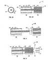
- Fig. 7shows an exploded cross-sectional view of yet another variation on pre-stressed antenna assembly having an access channel defined along the side of the antenna.
- Fig. 8shows a pre-stressed monopole variation of a microwave antenna assembly.
- Fig. 27shows an isometric exploded view of another variation on attaching the distal portion by anchoring the inner conductor within a splittable distal portion.
- variation 130 in Fig. 7shows an alternate distal end 132 which defines channel 138 for receiving inner conductor 92 but which also defines access channel 140 extending from a side surface of distal end 132 to channel 138.
- Access channel 140allows for access to inner conductor 92 to affix it to distal end 132 while allowing for tapered end 134 to terminate at sharpened tip 136.
- a single channelis shown in this variation, multiple channels may be incorporated into the design at various locations.
- FIG. 17shows a crimped or overlapping variation 290.
- Proximal portion 292is preferably attached to distal tip or portion 294 by inner conductor 302 and by having a distal end section of the proximal portion 292 crimped and portion 294 maintained in position via a molded material 300, which is also preferably dielectric such as a biocompatible thermoset plastic or polymer (including any of the dielectric materials discussed herein).
Landscapes
- Health & Medical Sciences (AREA)
- Surgery (AREA)
- Life Sciences & Earth Sciences (AREA)
- Engineering & Computer Science (AREA)
- Medical Informatics (AREA)
- Molecular Biology (AREA)
- Nuclear Medicine, Radiotherapy & Molecular Imaging (AREA)
- Veterinary Medicine (AREA)
- Biomedical Technology (AREA)
- Heart & Thoracic Surgery (AREA)
- Physics & Mathematics (AREA)
- Otolaryngology (AREA)
- Animal Behavior & Ethology (AREA)
- General Health & Medical Sciences (AREA)
- Public Health (AREA)
- Electromagnetism (AREA)
- Plasma & Fusion (AREA)
- Surgical Instruments (AREA)
- Radiation-Therapy Devices (AREA)
- Thermotherapy And Cooling Therapy Devices (AREA)
Description
- This application claims the benefit of priority to
U.S. Patent Application Serial No. 10/272,058 U.S. Patent Application Serial No. 10/052,848 filed November 2, 2001 . - The invention relates generally to microwave antenna probes which may be used in tissue ablation applications. More particularly, the invention relates to microwave antennas which may be inserted directly into tissue for diagnosis and treatment of diseases.
- In the treatment of diseases such as cancer, certain types of cancer cells have been found to denature at elevated temperatures which are slightly lower than temperatures normally injurious to healthy cells. These types of treatments, known generally as hyperthermia therapy, typically utilize electromagnetic radiation to heat diseased cells to temperatures above 41°C while maintaining adjacent healthy cells at lower temperatures where irreversible cell destruction will not occur. Other procedures utilizing electromagnetic radiation to heat tissue also include ablation and coagulation of the tissue. Such microwave ablation procedures, e.g., such as those performed for menorrhagia, are typically done to ablate and coagulate the targeted tissue to denature or kill it. Many procedures and types of devices utilizing electromagnetic radiation therapy are known in the art. Such microwave therapy is typically used in the treatment of tissue and organs such as the prostate, heart, and liver.
- One non-invasive procedure generally involves the treatment of tissue (e.g., a tumor) underlying the skin via the use of microwave energy. The microwave energy is able to non-invasively penetrate the skin to reach the underlying tissue. However, this non-invasive procedure may result in the unwanted heating of healthy tissue. Thus, the non-invasive use of microwave energy requires a great deal of control. This is partly why a more direct and precise method of applying microwave radiation has been sought.
- Presently, there are several types of microwave probes in use, e.g., monopole, dipole, and helical. One type is a monopole antenna probe, which consists of a single, elongated microwave conductor exposed at the end of the probe. The probe is sometimes surrounded by a dielectric sleeve. The second type of microwave probe commonly used is a dipole antenna, which consists of a coaxial construction having an inner conductor and an outer conductor with a dielectric separating a portion of the inner conductor and a portion of the outer conductor. In the monopole and dipole antenna probe, microwave energy generally radiates perpendicularly from the axis of the conductor.
- The typical microwave antenna has a long, thin inner conductor which extends along the axis of the probe and is surrounded by a dielectric material and is further surrounded by an outer conductor around the dielectric material such that the outer conductor also extends along the axis of the probe. In another variation of the probe which provides for effective outward radiation of energy or heating, a portion or portions of the outer conductor can be selectively removed. This type of construction is typically referred to as a "leaky waveguide" or "leaky coaxial" antenna. Another variation on the microwave probe involves having the tip formed in a uniform spiral pattern, such as a helix, to provide the necessary configuration for effective radiation. This variation can be used to direct energy in a particular direction, e.g., perpendicular to the axis, in a forward direction (i.e., towards the distal end of the antenna), or a combination thereof.
- Invasive procedures and devices have been developed in which a microwave antenna probe may be either inserted directly into a point of treatment via a normal body orifice or percutaneously inserted. Such invasive procedures and devices potentially provide better temperature control of the tissue being treated. Because of the small difference between the temperature required for denaturing malignant cells and the temperature injurious to healthy cells, a known heating pattern and predictable temperature control is important so that heating is confined to the tissue to be treated. For instance, hyperthermia treatment at the threshold temperature of about 41.5°C generally has little effect on most malignant growths of cells. However, at slightly elevated temperatures above the approximate range of 43°C to 45°C, thermal damage to most types of normal cells is routinely observed; accordingly, great care must be taken not to exceed these temperatures in healthy tissue.
- However, many types of malignancies are difficult to reach and treat using non-invasive techniques or by using invasive antenna probes designed to be inserted into a normal body orifice, i.e., a body opening which is easily accessible. These types of conventional probes may be more flexible and may also avoid the need to separately sterilize the probe; however, they are structurally weak and typically require the use of an introducer or catheter to gain access to within the body. Moreover, the addition of introducers and catheters necessarily increase the diameter of the incision or access opening into the body thereby making the use of such probes more invasive and further increasing the probability of any complications that may arise.
- Structurally stronger invasive probes exist and are typically long, narrow, needle-like antenna probes which may be inserted directly into the body tissue to directly access a site of a tumor or other malignancy. Such rigid probes generally have small diameters which aid not only in ease of use but also reduce the resulting trauma to the patient. A convenience of rigid antenna probes capable of direct insertion into tissue is that the probes may also allow for alternate additional uses given different situations. However, such rigid, needle-like probes commonly experience difficulties in failing to provide uniform patterns of radiated energy; they fail to provide uniform heating axially along and radially around an effective length of the probe; and it is difficult to otherwise control and direct the heating pattern when using such probes.
- Accordingly, there remains a need for a microwave antenna probe which overcomes the problems discussed above. There also exists a need for a microwave antenna probe which is structurally robust enough for direct insertion into tissue without the need for additional introducers or catheters and which produces a controllable and predictable heating pattern.
WO 95/18575 A1 - The scope of the invention is defined in the appended claims.
- To improve the energy focus of an antenna assembly, an electrical choke may be used in any of the variations described herein to contain returning currents to the distal end of the antenna assembly. Generally, the choke may be disposed on top of a dielectric material on the antenna proximally of the radiating section. The choke is preferably comprised of a conductive layer and may be further covered by a tubing or coating to force the conductive layer to conform to the underlying antenna.
- Additionally, variations on the choke, the tubing or coating, any sealant layers, as well as other layers which may be disposed over the antenna assembly may be used. Certain layers, e.g., a heatshrink layer disposed over the antenna assembly, may have wires or strands integrated within the layer to further strengthen the antenna assembly. Kevlar wires, for instances, may be integrally formed into the layer and oriented longitudinally with the antenna axis to provide additional strength.
- In use, to facilitate insertion of a microwave antenna into tissue, various ablative tips may be utilized. For example, one not part of the invention may utilize an antenna which is insulated along its length except at the distal tip. The distal tip may be energized by RF energy delivered through, e.g., the inner conductor. During antenna deployment, RF energy may be applied continuously or selectively to the exposed distal tip to facilitate antenna insertion by using the RF energized tip to cut through the tissue as the antenna is advanced. The present invention utilizes an inner conductor which may be slidably disposed within a lumen through the antenna. As the antenna is advanced through the tissue, when resistance is encountered the inner conductor, which may be attached to an RF generator, may be advanced distally within the lumen to extend at least partially out of the distal tip of the antenna. RF energy may then be applied such that the energized inner conductor facilitates antenna advancement by cutting the tissue.
- Any of the antenna variations described herein may be utilized in a variety of methods to effect tissue treatment. For instance, in one variation, a single antenna may be used to treat the tissue in a single location. In another variation, a single antenna may be positioned within a first region of tissue for treatment, then the antenna may be removed and positioned in another region of tissue, and so on for any number of times and positions, until satisfactory treatment is effected. In yet another variation, multiple antennas may be used simultaneously to effect treatment to a region of tissue. In this variation, the simultaneous use of multiple antennas may effectively create a combined treatment or ablation field which is larger than an ablation field that a single antenna used atone or sequentially may create. In yet another variation, multiple antennas may be used together but the power provided to each may be cycled between the antennas in an unlimited number of combinations through the use of multiplexing methods. Such a use may reduce the overall power of the system for treatment while effectively treating the tissue region of interest.
Fig. 1 shows a representative diagram of a variation of a microwave antenna assembly.Figs. 2A and 2B show an end view and a cross-sectional view, respectively, of a conventional dipole microwave antenna assembly.Fig. 3 shows an exploded cross-sectional view of a variation on a pre-stressed antenna assembly.Fig. 4 shows the assembled pre-stressed antenna assembly ofFig. 3 and the directions of stress loads created within the assembly.Fig. 5 shows another variation of pre-stressed antenna assembty haying a sharpened distal tip.Fig. 6 shows an exploded cross-sectional view of another variation on pre-stressed antenna assembly having a non-unilform junction member.Fig. 7 shows an exploded cross-sectional view of yet another variation on pre-stressed antenna assembly having an access channel defined along the side of the antenna.Fig. 8 shows a pre-stressed monopole variation of a microwave antenna assembly.Fig. 9A shows a side view of another variation on a pre-stressed antenna assembty having an electrical choke.Fig. 9B shows a cross-sectional view of the assembly ofFig. 9A .Fig. 10 shows a detailed view of a variation on the radiating portion ofFig. 9B .Fig. 11 shows a detailed view of a variation on the transition from the radiating portion to the electrical choke ofFig. 9B .Fig. 12 shows a detailed view of a variation on the different layers within the electrical choke ofFig. 9B .Fig. 13 shows a detailed view of a variation on the feedline ofFig. 9B .Fig. 14 shows an isometric view of a sectioned antenna assembly having a layer, such as a heatshrink layer, formed with wires or strands longitudinally orientated within the layer.Fig. 15 shows an exploded cross-sectional side view of a variation of the microwave antenna assembly having a mechanically threaded interface.Fig. 16 shows an exploded cross-sectional side view of another variation of the antenna assembly also having a mechanically threaded interface.Fig. 17 shows a cross-sectional side view of a crimped or overlapping variation of the antenna assembly.Fig. 18 shows a cross-sectional side view of an antenna assembly where the proximal portion may be configured to receive and hold the distal portion in an overlapping joint.Fig. 19 shows an exploded cross-sectional side view of a variation of the antenna assembly having an interfitting joint with an overlapping junction member.Fig. 20 shows a cross-sectional side view of an antenna assembly with two variations on the distal portion joint for interfitting with the proximal portion.Figs. 21A and 21B show the corresponding end views of the proximal portion fromFig. 20 with two variations for interfitting with the distal portions.Fig. 22 shows an exploded cross-sectional side view of another variation where the antenna may be assembled using overlapping interference-fitted joints.Fig. 23 shows another variation in an exploded cross-sectional side view of an antenna assembled via a junction member and multiple pins.Fig. 24 shows an exploded cross-sectional side view of another variation in which the distal portion may have a plurality of projections which interfit with corresponding depressions within the proximal portion.Fig. 25 shows another variation in which the projections and their corresponding interfitting depressions may have corresponding access channels defined in the proximal portion through which the distal portion may be welded, soldered, brazed, or adhesively affixed to the proximal portion.Fig. 26 shows a side view of a variation on attaching the distal portion to the inner conductor by a screw-on method.Fig. 27 shows an isometric exploded view of another variation on attaching the distal portion by anchoring the inner conductor within a splittable distal portion.Fig. 28 shows an exploded side view of a multi-sectioned distal portion variation.Fig. 29 shows a cross-sectioned side view of an alternative distal portion having an arcuate or curved sloping face to facilitate antenna assembly as well as entry into tissue.Fig. 30 shows an assembled cross-sectional side view of a representative antenna assembly having a constant diameter over the proximal and distal portions.Fig. 31 shows the antenna ofFig. 30 but with the distal portion having a diameter larger than the diameter of the proximal portion.Fig. 32 shows the antenna ofFig. 30 but with the distal portion having a diameter smaller than the diameter of the proximal portion.Fig. 33 shows an antenna variation which may be used with RF energy to facilitate insertion into tissue or to cut through obstructive tissue.Figs. 34A and 34B show another variation which may also be used to deliver RF energy.Figs. 35A and 35B show an isometric and end view, respectively, of one variation in using a single antenna.Figs. 36A and 36B show an isometric and end view, respectively, of another variation in using a single antenna in multiple positions.Figs. 37A and 37B show an isometric and end view, respectively, of yet another variation in using multiple antennas in multiple positions.Fig. 38 shows a schematic illustration of a variation for a channel splitter assembly for creating multiple channels using a single source.- In invasively treating diseased areas of tissue in a patient, trauma may be caused to the patient resulting in pain and other complications. Various microwave antenna assemblies, as described herein, are less traumatic than devices currently available and as described in further detail below, methods of manufacturing such devices are also described. Generally, an apparatus of the present invention allows for the direct insertion of a microwave antenna into tissue for the purposes of diagnosis and treatment of disease.
Fig. 1 shows a representative diagram of a variation of amicrowave antenna assembly 10 of the present invention. Theantenna assembly 10 is generally comprised of radiatingportion 12 which may be connected by feedline 14 (or shaft) viacable 15 toconnector 16, which may further connect theassembly 10 to apower generating source 28, e.g., a generator.Assembly 10, as shown, is a dipole microwave antenna assembly, but other antenna assemblies, e.g., monopole or leaky wave antenna assemblies, may also utilize the principles set forth herein.Distal portion 20 of radiatingportion 12 preferably has a taperedend 24 which terminates at atip 26 to allow for insertion into tissue with minimal resistance. In those cases where the radiatingportion 12 is inserted into a pre-existing opening,tip 26 may be rounded or flat. - In some applications a microwave antenna requires adequate structural strength to prevent bending of the antenna, e.g., where the antenna is directly inserted into tissue, where the antenna undergoes bending moments after insertion, etc. Accordingly, there are various configurations to increase the antenna strength without compromising desirable radiative properties and the manufacturability of such an antenna. One configuration involves placing the antenna assembly under a compressive load to stiffen the radiating portions. Another configuration involves mechanically fastening, e.g., in a screw-like manner, the radiating portions together to provide a joint which will withstand bending moments. A further configuration may also involve creating overlapping joints between the radiating portions of the antenna assembly to provide a highstrength antenna. Furthermore, alternate configurations of attaching a distal tip or distal radiating portion to an antenna may be utilized to further increase the antenna strength.
- Generally, the
antenna assembly 10 inFig. 1 shows a variation where a compressive load may be used to increase antenna strength.Proximal portion 22 is located proximally ofdistal portion 20, andjunction member 18 is preferably located between both portions such that a compressive force is applied by distal andproximal portions junction member 18. Placing distal andproximal portions assembly 10 to maintain a stiffness that is sufficient to allow for unaided insertion into the tissue while maintaining a minimal antenna diameter, as described in detail below. Feedline 14 may electrically connectantenna assembly 10 viacable 15 togenerator 28 and usually comprises a coaxial cable made of a conductive metal which may be semi-rigid or flexible.Feedline 14 may also have a variable length from a proximal end of radiatingportion 12 to a distal end ofcable 15 ranging between about 25,4 mm - 254 mm (1 to 10 inches). Most feedlines may be constructed of copper, gold, or other conductive metals with similar conductivity values, butfeedline 14 is preferably made of stainless steel. The metals may also be plated with other materials, e.g., other conductive materials, to improve their properties, e.g., to improve conductivity or decrease energy loss, etc. Afeedline 14, such as one made of stainless steel, preferably has an impedance of about 50 Ω and to improve its conductivity, the stainless steel may be coated with a layer of a conductive material such as copper or gold. Although stainless steel may not offer the same conductivity as other metals, it does offer strength required to puncture tissue and/or skin.Fig. 2A and 2B show an end view and a cross-sectional view, respectively, of a conventional dipolemicrowave antenna assembly 30. As seen,antenna assembly 30 has aproximal end 32 which may be connected to afeedline 14, as further discussed herein, and terminates atdistal end 34. The radiating portion ofantenna 30 comprisesproximal radiating portion 36 anddistal radiating portion 38.Proximal radiating portion 36 may typically have anouter conductor 42 and aninner conductor 44, each of which extends along a longitudinal axis. Between the outer andinner conductors dielectric material 46 which is also disposed longitudinally between theconductors Distal portion 48 is also made from a conductive material, as discussed below. Proximal anddistal radiating portions junction 40, which is typically made of a dielectric material, e.g., adhesives, and are also supported byinner conductor 44 which runs through junction opening 50 and at least partially throughdistal portion 48. However, as discussed above, the construction ofconventional antenna assembly 30 is structurally weak atjunction 40.- In operation, microwave energy having a wavelength, λ, is transmitted through
antenna assembly 30 along both proximal anddistal radiating portions antenna assembly 30 radiates and the surrounding medium is subsequently heated. Anantenna assembly 30 through which microwave energy is transmitted at a wavelength, λ, may have differing effective wavelengths, λeff, depending upon the surrounding medium, e.g., liver tissue, as opposed to, e.g., breast tissue. Also affecting the effective wavelength, λeff, are coatings which may be disposed overantenna assembly 30, as discussed further below. Fig. 3 shows an exploded cross-sectional view of a variation onpre-stressed antenna assembly 60 made at least in part according to the present invention. In makingantenna assembly 60,junction member 62 may be placed aboutinner conductor 44 throughjunction opening 64.Distal portion 48 may be placed overinner conductor 44 and then compressed such thatjunction member 62 is placed under a compressive load generated betweenproximal radiating portion 36 anddistal radiating portion 38 to createpre-stressed antenna assembly 70, as shown inFig. 4 .Antenna assembly 70 may have an overall length of about 36 mm (1. 42 inches) and an outer diameter of about 2,32 mm (0.091 inches). The pre-stressed loading condition onantenna assembly 70 preferably exists whenassembly 70 is under a state of zero external stress, that is, whenassembly 70 is not acted upon by any external forces, e.g., contact with tissue, external bending moments, etc.- The compression load is preferably first created by feeding
distal portion 48 overinner conductor 44 untiljunction member 62 is under compression, theninner conductor 44 is preferably affixed todistal portion 48 to maintain the compression load onjunction member 62. Some clearance may be necessary betweenjunction member 62 andinner conductor 44 to avoid any interference resistance between the two.Inner conductor 44 may be affixed todistal portion 48 alonginterface 72 by a variety of methods, such as welding, brazing, soldering, or by use of adhesives. The compression loading occurs such that whileinner conductor 44 is placed under tension alongdirection 76,distal portion 48 places the outer portions ofjunction member 62 under compression alongdirections 74.Inner conductor 44 may be heated prior to affixing it todistal portion 48 by any number of methods because heatinginner conductor 44 may expand the conductor in a longitudinal direction (depending upon the coefficient of thermal expansion of the inner conductor 44). - For example, heating
inner conductor 44 may be accomplished during the welding or soldering procedure. Upon cooling,inner conductor 44 may contract accordingly and impart a tensile force upon theconductor 44 while simultaneously pullingjunction member 62 into compression. To allow the compression loading to transfer efficiently throughassembly 70,junction member 62 is preferably made of a dielectric material which has a sufficiently high compressive strength and high elastic modulus, i.e., resistant to elastic or plastic deformation under a compression load. Therefore,junction member 62 is preferably made from materials such as ceramics, e.g., Al2O3, Boron Nitride, stabilized Zirconia, etc. Alternatively, ajunction member 62 made of a metal and sufficiently coated with a dielectric or polymer may be used, provided the dielectric coating is sufficiently thick to provide adequate insulation. To prevent energy from conducting directly into the tissue during use, a dielectric layer having a thickness between about 0,00254 mm - 0,00762 mm (0.0001 to 0.003 inches), may be coated directly overantenna assembly 70. The dielectric coating may increase the radiated energy and is preferably made from a ceramic material, such as Al2O3, TiO2, etc., and may also be optionally further coated with a lubricious material such as Teflon, polytetrafluoroethylene (PTFE), or fluorinated ethylene propylene (FEP), etc. In addition to the dielectric coating, a sealant layer may also be coated either directly over theantenna assembly 70, or preferably over the dielectric layer to provide a lubricious surface for facilitating insertion into a patient as well as to prevent tissue from sticking to theantenna assembly 70. The sealant layer may be any variety of polymer, but is preferably a thermoplastic polymer and may have a thickness varying from a few angstroms to as thick as necessary for the application at hand. Varying these coating thicknesses overantenna assembly 70 may vary the effective wavelengths, λeff, of the radiation being transmitted by the antenna. Thus, one may vary the coating thicknesses over theassembly 70 to achieve a predetermined effective wavelength depending upon the desired results. Fig. 5 shows another variation ofpre-stressed antenna assembly 80. This variation also hasproximal radiating portion 82 attached todistal radiating portion 84 withjunction member 86 therebetween under a compression load, as described above.Proximal radiating portion 82 may haveouter conductor 88 andinner conductor 92 extending longitudinally withdielectric material 90 disposed in-betweenconductors distal end 94 havingdistal radiating portion 84 with taperedend 96 terminating attip 98, which is preferably sharpened to allow for easy insertion into tissue. A preferable method of optimizing the amount of radiated energy fromassembly 80 may include adjusting the length ofproximal radiating portion 82 to correspond to a length of λ/4 of the radiation being transmitted throughassembly 80, and likewise adjusting a cumulative (or overall) length ofdistal radiating portion 84 andjunction 86 to also correspond to a length of λ/4. Adjusting the lengths of proximal anddistal radiating portions distal radiating portions antenna assembly 80 is radiating energy, the ablation field is variable 3-dimensionally and may be roughly spherical or ellipsoid and centers onjunction 86 and extends to the ends of the proximal anddistal radiating portions - The location of
tip 98 may be proportional to a distance of λ/4 of the radiation being transmitted throughassembly 80, but becausetip 98 terminates attapered end 96, the angled surface oftaper 96 may be taken into account. Thus, the total distance along the outer surfaces ofassembly 80 from B to C plus the distance from C to D may accord to the distance of λ/4. The length ofproximal radiating portion 82, i.e., the distance along the outer surface ofassembly 80 from A to B, may also accord to the distance of λ/4, as above. Although it is preferable to have the length of the radiating portion of the antenna accord with a distance of the wavelength, λ, it is not necessary for operation of the device, as described above. That is, an antenna assembly having a radiating portion with a length in accordance with a first wavelength may generally still be used for transmitting radiation having a second wavelength, or third wavelength, or so on, although with a possible reduction in efficiency. Fig. 6 shows an exploded cross-sectional view of another variation onpre-stressed antenna assembly 100.Assembly 100 shows a variation ofjunction member 102 which has a radial thickness which is non-uniform about a longitudinal axis as defined byjunction member 102. The proximal portion is comprised ofouter conductor 110,inner conductor 112,dielectric material 114, as above. However,junction 102 is shown in this variation as a stepped member having at least two different radiuses. In other variations, the junction may be curved or have multiple steps. Central radius 104 ofjunction member 102 is shown as having a diameter similar to that ofouter conductor 110 anddistal portion 120. Steppedradius 106, which is preferably smaller than central radius 104, may be symmetrically disposed both proximally and distally of central radius 104. To accommodate steppedjunction member 102 during the assembly ofantenna 100, receivingcavity 116 may be made indielectric material 114 and receivingcavity 118 may be made indistal portion 120 to allow for the interfitting of the respective parts. Such a stepped design may allow for the compression load to be concentrated longitudinally upon the central radius 104 ofjunction member 102 to allow for the efficient transfer of the load along the proximal portion.- In addition to stepped
junction member 102,Fig. 6 also showschannel 122 extending longitudinally fromdistal tip 124 to receivingcavity 118. Onceinner conductor 112 may be placed throughjunction opening 108 and intodistal portion 120, either partially or entirely therethrough,channel 122 may allow for access toinner conductor 112 for the purpose of affixing it todistal portion 120. Affixinginner conductor 112 may be done to place it under tension by any of the methods as described above, such as welding or soldering. - However, having
channel 122 extend from thedistal tip 124 toinner conductor 112 may limit the sharpness oftip 124. Accordingly,variation 130 inFig. 7 shows an alternatedistal end 132 which defineschannel 138 for receivinginner conductor 92 but which also definesaccess channel 140 extending from a side surface ofdistal end 132 tochannel 138.Access channel 140 allows for access toinner conductor 92 to affix it todistal end 132 while allowing fortapered end 134 to terminate at sharpenedtip 136. Although a single channel is shown in this variation, multiple channels may be incorporated into the design at various locations. - While most of the variations described above are related to dipole antenna assemblies,
Fig. 8 showsmonopole antenna assembly 150 made at least in part according to the present invention. As shown, there may be asingle radiating portion 152 which preferably has a length corresponding to a length of λ/2, rather than λ/4, of the radiation being transmitted throughassembly 150. As above,monopole assembly 150 may apply a compressive load uponjunction member 154 between radiatingportion 152 andproximal end 156. The principles of having an antenna length correspond to a length of λ/2 or λ/4, as well as having tapered distal ends or tips on the distal portion, may be utilized not only with antennas assembled using compression methods, but these principles may be used with any of the variations described herein. - To improve the energy focus of an antenna assembly, an electrical choke may also be used to contain returning currents to the distal end of the antenna. Generally, the choke may be disposed on the antenna proximally of the radiating section. The choke is preferably placed over a dielectric material which may be disposed over the antenna. The choke is preferably a conductive layer and may be further covered by a tubing or coating to force the conductive layer to conform to the underlying antenna, thereby forcing an electrical connection (or short) more distally and closer to the radiating section. The electrical connection between the choke and the underlying antenna may also be achieved by other connection methods such as soldering, welding, brazing, crimping, use of conductive adhesives, etc. The following description is directed towards the use of a choke on a compression antenna variation for illustration purposes only; however, the choke may also be used with any of the antenna variations described below.
Fig. 9A shows a side view of a variation onpre-stressed antenna assembly 160 with an electrical choke andFig. 9B showscross-sectioned side view 9B-9B fromFig. 9A . Similar to the antenna assemblies above,assembly 160shows radiating portion 162 electrically attached via feedline (or shaft) 164 to a proximally locatedcoupler 166.Detail 174 of radiatingportion 162 anddetail 180 offeedline 164 are described in further detail below. Radiatingportion 162 is shown withsealant layer 168 coated oversection 162.Electrical choke 172 is shown partially disposed over a distal section offeedline 164 to formelectrical choke portion 170, which is preferably located proximally of radiatingportion 162.Details choke portion 170 are described in further detail below.Fig. 10 showsdetailed view 174 fromFig. 9B of a variation on a pre-stressed antenna section. As seen,distal radiating portion 190 andproximal radiating portion 192 are located in their respective positions aboutjunction member 194, which in this variation is shown as a stepped member.Proximal radiating portion 192 is further shown havingouter conductor 196 preferably disposed concentrically aboutinner conductor 198 with dielectric 200 placed in-between outer andinner conductors Inner conductor 198 may be fed throughjunction member 194 and intodistal radiating portion 190 to be affixed by weld orsolder 202 todistal radiating portion 190 viaaccess channel 204, which is shown to extend from a distal end ofinner conductor 198 to an outer surface ofportion 190. As described above,inner conductor 198 may be heated to longitudinally expand it prior to affixing it todistal portion 190. Asinner conductor 198 cools, a tensile force is imparted ininner conductor 198 which draws the distal andproximal portions junction member 194, preferably at the junction-to-distal portion interface 206. Optionally,dielectric layer 208, which may be a ceramic material such as Al2O3, may be coated over the radiating antenna portion. Moreover, a lubricious layer such as Teflon, may also be coated over the antenna portion as well along withdielectric layer 208. Afurther sealant layer 210 may optionally be coated overdielectric layer 208 as well.Sealant layer 210 may be made from a variety of thermoplastic polymers, e.g., heat shrink polymers, such as polyethylene (PE), polyethylene terephthalate (PET), polytetrafluoroethylene (PTFE), fluorinated ethylene propylene (FEP), perfluoroalkoxy (PFA), chlorotrifluoroethylene (CTFE), ethylene chlortrifluoroethylene (ECTFE), and ethylene tetrafluoroethylene (ETFE). The description is directed towards the use of dielectric and sealant layers on a compression antenna variation for illustration purposes only; however, the uses of dielectric and sealant layers may also be used with any of the antenna variations described below.Fig. 11 showsdetailed view 176 fromFig. 9B of a variation on the transition toelectrical choke portion 170.Electrical choke 172 may be disposed proximally ofsealant layer 210 orproximal radiating portion 192. Although shown with a gap betweenchoke 172 andsealant layer 210 in this variation, the two may touch or overlap slightly.Fig. 12 shows a moredetailed view 178 of the various layers which may compriseelectrical choke 172. In this variation, a firstinner dielectric layer 220 may be disposed over the antenna assembly. The firstinner dielectric layer 220 may be made from any of the various thermoplastic polymers, ceramics, or other coatings, as described above. A second inner dielectric layer 222 may optionally be disposed over firstinner dielectric layer 220 and may be made from the same or similar material as firstinner dielectric layer 220. Conductive layer 224 may then be disposed over the dielectric layers. Conductive layer 224 is preferably a conductive coating, a conductive foil material, e.g., copper foil, or a metal tubing and electrically contactsouter conductor 196 at some location alongchoke 172 proximally of radiatingportion 162.Variation 160 illustrates electrical contact between conductive layer 224 andouter conductor 196 indetail 178 occurring at the proximal location ofelectrical choke portion 170, but choke 172 may be formed without forcing contact betweenouter conductor 196 with layer 224 provided the length ofchoke 172 is chosen appropriately. For instance, choke 172 having a sufficiently long length, e.g., a length of λ/2, may be used without having to force contact between the layers. Outerdielectric layer 226 may be disposed upon conductive layer 224. Outerdielectric layer 226 may also be made of any of the various polymers as described above and is preferably a heat shrinkable layer that may force conductive layer 224 to conform more closely to the underlying layers to not only force a better electrical connection, but also to reduce the overall diameter of the antenna section.Fig. 13 showsdetailed view 180 fromFig. 9B of a variation on the feedline. As shown,feedline 164 may be a simple coaxial cable whereouter conductor 196,inner conductor 198, and dielectric 200 extend throughout the feedline. Outerdielectric layer 226 may also extend down overfeedline 164 and even over the entire antenna assembly.- Further steps may optionally be taken to further increase the strength of an antenna assembly by altering any of the layers, such as
sealant layer 210 or any of the other heatshrink layers discussed above.Fig. 14 shows one example ofantenna section 230 where wires orstrands 236 may be formed within or on thelayers 232 to add strength. Thewires 236 may be formed within thelayer 232 and are preferably orientated longitudinally along the length ofantenna section 230 such that the bending strength of the antenna is increased. Thelayers 232 may be formed overouter conductor 234, as described above, andwire 236 may be made of any high-strength material, e.g., Kevlar, metals, etc. Metal wires may be used provided they are well insulated bylayers 232. - Aside from using a compressive load to increase antenna strength, as described above, alternative methods may be employed for increasing antenna strength to withstand direct insertion into tissue. An alternative variation may include assembling an antenna using mechanical fastening methods.
Fig. 15 , for example, shows a cross-sectioned variation of a mechanically threaded interface or "screw-on"variation 240 as an exploded assembly. As seen,proximal portion 242 may be connected todistal portion 244 by using ajunction member 246 having first and secondjunction mating sections Junction member 246 is preferably comprised of any of the dielectric materials as described above. Alternatively, a dielectric coating or layer may also be applied to the inside ofchannels contacts junction member 246. First andsecond mating sections section section Proximal portion 242 may have a receiving cavity orchannel 248 which is threaded 250 at a predetermined pitch to correspond to the pitch and angle of the threading 256 onfirst mating section 252. Likewise,distal portion 244 may have a receiving cavity orchannel 260 which is threaded 262 at a predetermined pitch to correspond to the pitch and angle of the threading 258 onsecond mating section 254. Having opposed pitch angles may be done to ensure a secure fit or joint whenvariation 240 is assembled by screwingproximal portion 242 anddistal portion 244 together ontojunction member 246.- A further screw-on
variation 270 is shown inFig. 16 . Here,proximal portion 272 may have aproximal mating section 274 which is threaded 276 at a predetermined pitch and angle to correspondingly screw intodistal portion 282 via threaded receivingchannel 278.Channel 278 preferably has threading 280 which matches threading 276 onmating section 274 to ensure a tight fit and a secure joint. Althoughvariation 270 shows amating section 274 onproximal portion 272 and receivingchannel 278 indistal portion 282, a mating section may instead be located ondistal portion 282 for insertion into a corresponding receiving channel located inproximal portion 272. Preferably, a dielectric coating orlayer 284 is applied either to the inside ofchannel 278 or on the outer surface ofmating section 274 as shown (or upon both) to prevent contact between proximal anddistal portions - Another variation on assembling an antenna is by use of overlapping or interfitting joints to attach proximal and distal portions together.
Fig. 17 shows a crimped or overlappingvariation 290.Proximal portion 292 is preferably attached to distal tip orportion 294 byinner conductor 302 and by having a distal end section of theproximal portion 292 crimped andportion 294 maintained in position via a moldedmaterial 300, which is also preferably dielectric such as a biocompatible thermoset plastic or polymer (including any of the dielectric materials discussed herein). The distal end section, i.e., crimpeddielectric 296 and crimpedouter conductor 298, is preferably crimped or tapered in a reduced diameter towards the distal end while a portion ofdielectric 296 near crimpedouter conductor 298 may be partially removed to allow formaterial 300 to be formed within, as shown in the figure. While theinner conductor 302 is held between proximal anddistal portions moldable material 300 may be injection molded within a die or preform holding the assembly to form a unitary structure with bothportions Material 300 may also be shaped into various forms depending upon the desired application, such as a tapering distal end, as shown in theFig. 17 . Fig. 18 shows anothervariation 310 whereproximal portion 312 is preferably configured to receive and holddistal portion 314.Proximal portion 312 may have a distal section ofdielectric material 316 removed partially to create a receivingchannel 318 withinportion 312.Distal portion 314 may be snugly placed within thischannel 318 such thatportion 314 is partially within and partially out ofdielectric material 316, as shown. Alayer 320 of thedielectric material 316 may be left betweenouter conductor 322 anddistal portion 314 to form an insulative barrier between the two. Alternatively,dielectric layer 320 may be formed of a different material thandielectric 316. To further aid inantenna 310 insertion into tissue, the distal end ofdistal portion 314, as well as the distal end ofouter conductor 322, may be tapered to facilitate insertion. The overlapping segment between proximal anddistal portions antenna 310.Fig. 19 shows afurther variation 330 of an overlapping joint for assembling the antenna.Proximal portion 332 preferably has amating channel 340 in the distal end of theportion 332 for receivingmating section 338 ofdistal portion 334. Thisvariation 330 preferably has an overlappingjunction member 336 which may be slipped overmating section 338 prior to insertion intochannel 340. Overlappingjunction member 336 is preferably a dielectric material and fits snugly betweenproximal portion 332 andmating section 338 to form an overlapping joint when the inner conductor is attached todistal portion 334, as described above.Fig. 20 shows an antenna variation where different methods of overlapping attachments may be utilized.Distal portion 350 is shown having acylindrical interfitting member 358. Theportion 350 may be inserted viamember 358 into a corresponding receivingchannel 356 preferably defined in the outer conductor ofproximal portion 354. An end view ofproximal portion 354 inFig. 21A showschannel 356 in this variation for receiving a cylindrically shapedmember 358.- Another variation is shown in
distal portion 352 where rather than having a conical interfitting member, separate pins ordowels 360 may be used to extend into receiving channels 356' of proximal portion 354'. Thesepins 360 may be integral withdistal portion 352 or they may be separate members inserted and held indistal portion 352; in either case, pins 360 are preferably made of a hard dielectric material or a metal sufficiently coated with a dielectric material for insulation. As seen inFig. 21B , which is an end view of proximal portion 354', channels 356' are shown located every 90 about portion 354'. Although four pins are used in this variation, any number of pins may be used ranging from two to several depending upon the desired strength of the antenna assembly. To support such a plurality of pins, it may be desirable to haveproximal portions 354, 354' with an outer conductor having a thickness ranging from 0.127 mm - 0,254 (0.005 to 0.010 inches). Fig. 22 shows an antenna assembly with an overlapping interference-fittedvariation 370. As seen,proximal portion 372 may be attached todistal portion 374 by ajunction member 376 which is preferably interference-fitted, i.e., frictionally-fitted, between bothportions junction member 376 may have a first and asecond section channel 378 inproximal portion 372 preferably has a diameter D and receivingchannel 380 indistal portion 374 also has a diameter D, or some diameter less than D2. Accordingly, diameter D, is some value less than D2 such that an interference fit is created betweenjunction 376 andportions distal portion 374 is frictionally held toproximal portion 372.Fig. 23 shows anotherinterfitting variation 390 utilizing ajunction member 396 which is preferably held betweenproximal portion 392 anddistal portion 394 bymultiple pins channels pins 398 extending fromproximal portion 392 may be inserted intocorresponding channels 400, and any number ofpins 402 extending fromdistal portion 394 may likewise be inserted intocorresponding channels 404.Fig. 24 shows an overlapping andinterfitting variation 410 whereproximal portion 412 has receivingchannel 416 for receivingdistal portion 414. Withinchannel 416, there may be a plurality ofdepressions 418 defined in the surface of the outer conductor. Thesedepressions 418 are preferably shaped to have a locking configuration, such as a right triangle shape, whenprojections 420, which are located radially ondistal portion 414, are inserted into and mated to depressions 418.Projections 420 are preferably protrusions which extend from a surface ofdistal portion 414 and are preferably radially disposed on the outer surface. Also, any number ofprojections 420, e.g., at least two to several, may be utilized but are preferably equally radially spaced from one another depending upon the desired strength of the overlapping joint. To facilitate insertion ofdistal portion 414 intochannel 416,projections 420 may be disposed on the ends of a number ofcorresponding support members 422 flexibly attached todistal portion 414.Support members 422 would allowprojections 420 to be retracted at least partially into the outer surface ofdistal portion 414 during insertion, and whendistal portion 414 is fully inserted intochannel 416,projections 420 may then be allowed to expand into and intimately mate with thedepressions 418 such thatdistal portion 414 is held fixed relative toproximal portion 412. A dielectric material may be coated or sprayed withinchannel 416 or ondistal portion 414 to insulate between the twoportions Fig. 25 shows afurther variation 430 of that shown inFig. 24 .Proximal portion 432 may be attached todistal portion 434 by an overlapping joint wheremating section 438 ondistal portion 434 may be inserted into receivingchannel 436. Once inserted,distal portion 434 may be held toproximal portion 432 byprojections 442 intimately mating within correspondingdepressions 444.Distal portion 434 may be made entirely of a dielectric material; alternatively,mating section 438 may be made at least partly of a dielectric while the remainder ofdistal portion 434 may be metallic. To further ensure a strong joint,depressions 444 may have a number ofaccess channels 440 preferably extending radially fromdepressions 444 defined in the surface ofchannel 436 to an outer surface ofproximal portion 432.Access channels 440 may be used to provide access to projections 442 (once mated within depressions 444) for further fixation toproximal portion 432 by welding, soldering, brazing, or by applying adhesives.- Aside from various methods of assembling microwave antennas, there are also a variety of methods for attaching the tip or distal radiating portion to a remainder of the assembly. The various methods described below may be used in any of the assembly variations discussed herein depending upon the desired antenna assembly characteristics.
Fig. 26 shows a partial assembly of a microwave antenna having adistal portion 454 which may be screwed onto theproximal portion 452 via theinner conductor 456. The distal end portion ofinner conductor 456 is preferably threaded 458 on an outer surface. Correspondingly, the receivingchannel 460 withindistal portion 454 is likewise threaded to receive the threadedportion 458 ofinner conductor 456. During assembly,distal portion 454 may be screwed ontoproximal portion 452 byinner conductor 458. Accordingly, the force with which the proximal anddistal portions distal portion 454 is screwed or advanced ontoinner conductor 456, thereby allowing the rigidity or strength of the antenna to be varied according to a desired use or application. In this variation,distal portion 454 may be made of a non-metallic material, e.g., a polymer, and attached directly toproximal portion 452; alternatively,distal portion 454 may also be made of a metallic material and used in conjunction with a dielectric junction member, as described above.Fig. 27 shows another variation for assembling a distal portion in an isometric exploded view of splittabledistal portion 470. Thedistal portion 470 may be comprised of a splittable distal portion having afirst half 472 and asecond half 474. Although shown split into twohalves distal portion 470 may be split into numerous portions, e.g., three or more. Within the adjoining surfaces, anchoringchannel 476 may be defined to receiveinner conductor 480 and may have a portion ofchannel 476 configured or enlarged to receive ananchoring element 482 for holding theinner conductor 480 distal end withindistal portion 470.Inner conductor 480 preferably has ananchoring element 482 formed on a distal end ofinner conductor 480 by rounding or flattening the distal end into anchoringelement 482 or attaching a separate anchoring mechanism onto the distal end. Onceinner conductor 480 and anchoringelement 482 are positioned within anchoringchannel 476, bothhalves anchoring element 482 therewithin. When distal portion halves 472, 474 are attached to one another, they may be aligned and positioned relative to each other by a number ofalignment projections 478 on one or bothhalves - Another variation for attaching the distal portion is shown in
Fig. 28 , which is an exploded side view ofmulti-sectioned portion 490. The distal portion may be comprised of multiple sections which may be interfitted to form the distal portion. Thus, whileproximal portion 492 and junction member 494 (which may or may not be used in this variation) are assembled as in some of the other variations, the distal portion may have afirst section 496 through whichinner conductor 506 may be passed through viaaccess channel 502. Once the distal tip ofinner conductor 506 is passed throughjunction member 494 andaccess channel 502, it may then be attached tofirst section 496 at the end ofaccess channel 502 by any of the attachment methods described above.First section 496 may then be assembled withsecond section 498 byinterfitting mating section 500 into receivingchannel 504. The use of a multi-sectioned portion such as that shown inportion 490 may enable one to first attach the proximal portion with the distal portion and variably alter the tip of the distal portion according to a desired application. - To further aid in tip or distal portion attachment to the antenna assembly, various distal portions may be used to facilitate assembly and use in a patient. As previously described, the distal tip is preferably tapered and terminates at a tip to facilitate antenna insertion into tissue with minimal resistance. Also, attaching the inner conductor to the distal portion may be facilitated by an access channel defined in the distal portion so that the inner conductor may be attached by welding, soldering, etc. within the distal portion. To further facilitate this assembly process, the distal tip may be formed into an arcuate or curved face terminating into a tip, as seen in
Fig. 29 . As shown in the cross-sectional side view ofalternate tip 510, it may have the arcuate orcurved face 512 sloping distally such thattip 514 is formed off-center from the longitudinal axis defined by the antenna to whichalternate tip 510 may be attached. Accordingly,inner conductor 518 may be routed throughaccess channel 516 and then attached by any of the methods described toalternate tip 510 thereby allowingtip 514 to be sharpened as necessary and allowing anaccess channel 516 to be maintained along the longitudinal axis of the antenna for ease of assembly. - As discussed above, the energy with a wavelength, λ, is transmitted down a microwave antenna and is subsequently radiated into the surrounding medium. In operation, microwave energy having a wavelength, λ, is transmitted through the antenna assembly along both proximal and distal radiating portions. This energy is then radiated into the surrounding medium. The length of the antenna for efficient radiation may be dependent at least on the effective wavelength, λeff, which is dependent upon the dielectric properties of the medium being radiated into. Energy having the effective wavelength radiates and the surrounding medium is subsequently heated. An antenna assembly through which microwave energy is transmitted at a wavelength, λ, may have differing effective wavelengths, λeff, depending upon whether the energy is radiated into, e.g., liver tissue, as opposed to, e.g., breast tissue. Also affecting the effective wavelength, λeff, are coatings which may be disposed over the antenna assembly.
- Accordingly, various distal portions having varying diameters are shown in
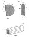
Figs. 30 to 32. Fig. 30 , for instance, shows arepresentative antenna 520 having a constant diameter fromproximal portion 522 todistal portion 524 while covered with anoptional heatshrink 526, as described above, for comparison purposes.Fig. 31 showsantenna 530 havingdistal portion 532 with a larger diameter thanproximal portion 522.Heatshrink 526 in this variation may be desirable to smooth the transition between the different diameters. On the other hand,Fig. 32 showsantenna 540 havingdistal portion 542 with a diameter that is smaller than that ofproximal portion 522. Having heatshrink 526 in this variation may also be desirable to likewise smooth the transition between the different diameters. Varying the diameters of the distal portion may change the radiative properties of the effective wavelength in addition to the different medium types being radiated into. Accordingly, the diameter of the distal portion may be varied to give a desired radiative effect for different tissue types. Besides the diameter of the distal portion, the thicknesses ofheatshrink 526 or any of the other dielectric and sealant layers, as described above, may also be varied accordingly in addition to the distal portion diameter. Although only two variations are shown inFigs. 31 and 32 , the distal tips may have a variety of configurations; for instance, it may be stepped, ramped, tapered, etc., depending upon the desired radiative effects. - As described above, the microwave antenna may be inserted directly into the tissue and into the lesion to be treated. However, during insertion, the antenna may encounter resistance from some areas of tissue, particularly in some tissue found, e.g., in the breast. When the microwave antenna encounters resistance, if force were applied, tissue damage may result or the target tissue may be inadvertently pushed away due to the differential density of the target tissue relative to the surrounding tissue. Therefore, RF energy may also be utilized with the microwave antenna for facilitating deployment within the tissue.
- In use, the RF energy may be simply left on the entire time the antenna is advanced through the tissue, or it may be applied or turned on only as needed as the antenna encounters resistance from the tissue. With the RF energy activated, the antenna may be further advanced utilizing the RF energy to cut through the obstructive tissue. Once the antenna has been desirably positioned within a lesion or region of tissue, the RF energy, if on, may be switched off and the microwave energy may be switched on to effect treatment.
- One variation of
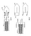
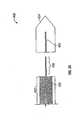
antenna assembly 550 is shown inFig. 33 .Assembly 550 may use RF energy at the distal tip of the antenna as a cutting mechanism during antenna deployment. Themicrowave antenna 552 is in an arrangement not part of the invention covered with someinsulative material 554 along most of its length, butdistal tip 556 may be uninsulated such that the RF energy may be applied thereto through the inner conductor. To utilize the RF energy cutting mechanism at the distal tip, the inner conductor may be made from Nitinol, Tungsten, stainless steel, or some other conductive metal. Antenna 552, throughcable 558, may be electrically connected to anRF generator 564 which provides the RF energy todistal tip 556 during placement and positioning ofantenna 552 within the tissue or lesion. Afterantenna 552 has been desirably positioned within the lesion,connector 560 may be disconnected fromRF cable 562 and attached to amicrowave generator 568 viamicrowave cable 566 to provide the microwave energy for effecting treatment to the tissue.- Alternatively, given the small amount of surface area of
distal tip 556, a low power RF generator may be utilized and can be built into anintegral unit 568 along with the microwave generator. Alternatively, in an arrangement not part of the invention theoptional RF generator 564 may be physically separated from the microwave generator and may be electrically connected as a separate unit, as shown. - Antenna assemblies of the present invention which utilize RF energy are shown in
Figs. 34A and 34B . In this variation,antenna assembly 570 may haveantenna body 572 define alumen 574 therethrough within whichinner conductor 576 may be slidingly positioned. During insertion of the antenna into the tissue,distal tip 578 may be used to pierce through the tissue, as seen inFig. 34A . When resistance is encountered,inner conductor 576 may be advanced distally throughlumen 574 to extend at least partially out ofdistal tip 578. To facilitate movement ofinner conductor 576 withinantenna 572, the inner surface oflumen 576 may be coated with a lubricious material or the outer surface ofinner conductor 576 may alternatively be coated. Ifinner conductor 576 is coated, a distal end portion ofinner conductor 576 may be left exposed such that RF energy may be delivered through theinner conductor 576 at this exposed end. To optimize the microwave radiation transmitted fromantenna assembly 570,electrical choke 573 may be disposed partially overantenna body 572, as shown.Electrical choke 573 may be made and utilized in any of the variations as described in detail above. - Aside from the illustrations of possible antenna deployment methods and devices described above, other variations for deployment and insertion into tissue may be utilized. Potential other methods and devices for antenna deployment and insertion may be found in co-pending U.S. Patent Application entitled "Microwave Antenna Having A Curved Configuration" filed September 15, 2002.
- In using a microwave antenna, several different methods may be utilized.
Fig. 35A shows an isometric view of onevariation 580 in which asingle antenna 582 may be utilized within the tissue.Fig. 35B shows an end view of theantenna 582 and an example of a possible resulting ablation field orregion 584 using thatsingle antenna 582. In such a case,antenna 582 may be positioned directly within the tissue to be treated. Figs. 36A and 36B show anothervariation 590 in which asingle antenna 592 may be positioned in one of several locations 592' and/or 592" about the tissue to be treated.Antenna 592 may be activated in a first position, then removed and repositioned in a second position 592' and activated, and then removed and again repositioned in athird position 592" and again activated, and so on. The order of positioning, relative placement, and depth of insertion of the antenna may be sequential or varied, and the number of times the antenna is positioned or repositioned within the tissue may also be varied depending upon the desired ablation effects. This example showsantenna 592 being positioned three times for illustrative purposes but the invention is not so limited.Fig. 36B shows an end view of the overall resultingablation field 594 due to the overlapping individual ablation fields.- Another variation for antenna use is shown in
Figs. 37A and 37B . This variation showsantenna assembly 600 in which multiple antennas may be utilized in combination with one another. This example shows first, second, andthird antennas antennas antennas Fig. 37B shows an end view of an example of a combinedablation field 608 which may result when all antennas are on simultaneously. As seen, the individual antennas may combine to form a larger and moreuniform ablation field 608. - In using multiple antennas simultaneously, the energy supplied to the antennas may alternatively be cycled or pulsed to effect a combined ablation field. Rather than using
antennas Fig. 38 schematically showschannel splitter assembly 610 which may be used to create multiple channels by using a single source with multiplexing. A singlemicrowave generator module 618 having, e.g., a 100 W output, may create a single channel A. The single channel A may be switched between several separate channel outputs A1 to AN created bychannel splitter 612. Any number of multiple outputs may be used depending upon the desired number of channels and the desired effects. In use, the output may be cycled through the range ofoutputs 616 through multiple channels A1 to AN or in any other manner depending upon the ablation field to be created. Moreover, the rate of cycling may range anywhere from several microseconds to several seconds over a treatment period of several minutes or longer.Controller 614, which is preferably in electrical communication withchannel splitter 612 may be used for several purposes. It may be used to control the cycling rate as well as the order of channels in which the output is cycled through. Moreover,controller 614 may be an automatic system or set by the technician or physician. An automatic system may be configured to detect the electrical connection to the antenna and to control the delivery of the energy to the antenna. The detection may be achieved by either a passive or active component in the system which may monitor reflections from the antenna to determine whether a proper connection is present. A controller set by the technician or physician may be configured to require manual initiation for energy delivery to begin.
Claims (6)
- A microwave antenna system for applying microwave energy therapy comprising:at least one microwave antenna (552) comprising:a proximal portion having an inner conductor (576) and an outer conductor, each extending therethrough, the inner conductor (576) disposed within the outer conductor;a distal portion (578) attached to the proximal portion such that the inner conductor (576) extends at least partially through the distal portion (578) and is slidably disposed within a lumen (574) such that the inner conductor (576) may be advanced to extend at least partially out of the distal portion (578);an energy generator in communication with a proximal end of the microwave antennathe energy generator is configured to deliver RF energy to the distal portion (578) to facilitate advancement of the microwave antenna through tissue and to deliver microwave energy to the distal portion (578) to treat tissue;characterized in that : the energy generator is configured to deliver microwave energy subsequent to the delivery of RF energy; andthe inner surface of the lumen (574) or the outer surface of the inner conductor (576) is coated with a lubricious material.
- The system of claim 1, further comprising a channel splitter (612) in electrical communication with the energy generator, wherein the channel splitter (612) is adapted to create multiple channels from a single channel received from the energy generator.
- The system of claim 2, further comprising a controller (614) in electrical communication with the channel splitter (612), wherein the controller (614) is adapted to control a cycling rate of the channel splitter (612).
- The system of claim 3, wherein the controller (614) is further adapted to detect whether an electrical connection to the antenna is present.
- The system of claim 1, further comprising a choke (573) disposed at least partially over the outer conductor.
- The system of claim 1, wherein the inner conductor (576) has an insulative coating over at least a majority of the inner conductor (576), and wherein a distal tip of the inner conductor (576) is uncovered by the insulative coating.
Applications Claiming Priority (3)
| Application Number | Priority Date | Filing Date | Title |
|---|---|---|---|
| US10/052,848US6878147B2 (en) | 2001-11-02 | 2001-11-02 | High-strength microwave antenna assemblies |
| US10/272,058US7128739B2 (en) | 2001-11-02 | 2002-10-15 | High-strength microwave antenna assemblies and methods of use |
| EP02786604.5AEP1450710B1 (en) | 2001-11-02 | 2002-10-29 | High-strength microwave antenna assemblies and methods of manufacturing |
Related Parent Applications (2)
| Application Number | Title | Priority Date | Filing Date |
|---|---|---|---|
| EP02786604.5Division | 2002-10-29 | ||
| EP02786604.5ADivision-IntoEP1450710B1 (en) | 2001-11-02 | 2002-10-29 | High-strength microwave antenna assemblies and methods of manufacturing |
Publications (2)
| Publication Number | Publication Date |
|---|---|
| EP2226030A1 EP2226030A1 (en) | 2010-09-08 |
| EP2226030B1true EP2226030B1 (en) | 2012-12-05 |
Family
ID=26731161
Family Applications (4)
| Application Number | Title | Priority Date | Filing Date |
|---|---|---|---|
| EP10004951.9AExpired - LifetimeEP2226098B1 (en) | 2001-11-02 | 2002-10-29 | High-strenght microwave antenna assemblies |
| EP17203100.7AWithdrawnEP3305231A1 (en) | 2001-11-02 | 2002-10-29 | High-strength microwave antenna assemblies |
| EP10004950AExpired - LifetimeEP2226030B1 (en) | 2001-11-02 | 2002-10-29 | High-strenght microwave antenna assemblies |
| EP02786604.5AExpired - LifetimeEP1450710B1 (en) | 2001-11-02 | 2002-10-29 | High-strength microwave antenna assemblies and methods of manufacturing |
Family Applications Before (2)
| Application Number | Title | Priority Date | Filing Date |
|---|---|---|---|
| EP10004951.9AExpired - LifetimeEP2226098B1 (en) | 2001-11-02 | 2002-10-29 | High-strenght microwave antenna assemblies |
| EP17203100.7AWithdrawnEP3305231A1 (en) | 2001-11-02 | 2002-10-29 | High-strength microwave antenna assemblies |
Family Applications After (1)
| Application Number | Title | Priority Date | Filing Date |
|---|---|---|---|
| EP02786604.5AExpired - LifetimeEP1450710B1 (en) | 2001-11-02 | 2002-10-29 | High-strength microwave antenna assemblies and methods of manufacturing |
Country Status (4)
| Country | Link |
|---|---|
| US (2) | US7128739B2 (en) |
| EP (4) | EP2226098B1 (en) |
| JP (1) | JP4437039B2 (en) |
| WO (1) | WO2003039385A2 (en) |
Families Citing this family (127)
| Publication number | Priority date | Publication date | Assignee | Title |
|---|---|---|---|---|
| US6104959A (en) | 1997-07-31 | 2000-08-15 | Microwave Medical Corp. | Method and apparatus for treating subcutaneous histological features |
| US6306132B1 (en)* | 1999-06-17 | 2001-10-23 | Vivant Medical | Modular biopsy and microwave ablation needle delivery apparatus adapted to in situ assembly and method of use |
| WO2001060235A2 (en)* | 2000-02-18 | 2001-08-23 | Fogarty Thomas J M D | Improved device for accurately marking tissue |
| US7128739B2 (en) | 2001-11-02 | 2006-10-31 | Vivant Medical, Inc. | High-strength microwave antenna assemblies and methods of use |
| US6878147B2 (en) | 2001-11-02 | 2005-04-12 | Vivant Medical, Inc. | High-strength microwave antenna assemblies |
| US6752767B2 (en) | 2002-04-16 | 2004-06-22 | Vivant Medical, Inc. | Localization element with energized tip |
| US7197363B2 (en) | 2002-04-16 | 2007-03-27 | Vivant Medical, Inc. | Microwave antenna having a curved configuration |
| GB2403148C2 (en)* | 2003-06-23 | 2013-02-13 | Microsulis Ltd | Radiation applicator |
| US7311703B2 (en)* | 2003-07-18 | 2007-12-25 | Vivant Medical, Inc. | Devices and methods for cooling microwave antennas |
| US20070016181A1 (en)* | 2004-04-29 | 2007-01-18 | Van Der Weide Daniel W | Microwave tissue resection tool |
| US7101369B2 (en) | 2004-04-29 | 2006-09-05 | Wisconsin Alumni Research Foundation | Triaxial antenna for microwave tissue ablation |
| US7467015B2 (en) | 2004-04-29 | 2008-12-16 | Neuwave Medical, Inc. | Segmented catheter for tissue ablation |
| GB2415630C2 (en) | 2004-07-02 | 2007-03-22 | Microsulis Ltd | Radiation applicator and method of radiating tissue |
| US7799019B2 (en) | 2005-05-10 | 2010-09-21 | Vivant Medical, Inc. | Reinforced high strength microwave antenna |
| GB2434314B (en) | 2006-01-03 | 2011-06-15 | Microsulis Ltd | Microwave applicator with dipole antenna |
| US8672932B2 (en) | 2006-03-24 | 2014-03-18 | Neuwave Medical, Inc. | Center fed dipole for use with tissue ablation systems, devices and methods |
| US10363092B2 (en) | 2006-03-24 | 2019-07-30 | Neuwave Medical, Inc. | Transmission line with heat transfer ability |
| US11389235B2 (en) | 2006-07-14 | 2022-07-19 | Neuwave Medical, Inc. | Energy delivery systems and uses thereof |
| US10376314B2 (en) | 2006-07-14 | 2019-08-13 | Neuwave Medical, Inc. | Energy delivery systems and uses thereof |
| CN101511295B (en) | 2006-07-14 | 2012-09-05 | 纽华沃医药公司 | Energy transfer systems and their uses |
| US20080065059A1 (en)* | 2006-09-08 | 2008-03-13 | Marc Lukowiak | Microwave devices for transcutaneous treatments |
| US8068921B2 (en) | 2006-09-29 | 2011-11-29 | Vivant Medical, Inc. | Microwave antenna assembly and method of using the same |
| BRPI0810066A2 (en) | 2007-04-19 | 2015-05-05 | The Foundry Inc | Systems and methods for creating an effect using microwave energy for specific tissue |
| WO2008131306A1 (en) | 2007-04-19 | 2008-10-30 | The Foundry, Inc. | Systems and methods for creating an effect using microwave energy to specified tissue |
| EP2767308B1 (en) | 2007-04-19 | 2016-04-13 | Miramar Labs, Inc. | Devices, and systems for non-invasive delivery of microwave therapy |
| EP3391844A1 (en) | 2007-04-19 | 2018-10-24 | Miramar Labs, Inc. | Apparatus for reducing sweat production |
| US7998139B2 (en) | 2007-04-25 | 2011-08-16 | Vivant Medical, Inc. | Cooled helical antenna for microwave ablation |
| US8353901B2 (en) | 2007-05-22 | 2013-01-15 | Vivant Medical, Inc. | Energy delivery conduits for use with electrosurgical devices |
| US9023024B2 (en) | 2007-06-20 | 2015-05-05 | Covidien Lp | Reflective power monitoring for microwave applications |
| US20090005766A1 (en)* | 2007-06-28 | 2009-01-01 | Joseph Brannan | Broadband microwave applicator |
| US8651146B2 (en) | 2007-09-28 | 2014-02-18 | Covidien Lp | Cable stand-off |
| US8292880B2 (en) | 2007-11-27 | 2012-10-23 | Vivant Medical, Inc. | Targeted cooling of deployable microwave antenna |
| EP2762199B1 (en) | 2007-12-12 | 2018-03-14 | Miramar Labs, Inc. | Systems, apparatus, methods and procedures for the noninvasive treatment of tissue using microwave energy |
| KR101826243B1 (en) | 2007-12-12 | 2018-02-06 | 미라마 랩스 인코포레이티드 | Systems, apparatus, methods and procedures for the noninvasive treatment of tissue using microwave energy |
| US8945111B2 (en)* | 2008-01-23 | 2015-02-03 | Covidien Lp | Choked dielectric loaded tip dipole microwave antenna |
| US8262703B2 (en)* | 2008-01-31 | 2012-09-11 | Vivant Medical, Inc. | Medical device including member that deploys in a spiral-like configuration and method |
| US9949794B2 (en) | 2008-03-27 | 2018-04-24 | Covidien Lp | Microwave ablation devices including expandable antennas and methods of use |
| WO2009128014A1 (en) | 2008-04-16 | 2009-10-22 | Arbel Medical Ltd | Cryosurgical instrument with enhanced heat exchange |
| US8246614B2 (en) | 2008-04-17 | 2012-08-21 | Vivant Medical, Inc. | High-strength microwave antenna coupling |
| EP2271276A4 (en) | 2008-04-17 | 2013-01-23 | Miramar Labs Inc | Systems, apparatus, methods and procedures for the noninvasive treatment of tissue using microwave energy |
| WO2009140511A1 (en) | 2008-05-14 | 2009-11-19 | J&J Solutions, Inc. | Systems and methods for safe medicament transport |
| US8059059B2 (en)* | 2008-05-29 | 2011-11-15 | Vivant Medical, Inc. | Slidable choke microwave antenna |
| US8343149B2 (en)* | 2008-06-26 | 2013-01-01 | Vivant Medical, Inc. | Deployable microwave antenna for treating tissue |
| DE102008050635A1 (en)* | 2008-10-07 | 2010-04-15 | Erbe Elektromedizin Gmbh | Method and apparatus for controlling a cooled RF ablation probe |
| US8211098B2 (en)* | 2008-08-25 | 2012-07-03 | Vivant Medical, Inc. | Microwave antenna assembly having a dielectric body portion with radial partitions of dielectric material |
| US20100087808A1 (en)* | 2008-10-03 | 2010-04-08 | Vivant Medical, Inc. | Combined Frequency Microwave Ablation System, Devices and Methods of Use |
| US9113924B2 (en) | 2008-10-17 | 2015-08-25 | Covidien Lp | Choked dielectric loaded tip dipole microwave antenna |
| US7967814B2 (en) | 2009-02-05 | 2011-06-28 | Icecure Medical Ltd. | Cryoprobe with vibrating mechanism |
| US8118808B2 (en)* | 2009-03-10 | 2012-02-21 | Vivant Medical, Inc. | Cooled dielectrically buffered microwave dipole antenna |
| US8162812B2 (en) | 2009-03-12 | 2012-04-24 | Icecure Medical Ltd. | Combined cryotherapy and brachytherapy device and method |
| US8292881B2 (en) | 2009-05-27 | 2012-10-23 | Vivant Medical, Inc. | Narrow gauge high strength choked wet tip microwave ablation antenna |
| GB2472972A (en)* | 2009-07-20 | 2011-03-02 | Microoncology Ltd | A microwave antenna |
| EP3549544B1 (en) | 2009-07-28 | 2021-01-06 | Neuwave Medical, Inc. | DEVICE FOR ABLATION |
| US8328799B2 (en) | 2009-08-05 | 2012-12-11 | Vivant Medical, Inc. | Electrosurgical devices having dielectric loaded coaxial aperture with distally positioned resonant structure |
| US8409187B2 (en)* | 2009-09-08 | 2013-04-02 | Covidien Lp | Microwave antenna probe with high-strength ceramic coupler |
| US9113925B2 (en)* | 2009-09-09 | 2015-08-25 | Covidien Lp | System and method for performing an ablation procedure |
| US8069553B2 (en) | 2009-09-09 | 2011-12-06 | Vivant Medical, Inc. | Method for constructing a dipole antenna |
| US9095359B2 (en) | 2009-09-18 | 2015-08-04 | Covidien Lp | Tissue ablation system with energy distribution |
| US8343145B2 (en)* | 2009-09-28 | 2013-01-01 | Vivant Medical, Inc. | Microwave surface ablation using conical probe |
| GB2474233A (en) | 2009-10-06 | 2011-04-13 | Uk Investments Associates Llc | Cooling pump comprising a detachable head portion |
| US20110125148A1 (en)* | 2009-11-17 | 2011-05-26 | Turner Paul F | Multiple Frequency Energy Supply and Coagulation System |
| US8551083B2 (en) | 2009-11-17 | 2013-10-08 | Bsd Medical Corporation | Microwave coagulation applicator and system |
| US9993294B2 (en)* | 2009-11-17 | 2018-06-12 | Perseon Corporation | Microwave coagulation applicator and system with fluid injection |
| US8414570B2 (en)* | 2009-11-17 | 2013-04-09 | Bsd Medical Corporation | Microwave coagulation applicator and system |
| WO2011066445A2 (en)* | 2009-11-30 | 2011-06-03 | Medwaves, Inc. | Radio frequency ablation system with tracking sensor |
| US8491579B2 (en)* | 2010-02-05 | 2013-07-23 | Covidien Lp | Electrosurgical devices with choke shorted to biological tissue |
| US20110208179A1 (en)* | 2010-02-25 | 2011-08-25 | Tyco Healthcare Group Lp | Patient Isolation in a Microwave-Radio Frequency Generator |
| US20110213353A1 (en)* | 2010-02-26 | 2011-09-01 | Lee Anthony C | Tissue Ablation System With Internal And External Radiation Sources |
| US7967815B1 (en) | 2010-03-25 | 2011-06-28 | Icecure Medical Ltd. | Cryosurgical instrument with enhanced heat transfer |
| US8409188B2 (en)* | 2010-03-26 | 2013-04-02 | Covidien Lp | Ablation devices with adjustable radiating section lengths, electrosurgical systems including same, and methods of adjusting ablation fields using same |
| US8388613B1 (en) | 2010-04-09 | 2013-03-05 | The United States Of America As Represented By The Administrator Of The National Aeronautics And Space Administration | Methods and apparatus for microwave tissue welding for wound closure |
| ES2856026T3 (en) | 2010-05-03 | 2021-09-27 | Neuwave Medical Inc | Power supply systems |
| US9561076B2 (en) | 2010-05-11 | 2017-02-07 | Covidien Lp | Electrosurgical devices with balun structure for air exposure of antenna radiating section and method of directing energy to tissue using same |
| US7938822B1 (en) | 2010-05-12 | 2011-05-10 | Icecure Medical Ltd. | Heating and cooling of cryosurgical instrument using a single cryogen |
| MX348044B (en) | 2010-05-27 | 2017-05-25 | J&J Solutions Inc | Closed fluid transfer system. |
| US8080005B1 (en) | 2010-06-10 | 2011-12-20 | Icecure Medical Ltd. | Closed loop cryosurgical pressure and flow regulated system |
| US9017319B2 (en)* | 2011-01-05 | 2015-04-28 | Covidien Lp | Energy-delivery devices with flexible fluid-cooled shaft, inflow/outflow junctions suitable for use with same, and systems including same |
| US9011421B2 (en) | 2011-01-05 | 2015-04-21 | Covidien Lp | Energy-delivery devices with flexible fluid-cooled shaft, inflow/outflow junctions suitable for use with same, and systems including same |
| US8932281B2 (en)* | 2011-01-05 | 2015-01-13 | Covidien Lp | Energy-delivery devices with flexible fluid-cooled shaft, inflow/outflow junctions suitable for use with same, and systems including same |
| US9770294B2 (en) | 2011-01-05 | 2017-09-26 | Covidien Lp | Energy-delivery devices with flexible fluid-cooled shaft, inflow/outflow junctions suitable for use with same, and systems including same |
| US9314301B2 (en) | 2011-08-01 | 2016-04-19 | Miramar Labs, Inc. | Applicator and tissue interface module for dermatological device |
| US9192438B2 (en) | 2011-12-21 | 2015-11-24 | Neuwave Medical, Inc. | Energy delivery systems and uses thereof |
| US9375274B2 (en) | 2012-01-05 | 2016-06-28 | Covidien Lp | Ablation systems, probes, and methods for reducing radiation from an ablation probe into the environment |
| US9113931B2 (en) | 2012-01-06 | 2015-08-25 | Covidien Lp | System and method for treating tissue using an expandable antenna |
| US9119648B2 (en) | 2012-01-06 | 2015-09-01 | Covidien Lp | System and method for treating tissue using an expandable antenna |
| US10076383B2 (en) | 2012-01-25 | 2018-09-18 | Covidien Lp | Electrosurgical device having a multiplexer |
| ITMO20120041A1 (en)* | 2012-02-17 | 2013-08-18 | Hs Hospital Service Spa | MICROWAVE DEVICE FOR FABRIC EXTRACTION |
| US8906008B2 (en)* | 2012-05-22 | 2014-12-09 | Covidien Lp | Electrosurgical instrument |
| US10443315B2 (en)* | 2012-11-28 | 2019-10-15 | Nextstream Wired Pipe, Llc | Transmission line for wired pipe |
| US9987087B2 (en)* | 2013-03-29 | 2018-06-05 | Covidien Lp | Step-down coaxial microwave ablation applicators and methods for manufacturing same |
| US9915103B2 (en) | 2013-05-29 | 2018-03-13 | Baker Hughes, A Ge Company, Llc | Transmission line for wired pipe |
| US10779885B2 (en) | 2013-07-24 | 2020-09-22 | Miradry. Inc. | Apparatus and methods for the treatment of tissue using microwave energy |
| WO2015017858A1 (en) | 2013-08-02 | 2015-02-05 | J&J SOLUTIONS, INC. d.b.a CORVIDA MEDICAL | Compounding systems and methods for safe medicament transport |
| US10624697B2 (en)* | 2014-08-26 | 2020-04-21 | Covidien Lp | Microwave ablation system |
| GB201418479D0 (en) | 2014-10-17 | 2014-12-03 | Creo Medical Ltd | Cable for conveying radiofrequency and/or microwave frequency energy to an electrosurgical instrument |
| AU2016323793B2 (en) | 2015-09-17 | 2021-03-11 | J&J SOLUTIONS, INC. d/b/a Corvida Medical | Medicament vial assembly |
| CA3001858C (en) | 2015-10-13 | 2021-03-23 | J&J SOLUTIONS, INC. d/b/a Corvida Medical | Automated compounding equipment for closed fluid transfer system |
| GB2543509B (en)* | 2015-10-19 | 2020-10-14 | Creo Medical Ltd | Electrosurgical instrument |
| CN113367788B (en) | 2015-10-26 | 2024-09-06 | 纽韦弗医疗设备公司 | Energy delivery systems and uses thereof |
| BR112018008233B1 (en) | 2015-10-26 | 2022-10-04 | Neuwave Medical, Inc | APPARATUS FOR FASTENING A MEDICAL DEVICE, METHOD FOR FASTENING A MEDICAL DEVICE IN A DESIRED POSITION, AND KIT |
| US10856940B2 (en)* | 2016-03-02 | 2020-12-08 | Covidien Lp | Ablation antenna including customizable reflectors |
| GB2552921A (en)* | 2016-04-04 | 2018-02-21 | Creo Medical Ltd | Electrosurgical probe for delivering RF and microwave energy |
| EP3407794A4 (en) | 2016-04-14 | 2019-11-06 | Focal Therapeutics, Inc. | TISSUE LOCATION DEVICE AND METHOD OF USE |
| US10531917B2 (en) | 2016-04-15 | 2020-01-14 | Neuwave Medical, Inc. | Systems and methods for energy delivery |
| US11197715B2 (en) | 2016-08-02 | 2021-12-14 | Covidien Lp | Ablation cable assemblies and a method of manufacturing the same |
| US11065053B2 (en) | 2016-08-02 | 2021-07-20 | Covidien Lp | Ablation cable assemblies and a method of manufacturing the same |
| US10376309B2 (en) | 2016-08-02 | 2019-08-13 | Covidien Lp | Ablation cable assemblies and a method of manufacturing the same |
| GB201614581D0 (en)* | 2016-08-26 | 2016-10-12 | Emblation Ltd | Microwave instrument |
| GB2559593B (en)* | 2017-02-10 | 2019-12-11 | Gyrus Medical Ltd | Microwave ablation applicators |
| US11103308B2 (en) | 2017-12-11 | 2021-08-31 | Covidien Lp | Reusable transmission network for dividing energy and monitoring signals between surgical devices |
| US20190201093A1 (en)* | 2018-01-03 | 2019-07-04 | Neuwave Medical, Inc. | Systems and methods for energy delivery |
| US20190246876A1 (en) | 2018-02-15 | 2019-08-15 | Neuwave Medical, Inc. | Compositions and methods for directing endoscopic devices |
| US20190247117A1 (en) | 2018-02-15 | 2019-08-15 | Neuwave Medical, Inc. | Energy delivery devices and related systems and methods thereof |
| US11672596B2 (en) | 2018-02-26 | 2023-06-13 | Neuwave Medical, Inc. | Energy delivery devices with flexible and adjustable tips |
| US20200168360A1 (en) | 2018-11-27 | 2020-05-28 | Neuwave Medical, Inc. | Systems and methods for energy delivery |
| US11832880B2 (en) | 2018-12-13 | 2023-12-05 | Neuwave Medical, Inc. | Energy delivery devices and related systems and methods thereof |
| US11832879B2 (en) | 2019-03-08 | 2023-12-05 | Neuwave Medical, Inc. | Systems and methods for energy delivery |
| CN113924057B (en)* | 2019-05-24 | 2025-01-14 | 堪萨斯州立大学研究基金会 | Minimally invasive microwave ablation device |
| US11633224B2 (en) | 2020-02-10 | 2023-04-25 | Icecure Medical Ltd. | Cryogen pump |
| DE102020203528A1 (en)* | 2020-03-19 | 2021-09-23 | Vitesco Technologies GmbH | Electrical device and method of making an electrical device |
| US11786303B2 (en)* | 2021-03-19 | 2023-10-17 | Quicker-Instrument Inc. | Microwave ablation probe |
| US20230088132A1 (en) | 2021-09-22 | 2023-03-23 | NewWave Medical, Inc. | Systems and methods for real-time image-based device localization |
| US20250152264A1 (en) | 2022-02-18 | 2025-05-15 | Neuwave Medical, Inc. | Coupling devices and related systems |
| US12426934B2 (en) | 2022-02-28 | 2025-09-30 | Icecure Medical Ltd. | Cryogen flow control |
| US12215811B2 (en) | 2022-07-18 | 2025-02-04 | Icecure Medical Ltd. | Cryogenic system connector |
| US20240285332A1 (en) | 2023-02-24 | 2024-08-29 | Neuwave Medical, Inc. | Temperature regulating devices and related systems and methods |
| USD1084316S1 (en) | 2023-11-20 | 2025-07-15 | Angiodynamics, Inc. | Ferrule |
Citations (3)
| Publication number | Priority date | Publication date | Assignee | Title |
|---|---|---|---|---|
| US5221281A (en)* | 1992-06-30 | 1993-06-22 | Valleylab Inc. | Electrosurgical tubular trocar |
| US5437662A (en)* | 1992-11-13 | 1995-08-01 | American Cardiac Ablation Co., Inc. | Fluid cooled electrosurgical cauterization system |
| WO1999042047A1 (en)* | 1998-02-19 | 1999-08-26 | Conway-Stuart Medical, Inc. | Method for electrosurgically treating a sphincter |
Family Cites Families (234)
| Publication number | Priority date | Publication date | Assignee | Title |
|---|---|---|---|---|
| US3595239A (en)* | 1969-04-04 | 1971-07-27 | Roy A Petersen | Catheter with electrical cutting means |
| US4140130A (en)* | 1977-05-31 | 1979-02-20 | Storm Iii Frederick K | Electrode structure for radio frequency localized heating of tumor bearing tissue |
| US4311154A (en)* | 1979-03-23 | 1982-01-19 | Rca Corporation | Nonsymmetrical bulb applicator for hyperthermic treatment of the body |
| US4292960A (en)* | 1979-04-30 | 1981-10-06 | Rca Corporation | Apparatus and method for application of radioactive and microwave energy to the body |
| US4557272A (en)* | 1980-03-31 | 1985-12-10 | Microwave Associates, Inc. | Microwave endoscope detection and treatment system |
| JPS5725863A (en) | 1980-07-23 | 1982-02-10 | Olympus Optical Co | Endoscope with microwave heater |
| FR2505495A1 (en) | 1981-05-05 | 1982-11-12 | Centre Nat Rech Scient | METHOD AND DEVICES FOR MEASURING TEMPERATURE OF A MICROWAVE BODY |
| US4397313A (en)* | 1981-08-03 | 1983-08-09 | Clini-Therm Corporation | Multiple microwave applicator system and method for microwave hyperthermia treatment |
| US4583589A (en)* | 1981-10-22 | 1986-04-22 | Raytheon Company | Subsurface radiating dipole |
| US5370675A (en) | 1992-08-12 | 1994-12-06 | Vidamed, Inc. | Medical probe device and method |
| US4534347A (en) | 1983-04-08 | 1985-08-13 | Research Corporation | Microwave coagulating scalpel |
| US4612940A (en)* | 1984-05-09 | 1986-09-23 | Scd Incorporated | Microwave dipole probe for in vivo localized hyperthermia |
| US4800899A (en)* | 1984-10-22 | 1989-01-31 | Microthermia Technology, Inc. | Apparatus for destroying cells in tumors and the like |
| GB2171309B (en)* | 1985-02-26 | 1988-11-02 | North China Res I Electro Opti | Microwave therapeutic apparatus |
| US4669475A (en)* | 1985-06-28 | 1987-06-02 | Bsd Medical Corporation | Apparatus and method for hyperthermia treatment |
| US4658836A (en)* | 1985-06-28 | 1987-04-21 | Bsd Medical Corporation | Body passage insertable applicator apparatus for electromagnetic |
| US4700716A (en)* | 1986-02-27 | 1987-10-20 | Kasevich Associates, Inc. | Collinear antenna array applicator |
| IL78755A0 (en) | 1986-05-12 | 1986-08-31 | Biodan Medical Systems Ltd | Applicator for insertion into a body opening for medical purposes |
| US5097845A (en) | 1987-10-15 | 1992-03-24 | Labthermics Technologies | Microwave hyperthermia probe |
| US4841988A (en) | 1987-10-15 | 1989-06-27 | Marquette Electronics, Inc. | Microwave hyperthermia probe |
| US5249585A (en)* | 1988-07-28 | 1993-10-05 | Bsd Medical Corporation | Urethral inserted applicator for prostate hyperthermia |
| FR2639238B1 (en) | 1988-11-21 | 1991-02-22 | Technomed Int Sa | APPARATUS FOR SURGICAL TREATMENT OF TISSUES BY HYPERTHERMIA, PREFERABLY THE PROSTATE, COMPRISING MEANS OF THERMAL PROTECTION COMPRISING PREFERABLY RADIOREFLECTIVE SCREEN MEANS |
| FR2693116B1 (en) | 1992-07-06 | 1995-04-28 | Technomed Int Sa | Urethral probe and apparatus for the therapeutic treatment of prostate tissue by thermotherapy. |
| US4945912A (en)* | 1988-11-25 | 1990-08-07 | Sensor Electronics, Inc. | Catheter with radiofrequency heating applicator |
| US5122137A (en) | 1990-04-27 | 1992-06-16 | Boston Scientific Corporation | Temperature controlled rf coagulation |
| JPH05506174A (en)* | 1990-09-14 | 1993-09-16 | アメリカン・メディカル・システムズ・インコーポレーテッド | Combined hyperthermia and dilatation catheter |
| US5221269A (en)* | 1990-10-15 | 1993-06-22 | Cook Incorporated | Guide for localizing a nonpalpable breast lesion |
| US5409453A (en) | 1992-08-12 | 1995-04-25 | Vidamed, Inc. | Steerable medical probe with stylets |
| US5301687A (en)* | 1991-06-06 | 1994-04-12 | Trustees Of Dartmouth College | Microwave applicator for transurethral hyperthermia |
| DE4122050C2 (en)* | 1991-07-03 | 1996-05-30 | Gore W L & Ass Gmbh | Antenna arrangement with supply line for medical heat application in body cavities |
| US6024733A (en) | 1995-06-07 | 2000-02-15 | Arthrocare Corporation | System and method for epidermal tissue ablation |
| US5697882A (en) | 1992-01-07 | 1997-12-16 | Arthrocare Corporation | System and method for electrosurgical cutting and ablation |
| US5413588A (en) | 1992-03-06 | 1995-05-09 | Urologix, Inc. | Device and method for asymmetrical thermal therapy with helical dipole microwave antenna |
| US5415666A (en)* | 1992-03-23 | 1995-05-16 | Advanced Surgical, Inc. | Tethered clamp retractor |
| US5281217A (en)* | 1992-04-13 | 1994-01-25 | Ep Technologies, Inc. | Steerable antenna systems for cardiac ablation that minimize tissue damage and blood coagulation due to conductive heating patterns |
| US5314466A (en) | 1992-04-13 | 1994-05-24 | Ep Technologies, Inc. | Articulated unidirectional microwave antenna systems for cardiac ablation |
| WO1993020768A1 (en) | 1992-04-13 | 1993-10-28 | Ep Technologies, Inc. | Steerable microwave antenna systems for cardiac ablation |
| US5275597A (en)* | 1992-05-18 | 1994-01-04 | Baxter International Inc. | Percutaneous transluminal catheter and transmitter therefor |
| WO1994002077A2 (en)* | 1992-07-15 | 1994-02-03 | Angelase, Inc. | Ablation catheter system |
| US5720718A (en) | 1992-08-12 | 1998-02-24 | Vidamed, Inc. | Medical probe apparatus with enhanced RF, resistance heating, and microwave ablation capabilities |
| US5556377A (en)* | 1992-08-12 | 1996-09-17 | Vidamed, Inc. | Medical probe apparatus with laser and/or microwave monolithic integrated circuit probe |
| US5342355A (en) | 1992-10-19 | 1994-08-30 | Laser Centers Of America | Energy delivering cap element for end of optic fiber conveying laser energy |
| US6620188B1 (en) | 1998-08-24 | 2003-09-16 | Radiant Medical, Inc. | Methods and apparatus for regional and whole body temperature modification |
| US5383922A (en) | 1993-03-15 | 1995-01-24 | Medtronic, Inc. | RF lead fixation and implantable lead |
| US6832996B2 (en) | 1995-06-07 | 2004-12-21 | Arthrocare Corporation | Electrosurgical systems and methods for treating tissue |
| US5405346A (en)* | 1993-05-14 | 1995-04-11 | Fidus Medical Technology Corporation | Tunable microwave ablation catheter |
| US5693082A (en)* | 1993-05-14 | 1997-12-02 | Fidus Medical Technology Corporation | Tunable microwave ablation catheter system and method |
| JP3587848B2 (en)* | 1993-06-10 | 2004-11-10 | ミア エイ イムラン | Transurethral RF resection device |
| GB9315473D0 (en)* | 1993-07-27 | 1993-09-08 | Chemring Ltd | Treatment apparatus |
| US5545193A (en)* | 1993-10-15 | 1996-08-13 | Ep Technologies, Inc. | Helically wound radio-frequency emitting electrodes for creating lesions in body tissue |
| US6146379A (en)* | 1993-10-15 | 2000-11-14 | Ep Technologies, Inc. | Systems and methods for creating curvilinear lesions in body tissue |
| US5507743A (en)* | 1993-11-08 | 1996-04-16 | Zomed International | Coiled RF electrode treatment apparatus |
| US6569159B1 (en)* | 1993-11-08 | 2003-05-27 | Rita Medical Systems, Inc. | Cell necrosis apparatus |
| US5536267A (en) | 1993-11-08 | 1996-07-16 | Zomed International | Multiple electrode ablation apparatus |
| US5458597A (en) | 1993-11-08 | 1995-10-17 | Zomed International | Device for treating cancer and non-malignant tumors and methods |
| US5599346A (en)* | 1993-11-08 | 1997-02-04 | Zomed International, Inc. | RF treatment system |
| US6530922B2 (en)* | 1993-12-15 | 2003-03-11 | Sherwood Services Ag | Cluster ablation electrode system |
| US6024743A (en)* | 1994-06-24 | 2000-02-15 | Edwards; Stuart D. | Method and apparatus for selective treatment of the uterus |
| US6056744A (en)* | 1994-06-24 | 2000-05-02 | Conway Stuart Medical, Inc. | Sphincter treatment apparatus |
| US5575788A (en)* | 1994-06-24 | 1996-11-19 | Stuart D. Edwards | Thin layer ablation apparatus |
| US6602248B1 (en) | 1995-06-07 | 2003-08-05 | Arthro Care Corp. | Methods for repairing damaged intervertebral discs |
| DE69635423T2 (en) | 1995-05-04 | 2006-06-08 | Sherwood Services Ag | THERMAL SURGERY SYSTEM WITH COLD ELECTRIC TIP |
| US5683382A (en) | 1995-05-15 | 1997-11-04 | Arrow International Investment Corp. | Microwave antenna catheter |
| US5628770A (en) | 1995-06-06 | 1997-05-13 | Urologix, Inc. | Devices for transurethral thermal therapy |
| US20050004634A1 (en) | 1995-06-07 | 2005-01-06 | Arthrocare Corporation | Methods for electrosurgical treatment of spinal tissue |
| US5843144A (en) | 1995-06-26 | 1998-12-01 | Urologix, Inc. | Method for treating benign prostatic hyperplasia with thermal therapy |
| US6235023B1 (en)* | 1995-08-15 | 2001-05-22 | Rita Medical Systems, Inc. | Cell necrosis apparatus |
| US5951547A (en)* | 1995-08-15 | 1999-09-14 | Rita Medical Systems, Inc. | Multiple antenna ablation apparatus and method |
| US5810804A (en)* | 1995-08-15 | 1998-09-22 | Rita Medical Systems | Multiple antenna ablation apparatus and method with cooling element |
| US6059780A (en)* | 1995-08-15 | 2000-05-09 | Rita Medical Systems, Inc. | Multiple antenna ablation apparatus and method with cooling element |
| US6080150A (en)* | 1995-08-15 | 2000-06-27 | Rita Medical Systems, Inc. | Cell necrosis apparatus |
| US6496738B2 (en)* | 1995-09-06 | 2002-12-17 | Kenneth L. Carr | Dual frequency microwave heating apparatus |
| US6095149A (en)* | 1996-08-13 | 2000-08-01 | Oratec Interventions, Inc. | Method for treating intervertebral disc degeneration |
| US7186234B2 (en) | 1995-11-22 | 2007-03-06 | Arthrocare Corporation | Electrosurgical apparatus and methods for treatment and removal of tissue |
| FR2743498B1 (en)* | 1996-01-12 | 1998-03-06 | Sadis Bruker Spectrospin | PROBE, IN PARTICULAR URETHRAL PROBE, FOR THE HEATING OF TISSUES BY MICROWAVES AND FOR THE MEASUREMENT OF TEMPERATURE BY RADIOMETRY |
| US5938692A (en)* | 1996-03-26 | 1999-08-17 | Urologix, Inc. | Voltage controlled variable tuning antenna |
| US5904709A (en)* | 1996-04-17 | 1999-05-18 | The United States Of America As Represented By The Administrator Of The National Aeronautics And Space Administration | Microwave treatment for cardiac arrhythmias |
| US6047216A (en) | 1996-04-17 | 2000-04-04 | The United States Of America Represented By The Administrator Of The National Aeronautics And Space Administration | Endothelium preserving microwave treatment for atherosclerosis |
| US6289249B1 (en) | 1996-04-17 | 2001-09-11 | The United States Of America As Represented By The Administrator Of The National Aeronautics And Space Administration | Transcatheter microwave antenna |
| AUPN957296A0 (en)* | 1996-04-30 | 1996-05-23 | Cardiac Crc Nominees Pty Limited | A system for simultaneous unipolar multi-electrode ablation |
| US5902251A (en) | 1996-05-06 | 1999-05-11 | Vanhooydonk; Neil C. | Transcervical intrauterine applicator for intrauterine hyperthermia |
| US5800486A (en)* | 1996-06-17 | 1998-09-01 | Urologix, Inc. | Device for transurethral thermal therapy with cooling balloon |
| US5776176A (en)* | 1996-06-17 | 1998-07-07 | Urologix Inc. | Microwave antenna for arterial for arterial microwave applicator |
| US5861021A (en) | 1996-06-17 | 1999-01-19 | Urologix Inc | Microwave thermal therapy of cardiac tissue |
| US6726684B1 (en) | 1996-07-16 | 2004-04-27 | Arthrocare Corporation | Methods for electrosurgical spine surgery |
| US6126682A (en)* | 1996-08-13 | 2000-10-03 | Oratec Interventions, Inc. | Method for treating annular fissures in intervertebral discs |
| US5980535A (en)* | 1996-09-30 | 1999-11-09 | Picker International, Inc. | Apparatus for anatomical tracking |
| US5737384A (en)* | 1996-10-04 | 1998-04-07 | Massachusetts Institute Of Technology | X-ray needle providing heating with microwave energy |
| US5810803A (en) | 1996-10-16 | 1998-09-22 | Fidus Medical Technology Corporation | Conformal positioning assembly for microwave ablation catheter |
| US5741249A (en) | 1996-10-16 | 1998-04-21 | Fidus Medical Technology Corporation | Anchoring tip assembly for microwave ablation catheter |
| US6719755B2 (en) | 1996-10-22 | 2004-04-13 | Epicor Medical, Inc. | Methods and devices for ablation |
| US7317949B2 (en) | 1996-11-08 | 2008-01-08 | Ams Research Corporation | Energy induced bulking and buttressing of tissues for incontinence |
| US5910104A (en)* | 1996-12-26 | 1999-06-08 | Cryogen, Inc. | Cryosurgical probe with disposable sheath |
| US5897554A (en)* | 1997-03-01 | 1999-04-27 | Irvine Biomedical, Inc. | Steerable catheter having a loop electrode |
| US5829519A (en)* | 1997-03-10 | 1998-11-03 | Enhanced Energy, Inc. | Subterranean antenna cooling system |
| US6063078A (en) | 1997-03-12 | 2000-05-16 | Medtronic, Inc. | Method and apparatus for tissue ablation |
| US5931807A (en) | 1997-04-10 | 1999-08-03 | Sonique Surgical Systems, Inc. | Microwave-assisted liposuction apparatus |
| US5954715A (en) | 1997-06-05 | 1999-09-21 | Adiana, Inc. | Method and apparatus for tubal occlusion |
| US5997532A (en) | 1997-07-03 | 1999-12-07 | Cardiac Pathways Corporation | Ablation catheter tip with a buffer layer covering the electrode |
| US6245064B1 (en)* | 1997-07-08 | 2001-06-12 | Atrionix, Inc. | Circumferential ablation device assembly |
| US6358246B1 (en)* | 1999-06-25 | 2002-03-19 | Radiotherapeutics Corporation | Method and system for heating solid tissue |
| US6176857B1 (en) | 1997-10-22 | 2001-01-23 | Oratec Interventions, Inc. | Method and apparatus for applying thermal energy to tissue asymmetrically |
| US6051019A (en) | 1998-01-23 | 2000-04-18 | Del Mar Medical Technologies, Inc. | Selective organ hypothermia method and apparatus |
| EP1063931A2 (en) | 1998-03-19 | 2001-01-03 | Oratec Interventions, Inc. | Catheter for delivery of energy to a surgical site |
| US6106518A (en)* | 1998-04-09 | 2000-08-22 | Cryocath Technologies, Inc. | Variable geometry tip for a cryosurgical ablation device |
| US6522930B1 (en) | 1998-05-06 | 2003-02-18 | Atrionix, Inc. | Irrigated ablation device assembly |
| US6635055B1 (en) | 1998-05-06 | 2003-10-21 | Microsulis Plc | Microwave applicator for endometrial ablation |
| GB9809536D0 (en) | 1998-05-06 | 1998-07-01 | Microsulis Plc | Sensor positioning |
| WO1999065410A1 (en)* | 1998-06-19 | 1999-12-23 | Endocare, Inc. | Sheath, cryoprobe, and methods for use |
| US6537248B2 (en) | 1998-07-07 | 2003-03-25 | Medtronic, Inc. | Helical needle apparatus for creating a virtual electrode used for the ablation of tissue |
| US6296639B1 (en) | 1999-02-12 | 2001-10-02 | Novacept | Apparatuses and methods for interstitial tissue removal |
| AU5365599A (en)* | 1998-08-14 | 2000-03-06 | K.U. Leuven Research & Development | Cooled-wet electrode |
| US5980563A (en)* | 1998-08-31 | 1999-11-09 | Tu; Lily Chen | Ablation apparatus and methods for treating atherosclerosis |
| US6251128B1 (en)* | 1998-09-01 | 2001-06-26 | Fidus Medical Technology Corporation | Microwave ablation catheter with loop configuration |
| US6016811A (en)* | 1998-09-01 | 2000-01-25 | Fidus Medical Technology Corporation | Method of using a microwave ablation catheter with a loop configuration |
| US6245062B1 (en) | 1998-10-23 | 2001-06-12 | Afx, Inc. | Directional reflector shield assembly for a microwave ablation instrument |
| US6330479B1 (en)* | 1998-12-07 | 2001-12-11 | The Regents Of The University Of California | Microwave garment for heating and/or monitoring tissue |
| US6122551A (en)* | 1998-12-11 | 2000-09-19 | Urologix, Inc. | Method of controlling thermal therapy |
| US6176856B1 (en)* | 1998-12-18 | 2001-01-23 | Eclipse Surgical Technologies, Inc | Resistive heating system and apparatus for improving blood flow in the heart |
| US7194294B2 (en) | 1999-01-06 | 2007-03-20 | Scimed Life Systems, Inc. | Multi-functional medical catheter and methods of use |
| US6097985A (en)* | 1999-02-09 | 2000-08-01 | Kai Technologies, Inc. | Microwave systems for medical hyperthermia, thermotherapy and diagnosis |
| US6181970B1 (en)* | 1999-02-09 | 2001-01-30 | Kai Technologies, Inc. | Microwave devices for medical hyperthermia, thermotherapy and diagnosis |
| US6233490B1 (en)* | 1999-02-09 | 2001-05-15 | Kai Technologies, Inc. | Microwave antennas for medical hyperthermia, thermotherapy and diagnosis |
| US6217528B1 (en)* | 1999-02-11 | 2001-04-17 | Scimed Life Systems, Inc. | Loop structure having improved tissue contact capability |
| GB9904373D0 (en) | 1999-02-25 | 1999-04-21 | Microsulis Plc | Radiation applicator |
| US6161049A (en) | 1999-03-26 | 2000-12-12 | Urologix, Inc. | Thermal therapy catheter |
| US6325796B1 (en)* | 1999-05-04 | 2001-12-04 | Afx, Inc. | Microwave ablation instrument with insertion probe |
| US6461352B2 (en) | 1999-05-11 | 2002-10-08 | Stryker Corporation | Surgical handpiece with self-sealing switch assembly |
| US6277113B1 (en) | 1999-05-28 | 2001-08-21 | Afx, Inc. | Monopole tip for ablation catheter and methods for using same |
| US6306132B1 (en)* | 1999-06-17 | 2001-10-23 | Vivant Medical | Modular biopsy and microwave ablation needle delivery apparatus adapted to in situ assembly and method of use |
| EP1207788A4 (en) | 1999-07-19 | 2009-12-09 | St Jude Medical Atrial Fibrill | Apparatus and method for ablating tissue |
| US20070282324A1 (en) | 1999-07-19 | 2007-12-06 | Matthias Vaska | Apparatus and method for diagnosis and therapy of electrophysiological disease |
| US20030130657A1 (en) | 1999-08-05 | 2003-07-10 | Tom Curtis P. | Devices for applying energy to tissue |
| US6275738B1 (en)* | 1999-08-19 | 2001-08-14 | Kai Technologies, Inc. | Microwave devices for medical hyperthermia, thermotherapy and diagnosis |
| US6347251B1 (en)* | 1999-12-23 | 2002-02-12 | Tianquan Deng | Apparatus and method for microwave hyperthermia and acupuncture |
| US7033352B1 (en) | 2000-01-18 | 2006-04-25 | Afx, Inc. | Flexible ablation instrument |
| US6711428B2 (en) | 2000-01-27 | 2004-03-23 | Biosense Webster, Inc. | Catheter having mapping assembly |
| US6587733B1 (en) | 2000-02-08 | 2003-07-01 | Medtronic, Inc. | Percutaneous surgical lead body with directed stimulation |
| US6564806B1 (en)* | 2000-02-18 | 2003-05-20 | Thomas J. Fogarty | Device for accurately marking tissue |
| WO2001060235A2 (en)* | 2000-02-18 | 2001-08-23 | Fogarty Thomas J M D | Improved device for accurately marking tissue |
| US6722371B1 (en)* | 2000-02-18 | 2004-04-20 | Thomas J. Fogarty | Device for accurately marking tissue |
| JP4723156B2 (en)* | 2000-03-31 | 2011-07-13 | アンジオ ダイナミクス インコーポレイテッド | Tissue biopsy and treatment equipment |
| US6471696B1 (en)* | 2000-04-12 | 2002-10-29 | Afx, Inc. | Microwave ablation instrument with a directional radiation pattern |
| US6652517B1 (en)* | 2000-04-25 | 2003-11-25 | Uab Research Foundation | Ablation catheter, system, and method of use thereof |
| US6699241B2 (en)* | 2000-08-11 | 2004-03-02 | Northeastern University | Wide-aperture catheter-based microwave cardiac ablation antenna |
| US6643550B2 (en) | 2000-12-15 | 2003-11-04 | Cardiac Pacemakers, Inc. | Multi-polar connector |
| US20020087151A1 (en)* | 2000-12-29 | 2002-07-04 | Afx, Inc. | Tissue ablation apparatus with a sliding ablation instrument and method |
| EP1363700A4 (en)* | 2001-01-11 | 2005-11-09 | Rita Medical Systems Inc | Bone-treatment instrument and method |
| DE10102254A1 (en) | 2001-01-19 | 2002-08-08 | Celon Ag Medical Instruments | Device for the electrothermal treatment of the human or animal body |
| ITPI20010006A1 (en)* | 2001-01-31 | 2002-07-31 | Cnr Consiglio Naz Delle Ricer | INTERSTITIAL ANTENNA WITH MINIATURIZED CHOKE FOR MICROWAVE HYPERTEMIA APPLICATIONS IN MEDICINE AND SURGERY |
| US6562033B2 (en)* | 2001-04-09 | 2003-05-13 | Baylis Medical Co. | Intradiscal lesioning apparatus |
| DE10118017B4 (en) | 2001-04-10 | 2017-04-13 | Dendron Gmbh | Occlusion coil and device for implantation of occlusion coils |
| WO2002087676A2 (en) | 2001-04-27 | 2002-11-07 | C.R. Bard, Inc. | Electrophysiology catheter for mapping and/or ablation |
| US6701191B2 (en) | 2001-05-30 | 2004-03-02 | Cardiac Pacemakers, Inc. | Lead having composite tubing |
| US6752786B2 (en) | 2001-05-31 | 2004-06-22 | Radiant Medical, Inc. | Moving heat exchange catheter system |
| DE10128701B4 (en) | 2001-06-07 | 2005-06-23 | Celon Ag Medical Instruments | probe assembly |
| US20020198520A1 (en)* | 2001-06-20 | 2002-12-26 | Scimed Life Systems, Inc. | Irrigation sheath |
| US7190989B1 (en) | 2001-06-21 | 2007-03-13 | Advanced Neuromodulation Systems, Inc. | Multi-channel flexible bio-probe and method of making the same |
| US6611699B2 (en)* | 2001-06-28 | 2003-08-26 | Scimed Life Systems, Inc. | Catheter with an irrigated composite tip electrode |
| US20030069569A1 (en) | 2001-08-29 | 2003-04-10 | Burdette Everette C. | Ultrasound device for treatment of intervertebral disc tissue |
| JP2005502417A (en)* | 2001-09-19 | 2005-01-27 | ウロロジックス, インコーポレイテッド | Microwave ablation device |
| JP2005532832A (en) | 2001-09-24 | 2005-11-04 | ノヴォスト コーポレイション | Method and apparatus using ionizing radiation for the treatment of arrhythmias |
| US6589234B2 (en) | 2001-09-27 | 2003-07-08 | Cryocath Technologies Inc. | Cryogenic medical device with high pressure resistance tip |
| US7285116B2 (en) | 2004-05-15 | 2007-10-23 | Irvine Biomedical Inc. | Non-contact tissue ablation device and methods thereof |
| US20030078573A1 (en) | 2001-10-18 | 2003-04-24 | Csaba Truckai | Electrosurgical working end for controlled energy delivery |
| US6939350B2 (en) | 2001-10-22 | 2005-09-06 | Boston Scientific Scimed, Inc. | Apparatus for supporting diagnostic and therapeutic elements in contact with tissue including electrode cooling device |
| US7128739B2 (en) | 2001-11-02 | 2006-10-31 | Vivant Medical, Inc. | High-strength microwave antenna assemblies and methods of use |
| US6878147B2 (en)* | 2001-11-02 | 2005-04-12 | Vivant Medical, Inc. | High-strength microwave antenna assemblies |
| US6706040B2 (en) | 2001-11-23 | 2004-03-16 | Medlennium Technologies, Inc. | Invasive therapeutic probe |
| AU2003207615A1 (en) | 2002-01-18 | 2003-12-02 | Std Manufacturing, Inc. | Ablation technology for catheter based delivery systems |
| US7311705B2 (en) | 2002-02-05 | 2007-12-25 | Medtronic, Inc. | Catheter apparatus for treatment of heart arrhythmia |
| WO2003068055A2 (en) | 2002-02-11 | 2003-08-21 | Arthrocare Corporation | Electrosurgical apparatus and methods for laparoscopy |
| US20070293855A1 (en) | 2002-02-15 | 2007-12-20 | Sliwa John W Jr | Methods and devices for ablation |
| ITBS20020039U1 (en) | 2002-03-20 | 2003-09-22 | Fogazzi Di Venturelli Andrea & | CATHETER WITH FLEXIBLE COOLED ELECTRODE |
| US8396568B2 (en) | 2002-04-11 | 2013-03-12 | Medtronic, Inc. | Medical electrical lead body designs incorporating energy dissipating shunt |
| US7197363B2 (en)* | 2002-04-16 | 2007-03-27 | Vivant Medical, Inc. | Microwave antenna having a curved configuration |
| JP4414238B2 (en) | 2002-04-16 | 2010-02-10 | ビバント メディカル,インコーポレイティド | Positioning element having a tip that is energized |
| US6752767B2 (en)* | 2002-04-16 | 2004-06-22 | Vivant Medical, Inc. | Localization element with energized tip |
| US7258690B2 (en) | 2003-03-28 | 2007-08-21 | Relievant Medsystems, Inc. | Windowed thermal ablation probe |
| US7231259B2 (en) | 2002-10-04 | 2007-06-12 | Pacesetter, Inc. | Body implantable lead comprising electrically conductive polymer conductors |
| US7270662B2 (en) | 2004-01-21 | 2007-09-18 | Naheed Visram | Surgical perforation device with electrocardiogram (ECG) monitoring ability and method of using ECG to position a surgical perforation device |
| US7293562B2 (en) | 2003-03-27 | 2007-11-13 | Cierra, Inc. | Energy based devices and methods for treatment of anatomic tissue defects |
| WO2004086994A1 (en) | 2003-03-28 | 2004-10-14 | C.R. Bard, Inc. | Method and apparatus for electrosurgical ablation |
| US6957108B2 (en) | 2003-06-02 | 2005-10-18 | Bsd Medical Corporation | Invasive microwave antenna array for hyperthermia and brachytherapy |
| US7207985B2 (en) | 2003-06-25 | 2007-04-24 | Endocare, Inc. | Detachable cryosurgical probe |
| US7235070B2 (en) | 2003-07-02 | 2007-06-26 | St. Jude Medical, Atrial Fibrillation Division, Inc. | Ablation fluid manifold for ablation catheter |
| US7311703B2 (en) | 2003-07-18 | 2007-12-25 | Vivant Medical, Inc. | Devices and methods for cooling microwave antennas |
| US6961620B2 (en) | 2003-09-16 | 2005-11-01 | Boston Scientific Scimed, Inc. | Apparatus and methods for assisting ablation of tissue using magnetic beads |
| US7234225B2 (en) | 2003-09-22 | 2007-06-26 | St. Jude Medical, Atrial Fibrillation Division, Inc. | Method for manufacturing medical device having embedded traces and formed electrodes |
| US7229437B2 (en) | 2003-09-22 | 2007-06-12 | St. Jude Medical, Atrial Fibrillation Division, Inc. | Medical device having integral traces and formed electrodes |
| US8147486B2 (en) | 2003-09-22 | 2012-04-03 | St. Jude Medical, Atrial Fibrillation Division, Inc. | Medical device with flexible printed circuit |
| AU2004279676B2 (en) | 2003-10-03 | 2011-10-13 | Uk Investment Associates Llc | Device and method for the treatment of hollow anatomical structures |
| US7270656B2 (en) | 2003-11-07 | 2007-09-18 | Visualase, Inc. | Cooled laser fiber for improved thermal therapy |
| DE10355275B4 (en) | 2003-11-26 | 2009-03-05 | Siemens Ag | catheter device |
| US7326206B2 (en) | 2004-01-16 | 2008-02-05 | St. Jude Medical, Atrial Fibrillation Division, Inc. | Conforming-electrode catheter and method for ablation |
| US7326205B2 (en) | 2004-01-16 | 2008-02-05 | St. Jude Medical, Atrial Fibrillation Division, Inc. | Surgical device with brush electrode and methods for electrosurgical treatment |
| US7326204B2 (en) | 2004-01-16 | 2008-02-05 | St. Jude Medical, Atrial Fibrillation Division, Inc. | Brush electrode and method for ablation |
| US7722605B2 (en) | 2004-01-27 | 2010-05-25 | Japan Lifeline Co., Ltd. | Ablation catheter |
| US7245955B2 (en) | 2004-02-23 | 2007-07-17 | St. Jude Medical, Atrial Fibrillation Division, Inc. | Electrophysiology/ablation catheter having deflection assembly |
| US7238184B2 (en) | 2004-03-15 | 2007-07-03 | Boston Scientific Scimed, Inc. | Ablation probe with peltier effect thermal control |
| US7244254B2 (en) | 2004-04-29 | 2007-07-17 | Micrablate | Air-core microwave ablation antennas |
| US7166104B2 (en) | 2004-08-30 | 2007-01-23 | Boston Scientific Scimed, Inc. | Composite material braided insulator |
| US7271363B2 (en) | 2004-09-01 | 2007-09-18 | Noritsu Koki Co., Ltd. | Portable microwave plasma systems including a supply line for gas and microwaves |
| US7318822B2 (en) | 2004-09-03 | 2008-01-15 | Diros Technology Inc. | Hybrid cannula/electrode medical device and method |
| US7282049B2 (en) | 2004-10-08 | 2007-10-16 | Sherwood Services Ag | Electrosurgical system employing multiple electrodes and method thereof |
| US7799019B2 (en) | 2005-05-10 | 2010-09-21 | Vivant Medical, Inc. | Reinforced high strength microwave antenna |
| US7857810B2 (en) | 2006-05-16 | 2010-12-28 | St. Jude Medical, Atrial Fibrillation Division, Inc. | Ablation electrode assembly and methods for improved control of temperature and minimization of coagulation and tissue damage |
| US20070027451A1 (en) | 2005-06-23 | 2007-02-01 | Kai Desinger | Method for treatment of hypertrophic palatine tonsils |
| GB2434314B (en) | 2006-01-03 | 2011-06-15 | Microsulis Ltd | Microwave applicator with dipole antenna |
| US20070073282A1 (en) | 2005-09-26 | 2007-03-29 | Starion Instruments Corporation | Resistive heating device and method for turbinate ablation |
| WO2007042999A2 (en) | 2005-10-07 | 2007-04-19 | Neuronexus Technologies | Modular multichannel microelectrode array and methods of making same |
| US20070135879A1 (en) | 2005-12-08 | 2007-06-14 | Mcintyre Jon T | Cylindrical device for delivering energy to tissue |
| US20070142829A1 (en) | 2005-12-20 | 2007-06-21 | Pohang University Of Science And Technology | In-vivo interstitial antennas |
| US8540696B2 (en) | 2005-12-29 | 2013-09-24 | Biosense Webster, Inc. | Deflectable catheter with a high modulus fiber puller element |
| US20070173680A1 (en) | 2005-12-29 | 2007-07-26 | Boston Scientific Scimed, Inc | Apparatus and method for performing therapeutic tissue ablation and brachytherapy |
| US7857809B2 (en) | 2005-12-30 | 2010-12-28 | Biosense Webster, Inc. | Injection molded irrigated tip electrode and catheter having the same |
| US7879029B2 (en) | 2005-12-30 | 2011-02-01 | Biosense Webster, Inc. | System and method for selectively energizing catheter electrodes |
| US7691101B2 (en) | 2006-01-06 | 2010-04-06 | Arthrocare Corporation | Electrosurgical method and system for treating foot ulcer |
| US20070173798A1 (en) | 2006-01-23 | 2007-07-26 | Adams Mark L | Minimally invasive methods for thermal treatment |
| US20070185478A1 (en) | 2006-02-08 | 2007-08-09 | Plasiatherm, Inc. | Device for local ablation of tissue |
| US7879034B2 (en) | 2006-03-02 | 2011-02-01 | Arthrocare Corporation | Internally located return electrode electrosurgical apparatus, system and method |
| US8273016B2 (en) | 2006-03-10 | 2012-09-25 | Biosense Webster, Inc. | Esophagus isolation device |
| US20070213703A1 (en) | 2006-03-13 | 2007-09-13 | Jang Hyun Naam | Electrode for radio frequency tissue ablation |
| US7864129B2 (en) | 2006-04-04 | 2011-01-04 | Namiki Seimitsu Houseki Kabushiki Kaisha | Radio frequency medical treatment device and system and usage method thereof |
| US20070244529A1 (en) | 2006-04-18 | 2007-10-18 | Zoom Therapeutics, Inc. | Apparatus and methods for treatment of nasal tissue |
| US9814519B2 (en) | 2006-04-20 | 2017-11-14 | Boston Scientific Scimed, Inc. | Ablation probe with ribbed insulated sheath |
| US8795270B2 (en) | 2006-04-24 | 2014-08-05 | Covidien Ag | System and method for ablating tissue |
| US7846158B2 (en) | 2006-05-05 | 2010-12-07 | Covidien Ag | Apparatus and method for electrode thermosurgery |
| US20070270679A1 (en) | 2006-05-17 | 2007-11-22 | Duy Nguyen | Deflectable variable radius catheters |
| US8007496B2 (en) | 2006-05-26 | 2011-08-30 | Boston Scientific Scimed, Inc. | Method of therapeutically treating tissue while preventing perfusion/ventilation of the tissue |
| WO2007143445A2 (en) | 2006-05-30 | 2007-12-13 | Arthrocare Corporation | Hard tissue ablation system |
| US20070287995A1 (en) | 2006-06-08 | 2007-12-13 | Washington University | Cooled Ablation Catheter and Method of Using the Same |
| US7662152B2 (en) | 2006-06-13 | 2010-02-16 | Biosense Webster, Inc. | Catheter with multi port tip for optical lesion evaluation |
| US7769469B2 (en) | 2006-06-26 | 2010-08-03 | Meridian Medical Systems, Llc | Integrated heating/sensing catheter apparatus for minimally invasive applications |
- 2002
- 2002-10-15USUS10/272,058patent/US7128739B2/ennot_activeExpired - Lifetime
- 2002-10-29EPEP10004951.9Apatent/EP2226098B1/ennot_activeExpired - Lifetime
- 2002-10-29JPJP2003541481Apatent/JP4437039B2/ennot_activeExpired - Fee Related
- 2002-10-29EPEP17203100.7Apatent/EP3305231A1/ennot_activeWithdrawn
- 2002-10-29EPEP10004950Apatent/EP2226030B1/ennot_activeExpired - Lifetime
- 2002-10-29WOPCT/US2002/034827patent/WO2003039385A2/enactiveApplication Filing
- 2002-10-29EPEP02786604.5Apatent/EP1450710B1/ennot_activeExpired - Lifetime
- 2006
- 2006-08-22USUS11/508,034patent/US7862559B2/ennot_activeExpired - Fee Related
Patent Citations (3)
| Publication number | Priority date | Publication date | Assignee | Title |
|---|---|---|---|---|
| US5221281A (en)* | 1992-06-30 | 1993-06-22 | Valleylab Inc. | Electrosurgical tubular trocar |
| US5437662A (en)* | 1992-11-13 | 1995-08-01 | American Cardiac Ablation Co., Inc. | Fluid cooled electrosurgical cauterization system |
| WO1999042047A1 (en)* | 1998-02-19 | 1999-08-26 | Conway-Stuart Medical, Inc. | Method for electrosurgically treating a sphincter |
Also Published As
| Publication number | Publication date |
|---|---|
| WO2003039385A9 (en) | 2004-02-12 |
| JP2005507736A (en) | 2005-03-24 |
| EP1450710A4 (en) | 2010-03-10 |
| EP2226030A1 (en) | 2010-09-08 |
| WO2003039385A2 (en) | 2003-05-15 |
| US7128739B2 (en) | 2006-10-31 |
| JP4437039B2 (en) | 2010-03-24 |
| EP1450710B1 (en) | 2017-10-25 |
| EP2226098B1 (en) | 2017-11-29 |
| EP3305231A1 (en) | 2018-04-11 |
| EP2226098A1 (en) | 2010-09-08 |
| EP1450710A2 (en) | 2004-09-01 |
| US20060282069A1 (en) | 2006-12-14 |
| US20030109862A1 (en) | 2003-06-12 |
| US7862559B2 (en) | 2011-01-04 |
| WO2003039385A3 (en) | 2003-11-13 |
Similar Documents
| Publication | Publication Date | Title |
|---|---|---|
| EP2226030B1 (en) | High-strenght microwave antenna assemblies | |
| US10154880B2 (en) | High-strength microwave antenna assemblies | |
| US11717347B2 (en) | Reinforced high strength microwave antenna |
Legal Events
| Date | Code | Title | Description |
|---|---|---|---|
| PUAI | Public reference made under article 153(3) epc to a published international application that has entered the european phase | Free format text:ORIGINAL CODE: 0009012 | |
| AC | Divisional application: reference to earlier application | Ref document number:1450710 Country of ref document:EP Kind code of ref document:P | |
| AK | Designated contracting states | Kind code of ref document:A1 Designated state(s):AT BE BG CH CY CZ DE DK EE ES FI FR GB GR IE IT LI LU MC NL PT SE SK TR | |
| RIN1 | Information on inventor provided before grant (corrected) | Inventor name:KIM, STEVEN Inventor name:PRAKASH, MANI Inventor name:GLASSMAN, JONATHAN Inventor name:SU, TED Inventor name:LEE, ANTHONY Inventor name:ROSSETTO, FRANCESCA | |
| 17P | Request for examination filed | Effective date:20110308 | |
| 17Q | First examination report despatched | Effective date:20110530 | |
| GRAP | Despatch of communication of intention to grant a patent | Free format text:ORIGINAL CODE: EPIDOSNIGR1 | |
| GRAS | Grant fee paid | Free format text:ORIGINAL CODE: EPIDOSNIGR3 | |
| GRAA | (expected) grant | Free format text:ORIGINAL CODE: 0009210 | |
| AC | Divisional application: reference to earlier application | Ref document number:1450710 Country of ref document:EP Kind code of ref document:P | |
| AK | Designated contracting states | Kind code of ref document:B1 Designated state(s):AT BE BG CH CY CZ DE DK EE ES FI FR GB GR IE IT LI LU MC NL PT SE SK TR | |
| REG | Reference to a national code | Ref country code:GB Ref legal event code:FG4D | |
| REG | Reference to a national code | Ref country code:CH Ref legal event code:EP | |
| REG | Reference to a national code | Ref country code:AT Ref legal event code:REF Ref document number:586842 Country of ref document:AT Kind code of ref document:T Effective date:20121215 | |
| REG | Reference to a national code | Ref country code:IE Ref legal event code:FG4D | |
| REG | Reference to a national code | Ref country code:DE Ref legal event code:R096 Ref document number:60244193 Country of ref document:DE Effective date:20130131 | |
| REG | Reference to a national code | Ref country code:AT Ref legal event code:MK05 Ref document number:586842 Country of ref document:AT Kind code of ref document:T Effective date:20121205 | |
| PG25 | Lapsed in a contracting state [announced via postgrant information from national office to epo] | Ref country code:ES Free format text:LAPSE BECAUSE OF FAILURE TO SUBMIT A TRANSLATION OF THE DESCRIPTION OR TO PAY THE FEE WITHIN THE PRESCRIBED TIME-LIMIT Effective date:20130316 Ref country code:FI Free format text:LAPSE BECAUSE OF FAILURE TO SUBMIT A TRANSLATION OF THE DESCRIPTION OR TO PAY THE FEE WITHIN THE PRESCRIBED TIME-LIMIT Effective date:20121205 Ref country code:SE Free format text:LAPSE BECAUSE OF FAILURE TO SUBMIT A TRANSLATION OF THE DESCRIPTION OR TO PAY THE FEE WITHIN THE PRESCRIBED TIME-LIMIT Effective date:20121205 | |
| REG | Reference to a national code | Ref country code:NL Ref legal event code:VDEP Effective date:20121205 | |
| PG25 | Lapsed in a contracting state [announced via postgrant information from national office to epo] | Ref country code:GR Free format text:LAPSE BECAUSE OF FAILURE TO SUBMIT A TRANSLATION OF THE DESCRIPTION OR TO PAY THE FEE WITHIN THE PRESCRIBED TIME-LIMIT Effective date:20130306 | |
| PG25 | Lapsed in a contracting state [announced via postgrant information from national office to epo] | Ref country code:AT Free format text:LAPSE BECAUSE OF FAILURE TO SUBMIT A TRANSLATION OF THE DESCRIPTION OR TO PAY THE FEE WITHIN THE PRESCRIBED TIME-LIMIT Effective date:20121205 | |
| PG25 | Lapsed in a contracting state [announced via postgrant information from national office to epo] | Ref country code:SK Free format text:LAPSE BECAUSE OF FAILURE TO SUBMIT A TRANSLATION OF THE DESCRIPTION OR TO PAY THE FEE WITHIN THE PRESCRIBED TIME-LIMIT Effective date:20121205 Ref country code:CZ Free format text:LAPSE BECAUSE OF FAILURE TO SUBMIT A TRANSLATION OF THE DESCRIPTION OR TO PAY THE FEE WITHIN THE PRESCRIBED TIME-LIMIT Effective date:20121205 Ref country code:EE Free format text:LAPSE BECAUSE OF FAILURE TO SUBMIT A TRANSLATION OF THE DESCRIPTION OR TO PAY THE FEE WITHIN THE PRESCRIBED TIME-LIMIT Effective date:20121205 Ref country code:BG Free format text:LAPSE BECAUSE OF FAILURE TO SUBMIT A TRANSLATION OF THE DESCRIPTION OR TO PAY THE FEE WITHIN THE PRESCRIBED TIME-LIMIT Effective date:20130305 Ref country code:BE Free format text:LAPSE BECAUSE OF FAILURE TO SUBMIT A TRANSLATION OF THE DESCRIPTION OR TO PAY THE FEE WITHIN THE PRESCRIBED TIME-LIMIT Effective date:20121205 | |
| PG25 | Lapsed in a contracting state [announced via postgrant information from national office to epo] | Ref country code:PT Free format text:LAPSE BECAUSE OF FAILURE TO SUBMIT A TRANSLATION OF THE DESCRIPTION OR TO PAY THE FEE WITHIN THE PRESCRIBED TIME-LIMIT Effective date:20130405 Ref country code:NL Free format text:LAPSE BECAUSE OF FAILURE TO SUBMIT A TRANSLATION OF THE DESCRIPTION OR TO PAY THE FEE WITHIN THE PRESCRIBED TIME-LIMIT Effective date:20121205 | |
| REG | Reference to a national code | Ref country code:GB Ref legal event code:732E Free format text:REGISTERED BETWEEN 20130912 AND 20130918 | |
| PLBE | No opposition filed within time limit | Free format text:ORIGINAL CODE: 0009261 | |
| STAA | Information on the status of an ep patent application or granted ep patent | Free format text:STATUS: NO OPPOSITION FILED WITHIN TIME LIMIT | |
| RAP2 | Party data changed (patent owner data changed or rights of a patent transferred) | Owner name:COVIDIEN LP | |
| PG25 | Lapsed in a contracting state [announced via postgrant information from national office to epo] | Ref country code:DK Free format text:LAPSE BECAUSE OF FAILURE TO SUBMIT A TRANSLATION OF THE DESCRIPTION OR TO PAY THE FEE WITHIN THE PRESCRIBED TIME-LIMIT Effective date:20121205 | |
| 26N | No opposition filed | Effective date:20130906 | |
| PG25 | Lapsed in a contracting state [announced via postgrant information from national office to epo] | Ref country code:CY Free format text:LAPSE BECAUSE OF FAILURE TO SUBMIT A TRANSLATION OF THE DESCRIPTION OR TO PAY THE FEE WITHIN THE PRESCRIBED TIME-LIMIT Effective date:20121205 | |
| PG25 | Lapsed in a contracting state [announced via postgrant information from national office to epo] | Ref country code:IT Free format text:LAPSE BECAUSE OF FAILURE TO SUBMIT A TRANSLATION OF THE DESCRIPTION OR TO PAY THE FEE WITHIN THE PRESCRIBED TIME-LIMIT Effective date:20121205 | |
| REG | Reference to a national code | Ref country code:DE Ref legal event code:R097 Ref document number:60244193 Country of ref document:DE Effective date:20130906 | |
| REG | Reference to a national code | Ref country code:DE Ref legal event code:R082 Ref document number:60244193 Country of ref document:DE Representative=s name:PATENT- UND RECHTSANWAELTE KRAUS & WEISERT, DE | |
| REG | Reference to a national code | Ref country code:DE Ref legal event code:R082 Ref document number:60244193 Country of ref document:DE Representative=s name:PATENT- UND RECHTSANWAELTE KRAUS & WEISERT, DE Effective date:20140120 Ref country code:DE Ref legal event code:R081 Ref document number:60244193 Country of ref document:DE Owner name:COVIDIEN LP (N.D.GES.D. STAATES DELAWARE), US Free format text:FORMER OWNER: VIVANT MEDICAL, INC., MOUNTAIN VIEW, US Effective date:20140120 Ref country code:DE Ref legal event code:R082 Ref document number:60244193 Country of ref document:DE Representative=s name:KRAUS & WEISERT PATENTANWAELTE PARTGMBB, DE Effective date:20140120 Ref country code:DE Ref legal event code:R081 Ref document number:60244193 Country of ref document:DE Owner name:COVIDIEN LP (N.D.GES.D. STAATES DELAWARE), MAN, US Free format text:FORMER OWNER: VIVANT MEDICAL, INC., MOUNTAIN VIEW, CALIF., US Effective date:20140120 | |
| PG25 | Lapsed in a contracting state [announced via postgrant information from national office to epo] | Ref country code:MC Free format text:LAPSE BECAUSE OF FAILURE TO SUBMIT A TRANSLATION OF THE DESCRIPTION OR TO PAY THE FEE WITHIN THE PRESCRIBED TIME-LIMIT Effective date:20121205 | |
| REG | Reference to a national code | Ref country code:CH Ref legal event code:PL | |
| PG25 | Lapsed in a contracting state [announced via postgrant information from national office to epo] | Ref country code:CH Free format text:LAPSE BECAUSE OF NON-PAYMENT OF DUE FEES Effective date:20131031 Ref country code:LI Free format text:LAPSE BECAUSE OF NON-PAYMENT OF DUE FEES Effective date:20131031 | |
| PG25 | Lapsed in a contracting state [announced via postgrant information from national office to epo] | Ref country code:TR Free format text:LAPSE BECAUSE OF FAILURE TO SUBMIT A TRANSLATION OF THE DESCRIPTION OR TO PAY THE FEE WITHIN THE PRESCRIBED TIME-LIMIT Effective date:20121205 | |
| PG25 | Lapsed in a contracting state [announced via postgrant information from national office to epo] | Ref country code:LU Free format text:LAPSE BECAUSE OF NON-PAYMENT OF DUE FEES Effective date:20131029 | |
| REG | Reference to a national code | Ref country code:FR Ref legal event code:PLFP Year of fee payment:15 | |
| REG | Reference to a national code | Ref country code:FR Ref legal event code:PLFP Year of fee payment:16 | |
| REG | Reference to a national code | Ref country code:FR Ref legal event code:PLFP Year of fee payment:17 | |
| PGFP | Annual fee paid to national office [announced via postgrant information from national office to epo] | Ref country code:GB Payment date:20200921 Year of fee payment:19 Ref country code:FR Payment date:20200917 Year of fee payment:19 Ref country code:IE Payment date:20200921 Year of fee payment:19 | |
| PGFP | Annual fee paid to national office [announced via postgrant information from national office to epo] | Ref country code:DE Payment date:20200917 Year of fee payment:19 | |
| REG | Reference to a national code | Ref country code:DE Ref legal event code:R119 Ref document number:60244193 Country of ref document:DE | |
| GBPC | Gb: european patent ceased through non-payment of renewal fee | Effective date:20211029 | |
| PG25 | Lapsed in a contracting state [announced via postgrant information from national office to epo] | Ref country code:GB Free format text:LAPSE BECAUSE OF NON-PAYMENT OF DUE FEES Effective date:20211029 Ref country code:DE Free format text:LAPSE BECAUSE OF NON-PAYMENT OF DUE FEES Effective date:20220503 | |
| PG25 | Lapsed in a contracting state [announced via postgrant information from national office to epo] | Ref country code:FR Free format text:LAPSE BECAUSE OF NON-PAYMENT OF DUE FEES Effective date:20211031 | |
| PG25 | Lapsed in a contracting state [announced via postgrant information from national office to epo] | Ref country code:IE Free format text:LAPSE BECAUSE OF NON-PAYMENT OF DUE FEES Effective date:20211029 |