EP2225974A2 - Heating device with an integrated thermoblock for a beverage preparation machine - Google Patents
Heating device with an integrated thermoblock for a beverage preparation machineDownload PDFInfo
- Publication number
- EP2225974A2 EP2225974A2EP10163040AEP10163040AEP2225974A2EP 2225974 A2EP2225974 A2EP 2225974A2EP 10163040 AEP10163040 AEP 10163040AEP 10163040 AEP10163040 AEP 10163040AEP 2225974 A2EP2225974 A2EP 2225974A2
- Authority
- EP
- European Patent Office
- Prior art keywords
- circuit board
- printed circuit
- machine
- electric
- thermoblock
- Prior art date
- Legal status (The legal status is an assumption and is not a legal conclusion. Google has not performed a legal analysis and makes no representation as to the accuracy of the status listed.)
- Granted
Links
- 238000010438heat treatmentMethods0.000titleclaimsabstractdescription87
- 235000013361beverageNutrition0.000titleclaimsabstractdescription61
- 238000002360preparation methodMethods0.000titleclaimsabstractdescription32
- 229910052751metalInorganic materials0.000claimsabstractdescription91
- 239000002184metalSubstances0.000claimsabstractdescription91
- 239000007788liquidSubstances0.000claimsabstractdescription56
- 235000021056liquid foodNutrition0.000claimsabstractdescription42
- 238000011144upstream manufacturingMethods0.000claimsdescription21
- 239000004615ingredientSubstances0.000claimsdescription19
- 239000012530fluidSubstances0.000claimsdescription17
- 238000006073displacement reactionMethods0.000claimsdescription12
- 230000006870functionEffects0.000claimsdescription11
- 238000004891communicationMethods0.000claimsdescription9
- 238000009825accumulationMethods0.000claimsdescription3
- 239000004033plasticSubstances0.000claimsdescription3
- 230000001737promoting effectEffects0.000claimsdescription3
- 230000002441reversible effectEffects0.000claimsdescription3
- XLYOFNOQVPJJNP-UHFFFAOYSA-NwaterSubstancesOXLYOFNOQVPJJNP-UHFFFAOYSA-N0.000description61
- 235000013353coffee beverageNutrition0.000description13
- 239000002775capsuleSubstances0.000description10
- 239000004411aluminiumSubstances0.000description9
- XAGFODPZIPBFFR-UHFFFAOYSA-NaluminiumChemical compound[Al]XAGFODPZIPBFFR-UHFFFAOYSA-N0.000description9
- 229910052782aluminiumInorganic materials0.000description8
- 238000004519manufacturing processMethods0.000description8
- 230000000930thermomechanical effectEffects0.000description8
- JAYCNKDKIKZTAF-UHFFFAOYSA-N1-chloro-2-(2-chlorophenyl)benzeneChemical compoundClC1=CC=CC=C1C1=CC=CC=C1ClJAYCNKDKIKZTAF-UHFFFAOYSA-N0.000description6
- 101100084627Neurospora crassa (strain ATCC 24698 / 74-OR23-1A / CBS 708.71 / DSM 1257 / FGSC 987) pcb-4 geneProteins0.000description6
- 235000013305foodNutrition0.000description6
- 238000003466weldingMethods0.000description6
- 239000010959steelSubstances0.000description5
- 229910000831SteelInorganic materials0.000description4
- 230000001276controlling effectEffects0.000description4
- 241001122767TheaceaeSpecies0.000description3
- 238000005485electric heatingMethods0.000description3
- 230000010354integrationEffects0.000description3
- 238000013021overheatingMethods0.000description3
- XEEYBQQBJWHFJM-UHFFFAOYSA-NIronChemical compound[Fe]XEEYBQQBJWHFJM-UHFFFAOYSA-N0.000description2
- 238000009835boilingMethods0.000description2
- 238000001816coolingMethods0.000description2
- 238000005516engineering processMethods0.000description2
- 235000015114espressoNutrition0.000description2
- 239000011888foilSubstances0.000description2
- CNQCVBJFEGMYDW-UHFFFAOYSA-Nlawrencium atomChemical compound[Lr]CNQCVBJFEGMYDW-UHFFFAOYSA-N0.000description2
- 238000000034methodMethods0.000description2
- 230000008569processEffects0.000description2
- 230000001105regulatory effectEffects0.000description2
- 239000000523sampleSubstances0.000description2
- 229910052710siliconInorganic materials0.000description2
- 239000010703siliconSubstances0.000description2
- 235000014347soupsNutrition0.000description2
- 238000012546transferMethods0.000description2
- VLLVVZDKBSYMCG-UHFFFAOYSA-N1,3,5-trichloro-2-(2-chlorophenyl)benzeneChemical compoundClC1=CC(Cl)=CC(Cl)=C1C1=CC=CC=C1ClVLLVVZDKBSYMCG-UHFFFAOYSA-N0.000description1
- 229910000838Al alloyInorganic materials0.000description1
- 229910000851Alloy steelInorganic materials0.000description1
- 229910000881Cu alloyInorganic materials0.000description1
- 239000004593EpoxySubstances0.000description1
- 208000004067FlatfootDiseases0.000description1
- 230000009471actionEffects0.000description1
- 238000004026adhesive bondingMethods0.000description1
- 229910045601alloyInorganic materials0.000description1
- 239000000956alloySubstances0.000description1
- 238000004873anchoringMethods0.000description1
- 238000005266castingMethods0.000description1
- 238000006243chemical reactionMethods0.000description1
- 238000004140cleaningMethods0.000description1
- 150000001875compoundsChemical class0.000description1
- 239000004020conductorSubstances0.000description1
- 230000001627detrimental effectEffects0.000description1
- 238000009826distributionMethods0.000description1
- 238000012854evaluation processMethods0.000description1
- 238000011010flushing procedureMethods0.000description1
- 238000000227grindingMethods0.000description1
- 230000036541healthEffects0.000description1
- 235000012171hot beverageNutrition0.000description1
- 238000010348incorporationMethods0.000description1
- 238000003780insertionMethods0.000description1
- 230000037431insertionEffects0.000description1
- 238000009413insulationMethods0.000description1
- 229910052742ironInorganic materials0.000description1
- 239000006210lotionSubstances0.000description1
- 230000007257malfunctionEffects0.000description1
- 230000007246mechanismEffects0.000description1
- 229920001296polysiloxanePolymers0.000description1
- 239000000843powderSubstances0.000description1
- 238000003825pressingMethods0.000description1
- 238000005086pumpingMethods0.000description1
- 239000010453quartzSubstances0.000description1
- 229910001285shape-memory alloyInorganic materials0.000description1
- VYPSYNLAJGMNEJ-UHFFFAOYSA-Nsilicon dioxideInorganic materialsO=[Si]=OVYPSYNLAJGMNEJ-UHFFFAOYSA-N0.000description1
- 239000000758substrateSubstances0.000description1
- 238000012360testing methodMethods0.000description1
- 229920001169thermoplasticPolymers0.000description1
- 239000012815thermoplastic materialSubstances0.000description1
- 239000004416thermosoftening plasticSubstances0.000description1
- 238000005406washingMethods0.000description1
Images


Classifications
- A—HUMAN NECESSITIES
- A47—FURNITURE; DOMESTIC ARTICLES OR APPLIANCES; COFFEE MILLS; SPICE MILLS; SUCTION CLEANERS IN GENERAL
- A47J—KITCHEN EQUIPMENT; COFFEE MILLS; SPICE MILLS; APPARATUS FOR MAKING BEVERAGES
- A47J31/00—Apparatus for making beverages
- A47J31/44—Parts or details or accessories of beverage-making apparatus
- A47J31/4403—Constructional details
- A47J31/441—Warming devices or supports for beverage containers
- A—HUMAN NECESSITIES
- A47—FURNITURE; DOMESTIC ARTICLES OR APPLIANCES; COFFEE MILLS; SPICE MILLS; SUCTION CLEANERS IN GENERAL
- A47J—KITCHEN EQUIPMENT; COFFEE MILLS; SPICE MILLS; APPARATUS FOR MAKING BEVERAGES
- A47J31/00—Apparatus for making beverages
- A47J31/40—Beverage-making apparatus with dispensing means for adding a measured quantity of ingredients, e.g. coffee, water, sugar, cocoa, milk, tea
- A47J31/407—Beverage-making apparatus with dispensing means for adding a measured quantity of ingredients, e.g. coffee, water, sugar, cocoa, milk, tea with ingredient-containing cartridges; Cartridge-perforating means
- A—HUMAN NECESSITIES
- A47—FURNITURE; DOMESTIC ARTICLES OR APPLIANCES; COFFEE MILLS; SPICE MILLS; SUCTION CLEANERS IN GENERAL
- A47J—KITCHEN EQUIPMENT; COFFEE MILLS; SPICE MILLS; APPARATUS FOR MAKING BEVERAGES
- A47J31/00—Apparatus for making beverages
- A47J31/44—Parts or details or accessories of beverage-making apparatus
- A47J31/54—Water boiling vessels in beverage making machines
- A47J31/542—Continuous-flow heaters
- A47J31/545—Control or safety devices
- F—MECHANICAL ENGINEERING; LIGHTING; HEATING; WEAPONS; BLASTING
- F24—HEATING; RANGES; VENTILATING
- F24H—FLUID HEATERS, e.g. WATER OR AIR HEATERS, HAVING HEAT-GENERATING MEANS, e.g. HEAT PUMPS, IN GENERAL
- F24H1/00—Water heaters, e.g. boilers, continuous-flow heaters or water-storage heaters
- F24H1/10—Continuous-flow heaters, i.e. heaters in which heat is generated only while the water is flowing, e.g. with direct contact of the water with the heating medium
- F24H1/101—Continuous-flow heaters, i.e. heaters in which heat is generated only while the water is flowing, e.g. with direct contact of the water with the heating medium using electric energy supply
- H—ELECTRICITY
- H01—ELECTRIC ELEMENTS
- H01H—ELECTRIC SWITCHES; RELAYS; SELECTORS; EMERGENCY PROTECTIVE DEVICES
- H01H37/00—Thermally-actuated switches
- H01H37/02—Details
- H01H37/32—Thermally-sensitive members
- H01H37/52—Thermally-sensitive members actuated due to deflection of bimetallic element
- H—ELECTRICITY
- H05—ELECTRIC TECHNIQUES NOT OTHERWISE PROVIDED FOR
- H05K—PRINTED CIRCUITS; CASINGS OR CONSTRUCTIONAL DETAILS OF ELECTRIC APPARATUS; MANUFACTURE OF ASSEMBLAGES OF ELECTRICAL COMPONENTS
- H05K1/00—Printed circuits
- H05K1/18—Printed circuits structurally associated with non-printed electric components
- H—ELECTRICITY
- H05—ELECTRIC TECHNIQUES NOT OTHERWISE PROVIDED FOR
- H05K—PRINTED CIRCUITS; CASINGS OR CONSTRUCTIONAL DETAILS OF ELECTRIC APPARATUS; MANUFACTURE OF ASSEMBLAGES OF ELECTRICAL COMPONENTS
- H05K3/00—Apparatus or processes for manufacturing printed circuits
- H05K3/30—Assembling printed circuits with electric components, e.g. with resistor
- H05K3/306—Lead-in-hole components, e.g. affixing or retention before soldering, spacing means
- H—ELECTRICITY
- H05—ELECTRIC TECHNIQUES NOT OTHERWISE PROVIDED FOR
- H05K—PRINTED CIRCUITS; CASINGS OR CONSTRUCTIONAL DETAILS OF ELECTRIC APPARATUS; MANUFACTURE OF ASSEMBLAGES OF ELECTRICAL COMPONENTS
- H05K2201/00—Indexing scheme relating to printed circuits covered by H05K1/00
- H05K2201/10—Details of components or other objects attached to or integrated in a printed circuit board
- H05K2201/10007—Types of components
- H05K2201/10151—Sensor
- H—ELECTRICITY
- H05—ELECTRIC TECHNIQUES NOT OTHERWISE PROVIDED FOR
- H05K—PRINTED CIRCUITS; CASINGS OR CONSTRUCTIONAL DETAILS OF ELECTRIC APPARATUS; MANUFACTURE OF ASSEMBLAGES OF ELECTRICAL COMPONENTS
- H05K2201/00—Indexing scheme relating to printed circuits covered by H05K1/00
- H05K2201/10—Details of components or other objects attached to or integrated in a printed circuit board
- H05K2201/10007—Types of components
- H05K2201/10166—Transistor
- H—ELECTRICITY
- H05—ELECTRIC TECHNIQUES NOT OTHERWISE PROVIDED FOR
- H05K—PRINTED CIRCUITS; CASINGS OR CONSTRUCTIONAL DETAILS OF ELECTRIC APPARATUS; MANUFACTURE OF ASSEMBLAGES OF ELECTRICAL COMPONENTS
- H05K2201/00—Indexing scheme relating to printed circuits covered by H05K1/00
- H05K2201/10—Details of components or other objects attached to or integrated in a printed circuit board
- H05K2201/10007—Types of components
- H05K2201/10181—Fuse
- H—ELECTRICITY
- H05—ELECTRIC TECHNIQUES NOT OTHERWISE PROVIDED FOR
- H05K—PRINTED CIRCUITS; CASINGS OR CONSTRUCTIONAL DETAILS OF ELECTRIC APPARATUS; MANUFACTURE OF ASSEMBLAGES OF ELECTRICAL COMPONENTS
- H05K2201/00—Indexing scheme relating to printed circuits covered by H05K1/00
- H05K2201/10—Details of components or other objects attached to or integrated in a printed circuit board
- H05K2201/10007—Types of components
- H05K2201/10189—Non-printed connector
- H—ELECTRICITY
- H05—ELECTRIC TECHNIQUES NOT OTHERWISE PROVIDED FOR
- H05K—PRINTED CIRCUITS; CASINGS OR CONSTRUCTIONAL DETAILS OF ELECTRIC APPARATUS; MANUFACTURE OF ASSEMBLAGES OF ELECTRICAL COMPONENTS
- H05K2201/00—Indexing scheme relating to printed circuits covered by H05K1/00
- H05K2201/10—Details of components or other objects attached to or integrated in a printed circuit board
- H05K2201/10227—Other objects, e.g. metallic pieces
- H05K2201/10424—Frame holders
- H—ELECTRICITY
- H05—ELECTRIC TECHNIQUES NOT OTHERWISE PROVIDED FOR
- H05K—PRINTED CIRCUITS; CASINGS OR CONSTRUCTIONAL DETAILS OF ELECTRIC APPARATUS; MANUFACTURE OF ASSEMBLAGES OF ELECTRICAL COMPONENTS
- H05K2201/00—Indexing scheme relating to printed circuits covered by H05K1/00
- H05K2201/10—Details of components or other objects attached to or integrated in a printed circuit board
- H05K2201/10431—Details of mounted components
- H05K2201/10439—Position of a single component
- H05K2201/105—Mechanically attached to another device
- H—ELECTRICITY
- H05—ELECTRIC TECHNIQUES NOT OTHERWISE PROVIDED FOR
- H05K—PRINTED CIRCUITS; CASINGS OR CONSTRUCTIONAL DETAILS OF ELECTRIC APPARATUS; MANUFACTURE OF ASSEMBLAGES OF ELECTRICAL COMPONENTS
- H05K2201/00—Indexing scheme relating to printed circuits covered by H05K1/00
- H05K2201/20—Details of printed circuits not provided for in H05K2201/01 - H05K2201/10
- H05K2201/2036—Permanent spacer or stand-off in a printed circuit or printed circuit assembly
Definitions
- the present inventionconcerns a heating device with an integrated thermoblock for the heating of a liquid in a liquid food or a beverage preparation machine.
- Liquid food and beverage preparation machineshave been known for a number of years.
- US 5,836,236discloses a coffee brewer and hot water dispenser having a brew water tank with a preheater and a brew boiler for boiling preheated water and a hot water tank with a hot water heater.
- the tanksare heated in sequence, only one heater being energized at a time.
- the various heatersare connected to an electronic controller for regulating the brew water, level and temperature is located underneath the tank and protected by a thermoplastic shield.
- the heatersare made of an electric resistance wire and are associated with a safety switch.
- the electronic interconnection within the breweris achieved by a ribbon cable having individual wires bearing terminal connectors.
- US 2007/0044664discloses an automatic coffee machine having a boiler into which cold water is pumped and then heated for brewing coffee. Connections boiler's heater, sensors, flow meter, pump to a control circuit are schematically disclosed. The boiler includes a pair of thermal fuses to cut off the heater in case of overheating.
- WO01/60221discloses a boiler associated with a probe extending between a lower part and upper part of the boiler and having a capacitive sensor for sensing the level of water in the boiler, the capacitive sensor being directly welded onto a printed circuit board.
- Different fields of technologymay use heaters, flow meters and thermal sensors and fuses, e.g. to dispense a viscous fluid namely body lotion, as disclosed in WO 99/51947 .
- US 5,943,472discloses a water circulation system between a water reservoir and a hot water or vapour distribution chamber of an espresso machine.
- the circulation systemincludes a valve, metallic heating tube and pump that are connected together and to the reservoir via different silicone hoses, which are joined using clamping collars.
- EP 1 646 305discloses a beverage preparation machine with a heating device that heats circulating water which is then supplied to the inlet of a brewing unit.
- the brewing unitis arranged to pass heated water to a capsule containing a beverage ingredient for its brewing.
- the brewing unithas a chamber delimited by a first part and a second part movable relative to the first part and a guide for positioning a capsule in an intermediate position between the first and second parts before moving the first and second parts together from an open to a closed configuration of the brewing unit.
- In-line heaters for heating circulating liquid, in particular waterare also well known and are for example disclosed in CH 593 044 , DE 103 22 034 , DE 197 32 414 , DE 197 37 694 , EP 0 485 211 , FR 2 799 630 , US 4,242,568 , US 4,595,131 , US 5,019,690 , US 5,392,694 , US 5,943,472 , US 6,393,967 , US 6,889,598 , US 7,286,752 , WO 01/54551 , US 2003/0066431 and WO 2004/006742 .
- CH 593 044 and US 4,242,568disclose a coffee machine with an inline thermoblock heater having a metal mass with resistive heating cable cast in the mass and with a duct for the circulation of water to be heated.
- EP 0 485 211discloses a heater for a water heater, shower, washing machine, dishwasher or kettle.
- the heaterincludes a vessel for heating liquid, and an electric heating element which is arranged to heat a portion of the vessel.
- the heating elementincorporates a thick-film resistive heating circuit with a thermal fuse included in the thick-film.
- the documentfurther discloses a triac-type power regulator mounted directly on the heating element that acts as a heat sinker for this triac. Also disclosed is the presence of a thermistor, a temperature sensor, formed on the thick film, a thermal fuse, a flow control valve to continuously adjust the flow rate through the heater, a flow control and a temperature control.
- US 6,889,598discloses a beverage device containing a liquid and having an operating apparatus for heating, cooling, agitating, whipping, pumping or frothing the liquid or grinding an ingredient, the operating apparatus being powered via an electronic switch such as a triac that is cooled by being in heat passing relationship with the liquid so as to evacuate the heat produced by the switch to the liquid, in particular via the bottom of a liquid heating tank made of steel or aluminium, and optionally with a radiator.
- an electronic switchsuch as a triac that is cooled by being in heat passing relationship with the liquid so as to evacuate the heat produced by the switch to the liquid, in particular via the bottom of a liquid heating tank made of steel or aluminium, and optionally with a radiator.
- US 5,019,690discloses a boiling water dispenser that has a resistive heater powered via a triac switch connected via cables to a control module and mounted on the bottom of the dispenser's water reservoir to evacuate heat generated at the triac switch via the water.
- US 4,595,131discloses a beverage preparation machine with a water heating reservoir that is electrically connected to a printed circuit board via a series of cables leading to a thermostatically controlled heater and a thermistor probe in the reservoir.
- EP 1 610 596discloses a heat evacuation system for a printed circuit board that includes layers of thermally highly conductive material extending to a thermally conductive bar located at and along an edge of the printed circuit board for dissipation of heat generated by the printed circuit board.
- FR 2 799 630discloses an espresso machine having a cold water reservoir connected to a brewing unit via a pump and a thermoblock.
- the thermoblockincludes a temperature sensor and an electric heater.
- the temperature sensor and the heaterare connected to a printed circuit board with a controller, electric power being passed to the heater via a triac located on the printed circuit board and controlled by the controller.
- EP 0 387 515discloses an aircraft coffee maker having a fluid circuit connectable to an external water supply via a rear water supply connector.
- the fluid circuitincludes the water supply connector, a rear inline heater and a top coffee brew nozzle that are in fluid communication via flexible tubing.
- the heaterhas three successive heater tubes, each with a central and elongated heating element, and inlet and outlet flared connectors for connecting the flexible tubing thereon.
- the heaterfurther includes a first temperature sensor, a backup temperature sensor and a water sensor.
- the heating elements and sensorsare all electrically connected via wires.
- the machinefurther includes an upper front user-interface with a printed circuit board with a number of wires and an electronic box with a heat sinker at the back of the machine.
- US 2003/0066431discloses a coffee machine with a fluid circuit made of several tubularly inter-connected fluid modules including a water reservoir followed by a pump and then an in-line heater, water delivered by the heater is passed via a connection tube to a separate diverter and thereafter into a pod brewing unit.
- the inline heateris made of a heating tube inbetween a pair of cast aluminium bars, each bar containing a discrete heating resistor.
- a thermal cut-off, i.e. a one-time fusible link, and a thermistor, i.e. a thermal sensor,are clipped on the aluminium bars.
- the heating tube, the bars with the heating resistors, the thermal cut-off and the thermistorare enclosed within a heater housing through which water inlet and outlet fittings extend for connecting the heating tube into the fluid circuit of the coffee machine.
- the coffee machinefurther comprises a controller that appears to be mechanically assembled the housing of the heater by what seems to be a prismatic member. This controller is said to be "operably connected" various parts of the beverage machine, namely to the buttons, pump motor, pump sensor, heating resistor, thermal cut-off, thermistor, actuator sensor, pod sensor, reservoir sensor, diverter sensor, etc...
- a preferred object of the present inventionis to simplify and improve the incorporation of the heating function in a liquid food or beverage preparation machine to facilitate and permit an increased automation of the assembly of the machine, reduce the manufacturing operations and costs and increase the reliability of the machine.
- This objectis in particular achieved by providing a heating device that integrates electrical and optionally fluid connections without requiring any flexible and deformable cable or tubes, for guiding current or liquid, to connect the heating function to other functional units of the liquid food or beverage preparation machine, or at least to limit the number of such flexible and deformable connections.
- the present inventionrelates to an inline heating device for a liquid food or beverage preparation machine.
- liquidis circulated, for instance from a liquid reservoir via a pump, through this heating device.
- the liquid that is circulated through the heating deviceis water.
- the heated liquidis guided into a machine's brewing chamber in which an ingredient may be brewed.
- the brewing chambermay include a capsule or pod housing, e.g. receiver, for housing an ingredient supplied within a capsule or pod into the brewing chamber.
- the brewing chamberis arranged to contain a food or beverage ingredient, such as powder soup, ground coffee or tea optionally in a capsule or a pod.
- the brewing chambermay have an upstream part into which hot liquid is injected for brewing the food or beverage ingredient contained in the chamber and a downstream part leading into an outlet for guiding the liquid food or beverage produced by brewing.
- Thermoblocksare typically in-line heaters through which a liquid is circulated for heating. They comprise a heating chamber, such as one or more ducts, in particular made of steel, extending through a (massive) mass of metal, in particular made of aluminium, iron and/or another metal or an alloy, that has a high thermal capacity for accumulating heat energy and a high thermal conductivity for the transfer the required amount of the accumulated heat to liquid circulating therethrough whenever needed.
- the thermoblock's ductmay by a through passage that is machined or otherwise formed in the duct's body, e.g. formed during a casting step of the thermoblock's mass.
- thermoblock's massWhen the thermoblock's mass is made of aluminium, it is preferred, for health considerations, to provide a separate duct, for example of steel, to avoid contact between circulating liquid and aluminium.
- the block's masscan be made of one or several assembled parts around the duct.
- Thermoblocksusually include one or more resistive heating elements, for instance discrete or integrated resistors, that convert electrical energy into heating energy.
- resistive heating elementsare typically in or on the thermoblock's mass at a distance of more than 1 mm, in particular 2 to 50 mm or 5 to 30 mm, from the duct.
- the heatis supplied to the thermoblock's mass and via the mass to the circulating liquid.
- the heating elementsmay be cast or loused into the metal mass or fixed against the surface of the metal mass.
- the duct(s)may have a helicoidal or another arrangement along the thermoblock to maximise its/their length and heat transfer through the
- the heating device of the inventioncomprises: a thermoblock with a metal mass that incorporates an inlet, an outlet and a heating chamber extending therebetween, the mass being arranged to accumulate heat and to supply heat to the liquid; and one or more electric components that are rigidly secured onto or into the thermoblock and that are connected to a printed circuit board (PCB) and/or a flex-print arranged to control such thermoblock and optionally further functions of the liquid food or beverage preparation machine.
- Such electric componentsmay include sensors, thermal fuses and/or electric power components, in particular temperature sensors, flow meters, resistor heaters, ammeters and electric power regulators.
- one or more of these electric componentsare rigidly connected to the printed circuit board and/or flex-print (or flexible circuit), in particular via rigid connector pins or blades or rigid plug and socket members.
- the electric componentscan be rigidly connected to this printed circuit board or flex-print, for instance via rigid connector pins or blades or rigid plug and socket members.
- the electric componentsare present the form of in integrated components on a printed circuit board or flex-print that is secured to the thermoblock and comes with these electric components into contact with the thermoblock's metal mass.
- the electric componentsin particular those which come into contact with the liquid circulation system such as the heating resistor(s), can be mounted automatically on the printed circuit board or the flex-print, and then the board or flex-print with its electric components is assembled (for instance clipped or glued) automatically onto the liquid circulation system without using any flexible, deformable electric connectors (e.g. cables) between the board or flex-print and the liquid circulation system.
- the electric componentsmay be automatically mounted in a first step at dedicated locations of the liquid circulation system and then, in a second step, the printed circuit board or flex-print is assembled, for instance via an appropriate connector, to the electric components.
- thermoblockthermoblock
- printed circuit board or flex-printit is possible to assemble by welding the electric components to the liquid circulation system, in particular to the thermoblock and/or to the printed circuit board or flex-print.
- some of these electric componentsas integrated components in the printed circuit board or flex-print, such as a heating resistive film formed on the surface of a printed circuit board or flex-print and applied directly against the surface of the thermoblock's metal mass.
- such an electric componentis secured in a cavity of the thermoblock's metal mass.
- the componentis secured in the cavity by means of a biased spring element in the cavity or the cavity forms a socket for a plug comprising the component.
- Electric componentsmay also be cast into the metal mass or glued into or onto the metal mass, or attached by any other suitable means together with the metal mass, e.g. screwing, force fitting, welding, etc...
- Such electric componentmay include a power component, such as a resistor heater and/or a power switch, which is rigidly connected via a rigid electric power pin and a rigid power connector that has a socket for receiving the rigid electric pin.
- the rigid connectorcan be resilient, in particular made of one or more spring blades, to allow small displacements of the socket for self-positioning the socket around the pin and to secure electric contact between the pin and the connector.
- the printed circuit boardmay be contained in a thermal and electric insulating housing, such as a plastic housing, that is mechanically connected to the thermoblock, in particular via snaps.
- the housingis substantially impervious to protect the board against liquids and vapours in the machine.
- the printed circuit boardmay have one or more openings for the passage of the electrical connectors for connecting to the printed circuit board such electric components that are rigidly secured on or in the metal mass.
- the flex-printmay be secured, typically glued, to a surface of the thermoblock, in particular to its metal mass.
- the flex-printcan have: an inner side that faces the thermoblock or metal mass and that incorporates a resistor heater in the form of a heating foil or film; and an outer side to which one or more electric components are optionally rigidly secured.
- the flex-printmay incorporate on the inner side one or more electric components, in particular discrete components, such as resistor heaters, sensors and/or power switches, e.g.
- triacsthat are rigidly secured into and/or onto to the metal mass, and/or one or more components on the other side of the flex-print, for example a controller, a clock element and an interface connector for other electric devices of the liquid food or beverage preparation machines, such as a pump, electro-valve, user interface, level detector in a liquid reservoir or used ingredient collector, etc...
- the electric componentsmay be discrete components and/or integrated components, for instance formed directly into the flex-print and secured with the flex-print directly onto the thermoblock or its metal mass.
- thermal fuses, heating resistors and temperature sensorsmay be formed in flex-print technology.
- the printed circuit board as well as the flex-printcan be arranged to control the thermoblock and optionally further functions in a liquid food or beverage preparation machine, of the type mentioned above by way of example.
- the heating chamber in the metal massis usually elongated, e.g. forms a duct, along a direction of flow of liquid through the mass.
- the heating chambermay comprise an upper flow portion followed by a down-coming flow portion, for example portions of a generally helical duct which extend helically along horizontal or non-vertical inclined axis.
- Such upper low and down-coming flow portionsmay have a narrowed cross-section for promoting an increased velocity of liquid therealong to inhibit an accumulation of bubbles in such an upper flow portion by pushing them down the down-coming flow portion by the flow of liquid with increased velocity.
- the elongated chamberis arranged so that the size of its cross-section changes along the chamber, to increase the flow velocity in areas, usually upper areas, which might otherwise serve to capture bubbles, in particular vapour bubbles.
- the increased liquid velocity in these areas"washes" the bubbles down and away from these areas with the fast flow of liquid in these areas.
- the heating powermay be reduced on the corresponding parts of the heater, for instance, by adjusting the resistive means on these parts.
- a liquid food or beverage preparation machinecomprises: a brewing chamber for brewing a food or beverage ingredient by circulating heated liquid therethrough; and an in-line heating device with a thermoblock having a metal mass, as described above, for heating and supplying circulating liquid to the brewing chamber.
- the brewing chambermay be a capsule or pod housing for receiving an ingredient supplied within a capsule or pod into the brewing chamber.
- the metal mass' inlet, outlet and heating chamberform together a rigid passage, in particular a rigid free-flow passage, for guiding the liquid circulating through the mass.
- the thermoblockitself may incorporate an upstream part of the brewing chamber, the upstream part being formed by or rigidly anchored in the metal mass so that the rigid passage, in particular the rigid free-flow passage, of the metal mass extends into the brewing chamber.
- the machineusually includes a downstream part having a liquid food or beverage outlet and cooperating with the upstream part to form the brewing chamber.
- the downstream part and the upstream partmay be movable apart and movable together for the supply into the brewing chamber and the evacuation from the brewing chamber of said ingredient.
- the upstream part and the metal massare fixed, the downstream part being movable to and from the upstream part.
- the upstream part and the metal masscan be movable en bloc to and from the downstream part, the downstream part being fixed or movable in said machine.
- the heating device of the inventionmay be used in connection with brewing chambers of the type disclosed in EP 1 646 305 or in EP 07117853.7 (NO8405).
- a further aspect of the inventionrelates to a liquid food of beverage preparation machine, in particular as described above.
- the machinecomprises: an electric supply circuit connectable to an electric power source; a heater powered by the electric supply circuit; and a thermal fuse device in thermal communication with the heater and associated with the electric supply circuit.
- the fuse deviceis arranged to interrupt the electric supply circuit from the power source when the heater exceeds a temperature limit.
- the thermal fuse deviceis reversible and comprises a switch for automatically interrupting the electric supply circuit when the heater exceeds this temperature limit.
- the switchis operable by a user to close the electric supply circuit when the heater has a temperature that has returned below said temperature limit.
- the fuse devicecomprises an actuator that is arranged to push out a pin, rod or piston against the user switch when this temperature limit is exceeded by the heater so as to actuate the user switch and open the circuit.
- This beverage or liquid food machinemay include any of the above disclosed features or combination of features.
- the fuse devicemay have an actuator which comprises a thermo-mechanical component that is in thermal communication with the heater and that mechanically actuates the user switch to open the electric supply circuit when the heater exceeds the temperature limit.
- the thermo mechanical componentcomprises in particular a shape memory element or a bimetal element.
- the fuse devicecan include a safety electric temperature sensor in thermal communication with the heater and an electromechanical actuator that actuates the user switch to open the electric supply circuit when the safety sensor is exposed to a temperature generated by the heater which exceeds the temperature limit.
- the beverage or liquid food machinehas a printed circuit board with a control circuit for controlling the heater and optionally further functions of the machine, such as a pump or an electric interface, the printed circuit board further including a safety circuit that is electrically separated on the printed circuit board from the control circuit, the safety circuit being connected to the safety sensor, in particular rigidly connected to the safety sensor, and arranged to control the electromechanical actuator.
- At least part of the fuse devicein particular the actuator, electromechanical or thermo-mechanical actuator, the user switch and/or, when present, the safety sensor, may be rigidly connected to a printed circuit board of the liquid food or beverage machine, optionally on a part that is electrically insulated from an ordinary control unit of the machine, e.g. a unit for controlling the usual operations of the machine such as beverage or liquid food dispensing, self-cleaning, user-interface, etc... Hence, assembly and integration and safety of the fuse device into the liquid food and beverage machine is improved.
- the machinecomprises a fluid arrangement and a printed circuit board, in particular a printed circuit board bearing a control unit for controlling one or more functions of the fluid arrangement.
- the functionsmay involve the use of a pump or a heater, such as the above discussed thermoblock, as well as sensors, detectors and a user-interface for a user-control of the fluid arrangement.
- This printed circuit boardis enclosed within a substantially impervious housing to protect the printed circuit board from fluid and/or vapor emissions from the fluid arrangement.
- This beverage or liquid food machinemay include any of the above disclosed features or combination of features.
- a printed circuit board or flex-print for a beverage preparation machineis rigidly connected to a flow meter, in particular a magnetic flow meter.
- the flow metermay comprise: a magnetic field detector, such as a hall sensor, that is incorporated into the printed circuit board or flex-print and a rotatable magnetic helix or turbine which is located within a duct or pipe that is arranged for circulating liquid therein and that is rigidly secured to the printed circuit board or flex-print.
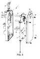
- Figure 1shows an exploded view of a heating device of a liquid food or beverage preparation machine, in which liquid is circulated through a thermoblock and then guided into a brewing chamber for brewing a food or beverage ingredient supplied into the brewing chamber.
- a beverage ingredientis supplied to the machine in prepackaged form, for example contained in a capsule or in a pod.
- this type of liquid food or beverage machineis suitable to prepare coffee, tea and/or other hot beverages or even soups and like food preparations.
- the pressure of the liquid circulated to the brewing chambermay for instance reach about 10 to 20 atm.
- the heating deviceincorporates a thermoblock and a printed circuit board according to the invention.
- Figures 2 and 3show further details of the printed circuited board 4 in its housing 3 of the heating device of Fig. 1 .
- thermoblockwith an aluminium metal mass 1 and a functional block 2 including a thermal and electrically insulating plastic housing 3 containing a printed circuit board 4.
- Metal mass 1incorporates a water inlet, a water outlet and a water heating duct extending therebetween to form a rigid free-flow passage (not shown) for guiding water circulating from a water reservoir via a pump through metal mass 1.
- the heating ductmay comprise an upper flow portion followed by a down-coming flow portion, for example portions of a generally helical duct which extends along a horizontal or non-vertical inclined axis.
- Such upper flow and down-coming flow portionsmay have a narrowed cross-section for promoting an increased velocity of water therealong to inhibit an accumulation of bubbles in such upper flow portion by pushing them down the down-coming flow portion by the flow of water with increased velocity.
- the ductis arranged so that the size of its cross-section changes along the chamber, to increase the flow velocity in areas, usually upper areas, which might otherwise serve to capture bubbles, in particular vapour bubbles.
- the heating powermay be reduced on the corresponding parts of the heater, for instance, by adjusting the resistive means on these parts.
- this ducthas a reduced cross-section along its entire length to provide a sufficient velocity of the water flow for flushing possible vapour bubbles formed therein during heating.
- Metal mass 1 of thermoblockfurther includes an opening 1b which forms or rigidly anchors an upstream part of the brewing chamber (not shown) so that the rigid passage of metal mass 1 extends into the brewing chamber.
- the liquid food or beverage preparation machinealso comprises a downstream part (not shown) having a liquid food or beverage outlet and cooperating with the upstream part to form the brewing chamber, the downstream part and the upstream part can be movable apart and movable together for the supply into the brewing chamber and the evacuation from the brewing chamber of the ingredient.
- the upstream part of the brewing chamber integrated into the thermoblockwill be fixed in the liquid food or beverage preparation machine and the downstream part of the brewing chamber will be movable.
- the brewing chambermay have a generally horizontal orientation, i.e. such a configuration and orientation that the water flows through the food or beverage ingredient in the brewing chamber along a generally horizontal direction, and the upstream part and/or downstream part may be movable in the same or in the opposite direction of the water flow in the chamber.
- Embodiments of such a thermoblock and brewing chamberare for example disclosed in EP 07117853.7 (NO8405), the content of which is hereby incorporated by way of reference.
- Functional block 2is secured to metal mass 1 via snaps 3a of housing 3 that cooperate with corresponding recesses 1a in the surface of metal mass 1 when housing 3 is assembled to metal mass 1 in the direction of arrow 3'.
- the two part housing 3 of functional block 2encloses printed circuit board 4 on all sides, in particular in a substantially impervious manner so as to protect board 4 against liquid and vapours in the machine.
- the two parts of housing 3may be assembled by screws 3b or any other appropriate assembly means, such as rivets, gluing, welding, etc.
- Functional block 2includes a user interface with a master switch 2a and two control switches 2b that are connected via housing 3 to printed circuit board 4. It is of course possible to use more elaborated user interfaces including screens or touch screens.
- Printed circuit board 4includes power connectors 80 for supplying electric heating power to metal mass 1 via power pins 11 extending through corresponding openings in housing 3, further electrical connectors 4a for one or more further electric devices in the liquid food or beverage preparation machine, such as a user interface, pump, fan, valve, liquid cooling element, etc... as required, and a connector 4b to the mains for the central electric power supply.
- thermoblockincludes electric components, namely a temperature sensor 70 connected to plug member 52, thermal fuses 75, a power switch in the form of a triac 60 in a cavity the opening of which is formed between protruding walls 102 and a heating resistor (not shown) with connector pins 11, that are rigidly secured into metal mass 1 and rigidly connected to printed circuit board 4, as will be explained in greater details below in connection with Figures 5 to 12b .
- printed circuit board 4is electrically connected via a rigid connector or cable 91 to a hall sensor 90 of a flow meter that is located on the water circuit of the beverage preparation machine, typically between a pump and a water or other liquid source such as a water or liquid reservoir, or between a pump and a heating device, or within the heating device.
- printed circuit board 4may carry a micro-controller or processor and possibly a quartz clock for controlling the intensity of current passed to resistive heating element based on the flow rate of the circulating water measured with the flow meter and the temperature of the heated water measured with the temperature sensor.
- one or more temperature sensorsmay be incorporated into metal mass 1 and/or into the brewing chamber and/or upstream the metal mass 1 or at its water inlet.
- the controller or processormay also control further functions of the liquid food or beverage preparation machine, such as a pump, a liquid level detector in a water supply reservoir, a valve, a user interface, a power management arrangement, an automatic beverage ingredient supplier such as an integrated coffee grinder or an automatic supplier of ingredient capsules or pods, etc...
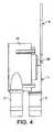
- FIG. 4illustrates another embodiment according to the invention of a flow meter 95 for a liquid food or beverage preparation machine according to the invention.
- Flow meter 95includes a hall sensor 90' that is incorporated onto printed circuit board 4 as an integrated component of the printed circuit board 4 or as a discrete component rigidly mounted or connected thereto, typically by welding.
- Flow meter 95is also integrated in the water circulation circuit 5 and is connected to a water incoming pipe 5' and a water outgoing pipe 5" and to the printed circuit board 4 via hall sensor 90'.
- Water pipes 5',5"may be flexible, e.g. made of silicon, or rigid to facilitate automatic assembly.
- Flow meter 95includes a internal magnetic helix or rotor (not shown) through which water is circulated.
- the water flowdrives within flow meter 95 the magnetic helix or rotor in rotation at an angular speed that is proportional to the velocity of the flow of water thereby causing a corresponding rotation of the magnetic field generated by the magnetic helix or rotor, which is detected by hall sensor 90' and converted into a corresponding electric signal on printed circuit board 4.
- the corresponding manufacturing steps of the liquid food or beverage preparation machinedo not require human intervention, less components, in particular no separate connector link, in particular no electric cable, and thus reduces the production costs of the assembly of the liquid food or beverage preparation machine as well as its reliability since fewer parts are involved and the human factor is also reduced.
- a liquid to be heatedis circulated, for instance by using a pump, via flow meter 90,90',91,95 and then freely through the inlet of metal mass 1, through the heating duct and through the outlet of mass 1 into brewing chamber for brewing the ingredient contained therein.
- the controller on printed circuit board 4is arranged to control triac 60 for adjusting the heating current passed via power pins 11 to heating resistor in metal mass 1, based on measures of the liquid flow by means of flow-meter 90,90',91,95 and of the temperature of the heated liquid by means of temperature sensor 70 connected to plug member 52.
- Figures 5 and 6in which the same numeric references designate then same elements, illustrate in greater detail the rigid assembly of a discrete power component in the form of a triac 60 to metal mass 1 and to a printed circuit board 4 according to the invention. Whereas Figure 5 shows the assembly in an exploded perspective view, Figure 6 discloses the assembly in cross-section.
- Metal mass 1a part of which is shown in Figures 5 and 6 , has a recess 101 for receiving power component 60.
- Recess 101the opening of which is formed between protruding walls 102, is associated with a spring element 103, for example in the shape of a spring leaf, assembled to metal mass 1, e.g. via a screw 104.
- spring element 103urges power component 60 against walls 102 of recess 101 in metal mass 1 when component 60 is inserted into recess 101, to secure component 60 in mass 1 and provide an optimal contact between mass 1 and component 60.
- Power component 60has one or more rigid electrical connector pins 61, for instance three pins for the triac shown in Figures 5 and 6 , which are rigidly connected to printed circuit board 4. Furthermore, power component 60 is covered with an optional cap 62, e.g. made of silicon, that may assist fixation of the power component 60 in recess 101, as well as an optional non conductive sleeve 63 around its connector pins 61 which spaces the main body of power component 60 from printed circuit board 4 and protect pins 61 against the environment. Moreover, cap 62 and sleeve 63 provide an electric insulation around power component 60.
- cap 62 and sleeve 63provide an electric insulation around power component 60.
- metal mass 1serves as a heat sinker for power component 60 by evacuating, via mass 1 and optionally via the water circulating through mass 1, heat generated by the power component during use.
- mass 1is configured and made of a metal, such as aluminium or steel, that allows optimal evacuation of heat from the power component along the heat evacuation path through mass 1.
- Power component 60may be a switch or regulating element, e.g. a triac as mentioned above, for adjusting the required electric power that is supplied to the resistive means, e.g. a heating resistor, for generating the desired heat in metal mass 1 in order to heat the circulating water to the appropriate temperature.
- the resistive meanse.g. a heating resistor
- FIGS 7 to 9illustrate the rigid assembly of a discrete electronic component 70 into metal mass 1 and to a printed circuit board 4.
- This electronic componentmay be a sensor such as a temperature sensor, a flow meter, a thermal fuse or another similar component, such as an ammeter for providing a feedback of the current passed through the resistive heating means, e.g. heating resistor.
- a thermal sensor 70for the control of heating electric current passed to the heating resistor via pins 11 and adjustment of the heat generated in metal mass 1 is disclosed.
- Thermal sensor 70may for example be located at the inlet or outlet of metal mass 1 or thereinbetween. Several thermal sensors may be used to allow a more precise control of the heating of the water passed via metal mass 1.
- Metal mass 1a part or which is shown in Figures 7 to 9 , has a recess 111 for receiving the electronic component 70.
- Recess 111is formed between protruding walls 112 and extends below the surface of metal mass 1.
- Sensor 70has a connector socket 71 through which a sensor element 72 is joined to electric flat connectors 73 on the opposite side of socket 71.
- the sensor's connection pins 73are brought into contact with flat connector pins 51, one of which is shown in Figure 8 , of printed circuit board 4.
- Pins 51extend through a plug member 52 of board 4 into socket 71 for contacting the corresponding connection pins 73 of sensor 70.
- plug member 52extends through housing 3 via a corresponding opening.
- plug member 52may be integral with housing 3 and electrically connected to printed circuit board 4.
- sensor 70When sensor 70 is a temperature sensor, the electric characteristics of sensor element 72 will depend on the temperature in recess 111, which will be used for evaluating the temperature of metal mass 1 at this location and optionally also the temperature of water circulating in metal mass 1 in an indirect evaluation process.
- Sensor element 72may for instance be an NTC (negative temperature coefficient) resistor or a PTC (positive temperature coefficient) resistor.
- Such a sensor configurationpermits reliably measuring the temperature in the corresponding location of the heater, fast reaction (low inertia) and provides an excellent and reliable electric contact system.
- Sensor 70may be preassembled into socket 71, for instance made of thermoplastic material, and assembled into metal mass 1 and to printed circuit board 4 in a fully automatic process. Sensor 70 may be glued into metal mass 1 using for example an epoxy compound. The preassembled sensor 70 may then be connected by pressing the socket's flat connectors 73 into connection slots of socket 71 in such a way as to be connected to sensor element 72. Printed circuit board 4 is then mounted with housing 3 onto socket 70 via plug 52 and connector pins 51.
- thermoblock with metal mass 1 and printed circuit board 4does not require handling any flexible parts and thus the assembly can be carried out automatically without the need of any human intervention. Furthermore, the assembly of sensor 70 itself only requires low cost components. Hence, the assembly of sensor 70 on metal mass 1 and its connection to printed circuit board 4 leads to significant cost savings.
- Figure 10is a perspective view in an xyz orthogonal referential, as indicated by the corresponding arrows associated with Figures 10 to 12b , of a self-positioning rigid electric power connector 80 for connecting a heating resistor to a printed circuit board 4 and for carrying electric heating current thereto or therefrom.
- Power connector 80is typically metal-based, and may in particular contain steel, aluminium and/or copper alloys that provide sufficient electric conductivity, mechanical resistance and resilience.
- Power connector 80extends between a pair of flat feet 81 for connection to a printed circuit board 4.
- Each foot 81is connected to a bottom part of a flat generally upright spring member 82.
- the upper parts of the upright spring blades 82are connected together via a transverse spring member 83 that comprises a flat central horizontal part 84 inbetween a pair of inclined intermediate parts 85,85'.
- Upright members 82, intermediate part 84 and inclined parts 85,85' of transverse member 83are in a general M arrangement on the pair of feet 81.
- Transverse member 83further includes a socket 86 with a through-passage for securing therethrough an electric connector pin 11 extending from metal mass 1.
- a power connector 80is schematically shown assembled via a power pin 11 to a heating resistor (not shown) in metal mass 1.
- Power pin 11extends upright from the surface of metal mass 11 and is secured in the through-passage of socket 86 of transverse member 83.
- housing 3as shown in Figures 1 to 3 , extending between printed circuit board 4 and metal mass 1, is not shown in Figures 11a to 12b .
- Feet 81 of power connector 80are electrically connected and secured onto printed circuit board 4, for instance by rivets or welding 81' or any other suitable assembly means.
- Metal mass 1faces printed circuit board 4 so that power pin 11 extends through corresponding holes in housing 3 and through board 4 via a through-opening 55 in board 4 to the other side of board 4 and is then secured in through-passage 86 of power connector 80.
- Continuous electrical connection between power pin 11 and transverse member 83may be achieved by force-fitting or welding pin 11 in through-passage 86.
- Power connector 80allows for small positioning displacements of through-passage 86 in the x direction and y direction, with reference to the xyz referential associated with Figs. 10 to 12b .
- Different directions of displacementsare provided by the different orientations, in particular perpendicular orientations, of the resilient spring blade members 82,83, which permit displacements along corresponding directions.
- Figures 11a and 11bon the one hand, and Figures 12a and 12b , on the other hand, show a displacement of the connector's socket 86 assembled to power pin 11 along the y direction and the x direction respectively. Displacement of socket 86 in the x and y directions is achieved by a small flexion of upright spring blades 82 and a small flexion of inclined intermediate parts 85,85', respectively.
- Figures 11a and 12ashow power pin 11 extending right through the middle of through-opening 55, and through the through-passage of socket 86 which all extend along substantially the same axis.
- power pin 11is positioned in line with power connector 80 which is thus not subjected to any displacement flexion stress in its upright spring blades 82 and inclined intermediate parts 85,85'.
- FIGs 11b and 12bshow power pin 11 extending eccentrically through through-opening 55.
- Through-passage of socket 86 aligned to power pin 11is equally eccentric with respect to through-opening 55.
- printed circuit board 4is not perfectly aligned with power pin 11 of the heater and power connector 80 self-adapts the position of its through-passage in socket 86 to match precisely the position of pin 11 by flexion of its upright spring blades 82 in the x direction, as shown in Figure 12b , or by flexion of its transverse spring member 83 in the y direction, as shown in Figure 11b .
- the lower part 86' of socket 86has a generally funnel-like or frustoconical shape that is arranged to receive a generally conical upper end of power pin 11.
- the displacement of socket 86 to adapt to the position of power pin 11may result from discrepancies, e.g. manufacturing tolerance or different temperature-related dilatation mechanisms, between the relative positioning of a pair of power connectors 80 on printed circuit board 4 with respect to the relative positioning of a corresponding pair of power pins 11 on the metal mass.
- discrepanciese.g. manufacturing tolerance or different temperature-related dilatation mechanisms
- the relative position of other electrical components that are rigidly connected to the printed circuit board and fixed parts of the beverage preparation machine, in particular the metal massfor example temperature sensors and power regulator or switches, e.g. like the ones shown in Figures 5 to 9 , may induce displacements at the level of the power connection.
- first power connector 80the passage of current from and back to printed circuit board 4 via first power connector 80, first power pin 11, the heating resistor (not shown) in metal mass 1, the second power pin 11, the second power connector 80, is controlled by a power switch or regulator, e.g. a triac 60, for instance as illustrated in Figures 5 and 6 .
- a power switch or regulatore.g. a triac 60, for instance as illustrated in Figures 5 and 6 .
- Figures 11a and 11balso illustrate how an error of relative positioning of feet 81 and inclined parts 85,85' on printed circuit board 4 is managed by power connector 80.
- feet 81 and thus inclined parts 85,85'are not perfectly aligned in the x direction but slightly off-set one to another. This off-set is however fully compensated by a corresponding resilient deflection of transverse member 83 without causing excessive stress in printed circuit board 4 or in power connector 80.
- the spacing between the two anchorage locations on printed circuit board 4 for anchoring feet 81are greater or shorter than the spacing between feet 81 when the power connector is in a relaxed state, then a corresponding resilient deflection of members 82 can absorb such a spacing difference without excessive or detrimental stress in power connector 80 or printed circuit board 4.
- Figure 13illustrates a variation of the heating device in accordance with the invention which includes a flex-print 4' instead of a printed circuit board.
- Flex-print 4'is bonded, in particular glued, to the surface of a metal mass 1 of a thermoblock.
- Flex-print 4'has: an inner side applied to metal mass 1 that incorporates a resistor heater in the form of a heating foil or film.
- the outer side of flex-print 4'carries one or more electric components 60,75' that are rigidly secured to the outer slide.
- Flex-print 4'may also incorporate on its inner side one or more electric components.
- the electric componentsmay be integrated components or discrete components, such as resistor heaters, sensors and/or power switches, e.g. triacs, that are secured into and/or onto to the metal mass, and/or one or more components on the outer side of the flex-print, for example a controller.
- flex-print 4'is rigidly connected to a thermal fuse 75' and to a triac 60. Since the inner surface of flex-print 4' matches the surface of metal mass 1, triac 60 on the outer surface of flex-print 4' is in thermal communication with metal mass 1 via flex-print 4' so that heat generated by triac 60 during use can be well evacuated via metal mass 1 and optionally via the water circulating in mass 1.
- a triac and/or other electric components, such as thermal sensorsmay be rigidly connected to the inner side of flex-print to improve thermal communication between the triac and the metal mass.
- Flex-print 4'is connected to functional block 2 into housing 3 via arm 4" for data and power connection. Via arm 4" flex-print 4' may be connected to a printed circuit board, for instance in housing 3, and/or to further electric devices, such as a user interface or a main switch 2a.
- the thermoblock with its metal mass 1is also rigidly connected to functional block 2, for instance by means of snaps, screws, rivets, etc...
- FIGS 14 and 15in which the same numeric references designate generally the same elements, schematically disclose two alternative embodiments of a beverage or liquid food machine with a user-reversible fuse device. !
- the machine according to the inventionhas an electric supply circuit 57 that is connectable to a power source (not shown), such as the mains or an equivalent power source.
- Supply circuit 57is connected to a printed circuit board (PCB) 4 which bears the machine's control unit, e.g. a micro-controller, memory device, various interfaces to the various parts of the machine that require automatic control, such as a user-interface, a pump, a heater 1, sensors 60,70, etc...
- Supply circuit 57has a main switch 205,205' allowing a user to switch on and off the beverage or liquid food machine.
- In-line heater 1has a water inlet 1' connected to a water source, in particular via a pump (not shown), and a downstream cavity 1b delimiting an upper part of a brewing unit arranged to receive a pre-packaged beverage ingredient such as a coffee or tea capsule and to cooperate with a beverage or liquid food outlet member or assembly (not shown).
- main switch 205,205'is mechanically mounted onto PCB 4 to facilitate assembly and increase integration of the system.
- the machineincludes a thermal fuse device 200 that has a switch 205 on circuit 57 and an actuator 201,201' arranged to disconnect circuit 57 by actuating switch 205 when heater 1 has a temperature that exceeds a temperature limit, e.g. a temperature limit in the range of 120°C to 180°C, in particular 140°C to 160°C, indicative of a malfunction of heater 1 or of its control unit 4.
- a temperature limite.g. a temperature limit in the range of 120°C to 180°C, in particular 140°C to 160°C, indicative of a malfunction of heater 1 or of its control unit 4.
- Thermal fuse device 200is user reversible. Upon safety disconnection of circuit 57 by fuse device 200, switch 205 may be operated by a user to reconnect circuit 57 and re-establish electric powering of PCB 4. Hence, if thermal fuse device 200 goes off improperly or if heater 1 merely has an accidental one time overheat condition, the liquid food or beverage machine of the invention does not need to be returned for servicing in order to replace the fuse device, unlike existing beverage or liquid food machines fitted with one-time thermal fuses.
- Fuse device 200has an actuator 201,201' that is arranged to push out a pin, rod or piston 202 against the user switch, e.g. a switch of the push-button type, when said temperature limit is exceeded by the heater so as to actuate the user switch and open circuit 57.
- the user switche.g. a switch of the push-button type
- the embodiment show in Fig. 14has a fuse device 200 with an actuator 201 including a pin 202 movable along the direction of arrow 202' and a thermo-mechanical component mounted onto heater 1 and in thermal communication therewith.
- the thermo-mechanical componentmay be any arrangement suitable to convert the passage of a temperature level into a mechanical action or displacement, such as an element made of a shape memory alloy that remembers its shape, or a bi-metallic strip element.
- thermo-mechanical component of actuator 201when heater 1 exceeds the temperature limit, the thermo-mechanical component of actuator 201 is activated and will urge pin 202 against user switch 205. This will disconnect the electric parts of the machine from the power supply connected to circuit 57.
- the thermo-mechanical componentWhen the heater's temperature drops below the temperature limit, the thermo-mechanical component will return back into its normal state and pin 202 will either follow the thermo-mechanical component or may be pushed back into its normal position by a user who actuates switch 205 to re-establish the power connection of the machine.
- the user switch 205 cooperating with the thermal fusemay also serve as a main switch that may be operated independently of any over-heat situation in order to ordinarily switch on and off the beverage or liquid food machine.
- the user switch 205 cooperating with the thermal fuseis a dedicated switch separate from the main switch 205'.
- Fuse device 200comprises a safety electric temperature sensor 203 mechanically mounted against heater 1 and in thermal communication therewith. Furthermore, to simplify assembly and further integrate the electric components of the machine, temperature sensor 203 is rigidly connected to PCB 50 in a similar manner as discussed above. In a less preferred embodiment, such a temperature sensor may also be connected by other means to the PCB, in particular in a partly or entirely flexible manner.
- Temperature sensor 203monitors the temperature of heater 1. Temperature sensor 203 is associated with a control means that controls the electrical powering of actuator 201' via its connection circuit 204 depending on the measured temperature.
- the control meansincludes a power switch, e.g. a transistor, on connection circuit 204 connected to temperature sensor 203.
- the temperature sensor 203, the power switch associated therewith, user switches 205 and even actuator 201'are rigidly mounted onto PCB 4.
- these componentsare mounted on a section 41 of PCB 4 that is electrically insulated from the ordinary control unit of the beverage and liquid food machine on PCB 4.
Landscapes
- Engineering & Computer Science (AREA)
- Food Science & Technology (AREA)
- Physics & Mathematics (AREA)
- Thermal Sciences (AREA)
- Microelectronics & Electronic Packaging (AREA)
- Chemical & Material Sciences (AREA)
- Combustion & Propulsion (AREA)
- Mechanical Engineering (AREA)
- General Engineering & Computer Science (AREA)
- Manufacturing & Machinery (AREA)
- Apparatus For Making Beverages (AREA)
- Cookers (AREA)
- Devices For Dispensing Beverages (AREA)
- Control Of Resistance Heating (AREA)
Abstract
Description
- The present invention concerns a heating device with an integrated thermoblock for the heating of a liquid in a liquid food or a beverage preparation machine.
- Liquid food and beverage preparation machines have been known for a number of years.
- For instance,
US 5,836,236 discloses a coffee brewer and hot water dispenser having a brew water tank with a preheater and a brew boiler for boiling preheated water and a hot water tank with a hot water heater. The tanks are heated in sequence, only one heater being energized at a time. The various heaters are connected to an electronic controller for regulating the brew water, level and temperature is located underneath the tank and protected by a thermoplastic shield. The heaters are made of an electric resistance wire and are associated with a safety switch. The electronic interconnection within the brewer is achieved by a ribbon cable having individual wires bearing terminal connectors.US 2007/0044664 discloses an automatic coffee machine having a boiler into which cold water is pumped and then heated for brewing coffee. Connections boiler's heater, sensors, flow meter, pump to a control circuit are schematically disclosed. The boiler includes a pair of thermal fuses to cut off the heater in case of overheating.WO01/60221 - Different fields of technology may use heaters, flow meters and thermal sensors and fuses, e.g. to dispense a viscous fluid namely body lotion, as disclosed in
WO 99/51947 US 5,943,472 discloses a water circulation system between a water reservoir and a hot water or vapour distribution chamber of an espresso machine. The circulation system includes a valve, metallic heating tube and pump that are connected together and to the reservoir via different silicone hoses, which are joined using clamping collars.EP 1 646 305- In-line heaters for heating circulating liquid, in particular water are also well known and are for example disclosed in
CH 593 044 DE 103 22 034 ,DE 197 32 414 ,DE 197 37 694 ,EP 0 485 211 ,FR 2 799 630US 4,242,568 ,US 4,595,131 ,US 5,019,690 ,US 5,392,694 ,US 5,943,472 ,US 6,393,967 ,US 6,889,598 ,US 7,286,752 ,WO 01/54551 US 2003/0066431 andWO 2004/006742 . - More particularly,
CH 593 044 US 4,242,568 disclose a coffee machine with an inline thermoblock heater having a metal mass with resistive heating cable cast in the mass and with a duct for the circulation of water to be heated. EP 0 485 211 discloses a heater for a water heater, shower, washing machine, dishwasher or kettle. The heater includes a vessel for heating liquid, and an electric heating element which is arranged to heat a portion of the vessel. The heating element incorporates a thick-film resistive heating circuit with a thermal fuse included in the thick-film. The document further discloses a triac-type power regulator mounted directly on the heating element that acts as a heat sinker for this triac. Also disclosed is the presence of a thermistor, a temperature sensor, formed on the thick film, a thermal fuse, a flow control valve to continuously adjust the flow rate through the heater, a flow control and a temperature control. These electrical components are connected to a control unit that can be remote or formed as part of the dielectric layer of the thick film at a location close to the inlet pipe where the heater's metal substrate is kept cool by incoming cold water. Similar ideas are disclosed inDE 103 22 034DE 197 32 414 andDE 197 37 694 . Inline tubular heaters for beverage preparation devices are disclosed inWO 01/54551 WO 2004/006742 andUS 7,286,752 .US 6,889,598 discloses a beverage device containing a liquid and having an operating apparatus for heating, cooling, agitating, whipping, pumping or frothing the liquid or grinding an ingredient, the operating apparatus being powered via an electronic switch such as a triac that is cooled by being in heat passing relationship with the liquid so as to evacuate the heat produced by the switch to the liquid, in particular via the bottom of a liquid heating tank made of steel or aluminium, and optionally with a radiator.- Moreover,
US 5,019,690 discloses a boiling water dispenser that has a resistive heater powered via a triac switch connected via cables to a control module and mounted on the bottom of the dispenser's water reservoir to evacuate heat generated at the triac switch via the water. US 4,595,131 discloses a beverage preparation machine with a water heating reservoir that is electrically connected to a printed circuit board via a series of cables leading to a thermostatically controlled heater and a thermistor probe in the reservoir.EP 1 610 596FR 2 799 630EP 0 387 515 discloses an aircraft coffee maker having a fluid circuit connectable to an external water supply via a rear water supply connector. The fluid circuit includes the water supply connector, a rear inline heater and a top coffee brew nozzle that are in fluid communication via flexible tubing. The heater has three successive heater tubes, each with a central and elongated heating element, and inlet and outlet flared connectors for connecting the flexible tubing thereon. The heater further includes a first temperature sensor, a backup temperature sensor and a water sensor. The heating elements and sensors are all electrically connected via wires. The machine further includes an upper front user-interface with a printed circuit board with a number of wires and an electronic box with a heat sinker at the back of the machine.US 2003/0066431 discloses a coffee machine with a fluid circuit made of several tubularly inter-connected fluid modules including a water reservoir followed by a pump and then an in-line heater, water delivered by the heater is passed via a connection tube to a separate diverter and thereafter into a pod brewing unit. The inline heater is made of a heating tube inbetween a pair of cast aluminium bars, each bar containing a discrete heating resistor. A thermal cut-off, i.e. a one-time fusible link, and a thermistor, i.e. a thermal sensor, are clipped on the aluminium bars. The heating tube, the bars with the heating resistors, the thermal cut-off and the thermistor are enclosed within a heater housing through which water inlet and outlet fittings extend for connecting the heating tube into the fluid circuit of the coffee machine. The coffee machine further comprises a controller that appears to be mechanically assembled the housing of the heater by what seems to be a prismatic member. This controller is said to be "operably connected" various parts of the beverage machine, namely to the buttons, pump motor, pump sensor, heating resistor, thermal cut-off, thermistor, actuator sensor, pod sensor, reservoir sensor, diverter sensor, etc...- A preferred object of the present invention is to simplify and improve the incorporation of the heating function in a liquid food or beverage preparation machine to facilitate and permit an increased automation of the assembly of the machine, reduce the manufacturing operations and costs and increase the reliability of the machine.
- This object is in particular achieved by providing a heating device that integrates electrical and optionally fluid connections without requiring any flexible and deformable cable or tubes, for guiding current or liquid, to connect the heating function to other functional units of the liquid food or beverage preparation machine, or at least to limit the number of such flexible and deformable connections.
- Therefore, the present invention relates to an inline heating device for a liquid food or beverage preparation machine. In such a machine, liquid is circulated, for instance from a liquid reservoir via a pump, through this heating device. Typically, the liquid that is circulated through the heating device is water. From the heating device, the heated liquid is guided into a machine's brewing chamber in which an ingredient may be brewed. The brewing chamber may include a capsule or pod housing, e.g. receiver, for housing an ingredient supplied within a capsule or pod into the brewing chamber.
- For instance, the brewing chamber is arranged to contain a food or beverage ingredient, such as powder soup, ground coffee or tea optionally in a capsule or a pod. The brewing chamber may have an upstream part into which hot liquid is injected for brewing the food or beverage ingredient contained in the chamber and a downstream part leading into an outlet for guiding the liquid food or beverage produced by brewing.
- Thermoblocks are typically in-line heaters through which a liquid is circulated for heating. They comprise a heating chamber, such as one or more ducts, in particular made of steel, extending through a (massive) mass of metal, in particular made of aluminium, iron and/or another metal or an alloy, that has a high thermal capacity for accumulating heat energy and a high thermal conductivity for the transfer the required amount of the accumulated heat to liquid circulating therethrough whenever needed. Instead of a distinct duct, the thermoblock's duct may by a through passage that is machined or otherwise formed in the duct's body, e.g. formed during a casting step of the thermoblock's mass. When the thermoblock's mass is made of aluminium, it is preferred, for health considerations, to provide a separate duct, for example of steel, to avoid contact between circulating liquid and aluminium. The block's mass can be made of one or several assembled parts around the duct. Thermoblocks usually include one or more resistive heating elements, for instance discrete or integrated resistors, that convert electrical energy into heating energy. Such resistive heating elements are typically in or on the thermoblock's mass at a distance of more than 1 mm, in particular 2 to 50 mm or 5 to 30 mm, from the duct. The heat is supplied to the thermoblock's mass and via the mass to the circulating liquid. The heating elements may be cast or loused into the metal mass or fixed against the surface of the metal mass. The duct(s) may have a helicoidal or another arrangement along the thermoblock to maximise its/their length and heat transfer through the
- The heating device of the invention comprises: a thermoblock with a metal mass that incorporates an inlet, an outlet and a heating chamber extending therebetween, the mass being arranged to accumulate heat and to supply heat to the liquid; and one or more electric components that are rigidly secured onto or into the thermoblock and that are connected to a printed circuit board (PCB) and/or a flex-print arranged to control such thermoblock and optionally further functions of the liquid food or beverage preparation machine. Such electric components may include sensors, thermal fuses and/or electric power components, in particular temperature sensors, flow meters, resistor heaters, ammeters and electric power regulators.
- In accordance with the invention, one or more of these electric components are rigidly connected to the printed circuit board and/or flex-print (or flexible circuit), in particular via rigid connector pins or blades or rigid plug and socket members.
- To reduce the number of assembly operations, in particular human interventions during the manufacturing process, the number of flexible, deformable, electric cable connections are reduced. In particular, the electric components can be rigidly connected to this printed circuit board or flex-print, for instance via rigid connector pins or blades or rigid plug and socket members. Possibly, the electric components are present the form of in integrated components on a printed circuit board or flex-print that is secured to the thermoblock and comes with these electric components into contact with the thermoblock's metal mass. In such a way, the electric components, in particular those which come into contact with the liquid circulation system such as the heating resistor(s), can be mounted automatically on the printed circuit board or the flex-print, and then the board or flex-print with its electric components is assembled (for instance clipped or glued) automatically onto the liquid circulation system without using any flexible, deformable electric connectors (e.g. cables) between the board or flex-print and the liquid circulation system. Alternatively, the electric components may be automatically mounted in a first step at dedicated locations of the liquid circulation system and then, in a second step, the printed circuit board or flex-print is assembled, for instance via an appropriate connector, to the electric components. It is also possible to assemble by welding the electric components to the liquid circulation system, in particular to the thermoblock and/or to the printed circuit board or flex-print. As mentioned, it is possible to provide some of these electric components as integrated components in the printed circuit board or flex-print, such as a heating resistive film formed on the surface of a printed circuit board or flex-print and applied directly against the surface of the thermoblock's metal mass.
- In one embodiment, such an electric component is secured in a cavity of the thermoblock's metal mass. Optionally, the component is secured in the cavity by means of a biased spring element in the cavity or the cavity forms a socket for a plug comprising the component. Electric components may also be cast into the metal mass or glued into or onto the metal mass, or attached by any other suitable means together with the metal mass, e.g. screwing, force fitting, welding, etc...
- Such electric component may include a power component, such as a resistor heater and/or a power switch, which is rigidly connected via a rigid electric power pin and a rigid power connector that has a socket for receiving the rigid electric pin. The rigid connector can be resilient, in particular made of one or more spring blades, to allow small displacements of the socket for self-positioning the socket around the pin and to secure electric contact between the pin and the connector.
- The printed circuit board may be contained in a thermal and electric insulating housing, such as a plastic housing, that is mechanically connected to the thermoblock, in particular via snaps. Preferably, the housing is substantially impervious to protect the board against liquids and vapours in the machine. The printed circuit board may have one or more openings for the passage of the electrical connectors for connecting to the printed circuit board such electric components that are rigidly secured on or in the metal mass.
- The flex-print may be secured, typically glued, to a surface of the thermoblock, in particular to its metal mass. The flex-print can have: an inner side that faces the thermoblock or metal mass and that incorporates a resistor heater in the form of a heating foil or film; and an outer side to which one or more electric components are optionally rigidly secured. Alternatively, the flex-print may incorporate on the inner side one or more electric components, in particular discrete components, such as resistor heaters, sensors and/or power switches, e.g. triacs, that are rigidly secured into and/or onto to the metal mass, and/or one or more components on the other side of the flex-print, for example a controller, a clock element and an interface connector for other electric devices of the liquid food or beverage preparation machines, such as a pump, electro-valve, user interface, level detector in a liquid reservoir or used ingredient collector, etc...
- The electric components may be discrete components and/or integrated components, for instance formed directly into the flex-print and secured with the flex-print directly onto the thermoblock or its metal mass. Typically, thermal fuses, heating resistors and temperature sensors may be formed in flex-print technology.
- Generally speaking, the printed circuit board as well as the flex-print can be arranged to control the thermoblock and optionally further functions in a liquid food or beverage preparation machine, of the type mentioned above by way of example.
- The heating chamber in the metal mass is usually elongated, e.g. forms a duct, along a direction of flow of liquid through the mass. The heating chamber may comprise an upper flow portion followed by a down-coming flow portion, for example portions of a generally helical duct which extend helically along horizontal or non-vertical inclined axis. Such upper low and down-coming flow portions may have a narrowed cross-section for promoting an increased velocity of liquid therealong to inhibit an accumulation of bubbles in such an upper flow portion by pushing them down the down-coming flow portion by the flow of liquid with increased velocity. In this configuration, the elongated chamber is arranged so that the size of its cross-section changes along the chamber, to increase the flow velocity in areas, usually upper areas, which might otherwise serve to capture bubbles, in particular vapour bubbles. The increased liquid velocity in these areas "washes" the bubbles down and away from these areas with the fast flow of liquid in these areas. To avoid overheating in such areas with reduced cross-section, the heating power may be reduced on the corresponding parts of the heater, for instance, by adjusting the resistive means on these parts.
- Another aspect of the invention relates to a liquid food or beverage preparation machine. This machine comprises: a brewing chamber for brewing a food or beverage ingredient by circulating heated liquid therethrough; and an in-line heating device with a thermoblock having a metal mass, as described above, for heating and supplying circulating liquid to the brewing chamber. The brewing chamber may be a capsule or pod housing for receiving an ingredient supplied within a capsule or pod into the brewing chamber.
- Typically, the metal mass' inlet, outlet and heating chamber form together a rigid passage, in particular a rigid free-flow passage, for guiding the liquid circulating through the mass.
- The thermoblock itself may incorporate an upstream part of the brewing chamber, the upstream part being formed by or rigidly anchored in the metal mass so that the rigid passage, in particular the rigid free-flow passage, of the metal mass extends into the brewing chamber. Furthermore, the machine usually includes a downstream part having a liquid food or beverage outlet and cooperating with the upstream part to form the brewing chamber. The downstream part and the upstream part may be movable apart and movable together for the supply into the brewing chamber and the evacuation from the brewing chamber of said ingredient. For instance, the upstream part and the metal mass are fixed, the downstream part being movable to and from the upstream part. Alternatively, the upstream part and the metal mass can be movable en bloc to and from the downstream part, the downstream part being fixed or movable in said machine.
- Hence, the heating device of the invention may be used in connection with brewing chambers of the type disclosed in
EP 1 646 305EP 07117853.7 - A further aspect of the invention relates to a liquid food of beverage preparation machine, in particular as described above. The machine comprises: an electric supply circuit connectable to an electric power source; a heater powered by the electric supply circuit; and a thermal fuse device in thermal communication with the heater and associated with the electric supply circuit. The fuse device is arranged to interrupt the electric supply circuit from the power source when the heater exceeds a temperature limit.
- In accordance with the invention, the thermal fuse device is reversible and comprises a switch for automatically interrupting the electric supply circuit when the heater exceeds this temperature limit. The switch is operable by a user to close the electric supply circuit when the heater has a temperature that has returned below said temperature limit. Typically, the fuse device comprises an actuator that is arranged to push out a pin, rod or piston against the user switch when this temperature limit is exceeded by the heater so as to actuate the user switch and open the circuit.
- This beverage or liquid food machine may include any of the above disclosed features or combination of features.
- The fuse device may have an actuator which comprises a thermo-mechanical component that is in thermal communication with the heater and that mechanically actuates the user switch to open the electric supply circuit when the heater exceeds the temperature limit. The thermo mechanical component comprises in particular a shape memory element or a bimetal element.
- The fuse device can include a safety electric temperature sensor in thermal communication with the heater and an electromechanical actuator that actuates the user switch to open the electric supply circuit when the safety sensor is exposed to a temperature generated by the heater which exceeds the temperature limit.
- In one embodiment, the beverage or liquid food machine has a printed circuit board with a control circuit for controlling the heater and optionally further functions of the machine, such as a pump or an electric interface, the printed circuit board further including a safety circuit that is electrically separated on the printed circuit board from the control circuit, the safety circuit being connected to the safety sensor, in particular rigidly connected to the safety sensor, and arranged to control the electromechanical actuator.
- At least part of the fuse device, in particular the actuator, electromechanical or thermo-mechanical actuator, the user switch and/or, when present, the safety sensor, may be rigidly connected to a printed circuit board of the liquid food or beverage machine, optionally on a part that is electrically insulated from an ordinary control unit of the machine, e.g. a unit for controlling the usual operations of the machine such as beverage or liquid food dispensing, self-cleaning, user-interface, etc... Hence, assembly and integration and safety of the fuse device into the liquid food and beverage machine is improved.
- Yet another aspect of the invention relates to a liquid food of beverage preparation machine, in particular as above. The machine comprises a fluid arrangement and a printed circuit board, in particular a printed circuit board bearing a control unit for controlling one or more functions of the fluid arrangement. Typically the functions may involve the use of a pump or a heater, such as the above discussed thermoblock, as well as sensors, detectors and a user-interface for a user-control of the fluid arrangement.
- This printed circuit board is enclosed within a substantially impervious housing to protect the printed circuit board from fluid and/or vapor emissions from the fluid arrangement.
- This beverage or liquid food machine may include any of the above disclosed features or combination of features.
- In yet a further aspect of the invention, a printed circuit board or flex-print for a beverage preparation machine, for instance as described above, is rigidly connected to a flow meter, in particular a magnetic flow meter. The flow meter may comprise: a magnetic field detector, such as a hall sensor, that is incorporated into the printed circuit board or flex-print and a rotatable magnetic helix or turbine which is located within a duct or pipe that is arranged for circulating liquid therein and that is rigidly secured to the printed circuit board or flex-print.
- By avoiding the use of flexible, deformable cables, the number of operations during the assembly process of a liquid food and beverage preparation machine is reduced, in particular the number of human interventions is reduced. Hence, the manufacturing and assembly costs are correspondingly reduced as well as the risks of failure due to human error. By avoiding flexible and deformable cable connections, automation of the assembly may be increased.
- The invention will now be described with reference to the schematic drawings, wherein:
Figure 1 shows a heating device incorporating a thermoblock and a printed circuit board in its housing according to the invention;Figures 2 and3 show further details of the same printed circuit board in its housing;Figure 4 shows a printed circuit board with a flow meter in accordance with the invention;Figures 5 and 6 show the assembly of an electric power component to a metal mass of a thermoblock and to a printed circuit board in accordance with the invention;Figures 7 to 9 show the assembly of a sensor to a metal mass of a thermoblock and to a printed circuit board in accordance with the invention;Figure 10 shows an electric power connection between a power component in the metal mass and a printed circuit board of a thermoblock in accordance with the invention;Figures 11a and 11b illustrate a deflection according to a first direction of the power connection shown inFigure 10 ;Figures 12a and 12b illustrate a deflection according to a second direction of the power connection shown inFigure 10 ; andFigure 13 shows a heating device with a thermoblock and a flex-print circuit in accordance with the invention.Figures 14 and 15 schematically illustrate two embodiments of the invention of an electric circuit of a beverage machine with a user-reversible safety fuse in accordance with the invention.Figure 1 shows an exploded view of a heating device of a liquid food or beverage preparation machine, in which liquid is circulated through a thermoblock and then guided into a brewing chamber for brewing a food or beverage ingredient supplied into the brewing chamber. For instance, a beverage ingredient is supplied to the machine in prepackaged form, for example contained in a capsule or in a pod. Typically, this type of liquid food or beverage machine is suitable to prepare coffee, tea and/or other hot beverages or even soups and like food preparations. The pressure of the liquid circulated to the brewing chamber may for instance reach about 10 to 20 atm.- The heating device incorporates a thermoblock and a printed circuit board according to the invention.
Figures 2 and3 show further details of the printed circuitedboard 4 in itshousing 3 of the heating device ofFig. 1 . - The heating device shown in
Figures 1 to 3 has a thermoblock with analuminium metal mass 1 and afunctional block 2 including a thermal and electrically insulatingplastic housing 3 containing a printedcircuit board 4. Metal mass 1 incorporates a water inlet, a water outlet and a water heating duct extending therebetween to form a rigid free-flow passage (not shown) for guiding water circulating from a water reservoir via a pump throughmetal mass 1.- As mentioned above, the heating duct may comprise an upper flow portion followed by a down-coming flow portion, for example portions of a generally helical duct which extends along a horizontal or non-vertical inclined axis. Such upper flow and down-coming flow portions may have a narrowed cross-section for promoting an increased velocity of water therealong to inhibit an accumulation of bubbles in such upper flow portion by pushing them down the down-coming flow portion by the flow of water with increased velocity. In this configuration, the duct is arranged so that the size of its cross-section changes along the chamber, to increase the flow velocity in areas, usually upper areas, which might otherwise serve to capture bubbles, in particular vapour bubbles. The increased liquid velocity in these areas "washes" all possible bubbles away from these areas with the fast flow of liquid in these arenas. To avoid overheating in such areas with reduced cross-section, the heating power may be reduced on the corresponding parts of the heater, for instance, by adjusting the resistive means on these parts.
- In a variation, this duct has a reduced cross-section along its entire length to provide a sufficient velocity of the water flow for flushing possible vapour bubbles formed therein during heating.
Metal mass 1 of thermoblock further includes anopening 1b which forms or rigidly anchors an upstream part of the brewing chamber (not shown) so that the rigid passage ofmetal mass 1 extends into the brewing chamber. The liquid food or beverage preparation machine also comprises a downstream part (not shown) having a liquid food or beverage outlet and cooperating with the upstream part to form the brewing chamber, the downstream part and the upstream part can be movable apart and movable together for the supply into the brewing chamber and the evacuation from the brewing chamber of the ingredient.- Typically, the upstream part of the brewing chamber integrated into the thermoblock, will be fixed in the liquid food or beverage preparation machine and the downstream part of the brewing chamber will be movable. The brewing chamber may have a generally horizontal orientation, i.e. such a configuration and orientation that the water flows through the food or beverage ingredient in the brewing chamber along a generally horizontal direction, and the upstream part and/or downstream part may be movable in the same or in the opposite direction of the water flow in the chamber. Embodiments of such a thermoblock and brewing chamber are for example disclosed in
EP 07117853.7 Functional block 2 is secured tometal mass 1 viasnaps 3a ofhousing 3 that cooperate withcorresponding recesses 1a in the surface ofmetal mass 1 whenhousing 3 is assembled tometal mass 1 in the direction of arrow 3'.- The two
part housing 3 offunctional block 2 encloses printedcircuit board 4 on all sides, in particular in a substantially impervious manner so as to protectboard 4 against liquid and vapours in the machine. The two parts ofhousing 3 may be assembled byscrews 3b or any other appropriate assembly means, such as rivets, gluing, welding, etc...Functional block 2 includes a user interface with amaster switch 2a and twocontrol switches 2b that are connected viahousing 3 to printedcircuit board 4. It is of course possible to use more elaborated user interfaces including screens or touch screens. Printedcircuit board 4 includespower connectors 80 for supplying electric heating power tometal mass 1 via power pins 11 extending through corresponding openings inhousing 3, furtherelectrical connectors 4a for one or more further electric devices in the liquid food or beverage preparation machine, such as a user interface, pump, fan, valve, liquid cooling element, etc... as required, and aconnector 4b to the mains for the central electric power supply. - The thermoblock includes electric components, namely a
temperature sensor 70 connected to plugmember 52, thermal fuses 75, a power switch in the form of atriac 60 in a cavity the opening of which is formed between protrudingwalls 102 and a heating resistor (not shown) with connector pins 11, that are rigidly secured intometal mass 1 and rigidly connected to printedcircuit board 4, as will be explained in greater details below in connection withFigures 5 to 12b . Furthermore, printedcircuit board 4 is electrically connected via a rigid connector orcable 91 to ahall sensor 90 of a flow meter that is located on the water circuit of the beverage preparation machine, typically between a pump and a water or other liquid source such as a water or liquid reservoir, or between a pump and a heating device, or within the heating device. - Moreover, printed
circuit board 4 may carry a micro-controller or processor and possibly a quartz clock for controlling the intensity of current passed to resistive heating element based on the flow rate of the circulating water measured with the flow meter and the temperature of the heated water measured with the temperature sensor. To increase the accuracy of the temperature control, one or more temperature sensors may be incorporated intometal mass 1 and/or into the brewing chamber and/or upstream themetal mass 1 or at its water inlet. The controller or processor may also control further functions of the liquid food or beverage preparation machine, such as a pump, a liquid level detector in a water supply reservoir, a valve, a user interface, a power management arrangement, an automatic beverage ingredient supplier such as an integrated coffee grinder or an automatic supplier of ingredient capsules or pods, etc... Figure 4 illustrates another embodiment according to the invention of aflow meter 95 for a liquid food or beverage preparation machine according to the invention.Flow meter 95 includes a hall sensor 90' that is incorporated onto printedcircuit board 4 as an integrated component of the printedcircuit board 4 or as a discrete component rigidly mounted or connected thereto, typically by welding.Flow meter 95 is also integrated in thewater circulation circuit 5 and is connected to a water incoming pipe 5' and a wateroutgoing pipe 5" and to the printedcircuit board 4 via hall sensor 90'.Water pipes 5',5" may be flexible, e.g. made of silicon, or rigid to facilitate automatic assembly.Flow meter 95 includes a internal magnetic helix or rotor (not shown) through which water is circulated. The water flow drives withinflow meter 95 the magnetic helix or rotor in rotation at an angular speed that is proportional to the velocity of the flow of water thereby causing a corresponding rotation of the magnetic field generated by the magnetic helix or rotor, which is detected by hall sensor 90' and converted into a corresponding electric signal on printedcircuit board 4.- By providing
flow meter 95 with hall sensor 90' directly on printedcircuit board 4, the corresponding manufacturing steps of the liquid food or beverage preparation machine do not require human intervention, less components, in particular no separate connector link, in particular no electric cable, and thus reduces the production costs of the assembly of the liquid food or beverage preparation machine as well as its reliability since fewer parts are involved and the human factor is also reduced. - During use, a liquid to be heated is circulated, for instance by using a pump, via
flow meter metal mass 1, through the heating duct and through the outlet ofmass 1 into brewing chamber for brewing the ingredient contained therein. The controller on printedcircuit board 4 is arranged to controltriac 60 for adjusting the heating current passed via power pins 11 to heating resistor inmetal mass 1, based on measures of the liquid flow by means of flow-meter temperature sensor 70 connected to plugmember 52. Figures 5 and 6 , in which the same numeric references designate then same elements, illustrate in greater detail the rigid assembly of a discrete power component in the form of atriac 60 tometal mass 1 and to a printedcircuit board 4 according to the invention. WhereasFigure 5 shows the assembly in an exploded perspective view,Figure 6 discloses the assembly in cross-section.Metal mass 1, a part of which is shown inFigures 5 and 6 , has arecess 101 for receivingpower component 60.Recess 101, the opening of which is formed between protrudingwalls 102, is associated with aspring element 103, for example in the shape of a spring leaf, assembled tometal mass 1, e.g. via ascrew 104. Other spring and assembly systems may of course be used, for example, the spring leaf may be integral withmetal mass 1 or welded thereto so as to reduce the number of parts.Spring element 103 urgespower component 60 againstwalls 102 ofrecess 101 inmetal mass 1 whencomponent 60 is inserted intorecess 101, to securecomponent 60 inmass 1 and provide an optimal contact betweenmass 1 andcomponent 60.Power component 60 has one or more rigid electrical connector pins 61, for instance three pins for the triac shown inFigures 5 and 6 , which are rigidly connected to printedcircuit board 4. Furthermore,power component 60 is covered with anoptional cap 62, e.g. made of silicon, that may assist fixation of thepower component 60 inrecess 101, as well as an optional nonconductive sleeve 63 around its connector pins 61 which spaces the main body ofpower component 60 from printedcircuit board 4 and protectpins 61 against the environment. Moreover,cap 62 andsleeve 63 provide an electric insulation aroundpower component 60.- Hence,
metal mass 1 serves as a heat sinker forpower component 60 by evacuating, viamass 1 and optionally via the water circulating throughmass 1, heat generated by the power component during use. For this purpose,mass 1 is configured and made of a metal, such as aluminium or steel, that allows optimal evacuation of heat from the power component along the heat evacuation path throughmass 1. Power component 60 may be a switch or regulating element, e.g. a triac as mentioned above, for adjusting the required electric power that is supplied to the resistive means, e.g. a heating resistor, for generating the desired heat inmetal mass 1 in order to heat the circulating water to the appropriate temperature.Figures 7 to 9 , in which the same numeric references designate the same element, illustrate the rigid assembly of a discreteelectronic component 70 intometal mass 1 and to a printedcircuit board 4. This electronic component may be a sensor such as a temperature sensor, a flow meter, a thermal fuse or another similar component, such as an ammeter for providing a feedback of the current passed through the resistive heating means, e.g. heating resistor. For the purpose of illustration, athermal sensor 70 for the control of heating electric current passed to the heating resistor viapins 11 and adjustment of the heat generated inmetal mass 1 is disclosed.Thermal sensor 70 may for example be located at the inlet or outlet ofmetal mass 1 or thereinbetween. Several thermal sensors may be used to allow a more precise control of the heating of the water passed viametal mass 1.Metal mass 1, a part or which is shown inFigures 7 to 9 , has arecess 111 for receiving theelectronic component 70.Recess 111 is formed between protrudingwalls 112 and extends below the surface ofmetal mass 1.Sensor 70 has aconnector socket 71 through which asensor element 72 is joined to electricflat connectors 73 on the opposite side ofsocket 71. The sensor's connection pins 73 are brought into contact with flat connector pins 51, one of which is shown inFigure 8 , of printedcircuit board 4.Pins 51 extend through aplug member 52 ofboard 4 intosocket 71 for contacting the corresponding connection pins 73 ofsensor 70. Whenconnector socket 71 is urged betweenwalls 112 ofbody 1,sensor element 72 is located inrecess 111 ofmetal mass 1. As shown inFigure 2 , plugmember 52 extends throughhousing 3 via a corresponding opening. Alternatively, plugmember 52 may be integral withhousing 3 and electrically connected to printedcircuit board 4.- When
sensor 70 is a temperature sensor, the electric characteristics ofsensor element 72 will depend on the temperature inrecess 111, which will be used for evaluating the temperature ofmetal mass 1 at this location and optionally also the temperature of water circulating inmetal mass 1 in an indirect evaluation process. Sensor element 72 may for instance be an NTC (negative temperature coefficient) resistor or a PTC (positive temperature coefficient) resistor.- Such a sensor configuration permits reliably measuring the temperature in the corresponding location of the heater, fast reaction (low inertia) and provides an excellent and reliable electric contact system.
Sensor 70 may be preassembled intosocket 71, for instance made of thermoplastic material, and assembled intometal mass 1 and to printedcircuit board 4 in a fully automatic process.Sensor 70 may be glued intometal mass 1 using for example an epoxy compound. Thepreassembled sensor 70 may then be connected by pressing the socket'sflat connectors 73 into connection slots ofsocket 71 in such a way as to be connected tosensor element 72. Printedcircuit board 4 is then mounted withhousing 3 ontosocket 70 viaplug 52 and connector pins 51.- It follows that the assembly of thermoblock with
metal mass 1 and printedcircuit board 4 does not require handling any flexible parts and thus the assembly can be carried out automatically without the need of any human intervention. Furthermore, the assembly ofsensor 70 itself only requires low cost components. Hence, the assembly ofsensor 70 onmetal mass 1 and its connection to printedcircuit board 4 leads to significant cost savings. Figure 10 is a perspective view in an xyz orthogonal referential, as indicated by the corresponding arrows associated withFigures 10 to 12b , of a self-positioning rigidelectric power connector 80 for connecting a heating resistor to a printedcircuit board 4 and for carrying electric heating current thereto or therefrom.Figures 11a and 11b on the one hand, andFigures 12a and 12b on the other hand, schematically show the self-positioning ofpower connector 80 in the y direction and the x direction, respectively.Power connector 80 is typically metal-based, and may in particular contain steel, aluminium and/or copper alloys that provide sufficient electric conductivity, mechanical resistance and resilience.Power connector 80 extends between a pair offlat feet 81 for connection to a printedcircuit board 4. Eachfoot 81 is connected to a bottom part of a flat generallyupright spring member 82. The upper parts of theupright spring blades 82 are connected together via atransverse spring member 83 that comprises a flat centralhorizontal part 84 inbetween a pair of inclinedintermediate parts 85,85'.Upright members 82,intermediate part 84 andinclined parts 85,85' oftransverse member 83 are in a general M arrangement on the pair offeet 81.Transverse member 83 further includes asocket 86 with a through-passage for securing therethrough anelectric connector pin 11 extending frommetal mass 1.- In
Figures 11a, 11b, 12a and 12b , in which the same numeric references designate the same elements, apower connector 80 is schematically shown assembled via apower pin 11 to a heating resistor (not shown) inmetal mass 1.Power pin 11 extends upright from the surface ofmetal mass 11 and is secured in the through-passage ofsocket 86 oftransverse member 83. To simplify the illustration,housing 3, as shown inFigures 1 to 3 , extending between printedcircuit board 4 andmetal mass 1, is not shown inFigures 11a to 12b . Feet 81 ofpower connector 80 are electrically connected and secured onto printedcircuit board 4, for instance by rivets or welding 81' or any other suitable assembly means.Metal mass 1 faces printedcircuit board 4 so thatpower pin 11 extends through corresponding holes inhousing 3 and throughboard 4 via a through-opening 55 inboard 4 to the other side ofboard 4 and is then secured in through-passage 86 ofpower connector 80. Continuous electrical connection betweenpower pin 11 andtransverse member 83 may be achieved by force-fitting orwelding pin 11 in through-passage 86.Power connector 80 allows for small positioning displacements of through-passage 86 in the x direction and y direction, with reference to the xyz referential associated withFigs. 10 to 12b . Different directions of displacements are provided by the different orientations, in particular perpendicular orientations, of the resilientspring blade members Figures 11a and 11b , on the one hand, andFigures 12a and 12b , on the other hand, show a displacement of the connector'ssocket 86 assembled topower pin 11 along the y direction and the x direction respectively. Displacement ofsocket 86 in the x and y directions is achieved by a small flexion ofupright spring blades 82 and a small flexion of inclinedintermediate parts 85,85', respectively.Figures 11a and 12a showpower pin 11 extending right through the middle of through-opening 55, and through the through-passage ofsocket 86 which all extend along substantially the same axis. In this configuration,power pin 11 is positioned in line withpower connector 80 which is thus not subjected to any displacement flexion stress in itsupright spring blades 82 and inclinedintermediate parts 85,85'.- In contrast,
Figures 11b and 12b showpower pin 11 extending eccentrically through through-opening 55. Through-passage ofsocket 86 aligned topower pin 11 is equally eccentric with respect to through-opening 55. In this case, printedcircuit board 4 is not perfectly aligned withpower pin 11 of the heater andpower connector 80 self-adapts the position of its through-passage insocket 86 to match precisely the position ofpin 11 by flexion of itsupright spring blades 82 in the x direction, as shown inFigure 12b , or by flexion of itstransverse spring member 83 in the y direction, as shown inFigure 11b . In order to facilitate insertion ofpower pin 11 into through-passage ofsocket 86, the lower part 86' ofsocket 86 has a generally funnel-like or frustoconical shape that is arranged to receive a generally conical upper end ofpower pin 11. - The displacement of
socket 86 to adapt to the position ofpower pin 11 may result from discrepancies, e.g. manufacturing tolerance or different temperature-related dilatation mechanisms, between the relative positioning of a pair ofpower connectors 80 on printedcircuit board 4 with respect to the relative positioning of a corresponding pair of power pins 11 on the metal mass. Furthermore, the relative position of other electrical components that are rigidly connected to the printed circuit board and fixed parts of the beverage preparation machine, in particular the metal mass, for example temperature sensors and power regulator or switches, e.g. like the ones shown inFigures 5 to 9 , may induce displacements at the level of the power connection. - During use, the passage of current from and back to printed
circuit board 4 viafirst power connector 80,first power pin 11, the heating resistor (not shown) inmetal mass 1, thesecond power pin 11, thesecond power connector 80, is controlled by a power switch or regulator, e.g. atriac 60, for instance as illustrated inFigures 5 and 6 . Figures 11a and 11b also illustrate how an error of relative positioning offeet 81 andinclined parts 85,85' on printedcircuit board 4 is managed bypower connector 80. As shown,feet 81 and thus inclinedparts 85,85' are not perfectly aligned in the x direction but slightly off-set one to another. This off-set is however fully compensated by a corresponding resilient deflection oftransverse member 83 without causing excessive stress in printedcircuit board 4 or inpower connector 80. Likewise, if the spacing between the two anchorage locations on printedcircuit board 4 for anchoringfeet 81 are greater or shorter than the spacing betweenfeet 81 when the power connector is in a relaxed state, then a corresponding resilient deflection ofmembers 82 can absorb such a spacing difference without excessive or detrimental stress inpower connector 80 or printedcircuit board 4.- Tests have shown that in the case of an M-shaped power connector of the type shown in
Figures 10 to 12b having an overall width and height above the feet of about 1.3 cm x 1 cm, made of bent blade-type conductive metal spring portions that have a cross-section of about 3 mm x 0.2 mm or 0.3 mm, the positioning offset that can be tolerated and compensated in all directions while maintaining good electrical and mechanical contacts for currents above 10 amps and temperatures around 80°C, may be in the range of 3 to 8%, in particular about 5%, or 0.25 to 0.7 mm, typically around 0.4 mm. - Hence, with such power connectors allowing small displacements in one or more directions of its
connection part 86 relative to itsbase 81 for connection to a printedcircuit board 4, small position tolerances of preassembled or preformed heating element connectors can be compensated and still provide a good electrical contact performance under high current and elevated temperature conditions. - Therefore, with such a
power connector 80 that self-positions itssocket 86 on connector pins 11, it is possible to provide a cableless precise and continuous contact for high electrical currents, in particular between a resistive heating means on a heater and the power supply at printedcircuit board 4. The absence of flexible power cables increases the integration, facilitates the manufacturing automation level of the device and reduces its production costs as well as its reliability by reducing the human factor. Figure 13 illustrates a variation of the heating device in accordance with the invention which includes a flex-print 4' instead of a printed circuit board.- Flex-print 4' is bonded, in particular glued, to the surface of a
metal mass 1 of a thermoblock. Flex-print 4' has: an inner side applied tometal mass 1 that incorporates a resistor heater in the form of a heating foil or film. The outer side of flex-print 4' carries one or moreelectric components 60,75' that are rigidly secured to the outer slide. Flex-print 4' may also incorporate on its inner side one or more electric components. The electric components may be integrated components or discrete components, such as resistor heaters, sensors and/or power switches, e.g. triacs, that are secured into and/or onto to the metal mass, and/or one or more components on the outer side of the flex-print, for example a controller. - As illustrate in
Figure 13 , flex-print 4' is rigidly connected to a thermal fuse 75' and to atriac 60. Since the inner surface of flex-print 4' matches the surface ofmetal mass 1,triac 60 on the outer surface of flex-print 4' is in thermal communication withmetal mass 1 via flex-print 4' so that heat generated bytriac 60 during use can be well evacuated viametal mass 1 and optionally via the water circulating inmass 1. In a variation, a triac and/or other electric components, such as thermal sensors, may be rigidly connected to the inner side of flex-print to improve thermal communication between the triac and the metal mass. - Flex-print 4' is connected to
functional block 2 intohousing 3 viaarm 4" for data and power connection. Viaarm 4" flex-print 4' may be connected to a printed circuit board, for instance inhousing 3, and/or to further electric devices, such as a user interface or amain switch 2a. The thermoblock with itsmetal mass 1 is also rigidly connected tofunctional block 2, for instance by means of snaps, screws, rivets, etc... Figures 14 and 15 , in which the same numeric references designate generally the same elements, schematically disclose two alternative embodiments of a beverage or liquid food machine with a user-reversible fuse device. !- The machine according to the invention has an
electric supply circuit 57 that is connectable to a power source (not shown), such as the mains or an equivalent power source.Supply circuit 57 is connected to a printed circuit board (PCB) 4 which bears the machine's control unit, e.g. a micro-controller, memory device, various interfaces to the various parts of the machine that require automatic control, such as a user-interface, a pump, aheater 1,sensors Supply circuit 57 has a main switch 205,205' allowing a user to switch on and off the beverage or liquid food machine. - In-
line heater 1 has a water inlet 1' connected to a water source, in particular via a pump (not shown), and adownstream cavity 1b delimiting an upper part of a brewing unit arranged to receive a pre-packaged beverage ingredient such as a coffee or tea capsule and to cooperate with a beverage or liquid food outlet member or assembly (not shown). - Advantageously main switch 205,205' is mechanically mounted onto
PCB 4 to facilitate assembly and increase integration of the system. - Furthermore, the machine includes a
thermal fuse device 200 that has aswitch 205 oncircuit 57 and an actuator 201,201' arranged to disconnectcircuit 57 by actuatingswitch 205 whenheater 1 has a temperature that exceeds a temperature limit, e.g. a temperature limit in the range of 120°C to 180°C, in particular 140°C to 160°C, indicative of a malfunction ofheater 1 or of itscontrol unit 4. Thermal fuse device 200 is user reversible. Upon safety disconnection ofcircuit 57 byfuse device 200,switch 205 may be operated by a user to reconnectcircuit 57 and re-establish electric powering ofPCB 4. Hence, ifthermal fuse device 200 goes off improperly or ifheater 1 merely has an accidental one time overheat condition, the liquid food or beverage machine of the invention does not need to be returned for servicing in order to replace the fuse device, unlike existing beverage or liquid food machines fitted with one-time thermal fuses.Fuse device 200 has an actuator 201,201' that is arranged to push out a pin, rod orpiston 202 against the user switch, e.g. a switch of the push-button type, when said temperature limit is exceeded by the heater so as to actuate the user switch andopen circuit 57.- The embodiment show in
Fig. 14 has afuse device 200 with anactuator 201 including apin 202 movable along the direction of arrow 202' and a thermo-mechanical component mounted ontoheater 1 and in thermal communication therewith. The thermo-mechanical component may be any arrangement suitable to convert the passage of a temperature level into a mechanical action or displacement, such as an element made of a shape memory alloy that remembers its shape, or a bi-metallic strip element. - Hence, when
heater 1 exceeds the temperature limit, the thermo-mechanical component ofactuator 201 is activated and will urge pin 202 againstuser switch 205. This will disconnect the electric parts of the machine from the power supply connected tocircuit 57. When the heater's temperature drops below the temperature limit, the thermo-mechanical component will return back into its normal state and pin 202 will either follow the thermo-mechanical component or may be pushed back into its normal position by a user who actuatesswitch 205 to re-establish the power connection of the machine. - In the embodiment shown in
Figure 14 , theuser switch 205 cooperating with the thermal fuse may also serve as a main switch that may be operated independently of any over-heat situation in order to ordinarily switch on and off the beverage or liquid food machine. - Conversely, in the embodiment shown in
Figure 15 , theuser switch 205 cooperating with the thermal fuse is a dedicated switch separate from the main switch 205'. Fuse device 200 comprises a safetyelectric temperature sensor 203 mechanically mounted againstheater 1 and in thermal communication therewith. Furthermore, to simplify assembly and further integrate the electric components of the machine,temperature sensor 203 is rigidly connected to PCB 50 in a similar manner as discussed above. In a less preferred embodiment, such a temperature sensor may also be connected by other means to the PCB, in particular in a partly or entirely flexible manner.Temperature sensor 203 monitors the temperature ofheater 1.Temperature sensor 203 is associated with a control means that controls the electrical powering of actuator 201' via itsconnection circuit 204 depending on the measured temperature. For instance, the control means includes a power switch, e.g. a transistor, onconnection circuit 204 connected totemperature sensor 203.- Advantageously, the
temperature sensor 203, the power switch associated therewith, user switches 205 and even actuator 201' are rigidly mounted ontoPCB 4. Preferably these components are mounted on asection 41 ofPCB 4 that is electrically insulated from the ordinary control unit of the beverage and liquid food machine onPCB 4. Hence, by having substantially all the electronic and electrical parts on thesame PCB 4 but arranged in two distinct electrical circuits, mechanical assembly of the components is facilitated and the safety of the machine is increased.
Claims (15)
- A liquid food of beverage preparation machine comprising a fluid arrangement and a printed circuit board (4), in particular a printed circuit board bearing a control unit for controlling one or more functions of the fluid arrangement, said printed circuit board (4) being enclosed within a substantially impervious housing (3) to protect the printed circuit board from fluid and/or vapor emissions from the fluid arrangement.
- The machine of claim 1, wherein the printed circuit board is rigidly connected to a flow meter, in particular a magnetic flow meter.
- The machine of claim 2, wherein the flow meter comprises: a magnetic field detector, such as a hall sensor, that is incorporated into the printed circuit board or flex-print and a rotatable magnetic helix or turbine which is located within a duct or pipe that is arranged for circulating liquid therein and that is rigidly secured to the printed circuit board or flex print.
- The machine of any preceding claim, which comprises a heating device (1,2,3,4) having:- a thermoblock with a metal mass (1) that incorporates an inlet, an outlet and a heating chamber extending therebetween to form a passage for guiding said liquid circulating through said mass, the mass being arranged to accumulate heat and to supply heat to said liquid; and- one or more electric components, such as sensors (70), thermal fuses (75) and/or electric power components (60), that are rigidly secured onto or into the thermoblock and that are connected to the printed circuit board (4) arranged to control said thermoblock and optionally further functions of said liquid food or beverage preparation machine,wherein said one or more electric components are rigidly connected to said printed circuit board, in particular via rigid connector pins (11,51,61,73) or blades or rigid plug (11,51) and socket (80,71) members.
- The machine of claim 4, wherein one or more electric components are secured on or in the metal mass and are selected from temperature sensors, thermal fuses, flow meters, resistor heaters, ammeters and electric power regulators.
- The machine of claim 4 or 5, wherein an electric component is secured in a cavity of the metal mass, optionally the component being secured by means of a biased spring element in the cavity or the cavity forming a socket for a plug comprising the component.
- The machine of any one of claims 4 to 6, wherein said one or more electric components comprise a power component, such as a resistor heater and/or a power switch, which is rigidly connected via a rigid electric power pin and a rigid power connector that has a socket for receiving the rigid electric pin, the rigid connector being resilient, in particular made of one or more spring blades, to allow displacements of the socket for self-positioning the socket around the pin and to secure electric contact between the pin and the connector.
- The machine of any one of claims 4 to 7, wherein the printed circuit board is contained in an impervious and/or thermal and electric insulating housing, such as a plastic housing, that is mechanically connected to the thermoblock, in particular via snaps, and that has one or more openings for the passage of electrical connectors for connecting to the printed circuit board to said one or more electric components that are rigidly secured on or in the thermoblock.
- The machine of any one of claims 4 to 8, wherein said printed circuit board is arranged to control the thermoblock and optionally further functions, such as a pump or an electric interface, of a liquid food or beverage preparation machine.
- The machine of any one of claims 4 to 9, wherein the heating chamber in the metal mass is elongated along a direction of flow of liquid through the mass, the heating chamber comprising optionally an upper flow portion followed by a down-coming flow portion that have a narrowed cross-section for promoting an increased velocity of liquid along the upper and the down-coming flow portions to inhibit an accumulation of bubbles in the upper flow portion.
- The machine of any one of claims 4 to 10, wherein the metal mass' inlet, outlet and heating chamber form together a rigid passage, in particular a rigid free-flow passage, for guiding said liquid circulating through said mass.
- The machine of any one of claims 4 to 10, wherein the thermoblock comprises an upstream part of the brewing chamber, the upstream part being formed by or rigidly anchored in said metal mass so that the rigid passage of the metal mass extends into the brewing chamber.
- The machine of claim 12, which comprises a downstream part having a liquid food or beverage outlet and cooperating with the upstream part to form the brewing chamber, the downstream part and the upstream part being optionally movable apart and movable together for the supply into the brewing chamber and the evacuation from the brewing chamber of said ingredient.
- The machine of claim 13, in which: the upstream part and the metal mass are fixed, the downstream part being movable to and from the upstream part; or the upstream part and the metal mass are movable en bloc to and from the downstream part, the downstream part being fixed or movable.
- The machine of any preceding claim, which comprises:- an electric supply circuit (57) connectable to an electric power source;- a heater (1) powered by the electric supply circuit; and- a thermal fuse device (200) in thermal communication with the heater and associated with the electric supply circuit, the fuse device being arranged to interrupt the electric supply circuit from said power source when the heater exceeds a temperature limit,wherein the thermal fuse device (200) is reversible and comprises a switch (205) for automatically interrupting the electric supply circuit when the heater exceeds said temperature limit, the switch being operable by a user to close the electric supply circuit when the heater has a temperature that has returned below said temperature limit, the fuse device comprising in particular an actuator (201) that is arranged to push out a pin, rod or piston (202) against the user switch when said temperature limit is exceeded by the heater so as to actuate the user switch and open the circuit (57).
Priority Applications (1)
| Application Number | Priority Date | Filing Date | Title |
|---|---|---|---|
| EP10163040.8AEP2225974B1 (en) | 2007-10-04 | 2008-10-01 | Beverage preparation machine |
Applications Claiming Priority (6)
| Application Number | Priority Date | Filing Date | Title |
|---|---|---|---|
| EP07117853 | 2007-10-04 | ||
| EP08154918 | 2008-04-22 | ||
| EP08156704 | 2008-05-22 | ||
| PCT/EP2008/063092WO2009043851A2 (en) | 2007-10-04 | 2008-09-30 | Integrated heater for a beverage preparation device |
| EP08804952AEP2211670B1 (en) | 2007-10-04 | 2008-10-01 | Heating device with an integrated thermoblock for a beverage preparation machine |
| EP10163040.8AEP2225974B1 (en) | 2007-10-04 | 2008-10-01 | Beverage preparation machine |
Related Parent Applications (2)
| Application Number | Title | Priority Date | Filing Date |
|---|---|---|---|
| EP08804952ADivisionEP2211670B1 (en) | 2007-10-04 | 2008-10-01 | Heating device with an integrated thermoblock for a beverage preparation machine |
| EP08804952.3Division | 2008-10-01 |
Publications (3)
| Publication Number | Publication Date |
|---|---|
| EP2225974A2true EP2225974A2 (en) | 2010-09-08 |
| EP2225974A3 EP2225974A3 (en) | 2014-07-30 |
| EP2225974B1 EP2225974B1 (en) | 2017-06-21 |
Family
ID=39962834
Family Applications (4)
| Application Number | Title | Priority Date | Filing Date |
|---|---|---|---|
| EP10163040.8AActiveEP2225974B1 (en) | 2007-10-04 | 2008-10-01 | Beverage preparation machine |
| EP08804952AActiveEP2211670B1 (en) | 2007-10-04 | 2008-10-01 | Heating device with an integrated thermoblock for a beverage preparation machine |
| EP10163051.5AActiveEP2218376B1 (en) | 2007-10-04 | 2008-10-01 | Heating device with an integrated thermoblock for a beverage preparation machine |
| EP10163041.6AActiveEP2218375B1 (en) | 2007-10-04 | 2008-10-01 | Heating device with an integrated thermoblock for a beverage preparation machine |
Family Applications After (3)
| Application Number | Title | Priority Date | Filing Date |
|---|---|---|---|
| EP08804952AActiveEP2211670B1 (en) | 2007-10-04 | 2008-10-01 | Heating device with an integrated thermoblock for a beverage preparation machine |
| EP10163051.5AActiveEP2218376B1 (en) | 2007-10-04 | 2008-10-01 | Heating device with an integrated thermoblock for a beverage preparation machine |
| EP10163041.6AActiveEP2218375B1 (en) | 2007-10-04 | 2008-10-01 | Heating device with an integrated thermoblock for a beverage preparation machine |
Country Status (19)
| Country | Link |
|---|---|
| US (4) | US8573116B2 (en) |
| EP (4) | EP2225974B1 (en) |
| JP (2) | JP5404631B2 (en) |
| KR (1) | KR20100065201A (en) |
| CN (4) | CN102133049B (en) |
| AR (1) | AR068677A1 (en) |
| AT (1) | ATE513498T1 (en) |
| AU (1) | AU2008306946B2 (en) |
| BR (1) | BRPI0818291A2 (en) |
| CA (1) | CA2701678C (en) |
| CL (1) | CL2008002963A1 (en) |
| ES (2) | ES2623861T3 (en) |
| IL (1) | IL204830A0 (en) |
| MX (1) | MX2010003566A (en) |
| PL (1) | PL2211670T3 (en) |
| PT (3) | PT2218376T (en) |
| TW (1) | TW200936089A (en) |
| WO (1) | WO2009043865A2 (en) |
| ZA (1) | ZA201003079B (en) |
Families Citing this family (104)
| Publication number | Priority date | Publication date | Assignee | Title |
|---|---|---|---|---|
| EP1495702A1 (en) | 2003-07-10 | 2005-01-12 | Nestec S.A. | Device for the extraction of a cartridge |
| CN102133047B (en) | 2007-10-04 | 2014-04-30 | 雀巢产品技术援助有限公司 | Heating device with an integrated thermoblock for a beverage preparation machine |
| CL2008002963A1 (en) | 2007-10-04 | 2010-01-22 | Nestec Sa | Heating device for a machine for the preparation of liquid food or drink, comprising a thermal unit with a metallic mass, through which the liquid circulates, and accumulates heat and supplies it to the liquid, and has one or more insured electrical components rigidly to the thermal unit; and machine. |
| EP2218369B1 (en) | 2007-10-04 | 2017-05-03 | Nestec S.A. | Beverage brewing unit |
| JP2011518015A (en) | 2008-04-22 | 2011-06-23 | ネステク ソシエテ アノニム | Module assembly for beverage production equipment |
| EP2309900B1 (en)* | 2008-08-08 | 2015-05-27 | Nestec S.A. | Beverage machine with carrying handle and configurable appearance&side functions |
| WO2010108700A1 (en) | 2009-03-23 | 2010-09-30 | Nestec S.A. | Pump mount in a beverage preparation machine |
| FR2944419A1 (en)* | 2009-04-21 | 2010-10-22 | Cie Mediterraneenne Des Cafes | BOILER FOR MACHINE FOR PREPARING BEVERAGES |
| CN102460087B (en) | 2009-06-25 | 2016-04-13 | 雀巢产品技术援助有限公司 | Flow meter materials for beverage machines |
| US8789429B2 (en) | 2009-06-25 | 2014-07-29 | Nestec S.A. | Flowmeter structure for a beverage machine |
| JP2013510457A (en) | 2009-11-05 | 2013-03-21 | ネステク ソシエテ アノニム | Remote diagnosis of beverage preparation machines |
| EP2507597B1 (en) | 2009-12-01 | 2018-07-25 | Nestec S.A. | Flowmeter assembly for a beverage machine |
| WO2011067181A1 (en) | 2009-12-01 | 2011-06-09 | Nestec S.A. | Assembly of flowmeter to pcb in a beverage machine |
| EP2340750A1 (en) | 2010-01-04 | 2011-07-06 | Nestec S.A. | Coupling arrangement for tubular sections in particular in a beverage preparation machine |
| RU2560323C2 (en) | 2010-03-05 | 2015-08-20 | Нестек С.А. | Pump with reduced vibration |
| EP2560527A2 (en)* | 2010-04-20 | 2013-02-27 | Nestec S.A. | Container with thermal management |
| AU2011267130B2 (en) | 2010-06-17 | 2015-11-19 | Société des Produits Nestlé S.A. | Fast heat-up of a thermal conditioning device e.g. for coffee machine |
| WO2012007260A1 (en) | 2010-07-16 | 2012-01-19 | Nestec S.A. | Advanced heating device |
| IT1402968B1 (en)* | 2010-09-06 | 2013-09-27 | Iacobucci Hf Electronics S P A | BUILT-IN COFFEE MACHINE |
| CN102429579A (en)* | 2010-09-29 | 2012-05-02 | 巴勃罗·冈萨雷斯·希德 | Espresso coffee machine |
| IT1402668B1 (en)* | 2010-11-05 | 2013-09-13 | Lavazza Luigi Spa | MONITORING SYSTEM AND MONITORING OF THE METHOD OF USE OF A MACHINE FOR THE PREPARATION OF DRINKS BY MEANS OF PODS OR CAPSULES, IN PARTICULAR COFFEE |
| BR112013013628A2 (en) | 2010-12-02 | 2016-09-13 | Nestec Sa | low inertia thermal sensor in a beverage machine |
| WO2012126971A1 (en) | 2011-03-23 | 2012-09-27 | Nestec S.A. | Beverage machine with a cover for an ingredient inlet |
| USD677510S1 (en) | 2011-06-16 | 2013-03-12 | Calphalon Corporation | Coffee maker |
| BR112014005798A2 (en) | 2011-09-16 | 2017-03-28 | Nestec Sa | secure multi-system beverage machine connector |
| JP2014526325A (en) | 2011-09-16 | 2014-10-06 | ネステク ソシエテ アノニム | Clean multi-system beverage machine |
| JP2014530035A (en) | 2011-09-16 | 2014-11-17 | ネステク ソシエテ アノニム | Multiple connections for multi-system beverage machines |
| US8900015B2 (en)* | 2011-10-03 | 2014-12-02 | Panduit Corp. | Communication connector with reduced crosstalk |
| FR2983692B1 (en)* | 2011-12-07 | 2014-07-25 | Seb Sa | HEATING DEVICE FOR MAKING BOILING LIQUID AND BEVERAGE PREPARING APPARATUS HAVING SUCH A DEVICE |
| ES2546531T3 (en) | 2011-12-30 | 2015-09-24 | Nestec S.A. | A machine for drinks with multiple systems |
| JP5874513B2 (en)* | 2012-04-25 | 2016-03-02 | 株式会社デンソー | Board fixing structure |
| JP5983060B2 (en)* | 2012-06-07 | 2016-08-31 | 富士電機株式会社 | Beverage supply equipment |
| HK1207273A1 (en)* | 2012-06-29 | 2016-01-29 | Koninklijke Douwe Egberts B.V. | System for automated detection in beverage dispensing machines |
| DE102012013347B4 (en)* | 2012-07-06 | 2022-10-13 | Stiebel Eltron Gmbh & Co. Kg | Electronic circuit board and method of installing a sensor on a heater block for an instantaneous water heater |
| FR2995069B1 (en)* | 2012-08-30 | 2018-12-07 | Valeo Systemes Thermiques | DEVICE FOR ELECTRICALLY HEATING FLUID FOR MOTOR VEHICLE |
| JP2015534486A (en) | 2012-10-09 | 2015-12-03 | ネステク ソシエテ アノニム | Beverage machine equipped with ingredient capsule attachment device |
| EP3021718A1 (en)* | 2013-07-17 | 2016-05-25 | Nestec S.A. | A food or beverage preparation machine with antiscaling pipe system |
| PT107335B (en)* | 2013-12-02 | 2020-07-13 | Novadelta - Comércio E Indústria De Cafés, Lda. | SIMPLIFIED CONSTRUCTION EXTRACTION DEVICE AND BEVERAGE PREPARATION SYSTEM INCLUDING THIS DEVICE |
| WO2015086371A1 (en) | 2013-12-11 | 2015-06-18 | Nestec S.A. | Beverage machine with a pivotable capsule gate |
| US9307860B2 (en) | 2014-02-14 | 2016-04-12 | Remington Designs, Llc | Processor control of solute extraction system |
| EP3119246A1 (en) | 2014-03-19 | 2017-01-25 | Nestec S.A. | Beverage machine with exchangeable outermost panels |
| WO2015155145A1 (en) | 2014-04-08 | 2015-10-15 | Nestec S.A. | Multisize capsule handling with serial actuation |
| EP3132653A4 (en) | 2014-04-16 | 2018-06-06 | Spectrum Brands, Inc. | Portable container system for heating a beverage |
| EP3132654A4 (en)* | 2014-04-16 | 2018-01-31 | Spectrum Brands, Inc. | Cooking appliance using thin-film heating element |
| US10595670B2 (en) | 2014-07-09 | 2020-03-24 | Societe Des Produits Nestle S.A. | Coupling of a device for connecting a beverage machine to a distribution network |
| WO2016005348A1 (en) | 2014-07-09 | 2016-01-14 | Nestec S.A. | Device for connecting a beverage machine to a distribution network with safe flow interruption |
| ES2699086T3 (en) | 2014-07-09 | 2019-02-07 | Nestec Sa | Accessory to automatically supply a beverage machine with a liquid from a distribution network |
| EP3166457B1 (en) | 2014-07-09 | 2019-10-09 | Société des Produits Nestlé S.A. | Device for connecting a beverage machine to a distribution network with safe monitoring |
| DE102014109760B4 (en)* | 2014-07-11 | 2018-06-28 | Melitta Single Portions Gmbh & Co. Kg | Apparatus and method for preparing a brewed beverage |
| DE102014109761B4 (en) | 2014-07-11 | 2020-07-09 | Melitta Single Portions Gmbh & Co. Kg | Device and method for preparing a brewed beverage |
| DE102014109765B4 (en)* | 2014-07-11 | 2019-02-14 | Melitta Single Portions Gmbh & Co. Kg | Method and device for preparing a brewed beverage |
| DE102014019878B3 (en)* | 2014-07-11 | 2020-04-16 | Melitta Single Portions Gmbh & Co. Kg | Device and method for preparing a brewed beverage |
| CN104188520B (en)* | 2014-08-21 | 2017-02-01 | 黄龙国 | Capsule machine |
| EP3016116A1 (en)* | 2014-11-03 | 2016-05-04 | Roche Diagniostics GmbH | Printed circuit board arrangement, coil for a laboratory sample distribution system, laboratory sample distribution system and laboratory automation system |
| WO2016083485A1 (en) | 2014-11-27 | 2016-06-02 | Nestec S.A. | Liquid dispensing machine with manual drop stop |
| US11684204B2 (en) | 2014-11-27 | 2023-06-27 | Societe Des Produits Nestle S.A. | Liquid dispensing machine with compact drop stop |
| ITUB20150258A1 (en)* | 2015-02-25 | 2016-08-25 | La Marzocco Srl | Hot water dispensing unit for an espresso coffee machine or similar and relative machine |
| RU2719183C2 (en) | 2015-03-30 | 2020-04-17 | Бревилл Пти Лимитед | Milk foil device temperature sensor mounting assembly |
| CA2993176A1 (en) | 2015-07-21 | 2017-01-26 | ChefSteps, Inc. | Food preparation control system |
| US20180146818A1 (en)* | 2015-07-27 | 2018-05-31 | Guangdong Midea Consumer Electrics Manufacturing Col., Ltd. | Brewing system for beverage machine, beverage machine and beverage brewing method |
| JP6910344B2 (en)* | 2015-09-04 | 2021-07-28 | ソシエテ・デ・プロデュイ・ネスレ・エス・アー | Beverage machine with ergonomic user interface |
| CN108027167B (en)* | 2015-09-09 | 2022-06-10 | 马瑞利(中国)汽车空调有限公司 | Fluid heating device and method for manufacturing the same |
| US11284738B2 (en) | 2015-11-11 | 2022-03-29 | Societe Des Produits Nestle S.A. | Easy connection of a liquid tank to a beverage machine |
| EP3175745A1 (en)* | 2015-12-01 | 2017-06-07 | Qbo Coffee GmbH | Brewing module, capsule sensor module and machine for making beverages |
| CN107212757A (en)* | 2016-03-21 | 2017-09-29 | 广东美的生活电器制造有限公司 | The control method of beverage machine |
| WO2017161679A1 (en)* | 2016-03-21 | 2017-09-28 | 广东美的生活电器制造有限公司 | Beverage machine, brewing method for beverage machine, and method for controlling beverage machine |
| US20170354290A1 (en)* | 2016-06-13 | 2017-12-14 | Curt Jones | Preparation of Heated Beverages |
| BR112018072947A2 (en)* | 2016-06-22 | 2019-02-19 | Nestec Sa | inline heating device |
| CN109310230B (en)* | 2016-06-30 | 2022-06-21 | 雀巢产品有限公司 | Beverage preparation machine with controlled pump |
| RU2752302C2 (en) | 2016-10-11 | 2021-07-26 | Сосьете Де Продюи Нестле С.А. | Liquid dispensing device with drop limiter |
| EP3525634B1 (en) | 2016-10-11 | 2020-10-07 | Société des Produits Nestlé S.A. | Liquid dispensing machine with speed regulator |
| CA3041722A1 (en) | 2016-11-09 | 2018-05-17 | Pepsico, Inc. | Carbonated beverage makers, methods, and systems |
| US11432674B2 (en) | 2017-02-28 | 2022-09-06 | Societe Des Produits Nestle S.A. | Dispenser with parallel dispensing paths |
| US10583928B2 (en) | 2017-04-10 | 2020-03-10 | B/E Aerospace, Inc. | Inline heater controller |
| DE102017217953A1 (en)* | 2017-10-09 | 2019-04-11 | Wmf Group Gmbh | Beverage preparator and method for determining quantities of hot water dispensed by a beverage maker and / or used therein for beverage preparation |
| DE202017006778U1 (en)* | 2017-11-30 | 2018-05-17 | Robert Bosch Gmbh | Heating device with a holding device for receiving a control unit |
| DE202017006745U1 (en)* | 2017-11-30 | 2018-04-16 | Robert Bosch Gmbh | Holding device for a heating device, as well as heating device with such a holding device |
| DE102017221504A1 (en)* | 2017-11-30 | 2019-06-06 | Robert Bosch Gmbh | Component for connecting a hydraulic unit of a heating device |
| US11866318B2 (en) | 2017-12-20 | 2024-01-09 | Societe Des Produits Nestle S.A. | Beverage preparation machine with handy drop stop |
| JP7308199B2 (en) | 2017-12-20 | 2023-07-13 | ソシエテ・デ・プロデュイ・ネスレ・エス・アー | Beverage preparation machine for miniaturizing foam |
| US11564527B2 (en) | 2017-12-20 | 2023-01-31 | Societe Des Produits Nestle S.A. | Beverage preparation machine with drop evacuation |
| US11819155B2 (en) | 2018-02-14 | 2023-11-21 | Societe Des Produits Nestle S.A. | Used capsule receptacle for beverage machines |
| WO2020041165A1 (en)* | 2018-08-21 | 2020-02-27 | Roth River, Inc. | Systems and methods for stored liquid monitoring |
| CN111148456B (en)* | 2018-09-05 | 2022-01-07 | 拉菲有限公司 | System and method for preparing a beverage |
| US12390044B2 (en) | 2018-09-27 | 2025-08-19 | Societe Des Produits Nestle S.A. | Adaptive service unit of a beverage machine |
| EP3628195A1 (en) | 2018-09-27 | 2020-04-01 | Société des Produits Nestlé S.A. | Beverage preparation machine with recipient detection |
| DE102018216733A1 (en)* | 2018-09-28 | 2020-04-02 | Robert Bosch Gmbh | Instantaneous water heater |
| CN109256636B (en)* | 2018-09-29 | 2020-05-19 | 九阳股份有限公司 | Soybean milk machine control system |
| NL2022033B1 (en)* | 2018-11-20 | 2020-06-03 | Johannes Verbakel Albert | Base unit and system for liquid circulation and heating and for vacuumizing |
| EP3945958A1 (en)* | 2019-04-05 | 2022-02-09 | Société des Produits Nestlé S.A. | Beverage preparation device with thermally optimised architecture |
| IT201900011745A1 (en)* | 2019-07-15 | 2021-01-15 | Irca Spa | ELECTRIC HEATER, IN PARTICULAR FOR A HOUSEHOLD APPLIANCE FOR THE PREPARATION OF HOT DRINKS |
| FR3101970B1 (en)* | 2019-10-15 | 2021-10-01 | Seb Sa | Reinforced electrical safety beverage dispensing machine control circuit |
| DE102019216063B4 (en) | 2019-10-18 | 2024-08-29 | Bellezza Milano S.R.L. | Brewing group for an electric espresso machine and espresso machine |
| USD974101S1 (en) | 2020-02-14 | 2023-01-03 | Jeffrey Clayton Hawkins | Herbal infusion machine |
| US12396467B2 (en) | 2020-02-14 | 2025-08-26 | Jeffrey Hawkins | Herbal infusion and decarboxylation device |
| CN111700503A (en)* | 2020-06-30 | 2020-09-25 | 深圳市西啡科技有限公司 | A heating module and coffee machine or beverage machine |
| CN111631602B (en)* | 2020-06-30 | 2024-09-10 | 深圳市西啡科技有限公司 | Core module and coffee machine or drink machine |
| CN111867237B (en)* | 2020-08-21 | 2024-02-20 | 上海无线电设备研究所 | Rigid printed board with large binding wire structure |
| CN114814082B (en)* | 2022-03-15 | 2023-06-09 | 华电电力科学研究院有限公司 | Boiler pressure vessel inspection detection device |
| WO2024251710A1 (en) | 2023-06-05 | 2024-12-12 | Societe Des Produits Nestle S.A. | Beverage preparation machine with reliable dispensing |
| WO2024251707A1 (en) | 2023-06-05 | 2024-12-12 | Societe Des Produits Nestle S.A. | Machine for dispensing beverages with foam |
| WO2025120122A1 (en) | 2023-12-07 | 2025-06-12 | Societe Des Produits Nestle S.A. | Reliable capsule beverage dispensing system |
| WO2025120121A1 (en) | 2023-12-07 | 2025-06-12 | Societe Des Produits Nestle S.A. | Used capsule receptacle for beverage machines |
| WO2025120135A1 (en) | 2023-12-07 | 2025-06-12 | Societe Des Produits Nestle S.A. | Reliable capsule removal system |
Citations (24)
| Publication number | Priority date | Publication date | Assignee | Title |
|---|---|---|---|---|
| CH593044A5 (en) | 1975-02-04 | 1977-11-15 | Moulinex Sa | |
| US4242568A (en) | 1978-04-10 | 1980-12-30 | Turmix Ag | Apparatus for the selective production of hot water and steam |
| US4595131A (en) | 1983-02-17 | 1986-06-17 | Equipment Services Ltd. | Beverage dispensing apparatus |
| EP0387515A1 (en) | 1989-03-09 | 1990-09-19 | Robert Nordskog | Coffee maker for use in aircraft |
| US5019690A (en) | 1989-09-15 | 1991-05-28 | Bunn-O-Matic Corporation | Boiling water dispenser having improved water temperature control system |
| EP0485211A1 (en) | 1990-11-09 | 1992-05-13 | Pifco Limited | Heating apparatus |
| US5392694A (en) | 1992-10-15 | 1995-02-28 | Braun Aktiengesellschaft | Coffee maker |
| DE19737694C1 (en) | 1997-08-29 | 1998-10-29 | August Balke Elektro Geraete G | Continuous-flow heater for free-flowing foodstuffs |
| US5836236A (en) | 1997-03-03 | 1998-11-17 | Rolfes; Patrick J. | Coffee brewer and hot water dispenser |
| DE19732414A1 (en) | 1997-07-30 | 1999-02-04 | Suhl Elektro & Hausgeraetewerk | Throughflow heater for heating liquids e.g. water |
| US5943472A (en) | 1994-06-20 | 1999-08-24 | Seb S.A. | Device for producing hot water or steam on demand using a single distribution control member |
| WO1999051947A1 (en) | 1998-04-06 | 1999-10-14 | New Sensations L L C | Incrementally heated fluid dispenser with non-volatile constituent parts |
| FR2799630A1 (en) | 1999-10-14 | 2001-04-20 | Seb Sa | REGULATION IN TEMPERATURE OF AN EXPRESSO COFFEE MACHINE |
| WO2001054551A1 (en) | 2000-01-24 | 2001-08-02 | Societe Des Produits Nestle S.A. | A liquid heating module, a system comprising said module and a process for heating liquid |
| WO2001060221A1 (en) | 2000-02-16 | 2001-08-23 | Rancilio Macchine Per Caffe' S.P.A. | A device for controlling the level of a liquid in a boiler of a coffee machine |
| US6393967B2 (en) | 1999-12-31 | 2002-05-28 | Eugster/Frismag Ag | Device for indicating the calcification status of flow heaters, particularly in expresso machines |
| US20030066431A1 (en) | 2001-10-05 | 2003-04-10 | Attention: Mr. John Garniewski | Coffee maker |
| WO2004006742A1 (en) | 2002-07-12 | 2004-01-22 | Nestec S.A. | A device for the heating of a liquid |
| DE10322034A1 (en) | 2003-05-16 | 2004-12-02 | Stiebel Eltron Gmbh & Co. Kg | A throughflow water heater has concentric tubes having a spiral fin around the inner and thick film surface heating elements with the water flowing through the tubes |
| US6889598B2 (en) | 2002-08-13 | 2005-05-10 | Food Equipment Technologies Company, Inc. | Beverage apparatus with power switch cooling system and method |
| EP1610596A1 (en) | 2004-06-15 | 2005-12-28 | Radstone Technology PLC | Heat management in circuit card assemblies |
| EP1646305A1 (en) | 2003-07-10 | 2006-04-19 | Nestec S.A. | Device for the extraction of a cartridge |
| US20070044664A1 (en) | 2005-08-25 | 2007-03-01 | Wang Dong-Lei | Automatic Coffee Maker And Control Method Thereof |
| US7286752B2 (en) | 2003-05-19 | 2007-10-23 | Seb S.A. | Device for heating a liquid for domestic appliance, domestic appliance fitted with said device |
Family Cites Families (174)
| Publication number | Priority date | Publication date | Assignee | Title |
|---|---|---|---|---|
| US1437005A (en)* | 1921-09-20 | 1922-11-28 | John F Newsom | Electrically-heated cooking device |
| US1513685A (en)* | 1923-01-04 | 1924-10-28 | Ardovino Aristide | Combined alarm clock and article heater |
| US2514360A (en)* | 1946-03-27 | 1950-07-11 | Octavio J Alvarez | Fluid heating device |
| US2715868A (en)* | 1951-11-23 | 1955-08-23 | Internat Coffee Corp | Coffee extracting and dispensing apparatus |
| GB847662A (en) | 1956-04-23 | 1960-09-14 | Amos Beltrami | A coffee infusion preparing machine with hydro-compressor |
| FR1352773A (en)* | 1962-04-16 | 1964-02-14 | Feed water tank for coffee-making machines and machine provided with said tank | |
| FR1358502A (en) | 1963-03-04 | 1964-04-17 | Improvements to coffee makers | |
| US3260190A (en)* | 1963-09-23 | 1966-07-12 | David J Levinson | Equipment adaptable to brewing coffee in the original sealed container |
| US3320572A (en)* | 1964-12-03 | 1967-05-16 | Sperry Rand Corp | Electrical connector assembly |
| US3374979A (en) | 1965-12-10 | 1968-03-26 | Amp Inc | Fastener |
| US3622750A (en)* | 1968-05-03 | 1971-11-23 | American Packaging Corp | Heating element and packaging machine equipped therewith |
| CH503630A (en) | 1969-01-25 | 1971-02-28 | R Charbonnier Georges | Packaging containing ground coffee |
| US3919520A (en)* | 1971-06-30 | 1975-11-11 | Bardon Research And Dev Limite | Engine preheater |
| CH593630A5 (en) | 1974-04-05 | 1978-02-28 | Ramseier Roland | Cashew nut shelling aid - with endless belt conveyor to hinged milling cutters for limited bilateral notch |
| DK177978A (en) | 1978-04-24 | 1979-10-25 | Wittenborgs Automatfab | APPARATUS FOR BREWING SPECIAL COFFEE |
| GB2045588B (en)* | 1979-03-23 | 1983-09-07 | Taylor J C | Water-boiling containers |
| US4320626A (en)* | 1980-05-12 | 1982-03-23 | Fogel Commercial Refrigerator Company | Portable beverage chiller/warmer |
| IT8321543U1 (en) | 1983-04-14 | 1984-10-14 | Nuova Faema Spa | ESPRESSO MACHINE WITH AUTOMATIC WATER TEMPERATURE REGULATION. |
| US4650158A (en)* | 1984-07-23 | 1987-03-17 | Bloomfield Industries, Inc. | Beverage making device |
| US4641012A (en)* | 1984-07-23 | 1987-02-03 | Bloomfield Industries, Inc. | Thermostat sensing tube and mounting system for electric beverage making device |
| JPS6185906A (en) | 1984-10-01 | 1986-05-01 | 松下電器産業株式会社 | coffee boiler |
| JPS61131713A (en) | 1984-11-13 | 1986-06-19 | ソシエテ デ プロデユイ ネツスル ソシエテ アノニム | Electric pot apparatus |
| US4589374A (en)* | 1985-05-06 | 1986-05-20 | Thermocatalytic Corp. | Spiral corrugated corrosion resistant heat exchanger |
| DE3534288A1 (en)* | 1985-09-26 | 1987-04-02 | Danfoss As | MASS FLOW METER ACCORDING TO THE CORIOLIS PRINCIPLE |
| US4871089A (en)* | 1986-09-29 | 1989-10-03 | Rader Edward F | Hot water dispenser |
| US4760774A (en)* | 1987-12-22 | 1988-08-02 | Tsann Kuen Enterprise Co., Ltd. | Espresso and drip coffee maker |
| US5063836A (en)* | 1989-01-25 | 1991-11-12 | Cafe 98 Industries Ltd. | Coffee making machine and components thereof |
| US5335553A (en)* | 1990-11-15 | 1994-08-09 | Tokyo Gas Co. Ltd. | Fluidic gas meter provided with a printed wiring board |
| SU1808642A1 (en) | 1991-01-22 | 1993-04-15 | Vsesoyuznyj Ni | Method for assembling articles on pallet type assembling transfer line |
| EP0512142A1 (en) | 1991-05-08 | 1992-11-11 | Societe Des Produits Nestle S.A. | Method for producing beverages by means of sealed cartridges and apparatus for accomplishing the method |
| EP0512148A1 (en) | 1991-05-10 | 1992-11-11 | Societe Des Produits Nestle S.A. | Enclosed cartridge for making a beverage |
| US5161455A (en) | 1991-05-15 | 1992-11-10 | Bunn-O-Matic Corporation | Combination coffee and tea brewer |
| CH682798A5 (en) | 1991-11-15 | 1993-11-30 | Salvis Ag | Coffee machine with grinder, brewer and dispenser in one unit - has all three modules in one structure, behind front and each is accessible from top or front, brewing module has two brewing stations |
| US5257341A (en)* | 1992-06-19 | 1993-10-26 | A-Dec, Inc. | Compact in-line thermostatically controlled electric water heater for use with dental instruments |
| KR100295123B1 (en) | 1992-07-06 | 2001-09-17 | 뷜르 로망 엘. | Sealed flexible bag and its manufacturing method |
| BR9305586A (en) | 1992-07-20 | 1995-05-02 | Nestle Sa | Extraction process of closed flexible bags and their device |
| KR0125753B1 (en)* | 1993-02-26 | 1998-04-01 | 김광호 | Refrigerator with fermentation chamber and its control method |
| FR2709655B1 (en)* | 1993-09-06 | 1995-11-24 | Cafes Cie Mediterraneenne | Express coffee machine using ground coffee packaging of the pre-dosed tablet type. |
| UA29495C2 (en)* | 1993-12-20 | 2000-11-15 | Компані Медітерранеенн Де Кафе (С.А.) | Automatic device to make hot drinks by means of brewing |
| DE59505973D1 (en)* | 1994-09-22 | 1999-06-24 | Eugster Frismag Ag | BREWING HEAD FOR PORTION CAPSULES IN AN ESPRESSO MACHINE |
| JP2741352B2 (en) | 1994-12-28 | 1998-04-15 | ヤマニ乳業株式会社 | Jig for forming liquid metering bag and liquid metering chamber |
| US5531152A (en)* | 1995-01-05 | 1996-07-02 | Grimac Royal Falcon Corp. | Platen assembly for coffee maker using pre-dosaged coffee filter packets |
| EP0761150B1 (en) | 1995-08-30 | 1999-12-29 | Thermoplan Ag | Coffee machine |
| CN1135095C (en)* | 1995-12-28 | 2004-01-21 | 克里霍里克股份公司 | coffee pot |
| IT1284317B1 (en)* | 1996-01-16 | 1998-05-18 | Essegielle Srl | ESPRESSO COFFEE MACHINE. |
| DE29601233U1 (en) | 1996-01-25 | 1996-06-13 | J.J. Darboven GmbH & Co., 22113 Hamburg | coffee machine |
| FR2745995B3 (en) | 1996-03-18 | 1998-05-22 | METHOD FOR CONVERTING A VERTICAL COFFEE EXPRESS MACHINE INTO A HORIZONTAL EXTRACTION MACHINE AND APPARATUS THUS TRANSFORMED | |
| US5709574A (en) | 1996-08-30 | 1998-01-20 | Autosplice Systems Inc. | Surface-mountable socket connector |
| ATE243458T1 (en)* | 1996-12-23 | 2003-07-15 | Koninkl Philips Electronics Nv | COFFEE MACHINE |
| IT1290258B1 (en) | 1997-02-05 | 1998-10-22 | Marino Assunto Maver | ESPRESSO COFFEE MACHINE LOADED WITH PODS |
| KR100233431B1 (en)* | 1997-04-10 | 1999-12-01 | 윤종용 | Microwave Choke Circuit Protection Device |
| AU2704397A (en) | 1997-04-21 | 1998-11-13 | Compagnie Mediterraneenne Des Cafes (S.A.) | Method for transforming an espresso-coffee maker with vertical coffee extractioninto a machine with horizontal extraction and transformed machine |
| US6036530A (en)* | 1997-05-06 | 2000-03-14 | Phillips & Temro Industries Ltd. | Modular feed-through connector and mounting assembly for tank heater |
| ES2152743T3 (en) | 1997-06-27 | 2001-02-01 | Eldom Rothrist Ag | CAFE EXPRES PREPARING MACHINE, WORKING WITH FILTER CAPSULE. |
| PT891734E (en) | 1997-07-14 | 2001-01-31 | Nestle Sa | DEVICE FOR THE CONFECTIONING OF BEVERAGES |
| CA2242121A1 (en)* | 1997-07-25 | 1999-01-25 | Intertape Polymer Inc. | Flexible intermediate bulk container |
| US6032481A (en)* | 1997-08-26 | 2000-03-07 | Mosby; Sharon D. | Thermoregulating container |
| NL1007169C2 (en) | 1997-09-30 | 1999-03-31 | Sara Lee De Nv | Coffee preparation device. |
| NL1007171C2 (en) | 1997-09-30 | 1999-03-31 | Sara Lee De Nv | Assembly for use in a coffee machine for preparing coffee, holder and pouch of that assembly. |
| DE19748982A1 (en)* | 1997-11-06 | 1999-06-02 | Bosch Gmbh Robert | Component holder for a Hall sensor and method for producing a component holder |
| WO2000001284A1 (en)* | 1998-07-01 | 2000-01-13 | Koninklijke Philips Electronics N.V. | Apparatus for brewing beverages |
| ITRM990017U1 (en) | 1999-02-01 | 2000-08-01 | Goodrich Co B F | AMERICAN COFFEE MACHINE FOR AERONAUTICAL USE. |
| IT246634Y1 (en)* | 1999-04-09 | 2002-04-09 | Ulka Srl | COMPOSITE PISTON FOR VIBRATION PUMP |
| IT1310366B1 (en) | 1999-05-04 | 2002-02-13 | Euromatik Srl | SINGLE-DOSE PODS FEEDING DEVICE PRECOMPRESSED INTO THE MACHINES FOR THE PRODUCTION OF ESPRESSO COFFEE BEVERAGES. |
| NL1012847C2 (en) | 1999-08-17 | 2001-02-20 | Sara Lee De Nv | Coffee preparation device. |
| PT1090574E (en) | 1999-08-31 | 2005-02-28 | Nestle Sa | DEVICE FOR EXTRACTION OF A SUBSTANCE FOR THE PREPARATION OF A DRINK |
| DK1095605T3 (en) | 1999-10-28 | 2005-01-24 | Nestle Sa | Capsule ejection device |
| US6267602B1 (en)* | 1999-11-02 | 2001-07-31 | Kinetic Group L.L.C. | Detachable power supply apparatus |
| IT1321007B1 (en) | 2000-02-07 | 2003-12-18 | Francesco Bonanno | AUTOMATIC GROUP FOR THE EXPLOITATION OF COFFEE AND OTHER BEVERAGES WITH HYDRAULIC DRIVE |
| FR2805931B1 (en) | 2000-03-03 | 2002-04-19 | Proner Comatel Sa | CONTACT PART FOR ELECTRICAL CONNECTOR |
| US20040016348A1 (en)* | 2002-07-24 | 2004-01-29 | Richard Sharpe | Electronic cooking pan systems and methods |
| ES2246201T3 (en) | 2000-05-09 | 2006-02-16 | Societe Des Produits Nestle S.A. | DEVICE FOR THE REMOVAL OF A SUBSTANCE. |
| ATE229892T1 (en)* | 2000-05-23 | 2003-01-15 | Catem Gmbh & Co Kg | ELECTRICAL HEATING DEVICE, PARTICULARLY FOR USE IN MOTOR VEHICLES |
| TWI236360B (en) | 2000-06-30 | 2005-07-21 | Nestle Sa | Capsule cage |
| JP2002050726A (en) | 2000-08-03 | 2002-02-15 | Sharp Corp | Semiconductor device |
| US6415957B1 (en)* | 2000-11-27 | 2002-07-09 | S. C. Johnson & Son, Inc. | Apparatus for dispensing a heated post-foaming gel |
| ATE274321T1 (en) | 2000-11-28 | 2004-09-15 | Nestle Sa | PERCOLATION DEVICE |
| ATE249777T1 (en) | 2000-12-29 | 2003-10-15 | Sgl Italia Srl | COFFEE MACHINE |
| US7418899B2 (en) | 2001-02-08 | 2008-09-02 | Kraft Foods R & D, Inc. | Cartridge for the preparation of beverages |
| GB0103658D0 (en)* | 2001-02-14 | 2001-03-28 | Strix Ltd | Electric beverage maker |
| AU2002258545A1 (en) | 2001-03-16 | 2002-10-03 | The Procter And Gamble Company | Beverage brewing system |
| US6644173B2 (en)* | 2001-04-11 | 2003-11-11 | Keuring, Incorporated | Beverage filter cartridge holder |
| US6389226B1 (en)* | 2001-05-09 | 2002-05-14 | Envirotech Systems Worldwide, Inc. | Modular tankless electronic water heater |
| DE10143379A1 (en) | 2001-09-05 | 2003-04-03 | Daimler Chrysler Ag | Mounting system for installing a roof module in a vehicle body |
| US6453800B1 (en)* | 2001-09-10 | 2002-09-24 | Tsann Kuen Usa Inc. | Brewing apparatus for electric coffee maker |
| US6553895B2 (en)* | 2001-09-10 | 2003-04-29 | Tsann Kuen Usa Inc. | Brewing apparatus for electric coffee maker |
| US6487919B1 (en)* | 2001-11-06 | 2002-12-03 | Breed Automotive Technology, Inc. | Turbine flow monitoring device |
| GB2382225C (en)* | 2001-11-16 | 2007-10-10 | Kettle Solutions Ltd | Switch for water boiling appliance such as a kettle |
| CN2524401Y (en)* | 2001-12-27 | 2002-12-04 | 实盈电子(东莞)有限公司 | Structural Improvement of DC Power Connector |
| CA2470363C (en)* | 2002-01-10 | 2010-08-03 | Alfred Yoakim | Automatic device for the extraction of a substance |
| CN1186703C (en)* | 2002-01-14 | 2005-01-26 | 邵志成 | Temp controller, electric connector and electric water heater |
| ATE353581T1 (en) | 2002-03-01 | 2007-03-15 | Cie Mediterraneenne Des Cafes | DEVICE FOR PRODUCING INFUSION DRINKS |
| FR2840176B1 (en)* | 2002-06-03 | 2004-08-06 | Cie Mediterraneenne Des Cafes | DEVICE FOR PRODUCING BEVERAGE BY INFUSION |
| ATE427056T1 (en) | 2002-09-27 | 2009-04-15 | Koninkl Philips Electronics Nv | COFFEE PREPARATION APPARATUS |
| US6996251B2 (en)* | 2002-09-30 | 2006-02-07 | Myport Technologies, Inc. | Forensic communication apparatus and method |
| US7588194B2 (en)* | 2003-09-03 | 2009-09-15 | Sbr Investments Company Llc | Vehicle windshield cleaning system |
| JP3950408B2 (en) | 2002-11-26 | 2007-08-01 | 象印マホービン株式会社 | Beverage extractor |
| US6952524B2 (en)* | 2002-11-27 | 2005-10-04 | Valeo Electrical Systems, Inc. | Fluid heater temperature balancing apparatus |
| US7287461B2 (en) | 2003-01-24 | 2007-10-30 | Kraft Foods R & D, Inc. | Cartridge for the preparation of beverages |
| US7316178B2 (en) | 2003-01-24 | 2008-01-08 | Kraft Foods R & D, Inc. | Machine for the preparation of beverages |
| US7231869B2 (en) | 2003-01-24 | 2007-06-19 | Kraft Foods R & D Inc. | Machine for the preparation of beverages |
| DE60303320T2 (en) | 2003-02-07 | 2006-09-21 | Nestec S.A. | Linear extraction module for preparing a beverage from a cartridge |
| ITMI20030219A1 (en) | 2003-02-07 | 2004-08-08 | De Longhi Spa | MACHINE TO PRODUCE A COFFEE BEVERAGE |
| JP2004298418A (en)* | 2003-03-31 | 2004-10-28 | Ucc Ueshima Coffee Co Ltd | Extracting apparatus |
| WO2004099035A1 (en)* | 2003-05-02 | 2004-11-18 | Salton, Inc. | Coffee pod |
| US6955116B2 (en)* | 2003-06-13 | 2005-10-18 | Robert Hale | Beverage dispensing machine including cartridge ejector assembly |
| ITGE20030045A1 (en) | 2003-06-26 | 2004-12-27 | Termozeta Spa | ESPRESSO COFFEE MACHINE. |
| US7190893B2 (en)* | 2003-06-27 | 2007-03-13 | Valeo Electrical Systems, Inc. | Fluid heater with low porosity thermal mass |
| EP1657999A1 (en) | 2003-08-18 | 2006-05-24 | Koninklijke Philips Electronics N.V. | A beverage making device comprising a brewing chamber and a water outlet |
| US6948419B2 (en)* | 2003-09-04 | 2005-09-27 | Huang Chuan Pan | Coffee maker |
| ITTO20030885A1 (en) | 2003-11-07 | 2005-05-08 | Sgl Italia Srl | METHOD AND INFUSION DEVICE FOR THE CONSTRUCTION OF A COFFEE BASED DRINK. |
| JP3905075B2 (en) | 2003-11-17 | 2007-04-18 | ファナック株式会社 | Work program creation device |
| EP1532903A1 (en)* | 2003-11-20 | 2005-05-25 | Steiner AG Weggis | Exractiondevice for making coffee for a coffee machine |
| ITGE20030105A1 (en) | 2003-12-11 | 2005-06-12 | Termozeta Spa | ESPRESSO COFFEE MACHINE. |
| US7165488B2 (en)* | 2003-12-12 | 2007-01-23 | Keurig, Incorporated | Brew chamber for a single serve beverage brewer |
| US6976636B2 (en)* | 2004-01-12 | 2005-12-20 | Truheat, Inc. | Heater having over temperature shut off control |
| US7047870B2 (en) | 2004-01-28 | 2006-05-23 | Grindmaster Corporation | Apparatus and method for brewing a beverage with a desired strength |
| DE102004004819A1 (en) | 2004-01-30 | 2005-08-18 | BSH Bosch und Siemens Hausgeräte GmbH | Coffee machine with a drawer for feeding a coffee pad |
| DE102004004816B4 (en) | 2004-01-30 | 2021-10-28 | BSH Hausgeräte GmbH | Coffee machine with water heater |
| MY138658A (en) | 2004-02-20 | 2009-07-31 | Nestec Sa | System for dispensing short and long coffee beverages |
| US7591218B2 (en) | 2004-04-07 | 2009-09-22 | Bunn-O-Matic Corporation | Loose coffee apparatus, system and method |
| US7196293B2 (en)* | 2004-04-30 | 2007-03-27 | The First Years Inc. | Timed accessory adapter |
| ITTO20040374A1 (en) | 2004-06-04 | 2004-09-04 | Sgl Italia Srl | PERCOLATING MACHINE FOR THE PREPARATION OF A DRINK |
| ITTO20040442A1 (en) | 2004-06-29 | 2004-09-29 | Sgl Italia Srl | PERCOLATING MACHINE FOR THE PREPARATION OF A DRINK THROUGH THE USE OF A SEALED CAPSULES CONTAINING ANHYDROUS POWDER MATERIAL. |
| ITTO20040476A1 (en) | 2004-07-09 | 2004-10-09 | Sgl Italia Srl | METHOD FOR PREPARING A DRINK FROM POWDERED MATERIAL PLACED IN A SEALED CAPSULE. |
| ITTO20040480A1 (en) | 2004-07-13 | 2004-10-13 | Sgl Italia Srl | MACHINE FOR THE PERCOLATION OF A DRINK STARTING FROM POWDER MATERIAL PLACED IN A CONTAINER. |
| KR100621983B1 (en)* | 2004-07-23 | 2006-09-14 | 볼보 컨스트럭션 이키프먼트 홀딩 스웨덴 에이비 | Variable regulating valve for heavy equipment |
| US7131369B2 (en)* | 2004-07-27 | 2006-11-07 | Grindmaster Corporation | Drawer and latching mechanism for positioning and securing a pod below the brew head of a beverage brewer |
| US7219596B2 (en) | 2004-08-19 | 2007-05-22 | Carrier Commerical Refrigeration, Inc. | Coffee brewer with loading and ejection mechanism for a coffee cartridge |
| EP1634520A1 (en)* | 2004-09-13 | 2006-03-15 | Nestec S.A. | Device and method for heating a liquid |
| US20060102008A1 (en)* | 2004-11-15 | 2006-05-18 | Uni-Splendor Corporation | Apparatus for preparing coffee |
| ITMI20042256A1 (en) | 2004-11-22 | 2005-02-22 | Antonio Locati | DISPENSER ASSEMBLY FOR MACHINES FOR THE PRODUCTION OF INFUSES IN GENERAL IN PARTICULAR ESPRESSO COFFEE |
| ITMI20042350A1 (en) | 2004-12-09 | 2005-03-09 | Saeco Internat Group S P A | DELIVERY HEAD FOR ESPRESSO COFFEE MACHINES |
| WO2006066626A1 (en) | 2004-12-21 | 2006-06-29 | Martex Holland B.V. | Apparatus for preparing a beverage |
| US20070289452A1 (en)* | 2005-01-28 | 2007-12-20 | Edwin Hofer | Coffee Machine with a Continuous Flow Heater |
| WO2006104575A1 (en) | 2005-03-24 | 2006-10-05 | Weston Products, Llc | Kitchen appliance configured to allow variation of aesthetic appearance thereof |
| ITTO20050209A1 (en)* | 2005-03-30 | 2006-09-30 | Sgl Italia Srl | ROUTING MACHINE FOR THE PREPARATION OF A BEVERAGE |
| JP4553366B2 (en) | 2005-03-31 | 2010-09-29 | アキレス株式会社 | Anti-sticking solution for agricultural vinyl chloride resin film |
| FR2885291B1 (en) | 2005-05-04 | 2007-06-22 | Seb Sa | MACHINE FOR PREPARING INFUSION COMPRISING A DEVICE FOR LOCKING A CHAMBER OF INFUSION |
| ITMI20050854A1 (en) | 2005-05-12 | 2006-11-13 | Perfect Steam Appliances Ltd | INFUSION GROUP FOR DRINK PREPARATION MACHINES |
| CN1891122A (en)* | 2005-07-07 | 2007-01-10 | 乐金电子(天津)电器有限公司 | Electric-roaster printed circuit board mounting structure |
| WO2007016977A1 (en) | 2005-08-05 | 2007-02-15 | Delica Ag | Device for extracting an extraction product contained in a capsule by means of a liquid extraction agent |
| FR2891720B1 (en) | 2005-10-06 | 2007-12-14 | Seb Sa | LIQUID HEATING DEVICE FOR AN ELECTRICAL APPLIANCE. |
| ITMI20051939A1 (en) | 2005-10-14 | 2007-04-15 | Brasilia Spa | HOT WATER GENERATOR E-O STEAM |
| ES2298947T3 (en) | 2005-10-14 | 2008-05-16 | Nestec S.A. | METHOD FOR THE PREPARATION OF A DRINK FROM A CAPSULE. |
| SI1775234T1 (en) | 2005-10-14 | 2008-10-31 | Nestec Sa | Capsule for the preparation of a beverage |
| DE202006002678U1 (en)* | 2006-02-17 | 2006-04-20 | Eugster/Frismag Ag | Coffee machine for preparing a coffee beverage by means of packaged, pre-portioned Kaffeepouches |
| FR2898028B1 (en) | 2006-03-01 | 2008-05-16 | Seb Sa | INFUSING MACHINE COMPRISING A DEVICE FOR EJECTING THE INFUSED PRODUCT |
| FR2898734B1 (en)* | 2006-03-17 | 2011-11-18 | Abb Entrelec Sas | CONNECTOR FORMING A COMPONENT FOR SURFACE MOUNTING |
| US7513192B2 (en) | 2006-03-23 | 2009-04-07 | Keurig, Incorporated | Beverage forming device with opening/closing mechanism for a beverage cartridge receiver |
| FR2900395B1 (en) | 2006-04-26 | 2010-12-24 | Cie Mediterraneenne Des Cafes | PACKAGING FOR INFUSION OF A MATERIAL TO BE INPUTTED WITH TWO SPECIFIC Senses OF USE |
| DE602006009232D1 (en) | 2006-05-24 | 2009-10-29 | Nestec Sa | Brewing device for capsule with locking mechanism with variable transmission ratio |
| EP1859714B2 (en) | 2006-05-24 | 2015-05-27 | Nestec S.A. | Brewing device and brewing capsule system with a capsule holder for facilitating insertion and removal of capsules |
| ATE498340T1 (en) | 2006-06-09 | 2011-03-15 | Nestec Sa | MODULAR DRINK MAKING SYSTEM WITH A DOCKING STATION |
| ITMI20061307A1 (en) | 2006-07-06 | 2008-01-07 | Perfect Steam Appliances Ltd | INFUSION GROUP FOR MACHINE FOR THE PREPARATION OF DRINKS |
| DE602006007698D1 (en) | 2006-07-11 | 2009-08-20 | Nestec Sa | Machine for preparing drinks with functional device and foot construction |
| FR2904205B1 (en) | 2006-07-26 | 2012-04-06 | Cie Mediterraneenne Des Cafes | DEVICE AND METHOD FOR PRODUCING BEVERAGES BY INFUSION |
| ITFI20060194A1 (en)* | 2006-08-04 | 2008-02-05 | Saeco Ipr Ltd | INFUSION DEVICE FOR THE PREPARATION OF DRINKS FROM SINGLE-DOSE CAPSULES |
| US8048460B2 (en)* | 2006-08-23 | 2011-11-01 | Be Intellectual Property, Inc. | Beverage maker flow detection logic |
| AU2007302077A1 (en) | 2006-09-26 | 2008-04-03 | Nestec S.A. | Extraction system for the preparation of a beverage from a cartridge |
| JP4951306B2 (en) | 2006-10-13 | 2012-06-13 | タイコエレクトロニクスジャパン合同会社 | Contacts and electrical connectors |
| ITMI20061989A1 (en)* | 2006-10-17 | 2008-04-18 | Maddalena Ricotti | INFUSION APPARATUS FOR COFFEE MACHINE AND RELATED DRIVING METHOD |
| ITFI20060319A1 (en)* | 2006-12-12 | 2008-06-13 | Saeco Ipr Ltd | DISPENSING HEAD FOR A MACHINE FOR THE MANUFACTURE OF DRINKS WITH SINGLE-DOSE CAPS AND A MACHINE INCLUDING THIS HEAD. |
| CN100544647C (en)* | 2007-06-15 | 2009-09-30 | 宁波三A集团电器有限公司 | Automatic shedding mechanism for coffee pods in coffee machines |
| US8097834B2 (en)* | 2007-06-28 | 2012-01-17 | Strix Limited | Liquid heating vessels |
| EP2218369B1 (en) | 2007-10-04 | 2017-05-03 | Nestec S.A. | Beverage brewing unit |
| CL2008002963A1 (en)* | 2007-10-04 | 2010-01-22 | Nestec Sa | Heating device for a machine for the preparation of liquid food or drink, comprising a thermal unit with a metallic mass, through which the liquid circulates, and accumulates heat and supplies it to the liquid, and has one or more insured electrical components rigidly to the thermal unit; and machine. |
| CN102133047B (en) | 2007-10-04 | 2014-04-30 | 雀巢产品技术援助有限公司 | Heating device with an integrated thermoblock for a beverage preparation machine |
| EP2070454B1 (en) | 2007-12-12 | 2015-07-15 | Nestec S.A. | Beverage production machines comprising a plurality of core units |
| EP2265156B1 (en)* | 2008-03-14 | 2013-05-15 | Mocoffee AG | Apparatus and capsule for making a drink |
| JP2011518015A (en) | 2008-04-22 | 2011-06-23 | ネステク ソシエテ アノニム | Module assembly for beverage production equipment |
| EP2309900B1 (en) | 2008-08-08 | 2015-05-27 | Nestec S.A. | Beverage machine with carrying handle and configurable appearance&side functions |
| PT2374383E (en) | 2010-04-07 | 2012-12-10 | Nestec Sa | Extraction system for the production of a beverage using a capsule |
| CN105188486B (en)* | 2013-03-20 | 2019-03-19 | 皇家飞利浦有限公司 | The device for being used to prepare hot beverage with automatic power down mechanism |
- 2008
- 2008-03-10CLCL2008002963Apatent/CL2008002963A1/enunknown
- 2008-10-01CACA2701678Apatent/CA2701678C/enactiveActive
- 2008-10-01WOPCT/EP2008/063128patent/WO2009043865A2/enactiveApplication Filing
- 2008-10-01CNCN201110064575.6Apatent/CN102133049B/enactiveActive
- 2008-10-01CNCN201110064297.4Apatent/CN102204790B/enactiveActive
- 2008-10-01USUS12/681,362patent/US8573116B2/enactiveActive
- 2008-10-01ESES10163051.5Tpatent/ES2623861T3/enactiveActive
- 2008-10-01EPEP10163040.8Apatent/EP2225974B1/enactiveActive
- 2008-10-01CNCN2008801190330Apatent/CN101883512B/enactiveActive
- 2008-10-01PTPT101630515Tpatent/PT2218376T/enunknown
- 2008-10-01ATAT08804952Tpatent/ATE513498T1/enactive
- 2008-10-01BRBRPI0818291patent/BRPI0818291A2/ennot_activeIP Right Cessation
- 2008-10-01PTPT101630416Tpatent/PT2218375T/enunknown
- 2008-10-01KRKR1020107009875Apatent/KR20100065201A/ennot_activeCeased
- 2008-10-01EPEP08804952Apatent/EP2211670B1/enactiveActive
- 2008-10-01EPEP10163051.5Apatent/EP2218376B1/enactiveActive
- 2008-10-01CNCN201110064351.5Apatent/CN102166101B/enactiveActive
- 2008-10-01PTPT08804952Tpatent/PT2211670E/enunknown
- 2008-10-01MXMX2010003566Apatent/MX2010003566A/enactiveIP Right Grant
- 2008-10-01PLPL08804952Tpatent/PL2211670T3/enunknown
- 2008-10-01AUAU2008306946Apatent/AU2008306946B2/enactiveActive
- 2008-10-01EPEP10163041.6Apatent/EP2218375B1/enactiveActive
- 2008-10-01JPJP2010527437Apatent/JP5404631B2/enactiveActive
- 2008-10-01ESES10163041.6Tpatent/ES2587335T3/enactiveActive
- 2008-10-03TWTW097138318Apatent/TW200936089A/enunknown
- 2008-10-03ARARP080104354Apatent/AR068677A1/enunknown
- 2010
- 2010-04-06ILIL204830Apatent/IL204830A0/enunknown
- 2010-05-03ZAZA2010/03079Apatent/ZA201003079B/enunknown
- 2013
- 2013-09-27USUS14/039,404patent/US10413116B2/enactiveActive
- 2013-09-27USUS14/039,320patent/US10413115B2/enactiveActive
- 2013-09-27USUS14/038,966patent/US9439533B2/enactiveActive
- 2013-10-29JPJP2013224468Apatent/JP5855071B2/enactiveActive
Patent Citations (24)
| Publication number | Priority date | Publication date | Assignee | Title |
|---|---|---|---|---|
| CH593044A5 (en) | 1975-02-04 | 1977-11-15 | Moulinex Sa | |
| US4242568A (en) | 1978-04-10 | 1980-12-30 | Turmix Ag | Apparatus for the selective production of hot water and steam |
| US4595131A (en) | 1983-02-17 | 1986-06-17 | Equipment Services Ltd. | Beverage dispensing apparatus |
| EP0387515A1 (en) | 1989-03-09 | 1990-09-19 | Robert Nordskog | Coffee maker for use in aircraft |
| US5019690A (en) | 1989-09-15 | 1991-05-28 | Bunn-O-Matic Corporation | Boiling water dispenser having improved water temperature control system |
| EP0485211A1 (en) | 1990-11-09 | 1992-05-13 | Pifco Limited | Heating apparatus |
| US5392694A (en) | 1992-10-15 | 1995-02-28 | Braun Aktiengesellschaft | Coffee maker |
| US5943472A (en) | 1994-06-20 | 1999-08-24 | Seb S.A. | Device for producing hot water or steam on demand using a single distribution control member |
| US5836236A (en) | 1997-03-03 | 1998-11-17 | Rolfes; Patrick J. | Coffee brewer and hot water dispenser |
| DE19732414A1 (en) | 1997-07-30 | 1999-02-04 | Suhl Elektro & Hausgeraetewerk | Throughflow heater for heating liquids e.g. water |
| DE19737694C1 (en) | 1997-08-29 | 1998-10-29 | August Balke Elektro Geraete G | Continuous-flow heater for free-flowing foodstuffs |
| WO1999051947A1 (en) | 1998-04-06 | 1999-10-14 | New Sensations L L C | Incrementally heated fluid dispenser with non-volatile constituent parts |
| FR2799630A1 (en) | 1999-10-14 | 2001-04-20 | Seb Sa | REGULATION IN TEMPERATURE OF AN EXPRESSO COFFEE MACHINE |
| US6393967B2 (en) | 1999-12-31 | 2002-05-28 | Eugster/Frismag Ag | Device for indicating the calcification status of flow heaters, particularly in expresso machines |
| WO2001054551A1 (en) | 2000-01-24 | 2001-08-02 | Societe Des Produits Nestle S.A. | A liquid heating module, a system comprising said module and a process for heating liquid |
| WO2001060221A1 (en) | 2000-02-16 | 2001-08-23 | Rancilio Macchine Per Caffe' S.P.A. | A device for controlling the level of a liquid in a boiler of a coffee machine |
| US20030066431A1 (en) | 2001-10-05 | 2003-04-10 | Attention: Mr. John Garniewski | Coffee maker |
| WO2004006742A1 (en) | 2002-07-12 | 2004-01-22 | Nestec S.A. | A device for the heating of a liquid |
| US6889598B2 (en) | 2002-08-13 | 2005-05-10 | Food Equipment Technologies Company, Inc. | Beverage apparatus with power switch cooling system and method |
| DE10322034A1 (en) | 2003-05-16 | 2004-12-02 | Stiebel Eltron Gmbh & Co. Kg | A throughflow water heater has concentric tubes having a spiral fin around the inner and thick film surface heating elements with the water flowing through the tubes |
| US7286752B2 (en) | 2003-05-19 | 2007-10-23 | Seb S.A. | Device for heating a liquid for domestic appliance, domestic appliance fitted with said device |
| EP1646305A1 (en) | 2003-07-10 | 2006-04-19 | Nestec S.A. | Device for the extraction of a cartridge |
| EP1610596A1 (en) | 2004-06-15 | 2005-12-28 | Radstone Technology PLC | Heat management in circuit card assemblies |
| US20070044664A1 (en) | 2005-08-25 | 2007-03-01 | Wang Dong-Lei | Automatic Coffee Maker And Control Method Thereof |
Also Published As
Similar Documents
| Publication | Publication Date | Title |
|---|---|---|
| EP2218375B1 (en) | Heating device with an integrated thermoblock for a beverage preparation machine | |
| EP2209407B1 (en) | Integrated heater for a beverage preparation device | |
| HK1145793A (en) | Heating device with an integrated thermoblock for a beverage preparation machine | |
| HK1145791B (en) | Heating device with an integrated thermoblock for a beverage preparation machine | |
| HK1145792A (en) | Heating device with an integrated thermoblock for a beverage preparation machine | |
| HK1145773A (en) | Heating device with an integrated thermoblock for a beverage preparation machine | |
| HK1145789A (en) | Integrated heater for a beverage preparation device | |
| HK1145788A (en) | Power connector for a heater for a beverage machine | |
| HK1145790A (en) | Integrated heater for a beverage preparation device | |
| HK1145787A (en) | Integrated heater for a beverage preparation device |
Legal Events
| Date | Code | Title | Description |
|---|---|---|---|
| PUAI | Public reference made under article 153(3) epc to a published international application that has entered the european phase | Free format text:ORIGINAL CODE: 0009012 | |
| AC | Divisional application: reference to earlier application | Ref document number:2211670 Country of ref document:EP Kind code of ref document:P | |
| AK | Designated contracting states | Kind code of ref document:A2 Designated state(s):AT BE BG CH CY CZ DE DK EE ES FI FR GB GR HR HU IE IS IT LI LT LU LV MC MT NL NO PL PT RO SE SI SK TR | |
| AX | Request for extension of the european patent | Extension state:AL BA MK RS | |
| REG | Reference to a national code | Ref country code:HK Ref legal event code:DE Ref document number:1145793 Country of ref document:HK | |
| PUAL | Search report despatched | Free format text:ORIGINAL CODE: 0009013 | |
| AK | Designated contracting states | Kind code of ref document:A3 Designated state(s):AT BE BG CH CY CZ DE DK EE ES FI FR GB GR HR HU IE IS IT LI LT LU LV MC MT NL NO PL PT RO SE SI SK TR | |
| AX | Request for extension of the european patent | Extension state:AL BA MK RS | |
| RIC1 | Information provided on ipc code assigned before grant | Ipc:F24H 1/00 20060101ALI20140626BHEP Ipc:A47J 31/36 20060101AFI20140626BHEP Ipc:A47J 31/54 20060101ALI20140626BHEP | |
| 17P | Request for examination filed | Effective date:20150130 | |
| RBV | Designated contracting states (corrected) | Designated state(s):AT BE BG CH CY CZ DE DK EE ES FI FR GB GR HR HU IE IS IT LI LT LU LV MC MT NL NO PL PT RO SE SI SK TR | |
| 17Q | First examination report despatched | Effective date:20151102 | |
| GRAP | Despatch of communication of intention to grant a patent | Free format text:ORIGINAL CODE: EPIDOSNIGR1 | |
| INTG | Intention to grant announced | Effective date:20161109 | |
| GRAJ | Information related to disapproval of communication of intention to grant by the applicant or resumption of examination proceedings by the epo deleted | Free format text:ORIGINAL CODE: EPIDOSDIGR1 | |
| GRAP | Despatch of communication of intention to grant a patent | Free format text:ORIGINAL CODE: EPIDOSNIGR1 | |
| INTC | Intention to grant announced (deleted) | ||
| INTG | Intention to grant announced | Effective date:20170216 | |
| REG | Reference to a national code | Ref country code:HK Ref legal event code:WD Ref document number:1145793 Country of ref document:HK | |
| GRAS | Grant fee paid | Free format text:ORIGINAL CODE: EPIDOSNIGR3 | |
| GRAA | (expected) grant | Free format text:ORIGINAL CODE: 0009210 | |
| AC | Divisional application: reference to earlier application | Ref document number:2211670 Country of ref document:EP Kind code of ref document:P | |
| AK | Designated contracting states | Kind code of ref document:B1 Designated state(s):AT BE BG CH CY CZ DE DK EE ES FI FR GB GR HR HU IE IS IT LI LT LU LV MC MT NL NO PL PT RO SE SI SK TR | |
| REG | Reference to a national code | Ref country code:GB Ref legal event code:FG4D | |
| REG | Reference to a national code | Ref country code:CH Ref legal event code:EP | |
| REG | Reference to a national code | Ref country code:IE Ref legal event code:FG4D | |
| REG | Reference to a national code | Ref country code:AT Ref legal event code:REF Ref document number:902170 Country of ref document:AT Kind code of ref document:T Effective date:20170715 | |
| REG | Reference to a national code | Ref country code:DE Ref legal event code:R096 Ref document number:602008050826 Country of ref document:DE | |
| REG | Reference to a national code | Ref country code:FR Ref legal event code:PLFP Year of fee payment:10 | |
| REG | Reference to a national code | Ref country code:NL Ref legal event code:FP | |
| RAP2 | Party data changed (patent owner data changed or rights of a patent transferred) | Owner name:NESTEC S.A. | |
| PG25 | Lapsed in a contracting state [announced via postgrant information from national office to epo] | Ref country code:GR Free format text:LAPSE BECAUSE OF FAILURE TO SUBMIT A TRANSLATION OF THE DESCRIPTION OR TO PAY THE FEE WITHIN THE PRESCRIBED TIME-LIMIT Effective date:20170922 Ref country code:LT Free format text:LAPSE BECAUSE OF FAILURE TO SUBMIT A TRANSLATION OF THE DESCRIPTION OR TO PAY THE FEE WITHIN THE PRESCRIBED TIME-LIMIT Effective date:20170621 Ref country code:HR Free format text:LAPSE BECAUSE OF FAILURE TO SUBMIT A TRANSLATION OF THE DESCRIPTION OR TO PAY THE FEE WITHIN THE PRESCRIBED TIME-LIMIT Effective date:20170621 Ref country code:NO Free format text:LAPSE BECAUSE OF FAILURE TO SUBMIT A TRANSLATION OF THE DESCRIPTION OR TO PAY THE FEE WITHIN THE PRESCRIBED TIME-LIMIT Effective date:20170921 Ref country code:FI Free format text:LAPSE BECAUSE OF FAILURE TO SUBMIT A TRANSLATION OF THE DESCRIPTION OR TO PAY THE FEE WITHIN THE PRESCRIBED TIME-LIMIT Effective date:20170621 | |
| REG | Reference to a national code | Ref country code:LT Ref legal event code:MG4D | |
| PG25 | Lapsed in a contracting state [announced via postgrant information from national office to epo] | Ref country code:BG Free format text:LAPSE BECAUSE OF FAILURE TO SUBMIT A TRANSLATION OF THE DESCRIPTION OR TO PAY THE FEE WITHIN THE PRESCRIBED TIME-LIMIT Effective date:20170921 Ref country code:SE Free format text:LAPSE BECAUSE OF FAILURE TO SUBMIT A TRANSLATION OF THE DESCRIPTION OR TO PAY THE FEE WITHIN THE PRESCRIBED TIME-LIMIT Effective date:20170621 Ref country code:LV Free format text:LAPSE BECAUSE OF FAILURE TO SUBMIT A TRANSLATION OF THE DESCRIPTION OR TO PAY THE FEE WITHIN THE PRESCRIBED TIME-LIMIT Effective date:20170621 | |
| PG25 | Lapsed in a contracting state [announced via postgrant information from national office to epo] | Ref country code:RO Free format text:LAPSE BECAUSE OF FAILURE TO SUBMIT A TRANSLATION OF THE DESCRIPTION OR TO PAY THE FEE WITHIN THE PRESCRIBED TIME-LIMIT Effective date:20170621 Ref country code:SK Free format text:LAPSE BECAUSE OF FAILURE TO SUBMIT A TRANSLATION OF THE DESCRIPTION OR TO PAY THE FEE WITHIN THE PRESCRIBED TIME-LIMIT Effective date:20170621 Ref country code:CZ Free format text:LAPSE BECAUSE OF FAILURE TO SUBMIT A TRANSLATION OF THE DESCRIPTION OR TO PAY THE FEE WITHIN THE PRESCRIBED TIME-LIMIT Effective date:20170621 Ref country code:EE Free format text:LAPSE BECAUSE OF FAILURE TO SUBMIT A TRANSLATION OF THE DESCRIPTION OR TO PAY THE FEE WITHIN THE PRESCRIBED TIME-LIMIT Effective date:20170621 | |
| PG25 | Lapsed in a contracting state [announced via postgrant information from national office to epo] | Ref country code:ES Free format text:LAPSE BECAUSE OF FAILURE TO SUBMIT A TRANSLATION OF THE DESCRIPTION OR TO PAY THE FEE WITHIN THE PRESCRIBED TIME-LIMIT Effective date:20170621 Ref country code:IS Free format text:LAPSE BECAUSE OF FAILURE TO SUBMIT A TRANSLATION OF THE DESCRIPTION OR TO PAY THE FEE WITHIN THE PRESCRIBED TIME-LIMIT Effective date:20171021 Ref country code:PL Free format text:LAPSE BECAUSE OF FAILURE TO SUBMIT A TRANSLATION OF THE DESCRIPTION OR TO PAY THE FEE WITHIN THE PRESCRIBED TIME-LIMIT Effective date:20170621 | |
| REG | Reference to a national code | Ref country code:DE Ref legal event code:R097 Ref document number:602008050826 Country of ref document:DE | |
| PLBE | No opposition filed within time limit | Free format text:ORIGINAL CODE: 0009261 | |
| STAA | Information on the status of an ep patent application or granted ep patent | Free format text:STATUS: NO OPPOSITION FILED WITHIN TIME LIMIT | |
| PG25 | Lapsed in a contracting state [announced via postgrant information from national office to epo] | Ref country code:DK Free format text:LAPSE BECAUSE OF FAILURE TO SUBMIT A TRANSLATION OF THE DESCRIPTION OR TO PAY THE FEE WITHIN THE PRESCRIBED TIME-LIMIT Effective date:20170621 | |
| 26N | No opposition filed | Effective date:20180322 | |
| PG25 | Lapsed in a contracting state [announced via postgrant information from national office to epo] | Ref country code:MC Free format text:LAPSE BECAUSE OF FAILURE TO SUBMIT A TRANSLATION OF THE DESCRIPTION OR TO PAY THE FEE WITHIN THE PRESCRIBED TIME-LIMIT Effective date:20170621 | |
| REG | Reference to a national code | Ref country code:IE Ref legal event code:MM4A | |
| PG25 | Lapsed in a contracting state [announced via postgrant information from national office to epo] | Ref country code:LU Free format text:LAPSE BECAUSE OF NON-PAYMENT OF DUE FEES Effective date:20171001 | |
| PG25 | Lapsed in a contracting state [announced via postgrant information from national office to epo] | Ref country code:SI Free format text:LAPSE BECAUSE OF FAILURE TO SUBMIT A TRANSLATION OF THE DESCRIPTION OR TO PAY THE FEE WITHIN THE PRESCRIBED TIME-LIMIT Effective date:20170621 | |
| REG | Reference to a national code | Ref country code:FR Ref legal event code:PLFP Year of fee payment:11 | |
| PG25 | Lapsed in a contracting state [announced via postgrant information from national office to epo] | Ref country code:MT Free format text:LAPSE BECAUSE OF NON-PAYMENT OF DUE FEES Effective date:20171001 | |
| PG25 | Lapsed in a contracting state [announced via postgrant information from national office to epo] | Ref country code:IT Free format text:LAPSE BECAUSE OF NON-PAYMENT OF DUE FEES Effective date:20171001 Ref country code:IE Free format text:LAPSE BECAUSE OF NON-PAYMENT OF DUE FEES Effective date:20171001 | |
| PGFP | Annual fee paid to national office [announced via postgrant information from national office to epo] | Ref country code:FI Payment date:20181128 Year of fee payment:19 | |
| PG25 | Lapsed in a contracting state [announced via postgrant information from national office to epo] | Ref country code:HU Free format text:LAPSE BECAUSE OF FAILURE TO SUBMIT A TRANSLATION OF THE DESCRIPTION OR TO PAY THE FEE WITHIN THE PRESCRIBED TIME-LIMIT; INVALID AB INITIO Effective date:20081001 | |
| REG | Reference to a national code | Ref country code:NL Ref legal event code:PD Owner name:SOCIETE DES PRODUITS NESTLE S.A.; CH Free format text:DETAILS ASSIGNMENT: CHANGE OF OWNER(S), MERGE Effective date:20190620 | |
| REG | Reference to a national code | Ref country code:CH Ref legal event code:PFUS Owner name:SOCIETE DES PRODUITS NESTLE S.A., CH Free format text:FORMER OWNER: NESTEC S.A., CH | |
| REG | Reference to a national code | Ref country code:GB Ref legal event code:732E Free format text:REGISTERED BETWEEN 20190801 AND 20190807 | |
| PG25 | Lapsed in a contracting state [announced via postgrant information from national office to epo] | Ref country code:CY Free format text:LAPSE BECAUSE OF NON-PAYMENT OF DUE FEES Effective date:20170621 | |
| REG | Reference to a national code | Ref country code:AT Ref legal event code:PC Ref document number:902170 Country of ref document:AT Kind code of ref document:T Owner name:SOCIETE DES PRODUITS NESTLE S.A., CH Effective date:20190918 | |
| REG | Reference to a national code | Ref country code:BE Ref legal event code:PD Owner name:SOCIETE DES PRODUITS NESTLE S.A.; CH Free format text:DETAILS ASSIGNMENT: CHANGE OF OWNER(S), CESSION; FORMER OWNER NAME: NESTEC S.A. Effective date:20190712 | |
| PGFP | Annual fee paid to national office [announced via postgrant information from national office to epo] | Ref country code:BE Payment date:20190917 Year of fee payment:12 | |
| REG | Reference to a national code | Ref country code:DE Ref legal event code:R082 Ref document number:602008050826 Country of ref document:DE Representative=s name:MITSCHERLICH, PATENT- UND RECHTSANWAELTE PARTM, DE Ref country code:DE Ref legal event code:R081 Ref document number:602008050826 Country of ref document:DE Owner name:SOCIETE DES PRODUITS NESTLE S.A., CH Free format text:FORMER OWNER: NESTEC S.A., VEVEY, CH | |
| PG25 | Lapsed in a contracting state [announced via postgrant information from national office to epo] | Ref country code:TR Free format text:LAPSE BECAUSE OF FAILURE TO SUBMIT A TRANSLATION OF THE DESCRIPTION OR TO PAY THE FEE WITHIN THE PRESCRIBED TIME-LIMIT Effective date:20170621 | |
| PG25 | Lapsed in a contracting state [announced via postgrant information from national office to epo] | Ref country code:PT Free format text:LAPSE BECAUSE OF FAILURE TO SUBMIT A TRANSLATION OF THE DESCRIPTION OR TO PAY THE FEE WITHIN THE PRESCRIBED TIME-LIMIT Effective date:20170621 | |
| REG | Reference to a national code | Ref country code:AT Ref legal event code:MM01 Ref document number:902170 Country of ref document:AT Kind code of ref document:T Effective date:20191001 | |
| PG25 | Lapsed in a contracting state [announced via postgrant information from national office to epo] | Ref country code:AT Free format text:LAPSE BECAUSE OF NON-PAYMENT OF DUE FEES Effective date:20191001 | |
| REG | Reference to a national code | Ref country code:BE Ref legal event code:MM Effective date:20201031 | |
| PG25 | Lapsed in a contracting state [announced via postgrant information from national office to epo] | Ref country code:BE Free format text:LAPSE BECAUSE OF NON-PAYMENT OF DUE FEES Effective date:20201031 | |
| REG | Reference to a national code | Ref country code:AT Ref legal event code:UEP Ref document number:902170 Country of ref document:AT Kind code of ref document:T Effective date:20170621 | |
| P01 | Opt-out of the competence of the unified patent court (upc) registered | Effective date:20230527 | |
| PGFP | Annual fee paid to national office [announced via postgrant information from national office to epo] | Ref country code:GB Payment date:20240829 Year of fee payment:17 | |
| PGFP | Annual fee paid to national office [announced via postgrant information from national office to epo] | Ref country code:FR Payment date:20240909 Year of fee payment:17 | |
| PGFP | Annual fee paid to national office [announced via postgrant information from national office to epo] | Ref country code:NL Payment date:20240917 Year of fee payment:17 | |
| PGFP | Annual fee paid to national office [announced via postgrant information from national office to epo] | Ref country code:DE Payment date:20240904 Year of fee payment:17 | |
| PGFP | Annual fee paid to national office [announced via postgrant information from national office to epo] | Ref country code:CH Payment date:20241101 Year of fee payment:17 |