EP2224980B1 - Auto injector with changing anchor locations for a mechanical driver - Google Patents
Auto injector with changing anchor locations for a mechanical driverDownload PDFInfo
- Publication number
- EP2224980B1 EP2224980B1EP08850508.6AEP08850508AEP2224980B1EP 2224980 B1EP2224980 B1EP 2224980B1EP 08850508 AEP08850508 AEP 08850508AEP 2224980 B1EP2224980 B1EP 2224980B1
- Authority
- EP
- European Patent Office
- Prior art keywords
- syringe
- release shaft
- auto injector
- ring
- tongues
- Prior art date
- Legal status (The legal status is an assumption and is not a legal conclusion. Google has not performed a legal analysis and makes no representation as to the accuracy of the status listed.)
- Not-in-force
Links
- 238000002347injectionMethods0.000claimsabstractdescription81
- 239000007924injectionSubstances0.000claimsabstractdescription81
- 230000004308accommodationEffects0.000claimsabstractdescription3
- 210000002105tongueAnatomy0.000claimsdescription43
- 230000004044responseEffects0.000claimsdescription8
- 238000004873anchoringMethods0.000claims1
- 230000001419dependent effectEffects0.000claims1
- 239000003814drugSubstances0.000description16
- 238000006073displacement reactionMethods0.000description8
- 239000003708ampulSubstances0.000description6
- 230000000994depressogenic effectEffects0.000description5
- 229940079593drugDrugs0.000description5
- 230000003213activating effectEffects0.000description3
- 230000008901benefitEffects0.000description2
- 239000012530fluidSubstances0.000description2
- 238000003780insertionMethods0.000description2
- 230000037431insertionEffects0.000description2
- 239000007788liquidSubstances0.000description2
- 239000003755preservative agentSubstances0.000description2
- 230000002265preventionEffects0.000description2
- 230000001960triggered effectEffects0.000description2
- 238000004804windingMethods0.000description2
- 230000004913activationEffects0.000description1
- 229940090047auto-injectorDrugs0.000description1
- 238000010276constructionMethods0.000description1
- 230000008878couplingEffects0.000description1
- 238000010168coupling processMethods0.000description1
- 238000005859coupling reactionMethods0.000description1
- 230000000881depressing effectEffects0.000description1
- 230000009977dual effectEffects0.000description1
- 239000000383hazardous chemicalSubstances0.000description1
- 231100000206health hazardToxicity0.000description1
- 238000007373indentationMethods0.000description1
- 230000007246mechanismEffects0.000description1
- 238000005549size reductionMethods0.000description1
- 239000000126substanceSubstances0.000description1
Images


Classifications
- A—HUMAN NECESSITIES
- A61—MEDICAL OR VETERINARY SCIENCE; HYGIENE
- A61M—DEVICES FOR INTRODUCING MEDIA INTO, OR ONTO, THE BODY; DEVICES FOR TRANSDUCING BODY MEDIA OR FOR TAKING MEDIA FROM THE BODY; DEVICES FOR PRODUCING OR ENDING SLEEP OR STUPOR
- A61M5/00—Devices for bringing media into the body in a subcutaneous, intra-vascular or intramuscular way; Accessories therefor, e.g. filling or cleaning devices, arm-rests
- A61M5/178—Syringes
- A61M5/20—Automatic syringes, e.g. with automatically actuated piston rod, with automatic needle injection, filling automatically
- A61M5/2033—Spring-loaded one-shot injectors with or without automatic needle insertion
- A—HUMAN NECESSITIES
- A61—MEDICAL OR VETERINARY SCIENCE; HYGIENE
- A61M—DEVICES FOR INTRODUCING MEDIA INTO, OR ONTO, THE BODY; DEVICES FOR TRANSDUCING BODY MEDIA OR FOR TAKING MEDIA FROM THE BODY; DEVICES FOR PRODUCING OR ENDING SLEEP OR STUPOR
- A61M5/00—Devices for bringing media into the body in a subcutaneous, intra-vascular or intramuscular way; Accessories therefor, e.g. filling or cleaning devices, arm-rests
- A61M5/178—Syringes
- A61M5/20—Automatic syringes, e.g. with automatically actuated piston rod, with automatic needle injection, filling automatically
- A61M2005/2006—Having specific accessories
- A61M2005/2013—Having specific accessories triggering of discharging means by contact of injector with patient body
- A—HUMAN NECESSITIES
- A61—MEDICAL OR VETERINARY SCIENCE; HYGIENE
- A61M—DEVICES FOR INTRODUCING MEDIA INTO, OR ONTO, THE BODY; DEVICES FOR TRANSDUCING BODY MEDIA OR FOR TAKING MEDIA FROM THE BODY; DEVICES FOR PRODUCING OR ENDING SLEEP OR STUPOR
- A61M5/00—Devices for bringing media into the body in a subcutaneous, intra-vascular or intramuscular way; Accessories therefor, e.g. filling or cleaning devices, arm-rests
- A61M5/178—Syringes
- A61M5/20—Automatic syringes, e.g. with automatically actuated piston rod, with automatic needle injection, filling automatically
- A61M2005/206—With automatic needle insertion
- A—HUMAN NECESSITIES
- A61—MEDICAL OR VETERINARY SCIENCE; HYGIENE
- A61M—DEVICES FOR INTRODUCING MEDIA INTO, OR ONTO, THE BODY; DEVICES FOR TRANSDUCING BODY MEDIA OR FOR TAKING MEDIA FROM THE BODY; DEVICES FOR PRODUCING OR ENDING SLEEP OR STUPOR
- A61M5/00—Devices for bringing media into the body in a subcutaneous, intra-vascular or intramuscular way; Accessories therefor, e.g. filling or cleaning devices, arm-rests
- A61M5/178—Syringes
- A61M5/20—Automatic syringes, e.g. with automatically actuated piston rod, with automatic needle injection, filling automatically
- A61M2005/2073—Automatic syringes, e.g. with automatically actuated piston rod, with automatic needle injection, filling automatically preventing premature release, e.g. by making use of a safety lock
- A61M2005/208—Release is possible only when device is pushed against the skin, e.g. using a trigger which is blocked or inactive when the device is not pushed against the skin
- A—HUMAN NECESSITIES
- A61—MEDICAL OR VETERINARY SCIENCE; HYGIENE
- A61M—DEVICES FOR INTRODUCING MEDIA INTO, OR ONTO, THE BODY; DEVICES FOR TRANSDUCING BODY MEDIA OR FOR TAKING MEDIA FROM THE BODY; DEVICES FOR PRODUCING OR ENDING SLEEP OR STUPOR
- A61M5/00—Devices for bringing media into the body in a subcutaneous, intra-vascular or intramuscular way; Accessories therefor, e.g. filling or cleaning devices, arm-rests
- A61M5/178—Syringes
- A61M5/31—Details
- A61M5/32—Needles; Details of needles pertaining to their connection with syringe or hub; Accessories for bringing the needle into, or holding the needle on, the body; Devices for protection of needles
- A61M5/3205—Apparatus for removing or disposing of used needles or syringes, e.g. containers; Means for protection against accidental injuries from used needles
- A61M5/321—Means for protection against accidental injuries by used needles
- A61M5/3243—Means for protection against accidental injuries by used needles being axially-extensible, e.g. protective sleeves coaxially slidable on the syringe barrel
- A61M5/326—Fully automatic sleeve extension, i.e. in which triggering of the sleeve does not require a deliberate action by the user
- A—HUMAN NECESSITIES
- A61—MEDICAL OR VETERINARY SCIENCE; HYGIENE
- A61M—DEVICES FOR INTRODUCING MEDIA INTO, OR ONTO, THE BODY; DEVICES FOR TRANSDUCING BODY MEDIA OR FOR TAKING MEDIA FROM THE BODY; DEVICES FOR PRODUCING OR ENDING SLEEP OR STUPOR
- A61M5/00—Devices for bringing media into the body in a subcutaneous, intra-vascular or intramuscular way; Accessories therefor, e.g. filling or cleaning devices, arm-rests
- A61M5/178—Syringes
- A61M5/31—Details
- A61M5/32—Needles; Details of needles pertaining to their connection with syringe or hub; Accessories for bringing the needle into, or holding the needle on, the body; Devices for protection of needles
- A61M5/3287—Accessories for bringing the needle into the body; Automatic needle insertion
Definitions
- Fig. 4shows the auto injector 10 with the skin contact button 42 depressed whereby the lock arm 44 is released so that it is no longer kept in a fixed position by the pivotally mounted locking member 46. Depression of the trigger button 16 is now possible.
- the auto-injectorhas a second injection lock configured in a locked state for preventing syringe movement from the first position to the second position by user operation of the injection trigger member and a release member configured for releasing the second injection lock to an unlocked state by first user operation of the release member in which unlocked state the second injection lock does not prevent syringe movement from the first position to the second position by user operation of the injection trigger member.
- first user operation of the release memberis constituted by the user pressing the release member against the skin surface at the injection site.
- the userUpon injection, the user removes the auto injector 10 from the injection site. During removal from the injection site, the syringe 18 is automatically retracted from its second position so that the needle 20 is withdrawn into the housing 12 and kept within the walls of the housing 12 thereby preventing accidental contact with the needle 20.
- the shoulder arm 26 with the second ring 38 in the illustrated embodimentto the right in the Figures and thereby retracts the syringe 18 by its shoulder 52 to its original first position constituting the retracted position of the syringe 18.
- the needle 20In the retracted position, the needle 20 is no longer exposed to the surroundings thereby avoiding health hazards and allowing disposal of the used auto injector.
Landscapes
- Health & Medical Sciences (AREA)
- Vascular Medicine (AREA)
- Engineering & Computer Science (AREA)
- Anesthesiology (AREA)
- Biomedical Technology (AREA)
- Heart & Thoracic Surgery (AREA)
- Hematology (AREA)
- Life Sciences & Earth Sciences (AREA)
- Animal Behavior & Ethology (AREA)
- General Health & Medical Sciences (AREA)
- Public Health (AREA)
- Veterinary Medicine (AREA)
- Infusion, Injection, And Reservoir Apparatuses (AREA)
- Injection Moulding Of Plastics Or The Like (AREA)
Abstract
Description
- The present invention relates to a disposable auto injector that can be safely operated for automatic injection of a dose of medication.
EP 1 349 590 discloses an auto injector with a housing that accommodates a syringe with a needle and has a needle cover surrounding the needle. Further, the housing accommodates spring means capable of, upon activation, pushing the needle through the needle cover as well as injecting the dose of medication. The auto injector further has first locking means capable of locking the spring means in a compressed state, and first activating means capable of upon manual operation, releasing the spring means for injection. The first activating means can not be operated unless a contact part of the injector is actually pressed against the injection site. Thus, it is required to perform a two-step operation in order to inject the medication whereby inadvertent triggering of the auto injector is avoided.DE 20 2005 014 958 U1 discloses an auto injector according to the preamble of claim 1, and in particular discloses an injection device for holding and activating a two-chamber ampoule with components whose relative movement causes the pistons of the two-chamber ampoule to be moved in order to mix the substances, as well as devices for injecting the product which is mixed in this way. For this purpose, a receptacle into which the two-chamber ampoule can be inserted and secured is held in a housing, and the receptacle can be displaced by means of a carriage. A tappet which acts on the pistons is movably held in the receptacle. A traction cable which is deflected by means of a roller which is mounted on the carriage and one of whose ends is connected to the receptacle and the other end of which is connected to a tension spring which is held on the housing is provided in order to carry out a mixing stroke, insertion stroke, injection stroke and a return stroke. Devices which can be activated automatically and/or manually between the housing, receptacle, tappet and carriage control their alternating coupling to the traction cable and thus the sequence of the mixing stroke, insertion stroke, injection stroke, and return stroke.WO 02/17996 US 2,605,766 discloses an automatic injection device with a syringe with a needle that is automatically retracted upon injection. A spiral leaf spring drives the plunger of the syringe. A pin is connected to and protrudes from the plunger and fits in a screw-shaped endless groove in the inner side of a cylindrical casing of the injection device. The screw-shaped endless groove is a left-hand winding in one direction and then turns into a right-hand winding, so that the cylindrical casing, when rotated in one direction, guides the pin and plunger in the groove whereby the pin and plunger reciprocate back and forth relative to the injection device.- In other prior art auto injectors, the syringe with the needle is retracted into the housing so that the needle does not protrude from the housing upon removal of the injector from the injection site. For this purpose, prior art devices typically comprise two coil springs, a first spring for moving the syringe to a position wherein the needle protrudes from the housing, and a second spring for retracting the syringe with the needle into the housing. The second spring must be sufficiently strong to overcome the force of the first spring.
- Thus, there is a need for an alternative design of an auto injector.
- According to the present invention, the above-mentioned and other objects are fulfilled by provision of an auto injector according to claim 1. In one embodiment, the mechanical driver is configured for moving the syringe from the second position to a retracted position in which position the needle is accommodated inside the housing, when the mechanical driver is anchored to the second anchor location.
- Utilisation of a single mechanical driver for moving the syringe in a forward direction from its first position to its second position and also for moving the syringe in the opposite direction from its second position to its retracted position provides a simple drive mechanism for retraction of the syringe into the housing after the injection is provided.
- The mechanical driver may be positioned laterally in relation to the syringe.
- Alternatively, the mechanical driver may be arranged in an end to end relationship with the syringe, for example with a coil spring extending along the longitudinal axis of the syringe.
- The mechanical driver may be arranged in a coaxial relationship with the syringe, for example such that components of the injector are arranged both inside a coil spring constituting the mechanical driver and outside the coil spring for provision of a compact construction.
- The auto injector may further comprise a rotatable release shaft rotatably mounted in the housing between at least two angular positions, preferably between at least three angular positions, for control of the sequence of operation of the auto injector.
- The auto injector may further comprise a first injection lock that is configured in a locked state for preventing syringe movement from the first position to the second position and an injection trigger member is configured for releasing the first injection lock to an unlocked state by user operation of the injection trigger member in which unlocked state the first injection lock does not prevent the driver from moving the syringe from the first position to the second position.
- Advantageously, the first injection lock may comprise the rotatable release shaft mounted in the housing for rotation between a first angular position in which position movement of the syringe from the first position to the second position is prevented and a second angular position in which position movement of the syringe from the first position to the second position is not prevented.
- Utilization of a rotatable shaft for controlling displacement of parts in the injector by locking the position of specific parts in one angular position of the shaft and unlocking the position of the specific parts in another angular position of the shaft makes the device more resistant to possible user dropping of the device.
- In prior art devices, locking and unlocking displacement of parts in the auto injector by linear movement of locking parts is inherently sensitive to dropping of the device, since such dropping may induce a linear movement of parts in the device, e.g. causing inadvertent triggering of the device. In the auto injector according to the invention, dropping of the device will not turn the rotatable shaft, and since the auto injector can not be dropped on the injection trigger member and the release member simultaneously, the device will not inadvertently be triggered by dropping of the device.
- Preferably, the rotatable release shaft is positioned laterally in relation to the syringe.
- The mechanical driver may be a spring, such as a coil spring, a constant force spring, etc.
- The spring may be arranged coaxially with the rotatable release shaft for further size reduction of the injector.
- In an embodiment of the present invention, the injection trigger member is coupled to the rotatable release shaft and configured to turn the release shaft from the first angular position to the second angular position by user operation.
- For example, the injection trigger member may have a flange that abuts a tap protruding from the release shaft perpendicular to the longitudinal axis of the release shaft in such a way that movement of the injection trigger member with the flange displaces the tap thereby turning the release shaft an angle from the first angular position to the second angular position.
- The injector may further comprise a movable member configured with a first ring positioned in such a way that the release shaft extends through the first ring, and wherein the release shaft has first tongues protruding from the release shaft and extending in parallel with the longitudinal axis of the release shaft with end edges abutting the first ring in one angular position of the release shaft thereby preventing the first ring from moving in the direction of the first tongues.
- The first ring may have through-going grooves in its inner circular circumferential surface abutting the release shaft positioned in such a way that the first tongues of the release shaft in another angular position of the release shaft fit respective through-going grooves in the inner circular circumferential surface of the first ring, the grooves being sized to accommodate the tongues thereby allowing the first ring to slide along the release shaft with the tongues sliding in the grooves so that the first ring can be displaced in the direction of the first tongues.
- The movable member may comprise the first arm connected to the first ring for conveying a force from the driver to the syringe plunger end for moving the syringe from the first position to the second position.
- For example, in the first angular position of the release shaft, the driver may urge the first ring against the edges of the first tongue whereby the syringe is kept in its first position, while in the second angular position, the first tongues fit respective through-going grooves in the first ring so that the first ring is allowed to slide along the release shaft driven by the driver whereby the syringe is moved to its second position.
- Preferably, the driver is further configured for pushing the syringe plunger further into the syringe thereby supplying a dose of medicament contained in the syringe.
- In the housing of the auto injector, two parts are laterally positioned in relation to each other when they are positioned by the side of each other. For example, two elongated parts, each of which extends along a longitudinal axis, are laterally positioned in relation to each other when their individual longitudinal axes do not coincide.
- The lateral arrangement of the syringe with relation to the driver and the rotatable release shaft makes it possible to mount the syringe in the device at various selected stages of assembly of the auto injector. For example, it is possible to assemble the auto injector at one site and subsequently mount the syringe with the medicament at another site which again makes it possible for a pharmaceutical company to buy an assembled auto injector for use with their own syringe with medicament so that handling of the syringe with medicament is kept within the premises of the pharmaceutical company.
- Further, the lateral arrangement leads to the advantage that space is available in the housing of the auto injector for accommodation of drivers of various sizes and shapes and thus, different models of the auto injector fulfilling different requirements may be provided with limited effort.
- For example, in an embodiment with a coil spring driver, coil springs of different thickness and number of turns and shape, e.g. conical coil springs, etc, may be arranged in the housing of the auto injector for provision of different forces, displacements, and forces varying as a predetermined function of time, etc, suitable for different types of injections.
- In a prior art injector, components of the injector are arranged both inside the coil spring and outside the coil spring so that geometrical dimensions of the coil spring can not easily be changed in order to obtain another force and/or displacement by the coil. The lateral arrangement according to the invention makes it possible to utilize drivers of different geometries.
- The auto injector may further be configured for user operation in a certain sequence in which triggering of an injection is only possible for example when the injector is pressed against the injection site.
- Thus, the auto injector may further comprise a second injection lock configured in a locked state for preventing syringe movement from the first position to the second position by user operation of the injection trigger member and a release member configured for releasing the second injection lock to an unlocked state by first user operation of the release member in which unlocked state the second injection lock does not prevent syringe movement from the first position to the second position by user operation of the injection trigger member.
- The release member may be configured for abutment with the injection site during use, and first user operation may be constituted by the user pressing the release member against the injection site.
- The second injection lock may be configured in the locked state to prevent user operation of the injection trigger member.
- The auto injector may further be configured for automatically retracting the needle back into the housing upon termination of injection of medication, for example immediately upon removal of the auto injector from the injection site, in order to avoid inadvertent contact with the used needle.
- Thus, the auto injector may further comprise a retraction lock for prevention of retraction of the syringe in a locked state.
- The release member may further be configured for releasing the retraction lock to an unlocked state by second user operation of the release member thereby allowing the driver to retract the syringe.
- The second user operation of the release member may be constituted by the user removing the release member from the injection site.
- The driver may further be configured for retracting the syringe from the second position to a retracted position in which the needle does not protrude from the housing.
- The release shaft may further be configured for rotation between a third angular position in which position the shaft prevents movement of the syringe from the second position to the retracted position and a fourth angular position in which position the shaft does not prevent movement of the syringe from the second position to the retracted position.
- The release shaft may further have second tongues protruding from the release shaft and extending in parallel with the longitudinal axis of the release shaft and displaced along the longitudinal axis of the release shaft in relation to the first tongues with end edges abutting a second ring in the other angular position of the release shaft thereby preventing the second ring from moving in the direction of the second tongues. Thus, the end edges of the tongues abutting the second ring form the first anchor location. Through-going grooves of the second ring fit respective second tongues in a third angular position of the release shaft and the grooves are sized to accommodate the second tongues thereby allowing the second ring to slide along the release shaft with the second tongues sliding in the grooves so that the second ring can be displaced in the direction of the second tongues.
- The third angular position may be identical to the second angular position.
- The second arm may be connected to the second ring for conveying a force from the driver to the syringe shoulder for retracting the syringe from the second position to the retracted position.
- The above and other features and advantages of the present invention will become readily apparent to those skilled in the art by the following detailed description of exemplary embodiments thereof with reference to the attached drawings, in which:
- Fig. 1
- shows an auto injector according to the invention with a protection cap,
- Fig. 2
- shows the auto injector of
Fig. 1 in a state ready for use and with a part of the housing cut away, - Fig. 3
- shows the auto injector of
Fig. 2 with the protection cap removed, - Fig. 4
- shows the auto injector of
Fig. 2 with the release member activated, - Fig. 5
- shows the auto injector of
Fig. 2 with the injection trigger member activated, - Fig. 6
- shows the auto injector of
Fig. 2 with the syringe moved to its second position, - Fig. 7
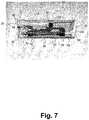
- shows the auto injector of
Fig. 2 with the syringe emptied, - Fig. 8
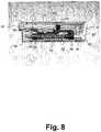
- shows the auto injector of
Fig. 2 with the release member released, - Fig. 9
- shows the auto injector of
Fig. 2 with the retraction lock released, - Fig. 10
- shows the auto injector of
Fig. 2 with the syringe retracted, - Fig. 11
- shows an auto injector according to the invention with a protection cap,
- Fig. 12
- shows the auto injector of
Fig. 11 in a state ready for use and with a part of the housing cut away, - Fig. 13
- shows the auto injector of
Fig. 12 with the protection cap removed, - Fig. 14
- shows the auto injector of
Fig. 12 with the release member activated, - Fig. 15
- shows the auto injector of
Fig. 12 with the injection trigger member activated, - Fig. 16
- shows the auto injector of
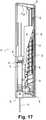
Fig. 12 with the syringe moved to its second position, - Fig. 17
- shows the auto injector of
Fig. 12 with the syringe emptied, - Fig. 18
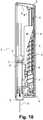
- shows the auto injector of
Fig. 12 with the release member released, - Fig. 19
- shows the auto injector of
Fig. 12 with the retraction lock released, and - Fig. 20
- shows the auto injector of
Fig. 12 with the syringe retracted. - The figures are schematic and simplified for clarity, and they merely show details, which are essential to the understanding of the invention, while other details have been left out. Throughout, the same reference numerals are used for identical or corresponding parts.
- It should be noted that in addition to the exemplary embodiments of the invention shown in the accompanying drawings, the invention may be embodied in different forms and should not be construed as limited to the embodiments set forth herein.
- Rather, these embodiments are provided so that this disclosure will be thorough and complete, and will fully convey the concept of the invention as defined in the appended claims to those skilled in the art.
Fig. 1 shows anauto injector 10 according to the present invention. It has anelongated housing 12 with a substantially rectangular cross-section for an easy grip by hand. The illustrated embodiment may for example have a length of 10 cm, a width of 3 cm, and a thickness of 1.5 cm. Thehousing 12 has an opening at one end thereof closed by aremovable protection cap 14. At the opposite end of the housing is atrigger button 16 that serves as the injection trigger member as further explained below.Fig. 2 shows the auto injector ofFig. 1 with a top part of thehousing 12 removed. Thehousing 12 accommodates asyringe 18 with a needle 20 (not visible). Thesyringe 18 is positioned in a first position with theneedle 20 accommodated within the walls of thehousing 12.- In the illustrated embodiment, a
coil spring 22 serves as the driver for moving thesyringe 18 from the first position, in which position the needle is accommodated inside the housing, to a second position in which position the needle protrudes outside the housing. Thecoil spring 22 is positioned laterally in relation to thesyringe 18 and is compressed so that it applies a force between a first arm, i.e. theplunger arm 24, and a second arm, i.e. theshoulder arm 26. One end of theplunger arm 24 abuts theend 28 of theplunger 30 of thesyringe 18 while the other end is configured with afirst ring 32. A rotatably mountedrelease shaft 34 extends through thefirst ring 32. Protrusions ortongues 36 protruding from therelease shaft 34 and extending in parallel with the longitudinal axis of therelease shaft 34 have end edges abutting thefirst ring 32 and preventing the ring from moving to the left inFig. 2 in response to the force exerted by thecoil spring 22. Likewise, one end of theshoulder arm 26 is configured with asecond ring 38. Therelease shaft 34 also extends through thesecond ring 38. Other protrusions ortongues 40 protruding from therelease shaft 34 and extending in parallel with the longitudinal axis of therelease shaft 34 have end edges abutting thesecond ring 38 and preventing thesecond ring 38 from moving to the right inFig. 2 in response to the force exerted by thecoil spring 22. Thus, the end edges of thetongues 40 abutting thesecond ring 38 form the first anchor location. - In
Fig. 3 , theprotection cap 14 has been removed from theauto injector 10 thereby exposing askin contact button 42 intended to be pressed against the injection site during use and serving as the release member as will be further explained below. - Typically, the
syringe 18 also has a rubber cap (not shown) for protection of theneedle 20 in which case theprotection cap 14 has fingers gripping an edge of the rubber cap so that the rubber cap is removed together with theprotection cap 14. - A
lock arm 44 has an end that abuts thetrigger button 16 so that the user is prevented from depressing the trigger button and thus, from starting automatic injection. Fig. 4 shows theauto injector 10 with theskin contact button 42 depressed whereby thelock arm 44 is released so that it is no longer kept in a fixed position by the pivotally mounted lockingmember 46. Depression of thetrigger button 16 is now possible. Thus, in accordance with the invention, the auto-injector has a second injection lock configured in a locked state for preventing syringe movement from the first position to the second position by user operation of the injection trigger member and a release member configured for releasing the second injection lock to an unlocked state by first user operation of the release member in which unlocked state the second injection lock does not prevent syringe movement from the first position to the second position by user operation of the injection trigger member. In the illustrated example, first user operation of the release member is constituted by the user pressing the release member against the skin surface at the injection site.- In the illustrated embodiment, the second injection lock comprises the
lock arm 44 and the pivotally mounted lockingmember 46. In the locked state shown inFig. 3 , the second injection lock prevents user operation of the injection trigger member, i.e. thetrigger button 16 in the illustrated embodiment, thereby preventing syringe movement from the first position to the second position by user operation of thetrigger button 16. The release member, i.e. theskin contact button 42 in the illustrated embodiment, when pressed against the injection site, releases the second injection lock to an unlocked state allowing depression of thetrigger button 16 by turning the lockingmember 46 so that one end thereof abutting an end of thelock arm 44 moves away from the lock arm so that thelock arm 44 can be displaced together with together with thetrigger button 16, and thus, no longer prevents thetrigger button 16 from being depressed. Fig. 5 shows theauto injector 10 with both theskin contact button 42 and thetrigger button 16 depressed. Thetrigger button 16 has a protrudingflange 48 that abuts atap 50 protruding from therelease shaft 34 perpendicular to its longitudinal axis. When thetrigger button 16 is depressed, the protrudingflange 48 displaces thetap 50 thereby turning therelease shaft 34 an angle of approximately 30° from a first angular position to a second angular position. This turns thetongues 36 of therelease shaft 34 into second angular positions fitting corresponding through-going grooves (not visible) inside thefirst ring 32 of theplunger arm 24. The grooves are sized to accommodate thetongues 36 thereby allowing the ring to slide along therelease shaft 34 with thetongues 36 sliding inside the grooves thereby releasing the plunger arm from its fixed position so that theplunger arm 24 is displaced to the left in the Figures in response to the force of thecoil spring 22. The movedplunger arm 24 pushes theplunger 30 and thereby thesyringe 18 towards its second position.- Thus, in accordance with the invention, the auto injector has a first injection lock configured in a locked state for preventing syringe movement from the first position to the second position and an injection trigger member configured for releasing the first injection lock to an unlocked state by user operation of the injection trigger member in which unlocked state the first injection lock does not prevent the driver from moving the syringe from the first position to the second position.
- In the illustrated embodiment, the first injection lock of the illustrated embodiment comprises the
release shaft 34 withtongues 36 interacting with the corresponding grooves (not visible) in thefirst ring 32 of theplunger arm 24. In the locked state, therelease shaft 34 has a first angular position in which end edges of thetongues 36 abut thefirst ring 32 and prevent movement of theplunger arm 24. Depression of the injection trigger member, i.e. thetrigger button 16 in the illustrated embodiment, releases the first injection lock by the turn of therelease shaft 34 as explained above. Fig. 6 shows thesyringe 18 in its second position wherein theshoulder 52 of thesyringe 18 abuts an end of theshoulder arm 26 and an internal protrusion in thehousing 12. In the second position of thesyringe 18, theneedle 20 is exposed through an aperture in theskin contact button 42.- As shown in
Fig. 7 , theplunger arm 24 continues its movement while thesyringe 18 is kept in its second position whereby thesyringe 18 is emptied and the medication is injected into the user. Theplunger arm 24 is prevented from further movement to the left by abutment with theretraction lock arm 54 which again abuts thepivotable locking member 46 and a guidingprotrusion 56 of theskin contact button 42. - Upon injection, the user removes the
auto injector 10 from the injection site. During removal from the injection site, thesyringe 18 is automatically retracted from its second position so that theneedle 20 is withdrawn into thehousing 12 and kept within the walls of thehousing 12 thereby preventing accidental contact with theneedle 20. - In
Fig. 8 , theauto injector 10 has been removed from the injection site and a resilient member such as a coil spring has forced theskin contact button 42 back to its original position shown inFigs. 1 - 3 . The corresponding displacement of the guidingprotrusion 56 of theskin contact button 42 allows the pivotally mountedretraction lock arm 54 to pivot away from thefirst ring 32 of theplunger arm 24 in response to the force exerted by thecoil spring 22 onfirst ring 32. Since thefirst ring 32 abuts a skew edge of theretraction lock arm 54 further movement of thefirst ring 32 to the left in the Figure is now possible by pivoting theretraction lock arm 54 away from thefirst ring 32. - This is shown in
Fig. 9 . Pivoting theretraction lock arm 54 also disconnects thefirst ring 32 from the remaining part of theplunger arm 24 so that theplunger arm 24 is free to move back to the right together with thesyringe 18. Simultaneous with the pivoting of theplunger arm 24 and further explained below, thefirst ring 32 turns therelease shaft 34 an angle whereby theshoulder arm 26 with thesecond ring 38 is released from its fixed position and since thefirst ring 32 is now kept in a fixed position at the second anchor location, thecoil spring 22 urges the second arm, i.e. theshoulder arm 26 with thesecond ring 38 in the illustrated embodiment, to the right in the Figures and thereby retracts thesyringe 18 by itsshoulder 52 to its original first position constituting the retracted position of thesyringe 18. In the retracted position, theneedle 20 is no longer exposed to the surroundings thereby avoiding health hazards and allowing disposal of the used auto injector. - Further turning of the
release shaft 34 by thefirst ring 32 is possible because the length of thetongues 36 is shorter than the displacement of thefirst ring 32 so that the grooves of thefirst ring 32 do not accommodate thetongues 36 in the position shown inFig. 7 . Then, the turning ofrelease shaft 34 is obtained in a way similar to the turning of therelease shaft 34 by thetrigger button 16 as previously explained. Thus, thefirst ring 32 has an indentation with a skew edge that displaces a second tap (not visible) protruding from therelease shaft 34 perpendicular to its longitudinal axis during its final movement towards the left ofFig. 7 thereby turning therelease shaft 34 another 30°. This causes thetongues 40 at the right end of therelease shaft 34 to be turned and aligned with corresponding through-going grooves in thesecond ring 38 of theshoulder arm 26. The grooves (not visible) are sized to accommodate thetongues 40 so that movement of theshoulder arm 26 to the right of the Figure is made possible and thus, thecoil spring 22 urges theshoulder arm 26 abutting theshoulder 52 of thesyringe 18 to the right thereby retracting thesyringe 18 back into its first position as shown inFig. 10 . - Thus, in accordance with the invention, the auto injector comprises a retraction lock for prevention of retraction of the syringe in a locked state of the retraction lock. In the illustrated embodiment, the retraction lock comprises the locking
member 46, the guidingprotrusion 56, theretraction lock arm 54, and therelease shaft 34 with thetongues 40. The release member, i.e. theskin contact button 42 in the illustrated embodiment, is configured for releasing the retraction lock to an unlocked state by second user operation of the release member, i.e. removal of the auto injector from the injection site thereby releasing theskin contact button 42 from its depressed position to its original position. In its original position, the guidingprotrusion 56 is displaced a distance from theretraction lock arm 54 so that the retraction lock arm can turn away from thefirst ring 32 allowing further movement of thefirst ring 32 to the left releasing the shoulder arm for movement to the right as explained above. - Upon removal of the
auto injector 10 from the injection site, it is not possible to depress theskin contact button 42 again. - It should be noted that the auto injector may be constructed for making injections in more than one step. For example, in a dual chamber syringe, one chamber may contain freeze-dried medicine and a second chamber may contain liquid to be mixed with the freeze-dried medicine. A first actuation of the auto injector may lead to breakage of a seal between the first and second chambers bringing the liquid in contact with the freeze-dried medicine and a second actuation may lead to injection of the mixed medicine. For example, the
release shaft 34 in the illustrated embodiment may contain more than two sets of tongues to be aligned with corresponding grooves in therespective rings release shaft 34 thereby allowing one of therings release shaft 34 has a specific angular position. This makes it possible to use medicine without preservatives which again makes the auto injector more user friendly because most of the pain caused by injections is caused by preservatives in the wound. - It should further be noticed that utilization of a rotatable shaft for controlling displacement of parts in the auto injector by locking the position of specific parts in one angular position of the shaft and unlocking the position in another angular position of the shaft makes the device more resistant to the user dropping the device.
- In prior art devices, locking and unlocking displacement of parts in the auto injector by linear movement of locking parts is inherently sensitive to dropping of the device, since such dropping may induce a linear movement of parts in the device, e.g. causing inadvertent triggering of the device. In the auto injector according to the invention, dropping of the device will not cause rotation of the rotatable shaft, and since the auto injector can not be dropped on the injection trigger member and the release member simultaneously, the device will not inadvertently be triggered by dropping of the device.
Figs. 11 - 20 correspond toFigs. 1 - 10 , respectively, and illustrate the operation of another auto injector according to the invention operating in a way similar to the auto injector illustrated inFigs 1 - 10 and explained above.
Claims (15)
- An auto injector (10) with a housing (12) for accommodation of
a syringe (18) with a needle (20), the syringe (18) being movably positioned in the housing (12) between a first position in which position the needle (20) is accommodated inside the housing (12) and a second position in which position the needle (20) protrudes outside the housing (12),
a mechanical driver (22) anchored to the housing (12) at a first anchor location for applying a force to the syringe (18) thereby moving the syringe (18) from the first position to the second position, the mechanical driver (22) is also configured for applying a force to the syringe (18) by anchoring the mechanical driver (22) to a different second anchor location,
the auto injector (10) further comprising a first arm (24) configured for conveying a force from the mechanical driver (22) to the syringe (18) for moving the syringe (18) from the first position to the second position,
characterized by a second arm (26) configured for conveying a force from the mechanical driver (22) to the syringe shoulder (52) for retracting the syringe (18) from the second position to the retracted position, and wherein the mechanical driver (22) has one end applying a force to the first arm (24) and another end applying a force to the second arm (26), and wherein the second arm (26) is kept in a fixed position during movement of the syringe (18) from the first position to the second position, and wherein the first arm (24) is kept in a fixed position during movement of the syringe (18) from the second position to the retracted position. - An auto injector (10) according to claim 1, wherein the mechanical driver (22) is configured for moving the syringe (18) from the second position to a retracted position in which position the needle (20) is accommodated inside the housing (12), when the mechanical driver (22) is anchored to the second anchor location.
- An auto injector (10) according to claim 1 or 2, wherein the mechanical driver (22) is positioned laterally with relation to the syringe (18).
- An auto injector (10) according to any of the preceding claims, wherein the mechanical driver (22) is a spring.
- An auto injector (10) according to claim 4, wherein the mechanical driver (22) is a coil spring.
- An auto injector (10) according to any of the preceding claims, further comprising a rotatable release shaft (34) configured for rotation between a first angular position in which position the shaft prevents movement of the syringe (18) from the first position to the second position and a second angular position in which position the shaft does not prevent movement of the syringe (18) from the first position to the second position.
- An auto injector (10) according to claim 6, wherein the rotatable release shaft (34) is positioned laterally in relation to the syringe (18).
- An auto injector (10) according to claim 6 or 7 dependent on claim 5, wherein the coil spring is arranged coaxially with the rotatable release shaft (34).
- An auto injector (10) according to any of claims 6 - 8, wherein an injection trigger member (16) is coupled to the rotatable release shaft (34) and configured to turn the release shaft (34) from the first angular position to the second angular position by user operation.
- An auto injector (10) according to claim 9, wherein the injection trigger member (16) has a flange (48) that abuts a tap (50) protruding from the release shaft (34) perpendicular to the longitudinal axis of the release shaft (34) in such a way that movement of the injection trigger member (16) with the flange (48) displaces the tap (50) thereby turning the release shaft (34) an angle from the first angular position to the second angular position.
- An auto injector (10) according to any of claims 6 - 10, wherein the release shaft (34) is further configured for rotation between a third angular position in which position movement of the syringe (18) from the second position to the retracted position is prevented and a fourth angular position in which position movement of the syringe (18) from the second position to the retracted position is not prevented.
- An auto injector (10) according to any of the preceding claims, wherein the first arm (24) has a first ring (32) positioned in such a way that a release shaft (34) extends through the first ring (32), and wherein the release shaft (34) has first tongues (36) protruding from the release shaft (34) and extending in parallel with the longitudinal axis of the release shaft (34) with end edges abutting the first ring (32) in one angular position of the release shaft (34) thereby preventing the first ring (32) from moving in the direction of the first tongues (36) in response to the force applied to the first arm (24) by the mechanical driver (22).
- An auto injector (10) according to claim 12, wherein the first ring (32) has through-going grooves in its inner circular circumferential surface abutting the release shaft (34) positioned in such a way that the first tongues (36) of the release shaft (34) in another angular position of the release shaft (34) fit respective through-going grooves in the inner circular circumferential surface of the first ring (32), the grooves being sized to accommodate the tongues (36) thereby allowing the first ring (32) to slide along the release shaft (34) with the tongues (36) sliding in the grooves so that the first ring (32) can be displaced in the direction of the first tongues (36) in response to the force applied to the first arm (24) by the mechanical driver (22).
- An auto injector (10) according to any of claims 1-13, wherein the second arm (26) has a second ring (38) positioned in such a way that a release shaft (34) extends through the second ring (38), and wherein the release shaft (34) has second tongues (40) protruding from the release shaft (34) and extending in parallel with the longitudinal axis of the release shaft (34) and displaced along the longitudinal axis of the release shaft (34) in relation to the first tongues (36) and having end edges abutting the second ring (38) in the other angular position of the release shaft (34) thereby preventing the second ring (38) from moving in the direction of the second tongues (40) in response to the force applied to the second arm (26) by the mechanical driver (22).
- An auto injector (10) according to claim 14, wherein the second ring (38) has through-going grooves in its inner circular circumferential surface abutting the release shaft (34) positioned in such a way that the second tongues (40) of the release shaft (34) in a third angular position of the release shaft (34) fit respective through-going grooves in the inner circular circumferential surface of the second ring (38), the grooves being sized to accommodate the second tongues (40) thereby allowing the second ring (38) to slide along the release shaft (34) with the second tongues (40) sliding in the grooves so that the second ring (38) can be displaced in the direction of the second tongues (40) in response to the force applied to the second arm (26) by the mechanical driver (22).
Applications Claiming Priority (6)
| Application Number | Priority Date | Filing Date | Title |
|---|---|---|---|
| DKPA200701596 | 2007-11-12 | ||
| US99634407P | 2007-11-13 | 2007-11-13 | |
| DKPA200701867 | 2007-12-21 | ||
| DKPA200701870 | 2007-12-21 | ||
| DKPA200701869 | 2007-12-21 | ||
| PCT/DK2008/000400WO2009062509A1 (en) | 2007-11-12 | 2008-11-12 | Auto injector with changing anchor locations for a mechanical driver |
Publications (2)
| Publication Number | Publication Date |
|---|---|
| EP2224980A1 EP2224980A1 (en) | 2010-09-08 |
| EP2224980B1true EP2224980B1 (en) | 2018-07-25 |
Family
ID=40638350
Family Applications (3)
| Application Number | Title | Priority Date | Filing Date |
|---|---|---|---|
| EP08850160.6ANot-in-forceEP2224979B1 (en) | 2007-11-12 | 2008-11-12 | Auto injector with a rotatable release shaft |
| EP08850508.6ANot-in-forceEP2224980B1 (en) | 2007-11-12 | 2008-11-12 | Auto injector with changing anchor locations for a mechanical driver |
| EP08848709.5AActiveEP2219710B2 (en) | 2007-11-12 | 2008-11-12 | Auto injector with automatic needle retraction |
Family Applications Before (1)
| Application Number | Title | Priority Date | Filing Date |
|---|---|---|---|
| EP08850160.6ANot-in-forceEP2224979B1 (en) | 2007-11-12 | 2008-11-12 | Auto injector with a rotatable release shaft |
Family Applications After (1)
| Application Number | Title | Priority Date | Filing Date |
|---|---|---|---|
| EP08848709.5AActiveEP2219710B2 (en) | 2007-11-12 | 2008-11-12 | Auto injector with automatic needle retraction |
Country Status (7)
| Country | Link |
|---|---|
| US (3) | US8956331B2 (en) |
| EP (3) | EP2224979B1 (en) |
| CN (2) | CN101909674B (en) |
| AT (1) | ATE506091T1 (en) |
| DE (1) | DE602008006458D1 (en) |
| ES (2) | ES2688900T3 (en) |
| WO (3) | WO2009062509A1 (en) |
Families Citing this family (121)
| Publication number | Priority date | Publication date | Assignee | Title |
|---|---|---|---|---|
| WO2003068290A2 (en) | 2002-02-11 | 2003-08-21 | Antares Pharma, Inc. | Intradermal injector |
| GB2414400B (en) | 2004-05-28 | 2009-01-14 | Cilag Ag Int | Injection device |
| GB2414402B (en) | 2004-05-28 | 2009-04-22 | Cilag Ag Int | Injection device |
| GB2414775B (en) | 2004-05-28 | 2008-05-21 | Cilag Ag Int | Releasable coupling and injection device |
| HUE042286T2 (en) | 2005-01-24 | 2019-06-28 | Antares Pharma Inc | Needle-filled pre-filled syringe |
| GB2424836B (en) | 2005-04-06 | 2010-09-22 | Cilag Ag Int | Injection device (bayonet cap removal) |
| GB2425062B (en) | 2005-04-06 | 2010-07-21 | Cilag Ag Int | Injection device |
| PL1759729T3 (en) | 2005-08-30 | 2010-09-30 | Cilag Gmbh Int | Needle assembly for a prefilled syringe system |
| US20110098656A1 (en) | 2005-09-27 | 2011-04-28 | Burnell Rosie L | Auto-injection device with needle protecting cap having outer and inner sleeves |
| WO2007131025A1 (en) | 2006-05-03 | 2007-11-15 | Antares Pharma, Inc. | Injector with adjustable dosing |
| WO2007131013A1 (en) | 2006-05-03 | 2007-11-15 | Antares Pharma, Inc. | Two-stage reconstituting injector |
| GB2438591B (en) | 2006-06-01 | 2011-07-13 | Cilag Gmbh Int | Injection device |
| BRPI0817907B8 (en) | 2007-10-02 | 2021-06-22 | Lamodel Ltd | apparatus for administering a substance to an individual |
| EP3636301A1 (en) | 2008-03-10 | 2020-04-15 | Antares Pharma, Inc. | Injector safety device |
| US8052645B2 (en) | 2008-07-23 | 2011-11-08 | Avant Medical Corp. | System and method for an injection using a syringe needle |
| US8177749B2 (en)* | 2008-05-20 | 2012-05-15 | Avant Medical Corp. | Cassette for a hidden injection needle |
| CA3070618C (en) | 2008-05-20 | 2021-07-20 | Avant Medical Corp. | Autoinjector system |
| GB2461085B (en) | 2008-06-19 | 2012-08-29 | Cilag Gmbh Int | Injection device |
| GB2461088B (en)* | 2008-06-19 | 2012-09-26 | Cilag Gmbh Int | Injection device |
| US8376993B2 (en) | 2008-08-05 | 2013-02-19 | Antares Pharma, Inc. | Multiple dosage injector |
| GB0900930D0 (en) | 2009-01-20 | 2009-03-04 | Future Injection Technologies Ltd | Injection device |
| JP5732039B2 (en) | 2009-03-20 | 2015-06-10 | アンタレス・ファーマ・インコーポレーテッド | Hazardous drug injection system |
| DK2536452T3 (en) | 2010-02-18 | 2019-01-02 | Sanofi Aventis Deutschland | autoinjector |
| AU2015203703B2 (en)* | 2010-05-20 | 2018-01-18 | Becton, Dickinson And Company | Drug delivery device |
| BR112012029642B1 (en) | 2010-05-20 | 2020-05-26 | Becton, Dickinson And Company | DRUG ADMINISTRATION DEVICE |
| EP2399632A1 (en)* | 2010-06-28 | 2011-12-28 | Sanofi-Aventis Deutschland GmbH | Auto injector with a single compression spring and a laterraly trigger button |
| EP2399628A1 (en)* | 2010-06-28 | 2011-12-28 | Sanofi-Aventis Deutschland GmbH | Auto-injector |
| EP2399629A1 (en)* | 2010-06-28 | 2011-12-28 | Sanofi-Aventis Deutschland GmbH | Auto-injector |
| EP2399635A1 (en) | 2010-06-28 | 2011-12-28 | Sanofi-Aventis Deutschland GmbH | Auto-injector |
| EP2399630A1 (en)* | 2010-06-28 | 2011-12-28 | Sanofi-Aventis Deutschland GmbH | Auto-injector |
| US9427531B2 (en) | 2010-06-28 | 2016-08-30 | Sanofi-Aventis Deutschland Gmbh | Auto-injector |
| CN103167887B (en) | 2010-08-27 | 2015-07-15 | 诺沃—诺迪斯克有限公司 | Medical injection device |
| EP2438943A1 (en)* | 2010-10-08 | 2012-04-11 | Sanofi-Aventis Deutschland GmbH | Auto-injector |
| EP2438947A1 (en)* | 2010-10-08 | 2012-04-11 | Sanofi-Aventis Deutschland GmbH | Auto-injector |
| EP2438942A1 (en)* | 2010-10-08 | 2012-04-11 | Sanofi-Aventis Deutschland GmbH | Auto-injector |
| JP5940545B2 (en)* | 2010-10-08 | 2016-06-29 | サノフィ−アベンティス・ドイチュラント・ゲゼルシャフト・ミット・ベシュレンクテル・ハフツング | Automatic syringe |
| USRE48593E1 (en) | 2010-12-21 | 2021-06-15 | Sanofi-Aventis Deutschland Gmbh | Auto-injector |
| EP2468334A1 (en) | 2010-12-21 | 2012-06-27 | Sanofi-Aventis Deutschland GmbH | Auto-injector |
| EP2468331A1 (en) | 2010-12-21 | 2012-06-27 | Sanofi-Aventis Deutschland GmbH | Auto-injector |
| EP2468330A1 (en) | 2010-12-21 | 2012-06-27 | Sanofi-Aventis Deutschland GmbH | Auto-injector |
| EP2468328A1 (en) | 2010-12-21 | 2012-06-27 | Sanofi-Aventis Deutschland GmbH | Auto-injector |
| EP2468336A1 (en) | 2010-12-21 | 2012-06-27 | Sanofi-Aventis Deutschland GmbH | Auto-injector |
| EP2468333A1 (en) | 2010-12-21 | 2012-06-27 | Sanofi-Aventis Deutschland GmbH | Auto-injector |
| US9173999B2 (en) | 2011-01-26 | 2015-11-03 | Kaleo, Inc. | Devices and methods for delivering medicaments from a multi-chamber container |
| EP2489382A1 (en) | 2011-02-18 | 2012-08-22 | Sanofi-Aventis Deutschland GmbH | Auto-injector |
| EP2489380A1 (en) | 2011-02-18 | 2012-08-22 | Sanofi-Aventis Deutschland GmbH | Injection device |
| EP2489381A1 (en) | 2011-02-18 | 2012-08-22 | Sanofi-Aventis Deutschland GmbH | Auto-injector |
| EP2489389A1 (en) | 2011-02-18 | 2012-08-22 | Sanofi-Aventis Deutschland GmbH | Detent mechanism |
| EP2489385A1 (en) | 2011-02-18 | 2012-08-22 | Sanofi-Aventis Deutschland GmbH | Auto-injector |
| EP2489384A1 (en) | 2011-02-18 | 2012-08-22 | Sanofi-Aventis Deutschland GmbH | Auto-injector |
| EP2489386A1 (en) | 2011-02-18 | 2012-08-22 | Sanofi-Aventis Deutschland GmbH | Auto-injector |
| EP2489387A1 (en) | 2011-02-18 | 2012-08-22 | Sanofi-Aventis Deutschland GmbH | Auto-injector |
| EP2489388A1 (en) | 2011-02-18 | 2012-08-22 | Sanofi-Aventis Deutschland GmbH | Auto-injector |
| PL2699293T3 (en) | 2011-04-20 | 2019-08-30 | Amgen Inc. | Autoinjector apparatus |
| US9220660B2 (en) | 2011-07-15 | 2015-12-29 | Antares Pharma, Inc. | Liquid-transfer adapter beveled spike |
| US8496619B2 (en) | 2011-07-15 | 2013-07-30 | Antares Pharma, Inc. | Injection device with cammed ram assembly |
| EP2606924A1 (en) | 2011-12-21 | 2013-06-26 | Sanofi-Aventis Deutschland GmbH | Autoinjector having a retracting syringe carrier |
| US9486583B2 (en) | 2012-03-06 | 2016-11-08 | Antares Pharma, Inc. | Prefilled syringe with breakaway force feature |
| EP4186545A1 (en) | 2012-04-06 | 2023-05-31 | Antares Pharma, Inc. | Needle assisted jet injection administration of testosterone compositions |
| KR101666290B1 (en)* | 2012-04-10 | 2016-10-24 | 케어베이 유럽 리미티드 | Infusion device |
| USD808010S1 (en) | 2012-04-20 | 2018-01-16 | Amgen Inc. | Injection device |
| USD898908S1 (en) | 2012-04-20 | 2020-10-13 | Amgen Inc. | Pharmaceutical product cassette for an injection device |
| US9364610B2 (en) | 2012-05-07 | 2016-06-14 | Antares Pharma, Inc. | Injection device with cammed ram assembly |
| WO2013175144A1 (en)* | 2012-05-25 | 2013-11-28 | Aptar France Sas | Autoinjector |
| WO2013175136A1 (en) | 2012-05-25 | 2013-11-28 | Aptar France Sas | Autoinjector |
| CN104394909B (en) | 2012-05-25 | 2017-03-29 | 阿普塔尔法国简易股份公司 | Automatic injector |
| EP2854901B1 (en) | 2012-05-25 | 2019-10-02 | Aptar France SAS | Autoinjector comprising a time delay device having a planetary gear set for delaying the retraction of the needle |
| FR2990865B1 (en)* | 2012-05-25 | 2015-04-24 | Valois Sas | autoinjector |
| HUE026766T2 (en)* | 2012-09-05 | 2016-07-28 | Becton Dickinson France | Automatic injection device |
| EP2705862B1 (en)* | 2012-09-05 | 2015-07-08 | Becton Dickinson France | Automatic injection device |
| EP3308814B1 (en) | 2012-09-27 | 2020-11-18 | APTAR France SAS | Autoinjector |
| JP6140829B2 (en)* | 2012-10-05 | 2017-05-31 | ケアベイ・ヨーロッパ・リミテッドCarebay Europe Limited | Drug delivery device |
| EP2727617A1 (en)* | 2012-11-06 | 2014-05-07 | Sanofi-Aventis Deutschland GmbH | Autoinjector |
| FI3659647T3 (en) | 2013-02-11 | 2024-03-28 | Antares Pharma Inc | NEEDLE-ASSISTED SPRAY INJECTOR WITH REDUCED TRIGGER FORCE |
| CA2905031C (en) | 2013-03-11 | 2018-01-23 | Hans PFLAUMER | Dosage injector with pinion system |
| WO2014165136A1 (en) | 2013-03-12 | 2014-10-09 | Antares Pharma, Inc. | Constant volume prefilled syringes and kits thereof |
| ES2973257T3 (en) | 2013-03-15 | 2024-06-19 | Amgen Inc | Drug cassette, autoinjector and autoinjector system |
| CA2904661C (en) | 2013-03-15 | 2022-03-15 | Amgen Inc. | Drug cassette, autoinjector, and autoinjector system |
| ES2688320T3 (en)* | 2013-05-24 | 2018-10-31 | Becton Dickinson France | Automatic injection device |
| GB2515038A (en) | 2013-06-11 | 2014-12-17 | Cilag Gmbh Int | Injection device |
| GB2515039B (en) | 2013-06-11 | 2015-05-27 | Cilag Gmbh Int | Injection Device |
| GB2515032A (en) | 2013-06-11 | 2014-12-17 | Cilag Gmbh Int | Guide for an injection device |
| GB2517896B (en) | 2013-06-11 | 2015-07-08 | Cilag Gmbh Int | Injection device |
| ES2728054T3 (en) | 2013-06-18 | 2019-10-22 | Enable Injections Inc | Vial transfer and injection device |
| EP2823841A1 (en) | 2013-07-09 | 2015-01-14 | Sanofi-Aventis Deutschland GmbH | Autoinjector |
| US9474862B2 (en) | 2013-12-16 | 2016-10-25 | Jessica Walsh | Wearable medication administration device |
| EP2923714A1 (en) | 2014-03-28 | 2015-09-30 | Sanofi-Aventis Deutschland GmbH | Autoinjector triggered by skin contact |
| JP6629231B2 (en) | 2014-04-04 | 2020-01-15 | ノボ・ノルデイスク・エー/エス | Automatic injection device with needle shield trigger |
| WO2015164648A1 (en) | 2014-04-24 | 2015-10-29 | Becton, Dickinson And Company | Catheter insertion mechanism for a patch pump |
| CA3009221A1 (en) | 2014-12-23 | 2016-06-30 | Automed Pty Ltd | Delivery apparatus, system and associated methods |
| IL295010B1 (en) | 2015-03-10 | 2025-06-01 | Regeneron Pharma | Pollution-free piercing system and method |
| TW201707738A (en) | 2015-06-03 | 2017-03-01 | 賽諾菲阿凡提斯德意志有限公司 | Syringe holder and autoinjector (2) |
| CA2990950A1 (en) | 2015-06-30 | 2017-01-05 | Kaleo, Inc. | Auto-injectors for administration of a medicament within a prefilled syringe |
| US10576207B2 (en) | 2015-10-09 | 2020-03-03 | West Pharma. Services IL, Ltd. | Angled syringe patch injector |
| US11318254B2 (en) | 2015-10-09 | 2022-05-03 | West Pharma. Services IL, Ltd. | Injector needle cap remover |
| GB2545266B (en)* | 2015-12-11 | 2018-08-08 | Oval Medical Tech Limited | Autoinjector with retracting needle |
| EP3711793B1 (en) | 2016-01-21 | 2021-12-01 | West Pharma Services IL, Ltd. | A method of connecting a cartridge to an automatic injector |
| JP6885960B2 (en) | 2016-01-21 | 2021-06-16 | ウェスト ファーマ サービシーズ イスラエル リミテッド | Drug delivery device with visual indicators |
| US10646643B2 (en) | 2016-01-21 | 2020-05-12 | West Pharma. Services IL, Ltd. | Needle insertion and retraction mechanism |
| US11389597B2 (en) | 2016-03-16 | 2022-07-19 | West Pharma. Services IL, Ltd. | Staged telescopic screw assembly having different visual indicators |
| ES2944914T3 (en)* | 2016-03-16 | 2023-06-27 | Lilly Co Eli | Medication injection device with automatic needle retraction after injection |
| JP6617203B2 (en) | 2016-03-16 | 2019-12-11 | イーライ リリー アンド カンパニー | Trigger assembly for automatic drug injection device |
| US10376656B2 (en)* | 2016-05-18 | 2019-08-13 | Portal Instruments, Inc. | Side-angle decapping of pre-filled syringe |
| JP7059251B2 (en) | 2016-08-01 | 2022-04-25 | ウェスト ファーマ サービシーズ イスラエル リミテッド | A spring that prevents the door from closing halfway |
| US11338090B2 (en) | 2016-08-01 | 2022-05-24 | West Pharma. Services IL, Ltd. | Anti-rotation cartridge pin |
| JP6970733B2 (en)* | 2016-08-02 | 2021-11-24 | サノフィ−アベンティス・ドイチュラント・ゲゼルシャフト・ミット・ベシュレンクテル・ハフツング | Drug delivery device |
| US10702652B2 (en)* | 2016-11-15 | 2020-07-07 | Adam Teach | Injection device |
| WO2018119218A1 (en) | 2016-12-23 | 2018-06-28 | Kaleo, Inc. | Medicament delivery device and methods for delivering drugs to infants and children |
| CN119950880A (en) | 2017-05-05 | 2025-05-09 | 里珍纳龙药品有限公司 | Auto-injectors and related methods of use |
| EP3630226A1 (en) | 2017-05-30 | 2020-04-08 | West Pharma. Services Il, Ltd. | Modular drive train for wearable injector |
| JP7324191B2 (en) | 2017-08-30 | 2023-08-09 | ピルエット メディカル エルエルシー | compact auto-injector |
| US10441714B2 (en) | 2017-10-05 | 2019-10-15 | Pirouette Medical LLC | Protective case for an auto-injector |
| GB2567819A (en)* | 2017-10-24 | 2019-05-01 | Ndm Technologies Ltd | Improvements in or relating to injector devices |
| WO2019116229A1 (en) | 2017-12-11 | 2019-06-20 | Target Point Technologies Ltd. | Intranasal administration device |
| US12364819B2 (en)* | 2019-02-12 | 2025-07-22 | Eli Lilly And Company | Fluidic subsystem for multi-use drug-delivery device |
| CA3145580A1 (en) | 2019-08-09 | 2021-02-18 | Kaleo, Inc. | Devices and methods for delivery of substances within a prefilled syringe |
| US11957542B2 (en) | 2020-04-30 | 2024-04-16 | Automed Patent Holdco, Llc | Sensing complete injection for animal injection device |
| EP4196193A1 (en)* | 2020-08-14 | 2023-06-21 | Phi-Tech Animal Health Technologies Ltd. | Injection apparatus and method for aquatic species |
| US12268847B1 (en) | 2021-02-10 | 2025-04-08 | Kaleo, Inc. | Devices and methods for delivery of substances within a medicament container |
| USD1007676S1 (en) | 2021-11-16 | 2023-12-12 | Regeneron Pharmaceuticals, Inc. | Wearable autoinjector |
| US11717612B1 (en)* | 2022-09-14 | 2023-08-08 | Robert Backstein | Multi-purpose automatic injector |
Family Cites Families (28)
| Publication number | Priority date | Publication date | Assignee | Title |
|---|---|---|---|---|
| US2605766A (en) | 1943-08-10 | 1952-08-05 | Auguste Rooseboom | Automatic hypodermic needle |
| CH323176A (en) | 1954-06-28 | 1957-07-15 | Deare Soc | Actuator on a medical syringe |
| US4227528A (en)* | 1978-12-26 | 1980-10-14 | Wardlaw Stephen C | Automatic disposable hypodermic syringe |
| US4832682A (en)† | 1984-08-08 | 1989-05-23 | Survival Technology, Inc. | Injection method and apparatus with electrical blood absorbing stimulation |
| US4681566A (en)* | 1984-11-30 | 1987-07-21 | Strato Medical Corporation | Infusion device |
| FR2616221A1 (en)* | 1987-06-02 | 1988-12-09 | Archambeaud Philippe | Device for automatic injection of products and in particular medicinal products contained in a syringe or other injection system |
| US5267963A (en)* | 1992-08-21 | 1993-12-07 | Nicholas Bachynsky | Medication injection device |
| US5478316A (en) | 1994-02-02 | 1995-12-26 | Becton, Dickinson And Company | Automatic self-injection device |
| FR2774294B1 (en)* | 1998-02-04 | 2000-04-14 | Marc Brunel | DEVICE FOR AUTOMATICALLY INJECTING A DOSE OF MEDICINAL PRODUCT |
| SE9803662D0 (en)* | 1998-10-26 | 1998-10-26 | Pharmacia & Upjohn Ab | autoinjector |
| JP4236842B2 (en) | 1999-10-22 | 2009-03-11 | アンタレス・ファーマ・インコーポレーテッド | Medical syringe and drug loading system used therewith |
| AU2001281753A1 (en)* | 2000-08-29 | 2002-03-13 | Novo-Nordisk A/S | Automatic injection device with torsion function for retraction of needle |
| SE518981C2 (en)* | 2000-12-14 | 2002-12-17 | Shl Medical Ab | autoinjector |
| IL156245A0 (en) | 2000-12-22 | 2004-01-04 | Dca Design Int Ltd | Drive mechanism for an injection device |
| US20030105430A1 (en) | 2001-11-30 | 2003-06-05 | Elan Pharma International Limited Wil House | Automatic injector |
| US6979316B1 (en) | 2002-05-23 | 2005-12-27 | Seedlings Life Science Ventures Llc | Apparatus and method for rapid auto-injection of medication |
| US7128727B2 (en)* | 2002-09-30 | 2006-10-31 | Flaherty J Christopher | Components and methods for patient infusion device |
| GB0229345D0 (en)* | 2002-12-17 | 2003-01-22 | Safe T Ltd | Hollow needle applicators |
| US20050027255A1 (en) | 2003-07-31 | 2005-02-03 | Sid Technologies, Llc | Automatic injector |
| EP1703929B1 (en)* | 2003-12-18 | 2009-10-21 | Tecpharma Licensing AG | Releasable injection device |
| CN100574821C (en) | 2003-12-18 | 2009-12-30 | 特克法马许可公司 | releasable injection device |
| US20050222539A1 (en) | 2004-03-30 | 2005-10-06 | Pediamed Pharmaceuticals, Inc. | Automatic injection device |
| EP1814616A1 (en) | 2004-11-04 | 2007-08-08 | Sid Technologies Llc | Automatic injector |
| CN101282756A (en)* | 2005-06-21 | 2008-10-08 | 伊莱利利公司 | Apparatus and method for injecting a pharmaceutical |
| DE102005038933A1 (en)* | 2005-08-17 | 2007-02-22 | L + N Plast Vertriebs Gmbh | Autoinjector |
| DE202005014958U1 (en) | 2005-09-22 | 2005-12-08 | Dieter Hölzle Technik-Projekte GmbH | Injection unit comprising a seat for a syringe body with two pistons and two chambers and a means for driving the plunger to produce a mixing stroke before an injection stroke |
| WO2007099044A1 (en) | 2006-03-03 | 2007-09-07 | Shl Medical Ab | Medical device with orientation sensitive priming mechanism |
| WO2007129324A2 (en) | 2006-05-09 | 2007-11-15 | Gil Yigal | A disposable injecting device with auto-retraction mechanism |
- 2008
- 2008-11-12DEDE602008006458Tpatent/DE602008006458D1/enactiveActive
- 2008-11-12WOPCT/DK2008/000400patent/WO2009062509A1/enactiveApplication Filing
- 2008-11-12USUS12/742,297patent/US8956331B2/enactiveActive
- 2008-11-12USUS12/742,295patent/US8876779B2/enactiveActive
- 2008-11-12EPEP08850160.6Apatent/EP2224979B1/ennot_activeNot-in-force
- 2008-11-12WOPCT/DK2008/000401patent/WO2009062510A1/enactiveApplication Filing
- 2008-11-12USUS12/742,288patent/US8409141B2/ennot_activeExpired - Fee Related
- 2008-11-12WOPCT/DK2008/000399patent/WO2009062508A1/enactiveApplication Filing
- 2008-11-12ESES08850508.6Tpatent/ES2688900T3/enactiveActive
- 2008-11-12CNCN2008801239099Apatent/CN101909674B/ennot_activeExpired - Fee Related
- 2008-11-12ATAT08848709Tpatent/ATE506091T1/ennot_activeIP Right Cessation
- 2008-11-12ESES08850160.6Tpatent/ES2668367T3/enactiveActive
- 2008-11-12EPEP08850508.6Apatent/EP2224980B1/ennot_activeNot-in-force
- 2008-11-12CNCN200880123908.4Apatent/CN102083486B/ennot_activeExpired - Fee Related
- 2008-11-12EPEP08848709.5Apatent/EP2219710B2/enactiveActive
Non-Patent Citations (1)
| Title |
|---|
| None* |
Also Published As
| Publication number | Publication date |
|---|---|
| US8409141B2 (en) | 2013-04-02 |
| CN101909674B (en) | 2013-04-10 |
| US8876779B2 (en) | 2014-11-04 |
| EP2224980A1 (en) | 2010-09-08 |
| DE602008006458D1 (en) | 2011-06-01 |
| US20110224621A1 (en) | 2011-09-15 |
| WO2009062510A1 (en) | 2009-05-22 |
| WO2009062508A1 (en) | 2009-05-22 |
| EP2219710B1 (en) | 2011-04-20 |
| CN102083486B (en) | 2015-01-28 |
| US8956331B2 (en) | 2015-02-17 |
| EP2224979A1 (en) | 2010-09-08 |
| CN102083486A (en) | 2011-06-01 |
| EP2219710B2 (en) | 2020-08-05 |
| ATE506091T1 (en) | 2011-05-15 |
| EP2219710A1 (en) | 2010-08-25 |
| US20100312195A1 (en) | 2010-12-09 |
| EP2224979B1 (en) | 2018-01-17 |
| WO2009062509A1 (en) | 2009-05-22 |
| ES2668367T3 (en) | 2018-05-17 |
| CN101909674A (en) | 2010-12-08 |
| US20110224620A1 (en) | 2011-09-15 |
| ES2688900T3 (en) | 2018-11-07 |
Similar Documents
| Publication | Publication Date | Title |
|---|---|---|
| EP2224980B1 (en) | Auto injector with changing anchor locations for a mechanical driver | |
| US8911412B2 (en) | Interlock mechanism for a drug delivery device and drug delivery device | |
| AU2011329574B2 (en) | Medicament delivery device | |
| US8517988B2 (en) | Motor mechanism for a drug delivery device and drug delivery device | |
| EP3055005B1 (en) | Medicament delivery device | |
| JP2009514572A (en) | Trigger element to activate automatic syringe | |
| JP7143323B2 (en) | Automatic fluid injector | |
| EP4065195A1 (en) | Drive assembly for a medicament delivery device |
Legal Events
| Date | Code | Title | Description |
|---|---|---|---|
| PUAI | Public reference made under article 153(3) epc to a published international application that has entered the european phase | Free format text:ORIGINAL CODE: 0009012 | |
| 17P | Request for examination filed | Effective date:20100614 | |
| AK | Designated contracting states | Kind code of ref document:A1 Designated state(s):AT BE BG CH CY CZ DE DK EE ES FI FR GB GR HR HU IE IS IT LI LT LU LV MC MT NL NO PL PT RO SE SI SK TR | |
| AX | Request for extension of the european patent | Extension state:AL BA MK RS | |
| DAX | Request for extension of the european patent (deleted) | ||
| 17Q | First examination report despatched | Effective date:20160810 | |
| RAP1 | Party data changed (applicant data changed or rights of an application transferred) | Owner name:MEDICOM INNOVATION PARTNER A/S | |
| GRAP | Despatch of communication of intention to grant a patent | Free format text:ORIGINAL CODE: EPIDOSNIGR1 | |
| INTG | Intention to grant announced | Effective date:20180412 | |
| GRAS | Grant fee paid | Free format text:ORIGINAL CODE: EPIDOSNIGR3 | |
| GRAA | (expected) grant | Free format text:ORIGINAL CODE: 0009210 | |
| AK | Designated contracting states | Kind code of ref document:B1 Designated state(s):AT BE BG CH CY CZ DE DK EE ES FI FR GB GR HR HU IE IS IT LI LT LU LV MC MT NL NO PL PT RO SE SI SK TR | |
| REG | Reference to a national code | Ref country code:GB Ref legal event code:FG4D | |
| REG | Reference to a national code | Ref country code:CH Ref legal event code:EP | |
| REG | Reference to a national code | Ref country code:AT Ref legal event code:REF Ref document number:1021082 Country of ref document:AT Kind code of ref document:T Effective date:20180815 | |
| REG | Reference to a national code | Ref country code:DE Ref legal event code:R096 Ref document number:602008056170 Country of ref document:DE | |
| REG | Reference to a national code | Ref country code:IE Ref legal event code:FG4D | |
| REG | Reference to a national code | Ref country code:ES Ref legal event code:FG2A Ref document number:2688900 Country of ref document:ES Kind code of ref document:T3 Effective date:20181107 | |
| REG | Reference to a national code | Ref country code:NL Ref legal event code:MP Effective date:20180725 | |
| REG | Reference to a national code | Ref country code:LT Ref legal event code:MG4D | |
| PG25 | Lapsed in a contracting state [announced via postgrant information from national office to epo] | Ref country code:NL Free format text:LAPSE BECAUSE OF FAILURE TO SUBMIT A TRANSLATION OF THE DESCRIPTION OR TO PAY THE FEE WITHIN THE PRESCRIBED TIME-LIMIT Effective date:20180725 | |
| REG | Reference to a national code | Ref country code:AT Ref legal event code:MK05 Ref document number:1021082 Country of ref document:AT Kind code of ref document:T Effective date:20180725 | |
| PG25 | Lapsed in a contracting state [announced via postgrant information from national office to epo] | Ref country code:NO Free format text:LAPSE BECAUSE OF FAILURE TO SUBMIT A TRANSLATION OF THE DESCRIPTION OR TO PAY THE FEE WITHIN THE PRESCRIBED TIME-LIMIT Effective date:20181025 Ref country code:FI Free format text:LAPSE BECAUSE OF FAILURE TO SUBMIT A TRANSLATION OF THE DESCRIPTION OR TO PAY THE FEE WITHIN THE PRESCRIBED TIME-LIMIT Effective date:20180725 Ref country code:GR Free format text:LAPSE BECAUSE OF FAILURE TO SUBMIT A TRANSLATION OF THE DESCRIPTION OR TO PAY THE FEE WITHIN THE PRESCRIBED TIME-LIMIT Effective date:20181026 Ref country code:SE Free format text:LAPSE BECAUSE OF FAILURE TO SUBMIT A TRANSLATION OF THE DESCRIPTION OR TO PAY THE FEE WITHIN THE PRESCRIBED TIME-LIMIT Effective date:20180725 Ref country code:LT Free format text:LAPSE BECAUSE OF FAILURE TO SUBMIT A TRANSLATION OF THE DESCRIPTION OR TO PAY THE FEE WITHIN THE PRESCRIBED TIME-LIMIT Effective date:20180725 Ref country code:AT Free format text:LAPSE BECAUSE OF FAILURE TO SUBMIT A TRANSLATION OF THE DESCRIPTION OR TO PAY THE FEE WITHIN THE PRESCRIBED TIME-LIMIT Effective date:20180725 Ref country code:PL Free format text:LAPSE BECAUSE OF FAILURE TO SUBMIT A TRANSLATION OF THE DESCRIPTION OR TO PAY THE FEE WITHIN THE PRESCRIBED TIME-LIMIT Effective date:20180725 Ref country code:IS Free format text:LAPSE BECAUSE OF FAILURE TO SUBMIT A TRANSLATION OF THE DESCRIPTION OR TO PAY THE FEE WITHIN THE PRESCRIBED TIME-LIMIT Effective date:20181125 Ref country code:BG Free format text:LAPSE BECAUSE OF FAILURE TO SUBMIT A TRANSLATION OF THE DESCRIPTION OR TO PAY THE FEE WITHIN THE PRESCRIBED TIME-LIMIT Effective date:20181025 | |
| PG25 | Lapsed in a contracting state [announced via postgrant information from national office to epo] | Ref country code:LV Free format text:LAPSE BECAUSE OF FAILURE TO SUBMIT A TRANSLATION OF THE DESCRIPTION OR TO PAY THE FEE WITHIN THE PRESCRIBED TIME-LIMIT Effective date:20180725 Ref country code:HR Free format text:LAPSE BECAUSE OF FAILURE TO SUBMIT A TRANSLATION OF THE DESCRIPTION OR TO PAY THE FEE WITHIN THE PRESCRIBED TIME-LIMIT Effective date:20180725 | |
| REG | Reference to a national code | Ref country code:DE Ref legal event code:R097 Ref document number:602008056170 Country of ref document:DE | |
| PG25 | Lapsed in a contracting state [announced via postgrant information from national office to epo] | Ref country code:EE Free format text:LAPSE BECAUSE OF FAILURE TO SUBMIT A TRANSLATION OF THE DESCRIPTION OR TO PAY THE FEE WITHIN THE PRESCRIBED TIME-LIMIT Effective date:20180725 Ref country code:CZ Free format text:LAPSE BECAUSE OF FAILURE TO SUBMIT A TRANSLATION OF THE DESCRIPTION OR TO PAY THE FEE WITHIN THE PRESCRIBED TIME-LIMIT Effective date:20180725 Ref country code:RO Free format text:LAPSE BECAUSE OF FAILURE TO SUBMIT A TRANSLATION OF THE DESCRIPTION OR TO PAY THE FEE WITHIN THE PRESCRIBED TIME-LIMIT Effective date:20180725 Ref country code:IT Free format text:LAPSE BECAUSE OF FAILURE TO SUBMIT A TRANSLATION OF THE DESCRIPTION OR TO PAY THE FEE WITHIN THE PRESCRIBED TIME-LIMIT Effective date:20180725 | |
| PG25 | Lapsed in a contracting state [announced via postgrant information from national office to epo] | Ref country code:DK Free format text:LAPSE BECAUSE OF FAILURE TO SUBMIT A TRANSLATION OF THE DESCRIPTION OR TO PAY THE FEE WITHIN THE PRESCRIBED TIME-LIMIT Effective date:20180725 Ref country code:SK Free format text:LAPSE BECAUSE OF FAILURE TO SUBMIT A TRANSLATION OF THE DESCRIPTION OR TO PAY THE FEE WITHIN THE PRESCRIBED TIME-LIMIT Effective date:20180725 | |
| PLBE | No opposition filed within time limit | Free format text:ORIGINAL CODE: 0009261 | |
| STAA | Information on the status of an ep patent application or granted ep patent | Free format text:STATUS: NO OPPOSITION FILED WITHIN TIME LIMIT | |
| REG | Reference to a national code | Ref country code:CH Ref legal event code:PL | |
| 26N | No opposition filed | Effective date:20190426 | |
| PG25 | Lapsed in a contracting state [announced via postgrant information from national office to epo] | Ref country code:MC Free format text:LAPSE BECAUSE OF FAILURE TO SUBMIT A TRANSLATION OF THE DESCRIPTION OR TO PAY THE FEE WITHIN THE PRESCRIBED TIME-LIMIT Effective date:20180725 Ref country code:LU Free format text:LAPSE BECAUSE OF NON-PAYMENT OF DUE FEES Effective date:20181112 | |
| REG | Reference to a national code | Ref country code:BE Ref legal event code:MM Effective date:20181130 | |
| REG | Reference to a national code | Ref country code:IE Ref legal event code:MM4A | |
| PG25 | Lapsed in a contracting state [announced via postgrant information from national office to epo] | Ref country code:LI Free format text:LAPSE BECAUSE OF NON-PAYMENT OF DUE FEES Effective date:20181130 Ref country code:CH Free format text:LAPSE BECAUSE OF NON-PAYMENT OF DUE FEES Effective date:20181130 Ref country code:SI Free format text:LAPSE BECAUSE OF FAILURE TO SUBMIT A TRANSLATION OF THE DESCRIPTION OR TO PAY THE FEE WITHIN THE PRESCRIBED TIME-LIMIT Effective date:20180725 | |
| PG25 | Lapsed in a contracting state [announced via postgrant information from national office to epo] | Ref country code:IE Free format text:LAPSE BECAUSE OF NON-PAYMENT OF DUE FEES Effective date:20181112 | |
| PG25 | Lapsed in a contracting state [announced via postgrant information from national office to epo] | Ref country code:BE Free format text:LAPSE BECAUSE OF NON-PAYMENT OF DUE FEES Effective date:20181130 | |
| PG25 | Lapsed in a contracting state [announced via postgrant information from national office to epo] | Ref country code:MT Free format text:LAPSE BECAUSE OF NON-PAYMENT OF DUE FEES Effective date:20181112 | |
| PG25 | Lapsed in a contracting state [announced via postgrant information from national office to epo] | Ref country code:TR Free format text:LAPSE BECAUSE OF FAILURE TO SUBMIT A TRANSLATION OF THE DESCRIPTION OR TO PAY THE FEE WITHIN THE PRESCRIBED TIME-LIMIT Effective date:20180725 | |
| PG25 | Lapsed in a contracting state [announced via postgrant information from national office to epo] | Ref country code:PT Free format text:LAPSE BECAUSE OF FAILURE TO SUBMIT A TRANSLATION OF THE DESCRIPTION OR TO PAY THE FEE WITHIN THE PRESCRIBED TIME-LIMIT Effective date:20180725 | |
| PG25 | Lapsed in a contracting state [announced via postgrant information from national office to epo] | Ref country code:CY Free format text:LAPSE BECAUSE OF FAILURE TO SUBMIT A TRANSLATION OF THE DESCRIPTION OR TO PAY THE FEE WITHIN THE PRESCRIBED TIME-LIMIT Effective date:20180725 Ref country code:HU Free format text:LAPSE BECAUSE OF FAILURE TO SUBMIT A TRANSLATION OF THE DESCRIPTION OR TO PAY THE FEE WITHIN THE PRESCRIBED TIME-LIMIT; INVALID AB INITIO Effective date:20081112 | |
| PGFP | Annual fee paid to national office [announced via postgrant information from national office to epo] | Ref country code:ES Payment date:20201208 Year of fee payment:13 Ref country code:FR Payment date:20201013 Year of fee payment:13 | |
| PGFP | Annual fee paid to national office [announced via postgrant information from national office to epo] | Ref country code:GB Payment date:20220922 Year of fee payment:15 | |
| PG25 | Lapsed in a contracting state [announced via postgrant information from national office to epo] | Ref country code:FR Free format text:LAPSE BECAUSE OF NON-PAYMENT OF DUE FEES Effective date:20211130 | |
| PGFP | Annual fee paid to national office [announced via postgrant information from national office to epo] | Ref country code:DE Payment date:20220921 Year of fee payment:15 | |
| REG | Reference to a national code | Ref country code:ES Ref legal event code:FD2A Effective date:20230217 | |
| PG25 | Lapsed in a contracting state [announced via postgrant information from national office to epo] | Ref country code:ES Free format text:LAPSE BECAUSE OF NON-PAYMENT OF DUE FEES Effective date:20211113 | |
| REG | Reference to a national code | Ref country code:DE Ref legal event code:R119 Ref document number:602008056170 Country of ref document:DE | |
| GBPC | Gb: european patent ceased through non-payment of renewal fee | Effective date:20231112 | |
| PG25 | Lapsed in a contracting state [announced via postgrant information from national office to epo] | Ref country code:DE Free format text:LAPSE BECAUSE OF NON-PAYMENT OF DUE FEES Effective date:20240601 | |
| PG25 | Lapsed in a contracting state [announced via postgrant information from national office to epo] | Ref country code:GB Free format text:LAPSE BECAUSE OF NON-PAYMENT OF DUE FEES Effective date:20231112 | |
| PG25 | Lapsed in a contracting state [announced via postgrant information from national office to epo] | Ref country code:GB Free format text:LAPSE BECAUSE OF NON-PAYMENT OF DUE FEES Effective date:20231112 Ref country code:DE Free format text:LAPSE BECAUSE OF NON-PAYMENT OF DUE FEES Effective date:20240601 |