EP2224863B1 - Folded ultrasonic end effectors with increased active length - Google Patents
Folded ultrasonic end effectors with increased active lengthDownload PDFInfo
- Publication number
- EP2224863B1 EP2224863B1EP08853610.7AEP08853610AEP2224863B1EP 2224863 B1EP2224863 B1EP 2224863B1EP 08853610 AEP08853610 AEP 08853610AEP 2224863 B1EP2224863 B1EP 2224863B1
- Authority
- EP
- European Patent Office
- Prior art keywords
- end effector
- ultrasonic
- folded element
- folded
- antinode
- Prior art date
- Legal status (The legal status is an assumption and is not a legal conclusion. Google has not performed a legal analysis and makes no representation as to the accuracy of the status listed.)
- Not-in-force
Links
- 239000012636effectorSubstances0.000titleclaimsdescription446
- 230000001965increasing effectEffects0.000titledescription10
- 238000006073displacement reactionMethods0.000claimsdescription208
- 239000007787solidSubstances0.000claimsdescription20
- 238000000418atomic force spectrumMethods0.000claimsdescription4
- 210000001519tissueAnatomy0.000description102
- 230000005540biological transmissionEffects0.000description61
- 238000000034methodMethods0.000description22
- 239000000463materialSubstances0.000description21
- 238000010586diagramMethods0.000description20
- 238000005520cutting processMethods0.000description19
- 230000007423decreaseEffects0.000description16
- 230000007246mechanismEffects0.000description16
- 230000033001locomotionEffects0.000description15
- 230000001112coagulating effectEffects0.000description14
- 238000007789sealingMethods0.000description14
- 238000009826distributionMethods0.000description8
- 239000010936titaniumSubstances0.000description8
- 230000006835compressionEffects0.000description7
- 238000007906compressionMethods0.000description7
- 230000015271coagulationEffects0.000description6
- 238000005345coagulationMethods0.000description6
- 230000000694effectsEffects0.000description6
- RTAQQCXQSZGOHL-UHFFFAOYSA-NTitaniumChemical compound[Ti]RTAQQCXQSZGOHL-UHFFFAOYSA-N0.000description5
- 230000000712assemblyEffects0.000description5
- 238000000429assemblyMethods0.000description5
- 238000010276constructionMethods0.000description5
- 230000005855radiationEffects0.000description5
- 229910052719titaniumInorganic materials0.000description5
- 230000009286beneficial effectEffects0.000description4
- 210000000988bone and boneAnatomy0.000description4
- 238000004140cleaningMethods0.000description4
- 229910052751metalInorganic materials0.000description4
- 239000002184metalSubstances0.000description4
- 230000004048modificationEffects0.000description4
- 238000012986modificationMethods0.000description4
- 238000001356surgical procedureMethods0.000description4
- 230000026683transductionEffects0.000description4
- 238000010361transductionMethods0.000description4
- 229910001069Ti alloyInorganic materials0.000description3
- 229910052782aluminiumInorganic materials0.000description3
- XAGFODPZIPBFFR-UHFFFAOYSA-NaluminiumChemical compound[Al]XAGFODPZIPBFFR-UHFFFAOYSA-N0.000description3
- 230000003247decreasing effectEffects0.000description3
- 230000006870functionEffects0.000description3
- 239000003292glueSubstances0.000description3
- 210000003205muscleAnatomy0.000description3
- 229920001296polysiloxanePolymers0.000description3
- 230000008569processEffects0.000description3
- 239000010935stainless steelSubstances0.000description3
- 229910001220stainless steelInorganic materials0.000description3
- 230000001954sterilising effectEffects0.000description3
- 238000004659sterilization and disinfectionMethods0.000description3
- 210000003813thumbAnatomy0.000description3
- 229910000838Al alloyInorganic materials0.000description2
- 230000003213activating effectEffects0.000description2
- 238000012830laparoscopic surgical procedureMethods0.000description2
- 238000004519manufacturing processMethods0.000description2
- 150000002739metalsChemical class0.000description2
- 239000000203mixtureSubstances0.000description2
- 238000002355open surgical procedureMethods0.000description2
- 241000894006BacteriaSpecies0.000description1
- 239000004593EpoxySubstances0.000description1
- IAYPIBMASNFSPL-UHFFFAOYSA-NEthylene oxideChemical compoundC1CO1IAYPIBMASNFSPL-UHFFFAOYSA-N0.000description1
- 229910000639Spring steelInorganic materials0.000description1
- 239000004775TyvekSubstances0.000description1
- 229920000690TyvekPolymers0.000description1
- 239000000853adhesiveSubstances0.000description1
- 230000001070adhesive effectEffects0.000description1
- 229910045601alloyInorganic materials0.000description1
- 239000000956alloySubstances0.000description1
- 230000003321amplificationEffects0.000description1
- 230000003872anastomosisEffects0.000description1
- 229910002113barium titanateInorganic materials0.000description1
- JRPBQTZRNDNNOP-UHFFFAOYSA-Nbarium titanateChemical compound[Ba+2].[Ba+2].[O-][Ti]([O-])([O-])[O-]JRPBQTZRNDNNOP-UHFFFAOYSA-N0.000description1
- 238000005452bendingMethods0.000description1
- 230000008901benefitEffects0.000description1
- 230000000740bleeding effectEffects0.000description1
- 229910010293ceramic materialInorganic materials0.000description1
- 230000008859changeEffects0.000description1
- 239000011248coating agentSubstances0.000description1
- 238000000576coating methodMethods0.000description1
- 230000008602contractionEffects0.000description1
- 125000004122cyclic groupChemical group0.000description1
- 230000002939deleterious effectEffects0.000description1
- 230000001419dependent effectEffects0.000description1
- NKZSPGSOXYXWQA-UHFFFAOYSA-Ndioxido(oxo)titanium;lead(2+)Chemical compound[Pb+2].[O-][Ti]([O-])=ONKZSPGSOXYXWQA-UHFFFAOYSA-N0.000description1
- 238000005553drillingMethods0.000description1
- 230000003028elevating effectEffects0.000description1
- 238000012976endoscopic surgical procedureMethods0.000description1
- 125000003700epoxy groupChemical group0.000description1
- 230000005284excitationEffects0.000description1
- 230000014509gene expressionEffects0.000description1
- 238000010438heat treatmentMethods0.000description1
- 238000010348incorporationMethods0.000description1
- 229910052451lead zirconate titanateInorganic materials0.000description1
- HFGPZNIAWCZYJU-UHFFFAOYSA-Nlead zirconate titanateChemical compound[O-2].[O-2].[O-2].[O-2].[O-2].[Ti+4].[Zr+4].[Pb+2]HFGPZNIAWCZYJU-UHFFFAOYSA-N0.000description1
- 239000007788liquidSubstances0.000description1
- 210000000713mesenteryAnatomy0.000description1
- 238000012978minimally invasive surgical procedureMethods0.000description1
- 238000003199nucleic acid amplification methodMethods0.000description1
- 210000000056organAnatomy0.000description1
- 230000008520organizationEffects0.000description1
- 230000010355oscillationEffects0.000description1
- 229920000647polyepoxidePolymers0.000description1
- 230000004044responseEffects0.000description1
- 238000010008shearingMethods0.000description1
- 238000002791soakingMethods0.000description1
- 210000004872soft tissueAnatomy0.000description1
- 238000005476solderingMethods0.000description1
- 230000000087stabilizing effectEffects0.000description1
- 230000002123temporal effectEffects0.000description1
- 230000007704transitionEffects0.000description1
- 229910052720vanadiumInorganic materials0.000description1
- LEONUFNNVUYDNQ-UHFFFAOYSA-Nvanadium atomChemical compound[V]LEONUFNNVUYDNQ-UHFFFAOYSA-N0.000description1
- 238000003466weldingMethods0.000description1
Images


Classifications
- A—HUMAN NECESSITIES
- A61—MEDICAL OR VETERINARY SCIENCE; HYGIENE
- A61B—DIAGNOSIS; SURGERY; IDENTIFICATION
- A61B17/00—Surgical instruments, devices or methods
- A61B17/32—Surgical cutting instruments
- A61B17/320068—Surgical cutting instruments using mechanical vibrations, e.g. ultrasonic
- B—PERFORMING OPERATIONS; TRANSPORTING
- B06—GENERATING OR TRANSMITTING MECHANICAL VIBRATIONS IN GENERAL
- B06B—METHODS OR APPARATUS FOR GENERATING OR TRANSMITTING MECHANICAL VIBRATIONS OF INFRASONIC, SONIC, OR ULTRASONIC FREQUENCY, e.g. FOR PERFORMING MECHANICAL WORK IN GENERAL
- B06B3/00—Methods or apparatus specially adapted for transmitting mechanical vibrations of infrasonic, sonic, or ultrasonic frequency
- A—HUMAN NECESSITIES
- A61—MEDICAL OR VETERINARY SCIENCE; HYGIENE
- A61B—DIAGNOSIS; SURGERY; IDENTIFICATION
- A61B17/00—Surgical instruments, devices or methods
- A61B17/22—Implements for squeezing-off ulcers or the like on inner organs of the body; Implements for scraping-out cavities of body organs, e.g. bones; for invasive removal or destruction of calculus using mechanical vibrations; for removing obstructions in blood vessels, not otherwise provided for
- A61B17/22004—Implements for squeezing-off ulcers or the like on inner organs of the body; Implements for scraping-out cavities of body organs, e.g. bones; for invasive removal or destruction of calculus using mechanical vibrations; for removing obstructions in blood vessels, not otherwise provided for using mechanical vibrations, e.g. ultrasonic shock waves
- A61B17/22012—Implements for squeezing-off ulcers or the like on inner organs of the body; Implements for scraping-out cavities of body organs, e.g. bones; for invasive removal or destruction of calculus using mechanical vibrations; for removing obstructions in blood vessels, not otherwise provided for using mechanical vibrations, e.g. ultrasonic shock waves in direct contact with, or very close to, the obstruction or concrement
- A61B2017/22014—Implements for squeezing-off ulcers or the like on inner organs of the body; Implements for scraping-out cavities of body organs, e.g. bones; for invasive removal or destruction of calculus using mechanical vibrations; for removing obstructions in blood vessels, not otherwise provided for using mechanical vibrations, e.g. ultrasonic shock waves in direct contact with, or very close to, the obstruction or concrement the ultrasound transducer being outside patient's body; with an ultrasound transmission member; with a wave guide; with a vibrated guide wire
- A61B2017/22015—Implements for squeezing-off ulcers or the like on inner organs of the body; Implements for scraping-out cavities of body organs, e.g. bones; for invasive removal or destruction of calculus using mechanical vibrations; for removing obstructions in blood vessels, not otherwise provided for using mechanical vibrations, e.g. ultrasonic shock waves in direct contact with, or very close to, the obstruction or concrement the ultrasound transducer being outside patient's body; with an ultrasound transmission member; with a wave guide; with a vibrated guide wire with details of the transmission member
- A61B2017/22018—Implements for squeezing-off ulcers or the like on inner organs of the body; Implements for scraping-out cavities of body organs, e.g. bones; for invasive removal or destruction of calculus using mechanical vibrations; for removing obstructions in blood vessels, not otherwise provided for using mechanical vibrations, e.g. ultrasonic shock waves in direct contact with, or very close to, the obstruction or concrement the ultrasound transducer being outside patient's body; with an ultrasound transmission member; with a wave guide; with a vibrated guide wire with details of the transmission member segmented along its length
- A—HUMAN NECESSITIES
- A61—MEDICAL OR VETERINARY SCIENCE; HYGIENE
- A61B—DIAGNOSIS; SURGERY; IDENTIFICATION
- A61B17/00—Surgical instruments, devices or methods
- A61B17/32—Surgical cutting instruments
- A61B17/320068—Surgical cutting instruments using mechanical vibrations, e.g. ultrasonic
- A61B2017/320071—Surgical cutting instruments using mechanical vibrations, e.g. ultrasonic with articulating means for working tip
- A—HUMAN NECESSITIES
- A61—MEDICAL OR VETERINARY SCIENCE; HYGIENE
- A61B—DIAGNOSIS; SURGERY; IDENTIFICATION
- A61B17/00—Surgical instruments, devices or methods
- A61B17/32—Surgical cutting instruments
- A61B17/320068—Surgical cutting instruments using mechanical vibrations, e.g. ultrasonic
- A61B2017/320089—Surgical cutting instruments using mechanical vibrations, e.g. ultrasonic node location
- A—HUMAN NECESSITIES
- A61—MEDICAL OR VETERINARY SCIENCE; HYGIENE
- A61B—DIAGNOSIS; SURGERY; IDENTIFICATION
- A61B17/00—Surgical instruments, devices or methods
- A61B17/32—Surgical cutting instruments
- A61B17/320068—Surgical cutting instruments using mechanical vibrations, e.g. ultrasonic
- A61B17/320092—Surgical cutting instruments using mechanical vibrations, e.g. ultrasonic with additional movable means for clamping or cutting tissue, e.g. with a pivoting jaw
- A61B2017/320094—Surgical cutting instruments using mechanical vibrations, e.g. ultrasonic with additional movable means for clamping or cutting tissue, e.g. with a pivoting jaw additional movable means performing clamping operation
Definitions
- Ultrasonic instrumentsincluding both hollow core and solid core elements, are used for the safe and effective treatment of many medical conditions.
- Ultrasonic instruments, and particularly ultrasonic instruments comprising contact ultrasonic elementsare advantageous because they may be used to cut and/or coagulate tissue using energy in the form of mechanical vibrations transmitted to a surgical end effector at ultrasonic frequencies.
- Ultrasonic instruments utilizing contact ultrasonic elementsare particularly advantageous because of the amount of ultrasonic energy that may be transmitted from an ultrasonic transducer, through a transmission component or waveguide, to the surgical end effector.
- Such instrumentsmay be used for open or minimally invasive surgical procedures, such as endoscopic or laparoscopic surgical procedures, wherein the end effector is passed through a trocar to reach the surgical site.
- Activating or exciting a single or multiple-element end effector of such instruments at ultrasonic frequenciesinduces longitudinal, transverse or torsional vibratory movement relative to the transmission component that generates localized heat within adjacent tissue, facilitating both cutting and coagulating.
- a particular ultrasonically actuated end effectormay be designed to perform numerous functions. Ultrasonic vibrations, when transmitted to organic tissue at suitable energy levels using a suitable end effector, may be used to cut, dissect, separate, lift, transect, elevate, coagulate or cauterize tissue, or to separate or scrape muscle tissue away from bone with or without the assistance of a clamping assembly.
- Ultrasonic vibrationis induced in the surgical end effector by electrically exciting a transducer, for example.
- the transducermay be constructed of one or more piezoelectric or magnetostrictive elements located in the instrument hand piece. Vibrations generated by the transducer section are transmitted to the surgical end effector via an ultrasonic transmission component such as a waveguide extending from the transducer section to the surgical end effector.
- the waveguide and end effectorare most preferably designed to resonate at the same frequency as the transducer. Therefore, when an end effector is attached to a transducer the overall system frequency is the same frequency as the transducer itself.
- the longitudinal excursionis defined as the peak-to-peak (p-t-p) amplitude, which is just twice the amplitude of the sine wave or 2A.
- A(x)varies as a standing wave pattern and is referred to as the displacement curve.
- A(x)zero and there is no ultrasonic excursion.
- A(x)is at a local extreme, either a maximum or a minimum (minimum refers to a negative maximum).
- Acoustic assembliesmay comprise acoustic horns geometrically formed to amplify, attenuate, or transmit the amplitude of the vibrations produced by the piezoelectric or magnetostrictive actuators.
- Conventional hornsgenerally have two distinct cross-sectional areas, usually with a taper between them, with the larger area, or input area, facing the actuation stack.
- Conventional hornsare configured with a direct transition between the input and output areas.
- An amplifying acoustic horn(e.g., a fore-bell) is configured as a tapered solid with a larger diameter end (e.g., the input area) adapted to couple directly to the transducer and a smaller diameter end (e.g., the output area) at the tip adapted to couple to the end effector.
- the tapering cross-sectional area of the hornamplifies the limited displacements generated by the transducer.
- Vibration actuators operating from acoustic to ultrasonic frequenciesgenerally include three main components. These components include the horn, a stack of piezoelectric or magnetostrictive elements (e.g., a transducer, actuator stack), and a backing material (e.g., an end-bell).
- the stack of piezoelectric elementsis held in compression by a stress bolt that joins the backing material to the horn.
- the change in areais used to amplify the limited displacement that is induced by the stack.
- Solid core ultrasonic instrumentsmay be divided into single-element end effector devices and multiple-element end effector devices.
- Single-element end effector devicesinclude instruments such as blades, scalpels, hooks, or ball coagulators.
- Multiple-element end effectorsinclude the single-element end effector in conjunction with a mechanism to press or clamp tissue against the single-element end effector.
- Multiple-element end effectorscomprise clamping scalpels, clamping coagulators or any combination of a clamping assembly with a single-element end effector generally referred to as clamp coagulators.
- Multiple-element end effectorsmay be employed when substantial pressure may be necessary to effectively couple ultrasonic energy to the tissue. Such end effectors apply a compressive or biasing force to the tissue to promote faster cutting and coagulation of the tissue, particularly loose and unsupported tissue.
- vibration amplifierse.g., acoustic horns
- Novel Horn Designs for Ultrasonic/Sonic Cleaning Welding, Soldering, Cutting and DrillingProc. SPIE Smart Structures Conference, Vol. 4701, Paper No. 34, San Diego, CA, March 2002 .
- Additional examples of horn designsare discussed in United States Patent Application Publication US20040047485A1 , titled “Folded Horns for Vibration Actuator”.
- the first referencediscusses a folded horn connected to an ultrasonic transducer or actuator and the other end is in contact with the work piece (e.g., an ultrasonic blade or an ultrasonic transmission component or waveguide coupled to the blade).
- the "distal end" of the folded horn described in the referenceis not in contact with the work piece.
- the present inventionprovides an end-effector according to claim 1 or claim 2 or a surgical instrument according to claim 12. Preferred features of the end-effector are specified in the dependent claims.
- an end effector for use with an ultrasonic surgical instrumentcomprising a body extending along a longitudinal axis.
- the bodycomprises a proximal end and a distal end.
- the proximal end of the bodyis configured to couple to an ultrasonic transducer configured to produce vibrations at a predetermined frequency.
- a folded elementcomprises a first end coupled to the distal end of the body.
- the folded elementextends along the longitudinal axis from the distal end to the proximal end of the body.
- the folded elementcomprises a second free acoustic end.
- a distal portion of the body and the folded elementdefine a parallel acoustic path.
- the bodyis configured as a tubular member.
- the folded elementis configured as a solid member that extends into a hollow portion of the body.
- the second free acoustic end of the folded elementcoincides with an antinode and the distal end of the body coincides with a node.
- the various embodimentsrelate, in general, to ultrasonic surgical end effectors for use in surgical instruments and, more particularly, to ultrasonic surgical end effectors with improved elevating, cutting, and/or coagulation features, including, for example, improved bone and tissue removal, aspiration, and coagulation.
- An end effectormay be straight, curved, hollow, or solid, and may be useful for either open or laparoscopic surgical procedures.
- An end effector according to the various embodiments described hereinmay be particularly useful in procedures where it is desirable to cut and coagulate soft tissue and control bleeding while simultaneously cutting tissue.
- An end effector according to various embodimentsmay be useful in surgical spine procedures, especially to assist in posterior access in removing muscle away from bone.
- An end effector according to the various embodiments described hereinmay reduce the amount of force required by the user to cut tissue or to separate muscle away from bone and, in various embodiments, may be useful to simultaneously hemostatically seal or cauterize the tissue.
- a variety of different end effector configurationsare disclosed and described.
- Ultrasonic instrumentsare designed and manufactured such that the maximum amplitude of the longitudinal ultrasonic vibration occurs at an antinode, which is localized at or near the distal end of the end effector to maximize the longitudinal excursion of the distal end.
- the minimum amplitude of the longitudinal ultrasonic vibrationoccurs at a node.
- the active length of an ultrasonic instrumentmay be defined as the distance from the distal end of the end effector (e.g., the location of the antinode where ultrasonic displacement is at a maximum) to a proximal location along the end effector prior to the adjacent node where the ultrasonic displacement decreases below a predetermined level of 50%, for example.
- a nodal gapis a length of an end effector segment surrounding a node where ultrasonic displacement is below the predetermined 50% level. Within the nodal gap, there is insufficient ultrasonic displacement to generate the necessary heat for efficient and/or effective cutting and/or coagulating of tissue.
- the relatively low displacements in the vicinity of the noderesult in lower amounts of heat being delivered to tissue in contact with the end effector in a nodal gap region.
- the tissue in contact with the end effectoris not heated directly and is not effectively cut and/or coagulated. Accordingly, the tissue may stick to the end effector or may be desiccated without being transected.
- the active length of an end effectoris generally less than a quarter wavelength ( ⁇ /4).
- a quarter wavelengthis primarily determined by the frequency and speed of sound in the end effector material.
- the speed of sound in most metals suitable for ultrasonic componentsis approximately 5,000 meters per second.
- the wavelengthis approximately 9.09 cm (3.58 inches)
- a quarter waveis about 2.25 cm (0.886 inches) (in Ti6Al4V the quarter wavelength is 2.20 cm (0.866 inches).
- the active length in titanium (Ti)is nominally 0.6 inches ( ⁇ 15mm). While there are faster materials that provide longer active wavelengths, these materials are generally not suitable for surgical instruments.
- end effectors described hereincomprise an active length that is longer than a quarter wavelength and may be an integral multiple of a quarter wavelength.
- the nodee.g., the location of minimum or no displacement
- the antinodee.g., the location of maximum displacement
- the active lengthmay be a multiple of the nominal active length.
- conventional ultrasonic instrumentshave a nominal active length that is limited to about 15mm.
- the active lengthis measured from the distal end (e.g., location of an antinode and maximum displacement) of the end effector to a location where the displacement amplitude falls to 50% of the maximum. Because the location generally occurs before the first distal node is reached, the active length of conventional end effectors is generally less than a quarter wavelength ( ⁇ /4).
- an ultrasonic instrumentmay comprise a single-element end effector (e.g., a blade) coupled to an acoustic waveguide or horn element.
- the end effectormay comprise one or more "folded elements" as described in more detail below.
- the fold portion of the folded elementmay be located at or in proximity to a node, an antinode, or may be located anywhere therebetween.
- a folded elementmay be configured as a cutting and/or coagulating end effector with an active region located at and/or in between the fold and the distal end of the folded element.
- An end effector comprising a folded element according to the various embodiments discussed hereinmay comprise an active length that is longer than the active length of a conventional end effector without folded elements.
- the folded elementalso may comprise non-cutting "dull" regions, which may be located at a fold near the distal end of the instrument.
- the foldmay be located at or near a node.
- a fold located at a noderemains a node, e.g., where ultrasonic displacement is zero, and provides a non-cutting "free-end” at the distal end of the end effector.
- the dull regionsremain dull even when the end effector is ultrasonically activated. This may be desirable in certain medical procedures where the distal end of the end effector is not necessarily used for cutting tissue.
- the foldmay be located at or near an antinode.
- a fold located at or near an antinoderemains an antinode, e.g., where ultrasonic displacement is maximum, and provides an active end for cutting and/or coagulating tissue that comes into contact therewith.
- a foldmay be located between a node and an antinode.
- the displacement at a fold located between a node and an antinodedepends on whether the fold is located nearer to the node or the antinode. Accordingly, a desired displacement that is phased between zero and maximum may be realized by appropriately locating the fold between a node and antinode.
- an ultrasonic instrumentmay comprise a multi-element end effector (e.g., a blade and a clamping mechanism) coupled to an acoustic waveguide or horn element.
- the end effectormay comprise one or more "folded elements".
- a clamp assemblyis coupled to the end effector at a distal end as described in more detail below.
- the clamp assemblycomprises a clamp arm and a single element end effector (e.g., a blade) to clamp tissue therebetween.
- the foldmay be located at or in proximity to a node, an antinode, or may be phased anywhere therebetween.
- the folded elementmay be configured to cut and/or coagulate.
- the active regionmay be located anywhere between the fold and the distal end of the end effector and may provide a longer active length than a conventional end effector without folded elements.
- Tissuemay be received and squeezed between the end effector and a clamp arm. Pressure may be applied to the tissue located therebetween.
- the clamp armmaybe configured to apply minimum force at its longitudinal center where the displacement amplitude of the end effector is maximum and apply increasing force to either side of the center to compensate for the decreasing displacement amplitude along the active length on either side of the center.
- the clamp armmay be configured to exert a normal minimum force at a point at or near the center of the clamp/arm assembly coinciding with an antinode of the end effector. The force applied by the clamp arm increases towards either end of the clamp arm.
- the clamp armexerts a force distribution profile over the active length of the end effector that is ideally inversely proportional to the velocity displacement amplitude of the end effector. Accordingly, the combination of the end effector velocity and the force exerted by the clamp arm on the end effector are substantially constant over the active length of the end effector.
- an ultrasonic instrumentcomprises an end effector may comprise one or more movable "folded elements".
- the folded elementmay be slideable, foldable, extendable, flappable, and/or rotatable.
- an extendable folded elementmay be extended to provide a distal end that is selectable from an active cutting and/or coagulating mode, where the horn element is fully extended, to a dull mode where the horn element is fully retracted, or any mode therebetween where the horn element is located in an intermediate position between fully extended and fully retracted.
- a fully retracted folded elementpresents a dull or minimally active distal end that does not affect tissue in contact therewith.
- a fully extended folded elementpresents a maximally active distal end to the affect the tissue in contact therewith.
- a partially extended folded elementpresents a partially active distal end to the tissue in contact therewith.
- an ultrasonic instrumentcomprises an end effector coupled to an acoustic waveguide or horn element.
- the end effectormay comprise one or more "folded elements".
- the folded elementmay be formed as a hook at a distal end of the end effector.
- the folded elementmay be formed at or near a node, an antinode, or therebetween.
- the hookmay be formed by folding a distal segment of the end effector at a displacement node. In this configuration the distal end is free and remains a node, e.g., the ultrasonic displacement is minimal or approximately zero.
- the tip of the folded segmenthowever, remains an antinode where ultrasonic displacement is at a maximum. Tissue located within the hook may be continuously cut and/or coagulated. The operation of the hook shaped folded element is described in more detail below.
- the various embodiments of the ultrasonic instruments described abovemay be driven by a conventional transducer configured to produce vibrations along a longitudinal axis of an ultrasonic transmission waveguide at a predetermined frequency.
- the end effector comprising the folded elementsmay be coupled to the transducer via the waveguide or in direct contact in any suitable manner.
- the end effectormay comprise a folded element and may be coupled to or form a portion of a waveguide extending along the longitudinal axis coupled to the transducer.
- the end effectorincludes a body comprising a folded element having a proximal end and a distal end. The folded element is movable along the longitudinal axis by the vibrations produced by the transducer.
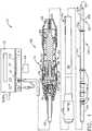
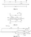
- FIG. 1illustrates one embodiment of an ultrasonic system 10 comprising a single-element end effector.
- One embodiment of the ultrasonic system 10comprises an ultrasonic signal generator 12 coupled to an ultrasonic transducer 14, a hand piece assembly 60 comprising a hand piece housing 16, and an ultrasonically actuatable single-element end effector 50 shown as an ultrasonically actuatable blade comprising a folded element 53.
- the ultrasonic transducer 14, which is known as a "Langevin stack"generally includes a transduction portion 18, a first resonator portion or end-bell 20, and a second resonator portion or fore-bell 22, and ancillary components. The total construction of these components is a resonator.
- An acoustic assembly 24includes the ultrasonic transducer 14, a nose cone 26, a velocity transformer 28, and a surface 30.
- proximal and distalare used herein with reference to a clinician gripping the hand piece assembly 60.
- end effectoris distal with respect to the more proximal hand piece assembly 60.
- spatial termssuch as “top” and “bottom” also are used herein with respect to the clinician gripping the hand piece assembly 60.
- surgical instrumentsare used in many orientations and positions, and these terms are not intended to be limiting and absolute.
- the distal end of the end-bell 20is connected to the proximal end of the transduction portion 18, and the proximal end of the fore-bell 22 is connected to the distal end of the transduction portion 18.
- the fore-bell 22 and the end-bell 20have a physical length determined by a number of variables, including the thickness of the transduction portion 18, the density and modulus of elasticity of the material used to manufacture the end-bell 20 and the fore-bell 22, and the resonant frequency of the ultrasonic transducer 14.
- the fore-bell 22may be tapered inwardly from its proximal end to its distal end to amplify the ultrasonic vibration amplitude as the velocity transformer 28, or alternately may have no amplification.
- a suitable vibrational frequency rangemay be about 20Hz to 120kHz and a well-suited vibrational frequency range may be about 30-100kHz.
- a suitable operational vibrational frequencymay be approximately 55.5 kHz, for example.
- the second resonator portion or the fore-bell 22may be folded to reduce the overall physical length of the fore-bell 22 while maintaining or increasing the acoustic length.
- Piezoelectric elements 32may be fabricated from any suitable material, such as, for example, lead zirconate-titanate, lead meta-niobate, lead titanate, barium titanate, or other piezoelectric ceramic material.
- Each of positive electrodes 34, negative electrodes 36, and the piezoelectric elements 32has a bore extending through the center.
- the positive and negative electrodes 34 and 36are electrically coupled to wires 38 and 40, respectively.
- the wires 38 and 40are encased within a cable 42 and electrically connectable to the ultrasonic signal generator 12 of the ultrasonic system 10.
- the ultrasonic transducer 14 of the acoustic assembly 24converts the electrical signal from the ultrasonic signal generator 12 into mechanical energy that results in primarily a standing acoustic wave of longitudinal vibratory motion of the ultrasonic transducer 14 and the end effector 50 at ultrasonic frequencies.
- the vibratory motion of the ultrasonic transducermay act in a different direction.
- the vibratory motionmay comprise a local longitudinal component of a more complicated motion of the tip of the ultrasonic system 10.
- a suitable generatoris available as model number GEN04, from Ethicon Endo-Surgery, Inc., Cincinnati, Ohio.
- the ultrasonic system 10is designed to operate at a resonance such that an acoustic standing wave pattern of predetermined amplitude is produced.
- the amplitude of the vibratory motion at any point along the acoustic assembly 24depends upon the location along the acoustic assembly 24 at which the vibratory motion is measured.
- a zero crossing in the vibratory motion standing waveis generally referred to as a node (i.e., where motion is zero), and a local absolute value maximum or peak in the standing wave is generally referred to as an antinode (i.e., where local motion is maximal).
- the distance between an antinode and its nearest nodeis one quarter wavelength ( ⁇ /4).
- the wires 38 and 40transmit an electrical signal from the ultrasonic signal generator 12 to the positive electrodes 34 and the negative electrodes 36.
- the piezoelectric elements 32are energized by the electrical signal supplied from the ultrasonic signal generator 12 in response to an actuator 44, such as a foot switch, for example, to produce an acoustic standing wave in the acoustic assembly 24.
- the alternating electrical signalcauses the piezoelectric elements 32 to expand and contract in a continuous manner along the axis of the voltage gradient, producing longitudinal waves of ultrasonic energy. The expansion and contraction produce small displacements alternating in direction resulting in large alternating compression and tension forces within the material.
- An ultrasonic transmission assembly 102includes the single-element end effector 50 coupled to an ultrasonic transmission waveguide 104.
- the ultrasonic energyis transmitted through the acoustic assembly 24 to the end effector 50 via a transmission component such as the ultrasonic transmission waveguide 104.
- the ultrasonic transmission waveguide 104may be preferably fabricated from a hollow core shaft constructed out of material that propagates ultrasonic energy efficiently, such as titanium alloy (i.e., Ti6Al4V) or an aluminum alloy, for example.
- the ultrasonic transmission waveguide 104may be formed as a solid core transmission waveguide.
- all components of the acoustic assembly 24are acoustically coupled to the end effector 50.
- the distal end of the ultrasonic transducer 14may be acoustically coupled at the surface 30 to the proximal end of the ultrasonic transmission waveguide 104 by a threaded connection such as a stud 48.
- the components of the acoustic assembly 24are preferably acoustically tuned such that the length of any assembly is an integral number of one-half wavelengths (n ⁇ /2), where the wavelength ⁇ is the wavelength of a pre-selected or operating longitudinal vibration drive frequency f d of the acoustic assembly 24. It is also contemplated that the acoustic assembly 24 may incorporate any suitable arrangement of acoustic elements.
- the end effector 50may have a length substantially equal to an integral multiple of one-half system wavelengths (n ⁇ /2).
- the bladecomprises a distal end 52, which coincides with the physical distal end of the folded element 53.
- the folded element 53comprises an acoustic distal end 55 located at an antinode in terms of displacement.
- the acoustic distal end 55is located at a point of maximum amplitude of the longitudinal ultrasonic vibration and the ultrasonic displacement is at a maximum.
- the distal end 52 of the end effector 50coincides with the distal end of the folded element 53 and may be disposed near an antinode to provide the maximum longitudinal excursion of the distal end 52.
- the corresponding proximal end 55 of the folded element 53may be disposed near a node.
- the distal end 52 of the end effector 50coincides with the distal end of the folded element 53 and may be disposed near a node to provide the minimum longitudinal excursion of the distal end 52.
- the corresponding proximal end 55 of the folded element 53may be disposed near an antinode to provide the maximum longitudinal excursion of the proximal end 55 of the folded element 53.
- the distal end 52 of the end effector 50coincides with the distal end of the folded element 53 and may be disposed between a node and an antinode to phase the longitudinal excursion of the distal end 52 accordingly.
- the distal end 52 of the blade 50coincides with the distal end of the folded element 53 and is disposed near a node to provide the minimum longitudinal excursion of the distal end 52.
- the corresponding proximal end 55 of the folded element 53is disposed near an antinode to provide the maximum longitudinal excursion of the proximal end 55 of the folded element 53.
- the proximal end 55 of the folded element 53may be configured to move in the range of, for example, approximately 10 to 500 microns peak-to-peak, and preferably in the range of about 30 to 150 microns at a predetermined vibrational frequency of 55kHz, for example.
- the end effector 50may be coupled to the ultrasonic transmission waveguide 104.
- the blade 50 and the ultrasonic transmission waveguide 104 as illustratedare formed as a single unit construction from a material suitable for transmission of ultrasonic energy. Examples of such materials include Ti6Al4V (an alloy of Titanium including Aluminum and Vanadium), Aluminum, Stainless Steel, or other suitable materials.
- the end effector 50may be separable (and of differing composition) from the ultrasonic transmission waveguide 104, and coupled by, for example, a stud, weld, glue, quick connect, or other suitable known methods.
- the length of the ultrasonic transmission waveguide 104may be substantially equal to an integral number of one-half wavelengths (n ⁇ /2), for example.
- the ultrasonic transmission waveguide 104may be preferably fabricated from a solid core shaft constructed out of material suitable to propagate ultrasonic energy efficiently, such as the titanium alloy discussed above (i.e., Ti6Al4V) or any suitable aluminum alloy, or other alloys, for example.
- material suitable to propagate ultrasonic energy efficientlysuch as the titanium alloy discussed above (i.e., Ti6Al4V) or any suitable aluminum alloy, or other alloys, for example.
- the ultrasonic transmission waveguide 104comprises a longitudinally projecting attachment post 54 at a proximal end to couple to the surface 30 of the ultrasonic transmission waveguide 104 by a threaded connection such as the stud 48.
- the ultrasonic transmission waveguide 104includes a plurality of stabilizing silicone rings or compliant supports 56 positioned at a plurality of nodes. The silicone rings 56 dampen undesirable vibration and isolate the ultrasonic energy from an outer sheath 58 ensuring the flow of ultrasonic energy in a longitudinal direction to the distal end 52 of the end effector 50 with maximum efficiency.
- the outer sheath 58protects a user of the ultrasonic surgical instrument 10 and a patient from the ultrasonic vibrations of the ultrasonic transmission waveguide 104.
- the sheath 58generally includes a hub 62 and an elongated tubular member 64.
- the tubular member 64is attached to the hub 62 and has an opening extending longitudinally therethrough.
- the sheath 58is threaded onto the distal end of the velocity transformer 28.
- the ultrasonic transmission waveguide 104extends through the opening of the tubular member 64 and the silicone rings 56 isolate the ultrasonic transmission waveguide 104 from the outer sheath 58.
- the outer sheath 58may be attached to the waveguide 104 with an isolator pin 114.
- the hole 116 in the waveguide 104may occur nominally at a displacement node.
- the waveguide 104may screw or snap onto the hand piece assembly 60 by the stud 48.
- the flat portions on the hub 62may allow the assembly to be torqued to a required level.
- the hub 62 of the sheath 58is preferably constructed from plastic and the tubular member 64 is fabricated from stainless steel.
- the ultrasonic transmission waveguide 104may incorporate a polymeric material surrounding it to isolate it from outside contact.
- the distal end of the ultrasonic transmission waveguide 104may be coupled to the proximal end of the single-element end effector 50 by an internal threaded connection, preferably at or near an antinode. It is contemplated that the end effector 50 may be attached to the ultrasonic transmission waveguide 104 by any suitable means, such as a welded joint or the like. Although the end effector 50 may be detachable from the ultrasonic transmission waveguide 104, it is also contemplated that the end effector 50 and the ultrasonic transmission waveguide 104 may be formed as a single unitary piece.
- the ultrasonic waveguide 104is implemented as an elongated transmission component and the end effector is implemented as a single-element end effector or the end effector 50 suitable to cut and/or coagulate tissue.
- the end effector 50may be symmetrical or asymmetrical.
- FIG. 2Aillustrates one embodiment of an ultrasonic system 1000 comprising a multi-element end effector.
- One embodiment of the ultrasonic system 1000comprises the ultrasonic generator 12 coupled to the ultrasonic transducer 14 previously described with reference to FIG. 1 .
- the ultrasonic transducer 14is coupled to clamping coagulating shears 1002 comprising an instrument housing 1004.
- the acoustic assembly 18delivers energy to a multi-element end assembly 1008 comprising an ultrasonic end effector 1016 shown in the form of an ultrasonically actuable blade.
- the acoustic assembly 18In order for the acoustic assembly 18 to deliver energy to the end effector 1016 portion of the multi-element end assembly 1008, all components of the acoustic assembly 18 are acoustically coupled to the ultrasonically active portions of the clamping coagulating shears 1002. Accordingly, the distal end of the ultrasonic transducer 14 may be acoustically coupled via the surface 30 to the proximal end of the ultrasonic transmission waveguide 104 by way of the threaded connection stud 48.
- the components of the acoustic assembly 18are preferably acoustically tuned such that the length of any assembly is an integral number of one-half wavelengths (n ⁇ /2), where the wavelength ⁇ is the wavelength of a pre-selected or operating longitudinal vibration drive frequency f d of the acoustic assembly 18.
- the acoustic assembly 18may incorporate any suitable arrangement of acoustic elements.
- the clamping coagulating shears 1002may be preferably attached to and removed from the acoustic assembly 18 as a unit.
- the proximal end of the clamping coagulating shears 1002preferably acoustically couples to the distal surface 30 of the acoustic assembly 18.
- the clamping coagulating shears 1002may be coupled to the acoustic assembly 18 by any suitable means.
- the clamping coagulating shears 1002preferably includes an instrument housing 1004 and an elongated member 1006.
- the elongated member 1006may be selectively rotated with respect to the instrument housing 1004 via the rotation knob 1010.
- the instrument housing 1004includes a pivoting handle portion 1028 and a fixed handle portion 1029.
- An indexing mechanism(not shown) is disposed within a cavity of the instrument housing 1004 and is preferably coupled or attached on an inner tube 1014 to translate movement of the pivoting handle portion 1028 to linear motion of the inner tube 1014 to open and close the multi-element end assembly 1008.
- the pivoting handle portion 1028includes a thumb loop 1030.
- a pivot pinis disposed through a first hole of the pivoting handle portion 1028 to allow pivoting.
- the thumb loop 1030 of the pivoting handle portion 1028is moved in the direction of arrow 1034, away from the instrument housing 1004, the inner tube 1014 slides distally away from the proximal end to pivot the clamp arm 1018 of the multi-element end assembly 1008 into an open position in the direction indicated by arrow 1020.
- the indexing mechanismslides the inner tube 1014 proximally away from the distal end to pivot the clamp arm 1018 of the multi-element end assembly 1008 into a closed position, as shown.
- the elongated member 1006 of the clamping coagulating shears 1002extends from the instrument housing 1004.
- the elongated member 1006preferably includes an outer member or outer tube 1012, an inner member or inner tube 1014, and a transmission component or ultrasonic transmission waveguide 104.
- the multi-element end assembly 1008includes a clamp arm 1018 (or clamp arm assembly) and the ultrasonic end effector 1016.
- the ultrasonic end effector 1016comprises folded elements as described in more detail below in FIGS. 4-21 .
- the ultrasonic blade 1016may be symmetrical or asymmetrical.
- the clamp arm 1018may comprise a tissue pad. Accordingly, the clamp arm 1018 may be referred to as a clamp arm assembly, for example.
- the clamp arm 1018may be configured to apply a compressive or biasing force to the tissue to achieve faster coagulation and cutting of the tissue.
- the clamp arm 1018is pivotally mounted about a pivot pin (not shown) to rotate in the direction indicated by arrow 1020.
- the clamp arm 1018may be configured to create a predetermined force distribution profile along the length (preferably along the active length) of the clamp arm 1018.
- the clamp arm 1018applies the predetermined force profile substantially over the entire active length of the end effector 1016.
- the clamp arm 1018may exert a minimum force at a point coinciding with an antinode of the end effector 1016.
- a normal forceis applied to the end effector 1016 by a reciprocating outer compression tube 1019 at or near the center of the clamp arm 1018.
- the force exerted by the clamp arm 1018increases from the center outwardly towards the proximal end and the distal end to either side of the center of the clamp arm 1018 towards the ends of the clamp arm 1018.
- the clamp arm 1018exerts a force distribution profile over the active length of the end effector 1016 that is ideally inversely proportional to the velocity amplitude displacement of the end effector 1016.
- the combination of the velocity of the end effector 1016 and the force exerted by the clamp arm 1018determines the force profile along the active length of the end effector 1016.
- Components of the ultrasonic surgical systems 10 and 1000may be sterilized by methods known in the art such as, for example, gamma radiation sterilization, Ethelyne Oxide processes, autoclaving, soaking in sterilization liquid, or other known processes.
- the end effector 50 and the ultrasonic transmission waveguide 104are illustrated as a single unit construction from a material suitable for transmission of ultrasonic energy as previously discussed (e.g., Ti6Al4V, Aluminum, Stainless Steel, or other known materials).
- the end effector 50may be separable (and of differing composition) from the ultrasonic transmission waveguide 104, and coupled by, for example, a stud, weld, glue, quick connect mechanism, or other known methods.
- the ultrasonic transmission assembly 1024 of the clamping coagulating shears 1002includes the multi-element end assembly 1008 coupled to the ultrasonic transmission waveguide 104.
- the length of the ultrasonic transmission waveguide 104may be substantially equal to an integral number of one-half system wavelengths (n ⁇ /2), for example.
- FIG. 2Billustrates one embodiment of the multi-element end assembly 1008.
- the multi-element end assembly 1008comprises an arcuate clamp arm 1018 (or clamp arm assembly) and the ultrasonic and effector 1016.
- the ultrasonic end effector 1016comprises folded elements as described in more detail below.
- the ultrasonic end effector 1016may be symmetrical or asymmetrical.
- a clamp arm assemblycomprises the clamp arm 1018 with a tissue pad 1021.
- the clamp arm 1018may be configured to apply a compressive or biasing force to tissue 1025 ( FIGS. 2C, 2D ) located between the tissue pad 1021 and the ultrasonic end effector 1016 to achieve faster coagulation and cutting of the tissue 1025.
- the compressive forcemay be applied by sliding the reciprocating outer compression tube 1019 over the clamp arm 1018.
- the clamp arm 1018is pivotally mounted about a pivot 1023 to rotate open in the direction indicated by arrow 1020 and rotate closed in the direction indicated by arrow 1027.
- the clamp arm 1018is configured to create a predetermined force distribution profile along the length of the clamp arm 1018 and the active length of the ultrasonic end effector 1016.
- FIGS. 2C and 2Dillustrate the clamp arm in various stages.
- FIG. 2Cillustrates the clamp arm 1018 in an open position ready to receive the tissue 1025 between the tissue pad 1021 and the end effector 1016.
- the reciprocating outer compression tube 1019is in a retracted position to enable the clamp arm 1018 to rotate in direction 1020 about the pivot 1023 to an open position.
- FIG. 2Dillustrates the clamp arm 1018 rotated about the pivot 1023 to rotate in direction 1027 to a closed position with the reciprocating outer compression tube 1019 partially slid in direction 1029 over the clamp arm 1018 applying a partial compressive force over the clamp arm 1018.
- FIG. 2Cillustrates the clamp arm 1018 in an open position ready to receive the tissue 1025 between the tissue pad 1021 and the end effector 1016.
- the reciprocating outer compression tube 1019is in a retracted position to enable the clamp arm 1018 to rotate in direction 1020 about the pivot 1023 to an open position.
- FIG. 2Dillustrates the clamp arm 10
- the reciprocating outer compression tube 1019is located in a fully extended position to apply a full compressive force against the clamp arm 1018. Accordingly, the clamp arm 1018 applies a predetermined force distribution profile along the length of the clamp arm 1018 and the active length of the end effector 1016.
- FIG. 3illustrates one embodiment of a connection union/joint 70 for an ultrasonic instrument.
- the connection union/joint 70is located between the acoustic assembly 24 and an ultrasonic transmission component such as the ultrasonic transmission waveguide 104, for example.
- the connection union/joint 70may be formed between an attachment post 54 of the ultrasonic transmission waveguide 104 and the surface 30 of the velocity transformer 28 located at the distal end of the acoustic assembly 24.
- the proximal end of the attachment post 54comprises a female threaded substantially cylindrical recess 66 to receive a portion of the threaded stud 48 therein.
- the distal end of the velocity transformer 28also may comprise a female threaded substantially cylindrical recess 68 to receive a portion of the threaded stud 48.
- the recesses 66 and 68are substantially circumferentially and longitudinally aligned.
- the studmay be formed as an integral component of the end of the ultrasonic transducer 14 shown in FIG. 1 .
- the threaded stud and the velocity transformermay be formed as a single unit construction with the stud projecting from a distal surface of the velocity transformer at the distal end of the acoustic assembly.
- the studis not a separate component and does not require a recess in the end of the transducer.
- the letter “A”denotes the location of a displacement antinode and the letter “N” denotes the location of a displacement node.
- the distance between an antinode “A” and its nearest node “N”is one quarter wavelength ( ⁇ /4).
- One quarter wavelength ( ⁇ /4)is primarily determined by the frequency and speed of sound in the material. The speed of sound in most metals suitable for ultrasonic components is nominally 5,000 meters per second. Unless otherwise stated, in the embodiments described herein the wavelength is determined at an excitation frequency of 55.5 kHz where the wavelength is approximately 9.09 cm (3.58 inches) and one quarter wavelength ( ⁇ /4) is approximately 2.25 cm (0.886 inches).
- the quarter wavelengthis approximately 2.20 cm (0.866 inches).
- Other materials that may lead to longer or shorter wavelengthsmay be employed.
- the active length in Ti6Al4Vis nominally approximately 0.6 inches ( ⁇ 15mm).
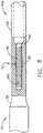
- FIG. 4is a schematic diagram of one embodiment of a hollow tubular end effector 400.
- FIG. 4Ais a longitudinal cross-sectional view of the end effector 400.
- FIG. 4Bis a cross-sectional view of the end effector 400 taken along line 4B-4B.
- a characteristic ultrasonic displacement curve 420 for the end effector 400is graphically illustrated in FIG. 7 and is described in more detail below.
- the end effector 400comprises a body 406 having a proximal end 402, a distal end 404, and a cylindrical outer surface.
- the end effector 400is described as a reference to facilitate understanding of the operation of the end effectors with folded elements in the embodiments shown in FIGS. 5 and 6 .
- the end effector 400has a physical length "L" of three quarter wavelengths (3 ⁇ /4).
- the end effector 400may be formed of Ti6Al4V excited at a frequency of 55.5 kHz.
- one quarter wavelength ( ⁇ /4)is approximately 2.20 cm (0.866 inches).
- Other materials that may provide longer or shorter wavelengthsmay be employed.
- the active length in Ti6Al4Vis nominally approximately 0.6 inches ( ⁇ 15mm).
- the proximal end 402 of the end effector 400is located at the left side and the distal end 404 of the end effector 400 is located at the right side of the end effector 400.
- the first quarter wavelengthextends between the first node N1 and the first antinode A1;
- the second quarter wavelengthextends between the first antinode A1 and the second node N2;
- the third quarter wavelengthextends between the second node N2 and the second antinode A2.
- the first node N1is located at the proximal end 402 and the second antinode A2 is located at the distal end 404.
- the proximal end 402 of the end effector 400is configured to couple to the velocity transformer 28 at the surface 30 as shown in FIGS. 1 and 2A .
- the proximal end 402may be connected to or be a part of an additional transmission waveguide extending further in the proximal direction.
- the end effector 400may be extended proximally by one quarter wavelength ( ⁇ /4) so that the proximal end 402 coincides with an antinode.
- the velocity transformer 28 and the end effector 400may be joined together at their respective antinodes and the system frequency remains near the desired nominal value.
- the nominal frequencyis 55.5 kHz, for example.
- the added proximal quarter wavelengthmay have the same area as the outside parallel path (i.e., extended proximally by a quarter wave length). In which case, there is no gain. If the proximal segment has an increased area, then there will be amplitude gain due to the decrease in area relative to end effector 400 this represents.
- the end effector 400may include gain, attenuation, and other features to achieve a desired performance as an ultrasonic surgical instrument operating at 55.5 kHz, for example. As shown in FIG.
- the distal end 404coincides with the second antinode A2 and, therefore, the distal end 404 is a point of maximum amplitude of the longitudinal ultrasonic vibration and the ultrasonic displacement is at a maximum.
- the proximal end 402coincides with the first node N1 and, therefore, the proximal end 402 is a point of minimum amplitude of the longitudinal ultrasonic vibration and the ultrasonic displacement is at a minimum.
- FIG. 5is a schematic diagram of one embodiment of an end effector 408 comprising a folded element 418 defining a parallel acoustic path.
- FIG. 5Ais a longitudinal cross-sectional view of the end effector 408.
- FIG. 5Bis a cross-sectional view of the end effector 408 taken along line 5B-5B.
- the end effector 408is suitable for use in the embodiment of the single-element end effector ultrasonic system 10 shown in FIG. 1 .
- the end effector 408may be suitably adapted for use in the embodiment of the multi-element end effector system 1000 shown in FIG. 2A .
- a characteristic ultrasonic displacement curve 430 for the end effector 408is graphically illustrated in FIG.
- the end effector 408is a hollow tube ultrasonic transmission line comprising a body 410 having a proximal end 414 and a distal end 416 with a folded element 412 coupled to (e.g., folded at) the distal end 416 at the second node N2.
- the folded element 412extends proximally from the second node N2 located at the distal end 416 towards the proximal end 414 into a hollow portion 413 of the end effector 408 to the first antinode A1.
- An acoustic distal end 418 of the folded element 412terminates at the first antinode A1, where the first antinode A1 coincides with the second antinode A2.
- the first and second antinodes A1, A2coincide when an end effector is folded at a node N and the length of the folded element is one quarter wavelength ( ⁇ /4). If the length of the folded element 412 is greater than or less than one quarter wavelength ( ⁇ /4), the first and second antinodes A1, A2 will not coincide. For example, if the fold is made between a node (N) and an antinode (A), the first and second antinodes A1, A2 will not coincide even if the length of the folded element 412 is one quarter wavelength ( ⁇ /4).
- the folded element 412extends parallel to the longitudinal axis and to an outer surface of the body 410 of the end effector 408.
- the folded element 412 and the outer body of 410 of the end effector 408define a parallel acoustic path 417 spanning the length of the folded element 412.
- the parallel acoustic path 417extends between the first antinode A1 and the second node N2.
- the folded element 412is a solid rod. Over its length, the cross-sectional area of the folded element 412 is substantially equal to the longitudinal cross-sectional area of the end effector 408.
- the folded element 412forms the distal quarter wavelength ( ⁇ /4) of the end effector 408.
- the embodimentsare not limited in this context.
- the proximal end 414 of the end effector 408may be configured to couple to the velocity transformer 28 at the surface 30 as shown in FIGS. 1 and 2A .
- the proximal end 414may be connected to or may form a portion of an ultrasonic transmission waveguide extending further in the proximal direction.
- the end effector 408may be extended proximally by one quarter wavelength ( ⁇ /4) so that the proximal end 414 coincides with an antinode. Accordingly, the velocity transformer 28 and the end effector 408 may be joined together at their respective antinodes and the system frequency remains near the desired nominal value.
- the nominal frequencyis 55.5 kHz, for example.
- the added proximal quarter wavelengthmay have the same area as the outside parallel path (i.e., extended proximally by a quarter wave length). In which case, there is no gain. If the proximal segment has an increased area, then there will be amplitude gain due to the decrease in area with respect to 410 this represents.
- the end effector 408may include gain, attenuation, and other features to achieve a desired performance as an ultrasonic surgical instrument operating at 55.5 kHz, for example.
- the end effector 408comprises a free distal end 416 that coincides with the second node N2.
- the distal end 416is a region of minimum amplitude displacement.
- the acoustic distal end 418is located at a proximal end of the folded element 412.
- the acoustic distal end 418coincides with the first and second antinodes A1, A2 in terms of displacement.
- the acoustic distal end 418is a region of maximum amplitude displacement.
- the external portion of the end effector 408has a maximum displacement at its center located at the first antinode A1. Because the amplitude falls off symmetrically on either side of the first antinode A1, the active length is approximately 1.2 inches ( ⁇ 30mm). This is double the active length of approximately 0.6 inches ( ⁇ 15mm) of the end effector 400 illustrated in FIG. 4 .
- the active lengthis measured from the second antinode A2 at the distal end 404 where the maximum amplitude displacement occurs to a point where the amplitude drops of to 50% of maximum somewhere between the second antinode A2 and the second node N2.
- the physical length of the folded element 412may be greater than or less than one quarter wavelength ( ⁇ /4), or may be less than an integer multiple thereof (n ⁇ /4), such that the ultrasonic amplitude displacement of the acoustic distal end 418 of the end effector 408 can be phased between maximum displacement and minimum displacement by suitably selecting the length of the folded element 412.
- the length of the end effector 408may be greater than or less than any number of quarter wavelengths ( ⁇ /4). It will be appreciated by those skilled in the art that in the various embodiments described herein, the length L1 of the end effector 408 is longer than the length of the folded segment 412.
- the combined length of the end effector 408 and the folded element 412may be any suitable number of quarter wavelengths ( ⁇ /4).
- a particularly beneficial position for locating the foldis at in the region between the first antinode A1 and the second node N2 where the displacement amplitude drops off to 50% of maximum.
- the distal end 416occurs at the limit of the active length.
- the displacement amplituderemains above the minimum effective amplitude (>50% of maximum) to a region beyond the first antinode A1.
- the amplitudebegins to drop below the desired 50% amplitude level.
- the active length for end effectors designed with titanium (Ti) operating at 55.5 kHzmay be extended to approximately 1.2 inches ( ⁇ 30mm).
- the longitudinal extension of the end effector 408retains the ultrasonic displacement characteristics of that location without the fold.
- the foldis located at the second node N2, at the distal end 416, and the folded element 412 extends proximally one quarter wavelength ( ⁇ /4) from the distal end 416 to the first and second antinodes A1, A2, which coincide with the acoustic distal end 418.
- the displacement pattern and locations of the first and second nodes N1, N2remain the same along the longitudinal length of the end effector 408.
- the second node N2remains a node, e.g., minimum or no displacement amplitude, even though it "presents" a free-end. Accordingly, the distal end 416 of the end effector 408 has substantially zero displacement and remains dull even when it is ultrasonically activated. This feature may be desirable in certain procedures to protect tissue that may come into contact with or may be in proximity to the distal end 416. Otherwise, an active distal end may create a surgical window or -otomy through the tissue it comes into contact with.
- -otomyrefers to a combining form meaning "cutting, incision" of tissue or an organ, "excision" of an object, as specified by the initial element.
- FIG. 6is a schematic diagram of one embodiment of an end effector 438 comprising a folded element 442 defining a parallel acoustic path.
- FIG. 6Ais a longitudinal cross-sectional view of the end effector 438.
- FIG. 6Bis a cross-sectional view of the end effector 438 taken along line 6B-6B.
- the end effector 438is suitable for use in the embodiment of the single-element end effector ultrasonic system 10 shown in FIG. 1 .
- the end effector 438may be suitably adapted for use in the embodiment of the multi-element end effector system 1000 shown in FIG. 2A .
- the end effector 438will now be described with reference to FIGS. 6, 6A, and 6B .
- the end effector 438is a substantially solid ultrasonic transmission line comprising a body 440 having a proximal end 444 and a distal end 446 and the folded element 442 coupled to the distal end 446 at the second node N2.
- the end effector 438comprises a slot 445 formed in a distal end of the solid portion 443 thereof.
- the folded element 442extends proximally from the second node N2 located at the distal end 446 into the slot 445 parallel to the longitudinal axis towards the proximal end 444 to the first antinode A1.
- An acoustic distal end 448 of the folded element 442terminates at the first antinode A1, where the first antinode A1 coincides with the second antinode A2.
- the first and second antinodes A1, A2coincide when an end effector is folded at a node N and the length of the folded element is one quarter wavelength ( ⁇ /4). If the length of the folded element 442 is greater than or less than one quarter wavelength ( ⁇ /4), the first and second antinodes A1, A2 will not coincide. Also, if the fold is made between a node (N) and an antinode (A), the first and second antinodes A1, A2 will not coincide even if the length of the folded element 442 is one quarter wavelength ( ⁇ /4).
- the folded element 442extends parallel to the longitudinal axis and to an outer surface of the body 440 of the end effector 408.
- the folded element 442 and an external surface of the body 440 of the end effector 438define a parallel acoustic path 447 spanning the length of the folded element 442.
- parallel acoustic path 447extends between the first antinode A1 and the second node N2.
- the folded element 442is configured as a rod of rectangular cross section extending in the slot 445 formed within the end effector 438.
- the end effector 438has a physical length "L1" of two quarter wavelengths (2 ⁇ /4).
- the folded element 442may have a physical length of approximately one quarter wavelength ( ⁇ /4). Over its length, the longitudinal cross-sectional area of the folded element 442 is substantially equal to the longitudinal cross-sectional area of the end effector 438.
- the embodimentsare not limited in this context.
- the proximal end 444 of the end effector 438is configured to couple to the velocity transformer 28 at the surface 30 as shown in FIGS. 1 and 2A .
- the proximal end 444may be connected to or may form a portion of an additional transmission waveguide extending further in the proximal direction.
- the end effector 438may be extended proximally by one quarter wavelength ( ⁇ /4) so that the proximal end 444 coincides with an antinode. Accordingly, the velocity transformer 28 and the end effector 438 may be joined together at their respective antinodes and the system frequency remains near the desired nominal value.
- the nominal frequencyis 55.5 kHz, for example.
- the added proximal quarter wavelengthmay have the same area as the outside parallel path (i.e., extended proximally by a quarter wave length). In which case, there is no gain. If the proximal segment has an increased area, then there will be amplitude gain due to the decrease in area with respect to 438 this represents.
- the end effector 438may include gain, attenuation, and other features to achieve a desired performance as an ultrasonic surgical instrument operating at 55.5 kHz, for example.
- the end effector 438comprises a free distal end 446 that coincides with the second node N2.
- the distal end 446is a region of minimum amplitude displacement.
- the acoustic distal end 448is located at a proximal end of the folded element 442.
- the acoustic distal end 448coincides with the first and second antinodes A1, A2 in terms of displacement.
- the acoustic distal end 448is a region of maximum amplitude displacement.
- the external portion of the end effector 438has a maximum displacement at its center located at the first antinode A1. Because the amplitude falls off symmetrically on either side of the first antinode A1, the active length is approximately 1.2 inches ( ⁇ 30mm). This is double the active length of approximately 0.6 inches ( ⁇ 15mm) of the end effector 400 illustrated in Fig. 4 .
- the physical length of the folded element 442may be greater than or less than one quarter wavelength ( ⁇ /4), or maybe less than an integer multiple thereof (n ⁇ /4), such that the ultrasonic displacement of the acoustic distal end 448 of the end effector 438 can be phased between maximum displacement and minimum displacement by suitably selecting the length of the folded element 442.
- the length of the end effector 438may be greater than or less than any number of quarter wavelengths ( ⁇ /4). It will be appreciated by those skilled in the art that in the various embodiments described herein, the length L1 of the end effector 438 is longer than the length of the folded element 442.
- the combined length of the end effector 438 and the folded element 442may be any suitable number of quarter wavelengths ( ⁇ 4).
- a particularly beneficial position for locating the foldis at in the region between the first antinode A1 and the second node N2 where the displacement amplitude drops off to 50% of maximum.
- the distal end 446occurs at the limit of the active length.
- the displacement amplituderemains above the minimum effective amplitude (>50% of maximum) to a region beyond the first antinode A1.
- the amplitudebegins to drop below the desired 50% amplitude level.
- the active length for end effectors designed with titanium (Ti) operating at 55.5 kHzmay be extended to approximately 1.2 inches ( ⁇ 30mm).
- the longitudinal extension of the end effector 438retains the ultrasonic displacement characteristics of that location without the fold.
- the foldis located at the second node N2, at the distal end 446, and the folded element 442 extends proximally one quarter wavelength ( ⁇ /4) from the distal end 446 to the first and second antinodes A1, A2, which coincide with the acoustic distal end 448.
- the displacement pattern and locations of the first and second nodes N1, N2remain the same along the longitudinal length of the end effector 438.
- the second node N2remains a node, e.g., minimum or no displacement amplitude, N2 even though it "presents" a free-end. Accordingly, the distal end 446 of the end effector 438 has substantially zero displacement and remains dull even when it is ultrasonically active. This feature may be desirable in certain procedures to protect tissue that may come into contact with or may be in proximity to the distal end 446. Otherwise, an active distal end may create a surgical window or -otomy through the tissue it comes into contact with.
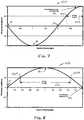
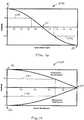
- FIG. 7graphically illustrates a characteristic ultrasonic displacement curve 420 for the end effector 400 shown in FIGS. 4, 4A, and 4B .
- the displacement curve 420illustrates displacement in terms of ultrasonic amplitude along the vertical axis and quarter wavelengths ( ⁇ /4) along the horizontal axis.
- the ultrasonic amplitude of the displacement curve 420is approximately zero at the proximal end 402, which is the location of the first node N1.
- the first antinode A1is located one quarter wavelength ( ⁇ /4) from the proximal end 402.
- the ultrasonic amplitude of the displacement curve 420 at the first (e.g., proximal) antinode A1is -1 (-100%), meaning that the first antinode A1 is a location of maximum or peak ultrasonic displacement.
- the negative signrepresents the phase of the ultrasonic displacement at the first antinode A1 relative to the second (e.g., distal) antinode A2.
- the displacementmay be characterized as temporal oscillations in accordance with equation (1) above.
- the second node N2is located two quarter wavelengths (2 ⁇ /4) from the proximal end 402.
- the ultrasonic amplitude of the displacement curve 420 at the second node N2is zero.
- the second antinode A2is located at the distal end 404, which is located at a distance of three quarter wavelengths (3 ⁇ /4) from the proximal end 402.
- the amplitude of the displacement curve 420 at the second antinode A2is +1 (+100%), meaning that the second antinode A2 is a location of maximum or peak ultrasonic displacement.
- the active length of an ultrasonic instrumentgenerally may be defined as the distance from an active distal end of an end effector (where ultrasonic displacement is at a maximum) to a proximal location along the end effector where the ultrasonic displacement amplitude drops below a predetermined level, such as 50%, as approaching a node (where ultrasonic displacement is at a minimum) is approached.
- the end effector 400has an active length 422 that extends from the second antinode A2 located at the distal end 404 to a proximal location 424, where the ultrasonic displacement drops to +0.5 (+50%), or one half-peak level.
- the proximal location 424is located within the third quarter wavelength portion.
- the active length 422is approximately 0.65 quarter wavelengths or approximately 0.6 inches ( ⁇ 15mm).
- FIG. 8graphically illustrates an ultrasonic displacement curve 430 for the end effectors 408 and 438 shown in FIGS. 5, 5A, 5B , and FIGS. 6, 6A, 6B respectively.
- the displacement curve 430illustrates displacement in terms of ultrasonic amplitude along the vertical axis and quarter wavelengths ( ⁇ /4) along the horizontal axis.
- the ultrasonic amplitude of the displacement curve 430is approximately zero at the proximal end 414, which is the location of the first node N1.
- the first antinode A1is located one quarter wavelength ( ⁇ 4) from the proximal end 414.
- the ultrasonic amplitude of the displacement curve 430 at the first (e.g., proximal) antinode A1is +1 (+100%), meaning that the first antinode A1 is a location of maximum or peak ultrasonic displacement.
- the second node N2is located two quarter wavelengths (2 ⁇ /4) from the proximal end 414.
- the amplitude of the displacement curve 430 at the second (e.g., distal) node N2also is approximately zero. As shown in FIG.
- the end effector 408, 438has an active length 432 defined as the distance from a proximal location 434a, where the ultrasonic displacement curve 430 crosses above an ultrasonic amplitude of +0.5 (+50%), e.g., one half-peak level, to a distal location 434b, where the ultrasonic displacement curve 430 crosses below an ultrasonic amplitude of +0.5 (+50%), e.g., one half-peak level.
- the active length 432is approximately 1.3 quarter wavelengths or approximately 1.2 inches ( ⁇ 30mm).
- the peak displacement of the ultrasonic displacement curve 430occurs in the middle of the active length 432 at the antinode A1. It decreases to either side of the middle as the first and second end nodes N1, N2 are approached.
- the active length of the end effector 408, 438is thus approximately double that of the end effector 400 shown in FIG. 4 .
- FIG. 9illustrates a schematic diagram of one embodiment of a multi-element end effector 450 comprising the folded element 412 defining a parallel acoustic path 417.
- the multi-element end effector 450is suitable for use in the embodiment of the multi-element end effector ultrasonic system 1000 shown in FIG. 2A .
- the multi-element end effector 450comprises the end effector 408 operatively coupled to a clamp arm 452.
- the clamp arm 452may comprise a tissue pad 454.
- the ultrasonic amplitude displacement profile of the active length region of the end effector 408requires a predetermined force profile by the clamp arm 452.
- the ultrasonic amplitude displacementdecreases moving proximally from the antinode (A) towards the node (N).
- the displacement curve 430is maximum in a center region at the first antinode A1 and decreases symmetrically away from the centrally located antinode A1 towards the first and second nodes N1, N2 to either side of the antinode A1.
- the clamp arm 452may be configured to apply a force against the end effector 408 that is inversely proportional to the displacement curve 430 ( FIG. 8 ) of the end effector 408.
- the force distribution profile produced by the clamp pad/arm 452is the inverse of the amplitude curve so that the product of ultrasonic velocity of the end effector 408 and the force against it remains nominally constant over the active length region. In both concepts the normal force would be applied at the center of the clamp arm/pad.
- the clamp arm 452may be configured as a leaf-spring like mechanism to apply a normal force 456 at the first antinode A1 of the end effector 408, a normal force 457a at a proximal end of the end effector 408, and a normal force 457b at a distal end of the end effector 408.
- the clamp arm 452may comprise a leaf spring mechanism in the form of a slender arc-shaped length of spring steel of rectangular cross-section.
- FIG. 10illustrates a schematic diagram of one embodiment of a multi-element end effector 460 comprising the folded element 412 defining a parallel acoustic path.
- the multi-element end effector 460is suitable for use in the embodiment of the multi-element end effector ultrasonic system 1000 shown in FIG. 2A .
- the multi-element end effector 460comprises the end effector 408 operatively coupled to a hinged clamp arm assembly 462.
- the hinged clamp arm assembly 462comprises first and second tissue pad members 464a, b.
- the hinged clamp arm assembly 462may comprise a hinge configuration in the form of a first member 462a and a second member 462b coupled at a pivot point 468.
- the first and second members 462a, bare adapted to receive the corresponding first and second tissue pad members 464a, b.
- a spring 470applies a force to the hinged first and second clamp arm members 462a, b.
- the spring 470may be a torsional spring, flat spring, or any other suitable type of spring known in the art.
- the hingealso may be a living hinge where there is a central segment that is thinned out relatively to the longer segments of the clamp arm on either side. Those skilled in the art will appreciate that living hinges are well known in the field of mechanical design.
- the hinged clamp arm assembly 462may be configured as a hinge-like mechanism comprising a pivot point 468 to apply the greatest forces 467a, b at the ends of the active length region of the end effector 408 with sufficient force 466 at the center located at the first antinode A1.
- the forces 466 and 467a, b applied by the clamp arm 462 against the end effector 408are ideally inversely proportional to the displacement curve 430 graphically illustrated in FIG. 8 .
- FIG. 11illustrates a longitudinal cross-sectional view of one embodiment of an extendable tubular end effector 478.
- the end effector 478is suitable for use in the embodiment of the single-element end effector ultrasonic system 10 shown in FIG. 1 .
- the end effector 478may be suitably adapted for use in the embodiment of the multi-element end effector system 1000.
- the end effector 478comprises a body 480 having a proximal end 484 and a distal end 486 and a folded element 482 slideably coupled to the body 480.
- the end effector 478is a tubular end effector shown in the extended configuration.
- the folded element 482is slideably moveable in the directions indicated by arrows 490a, b along the longitudinal axis. Once it is extended, the folded element 482 is locked in place to act as a suitable ultrasonic transmission element. To place the end effector 478 in the extended configuration the folded element 482 is extended in the direction indicated by arrow 490a by any suitable techniques.
- the folded element 482is configured as a cylindrical element.
- the cylindrical folded element 482may be slid forwardly toward the distal end.
- Several mechanismsmay be employed to slide the folded element 482.
- the folded element 482may be configured with a male threaded portion at a proximal end to engage a matching female threaded portion formed in the distal end of the 478.
- the folded element 482is “locked” into position with sufficient force for suitable transmission of the ultrasonic energy to either the distal end 488 in the extended configuration or the acoustic distal end 489 in the retracted configuration.
- Additional mechanismsmay be included to slide an exterior sheath to protect the tissue from the vibration in the proximal two quarter wavelength segments and expose the tissue to the distal quarter wavelength.
- a mechanismmay be provided to slide the symmetric clamp arm/pad assemblies 452, 462 ( FIGS. 9, 10 ) distally to be used with only the distal quarter wavelength.
- the extendable end effector 478has a physical length L1 of two quarter wavelengths (2 ⁇ /4).
- the end effector 478has a physical length of approximately two quarter wavelength (2 ⁇ /4) and the folded element 482 has a length L3 of approximately one quarter wavelength ( ⁇ /4).
- the folded element 482forms the distal quarter wavelength ( ⁇ /4) of the end effector 478.
- the combined length of the end effector 478 and the folded element 482has a physical length L2 of approximately three quarter wavelengths (3 ⁇ /4).
- the distal end 486coincides with the second node N2.
- the free distal end 486 at the node N2 portion of the end effector 478has nominally zero displacement and provides a dull surface to avoid damage to neighboring tissues when use the active length of 480.
- the folded element 482extends from the second node N2 to the second antinode A2.
- a distal end 488 of the folded element 482is a region of maximum amplitude displacement coinciding with the second antinode A2.
- the distal end 488may be used to create a surgical window, -otomy, or back-cutting.
- the folded element 482may be retracted in the direction indicated by arrow 490b by any suitable techniques. In the retracted configuration (shown in phantom), the folded element 482 is slideably located into a hollow portion 483 of the end effector 478.
- the end effector 478comprises an acoustic distal end 489 located at the first antinode A1 in terms of displacement and defines a parallel acoustic path 487 with an outer surface of the body 480 of the end effector 478.
- the parallel acoustic path 487extends between the first antinode A1 and the second node N2.
- the acoustic distal end 489is a region of maximum amplitude displacement. Because the acoustic distal end 489 is located within the hollow portion 483, unintended contact with adjacent tissue at high amplitude is avoided.
- the distal end 488may be suitable for other surgical procedures such as creating surgical windows, -otomies, and/or back-cutting. During a back-cutting procedure, the surgeon may employ the distal end 488 active tip of the end effector 478 to divide tissues along planes.
- the proximal end 484 of the extendable end effector 478is configured to couple to the velocity transformer 28 at the surface 30 as shown in FIGS. 1 and 2A , for example.
- the proximal end 484may be connected to or may form a portion of an additional transmission waveguide extending further in the proximal direction.
- the end effector 478may be extended proximally by one quarter wavelength ( ⁇ /4) so that the proximal end 484 coincides with an antinode. Accordingly, the velocity transformer 28 and the end effector 478 may be joined together at their respective antinodes and the system frequency remains near the desired nominal value.
- the nominal frequencyis 55.5 kHz, for example.
- the added proximal quarter wavelengthmay have the same area as the outside parallel path (i.e., extended proximally by a quarter wave length). In which case, there is no gain. If the proximal segment has an increased area, then there will be amplitude gain due to the decrease in area with respect to 478 this represents.
- the end effector 478may include gain, attenuation, and other features to achieve a desired performance. In the retracted configuration, the end effector 478 comprises a free distal end 486 that coincides at the second node N2 in terms of amplitude displacement.
- the distal end 486is a region of minimum amplitude where the longitudinal ultrasonic vibration and the ultrasonic displacement is at a minimum.
- the extendable end effector 478also comprises a distal end 488 located at a second antinode A2.
- the distal end 488is therefore a region of maximum amplitude where the longitudinal ultrasonic vibration and the ultrasonic displacement is at a maximum. Accordingly, the distal end 488 of the folded element 482 may be employed to effect tissue.
- the folded element 482may be folded at a displacement region located between a node "N” and an antinode "A" such that the ultrasonic displacement of the acoustic distal end 488 may be phased between maximum displacement and minimum displacement as shown below in FIG. 20 .
- the length of the folded parallel path 707 shown in FIG. 20is greater than a quarter wavelength (> ⁇ /4).
- the physical length of the folded element 482may be less that one quarter wavelength ( ⁇ /4), or less than an integer multiple thereof (n ⁇ /4), such that the ultrasonic displacement of the distal end 488 is phased between maximum displacement and minimum displacement when the folded element 482 is retracted.
- the combined length L2 of the end effector 478 and the extended folded element 482may be any suitable number of wavelengths ( ⁇ ).
- the extendable end effector 478retains the ultrasonic displacement characteristics of that location without the fold.
- the foldis located at the second node N2 and the folded element 482 is extendable one quarter wavelength ( ⁇ /4) from the distal end 486 coinciding with the second node N2 to the extended distal end 488 coinciding with the second antinode A2.
- the second node N2remains the second node N2 and "presents" a free-end.
- FIG. 12illustrates a schematic diagram of one embodiment of a rotatable end effector 500.
- the extendable end effector 500is suitable for use in the embodiment of the single-element end effector ultrasonic system 10 shown in FIG. 1 .
- the end effector 500may be suitably adapted for use in the embodiment of the multi-element end effector system 1000.
- the end effector 500comprises a body 501 having a proximal end 504 and a distal end 506 and a folded element 502 rotatably coupled to the body 501.
- the end effector 500is a slotted rectangular bar that comprises a solid elongated element 512 and a slot 519 formed at the distal end.
- the folded element 502is rotatably moveable about a pivot axis 510 at a distal end 506 of the elongated element 512. To locate the end effector 500 in the extended configuration the folded element 502 may be rotated outwardly about the axis 510 in the direction indicated by arrow 514a. In the extended configuration the folded element 502 extends from the second node N2 to the second antinode A2 and behaves as a conventional ultrasonic instrument with maximum ultrasonic displacement occurring at the distal end 508 coinciding with the second antinode A2.
- the folded element 502may be rotated inwardly about the axis 510 in the direction indicated by arrow 514b.
- the distal end 508 of the end effector 500also behaves as the acoustic distal end 509 located at the first antinode A1 in terms of displacement and forms a parallel acoustic path 517 with an outer surface of the body 501 of the end effector 500.
- the distal end 508is a region of maximum amplitude where the longitudinal ultrasonic vibration and the ultrasonic displacement is at a maximum.
- the distal end 508 of the folded element 502may be configured to effect tissue.
- the pivot axis 510may be implemented as a hinge mechanism.
- FIG. 13is a schematic diagram of a straight elongated end effector 520.
- the length L4 of the end effector 520is two quarter wavelengths (2 ⁇ /4).
- the end effector 520extends from a proximal end 522 located at a first antinode A1, through a node N1, and ends at a second antinode A2 at the distal end 524.
- the ultrasonic displacement curve of the end effector 520is graphically illustrated in FIG. 16 .
- FIG. 14is a schematic diagram of one embodiment of an end effector 530 comprising a folded element defining a parallel acoustic path 533.
- the end effector 530may be formed by folding the straight elongated rod end effector 520 ( FIG. 13 ) at the location of the node N1.
- the end effector 530comprises a first element 532 extending from the first antinode A1 to the node N1 and a folded second element 534 that is folded back towards the proximal end to define the parallel acoustic path 533.
- the folded second element 534may be substantially parallel with the first element 532 and extends from the node N1 to the second antinode A2.
- the proximal end 536may be adapted and configured to couple to the velocity transformer 28 at the surface 30 as shown in FIGS. 1 and 2A , for example.
- the length of the proximal end 536may be extended by additional quarter wavelengths to allow the end effector 530 and the velocity transformer 30 to be joined at corresponding antinodes.
- the proximal end 536may be connected to or may form a portion of an additional transmission waveguide extending further in the proximal direction.
- the end effector 530comprises an acoustic distal end 538 that is substantially aligned with the second antinode A2 and is configured to effect tissue (e.g., cut and/or coagulate).
- the first and second elements 532, 534may be coupled by a substantially rigid third member 540.
- FIG. 15is a schematic diagram of one embodiment of an end effector 550 comprising a folded element 562 defining a parallel acoustic path 556.
- the end effector 550may be formed by folding a distal segment of the straight end effector 520 ( FIG. 13 ) at the location coinciding with the node N1 to define a folded element 552 in the form of a hook.
- the end effector 550comprises an elongated portion 554 extending from a proximal end 558 to a first antinode A1 and a folded element 552 extending from the first antinode A1 to the node N1.
- the folded element 552comprises a first element 560 extending from the first antinode A1 to the node N1 and a folded second element 562 that extends from the node N1 to the second antinode A2.
- the folded second element 562is folded back towards the proximal end to form a parallel acoustic path 553.
- the folded second element 562is substantially parallel with the first element 560.
- the end effector 550comprises a proximal end 558 configured to couple to the velocity transformer 28 at the surface 30 as shown in FIGS. 1 and 2A .
- the proximal end 558may be connected to or may form a portion of an additional transmission waveguide extending further in the proximal direction.
- the end effector 550comprises an acoustic distal end 564 that is located substantially aligned with the second antinode A2 and is configured to effect tissue (e.g., cut and/or coagulate) located in an opening 566 defined between the first and second elements 560, 562.
- tissuee.g., cut and/or coagulate
- the folded element 552 or hookmay be formed by bending a distal segment of a straight elongated rod ultrasonic transmission waveguide.
- the elongated portion 554 and/or the folded element 552may incorporate balancing features to minimize transverse vibration in the proximal elongated portion 554. Examples of ultrasonic surgical instruments with balanced end effector features are disclosed in U.S. Pat. Nos.
- tissuemay be located in the opening 566 defined between the first and second elements 560, 562.
- the folded element 552may be pulled through a portion of tissue to continuously transect and coagulate the tissue.
- the folded element 552may be employed as a fixed blade such as for mesentery takedown, for example.
- the first element 560 and the second element 562may be located at a predetermined angle relative to each other at a distal end 568.
- the angled featuremay be suitable to increase the nip pressure as the tissue is forced towards the node N1 at the distal end 568 during a transecting and coagulating procedure.
- the folded portion 552may be employed as a shear. In such an embodiment, however, the relative ultrasonic displacement amplitudes of each of the first and second elements 560, 562 may be adjusted to minimize any deleterious effects that may arise if the first and second elements 560, 562 come into physical metal-to-metal contact.
- the first and second elements 560, 562may be formed with a relatively thin coating (e.g., polymeric, metallic, or oxide) to eliminate or minimize the direct metal-to-metal contact between the first and second elements 560, 562.
- a mechanismmay be coupled to the distal end 568 to apply a squeezing force to flex the first and second elements 560, 562 such that they act in a shearing mode.
- the first and second elements 560, 562may be configured as the individual jaws that may be closed during the transacting process while still transmitting ultrasonic energy.
- FIG. 16graphically illustrates a characteristic ultrasonic displacement curve 570 of the straight elongated end effector 520 shown in FIG. 13 .
- Displacement in terms of ultrasonic amplitudeis shown along the vertical axis and the number of quarter wavelengths is shown along the horizontal axis.
- the displacement curve 570 amplitude at the first antinode A1is +1 1 (+100%), meaning that the first antinode A1 is a location of maximum or peak ultrasonic displacement.
- the displacement amplitudedecreases approaching the node N1 and at the node N1, the displacement curve 570 amplitude is zero.
- the displacement curve 570amplitude increases toward a negative maximum displacement approaching the second antinode A2 and at the second antinode A2 the amplitude of the displacement curve 570 is -1 (-100%), meaning that the antinode A2 is a location of a negative maximum or peak ultrasonic displacement.
- the first antinode A1is located at zero quarter wavelengths or at the proximal end 522 ( FIG. 13 ), the node N1 is located at one quarter wavelength ( ⁇ /4) from the proximal end 522, and the second antinode A2 is located at two quarter wavelengths (2 ⁇ /4) from the proximal end 522.
- the active length 572 of the end effector 520is approximately 0.65 quarter wavelengths.
- the active length 574 from the second antinode A2 to the displacement curve 570 at the 50% negativealso is about 0.65 quarter wavelengths.
- FIG. 17graphically illustrates a characteristic ultrasonic displacement curve 580 of one embodiment of the end effector 530 comprising a folded element defining a parallel acoustic path 533 shown in FIG. 14 .
- the curve 580also applies to the other folded end effector embodiments shown in FIGS. 4 , 5 , and 6 and starting at their respective A1 antinodes. Displacement in terms of ultrasonic amplitude is shown along the vertical axis and the number of quarter wavelengths is shown along the horizontal axis.
- the displacement curve 580 amplitude at the first antinode A1is +1 (+100%), meaning that the first antinode A1 is a location of maximum or peak ultrasonic displacement. The displacement amplitude decreases approaching the node N1.
- the displacement amplitude at the node N1is zero.
- the displacement curve 580amplitude increases toward a negative maximum displacement approaching the second antinode A2 and at the second antinode A2 the amplitude of the displacement curve 580 is -1 (-100%), meaning that the first antinode A1 is a location of a negative maximum or peak ultrasonic displacement.
- the first and second antinodes A1, A2are located at the proximal end 536 and the node N1 is located at one quarter wavelength ( ⁇ /4) from the proximal end 536.
- the active length of the end effector 530remains a nominal 0.65 of a wavelength.
- Both segments, 582, 584have active lengths that act on tissue captured therebetween. Their active lengths, however, have displacements moving in opposite directions so the velocity across the tissue is essentially doubled and therefore thermal energy delivered to the tissue is doubled.
- FIG. 18is a schematic diagram of one embodiment of an end effector 600 comprising a folded element 602 defining a parallel acoustic path 607. In the illustrated embodiment, the fold is located just prior to where the distal node N2 would be located.
- FIG. 18Ais a cross-sectional view of the end effector 600 shown in FIG. 18 taken along line 18A-18A.
- the end effector 600is suitable for use in the embodiment of the single-element end effector ultrasonic system 10 shown in FIG. 1 .
- the end effector 600may be suitably adapted for use in the embodiment of the multi-element end effector system 1000 shown in FIG. 2A .
- the end effector 600comprises a body 609 having a proximal end 604 and a distal end 606 and a folded element 602 coupled to the body 609.
- the folded element 602originates at a displacement region N' located between a node "N" and an antinode "A" extends beyond a first antinode A1 and terminates at an acoustic distal end 608, which coincides with a second antinode A2.
- the ultrasonic displacement of the acoustic distal end 608may be phased between maximum displacement and minimum displacement by suitably locating the acoustic distal end 608 at a predetermined distance from the distal end 606.
- the end effector 600comprises a proximal end 604 and a distal end 606.
- the folded element 602originates at the distal end 606, which coincides with the displacement region N' located between the first antinode A1 and the second node N2.
- N'is located at a distance that is less than one quarter wavelength ( ⁇ /4) from the second node N2.
- the folded element 602extends from the distal end 606 parallel to the longitudinal axis B proximally towards the proximal end 604 to a region beyond the first antinode A1 to a second (e.g., folded) antinode A2.
- An outer surface of the body 609 of the distal portion of the end effector 600 and the folded element 602define a parallel acoustic path 607. It will be appreciated that the length of the parallel acoustic path 607 is substantially the same as the length of the folded element 602.
- the second antinode A2is shown merely to illustrate the location of the acoustic distal end 608.
- the length L' of the end effector 600has a physical length, which is less than two quarter wavelengths (L' ⁇ 2 ⁇ /4).
- the length of the folded element 602is greater than one quarter wavelength (> ⁇ /4).
- the folded element 602may be formed as a solid rod forming the distal quarter wavelength of the end effector 600.
- the proximal end 604 of the end effector 600may be adapted and configured to couple to the velocity transformer 28 at the surface 30 as shown in FIGS. 1 and 2A , for example.
- the end effector 600may be extended proximally by one quarter wavelength ( ⁇ /4) so that the proximal end 604 coincides with an antinode.
- the velocity transformer 28 and the end effector 600may be joined together at their respective antinodes and the system frequency remains near the desired nominal value.
- the nominal frequencyis 55.5 kHz, for example.
- the added proximal quarter wavelengthmay have the same area as the outside parallel path (i.e., extended proximally by a quarter wave length). In which case, there is no gain.
- the end effector 600may include gain, attenuation, and other features to achieve a desired performance.
- the proximal end 604may be connected to or may form a portion of an additional transmission waveguide extending further in the proximal direction.
- the end effector 600may include gain, attenuation, and/or other features to achieve a desired performance.
- the distal end 606 of the end effector 600is a region where the displacements of the external and the internal parallel acoustic paths are equal. In the illustrated embodiment, the fold at N' may be selected to coincide with a 50% amplitude point.
- the acoustic distal end 608is located at the second antinode A2 in terms of displacement and is referred to as the Folded Antinode A2 in FIG. 19 .
- the acoustic distal end 608is therefore a region at a local negative maximum amplitude where the ultrasonic displacement of the longitudinal ultrasonic vibration is near a negative maximum.
- the length of the folded element 602may be greater than or less than one quarter wavelength ( ⁇ /4), or may be less than an integer multiple thereof (n ⁇ /4), such that the ultrasonic displacement of the acoustic distal end 608 may be phased between maximum displacement and minimum displacement depending on the location of the acoustic distal end 608 and the overall length of the folded element 602.
- the length of the end effector 600 and the folded element 602may be any suitable number of quarter wavelengths ( ⁇ /4).
- a particularly beneficial position for the fold (N')is at the 50% amplitude level between the first antinode A1 and the second node N2. This means that the distal end 606 will be at the limit of the active length at the minimum effective amplitude to produce desired tissue effects.
- the amplituderemains above the minimum effective amplitude proximally beyond the first antinode A1. Going further proximally towards the first node N1, the amplitude falls below the desired level of 50%.
- the location of the "fold" at N' along the longitudinal extension of the end effector 600retains the ultrasonic displacement characteristics of that location prior to the fold.
- the fold in the end effector 600is located at N' between the first antinode A1 and the second node N2 and the solid rod folded element 602 extends one quarter wavelength ( ⁇ /4) from the distal end 606 to the acoustic distal end 608 located at the second antinode A2 just beyond the first antinode A1.
- the solid rod folded element 602has the same longitudinal cross-sectional area as the longitudinal cross-sectional area of the end effector 600 spanning between the fold N' and the second antinode A2.
- FIG. 19graphically illustrates an ultrasonic displacement curve 630 of the end effector 600.
- FIG. 19graphically illustrates a characteristic ultrasonic displacement curve 630 of one embodiment of the end effector 600 shown in FIGS. 18 and 18A comprising the folded element 602 defining the parallel acoustic path 607.
- the ultrasonic amplitudeis shown along the vertical axis and quarter wavelength is shown along the horizontal axis.
- the amplitude of the displacement curve 630is approximately zero at the proximal end 604, which is the location of the first node N1.
- the amplitude of the displacement curve 630 at the first antinode A1is +1 (+100%), meaning that the first antinode A1 is the location of maximum or peak ultrasonic displacement.
- the first antinode A1is located one quarter wavelength from the proximal end 604.
- the amplitude of the displacement curve 630 at the second node N2would be approximately zero. However, the end effector 600 is folded at the fold N' just prior to where the second node N2 would be located. The second node N2 would be located two quarter wavelengths (2 ⁇ /4) from the proximal end 604. Therefore, the amplitude of the displacement curve 630 at the fold N' is positive. In the embodiment illustrated in FIG. 19 , the location of the fold N' is selected such that the amplitude at the fold N' is at 50% of maximum. The fold N' is located at less than one quarter wavelengths ( ⁇ /4) from the previous antinode A1.
- the active length L A of an ultrasonic instrumentis generally defined as the distance from the distal end of the end effector (where ultrasonic displacement is at a maximum) to a proximal location along the end effector where ultrasonic displacement decreases below a predetermined level approaching a node (where ultrasonic displacement is at a minimum).
- the active length 632 (or L A ) of the end effector 600is defined as the distance from a proximal location 634a along the external parallel acoustic path where the ultrasonic displacement crosses above the 50% or one half-peak level to a distal location 634b at the fold N' at the free distal end 606 where the ultrasonic displacement crosses below 50% or one half-peak level.
- the active length 632is approximately 1.3 quarter wavelengths or approximately 1.2 inches ( ⁇ 30mm).
- the peak displacement of the ultrasonic displacement curve 630occurs at the antinode A1. It decreases to either side of the middle approaching the first node N1 and the fold N'.
- the active length of the end effector 630is thus approximately double that of the hollow tube end effector 400 shown in FIG. 4 .
- FIG. 20illustrates one embodiment of a slotted end effector 700 comprising a folded element 702 defining a parallel acoustic path 707. In the illustrated embodiment, the fold is located just prior to the most distal node N2.
- FIG. 20Aillustrates cross-sectional view of the slotted end effector 700 shown in FIG. 20 taken along line 20A-20A.
- the end effector 700is suitable for use in the embodiment of the single-element end effector ultrasonic system 10 shown in FIG. 1 .
- the end effector 700may be suitably adapted for use in the embodiment of the multi-element end effector system 1000 shown in FIG. 2A .
- the end effector 700comprises a body 709 having a proximal end 704 and a distal end 706 and a folded element 702 coupled to the body 709.
- the folded element 702originates at a displacement region fold N', extends proximally, and terminates at an acoustic distal end 708.
- the folded element 702extends from the distal end 706 at the fold N' and extends parallel to the longitudinal axis B from the distal end 706 proximally towards the proximal end 704 past the first antinode A1 to a second (e.g., folded) antinode A2.
- the fold N'is located at a distance of less than one-quarter wavelength ( ⁇ /4) from the most distal antinode A1.
- the end effector 700comprises a proximal end 704 and a distal end 706.
- An outer surface of the body 709 of the distal portion of the end effector 700 and the folded element 702define a parallel acoustic path 707.
- the second antinode A2is shown merely to illustrate the location of the second antinode A2.
- the length L' of the end effector 700is less than two quarter wavelengths (L' ⁇ 2 ⁇ /4).
- the end effector 700comprises a solid proximal portion 712 and a slotted portion 710 formed at the distal portion.
- the slotted portion 710defines the folded element 702.
- the length of the folded element 702is approximately one quarter wavelength ( ⁇ 4).
- the folded element 702may be a solid rod with the same cross-sectional area as the total cross-sectional defined by portions 702a and 702b of the end effector 700.
- the folded element 702forms the distal quarter wavelength ( ⁇ 4) of the end effector 700.
- the end effector 700comprises a proximal end 704 that is configured to couple to the velocity transformer 28 at the surface 30 as shown in FIGS. 1 and 2A , for example.
- the end effector 700may be extended proximally by one quarter wavelength ( ⁇ /4) so that the proximal end 704 coincides with an antinode.
- the velocity transformer 28 and the end effector 700may be joined together at their respective antinodes and the system frequency remains near the desired nominal value.
- the nominal frequencyis 55.5 kHz, for example.
- the added proximal quarter wavelengthmay have the same area as the outside parallel path (i.e., extended proximally by a quarter wave length). In which case, there is no gain.
- the end effector 700may include gain, attenuation, and other features to achieve a desired performance.
- the proximal end 704may be connected to or may form a portion of an additional transmission waveguide extending further in the proximal direction.
- the distal end 706 of the end effector 700is a region where the displacements of the external and the internal parallel acoustic paths are equal.
- the proximal end 704may be connected to or may form a portion of an additional transmission waveguide extending further in the proximal direction.
- the folded end effector 700may include gain, attenuation, and other features to achieve a desired performance of an ultrasonic surgical instrument.
- the end effector 700comprises a free distal end 706, such as a blade tip, that coincides with the fold N', which is less than one-quarter wavelength ( ⁇ /4) distance from the most proximal antinode A1.
- the distal end 706is therefore a region where the displacements of the external and the internal parallel acoustic paths are both positive.
- the fold N'may be selected to coincide with a 50% amplitude point.
- the slopes of the displacement curve(similar to the displacement curve shown in FIG. 19 ) are opposite. Accordingly, the stresses are equal and opposite and there is stress equilibrium.
- the end effector 700also comprises an acoustic distal end 708 located at the second antinode A2 in terms of displacement and is referred to as the Folded Antinode A2.
- the acoustic distal end 708is therefore a region near a local negative maximum amplitude where the longitudinal ultrasonic vibration and the ultrasonic displacement is near a negative maximum.
- the length of the folded element 702may be greater than or less than one quarter wavelength ( ⁇ /4), or less than an integer multiple thereof (n ⁇ /4), such that the ultrasonic displacement of the acoustic distal end 708 may be phased between maximum displacement and minimum displacement based on the location of the acoustic distal end 708 and the length of the folded element 702.
- the length of the slotted portion 710may be greater than or less than any number of quarter wavelengths ( ⁇ /4).
- the total length of the end effector 700 and the folded element 702may be any suitable number of quarter wavelengths.
- a particularly beneficial position for the foldis at the 50% amplitude level between the first antinode A1 and the second node N2 at the fold N'.
- the distal end 706will be at the limit of amplitude to produce desired tissue effects.
- the amplituderemains above the minimum effective amplitude proximally beyond the first antinode A1. Proximally approaching the first node N1, the amplitude falls below the desired level of 50%.
- the active lengthextends to the distal end back to 1.3 wavelengths or 1.2 inches ( ⁇ 30mm) for end effectors designed with titanium operating at 55.5 kHz.
- the location of the fold N' along the longitudinal extension of the end effector 700retains the ultrasonic displacement characteristics of that location prior to the fold.
- the fold N'is located at less than one quarter wavelength ( ⁇ /4) from the first antinode A1.
- the displacement at the fold N'is positive for the external parallel acoustic path 707 as well as the internal parallel acoustic path. Therefore, the distal end 706 of the instrument is active when it is ultrasonically activated.
- FIG. 21Aillustrates one embodiment of a multi-element slotted end effector 800 comprising a folded element 812 defining a parallel acoustic path 807.
- the end effector 800comprises a folded element 812 having an acoustic distal end 802.
- the foldis located just prior to the most distal node.
- the fold N'is located at less than one quarter wavelengths ( ⁇ /4) from the previous antinode, as described above with respect to FIGS. 19 and 20 .
- the location of the fold N'is selected such that the amplitude at the fold N' is at 50% of maximum.
- the end effector 800is suitable to form multiple seal zones in tissue clamped between a clamp pad assembly and sealing elements portions of the end effector 800.
- FIG. 21Billustrates schematically a side view of the end effector 800 operatively coupled to a clamp arm 804.
- the clamp arm 804is adapted to receive a tissue pad 806.
- the clamp am 804/tissue pad 806 assemblymay be configured to apply a compressive or biasing force to the tissue to achieve faster coagulation (e.g., sealing) and cutting of the tissue.
- the clamp arm 804is pivotally mounted about a pivot pin (not shown) to rotate to an open position to receive tissue between the clamp arm 804 and the end effector 800.
- the clamp arm 804 and tissue pad 806are configured to create a predetermined force distribution profile along the length (preferably along the active length of the end effector 800) of the clamp arm 804.
- FIG. 21Cillustrates schematically a side view of one embodiment of the end effector 800 operatively coupled to the clamp arm 804 with a section of tissue 808 located between the clamp arm 804 and the end effector 800.
- the tissue 808is compressed between the clamp arm 804 and the end effector 800.
- the tissue 808is sealed by activating the end effector 800 with ultrasonic energy.
- FIG. 21Dillustrates schematically a top view of one embodiment of the end effector 800 with tissue sealing zones formed along sealing surfaces 810a and 810b of the end effector 800.
- the clamp arm 804is not shown for clarity.
- the tissue sealing zonesare formed between the sealing elements 810a, 810b and the tissue pad 806.
- the width of the folded element 812is selected such that the tissue 808 is compressed by the tissue pad 806 between the sealing edges 810a, 810b and the tissue pad 806 and is not compressed in the center portion between the sealing edges 810a, 810b.
- the end effector 800is ultrasonically energized to form tissue sealing zones along the sealing edges 810a, 810b.
- the heat energy generated by the end effector 800/tissue pad 806 combinationis transferred to the tissue 808 along the sealing edges 810a, 810b leaving the center portion of the tissue 808 along a cut line C unsealed.
- a knifemay be used to cut the unsealed tissue 808 along cut line C.
- balance featureshas been discussed in reference to the end effector 550 of FIG. 15 .
- Balance featurescan be incorporated in any portion of the folded end effectors as may be necessary to lessen the undesirable transverse motion.
- any of the embodiments of the ultrasonic transmission waveguides and/or end effectors described hereinmay be formed as tubular or solid members (e.g., rods, bars) with circular, rectangular, square, triangular, or other suitable polygonal cross-section.
- the ultrasonic transmission waveguides and/or end effectorsmay be formed with either straight or tapered edges to amplify, attenuate, or transmit the amplitude of the vibrations produced by the piezoelectric or magnetostrictive actuators.
- the folded elementsmay be formed as tubular or solid members (e.g., rods, bars) with circular, rectangular, square, triangular, or other suitable polygonal cross-section.
- the folded elementsmay be formed with either straight or tapered edges to amplify, attenuate, or transmit the amplitude of the vibrations produced by the piezoelectric or magnetostrictive actuators.
- the embodimentsare not limited in this context.
- ultrasonic instrumentsmay comprise two or more active ultrasonic end effectors to capture tissue between multiple active end effectors.
- an instrumentmay comprise two active ultrasonic end effectors to capture tissue between two end effector elements with substantially equal and opposite ultrasonic displacement.
- twice the powermay be delivered to the tissue and the power may be symmetric with respect to the center of the tissue. This latter feature may improve seal strength and enable ultrasonic anastomoses.
- End effectorscomprising folded elements as discussed above may be employed to achieve twice the active length.
- a folded elementmay exhibit ultrasonic displacement in a direct segment and opposite displacement in a parallel segment to achieve double active end effectors.
- a folded resonant elementmay be configured such that a distal segment is folded at a displacement node N. At the location of the fold, the distal end of the folded resonant element is a free end that remains a node N after it is folded. The acoustic distal end of the folded segment, however, is active and is located at an antinode A.
- the folded elemente.g., folded rod ultrasonic end effector and the folded blade portion
- the folded elementmay be coupled to a displacement region located between a node "N" and an antinode "A” such that the ultrasonic displacement of the acoustic elements may be phased between maximum displacement and minimum displacement.
- the physical length of the folded elementmay be less that one quarter wavelength ( ⁇ /4), or less than an integer multiple thereof (n ⁇ /4), such that the ultrasonic displacement of the distal end is phased between maximum displacement and minimum displacement.
- the length of the straight portion of the folded ultrasonic transmission waveguidemay be any suitable number of wavelengths ( ⁇ ).
- FIGS. 2A-D, 9, 10 , and 21A-Dthat illustrate various embodiments comprising multi-element end effectors and clamp arm assemblies comprising proximal tissue pad segments, distal tissue pad segments, and tissue pad insert segments.
- the pivotal movement of the clamp arm assemblies with respect to the bladesmay be affected by the provision of a pair of pivot points on the clamp arm portion of the clamp arm assembly that interfaces with an ultrasonic surgical instrument via weld pin fastening or other fastening means (not shown).
- the tissue pad segmentsmay be attached to the clamp arm by mechanical means including, for example, rivets, glues, adhesives, epoxies, press fitting or any other fastening techniques known in the art.
- the tissue pad segmentsmay be removably attached to the clamp arm by any known techniques.
- the clamp armmay comprise a T-shaped slot for accepting a T-shaped flange of a tissue pad (e.g., the tissue pads 806, 1021 described herein).
- a single unitary tissue pad assemblymay comprise the tissue pad segment and further comprises a T-shaped flange for reception in a T-shaped slot in the clamp arm assembly. Additional configurations including dove tailed-shaped slots and wedge-shaped flanges are contemplated. As would be appreciated by those skilled in the art, flanges and corresponding slots have alternative shapes and sizes to removably secure the tissue pad to the clamp arm.
- the devices disclosed hereincan be designed to be disposed of after a single use, or they can be designed to be used multiple times. In either case, however, the devices can be reconditioned for reuse after at least one use. Reconditioning can include any combination of the steps of disassembly of the device, followed by cleaning or replacement of particular pieces, and subsequent reassembly.
- the devicecan be disassembled, and any number of the particular pieces or parts of the device can be selectively replaced or removed in any combination.
- the devicecan be reassembled for subsequent use either at a reconditioning facility, or by a surgical team immediately prior to a surgical procedure.
- reconditioning of a devicecan utilize a variety of techniques for disassembly, cleaning/replacement, and reassembly. Use of such techniques, and the resulting reconditioned device, are all within the scope of the present application.
- the various embodiments of the devices described hereinwill be processed before surgery.
- a new or used instrumentis obtained and if necessary cleaned.
- the instrumentcan then be sterilized.
- the instrumentis placed in a closed and sealed container, such as a plastic or TYVEK ® bag.
- the container and instrumentare then placed in a field of radiation that can penetrate the container, such as gamma radiation, x-rays, or high-energy electrons.
- the radiationkills bacteria on the instrument and in the container.
- the sterilized instrumentcan then be stored in the sterile container.
- the sealed containerkeeps the instrument sterile until it is opened in the medical facility.
- the deviceis sterilized. This can be done by any number of ways known to those skilled in the art including beta or gamma radiation, ethylene oxide, steam.
Landscapes
- Health & Medical Sciences (AREA)
- Engineering & Computer Science (AREA)
- Surgery (AREA)
- Mechanical Engineering (AREA)
- Life Sciences & Earth Sciences (AREA)
- Heart & Thoracic Surgery (AREA)
- Nuclear Medicine, Radiotherapy & Molecular Imaging (AREA)
- Biomedical Technology (AREA)
- Dentistry (AREA)
- Medical Informatics (AREA)
- Molecular Biology (AREA)
- Animal Behavior & Ethology (AREA)
- General Health & Medical Sciences (AREA)
- Public Health (AREA)
- Veterinary Medicine (AREA)
- Surgical Instruments (AREA)
Description
- Ultrasonic instruments, including both hollow core and solid core elements, are used for the safe and effective treatment of many medical conditions. Ultrasonic instruments, and particularly ultrasonic instruments comprising contact ultrasonic elements, are advantageous because they may be used to cut and/or coagulate tissue using energy in the form of mechanical vibrations transmitted to a surgical end effector at ultrasonic frequencies. Ultrasonic instruments utilizing contact ultrasonic elements are particularly advantageous because of the amount of ultrasonic energy that may be transmitted from an ultrasonic transducer, through a transmission component or waveguide, to the surgical end effector. Such instruments may be used for open or minimally invasive surgical procedures, such as endoscopic or laparoscopic surgical procedures, wherein the end effector is passed through a trocar to reach the surgical site.
- Activating or exciting a single or multiple-element end effector of such instruments at ultrasonic frequencies induces longitudinal, transverse or torsional vibratory movement relative to the transmission component that generates localized heat within adjacent tissue, facilitating both cutting and coagulating. Because of the nature of ultrasonic instruments, a particular ultrasonically actuated end effector may be designed to perform numerous functions. Ultrasonic vibrations, when transmitted to organic tissue at suitable energy levels using a suitable end effector, may be used to cut, dissect, separate, lift, transect, elevate, coagulate or cauterize tissue, or to separate or scrape muscle tissue away from bone with or without the assistance of a clamping assembly.
- Ultrasonic vibration is induced in the surgical end effector by electrically exciting a transducer, for example. The transducer may be constructed of one or more piezoelectric or magnetostrictive elements located in the instrument hand piece. Vibrations generated by the transducer section are transmitted to the surgical end effector via an ultrasonic transmission component such as a waveguide extending from the transducer section to the surgical end effector. The waveguide and end effector are most preferably designed to resonate at the same frequency as the transducer. Therefore, when an end effector is attached to a transducer the overall system frequency is the same frequency as the transducer itself.
- The zero-to-peak amplitude of the longitudinal ultrasonic vibration at the tip, d, of the end effector behaves as a simple sinusoid at the resonant frequency as given by:

- ω = the radian frequency which equals 2π times the cyclic frequency, f; and
- A(x) = the zero-to-peak amplitude as a function of position x along the blade.
- The longitudinal excursion is defined as the peak-to-peak (p-t-p) amplitude, which is just twice the amplitude of the sine wave or 2A. A(x) varies as a standing wave pattern and is referred to as the displacement curve. At displacement nodes, A(x) = zero and there is no ultrasonic excursion. At antinodes, A(x) is at a local extreme, either a maximum or a minimum (minimum refers to a negative maximum).
- Acoustic assemblies may comprise acoustic horns geometrically formed to amplify, attenuate, or transmit the amplitude of the vibrations produced by the piezoelectric or magnetostrictive actuators. Conventional horns generally have two distinct cross-sectional areas, usually with a taper between them, with the larger area, or input area, facing the actuation stack. Conventional horns are configured with a direct transition between the input and output areas. An amplifying acoustic horn (e.g., a fore-bell) is configured as a tapered solid with a larger diameter end (e.g., the input area) adapted to couple directly to the transducer and a smaller diameter end (e.g., the output area) at the tip adapted to couple to the end effector. The tapering cross-sectional area of the horn amplifies the limited displacements generated by the transducer. Vibration actuators operating from acoustic to ultrasonic frequencies generally include three main components. These components include the horn, a stack of piezoelectric or magnetostrictive elements (e.g., a transducer, actuator stack), and a backing material (e.g., an end-bell). The stack of piezoelectric elements is held in compression by a stress bolt that joins the backing material to the horn. The change in area is used to amplify the limited displacement that is induced by the stack.
- Solid core ultrasonic instruments may be divided into single-element end effector devices and multiple-element end effector devices. Single-element end effector devices include instruments such as blades, scalpels, hooks, or ball coagulators. Multiple-element end effectors include the single-element end effector in conjunction with a mechanism to press or clamp tissue against the single-element end effector. Multiple-element end effectors comprise clamping scalpels, clamping coagulators or any combination of a clamping assembly with a single-element end effector generally referred to as clamp coagulators. Multiple-element end effectors may be employed when substantial pressure may be necessary to effectively couple ultrasonic energy to the tissue. Such end effectors apply a compressive or biasing force to the tissue to promote faster cutting and coagulation of the tissue, particularly loose and unsupported tissue.
- Various design examples of vibration amplifiers, e.g., acoustic horns, are discussed in "Novel Horn Designs for Ultrasonic/Sonic Cleaning Welding, Soldering, Cutting and Drilling", Proc. SPIE Smart Structures Conference, Vol. 4701, Paper No. 34, San Diego, CA, March 2002. Additional examples of horn designs are discussed in United States Patent Application Publication
US20040047485A1 , titled "Folded Horns for Vibration Actuator". The first reference discusses a folded horn connected to an ultrasonic transducer or actuator and the other end is in contact with the work piece (e.g., an ultrasonic blade or an ultrasonic transmission component or waveguide coupled to the blade). The "distal end" of the folded horn described in the reference, however, is not in contact with the work piece. - There is a need, however, for an end effector comprising one or more folded elements to reduce the overall length of an end effector while remaining in contact with the target tissue. There is also a need for an end effector comprising moveable folded elements. There is also a need for an end effector comprising a folded element located at the distal end that is located neither at a node nor an antinode and operates at an intermediate displacement amplitude. The two part form of
claims US 5669922 A . - The present invention provides an end-effector according to
claim 1 or claim 2 or a surgical instrument according toclaim 12. Preferred features of the end-effector are specified in the dependent claims. - In one embodiment, an end effector for use with an ultrasonic surgical instrument comprising a body extending along a longitudinal axis. The body comprises a proximal end and a distal end. The proximal end of the body is configured to couple to an ultrasonic transducer configured to produce vibrations at a predetermined frequency. A folded element comprises a first end coupled to the distal end of the body. The folded element extends along the longitudinal axis from the distal end to the proximal end of the body. The folded element comprises a second free acoustic end. A distal portion of the body and the folded element define a parallel acoustic path. The body is configured as a tubular member. The folded element is configured as a solid member that extends into a hollow portion of the body. The second free acoustic end of the folded element coincides with an antinode and the distal end of the body coincides with a node.
- The novel features of the various embodiments are set forth with particularity in the appended claims. The various embodiments, however, both as to organization and methods of operation, together with advantages thereof, may best be understood by reference to the following description, taken in conjunction with the accompanying drawings as follows.
FIG. 1 illustrates one embodiment of an ultrasonic system comprising a single-element end effector.FIGS. 2 A-D illustrate one embodiment of an ultrasonic system comprising a multi-element end effector.FIG. 3 illustrates one embodiment of a connection union/joint for an ultrasonic instrument.FIG. 4 is a schematic diagram of one embodiment of a hollow tubular end effector.FIG. 4A is a longitudinal cross-sectional view of the end effector shown inFIG. 4 .FIG. 4B is a cross-sectional view of the end effector shown inFIG. 4 taken alongline 4B-4B.FIG. 5 is a schematic diagram of one embodiment of an end effector comprising a folded element defining a parallel acoustic path.FIG. 5A is a longitudinal cross-sectional view of the end effector shown inFIG. 5 .FIG. 5B is a cross-sectional view of the end effector shown inFIG. 5 taken alongline 5B-5B.FIG. 6 illustrates a schematic diagram of one embodiment of an end effector comprising a folded element defining a parallel acoustic path.FIG. 6A is a longitudinal cross-sectional view of the end effector shown inFIG. 6 .FIG. 6B is a cross-sectional view of the end effector shown inFIG. 6 taken alongline 6B-6B.FIG. 7 graphically illustrates a characteristic ultrasonic displacement curve for an end effector shown inFIGS. 4, 4A, and 4B .FIG. 8 graphically illustrates a characteristic ultrasonic displacement curve for the end effectors shown inFIGS. 5, 5A, and 5B FIGS. 6, 6A, 6B .FIG. 9 illustrates a schematic diagram of one embodiment of a multi-element end effector comprising a folded element defining a parallel acoustic path.FIG. 10 illustrates a schematic diagram of one embodiment of a multi-element end effector comprising a folded element defining a parallel acoustic path.FIG. 11 illustrates a longitudinal cross-sectional view of one embodiment of an extendable tubular end effector.FIG. 12 illustrates a schematic diagram of one embodiment of a rotatable end effector.FIG. 13 is a schematic diagram of a straight elongated end effector.FIG. 14 is a schematic diagram of one embodiment of an effector comprising a folded element defining a parallel acoustic path.FIG. 15 is a schematic diagram of one embodiment of an end effector comprising a folded element defining a parallel acoustic path.FIG. 16 graphically illustrates a characteristic ultrasonic displacement curve of the straight elongated end effector shown inFIG. 13 .FIG. 17 graphically illustrates a characteristic ultrasonic displacement curve of one embodiment of an end effector comprising a folded element defining a parallel acoustic path shown inFIG. 14 .FIG. 18 is a schematic diagram of one embodiment of an end effector comprising a folded element defining a parallel acoustic path.FIG. 18A is a cross-sectional view of the end effector shown inFIG. 18 taken alongline 18A-18A.FIG. 19 graphically illustrates a characteristic ultrasonic displacement curve of one embodiment of the end effector shown inFIGS. 18 and 18A comprising a folded element defining a parallel acoustic path.FIG. 20 illustrates one embodiment of a slotted end effector comprising a folded element defining a parallel acoustic path.FIG. 20A illustrates a cross-sectional view of the slotted end effector shown inFIG. 20 taken alongline 20A-20A.FIGS. 21A-D illustrate one embodiment of a multi-element slotted end effector comprising a folded element defining a parallel acoustic path.- Before explaining the various embodiments in detail, it should be noted that the embodiments are not limited in their application or use to the details of construction and arrangement of parts illustrated in the context of the accompanying drawings and description. The illustrative embodiments may be implemented or incorporated in other embodiments, variations and modifications, and may be practiced or carried out in various ways. For example, the surgical instruments and end effector configurations disclosed below are illustrative only and not meant to limit the scope or application thereof. Furthermore, unless otherwise indicated, the terms and expressions employed herein have been chosen for the purpose of describing the illustrative embodiments for the convenience of the reader and are not limited in this context.
- The various embodiments relate, in general, to ultrasonic surgical end effectors for use in surgical instruments and, more particularly, to ultrasonic surgical end effectors with improved elevating, cutting, and/or coagulation features, including, for example, improved bone and tissue removal, aspiration, and coagulation. An end effector may be straight, curved, hollow, or solid, and may be useful for either open or laparoscopic surgical procedures. An end effector according to the various embodiments described herein may be particularly useful in procedures where it is desirable to cut and coagulate soft tissue and control bleeding while simultaneously cutting tissue. An end effector according to various embodiments may be useful in surgical spine procedures, especially to assist in posterior access in removing muscle away from bone. An end effector according to the various embodiments described herein may reduce the amount of force required by the user to cut tissue or to separate muscle away from bone and, in various embodiments, may be useful to simultaneously hemostatically seal or cauterize the tissue. A variety of different end effector configurations are disclosed and described.
- Examples of ultrasonic surgical instruments are disclosed in
U.S. Pat. Nos. 5,322,055 ,5,669,922 and5,954,736 and in combination with ultrasonic blades and surgical instruments disclosed inU.S. Pat. Nos. 6,309,400 B2 ,6,278,218B1 ,6,283,981 B1 , and6,325,811 B1 , for example. These references disclose ultrasonic surgical instrument designs and blade designs where a longitudinal mode of the blade is excited. Certain embodiments will now be described to provide an overall understanding of the principles of the structure, function, manufacture, and use of the devices and methods disclosed herein. One or more examples of these embodiments are illustrated in the accompanying drawings. The invention is defined solely by the claims. The features illustrated or described in connection with one embodiment may be combined with the features of one or more other embodiments. Modifications and variations of the illustrated embodiments are intended to be included within the scope of the claims. - Ultrasonic instruments are designed and manufactured such that the maximum amplitude of the longitudinal ultrasonic vibration occurs at an antinode, which is localized at or near the distal end of the end effector to maximize the longitudinal excursion of the distal end. The minimum amplitude of the longitudinal ultrasonic vibration occurs at a node. The active length of an ultrasonic instrument may be defined as the distance from the distal end of the end effector (e.g., the location of the antinode where ultrasonic displacement is at a maximum) to a proximal location along the end effector prior to the adjacent node where the ultrasonic displacement decreases below a predetermined level of 50%, for example. A nodal gap is a length of an end effector segment surrounding a node where ultrasonic displacement is below the predetermined 50% level. Within the nodal gap, there is insufficient ultrasonic displacement to generate the necessary heat for efficient and/or effective cutting and/or coagulating of tissue.
- The relatively low displacements in the vicinity of the node result in lower amounts of heat being delivered to tissue in contact with the end effector in a nodal gap region. In the nodal gap region, the tissue in contact with the end effector is not heated directly and is not effectively cut and/or coagulated. Accordingly, the tissue may stick to the end effector or may be desiccated without being transected. Thus, in ultrasonic surgical instruments, there may be advantageous to eliminating the nodal gap and/or increasing the active length of the end effector.
- In conventional ultrasonic instruments, the active length of an end effector is generally less than a quarter wavelength (λ/4). A quarter wavelength is primarily determined by the frequency and speed of sound in the end effector material. The speed of sound in most metals suitable for ultrasonic components is approximately 5,000 meters per second. At 55.5 kHz the wavelength is approximately 9.09 cm (3.58 inches), and a quarter wave is about 2.25 cm (0.886 inches) (in Ti6Al4V the quarter wavelength is 2.20 cm (0.866 inches). The active length in titanium (Ti) is nominally 0.6 inches (≈15mm). While there are faster materials that provide longer active wavelengths, these materials are generally not suitable for surgical instruments.
- Various embodiments of end effectors described herein comprise an active length that is longer than a quarter wavelength and may be an integral multiple of a quarter wavelength. The node (e.g., the location of minimum or no displacement) may be located at the distal end of the end effector that is presented to the patient. In such embodiments, the antinode (e.g., the location of maximum displacement) occurs somewhere along the longitudinal length of the end effector between a node and an antinode but not at the distal end. Moving away from the antinode, the displacement decreases to either side as the adjacent nodes are approached. The active length may be a multiple of the nominal active length.
- As previously discussed, conventional ultrasonic instruments have a nominal active length that is limited to about 15mm. In conventional designs, the active length is measured from the distal end (e.g., location of an antinode and maximum displacement) of the end effector to a location where the displacement amplitude falls to 50% of the maximum. Because the location generally occurs before the first distal node is reached, the active length of conventional end effectors is generally less than a quarter wavelength (λ/4).
- In one embodiment, an ultrasonic instrument may comprise a single-element end effector (e.g., a blade) coupled to an acoustic waveguide or horn element. The end effector may comprise one or more "folded elements" as described in more detail below. The fold portion of the folded element may be located at or in proximity to a node, an antinode, or may be located anywhere therebetween. A folded element may be configured as a cutting and/or coagulating end effector with an active region located at and/or in between the fold and the distal end of the folded element. An end effector comprising a folded element according to the various embodiments discussed herein may comprise an active length that is longer than the active length of a conventional end effector without folded elements. The folded element also may comprise non-cutting "dull" regions, which may be located at a fold near the distal end of the instrument. In one embodiment, the fold may be located at or near a node. A fold located at a node remains a node, e.g., where ultrasonic displacement is zero, and provides a non-cutting "free-end" at the distal end of the end effector. The dull regions remain dull even when the end effector is ultrasonically activated. This may be desirable in certain medical procedures where the distal end of the end effector is not necessarily used for cutting tissue. In one embodiment, the fold may be located at or near an antinode. A fold located at or near an antinode remains an antinode, e.g., where ultrasonic displacement is maximum, and provides an active end for cutting and/or coagulating tissue that comes into contact therewith. In other embodiments, a fold may be located between a node and an antinode. The displacement at a fold located between a node and an antinode depends on whether the fold is located nearer to the node or the antinode. Accordingly, a desired displacement that is phased between zero and maximum may be realized by appropriately locating the fold between a node and antinode.
- In another embodiment, an ultrasonic instrument may comprise a multi-element end effector (e.g., a blade and a clamping mechanism) coupled to an acoustic waveguide or horn element. The end effector may comprise one or more "folded elements". A clamp assembly is coupled to the end effector at a distal end as described in more detail below. The clamp assembly comprises a clamp arm and a single element end effector (e.g., a blade) to clamp tissue therebetween. As previously discussed, the fold may be located at or in proximity to a node, an antinode, or may be phased anywhere therebetween. The folded element may be configured to cut and/or coagulate. The active region may be located anywhere between the fold and the distal end of the end effector and may provide a longer active length than a conventional end effector without folded elements. Tissue may be received and squeezed between the end effector and a clamp arm. Pressure may be applied to the tissue located therebetween. In one embodiment, the clamp arm maybe configured to apply minimum force at its longitudinal center where the displacement amplitude of the end effector is maximum and apply increasing force to either side of the center to compensate for the decreasing displacement amplitude along the active length on either side of the center. For example, the clamp arm may be configured to exert a normal minimum force at a point at or near the center of the clamp/arm assembly coinciding with an antinode of the end effector. The force applied by the clamp arm increases towards either end of the clamp arm. In this manner, the clamp arm exerts a force distribution profile over the active length of the end effector that is ideally inversely proportional to the velocity displacement amplitude of the end effector. Accordingly, the combination of the end effector velocity and the force exerted by the clamp arm on the end effector are substantially constant over the active length of the end effector.
- In yet another embodiment, an ultrasonic instrument comprises an end effector may comprise one or more movable "folded elements". The folded element may be slideable, foldable, extendable, flappable, and/or rotatable. For example, an extendable folded element may be extended to provide a distal end that is selectable from an active cutting and/or coagulating mode, where the horn element is fully extended, to a dull mode where the horn element is fully retracted, or any mode therebetween where the horn element is located in an intermediate position between fully extended and fully retracted. A fully retracted folded element presents a dull or minimally active distal end that does not affect tissue in contact therewith. A fully extended folded element presents a maximally active distal end to the affect the tissue in contact therewith. A partially extended folded element presents a partially active distal end to the tissue in contact therewith.
- In still another embodiment, an ultrasonic instrument comprises an end effector coupled to an acoustic waveguide or horn element. The end effector may comprise one or more "folded elements". The folded element may be formed as a hook at a distal end of the end effector. The folded element may be formed at or near a node, an antinode, or therebetween. In one embodiment, the hook may be formed by folding a distal segment of the end effector at a displacement node. In this configuration the distal end is free and remains a node, e.g., the ultrasonic displacement is minimal or approximately zero. The tip of the folded segment, however, remains an antinode where ultrasonic displacement is at a maximum. Tissue located within the hook may be continuously cut and/or coagulated. The operation of the hook shaped folded element is described in more detail below.
- The various embodiments of the ultrasonic instruments described above may be driven by a conventional transducer configured to produce vibrations along a longitudinal axis of an ultrasonic transmission waveguide at a predetermined frequency. The end effector comprising the folded elements (folded element) may be coupled to the transducer via the waveguide or in direct contact in any suitable manner. The end effector may comprise a folded element and may be coupled to or form a portion of a waveguide extending along the longitudinal axis coupled to the transducer. The end effector includes a body comprising a folded element having a proximal end and a distal end. The folded element is movable along the longitudinal axis by the vibrations produced by the transducer.
FIG. 1 illustrates one embodiment of anultrasonic system 10 comprising a single-element end effector. One embodiment of theultrasonic system 10 comprises anultrasonic signal generator 12 coupled to anultrasonic transducer 14, ahand piece assembly 60 comprising ahand piece housing 16, and an ultrasonically actuatable single-element end effector 50 shown as an ultrasonically actuatable blade comprising a foldedelement 53. Theultrasonic transducer 14, which is known as a "Langevin stack", generally includes atransduction portion 18, a first resonator portion or end-bell 20, and a second resonator portion or fore-bell 22, and ancillary components. The total construction of these components is a resonator. Theultrasonic transducer 14 is preferably an integral number of one-half system wavelengths (nλ/2; where "n" is any positive integer; e.g., n = 1, 2, 3...) in length as will be described in more detail herein. Anacoustic assembly 24 includes theultrasonic transducer 14, anose cone 26, avelocity transformer 28, and asurface 30.- It will be appreciated that the terms "proximal" and "distal" are used herein with reference to a clinician gripping the
hand piece assembly 60. Thus, the end effector is distal with respect to the more proximalhand piece assembly 60. It will be further appreciated that, for convenience and clarity, spatial terms such as "top" and "bottom" also are used herein with respect to the clinician gripping thehand piece assembly 60. However, surgical instruments are used in many orientations and positions, and these terms are not intended to be limiting and absolute. - The distal end of the end-
bell 20 is connected to the proximal end of thetransduction portion 18, and the proximal end of the fore-bell 22 is connected to the distal end of thetransduction portion 18. The fore-bell 22 and the end-bell 20 have a physical length determined by a number of variables, including the thickness of thetransduction portion 18, the density and modulus of elasticity of the material used to manufacture the end-bell 20 and the fore-bell 22, and the resonant frequency of theultrasonic transducer 14. The fore-bell 22 may be tapered inwardly from its proximal end to its distal end to amplify the ultrasonic vibration amplitude as thevelocity transformer 28, or alternately may have no amplification. A suitable vibrational frequency range may be about 20Hz to 120kHz and a well-suited vibrational frequency range may be about 30-100kHz. A suitable operational vibrational frequency may be approximately 55.5 kHz, for example. The second resonator portion or the fore-bell 22 may be folded to reduce the overall physical length of the fore-bell 22 while maintaining or increasing the acoustic length. Piezoelectric elements 32 may be fabricated from any suitable material, such as, for example, lead zirconate-titanate, lead meta-niobate, lead titanate, barium titanate, or other piezoelectric ceramic material. Each ofpositive electrodes 34,negative electrodes 36, and thepiezoelectric elements 32 has a bore extending through the center. The positive andnegative electrodes wires 38 and 40, respectively. Thewires 38 and 40 are encased within acable 42 and electrically connectable to theultrasonic signal generator 12 of theultrasonic system 10.- The
ultrasonic transducer 14 of theacoustic assembly 24 converts the electrical signal from theultrasonic signal generator 12 into mechanical energy that results in primarily a standing acoustic wave of longitudinal vibratory motion of theultrasonic transducer 14 and theend effector 50 at ultrasonic frequencies. In another embodiment, the vibratory motion of the ultrasonic transducer may act in a different direction. For example, the vibratory motion may comprise a local longitudinal component of a more complicated motion of the tip of theultrasonic system 10. A suitable generator is available as model number GEN04, from Ethicon Endo-Surgery, Inc., Cincinnati, Ohio. When theacoustic assembly 24 is energized, a vibratory motion standing wave is generated through theacoustic assembly 24. Theultrasonic system 10 is designed to operate at a resonance such that an acoustic standing wave pattern of predetermined amplitude is produced. The amplitude of the vibratory motion at any point along theacoustic assembly 24 depends upon the location along theacoustic assembly 24 at which the vibratory motion is measured. A zero crossing in the vibratory motion standing wave is generally referred to as a node (i.e., where motion is zero), and a local absolute value maximum or peak in the standing wave is generally referred to as an antinode (i.e., where local motion is maximal). The distance between an antinode and its nearest node is one quarter wavelength (λ/4). - The
wires 38 and 40 transmit an electrical signal from theultrasonic signal generator 12 to thepositive electrodes 34 and thenegative electrodes 36. Thepiezoelectric elements 32 are energized by the electrical signal supplied from theultrasonic signal generator 12 in response to anactuator 44, such as a foot switch, for example, to produce an acoustic standing wave in theacoustic assembly 24. The alternating electrical signal causes thepiezoelectric elements 32 to expand and contract in a continuous manner along the axis of the voltage gradient, producing longitudinal waves of ultrasonic energy. The expansion and contraction produce small displacements alternating in direction resulting in large alternating compression and tension forces within the material. Anultrasonic transmission assembly 102 includes the single-element end effector 50 coupled to anultrasonic transmission waveguide 104. The ultrasonic energy is transmitted through theacoustic assembly 24 to theend effector 50 via a transmission component such as theultrasonic transmission waveguide 104. Theultrasonic transmission waveguide 104 may be preferably fabricated from a hollow core shaft constructed out of material that propagates ultrasonic energy efficiently, such as titanium alloy (i.e., Ti6Al4V) or an aluminum alloy, for example. In other embodiments, theultrasonic transmission waveguide 104 may be formed as a solid core transmission waveguide. - In order for the
acoustic assembly 24 to deliver energy to the single-element end effector 50, all components of theacoustic assembly 24 are acoustically coupled to theend effector 50. The distal end of theultrasonic transducer 14 may be acoustically coupled at thesurface 30 to the proximal end of theultrasonic transmission waveguide 104 by a threaded connection such as astud 48. - The components of the
acoustic assembly 24 are preferably acoustically tuned such that the length of any assembly is an integral number of one-half wavelengths (nλ/2), where the wavelength λ is the wavelength of a pre-selected or operating longitudinal vibration drive frequency fd of theacoustic assembly 24. It is also contemplated that theacoustic assembly 24 may incorporate any suitable arrangement of acoustic elements. - The
end effector 50 may have a length substantially equal to an integral multiple of one-half system wavelengths (nλ/2). The blade comprises adistal end 52, which coincides with the physical distal end of the foldedelement 53. The foldedelement 53 comprises an acousticdistal end 55 located at an antinode in terms of displacement. The acousticdistal end 55 is located at a point of maximum amplitude of the longitudinal ultrasonic vibration and the ultrasonic displacement is at a maximum. In one embodiment, thedistal end 52 of theend effector 50 coincides with the distal end of the foldedelement 53 and may be disposed near an antinode to provide the maximum longitudinal excursion of thedistal end 52. The correspondingproximal end 55 of the foldedelement 53 may be disposed near a node. In another embodiment, thedistal end 52 of theend effector 50 coincides with the distal end of the foldedelement 53 and may be disposed near a node to provide the minimum longitudinal excursion of thedistal end 52. The correspondingproximal end 55 of the foldedelement 53 may be disposed near an antinode to provide the maximum longitudinal excursion of theproximal end 55 of the foldedelement 53. In other embodiments, thedistal end 52 of theend effector 50 coincides with the distal end of the foldedelement 53 and may be disposed between a node and an antinode to phase the longitudinal excursion of thedistal end 52 accordingly. In the illustrated embodiment, thedistal end 52 of theblade 50 coincides with the distal end of the foldedelement 53 and is disposed near a node to provide the minimum longitudinal excursion of thedistal end 52. The correspondingproximal end 55 of the foldedelement 53 is disposed near an antinode to provide the maximum longitudinal excursion of theproximal end 55 of the foldedelement 53. When the transducer assembly is energized, theproximal end 55 of the foldedelement 53 may be configured to move in the range of, for example, approximately 10 to 500 microns peak-to-peak, and preferably in the range of about 30 to 150 microns at a predetermined vibrational frequency of 55kHz, for example. - The
end effector 50 may be coupled to theultrasonic transmission waveguide 104. Theblade 50 and theultrasonic transmission waveguide 104 as illustrated are formed as a single unit construction from a material suitable for transmission of ultrasonic energy. Examples of such materials include Ti6Al4V (an alloy of Titanium including Aluminum and Vanadium), Aluminum, Stainless Steel, or other suitable materials. Alternately, theend effector 50 may be separable (and of differing composition) from theultrasonic transmission waveguide 104, and coupled by, for example, a stud, weld, glue, quick connect, or other suitable known methods. The length of theultrasonic transmission waveguide 104 may be substantially equal to an integral number of one-half wavelengths (nλ/2), for example. Theultrasonic transmission waveguide 104 may be preferably fabricated from a solid core shaft constructed out of material suitable to propagate ultrasonic energy efficiently, such as the titanium alloy discussed above (i.e., Ti6Al4V) or any suitable aluminum alloy, or other alloys, for example. - The
ultrasonic transmission waveguide 104 comprises a longitudinally projectingattachment post 54 at a proximal end to couple to thesurface 30 of theultrasonic transmission waveguide 104 by a threaded connection such as thestud 48. In the embodiment illustrated inFIG. 1 , theultrasonic transmission waveguide 104 includes a plurality of stabilizing silicone rings orcompliant supports 56 positioned at a plurality of nodes. The silicone rings 56 dampen undesirable vibration and isolate the ultrasonic energy from anouter sheath 58 ensuring the flow of ultrasonic energy in a longitudinal direction to thedistal end 52 of theend effector 50 with maximum efficiency. - As shown in
FIG. 1 , theouter sheath 58 protects a user of the ultrasonicsurgical instrument 10 and a patient from the ultrasonic vibrations of theultrasonic transmission waveguide 104. Thesheath 58 generally includes ahub 62 and anelongated tubular member 64. Thetubular member 64 is attached to thehub 62 and has an opening extending longitudinally therethrough. Thesheath 58 is threaded onto the distal end of thevelocity transformer 28. Theultrasonic transmission waveguide 104 extends through the opening of thetubular member 64 and the silicone rings 56 isolate theultrasonic transmission waveguide 104 from theouter sheath 58. Theouter sheath 58 may be attached to thewaveguide 104 with an isolator pin 114. Thehole 116 in thewaveguide 104 may occur nominally at a displacement node. Thewaveguide 104 may screw or snap onto thehand piece assembly 60 by thestud 48. The flat portions on thehub 62 may allow the assembly to be torqued to a required level. - The
hub 62 of thesheath 58 is preferably constructed from plastic and thetubular member 64 is fabricated from stainless steel. Alternatively, theultrasonic transmission waveguide 104 may incorporate a polymeric material surrounding it to isolate it from outside contact. - The distal end of the
ultrasonic transmission waveguide 104 may be coupled to the proximal end of the single-element end effector 50 by an internal threaded connection, preferably at or near an antinode. It is contemplated that theend effector 50 may be attached to theultrasonic transmission waveguide 104 by any suitable means, such as a welded joint or the like. Although theend effector 50 may be detachable from theultrasonic transmission waveguide 104, it is also contemplated that theend effector 50 and theultrasonic transmission waveguide 104 may be formed as a single unitary piece. In the illustrated embodiment, theultrasonic waveguide 104 is implemented as an elongated transmission component and the end effector is implemented as a single-element end effector or theend effector 50 suitable to cut and/or coagulate tissue. Theend effector 50 may be symmetrical or asymmetrical. FIG. 2A illustrates one embodiment of anultrasonic system 1000 comprising a multi-element end effector. One embodiment of theultrasonic system 1000 comprises theultrasonic generator 12 coupled to theultrasonic transducer 14 previously described with reference toFIG. 1 . Theultrasonic transducer 14 is coupled to clampingcoagulating shears 1002 comprising aninstrument housing 1004. Theacoustic assembly 18 delivers energy to amulti-element end assembly 1008 comprising anultrasonic end effector 1016 shown in the form of an ultrasonically actuable blade. In order for theacoustic assembly 18 to deliver energy to theend effector 1016 portion of themulti-element end assembly 1008, all components of theacoustic assembly 18 are acoustically coupled to the ultrasonically active portions of theclamping coagulating shears 1002. Accordingly, the distal end of theultrasonic transducer 14 may be acoustically coupled via thesurface 30 to the proximal end of theultrasonic transmission waveguide 104 by way of the threadedconnection stud 48.- As previously discussed with reference to the
ultrasonic system 10 shown inFIG. 1 , the components of theacoustic assembly 18 are preferably acoustically tuned such that the length of any assembly is an integral number of one-half wavelengths (nλ/2), where the wavelength λ is the wavelength of a pre-selected or operating longitudinal vibration drive frequency fd of theacoustic assembly 18. Theacoustic assembly 18 may incorporate any suitable arrangement of acoustic elements. - The
clamping coagulating shears 1002 may be preferably attached to and removed from theacoustic assembly 18 as a unit. The proximal end of theclamping coagulating shears 1002 preferably acoustically couples to thedistal surface 30 of theacoustic assembly 18. Theclamping coagulating shears 1002 may be coupled to theacoustic assembly 18 by any suitable means. - The
clamping coagulating shears 1002 preferably includes aninstrument housing 1004 and anelongated member 1006. Theelongated member 1006 may be selectively rotated with respect to theinstrument housing 1004 via therotation knob 1010. Theinstrument housing 1004 includes apivoting handle portion 1028 and a fixedhandle portion 1029. - An indexing mechanism (not shown) is disposed within a cavity of the
instrument housing 1004 and is preferably coupled or attached on aninner tube 1014 to translate movement of the pivotinghandle portion 1028 to linear motion of theinner tube 1014 to open and close themulti-element end assembly 1008. The pivotinghandle portion 1028 includes athumb loop 1030. A pivot pin is disposed through a first hole of the pivotinghandle portion 1028 to allow pivoting. As thethumb loop 1030 of the pivotinghandle portion 1028 is moved in the direction of arrow 1034, away from theinstrument housing 1004, theinner tube 1014 slides distally away from the proximal end to pivot theclamp arm 1018 of themulti-element end assembly 1008 into an open position in the direction indicated byarrow 1020. When thethumb loop 1030 of the pivotinghandle portion 1028 is moved in the opposite direction toward the fixedhandle portion 1029 in the direction indicated byarrow 1035, the indexing mechanism slides theinner tube 1014 proximally away from the distal end to pivot theclamp arm 1018 of themulti-element end assembly 1008 into a closed position, as shown. - The
elongated member 1006 of theclamping coagulating shears 1002 extends from theinstrument housing 1004. Theelongated member 1006 preferably includes an outer member or outer tube 1012, an inner member orinner tube 1014, and a transmission component orultrasonic transmission waveguide 104. - The
multi-element end assembly 1008 includes a clamp arm 1018 (or clamp arm assembly) and theultrasonic end effector 1016. Theultrasonic end effector 1016 comprises folded elements as described in more detail below inFIGS. 4-21 . Theultrasonic blade 1016 may be symmetrical or asymmetrical. In one embodiment, theclamp arm 1018 may comprise a tissue pad. Accordingly, theclamp arm 1018 may be referred to as a clamp arm assembly, for example. Theclamp arm 1018 may be configured to apply a compressive or biasing force to the tissue to achieve faster coagulation and cutting of the tissue. Theclamp arm 1018 is pivotally mounted about a pivot pin (not shown) to rotate in the direction indicated byarrow 1020. Theclamp arm 1018 may be configured to create a predetermined force distribution profile along the length (preferably along the active length) of theclamp arm 1018. In the illustrated embodiment, theclamp arm 1018 applies the predetermined force profile substantially over the entire active length of theend effector 1016. At a center region, theclamp arm 1018 may exert a minimum force at a point coinciding with an antinode of theend effector 1016. A normal force is applied to theend effector 1016 by a reciprocatingouter compression tube 1019 at or near the center of theclamp arm 1018. From the center of theclamp arm 1018, (e.g., the point of minimum force exerted by the clamp arm 1018) the force exerted by theclamp arm 1018 increases from the center outwardly towards the proximal end and the distal end to either side of the center of theclamp arm 1018 towards the ends of theclamp arm 1018. In this manner, theclamp arm 1018 exerts a force distribution profile over the active length of theend effector 1016 that is ideally inversely proportional to the velocity amplitude displacement of theend effector 1016. The combination of the velocity of theend effector 1016 and the force exerted by theclamp arm 1018 determines the force profile along the active length of theend effector 1016. - Components of the ultrasonic
surgical systems FIG. 1 , theend effector 50 and theultrasonic transmission waveguide 104 are illustrated as a single unit construction from a material suitable for transmission of ultrasonic energy as previously discussed (e.g., Ti6Al4V, Aluminum, Stainless Steel, or other known materials). Alternately, theend effector 50 may be separable (and of differing composition) from theultrasonic transmission waveguide 104, and coupled by, for example, a stud, weld, glue, quick connect mechanism, or other known methods. In the embodiment illustrated inFIG. 2 , the ultrasonic transmission assembly 1024 of theclamping coagulating shears 1002 includes themulti-element end assembly 1008 coupled to theultrasonic transmission waveguide 104. The length of theultrasonic transmission waveguide 104 may be substantially equal to an integral number of one-half system wavelengths (nλ/2), for example. FIG. 2B illustrates one embodiment of themulti-element end assembly 1008. As illustrated, themulti-element end assembly 1008 comprises an arcuate clamp arm 1018 (or clamp arm assembly) and the ultrasonic andeffector 1016. Theultrasonic end effector 1016 comprises folded elements as described in more detail below. Theultrasonic end effector 1016 may be symmetrical or asymmetrical. In one embodiment, a clamp arm assembly comprises theclamp arm 1018 with atissue pad 1021. Theclamp arm 1018 may be configured to apply a compressive or biasing force to tissue 1025 (FIGS. 2C, 2D ) located between thetissue pad 1021 and theultrasonic end effector 1016 to achieve faster coagulation and cutting of thetissue 1025. The compressive force may be applied by sliding the reciprocatingouter compression tube 1019 over theclamp arm 1018. Theclamp arm 1018 is pivotally mounted about apivot 1023 to rotate open in the direction indicated byarrow 1020 and rotate closed in the direction indicated byarrow 1027. Theclamp arm 1018 is configured to create a predetermined force distribution profile along the length of theclamp arm 1018 and the active length of theultrasonic end effector 1016.FIGS. 2C and 2D illustrate the clamp arm in various stages.FIG. 2C illustrates theclamp arm 1018 in an open position ready to receive thetissue 1025 between thetissue pad 1021 and theend effector 1016. The reciprocatingouter compression tube 1019 is in a retracted position to enable theclamp arm 1018 to rotate indirection 1020 about thepivot 1023 to an open position.FIG. 2D illustrates theclamp arm 1018 rotated about thepivot 1023 to rotate indirection 1027 to a closed position with the reciprocatingouter compression tube 1019 partially slid indirection 1029 over theclamp arm 1018 applying a partial compressive force over theclamp arm 1018. As illustrated inFIG. 2A , the reciprocatingouter compression tube 1019 is located in a fully extended position to apply a full compressive force against theclamp arm 1018. Accordingly, theclamp arm 1018 applies a predetermined force distribution profile along the length of theclamp arm 1018 and the active length of theend effector 1016.FIG. 3 illustrates one embodiment of a connection union/joint 70 for an ultrasonic instrument. The connection union/joint 70 is located between theacoustic assembly 24 and an ultrasonic transmission component such as theultrasonic transmission waveguide 104, for example. The connection union/joint 70 may be formed between anattachment post 54 of theultrasonic transmission waveguide 104 and thesurface 30 of thevelocity transformer 28 located at the distal end of theacoustic assembly 24. The proximal end of theattachment post 54 comprises a female threaded substantiallycylindrical recess 66 to receive a portion of the threadedstud 48 therein. The distal end of thevelocity transformer 28 also may comprise a female threaded substantiallycylindrical recess 68 to receive a portion of the threadedstud 48. Therecesses ultrasonic transducer 14 shown inFIG. 1 . For example, the threaded stud and the velocity transformer may be formed as a single unit construction with the stud projecting from a distal surface of the velocity transformer at the distal end of the acoustic assembly. In this embodiment, the stud is not a separate component and does not require a recess in the end of the transducer.- Those of ordinary skill in the art will understand that the various embodiments of the ultrasonic surgical instruments disclosed herein as well as any equivalent structures thereof could conceivably be effectively used in connection with other known ultrasonic surgical instruments without departing from the scope thereof. Thus, the protection afforded to the various ultrasonic surgical end effector embodiments disclosed herein should not be limited to use only in connection with the exemplary ultrasonic surgical instrument described above.
- In the ensuing description, the letter "A" denotes the location of a displacement antinode and the letter "N" denotes the location of a displacement node. The distance between an antinode "A" and its nearest node "N" is one quarter wavelength (λ/4). One quarter wavelength (λ/4) is primarily determined by the frequency and speed of sound in the material. The speed of sound in most metals suitable for ultrasonic components is nominally 5,000 meters per second. Unless otherwise stated, in the embodiments described herein the wavelength is determined at an excitation frequency of 55.5 kHz where the wavelength is approximately 9.09 cm (3.58 inches) and one quarter wavelength (λ/4) is approximately 2.25 cm (0.886 inches). For a waveguide formed of Ti6Al4V with a wave speed of 16,011 feet per second (4880 meters per second) the quarter wavelength is approximately 2.20 cm (0.866 inches). Other materials that may lead to longer or shorter wavelengths may be employed. The active length in Ti6Al4V is nominally approximately 0.6 inches (≈15mm).
FIG. 4 is a schematic diagram of one embodiment of a hollowtubular end effector 400.FIG. 4A is a longitudinal cross-sectional view of theend effector 400.FIG. 4B is a cross-sectional view of theend effector 400 taken alongline 4B-4B. A characteristicultrasonic displacement curve 420 for theend effector 400 is graphically illustrated inFIG. 7 and is described in more detail below. With reference toFIGS. 4, 4A, and 4B , theend effector 400 comprises abody 406 having a proximal end 402, adistal end 404, and a cylindrical outer surface. Theend effector 400 is described as a reference to facilitate understanding of the operation of the end effectors with folded elements in the embodiments shown inFIGS. 5 and6 . In the embodiment illustrated inFIG. 4 , theend effector 400 has a physical length "L" of three quarter wavelengths (3λ/4). Theend effector 400 may be formed of Ti6Al4V excited at a frequency of 55.5 kHz. Thus, one quarter wavelength (λ/4) is approximately 2.20 cm (0.866 inches). Other materials that may provide longer or shorter wavelengths may be employed. The active length in Ti6Al4V is nominally approximately 0.6 inches (≈15mm).- In the illustrated embodiments, the proximal end 402 of the
end effector 400 is located at the left side and thedistal end 404 of theend effector 400 is located at the right side of theend effector 400. From left to right, the first quarter wavelength extends between the first node N1 and the first antinode A1; the second quarter wavelength extends between the first antinode A1 and the second node N2; and the third quarter wavelength extends between the second node N2 and the second antinode A2. The first node N1 is located at the proximal end 402 and the second antinode A2 is located at thedistal end 404. It will be appreciated that in other embodiments, theend effector 400 may have a physical length that is an integer multiple of one quarter wavelength (nλ/4; where "n" is any positive integer; e.g., n = 1, 2, 3...). The proximal end 402 of theend effector 400 is configured to couple to thevelocity transformer 28 at thesurface 30 as shown inFIGS. 1 and2A . The proximal end 402 may be connected to or be a part of an additional transmission waveguide extending further in the proximal direction. For direct connection to thevelocity transformer 28, theend effector 400 may be extended proximally by one quarter wavelength (λ/4) so that the proximal end 402 coincides with an antinode. Accordingly, thevelocity transformer 28 and theend effector 400 may be joined together at their respective antinodes and the system frequency remains near the desired nominal value. In one embodiment, the nominal frequency is 55.5 kHz, for example. The added proximal quarter wavelength may have the same area as the outside parallel path (i.e., extended proximally by a quarter wave length). In which case, there is no gain. If the proximal segment has an increased area, then there will be amplitude gain due to the decrease in area relative to endeffector 400 this represents. Theend effector 400 may include gain, attenuation, and other features to achieve a desired performance as an ultrasonic surgical instrument operating at 55.5 kHz, for example. As shown inFIG. 4 , thedistal end 404 coincides with the second antinode A2 and, therefore, thedistal end 404 is a point of maximum amplitude of the longitudinal ultrasonic vibration and the ultrasonic displacement is at a maximum. Conversely, the proximal end 402 coincides with the first node N1 and, therefore, the proximal end 402 is a point of minimum amplitude of the longitudinal ultrasonic vibration and the ultrasonic displacement is at a minimum. FIG. 5 is a schematic diagram of one embodiment of anend effector 408 comprising a foldedelement 418 defining a parallel acoustic path.FIG. 5A is a longitudinal cross-sectional view of theend effector 408.FIG. 5B is a cross-sectional view of theend effector 408 taken alongline 5B-5B. In one embodiment, theend effector 408 is suitable for use in the embodiment of the single-element end effectorultrasonic system 10 shown inFIG. 1 . In another embodiment, theend effector 408 may be suitably adapted for use in the embodiment of the multi-elementend effector system 1000 shown inFIG. 2A . A characteristicultrasonic displacement curve 430 for theend effector 408 is graphically illustrated inFIG. 8 and is described in more detail below. Theend effector 408 will now be described with reference toFIGS. 5, 5A, and 5B . Theend effector 408 is a hollow tube ultrasonic transmission line comprising abody 410 having aproximal end 414 and adistal end 416 with a foldedelement 412 coupled to (e.g., folded at) thedistal end 416 at the second node N2. The foldedelement 412 extends proximally from the second node N2 located at thedistal end 416 towards theproximal end 414 into ahollow portion 413 of theend effector 408 to the first antinode A1. An acousticdistal end 418 of the foldedelement 412 terminates at the first antinode A1, where the first antinode A1 coincides with the second antinode A2. The first and second antinodes A1, A2 coincide when an end effector is folded at a node N and the length of the folded element is one quarter wavelength (λ/4). If the length of the foldedelement 412 is greater than or less than one quarter wavelength (λ/4), the first and second antinodes A1, A2 will not coincide. For example, if the fold is made between a node (N) and an antinode (A), the first and second antinodes A1, A2 will not coincide even if the length of the foldedelement 412 is one quarter wavelength (λ/4). These configurations are described herein below. In the illustrated embodiment, reference to the second antinode A2 is made merely to facilitate understanding the relation between the location of the fold and the length of the foldedelement 412. In the illustrated embodiment, the foldedelement 412 extends parallel to the longitudinal axis and to an outer surface of thebody 410 of theend effector 408. The foldedelement 412 and the outer body of 410 of theend effector 408 define a parallelacoustic path 417 spanning the length of the foldedelement 412. In the illustrated embodiment, the parallelacoustic path 417 extends between the first antinode A1 and the second node N2. Theend effector 408 in the illustrated embodiment has a physical length "L1" of two quarter wavelengths (L1 = 2λ/4). The foldedelement 412 is a solid rod. Over its length, the cross-sectional area of the foldedelement 412 is substantially equal to the longitudinal cross-sectional area of theend effector 408. The foldedelement 412 forms the distal quarter wavelength (λ/4) of theend effector 408. It will be appreciated that the physical length of theend effector 408 may be an integer multiple of one quarter wavelength (nλ/4; where "n" is any positive integer; e.g., n = 1, 2, 3...). Similarly, the foldedelement 412 may have a physical length that is an integer multiple of one quarter wavelength (nλ/4; where "n" is any positive integer; e.g., n = 1, 2, 3...). The embodiments are not limited in this context.- The
proximal end 414 of theend effector 408 may be configured to couple to thevelocity transformer 28 at thesurface 30 as shown inFIGS. 1 and2A . Theproximal end 414 may be connected to or may form a portion of an ultrasonic transmission waveguide extending further in the proximal direction. For direct connection to thevelocity transformer 28, theend effector 408 may be extended proximally by one quarter wavelength (λ/4) so that theproximal end 414 coincides with an antinode. Accordingly, thevelocity transformer 28 and theend effector 408 may be joined together at their respective antinodes and the system frequency remains near the desired nominal value. In one embodiment, the nominal frequency is 55.5 kHz, for example. The added proximal quarter wavelength may have the same area as the outside parallel path (i.e., extended proximally by a quarter wave length). In which case, there is no gain. If the proximal segment has an increased area, then there will be amplitude gain due to the decrease in area with respect to 410 this represents. Theend effector 408 may include gain, attenuation, and other features to achieve a desired performance as an ultrasonic surgical instrument operating at 55.5 kHz, for example. Theend effector 408 comprises a freedistal end 416 that coincides with the second node N2. Thedistal end 416 is a region of minimum amplitude displacement. The acousticdistal end 418 is located at a proximal end of the foldedelement 412. In the illustrated embodiment, the acousticdistal end 418 coincides with the first and second antinodes A1, A2 in terms of displacement. The acousticdistal end 418 is a region of maximum amplitude displacement. The external portion of theend effector 408 has a maximum displacement at its center located at the first antinode A1. Because the amplitude falls off symmetrically on either side of the first antinode A1, the active length is approximately 1.2 inches (≈30mm). This is double the active length of approximately 0.6 inches (≈15mm) of theend effector 400 illustrated inFIG. 4 . In theend effector 400 the active length is measured from the second antinode A2 at thedistal end 404 where the maximum amplitude displacement occurs to a point where the amplitude drops of to 50% of maximum somewhere between the second antinode A2 and the second node N2. - In other embodiments, the physical length of the folded
element 412 may be greater than or less than one quarter wavelength (λ/4), or may be less than an integer multiple thereof (nλ/4), such that the ultrasonic amplitude displacement of the acousticdistal end 418 of theend effector 408 can be phased between maximum displacement and minimum displacement by suitably selecting the length of the foldedelement 412. In such embodiments, the length of theend effector 408 may be greater than or less than any number of quarter wavelengths (λ/4). It will be appreciated by those skilled in the art that in the various embodiments described herein, the length L1 of theend effector 408 is longer than the length of the foldedsegment 412. Nevertheless, the combined length of theend effector 408 and the foldedelement 412 may be any suitable number of quarter wavelengths (λ/4). In one embodiment, a particularly beneficial position for locating the fold is at in the region between the first antinode A1 and the second node N2 where the displacement amplitude drops off to 50% of maximum. Accordingly, thedistal end 416 occurs at the limit of the active length. Moving towards theproximal end 414, the displacement amplitude remains above the minimum effective amplitude (>50% of maximum) to a region beyond the first antinode A1. Moving further towards theproximal end 414, the amplitude begins to drop below the desired 50% amplitude level. In this manner, the active length for end effectors designed with titanium (Ti) operating at 55.5 kHz may be extended to approximately 1.2 inches (≈30mm). - At the location of the "fold", the longitudinal extension of the
end effector 408 retains the ultrasonic displacement characteristics of that location without the fold. For example, in the embodiments illustrated inFIGS. 5, 5A, and 5B , the fold is located at the second node N2, at thedistal end 416, and the foldedelement 412 extends proximally one quarter wavelength (λ/4) from thedistal end 416 to the first and second antinodes A1, A2, which coincide with the acousticdistal end 418. The displacement pattern and locations of the first and second nodes N1, N2 remain the same along the longitudinal length of theend effector 408. The second node N2 remains a node, e.g., minimum or no displacement amplitude, even though it "presents" a free-end. Accordingly, thedistal end 416 of theend effector 408 has substantially zero displacement and remains dull even when it is ultrasonically activated. This feature may be desirable in certain procedures to protect tissue that may come into contact with or may be in proximity to thedistal end 416. Otherwise, an active distal end may create a surgical window or -otomy through the tissue it comes into contact with. Those skilled in the art will appreciate that the term "-otomy" refers to a combining form meaning "cutting, incision" of tissue or an organ, "excision" of an object, as specified by the initial element. FIG. 6 is a schematic diagram of one embodiment of anend effector 438 comprising a foldedelement 442 defining a parallel acoustic path.FIG. 6A is a longitudinal cross-sectional view of theend effector 438.FIG. 6B is a cross-sectional view of theend effector 438 taken alongline 6B-6B. In one embodiment, theend effector 438 is suitable for use in the embodiment of the single-element end effectorultrasonic system 10 shown inFIG. 1 . In another embodiment, theend effector 438 may be suitably adapted for use in the embodiment of the multi-elementend effector system 1000 shown inFIG. 2A . Theend effector 438 will now be described with reference toFIGS. 6, 6A, and 6B . Theend effector 438 is a substantially solid ultrasonic transmission line comprising abody 440 having a proximal end 444 and a distal end 446 and the foldedelement 442 coupled to the distal end 446 at the second node N2. Theend effector 438 comprises aslot 445 formed in a distal end of thesolid portion 443 thereof. The foldedelement 442 extends proximally from the second node N2 located at the distal end 446 into theslot 445 parallel to the longitudinal axis towards the proximal end 444 to the first antinode A1. An acousticdistal end 448 of the foldedelement 442 terminates at the first antinode A1, where the first antinode A1 coincides with the second antinode A2. The first and second antinodes A1, A2 coincide when an end effector is folded at a node N and the length of the folded element is one quarter wavelength (λ/4). If the length of the foldedelement 442 is greater than or less than one quarter wavelength (λ/4), the first and second antinodes A1, A2 will not coincide. Also, if the fold is made between a node (N) and an antinode (A), the first and second antinodes A1, A2 will not coincide even if the length of the foldedelement 442 is one quarter wavelength (λ/4). These configurations are described herein below. In the illustrated embodiment, reference to the second antinode A2 is made merely to facilitate understanding the relationship between the location of the fold and the length of the foldedelement 442. In the illustrated embodiment, the foldedelement 442 extends parallel to the longitudinal axis and to an outer surface of thebody 440 of theend effector 408. The foldedelement 442 and an external surface of thebody 440 of theend effector 438 define a parallelacoustic path 447 spanning the length of the foldedelement 442. In the illustrated embodiment, parallelacoustic path 447 extends between the first antinode A1 and the second node N2. In the illustrated embodiment, the foldedelement 442 is configured as a rod of rectangular cross section extending in theslot 445 formed within theend effector 438. In the illustrated embodiment, theend effector 438 has a physical length "L1" of two quarter wavelengths (2λ/4). The foldedelement 442 may have a physical length of approximately one quarter wavelength (λ/4). Over its length, the longitudinal cross-sectional area of the foldedelement 442 is substantially equal to the longitudinal cross-sectional area of theend effector 438. It will be appreciated that the physical length of the foldedtransmission end effector 438 may be an integer multiple of one quarter wavelength (nλ/4; where "n" is any positive integer; e.g., n = 1, 2, 3...). Similarly, the foldedelement 442 may have a physical length that is an integer multiple of one quarter wavelength (nλ/4; where "n" is any positive integer; e.g., n = 1, 2, 3...). The embodiments are not limited in this context.- The proximal end 444 of the
end effector 438 is configured to couple to thevelocity transformer 28 at thesurface 30 as shown inFIGS. 1 and2A . The proximal end 444 may be connected to or may form a portion of an additional transmission waveguide extending further in the proximal direction. For direct connection to thevelocity transformer 28, theend effector 438 may be extended proximally by one quarter wavelength (λ/4) so that the proximal end 444 coincides with an antinode. Accordingly, thevelocity transformer 28 and theend effector 438 may be joined together at their respective antinodes and the system frequency remains near the desired nominal value. In one embodiment, the nominal frequency is 55.5 kHz, for example. The added proximal quarter wavelength may have the same area as the outside parallel path (i.e., extended proximally by a quarter wave length). In which case, there is no gain. If the proximal segment has an increased area, then there will be amplitude gain due to the decrease in area with respect to 438 this represents. Theend effector 438 may include gain, attenuation, and other features to achieve a desired performance as an ultrasonic surgical instrument operating at 55.5 kHz, for example. Theend effector 438 comprises a free distal end 446 that coincides with the second node N2. The distal end 446 is a region of minimum amplitude displacement. The acousticdistal end 448 is located at a proximal end of the foldedelement 442. In the illustrated embodiment, the acousticdistal end 448 coincides with the first and second antinodes A1, A2 in terms of displacement. The acousticdistal end 448 is a region of maximum amplitude displacement. The external portion of theend effector 438 has a maximum displacement at its center located at the first antinode A1. Because the amplitude falls off symmetrically on either side of the first antinode A1, the active length is approximately 1.2 inches (≈30mm). This is double the active length of approximately 0.6 inches (≈15mm) of theend effector 400 illustrated inFig. 4 . - In other embodiments, the physical length of the folded
element 442 may be greater than or less than one quarter wavelength (λ/4), or maybe less than an integer multiple thereof (nλ/4), such that the ultrasonic displacement of the acousticdistal end 448 of theend effector 438 can be phased between maximum displacement and minimum displacement by suitably selecting the length of the foldedelement 442. In such embodiments, the length of theend effector 438 may be greater than or less than any number of quarter wavelengths (λ/4). It will be appreciated by those skilled in the art that in the various embodiments described herein, the length L1 of theend effector 438 is longer than the length of the foldedelement 442. Nevertheless, the combined length of theend effector 438 and the foldedelement 442 may be any suitable number of quarter wavelengths (λ4). In one embodiment, a particularly beneficial position for locating the fold is at in the region between the first antinode A1 and the second node N2 where the displacement amplitude drops off to 50% of maximum. Accordingly, the distal end 446 occurs at the limit of the active length. Moving towards the proximal end 444, the displacement amplitude remains above the minimum effective amplitude (>50% of maximum) to a region beyond the first antinode A1. Moving further towards the proximal end 444, the amplitude begins to drop below the desired 50% amplitude level. In this manner, the active length for end effectors designed with titanium (Ti) operating at 55.5 kHz may be extended to approximately 1.2 inches (≈30mm). - At the location of the "fold", the longitudinal extension of the
end effector 438 retains the ultrasonic displacement characteristics of that location without the fold. For example, in the embodiments illustrated inFIGS. 6, 6A, and 6B , the fold is located at the second node N2, at the distal end 446, and the foldedelement 442 extends proximally one quarter wavelength (λ/4) from the distal end 446 to the first and second antinodes A1, A2, which coincide with the acousticdistal end 448. The displacement pattern and locations of the first and second nodes N1, N2 remain the same along the longitudinal length of theend effector 438. The second node N2 remains a node, e.g., minimum or no displacement amplitude, N2 even though it "presents" a free-end. Accordingly, the distal end 446 of theend effector 438 has substantially zero displacement and remains dull even when it is ultrasonically active. This feature may be desirable in certain procedures to protect tissue that may come into contact with or may be in proximity to the distal end 446. Otherwise, an active distal end may create a surgical window or -otomy through the tissue it comes into contact with. FIG. 7 graphically illustrates a characteristicultrasonic displacement curve 420 for theend effector 400 shown inFIGS. 4, 4A, and 4B . Thedisplacement curve 420 illustrates displacement in terms of ultrasonic amplitude along the vertical axis and quarter wavelengths (λ/4) along the horizontal axis. The ultrasonic amplitude of thedisplacement curve 420 is approximately zero at the proximal end 402, which is the location of the first node N1. The first antinode A1 is located one quarter wavelength (λ/4) from the proximal end 402. Moving distally along theend effector 400, the ultrasonic amplitude of thedisplacement curve 420 at the first (e.g., proximal) antinode A1 is -1 (-100%), meaning that the first antinode A1 is a location of maximum or peak ultrasonic displacement. It is noted that the negative sign represents the phase of the ultrasonic displacement at the first antinode A1 relative to the second (e.g., distal) antinode A2. The displacement, however, may be characterized as temporal oscillations in accordance with equation (1) above. The second node N2 is located two quarter wavelengths (2λ/4) from the proximal end 402. Moving distally along theend effector 400, the ultrasonic amplitude of thedisplacement curve 420 at the second node N2 is zero. The second antinode A2 is located at thedistal end 404, which is located at a distance of three quarter wavelengths (3λ/4) from the proximal end 402. Moving distally along theend effector 400, the amplitude of thedisplacement curve 420 at the second antinode A2 is +1 (+100%), meaning that the second antinode A2 is a location of maximum or peak ultrasonic displacement. As previously discussed, the active length of an ultrasonic instrument generally may be defined as the distance from an active distal end of an end effector (where ultrasonic displacement is at a maximum) to a proximal location along the end effector where the ultrasonic displacement amplitude drops below a predetermined level, such as 50%, as approaching a node (where ultrasonic displacement is at a minimum) is approached. As shown inFIG. 7 , theend effector 400 has anactive length 422 that extends from the second antinode A2 located at thedistal end 404 to aproximal location 424, where the ultrasonic displacement drops to +0.5 (+50%), or one half-peak level. Theproximal location 424 is located within the third quarter wavelength portion. For thedisplacement curve 420 shown inFIG. 7 , theactive length 422 is approximately 0.65 quarter wavelengths or approximately 0.6 inches (≈15mm).FIG. 8 graphically illustrates anultrasonic displacement curve 430 for theend effectors FIGS. 5, 5A, 5B , andFIGS. 6, 6A, 6B respectively. Thedisplacement curve 430 illustrates displacement in terms of ultrasonic amplitude along the vertical axis and quarter wavelengths (λ/4) along the horizontal axis. The ultrasonic amplitude of thedisplacement curve 430 is approximately zero at theproximal end 414, which is the location of the first node N1. The first antinode A1 is located one quarter wavelength (λ4) from theproximal end 414. Moving distally along theouter segments end effectors displacement curve 430 at the first (e.g., proximal) antinode A1 is +1 (+100%), meaning that the first antinode A1 is a location of maximum or peak ultrasonic displacement. The second node N2 is located two quarter wavelengths (2λ/4) from theproximal end 414. Moving distally along theend effector displacement curve 430 at the second (e.g., distal) node N2 also is approximately zero. As shown inFIG. 8 , theend effector active length 432 defined as the distance from a proximal location 434a, where theultrasonic displacement curve 430 crosses above an ultrasonic amplitude of +0.5 (+50%), e.g., one half-peak level, to a distal location 434b, where theultrasonic displacement curve 430 crosses below an ultrasonic amplitude of +0.5 (+50%), e.g., one half-peak level. For thedisplacement curve 430 shown inFIG. 8 , theactive length 432 is approximately 1.3 quarter wavelengths or approximately 1.2 inches (≈30mm). The peak displacement of theultrasonic displacement curve 430 occurs in the middle of theactive length 432 at the antinode A1. It decreases to either side of the middle as the first and second end nodes N1, N2 are approached. By way of comparison, the active length of theend effector end effector 400 shown inFIG. 4 .FIG. 9 illustrates a schematic diagram of one embodiment of a multi-element end effector 450 comprising the foldedelement 412 defining a parallelacoustic path 417. The multi-element end effector 450 is suitable for use in the embodiment of the multi-element end effectorultrasonic system 1000 shown inFIG. 2A . The multi-element end effector 450 comprises theend effector 408 operatively coupled to aclamp arm 452. Theclamp arm 452 may comprise atissue pad 454.- The ultrasonic amplitude displacement profile of the active length region of the
end effector 408 requires a predetermined force profile by theclamp arm 452. In conventional end effectors, the ultrasonic amplitude displacement decreases moving proximally from the antinode (A) towards the node (N). The active length is defined as the region between a node (N) and an antinode (A) where the ultrasonic displacement remains at or above 50% of the maximum ultrasonic displacement within the region. It has been shown that at least to a first order that the generation of heat follows a simple frictional law, which may be expressed formulaically according to equation (2) as follows:
where: - µ = a coefficient of friction;
- v = the root mean squared (rms) value of the ultrasonic velocity; and
- N = normal force.
- To compensate for decreasing amplitude, and hence decreased ultrasonic velocity, in region away from the distal end of the end effector, conventional clamp arm assemblies generate the highest pressure at a proximal end of the end effector near the location of a clamp arm pivot point. This is generally accomplished by hinging the clamp arm at or near a distal node (N). As the clamp arm closes, the clamping force is greatest near the pivot point or juncture formed between the clamp arm and the end effector. Such conventional clamping mechanism may be neither optimum nor suitable for the amplitude displacement profile graphically illustrated in
FIG. 8 . As shown inFIG. 8 , thedisplacement curve 430 is maximum in a center region at the first antinode A1 and decreases symmetrically away from the centrally located antinode A1 towards the first and second nodes N1, N2 to either side of the antinode A1. - The
clamp arm 452 may be configured to apply a force against theend effector 408 that is inversely proportional to the displacement curve 430 (FIG. 8 ) of theend effector 408. The force distribution profile produced by the clamp pad/arm 452 is the inverse of the amplitude curve so that the product of ultrasonic velocity of theend effector 408 and the force against it remains nominally constant over the active length region. In both concepts the normal force would be applied at the center of the clamp arm/pad. Accordingly, in one embodiment, theclamp arm 452 may be configured as a leaf-spring like mechanism to apply anormal force 456 at the first antinode A1 of theend effector 408, anormal force 457a at a proximal end of theend effector 408, and a normal force 457b at a distal end of theend effector 408. In the illustrated embodiment when the clamp mechanism is fully engaged, thenormal force 456 applied at the first antinode A1 is less than thenormal forces 457a, 457b applied at the respective proximal and distal ends of theend effector 408. In one embodiment, theclamp arm 452 may comprise a leaf spring mechanism in the form of a slender arc-shaped length of spring steel of rectangular cross-section. Those skilled in the art will appreciate that other clamp pad/arm mechanisms may be employed to create a near symmetric force distribution from a center point that decrease from the center and increase towards the ends. FIG. 10 illustrates a schematic diagram of one embodiment of a multi-element end effector 460 comprising the foldedelement 412 defining a parallel acoustic path. The multi-element end effector 460 is suitable for use in the embodiment of the multi-element end effectorultrasonic system 1000 shown inFIG. 2A . The multi-element end effector 460 comprises theend effector 408 operatively coupled to a hingedclamp arm assembly 462. The hingedclamp arm assembly 462 comprises first and second tissue pad members 464a, b. The hingedclamp arm assembly 462 may comprise a hinge configuration in the form of afirst member 462a and a second member 462b coupled at apivot point 468. The first andsecond members 462a, b are adapted to receive the corresponding first and second tissue pad members 464a, b. A spring 470 applies a force to the hinged first and secondclamp arm members 462a, b. The spring 470 may be a torsional spring, flat spring, or any other suitable type of spring known in the art. The hinge also may be a living hinge where there is a central segment that is thinned out relatively to the longer segments of the clamp arm on either side. Those skilled in the art will appreciate that living hinges are well known in the field of mechanical design.- In one embodiment, the hinged
clamp arm assembly 462 may be configured as a hinge-like mechanism comprising apivot point 468 to apply thegreatest forces 467a, b at the ends of the active length region of theend effector 408 withsufficient force 466 at the center located at the first antinode A1. Theforces clamp arm 462 against theend effector 408 are ideally inversely proportional to thedisplacement curve 430 graphically illustrated inFIG. 8 . FIG. 11 illustrates a longitudinal cross-sectional view of one embodiment of an extendabletubular end effector 478. In one embodiment, theend effector 478 is suitable for use in the embodiment of the single-element end effectorultrasonic system 10 shown inFIG. 1 . In another embodiment, theend effector 478 may be suitably adapted for use in the embodiment of the multi-elementend effector system 1000. Theend effector 478 comprises abody 480 having aproximal end 484 and adistal end 486 and a foldedelement 482 slideably coupled to thebody 480. In the illustrated embodiment, theend effector 478 is a tubular end effector shown in the extended configuration. The foldedelement 482 is slideably moveable in the directions indicated by arrows 490a, b along the longitudinal axis. Once it is extended, the foldedelement 482 is locked in place to act as a suitable ultrasonic transmission element. To place theend effector 478 in the extended configuration the foldedelement 482 is extended in the direction indicated by arrow 490a by any suitable techniques. In the illustrated embodiment the foldedelement 482 is configured as a cylindrical element. The cylindrical foldedelement 482 may be slid forwardly toward the distal end. Several mechanisms may be employed to slide the foldedelement 482. In one embodiment, the foldedelement 482 may be configured with a male threaded portion at a proximal end to engage a matching female threaded portion formed in the distal end of the 478. Once the foldedelement 482 is located either in the retracted or extended configurations, the foldedelement 482 is "locked" into position with sufficient force for suitable transmission of the ultrasonic energy to either thedistal end 488 in the extended configuration or the acousticdistal end 489 in the retracted configuration. Additional mechanisms may be included to slide an exterior sheath to protect the tissue from the vibration in the proximal two quarter wavelength segments and expose the tissue to the distal quarter wavelength. Likewise a mechanism may be provided to slide the symmetric clamp arm/pad assemblies 452, 462 (FIGS. 9, 10 ) distally to be used with only the distal quarter wavelength.- In the retracted configuration (shown in phantom), the
extendable end effector 478 has a physical length L1 of two quarter wavelengths (2λ/4). In the extended configuration, theend effector 478 has a physical length of approximately two quarter wavelength (2λ/4) and the foldedelement 482 has a length L3 of approximately one quarter wavelength (λ/4). The foldedelement 482 forms the distal quarter wavelength (λ/4) of theend effector 478. In the extended configuration, the combined length of theend effector 478 and the foldedelement 482 has a physical length L2 of approximately three quarter wavelengths (3λ/4). The foldedelement 482 may be formed as a solid rod with approximately the same longitudinal cross-sectional area as the cross-sectional area of thetubular end effector 478 spanning the parallelacoustic path 487. It will be appreciated that theend effector 478 may have a physical length that is an integer multiple of one quarter wavelength (nλ/4; where "n" is any positive integer; e.g., n = 1, 2, 3...). Similarly, the foldedelement 482 may have a physical length that is an integer multiple of one quarter wavelength (nλ/4; where "n" is any positive integer; e.g., n = 1, 2, 3...). The embodiments are not limited in this context. - In the retracted configuration, shown in phantom, the
distal end 486 coincides with the second node N2. Thus, in the retracted configuration, the freedistal end 486 at the node N2 portion of theend effector 478 has nominally zero displacement and provides a dull surface to avoid damage to neighboring tissues when use the active length of 480. - In the extended configuration, the folded
element 482 extends from the second node N2 to the second antinode A2. Adistal end 488 of the foldedelement 482 is a region of maximum amplitude displacement coinciding with the second antinode A2. In the extended mode, thedistal end 488 may be used to create a surgical window, -otomy, or back-cutting. The foldedelement 482 may be retracted in the direction indicated by arrow 490b by any suitable techniques. In the retracted configuration (shown in phantom), the foldedelement 482 is slideably located into ahollow portion 483 of theend effector 478. In the retracted configuration, theend effector 478 comprises an acousticdistal end 489 located at the first antinode A1 in terms of displacement and defines a parallelacoustic path 487 with an outer surface of thebody 480 of theend effector 478. In the illustrated embodiment, the parallelacoustic path 487 extends between the first antinode A1 and the second node N2. The acousticdistal end 489 is a region of maximum amplitude displacement. Because the acousticdistal end 489 is located within thehollow portion 483, unintended contact with adjacent tissue at high amplitude is avoided. - In the extended configuration, the
distal end 488 may be suitable for other surgical procedures such as creating surgical windows, -otomies, and/or back-cutting. During a back-cutting procedure, the surgeon may employ thedistal end 488 active tip of theend effector 478 to divide tissues along planes. - The
proximal end 484 of theextendable end effector 478 is configured to couple to thevelocity transformer 28 at thesurface 30 as shown inFIGS. 1 and2A , for example. Theproximal end 484 may be connected to or may form a portion of an additional transmission waveguide extending further in the proximal direction. For direct connection to thevelocity transformer 28, theend effector 478 may be extended proximally by one quarter wavelength (λ/4) so that theproximal end 484 coincides with an antinode. Accordingly, thevelocity transformer 28 and theend effector 478 may be joined together at their respective antinodes and the system frequency remains near the desired nominal value. In one embodiment, the nominal frequency is 55.5 kHz, for example. The added proximal quarter wavelength may have the same area as the outside parallel path (i.e., extended proximally by a quarter wave length). In which case, there is no gain. If the proximal segment has an increased area, then there will be amplitude gain due to the decrease in area with respect to 478 this represents. Theend effector 478 may include gain, attenuation, and other features to achieve a desired performance. In the retracted configuration, theend effector 478 comprises a freedistal end 486 that coincides at the second node N2 in terms of amplitude displacement. Thedistal end 486 is a region of minimum amplitude where the longitudinal ultrasonic vibration and the ultrasonic displacement is at a minimum. In the extended configuration, theextendable end effector 478 also comprises adistal end 488 located at a second antinode A2. Thedistal end 488 is therefore a region of maximum amplitude where the longitudinal ultrasonic vibration and the ultrasonic displacement is at a maximum. Accordingly, thedistal end 488 of the foldedelement 482 may be employed to effect tissue. - In other embodiments, the folded
element 482 may be folded at a displacement region located between a node "N" and an antinode "A" such that the ultrasonic displacement of the acousticdistal end 488 may be phased between maximum displacement and minimum displacement as shown below inFIG. 20 . The length of the folded parallel path 707 shown inFIG. 20 is greater than a quarter wavelength (>λ/4). - Yet in other embodiments, the physical length of the folded
element 482 may be less that one quarter wavelength (λ/4), or less than an integer multiple thereof (nλ/4), such that the ultrasonic displacement of thedistal end 488 is phased between maximum displacement and minimum displacement when the foldedelement 482 is retracted. The combined length L2 of theend effector 478 and the extended foldedelement 482 may be any suitable number of wavelengths (λ). - As previously discussed with reference to
FIGS 5, 5A, 5B , at the location of the "fold" theextendable end effector 478 retains the ultrasonic displacement characteristics of that location without the fold. For example, as shown inFIG. 11 , the fold is located at the second node N2 and the foldedelement 482 is extendable one quarter wavelength (λ/4) from thedistal end 486 coinciding with the second node N2 to the extendeddistal end 488 coinciding with the second antinode A2. In the retracted configuration, the second node N2 remains the second node N2 and "presents" a free-end. FIG. 12 illustrates a schematic diagram of one embodiment of arotatable end effector 500. In one embodiment, theextendable end effector 500 is suitable for use in the embodiment of the single-element end effectorultrasonic system 10 shown inFIG. 1 . In another embodiment, theend effector 500 may be suitably adapted for use in the embodiment of the multi-elementend effector system 1000. Theend effector 500 comprises a body 501 having a proximal end 504 and adistal end 506 and a foldedelement 502 rotatably coupled to the body 501. In the illustrated embodiment, theend effector 500 is a slotted rectangular bar that comprises a solid elongated element 512 and aslot 519 formed at the distal end. The foldedelement 502 is rotatably moveable about apivot axis 510 at adistal end 506 of the elongated element 512. To locate theend effector 500 in the extended configuration the foldedelement 502 may be rotated outwardly about theaxis 510 in the direction indicated byarrow 514a. In the extended configuration the foldedelement 502 extends from the second node N2 to the second antinode A2 and behaves as a conventional ultrasonic instrument with maximum ultrasonic displacement occurring at thedistal end 508 coinciding with the second antinode A2. To locate theend effector 500 in the retracted configuration (shown in phantom) the foldedelement 502 may be rotated inwardly about theaxis 510 in the direction indicated by arrow 514b. In the retracted configuration, thedistal end 508 of theend effector 500 also behaves as the acoustic distal end 509 located at the first antinode A1 in terms of displacement and forms a parallelacoustic path 517 with an outer surface of the body 501 of theend effector 500. Thedistal end 508 is a region of maximum amplitude where the longitudinal ultrasonic vibration and the ultrasonic displacement is at a maximum. Thedistal end 508 of the foldedelement 502 may be configured to effect tissue. In one embodiment thepivot axis 510 may be implemented as a hinge mechanism.FIG. 13 is a schematic diagram of a straightelongated end effector 520. In the illustrated embodiment, the length L4 of theend effector 520 is two quarter wavelengths (2λ/4). Theend effector 520 extends from a proximal end 522 located at a first antinode A1, through a node N1, and ends at a second antinode A2 at thedistal end 524. The ultrasonic displacement curve of theend effector 520 is graphically illustrated inFIG. 16 .FIG. 14 is a schematic diagram of one embodiment of anend effector 530 comprising a folded element defining a parallelacoustic path 533. In the illustrated embodiment, theend effector 530 may be formed by folding the straight elongated rod end effector 520 (FIG. 13 ) at the location of the node N1. Thus, in the illustrated embodiment, theend effector 530 comprises afirst element 532 extending from the first antinode A1 to the node N1 and a foldedsecond element 534 that is folded back towards the proximal end to define the parallelacoustic path 533. In the illustrated embodiment, the foldedsecond element 534 may be substantially parallel with thefirst element 532 and extends from the node N1 to the second antinode A2. In other embodiments, the foldedsecond element 534 may not be parallel with thefirst element 532. In other embodiments, the foldedsecond element 534 may extend from the node N1 to beyond the second antinode A2. It will be appreciated that the length L5 of theend effector 530 may be an integer multiple of one quarter wavelength (nλ/4; where "n" is any positive integer; e.g., n = 1, 2, 3...). Similarly, the length of the foldedsecond element 534 may be an integer multiple of one quarter wavelength (nλ/4; where "n" is any positive integer; e.g., n = 1, 2, 3...). Theproximal end 536 may be adapted and configured to couple to thevelocity transformer 28 at thesurface 30 as shown inFIGS. 1 and2A , for example. The length of theproximal end 536 may be extended by additional quarter wavelengths to allow theend effector 530 and thevelocity transformer 30 to be joined at corresponding antinodes. Theproximal end 536 may be connected to or may form a portion of an additional transmission waveguide extending further in the proximal direction. Theend effector 530 comprises an acousticdistal end 538 that is substantially aligned with the second antinode A2 and is configured to effect tissue (e.g., cut and/or coagulate). As illustrated inFIG. 14 , the first andsecond elements third member 540. The displacement of the first andsecond elements proximal end 536 and the acousticdistal end 538. Then, the displacement at x = 0, e.g., where the first and second antinodes A1, A2 are aligned, of the first andsecond elements second elements end effector 530 is one half the length L4 of the elongated end effector 520 (FIG. 13 ). The ultrasonic displacement curve of theend effector 530 is graphically illustrated inFIG. 17 .FIG. 15 is a schematic diagram of one embodiment of anend effector 550 comprising a foldedelement 562 defining a parallel acoustic path 556. In the illustrated embodiment, theend effector 550 may be formed by folding a distal segment of the straight end effector 520 (FIG. 13 ) at the location coinciding with the node N1 to define a foldedelement 552 in the form of a hook. Thus, in the illustrated embodiment, theend effector 550 comprises anelongated portion 554 extending from a proximal end 558 to a first antinode A1 and a foldedelement 552 extending from the first antinode A1 to the node N1. The foldedelement 552 comprises afirst element 560 extending from the first antinode A1 to the node N1 and a foldedsecond element 562 that extends from the node N1 to the second antinode A2. The foldedsecond element 562 is folded back towards the proximal end to form a parallelacoustic path 553. The foldedsecond element 562 is substantially parallel with thefirst element 560. The length of theend effector 550 may be an integer multiple of one quarter wavelength (nλ/4; where "n" is any positive integer; e.g., n = 1, 2, 3...). Similarly, the lengths of theelongated element 554 and the folded element 556 may be an integer multiple of one quarter wavelength (nλ/4; where "n" is any positive integer; e.g., n = 1, 2, 3...). Theend effector 550 comprises a proximal end 558 configured to couple to thevelocity transformer 28 at thesurface 30 as shown inFIGS. 1 and2A . The proximal end 558 may be connected to or may form a portion of an additional transmission waveguide extending further in the proximal direction. Theend effector 550 comprises an acousticdistal end 564 that is located substantially aligned with the second antinode A2 and is configured to effect tissue (e.g., cut and/or coagulate) located in anopening 566 defined between the first andsecond elements FIG. 15 , the foldedelement 552 or hook may be formed by bending a distal segment of a straight elongated rod ultrasonic transmission waveguide. Those skilled in the art will recognize that theelongated portion 554 and/or the foldedelement 552 may incorporate balancing features to minimize transverse vibration in the proximalelongated portion 554. Examples of ultrasonic surgical instruments with balanced end effector features are disclosed inU.S. Pat. Nos. 6,283,981 and6,328,751 . If the displacement of each of the first andsecond elements second elements second elements element 552 of theend effector 550 has twice the displacement across the tissue and therefore twice the effective velocity and therefore greater heating.- In the embodiment illustrated in
FIG. 15 , tissue may be located in theopening 566 defined between the first andsecond elements opening 566 may be one quarter wavelength (λ/4) or may be any integer multiple "n" of one quarter wavelength ((nλ/2; where "n" is any positive integer; e.g., n = 1, 2, 3...). In operation, the foldedelement 552 may be pulled through a portion of tissue to continuously transect and coagulate the tissue. In one embodiment, the foldedelement 552 may be employed as a fixed blade such as for mesentery takedown, for example. In such an embodiment, thefirst element 560 and thesecond element 562 may be located at a predetermined angle relative to each other at a distal end 568. The angled feature may be suitable to increase the nip pressure as the tissue is forced towards the node N1 at the distal end 568 during a transecting and coagulating procedure. In another embodiment, the foldedportion 552 may be employed as a shear. In such an embodiment, however, the relative ultrasonic displacement amplitudes of each of the first andsecond elements second elements second elements second elements second elements second elements FIG. 16 graphically illustrates a characteristicultrasonic displacement curve 570 of the straightelongated end effector 520 shown inFIG. 13 . Displacement in terms of ultrasonic amplitude is shown along the vertical axis and the number of quarter wavelengths is shown along the horizontal axis. Thedisplacement curve 570 amplitude at the first antinode A1 is +1 1 (+100%), meaning that the first antinode A1 is a location of maximum or peak ultrasonic displacement. The displacement amplitude decreases approaching the node N1 and at the node N1, thedisplacement curve 570 amplitude is zero. Thedisplacement curve 570 amplitude increases toward a negative maximum displacement approaching the second antinode A2 and at the second antinode A2 the amplitude of thedisplacement curve 570 is -1 (-100%), meaning that the antinode A2 is a location of a negative maximum or peak ultrasonic displacement. The first antinode A1 is located at zero quarter wavelengths or at the proximal end 522 (FIG. 13 ), the node N1 is located at one quarter wavelength (λ/4) from the proximal end 522, and the second antinode A2 is located at two quarter wavelengths (2λ/4) from the proximal end 522. Theactive length 572 of theend effector 520 is approximately 0.65 quarter wavelengths. Theactive length 574 from the second antinode A2 to thedisplacement curve 570 at the 50% negative also is about 0.65 quarter wavelengths.FIG. 17 graphically illustrates a characteristicultrasonic displacement curve 580 of one embodiment of theend effector 530 comprising a folded element defining a parallelacoustic path 533 shown inFIG. 14 . Thecurve 580 also applies to the other folded end effector embodiments shown inFIGS. 4 ,5 , and6 and starting at their respective A1 antinodes. Displacement in terms of ultrasonic amplitude is shown along the vertical axis and the number of quarter wavelengths is shown along the horizontal axis. Thedisplacement curve 580 amplitude at the first antinode A1 is +1 (+100%), meaning that the first antinode A1 is a location of maximum or peak ultrasonic displacement. The displacement amplitude decreases approaching the node N1. The displacement amplitude at the node N1 is zero. Thedisplacement curve 580 amplitude increases toward a negative maximum displacement approaching the second antinode A2 and at the second antinode A2 the amplitude of thedisplacement curve 580 is -1 (-100%), meaning that the first antinode A1 is a location of a negative maximum or peak ultrasonic displacement. The first and second antinodes A1, A2 are located at theproximal end 536 and the node N1 is located at one quarter wavelength (λ/4) from theproximal end 536. The active length of theend effector 530 remains a nominal 0.65 of a wavelength. Both segments, 582, 584, however, have active lengths that act on tissue captured therebetween. Their active lengths, however, have displacements moving in opposite directions so the velocity across the tissue is essentially doubled and therefore thermal energy delivered to the tissue is doubled.FIG. 18 is a schematic diagram of one embodiment of anend effector 600 comprising a foldedelement 602 defining a parallel acoustic path 607. In the illustrated embodiment, the fold is located just prior to where the distal node N2 would be located.FIG. 18A is a cross-sectional view of theend effector 600 shown inFIG. 18 taken alongline 18A-18A. In one embodiment, theend effector 600 is suitable for use in the embodiment of the single-element end effectorultrasonic system 10 shown inFIG. 1 . In another embodiment, theend effector 600 may be suitably adapted for use in the embodiment of the multi-elementend effector system 1000 shown inFIG. 2A . Theend effector 600 comprises abody 609 having aproximal end 604 and adistal end 606 and a foldedelement 602 coupled to thebody 609. With referred now toFIGS. 18 and 18A , in one embodiment, the foldedelement 602 originates at a displacement region N' located between a node "N" and an antinode "A" extends beyond a first antinode A1 and terminates at an acousticdistal end 608, which coincides with a second antinode A2. The ultrasonic displacement of the acousticdistal end 608 may be phased between maximum displacement and minimum displacement by suitably locating the acousticdistal end 608 at a predetermined distance from thedistal end 606. Theend effector 600 comprises aproximal end 604 and adistal end 606. The foldedelement 602 originates at thedistal end 606, which coincides with the displacement region N' located between the first antinode A1 and the second node N2. In the illustrated embodiment, N' is located at a distance that is less than one quarter wavelength (λ/4) from the second node N2. The foldedelement 602 extends from thedistal end 606 parallel to the longitudinal axis B proximally towards theproximal end 604 to a region beyond the first antinode A1 to a second (e.g., folded) antinode A2. An outer surface of thebody 609 of the distal portion of theend effector 600 and the foldedelement 602 define a parallel acoustic path 607. It will be appreciated that the length of the parallel acoustic path 607 is substantially the same as the length of the foldedelement 602. The second antinode A2 is shown merely to illustrate the location of the acousticdistal end 608. In the illustrated embodiment, the length L' of theend effector 600 has a physical length, which is less than two quarter wavelengths (L' < 2λ/4). In the illustrated embodiment, the length of the foldedelement 602 is greater than one quarter wavelength (>λ/4). The foldedelement 602 may be formed as a solid rod forming the distal quarter wavelength of theend effector 600. It will be appreciated that the length of theend effector 600 may be an integer multiple of one quarter wavelength (nλ/4; where "n" is any positive integer; e.g., n = 1, 2, 3...). Similarly, the foldedelement 602 may have a physical length that is an integer multiple of one quarter wavelength (nλ/4; where "n" is any positive integer; e.g., n= 1, 2, 3...).- The
proximal end 604 of theend effector 600 may be adapted and configured to couple to thevelocity transformer 28 at thesurface 30 as shown inFIGS. 1 and2A , for example. For direct connection to thevelocity transformer 28, theend effector 600 may be extended proximally by one quarter wavelength (λ/4) so that theproximal end 604 coincides with an antinode. Accordingly, thevelocity transformer 28 and theend effector 600 may be joined together at their respective antinodes and the system frequency remains near the desired nominal value. In one embodiment, the nominal frequency is 55.5 kHz, for example. The added proximal quarter wavelength may have the same area as the outside parallel path (i.e., extended proximally by a quarter wave length). In which case, there is no gain. If the proximal segment has an increased area, then there will be amplitude gain due to the decrease in area with respect to 600. Theend effector 600 may include gain, attenuation, and other features to achieve a desired performance. Theproximal end 604 may be connected to or may form a portion of an additional transmission waveguide extending further in the proximal direction. Theend effector 600 may include gain, attenuation, and/or other features to achieve a desired performance. Thedistal end 606 of theend effector 600 is a region where the displacements of the external and the internal parallel acoustic paths are equal. In the illustrated embodiment, the fold at N' may be selected to coincide with a 50% amplitude point. At thedistal tip 606 the slopes of the displacement curve (FIG. 19 ) are opposite. Accordingly, the stresses are equal and opposite and there is stress equilibrium. The acousticdistal end 608 is located at the second antinode A2 in terms of displacement and is referred to as the Folded Antinode A2 inFIG. 19 . The acousticdistal end 608 is therefore a region at a local negative maximum amplitude where the ultrasonic displacement of the longitudinal ultrasonic vibration is near a negative maximum. - In various embodiments, the length of the folded
element 602 may be greater than or less than one quarter wavelength (λ/4), or may be less than an integer multiple thereof (nλ/4), such that the ultrasonic displacement of the acousticdistal end 608 may be phased between maximum displacement and minimum displacement depending on the location of the acousticdistal end 608 and the overall length of the foldedelement 602. The length of theend effector 600 and the foldedelement 602 may be any suitable number of quarter wavelengths (λ/4). A particularly beneficial position for the fold (N') is at the 50% amplitude level between the first antinode A1 and the second node N2. This means that thedistal end 606 will be at the limit of the active length at the minimum effective amplitude to produce desired tissue effects. The amplitude remains above the minimum effective amplitude proximally beyond the first antinode A1. Going further proximally towards the first node N1, the amplitude falls below the desired level of 50%. This means the active length (LA shown inFIG. 19 ) extends to the distal end back to 1.2 inches (≈30mm) for end effectors designed with titanium operating at 55.5 kHz. - The location of the "fold" at N' along the longitudinal extension of the
end effector 600 retains the ultrasonic displacement characteristics of that location prior to the fold. For example, inFIG. 18 , the fold in theend effector 600 is located at N' between the first antinode A1 and the second node N2 and the solid rod foldedelement 602 extends one quarter wavelength (λ/4) from thedistal end 606 to the acousticdistal end 608 located at the second antinode A2 just beyond the first antinode A1. The solid rod foldedelement 602 has the same longitudinal cross-sectional area as the longitudinal cross-sectional area of theend effector 600 spanning between the fold N' and the second antinode A2. The displacement at the fold N' is positive for the external parallel acoustic path 607 as well as the internal parallel acoustic path. Therefore, thedistal end 606 of theend effector 600 is active when it is ultrasonically activated.FIG. 19 graphically illustrates anultrasonic displacement curve 630 of theend effector 600. FIG. 19 graphically illustrates a characteristicultrasonic displacement curve 630 of one embodiment of theend effector 600 shown inFIGS. 18 and 18A comprising the foldedelement 602 defining the parallel acoustic path 607. The ultrasonic amplitude is shown along the vertical axis and quarter wavelength is shown along the horizontal axis. The amplitude of thedisplacement curve 630 is approximately zero at theproximal end 604, which is the location of the first node N1. The amplitude of thedisplacement curve 630 at the first antinode A1 is +1 (+100%), meaning that the first antinode A1 is the location of maximum or peak ultrasonic displacement. The first antinode A1 is located one quarter wavelength from theproximal end 604. The amplitude of thedisplacement curve 630 at the second node N2 would be approximately zero. However, theend effector 600 is folded at the fold N' just prior to where the second node N2 would be located. The second node N2 would be located two quarter wavelengths (2λ/4) from theproximal end 604. Therefore, the amplitude of thedisplacement curve 630 at the fold N' is positive. In the embodiment illustrated inFIG. 19 , the location of the fold N' is selected such that the amplitude at the fold N' is at 50% of maximum. The fold N' is located at less than one quarter wavelengths (<λ/4) from the previous antinode A1. As previously discussed, the active length LA of an ultrasonic instrument is generally defined as the distance from the distal end of the end effector (where ultrasonic displacement is at a maximum) to a proximal location along the end effector where ultrasonic displacement decreases below a predetermined level approaching a node (where ultrasonic displacement is at a minimum). The active length 632 (or LA) of theend effector 600 is defined as the distance from a proximal location 634a along the external parallel acoustic path where the ultrasonic displacement crosses above the 50% or one half-peak level to a distal location 634b at the fold N' at the freedistal end 606 where the ultrasonic displacement crosses below 50% or one half-peak level. For thedisplacement curve 630 shown inFIG. 19 , theactive length 632 is approximately 1.3 quarter wavelengths or approximately 1.2 inches (≈30mm). The peak displacement of theultrasonic displacement curve 630 occurs at the antinode A1. It decreases to either side of the middle approaching the first node N1 and the fold N'. By way of comparison, the active length of theend effector 630 is thus approximately double that of the hollowtube end effector 400 shown inFIG. 4 .FIG. 20 illustrates one embodiment of a slottedend effector 700 comprising a foldedelement 702 defining a parallel acoustic path 707. In the illustrated embodiment, the fold is located just prior to the most distal node N2.FIG. 20A illustrates cross-sectional view of the slottedend effector 700 shown inFIG. 20 taken alongline 20A-20A. In one embodiment, theend effector 700 is suitable for use in the embodiment of the single-element end effectorultrasonic system 10 shown inFIG. 1 . In another embodiment, theend effector 700 may be suitably adapted for use in the embodiment of the multi-elementend effector system 1000 shown inFIG. 2A . Theend effector 700 comprises a body 709 having aproximal end 704 and adistal end 706 and a foldedelement 702 coupled to the body 709. With reference toFIGS. 20 and 20A , the foldedelement 702 originates at a displacement region fold N', extends proximally, and terminates at an acousticdistal end 708. Thus, the foldedelement 702 extends from thedistal end 706 at the fold N' and extends parallel to the longitudinal axis B from thedistal end 706 proximally towards theproximal end 704 past the first antinode A1 to a second (e.g., folded) antinode A2. The fold N' is located at a distance of less than one-quarter wavelength (λ/4) from the most distal antinode A1. Theend effector 700 comprises aproximal end 704 and adistal end 706. An outer surface of the body 709 of the distal portion of theend effector 700 and the foldedelement 702 define a parallel acoustic path 707. The second antinode A2 is shown merely to illustrate the location of the second antinode A2. In the illustrated embodiment, the length L' of theend effector 700 is less than two quarter wavelengths (L' < 2λ/4). Theend effector 700 comprises a solid proximal portion 712 and a slottedportion 710 formed at the distal portion. The slottedportion 710 defines the foldedelement 702. The length of the foldedelement 702 is approximately one quarter wavelength (λ4). The foldedelement 702 may be a solid rod with the same cross-sectional area as the total cross-sectional defined by portions 702a and 702b of theend effector 700. The foldedelement 702 forms the distal quarter wavelength (λ4) of theend effector 700. It will be appreciated that the length of theend effector 700 may be an integer multiple of one quarter wavelength (nλ/4; where "n" is any positive integer; e.g., n = 1, 2, 3...). Similarly, the length of the foldedelement 702 may be an integer multiple of one quarter wavelength (nλ/4; where "n" is any positive integer; e.g., n = 1, 2, 3...).- The
end effector 700 comprises aproximal end 704 that is configured to couple to thevelocity transformer 28 at thesurface 30 as shown inFIGS. 1 and2A , for example. For direct connection to thevelocity transformer 28, theend effector 700 may be extended proximally by one quarter wavelength (λ/4) so that theproximal end 704 coincides with an antinode. Accordingly, thevelocity transformer 28 and theend effector 700 may be joined together at their respective antinodes and the system frequency remains near the desired nominal value. In one embodiment, the nominal frequency is 55.5 kHz, for example. The added proximal quarter wavelength may have the same area as the outside parallel path (i.e., extended proximally by a quarter wave length). In which case, there is no gain. If the proximal segment has an increased area, then there will be amplitude gain due to the decrease in area with respect to 700. Theend effector 700 may include gain, attenuation, and other features to achieve a desired performance. Theproximal end 704 may be connected to or may form a portion of an additional transmission waveguide extending further in the proximal direction. Thedistal end 706 of theend effector 700 is a region where the displacements of the external and the internal parallel acoustic paths are equal. Theproximal end 704 may be connected to or may form a portion of an additional transmission waveguide extending further in the proximal direction. The foldedend effector 700 may include gain, attenuation, and other features to achieve a desired performance of an ultrasonic surgical instrument. Theend effector 700 comprises a freedistal end 706, such as a blade tip, that coincides with the fold N', which is less than one-quarter wavelength (λ/4) distance from the most proximal antinode A1. Thedistal end 706 is therefore a region where the displacements of the external and the internal parallel acoustic paths are both positive. In embodiment, the fold N' may be selected to coincide with a 50% amplitude point. At thedistal tip 706 the slopes of the displacement curve (similar to the displacement curve shown inFIG. 19 ) are opposite. Accordingly, the stresses are equal and opposite and there is stress equilibrium. Theend effector 700 also comprises an acousticdistal end 708 located at the second antinode A2 in terms of displacement and is referred to as the Folded Antinode A2. The acousticdistal end 708 is therefore a region near a local negative maximum amplitude where the longitudinal ultrasonic vibration and the ultrasonic displacement is near a negative maximum. - In various embodiments, the length of the folded
element 702 may be greater than or less than one quarter wavelength (λ/4), or less than an integer multiple thereof (nλ/4), such that the ultrasonic displacement of the acousticdistal end 708 may be phased between maximum displacement and minimum displacement based on the location of the acousticdistal end 708 and the length of the foldedelement 702. The length of the slottedportion 710 may be greater than or less than any number of quarter wavelengths (λ/4). Yet together, the total length of theend effector 700 and the foldedelement 702 may be any suitable number of quarter wavelengths. A particularly beneficial position for the fold is at the 50% amplitude level between the first antinode A1 and the second node N2 at the fold N'. This means that thedistal end 706 will be at the limit of amplitude to produce desired tissue effects. The amplitude remains above the minimum effective amplitude proximally beyond the first antinode A1. Proximally approaching the first node N1, the amplitude falls below the desired level of 50%. This means the active length extends to the distal end back to 1.3 wavelengths or 1.2 inches (≈30mm) for end effectors designed with titanium operating at 55.5 kHz. - The location of the fold N' along the longitudinal extension of the
end effector 700 retains the ultrasonic displacement characteristics of that location prior to the fold. For example, inFIG. 20 , the fold N' is located at less than one quarter wavelength (λ/4) from the first antinode A1. As shown inFIG. 19 , the displacement at the fold N' is positive for the external parallel acoustic path 707 as well as the internal parallel acoustic path. Therefore, thedistal end 706 of the instrument is active when it is ultrasonically activated. FIG. 21A illustrates one embodiment of a multi-element slottedend effector 800 comprising a foldedelement 812 defining a parallelacoustic path 807. Theend effector 800 comprises a foldedelement 812 having an acousticdistal end 802. In the illustrated embodiment, the fold is located just prior to the most distal node. The fold N' is located at less than one quarter wavelengths (<λ/4) from the previous antinode, as described above with respect toFIGS. 19 and20 . The location of the fold N' is selected such that the amplitude at the fold N' is at 50% of maximum. Theend effector 800 is suitable to form multiple seal zones in tissue clamped between a clamp pad assembly and sealing elements portions of theend effector 800.FIG. 21B illustrates schematically a side view of theend effector 800 operatively coupled to aclamp arm 804. Theclamp arm 804 is adapted to receive a tissue pad 806. As previously described, theclamp am 804/tissue pad 806 assembly (clamp arm assembly) may be configured to apply a compressive or biasing force to the tissue to achieve faster coagulation (e.g., sealing) and cutting of the tissue. Theclamp arm 804 is pivotally mounted about a pivot pin (not shown) to rotate to an open position to receive tissue between theclamp arm 804 and theend effector 800. Theclamp arm 804 and tissue pad 806 are configured to create a predetermined force distribution profile along the length (preferably along the active length of the end effector 800) of theclamp arm 804.FIG. 21C illustrates schematically a side view of one embodiment of theend effector 800 operatively coupled to theclamp arm 804 with a section oftissue 808 located between theclamp arm 804 and theend effector 800. Thetissue 808 is compressed between theclamp arm 804 and theend effector 800. Thetissue 808 is sealed by activating theend effector 800 with ultrasonic energy.FIG. 21D illustrates schematically a top view of one embodiment of theend effector 800 with tissue sealing zones formed along sealing surfaces 810a and 810b of theend effector 800. In the embodiment illustrated inFIG. 21D , theclamp arm 804 is not shown for clarity. The tissue sealing zones are formed between the sealing elements 810a, 810b and the tissue pad 806. The width of the foldedelement 812 is selected such that thetissue 808 is compressed by the tissue pad 806 between the sealing edges 810a, 810b and the tissue pad 806 and is not compressed in the center portion between the sealing edges 810a, 810b. Once thetissue 808 is compressed between the sealing edges 810a, 810b and the tissue pad 806, theend effector 800 is ultrasonically energized to form tissue sealing zones along the sealing edges 810a, 810b. The heat energy generated by theend effector 800/tissue pad 806 combination is transferred to thetissue 808 along the sealing edges 810a, 810b leaving the center portion of thetissue 808 along a cut line C unsealed. Once the tissue sealing zones are formed along the sealing edges 810a, 810b, a knife may be used to cut the unsealedtissue 808 along cut line C.- The performance of the folded end effectors have been discussed in terms of the physics governing longitudinal plane wave propagation. Those skilled in the art will recognize that the presence of the fold will introduce shear stresses in the region of the fold. Therefore the nominal displacement at the free-end discussed in embodiments above represents an average value across the distal face of the end effector.
- The incorporation of balance features has been discussed in reference to the
end effector 550 ofFIG. 15 . Balance features can be incorporated in any portion of the folded end effectors as may be necessary to lessen the undesirable transverse motion. - It is to be understood that any of the embodiments of the ultrasonic transmission waveguides and/or end effectors described herein may be formed as tubular or solid members (e.g., rods, bars) with circular, rectangular, square, triangular, or other suitable polygonal cross-section. The ultrasonic transmission waveguides and/or end effectors may be formed with either straight or tapered edges to amplify, attenuate, or transmit the amplitude of the vibrations produced by the piezoelectric or magnetostrictive actuators. Furthermore, the folded elements may be formed as tubular or solid members (e.g., rods, bars) with circular, rectangular, square, triangular, or other suitable polygonal cross-section. The folded elements may be formed with either straight or tapered edges to amplify, attenuate, or transmit the amplitude of the vibrations produced by the piezoelectric or magnetostrictive actuators. The embodiments are not limited in this context.
- With reference to any of the embodiments previously discussed, ultrasonic instruments may comprise two or more active ultrasonic end effectors to capture tissue between multiple active end effectors. For example, in one embodiment an instrument may comprise two active ultrasonic end effectors to capture tissue between two end effector elements with substantially equal and opposite ultrasonic displacement. In such embodiment, twice the power may be delivered to the tissue and the power may be symmetric with respect to the center of the tissue. This latter feature may improve seal strength and enable ultrasonic anastomoses. End effectors comprising folded elements as discussed above may be employed to achieve twice the active length. A folded element may exhibit ultrasonic displacement in a direct segment and opposite displacement in a parallel segment to achieve double active end effectors. A folded resonant element may be configured such that a distal segment is folded at a displacement node N. At the location of the fold, the distal end of the folded resonant element is a free end that remains a node N after it is folded. The acoustic distal end of the folded segment, however, is active and is located at an antinode A.
- With reference to any of the embodiments previously discussed, it will be appreciated that in other embodiments, the folded element (e.g., folded rod ultrasonic end effector and the folded blade portion) may be coupled to a displacement region located between a node "N" and an antinode "A" such that the ultrasonic displacement of the acoustic elements may be phased between maximum displacement and minimum displacement. Yet in other embodiments, the physical length of the folded element may be less that one quarter wavelength (λ/4), or less than an integer multiple thereof (nλ/4), such that the ultrasonic displacement of the distal end is phased between maximum displacement and minimum displacement. In addition, the length of the straight portion of the folded ultrasonic transmission waveguide may be any suitable number of wavelengths (λ).
- With reference to
FIGS. 2A-D, 9, 10 , and 21A-D that illustrate various embodiments comprising multi-element end effectors and clamp arm assemblies comprising proximal tissue pad segments, distal tissue pad segments, and tissue pad insert segments. The pivotal movement of the clamp arm assemblies with respect to the blades may be affected by the provision of a pair of pivot points on the clamp arm portion of the clamp arm assembly that interfaces with an ultrasonic surgical instrument via weld pin fastening or other fastening means (not shown). The tissue pad segments may be attached to the clamp arm by mechanical means including, for example, rivets, glues, adhesives, epoxies, press fitting or any other fastening techniques known in the art. Furthermore, the tissue pad segments may be removably attached to the clamp arm by any known techniques. - In various embodiments, the clamp arm may comprise a T-shaped slot for accepting a T-shaped flange of a tissue pad (e.g., the
tissue pads 806, 1021 described herein). In various embodiments, a single unitary tissue pad assembly may comprise the tissue pad segment and further comprises a T-shaped flange for reception in a T-shaped slot in the clamp arm assembly. Additional configurations including dove tailed-shaped slots and wedge-shaped flanges are contemplated. As would be appreciated by those skilled in the art, flanges and corresponding slots have alternative shapes and sizes to removably secure the tissue pad to the clamp arm. - The devices disclosed herein can be designed to be disposed of after a single use, or they can be designed to be used multiple times. In either case, however, the devices can be reconditioned for reuse after at least one use. Reconditioning can include any combination of the steps of disassembly of the device, followed by cleaning or replacement of particular pieces, and subsequent reassembly. In particular, the device can be disassembled, and any number of the particular pieces or parts of the device can be selectively replaced or removed in any combination. Upon cleaning and/or replacement of particular parts, the device can be reassembled for subsequent use either at a reconditioning facility, or by a surgical team immediately prior to a surgical procedure. Those skilled in the art will appreciate that reconditioning of a device can utilize a variety of techniques for disassembly, cleaning/replacement, and reassembly. Use of such techniques, and the resulting reconditioned device, are all within the scope of the present application.
- Preferably, the various embodiments of the devices described herein will be processed before surgery. First, a new or used instrument is obtained and if necessary cleaned. The instrument can then be sterilized. In one sterilization technique, the instrument is placed in a closed and sealed container, such as a plastic or TYVEK® bag. The container and instrument are then placed in a field of radiation that can penetrate the container, such as gamma radiation, x-rays, or high-energy electrons. The radiation kills bacteria on the instrument and in the container. The sterilized instrument can then be stored in the sterile container. The sealed container keeps the instrument sterile until it is opened in the medical facility.
- It is preferred that the device is sterilized. This can be done by any number of ways known to those skilled in the art including beta or gamma radiation, ethylene oxide, steam.
- Although various embodiments have been described herein, many modifications and variations to those embodiments may be implemented. For example, different types of end effectors may be employed. Also, where materials are disclosed for certain components, other materials may be used. The foregoing description and following claims are intended to cover all such modification and variations.


Claims (12)
- An end effector (50) for use with an ultrasonic surgical instrument (10), comprising:a body extending along a longitudinal axis comprising a proximal end and a distal end (52), wherein the proximal end of the body is configured to couple to an ultrasonic transducer (14) configured to produce vibrations at a predetermined frequency; anda folded element (53) comprising a first end coupled to the distal end (52) of the body, the folded element (53) extending along the longitudinal axis from the distal end (52) to the proximal end of the body, wherein the folded element (53) comprises a second free acoustic end (55), and a distal portion of the body and the folded element (53) define a parallel acoustic path;characterized in that the body is configured as a tubular member and the folded element (53) is configured as a solid member that extends into a hollow portion (413) of the body, wherein the second free acoustic end (55) of the folded element (53) coincides with an antinode and the distal end (52) of the body coincides with a node.
- An end effector (50) for use with an ultrasonic surgical instrument (10), comprising:a body extending along a longitudinal axis comprising a proximal end and a distal end (52), wherein the proximal end of the body is configured to couple to an ultrasonic transducer (14) configured to produce vibrations at a predetermined frequency; anda folded element (53) comprising a first end coupled to the distal end (52) of the body, the folded element (53) extending along the longitudinal axis from the distal end (52) to the proximal end of the body, wherein the folded element (53) comprises a second free acoustic end (55), and a distal portion of the body and the folded element (53) define a parallel acoustic path;characterized in that the body comprises a slot (445) to receive the folded element (53), wherein the second free acoustic end (55) of the folded element (53) coincides with an antinode and the distal end (52) of the body coincides with a node.
- The end effector (50) of claim 1 or claim 2, comprising a clamp arm (1018) operatively coupled to the folded element (53).
- The end effector (50) of claim 3, comprising a tissue pad (1021) coupled to the clamp arm (1018).
- The end effector (50) of claim 3, wherein the clamp arm (1018) is configured to apply a predetermined force profile against the body, wherein the force is inversely proportional to a displacement profile of the active length of the body.
- The end effector (50) of claim 5, wherein the clamp arm (1018) is configured as a leaf-spring.
- The end effector (50) of claim 5, wherein the clamp arm (1018) comprises a spring (470) operatively coupled to first and second hinged clamp arm members (462a, b).
- The end effector (50) of claim 1, wherein the folded element (53) is extendable along the longitudinal axis.
- The end effector (50) of claim 8, wherein the extendable folded element (482) is slideably moveable along the longitudinal axis.
- The end effector (50) of claim 8, wherein the extendable folded element (502) is rotatably moveable about a pivot axis (510) located at the distal end (506) of the body.
- The end effector (50) of claim 1, wherein the insert folded element (552) is formed as a hook.
- A surgical instrument (10), comprising:a transducer (14) configured to produce vibrations along a longitudinal axis at a predetermined frequency;an ultrasonic end effector (50) extending along the longitudinal axis coupled to the transducer (14), wherein the ultrasonic end effector (50) is the end effector of claim 1 or claim 2.
Applications Claiming Priority (2)
| Application Number | Priority Date | Filing Date | Title |
|---|---|---|---|
| US11/998,758US7901423B2 (en) | 2007-11-30 | 2007-11-30 | Folded ultrasonic end effectors with increased active length |
| PCT/US2008/083735WO2009070462A1 (en) | 2007-11-30 | 2008-11-17 | Folded ultrasonic end effectors with increased active length |
Publications (2)
| Publication Number | Publication Date |
|---|---|
| EP2224863A1 EP2224863A1 (en) | 2010-09-08 |
| EP2224863B1true EP2224863B1 (en) | 2017-08-02 |
Family
ID=40262901
Family Applications (1)
| Application Number | Title | Priority Date | Filing Date |
|---|---|---|---|
| EP08853610.7ANot-in-forceEP2224863B1 (en) | 2007-11-30 | 2008-11-17 | Folded ultrasonic end effectors with increased active length |
Country Status (7)
| Country | Link |
|---|---|
| US (3) | US7901423B2 (en) |
| EP (1) | EP2224863B1 (en) |
| JP (1) | JP5420557B2 (en) |
| CN (1) | CN101883529B (en) |
| AU (1) | AU2008329978C1 (en) |
| CA (1) | CA2707195A1 (en) |
| WO (1) | WO2009070462A1 (en) |
Families Citing this family (195)
| Publication number | Priority date | Publication date | Assignee | Title |
|---|---|---|---|---|
| US11229472B2 (en) | 2001-06-12 | 2022-01-25 | Cilag Gmbh International | Modular battery powered handheld surgical instrument with multiple magnetic position sensors |
| US8182501B2 (en) | 2004-02-27 | 2012-05-22 | Ethicon Endo-Surgery, Inc. | Ultrasonic surgical shears and method for sealing a blood vessel using same |
| US20060079879A1 (en) | 2004-10-08 | 2006-04-13 | Faller Craig N | Actuation mechanism for use with an ultrasonic surgical instrument |
| US20070191713A1 (en) | 2005-10-14 | 2007-08-16 | Eichmann Stephen E | Ultrasonic device for cutting and coagulating |
| US7621930B2 (en) | 2006-01-20 | 2009-11-24 | Ethicon Endo-Surgery, Inc. | Ultrasound medical instrument having a medical ultrasonic blade |
| US20080234709A1 (en) | 2007-03-22 | 2008-09-25 | Houser Kevin L | Ultrasonic surgical instrument and cartilage and bone shaping blades therefor |
| US8057498B2 (en) | 2007-11-30 | 2011-11-15 | Ethicon Endo-Surgery, Inc. | Ultrasonic surgical instrument blades |
| US8142461B2 (en) | 2007-03-22 | 2012-03-27 | Ethicon Endo-Surgery, Inc. | Surgical instruments |
| US8226675B2 (en) | 2007-03-22 | 2012-07-24 | Ethicon Endo-Surgery, Inc. | Surgical instruments |
| US8911460B2 (en) | 2007-03-22 | 2014-12-16 | Ethicon Endo-Surgery, Inc. | Ultrasonic surgical instruments |
| US8808319B2 (en) | 2007-07-27 | 2014-08-19 | Ethicon Endo-Surgery, Inc. | Surgical instruments |
| US8523889B2 (en) | 2007-07-27 | 2013-09-03 | Ethicon Endo-Surgery, Inc. | Ultrasonic end effectors with increased active length |
| US8882791B2 (en) | 2007-07-27 | 2014-11-11 | Ethicon Endo-Surgery, Inc. | Ultrasonic surgical instruments |
| US8348967B2 (en) | 2007-07-27 | 2013-01-08 | Ethicon Endo-Surgery, Inc. | Ultrasonic surgical instruments |
| US8257377B2 (en) | 2007-07-27 | 2012-09-04 | Ethicon Endo-Surgery, Inc. | Multiple end effectors ultrasonic surgical instruments |
| US9044261B2 (en) | 2007-07-31 | 2015-06-02 | Ethicon Endo-Surgery, Inc. | Temperature controlled ultrasonic surgical instruments |
| US8512365B2 (en) | 2007-07-31 | 2013-08-20 | Ethicon Endo-Surgery, Inc. | Surgical instruments |
| US8252012B2 (en) | 2007-07-31 | 2012-08-28 | Ethicon Endo-Surgery, Inc. | Ultrasonic surgical instrument with modulator |
| US8430898B2 (en) | 2007-07-31 | 2013-04-30 | Ethicon Endo-Surgery, Inc. | Ultrasonic surgical instruments |
| USD594983S1 (en) | 2007-10-05 | 2009-06-23 | Ethicon Endo-Surgery, Inc. | Handle assembly for surgical instrument |
| EP2217157A2 (en) | 2007-10-05 | 2010-08-18 | Ethicon Endo-Surgery, Inc. | Ergonomic surgical instruments |
| US10010339B2 (en) | 2007-11-30 | 2018-07-03 | Ethicon Llc | Ultrasonic surgical blades |
| US7901423B2 (en)* | 2007-11-30 | 2011-03-08 | Ethicon Endo-Surgery, Inc. | Folded ultrasonic end effectors with increased active length |
| US20090216157A1 (en)* | 2008-02-22 | 2009-08-27 | Norihiro Yamada | Ultrasonic operating apparatus |
| US9089360B2 (en) | 2008-08-06 | 2015-07-28 | Ethicon Endo-Surgery, Inc. | Devices and techniques for cutting and coagulating tissue |
| US8058771B2 (en) | 2008-08-06 | 2011-11-15 | Ethicon Endo-Surgery, Inc. | Ultrasonic device for cutting and coagulating with stepped output |
| US9700339B2 (en) | 2009-05-20 | 2017-07-11 | Ethicon Endo-Surgery, Inc. | Coupling arrangements and methods for attaching tools to ultrasonic surgical instruments |
| US8650728B2 (en) | 2009-06-24 | 2014-02-18 | Ethicon Endo-Surgery, Inc. | Method of assembling a transducer for a surgical instrument |
| US8663220B2 (en) | 2009-07-15 | 2014-03-04 | Ethicon Endo-Surgery, Inc. | Ultrasonic surgical instruments |
| US8461744B2 (en) | 2009-07-15 | 2013-06-11 | Ethicon Endo-Surgery, Inc. | Rotating transducer mount for ultrasonic surgical instruments |
| US9017326B2 (en) | 2009-07-15 | 2015-04-28 | Ethicon Endo-Surgery, Inc. | Impedance monitoring apparatus, system, and method for ultrasonic surgical instruments |
| CA2770743C (en)* | 2009-08-14 | 2018-05-01 | Ethicon Endo-Surgery, Inc. | Ultrasonic surgical apparatus and silicon waveguide and methods for use thereof |
| US9737735B2 (en) | 2009-08-14 | 2017-08-22 | Ethicon Llc | Ultrasonic surgical apparatus with silicon waveguide |
| US9168054B2 (en) | 2009-10-09 | 2015-10-27 | Ethicon Endo-Surgery, Inc. | Surgical generator for ultrasonic and electrosurgical devices |
| USRE47996E1 (en) | 2009-10-09 | 2020-05-19 | Ethicon Llc | Surgical generator for ultrasonic and electrosurgical devices |
| US10441345B2 (en) | 2009-10-09 | 2019-10-15 | Ethicon Llc | Surgical generator for ultrasonic and electrosurgical devices |
| US9050093B2 (en) | 2009-10-09 | 2015-06-09 | Ethicon Endo-Surgery, Inc. | Surgical generator for ultrasonic and electrosurgical devices |
| US11090104B2 (en) | 2009-10-09 | 2021-08-17 | Cilag Gmbh International | Surgical generator for ultrasonic and electrosurgical devices |
| US10172669B2 (en) | 2009-10-09 | 2019-01-08 | Ethicon Llc | Surgical instrument comprising an energy trigger lockout |
| US8951272B2 (en) | 2010-02-11 | 2015-02-10 | Ethicon Endo-Surgery, Inc. | Seal arrangements for ultrasonically powered surgical instruments |
| US8486096B2 (en) | 2010-02-11 | 2013-07-16 | Ethicon Endo-Surgery, Inc. | Dual purpose surgical instrument for cutting and coagulating tissue |
| US8323302B2 (en) | 2010-02-11 | 2012-12-04 | Ethicon Endo-Surgery, Inc. | Methods of using ultrasonically powered surgical instruments with rotatable cutting implements |
| US8469981B2 (en) | 2010-02-11 | 2013-06-25 | Ethicon Endo-Surgery, Inc. | Rotatable cutting implement arrangements for ultrasonic surgical instruments |
| US8531064B2 (en) | 2010-02-11 | 2013-09-10 | Ethicon Endo-Surgery, Inc. | Ultrasonically powered surgical instruments with rotating cutting implement |
| US8961547B2 (en) | 2010-02-11 | 2015-02-24 | Ethicon Endo-Surgery, Inc. | Ultrasonic surgical instruments with moving cutting implement |
| US9259234B2 (en) | 2010-02-11 | 2016-02-16 | Ethicon Endo-Surgery, Llc | Ultrasonic surgical instruments with rotatable blade and hollow sheath arrangements |
| US8382782B2 (en) | 2010-02-11 | 2013-02-26 | Ethicon Endo-Surgery, Inc. | Ultrasonic surgical instruments with partially rotating blade and fixed pad arrangement |
| US8579928B2 (en) | 2010-02-11 | 2013-11-12 | Ethicon Endo-Surgery, Inc. | Outer sheath and blade arrangements for ultrasonic surgical instruments |
| US8419759B2 (en) | 2010-02-11 | 2013-04-16 | Ethicon Endo-Surgery, Inc. | Ultrasonic surgical instrument with comb-like tissue trimming device |
| GB2480498A (en) | 2010-05-21 | 2011-11-23 | Ethicon Endo Surgery Inc | Medical device comprising RF circuitry |
| US8795327B2 (en) | 2010-07-22 | 2014-08-05 | Ethicon Endo-Surgery, Inc. | Electrosurgical instrument with separate closure and cutting members |
| US9192431B2 (en) | 2010-07-23 | 2015-11-24 | Ethicon Endo-Surgery, Inc. | Electrosurgical cutting and sealing instrument |
| US8888809B2 (en) | 2010-10-01 | 2014-11-18 | Ethicon Endo-Surgery, Inc. | Surgical instrument with jaw member |
| US8979890B2 (en) | 2010-10-01 | 2015-03-17 | Ethicon Endo-Surgery, Inc. | Surgical instrument with jaw member |
| US8974479B2 (en) | 2011-03-30 | 2015-03-10 | Covidien Lp | Ultrasonic surgical instruments |
| US8968293B2 (en) | 2011-04-12 | 2015-03-03 | Covidien Lp | Systems and methods for calibrating power measurements in an electrosurgical generator |
| US9259265B2 (en) | 2011-07-22 | 2016-02-16 | Ethicon Endo-Surgery, Llc | Surgical instruments for tensioning tissue |
| USD700967S1 (en) | 2011-08-23 | 2014-03-11 | Covidien Ag | Handle for portable surgical device |
| USD687549S1 (en) | 2011-10-24 | 2013-08-06 | Ethicon Endo-Surgery, Inc. | Surgical instrument |
| US9333025B2 (en) | 2011-10-24 | 2016-05-10 | Ethicon Endo-Surgery, Llc | Battery initialization clip |
| WO2013119545A1 (en) | 2012-02-10 | 2013-08-15 | Ethicon-Endo Surgery, Inc. | Robotically controlled surgical instrument |
| US9216035B2 (en)* | 2012-03-26 | 2015-12-22 | Alex Urich | Surgical instrument ringing a titanium needle with a node of minimum amplitude in a substantially cylindrical portion of the needle |
| US11191669B2 (en) | 2012-03-26 | 2021-12-07 | Johnson & Johnson Surgical Vision, Inc. | Tapered structure in a phacoemulsification device for node placement |
| US11197778B2 (en) | 2012-03-26 | 2021-12-14 | Johnson & Johnson Surgical Vision, Inc. | Tapered structure in a phacoemulsification device for node placement |
| US12133816B2 (en) | 2012-03-26 | 2024-11-05 | Johnson & Johnson Surgical Vision, Inc. | Phacoemulsification circuit |
| US9237921B2 (en) | 2012-04-09 | 2016-01-19 | Ethicon Endo-Surgery, Inc. | Devices and techniques for cutting and coagulating tissue |
| US9241731B2 (en) | 2012-04-09 | 2016-01-26 | Ethicon Endo-Surgery, Inc. | Rotatable electrical connection for ultrasonic surgical instruments |
| US9226766B2 (en) | 2012-04-09 | 2016-01-05 | Ethicon Endo-Surgery, Inc. | Serial communication protocol for medical device |
| US9724118B2 (en) | 2012-04-09 | 2017-08-08 | Ethicon Endo-Surgery, Llc | Techniques for cutting and coagulating tissue for ultrasonic surgical instruments |
| US9439668B2 (en) | 2012-04-09 | 2016-09-13 | Ethicon Endo-Surgery, Llc | Switch arrangements for ultrasonic surgical instruments |
| US20140005705A1 (en) | 2012-06-29 | 2014-01-02 | Ethicon Endo-Surgery, Inc. | Surgical instruments with articulating shafts |
| US9283045B2 (en) | 2012-06-29 | 2016-03-15 | Ethicon Endo-Surgery, Llc | Surgical instruments with fluid management system |
| US9198714B2 (en) | 2012-06-29 | 2015-12-01 | Ethicon Endo-Surgery, Inc. | Haptic feedback devices for surgical robot |
| US9326788B2 (en) | 2012-06-29 | 2016-05-03 | Ethicon Endo-Surgery, Llc | Lockout mechanism for use with robotic electrosurgical device |
| US9226767B2 (en) | 2012-06-29 | 2016-01-05 | Ethicon Endo-Surgery, Inc. | Closed feedback control for electrosurgical device |
| US9820768B2 (en) | 2012-06-29 | 2017-11-21 | Ethicon Llc | Ultrasonic surgical instruments with control mechanisms |
| US9393037B2 (en) | 2012-06-29 | 2016-07-19 | Ethicon Endo-Surgery, Llc | Surgical instruments with articulating shafts |
| US9351754B2 (en) | 2012-06-29 | 2016-05-31 | Ethicon Endo-Surgery, Llc | Ultrasonic surgical instruments with distally positioned jaw assemblies |
| US20140005702A1 (en) | 2012-06-29 | 2014-01-02 | Ethicon Endo-Surgery, Inc. | Ultrasonic surgical instruments with distally positioned transducers |
| US9408622B2 (en) | 2012-06-29 | 2016-08-09 | Ethicon Endo-Surgery, Llc | Surgical instruments with articulating shafts |
| FR2993168B1 (en)* | 2012-07-16 | 2014-08-22 | Satelec Soc | ULTRASONIC SURGICAL MICROMOTOR |
| CN104602631B (en)* | 2012-09-05 | 2017-09-08 | 奥林巴斯株式会社 | Ultrasonic wave transfer unit |
| CN104602630B (en)* | 2012-09-06 | 2017-03-01 | 奥林巴斯株式会社 | Ultrasound wave transfer unit |
| EP2900158B1 (en) | 2012-09-28 | 2020-04-15 | Ethicon LLC | Multi-function bi-polar forceps |
| US10201365B2 (en) | 2012-10-22 | 2019-02-12 | Ethicon Llc | Surgeon feedback sensing and display methods |
| US9095367B2 (en) | 2012-10-22 | 2015-08-04 | Ethicon Endo-Surgery, Inc. | Flexible harmonic waveguides/blades for surgical instruments |
| US20140135804A1 (en) | 2012-11-15 | 2014-05-15 | Ethicon Endo-Surgery, Inc. | Ultrasonic and electrosurgical devices |
| US10226273B2 (en) | 2013-03-14 | 2019-03-12 | Ethicon Llc | Mechanical fasteners for use with surgical energy devices |
| US9241728B2 (en) | 2013-03-15 | 2016-01-26 | Ethicon Endo-Surgery, Inc. | Surgical instrument with multiple clamping mechanisms |
| US20150196782A1 (en)* | 2013-05-23 | 2015-07-16 | Olympus Medical Systems Corp. | Ultrasonic probe and ultrasonic treatment device |
| US9814514B2 (en) | 2013-09-13 | 2017-11-14 | Ethicon Llc | Electrosurgical (RF) medical instruments for cutting and coagulating tissue |
| US9265926B2 (en) | 2013-11-08 | 2016-02-23 | Ethicon Endo-Surgery, Llc | Electrosurgical devices |
| CN105722470B (en) | 2013-11-15 | 2018-02-27 | 奥林巴斯株式会社 | Vibrate generation unit, vibration body unit and ultrasonic treating device |
| WO2015081038A1 (en)* | 2013-11-26 | 2015-06-04 | Ethicon Endo-Surgery, Inc. | Features to apply fluid to an ultrasonic blade of a surgical instrument |
| GB2521229A (en) | 2013-12-16 | 2015-06-17 | Ethicon Endo Surgery Inc | Medical device |
| GB2521228A (en) | 2013-12-16 | 2015-06-17 | Ethicon Endo Surgery Inc | Medical device |
| US9795436B2 (en) | 2014-01-07 | 2017-10-24 | Ethicon Llc | Harvesting energy from a surgical generator |
| CN105848600B (en)* | 2014-03-03 | 2019-05-03 | 奥林巴斯株式会社 | Ultrasonic treatment tools, probes |
| US9554854B2 (en) | 2014-03-18 | 2017-01-31 | Ethicon Endo-Surgery, Llc | Detecting short circuits in electrosurgical medical devices |
| US10463421B2 (en) | 2014-03-27 | 2019-11-05 | Ethicon Llc | Two stage trigger, clamp and cut bipolar vessel sealer |
| US10092310B2 (en) | 2014-03-27 | 2018-10-09 | Ethicon Llc | Electrosurgical devices |
| US9737355B2 (en) | 2014-03-31 | 2017-08-22 | Ethicon Llc | Controlling impedance rise in electrosurgical medical devices |
| US9913680B2 (en) | 2014-04-15 | 2018-03-13 | Ethicon Llc | Software algorithms for electrosurgical instruments |
| US9700333B2 (en) | 2014-06-30 | 2017-07-11 | Ethicon Llc | Surgical instrument with variable tissue compression |
| US10285724B2 (en) | 2014-07-31 | 2019-05-14 | Ethicon Llc | Actuation mechanisms and load adjustment assemblies for surgical instruments |
| US20160100982A1 (en)* | 2014-10-14 | 2016-04-14 | Bausch & Lomb Incorporated | Ultrasonic vitrectomy needle |
| WO2016069998A1 (en) | 2014-10-30 | 2016-05-06 | Intuitive Surgical Operations, Inc. | System and method for articulated arm stabilization |
| US10639092B2 (en) | 2014-12-08 | 2020-05-05 | Ethicon Llc | Electrode configurations for surgical instruments |
| US10159524B2 (en) | 2014-12-22 | 2018-12-25 | Ethicon Llc | High power battery powered RF amplifier topology |
| US10245095B2 (en) | 2015-02-06 | 2019-04-02 | Ethicon Llc | Electrosurgical instrument with rotation and articulation mechanisms |
| US10321950B2 (en) | 2015-03-17 | 2019-06-18 | Ethicon Llc | Managing tissue treatment |
| US10342602B2 (en) | 2015-03-17 | 2019-07-09 | Ethicon Llc | Managing tissue treatment |
| US10595929B2 (en) | 2015-03-24 | 2020-03-24 | Ethicon Llc | Surgical instruments with firing system overload protection mechanisms |
| US10314638B2 (en) | 2015-04-07 | 2019-06-11 | Ethicon Llc | Articulating radio frequency (RF) tissue seal with articulating state sensing |
| US10034684B2 (en) | 2015-06-15 | 2018-07-31 | Ethicon Llc | Apparatus and method for dissecting and coagulating tissue |
| US11020140B2 (en) | 2015-06-17 | 2021-06-01 | Cilag Gmbh International | Ultrasonic surgical blade for use with ultrasonic surgical instruments |
| US10357303B2 (en) | 2015-06-30 | 2019-07-23 | Ethicon Llc | Translatable outer tube for sealing using shielded lap chole dissector |
| US10898256B2 (en) | 2015-06-30 | 2021-01-26 | Ethicon Llc | Surgical system with user adaptable techniques based on tissue impedance |
| US10034704B2 (en) | 2015-06-30 | 2018-07-31 | Ethicon Llc | Surgical instrument with user adaptable algorithms |
| US11051873B2 (en) | 2015-06-30 | 2021-07-06 | Cilag Gmbh International | Surgical system with user adaptable techniques employing multiple energy modalities based on tissue parameters |
| US11141213B2 (en) | 2015-06-30 | 2021-10-12 | Cilag Gmbh International | Surgical instrument with user adaptable techniques |
| US11129669B2 (en)* | 2015-06-30 | 2021-09-28 | Cilag Gmbh International | Surgical system with user adaptable techniques based on tissue type |
| US10154852B2 (en) | 2015-07-01 | 2018-12-18 | Ethicon Llc | Ultrasonic surgical blade with improved cutting and coagulation features |
| WO2017027745A1 (en)* | 2015-08-11 | 2017-02-16 | Reach Surgical, Inc. | Double hook ultrasonic surgical blade |
| US10194973B2 (en) | 2015-09-30 | 2019-02-05 | Ethicon Llc | Generator for digitally generating electrical signal waveforms for electrosurgical and ultrasonic surgical instruments |
| US10595930B2 (en) | 2015-10-16 | 2020-03-24 | Ethicon Llc | Electrode wiping surgical device |
| US10959771B2 (en) | 2015-10-16 | 2021-03-30 | Ethicon Llc | Suction and irrigation sealing grasper |
| US10179022B2 (en) | 2015-12-30 | 2019-01-15 | Ethicon Llc | Jaw position impedance limiter for electrosurgical instrument |
| US10959806B2 (en) | 2015-12-30 | 2021-03-30 | Ethicon Llc | Energized medical device with reusable handle |
| US10575892B2 (en) | 2015-12-31 | 2020-03-03 | Ethicon Llc | Adapter for electrical surgical instruments |
| US11129670B2 (en) | 2016-01-15 | 2021-09-28 | Cilag Gmbh International | Modular battery powered handheld surgical instrument with selective application of energy based on button displacement, intensity, or local tissue characterization |
| US11229471B2 (en) | 2016-01-15 | 2022-01-25 | Cilag Gmbh International | Modular battery powered handheld surgical instrument with selective application of energy based on tissue characterization |
| US10716615B2 (en) | 2016-01-15 | 2020-07-21 | Ethicon Llc | Modular battery powered handheld surgical instrument with curved end effectors having asymmetric engagement between jaw and blade |
| US12193698B2 (en) | 2016-01-15 | 2025-01-14 | Cilag Gmbh International | Method for self-diagnosing operation of a control switch in a surgical instrument system |
| US11051840B2 (en) | 2016-01-15 | 2021-07-06 | Ethicon Llc | Modular battery powered handheld surgical instrument with reusable asymmetric handle housing |
| US10555769B2 (en) | 2016-02-22 | 2020-02-11 | Ethicon Llc | Flexible circuits for electrosurgical instrument |
| US10646269B2 (en) | 2016-04-29 | 2020-05-12 | Ethicon Llc | Non-linear jaw gap for electrosurgical instruments |
| US10485607B2 (en) | 2016-04-29 | 2019-11-26 | Ethicon Llc | Jaw structure with distal closure for electrosurgical instruments |
| US10987156B2 (en) | 2016-04-29 | 2021-04-27 | Ethicon Llc | Electrosurgical instrument with electrically conductive gap setting member and electrically insulative tissue engaging members |
| US10702329B2 (en) | 2016-04-29 | 2020-07-07 | Ethicon Llc | Jaw structure with distal post for electrosurgical instruments |
| US10856934B2 (en) | 2016-04-29 | 2020-12-08 | Ethicon Llc | Electrosurgical instrument with electrically conductive gap setting and tissue engaging members |
| US10456193B2 (en) | 2016-05-03 | 2019-10-29 | Ethicon Llc | Medical device with a bilateral jaw configuration for nerve stimulation |
| WO2018000102A1 (en) | 2016-07-01 | 2018-01-04 | Swan Cytologics Inc. | Method and apparatus for extracting and delivery of entities |
| US10245064B2 (en) | 2016-07-12 | 2019-04-02 | Ethicon Llc | Ultrasonic surgical instrument with piezoelectric central lumen transducer |
| US10893883B2 (en) | 2016-07-13 | 2021-01-19 | Ethicon Llc | Ultrasonic assembly for use with ultrasonic surgical instruments |
| US10842522B2 (en) | 2016-07-15 | 2020-11-24 | Ethicon Llc | Ultrasonic surgical instruments having offset blades |
| US10376305B2 (en) | 2016-08-05 | 2019-08-13 | Ethicon Llc | Methods and systems for advanced harmonic energy |
| US10285723B2 (en) | 2016-08-09 | 2019-05-14 | Ethicon Llc | Ultrasonic surgical blade with improved heel portion |
| USD847990S1 (en) | 2016-08-16 | 2019-05-07 | Ethicon Llc | Surgical instrument |
| US10736649B2 (en) | 2016-08-25 | 2020-08-11 | Ethicon Llc | Electrical and thermal connections for ultrasonic transducer |
| US10952759B2 (en) | 2016-08-25 | 2021-03-23 | Ethicon Llc | Tissue loading of a surgical instrument |
| US10751117B2 (en) | 2016-09-23 | 2020-08-25 | Ethicon Llc | Electrosurgical instrument with fluid diverter |
| US10603064B2 (en) | 2016-11-28 | 2020-03-31 | Ethicon Llc | Ultrasonic transducer |
| US11266430B2 (en) | 2016-11-29 | 2022-03-08 | Cilag Gmbh International | End effector control and calibration |
| US11033325B2 (en) | 2017-02-16 | 2021-06-15 | Cilag Gmbh International | Electrosurgical instrument with telescoping suction port and debris cleaner |
| US10799284B2 (en) | 2017-03-15 | 2020-10-13 | Ethicon Llc | Electrosurgical instrument with textured jaws |
| US11497546B2 (en) | 2017-03-31 | 2022-11-15 | Cilag Gmbh International | Area ratios of patterned coatings on RF electrodes to reduce sticking |
| US10945706B2 (en) | 2017-05-05 | 2021-03-16 | Biim Ultrasound As | Hand held ultrasound probe |
| US10603117B2 (en) | 2017-06-28 | 2020-03-31 | Ethicon Llc | Articulation state detection mechanisms |
| US10820920B2 (en) | 2017-07-05 | 2020-11-03 | Ethicon Llc | Reusable ultrasonic medical devices and methods of their use |
| US11490951B2 (en) | 2017-09-29 | 2022-11-08 | Cilag Gmbh International | Saline contact with electrodes |
| US11033323B2 (en) | 2017-09-29 | 2021-06-15 | Cilag Gmbh International | Systems and methods for managing fluid and suction in electrosurgical systems |
| US11484358B2 (en) | 2017-09-29 | 2022-11-01 | Cilag Gmbh International | Flexible electrosurgical instrument |
| CN108784786B (en)* | 2018-07-12 | 2024-04-05 | 苏州锐诺医疗技术有限公司 | Ultrasonic knife |
| CN110623729B (en)* | 2019-10-18 | 2020-05-08 | 青岛大学附属医院 | Replaceable surgical robot extension part |
| US11684412B2 (en) | 2019-12-30 | 2023-06-27 | Cilag Gmbh International | Surgical instrument with rotatable and articulatable surgical end effector |
| US11937866B2 (en) | 2019-12-30 | 2024-03-26 | Cilag Gmbh International | Method for an electrosurgical procedure |
| US11696776B2 (en) | 2019-12-30 | 2023-07-11 | Cilag Gmbh International | Articulatable surgical instrument |
| US11779329B2 (en) | 2019-12-30 | 2023-10-10 | Cilag Gmbh International | Surgical instrument comprising a flex circuit including a sensor system |
| US11944366B2 (en) | 2019-12-30 | 2024-04-02 | Cilag Gmbh International | Asymmetric segmented ultrasonic support pad for cooperative engagement with a movable RF electrode |
| US11786291B2 (en) | 2019-12-30 | 2023-10-17 | Cilag Gmbh International | Deflectable support of RF energy electrode with respect to opposing ultrasonic blade |
| US11660089B2 (en) | 2019-12-30 | 2023-05-30 | Cilag Gmbh International | Surgical instrument comprising a sensing system |
| US12262937B2 (en) | 2019-12-30 | 2025-04-01 | Cilag Gmbh International | User interface for surgical instrument with combination energy modality end-effector |
| US11950797B2 (en) | 2019-12-30 | 2024-04-09 | Cilag Gmbh International | Deflectable electrode with higher distal bias relative to proximal bias |
| US11779387B2 (en) | 2019-12-30 | 2023-10-10 | Cilag Gmbh International | Clamp arm jaw to minimize tissue sticking and improve tissue control |
| US11911063B2 (en) | 2019-12-30 | 2024-02-27 | Cilag Gmbh International | Techniques for detecting ultrasonic blade to electrode contact and reducing power to ultrasonic blade |
| US12076006B2 (en) | 2019-12-30 | 2024-09-03 | Cilag Gmbh International | Surgical instrument comprising an orientation detection system |
| US11937863B2 (en) | 2019-12-30 | 2024-03-26 | Cilag Gmbh International | Deflectable electrode with variable compression bias along the length of the deflectable electrode |
| US11452525B2 (en) | 2019-12-30 | 2022-09-27 | Cilag Gmbh International | Surgical instrument comprising an adjustment system |
| US12023086B2 (en) | 2019-12-30 | 2024-07-02 | Cilag Gmbh International | Electrosurgical instrument for delivering blended energy modalities to tissue |
| US20210196357A1 (en) | 2019-12-30 | 2021-07-01 | Ethicon Llc | Electrosurgical instrument with asynchronous energizing electrodes |
| US11812957B2 (en) | 2019-12-30 | 2023-11-14 | Cilag Gmbh International | Surgical instrument comprising a signal interference resolution system |
| US11986201B2 (en) | 2019-12-30 | 2024-05-21 | Cilag Gmbh International | Method for operating a surgical instrument |
| US12343063B2 (en) | 2019-12-30 | 2025-07-01 | Cilag Gmbh International | Multi-layer clamp arm pad for enhanced versatility and performance of a surgical device |
| US12336747B2 (en) | 2019-12-30 | 2025-06-24 | Cilag Gmbh International | Method of operating a combination ultrasonic / bipolar RF surgical device with a combination energy modality end-effector |
| US12053224B2 (en) | 2019-12-30 | 2024-08-06 | Cilag Gmbh International | Variation in electrode parameters and deflectable electrode to modify energy density and tissue interaction |
| US20210196362A1 (en) | 2019-12-30 | 2021-07-01 | Ethicon Llc | Electrosurgical end effectors with thermally insulative and thermally conductive portions |
| US12114912B2 (en) | 2019-12-30 | 2024-10-15 | Cilag Gmbh International | Non-biased deflectable electrode to minimize contact between ultrasonic blade and electrode |
| US12082808B2 (en) | 2019-12-30 | 2024-09-10 | Cilag Gmbh International | Surgical instrument comprising a control system responsive to software configurations |
| US11786294B2 (en) | 2019-12-30 | 2023-10-17 | Cilag Gmbh International | Control program for modular combination energy device |
| US12064109B2 (en) | 2019-12-30 | 2024-08-20 | Cilag Gmbh International | Surgical instrument comprising a feedback control circuit |
| US12290264B2 (en)* | 2021-01-22 | 2025-05-06 | Ultratellege Usa Co., Limited | Dual ultrasonic catheter and methods of use |
| USD1034977S1 (en) | 2021-07-23 | 2024-07-09 | Ipg Photonics Corporation | Control handle grip for a catheter |
| US11957342B2 (en) | 2021-11-01 | 2024-04-16 | Cilag Gmbh International | Devices, systems, and methods for detecting tissue and foreign objects during a surgical operation |
| WO2023084661A1 (en)* | 2021-11-10 | 2023-05-19 | オリンパスメディカルシステムズ株式会社 | Ultrasonic treatment tool, and manufacturing method for ultrasonic treatment tool |
Family Cites Families (443)
| Publication number | Priority date | Publication date | Assignee | Title |
|---|---|---|---|---|
| USRE25033E (en) | 1961-08-29 | Vibratory machine tool and vibratory abrasion method | ||
| US2704333A (en) | 1951-03-15 | 1955-03-15 | Raytheon Mfg Co | Ultrasonic vibratory devices |
| US2849788A (en) | 1952-08-02 | 1958-09-02 | A V Roe Canada Ltd | Method and apparatus for making hollow blades |
| US2736960A (en) | 1954-01-29 | 1956-03-06 | James A Armstrong | Razor blade knife |
| US3015961A (en) | 1960-05-02 | 1962-01-09 | Sheffield Corp | Machine component |
| US3526219A (en) | 1967-07-21 | 1970-09-01 | Ultrasonic Systems | Method and apparatus for ultrasonically removing tissue from a biological organism |
| US3636943A (en) | 1967-10-27 | 1972-01-25 | Ultrasonic Systems | Ultrasonic cauterization |
| US3513848A (en)* | 1967-12-11 | 1970-05-26 | Ultrasonic Systems | Ultrasonic suturing |
| US3614484A (en) | 1970-03-25 | 1971-10-19 | Branson Instr | Ultrasonic motion adapter for a machine tool |
| US3776238A (en) | 1971-08-24 | 1973-12-04 | Univ California | Ophthalmic instrument |
| US3805787A (en) | 1972-06-16 | 1974-04-23 | Surgical Design Corp | Ultrasonic surgical instrument |
| US3900823A (en) | 1973-03-28 | 1975-08-19 | Nathan O Sokal | Amplifying and processing apparatus for modulated carrier signals |
| US3918442A (en) | 1973-10-10 | 1975-11-11 | Georgy Alexandrovich Nikolaev | Surgical instrument for ultrasonic joining of biological tissue |
| US3956826A (en) | 1974-03-19 | 1976-05-18 | Cavitron Corporation | Ultrasonic device and method |
| US3946738A (en)* | 1974-10-24 | 1976-03-30 | Newton David W | Leakage current cancelling circuit for use with electrosurgical instrument |
| US3955859A (en)* | 1975-03-25 | 1976-05-11 | The Torrington Company | Bearing with multiple lip seal |
| US4180074A (en) | 1977-03-15 | 1979-12-25 | Fibra-Sonics, Inc. | Device and method for applying precise irrigation, aspiration, medication, ultrasonic power and dwell time to biotissue for surgery and treatment |
| US4200106A (en) | 1977-10-11 | 1980-04-29 | Dinkelkamp Henry T | Fixed arc cyclic ophthalmic surgical instrument |
| US4188927A (en)* | 1978-01-12 | 1980-02-19 | Valleylab, Inc. | Multiple source electrosurgical generator |
| GB2032221A (en) | 1978-10-23 | 1980-04-30 | Keeler Instr Ltd | Hand Held Ultrasonic Transducer Instrument |
| US4445063A (en) | 1982-07-26 | 1984-04-24 | Solid State Systems, Corporation | Energizing circuit for ultrasonic transducer |
| US4491132A (en) | 1982-08-06 | 1985-01-01 | Zimmer, Inc. | Sheath and retractable surgical tool combination |
| US4574615A (en) | 1983-12-19 | 1986-03-11 | The Babcock & Wilcox Company | Sonic apparatus and method for detecting the presence of a gaseous substance in a closed space |
| US4617927A (en) | 1984-02-29 | 1986-10-21 | Aspen Laboratories, Inc. | Electrosurgical unit |
| US4633119A (en) | 1984-07-02 | 1986-12-30 | Gould Inc. | Broadband multi-resonant longitudinal vibrator transducer |
| EP0171967A3 (en) | 1984-08-15 | 1987-11-04 | Valleylab, Inc. | Electrosurgical generator |
| US4634420A (en) | 1984-10-31 | 1987-01-06 | United Sonics Incorporated | Apparatus and method for removing tissue mass from an organism |
| US4640279A (en) | 1985-08-08 | 1987-02-03 | Oximetrix, Inc. | Combination surgical scalpel and electrosurgical instrument |
| US4922902A (en) | 1986-05-19 | 1990-05-08 | Valleylab, Inc. | Method for removing cellular material with endoscopic ultrasonic aspirator |
| US4712722A (en) | 1985-09-04 | 1987-12-15 | Eg&G, Inc. | Concurrent ultrasonic weld evaluation system |
| JPS6266848A (en) | 1985-09-20 | 1987-03-26 | 住友ベークライト株式会社 | Surgical operation appliance |
| US4708127A (en) | 1985-10-24 | 1987-11-24 | The Birtcher Corporation | Ultrasonic generating system with feedback control |
| US4827911A (en) | 1986-04-02 | 1989-05-09 | Cooper Lasersonics, Inc. | Method and apparatus for ultrasonic surgical fragmentation and removal of tissue |
| US4838853A (en) | 1987-02-05 | 1989-06-13 | Interventional Technologies Inc. | Apparatus for trimming meniscus |
| US4850354A (en) | 1987-08-13 | 1989-07-25 | Baxter Travenol Laboratories, Inc. | Surgical cutting instrument |
| US4965532A (en) | 1988-06-17 | 1990-10-23 | Olympus Optical Co., Ltd. | Circuit for driving ultrasonic transducer |
| US4896009A (en) | 1988-07-11 | 1990-01-23 | James River Corporation | Gas permeable microwave reactive package |
| US4865159A (en) | 1988-07-18 | 1989-09-12 | Jamison Michael V | Acoustic horn and attachment device |
| US5318570A (en) | 1989-01-31 | 1994-06-07 | Advanced Osseous Technologies, Inc. | Ultrasonic tool |
| US4981756A (en) | 1989-03-21 | 1991-01-01 | Vac-Tec Systems, Inc. | Method for coated surgical instruments and tools |
| US5653713A (en) | 1989-04-24 | 1997-08-05 | Michelson; Gary Karlin | Surgical rongeur |
| US5226910A (en) | 1989-07-05 | 1993-07-13 | Kabushiki Kaisha Topcon | Surgical cutter |
| US5123903A (en) | 1989-08-10 | 1992-06-23 | Medical Products Development, Inc. | Disposable aspiration sleeve for ultrasonic lipectomy |
| IL93141A0 (en) | 1990-01-23 | 1990-11-05 | Urcan Medical Ltd | Ultrasonic recanalization system |
| US5126618A (en)* | 1990-03-06 | 1992-06-30 | Brother Kogyo Kabushiki Kaisha | Longitudinal-effect type laminar piezoelectric/electrostrictive driver, and printing actuator using the driver |
| US5167725A (en) | 1990-08-01 | 1992-12-01 | Ultracision, Inc. | Titanium alloy blade coupler coated with nickel-chrome for ultrasonic scalpel |
| US5026387A (en) | 1990-03-12 | 1991-06-25 | Ultracision Inc. | Method and apparatus for ultrasonic surgical cutting and hemostatis |
| US5263957A (en) | 1990-03-12 | 1993-11-23 | Ultracision Inc. | Ultrasonic scalpel blade and methods of application |
| US5112300A (en) | 1990-04-03 | 1992-05-12 | Alcon Surgical, Inc. | Method and apparatus for controlling ultrasonic fragmentation of body tissue |
| CA2042006C (en) | 1990-05-11 | 1995-08-29 | Morito Idemoto | Surgical ultrasonic horn |
| WO1991017716A1 (en) | 1990-05-17 | 1991-11-28 | Sumitomo Bakelite Company Limited | Surgical instrument |
| US5275609A (en)* | 1990-06-22 | 1994-01-04 | Vance Products Incorporated | Surgical cutting instrument |
| USD332660S (en) | 1990-09-17 | 1993-01-19 | United States Surgical Corporation | Surgical clip applier |
| US5725529A (en) | 1990-09-25 | 1998-03-10 | Innovasive Devices, Inc. | Bone fastener |
| US5162044A (en) | 1990-12-10 | 1992-11-10 | Storz Instrument Company | Phacoemulsification transducer with rotatable handle |
| US5304115A (en)* | 1991-01-11 | 1994-04-19 | Baxter International Inc. | Ultrasonic angioplasty device incorporating improved transmission member and ablation probe |
| US5957882A (en) | 1991-01-11 | 1999-09-28 | Advanced Cardiovascular Systems, Inc. | Ultrasound devices for ablating and removing obstructive matter from anatomical passageways and blood vessels |
| US5184605A (en) | 1991-01-31 | 1993-02-09 | Excel Tech Ltd. | Therapeutic ultrasound generator with radiation dose control |
| WO1992014514A1 (en)* | 1991-02-13 | 1992-09-03 | Applied Medical Resources, Inc. | Surgical trocar |
| US5438997A (en) | 1991-03-13 | 1995-08-08 | Sieben; Wayne | Intravascular imaging apparatus and methods for use and manufacture |
| JP3064458B2 (en) | 1991-04-02 | 2000-07-12 | 日本電気株式会社 | Thickness longitudinal vibration piezoelectric transformer and its driving method |
| US5221282A (en) | 1991-05-29 | 1993-06-22 | Sonokinetics Group | Tapered tip ultrasonic aspirator |
| US5176695A (en) | 1991-07-08 | 1993-01-05 | Davinci Medical, Inc. | Surgical cutting means |
| US5257988A (en) | 1991-07-19 | 1993-11-02 | L'esperance Medical Technologies, Inc. | Apparatus for phacoemulsifying cataractous-lens tissue within a protected environment |
| USD347474S (en) | 1991-10-11 | 1994-05-31 | Ethicon, Inc. | Endoscopic stapler |
| US5713896A (en) | 1991-11-01 | 1998-02-03 | Medical Scientific, Inc. | Impedance feedback electrosurgical system |
| US5383874A (en)* | 1991-11-08 | 1995-01-24 | Ep Technologies, Inc. | Systems for identifying catheters and monitoring their use |
| US5433725A (en) | 1991-12-13 | 1995-07-18 | Unisurge, Inc. | Hand-held surgical device and tools for use therewith, assembly and method |
| WO1993014708A1 (en) | 1992-02-03 | 1993-08-05 | Ultracision Inc. | Laparoscopic surgical apparatus and methods using ultrasonic energy |
| US5324299A (en) | 1992-02-03 | 1994-06-28 | Ultracision, Inc. | Ultrasonic scalpel blade and methods of application |
| DE9290173U1 (en) | 1992-02-07 | 1994-10-27 | Valleylab, Inc., Boulder, Col. | Ultrasonic surgical device |
| US5261922A (en)* | 1992-02-20 | 1993-11-16 | Hood Larry L | Improved ultrasonic knife |
| US5695510A (en) | 1992-02-20 | 1997-12-09 | Hood; Larry L. | Ultrasonic knife |
| US5213569A (en) | 1992-03-31 | 1993-05-25 | Davis Peter L | Tip for a tissue phacoemulsification device |
| US5411481A (en) | 1992-04-08 | 1995-05-02 | American Cyanamid Co. | Surgical purse string suturing instrument and method |
| US5366466A (en) | 1992-07-09 | 1994-11-22 | Unisurge, Inc. | Surgical scissors |
| US5282800A (en) | 1992-09-18 | 1994-02-01 | Edward Weck, Inc. | Surgical instrument |
| AU672227B2 (en) | 1992-11-30 | 1996-09-26 | Sherwood Services Ag | An ultrasonic surgical handpiece and an energy initiator to maintain the vibration and linear dynamics |
| US5807393A (en) | 1992-12-22 | 1998-09-15 | Ethicon Endo-Surgery, Inc. | Surgical tissue treating device with locking mechanism |
| US5403312A (en) | 1993-07-22 | 1995-04-04 | Ethicon, Inc. | Electrosurgical hemostatic device |
| US5322055B1 (en) | 1993-01-27 | 1997-10-14 | Ultracision Inc | Clamp coagulator/cutting system for ultrasonic surgical instruments |
| KR940019363A (en) | 1993-02-22 | 1994-09-14 | 요시히데 시바노 | Oscillator Oscillation Method in Ultrasonic Cleaning |
| US5381067A (en)* | 1993-03-10 | 1995-01-10 | Hewlett-Packard Company | Electrical impedance normalization for an ultrasonic transducer array |
| US5346502A (en) | 1993-04-15 | 1994-09-13 | Ultracision, Inc. | Laparoscopic ultrasonic surgical instrument and methods for manufacturing the instruments |
| US5540375A (en) | 1993-04-20 | 1996-07-30 | United States Surgical Corporation | Endoscopic stapler |
| US5449370A (en) | 1993-05-12 | 1995-09-12 | Ethicon, Inc. | Blunt tipped ultrasonic trocar |
| US5500216A (en) | 1993-06-18 | 1996-03-19 | Julian; Jorge V. | Topical hydrophobic composition and method |
| USD354564S (en) | 1993-06-25 | 1995-01-17 | Richard-Allan Medical Industries, Inc. | Surgical clip applier |
| US5501654A (en) | 1993-07-15 | 1996-03-26 | Ethicon, Inc. | Endoscopic instrument having articulating element |
| US5827323A (en) | 1993-07-21 | 1998-10-27 | Charles H. Klieman | Surgical instrument for endoscopic and general surgery |
| US5419761A (en) | 1993-08-03 | 1995-05-30 | Misonix, Inc. | Liposuction apparatus and associated method |
| US5483501A (en) | 1993-09-14 | 1996-01-09 | The Whitaker Corporation | Short distance ultrasonic distance meter |
| US5397333A (en) | 1993-09-24 | 1995-03-14 | Nusurg Medical, Inc. | Surgical hook knife |
| US6210403B1 (en) | 1993-10-07 | 2001-04-03 | Sherwood Services Ag | Automatic control for energy from an electrosurgical generator |
| US5607436A (en) | 1993-10-08 | 1997-03-04 | United States Surgical Corporation | Apparatus for applying surgical clips |
| US5472005A (en) | 1993-11-16 | 1995-12-05 | Campbell; Keith S. | Ultrasonic cleaning apparatus for cleaning chandeliers |
| US20070091230A1 (en)* | 1993-12-21 | 2007-04-26 | 3M Innovative Properties Company | Display incorporating reflective polarizer |
| US5471988A (en) | 1993-12-24 | 1995-12-05 | Olympus Optical Co., Ltd. | Ultrasonic diagnosis and therapy system in which focusing point of therapeutic ultrasonic wave is locked at predetermined position within observation ultrasonic scanning range |
| DE4447667C2 (en) | 1994-02-27 | 2002-10-24 | Rainer Hahn | Ultrasonic handpiece |
| TW266267B (en) | 1994-08-23 | 1995-12-21 | Ciba Geigy | Process for sterilizing articles and providing sterile storage environments |
| US5694936A (en) | 1994-09-17 | 1997-12-09 | Kabushiki Kaisha Toshiba | Ultrasonic apparatus for thermotherapy with variable frequency for suppressing cavitation |
| US5562609A (en) | 1994-10-07 | 1996-10-08 | Fibrasonics, Inc. | Ultrasonic surgical probe |
| US5562610A (en) | 1994-10-07 | 1996-10-08 | Fibrasonics Inc. | Needle for ultrasonic surgical probe |
| USD381077S (en) | 1994-10-25 | 1997-07-15 | Ethicon Endo-Surgery | Multifunctional surgical stapling instrument |
| JPH08153914A (en) | 1994-11-25 | 1996-06-11 | Philips Japan Ltd | Piezoelectric ceramic transformer |
| DE4444853B4 (en)* | 1994-12-16 | 2006-09-28 | Hilti Ag | Hand tool for material-removing machining with an electro-acoustic transducer for the generation of ultrasonic vibrations |
| US5505693A (en) | 1994-12-30 | 1996-04-09 | Mackool; Richard J. | Method and apparatus for reducing friction and heat generation by an ultrasonic device during surgery |
| US5486162A (en) | 1995-01-11 | 1996-01-23 | Fibrasonics, Inc. | Bubble control device for an ultrasonic surgical probe |
| US6544264B2 (en) | 1995-03-10 | 2003-04-08 | Seedling Enterprises, Llc | Electrosurgery with cooled electrodes |
| US6669690B1 (en) | 1995-04-06 | 2003-12-30 | Olympus Optical Co., Ltd. | Ultrasound treatment system |
| US6056735A (en) | 1996-04-04 | 2000-05-02 | Olympus Optical Co., Ltd. | Ultrasound treatment system |
| US6575969B1 (en) | 1995-05-04 | 2003-06-10 | Sherwood Services Ag | Cool-tip radiofrequency thermosurgery electrode system for tumor ablation |
| US5674235A (en) | 1995-05-10 | 1997-10-07 | Ultralase Technologies International | Ultrasonic surgical cutting instrument |
| WO1996038091A1 (en) | 1995-06-02 | 1996-12-05 | Surgical Design Corporation | Phacoemulsification handpiece, sleeve, and tip |
| US5782396A (en) | 1995-08-28 | 1998-07-21 | United States Surgical Corporation | Surgical stapler |
| US5630420A (en) | 1995-09-29 | 1997-05-20 | Ethicon Endo-Surgery, Inc. | Ultrasonic instrument for surgical applications |
| US5669922A (en) | 1996-02-20 | 1997-09-23 | Hood; Larry | Ultrasonically driven blade with a radial hook that defines a circular recess |
| US5702390A (en) | 1996-03-12 | 1997-12-30 | Ethicon Endo-Surgery, Inc. | Bioplar cutting and coagulation instrument |
| USD416089S (en) | 1996-04-08 | 1999-11-02 | Richard-Allan Medical Industries, Inc. | Endoscopic linear stapling and dividing surgical instrument |
| US5843109A (en) | 1996-05-29 | 1998-12-01 | Allergan | Ultrasonic handpiece with multiple piezoelectric elements and heat dissipator |
| US5746756A (en) | 1996-06-03 | 1998-05-05 | Ethicon Endo-Surgery, Inc. | Internal ultrasonic tip amplifier |
| JP3274826B2 (en) | 1997-10-15 | 2002-04-15 | オリンパス光学工業株式会社 | Ultrasonic treatment tool |
| US6129735A (en) | 1996-06-21 | 2000-10-10 | Olympus Optical Co., Ltd. | Ultrasonic treatment appliance |
| US6113594A (en) | 1996-07-02 | 2000-09-05 | Ethicon, Inc. | Systems, methods and apparatus for performing resection/ablation in a conductive medium |
| US6544260B1 (en) | 1996-08-20 | 2003-04-08 | Oratec Interventions, Inc. | Method for treating tissue in arthroscopic environment using precooling and apparatus for same |
| US5993972A (en) | 1996-08-26 | 1999-11-30 | Tyndale Plains-Hunter, Ltd. | Hydrophilic and hydrophobic polyether polyurethanes and uses therefor |
| US20050143769A1 (en) | 2002-08-19 | 2005-06-30 | White Jeffrey S. | Ultrasonic dissector |
| CA2213948C (en) | 1996-09-19 | 2006-06-06 | United States Surgical Corporation | Ultrasonic dissector |
| US6109500A (en) | 1996-10-04 | 2000-08-29 | United States Surgical Corporation | Lockout mechanism for a surgical stapler |
| US5989274A (en) | 1996-10-17 | 1999-11-23 | Ethicon Endo-Surgery, Inc. | Methods and devices for improving blood flow to a heart of a patient |
| US6238366B1 (en) | 1996-10-31 | 2001-05-29 | Ethicon, Inc. | System for fluid retention management |
| US6063098A (en) | 1996-12-23 | 2000-05-16 | Houser; Kevin | Articulable ultrasonic surgical apparatus |
| US6156389A (en) | 1997-02-03 | 2000-12-05 | Cytonix Corporation | Hydrophobic coating compositions, articles coated with said compositions, and processes for manufacturing same |
| US5989275A (en) | 1997-02-28 | 1999-11-23 | Ethicon Endo-Surgery, Inc. | Damping ultrasonic transmission components |
| US6206844B1 (en) | 1997-02-28 | 2001-03-27 | Ethicon Endo-Surgery, Inc. | Reusable ultrasonic surgical instrument with removable outer sheath |
| US5944737A (en) | 1997-10-10 | 1999-08-31 | Ethicon Endo-Surgery, Inc. | Ultrasonic clamp coagulator apparatus having improved waveguide support member |
| US5810859A (en) | 1997-02-28 | 1998-09-22 | Ethicon Endo-Surgery, Inc. | Apparatus for applying torque to an ultrasonic transmission component |
| US5968060A (en) | 1997-02-28 | 1999-10-19 | Ethicon Endo-Surgery, Inc. | Ultrasonic interlock and method of using the same |
| US5957943A (en) | 1997-03-05 | 1999-09-28 | Ethicon Endo-Surgery, Inc. | Method and devices for increasing ultrasonic effects |
| US5897569A (en) | 1997-04-16 | 1999-04-27 | Ethicon Endo-Surgery, Inc. | Ultrasonic generator with supervisory control circuitry |
| AU6357298A (en) | 1997-04-28 | 1998-10-29 | Ethicon Endo-Surgery, Inc. | Methods and devices for controlling the vibration of ultrasonic transmission components |
| US5968007A (en) | 1997-05-01 | 1999-10-19 | Sonics & Materials, Inc. | Power-limit control for ultrasonic surgical instrument |
| US6152902A (en) | 1997-06-03 | 2000-11-28 | Ethicon, Inc. | Method and apparatus for collecting surgical fluids |
| FR2764516B1 (en) | 1997-06-11 | 1999-09-03 | Inst Nat Sante Rech Med | ULTRASONIC INTRATISSULAIRE APPLICATOR FOR HYPERTHERMIA |
| JPH1112222A (en) | 1997-06-25 | 1999-01-19 | Nippon Shokubai Co Ltd | Recovery of acrylic acid |
| US5938633A (en) | 1997-07-09 | 1999-08-17 | Ethicon Endo-Surgery, Inc. | Ultrasonic surgical devices |
| DE69829921T2 (en) | 1997-08-04 | 2006-05-04 | Ethicon, Inc. | Device for the treatment of body tissue |
| US6024750A (en) | 1997-08-14 | 2000-02-15 | United States Surgical | Ultrasonic curved blade |
| US6267761B1 (en) | 1997-09-09 | 2001-07-31 | Sherwood Services Ag | Apparatus and method for sealing and cutting tissue |
| US5954746A (en) | 1997-10-09 | 1999-09-21 | Ethicon Endo-Surgery, Inc. | Dual cam trigger for a surgical instrument |
| US5893835A (en) | 1997-10-10 | 1999-04-13 | Ethicon Endo-Surgery, Inc. | Ultrasonic clamp coagulator apparatus having dual rotational positioning |
| US5980510A (en) | 1997-10-10 | 1999-11-09 | Ethicon Endo-Surgery, Inc. | Ultrasonic clamp coagulator apparatus having improved clamp arm pivot mount |
| US5954736A (en) | 1997-10-10 | 1999-09-21 | Ethicon Endo-Surgery, Inc. | Coagulator apparatus having indexed rotational positioning |
| US6068647A (en) | 1997-10-10 | 2000-05-30 | Ethicon Endo-Surgery, Inc. | Ultrasonic clamp coagulator apparatus having improved clamp arm tissue pad |
| US6033375A (en) | 1997-12-23 | 2000-03-07 | Fibrasonics Inc. | Ultrasonic probe with isolated and teflon coated outer cannula |
| US6388657B1 (en)* | 1997-12-31 | 2002-05-14 | Anthony James Francis Natoli | Virtual reality keyboard system and method |
| US6296640B1 (en) | 1998-02-06 | 2001-10-02 | Ethicon Endo-Surgery, Inc. | RF bipolar end effector for use in electrosurgical instruments |
| JPH11225951A (en) | 1998-02-17 | 1999-08-24 | Olympus Optical Co Ltd | Treatment tool for endoscope |
| DE19806718A1 (en) | 1998-02-18 | 1999-08-26 | Storz Endoskop Gmbh | System for treating of body tissue using ultrasound with generator and unit transmitting ultrasound on tissue and hollow probe |
| US20060074442A1 (en) | 2000-04-06 | 2006-04-06 | Revascular Therapeutics, Inc. | Guidewire for crossing occlusions or stenoses |
| US6159160A (en) | 1998-03-26 | 2000-12-12 | Ethicon, Inc. | System and method for controlled infusion and pressure monitoring |
| US5935144A (en) | 1998-04-09 | 1999-08-10 | Ethicon Endo-Surgery, Inc. | Double sealed acoustic isolation members for ultrasonic |
| US6589200B1 (en) | 1999-02-22 | 2003-07-08 | Ethicon Endo-Surgery, Inc. | Articulating ultrasonic surgical shears |
| US6454782B1 (en) | 1998-04-13 | 2002-09-24 | Ethicon Endo-Surgery, Inc. | Actuation mechanism for surgical instruments |
| US5897523A (en) | 1998-04-13 | 1999-04-27 | Ethicon Endo-Surgery, Inc. | Articulating ultrasonic surgical instrument |
| US6270831B2 (en)* | 1998-04-30 | 2001-08-07 | Medquest Products, Inc. | Method and apparatus for providing a conductive, amorphous non-stick coating |
| US6309400B2 (en) | 1998-06-29 | 2001-10-30 | Ethicon Endo-Surgery, Inc. | Curved ultrasonic blade having a trapezoidal cross section |
| CA2276316C (en) | 1998-06-29 | 2008-02-12 | Ethicon Endo-Surgery, Inc. | Method of balancing asymmetric ultrasonic surgical blades |
| CA2276313C (en) | 1998-06-29 | 2008-01-29 | Ethicon Endo-Surgery, Inc. | Balanced ultrasonic blade including a plurality of balance asymmetries |
| US6077285A (en) | 1998-06-29 | 2000-06-20 | Alcon Laboratories, Inc. | Torsional ultrasound handpiece |
| US6066132A (en) | 1998-06-30 | 2000-05-23 | Ethicon, Inc. | Articulating endometrial ablation device |
| US7534243B1 (en) | 1998-08-12 | 2009-05-19 | Maquet Cardiovascular Llc | Dissection and welding of tissue |
| US6086584A (en) | 1998-09-10 | 2000-07-11 | Ethicon, Inc. | Cellular sublimation probe and methods |
| US6174311B1 (en) | 1998-10-28 | 2001-01-16 | Sdgi Holdings, Inc. | Interbody fusion grafts and instrumentation |
| DE19908721A1 (en)* | 1999-03-01 | 2000-09-28 | Storz Karl Gmbh & Co Kg | Instrument for cutting biological and especially human tissue |
| US6027515A (en) | 1999-03-02 | 2000-02-22 | Sound Surgical Technologies Llc | Pulsed ultrasonic device and method |
| US20020022836A1 (en) | 1999-03-05 | 2002-02-21 | Gyrus Medical Limited | Electrosurgery system |
| US6582451B1 (en) | 1999-03-16 | 2003-06-24 | The University Of Sydney | Device for use in surgery |
| US6416486B1 (en) | 1999-03-31 | 2002-07-09 | Ethicon Endo-Surgery, Inc. | Ultrasonic surgical device having an embedding surface and a coagulating surface |
| CA2370076C (en) | 1999-04-15 | 2007-11-13 | Ethicon Endo-Surgery, Inc. | Ultrasonic transducer with improved compressive loading |
| US6278218B1 (en) | 1999-04-15 | 2001-08-21 | Ethicon Endo-Surgery, Inc. | Apparatus and method for tuning ultrasonic transducers |
| US6689146B1 (en) | 1999-04-29 | 2004-02-10 | Stryker Corporation | Powered surgical handpiece with integrated irrigator and suction application |
| US6233476B1 (en) | 1999-05-18 | 2001-05-15 | Mediguide Ltd. | Medical positioning system |
| US6454781B1 (en) | 1999-05-26 | 2002-09-24 | Ethicon Endo-Surgery, Inc. | Feedback control in an ultrasonic surgical instrument for improved tissue effects |
| US6273852B1 (en) | 1999-06-09 | 2001-08-14 | Ethicon, Inc. | Surgical instrument and method for treating female urinary incontinence |
| US6214023B1 (en) | 1999-06-21 | 2001-04-10 | Ethicon Endo-Surgery, Inc. | Ultrasonic surgical instrument with removable clamp arm |
| US6254623B1 (en) | 1999-06-30 | 2001-07-03 | Ethicon Endo-Surgery, Inc. | Ultrasonic clamp coagulator surgical instrument with improved blade geometry |
| US20010031950A1 (en) | 1999-07-16 | 2001-10-18 | Samantha Bell | Surgical blade coatings |
| US6423073B2 (en) | 1999-07-23 | 2002-07-23 | Ethicon, Inc. | Instrument for inserting graft fixation device |
| US6258034B1 (en) | 1999-08-04 | 2001-07-10 | Acuson Corporation | Apodization methods and apparatus for acoustic phased array aperture for diagnostic medical ultrasound transducer |
| US7077039B2 (en) | 2001-11-13 | 2006-07-18 | Sd3, Llc | Detection system for power equipment |
| US20020077550A1 (en) | 1999-10-05 | 2002-06-20 | Rabiner Robert A. | Apparatus and method for treating gynecological diseases using an ultrasonic medical device operating in a transverse mode |
| US6458142B1 (en) | 1999-10-05 | 2002-10-01 | Ethicon Endo-Surgery, Inc. | Force limiting mechanism for an ultrasonic surgical instrument |
| US6325811B1 (en) | 1999-10-05 | 2001-12-04 | Ethicon Endo-Surgery, Inc. | Blades with functional balance asymmetries for use with ultrasonic surgical instruments |
| US20040097996A1 (en) | 1999-10-05 | 2004-05-20 | Omnisonics Medical Technologies, Inc. | Apparatus and method of removing occlusions using an ultrasonic medical device operating in a transverse mode |
| US6551337B1 (en)* | 1999-10-05 | 2003-04-22 | Omnisonics Medical Technologies, Inc. | Ultrasonic medical device operating in a transverse mode |
| US6432118B1 (en) | 1999-10-05 | 2002-08-13 | Ethicon Endo-Surgery, Inc. | Multifunctional curved blade for use with an ultrasonic surgical instrument |
| US6204592B1 (en)* | 1999-10-12 | 2001-03-20 | Ben Hur | Ultrasonic nailing and drilling apparatus |
| US6716215B1 (en) | 1999-10-29 | 2004-04-06 | Image-Guided Neurologics | Cranial drill with sterile barrier |
| US6443969B1 (en) | 2000-08-15 | 2002-09-03 | Misonix, Inc. | Ultrasonic cutting blade with cooling |
| US7153312B1 (en) | 1999-12-02 | 2006-12-26 | Smith & Nephew Inc. | Closure device and method for tissue repair |
| US6352532B1 (en) | 1999-12-14 | 2002-03-05 | Ethicon Endo-Surgery, Inc. | Active load control of ultrasonic surgical instruments |
| US6416469B1 (en) | 2000-01-26 | 2002-07-09 | Genzyme Corporation | Suture organizing and retaining device and base member for surgical retractor |
| US20020002377A1 (en)* | 2000-02-01 | 2002-01-03 | Cimino William W. | Aluminum ultrasonic surgical applicator and method of making such an applicator |
| US6589239B2 (en) | 2000-02-01 | 2003-07-08 | Ashok C. Khandkar | Electrosurgical knife |
| US6564806B1 (en) | 2000-02-18 | 2003-05-20 | Thomas J. Fogarty | Device for accurately marking tissue |
| US6953461B2 (en)* | 2002-05-16 | 2005-10-11 | Tissuelink Medical, Inc. | Fluid-assisted medical devices, systems and methods |
| US6423082B1 (en) | 2000-03-31 | 2002-07-23 | Ethicon Endo-Surgery, Inc. | Ultrasonic surgical blade with improved cutting and coagulation features |
| US6623501B2 (en) | 2000-04-05 | 2003-09-23 | Therasense, Inc. | Reusable ceramic skin-piercing device |
| US6984220B2 (en) | 2000-04-12 | 2006-01-10 | Wuchinich David G | Longitudinal-torsional ultrasonic tissue dissection |
| DE60111517T2 (en) | 2000-04-27 | 2006-05-11 | Medtronic, Inc., Minneapolis | VIBRATION-SENSITIVE ABLATION DEVICE |
| DE10025352B4 (en)* | 2000-05-23 | 2007-09-20 | Hilti Ag | Tool device with an ultrasonic adapter |
| DE20013827U1 (en)* | 2000-08-10 | 2001-12-20 | Kaltenbach & Voigt GmbH & Co., 88400 Biberach | Medical or dental treatment instrument with a tool holder in the form of a vibrating rod |
| IT1318881B1 (en) | 2000-09-19 | 2003-09-10 | St Microelectronics Srl | HIGH EFFICIENCY PILOTING CIRCUIT FOR CAPACITIVE LOADS. |
| US6945981B2 (en) | 2000-10-20 | 2005-09-20 | Ethicon-Endo Surgery, Inc. | Finger operated switch for controlling a surgical handpiece |
| US6626926B2 (en) | 2000-10-20 | 2003-09-30 | Ethicon Endo-Surgery, Inc. | Method for driving an ultrasonic system to improve acquisition of blade resonance frequency at startup |
| US6480796B2 (en) | 2000-10-20 | 2002-11-12 | Ethicon Endo-Surgery, Inc. | Method for improving the start up of an ultrasonic system under zero load conditions |
| US6537291B2 (en) | 2000-10-20 | 2003-03-25 | Ethicon Endo-Surgery, Inc. | Method for detecting a loose blade in a hand piece connected to an ultrasonic surgical system |
| US6809508B2 (en) | 2000-10-20 | 2004-10-26 | Ethicon Endo-Surgery, Inc. | Detection circuitry for surgical handpiece system |
| US6662127B2 (en) | 2000-10-20 | 2003-12-09 | Ethicon Endo-Surgery, Inc. | Method for detecting presence of a blade in an ultrasonic system |
| US6678621B2 (en) | 2000-10-20 | 2004-01-13 | Ethicon Endo-Surgery, Inc. | Output displacement control using phase margin in an ultrasonic surgical hand piece |
| US7077853B2 (en) | 2000-10-20 | 2006-07-18 | Ethicon Endo-Surgery, Inc. | Method for calculating transducer capacitance to determine transducer temperature |
| US6679899B2 (en) | 2000-10-20 | 2004-01-20 | Ethicon Endo-Surgery, Inc. | Method for detecting transverse vibrations in an ultrasonic hand piece |
| US7273483B2 (en) | 2000-10-20 | 2007-09-25 | Ethicon Endo-Surgery, Inc. | Apparatus and method for alerting generator functions in an ultrasonic surgical system |
| US6908472B2 (en) | 2000-10-20 | 2005-06-21 | Ethicon Endo-Surgery, Inc. | Apparatus and method for altering generator functions in an ultrasonic surgical system |
| USD511145S1 (en) | 2000-10-20 | 2005-11-01 | Ethicon Endo-Surgery, Inc. | Hand piece switch adapter |
| US6633234B2 (en) | 2000-10-20 | 2003-10-14 | Ethicon Endo-Surgery, Inc. | Method for detecting blade breakage using rate and/or impedance information |
| US6656177B2 (en) | 2000-10-23 | 2003-12-02 | Csaba Truckai | Electrosurgical systems and techniques for sealing tissue |
| US6500176B1 (en) | 2000-10-23 | 2002-12-31 | Csaba Truckai | Electrosurgical systems and techniques for sealing tissue |
| JP2002143177A (en) | 2000-11-07 | 2002-05-21 | Miwatec:Kk | Ultrasonic handpiece and ultrasonic horn used for it |
| US6543452B1 (en)* | 2000-11-16 | 2003-04-08 | Medilyfe, Inc. | Nasal intubation device and system for intubation |
| US6733506B1 (en) | 2000-11-16 | 2004-05-11 | Ethicon, Inc. | Apparatus and method for attaching soft tissue to bone |
| US8133218B2 (en)* | 2000-12-28 | 2012-03-13 | Senorx, Inc. | Electrosurgical medical system and method |
| US6500188B2 (en) | 2001-01-29 | 2002-12-31 | Ethicon Endo-Surgery, Inc. | Ultrasonic surgical instrument with finger actuator |
| USD444365S1 (en) | 2001-01-31 | 2001-07-03 | Campbell Hausfeld/Scott Fetzer Company | Handheld power tool housing and handle |
| US6561983B2 (en) | 2001-01-31 | 2003-05-13 | Ethicon Endo-Surgery, Inc. | Attachments of components of ultrasonic blades or waveguides |
| US6533784B2 (en) | 2001-02-24 | 2003-03-18 | Csaba Truckai | Electrosurgical working end for transecting and sealing tissue |
| US6383194B1 (en) | 2001-02-26 | 2002-05-07 | Viswanadham Pothula | Flexible ultrasonic surgical snare |
| US8348880B2 (en) | 2001-04-04 | 2013-01-08 | Ethicon Endo-Surgery, Inc. | Ultrasonic surgical instrument incorporating fluid management |
| USD457958S1 (en)* | 2001-04-06 | 2002-05-28 | Sherwood Services Ag | Vessel sealer and divider |
| US7959626B2 (en)* | 2001-04-26 | 2011-06-14 | Medtronic, Inc. | Transmural ablation systems and methods |
| US6913579B2 (en) | 2001-05-01 | 2005-07-05 | Surgrx, Inc. | Electrosurgical working end and method for obtaining tissue samples for biopsy |
| US8052672B2 (en) | 2001-06-06 | 2011-11-08 | LENR Solutions, Inc. | Fat removal and nerve protection device and method |
| AU2002316563A1 (en) | 2001-06-29 | 2003-03-03 | The Trustees Of Columbia University In City Of New York | Tripod knife for venous access |
| US7037255B2 (en) | 2001-07-27 | 2006-05-02 | Ams Research Corporation | Surgical instruments for addressing pelvic disorders |
| IL144638A (en) | 2001-07-30 | 2005-12-18 | Nano Size Ltd | High power ultrasound reactor for the production of nano-powder materials |
| US7229455B2 (en) | 2001-09-03 | 2007-06-12 | Olympus Corporation | Ultrasonic calculus treatment apparatus |
| US6802843B2 (en) | 2001-09-13 | 2004-10-12 | Csaba Truckai | Electrosurgical working end with resistive gradient electrodes |
| US6616661B2 (en) | 2001-09-28 | 2003-09-09 | Ethicon, Inc. | Surgical device for clamping, ligating, and severing tissue |
| US6929644B2 (en) | 2001-10-22 | 2005-08-16 | Surgrx Inc. | Electrosurgical jaw structure for controlled energy delivery |
| US7070597B2 (en) | 2001-10-18 | 2006-07-04 | Surgrx, Inc. | Electrosurgical working end for controlled energy delivery |
| US6770072B1 (en) | 2001-10-22 | 2004-08-03 | Surgrx, Inc. | Electrosurgical jaw structure for controlled energy delivery |
| US7011657B2 (en) | 2001-10-22 | 2006-03-14 | Surgrx, Inc. | Jaw structure for electrosurgical instrument and method of use |
| US7189233B2 (en) | 2001-10-22 | 2007-03-13 | Surgrx, Inc. | Electrosurgical instrument |
| US7083619B2 (en) | 2001-10-22 | 2006-08-01 | Surgrx, Inc. | Electrosurgical instrument and method of use |
| US6926716B2 (en) | 2001-11-09 | 2005-08-09 | Surgrx Inc. | Electrosurgical instrument |
| US7311709B2 (en) | 2001-10-22 | 2007-12-25 | Surgrx, Inc. | Electrosurgical instrument and method of use |
| US7354440B2 (en) | 2001-10-22 | 2008-04-08 | Surgrx, Inc. | Electrosurgical instrument and method of use |
| US7125409B2 (en) | 2001-10-22 | 2006-10-24 | Surgrx, Inc. | Electrosurgical working end for controlled energy delivery |
| US6905497B2 (en) | 2001-10-22 | 2005-06-14 | Surgrx, Inc. | Jaw structure for electrosurgical instrument |
| US7041102B2 (en) | 2001-10-22 | 2006-05-09 | Surgrx, Inc. | Electrosurgical working end with replaceable cartridges |
| JP3676997B2 (en)* | 2001-11-07 | 2005-07-27 | 株式会社岳将 | Spindle structure of ultrasonic processing machine and support horn used therefor |
| AU2003205316A1 (en) | 2002-01-22 | 2003-09-02 | Sciogen Llc | Electrosurgical instrument and method of use |
| US6676660B2 (en) | 2002-01-23 | 2004-01-13 | Ethicon Endo-Surgery, Inc. | Feedback light apparatus and method for use with an electrosurgical instrument |
| US20080177268A1 (en) | 2002-02-14 | 2008-07-24 | Wolfgang Daum | Minimally-Invasive Approach to Bone-Obstructed Soft Tissue |
| US7041083B2 (en)* | 2002-02-26 | 2006-05-09 | Scimed Life Systems, Inc. | Medical catheter assembly including a removable inner sleeve and method of using the same |
| WO2003086223A1 (en) | 2002-04-12 | 2003-10-23 | San Diego Swiss Machining, Inc. | Ultrasonic microtube dental instruments and methods of using same |
| US20030204199A1 (en) | 2002-04-30 | 2003-10-30 | Novak Theodore A. D. | Device and method for ultrasonic tissue excision with tissue selectivity |
| US20030212332A1 (en) | 2002-05-13 | 2003-11-13 | Paul Fenton | Disposable ultrasonic soft tissue cutting and coagulation systems |
| US6543456B1 (en) | 2002-05-31 | 2003-04-08 | Ethicon Endo-Surgery, Inc. | Method for minimally invasive surgery in the digestive system |
| US7153315B2 (en) | 2002-06-11 | 2006-12-26 | Boston Scientific Scimed, Inc. | Catheter balloon with ultrasonic microscalpel blades |
| US7331410B2 (en) | 2002-07-03 | 2008-02-19 | Smith International, Inc. | Drill bit arcuate-shaped inserts with cutting edges and method of manufacture |
| US20040047485A1 (en) | 2002-07-16 | 2004-03-11 | Stewart Sherrit | Folded horns for vibration actuators |
| US20040030254A1 (en) | 2002-08-07 | 2004-02-12 | Eilaz Babaev | Device and method for ultrasound wound debridement |
| US6942677B2 (en) | 2003-02-26 | 2005-09-13 | Flowcardia, Inc. | Ultrasound catheter apparatus |
| US7087054B2 (en) | 2002-10-01 | 2006-08-08 | Surgrx, Inc. | Electrosurgical instrument and method of use |
| US7041088B2 (en) | 2002-10-11 | 2006-05-09 | Ethicon, Inc. | Medical devices having durable and lubricious polymeric coating |
| US20040092921A1 (en) | 2002-10-21 | 2004-05-13 | Kadziauskas Kenneth E. | System and method for pulsed ultrasonic power delivery employing cavitation effects |
| US8162966B2 (en) | 2002-10-25 | 2012-04-24 | Hydrocision, Inc. | Surgical devices incorporating liquid jet assisted tissue manipulation and methods for their use |
| US6786383B2 (en) | 2002-11-14 | 2004-09-07 | Kimberly-Clark Worldwide, Inc. | Ultrasonic horn assembly with fused stack components |
| US7390317B2 (en) | 2002-12-02 | 2008-06-24 | Applied Medical Resources Corporation | Universal access seal |
| JP4095919B2 (en) | 2002-12-09 | 2008-06-04 | ジンマー株式会社 | Measuring device for total knee replacement surgery |
| US6875220B2 (en) | 2002-12-30 | 2005-04-05 | Cybersonics, Inc. | Dual probe |
| US8454639B2 (en) | 2002-12-30 | 2013-06-04 | Cybersonics, Inc. | Dual probe with floating inner probe |
| US7169146B2 (en) | 2003-02-14 | 2007-01-30 | Surgrx, Inc. | Electrosurgical probe and method of use |
| US20050015125A1 (en) | 2003-03-14 | 2005-01-20 | Mioduski Paul C. | Hyperthermia treatment systems and methods |
| US20040199192A1 (en) | 2003-04-04 | 2004-10-07 | Takayuki Akahoshi | Phacoemulsification needle |
| JP3840194B2 (en) | 2003-04-07 | 2006-11-01 | キヤノン株式会社 | Vibrating knife |
| US7566318B2 (en) | 2003-04-11 | 2009-07-28 | Cardiac Pacemakers, Inc. | Ultrasonic subcutaneous dissection tool incorporating fluid delivery |
| ES2321390T3 (en)* | 2003-05-20 | 2009-06-05 | Dsm Ip Assets B.V. | NANO-STRUCTURED SURFACE COATING PROCESS, NANO-STRUCTURED COATINGS AND ITEMS THAT UNDERSTAND THE COVERING. |
| US7380695B2 (en) | 2003-05-20 | 2008-06-03 | Ethicon Endo-Surgery, Inc. | Surgical stapling instrument having a single lockout mechanism for prevention of firing |
| EP2474272B1 (en) | 2003-06-17 | 2020-11-04 | Covidien LP | Surgical stapling device |
| CA2529740C (en)* | 2003-06-17 | 2013-12-24 | Ethicon Endo-Surgery, Inc. | Hand activated ultrasonic instrument |
| US20040260300A1 (en) | 2003-06-20 | 2004-12-23 | Bogomir Gorensek | Method of delivering an implant through an annular defect in an intervertebral disc |
| JP4206843B2 (en) | 2003-07-02 | 2009-01-14 | アイシン・エィ・ダブリュ株式会社 | Navigation device |
| US6786382B1 (en) | 2003-07-09 | 2004-09-07 | Ethicon Endo-Surgery, Inc. | Surgical stapling instrument incorporating an articulation joint for a firing bar track |
| JP2005058616A (en)* | 2003-08-19 | 2005-03-10 | Olympus Corp | Control device for medical system and method of control for medical system |
| US7135018B2 (en) | 2003-09-30 | 2006-11-14 | Ethicon, Inc. | Electrosurgical instrument and method for transecting an organ |
| USD509589S1 (en) | 2003-10-17 | 2005-09-13 | Tyco Healthcare Group, Lp | Handle for surgical instrument |
| WO2005039395A2 (en) | 2003-10-23 | 2005-05-06 | Board Of Supervisors Of Louisiana State University And Agricultural And Mechanical College | Sonic and ultrasonic surgical tips |
| US7163548B2 (en) | 2003-11-05 | 2007-01-16 | Ethicon Endo-Surgery, Inc | Ultrasonic surgical blade and instrument having a gain step |
| US7309849B2 (en) | 2003-11-19 | 2007-12-18 | Surgrx, Inc. | Polymer compositions exhibiting a PTC property and methods of fabrication |
| US7118564B2 (en) | 2003-11-26 | 2006-10-10 | Ethicon Endo-Surgery, Inc. | Medical treatment system with energy delivery device for limiting reuse |
| US7317955B2 (en)* | 2003-12-12 | 2008-01-08 | Conmed Corporation | Virtual operating room integration |
| US20050149108A1 (en)* | 2003-12-17 | 2005-07-07 | Microvention, Inc. | Implant delivery and detachment system and method |
| US7326236B2 (en)* | 2003-12-23 | 2008-02-05 | Xtent, Inc. | Devices and methods for controlling and indicating the length of an interventional element |
| CN1634601A (en) | 2003-12-26 | 2005-07-06 | 吉林省中立实业有限公司 | Method for sterilizing medical appliance |
| US20050177184A1 (en) | 2004-02-09 | 2005-08-11 | Easley James C. | Torsional dissection tip |
| US7124932B2 (en) | 2004-02-25 | 2006-10-24 | Megadyne Medical Products, Inc. | Electrosurgical counter and lockout mechanism |
| CN1922563A (en) | 2004-02-25 | 2007-02-28 | 玛格戴恩医疗产品公司 | Electrosurgical counter and locking mechanism |
| US20050192610A1 (en) | 2004-02-27 | 2005-09-01 | Houser Kevin L. | Ultrasonic surgical shears and tissue pad for same |
| US7220951B2 (en) | 2004-04-19 | 2007-05-22 | Surgrx, Inc. | Surgical sealing surfaces and methods of use |
| US20050261588A1 (en) | 2004-05-21 | 2005-11-24 | Makin Inder Raj S | Ultrasound medical system |
| US7708751B2 (en) | 2004-05-21 | 2010-05-04 | Ethicon Endo-Surgery, Inc. | MRI biopsy device |
| JP4343778B2 (en) | 2004-06-16 | 2009-10-14 | オリンパス株式会社 | Ultrasonic surgical device |
| JP2006006410A (en) | 2004-06-22 | 2006-01-12 | Olympus Corp | Ultrasonic surgery apparatus |
| USD536093S1 (en)* | 2004-07-15 | 2007-01-30 | Olympus Corporation | Treatment apparatus for endoscope |
| CN100394897C (en) | 2004-08-03 | 2008-06-18 | 张毓笠 | Ultrasonic Bone Surgical Instrument with Compound Vibration |
| CN100584285C (en) | 2004-09-14 | 2010-01-27 | 奥林巴斯株式会社 | Ultrasonic treatment instrument and probe for ultrasonic treatment instrument |
| WO2006034133A1 (en) | 2004-09-21 | 2006-03-30 | Discus Dental Impressions, Inc | Dental instrument |
| US20060079879A1 (en) | 2004-10-08 | 2006-04-13 | Faller Craig N | Actuation mechanism for use with an ultrasonic surgical instrument |
| JP2006115631A (en) | 2004-10-15 | 2006-04-27 | Konica Minolta Holdings Inc | Piezoelectric driving device |
| JP4287354B2 (en) | 2004-10-25 | 2009-07-01 | 株式会社日立製作所 | Surgical instruments |
| US7479148B2 (en) | 2004-11-08 | 2009-01-20 | Crescendo Technologies, Llc | Ultrasonic shear with asymmetrical motion |
| US7156189B1 (en) | 2004-12-01 | 2007-01-02 | The United States Of America As Represented By The Administrator Of The National Aeronautics And Space Administration | Self mountable and extractable ultrasonic/sonic anchor |
| GB0426503D0 (en) | 2004-12-02 | 2005-01-05 | Orthosonics Ltd | Improved osteotome |
| JP2006158525A (en) | 2004-12-03 | 2006-06-22 | Olympus Medical Systems Corp | Ultrasonic surgical apparatus and driving method of ultrasonic treatment instrument |
| JP2006217716A (en) | 2005-02-02 | 2006-08-17 | Olympus Corp | Ultrasonic actuator driving unit and ultrasonic actuator driving method |
| US9031667B2 (en) | 2005-03-04 | 2015-05-12 | InterventionTechnology Pty Ltd | Minimal device and method for effecting hyperthermia derived anesthesia |
| US20060211943A1 (en) | 2005-03-15 | 2006-09-21 | Crescendo Technologies, Llc | Ultrasonic blade with terminal end balance features |
| US8092475B2 (en) | 2005-04-15 | 2012-01-10 | Integra Lifesciences (Ireland) Ltd. | Ultrasonic horn for removal of hard tissue |
| JP4398406B2 (en) | 2005-06-01 | 2010-01-13 | オリンパスメディカルシステムズ株式会社 | Surgical instruments |
| JP2007007810A (en)* | 2005-07-01 | 2007-01-18 | Bosch Corp | Spindle for ultrasonic machining |
| WO2007008710A2 (en) | 2005-07-11 | 2007-01-18 | Kyphon Inc. | Apparatus and methods of tissue removal within a spine |
| US20070016236A1 (en) | 2005-07-18 | 2007-01-18 | Crescendo Technologies, Llc | Balanced ultrasonic curved blade |
| WO2007014215A2 (en) | 2005-07-22 | 2007-02-01 | Berg Howard K | Ultrasonic scalpel device |
| WO2007014142A2 (en)* | 2005-07-25 | 2007-02-01 | Piezoinnovations | Ultrasonic transducer devices and methods of manufacture |
| US7959050B2 (en)* | 2005-07-26 | 2011-06-14 | Ethicon Endo-Surgery, Inc | Electrically self-powered surgical instrument with manual release |
| JP5124920B2 (en) | 2005-08-16 | 2013-01-23 | コニカミノルタアドバンストレイヤー株式会社 | Drive device |
| US7751115B2 (en) | 2005-08-26 | 2010-07-06 | Lg Electronics Inc. | Electronic paper display device, manufacturing method and driving method thereof |
| US20070078379A1 (en) | 2005-08-31 | 2007-04-05 | Alcon, Inc. | Controlling a phacoemulsification surgical system by transitioning between pulse and burst modes |
| US8852184B2 (en) | 2005-09-15 | 2014-10-07 | Cannuflow, Inc. | Arthroscopic surgical temperature control system |
| US7467740B2 (en) | 2005-09-21 | 2008-12-23 | Ethicon Endo-Surgery, Inc. | Surgical stapling instruments having flexible channel and anvil features for adjustable staple heights |
| US8152825B2 (en) | 2005-10-14 | 2012-04-10 | Ethicon Endo-Surgery, Inc. | Medical ultrasound system and handpiece and methods for making and tuning |
| US20080033465A1 (en) | 2006-08-01 | 2008-02-07 | Baxano, Inc. | Multi-Wire Tissue Cutter |
| US20070130771A1 (en) | 2005-12-12 | 2007-06-14 | Kimberly-Clark Worldwide, Inc. | Methods for producing ultrasonic waveguides having improved amplification |
| US8033173B2 (en) | 2005-12-12 | 2011-10-11 | Kimberly-Clark Worldwide, Inc. | Amplifying ultrasonic waveguides |
| US20070149881A1 (en) | 2005-12-22 | 2007-06-28 | Rabin Barry H | Ultrasonically Powered Medical Devices and Systems, and Methods and Uses Thereof |
| US7871392B2 (en) | 2006-01-12 | 2011-01-18 | Integra Lifesciences (Ireland) Ltd. | Endoscopic ultrasonic surgical aspirator for use in fluid filled cavities |
| CN100463660C (en) | 2006-01-18 | 2009-02-25 | 重庆海扶(Hifu)技术有限公司 | Ultrasound Therapy Forceps |
| US20070173872A1 (en)* | 2006-01-23 | 2007-07-26 | Ethicon Endo-Surgery, Inc. | Surgical instrument for cutting and coagulating patient tissue |
| US7503893B2 (en) | 2006-02-03 | 2009-03-17 | Cannuflow, Inc. | Anti-extravasation sheath and method |
| US20070219481A1 (en) | 2006-03-16 | 2007-09-20 | Eilaz Babaev | Apparatus and methods for the treatment of avian influenza with ultrasound |
| US8394115B2 (en) | 2006-03-22 | 2013-03-12 | Ethicon Endo-Surgery, Inc. | Composite end effector for an ultrasonic surgical instrument |
| US20070249941A1 (en) | 2006-04-21 | 2007-10-25 | Alcon, Inc. | Method for driving an ultrasonic handpiece with a class D amplifier |
| EP2015846A2 (en) | 2006-04-24 | 2009-01-21 | Ekos Corporation | Ultrasound therapy system |
| US9339326B2 (en) | 2006-05-03 | 2016-05-17 | Boston Scientific Scimed, Inc. | Diamond-like carbon electrode coating |
| US8366727B2 (en) | 2006-06-01 | 2013-02-05 | Ethicon Endo-Surgery, Inc. | Tissue pad ultrasonic surgical instrument |
| EP1862133A1 (en) | 2006-06-02 | 2007-12-05 | Olympus Medical Systems Corp. | Ultrasonic surgical apparatus and method of driving ultrasonic treatment device |
| JP2009539498A (en) | 2006-06-05 | 2009-11-19 | ブロンカス テクノロジーズ, インコーポレイテッド | Device for forming passages and detecting blood vessels |
| US7431704B2 (en) | 2006-06-07 | 2008-10-07 | Bacoustics, Llc | Apparatus and method for the treatment of tissue with ultrasound energy by direct contact |
| US20070287933A1 (en) | 2006-06-08 | 2007-12-13 | Chris Phan | Tissue debulking device and method of using the same |
| US8814870B2 (en) | 2006-06-14 | 2014-08-26 | Misonix, Incorporated | Hook shaped ultrasonic cutting blade |
| US8430897B2 (en) | 2006-08-29 | 2013-04-30 | Misonix Incorporated | Ultrasonic wound debrider probe and method of use |
| US20080058775A1 (en) | 2006-08-29 | 2008-03-06 | Darian Alexander L | Ultrasonic debrider probe and method of use |
| US20080082098A1 (en) | 2006-09-29 | 2008-04-03 | Kazue Tanaka | Electric processing system |
| US20080082039A1 (en) | 2006-09-29 | 2008-04-03 | Eilaz Babaev | Ultrasound Liquid Delivery Device |
| US20090082716A1 (en) | 2006-10-13 | 2009-03-26 | Takayuki Akahoshi Akahoshi | Linear to Torsional Converter for Phaco Handpieces |
| JP2008119250A (en) | 2006-11-13 | 2008-05-29 | Miwatec:Kk | Ultrasonic surgical handpiece and horn |
| US7714481B2 (en) | 2006-11-30 | 2010-05-11 | Olympus Medical Systems Corp. | Ultrasonic treatment apparatus |
| US8529565B2 (en) | 2007-01-15 | 2013-09-10 | Olympus Medical Systems Corp. | Ultrasonic operating apparatus |
| JP5165696B2 (en) | 2007-01-16 | 2013-03-21 | エシコン・エンド−サージェリィ・インコーポレイテッド | Ultrasonic device for cutting and coagulation |
| US20080234709A1 (en) | 2007-03-22 | 2008-09-25 | Houser Kevin L | Ultrasonic surgical instrument and cartilage and bone shaping blades therefor |
| US8911460B2 (en) | 2007-03-22 | 2014-12-16 | Ethicon Endo-Surgery, Inc. | Ultrasonic surgical instruments |
| US8057498B2 (en) | 2007-11-30 | 2011-11-15 | Ethicon Endo-Surgery, Inc. | Ultrasonic surgical instrument blades |
| US8142461B2 (en) | 2007-03-22 | 2012-03-27 | Ethicon Endo-Surgery, Inc. | Surgical instruments |
| US8226675B2 (en) | 2007-03-22 | 2012-07-24 | Ethicon Endo-Surgery, Inc. | Surgical instruments |
| US7862560B2 (en) | 2007-03-23 | 2011-01-04 | Arthrocare Corporation | Ablation apparatus having reduced nerve stimulation and related methods |
| US9259233B2 (en) | 2007-04-06 | 2016-02-16 | Hologic, Inc. | Method and device for distending a gynecological cavity |
| WO2008130793A1 (en) | 2007-04-17 | 2008-10-30 | Tyco Healthcare Group Lp | Electrical connector adapter |
| GB0708783D0 (en) | 2007-05-04 | 2007-06-13 | Gyrus Medical Ltd | Electrosurgical system |
| US20090327715A1 (en) | 2007-05-04 | 2009-12-31 | Smith Kevin W | System and Method for Cryptographic Identification of Interchangeable Parts |
| US20080281200A1 (en) | 2007-05-10 | 2008-11-13 | Misonix, Incorporated | Elevated coupling liquid temperature during HIFU treatment method and hardware |
| USD578645S1 (en) | 2007-06-20 | 2008-10-14 | Abbott Laboratories | Medical device delivery handle |
| USD578644S1 (en) | 2007-06-20 | 2008-10-14 | Abbott Laboratories | Medical device delivery handle |
| USD576725S1 (en) | 2007-06-20 | 2008-09-09 | Abbot Laboratories, Inc. | Medical device delivery handle |
| USD578643S1 (en) | 2007-06-20 | 2008-10-14 | Abbott Laboratories | Medical device delivery handle |
| US8523889B2 (en) | 2007-07-27 | 2013-09-03 | Ethicon Endo-Surgery, Inc. | Ultrasonic end effectors with increased active length |
| US8808319B2 (en) | 2007-07-27 | 2014-08-19 | Ethicon Endo-Surgery, Inc. | Surgical instruments |
| US8257377B2 (en) | 2007-07-27 | 2012-09-04 | Ethicon Endo-Surgery, Inc. | Multiple end effectors ultrasonic surgical instruments |
| US8348967B2 (en) | 2007-07-27 | 2013-01-08 | Ethicon Endo-Surgery, Inc. | Ultrasonic surgical instruments |
| US8882791B2 (en) | 2007-07-27 | 2014-11-11 | Ethicon Endo-Surgery, Inc. | Ultrasonic surgical instruments |
| US8252012B2 (en) | 2007-07-31 | 2012-08-28 | Ethicon Endo-Surgery, Inc. | Ultrasonic surgical instrument with modulator |
| US8430898B2 (en) | 2007-07-31 | 2013-04-30 | Ethicon Endo-Surgery, Inc. | Ultrasonic surgical instruments |
| US8512365B2 (en) | 2007-07-31 | 2013-08-20 | Ethicon Endo-Surgery, Inc. | Surgical instruments |
| US9044261B2 (en) | 2007-07-31 | 2015-06-02 | Ethicon Endo-Surgery, Inc. | Temperature controlled ultrasonic surgical instruments |
| US20090054886A1 (en) | 2007-08-24 | 2009-02-26 | Chie Yachi | Surgical operating apparatus |
| US20090054894A1 (en) | 2007-08-24 | 2009-02-26 | Chie Yachi | Surgical operating apparatus |
| DE102007040358A1 (en) | 2007-08-27 | 2009-03-05 | Technische Universität München | Trocar tube, trocar, obturator or rectoscope for transluminal endoscopic surgery over natural orifices |
| US7876030B2 (en)* | 2007-09-11 | 2011-01-25 | Ngk Spark Plug Co., Ltd. | Ultrasonic transducer which is either crimped or welded during assembly |
| US20090076506A1 (en) | 2007-09-18 | 2009-03-19 | Surgrx, Inc. | Electrosurgical instrument and method |
| USD594983S1 (en) | 2007-10-05 | 2009-06-23 | Ethicon Endo-Surgery, Inc. | Handle assembly for surgical instrument |
| EP2217157A2 (en) | 2007-10-05 | 2010-08-18 | Ethicon Endo-Surgery, Inc. | Ergonomic surgical instruments |
| US8758342B2 (en) | 2007-11-28 | 2014-06-24 | Covidien Ag | Cordless power-assisted medical cauterization and cutting device |
| US7901423B2 (en) | 2007-11-30 | 2011-03-08 | Ethicon Endo-Surgery, Inc. | Folded ultrasonic end effectors with increased active length |
| US10010339B2 (en) | 2007-11-30 | 2018-07-03 | Ethicon Llc | Ultrasonic surgical blades |
| US8061014B2 (en) | 2007-12-03 | 2011-11-22 | Covidien Ag | Method of assembling a cordless hand-held ultrasonic cautery cutting device |
| US8425545B2 (en) | 2007-12-03 | 2013-04-23 | Covidien Ag | Cordless hand-held ultrasonic cautery cutting device and method |
| US20090143800A1 (en) | 2007-12-03 | 2009-06-04 | Derek Dee Deville | Cordless Hand-Held Ultrasonic Cautery Cutting Device |
| US8147488B2 (en) | 2007-12-28 | 2012-04-03 | Olympus Medical Systems Corp. | Surgical operating apparatus |
| GB2460392B (en)* | 2008-02-29 | 2012-08-01 | Surgical Innovations Ltd | Handle |
| DE102008013590A1 (en) | 2008-03-11 | 2009-09-24 | Epcos Ag | Method for operating a piezoelectric element |
| US20090270853A1 (en) | 2008-04-28 | 2009-10-29 | Chie Yachi | Surgical operating apparatus |
| JP4267055B1 (en) | 2008-07-18 | 2009-05-27 | 規方 田熊 | Suction catheter and suction catheter system |
| US9247953B2 (en) | 2008-08-01 | 2016-02-02 | Syntheon, Llc | Medical ultrasonic cauterization and cutting device and method |
| US8058771B2 (en) | 2008-08-06 | 2011-11-15 | Ethicon Endo-Surgery, Inc. | Ultrasonic device for cutting and coagulating with stepped output |
| US9089360B2 (en)* | 2008-08-06 | 2015-07-28 | Ethicon Endo-Surgery, Inc. | Devices and techniques for cutting and coagulating tissue |
| US20100036370A1 (en) | 2008-08-07 | 2010-02-11 | Al Mirel | Electrosurgical instrument jaw structure with cutting tip |
| WO2010030850A2 (en) | 2008-09-12 | 2010-03-18 | Ethicon Endo-Surgery, Inc. | Ultrasonic device for fingertip control |
| US20100187283A1 (en) | 2009-01-26 | 2010-07-29 | Lawrence Crainich | Method For Feeding Staples In a Low Profile Surgical Stapler |
| US20100298743A1 (en) | 2009-05-20 | 2010-11-25 | Ethicon Endo-Surgery, Inc. | Thermally-activated coupling arrangements and methods for attaching tools to ultrasonic surgical instruments |
| US9700339B2 (en) | 2009-05-20 | 2017-07-11 | Ethicon Endo-Surgery, Inc. | Coupling arrangements and methods for attaching tools to ultrasonic surgical instruments |
| US8650728B2 (en) | 2009-06-24 | 2014-02-18 | Ethicon Endo-Surgery, Inc. | Method of assembling a transducer for a surgical instrument |
| US9017326B2 (en) | 2009-07-15 | 2015-04-28 | Ethicon Endo-Surgery, Inc. | Impedance monitoring apparatus, system, and method for ultrasonic surgical instruments |
| US8461744B2 (en) | 2009-07-15 | 2013-06-11 | Ethicon Endo-Surgery, Inc. | Rotating transducer mount for ultrasonic surgical instruments |
| US8663220B2 (en) | 2009-07-15 | 2014-03-04 | Ethicon Endo-Surgery, Inc. | Ultrasonic surgical instruments |
| US8939974B2 (en)* | 2009-10-09 | 2015-01-27 | Ethicon Endo-Surgery, Inc. | Surgical instrument comprising first and second drive systems actuatable by a common trigger mechanism |
| US9050093B2 (en)* | 2009-10-09 | 2015-06-09 | Ethicon Endo-Surgery, Inc. | Surgical generator for ultrasonic and electrosurgical devices |
| US10441345B2 (en) | 2009-10-09 | 2019-10-15 | Ethicon Llc | Surgical generator for ultrasonic and electrosurgical devices |
| US8038693B2 (en) | 2009-10-21 | 2011-10-18 | Tyco Healthcare Group Ip | Methods for ultrasonic tissue sensing and feedback |
| US8961547B2 (en)* | 2010-02-11 | 2015-02-24 | Ethicon Endo-Surgery, Inc. | Ultrasonic surgical instruments with moving cutting implement |
| US8323302B2 (en)* | 2010-02-11 | 2012-12-04 | Ethicon Endo-Surgery, Inc. | Methods of using ultrasonically powered surgical instruments with rotatable cutting implements |
| US8382782B2 (en)* | 2010-02-11 | 2013-02-26 | Ethicon Endo-Surgery, Inc. | Ultrasonic surgical instruments with partially rotating blade and fixed pad arrangement |
| US8531064B2 (en)* | 2010-02-11 | 2013-09-10 | Ethicon Endo-Surgery, Inc. | Ultrasonically powered surgical instruments with rotating cutting implement |
| US8579928B2 (en)* | 2010-02-11 | 2013-11-12 | Ethicon Endo-Surgery, Inc. | Outer sheath and blade arrangements for ultrasonic surgical instruments |
| US8951272B2 (en)* | 2010-02-11 | 2015-02-10 | Ethicon Endo-Surgery, Inc. | Seal arrangements for ultrasonically powered surgical instruments |
| US8486096B2 (en)* | 2010-02-11 | 2013-07-16 | Ethicon Endo-Surgery, Inc. | Dual purpose surgical instrument for cutting and coagulating tissue |
| US8469981B2 (en)* | 2010-02-11 | 2013-06-25 | Ethicon Endo-Surgery, Inc. | Rotatable cutting implement arrangements for ultrasonic surgical instruments |
| US8419759B2 (en)* | 2010-02-11 | 2013-04-16 | Ethicon Endo-Surgery, Inc. | Ultrasonic surgical instrument with comb-like tissue trimming device |
| US9259234B2 (en)* | 2010-02-11 | 2016-02-16 | Ethicon Endo-Surgery, Llc | Ultrasonic surgical instruments with rotatable blade and hollow sheath arrangements |
| USD631155S1 (en)* | 2010-02-23 | 2011-01-18 | Cambridge Endoscopic Devices, Inc. | Medical instrument |
| US8888809B2 (en) | 2010-10-01 | 2014-11-18 | Ethicon Endo-Surgery, Inc. | Surgical instrument with jaw member |
| US8979890B2 (en) | 2010-10-01 | 2015-03-17 | Ethicon Endo-Surgery, Inc. | Surgical instrument with jaw member |
- 2007
- 2007-11-30USUS11/998,758patent/US7901423B2/enactiveActive
- 2008
- 2008-11-17EPEP08853610.7Apatent/EP2224863B1/ennot_activeNot-in-force
- 2008-11-17CACA2707195Apatent/CA2707195A1/ennot_activeAbandoned
- 2008-11-17CNCN2008801184927Apatent/CN101883529B/ennot_activeExpired - Fee Related
- 2008-11-17JPJP2010536059Apatent/JP5420557B2/ennot_activeExpired - Fee Related
- 2008-11-17WOPCT/US2008/083735patent/WO2009070462A1/enactiveApplication Filing
- 2008-11-17AUAU2008329978Apatent/AU2008329978C1/ennot_activeCeased
- 2011
- 2011-02-07USUS13/022,077patent/US8182502B2/enactiveActive
- 2012
- 2012-04-20USUS13/452,386patent/US8372102B2/enactiveActive
Non-Patent Citations (1)
| Title |
|---|
| None* |
Also Published As
| Publication number | Publication date |
|---|---|
| CA2707195A1 (en) | 2009-06-04 |
| JP5420557B2 (en) | 2014-02-19 |
| US7901423B2 (en) | 2011-03-08 |
| US20120203257A1 (en) | 2012-08-09 |
| JP2011505194A (en) | 2011-02-24 |
| US8372102B2 (en) | 2013-02-12 |
| WO2009070462A1 (en) | 2009-06-04 |
| CN101883529A (en) | 2010-11-10 |
| AU2008329978A1 (en) | 2009-06-04 |
| EP2224863A1 (en) | 2010-09-08 |
| CN101883529B (en) | 2012-11-14 |
| US8182502B2 (en) | 2012-05-22 |
| US20090143796A1 (en) | 2009-06-04 |
| US20110125175A1 (en) | 2011-05-26 |
| AU2008329978B2 (en) | 2013-04-11 |
| AU2008329978C1 (en) | 2013-11-21 |
Similar Documents
| Publication | Publication Date | Title |
|---|---|---|
| EP2224863B1 (en) | Folded ultrasonic end effectors with increased active length | |
| US12324602B2 (en) | Ultrasonic end effectors with increased active length | |
| US12383296B2 (en) | Ultrasonic surgical instrument blades | |
| US10426507B2 (en) | Ultrasonic surgical instruments | |
| EP1562495B1 (en) | Ultrasonic surgical instrument having an increased working length |
Legal Events
| Date | Code | Title | Description |
|---|---|---|---|
| PUAI | Public reference made under article 153(3) epc to a published international application that has entered the european phase | Free format text:ORIGINAL CODE: 0009012 | |
| 17P | Request for examination filed | Effective date:20100630 | |
| AK | Designated contracting states | Kind code of ref document:A1 Designated state(s):AT BE BG CH CY CZ DE DK EE ES FI FR GB GR HR HU IE IS IT LI LT LU LV MC MT NL NO PL PT RO SE SI SK TR | |
| AX | Request for extension of the european patent | Extension state:AL BA MK RS | |
| DAX | Request for extension of the european patent (deleted) | ||
| 17Q | First examination report despatched | Effective date:20151103 | |
| REG | Reference to a national code | Ref country code:DE Ref legal event code:R079 Ref document number:602008051440 Country of ref document:DE Free format text:PREVIOUS MAIN CLASS: A61B0017320000 Ipc:B06B0003000000 | |
| RIC1 | Information provided on ipc code assigned before grant | Ipc:G10K 11/24 20060101ALI20161109BHEP Ipc:A61B 17/22 20060101ALI20161109BHEP Ipc:A61B 17/32 20060101ALI20161109BHEP Ipc:B06B 3/00 20060101AFI20161109BHEP | |
| GRAP | Despatch of communication of intention to grant a patent | Free format text:ORIGINAL CODE: EPIDOSNIGR1 | |
| INTG | Intention to grant announced | Effective date:20170120 | |
| RAP1 | Party data changed (applicant data changed or rights of an application transferred) | Owner name:ETHICON LLC | |
| GRAS | Grant fee paid | Free format text:ORIGINAL CODE: EPIDOSNIGR3 | |
| GRAJ | Information related to disapproval of communication of intention to grant by the applicant or resumption of examination proceedings by the epo deleted | Free format text:ORIGINAL CODE: EPIDOSDIGR1 | |
| GRAL | Information related to payment of fee for publishing/printing deleted | Free format text:ORIGINAL CODE: EPIDOSDIGR3 | |
| GRAR | Information related to intention to grant a patent recorded | Free format text:ORIGINAL CODE: EPIDOSNIGR71 | |
| GRAA | (expected) grant | Free format text:ORIGINAL CODE: 0009210 | |
| INTC | Intention to grant announced (deleted) | ||
| INTG | Intention to grant announced | Effective date:20170622 | |
| AK | Designated contracting states | Kind code of ref document:B1 Designated state(s):AT BE BG CH CY CZ DE DK EE ES FI FR GB GR HR HU IE IS IT LI LT LU LV MC MT NL NO PL PT RO SE SI SK TR | |
| REG | Reference to a national code | Ref country code:GB Ref legal event code:FG4D | |
| REG | Reference to a national code | Ref country code:CH Ref legal event code:EP Ref country code:AT Ref legal event code:REF Ref document number:913875 Country of ref document:AT Kind code of ref document:T Effective date:20170815 | |
| REG | Reference to a national code | Ref country code:IE Ref legal event code:FG4D | |
| REG | Reference to a national code | Ref country code:DE Ref legal event code:R096 Ref document number:602008051440 Country of ref document:DE | |
| REG | Reference to a national code | Ref country code:NL Ref legal event code:MP Effective date:20170802 | |
| REG | Reference to a national code | Ref country code:AT Ref legal event code:MK05 Ref document number:913875 Country of ref document:AT Kind code of ref document:T Effective date:20170802 | |
| REG | Reference to a national code | Ref country code:LT Ref legal event code:MG4D | |
| PG25 | Lapsed in a contracting state [announced via postgrant information from national office to epo] | Ref country code:LT Free format text:LAPSE BECAUSE OF FAILURE TO SUBMIT A TRANSLATION OF THE DESCRIPTION OR TO PAY THE FEE WITHIN THE PRESCRIBED TIME-LIMIT Effective date:20170802 Ref country code:AT Free format text:LAPSE BECAUSE OF FAILURE TO SUBMIT A TRANSLATION OF THE DESCRIPTION OR TO PAY THE FEE WITHIN THE PRESCRIBED TIME-LIMIT Effective date:20170802 Ref country code:FI Free format text:LAPSE BECAUSE OF FAILURE TO SUBMIT A TRANSLATION OF THE DESCRIPTION OR TO PAY THE FEE WITHIN THE PRESCRIBED TIME-LIMIT Effective date:20170802 Ref country code:NO Free format text:LAPSE BECAUSE OF FAILURE TO SUBMIT A TRANSLATION OF THE DESCRIPTION OR TO PAY THE FEE WITHIN THE PRESCRIBED TIME-LIMIT Effective date:20171102 Ref country code:SE Free format text:LAPSE BECAUSE OF FAILURE TO SUBMIT A TRANSLATION OF THE DESCRIPTION OR TO PAY THE FEE WITHIN THE PRESCRIBED TIME-LIMIT Effective date:20170802 Ref country code:HR Free format text:LAPSE BECAUSE OF FAILURE TO SUBMIT A TRANSLATION OF THE DESCRIPTION OR TO PAY THE FEE WITHIN THE PRESCRIBED TIME-LIMIT Effective date:20170802 Ref country code:NL Free format text:LAPSE BECAUSE OF FAILURE TO SUBMIT A TRANSLATION OF THE DESCRIPTION OR TO PAY THE FEE WITHIN THE PRESCRIBED TIME-LIMIT Effective date:20170802 | |
| PG25 | Lapsed in a contracting state [announced via postgrant information from national office to epo] | Ref country code:GR Free format text:LAPSE BECAUSE OF FAILURE TO SUBMIT A TRANSLATION OF THE DESCRIPTION OR TO PAY THE FEE WITHIN THE PRESCRIBED TIME-LIMIT Effective date:20171103 Ref country code:LV Free format text:LAPSE BECAUSE OF FAILURE TO SUBMIT A TRANSLATION OF THE DESCRIPTION OR TO PAY THE FEE WITHIN THE PRESCRIBED TIME-LIMIT Effective date:20170802 Ref country code:IS Free format text:LAPSE BECAUSE OF FAILURE TO SUBMIT A TRANSLATION OF THE DESCRIPTION OR TO PAY THE FEE WITHIN THE PRESCRIBED TIME-LIMIT Effective date:20171202 Ref country code:PL Free format text:LAPSE BECAUSE OF FAILURE TO SUBMIT A TRANSLATION OF THE DESCRIPTION OR TO PAY THE FEE WITHIN THE PRESCRIBED TIME-LIMIT Effective date:20170802 Ref country code:ES Free format text:LAPSE BECAUSE OF FAILURE TO SUBMIT A TRANSLATION OF THE DESCRIPTION OR TO PAY THE FEE WITHIN THE PRESCRIBED TIME-LIMIT Effective date:20170802 Ref country code:BG Free format text:LAPSE BECAUSE OF FAILURE TO SUBMIT A TRANSLATION OF THE DESCRIPTION OR TO PAY THE FEE WITHIN THE PRESCRIBED TIME-LIMIT Effective date:20171102 | |
| PG25 | Lapsed in a contracting state [announced via postgrant information from national office to epo] | Ref country code:CZ Free format text:LAPSE BECAUSE OF FAILURE TO SUBMIT A TRANSLATION OF THE DESCRIPTION OR TO PAY THE FEE WITHIN THE PRESCRIBED TIME-LIMIT Effective date:20170802 Ref country code:RO Free format text:LAPSE BECAUSE OF FAILURE TO SUBMIT A TRANSLATION OF THE DESCRIPTION OR TO PAY THE FEE WITHIN THE PRESCRIBED TIME-LIMIT Effective date:20170802 Ref country code:DK Free format text:LAPSE BECAUSE OF FAILURE TO SUBMIT A TRANSLATION OF THE DESCRIPTION OR TO PAY THE FEE WITHIN THE PRESCRIBED TIME-LIMIT Effective date:20170802 | |
| REG | Reference to a national code | Ref country code:DE Ref legal event code:R097 Ref document number:602008051440 Country of ref document:DE | |
| PG25 | Lapsed in a contracting state [announced via postgrant information from national office to epo] | Ref country code:EE Free format text:LAPSE BECAUSE OF FAILURE TO SUBMIT A TRANSLATION OF THE DESCRIPTION OR TO PAY THE FEE WITHIN THE PRESCRIBED TIME-LIMIT Effective date:20170802 Ref country code:IT Free format text:LAPSE BECAUSE OF FAILURE TO SUBMIT A TRANSLATION OF THE DESCRIPTION OR TO PAY THE FEE WITHIN THE PRESCRIBED TIME-LIMIT Effective date:20170802 Ref country code:SK Free format text:LAPSE BECAUSE OF FAILURE TO SUBMIT A TRANSLATION OF THE DESCRIPTION OR TO PAY THE FEE WITHIN THE PRESCRIBED TIME-LIMIT Effective date:20170802 | |
| PLBE | No opposition filed within time limit | Free format text:ORIGINAL CODE: 0009261 | |
| STAA | Information on the status of an ep patent application or granted ep patent | Free format text:STATUS: NO OPPOSITION FILED WITHIN TIME LIMIT | |
| PG25 | Lapsed in a contracting state [announced via postgrant information from national office to epo] | Ref country code:MC Free format text:LAPSE BECAUSE OF FAILURE TO SUBMIT A TRANSLATION OF THE DESCRIPTION OR TO PAY THE FEE WITHIN THE PRESCRIBED TIME-LIMIT Effective date:20170802 | |
| 26N | No opposition filed | Effective date:20180503 | |
| PG25 | Lapsed in a contracting state [announced via postgrant information from national office to epo] | Ref country code:CH Free format text:LAPSE BECAUSE OF NON-PAYMENT OF DUE FEES Effective date:20171130 Ref country code:LI Free format text:LAPSE BECAUSE OF NON-PAYMENT OF DUE FEES Effective date:20171130 | |
| PG25 | Lapsed in a contracting state [announced via postgrant information from national office to epo] | Ref country code:SI Free format text:LAPSE BECAUSE OF FAILURE TO SUBMIT A TRANSLATION OF THE DESCRIPTION OR TO PAY THE FEE WITHIN THE PRESCRIBED TIME-LIMIT Effective date:20170802 Ref country code:LU Free format text:LAPSE BECAUSE OF NON-PAYMENT OF DUE FEES Effective date:20171117 | |
| REG | Reference to a national code | Ref country code:FR Ref legal event code:ST Effective date:20180731 Ref country code:BE Ref legal event code:MM Effective date:20171130 | |
| REG | Reference to a national code | Ref country code:IE Ref legal event code:MM4A | |
| PG25 | Lapsed in a contracting state [announced via postgrant information from national office to epo] | Ref country code:MT Free format text:LAPSE BECAUSE OF NON-PAYMENT OF DUE FEES Effective date:20171117 | |
| PG25 | Lapsed in a contracting state [announced via postgrant information from national office to epo] | Ref country code:FR Free format text:LAPSE BECAUSE OF NON-PAYMENT OF DUE FEES Effective date:20171130 Ref country code:IE Free format text:LAPSE BECAUSE OF NON-PAYMENT OF DUE FEES Effective date:20171117 | |
| PG25 | Lapsed in a contracting state [announced via postgrant information from national office to epo] | Ref country code:BE Free format text:LAPSE BECAUSE OF NON-PAYMENT OF DUE FEES Effective date:20171130 | |
| PG25 | Lapsed in a contracting state [announced via postgrant information from national office to epo] | Ref country code:HU Free format text:LAPSE BECAUSE OF FAILURE TO SUBMIT A TRANSLATION OF THE DESCRIPTION OR TO PAY THE FEE WITHIN THE PRESCRIBED TIME-LIMIT; INVALID AB INITIO Effective date:20081117 | |
| PG25 | Lapsed in a contracting state [announced via postgrant information from national office to epo] | Ref country code:CY Free format text:LAPSE BECAUSE OF NON-PAYMENT OF DUE FEES Effective date:20170802 | |
| PG25 | Lapsed in a contracting state [announced via postgrant information from national office to epo] | Ref country code:TR Free format text:LAPSE BECAUSE OF FAILURE TO SUBMIT A TRANSLATION OF THE DESCRIPTION OR TO PAY THE FEE WITHIN THE PRESCRIBED TIME-LIMIT Effective date:20170802 | |
| PG25 | Lapsed in a contracting state [announced via postgrant information from national office to epo] | Ref country code:PT Free format text:LAPSE BECAUSE OF FAILURE TO SUBMIT A TRANSLATION OF THE DESCRIPTION OR TO PAY THE FEE WITHIN THE PRESCRIBED TIME-LIMIT Effective date:20170802 | |
| PGFP | Annual fee paid to national office [announced via postgrant information from national office to epo] | Ref country code:DE Payment date:20201103 Year of fee payment:13 Ref country code:GB Payment date:20201104 Year of fee payment:13 | |
| REG | Reference to a national code | Ref country code:DE Ref legal event code:R119 Ref document number:602008051440 Country of ref document:DE | |
| GBPC | Gb: european patent ceased through non-payment of renewal fee | Effective date:20211117 | |
| PG25 | Lapsed in a contracting state [announced via postgrant information from national office to epo] | Ref country code:GB Free format text:LAPSE BECAUSE OF NON-PAYMENT OF DUE FEES Effective date:20211117 Ref country code:DE Free format text:LAPSE BECAUSE OF NON-PAYMENT OF DUE FEES Effective date:20220601 |