EP2224455B1 - Method for dismantling an assembly component of a nuclear facility under water and device for carrying out the method - Google Patents
Method for dismantling an assembly component of a nuclear facility under water and device for carrying out the methodDownload PDFInfo
- Publication number
- EP2224455B1 EP2224455B1EP10153182.0AEP10153182AEP2224455B1EP 2224455 B1EP2224455 B1EP 2224455B1EP 10153182 AEP10153182 AEP 10153182AEP 2224455 B1EP2224455 B1EP 2224455B1
- Authority
- EP
- European Patent Office
- Prior art keywords
- electrode
- saw
- wall
- assembly component
- hood
- Prior art date
- Legal status (The legal status is an assumption and is not a legal conclusion. Google has not performed a legal analysis and makes no representation as to the accuracy of the status listed.)
- Not-in-force
Links
- 238000000034methodMethods0.000titleclaimsdescription41
- XLYOFNOQVPJJNP-UHFFFAOYSA-NwaterSubstancesOXLYOFNOQVPJJNP-UHFFFAOYSA-N0.000titleclaimsdescription29
- 230000003628erosive effectEffects0.000claimsdescription15
- 238000002844meltingMethods0.000claimsdescription8
- 230000008018meltingEffects0.000claimsdescription8
- 239000007789gasSubstances0.000claimsdescription2
- 239000012768molten materialSubstances0.000claims4
- 238000010891electric arcMethods0.000claims3
- 238000007599dischargingMethods0.000claims1
- 238000010926purgeMethods0.000description14
- 238000005520cutting processMethods0.000description9
- 238000011109contaminationMethods0.000description5
- 238000011010flushing procedureMethods0.000description5
- 239000000463materialSubstances0.000description4
- 238000003801millingMethods0.000description4
- 238000005553drillingMethods0.000description3
- 230000000694effectsEffects0.000description3
- 239000000155meltSubstances0.000description3
- 239000002184metalSubstances0.000description3
- 229910052751metalInorganic materials0.000description3
- 239000002699waste materialSubstances0.000description3
- OKTJSMMVPCPJKN-UHFFFAOYSA-NCarbonChemical compound[C]OKTJSMMVPCPJKN-UHFFFAOYSA-N0.000description2
- 238000013459approachMethods0.000description2
- 230000015572biosynthetic processEffects0.000description2
- SBYXRAKIOMOBFF-UHFFFAOYSA-Ncopper tungstenChemical compound[Cu].[W]SBYXRAKIOMOBFF-UHFFFAOYSA-N0.000description2
- 238000010586diagramMethods0.000description2
- 239000013505freshwaterSubstances0.000description2
- 229910002804graphiteInorganic materials0.000description2
- 239000010439graphiteSubstances0.000description2
- 239000011440groutSubstances0.000description2
- 238000009434installationMethods0.000description2
- 230000002285radioactive effectEffects0.000description2
- 239000007787solidSubstances0.000description2
- 238000012360testing methodMethods0.000description2
- UFHFLCQGNIYNRP-UHFFFAOYSA-NHydrogenChemical compound[H][H]UFHFLCQGNIYNRP-UHFFFAOYSA-N0.000description1
- 229910000831SteelInorganic materials0.000description1
- 206010047571Visual impairmentDiseases0.000description1
- 230000002411adverseEffects0.000description1
- QVGXLLKOCUKJST-UHFFFAOYSA-Natomic oxygenChemical compound[O]QVGXLLKOCUKJST-UHFFFAOYSA-N0.000description1
- 230000000903blocking effectEffects0.000description1
- 238000004140cleaningMethods0.000description1
- 239000011362coarse particleSubstances0.000description1
- 239000004020conductorSubstances0.000description1
- 238000010276constructionMethods0.000description1
- 125000004122cyclic groupChemical group0.000description1
- 238000000354decomposition reactionMethods0.000description1
- 230000001419dependent effectEffects0.000description1
- 238000006073displacement reactionMethods0.000description1
- 239000000428dustSubstances0.000description1
- 238000010438heat treatmentMethods0.000description1
- 239000001257hydrogenSubstances0.000description1
- 229910052739hydrogenInorganic materials0.000description1
- 238000004519manufacturing processMethods0.000description1
- 239000007769metal materialSubstances0.000description1
- 239000001301oxygenSubstances0.000description1
- 229910052760oxygenInorganic materials0.000description1
- 238000012545processingMethods0.000description1
- 230000005855radiationEffects0.000description1
- 239000010959steelSubstances0.000description1
- 238000013519translationMethods0.000description1
- 208000029257vision diseaseDiseases0.000description1
- 230000004393visual impairmentEffects0.000description1
Images


Classifications
- G—PHYSICS
- G21—NUCLEAR PHYSICS; NUCLEAR ENGINEERING
- G21F—PROTECTION AGAINST X-RADIATION, GAMMA RADIATION, CORPUSCULAR RADIATION OR PARTICLE BOMBARDMENT; TREATING RADIOACTIVELY CONTAMINATED MATERIAL; DECONTAMINATION ARRANGEMENTS THEREFOR
- G21F9/00—Treating radioactively contaminated material; Decontamination arrangements therefor
- G21F9/28—Treating solids
- G—PHYSICS
- G21—NUCLEAR PHYSICS; NUCLEAR ENGINEERING
- G21D—NUCLEAR POWER PLANT
- G21D1/00—Details of nuclear power plant
- G21D1/003—Nuclear facilities decommissioning arrangements
- G—PHYSICS
- G21—NUCLEAR PHYSICS; NUCLEAR ENGINEERING
- G21C—NUCLEAR REACTORS
- G21C19/00—Arrangements for treating, for handling, or for facilitating the handling of, fuel or other materials which are used within the reactor, e.g. within its pressure vessel
- G21C19/20—Arrangements for introducing objects into the pressure vessel; Arrangements for handling objects within the pressure vessel; Arrangements for removing objects from the pressure vessel
- Y—GENERAL TAGGING OF NEW TECHNOLOGICAL DEVELOPMENTS; GENERAL TAGGING OF CROSS-SECTIONAL TECHNOLOGIES SPANNING OVER SEVERAL SECTIONS OF THE IPC; TECHNICAL SUBJECTS COVERED BY FORMER USPC CROSS-REFERENCE ART COLLECTIONS [XRACs] AND DIGESTS
- Y02—TECHNOLOGIES OR APPLICATIONS FOR MITIGATION OR ADAPTATION AGAINST CLIMATE CHANGE
- Y02E—REDUCTION OF GREENHOUSE GAS [GHG] EMISSIONS, RELATED TO ENERGY GENERATION, TRANSMISSION OR DISTRIBUTION
- Y02E30/00—Energy generation of nuclear origin
Definitions
- the inventionrelates to a method for disassembling an underwater system part of a nuclear installation.
- the inventionrelates to an apparatus for carrying out the method.
- milling or drilling tools - used as the secondary waste resulting from such toolsmainly consists of coarse particles, its handling and Disposal is simplified because it does not lead to a far-reaching turbidity and contamination of the water located in the part of the system part. For this reason, the dismantling of large hollow cylindrical components of a decommissioned nuclear power plant, such as a Kernum charged, performed with a band saw.
- spiral holesare required in the Kernum charged in which a vertically (in the direction of the vertical axis of the cylindrical part of the system) incoming saw blade can be rotated by 90 ° in the horizontal to start with a horizontal section, with an annular section - a so-called shot - is separated. Thereafter, it is again cut vertically until the next coiling hole, the saw blade turned and sawed again horizontally in order to be able to separate the underlying shot in this way. In this way, for example, six spiral holes for seven shots are introduced in the core sheath.
- the inventionis based on the object to provide a method for disassembling an underwater system part of a nuclear installation, with which the above-mentioned disadvantages are avoided.
- the inventionis based on the object to provide a device operating according to this method.
- the objectis achieved according to the invention with a method having the features of claim 1.
- a method for disassembling an underwater system partIn a wall of the plant part with an electric erosion process at least one cross-sectionally approximately rectangular passage opening introduced.
- a sawstarting from an end face of the plant part, at least one first saw cut is introduced, which opens into the passage opening.
- a saw blade of the sawis turned in the region of the passage opening and a further saw cut is carried out in a direction deviating from the direction of the first saw cut.
- the inventionis based on the idea that an example of the ATW 51, 2006, Issue 3, pp. 170 to 172 in principle known as contact arc metal cutting (CAMC) and used for cutting erosion is also suitable to introduce through holes in the wall of a solid part of the plant, which are used either directly as turning holes for turning the saw blade of a saw, preferably a band saw can or at least indirectly serve as an outlet opening for the production of sufficiently large spiral holes or turning holes. Since the introduction of the through holes is limited by an erosion process to relatively small areas of the plant part, the extent of the adverse contamination of the water associated with an erosion process and the cost of appropriate cleaning measures is limited. By using a low-wear electrode, in particular made of graphite or tungsten-copper, also the problems described in the introduction of the passage openings are avoided.
- a low-wear electrodein particular made of graphite or tungsten-copper, also the problems described in the introduction of the passage openings are avoided.
- a second saw cutis introduced in addition to the first saw cut, which opens into the same through-opening, and one on this Way removed between the saw cuts severed portion of the wall and the saw blade is turned in the resulting recess in this way, it is sufficient to introduce the Erodier processor only a narrow and not yet suitable as a turn hole through hole, as required for the turning of the saw blade height the passage opening is generated by the introduction of the recess. This also reduces the amount of secondary waste generated during erosion.
- an arcis generated between an electrode and a wall of the plant part by applying an electrical voltage.
- the electrodeis then advanced in a feed direction with its end face against the wall, so that it penetrates by melting the plant part in the arc in this and generates a pocket surrounding the electrode in the wall.
- the resulting in the melting of the plant part melt in the bagis expelled from the bag by a purging and the feed movement is continued until the electrode penetrates the wall and in this way creates the passage opening in the wall.
- the electrodeWhen the electrode is in the form of a ridge with two opposite flat sides, and the rinsing beam is directed onto a gap formed between a flat side of the electrode and the wall of the pocket, the central axis of the rinsing jet projected onto the flat side of the electrode is at an oblique angle extends to the feed direction, an efficient expulsion of the melt from the space located between the workpiece and the electrode gap causes and called a "side arcing" increased lateral electrode wear avoided.
- This procedureis based on the consideration that by a gap formed on the gap formed between the electrode and pocket at an oblique angle to the feed direction, even at relatively low intensity allows a much more effective and uniform flushing performance.
- purge jetBy the directed obliquely into this gap space purge jet, namely a swirl is generated, which improves the expulsion of the melt. Since the purge jet only has to have a relatively low intensity, only relatively low-performance pumps are required to produce it.
- the purging jetis additionally directed obliquely to the flat side of the electrode, the extent of the swirl or vortex formation and thus the flushing power is additionally increased.
- the purge jetstrikes the gap in only one flat side of the electrode, namely in the horizontal position of the electrode in the working position of the upper flat side.
- the purging jethas the shape of a fan oriented approximately parallel to the gap in order in this way to completely grasp the gap space running parallel to the flat side of the electrode and to increase the purging performance.
- Fig. 1has been introduced with a schematically illustrated in FIG. Retracted position electrode 2 in a previous step in the wall of a hollow cylindrical part of the plant 4, such as a Kernum charged, a rectangular passage opening 50.
- the saw blade 80 of a saw 82preferably a saw band of a band saw, employed on an end face, and with a feed of the band saw in vertical direction, a first saw cut 64 is performed to the through hole 50.
- the saw blade 80is turned in a deflecting unit 86 associated with the deflection rollers 84 of the band saw, and a further saw cut 70 is carried out by, for example, horizontal advancement of the band saw.
- the plant part 4can be successively divided into annular segments (shots).
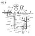
- Fig. 2illustrates an erosion device for performing a method.
- the electrode 2 of the erosion deviceconsists for example of tungsten-copper, preferably of graphite, and is attached to the wall of the present for reasons of radiation protection under water W plant part 4.
- the part of the plant 4 shown in detail in the figureis, for example, the cylindrical core jacket (core enclosure) of a reactor pressure vessel of a nuclear facility intended for demolition.
- a voltageis applied with a current or voltage source U and generates an arc that causes the system part 4 melted in one of the electrode 2 opposite surface area and this Way is removed.
- the used Abtrags videcorresponds technologically largely to the cutting from the ATW 51, 2006, Issue 3, pp. 170 to 172 known so-called “Contact Arc Metal Cutting (CAMC)" - method in which a submerged W, electrically conductive metallic material is slowly melted in a cyclic process of resistance heating and free-burning high current arc.
- the resulting gases Gmainly hydrogen and oxygen, are sucked off with a suction hood 8 arranged above the water surface 6.
- the electrode 2is guided by a hood 10, which is placed on the plant part 2 and serves to catch the one hand, the resulting coarse grout material during melting and on the other hand to prevent contamination of the system part 4 surrounding water with suspended matter.
- the located within the hood 10 and contaminated by the erosion process with suspended water Wis permanently sucked and cleaned by means of a suction and filter device 12.
- the hood 10is placed either on the plant part 4, leaving one or more gaps, or provided with a series of openings, so that the water W located inside the hood 10 is permanently replaced and replaced by fresh water W from the environment.
- the electrode 2has the shape of a flat, extending in a longitudinal direction web or cuboid with a narrow rectangular end face.
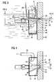
- Fig. 2 and 3the device is shown in a working position in which the electrode 2 has already penetrated into the wall of the plant part 4 and there has formed a pocket 30.
- the melting of the plant part 4takes place in the first place in one of the end face 22 of the electrode 2 opposite zone of the wall of the plant part 4.
- the electrode 2 surrounding gap space 34in which the melted grout material collects.
- a purge line 36is led into the interior 10 of the hood 10 through which the electrode 2 at its free end surrounding hood 10, from which a purge jet S exits.
- the purge jet Sis on directed the gap space 34 formed between an upper flat side of the electrode 2 and the wall of the pocket 30.
- the center axis 38 of the flushing jet S emerging from the free end of the flushing line 36is oriented at an angle ⁇ at an angle to the flat side of the electrode 2.
- the projection of the center axis 38 on the flat side of the electrodealso runs at an oblique angle ⁇ to the feed direction 32.
- the hood 10is disposed leaving a gap 44 between the edge of the hood 10 and the wall of the plant part 4 on the system part 4, so that in the interior of the hood 10 permanently fresh water W can flow from the environment and the suction of water W a permanent water flow within the hood 10 is generated.
- the hood 10is provided in its lower working position with a collecting trough 46 in which with the help of the purge jet S expelled from the molten zone coarse melt 48 can be collected. During the sinking of the melt 48 this cools on its surface, so that it is already solidified when encountered in the drip pan 46 at least in its outer area and not with the hood 10 can weld.
- the hood 10is open in its upper position in the working position.
- the electrode 2is now advanced until it penetrates the wall of the plant part 4 and in this way one in the 3 and 4 Dashed lines indicated narrow, the shape of the electrode 2 corresponding passage opening 50 generates, the width of which is greater than its height.
- FIGS. 5 and 6is the outlet opening of the purge line 36 as a flat and conically widening in a plane nozzle 52 designed, from which the purge jet S emerges fan-shaped so that it completely covers the gap space 34 located between the flat side of the electrode 2 and the plant part 4 within the pocket 30 , A portion of the purge jet W is passed past the gap space 34 so that it supports the formation of swirl.
- a Kernum chargedin this a plurality of cross-section approximately rectangular through holes 50 are introduced, which are mutually spaced in horizontal planes 60.
- band sawis then starting from an end face 62 of the plant part 4, a first saw cut 64, in the example, a vertical section, performed, which opens into the passage opening 50 at its lateral edge.
- a second, substantially parallel thereto extending saw cut 66is performed, which also extends to the through hole 50, so that between the saw cuts 64 and 66 located portion 68 is cut out.
- This portion 68is removed so that a saw band running in the band saw can be turned in the area of the recess formed in this way. Subsequently, with the turned band saw blade, for example, transverse to the first and second saw cuts 64 and 66 extending further saw cut 70, in the example, a horizontal section performed, so that in the example, the plant part 4 is gradually decomposed into a plurality of shots.
Landscapes
- Physics & Mathematics (AREA)
- Engineering & Computer Science (AREA)
- General Engineering & Computer Science (AREA)
- High Energy & Nuclear Physics (AREA)
- Plasma & Fusion (AREA)
- Electrical Discharge Machining, Electrochemical Machining, And Combined Machining (AREA)
- Arc Welding In General (AREA)
- Working Measures On Existing Buildindgs (AREA)
Description
Translated fromGermanDie Erfindung bezieht sich auf ein Verfahren zum Zerlegen eines unter Wasser befindlichen Anlagenteils einer kerntechnischen Anlage. Außerdem bezieht sich die Erfindung auf eine Vorrichtung zum Durchführen des Verfahrens.The invention relates to a method for disassembling an underwater system part of a nuclear installation. In addition, the invention relates to an apparatus for carrying out the method.
Beim Rückbau einer stillgelegten kerntechnischen Anlage, beispielsweise eines Kernkraftwerkes, gibt es eine Vielzahl radioaktiv kontaminierter Anlagenteile, die vor ihrer Entsorgung in transportierbare Bestandteile zerlegt werden müssen. Um eine radioaktive Belastung des die Zerlegung durchführenden Bedienpersonals zu verhindern, muss eine solche Zerlegung fernbedient unter Wasser durchgeführt werden. Darüber hinaus sollte das Zerlegen mit Geräten und Verfahren stattfinden, bei denen möglichst wenig Sekundärabfall, beispielsweise Späne oder Staub, entsteht, der neben einer Verunreinigung des Wassers auch zu einer die korrekte Durchführung der Zerlegung behindernden Sichteinschränkung führen kann. Bei solchen Anlagenteilen handelt es sich außerdem oftmals um strukturell komplizierte Gebilde mit schwer zugänglichen Bestandteilen, die einen Einsatz spezieller Zerlegevorrichtungen erfordern.When decommissioning a decommissioned nuclear facility, such as a nuclear power plant, there are a variety radioactively contaminated parts of the system, which must be broken down into transportable components before their disposal. In order to prevent radioactive contamination of the operator performing the cutting, such cutting must be carried out remotely under water. In addition, the disassembly should take place with equipment and procedures in which the least possible secondary waste, such as shavings or dust, is produced, which in addition to contamination of the water can also lead to a correct implementation of disassembly obstructing visual impairment. In addition, such parts are often structurally complex structures with hard-to-reach components that require the use of special cutting devices.
Dabei werden für die Zerlegung bevorzugt mechanische Zerlegwerkzeuge - Säge-, Fräs- oder Bohrwerkzeuge - verwendet, da der mit solchen Werkzeugen entstehende Sekundärabfall hauptsächlich aus groben Partikeln besteht, dessen Handhabung und Entsorgung vereinfacht ist, da er nicht zu einer weitreichenden Trübung und Verunreinigung des im Bereich des Anlagenteils befindlichen Wassers führt. Aus diesem Grund wird die Zerlegung großer hohlzylindrischer Komponenten eines stillgelegten Kernkraftwerkes, beispielsweise einer Kernumfassung, mit einer Bandsäge durchgeführt. Hierzu werden in der Kernumfassung sogenannte Wendelöcher benötigt, in denen ein vertikal (in Richtung der vertikalen Achse des zylindrischen Anlagenteils) ankommendes Sägeband um 90° in die Horizontale gedreht werden kann, um mit einem Horizontalschnitt beginnen zu können, mit dem ein ringförmiger Abschnitt - ein sogenannter Schuss - abgetrennt wird. Danach wird erneut vertikal bis zum nächsten Wendeloch geschnitten, das Sägeblatt gewendet und erneut horizontal gesägt um auf diese Weise den darunter liegenden Schuss abtrennen zu können. Auf diese Weise werden z.B. im Kernmantel sechs Wendelöcher für sieben Schüsse eingebracht.Here are preferably used for the decomposition mechanical cutting tools - sawing, milling or drilling tools - used as the secondary waste resulting from such tools mainly consists of coarse particles, its handling and Disposal is simplified because it does not lead to a far-reaching turbidity and contamination of the water located in the part of the system part. For this reason, the dismantling of large hollow cylindrical components of a decommissioned nuclear power plant, such as a Kernumfassung, performed with a band saw. For this purpose, so-called spiral holes are required in the Kernumfassung in which a vertically (in the direction of the vertical axis of the cylindrical part of the system) incoming saw blade can be rotated by 90 ° in the horizontal to start with a horizontal section, with an annular section - a so-called shot - is separated. Thereafter, it is again cut vertically until the next coiling hole, the saw blade turned and sawed again horizontally in order to be able to separate the underlying shot in this way. In this way, for example, six spiral holes for seven shots are introduced in the core sheath.
Diese Wendelöcher müssen ausreichend groß sein, um das Drehen des Sägeblattes der Bandsäge zu ermöglichen. Bei Verwendung eines hartmetallbestückten Fräs- oder Bohrwerkzeuges muss deshalb ein Wendeloch mit einem Durchmesser von wenigstens 50mm eingebracht werden. Um dies in einen Stahlmantel mit einer Wandstärke von etwa 80mm bewerkstelligen zu können, muss das Werkzeug sehr massiv ausgeführt sein und schwingungsfrei an der zu zerlegenden Komponente positioniert werden. Die Anlagenteile eines zum Rückbau vorgesehenen Kernkraftwerkes sind jedoch in Folge langjähriger radioaktiver Bestrahlung aktiviert und dadurch erheblich versprödet. Aufgrund der hohen Aktivität dieser Anlagenteile können Vorversuche allenfalls an nichtaktivierten Anlagenteilen durchgeführt werden. Deshalb besteht ein erhebliches Risiko, dass das verwendete Zerlegewerkzeug beim praktischen Einsatz selbst dann zerstört wird, wenn die an nicht aktivierten Werkstücken vorgenommenen Vorversuche positiv verlaufen sind. Die bisherige Vorgehensweise, bei denen aufwendige Fräs- bzw. Bohrwerkzeuge eingesetzt worden sind, haben deshalb in der praktischen Anwendung den Nachteil, dass im Falle eines Blockierens und anschließenden Bruchs, bei dem das Werkzeug in der Wand stecken bleibt, ein zusätzliches Interventionswerkzeug eingesetzt werden muss. Mit diesem muss entweder der abgebrochen Fräskopf oder Bohrer ausgebohrt werden oder es muss ein neues Wendeloch außerhalb der geplanten horizontalen Ebene eingefügt werden, da mit der Bandsäge die mit einem Hartmetall bestückten Werkzeuge nicht durchschnitten werden können. Dies erfordert einen erhöhten Bearbeitungsaufwand. Durch die Verlagerung des Horizontalschnittes in eine andere Ebene haben die zerlegten Teile außerdem eine Abmessung, die von der geplanten und hinsichtlich der weiteren Behandlung optimierten Abmessung abweicht. So werden beispielsweise entweder die für die zerlegten Teile vorgesehenen Transport- oder Endlagerbehälter ungenügend ausgenutzt oder es müssen zusätzliche Transport- oder Endlagerbehälter zur Verfügung gestellt werden.These coil holes must be large enough to allow the band saw blade to be turned. When using a carbide-tipped milling or drilling tool therefore a spiral hole must be introduced with a diameter of at least 50mm. To accomplish this in a steel jacket with a wall thickness of about 80mm, the tool must be made very solid and positioned vibration-free on the component to be disaggregated. However, the plant components of a decommissioning nuclear power plant are activated as a result of many years of radioactive irradiation and thus significantly embrittled. Due to the high activity of these parts of the plant, preliminary tests can be carried out on non-activated parts of the plant. Therefore, there is a considerable risk that the cutting tool used destroyed even in practical use if the preliminary tests made on non-activated workpieces are positive. The previous approach, in which complex milling or drilling tools have been used, therefore have the disadvantage in practice that in the case of blocking and subsequent breakage, in which the tool gets stuck in the wall, an additional intervention tool must be used , With this, either the aborted milling head or drill must be drilled out or a new helical hole must be inserted outside the planned horizontal plane, since the band saw can not cut through the tools equipped with a carbide metal. This requires an increased processing costs. Due to the displacement of the horizontal section in another plane, the disassembled parts also have a dimension that deviates from the planned and optimized for further treatment dimension. Thus, for example, either provided for the disassembled parts transport or repository containers are insufficiently utilized or additional transport or disposal containers must be provided.
Der Erfindung liegt nun die Aufgabe zu Grunde, ein Verfahren zum Zerlegen eines unter Wasser befindlichen Anlagenteils einer kerntechnischen Anlage anzugeben, mit dem die vorstehend genannte Nachteile vermieden sind. Außerdem liegt der Erfindung die Aufgabe zu Grunde, eine nach diesem Verfahren arbeitende Vorrichtung anzugeben.The invention is based on the object to provide a method for disassembling an underwater system part of a nuclear installation, with which the above-mentioned disadvantages are avoided. In addition, the invention is based on the object to provide a device operating according to this method.
Hinsichtlich des Verfahrens wird die Aufgabe gemäß der Erfindung gelöst mit einem Verfahren mit den Merkmalen des Patentanspruches 1. Gemäß diesen Merkmalen wird bei einem Verfahren zum Zerlegen eines unter Wasser befindlichen Anlagenteils In eine Wand des Anlagenteils mit einem elektrischen Erodierverfahren zumindest eine im Querschnitt annähernd rechteckförmige Durchgangsöffnung eingebracht. Anschließend wird mit einer Säge ausgehend von einer Stirnseite des Anlagenteiles zumindest ein erster Sägeschnitt eingebracht, der in die Durchgangsöffnung mündet. Ein Sägeblatt der Säge wird im Bereich der Durchgangsöffnung gewendet und es wird in einer von der Richtung des ersten Sägeschnittes abweichenden Richtung ein weiterer Sägeschnitt durchgeführt.With regard to the method, the object is achieved according to the invention with a method having the features of claim 1. According to these features, in a method for disassembling an underwater system part In a wall of the plant part with an electric erosion process at least one cross-sectionally approximately rectangular passage opening introduced. Subsequently, with a saw, starting from an end face of the plant part, at least one first saw cut is introduced, which opens into the passage opening. A saw blade of the saw is turned in the region of the passage opening and a further saw cut is carried out in a direction deviating from the direction of the first saw cut.
Die Erfindung beruht dabei auf der Idee, dass ein beispielsweise aus der der
Wenn in einer alternativen Variante des Verfahrens neben dem ersten Sägeschnitt ein zweiter Sägeschnitt eingebracht wird, der in dieselbe Durchgangsöffnung mündet, und ein auf diese Weise zwischen den Sägeschnitten ausgetrennte Teilstück der Wand entfernt und das Sägeblatt in der auf diese Weise entstehenden Ausnehmung gewendet wird, ist es ausreichend, mit dem Erodierverfahren lediglich eine schmale und noch nicht als Wendeloch geeignete Durchgangsöffnung einzubringen, da die für das Wenden des Sägeblattes erforderliche Höhe der Durchgangsöffnung durch das Einbringen der Ausnehmung erzeugt wird. Dadurch wird zusätzlich die Menge des beim Erodieren entstehenden Sekundärabfalles verringert.If, in an alternative variant of the method, a second saw cut is introduced in addition to the first saw cut, which opens into the same through-opening, and one on this Way removed between the saw cuts severed portion of the wall and the saw blade is turned in the resulting recess in this way, it is sufficient to introduce the Erodierverfahren only a narrow and not yet suitable as a turn hole through hole, as required for the turning of the saw blade height the passage opening is generated by the introduction of the recess. This also reduces the amount of secondary waste generated during erosion.
Bei einer bevorzugten Ausgestaltung des Erodierverfahrens wird zwischen einer Elektrode und einer Wand des Anlagenteils durch Anlegen einer elektrischen Spannung ein Lichtbogen erzeugt. Die Elektrode wird anschließend in einer Vorschubrichtung mit ihrer Stirnseite gegen die Wand vorgeschoben, so dass sie durch Aufschmelzen des Anlagenteils im Bereich des Lichtbogens in dieses eindringt und in der Wand eine die Elektrode umgebende Tasche erzeugt. Die beim Aufschmelzen des Anlagenteils in der Tasche entstehende Schmelze wird durch einen Spülstrahl aus der Tasche ausgetrieben und die Vorschubbewegung wird solange fortgeführt bis die Elektrode die Wand durchdringt und auf diese Weise die Durchgangsöffnung in der Wand erzeugt.In a preferred embodiment of the erosion process, an arc is generated between an electrode and a wall of the plant part by applying an electrical voltage. The electrode is then advanced in a feed direction with its end face against the wall, so that it penetrates by melting the plant part in the arc in this and generates a pocket surrounding the electrode in the wall. The resulting in the melting of the plant part melt in the bag is expelled from the bag by a purging and the feed movement is continued until the electrode penetrates the wall and in this way creates the passage opening in the wall.
Wenn die Elektrode die Form eines Steges mit zwei einander gegenüberliegenden Flachseiten aufweist, und der Spülstrahl derart auf einen zwischen einer Flachseite der Elektrode und der Wand der Tasche gebildeten Spalt gerichtet ist, dass die auf die Flachseite der Elektrode projizierte Mittenachse des Spülstrahls unter einem schiefen Winkel zur Vorschubrichtung verläuft, wird ein effizientes Austreiben der Schmelze aus dem zwischen dem Werkstück und der Elektrode befindlichen Spaltraum bewirkt und ein als "side arcing" bezeichneter erhöhter seitlicher Elektrodenverschleiß vermieden.When the electrode is in the form of a ridge with two opposite flat sides, and the rinsing beam is directed onto a gap formed between a flat side of the electrode and the wall of the pocket, the central axis of the rinsing jet projected onto the flat side of the electrode is at an oblique angle extends to the feed direction, an efficient expulsion of the melt from the space located between the workpiece and the electrode gap causes and called a "side arcing" increased lateral electrode wear avoided.
Diese Vorgehensweise beruht dabei auf der Überlegung, dass durch einen auf den zwischen Elektrode und Tasche gebildeten Spaltraum unter einem schiefen Winkel zur Vorschubrichtung orientierter Spülstrahl auch bei relativ geringer Intensität eine erheblich effektivere und gleichmäßigere Spülleistung ermöglicht. Durch den schräg in diesen Spaltraum gerichteten Spülstrahl wird nämlich ein Drall erzeugt, der das Austreiben des Schmelzgutes verbessert. Da der Spülstrahl nur mehr eine relativ geringe Intensität aufweisen muss, sind zu dessen Erzeugung nur noch relativ leistungsschwache Pumpen erforderlich.This procedure is based on the consideration that by a gap formed on the gap formed between the electrode and pocket at an oblique angle to the feed direction, even at relatively low intensity allows a much more effective and uniform flushing performance. By the directed obliquely into this gap space purge jet, namely a swirl is generated, which improves the expulsion of the melt. Since the purge jet only has to have a relatively low intensity, only relatively low-performance pumps are required to produce it.
Wenn der Spülstrahl zusätzlich schräg zur Flachseite der Elektrode gerichtet ist, ist das Ausmaß der Drall- bzw. Wirbelbildung und damit die Spülleistung zusätzlich erhöht. Darüber hinaus hat es sich als besonders vorteilhaft herausgestellt, wenn der Spülstrahl an nur einer Flachseite der Elektrode in den Spalt trifft, nämlich bei horizontaler Ausrichtung der Elektrode in Arbeitsstellung der obenliegenden Flachseite.If the purging jet is additionally directed obliquely to the flat side of the electrode, the extent of the swirl or vortex formation and thus the flushing power is additionally increased. In addition, it has been found to be particularly advantageous if the purge jet strikes the gap in only one flat side of the electrode, namely in the horizontal position of the electrode in the working position of the upper flat side.
In einer bevorzugten Ausgestaltung hat der Spülstrahl die Form eines annähernd parallel zum Spaltraum orientierten Fächers, um auf diese Weise den parallel zur Flachseite der Elektrode verlaufenden Spaltraum vollständig zu erfassen und die Spülleistung zu erhöhen.In a preferred embodiment, the purging jet has the shape of a fan oriented approximately parallel to the gap in order in this way to completely grasp the gap space running parallel to the flat side of the electrode and to increase the purging performance.
Weitere vorteilhafte Ausgestaltungen des Verfahrens sind in den Patentansprüchen 8 bis 12 angegeben.Further advantageous embodiments of the method are specified in the
Hinsichtlich der Vorrichtung wird die genannte Aufgabe gemäß der Erfindung gelöst mit einer Vorrichtung mit den Merkmalen des Patentanspruches 13, deren Vorteile sinngemäß den zu den Patentanspruch 1 angegebenen Vorteilen entsprechen. Vorteilhafte Ausgestaltungen der Vorrichtung sind in den auf Patentanspruch 13 zurück bezogenen Unteransprüchen angegeben.With regard to the device, said object is achieved according to the invention with a device having the features of claim 13, the advantages of which correspond mutatis mutandis to the advantages indicated in claim 1. Advantageous embodiments of the device are specified in the recited in claim 13 dependent claims.
Zur weiteren Erläuterung der Erfindung wird auf das Ausführungsbeispiel der Zeichnung verwiesen. Es zeigen:
- Fig. 1
- eine Vorrichtung zur Durchführung des Verfahrens gemäß der Erfindung in einem schematischen Prinzipbild,
- Fig. 2
- eine an eine Wand des Anlagenteils angestellte, bei dem erfindungsgemäßen Verfahren vorzugsweise verwendete Erodiervorrichtung ebenfalls in einem Prinzipbild,
- Fig. 3
- und 4 die Erodiervorrichtung in einer Arbeitsposition in einem Längs- bzw. Querschnitt jeweils in einer sche- matischen Prinzipdarstellung,
- Fig. 5
- und 6 jeweils eine Düse in einer Seitenansicht bzw. Draufsicht, aus der der Spülstrahl austritt.
- Fig. 7
- eine schematische Darstellung, anhand der eine vorteil- hafte Ausgestaltung des Verfahrens gemäß der Erfindung veranschaulicht wird.
- Fig. 1
- an apparatus for carrying out the method according to the invention in a schematic schematic diagram,
- Fig. 2
- an erosion device which is employed on a wall of the plant part and which is preferably used in the method according to the invention, likewise in a schematic diagram,
- Fig. 3
- and FIG. 4 shows the erosion device in a working position in a longitudinal or cross section, each in a schematic representation of the principle,
- Fig. 5
- and FIG. 6 each show a nozzle in a side view and a top view, respectively, from which the flushing jet emerges.
- Fig. 7
- a schematic representation, based on an advantageous embodiment of the method according to the invention is illustrated.
Gemäß
Zwischen dem aus einem elektrischen leitfähigen Werkstoff bestehenden Anlagenteil 4 und der Elektrode 2 wird mit einer Strom- bzw. Spannungsquelle U eine Spannung angelegt und ein Lichtbogen erzeugt, der dazu führt, dass das Anlagenteil 4 in einem der Elektrode 2 gegenüberliegenden Oberflächenbereich aufgeschmolzen und auf diese Weise abgetragen wird. Das verwendete Abtragsverfahren entspricht technologisch weitgehend dem zum Schneiden aus der
Die Elektrode 2 ist durch eine Haube 10 geführt, die auf das Anlagenteil 2 aufgesetzt ist und dazu dient, einerseits das beim Aufschmelzen entstehende grobe Fugenmaterial aufzufangen und andererseits eine Verschmutzung des das Anlagenteil 4 umgebenden Wassers mit Schwebstoffen zu verhindern. Das innerhalb der Haube 10 befindliche und durch den Erodiervorgang mit Schwebstoffen verunreinigte Wasser W wird mit Hilfe einer Absaug- und Filtereinrichtung 12 permanent abgesaugt und gereinigt. Die Haube 10 ist hierzu entweder unter Belassung eines oder mehrerer Spalte auf das Anlagenteil 4 aufgesetzt oder mit einer Reihe von Öffnungen versehen, so dass das innerhalb der Haube 10 befindliche Wasser W permanent ausgetauscht und durch frisches Wasser W aus der Umgebung ersetzt wird.The
Die Zustellung der Elektrode 2 an das Anlagenteil 4 erfolgt über einen in der Figur nur schematisch angedeuteten, mit Wasser gefüllten kolbenstangenlosen pneumatischen Linearzylinder 14, der über Pneumatikleitungen 16 mit einem baugleichen Linearzylinder 18 verbunden ist, der sich bedienerseitig auf einer Arbeitsplattform 20 befindet. Auf diese Weise kann die Elektrode 2 durch manuelles Betätigen des Linearzylinders 18 mit einer 1:1-Übersetzung mit ihrer Stirnseite in eine Vorschubrichtung - in der Figur angedeutet durch Doppelpfeile - vorgeschoben werden. Ein solcher vom Bediener vorgenommener manueller Vorschub bietet diesem eine unmittelbare Rückkopplung der auf die Elektrode 2 wirkenden Kraft und erleichtert ihm, die Vorschubbewegung der Elektrode 2 korrekt einzustellen. Der Einsatz parallel geschalteter, wassergefüllter pneumatischer Linearzylinder 14, 16 hat dabei den Vorteil, dass diese auch mit Wasserfüllung sehr reibungsarm laufen und keine Hydraulikpumpe für den Aufbau eines Systems benötigen. Für den Fall, dass höhere Zustellkräfte erforderlich sind, ist es auch möglich, zum Bedienen einen Linearzylinder 18 zu verwenden, der einen geringeren Innendurchmesser als der Linearzylinder 14 und damit einen größeren Hub als dieser aufweist. Alternativ hierzu sind auch grundsätzlich andere Antriebsarten, beispielsweise pneumatische Schwenkantriebe oder Spindelantriebe einsetzbar. Ebenso kann anstelle eines manuellen Vorschubs auch ein automatischer Vorschub vorgesehen sein.The delivery of the
Den
Zum Austreiben des Fugenmaterials aus dem zwischen der Elektrode 2 und dem Anlagenteil 4 gebildeten Spaltraum 34 ist durch die die Elektrode 2 an ihrem freien Ende umgebenden Haube 10 eine Spülleitung 36 in den Innenraum 10 der Haube 10 geführt, aus der ein Spülstrahl S austritt. Der Spülstrahl S ist auf den zwischen einer oberen Flachseite der Elektrode 2 und der Wand der Tasche 30 gebildeten Spaltraum 34 gerichtet. Die Mittenachse 38 des aus dem freien Ende der Spülleitung 36 austretenden Spülstrahls S ist dabei unter einem Winkel α schräg zur Flachseite der Elektrode 2 orientiert. Die Projektion der Mittenachse 38 auf die Flachseite der Elektrode verläuft ebenfalls unter einem schiefen Winkel β zur Vorschubrichtung 32. Auf diese Weise wird innerhalb der Haube 10 ein Drall und damit eine Zyklonwirkung erzeugt, die das Austreiben und Aufsammeln des Fugenmaterials signifikant verbessert. Unterstützt wird diese Zyklonwirkung außerdem durch die permanente Absaugung von Wasser W aus dem Innenraum der Haube 10 über ein in das Innere der Haube 10 führendes und im Inneren der Haube 10 gekrümmtes Saugrohr 40, dessen Saugöffnung 42 von der Wand des Anlagenteils 4 abgewandt ist und sich in einem Randbereich des Innenraums der Haube 10 befindet.To expel the joint material from the
Die Haube 10 ist unter Belassung eines Spaltes 44 zwischen dem Rand der Haube 10 und der Wand des Anlagenteils 4 am Anlagenteil 4 angeordnet, so dass in den Innenraum der Haube 10 permanent frisches Wasser W aus der Umgebung nachströmen kann und beim Absaugen von Wasser W ein permanenter Wasserstrom innerhalb der Haube 10 erzeugt wird.The
Die Haube 10 ist in ihrem in Arbeitsposition unterem Bereich mit einer Auffangwanne 46 versehen in der das mit Hilfe des Spülstrahls S aus der Schmelzzone ausgetriebene grobe Schmelzgut 48 aufgefangen werden kann. Während des Absinkens des Schmelzgutes 48 erkaltet dieses an seiner Oberfläche, so dass es beim Antreffen in der Auffangwanne 46 zumindest in seinem Außenbereich bereits erstarrt ist und nicht mehr mit der Haube 10 verschweißen kann. Im Ausführungsbeispiel ist die Haube 10 in ihrem in Arbeitsposition oberen Bereich offen.The
Die Elektrode 2 wird nun so lange vorgeschoben, bis sie die Wand des Anlagenteils 4 durchdringt und auf diese Weise eine in den
Gemäß
Bei der in
Claims (16)
- Method for dismantling a submerged assembly component (4) of a nuclear facility, comprising the following steps:a) at least one opening (50), which is nearly rectangular in its cross-section, is introduced into a wall of the assembly component (4) with an electrical erosion process,b) at least one first saw cut (64) is introduced with a saw from a front side of the assembly component, which opens out into the opening,c) a saw blade (80) of the saw (82) is turned in the opening (50) and a further saw cut (70) is carried out in a direction differing from the direction of the first saw cut (64).
- Method for dismantling a submerged assembly component (4) of a nuclear facility, comprising the following steps:a) at least one opening (50), which is nearly rectangular in its cross-section, is introduced into a wall of the assembly component (4) with an electrical erosion process,b) at least one first saw cut (64) is introduced with a saw from a front side of the assembly component, which opens out into the opening,c) as well as the first saw cut (64), a second saw cut (66) is introduced, which opens out into the same opening (50),d) a section (68) of the wall separated between the saw cuts in this way is removed and the saw blade (80) is turned in the cavity that arises in this way.
- Method according to claim 1 or 2, wherein a band saw is used as the saw (82), the saw band of which is used in the opening (50) or cavity.
- Method according to one of the preceding claims, having the following further features:a) an electric arc is generated between an electrode (2) and the wall of the assembly component (4) by applying an electrical voltage (U),b) the electrode (2) is moved with its front side against the wall in a feed direction (32), such that, by melting the assembly component (4) in the region of the electric arc, it penetrates this, and a recess (30) surrounding the electrode (2) is produced in the wall,c) a molten material arising during the melting of the assembly component (4) in the recess (30) is discharged from the recess (30) by a water jet (S),d) the feed movement is continued until the electrode (2) penetrates the wall and the opening (50) in the wall is produced in this way.
- Method according to claim 4, wherein the electrode has the shape of a bar with two flat sides opposite each another, and wherein the water jet is aligned onto a gap formed between a flat side of the electrode and the wall of the recess in such a way that the central axis of the water jet projected onto the flat side of the electrode runs at an oblique angle with respect to the feed direction.
- Method according to claim 5, wherein the water jet is aligned at an angle to the flat side of the electrode.
- Method according to claim 5 or 6, wherein the water jet has the shape of a fan.
- Method according to claim 5, 6, or 7, wherein the electrode is aligned with its flat side almost perpendicular to the vertical, and wherein the water jet is directed into the gap located above the electrode.
- Method according to one of claims 5 to 8, wherein the molten material discharged by the water jet is collected in a collecting container.
- Method according to claim 9, wherein a hood is used as a collecting container, in which the free end of the electrode is arranged, and which is engaged with the wall with its edge surrounding an opening in the hood.
- Method according to claim 10, wherein water is sucked out of the hood and filtered and water flows from the space surrounding the hood into the interior of the hood.
- Method according to one of the preceding claims, wherein the gases arising above the surface of the water during erosion by melting the assembly components are collected in a suction hood.
- Method for carrying out the method according to claim 1 or 2, having:a) an erosion device with an electrode (2) that is nearly rectangular in its cross-section and that can be engaged with a wall of the assembly component (4), andb) a saw (82) that can be engaged with a front face of the assembly component for introducing a saw cut (64) into the opening (50), with a turnable saw blade (82).
- Device according to claim 13, wherein the saw is a band saw.
- Device according to claim 13 or 14, having:a) an electrode having the shape of a bar with two opposite flat sides, which is mounted displaceably in a feed direction running parallel to the flat side,b) a voltage source for generating a voltage and an electric arc caused thereby between the electrode and the assembly component,c) a nozzle arranged above a flat side of the electrode for generating a water jet pointing towards the front face of the electrode for discharging a molten material arising during the melting of the assembly component, which is aligned onto a gap formed between a flat side of the electrode and the wall of the recess in such a way that the central axis of the water jet projected onto the flat side of the electrode runs at an oblique angle with respect to the feed direction.
- Device according to claim 15, having a collecting container for collecting the molten material discharged by the water jet, said container being designed as a hood in which the free end of the electrode is arranged and which can be engaged with the wall with its edge surrounding an opening in the hood.
Applications Claiming Priority (1)
| Application Number | Priority Date | Filing Date | Title |
|---|---|---|---|
| DE102009001238ADE102009001238A1 (en) | 2009-02-27 | 2009-02-27 | A method of separating a submerged part of a nuclear facility and apparatus for carrying out the method |
Publications (3)
| Publication Number | Publication Date |
|---|---|
| EP2224455A2 EP2224455A2 (en) | 2010-09-01 |
| EP2224455A3 EP2224455A3 (en) | 2013-01-02 |
| EP2224455B1true EP2224455B1 (en) | 2013-07-24 |
Family
ID=42262617
Family Applications (1)
| Application Number | Title | Priority Date | Filing Date |
|---|---|---|---|
| EP10153182.0ANot-in-forceEP2224455B1 (en) | 2009-02-27 | 2010-02-10 | Method for dismantling an assembly component of a nuclear facility under water and device for carrying out the method |
Country Status (3)
| Country | Link |
|---|---|
| EP (1) | EP2224455B1 (en) |
| DE (1) | DE102009001238A1 (en) |
| ES (1) | ES2430070T3 (en) |
Cited By (1)
| Publication number | Priority date | Publication date | Assignee | Title |
|---|---|---|---|---|
| RU2752410C2 (en)* | 2015-02-10 | 2021-07-27 | Российская Федерация | Section of modules of vertical steam generator |
Families Citing this family (1)
| Publication number | Priority date | Publication date | Assignee | Title |
|---|---|---|---|---|
| DE102011004659B3 (en)* | 2011-02-24 | 2012-02-09 | Areva Np Gmbh | Process for dismantling an activated hollow cylindrical container of a nuclear installation |
Family Cites Families (5)
| Publication number | Priority date | Publication date | Assignee | Title |
|---|---|---|---|---|
| DE3764402D1 (en)* | 1986-06-02 | 1990-09-27 | Siemens Ag | METHOD AND ARRANGEMENT FOR WET DISASSEMBLY OF RADIOACTIVELY CONTAMINATED OR ACTIVATED COMPONENTS OF NUCLEAR REACTORS. |
| FR2682803B1 (en)* | 1991-10-21 | 1993-12-03 | Framatome | PROCESS AND DEVICE FOR TAKING A TEST PIECE IN THE TANK OF A NUCLEAR REACTOR IN DEFINITIVE STOP. |
| DE4332882A1 (en)* | 1993-09-21 | 1995-03-23 | Neschan Prof Dr Neschanjan | Device for radiation protection shielding of the water surface during the cutting of irradiated reactor parts under water |
| DE19642519A1 (en)* | 1996-10-15 | 1998-04-16 | Gen Electric | Core shroud support plate machining |
| DE102005050942A1 (en)* | 2005-10-21 | 2007-05-03 | Areva Np Gmbh | Method and device for disassembling a built-in part of a nuclear reactor pressure vessel |
- 2009
- 2009-02-27DEDE102009001238Apatent/DE102009001238A1/ennot_activeWithdrawn
- 2010
- 2010-02-10ESES10153182Tpatent/ES2430070T3/enactiveActive
- 2010-02-10EPEP10153182.0Apatent/EP2224455B1/ennot_activeNot-in-force
Cited By (1)
| Publication number | Priority date | Publication date | Assignee | Title |
|---|---|---|---|---|
| RU2752410C2 (en)* | 2015-02-10 | 2021-07-27 | Российская Федерация | Section of modules of vertical steam generator |
Also Published As
| Publication number | Publication date |
|---|---|
| EP2224455A2 (en) | 2010-09-01 |
| EP2224455A3 (en) | 2013-01-02 |
| ES2430070T3 (en) | 2013-11-18 |
| DE102009001238A1 (en) | 2010-11-11 |
Similar Documents
| Publication | Publication Date | Title |
|---|---|---|
| DE69515148T2 (en) | A laser treatment head for a laser treatment device | |
| EP1920873B1 (en) | Method for laser beam cutting of a metal part | |
| EP1609556A1 (en) | Modular hybrid laser welding head | |
| EP3706140A1 (en) | Device and method for decontaminating a wall surface of in particular a hollow body | |
| EP2224455B1 (en) | Method for dismantling an assembly component of a nuclear facility under water and device for carrying out the method | |
| DE10226359A1 (en) | Laser processing head, especially for cutting workpiece using laser beam, has device near outlet opening between housing and laser nozzle for producing gas flow transverse to laser beam | |
| DE69204879T2 (en) | Method and device for working with laser in a contaminated zone of a nuclear plant. | |
| DE2857114C2 (en) | ||
| EP0671988B1 (en) | Method of manufacturing a filter plate for the foot of a nuclear-fuel element, and a fuel element fitted with such a filter plate | |
| DE2326558A1 (en) | METHOD AND DEVICE FOR REMOVING CORE FUEL ELEMENTS FROM FUEL CASES | |
| DE2512331A1 (en) | ELECTROEROSION PROCESS FOR THE PROCESSING OF WORK PIECES AND DEVICE FOR PERFORMING THIS PROCESS | |
| DE60307866T2 (en) | CUTTING CEMENT-CONTAINING MATERIALS | |
| EP0548707B1 (en) | Method and device to increase the water depth of a watercourse | |
| DE2420577C2 (en) | Method and apparatus for removing nuclear fuel from jacketed nuclear fuel assemblies | |
| DE19806278A1 (en) | Method for separating a radioactive component of a nuclear reactor and device therefor | |
| WO2021175557A1 (en) | Laser machine tool for machining workpieces | |
| EP2711117B1 (en) | Cutting device with a splash guard and method for cutting workpieces | |
| DE102019106382A1 (en) | Device and method for machining a wall surface of a particularly tubular hollow body | |
| DE3935645A1 (en) | Underwater disposal of spent nuclear fuel elements - by entering fuel elements into shaft for cutting and circulating water using filter as barrier against pollution entering pond | |
| DE3816912C2 (en) | ||
| DE3007876C2 (en) | Process for comminuting spent nuclear reactor fuel elements | |
| EP0473932B1 (en) | Device for the comminution of inner chips of longitudinally welded pipes | |
| DE8709361U1 (en) | Cutting tool for creating a hole in a steel-reinforced concrete wall | |
| DE19922169B4 (en) | Process for separating / cutting components, workpieces and / or test specimens of any thickness, size and other dimensions from concrete, stone and other mineral building materials with economically acceptable separation speeds | |
| EP4114609B1 (en) | Laser machine tool for machining workpieces |
Legal Events
| Date | Code | Title | Description |
|---|---|---|---|
| PUAI | Public reference made under article 153(3) epc to a published international application that has entered the european phase | Free format text:ORIGINAL CODE: 0009012 | |
| AK | Designated contracting states | Kind code of ref document:A2 Designated state(s):AT BE BG CH CY CZ DE DK EE ES FI FR GB GR HR HU IE IS IT LI LT LU LV MC MK MT NL NO PL PT RO SE SI SK SM TR | |
| AX | Request for extension of the european patent | Extension state:AL BA RS | |
| PUAL | Search report despatched | Free format text:ORIGINAL CODE: 0009013 | |
| AK | Designated contracting states | Kind code of ref document:A3 Designated state(s):AT BE BG CH CY CZ DE DK EE ES FI FR GB GR HR HU IE IS IT LI LT LU LV MC MK MT NL NO PL PT RO SE SI SK SM TR | |
| AX | Request for extension of the european patent | Extension state:AL BA RS | |
| RIC1 | Information provided on ipc code assigned before grant | Ipc:G21C 19/20 20060101ALI20121126BHEP Ipc:G21F 9/28 20060101ALI20121126BHEP Ipc:G21D 1/00 20060101AFI20121126BHEP | |
| 17P | Request for examination filed | Effective date:20130111 | |
| RAP1 | Party data changed (applicant data changed or rights of an application transferred) | Owner name:AREVA GMBH | |
| GRAP | Despatch of communication of intention to grant a patent | Free format text:ORIGINAL CODE: EPIDOSNIGR1 | |
| RIC1 | Information provided on ipc code assigned before grant | Ipc:G21F 9/28 20060101ALI20130218BHEP Ipc:G21C 19/20 20060101ALI20130218BHEP Ipc:G21D 1/00 20060101AFI20130218BHEP | |
| GRAS | Grant fee paid | Free format text:ORIGINAL CODE: EPIDOSNIGR3 | |
| GRAA | (expected) grant | Free format text:ORIGINAL CODE: 0009210 | |
| AK | Designated contracting states | Kind code of ref document:B1 Designated state(s):AT BE BG CH CY CZ DE DK EE ES FI FR GB GR HR HU IE IS IT LI LT LU LV MC MK MT NL NO PL PT RO SE SI SK SM TR | |
| REG | Reference to a national code | Ref country code:GB Ref legal event code:FG4D Free format text:NOT ENGLISH | |
| REG | Reference to a national code | Ref country code:CH Ref legal event code:EP | |
| REG | Reference to a national code | Ref country code:AT Ref legal event code:REF Ref document number:623845 Country of ref document:AT Kind code of ref document:T Effective date:20130815 | |
| REG | Reference to a national code | Ref country code:IE Ref legal event code:FG4D Free format text:LANGUAGE OF EP DOCUMENT: GERMAN | |
| REG | Reference to a national code | Ref country code:DE Ref legal event code:R096 Ref document number:502010004105 Country of ref document:DE Effective date:20130919 | |
| REG | Reference to a national code | Ref country code:SE Ref legal event code:TRGR | |
| REG | Reference to a national code | Ref country code:ES Ref legal event code:FG2A Ref document number:2430070 Country of ref document:ES Kind code of ref document:T3 Effective date:20131118 | |
| REG | Reference to a national code | Ref country code:NL Ref legal event code:VDEP Effective date:20130724 | |
| REG | Reference to a national code | Ref country code:LT Ref legal event code:MG4D | |
| PG25 | Lapsed in a contracting state [announced via postgrant information from national office to epo] | Ref country code:IS Free format text:LAPSE BECAUSE OF FAILURE TO SUBMIT A TRANSLATION OF THE DESCRIPTION OR TO PAY THE FEE WITHIN THE PRESCRIBED TIME-LIMIT Effective date:20131124 Ref country code:HR Free format text:LAPSE BECAUSE OF FAILURE TO SUBMIT A TRANSLATION OF THE DESCRIPTION OR TO PAY THE FEE WITHIN THE PRESCRIBED TIME-LIMIT Effective date:20130724 Ref country code:CY Free format text:LAPSE BECAUSE OF FAILURE TO SUBMIT A TRANSLATION OF THE DESCRIPTION OR TO PAY THE FEE WITHIN THE PRESCRIBED TIME-LIMIT Effective date:20130904 Ref country code:PT Free format text:LAPSE BECAUSE OF FAILURE TO SUBMIT A TRANSLATION OF THE DESCRIPTION OR TO PAY THE FEE WITHIN THE PRESCRIBED TIME-LIMIT Effective date:20131125 Ref country code:LT Free format text:LAPSE BECAUSE OF FAILURE TO SUBMIT A TRANSLATION OF THE DESCRIPTION OR TO PAY THE FEE WITHIN THE PRESCRIBED TIME-LIMIT Effective date:20130724 Ref country code:NO Free format text:LAPSE BECAUSE OF FAILURE TO SUBMIT A TRANSLATION OF THE DESCRIPTION OR TO PAY THE FEE WITHIN THE PRESCRIBED TIME-LIMIT Effective date:20131024 | |
| PG25 | Lapsed in a contracting state [announced via postgrant information from national office to epo] | Ref country code:LV Free format text:LAPSE BECAUSE OF FAILURE TO SUBMIT A TRANSLATION OF THE DESCRIPTION OR TO PAY THE FEE WITHIN THE PRESCRIBED TIME-LIMIT Effective date:20130724 Ref country code:GR Free format text:LAPSE BECAUSE OF FAILURE TO SUBMIT A TRANSLATION OF THE DESCRIPTION OR TO PAY THE FEE WITHIN THE PRESCRIBED TIME-LIMIT Effective date:20131025 Ref country code:SI Free format text:LAPSE BECAUSE OF FAILURE TO SUBMIT A TRANSLATION OF THE DESCRIPTION OR TO PAY THE FEE WITHIN THE PRESCRIBED TIME-LIMIT Effective date:20130724 Ref country code:PL Free format text:LAPSE BECAUSE OF FAILURE TO SUBMIT A TRANSLATION OF THE DESCRIPTION OR TO PAY THE FEE WITHIN THE PRESCRIBED TIME-LIMIT Effective date:20130724 Ref country code:NL Free format text:LAPSE BECAUSE OF FAILURE TO SUBMIT A TRANSLATION OF THE DESCRIPTION OR TO PAY THE FEE WITHIN THE PRESCRIBED TIME-LIMIT Effective date:20130724 Ref country code:FI Free format text:LAPSE BECAUSE OF FAILURE TO SUBMIT A TRANSLATION OF THE DESCRIPTION OR TO PAY THE FEE WITHIN THE PRESCRIBED TIME-LIMIT Effective date:20130724 | |
| PG25 | Lapsed in a contracting state [announced via postgrant information from national office to epo] | Ref country code:CY Free format text:LAPSE BECAUSE OF FAILURE TO SUBMIT A TRANSLATION OF THE DESCRIPTION OR TO PAY THE FEE WITHIN THE PRESCRIBED TIME-LIMIT Effective date:20130724 | |
| PG25 | Lapsed in a contracting state [announced via postgrant information from national office to epo] | Ref country code:CZ Free format text:LAPSE BECAUSE OF FAILURE TO SUBMIT A TRANSLATION OF THE DESCRIPTION OR TO PAY THE FEE WITHIN THE PRESCRIBED TIME-LIMIT Effective date:20130724 Ref country code:RO Free format text:LAPSE BECAUSE OF FAILURE TO SUBMIT A TRANSLATION OF THE DESCRIPTION OR TO PAY THE FEE WITHIN THE PRESCRIBED TIME-LIMIT Effective date:20130724 Ref country code:DK Free format text:LAPSE BECAUSE OF FAILURE TO SUBMIT A TRANSLATION OF THE DESCRIPTION OR TO PAY THE FEE WITHIN THE PRESCRIBED TIME-LIMIT Effective date:20130724 Ref country code:EE Free format text:LAPSE BECAUSE OF FAILURE TO SUBMIT A TRANSLATION OF THE DESCRIPTION OR TO PAY THE FEE WITHIN THE PRESCRIBED TIME-LIMIT Effective date:20130724 Ref country code:SK Free format text:LAPSE BECAUSE OF FAILURE TO SUBMIT A TRANSLATION OF THE DESCRIPTION OR TO PAY THE FEE WITHIN THE PRESCRIBED TIME-LIMIT Effective date:20130724 | |
| PG25 | Lapsed in a contracting state [announced via postgrant information from national office to epo] | Ref country code:IT Free format text:LAPSE BECAUSE OF FAILURE TO SUBMIT A TRANSLATION OF THE DESCRIPTION OR TO PAY THE FEE WITHIN THE PRESCRIBED TIME-LIMIT Effective date:20130724 | |
| PLBE | No opposition filed within time limit | Free format text:ORIGINAL CODE: 0009261 | |
| STAA | Information on the status of an ep patent application or granted ep patent | Free format text:STATUS: NO OPPOSITION FILED WITHIN TIME LIMIT | |
| 26N | No opposition filed | Effective date:20140425 | |
| REG | Reference to a national code | Ref country code:DE Ref legal event code:R097 Ref document number:502010004105 Country of ref document:DE Effective date:20140425 | |
| BERE | Be: lapsed | Owner name:AREVA G.M.B.H. Effective date:20140228 | |
| PG25 | Lapsed in a contracting state [announced via postgrant information from national office to epo] | Ref country code:MC Free format text:LAPSE BECAUSE OF FAILURE TO SUBMIT A TRANSLATION OF THE DESCRIPTION OR TO PAY THE FEE WITHIN THE PRESCRIBED TIME-LIMIT Effective date:20130724 Ref country code:LU Free format text:LAPSE BECAUSE OF FAILURE TO SUBMIT A TRANSLATION OF THE DESCRIPTION OR TO PAY THE FEE WITHIN THE PRESCRIBED TIME-LIMIT Effective date:20140210 | |
| REG | Reference to a national code | Ref country code:CH Ref legal event code:PL | |
| PG25 | Lapsed in a contracting state [announced via postgrant information from national office to epo] | Ref country code:CH Free format text:LAPSE BECAUSE OF NON-PAYMENT OF DUE FEES Effective date:20140228 Ref country code:LI Free format text:LAPSE BECAUSE OF NON-PAYMENT OF DUE FEES Effective date:20140228 | |
| REG | Reference to a national code | Ref country code:IE Ref legal event code:MM4A | |
| PG25 | Lapsed in a contracting state [announced via postgrant information from national office to epo] | Ref country code:BE Free format text:LAPSE BECAUSE OF NON-PAYMENT OF DUE FEES Effective date:20140228 Ref country code:IE Free format text:LAPSE BECAUSE OF NON-PAYMENT OF DUE FEES Effective date:20140210 | |
| REG | Reference to a national code | Ref country code:FR Ref legal event code:PLFP Year of fee payment:7 | |
| PG25 | Lapsed in a contracting state [announced via postgrant information from national office to epo] | Ref country code:MT Free format text:LAPSE BECAUSE OF FAILURE TO SUBMIT A TRANSLATION OF THE DESCRIPTION OR TO PAY THE FEE WITHIN THE PRESCRIBED TIME-LIMIT Effective date:20130724 | |
| REG | Reference to a national code | Ref country code:AT Ref legal event code:MM01 Ref document number:623845 Country of ref document:AT Kind code of ref document:T Effective date:20150210 | |
| PG25 | Lapsed in a contracting state [announced via postgrant information from national office to epo] | Ref country code:SM Free format text:LAPSE BECAUSE OF FAILURE TO SUBMIT A TRANSLATION OF THE DESCRIPTION OR TO PAY THE FEE WITHIN THE PRESCRIBED TIME-LIMIT Effective date:20130724 | |
| PGFP | Annual fee paid to national office [announced via postgrant information from national office to epo] | Ref country code:ES Payment date:20160223 Year of fee payment:7 | |
| PG25 | Lapsed in a contracting state [announced via postgrant information from national office to epo] | Ref country code:AT Free format text:LAPSE BECAUSE OF NON-PAYMENT OF DUE FEES Effective date:20150210 | |
| PGFP | Annual fee paid to national office [announced via postgrant information from national office to epo] | Ref country code:GB Payment date:20160222 Year of fee payment:7 Ref country code:FR Payment date:20160222 Year of fee payment:7 | |
| REG | Reference to a national code | Ref country code:DE Ref legal event code:R082 Ref document number:502010004105 Country of ref document:DE Representative=s name:MEISSNER BOLTE PATENTANWAELTE RECHTSANWAELTE P, DE | |
| PG25 | Lapsed in a contracting state [announced via postgrant information from national office to epo] | Ref country code:BG Free format text:LAPSE BECAUSE OF FAILURE TO SUBMIT A TRANSLATION OF THE DESCRIPTION OR TO PAY THE FEE WITHIN THE PRESCRIBED TIME-LIMIT Effective date:20130724 | |
| PG25 | Lapsed in a contracting state [announced via postgrant information from national office to epo] | Ref country code:TR Free format text:LAPSE BECAUSE OF FAILURE TO SUBMIT A TRANSLATION OF THE DESCRIPTION OR TO PAY THE FEE WITHIN THE PRESCRIBED TIME-LIMIT Effective date:20130724 Ref country code:HU Free format text:LAPSE BECAUSE OF FAILURE TO SUBMIT A TRANSLATION OF THE DESCRIPTION OR TO PAY THE FEE WITHIN THE PRESCRIBED TIME-LIMIT; INVALID AB INITIO Effective date:20100210 | |
| GBPC | Gb: european patent ceased through non-payment of renewal fee | Effective date:20170210 | |
| REG | Reference to a national code | Ref country code:FR Ref legal event code:ST Effective date:20171031 | |
| PG25 | Lapsed in a contracting state [announced via postgrant information from national office to epo] | Ref country code:FR Free format text:LAPSE BECAUSE OF NON-PAYMENT OF DUE FEES Effective date:20170228 | |
| PG25 | Lapsed in a contracting state [announced via postgrant information from national office to epo] | Ref country code:GB Free format text:LAPSE BECAUSE OF NON-PAYMENT OF DUE FEES Effective date:20170210 | |
| PG25 | Lapsed in a contracting state [announced via postgrant information from national office to epo] | Ref country code:MK Free format text:LAPSE BECAUSE OF FAILURE TO SUBMIT A TRANSLATION OF THE DESCRIPTION OR TO PAY THE FEE WITHIN THE PRESCRIBED TIME-LIMIT Effective date:20130724 | |
| REG | Reference to a national code | Ref country code:ES Ref legal event code:FD2A Effective date:20180705 | |
| PG25 | Lapsed in a contracting state [announced via postgrant information from national office to epo] | Ref country code:ES Free format text:LAPSE BECAUSE OF NON-PAYMENT OF DUE FEES Effective date:20170211 | |
| PGFP | Annual fee paid to national office [announced via postgrant information from national office to epo] | Ref country code:SE Payment date:20210222 Year of fee payment:12 Ref country code:DE Payment date:20210223 Year of fee payment:12 | |
| REG | Reference to a national code | Ref country code:DE Ref legal event code:R119 Ref document number:502010004105 Country of ref document:DE | |
| REG | Reference to a national code | Ref country code:SE Ref legal event code:EUG | |
| PG25 | Lapsed in a contracting state [announced via postgrant information from national office to epo] | Ref country code:SE Free format text:LAPSE BECAUSE OF NON-PAYMENT OF DUE FEES Effective date:20220211 | |
| PG25 | Lapsed in a contracting state [announced via postgrant information from national office to epo] | Ref country code:DE Free format text:LAPSE BECAUSE OF NON-PAYMENT OF DUE FEES Effective date:20220901 |