EP2223171B1 - Image stabilization circuitry for liquid lens - Google Patents
Image stabilization circuitry for liquid lensDownload PDFInfo
- Publication number
- EP2223171B1 EP2223171B1EP08860472.3AEP08860472AEP2223171B1EP 2223171 B1EP2223171 B1EP 2223171B1EP 08860472 AEP08860472 AEP 08860472AEP 2223171 B1EP2223171 B1EP 2223171B1
- Authority
- EP
- European Patent Office
- Prior art keywords
- liquid
- voltage levels
- imaging device
- tilt
- electrodes
- Prior art date
- Legal status (The legal status is an assumption and is not a legal conclusion. Google has not performed a legal analysis and makes no representation as to the accuracy of the status listed.)
- Active
Links
- 239000007788liquidSubstances0.000titleclaimsdescription137
- 230000006641stabilisationEffects0.000titledescription6
- 238000011105stabilizationMethods0.000titledescription6
- 238000003384imaging methodMethods0.000claimsdescription38
- 238000000034methodMethods0.000claimsdescription25
- 201000009310astigmatismDiseases0.000claimsdescription19
- 230000008859changeEffects0.000claimsdescription15
- 230000001419dependent effectEffects0.000claimsdescription8
- 230000000704physical effectEffects0.000claimsdescription5
- 239000000463materialSubstances0.000claimsdescription2
- 230000003287optical effectEffects0.000description22
- 239000011159matrix materialSubstances0.000description21
- 230000006870functionEffects0.000description11
- 238000004364calculation methodMethods0.000description10
- 238000012545processingMethods0.000description8
- 230000001965increasing effectEffects0.000description7
- 239000012530fluidSubstances0.000description6
- 230000000694effectsEffects0.000description5
- 230000008569processEffects0.000description5
- 238000012546transferMethods0.000description5
- 238000010191image analysisMethods0.000description3
- 230000004044responseEffects0.000description3
- 239000000243solutionSubstances0.000description3
- 230000004075alterationEffects0.000description2
- 230000003247decreasing effectEffects0.000description2
- 238000006073displacement reactionMethods0.000description2
- 239000003292glueSubstances0.000description2
- 230000001939inductive effectEffects0.000description2
- 230000005499meniscusEffects0.000description2
- RYGMFSIKBFXOCR-UHFFFAOYSA-NCopperChemical compound[Cu]RYGMFSIKBFXOCR-UHFFFAOYSA-N0.000description1
- 229920000106Liquid crystal polymerPolymers0.000description1
- 239000004977Liquid-crystal polymers (LCPs)Substances0.000description1
- 238000004458analytical methodMethods0.000description1
- 239000007864aqueous solutionSubstances0.000description1
- 239000003990capacitorSubstances0.000description1
- 229910052802copperInorganic materials0.000description1
- 239000010949copperSubstances0.000description1
- 230000008878couplingEffects0.000description1
- 238000010168coupling processMethods0.000description1
- 238000005859coupling reactionMethods0.000description1
- 230000001934delayEffects0.000description1
- 239000011521glassSubstances0.000description1
- 230000006872improvementEffects0.000description1
- 238000004519manufacturing processMethods0.000description1
- 239000002184metalSubstances0.000description1
- 229910052751metalInorganic materials0.000description1
- 230000004048modificationEffects0.000description1
- 238000012986modificationMethods0.000description1
- 238000000465mouldingMethods0.000description1
- 239000002861polymer materialSubstances0.000description1
- 238000007789sealingMethods0.000description1
- 239000000126substanceSubstances0.000description1
- 238000012360testing methodMethods0.000description1
- 239000012780transparent materialSubstances0.000description1
- 238000009736wettingMethods0.000description1
Images

Classifications
- G—PHYSICS
- G02—OPTICS
- G02B—OPTICAL ELEMENTS, SYSTEMS OR APPARATUS
- G02B3/00—Simple or compound lenses
- G02B3/12—Fluid-filled or evacuated lenses
- G02B3/14—Fluid-filled or evacuated lenses of variable focal length
- G—PHYSICS
- G02—OPTICS
- G02B—OPTICAL ELEMENTS, SYSTEMS OR APPARATUS
- G02B26/00—Optical devices or arrangements for the control of light using movable or deformable optical elements
- G02B26/004—Optical devices or arrangements for the control of light using movable or deformable optical elements based on a displacement or a deformation of a fluid
- G02B26/005—Optical devices or arrangements for the control of light using movable or deformable optical elements based on a displacement or a deformation of a fluid based on electrowetting
- G—PHYSICS
- G02—OPTICS
- G02B—OPTICAL ELEMENTS, SYSTEMS OR APPARATUS
- G02B27/00—Optical systems or apparatus not provided for by any of the groups G02B1/00 - G02B26/00, G02B30/00
- G02B27/64—Imaging systems using optical elements for stabilisation of the lateral and angular position of the image
- G02B27/646—Imaging systems using optical elements for stabilisation of the lateral and angular position of the image compensating for small deviations, e.g. due to vibration or shake
- H—ELECTRICITY
- H04—ELECTRIC COMMUNICATION TECHNIQUE
- H04N—PICTORIAL COMMUNICATION, e.g. TELEVISION
- H04N23/00—Cameras or camera modules comprising electronic image sensors; Control thereof
- H04N23/50—Constructional details
- H04N23/55—Optical parts specially adapted for electronic image sensors; Mounting thereof
- H—ELECTRICITY
- H04—ELECTRIC COMMUNICATION TECHNIQUE
- H04N—PICTORIAL COMMUNICATION, e.g. TELEVISION
- H04N23/00—Cameras or camera modules comprising electronic image sensors; Control thereof
- H04N23/60—Control of cameras or camera modules
- H04N23/67—Focus control based on electronic image sensor signals
- H—ELECTRICITY
- H04—ELECTRIC COMMUNICATION TECHNIQUE
- H04N—PICTORIAL COMMUNICATION, e.g. TELEVISION
- H04N23/00—Cameras or camera modules comprising electronic image sensors; Control thereof
- H04N23/60—Control of cameras or camera modules
- H04N23/68—Control of cameras or camera modules for stable pick-up of the scene, e.g. compensating for camera body vibrations
- H04N23/681—Motion detection
- H04N23/6812—Motion detection based on additional sensors, e.g. acceleration sensors
- H—ELECTRICITY
- H04—ELECTRIC COMMUNICATION TECHNIQUE
- H04N—PICTORIAL COMMUNICATION, e.g. TELEVISION
- H04N23/00—Cameras or camera modules comprising electronic image sensors; Control thereof
- H04N23/60—Control of cameras or camera modules
- H04N23/68—Control of cameras or camera modules for stable pick-up of the scene, e.g. compensating for camera body vibrations
- H04N23/682—Vibration or motion blur correction
- H04N23/685—Vibration or motion blur correction performed by mechanical compensation
- H04N23/687—Vibration or motion blur correction performed by mechanical compensation by shifting the lens or sensor position
Definitions
- the present inventionrelates to circuitry for controlling a liquid lens, and in particular to image stabilization circuitry for a liquid lens.
- Electrowetting devicesand in particular electrowetting lenses, are known in the art, and generally comprise a refractive interface between first and second immiscible liquids that is movable by electrowetting.
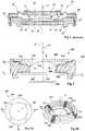
- Figure 1represents Figure 4 of European Patent Application EP 1662276 , and illustrates a variable focus lens 10 according to one example of the prior art.
- Lens 10comprises two transparent windows 12, 14, arranged in parallel and facing each other, and delimiting, in part, an internal volume 15 containing two immiscible liquids 16, 18, with different optical indices. Where the two liquids meet they form an optical interface 19 in the form of a meniscus, which can have a number of different shapes, examples being shown by lines A and B.
- the liquids 16, 18have substantially equal densities, and one is preferably an insulating liquid, for example comprising oil and/or an oily substance, and the other is preferably a conductive liquid comprising for example an aqueous solution.
- Windows 12, 14are preferably transparent plates formed of an optical transparent material such as glass.
- the structure of the lens 10 that contains the liquidscomprises a cap 20 to which transparent window 12 is fixed, for example by glue 21, and a body 22 to which transparent window 14 is fixed, for example by glue 23.
- the cap 20 and body 22are separated by a gasket 24.
- Cap 20comprises a substantially cylindrical side wall 26, while body 22 comprises a substantially cylindrical side wall 27, and gasket 24 is positioned between the side walls 26 and 27, to ensure the tightness of the lens structure.
- Cap 20 and body 22 in this exampleform electrodes of the lens.
- Cap 20is used to provide a voltage to the conductive liquid 18.
- Body 22is used to provide a voltage close to the edge of the liquid-liquid interface 19.
- the edge of the liquid-liquid interface 19contacts an insulated conical surface 26 of the annular body.
- the parts of body 22 in contact with the liquids 16, 18, including conical surface 26,are coated with an insulating layer (not shown).
- the interface 19traversed an opening in the annual body 22 through which light rays can pass.
- the interfacemay be changed from initial concave shape shown by dashed line A, to a convex shape as shown by solid line B.
- dashed line Ainitial concave shape
- solid line Bconvex shape
- image stabilization techniquescan be used. This can be achieved by sensing the motion of the camera, and tilting one or more lenses in the camera to counteract this movement. It has been proposed to provide an electrowetting lens similar to lens 10 in which the tilt of the interface between the liquids in the lens is controlled by electrowetting by applying different voltages to one side of the lens than the other, the voltages for example being applied to a segmented electrode.
- US 2004/0227838A1relates to an image pickup apparatus comprising, inter alia, a refracting power-variable optical element comprising a first fluid member; a second fluid member; a shell member; a first electrode contacting the first fluid member; a second electrode installed at the shell member; and an electric voltage-supplying device to change a shape of the second fluid member in the shell member by changing a wetting property of the shell member for the second fluid member by supplying an electric voltage between the first fluid member and the shell member.
- a refracting power-variable optical elementcomprising a first fluid member; a second fluid member; a shell member; a first electrode contacting the first fluid member; a second electrode installed at the shell member; and an electric voltage-supplying device to change a shape of the second fluid member in the shell member by changing a wetting property of the shell member for the second fluid member by supplying an electric voltage between the first fluid member and the shell member.
- variable focus and image stabilizationare desired at the same time. While separate liquid lenses could be used for each of these functions, such a solution is disadvantageous due to its size. There is thus a need in the art for a solution that would allow both of these functions to be achieved by a single liquid lens.
- a method of controlling a liquid lens in an imaging devicecomprising: a liquid-liquid interface between first and second immiscible liquids deformable by electrowetting; a chamber containing the first and second liquids, the first liquid being an insulating liquid and the second liquid being a conducting liquid; and a first electrode in contact with the second liquid and at least one second electrode insulated from the second liquid by an insulating layer, the first and second electrodes being arranged to allow a plurality of voltages levels to be applied between the first and second electrodes to control the shape of the liquid-liquid interface, the method comprising: determining motion data indicating a movement of the imaging device using a motion detector; determining a focusing signal indicating a desired focus of the imaging device using a focus determination block; determining the plurality of voltage levels to be applied between the first and second electrodes, wherein each of the voltage levels is a function of the motion data, the focusing signal and constants relating to the physical properties of
- the step of determining the plurality of voltage levelscomprises calculating each of the voltages levels based on the product of the motion data and a first parameter relating to the liquid lens and preliminary determined in a calibration phase and the product of the focusing data and a second parameter relating to the liquid lens and preliminary determined in a calibration phase.
- the motion datacomprises first and second values indicating a shift in first and second dimensions respectively of an image formed on an image sensor of the imaging device, and wherein determining the plurality of voltage levels comprises determining at least one of the voltage levels based on both of the first and second values.
- determining the plurality of voltage levelscomprises determining at least one of the voltage levels based on a function having a term dependent on the product of the first and second value of the motion data.
- the functionis a square root function.
- the motion datacomprises at least one value indicating a shift in a first dimension of an image formed on an image sensor of the imaging device, the at least one value further indicating whether the shift is in a first direction or a second direction opposite to the first direction, and wherein determining the plurality of voltage levels comprises multiplying the at least one value by a first constant if the shift is in the first direction, and multiplying the at least one value by a second constant if the shift is in the second direction.
- determining the plurality of voltage levelscomprises determining at least one of the voltage levels based on a function having a term comprising the product of the motion data and the focusing data.
- determining the plurality of voltage levelscomprises calculating the voltage values based on astigmatism data indicating a level of astigmatism to be applied to the lens.
- an imaging devicecomprising: a liquid lens comprising: a liquid-liquid interface between first and second immiscible liquids deformable by electrowetting; a chamber containing the first and second liquids, the first liquid being an insulating liquid and the second liquid being a conducting liquid; and at least one first electrode in contact with the second liquid and at least one second electrode insulated from the second liquid by an insulating layer, the first and second electrodes being arranged to allow a plurality of voltages levels to be applied between the first and second electrodes to control the shape of the liquid-liquid interface; a motion detector for determining motion data indicating a movement of said imaging device; a focus determination block for determining a focusing signal indicating a desired focus of said imaging device; a processor arranged to receive said motion data and said focusing signal, and to determining the plurality of voltage levels based on the motion data, the focusing signal and constants relating to the physical properties of the liquid lens, wherein said constants are prelimin
- the liquid lenscomprises a plurality of second electrodes, each of the plurality of voltage levels being applied between the first electrode and one of the plurality of second electrodes.
- the motion datacomprises first and second values indicating a shift in first and second dimensions respectively of an image formed on an image sensor of the imaging device, and wherein determining the plurality of voltage levels comprises determining at least one of the voltage levels based on the first and second values.
- determining the plurality of voltage levelscomprises determining at least one of the voltage levels based on a function having a term dependent on the product of the first value and second values of the motion data.
- the functionis a square root function.
- determining the plurality of voltage levelscomprises determining at least one of the voltage levels based on a function having a term dependent on the product of the motion data and the focusing data.
- the second electrodecomprises an annular body formed of a material having a conductivity in the range 10 4 to 10 7 Ohm.cm.
- the constantsare preliminary determined in a calibration phase comprising successive steps of varying the plurality of voltages until a determined focus is achieved; applying a voltage change to at least one of the plurality of voltage levels to cause a change in tilt of the liquid-liquid interface in a first direction; varying at least one of the plurality of voltage levels to cause a change of the shape of the liquid-liquid interface until the determined focus is achieved again and until an astigmatism lower to a given value is achieved; and measuring the extent of the tilt to determine the at least one predetermined parameter.
- a mobile telephonecomprising an image sensor, a processor, a display, and the above imaging device.
- a digital cameracomprising an image sensor, a processor, and the above imaging device.
- a method of calibrating the above imaging devicecomprising the successive steps of varying the plurality of voltages until a determined focus is achieved; applying a voltage change to a first one of the plurality of voltage levels applied at a first side of the liquid-liquid interface to cause a change in tilt of the liquid-liquid interface in a first direction; varying a second one of the plurality of voltage levels applied to a second side of the liquid-liquid interface opposite to the first side to cause a change in tilt of the liquid-liquid interface in the first direction until the determined focus is achieved again; and measuring the extent of the tilt to determine the at least one predetermined parameter.
- Figure 2is a cross-section view schematically illustrating a liquid lens 200, and showing how a tilt and focus can be achieved by application of different voltages V1 and V2 to an electrode 202.
- Liquid lens 200is mounted over an image sensor 201, for example with one or more fixed lenses positioned between the liquid lens 200 and the image sensor (fixed lenses not shown in Figure 2 ).
- Lens 200comprises an annular body 202, having an insulating layer 204 covering its inner surfaces, such that it is insulated from the liquids in the lens.
- Transparent windows 206, 208are glued to an underside and a top side respectively of the annular body 202, sealing an insulating liquid 210 and a conducting liquid 212 in the lens. These liquids have different refractive indices, and form an optical interface 214 in the form of a meniscus where they meet.
- the annular body 202either comprises a segmented electrode or a resistive body, such that when two different voltages V1 and V2 are applied to opposite sides of the annular body, different voltages are generated close to the edge of interface 214 on each side of the lens, causing the liquid interface to tilt.
- the voltagesare applied between the annular body 202 and an electrode 216 contacting the conducting liquid.
- a liquid lens with resistive bodyis for example discussed in more detail in co-pending European Application 07301180.1 , in the name of the present applicant.
- the exampleis shown in which voltage V1 applied to the left-hand side of the body 202 is higher than voltage V2 applied to the right-hand side of the body.
- the higher voltage provided to the left-hand sidecauses a larger displacement of the edge of the liquid interface 214 on the left hand side of the lens than the displacement on the right-hand side.
- the normal optical axis ⁇ of refractive interface 214extends through a central axis of the lens, perpendicular to windows 206, 208, the new optical axis ⁇ ' of the tilted refractive interface is inclined by an angle ⁇ to the normal optical axis ⁇ .
- Angle ⁇is for example controllable in a range from 0-30° by the difference between V1 and V2.
- Angle ⁇ for a given cross-section of the lenscan be determined approximately as half the difference in contact angle between the edge of the liquid interface 214 with conical surface 218 of the annular body 202 in contact with the liquid interface. Assuming a contact angle ⁇ between interface 214 and surface 218 in the region of voltage V1, and a contact angle ⁇ between interface 214 and surface 204 in the region of voltage V2, angle ⁇ can be determined as approximately equal to ( ⁇ - ⁇ )/2. This represents the geometric tilt of a refractive interface.
- the effective optical tiltcan be approximately determined as:
- Optical TiltGeometric Tilt . ⁇ n where ⁇ n is the refractive index of insulating liquid 210 minus that of conducting liquid 212.
- Focusing of the lensin other words the power of the lens resulting from the curvature of the interface 214, is controlled at the same time as the tilt of the lens.
- the power of the lensis at least dependent on the average of voltages V1 and V2, whereas the tilt is at least dependent on the difference between V1 and V2.
- the voltage levels to be applied to the liquid lens to achieve different levels of tilt and focuscan vary due to the physical properties of the lens, and in particular small imperfections in the contact surface 218 of the annular body 202 in contact with the edge of interface 214 or transfer rate as explained below.
- focus and tiltcan be interdependent.
- lens 200has been described as being controlled by different voltages applied to the annular body, in alternative embodiments, only one voltage could be applied to the body, and additional electrodes, such as electrode 220 illustrated by a dashed line in Figure 2 , could be added to make contact with the liquid 212.
- liquid 212is preferably partially resistive, such that a voltage gradient is present in liquid.
- the voltageis not always applied very close to the inner edge 218 of the annular body. Since the voltage difference applied to the plurality of contacts induces a voltage gradient within the resistive body or resistive liquid, the effective voltage at the inner edge 218 will be reduced versions of the applied voltages, depending on the distance between inner edge 218 and the contacts. Therefore, there is also a transfer rate between the applied voltage and the effective voltage. Such a transfer rate should also be taken into account when determining the levels of voltages to be applied in order to get a desired value of tilt and focus.
- Figure 3Aillustrates in plan view an electrode 300 of the lens, for example forming part of the annular body of the liquid lens, or being in contact with the conducting liquid of the lens.
- Figure 3Ashows a segmented electrode in the form of an annular disc divided equally into four segments 301 to 304, each segment being separated from the next by a gap. Segments 301 to 304 receive respective voltages Vx+, Vy-, Vx- and Vy+.
- Figure 3Bis in an elevated view of the underside of a resistive annular body 310 forming an electrode of the lens, and for example having a relatively low conductance when compared to the segments of Figure 3A .
- the annular body 310is for example formed of a moulded polymer material, such as a liquid crystal polymer, having a conductivity in the range 10 4 to 10 7 Ohm.cm.
- Four contacts 311 to 314are provided on the surface of the annular body 310, for example formed of a metal having a relatively high conductivity such as copper. These contacts are provided in the form of four conductive tracks equally spaced around the annular body.
- each trackextends, on the top and bottom sides of the annular body, radially inwardly from the outer edge of the body 310 to points close to the inner edge of the annular body.
- Voltages Vx+, Vy-, Vx- and Vy+are applied to the contacts 311 to 314 respectively, such that when Vx+, Vy-, Vx- and Vy+ are different from each other, corresponding different voltage levels are present at the inner edge of the annular body.
- circuitry for generating voltages Vx+, Vy-, Vx- and Vy+ for application to the electrodes/contacts of Figures 3A or 3Bwill be described. It will be apparent that this circuitry could be extended to provide more than four voltages in cases in which more than four electrodes/contacts are provided. For example a total of six, eight or twelve electrodes/contacts and corresponding voltages could be provided, allowing a finer control of the liquid interface.
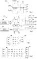
- Figure 4illustrates control circuitry 400 of an imaging device comprising a processing block 402, which receives a focus signal indicating a desired focus of the liquid lens, and inputs ⁇ x and ⁇ y indicating a movement of the imaging device. Based on these inputs and a number of constants, for example stored in memory, block 402 generates signals for controlling the voltage levels to each of the electrode contacts of the liquid lens to provide image stabilization, counteracting the detected movement of the lens, at the same time as focusing, based on the focusing signal. In this example there are four electrode contacts and therefore four output signals from processing block 402.
- the outputs of block 402are provided to a driver 404 which generates the drive voltages to each of the electrode contacts of the liquid lens, based on the control signals from processing block 402.
- the driveroutputs voltages Vx+, Vx-, Vy+ and Vy-. These voltage levels for example correspond to amplitude levels of the voltage signal, which could be oscillating or fixed voltages. Alternatively, the voltage levels could be RMS values of oscillating voltages having fixed amplitudes.
- Figure 5illustrates circuitry 500 for generating the voltages Vx+, Vx-, Vy+ and Vy- according to one embodiment.
- Circuitry 500comprises a motion detector 502, and a focus determination block 504.
- Motion detector 502generates an indication the pitch and yaw of an imaging device.
- Yawis rotation of the imaging device around a vertical axis such the field of view moves to one side or the other, and will be referred to herein as ⁇ x.
- Pitchis the rotation of the imaging device around a horizontal axis such that the field of view moves upwards or downwards, and will be referred to herein as ⁇ y.
- the motion detectorfor example comprises a gyroscope sensor or an accelerometer for detecting and outputting ⁇ x and ⁇ y, or alternatively uses image analysis of the image or part of the image formed on the image sensor.
- ⁇ x and ⁇ yare values that are equal to zero if no yaw or pitch respectively is present, and have a positive value to represent pitch or yaw in one direction, and a negative value to represent pitch or yaw in the opposite direction.
- the values of ⁇ xprovide the tilt to be generated using Vx+ and Vx-, and for example if ⁇ x is positive, Vx+ is higher than Vx-, and vice versa.
- the values of ⁇ yprovide the tilt to be generated using Vy+ and Vy-, and for example if ⁇ y is positive, Vy+ is higher than Vy-, and vice versa.
- the focus determination block 504for example determines a focus signal based on a manual control made by the user of the imaging device, or automatically, for example using an autofocus sensor, or based on image analysis of the image or part of the image formed on the image sensor. Focus determination block outputs a focus signal representative of the desired focus.
- the ⁇ x and ⁇ y outputs of the motion detectorare provided to a tilt x block 506 and a tilt y block 508 respectively, and these blocks each generate voltage levels based on values ⁇ x and ⁇ y multiplied by respective constants ⁇ 1 and ⁇ 2.
- the output of block 506is provided to one of two inputs of an adder 510, and to the subtrahend input of a subtractor 512.
- the output of block 508is provided to one of two inputs of an adder 514, and to the subtrahend input of a subtractor 516.
- the focus output from the focus determination blockis provided to a focus block 518, which generates a voltage signal based on a multiplication of the focus output by a constant ⁇ .
- the focus signalis a relatively low voltage representing a required voltage, for example in a range 0 to 2 V, and ⁇ has a relatively high value for example of between 25 and 50 to generate the desired voltage level.
- the focus signalcould be a voltage level already amplified to be close to the final voltage level to be applied to the lens, and the value of ⁇ is close to 1, providing small variations in the voltage.
- the output of focus block 518is provided to the second input of adders 510, 514, and to the minuend input of adders 512, 516.
- the outputs of adder 510 and subtractor 512are amplified by respective amplifiers 520 and 522 to provide output voltages Vx+ and Vx- respectively, which are applied to opposite sides of the liquid lens to generate tilt of the liquid interface to counteract yaw.
- Adder 514 and subtractor 516are amplified by respective amplifiers 524 and 526 to provide output voltages Vy+ and Vy- respectively, which are applied to opposite sides of the liquid lens to counteract pitch.
- the orientation of the electrodes/electrode contacts for voltages Vx+, Vx-, Vy+, Vy-should be arranged to correspond to the orientation of the motion sensor.
- the values of constants ⁇ 1, ⁇ 2 and ⁇are determined during a calibration phase, which could be performed for individual lenses or alternatively for a batch of liquid lenses manufactured at the same time.
- calibration during the calibration phasecomprises initially setting all of the voltages Vx+, Vx-, Vy+, Vy- to the same value, and varying them together, for example in 1 volt steps, until a determined focus level, for example infinity focus, is achieved by the lens. This voltage is used to determine ⁇ , which can be calculated as the determined voltage level divided by the focus signal associated with the achieved focus.
- the level of one of the voltagesfor example Vx+
- Vx-the opposite voltage
- the opposite voltagein this case Vx-
- the level of tilt at these voltagescan then be measured, and used to determine constant ⁇ 1, or alternatively the process can be repeated, by reducing Vx- and increasing Vx+, the results are averaged and used to determine constant ⁇ 1.
- ⁇ 1is determined as the average voltage change divided by the tilt signal ⁇ x associated with the measured tilt.
- the same processis repeated for voltages Vy+ and Vy- to give constant ⁇ 2.
- a number of different testscan be performed, and the results averaged.
- Figure 6shows a reference matrix 600 and an input matrix 602, representing calculation of voltages Vx+, Vx-, Vy+ and Vy-.
- Matrix 600is a 3 by 4 matrix
- matrix 602is a 1 by 3 matrix, and when these are multiplied, the result is a 1 by 4 matrix containing the four voltages.
- Matrix 600is based on an ideal case that takes into account a homogeneous transfer rate of the body 202 of the lens 200.
- Figure 7shows a reference matrix 700 and an input matrix 702, representing calculation of voltages Vx+, Vx-, Vy+ and Vy- according to another embodiment in which irregularities between a tilt of the liquid interface in one direction and a tilt of the liquid interface in the opposite direction can be taken into account.
- the transfer rate between the desired focus or tilt and each voltage to be appliedcan be non-symmetrical.
- inducing a tilt in one directioncould require different voltages than inducing a tilt in the opposite direction.
- the embodiment of Figure 7provides a solution.
- the tilt values ⁇ x and ⁇ yare each separated into positive and negative components ⁇ x+, ⁇ x- and ⁇ y+, ⁇ y-respectively.
- ⁇ x and ⁇ yare positive if tilt is in a first direction, and negative if tilt is in the opposite direction, and ⁇ x+ and ⁇ y+ provide the tilt values if tilt is in the first direction, while ⁇ x- and ⁇ y- are zero, and ⁇ x- and ⁇ y-provide the tilt values if tilt is in the opposite direction, while ⁇ x+ and ⁇ y+ are zero.
- the values ⁇ x+ and ⁇ x-are multiplied by respective constants ⁇ 11 and - ⁇ 12 for calculation of Vx+, and by respective constants - ⁇ 21 and ⁇ 22 for calculation of Vx-. Given that one of ⁇ x+ and ⁇ x- is always zero, one of these multiplications will always result in zero.
- the values ⁇ y+ and ⁇ y-are multiplied by respective constants ⁇ 33 and - ⁇ 34 for calculation of Vy+, and by respective constants - ⁇ 43 and ⁇ 44 for calculation of Vy-. Again, given that one of ⁇ y+ and ⁇ y- is always zero, one of these multiplications will always result in zero.
- a further set of constants ⁇ 1 to ⁇ 4are used, multiplied by an astigmatism signal Astig to be applied to the lens.
- Astigmatism in a liquid lenscan be controlled by applying a higher voltage to two opposing electrodes than is applied to the other two opposing electrodes.
- Astigmatismis characterized by a difference of curvature radii of the interface in two perpendicular directions. In image stabilization applications, astigmatism is an optical aberration that should generally be minimized.
- astigmatismis likely to be the predominant non-spherical deformation of the liquid interface.
- the Astig signalcan be used to reduce astigmatism to zero. Alternatively, it is used to generate a desired deformation, which can be of use in some optical applications.
- a voltage adjustment of Astig. ⁇ 1is added in Vx+
- Astig. ⁇ 2is added in Vx-
- Astig. ⁇ 3is subtracted in Vy+
- Astig. ⁇ 4is subtracted in Vy-.
- the signal Astigis for example a signal having a positive or negative value, which is generated internally, and expresses the extent of desired deformation of the refractive interface.
- constants ⁇ 1 to ⁇ 4in some embodiments could be equal to each other, or different allowing unsymmetrical features in the lens to be taken into account.
- the values of constants ⁇ 1 to ⁇ 4can be calibrated during a calibration phase of the lens, for example by applying zero tilt and a predetermined focus to the interface, and increasing the voltage applied to opposing electrodes until a desired deformation is achieved.
- the constants of the reference matrix 700 of Figure 7are for example calibrated in a similar fashion to constants ⁇ 1, ⁇ 2 and ⁇ described above, although in this embodiment the results recorded from tilts in each direction are not averaged, but are used to determine the constants associated with each direction of tilt.
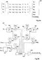
- Figure 8Ais a matrix representing calculation of voltages Vx+, Vx-, Vy+, Vy- according a different method in which the voltages are calculated based on a term ⁇ .focus. ⁇ max, where ⁇ is a constant and ⁇ max is the highest tilt of ⁇ x+, ⁇ x-, ⁇ y+, ⁇ y-, as a positive magnitude.
- any interdependency between tilt and focuscan be taken into account.
- the focus of the lensis degraded, and thus a higher voltage is needed to generate the same focus from the lens than is needed for lower tilts.
- different constants relating to the tiltcan be provided for each direction, in some cases there is not a linear relationship between voltage and tilt for a given focus, and in this case, a term comprising both tilt and focus provides a better model.
- the voltage for a particular electrodemay be dependent on the tilt voltage applied to each other electrode. This allows the voltages of the lens to be better adapted for a particular tilt. For example, it is possible that if a tilt in the x direction is made by a variation between voltages Vx+ and Vx-, a better curvature of the interface can be achieved when at the same time an offset is added to the voltages Vy+ and Vy-.
- FIG 8Bschematically illustrates control circuitry 800 implementing the calculation of voltages Vx+, Vx-, Vy+, Vy- according to the method represented by the matrix of Figure 8 .
- the circuitrycomprises a tilt x block 803, which receives ⁇ x as an input and outputs ⁇ x+ and ⁇ x-, and a tilt y block 804, which receives ⁇ y as an input and outputs ⁇ y+ and ⁇ y-.
- Values ⁇ x+, ⁇ x-, ⁇ y+ and ⁇ y-are provided to respective multipliers 806, 808, 810 and 812.
- each multiplier 806 to 812performs four multiply operations, multiplying the input values by the four constants shown in the first four columns of Figure 7 .
- the sets of four constantsare labelled ⁇ a1, ⁇ a2, ⁇ a3 and ⁇ a4, wherein a is equal to 1 to 4.
- each multipliergenerates four outputs in parallel or in series, one associated with each voltage to be generated.
- the focus valueis provided to multipliers 814 and 816.
- focusis multiplied by constant ⁇ .
- focusis multiplied by ⁇ max, which is generated by block 818 based on received values of ⁇ x and ⁇ y.
- the output of multiplier 816is provided to a further multiplier 820, which multiplies it by constant ⁇ .
- input value Astigis provided to a multiplier 822, where four multiply operations are performed to multiply Astig by each of the constants ⁇ 1 to ⁇ 4 to generate four outputs.
- multipliers 806, 808, 810, 812 and 822are added to the outputs of multipliers 814 and 820 by adder block 824, to generate the voltages Vx+, Vx-, Vy+, Vy- respectively, which are output by driving circuitry 826 connected to adder 824.
- Determination of the constants of the matrix of Figure 8Acan be achieved during a calibration step in which more detailed analysis of the effects of changes in the voltages is observed.
- the values for tiltare determined in a similar fashion to the methods described above, except that, once Vx+ and Vx- have been determined for a given tilt, small variations to Vy+ and Vy- are made and image analysis performed to determine whether an improved image quality can be achieved.
- To determine the value of ⁇determined values for the tilt signals and focus signal are for example applied and then the effect on the focus of a change to the focus signal is observed. This is repeated for a number of different values of tilt, using the same change in focus signal, and if the effect on the focus varies, this implies an interdependence between tilt and focus which can be corrected by introducing a corresponding value for ⁇ .
- FIG 9is a schematic view of an optical apparatus 900 including an optical device according to embodiments of the invention, which is for example to be used in a compact digital camera, mobile phone, or alternative electronic/optical device.
- Optical apparatus 900comprises a camera module 902 comprising a lens arrangement 903 and an optical device 904 according to one of the embodiments described herein.
- Optical device 904has four contacts 905 to 908 for connecting four voltages, either to separate electrodes as illustrated in Figure 3A , or a resistive electrode as illustrated in Figure 3B . More contacts could be provided in alternative embodiments, and more corresponding voltages could be generated. At least one further electrode 909 is provided for making contact with the conducting liquid in the lens.
- the lens arrangement 903comprises a number of fixed lenses. It will be apparent that in alternative embodiments the four contacts could be connected to corresponding electrodes in contact with the conducting liquid, and a single contact made with the body of the lens.
- Driving circuitry 916is provided connected to the contacts 905 to 908 and electrode 909. The driving circuitry 916 generates oscillating voltage signals to each of the electrodes.
- the driving circuitry 916for example comprises one or more frequency oscillators for generating signals at one or more given frequencies. These signals can then be amplified before being provided between contacts 905 to 908 and electrode 909.
- the voltages applied between electrode 908 and contacts 905 to 908can have different voltage levels or RMS values. This can for example be achieved by providing a variable resistor connected in series between the voltage signal and each of the contacts on the electrodes, so that the peak to peak voltage level can be varied independently, for example from 0V to 120V. Alternatively, identical voltage signals having the same peak to peak voltage value, the same period and the same RMS voltage can be applied to the electrodes at the same time, but a variable delay can be added to the signal applied to each of the contacts.
- the RMS voltagecan be varied anywhere between 0V, when the signals applied to electrode 909 and one of the contacts 905 to 908 are exactly in phase, and a maximum value when the voltage signals are exactly 180 degrees out of phase of 60V RMS.
- Such delayscan for example be provided by capacitors.
- the RMS voltage of the signal to each of the contacts 905 to 908can be varied by varying the duty cycle of each of these signals, while providing either 0V or a signal having a constant duty circle to the electrode 909, to give RMS voltages variable between 0 and 60 V.
- each of the contacts 905 to 908is supplied in turn with an AC voltage signal.
- the time during which the voltage signal is appliedis varied for each contact so that the required voltage is applied.
- the time period during which each contact 905 to 908 is not connected to the AC voltage signalis preferably shorter than the response time of a liquid liquid interface so that there is no undesired movement of interface.
- the camera module 902further comprises an image sensor 912 which captures images formed from light rays received by optical device 904 and fixed lenses 903.
- a processing unit 914is provided in the optical apparatus 900, which is for example an image signal processor or a base band processor of a mobile phone. Processing unit 914 performs the calculation of the voltage levels as described above, and these values are provided to the driving circuitry 916. Processing unit 914 receives captured images from image sensor 912 and stores them in a memory 918 and/or displays them on a display 920.
- a power supply unit 924provides supply voltages to the driving circuitry 916, the image sensor 912 and the processing unit 914
- a motion sensor 926is be provided, connected to the processing unit 914, which generates signals ⁇ x and ⁇ y.
- movement of the apparatus around other axiscould be detected by the motion detector, and corresponding additional electrodes provided in the liquid lens to control the tilt of the lens in response to the motion.
- Motion sensor 926can comprise any suitable means for detecting motion of the apparatus, such as a micro-electro-mechanical system (MEM) accelerometer, or gyroscope.
- MEMmicro-electro-mechanical system
- gyroscopegyroscope
- a calibration loopcould be provided to calibrate the tilt before a picture is taken.
- motioncan be detected for example using the motion sensor 926, the image can be tilted in response to account for the motion, and the image from the image sensor can be used to determine if the correct tilt was applied based on the motion.
- this informationcan be used to recalibrate the tilt applied for a given movement for future movements, by adjusting the constants ⁇ described above.
- control circuitrywhich advantageously allows the tilt of a liquid interface of a liquid lens to be controlled at the same time as its focus. This is achieved by generating the voltages to be applied to multiple contacts of the lens based on motion detected by a motion detector, focusing information and at least one constant. Preferably, the voltages are determined based on the product of said focusing information and a first constant, and the product of said motion and a second constant. These constants are for example determined during a calibration phase, executed at the manufacturing stage of the liquid lens, for example prior to assembly of device 902.
- Figure 10shows a matrices system according to another embodiment of the present invention enabling to minimize astigmatism and loss of focus.
- ⁇ x and ⁇ y of the input matrix 1020correspond to motion data of the imaging device.
- the root term of matrix 1020 combining ⁇ x and ⁇ y motion dataallows the tilt of the liquid interface to be accurately modeled, in particular when the tilt is done in both x and y directions at once, defined by the variation between voltages (Vx+, Vx-) and (Vy+, Vy-) respectively. This term enables to take into account the coupling between two adjacent electrodes, which is a crosstalk-like phenomenon that can lead to a loss of focus and/or to astigmatism.
- the values of constants a to l and ⁇ of the referenced matrix 1000are determined during a calibration phase, which could be performed for individual lenses or alternatively for a batch of liquid lenses manufactured at the same time.
- calibration during the calibration phasecomprises initially setting all of the voltages Vx+, Vx-, Vy+, Vy- to the same value, and varying them together, for example in 1 volt steps, until a determined focus level, for example infinity focus, is achieved by the lens.
- the voltage of this reference pointis used to determine ⁇ , which can be calculated as the determined voltage level divided by the focus signal associated with the achieved focus.
- the level of two voltagesfor example the two opposite voltages Vx+ and Vx-
- oneis increased and one is reduced by a given step, causing a tilt in one direction, in this case the x direction.
- this tilt of the liquid-liquid interfacecan create a loss of focus and an increase of astigmatism.
- all of the voltages Vx+, Vx-, Vy+, Vy-are increased by a given step, until focus is achieved again.
- two opposite voltagesfor example Vx+ and Vx-
- Vx+ and Vx-are increased while the other two opposite voltages, for example Vy+ and Vy-, are decreased, until astigmatism is lower to a given value.
- the level of tilt at these voltagescan then be measured, and used to determine a constant associated to each of the voltages Vx+, Vx-, Vy+ and Vy-.
- the processcan be repeated, by modifying the voltage step which induces the tilt, for example Vx+ and Vx-, the results are averaged and used to determine a constant associated with each of the voltages Vx+, Vx-, Vy+ and Vy-.
- the processis also repeated in order to obtain tilt data and associated voltages in several directions, for example in y direction by varying Vy+ and Vy- and in an intermediate direction to x and y by increasing two adjacent voltages, for example Vx+ and Vy-, and decreasing the other two adjacent voltages Vx- and Vy+ by a given step.
- Thisallows to estimates all the constants a to 1 of the referenced matrix 1000. It will be apparent for the man skilled in the art that other methods than the above described example of determination of matrix 1000 can be used.
- a systemcould calculate the voltage levels based on the matrix of Figure 6 , and additionally comprising astigmatism control described in relation to Figure 7 using one or more ⁇ constants, or comprising a term focus. ⁇ max using a ⁇ constant as described in relation to Figure 8A .
- the generation of the voltage levels to be applied to the lenscould be implemented in software or hardware or a combination of both.
- the methodcould be adapted to provide a lower or greater number of voltages or a lower or greater number of contacts.
- electrowetting device and control circuitrycould be incorporated in any optical system, for example in cameras, mobile telephones, ophthalmic tools, endoscopes, barcode readers, binoculars etc.
Landscapes
- Physics & Mathematics (AREA)
- Engineering & Computer Science (AREA)
- Multimedia (AREA)
- Signal Processing (AREA)
- General Physics & Mathematics (AREA)
- Optics & Photonics (AREA)
- Mechanical Light Control Or Optical Switches (AREA)
- Studio Devices (AREA)
Description
- The present invention relates to circuitry for controlling a liquid lens, and in particular to image stabilization circuitry for a liquid lens.
- Electrowetting devices, and in particular electrowetting lenses, are known in the art, and generally comprise a refractive interface between first and second immiscible liquids that is movable by electrowetting.
Figure 1 representsFigure 4 of European Patent ApplicationEP 1662276 , and illustrates avariable focus lens 10 according to one example of the prior art.Lens 10 comprises twotransparent windows internal volume 15 containing twoimmiscible liquids optical interface 19 in the form of a meniscus, which can have a number of different shapes, examples being shown by lines A and B. Theliquids - Windows 12, 14 are preferably transparent plates formed of an optical transparent material such as glass.
- The structure of the
lens 10 that contains the liquids comprises acap 20 to whichtransparent window 12 is fixed, for example byglue 21, and abody 22 to whichtransparent window 14 is fixed, for example byglue 23. Thecap 20 andbody 22 are separated by agasket 24.Cap 20 comprises a substantiallycylindrical side wall 26, whilebody 22 comprises a substantiallycylindrical side wall 27, andgasket 24 is positioned between theside walls - The
cap 20 andbody 22 in this example form electrodes of the lens.Cap 20 is used to provide a voltage to theconductive liquid 18.Body 22 is used to provide a voltage close to the edge of the liquid-liquid interface 19. The edge of the liquid-liquid interface 19 contacts an insulatedconical surface 26 of the annular body. The parts ofbody 22 in contact with theliquids conical surface 26, are coated with an insulating layer (not shown). Theinterface 19 traversed an opening in theannual body 22 through which light rays can pass. - Due to the electrowetting effect, it is possible, by applying a voltage between the
cap 20 and thebody 22, to change the positioning of the edge of the liquid-liquid interface on theconical surface 26, and thereby change the curvature of the refractive interface betweenliquids windows cap 20 andbody 22. - To avoid unwanted blurring of images captured by digital cameras caused by camera shake, image stabilization techniques can be used. This can be achieved by sensing the motion of the camera, and tilting one or more lenses in the camera to counteract this movement. It has been proposed to provide an electrowetting lens similar to
lens 10 in which the tilt of the interface between the liquids in the lens is controlled by electrowetting by applying different voltages to one side of the lens than the other, the voltages for example being applied to a segmented electrode. US 2004/0227838A1 relates to an image pickup apparatus comprising, inter alia, a refracting power-variable optical element comprising a first fluid member; a second fluid member; a shell member; a first electrode contacting the first fluid member; a second electrode installed at the shell member; and an electric voltage-supplying device to change a shape of the second fluid member in the shell member by changing a wetting property of the shell member for the second fluid member by supplying an electric voltage between the first fluid member and the shell member.- In many applications, variable focus and image stabilization are desired at the same time. While separate liquid lenses could be used for each of these functions, such a solution is disadvantageous due to its size. There is thus a need in the art for a solution that would allow both of these functions to be achieved by a single liquid lens.
- It is an aim of embodiments of the present invention to provide a lens that at least partially address one or more the prior art.
- The invention is defined by the appended claims.
- According to one aspect of the present invention, there is provided a method of controlling a liquid lens in an imaging device, the liquid lens comprising: a liquid-liquid interface between first and second immiscible liquids deformable by electrowetting; a chamber containing the first and second liquids, the first liquid being an insulating liquid and the second liquid being a conducting liquid; and a first electrode in contact with the second liquid and at least one second electrode insulated from the second liquid by an insulating layer, the first and second electrodes being arranged to allow a plurality of voltages levels to be applied between the first and second electrodes to control the shape of the liquid-liquid interface, the method comprising: determining motion data indicating a movement of the imaging device using a motion detector; determining a focusing signal indicating a desired focus of the imaging device using a focus determination block; determining the plurality of voltage levels to be applied between the first and second electrodes, wherein each of the voltage levels is a function of the motion data, the focusing signal and constants relating to the physical properties of the liquid lens, wherein said constants are preliminarily determined in a calibration phase; applying said plurality of voltage levels between said first and second electrodes.
- According to an embodiment of the present invention, the step of determining the plurality of voltage levels comprises calculating each of the voltages levels based on the product of the motion data and a first parameter relating to the liquid lens and preliminary determined in a calibration phase and the product of the focusing data and a second parameter relating to the liquid lens and preliminary determined in a calibration phase.
- According to another embodiment of the present invention, the motion data comprises first and second values indicating a shift in first and second dimensions respectively of an image formed on an image sensor of the imaging device, and wherein determining the plurality of voltage levels comprises determining at least one of the voltage levels based on both of the first and second values.
- According to another embodiment of the present invention, determining the plurality of voltage levels comprises determining at least one of the voltage levels based on a function having a term dependent on the product of the first and second value of the motion data.
- According to another embodiment of the present invention, the function is a square root function.
- According to another embodiment of the present invention, the motion data comprises at least one value indicating a shift in a first dimension of an image formed on an image sensor of the imaging device, the at least one value further indicating whether the shift is in a first direction or a second direction opposite to the first direction, and wherein determining the plurality of voltage levels comprises multiplying the at least one value by a first constant if the shift is in the first direction, and multiplying the at least one value by a second constant if the shift is in the second direction.
- According to the present invention, determining the plurality of voltage levels comprises determining at least one of the voltage levels based on a function having a term comprising the product of the motion data and the focusing data.
- According to another embodiment of the present invention, determining the plurality of voltage levels comprises calculating the voltage values based on astigmatism data indicating a level of astigmatism to be applied to the lens.
- According to another aspect of the present invention, there is provided an imaging device comprising: a liquid lens comprising: a liquid-liquid interface between first and second immiscible liquids deformable by electrowetting; a chamber containing the first and second liquids, the first liquid being an insulating liquid and the second liquid being a conducting liquid; and at least one first electrode in contact with the second liquid and at least one second electrode insulated from the second liquid by an insulating layer, the first and second electrodes being arranged to allow a plurality of voltages levels to be applied between the first and second electrodes to control the shape of the liquid-liquid interface; a motion detector for determining motion data indicating a movement of said imaging device; a focus determination block for determining a focusing signal indicating a desired focus of said imaging device; a processor arranged to receive said motion data and said focusing signal, and to determining the plurality of voltage levels based on the motion data, the focusing signal and constants relating to the physical properties of the liquid lens, wherein said constants are preliminarily determined in a calibration phase; and a drive circuitry arranged to apply the determined plurality of voltage levels between the first and second electrodes.
- According to an embodiment of the present invention, the liquid lens comprises a plurality of second electrodes, each of the plurality of voltage levels being applied between the first electrode and one of the plurality of second electrodes.
- According to another embodiment of the present invention, the motion data comprises first and second values indicating a shift in first and second dimensions respectively of an image formed on an image sensor of the imaging device, and wherein determining the plurality of voltage levels comprises determining at least one of the voltage levels based on the first and second values.
- According to another embodiment of the present invention, determining the plurality of voltage levels comprises determining at least one of the voltage levels based on a function having a term dependent on the product of the first value and second values of the motion data.
- According to another embodiment of the present invention, the function is a square root function.
- According to another embodiment of the present invention, determining the plurality of voltage levels comprises determining at least one of the voltage levels based on a function having a term dependent on the product of the motion data and the focusing data.
- According to another embodiment of the present invention, the second electrode comprises an annular body formed of a material having a conductivity in the
range 104 to 107 Ohm.cm. - According to another embodiment of the present invention, the constants are preliminary determined in a calibration phase comprising successive steps of varying the plurality of voltages until a determined focus is achieved; applying a voltage change to at least one of the plurality of voltage levels to cause a change in tilt of the liquid-liquid interface in a first direction; varying at least one of the plurality of voltage levels to cause a change of the shape of the liquid-liquid interface until the determined focus is achieved again and until an astigmatism lower to a given value is achieved; and measuring the extent of the tilt to determine the at least one predetermined parameter.
- According to another aspect of the present invention, there is provided a mobile telephone comprising an image sensor, a processor, a display, and the above imaging device.
- According to another aspect of the present invention, there is provided a digital camera comprising an image sensor, a processor, and the above imaging device.
- According to another aspect of the present invention, there is provided a method of calibrating the above imaging device comprising the successive steps of varying the plurality of voltages until a determined focus is achieved; applying a voltage change to a first one of the plurality of voltage levels applied at a first side of the liquid-liquid interface to cause a change in tilt of the liquid-liquid interface in a first direction; varying a second one of the plurality of voltage levels applied to a second side of the liquid-liquid interface opposite to the first side to cause a change in tilt of the liquid-liquid interface in the first direction until the determined focus is achieved again; and measuring the extent of the tilt to determine the at least one predetermined parameter.
- The foregoing and other purposes, features, aspects and advantages of the invention will become apparent from the following detailed description of embodiments, given by way of illustration and not limitation with reference to the accompanying drawings, in which:
Figure 1 (described above) is a cross-section view of a liquid lens according to the prior art;Figure 2 is a cross-section view of a liquid lens capable of variable focus and tilt according to an embodiment of the present invention;Figure 3A is a plan view of a segmented electrode according to one embodiment;Figure 3B is a plan view of a resistive electrode according to one embodiment;Figure 4 illustrates schematically control circuitry for generating voltages for driving a liquid lens according to a first embodiment of the present invention;Figure 5 illustrates schematically circuitry for generating voltages for driving a liquid lens according to another embodiment of the present invention;Figures 6 and 7 illustrate matrices used for generating voltage levels for driving a liquid lens according to embodiments of the present invention;Figure 8A illustrates matrices used for generating voltage levels for driving a liquid lens according to further embodiments of the present invention;Figure 8B illustrates schematically circuitry for generating voltages for driving a liquid lens according to a further embodiment of the present invention; andFigure 9 is a schematic illustration of an optical apparatus according to an embodiment of the present invention.Figure 10 illustrates matrices used for generating voltage levels for driving a liquid lens according to a further embodiment of the present invention.Figure 2 is a cross-section view schematically illustrating aliquid lens 200, and showing how a tilt and focus can be achieved by application of different voltages V1 and V2 to anelectrode 202.Liquid lens 200 is mounted over animage sensor 201, for example with one or more fixed lenses positioned between theliquid lens 200 and the image sensor (fixed lenses not shown inFigure 2 ).Lens 200 comprises anannular body 202, having an insulatinglayer 204 covering its inner surfaces, such that it is insulated from the liquids in the lens.Transparent windows annular body 202, sealing an insulatingliquid 210 and a conducting liquid 212 in the lens. These liquids have different refractive indices, and form anoptical interface 214 in the form of a meniscus where they meet.- The
annular body 202 either comprises a segmented electrode or a resistive body, such that when two different voltages V1 and V2 are applied to opposite sides of the annular body, different voltages are generated close to the edge ofinterface 214 on each side of the lens, causing the liquid interface to tilt. The voltages are applied between theannular body 202 and anelectrode 216 contacting the conducting liquid. A liquid lens with resistive body is for example discussed in more detail in co-pending European Application07301180.1 - The example is shown in which voltage V1 applied to the left-hand side of the
body 202 is higher than voltage V2 applied to the right-hand side of the body. As illustrated, due to the electrowetting effect, the higher voltage provided to the left-hand side causes a larger displacement of the edge of theliquid interface 214 on the left hand side of the lens than the displacement on the right-hand side. Whereas the normal optical axis Δ ofrefractive interface 214 extends through a central axis of the lens, perpendicular towindows - Angle µ is for example controllable in a range from 0-30° by the difference between V1 and V2. Angle µ for a given cross-section of the lens can be determined approximately as half the difference in contact angle between the edge of the
liquid interface 214 withconical surface 218 of theannular body 202 in contact with the liquid interface. Assuming a contact angle ρ betweeninterface 214 andsurface 218 in the region of voltage V1, and a contact angle ϕ betweeninterface 214 andsurface 204 in the region of voltage V2, angle µ can be determined as approximately equal to (ρ - ϕ)/2. This represents the geometric tilt of a refractive interface. The effective optical tilt can be approximately determined as:
liquid 210 minus that of conductingliquid 212. - Focusing of the lens, in other words the power of the lens resulting from the curvature of the
interface 214, is controlled at the same time as the tilt of the lens. The power of the lens is at least dependent on the average of voltages V1 and V2, whereas the tilt is at least dependent on the difference between V1 and V2. However, as will be explained in more detail below, the voltage levels to be applied to the liquid lens to achieve different levels of tilt and focus can vary due to the physical properties of the lens, and in particular small imperfections in thecontact surface 218 of theannular body 202 in contact with the edge ofinterface 214 or transfer rate as explained below. Furthermore, focus and tilt can be interdependent. - While the
lens 200 has been described as being controlled by different voltages applied to the annular body, in alternative embodiments, only one voltage could be applied to the body, and additional electrodes, such aselectrode 220 illustrated by a dashed line inFigure 2 , could be added to make contact with the liquid 212. In this case, liquid 212 is preferably partially resistive, such that a voltage gradient is present in liquid. Such an embodiment is discussed in more detail in co-pending European Application no.06301000.3 - In the case of a resistive body or the use of a
resistive liquid 212, the voltage is not always applied very close to theinner edge 218 of the annular body. Since the voltage difference applied to the plurality of contacts induces a voltage gradient within the resistive body or resistive liquid, the effective voltage at theinner edge 218 will be reduced versions of the applied voltages, depending on the distance betweeninner edge 218 and the contacts. Therefore, there is also a transfer rate between the applied voltage and the effective voltage. Such a transfer rate should also be taken into account when determining the levels of voltages to be applied in order to get a desired value of tilt and focus. Figure 3A illustrates in plan view anelectrode 300 of the lens, for example forming part of the annular body of the liquid lens, or being in contact with the conducting liquid of the lens. In particular,Figure 3A shows a segmented electrode in the form of an annular disc divided equally into foursegments 301 to 304, each segment being separated from the next by a gap.Segments 301 to 304 receive respective voltages Vx+, Vy-, Vx- and Vy+.Figure 3B is in an elevated view of the underside of a resistiveannular body 310 forming an electrode of the lens, and for example having a relatively low conductance when compared to the segments ofFigure 3A . Theannular body 310 is for example formed of a moulded polymer material, such as a liquid crystal polymer, having a conductivity in therange 104 to 107 Ohm.cm. Fourcontacts 311 to 314 are provided on the surface of theannular body 310, for example formed of a metal having a relatively high conductivity such as copper. These contacts are provided in the form of four conductive tracks equally spaced around the annular body. As illustrated, each track extends, on the top and bottom sides of the annular body, radially inwardly from the outer edge of thebody 310 to points close to the inner edge of the annular body. Voltages Vx+, Vy-, Vx- and Vy+ are applied to thecontacts 311 to 314 respectively, such that when Vx+, Vy-, Vx- and Vy+ are different from each other, corresponding different voltage levels are present at the inner edge of the annular body.- In the following, circuitry for generating voltages Vx+, Vy-, Vx- and Vy+ for application to the electrodes/contacts of
Figures 3A or 3B will be described. It will be apparent that this circuitry could be extended to provide more than four voltages in cases in which more than four electrodes/contacts are provided. For example a total of six, eight or twelve electrodes/contacts and corresponding voltages could be provided, allowing a finer control of the liquid interface. Figure 4 illustratescontrol circuitry 400 of an imaging device comprising aprocessing block 402, which receives a focus signal indicating a desired focus of the liquid lens, and inputs θx and θy indicating a movement of the imaging device. Based on these inputs and a number of constants, for example stored in memory, block 402 generates signals for controlling the voltage levels to each of the electrode contacts of the liquid lens to provide image stabilization, counteracting the detected movement of the lens, at the same time as focusing, based on the focusing signal. In this example there are four electrode contacts and therefore four output signals from processingblock 402.- The outputs of
block 402 are provided to adriver 404 which generates the drive voltages to each of the electrode contacts of the liquid lens, based on the control signals from processingblock 402. The driver outputs voltages Vx+, Vx-, Vy+ and Vy-. These voltage levels for example correspond to amplitude levels of the voltage signal, which could be oscillating or fixed voltages. Alternatively, the voltage levels could be RMS values of oscillating voltages having fixed amplitudes. Figure 5 illustratescircuitry 500 for generating the voltages Vx+, Vx-, Vy+ and Vy- according to one embodiment.Circuitry 500 comprises amotion detector 502, and afocus determination block 504.Motion detector 502 generates an indication the pitch and yaw of an imaging device. Yaw is rotation of the imaging device around a vertical axis such the field of view moves to one side or the other, and will be referred to herein as θx. Pitch is the rotation of the imaging device around a horizontal axis such that the field of view moves upwards or downwards, and will be referred to herein as θy. The motion detector for example comprises a gyroscope sensor or an accelerometer for detecting and outputting θx and θy, or alternatively uses image analysis of the image or part of the image formed on the image sensor. Herein, θx and θy are values that are equal to zero if no yaw or pitch respectively is present, and have a positive value to represent pitch or yaw in one direction, and a negative value to represent pitch or yaw in the opposite direction. The values of θx provide the tilt to be generated using Vx+ and Vx-, and for example if θx is positive, Vx+ is higher than Vx-, and vice versa. Likewise, the values of θy provide the tilt to be generated using Vy+ and Vy-, and for example if θy is positive, Vy+ is higher than Vy-, and vice versa.- The focus determination block 504 for example determines a focus signal based on a manual control made by the user of the imaging device, or automatically, for example using an autofocus sensor, or based on image analysis of the image or part of the image formed on the image sensor. Focus determination block outputs a focus signal representative of the desired focus.
- The θx and θy outputs of the motion detector are provided to a
tilt x block 506 and atilt y block 508 respectively, and these blocks each generate voltage levels based on values θx and θy multiplied by respective constants α1 and α2. The output ofblock 506 is provided to one of two inputs of anadder 510, and to the subtrahend input of asubtractor 512. The output ofblock 508 is provided to one of two inputs of anadder 514, and to the subtrahend input of asubtractor 516. - The focus output from the focus determination block is provided to a
focus block 518, which generates a voltage signal based on a multiplication of the focus output by a constant β. In some embodiments, the focus signal is a relatively low voltage representing a required voltage, for example in arange 0 to 2 V, and β has a relatively high value for example of between 25 and 50 to generate the desired voltage level. Alternatively, the focus signal could be a voltage level already amplified to be close to the final voltage level to be applied to the lens, and the value of β is close to 1, providing small variations in the voltage. - The output of
focus block 518 is provided to the second input ofadders adders adder 510 andsubtractor 512 are amplified byrespective amplifiers Adder 514 andsubtractor 516 are amplified byrespective amplifiers - As will be appreciated by those skilled in the art, the orientation of the electrodes/electrode contacts for voltages Vx+, Vx-, Vy+, Vy- should be arranged to correspond to the orientation of the motion sensor.
- The values of constants α1, α2 and β are determined during a calibration phase, which could be performed for individual lenses or alternatively for a batch of liquid lenses manufactured at the same time. For example, calibration during the calibration phase comprises initially setting all of the voltages Vx+, Vx-, Vy+, Vy- to the same value, and varying them together, for example in 1 volt steps, until a determined focus level, for example infinity focus, is achieved by the lens. This voltage is used to determine β, which can be calculated as the determined voltage level divided by the focus signal associated with the achieved focus. Then, the level of one of the voltages, for example Vx+, is reduced by a given step, causing a loss of focus, and the opposite voltage, in this case Vx-, is increased, for example in 1 volt steps, until focus is achieved again. The level of tilt at these voltages can then be measured, and used to determine constant α1, or alternatively the process can be repeated, by reducing Vx- and increasing Vx+, the results are averaged and used to determine constant α1. In either case, α1 is determined as the average voltage change divided by the tilt signal θx associated with the measured tilt. The same process is repeated for voltages Vy+ and Vy- to give constant α2. To improve the accuracy of the constants, a number of different tests can be performed, and the results averaged.
Figure 6 shows areference matrix 600 and aninput matrix 602, representing calculation of voltages Vx+, Vx-, Vy+ and Vy-.Matrix 600 is a 3 by 4 matrix, andmatrix 602 is a 1 by 3 matrix, and when these are multiplied, the result is a 1 by 4 matrix containing the four voltages.Matrix 600 is based on an ideal case that takes into account a homogeneous transfer rate of thebody 202 of thelens 200.Figure 7 shows areference matrix 700 and aninput matrix 702, representing calculation of voltages Vx+, Vx-, Vy+ and Vy- according to another embodiment in which irregularities between a tilt of the liquid interface in one direction and a tilt of the liquid interface in the opposite direction can be taken into account. In particular, if the lens body is nonhomogeneous, or non-symmetrical due, for example, to a moulding process used to form the body, the transfer rate between the desired focus or tilt and each voltage to be applied can be non-symmetrical. As an example, inducing a tilt in one direction could require different voltages than inducing a tilt in the opposite direction. The embodiment ofFigure 7 provides a solution. For this, the tilt values θx and θy are each separated into positive and negative components θx+, θx- and θy+, θy-respectively. As explained above, θx and θy are positive if tilt is in a first direction, and negative if tilt is in the opposite direction, and θx+ and θy+ provide the tilt values if tilt is in the first direction, while θx- and θy- are zero, and θx- and θy-provide the tilt values if tilt is in the opposite direction, while θx+ and θy+ are zero.- The values θx+ and θx- are multiplied by respective constants α11 and -α12 for calculation of Vx+, and by respective constants -α21 and α22 for calculation of Vx-. Given that one of θx+ and θx- is always zero, one of these multiplications will always result in zero. The values θy+ and θy- are multiplied by respective constants α33 and -α34 for calculation of Vy+, and by respective constants -α43 and α44 for calculation of Vy-. Again, given that one of θy+ and θy- is always zero, one of these multiplications will always result in zero.
- In this embodiment, a further set of constants γ1 to γ4 are used, multiplied by an astigmatism signal Astig to be applied to the lens. Astigmatism in a liquid lens can be controlled by applying a higher voltage to two opposing electrodes than is applied to the other two opposing electrodes. Astigmatism is characterized by a difference of curvature radii of the interface in two perpendicular directions. In image stabilization applications, astigmatism is an optical aberration that should generally be minimized. In embodiments described herein comprising four contacts/electrodes arranged at 90 degree spacing, astigmatism is likely to be the predominant non-spherical deformation of the liquid interface.
- Generally zero astigmatism is desired, and in some embodiments the Astig signal can be used to reduce astigmatism to zero. Alternatively, it is used to generate a desired deformation, which can be of use in some optical applications. In the embodiment of
Figure 7 , a voltage adjustment of Astig.γ1 is added in Vx+, Astig.γ2 is added in Vx-, Astig.γ3 is subtracted in Vy+, and Astig. γ4 is subtracted in Vy-. The signal Astig is for example a signal having a positive or negative value, which is generated internally, and expresses the extent of desired deformation of the refractive interface. The constants γ1 to γ4 in some embodiments could be equal to each other, or different allowing unsymmetrical features in the lens to be taken into account. The values of constants γ1 to γ4 can be calibrated during a calibration phase of the lens, for example by applying zero tilt and a predetermined focus to the interface, and increasing the voltage applied to opposing electrodes until a desired deformation is achieved. - The constants of the
reference matrix 700 ofFigure 7 are for example calibrated in a similar fashion to constants α1, α2 and β described above, although in this embodiment the results recorded from tilts in each direction are not averaged, but are used to determine the constants associated with each direction of tilt. Figure 8A is a matrix representing calculation of voltages Vx+, Vx-, Vy+, Vy- according a different method in which the voltages are calculated based on a term δ.focus.θmax, where δ is a constant and θmax is the highest tilt of θx+, θx-, θy+, θy-, as a positive magnitude.- By providing a term containing a multiplication of the focus and the tilt, any interdependency between tilt and focus can be taken into account. For example, in some embodiments, when a high tilt is provided, the focus of the lens is degraded, and thus a higher voltage is needed to generate the same focus from the lens than is needed for lower tilts. While different constants relating to the tilt can be provided for each direction, in some cases there is not a linear relationship between voltage and tilt for a given focus, and in this case, a term comprising both tilt and focus provides a better model.
- Furthermore, according to the calculation represented by the matrix of
Figure 8A , the voltage for a particular electrode may be dependent on the tilt voltage applied to each other electrode. This allows the voltages of the lens to be better adapted for a particular tilt. For example, it is possible that if a tilt in the x direction is made by a variation between voltages Vx+ and Vx-, a better curvature of the interface can be achieved when at the same time an offset is added to the voltages Vy+ and Vy-. Figure 8B schematically illustratescontrol circuitry 800 implementing the calculation of voltages Vx+, Vx-, Vy+, Vy- according to the method represented by the matrix ofFigure 8 . The circuitry comprises atilt x block 803, which receives θx as an input and outputs θx+ and θx-, and atilt y block 804, which receives θy as an input and outputs θy+ and θy-. Values θx+, θx-, θy+ and θy- are provided torespective multipliers multiplier 806 to 812 performs four multiply operations, multiplying the input values by the four constants shown in the first four columns ofFigure 7 . The sets of four constants are labelled αa1, αa2, αa3 and αa4, wherein a is equal to 1 to 4. Thus each multiplier generates four outputs in parallel or in series, one associated with each voltage to be generated.- At the same time, the focus value is provided to
multipliers multiplier 814, focus is multiplied by constant β. Atmultiplier 816 focus is multiplied by θmax, which is generated byblock 818 based on received values of θx and θy. The output ofmultiplier 816 is provided to afurther multiplier 820, which multiplies it by constant δ. Also at the same time, input value Astig is provided to amultiplier 822, where four multiply operations are performed to multiply Astig by each of the constants γ1 to γ4 to generate four outputs. - The each of the four outputs from
multipliers multipliers adder block 824, to generate the voltages Vx+, Vx-, Vy+, Vy- respectively, which are output by drivingcircuitry 826 connected to adder 824. - Determination of the constants of the matrix of
Figure 8A can be achieved during a calibration step in which more detailed analysis of the effects of changes in the voltages is observed. The values for tilt are determined in a similar fashion to the methods described above, except that, once Vx+ and Vx- have been determined for a given tilt, small variations to Vy+ and Vy- are made and image analysis performed to determine whether an improved image quality can be achieved. To determine the value of δ, determined values for the tilt signals and focus signal are for example applied and then the effect on the focus of a change to the focus signal is observed. This is repeated for a number of different values of tilt, using the same change in focus signal, and if the effect on the focus varies, this implies an interdependence between tilt and focus which can be corrected by introducing a corresponding value for δ. Figure 9 is a schematic view of anoptical apparatus 900 including an optical device according to embodiments of the invention, which is for example to be used in a compact digital camera, mobile phone, or alternative electronic/optical device.Optical apparatus 900 comprises acamera module 902 comprising alens arrangement 903 and anoptical device 904 according to one of the embodiments described herein.Optical device 904 has fourcontacts 905 to 908 for connecting four voltages, either to separate electrodes as illustrated inFigure 3A , or a resistive electrode as illustrated inFigure 3B . More contacts could be provided in alternative embodiments, and more corresponding voltages could be generated. At least onefurther electrode 909 is provided for making contact with the conducting liquid in the lens. Thelens arrangement 903 comprises a number of fixed lenses. It will be apparent that in alternative embodiments the four contacts could be connected to corresponding electrodes in contact with the conducting liquid, and a single contact made with the body of the lens.- Driving
circuitry 916 is provided connected to thecontacts 905 to 908 andelectrode 909. The drivingcircuitry 916 generates oscillating voltage signals to each of the electrodes. - The driving
circuitry 916 for example comprises one or more frequency oscillators for generating signals at one or more given frequencies. These signals can then be amplified before being provided betweencontacts 905 to 908 andelectrode 909. - As described above, the voltages applied between
electrode 908 andcontacts 905 to 908 can have different voltage levels or RMS values. This can for example be achieved by providing a variable resistor connected in series between the voltage signal and each of the contacts on the electrodes, so that the peak to peak voltage level can be varied independently, for example from 0V to 120V. Alternatively, identical voltage signals having the same peak to peak voltage value, the same period and the same RMS voltage can be applied to the electrodes at the same time, but a variable delay can be added to the signal applied to each of the contacts. In this way, the RMS voltage can be varied anywhere between 0V, when the signals applied toelectrode 909 and one of thecontacts 905 to 908 are exactly in phase, and a maximum value when the voltage signals are exactly 180 degrees out of phase of 60V RMS. Such delays can for example be provided by capacitors. - As a further alternative, the RMS voltage of the signal to each of the
contacts 905 to 908 can be varied by varying the duty cycle of each of these signals, while providing either 0V or a signal having a constant duty circle to theelectrode 909, to give RMS voltages variable between 0 and 60 V. - In an alternative embodiment, each of the
contacts 905 to 908 is supplied in turn with an AC voltage signal. The time during which the voltage signal is applied is varied for each contact so that the required voltage is applied. The time period during which eachcontact 905 to 908 is not connected to the AC voltage signal is preferably shorter than the response time of a liquid liquid interface so that there is no undesired movement of interface. - The
camera module 902 further comprises animage sensor 912 which captures images formed from light rays received byoptical device 904 and fixedlenses 903. - A
processing unit 914 is provided in theoptical apparatus 900, which is for example an image signal processor or a base band processor of a mobile phone.Processing unit 914 performs the calculation of the voltage levels as described above, and these values are provided to the drivingcircuitry 916.Processing unit 914 receives captured images fromimage sensor 912 and stores them in amemory 918 and/or displays them on adisplay 920. - A
power supply unit 924 provides supply voltages to the drivingcircuitry 916, theimage sensor 912 and theprocessing unit 914
In order to detect movement of the apparatus when a picture is to be taken, amotion sensor 926 is be provided, connected to theprocessing unit 914, which generates signals θx and θy. In alternative embodiments, movement of the apparatus around other axis could be detected by the motion detector, and corresponding additional electrodes provided in the liquid lens to control the tilt of the lens in response to the motion.Motion sensor 926 can comprise any suitable means for detecting motion of the apparatus, such as a micro-electro-mechanical system (MEM) accelerometer, or gyroscope. Alternatively, motion can be detected by detecting movement of the images sensed by the image sensor. - In some embodiments, a calibration loop could be provided to calibrate the tilt before a picture is taken. In particular, while an image is being previewed, and before a final image is taken, motion can be detected for example using the
motion sensor 926, the image can be tilted in response to account for the motion, and the image from the image sensor can be used to determine if the correct tilt was applied based on the motion. In particular, if too much or too little tilt was provided, this information can be used to recalibrate the tilt applied for a given movement for future movements, by adjusting the constants α described above. - Thus control circuitry has been described which advantageously allows the tilt of a liquid interface of a liquid lens to be controlled at the same time as its focus. This is achieved by generating the voltages to be applied to multiple contacts of the lens based on motion detected by a motion detector, focusing information and at least one constant. Preferably, the voltages are determined based on the product of said focusing information and a first constant, and the product of said motion and a second constant. These constants are for example determined during a calibration phase, executed at the manufacturing stage of the liquid lens, for example prior to assembly of
device 902. Figure 10 shows a matrices system according to another embodiment of the present invention enabling to minimize astigmatism and loss of focus.- The terms θx and θy of the
input matrix 1020 correspond to motion data of the imaging device. The root term ofmatrix 1020 combining θx and θy motion data allows the tilt of the liquid interface to be accurately modeled, in particular when the tilt is done in both x and y directions at once, defined by the variation between voltages (Vx+, Vx-) and (Vy+, Vy-) respectively. This term enables to take into account the coupling between two adjacent electrodes, which is a crosstalk-like phenomenon that can lead to a loss of focus and/or to astigmatism. - The values of constants a tol and β of the referenced
matrix 1000 are determined during a calibration phase, which could be performed for individual lenses or alternatively for a batch of liquid lenses manufactured at the same time. For example, calibration during the calibration phase comprises initially setting all of the voltages Vx+, Vx-, Vy+, Vy- to the same value, and varying them together, for example in 1 volt steps, until a determined focus level, for example infinity focus, is achieved by the lens. The voltage of this reference point is used to determine β, which can be calculated as the determined voltage level divided by the focus signal associated with the achieved focus. - Then, the level of two voltages, for example the two opposite voltages Vx+ and Vx-, is modified: one is increased and one is reduced by a given step, causing a tilt in one direction, in this case the x direction. Unfortunately this tilt of the liquid-liquid interface can create a loss of focus and an increase of astigmatism. To reduce the loss of focus, all of the voltages Vx+, Vx-, Vy+, Vy- are increased by a given step, until focus is achieved again. In order to minimize astigmatism, in particular astigmatism along x and y directions, two opposite voltages, for example Vx+ and Vx-, are increased while the other two opposite voltages, for example Vy+ and Vy-, are decreased, until astigmatism is lower to a given value. The level of tilt at these voltages can then be measured, and used to determine a constant associated to each of the voltages Vx+, Vx-, Vy+ and Vy-. The process can be repeated, by modifying the voltage step which induces the tilt, for example Vx+ and Vx-, the results are averaged and used to determine a constant associated with each of the voltages Vx+, Vx-, Vy+ and Vy-. The process is also repeated in order to obtain tilt data and associated voltages in several directions, for example in y direction by varying Vy+ and Vy- and in an intermediate direction to x and y by increasing two adjacent voltages, for example Vx+ and Vy-, and decreasing the other two adjacent voltages Vx- and Vy+ by a given step. This allows to estimates all the constants a to 1 of the referenced
matrix 1000. It will be apparent for the man skilled in the art that other methods than the above described example of determination ofmatrix 1000 can be used. - Having thus described at least one illustrative embodiment of the invention, various alterations, modifications and improvements will readily occur to those skilled in the art.
- For example, it will be apparent that any of the described embodiments could be combined in any combination. For example, a system could calculate the voltage levels based on the matrix of
Figure 6 , and additionally comprising astigmatism control described in relation toFigure 7 using one or more γ constants, or comprising a term focus.θmax using a δ constant as described in relation toFigure 8A . - Furthermore, the generation of the voltage levels to be applied to the lens could be implemented in software or hardware or a combination of both.
- Furthermore, while the example of four contacts has been provided, the method could be adapted to provide a lower or greater number of voltages or a lower or greater number of contacts.
- The electrowetting device and control circuitry according to the embodiments described herein could be incorporated in any optical system, for example in cameras, mobile telephones, ophthalmic tools, endoscopes, barcode readers, binoculars etc.

Claims (13)
- A method of controlling a liquid lens (200) in an imaging device, the liquid lens comprising: a liquid-liquid interface (214) between first and second immiscible liquids (210, 212) deformable by electrowetting; a chamber containing the first and second liquids, the first liquid (210) being an insulating liquid and the second liquid (212) being a conducting liquid; and a first electrode (216) in contact with said second liquid and a plurality of second electrodes (301 to 304) insulated from said second liquid by an insulating layer, said first and second electrodes being arranged to allow a plurality of voltage levels (Vx+, Vx-, Vy+, Vy-) to be applied between said first and second electrodes to control the shape of said liquid-liquid interface, wherein the method comprises:determining motion data indicating a movement of said imaging device using a motion detector (502);determining a focusing signal indicating a focus of said imaging device using a focus determination block (504);determining said plurality of voltage levels (Vx+, Vx-, Vy+, Vy-) to be applied between said first and second electrodes,wherein each of said voltage levels is a function of said motion data, said focusing signal and constants,wherein said constants relating to the physical properties of the liquid lens are preliminarily determined in a calibration phase and include first constants (α1, α2) and a second constant (β), andwherein said step of determining said plurality of voltage levels (Vx+, Vx-, Vy+, Vy-) comprises :calculating each of said voltage levels based on the product of said motion data (θx, θy) and said first constants (α1, α2) and the product of said focusing signal and said second constant (β); and applying said plurality of voltage levels between said first and second electrodes;
characterized in that the method comprisesdetermining at least one of said voltage levels based on a function having a term dependent on the product of said motion data and said focusing signal. - The method of claim 1, wherein said motion data comprises first and second tilt values (θx, θy) of the imaging device indicating respectively the pitch and the yaw of said imaging device.
- The method of claim 2, wherein each of said tilt values comprises positive and negative components (θx+, θx-, θy+, θy-) indicating respectively the tilt of the imaging device in a first direction and the tilt of the imaging device in a second direction opposite to said first direction, wherein said step of determining said plurality of voltage levels (Vx+, Vx-, Vy+, Vy-) comprises calculating each of said voltage levels based on the product of said positive and negative components and the respective first constants (α11, -α12, -α21, α22, α33, -α34, -α43, α44), and wherein one component (θx+, θx-) of the first tilt value (θx) is zero and one component (θy+, θy-) of the second tilt value (θy) is zero.
- The method of any of claims 1 to 3, wherein said constants relating to the physical properties of the liquid lens include further constants (γ1-γ4), the method further comprising determining an astigmatism signal to be applied to the liquid lens and wherein determining said plurality of voltage levels (Vx+, Vx-, Vy+, Vy-) comprises calculating said voltage levels based on the product of said astigmatism signal and said further constants (γ1-γ4).
- The method of any of claims 1 to 4, wherein the constants are preliminarily determined in a calibration phase comprising the successive steps of: varying said plurality of voltages until a determined focus is achieved; applying a voltage change to a first one of said plurality of voltage levels (Vx+, Vx-, Vy+, Vy-) applied at a first side of said liquid-liquid interface to cause a change in tilt of said liquid-liquid interface in a first direction; varying a second one of said plurality of voltage levels applied to a second side of said liquid-liquid interface opposite to said first side to cause a change in tilt of said liquid-liquid interface in said first direction until said determined focus is achieved again; and measuring the extent of said tilt to determine said constants.
- The method of claim 2, wherein determining said plurality of voltage levels (Vx+, Vx-, Vy+, Vy-) comprises determining at least one of said voltage levels based on a function having a term dependent on the product of said first tilt value (θx) and second tilt value (0y) of said motion data.
- The method of claim 6, wherein said function is a square root function.
- An imaging device comprising:a liquid lens (200) comprising: a liquid-liquid interface (214) between first and second immiscible liquids deformable by electrowetting; a chamber containing the first and second liquids, the first liquid being an insulating liquid and the second liquid being a conducting liquid; and at least one first electrode in contact with said second liquid and a plurality of second electrodes insulated from said second liquid by an insulating layer, said first and second electrodes being arranged to allow a plurality of voltage levels to be applied between said first and second electrodes to control the shape of said liquid-liquid interface, wherein the imaging device comprises:;a motion detector (502) for determining motion data indicating a movement of said imaging device;a focus determination block (504) for determining a focusing signal indicating a focus of said imaging device;a processor configured to receive said motion data and said focusing signal, and to determine said plurality of voltage levels (Vx+, Vx-, Vy+, Vy-) based on said motion data, said focusing signal and onstants, anda drive circuitry arranged to apply said determined plurality of voltage levels between said first and second electrodes;the imaging device being operatively configured to carry out the method of claim 1.
- The imaging device of claim 8, each of said plurality of voltage levels (Vx+, Vx-, Vy+, Vy-) being applied between said first electrode and one of said plurality of second electrodes.
- The imaging device of claim 8 or 9, wherein said motion data comprises first and second tilt values (θx, θy) of the imaging device indicating respectively the pitch and the yaw of said imaging device.
- The imaging device of any of claims 8 to 10, wherein said second electrodes comprise an annular body formed of a material having a conductivity in the range 104 to 107 Ohm.cm.
- A mobile telephone comprising an image sensor, a processor, a display, and the imaging device of any of claims 8 to 11.
- A digital camera comprising an image sensor, a processor, and the imaging device of any of claims 8 to 11.
Priority Applications (1)
| Application Number | Priority Date | Filing Date | Title |
|---|---|---|---|
| EP08860472.3AEP2223171B1 (en) | 2007-12-13 | 2008-12-12 | Image stabilization circuitry for liquid lens |
Applications Claiming Priority (3)
| Application Number | Priority Date | Filing Date | Title |
|---|---|---|---|
| EP07301672AEP2071367A1 (en) | 2007-12-13 | 2007-12-13 | Image stabilization circuitry for liquid lens |
| EP08860472.3AEP2223171B1 (en) | 2007-12-13 | 2008-12-12 | Image stabilization circuitry for liquid lens |
| PCT/EP2008/067464WO2009074684A1 (en) | 2007-12-13 | 2008-12-12 | Image stabilization circuitry for liquid lens |
Publications (2)
| Publication Number | Publication Date |
|---|---|
| EP2223171A1 EP2223171A1 (en) | 2010-09-01 |
| EP2223171B1true EP2223171B1 (en) | 2020-01-15 |
Family
ID=39469620
Family Applications (2)
| Application Number | Title | Priority Date | Filing Date |
|---|---|---|---|
| EP07301672AWithdrawnEP2071367A1 (en) | 2007-12-13 | 2007-12-13 | Image stabilization circuitry for liquid lens |
| EP08860472.3AActiveEP2223171B1 (en) | 2007-12-13 | 2008-12-12 | Image stabilization circuitry for liquid lens |
Family Applications Before (1)
| Application Number | Title | Priority Date | Filing Date |
|---|---|---|---|
| EP07301672AWithdrawnEP2071367A1 (en) | 2007-12-13 | 2007-12-13 | Image stabilization circuitry for liquid lens |
Country Status (3)
| Country | Link |
|---|---|
| US (1) | US8400558B2 (en) |
| EP (2) | EP2071367A1 (en) |
| WO (1) | WO2009074684A1 (en) |
Families Citing this family (91)
| Publication number | Priority date | Publication date | Assignee | Title |
|---|---|---|---|---|
| CN101836135B (en) | 2007-10-08 | 2013-10-30 | 黑眼睛光学有限公司 | Liquid optical zoom lens and imaging device |
| ES2631909T3 (en) | 2007-12-04 | 2017-09-06 | Blackeye Optics, Llc | Image stabilization system comprising two liquid lenses |
| CN101821658B (en) | 2007-12-04 | 2014-02-26 | 黑眼睛光学有限公司 | Zoom lens and camera system |
| AU2010234963C1 (en) | 2009-04-10 | 2014-11-06 | Blackeye Optics, Llc. | Variable power optical system |
| EP2417488B1 (en) | 2009-04-10 | 2013-11-06 | Blackeye Optics, LLC | Zoom optical system comprising liquid lenses |
| WO2010129460A1 (en) | 2009-05-03 | 2010-11-11 | Lensvector Inc. | Camera module with tolerance adjustment using embedded active optics |
| WO2011008443A2 (en) | 2009-06-29 | 2011-01-20 | Lensvector Inc. | Wafer level camera module with active optical element |
| ITTV20090230A1 (en)* | 2009-12-09 | 2011-06-10 | Adaptica S R L | ACTUATOR DEVICE FOR ADAPTIVE OPTICAL INSTRUMENTS |
| US8482859B2 (en) | 2010-02-28 | 2013-07-09 | Osterhout Group, Inc. | See-through near-eye display glasses wherein image light is transmitted to and reflected from an optically flat film |
| US9223134B2 (en) | 2010-02-28 | 2015-12-29 | Microsoft Technology Licensing, Llc | Optical imperfections in a light transmissive illumination system for see-through near-eye display glasses |
| US9128281B2 (en) | 2010-09-14 | 2015-09-08 | Microsoft Technology Licensing, Llc | Eyepiece with uniformly illuminated reflective display |
| US8472120B2 (en) | 2010-02-28 | 2013-06-25 | Osterhout Group, Inc. | See-through near-eye display glasses with a small scale image source |
| US9285589B2 (en) | 2010-02-28 | 2016-03-15 | Microsoft Technology Licensing, Llc | AR glasses with event and sensor triggered control of AR eyepiece applications |
| US8467133B2 (en) | 2010-02-28 | 2013-06-18 | Osterhout Group, Inc. | See-through display with an optical assembly including a wedge-shaped illumination system |
| US8488246B2 (en) | 2010-02-28 | 2013-07-16 | Osterhout Group, Inc. | See-through near-eye display glasses including a curved polarizing film in the image source, a partially reflective, partially transmitting optical element and an optically flat film |
| US20150309316A1 (en) | 2011-04-06 | 2015-10-29 | Microsoft Technology Licensing, Llc | Ar glasses with predictive control of external device based on event input |
| US9097890B2 (en) | 2010-02-28 | 2015-08-04 | Microsoft Technology Licensing, Llc | Grating in a light transmissive illumination system for see-through near-eye display glasses |
| US9366862B2 (en) | 2010-02-28 | 2016-06-14 | Microsoft Technology Licensing, Llc | System and method for delivering content to a group of see-through near eye display eyepieces |
| WO2011106797A1 (en) | 2010-02-28 | 2011-09-01 | Osterhout Group, Inc. | Projection triggering through an external marker in an augmented reality eyepiece |
| US9091851B2 (en) | 2010-02-28 | 2015-07-28 | Microsoft Technology Licensing, Llc | Light control in head mounted displays |
| US9182596B2 (en) | 2010-02-28 | 2015-11-10 | Microsoft Technology Licensing, Llc | See-through near-eye display glasses with the optical assembly including absorptive polarizers or anti-reflective coatings to reduce stray light |
| US9229227B2 (en) | 2010-02-28 | 2016-01-05 | Microsoft Technology Licensing, Llc | See-through near-eye display glasses with a light transmissive wedge shaped illumination system |
| US9134534B2 (en) | 2010-02-28 | 2015-09-15 | Microsoft Technology Licensing, Llc | See-through near-eye display glasses including a modular image source |
| US10180572B2 (en) | 2010-02-28 | 2019-01-15 | Microsoft Technology Licensing, Llc | AR glasses with event and user action control of external applications |
| US9097891B2 (en) | 2010-02-28 | 2015-08-04 | Microsoft Technology Licensing, Llc | See-through near-eye display glasses including an auto-brightness control for the display brightness based on the brightness in the environment |
| US20120249797A1 (en) | 2010-02-28 | 2012-10-04 | Osterhout Group, Inc. | Head-worn adaptive display |
| US9129295B2 (en) | 2010-02-28 | 2015-09-08 | Microsoft Technology Licensing, Llc | See-through near-eye display glasses with a fast response photochromic film system for quick transition from dark to clear |
| US9341843B2 (en) | 2010-02-28 | 2016-05-17 | Microsoft Technology Licensing, Llc | See-through near-eye display glasses with a small scale image source |
| US9759917B2 (en) | 2010-02-28 | 2017-09-12 | Microsoft Technology Licensing, Llc | AR glasses with event and sensor triggered AR eyepiece interface to external devices |
| US8477425B2 (en) | 2010-02-28 | 2013-07-02 | Osterhout Group, Inc. | See-through near-eye display glasses including a partially reflective, partially transmitting optical element |
| WO2012037290A2 (en) | 2010-09-14 | 2012-03-22 | Osterhout Group, Inc. | Eyepiece with uniformly illuminated reflective display |
| US20120092774A1 (en)* | 2010-09-27 | 2012-04-19 | Pugh Randall B | Lens with multi-segmented linear meniscus wall |
| US9065991B2 (en) | 2010-11-04 | 2015-06-23 | Lensvector Inc. | Methods of adjustment free manufacture of focus free camera modules |
| WO2012126324A1 (en) | 2011-03-21 | 2012-09-27 | Carestream Health, Inc. | Autofocus method using liquid lens |
| US20140017625A1 (en)* | 2011-04-08 | 2014-01-16 | Zhaohua Liu | Intra-oral camera having a liquid lens for image stabilization |
| US8704916B2 (en) | 2011-04-11 | 2014-04-22 | Canon Kabushiki Kaisha | Systems and methods for focus transition |
| US8711275B2 (en) | 2011-05-31 | 2014-04-29 | Apple Inc. | Estimating optical characteristics of a camera component using sharpness sweep data |
| KR101920729B1 (en) | 2011-09-26 | 2018-11-22 | 삼성전자주식회사 | Device and method for variable curvature |
| US20130300635A1 (en)* | 2012-05-09 | 2013-11-14 | Nokia Corporation | Method and apparatus for providing focus correction of displayed information |
| KR101917221B1 (en)* | 2012-06-29 | 2018-11-13 | 엘지이노텍 주식회사 | Camera module |
| US20140111638A1 (en)* | 2012-10-24 | 2014-04-24 | Abbyy Software Ltd. | Capturing Images after Sufficient Stabilization of a Device |
| EP2789972B1 (en) | 2013-04-12 | 2017-08-16 | Hexagon Technology Center GmbH | Measuring device with deformable optical element |
| EP2789973B1 (en)* | 2013-04-12 | 2017-11-22 | Hexagon Technology Center GmbH | Rotation laser with lens that can be intentionally deformed by actuators |
| EP2860556A1 (en) | 2013-10-08 | 2015-04-15 | Optotune AG | Tunable Lens Device |
| CN203708326U (en)* | 2013-12-09 | 2014-07-09 | 光宝电子(广州)有限公司 | Camera module |
| DE102014104028B4 (en) | 2014-03-24 | 2016-02-18 | Sick Ag | Optoelectronic device and method for adjusting |
| DE102014104026B3 (en) | 2014-03-24 | 2015-08-27 | Sick Ag | Opto-electronic device and method for taking an image |
| DE102014104029B3 (en) | 2014-03-24 | 2015-04-23 | Sick Ag | Optoelectronic device and method for taking sharp images |
| DE102014104027B4 (en) | 2014-03-24 | 2020-10-29 | Sick Ag | Optoelectronic device and method for capturing object information |
| DE102014119126B3 (en)* | 2014-12-19 | 2015-08-06 | Sick Ag | Strip projector to illuminate a scene with a variable stripe pattern |
| US10466468B2 (en)* | 2014-12-31 | 2019-11-05 | Corning Incorporated | Method to separate an emulsion in a liquid lens |
| NL2016509A (en) | 2015-04-03 | 2016-10-10 | Asml Netherlands Bv | Inspection apparatus for measuring properties of a target structure, methods of operating an optical system, method of manufacturing devices. |
| FR3041458B1 (en)* | 2015-09-18 | 2020-02-28 | Valeo Schalter Und Sensoren Gmbh | IMAGING DEVICE, MOTOR VEHICLE EQUIPPED WITH SUCH AN IMAGING DEVICE, AND ASSOCIATED METHOD |
| US9726896B2 (en)* | 2016-04-21 | 2017-08-08 | Maximilian Ralph Peter von und zu Liechtenstein | Virtual monitor display technique for augmented reality environments |
| KR102634910B1 (en)* | 2016-09-05 | 2024-02-07 | 엘지이노텍 주식회사 | Liquid lens, lens module, camera module, optical apparatus and manufacturing method of lens module |
| US11092802B2 (en) | 2016-07-11 | 2021-08-17 | Corning Incorporated | Liquid lens with reduced chromatic aberration |
| KR102720641B1 (en)* | 2017-01-24 | 2024-10-23 | 엘지이노텍 주식회사 | Liquid lens, camera module and optical device/instrument including the same |
| CN109716746B (en)* | 2016-09-13 | 2021-06-01 | Lg伊诺特有限公司 | Dual camera module, optical device, camera module, and method for operating a camera module |
| DE202016106582U1 (en) | 2016-11-24 | 2018-02-27 | Sick Ag | Opto-electronic sensor for the acquisition of object information |
| DE102016122712B3 (en) | 2016-11-24 | 2017-11-23 | Sick Ag | Optoelectronic sensor and method for acquiring object information |
| KR102375649B1 (en)* | 2017-04-11 | 2022-03-17 | 엘지이노텍 주식회사 | Liquid lens, camera module, and optical apparatus |
| WO2018106073A1 (en)* | 2016-12-09 | 2018-06-14 | 엘지이노텍(주) | Camera module |
| KR102691034B1 (en)* | 2016-12-09 | 2024-08-02 | 엘지이노텍 주식회사 | Liquid lens, camera module and driving method of liquid lens |
| KR102639757B1 (en)* | 2017-01-09 | 2024-02-23 | 엘지이노텍 주식회사 | Camera Module and Optical Device/Instrument Including The Same |
| KR102705513B1 (en)* | 2017-01-13 | 2024-09-10 | 엘지이노텍 주식회사 | Method for applying operation voltage of liquid lens, liquid lens, camera module, and optical apparatus |
| EP3570102B1 (en) | 2017-01-13 | 2023-09-06 | LG Innotek Co., Ltd. | Camera module with liquid lens, and optical device |
| KR20180084435A (en) | 2017-01-17 | 2018-07-25 | 엘지이노텍 주식회사 | Liquid lens, camera module and optical device/instrument including the same |
| KR102714149B1 (en)* | 2017-02-08 | 2024-10-04 | 엘지이노텍 주식회사 | Liquid lens module, camera module, and optical apparatus |
| TWI781985B (en)* | 2017-03-09 | 2022-11-01 | 美商康寧公司 | Camera modules with autofocus and optical image stabilization functions |
| WO2018187578A2 (en)* | 2017-04-05 | 2018-10-11 | Corning Incorporated | Liquid lens feedback and control |
| KR102372340B1 (en)* | 2017-04-11 | 2022-03-07 | 엘지이노텍 주식회사 | Control circuit of liquid lens |
| CN110720076B (en)* | 2017-04-11 | 2022-04-12 | Lg伊诺特有限公司 | Circuit for controlling liquid lens |
| KR102362731B1 (en)* | 2017-04-11 | 2022-02-15 | 엘지이노텍 주식회사 | Control circuit of liquid lens |
| US10859834B2 (en) | 2017-07-03 | 2020-12-08 | Holovisions | Space-efficient optical structures for wide field-of-view augmented reality (AR) eyewear |
| US10338400B2 (en) | 2017-07-03 | 2019-07-02 | Holovisions LLC | Augmented reality eyewear with VAPE or wear technology |
| US11022804B2 (en)* | 2017-07-20 | 2021-06-01 | Lg Electronics Inc. | Head-mounted display and method of controlling the same |
| WO2019028207A1 (en) | 2017-08-02 | 2019-02-07 | Corning Incorporated | Flexible subtrate and circuit for liquid lens system |
| KR20200047614A (en)* | 2017-09-01 | 2020-05-07 | 코닝 인코포레이티드 | Liquid lens |
| US20190179132A1 (en)* | 2017-12-07 | 2019-06-13 | Lg Electronics Inc. | Electronic device having camera device |
| KR102560237B1 (en)* | 2017-12-08 | 2023-07-28 | 엘지이노텍 주식회사 | Lens curvature variation apparatus, camera, and image display apparatus including the same |
| KR102552516B1 (en)* | 2018-01-23 | 2023-07-11 | 엘지이노텍 주식회사 | Lens curvature variation apparatus for varying lens curvature using sensed temperature information, camera, and image display apparatus including the same |
| KR102451093B1 (en) | 2018-01-23 | 2022-10-05 | 엘지이노텍 주식회사 | Control circuit of liquid lens, camera module and controlling method for liquid lens |
| US11927772B2 (en) | 2018-03-06 | 2024-03-12 | Corning Incorporated | Liquid lens control systems and methods |
| US11528405B2 (en) | 2018-03-16 | 2022-12-13 | Lg Electronics Inc. | Optical device and mobile terminal |
| WO2019226647A1 (en)* | 2018-05-22 | 2019-11-28 | Corning Incorporated | Liquid lens control systems and methods |
| CN109116658A (en)* | 2018-08-31 | 2019-01-01 | 京东方科技集团股份有限公司 | Imaging device, image formation control method, electronic device, readable storage medium storing program for executing |
| CN112304572B (en)* | 2019-07-30 | 2022-01-28 | 华为技术有限公司 | Wavefront calibration method and device |
| US11675182B2 (en) | 2019-11-22 | 2023-06-13 | Corning Incorporated | Liquid lenses with shock protection |
| CN113055556B (en)* | 2019-12-27 | 2022-07-08 | 中芯集成电路(宁波)有限公司 | Moving mechanism and driving method thereof, electronic equipment and imaging module |
| DE102021112648B4 (en) | 2021-05-17 | 2024-12-24 | Sick Ag | Sensor device and method for determining a kinematic value of a relative movement |
| DE202021102641U1 (en) | 2021-05-17 | 2022-08-18 | Sick Ag | Sensor device for determining a kinematic variable of a relative movement |
Family Cites Families (12)
| Publication number | Priority date | Publication date | Assignee | Title |
|---|---|---|---|---|
| US6965480B2 (en)* | 2001-06-19 | 2005-11-15 | Lucent Technologies Inc. | Method and apparatus for calibrating a tunable microlens |
| JP2003344743A (en)* | 2002-03-18 | 2003-12-03 | Fuji Photo Optical Co Ltd | Photographic lens |
| JP4220543B2 (en)* | 2003-03-17 | 2009-02-04 | ノキア コーポレイション | Method and apparatus for lateral adjustment of an image |
| EP1626301B1 (en)* | 2003-05-15 | 2011-03-30 | Konica Minolta Opto, Inc. | Optical system and imaging device |
| JP2006064949A (en)* | 2004-08-26 | 2006-03-09 | Fuji Photo Film Co Ltd | Lens unit and imaging device |
| GB0421690D0 (en) | 2004-09-30 | 2004-11-03 | Koninkl Philips Electronics Nv | Controllable optical lens |
| FR2878338B1 (en) | 2004-11-24 | 2007-03-02 | Varioptic Sa | VARIABLE FOCAL LENS MOUNT |
| US7830561B2 (en)* | 2005-03-16 | 2010-11-09 | The Trustees Of Columbia University In The City Of New York | Lensless imaging with controllable apertures |
| FR2883985B1 (en)* | 2005-03-30 | 2007-12-07 | Varioptic Sa | METHOD AND DEVICE FOR CONTROLLING A VARIABLE FOCAL LENS |
| US7623287B2 (en)* | 2006-04-19 | 2009-11-24 | Qualcomm Mems Technologies, Inc. | Non-planar surface structures and process for microelectromechanical systems |
| EP1906213A1 (en) | 2006-09-29 | 2008-04-02 | Varioptic | Electrowetting device with segmented electrode |
| CN101374198A (en)* | 2007-08-24 | 2009-02-25 | 鸿富锦精密工业(深圳)有限公司 | Camera device and its image automatic upright method |
- 2007
- 2007-12-13EPEP07301672Apatent/EP2071367A1/ennot_activeWithdrawn
- 2008
- 2008-12-12USUS12/746,934patent/US8400558B2/ennot_activeExpired - Fee Related
- 2008-12-12WOPCT/EP2008/067464patent/WO2009074684A1/enactiveApplication Filing
- 2008-12-12EPEP08860472.3Apatent/EP2223171B1/enactiveActive
Non-Patent Citations (1)
| Title |
|---|
| None* |
Also Published As
| Publication number | Publication date |
|---|---|
| US8400558B2 (en) | 2013-03-19 |
| US20100295987A1 (en) | 2010-11-25 |
| WO2009074684A1 (en) | 2009-06-18 |
| EP2071367A1 (en) | 2009-06-17 |
| EP2223171A1 (en) | 2010-09-01 |
Similar Documents
| Publication | Publication Date | Title |
|---|---|---|
| EP2223171B1 (en) | Image stabilization circuitry for liquid lens | |
| WO2008037787A2 (en) | Electrowetting device with segmented electrode | |
| EP2009468B1 (en) | Electrowetting device with polymer electrode | |
| US7553019B2 (en) | Variable focus spectacles | |
| US20200192080A1 (en) | Liquid lenses | |
| JP7315459B2 (en) | Camera module including liquid lens, optical device including camera module, and liquid lens driving method | |
| US20100014167A1 (en) | Controllable optical lens | |
| JP2007518132A (en) | Electrowetting device | |
| WO2004049927A1 (en) | Eye testing | |
| EP1797471A1 (en) | Controllable optical lens | |
| US11662568B2 (en) | Liquid lenses and methods for operating liquid lenses | |
| CN113785225B (en) | Variable lens, video recording device, and systems and methods including same | |
| US20210231907A1 (en) | Camera module | |
| JP7146774B2 (en) | Driving voltage application method for liquid lens, camera module, and optical equipment including this module | |
| CN100437187C (en) | Measuring device | |
| US20100060991A1 (en) | Electrically-Controlled, Variable Focal Length Liquid-Based Optical Imaging Apparatus and Method | |
| KR102375649B1 (en) | Liquid lens, camera module, and optical apparatus | |
| KR102362733B1 (en) | Liquid lens, camera module, and optical apparatus | |
| KR20180114799A (en) | Control circuit of liquid lens | |
| EP1733275A1 (en) | Controllable optical lens | |
| KR102402615B1 (en) | Control circuit of liquid lens | |
| EP3669217B1 (en) | Optical element control | |
| KR20180114795A (en) | Control circuit of liquid lens |
Legal Events
| Date | Code | Title | Description |
|---|---|---|---|
| PUAI | Public reference made under article 153(3) epc to a published international application that has entered the european phase | Free format text:ORIGINAL CODE: 0009012 | |
| 17P | Request for examination filed | Effective date:20100712 | |
| AK | Designated contracting states | Kind code of ref document:A1 Designated state(s):AT BE BG CH CY CZ DE DK EE ES FI FR GB GR HR HU IE IS IT LI LT LU LV MC MT NL NO PL PT RO SE SI SK TR | |
| AX | Request for extension of the european patent | Extension state:AL BA MK RS | |
| DAX | Request for extension of the european patent (deleted) | ||
| RAP1 | Party data changed (applicant data changed or rights of an application transferred) | Owner name:PARROT | |
| 17Q | First examination report despatched | Effective date:20151210 | |
| RAP1 | Party data changed (applicant data changed or rights of an application transferred) | Owner name:PARROT DRONES | |
| STAA | Information on the status of an ep patent application or granted ep patent | Free format text:STATUS: EXAMINATION IS IN PROGRESS | |
| RAP1 | Party data changed (applicant data changed or rights of an application transferred) | Owner name:INVENIOS FRANCE | |
| GRAP | Despatch of communication of intention to grant a patent | Free format text:ORIGINAL CODE: EPIDOSNIGR1 | |
| STAA | Information on the status of an ep patent application or granted ep patent | Free format text:STATUS: GRANT OF PATENT IS INTENDED | |
| INTG | Intention to grant announced | Effective date:20190709 | |
| GRAS | Grant fee paid | Free format text:ORIGINAL CODE: EPIDOSNIGR3 | |
| GRAA | (expected) grant | Free format text:ORIGINAL CODE: 0009210 | |
| STAA | Information on the status of an ep patent application or granted ep patent | Free format text:STATUS: THE PATENT HAS BEEN GRANTED | |
| AK | Designated contracting states | Kind code of ref document:B1 Designated state(s):AT BE BG CH CY CZ DE DK EE ES FI FR GB GR HR HU IE IS IT LI LT LU LV MC MT NL NO PL PT RO SE SI SK TR | |
| REG | Reference to a national code | Ref country code:GB Ref legal event code:FG4D Ref country code:CH Ref legal event code:EP | |
| REG | Reference to a national code | Ref country code:IE Ref legal event code:FG4D | |
| REG | Reference to a national code | Ref country code:DE Ref legal event code:R096 Ref document number:602008062022 Country of ref document:DE | |
| REG | Reference to a national code | Ref country code:AT Ref legal event code:REF Ref document number:1225640 Country of ref document:AT Kind code of ref document:T Effective date:20200215 | |
| REG | Reference to a national code | Ref country code:NL Ref legal event code:MP Effective date:20200115 | |
| REG | Reference to a national code | Ref country code:LT Ref legal event code:MG4D | |
| PG25 | Lapsed in a contracting state [announced via postgrant information from national office to epo] | Ref country code:NO Free format text:LAPSE BECAUSE OF FAILURE TO SUBMIT A TRANSLATION OF THE DESCRIPTION OR TO PAY THE FEE WITHIN THE PRESCRIBED TIME-LIMIT Effective date:20200415 Ref country code:PT Free format text:LAPSE BECAUSE OF FAILURE TO SUBMIT A TRANSLATION OF THE DESCRIPTION OR TO PAY THE FEE WITHIN THE PRESCRIBED TIME-LIMIT Effective date:20200607 Ref country code:FI Free format text:LAPSE BECAUSE OF FAILURE TO SUBMIT A TRANSLATION OF THE DESCRIPTION OR TO PAY THE FEE WITHIN THE PRESCRIBED TIME-LIMIT Effective date:20200115 Ref country code:NL Free format text:LAPSE BECAUSE OF FAILURE TO SUBMIT A TRANSLATION OF THE DESCRIPTION OR TO PAY THE FEE WITHIN THE PRESCRIBED TIME-LIMIT Effective date:20200115 | |
| PG25 | Lapsed in a contracting state [announced via postgrant information from national office to epo] | Ref country code:BG Free format text:LAPSE BECAUSE OF FAILURE TO SUBMIT A TRANSLATION OF THE DESCRIPTION OR TO PAY THE FEE WITHIN THE PRESCRIBED TIME-LIMIT Effective date:20200415 Ref country code:SE Free format text:LAPSE BECAUSE OF FAILURE TO SUBMIT A TRANSLATION OF THE DESCRIPTION OR TO PAY THE FEE WITHIN THE PRESCRIBED TIME-LIMIT Effective date:20200115 Ref country code:IS Free format text:LAPSE BECAUSE OF FAILURE TO SUBMIT A TRANSLATION OF THE DESCRIPTION OR TO PAY THE FEE WITHIN THE PRESCRIBED TIME-LIMIT Effective date:20200515 Ref country code:GR Free format text:LAPSE BECAUSE OF FAILURE TO SUBMIT A TRANSLATION OF THE DESCRIPTION OR TO PAY THE FEE WITHIN THE PRESCRIBED TIME-LIMIT Effective date:20200416 Ref country code:HR Free format text:LAPSE BECAUSE OF FAILURE TO SUBMIT A TRANSLATION OF THE DESCRIPTION OR TO PAY THE FEE WITHIN THE PRESCRIBED TIME-LIMIT Effective date:20200115 Ref country code:LV Free format text:LAPSE BECAUSE OF FAILURE TO SUBMIT A TRANSLATION OF THE DESCRIPTION OR TO PAY THE FEE WITHIN THE PRESCRIBED TIME-LIMIT Effective date:20200115 | |
| REG | Reference to a national code | Ref country code:DE Ref legal event code:R097 Ref document number:602008062022 Country of ref document:DE | |
| PG25 | Lapsed in a contracting state [announced via postgrant information from national office to epo] | Ref country code:SK Free format text:LAPSE BECAUSE OF FAILURE TO SUBMIT A TRANSLATION OF THE DESCRIPTION OR TO PAY THE FEE WITHIN THE PRESCRIBED TIME-LIMIT Effective date:20200115 Ref country code:ES Free format text:LAPSE BECAUSE OF FAILURE TO SUBMIT A TRANSLATION OF THE DESCRIPTION OR TO PAY THE FEE WITHIN THE PRESCRIBED TIME-LIMIT Effective date:20200115 Ref country code:CZ Free format text:LAPSE BECAUSE OF FAILURE TO SUBMIT A TRANSLATION OF THE DESCRIPTION OR TO PAY THE FEE WITHIN THE PRESCRIBED TIME-LIMIT Effective date:20200115 Ref country code:RO Free format text:LAPSE BECAUSE OF FAILURE TO SUBMIT A TRANSLATION OF THE DESCRIPTION OR TO PAY THE FEE WITHIN THE PRESCRIBED TIME-LIMIT Effective date:20200115 Ref country code:DK Free format text:LAPSE BECAUSE OF FAILURE TO SUBMIT A TRANSLATION OF THE DESCRIPTION OR TO PAY THE FEE WITHIN THE PRESCRIBED TIME-LIMIT Effective date:20200115 Ref country code:EE Free format text:LAPSE BECAUSE OF FAILURE TO SUBMIT A TRANSLATION OF THE DESCRIPTION OR TO PAY THE FEE WITHIN THE PRESCRIBED TIME-LIMIT Effective date:20200115 Ref country code:LT Free format text:LAPSE BECAUSE OF FAILURE TO SUBMIT A TRANSLATION OF THE DESCRIPTION OR TO PAY THE FEE WITHIN THE PRESCRIBED TIME-LIMIT Effective date:20200115 | |
| REG | Reference to a national code | Ref country code:AT Ref legal event code:MK05 Ref document number:1225640 Country of ref document:AT Kind code of ref document:T Effective date:20200115 | |
| PLBE | No opposition filed within time limit | Free format text:ORIGINAL CODE: 0009261 | |
| STAA | Information on the status of an ep patent application or granted ep patent | Free format text:STATUS: NO OPPOSITION FILED WITHIN TIME LIMIT | |
| 26N | No opposition filed | Effective date:20201016 | |
| PG25 | Lapsed in a contracting state [announced via postgrant information from national office to epo] | Ref country code:AT Free format text:LAPSE BECAUSE OF FAILURE TO SUBMIT A TRANSLATION OF THE DESCRIPTION OR TO PAY THE FEE WITHIN THE PRESCRIBED TIME-LIMIT Effective date:20200115 Ref country code:IT Free format text:LAPSE BECAUSE OF FAILURE TO SUBMIT A TRANSLATION OF THE DESCRIPTION OR TO PAY THE FEE WITHIN THE PRESCRIBED TIME-LIMIT Effective date:20200115 | |
| PG25 | Lapsed in a contracting state [announced via postgrant information from national office to epo] | Ref country code:SI Free format text:LAPSE BECAUSE OF FAILURE TO SUBMIT A TRANSLATION OF THE DESCRIPTION OR TO PAY THE FEE WITHIN THE PRESCRIBED TIME-LIMIT Effective date:20200115 Ref country code:PL Free format text:LAPSE BECAUSE OF FAILURE TO SUBMIT A TRANSLATION OF THE DESCRIPTION OR TO PAY THE FEE WITHIN THE PRESCRIBED TIME-LIMIT Effective date:20200115 | |
| REG | Reference to a national code | Ref country code:CH Ref legal event code:PL | |
| GBPC | Gb: european patent ceased through non-payment of renewal fee | Effective date:20201212 | |
| PG25 | Lapsed in a contracting state [announced via postgrant information from national office to epo] | Ref country code:MC Free format text:LAPSE BECAUSE OF FAILURE TO SUBMIT A TRANSLATION OF THE DESCRIPTION OR TO PAY THE FEE WITHIN THE PRESCRIBED TIME-LIMIT Effective date:20200115 | |
| REG | Reference to a national code | Ref country code:BE Ref legal event code:MM Effective date:20201231 | |
| PG25 | Lapsed in a contracting state [announced via postgrant information from national office to epo] | Ref country code:LU Free format text:LAPSE BECAUSE OF NON-PAYMENT OF DUE FEES Effective date:20201212 Ref country code:IE Free format text:LAPSE BECAUSE OF NON-PAYMENT OF DUE FEES Effective date:20201212 | |
| PG25 | Lapsed in a contracting state [announced via postgrant information from national office to epo] | Ref country code:LI Free format text:LAPSE BECAUSE OF NON-PAYMENT OF DUE FEES Effective date:20201231 Ref country code:GB Free format text:LAPSE BECAUSE OF NON-PAYMENT OF DUE FEES Effective date:20201212 Ref country code:CH Free format text:LAPSE BECAUSE OF NON-PAYMENT OF DUE FEES Effective date:20201231 | |
| PGFP | Annual fee paid to national office [announced via postgrant information from national office to epo] | Ref country code:FR Payment date:20211117 Year of fee payment:14 Ref country code:DE Payment date:20211110 Year of fee payment:14 | |
| PG25 | Lapsed in a contracting state [announced via postgrant information from national office to epo] | Ref country code:TR Free format text:LAPSE BECAUSE OF FAILURE TO SUBMIT A TRANSLATION OF THE DESCRIPTION OR TO PAY THE FEE WITHIN THE PRESCRIBED TIME-LIMIT Effective date:20200115 Ref country code:MT Free format text:LAPSE BECAUSE OF FAILURE TO SUBMIT A TRANSLATION OF THE DESCRIPTION OR TO PAY THE FEE WITHIN THE PRESCRIBED TIME-LIMIT Effective date:20200115 Ref country code:CY Free format text:LAPSE BECAUSE OF FAILURE TO SUBMIT A TRANSLATION OF THE DESCRIPTION OR TO PAY THE FEE WITHIN THE PRESCRIBED TIME-LIMIT Effective date:20200115 | |
| PG25 | Lapsed in a contracting state [announced via postgrant information from national office to epo] | Ref country code:BE Free format text:LAPSE BECAUSE OF NON-PAYMENT OF DUE FEES Effective date:20201231 | |
| REG | Reference to a national code | Ref country code:DE Ref legal event code:R119 Ref document number:602008062022 Country of ref document:DE | |
| PG25 | Lapsed in a contracting state [announced via postgrant information from national office to epo] | Ref country code:DE Free format text:LAPSE BECAUSE OF NON-PAYMENT OF DUE FEES Effective date:20230701 | |
| PG25 | Lapsed in a contracting state [announced via postgrant information from national office to epo] | Ref country code:FR Free format text:LAPSE BECAUSE OF NON-PAYMENT OF DUE FEES Effective date:20221231 |