EP2222606B1 - Liquid treatment system - Google Patents
Liquid treatment systemDownload PDFInfo
- Publication number
- EP2222606B1 EP2222606B1EP08868425.3AEP08868425AEP2222606B1EP 2222606 B1EP2222606 B1EP 2222606B1EP 08868425 AEP08868425 AEP 08868425AEP 2222606 B1EP2222606 B1EP 2222606B1
- Authority
- EP
- European Patent Office
- Prior art keywords
- housing
- liquid
- oxidizing agent
- interior space
- ultrasonic horn
- Prior art date
- Legal status (The legal status is an assumption and is not a legal conclusion. Google has not performed a legal analysis and makes no representation as to the accuracy of the status listed.)
- Active
Links
- 239000007788liquidSubstances0.000titleclaimsdescription93
- MHAJPDPJQMAIIY-UHFFFAOYSA-NHydrogen peroxideChemical compoundOOMHAJPDPJQMAIIY-UHFFFAOYSA-N0.000claimsdescription39
- 239000007800oxidant agentSubstances0.000claimsdescription26
- CBENFWSGALASAD-UHFFFAOYSA-NOzoneChemical compound[O-][O+]=OCBENFWSGALASAD-UHFFFAOYSA-N0.000claimsdescription19
- 230000033001locomotionEffects0.000claimsdescription5
- 239000012780transparent materialSubstances0.000claimsdescription2
- 238000005086pumpingMethods0.000claims4
- 239000002351wastewaterSubstances0.000description61
- 238000006073displacement reactionMethods0.000description21
- 239000012535impuritySubstances0.000description16
- XLYOFNOQVPJJNP-UHFFFAOYSA-NwaterSubstancesOXLYOFNOQVPJJNP-UHFFFAOYSA-N0.000description7
- 239000007789gasSubstances0.000description6
- 238000012805post-processingMethods0.000description6
- 239000000463materialSubstances0.000description5
- 229910052751metalInorganic materials0.000description5
- 239000002184metalSubstances0.000description5
- 238000000034methodMethods0.000description5
- -1such asSubstances0.000description5
- 238000005452bendingMethods0.000description4
- 230000015556catabolic processEffects0.000description4
- 239000003795chemical substances by applicationSubstances0.000description4
- 238000010276constructionMethods0.000description4
- 238000007254oxidation reactionMethods0.000description4
- BASFCYQUMIYNBI-UHFFFAOYSA-NplatinumChemical compound[Pt]BASFCYQUMIYNBI-UHFFFAOYSA-N0.000description4
- OUUQCZGPVNCOIJ-UHFFFAOYSA-MSuperoxideChemical compound[O-][O]OUUQCZGPVNCOIJ-UHFFFAOYSA-M0.000description3
- 238000005516engineering processMethods0.000description3
- 239000012530fluidSubstances0.000description3
- 239000000543intermediateSubstances0.000description3
- 239000012528membraneSubstances0.000description3
- 244000005700microbiomeSpecies0.000description3
- 239000000203mixtureSubstances0.000description3
- 230000003647oxidationEffects0.000description3
- 230000009182swimmingEffects0.000description3
- 238000009210therapy by ultrasoundMethods0.000description3
- KDLHZDBZIXYQEI-UHFFFAOYSA-NPalladiumChemical compound[Pd]KDLHZDBZIXYQEI-UHFFFAOYSA-N0.000description2
- VYPSYNLAJGMNEJ-UHFFFAOYSA-NSilicium dioxideChemical compoundO=[Si]=OVYPSYNLAJGMNEJ-UHFFFAOYSA-N0.000description2
- BQCADISMDOOEFD-UHFFFAOYSA-NSilverChemical compound[Ag]BQCADISMDOOEFD-UHFFFAOYSA-N0.000description2
- 238000010521absorption reactionMethods0.000description2
- 238000013019agitationMethods0.000description2
- 230000015572biosynthetic processEffects0.000description2
- 235000012206bottled waterNutrition0.000description2
- 238000004891communicationMethods0.000description2
- 238000005112continuous flow techniqueMethods0.000description2
- 238000007872degassingMethods0.000description2
- 238000006731degradation reactionMethods0.000description2
- YADSGOSSYOOKMP-UHFFFAOYSA-NdioxoleadChemical compoundO=[Pb]=OYADSGOSSYOOKMP-UHFFFAOYSA-N0.000description2
- 239000003651drinking waterSubstances0.000description2
- 239000000975dyeSubstances0.000description2
- 239000013536elastomeric materialSubstances0.000description2
- 238000005755formation reactionMethods0.000description2
- 239000004615ingredientSubstances0.000description2
- 239000002245particleSubstances0.000description2
- 239000013618particulate matterSubstances0.000description2
- 229910052697platinumInorganic materials0.000description2
- 230000005855radiationEffects0.000description2
- 150000003254radicalsChemical class0.000description2
- 229910052709silverInorganic materials0.000description2
- 239000004332silverSubstances0.000description2
- 239000010935stainless steelSubstances0.000description2
- 229910001220stainless steelInorganic materials0.000description2
- 230000003068static effectEffects0.000description2
- 239000000126substanceSubstances0.000description2
- 238000002604ultrasonographyMethods0.000description2
- RYGMFSIKBFXOCR-UHFFFAOYSA-NCopperChemical compound[Cu]RYGMFSIKBFXOCR-UHFFFAOYSA-N0.000description1
- YZCKVEUIGOORGS-UHFFFAOYSA-NHydrogen atomChemical compound[H]YZCKVEUIGOORGS-UHFFFAOYSA-N0.000description1
- 229910000792MonelInorganic materials0.000description1
- 229910000831SteelInorganic materials0.000description1
- RTAQQCXQSZGOHL-UHFFFAOYSA-NTitaniumChemical compound[Ti]RTAQQCXQSZGOHL-UHFFFAOYSA-N0.000description1
- 229910045601alloyInorganic materials0.000description1
- 239000000956alloySubstances0.000description1
- 229910052782aluminiumInorganic materials0.000description1
- XAGFODPZIPBFFR-UHFFFAOYSA-NaluminiumChemical compound[Al]XAGFODPZIPBFFR-UHFFFAOYSA-N0.000description1
- 238000010923batch productionMethods0.000description1
- 238000010504bond cleavage reactionMethods0.000description1
- 238000006243chemical reactionMethods0.000description1
- 150000001875compoundsChemical group0.000description1
- 229910052802copperInorganic materials0.000description1
- 239000010949copperSubstances0.000description1
- 238000000354decomposition reactionMethods0.000description1
- 230000003247decreasing effectEffects0.000description1
- 230000001419dependent effectEffects0.000description1
- 230000000694effectsEffects0.000description1
- 230000005284excitationEffects0.000description1
- 239000012634fragmentSubstances0.000description1
- 230000004927fusionEffects0.000description1
- PCHJSUWPFVWCPO-UHFFFAOYSA-NgoldChemical compound[Au]PCHJSUWPFVWCPO-UHFFFAOYSA-N0.000description1
- 229910052737goldInorganic materials0.000description1
- 239000010931goldSubstances0.000description1
- TUJKJAMUKRIRHC-UHFFFAOYSA-NhydroxylChemical compound[OH]TUJKJAMUKRIRHC-UHFFFAOYSA-N0.000description1
- 239000010842industrial wastewaterSubstances0.000description1
- 229910052500inorganic mineralInorganic materials0.000description1
- 230000001678irradiating effectEffects0.000description1
- 150000002739metalsChemical class0.000description1
- 239000011707mineralSubstances0.000description1
- 239000010841municipal wastewaterSubstances0.000description1
- 239000005416organic matterSubstances0.000description1
- 230000001590oxidative effectEffects0.000description1
- 229910052763palladiumInorganic materials0.000description1
- 239000011236particulate materialSubstances0.000description1
- 150000002978peroxidesChemical class0.000description1
- 238000012545processingMethods0.000description1
- 230000007017scissionEffects0.000description1
- 239000010802sludgeSubstances0.000description1
- 239000007787solidSubstances0.000description1
- 239000010959steelSubstances0.000description1
- 239000010936titaniumSubstances0.000description1
- 229910052719titaniumInorganic materials0.000description1
- 230000001052transient effectEffects0.000description1
- 238000011144upstream manufacturingMethods0.000description1
- 239000002699waste materialSubstances0.000description1
Images


Classifications
- B—PERFORMING OPERATIONS; TRANSPORTING
- B01—PHYSICAL OR CHEMICAL PROCESSES OR APPARATUS IN GENERAL
- B01J—CHEMICAL OR PHYSICAL PROCESSES, e.g. CATALYSIS OR COLLOID CHEMISTRY; THEIR RELEVANT APPARATUS
- B01J19/00—Chemical, physical or physico-chemical processes in general; Their relevant apparatus
- B01J19/08—Processes employing the direct application of electric or wave energy, or particle radiation; Apparatus therefor
- B01J19/10—Processes employing the direct application of electric or wave energy, or particle radiation; Apparatus therefor employing sonic or ultrasonic vibrations
- B—PERFORMING OPERATIONS; TRANSPORTING
- B01—PHYSICAL OR CHEMICAL PROCESSES OR APPARATUS IN GENERAL
- B01J—CHEMICAL OR PHYSICAL PROCESSES, e.g. CATALYSIS OR COLLOID CHEMISTRY; THEIR RELEVANT APPARATUS
- B01J19/00—Chemical, physical or physico-chemical processes in general; Their relevant apparatus
- B01J19/008—Processes for carrying out reactions under cavitation conditions
- B—PERFORMING OPERATIONS; TRANSPORTING
- B01—PHYSICAL OR CHEMICAL PROCESSES OR APPARATUS IN GENERAL
- B01J—CHEMICAL OR PHYSICAL PROCESSES, e.g. CATALYSIS OR COLLOID CHEMISTRY; THEIR RELEVANT APPARATUS
- B01J19/00—Chemical, physical or physico-chemical processes in general; Their relevant apparatus
- B01J19/08—Processes employing the direct application of electric or wave energy, or particle radiation; Apparatus therefor
- B01J19/12—Processes employing the direct application of electric or wave energy, or particle radiation; Apparatus therefor employing electromagnetic waves
- B01J19/122—Incoherent waves
- B01J19/123—Ultraviolet light
- C—CHEMISTRY; METALLURGY
- C02—TREATMENT OF WATER, WASTE WATER, SEWAGE, OR SLUDGE
- C02F—TREATMENT OF WATER, WASTE WATER, SEWAGE, OR SLUDGE
- C02F1/00—Treatment of water, waste water, or sewage
- C02F1/30—Treatment of water, waste water, or sewage by irradiation
- C02F1/32—Treatment of water, waste water, or sewage by irradiation with ultraviolet light
- C02F1/325—Irradiation devices or lamp constructions
- C—CHEMISTRY; METALLURGY
- C02—TREATMENT OF WATER, WASTE WATER, SEWAGE, OR SLUDGE
- C02F—TREATMENT OF WATER, WASTE WATER, SEWAGE, OR SLUDGE
- C02F1/00—Treatment of water, waste water, or sewage
- C02F1/34—Treatment of water, waste water, or sewage with mechanical oscillations
- C02F1/36—Treatment of water, waste water, or sewage with mechanical oscillations ultrasonic vibrations
- C—CHEMISTRY; METALLURGY
- C02—TREATMENT OF WATER, WASTE WATER, SEWAGE, OR SLUDGE
- C02F—TREATMENT OF WATER, WASTE WATER, SEWAGE, OR SLUDGE
- C02F1/00—Treatment of water, waste water, or sewage
- C02F1/72—Treatment of water, waste water, or sewage by oxidation
- C02F1/722—Oxidation by peroxides
- C—CHEMISTRY; METALLURGY
- C02—TREATMENT OF WATER, WASTE WATER, SEWAGE, OR SLUDGE
- C02F—TREATMENT OF WATER, WASTE WATER, SEWAGE, OR SLUDGE
- C02F1/00—Treatment of water, waste water, or sewage
- C02F1/72—Treatment of water, waste water, or sewage by oxidation
- C02F1/78—Treatment of water, waste water, or sewage by oxidation with ozone
- C—CHEMISTRY; METALLURGY
- C02—TREATMENT OF WATER, WASTE WATER, SEWAGE, OR SLUDGE
- C02F—TREATMENT OF WATER, WASTE WATER, SEWAGE, OR SLUDGE
- C02F2201/00—Apparatus for treatment of water, waste water or sewage
- C02F2201/32—Details relating to UV-irradiation devices
- C02F2201/322—Lamp arrangement
- C02F2201/3228—Units having reflectors, e.g. coatings, baffles, plates, mirrors
- C—CHEMISTRY; METALLURGY
- C02—TREATMENT OF WATER, WASTE WATER, SEWAGE, OR SLUDGE
- C02F—TREATMENT OF WATER, WASTE WATER, SEWAGE, OR SLUDGE
- C02F2201/00—Apparatus for treatment of water, waste water or sewage
- C02F2201/32—Details relating to UV-irradiation devices
- C02F2201/326—Lamp control systems
- C—CHEMISTRY; METALLURGY
- C02—TREATMENT OF WATER, WASTE WATER, SEWAGE, OR SLUDGE
- C02F—TREATMENT OF WATER, WASTE WATER, SEWAGE, OR SLUDGE
- C02F2303/00—Specific treatment goals
- C02F2303/04—Disinfection
- C—CHEMISTRY; METALLURGY
- C02—TREATMENT OF WATER, WASTE WATER, SEWAGE, OR SLUDGE
- C02F—TREATMENT OF WATER, WASTE WATER, SEWAGE, OR SLUDGE
- C02F2305/00—Use of specific compounds during water treatment
- C02F2305/02—Specific form of oxidant
- C02F2305/023—Reactive oxygen species, singlet oxygen, OH radical
Definitions
- the present disclosurerelates generally to systems for treating a liquid, and more particularly to systems for treating a liquid using ultrasonic energy and ultraviolet (UV) light.
- UVultraviolet
- liquid treatment system 10can be used to treat other types of liquids including other types of water, such as, potable water, swimming pool water, and process water.
- the liquid treatment system 10 disclosed hereinmay be used by itself or may be a component of a larger liquid treatment process.
- the ultrasonic horn 32has two or more (i.e., a plurality of) agitating members 50, 50' connected to the ultrasonic horn 32 and extending at least in part transversely outward from the outer surface 34 of the ultrasonic horn in longitudinally spaced relationship with each other.
- Five such agitating members 50, 50'can be seen in Fig. 1 .
- the ultrasonic horn 32is suitably sized to have a length equal to about one-half of the resonating wavelength (otherwise commonly referred to as one-half wavelength) of the ultrasonic horn. It is understood, however, that the ultrasonic horn 32 may be sized to have any increment of one-half wavelength without departing from the scope of this disclosure.
- four of the five agitating members 50comprise a series of four washer-shaped rings that extend continuously about the circumference of the ultrasonic horn 32 in longitudinally spaced relationship with each other and transversely (e.g., radially in the illustrated embodiment) outward from the outer surface 34 of the ultrasonic horn.
- the vibrational displacement of each of the agitating members 50 relative to the ultrasonic horn 32is relatively uniform about the circumference of the ultrasonic horn.
- the agitating members 50need not each be continuous about the circumference of the ultrasonic horn 32.
- the agitating members 50may instead be in the form of spokes, blades, fins or other discrete structural members that extend transversely outward from the outer surface 34 of the ultrasonic horn 32.
- the locations of the agitating members 50, 50' along the length of the ultrasonic horn 32are at least in part a function of the intended vibratory displacement of the agitating members upon vibration of the ultrasonic horn.
- the ultrasonic horn 32has a nodal region located generally longitudinally centrally of the ultrasonic horn.
- the "nodal region" of the ultrasonic horn 32refers to a longitudinal region or segment of the ultrasonic horn along which little (or no) longitudinal displacement occurs during ultrasonic vibration of the ultrasonic horn and transverse (e.g., radial in the illustrated embodiment) displacement of the ultrasonic horn is generally maximized.
- Transverse displacement of the ultrasonic horn 32suitably comprises transverse expansion of the ultrasonic horn but may also include transverse movement (e.g., bending) of the ultrasonic horn.
- the waveguide assembly 16may be configured differently (e.g., in material, size, etc.) to achieve a desired cavitation mode associated with the particular liquid being treated. For example, as the viscosity of the liquid being treated changes, the cavitation mode of the agitating members may need to be changed.
- Ultrasonic cavitationrefers to the formation, growth and implosive collapse of bubbles in liquid due to ultrasonic energization thereof. Such cavitation results from pre-existing weak points in the liquid, such as gas-filled crevices in suspended particulate matter or transient microbubbles from prior cavitation events.
- the expansion cyclesexert negative pressure on the liquid, pulling the molecules away from one another. Where the ultrasonic energy is sufficiently intense, the expansion cycle creates cavities in the liquid when the negative pressure exceeds the local tensile strength of the liquid, which varies according to the type and purity of liquid.
- the cavitation mode of the agitating members 50, 50'corresponds to a resonant mode of the agitating members whereby vibrational displacement of the agitating members is amplified relative to the displacement of the ultrasonic horn 32.
- cavitationmay occur without the agitating members 50, 50' operating in their resonant mode, or even at a vibrational displacement that is greater than the displacement of the ultrasonic horn 32, without departing from the scope of this disclosure.
- one or more of the agitating members 50'may have at least one longitudinal (e.g., axial) component to take advantage of transverse vibrational displacement of the ultrasonic horn 32 (e.g., at and near the nodal region of the ultrasonic horn illustrated in Fig. 1 ) during ultrasonic vibration of the waveguide assembly 16 (e.g., the T-shaped agitating member).
- the interior space 14 of the housinghas a liquid intake zone 52 in which initial swirling of wastewater within the interior space 14 of the housing 12 occurs upstream of the agitating members 50, 50' of the ultrasonic horn 32.
- This intake zone 52is particularly useful where the housing 12 is used for mixing two or more components together (e.g., the wastewater, hydrogen peroxide, and/or ozone in the illustrated embodiment) whereby initial mixing is facilitated by the swirling action in the intake zone 52 as the components to be mixed enter the housing 12.
- baffle members 62 illustrated in Figs. 1-3are each generally flat, e.g., having a generally thin rectangular cross-section, it is contemplated that one or more of the baffle members may each be other than generally flat or rectangular in cross-section to further facilitate the flow of gas bubbles within the interior space 14 of the housing 12.
- cross-sectionis used in this instance to refer to a cross-section taken along one transverse direction (e.g., radially in the illustrated embodiment, relative to the ultrasonic horn's outer surface 34).
- the ultraviolet light source 66is suitably disposed exterior of the housing 12 and is positioned adjacent the transparent portion 26 thereof (i.e., the portion of the housing constructed of quartz glass).
- the transparent portion 26 of the housing 12is thus sized and shaped for allowing substantially all of the ultraviolet light emitted by the ultraviolet light source 66 into the interior space 14 of the housing 12. It is understood that the transparent portion 26 may comprise only a portion of the housing 12 or that it may comprise the entire housing and remain within the scope of this disclosure.
- either one of the hydrogen peroxide and the ozonemay be used by itself in the liquid treatment system 10 within the scope of this disclosure. It is also contemplated that other oxidation agents may be used or that, in some embodiments, the oxidation agents may be omitted altogether.
- ultraviolet lightin this system 10 increases the efficiency and the efficacy of the degradation of the impurities in the wastewater.
- the ultraviolet lightphotochemically cleaves some of the ozone and peroxide agents to produce higher concentrations of the superoxide and radicals which work in conjunction with the sonochemistry to break down the impurities in the wastewater.
- the nature of the high energy ultraviolet lightstarts the breakdown of the impurities by their absorption of the radiation followed by scission of the chemical bonds. For example, with respect to dyes and other colored agents, the sonochemistry will further breakdown these compound fragments, due to these intermediates being chemically unstable and therefore it is easier for them to undergo further degradation in the ultrasonic system.
- the residual hydrogen peroxidemay need to be removed from the exit stream by a post processing unit that reacts with the hydrogen peroxide.
- this post processing unitmay include a platinum or silver surface that decomposes any residual hydrogen peroxide.
- a post processing unitsuch as a destruct unit, may be used to decompose any ozone exiting the housing.
Landscapes
- Chemical & Material Sciences (AREA)
- Organic Chemistry (AREA)
- Engineering & Computer Science (AREA)
- Life Sciences & Earth Sciences (AREA)
- Hydrology & Water Resources (AREA)
- Environmental & Geological Engineering (AREA)
- Water Supply & Treatment (AREA)
- Toxicology (AREA)
- Chemical Kinetics & Catalysis (AREA)
- Health & Medical Sciences (AREA)
- General Health & Medical Sciences (AREA)
- Mechanical Engineering (AREA)
- Physics & Mathematics (AREA)
- Electromagnetism (AREA)
- Physical Water Treatments (AREA)
Description
- The present disclosure relates generally to systems for treating a liquid, and more particularly to systems for treating a liquid using ultrasonic energy and ultraviolet (UV) light.
- It is common for various liquids to be treated to remove impurities from the liquids. For example, wastewater is often treated to comply with government laws before it is released into the environment or a municipal wastewater system; potable water is often treated to make it suitable for consumption; swimming pool water is often treated to ensure that it is safe for swimming; and process water is often treated to minimize damage to mechanical components that can be caused by the buildup of impurities on the components. The types of impurities that may be in these various liquids include, without limitations, suspended solids, organic matter, microorganisms, dissolved mineral matter, and the like.
- There are many known treatment technologies for treating liquids to remove or eliminate impurities within the liquid, for example, oxidation with hydrogen peroxide and/or ozone, irradiating with ultraviolet light. Other, known treatment technologies may alter the chemical composition of impurities. Many of these known technologies are costly to purchase, operate, and maintain. In addition, they are often time consuming and relatively inefficient, and/or ineffective in their treatment of the impurities within the liquid.
WO 2005/014489 ,US 6,617,588 andEP 1 375 432 relate to methods and devices for treating liquids using ultrasound energy and ultraviolet radiation.- Subject matter of the present invention is a liquid treatment system comprising an ultrasonic waveguide assembly having an ultrasonic horn operable at an ultrasonic frequency to ultrasonically energize liquid; an ultraviolet light source for emitting ultraviolet light onto the liquid while the liquid is ultrasonically energized by the ultrasonic horn; and a housing defining an interior space for receiving the liquid. At least a portion of the ultrasonic horn is located within the interior space of the housing for ultrasonically energizing the liquid within the housing. The ultrasonic horn has an outer surface and a plurality of discrete agitating members extending outward from the outer surface. The agitating members are constructed and arranged for dynamic motion of the agitating members relative to the ultrasonic horn upon ultrasonic vibration of the ultrasonic horn. The liquid treatment system further comprises a baffle assembly disposed within the interior space of the housing, and transversely adjacent an inner surface of a sidewall of the housing and in transversely opposed relationship with the ultrasonic horn. The dependent claims relate to preferred embodiments thereof.
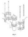
Fig. 1 is a schematic of one embodiment of a liquid treatment system for ultrasonically energizing a liquid and emitting ultraviolet light to the energized liquid;Fig. 2 is a longitudinal (e.g., vertical) cross-section of a housing of the system ofFig. 1 and illustrating an ultrasonic horn and a baffle assembly therein; andFig. 3 is an exploded perspective of the ultrasonic horn and the baffle assembly ofFig. 2 .- Corresponding reference characters indicate corresponding parts throughout the drawings.
- With particular reference now to
Fig. 1 , in one embodiment a liquid treatment system, indicated generally at 10, for treating a flowing liquid is operable to ultrasonically energize a liquid and emit ultraviolet light to the energized liquid as the liquid flows through the system. The term "liquid", as used herein, is intended to refer to a single component liquid, a solution comprised of two or more components in which at least one of the components is a liquid such as a liquid-liquid mixture, a liquid-gas mixture or a liquid in which particulate matter is entrained, or other viscous fluids. In one suitable embodiment, the liquid treated by thetreatment system 10 may be an industrial wastewater having one or more impurities. It is understood, however, that theliquid treatment system 10 can be used to treat other types of liquids including other types of water, such as, potable water, swimming pool water, and process water. Theliquid treatment system 10 disclosed herein may be used by itself or may be a component of a larger liquid treatment process. - In one suitable embodiment, as illustrated in
Fig. 1 , theliquid treatment system 10 comprises an ultrasonic treatment housing (or chamber), indicated generally at 12, defining aninterior space 14 for receiving at least a portion of a waveguide assembly, indicated generally at 16. Thehousing 12 is generally elongate and has an inlet end 18 (a lower end in the orientation of the illustrated embodiment) and an outlet end 20 (an upper end in the orientation of the illustrated embodiment). Thehousing 12 is configured such that wastewater (broadly, a liquid to be treated) enters theinterior space 14 of the housing at theinlet end 18 thereof, flows generally longitudinally within the housing (e.g., upward in the orientation of illustrated embodiment) and exits the housing generally at the outlet end 20 of the housing. More particularly, thehousing 12 has one or more inlet ports 22 (one such inlet port being illustrated inFig. 1 ) formed therein through which wastewater to be treated within the housing is delivered to theinterior space 14 thereof. It will be understood by one skilled in the art that theinlet end 18 of thehousing 12 may include more than one inlet port 22 and remain within the scope of this invention. For example, although not shown, thehousing 12 may comprise two inlet ports, wherein the first inlet port and the second inlet port are suitably in parallel, spaced relationship with each other. Thehousing 12 also has at least oneoutlet port 24 at theoutlet end 20 thereof for allowing wastewater to exit theinterior space 14 of the housing. Thus, wastewater flows into theinterior space 14 of thehousing 12 through the inlet port 22, flows through the interior space, and exists through theoutlet port 24. - In the illustrated embodiment, the
housing 12 is generally cylindrical, thereby having a generally annular cross-section. However, it is contemplated that the cross-section of thehousing 12 may be other than annular, such as polygonal or another suitable shape, and remain within the scope of this disclosure. As described below, at least aportion 26 of thehousing 12 is suitably constructed of a transparent material. In the illustrated embodiment, theportion 26 of thehousing 12 is constructed of quartz glass while the remainder of the housing is constructed of stainless steel. It is understood, however, that thehousing 12 may be constructed from any suitable material as long as the material is compatible with the wastewater being treated in the housing, the pressure at which the housing is intended to be subjected to during operation, and other system conditions such as temperature. - With reference still to
Fig. 1 , thewaveguide assembly 16 extends longitudinally at least in part within theinterior space 14 of thehousing 12 to ultrasonically energize the wastewater (and any other components of the wastewater, e.g., impurities) flowing through the interior space of the housing. In particular, thewaveguide assembly 16 of the illustrated embodiment extends longitudinally from theinlet end 18 of thehousing 12 up into theinterior space 14 thereof to aterminal end 28 of the waveguide assembly, which is disposed intermediate the inlet port 22 and theoutlet port 24. Although illustrated inFig. 1 as extending longitudinally into theinterior space 14 of thehousing 12, it is understood that thewaveguide assembly 16 may extend laterally from asidewall 30 of the housing, running horizontally through the interior space thereof. Typically, thewaveguide assembly 16 is mounted, either directly or indirectly, to thehousing 12 as will be described later herein. - The
waveguide assembly 16 suitably comprises an elongateultrasonic horn 32 disposed within theinterior space 14 of thehousing 12 intermediate the inlet port 22 and theoutlet port 24 for complete submersion within the wastewater being treated in the housing, and more suitably, in the illustrated embodiment, it is aligned coaxially with the housing. Theultrasonic horn 32 has anouter surface 34 that together with aninner surface 36 of thesidewall 30 of thehousing 12 defines aflow path 38 within theinterior space 14 of the housing along which wastewater and other components flow past the ultrasonic horn within the housing (this portion of the flow path being broadly referred to herein as the ultrasonic treatment zone). - The
ultrasonic horn 32 has an upper end defining theterminal end 28 of thewaveguide assembly 16 and a longitudinally oppositelower end 40. It is particularly suitable that thewaveguide assembly 16 also comprises abooster 42 coaxially aligned with and connected at anupper end 44 thereof to thelower end 40 of theultrasonic horn 32. It is understood, however, that thewaveguide assembly 16 may comprise only theultrasonic horn 32 and remain within the scope of this disclosure. It is also contemplated that thebooster 42 may be disposed entirely exterior of thehousing 12, with theultrasonic horn 32 mounted on the housing without departing from the scope of this disclosure. - The
waveguide assembly 16, and more particularly thebooster 42, is suitably mounted on thehousing 12 at theinlet end 18 thereof by a mounting member (not shown) that is configured to vibrationally isolate the waveguide assembly (which vibrates ultrasonically during operation thereof) from the housing. That is, the mounting member inhibits the transfer of longitudinal and transverse mechanical vibration of thewaveguide assembly 16 to thehousing 12 while maintaining the desired transverse position of the waveguide assembly (and in particular the ultrasonic horn 32) within theinterior space 14 of the housing and allowing both longitudinal and transverse displacement of theultrasonic horn 32 within the housing. The mounting member also at least in part (e.g., along with thebooster 42 and/orlower end 40 of the ultrasonic horn 32) closes theinlet end 18 of thehousing 12. Examples of suitable mounting member configurations are illustrated and described inU.S. Patent No. 6,676,003 . - In one suitable embodiment, the mounting member is of single-piece construction. Even more suitably, the mounting member may be formed integrally with the booster 42 (and more broadly with the waveguide assembly 16). However, it is understood that the mounting member may be constructed separately from the
waveguide assembly 16 and remain within the scope of this disclosure. It is also understood that one or more components of the mounting member may be separately constructed and suitably connected or otherwise assembled together. - The mounting member may be further constructed to be generally rigid (e.g., resistant to static displacement under load) so as to hold the
waveguide assembly 16 in proper alignment within theinterior space 14 of thehousing 12. For example, the rigid mounting member in one embodiment may be constructed of a non-elastomeric material, more suitably metal, and even more suitably the same metal from which the booster (and more broadly the waveguide assembly 16) is constructed. The term "rigid" is not, however, intended to mean that the mounting member is incapable of dynamic flexing and/or bending in response to ultrasonic vibration of thewaveguide assembly 16. In other embodiments, the rigid mounting member may be constructed of an elastomeric material that is sufficiently resistant to static displacement under load but is otherwise capable of dynamic flexing and/or bending in response to ultrasonic vibration of thewaveguide assembly 16. - A suitable ultrasonic drive system includes at least an
exciter 46 and apower source 48 disposed exterior of thehousing 12 and operatively connected to thebooster 42 to energize thewaveguide assembly 16 to mechanically vibrate ultrasonically. In one embodiment, the drive system is capable of operating thewaveguide assembly 16 at a frequency in the range of about 15 kHz to about 100 kHz, more suitably in the range of about 15 kHz to about 60 kHz, and even more suitably in the range of about 20 kHz to about 40 kHz. Such ultrasonic drive systems are well known to those skilled in the art and need not be further described herein. Examples of suitable ultrasonic drive systems include a Model 20A3000 system available from Dukane Ultrasonics of St. Charles, Illinois, and a Model 2000CS system available from Herrmann Ultrasonics of Schaumberg, Illinois. - With particular reference to
Fig. 1 , theultrasonic horn 32 has two or more (i.e., a plurality of) agitatingmembers 50, 50' connected to theultrasonic horn 32 and extending at least in part transversely outward from theouter surface 34 of the ultrasonic horn in longitudinally spaced relationship with each other. Five such agitatingmembers 50, 50' can be seen inFig. 1 . Theultrasonic horn 32 is suitably sized to have a length equal to about one-half of the resonating wavelength (otherwise commonly referred to as one-half wavelength) of the ultrasonic horn. It is understood, however, that theultrasonic horn 32 may be sized to have any increment of one-half wavelength without departing from the scope of this disclosure. - In the illustrated embodiment, four of the five agitating
members 50 comprise a series of four washer-shaped rings that extend continuously about the circumference of theultrasonic horn 32 in longitudinally spaced relationship with each other and transversely (e.g., radially in the illustrated embodiment) outward from theouter surface 34 of the ultrasonic horn. In this manner, the vibrational displacement of each of the agitatingmembers 50 relative to theultrasonic horn 32 is relatively uniform about the circumference of the ultrasonic horn. It is understood, however, that the agitatingmembers 50 need not each be continuous about the circumference of theultrasonic horn 32. For example, the agitatingmembers 50 may instead be in the form of spokes, blades, fins or other discrete structural members that extend transversely outward from theouter surface 34 of theultrasonic horn 32. - As illustrated in
Fig. 1 , the other one of the agitating members 50' (i.e., the central agitating member) has a T-shape. Specifically, the agitating member 50' disposed at a nodal region of theultrasonic horn 32, as described more fully below, has a T-shape. It has been found that agitating members 50' having a T-shape, generate a strong radial (e.g., horizontal) acoustic wave that further increases the cavitation effect as described more fully herein. - It is understood that the number of agitating
members 50, 50' (e.g., the four rings and one t-shaped member in the illustrated embodiment) may be less than or more than five without departing from the scope of this disclosure. It is also understood that the longitudinal spacing between the agitatingmembers 50, 50' may be other than as illustrated inFig. 1 and described above (e.g., either closer or spaced further apart). Furthermore, while the agitatingmembers 50, 50' illustrated inFig. 1 are equally longitudinally spaced from each other, it is alternatively contemplated that where more than two agitating members are present the spacing between longitudinally consecutive agitating members need not be uniform to remain within the scope of this disclosure. - The locations of the agitating
members 50, 50' along the length of theultrasonic horn 32 are at least in part a function of the intended vibratory displacement of the agitating members upon vibration of the ultrasonic horn. For example, in the illustrated embodiment ofFig. 1 , theultrasonic horn 32 has a nodal region located generally longitudinally centrally of the ultrasonic horn. As used herein, the "nodal region" of theultrasonic horn 32 refers to a longitudinal region or segment of the ultrasonic horn along which little (or no) longitudinal displacement occurs during ultrasonic vibration of the ultrasonic horn and transverse (e.g., radial in the illustrated embodiment) displacement of the ultrasonic horn is generally maximized. Transverse displacement of theultrasonic horn 32 suitably comprises transverse expansion of the ultrasonic horn but may also include transverse movement (e.g., bending) of the ultrasonic horn. - In the illustrated embodiment of
Fig. 1 , the configuration of the one-half wavelengthultrasonic horn 32 is such that the nodal region is particularly defined by a nodal plane (i.e., a plane transverse to the ultrasonic horn at which no longitudinal displacement occurs while transverse displacement is generally maximized) is present. This plane is also sometimes referred to as a "nodal point". Accordingly, agitating members 50 (e.g., in the illustrated embodiment, the rings) that are disposed longitudinally further from the nodal region of theultrasonic horn 32 will experience primarily longitudinal displacement while the agitating member 50' that are longitudinally nearer to or at the nodal region (e.g., the T-shaped agitating member) will experience an increased amount of transverse displacement and a decreased amount of longitudinal displacement relative to the longitudinally distal agitating members. It is understood that theultrasonic horn 32 may be configured so that the nodal region is other than centrally located longitudinally on the ultrasonic horn member without departing from the scope of this disclosure. It is also understood that one or more of the agitatingmembers 50, 50' may be longitudinally located on the ultrasonic horn so as to experience both longitudinal and transverse displacement relative to theultrasonic horn 32 upon ultrasonic vibration of the ultrasonic horn. - The agitating
members 50, 50' are sufficiently constructed (e.g., in material and/or dimension such as thickness and transverse length, which is the distance that the agitating member extends transversely outward from theouter surface 34 of the ultrasonic horn 32) to facilitate dynamic motion, and in particular dynamic flexing/bending of the agitating members in response to the ultrasonic vibration of the ultrasonic horn. In one particularly suitable embodiment, for a given ultrasonic frequency at which thewaveguide assembly 16 is to be operated in the housing (otherwise referred to herein as the predetermined frequency of the waveguide assembly) and a particular wastewater to be treated within thehousing 12, the agitatingmembers 50, 50' andultrasonic horn 32 are suitably constructed and arranged to operate the agitating members in what is referred to herein as an ultrasonic cavitation mode at the predetermined frequency. - As used herein, the ultrasonic cavitation mode of the agitating
members 50, 50' refers to the vibrational displacement of the agitating members sufficient to result in cavitation of the liquid being treated at the predetermined ultrasonic frequency. For example, where the liquid flowing within thehousing 12 comprises water, and the ultrasonic frequency at which thewaveguide assembly 16 is to be operated (i.e., the predetermined frequency) is about 20 kHZ, one or more of the agitatingmembers 50, 50' are suitably constructed to provide a vibrational displacement of at least 1.75 mils (i.e., 0.00175 inches, or 0.044 mm) to establish a cavitation mode of the agitating members. It is understood that thewaveguide assembly 16 may be configured differently (e.g., in material, size, etc.) to achieve a desired cavitation mode associated with the particular liquid being treated. For example, as the viscosity of the liquid being treated changes, the cavitation mode of the agitating members may need to be changed. - Ultrasonic cavitation refers to the formation, growth and implosive collapse of bubbles in liquid due to ultrasonic energization thereof. Such cavitation results from pre-existing weak points in the liquid, such as gas-filled crevices in suspended particulate matter or transient microbubbles from prior cavitation events. As ultrasound passes through a liquid, the expansion cycles exert negative pressure on the liquid, pulling the molecules away from one another. Where the ultrasonic energy is sufficiently intense, the expansion cycle creates cavities in the liquid when the negative pressure exceeds the local tensile strength of the liquid, which varies according to the type and purity of liquid.
- Small gas bubbles formed by the initial cavities grow upon further absorption of the ultrasonic energy. Under the proper conditions, these bubbles undergo a violent collapse, generating very high pressures and temperatures. In some fields, such as what is known as sonochemistry, chemical reactions take advantage of these high pressures and temperatures brought on by cavitation. In addition, the growth and violent collapse of the bubbles themselves provides a desirably rigorous agitation of the wastewater.
- In particularly suitable embodiments, the cavitation mode of the agitating
members 50, 50' corresponds to a resonant mode of the agitating members whereby vibrational displacement of the agitating members is amplified relative to the displacement of theultrasonic horn 32. However, it is understood that cavitation may occur without the agitatingmembers 50, 50' operating in their resonant mode, or even at a vibrational displacement that is greater than the displacement of theultrasonic horn 32, without departing from the scope of this disclosure. - In general, the
ultrasonic horn 32 may be constructed of a metal having suitable acoustical and mechanical properties. Examples of suitable metals for construction of theultrasonic horn 32 include, without limitation, aluminum, monel, titanium, stainless steel, and some alloy steels. It is also contemplated that all or part of theultrasonic horn 32 may be coated with another metal such as silver, platinum, gold, palladium, lead dioxide, and copper to mention a few. In one particularly suitable embodiment, the agitatingmembers 50, 50' are constructed of the same material as theultrasonic horn 32, and are more suitably formed integrally with the ultrasonic horn. In other embodiments, one or more of the agitatingmembers 50, 50' may instead be formed separate from theultrasonic horn 32 and connected thereto. - While the agitating
members 50, 50' (e.g., the rings) illustrated inFig. 1 are relatively flat, i.e., relatively rectangular in cross-section, it is understood that the rings may have a cross-section that is other than rectangular without departing from the scope of this disclosure. The term "cross-section" is used in this instance to refer to a cross-section taken along one transverse direction (e.g., radially in the illustrated embodiment) relative to the ultrasonic horn'souter surface 34. Additionally, although the agitating members 50 (e.g., the rings) illustrated inFig. 1 are constructed only to have a transverse component, it is contemplated that one or more of the agitating members 50' may have at least one longitudinal (e.g., axial) component to take advantage of transverse vibrational displacement of the ultrasonic horn 32 (e.g., at and near the nodal region of the ultrasonic horn illustrated inFig. 1 ) during ultrasonic vibration of the waveguide assembly 16 (e.g., the T-shaped agitating member). - The
interior space 14 of the housing has aliquid intake zone 52 in which initial swirling of wastewater within theinterior space 14 of thehousing 12 occurs upstream of the agitatingmembers 50, 50' of theultrasonic horn 32. Thisintake zone 52 is particularly useful where thehousing 12 is used for mixing two or more components together (e.g., the wastewater, hydrogen peroxide, and/or ozone in the illustrated embodiment) whereby initial mixing is facilitated by the swirling action in theintake zone 52 as the components to be mixed enter thehousing 12. Additionally, when treating impurities in the wastewater, it may be desirable to add one or more ingredients (e.g., hydrogen peroxide, ozone) that can be premixed with the wastewater being treated before the wastewater comes into contact with the agitatingmembers 50, 50' of theultrasonic horn 32. In one suitable use, for example, the additional ingredient(s) can be used as an oxidizing agent to allow for better removal of the impurities from the wastewater as described in more detail below. - A baffle assembly, generally indicated at 60, is disposed within the
interior space 14 of thehousing 12, and in particular generally transversely adjacent theinner surface 36 of thesidewall 30 of the housing and in generally transversely opposed relationship with theultrasonic horn 32. Thebaffle assembly 60 comprises one ormore baffle members 62 extending at least in part transversely inward from theinner surface 36 of thesidewall 30 of thehousing 12 toward theultrasonic horn 32. More suitably, the one ormore baffle members 62 extend transversely inward from the housing'sinner surface 36 to a position longitudinally intersticed with the agitatingmembers 50, 50' that extend outward from theouter surface 34 of theultrasonic horn 32. The term "longitudinally intersticed" is used herein to mean that a longitudinal line drawn parallel to the longitudinal axis of theultrasonic horn 32 passes through both the agitatingmembers 50, 50' and thebaffle members 62. As one example, in the illustrated embodiment thebaffle assembly 60 comprises four, generally annular baffle members 62 (i.e., extending continuously about the ultrasonic horn 32) longitudinally intersticed with the five agitatingmembers 50, 50'. - It will be appreciated that the
baffle members 62 thus extend into theflow path 38 of wastewater that flows within theinterior space 14 of thehousing 12 past the ultrasonic horn 32 (e.g., within an ultrasonic treatment zone). As such, thebaffle members 62 inhibit wastewater against flowing along theinner surface 36 of the housing'ssidewall 30 past theultrasonic horn 32, and more suitably the baffle members facilitate the flow of wastewater transversely inward toward the ultrasonic horn for flowing over the agitatingmembers 50, 50' of the ultrasonic horn to thereby facilitate ultrasonic energization (i.e., agitation) of the wastewater. - It is contemplated that the
baffle members 62 need not be annular or otherwise extend continuously about the ultrasonic horn. For example, thebaffle members 62 may extend discontinuously about theultrasonic horn 32, such as in the form of spokes, bumps, segments or other discrete structural formations that extend transversely inward from adjacent theinner surface 36 of thesidewall 30 of thehousing 12. The term "continuously" in reference to thebaffle members 62 extending continuously about theultrasonic horn 32 does not exclude a baffle members as being two or more arcuate segments arranged in end-to-end abutting relationship, i.e., as long as no significant gap is formed between such segments. Suitable baffle member configurations are disclosed inU.S. Patent No. 7,703,698 . - While the
baffle members 62 illustrated inFigs. 1-3 are each generally flat, e.g., having a generally thin rectangular cross-section, it is contemplated that one or more of the baffle members may each be other than generally flat or rectangular in cross-section to further facilitate the flow of gas bubbles within theinterior space 14 of thehousing 12. The term "cross-section" is used in this instance to refer to a cross-section taken along one transverse direction (e.g., radially in the illustrated embodiment, relative to the ultrasonic horn's outer surface 34). - As illustrated in
Fig. 1 , theliquid treatment system 10 further comprises an ultravioletlight source 66 for emitting ultraviolet light to irradiate the wastewater (i.e., the liquid) received in theinterior space 14 of thehousing 12 as it flows from the inlet port 22 to theoutlet port 24. In one suitable embodiment, theultraviolet light source 66 is positioned for emitting ultraviolet light substantially throughout the entireinterior space 14 of thehousing 12. For example, theultraviolet light source 66 may have a length L1 that is substantially equal to the length L2 of thehousing 12 and is positioned for emitting ultraviolet light into theinterior space 14 along the length of the housing. In another configuration and as illustrated inFig. 1 , one ormore reflectors 68 may be disposed relative to theinterior space 14 of thehousing 12 to deflect ultraviolet light emitted by theultraviolet light source 66 throughout the length of the interior space of the housing. In this configuration, the length L1 of the ultravioletlight source 66 can be substantially less than the length L2 of thehousing 12. - As seen in
Fig. 1 , theultraviolet light source 66 is suitably disposed exterior of thehousing 12 and is positioned adjacent thetransparent portion 26 thereof (i.e., the portion of the housing constructed of quartz glass). Thetransparent portion 26 of thehousing 12 is thus sized and shaped for allowing substantially all of the ultraviolet light emitted by theultraviolet light source 66 into theinterior space 14 of thehousing 12. It is understood that thetransparent portion 26 may comprise only a portion of thehousing 12 or that it may comprise the entire housing and remain within the scope of this disclosure. - As illustrated in
Fig. 1 , theultraviolet light source 66 is positioned to emit ultraviolet light into theinterior space 14 of thehousing 12 toward the outlet end 20 thereof and just beyond theterminal end 28 of theultrasonic horn 32. Wastewater passing through theinterior space 14 of thehousing 12 adjacent theultraviolet light source 66 is first highly energized (e.g., at least agitated and more suitably subjected to cavitation) by theultrasonic horn 32. While the ultraviolet is deflected or otherwise irradiated throughout theinterior space 14 of thehousing 12, the most intense region of ultraviolet light is generally adjacent the outlet end 20 of the housing. It is contemplated that a baffling system (not shown) can be disposed within theinterior space 14 of thehousing 12 adjacent the outlet end 20 thereof to provide a torturous flow path for the wastewater thereby increasing the dwell time during which the wastewater is subjected to ultraviolet light. - In one suitable embodiment, the
ultraviolet light source 66 is operable to emit ultraviolet light at a wavelength in the range of about 172 nanometers and about 600 nanometers. More suitably, e.g., thelight source 66 is operable to emit light at a wavelength in the range of about 172 nanometers to about 300 nanometers where the liquid to be treated is relatively colorless or near colorless. In another suitable embodiment, theultraviolet light source 66 is operable to emit ultraviolet light at a wavelength in the range of about 300 nanometers to about 600 nanometers for liquids having color (e.g., waste streams having dye therein) and highly viscous liquids or semi-liquids (e.g., sludge). The ultravioletlight source 66 is operatively connected to a suitablepower supply unit 70 for supplying sufficient electrical power to the ultraviolet light source to generate and emit ultraviolet light into theinterior space 14 of thehousing 12. - In the illustrated embodiment, the
liquid treatment system 10 more particularly comprises an oxidizing agent source for delivering an oxidizing agent into theinterior space 14 of thehousing 12. In one suitable embodiment, e.g., hydrogen peroxide and ozone are each delivered into theinterior space 14 of thehousing 12. The hydrogen peroxide is delivered using asuitable pump 72, which draws hydrogen peroxide from asupply container 74 and delivers the hydrogen peroxide through a hydrogenperoxide inlet port 76 into theinterior space 14 of thehousing 12. Hydrogen peroxide (H2O2) decomposes to hydroxyl radicals (·OH), as shown below. The hydroxyl radical is an aggressive oxidant that reacts with organics.
H2O2 → 2(·OH) - An
ozone generator 80 is provided in theliquid treatment system 10 to generate ozone for delivery into theinterior space 14 of thehousing 12 through anozone inlet port 82. Ozone (O3) decomposes in water to form a superoxide radical ion (O2-), which is a strong oxidizing agent, and a hydroperoxide radical (O2H). The hydroperoxide radical further decomposes to form another superoxide radical ion (O2-) and a hydrogen ion (H+).
O3 + OH- → O2 + O2H
O2H ↔ O2- + H+ - It is contemplated that either one of the hydrogen peroxide and the ozone may be used by itself in the
liquid treatment system 10 within the scope of this disclosure. It is also contemplated that other oxidation agents may be used or that, in some embodiments, the oxidation agents may be omitted altogether. - The
inlet end 18 of thehousing 12 is in fluid communication with a suitable delivery system that is operable to direct the wastewater into, and more suitably through, theinterior space 14 of thehousing 12 from acontinuous source 86. In one suitable embodiment, the delivery system comprises one or more pumps 88 (one pump being illustrated inFig. 1 ) operable to pump the wastewater from thecontinuous source 86 thereof to theinlet end 18 of thehousing 12 via suitable conduits (not shown). It is understood that the delivery system may be configured to deliver wastewater from more than onesource 86, such as when mixing wastewaters, to the housing without departing from the scope of this disclosure. It is also contemplated that delivery systems other than that illustrated inFig. 1 and described herein may be used to deliver wastewater to theinlet end 18 of thehousing 12 without departing from the scope of this disclosure. - In one suitable embodiment, the
liquid treatment system 10 is suitable for use in a continuous flow process wherein wastewater continuously flows through the system. For example, in one specific application, as noted above, wastewater is treated to kill, remove, and/or oxidize microorganisms prior to being disposed. Theliquid treatment system 10 of the present disclosure may accomplish this through emitting ultraviolet light to the wastewater while the wastewater is cavitated, which is caused by theultrasonic horn 32. As mentioned above, sparging of ozone gas into the housing and/or the addition of hydrogen peroxide can also be used. It is contemplated, though, that theliquid treatment system 10 may be used in a liquid treatment system in which wastewater is treated in accordance with a batch process instead of a continuous flow process and remain within the scope of this disclosure. - In operation according to one embodiment of the
liquid treatment system 10 of the present disclosure, the liquid treatment system is used to treat microorganisms in a wastewater. Specifically, the wastewater is delivered (e.g., by thepump 88 described above) via conduits to one or more inlet ports 22 formed in thehousing 12. Ozone and hydrogen peroxide are delivered in thehousing 12 to mix with the wastewater. As the wastewater enters theinterior space 14 of thehousing 12 via the inlet port 22, the orientation of the inlet port can induce a relatively swirling action thereby mixing the ozone, hydrogen peroxide, and wastewater together to form a wastewater solution. - The wastewater solution flows upward within the
interior space 14 of thehousing 12 and past thewaveguide assembly 16, and more particularly theultrasonic horn 32. Theultrasonic horn 32 is driven by the drive system to vibrate at a predetermined ultrasonic frequency. In response to ultrasonic excitation of theultrasonic horn 32, the agitatingmembers 50, 50' that extend outward from theouter surface 34 of the ultrasonic horn dynamically flex/bend relative to the ultrasonic horn, or displace transversely (depending on the longitudinal position of the agitating member relative to the nodal region of the ultrasonic horn). - The wastewater flows longitudinally upward along the
flow path 38 between theouter surface 34 of theultrasonic horn 32 and theinner surface 36 of the housing'ssidewall 30 so that the ultrasonic vibration and the dynamic motion of the agitatingmembers 50, 50' agitate the wastewater and more suitably cause cavitation in the wastewater. Thebaffle members 62 of thebaffle assembly 60 disrupt the longitudinal flow of the wastewater along theinner surface 36 of the housing'ssidewall 30 and repeatedly direct the flow transversely inward to flow over the vibrating agitating members. As mentioned above, theultrasonic horn 32 causes the cavitation in the wastewater solution which expedites the desired oxidation reactions. The sonochemistry caused by theultrasonic horn 32 accelerates and enhances the decomposition of the hydrogen peroxide and ozone to form the above-described radicals, which are used to treat impurities in the wastewater. The wastewater solution, while it is cavitated (i.e., energized), flows past theultraviolet light source 66. The ultravioletlight source 66 irradiates the wastewater for further treatment. - The use of ultraviolet light in this
system 10 increases the efficiency and the efficacy of the degradation of the impurities in the wastewater. First, the ultraviolet light photochemically cleaves some of the ozone and peroxide agents to produce higher concentrations of the superoxide and radicals which work in conjunction with the sonochemistry to break down the impurities in the wastewater. Secondly, the nature of the high energy ultraviolet light starts the breakdown of the impurities by their absorption of the radiation followed by scission of the chemical bonds. For example, with respect to dyes and other colored agents, the sonochemistry will further breakdown these compound fragments, due to these intermediates being chemically unstable and therefore it is easier for them to undergo further degradation in the ultrasonic system. - An ultraviolet lamp of the ultraviolet
light source 66 can be adjusted to produce either a broad ultraviolet light emission or specific narrower wavelength range by careful selection of the lamp bulb. For example, Fusion UV Systems, Inc. of Gaithersburg, Maryland offers a series of ultraviolet lamp bulbs with the following emission ranges: - H-bulb 210-315 nanometers
- D-bulb 350-450 nanometers
- V-bulb 400-450 nanometers
- M-bulb 365 nanometers and 406 nanometers.
- The
liquid treatment system 10 may also optionally be combined with a post-processing system in fluid communication with the outlet end 20 of the housing for processing the wastewater after the wastewater exits the housing. For example, the illustratedliquid treatment system 10 may be combined with one or more pressure gauges to monitor the pressure in thehousing 12. One ormore filter units 90 may also be disposed along the flow path of the wastewater downstream of thehousing 12 to filter out particulate material, such as dirt, debris or other contaminates that may be present in the wastewater. For example, in the one embodiment, a first filter unit may be constructed to filter out particles sized greater than about 0.5 microns and a second filter unit downstream from the first filter unit is constructed to further filter out particles sized greater than about 0.2 microns. It is understood, however, that only one, or more than two filter units may be used, or that the filter units may be omitted altogether. - The post-processing system may further comprise a degassing and
bubble removal unit 92 that is operable to remove gas bubbles from the wastewater after passing through thehousing 12. In one suitable embodiment, the degassing andbubble removal unit 92 comprises a conventional membrane contactor. The construction and operation of membrane contactors is well known to those skilled in the art and is therefore not described in further detail herein. One example of a suitable membrane contactor is that available from Membrana of Charlotte, North Carolina, U.S.A. under the trade name SuperPhobic. One or more sensor units may also be provided to monitor various characteristics of the wastewater such as, without limitation, pH, conductivity, viscosity, temperature, color, surface tension and other characteristics. - In one embodiment, such as when hydrogen peroxide is introduced into the
housing 12 to be used as an oxidizing agent for removing impurities from the wastewater, the residual hydrogen peroxide may need to be removed from the exit stream by a post processing unit that reacts with the hydrogen peroxide. For example, this post processing unit may include a platinum or silver surface that decomposes any residual hydrogen peroxide. Similarly, when ozone is introduced to aid in the removal of impurities, a post processing unit, such as a destruct unit, may be used to decompose any ozone exiting the housing. - Following treatment in the
housing 12 or, if used, post-processing, the treated wastewater may be directed to a storage container, reused, or discharged to a suitable location. - When introducing elements of the present invention or preferred embodiments thereof, the articles "a", "an", "the", and "said" are intended to mean that there are one or more of the elements. The terms "comprising", "including", and "having" are intended to be inclusive and mean that there may be additional elements other than the listed elements.
- As various changes could be made in the above constructions and methods without departing from the scope of the invention, it is intended that all matter contained in the above description and shown in the accompanying drawings shall be interpreted as illustrative and not in a limiting sense.
Claims (12)
- A liquid treatment system (10) comprising:an ultrasonic waveguide assembly (16) having an ultrasonic horn (32) operable at an ultrasonic frequency to ultrasonically energize liquid;an ultraviolet light source (66) for emitting ultraviolet light onto the liquid while the liquid is ultrasonically energized by the ultrasonic horn (32); anda housing (12) defining an interior space (14) for receiving the liquid, at least a portion of the ultrasonic horn (32) being located within the interior space (14) of the housing (12) for ultrasonically energizing the liquid within the housing (12);wherein the ultrasonic horn (32) has an outer surface (34) and a plurality of discrete agitating members (50) extending outward from the outer surface (34), the agitating members (50) being constructed and arranged for dynamic motion of the agitating members (50) relative to the ultrasonic horn (32) upon ultrasonic vibration of the ultrasonic horn (32);the liquid treatment system (10) further comprising a baffle assembly (60) disposed within the interior space (14) of the housing (12), and transversely adjacent an inner surface (36) of a sidewall (30) of the housing (12) and in transversely opposed relationship with the ultrasonic horn (32).
- The liquid treatment system (10) set forth in claim 1, wherein
the housing (12) has at least one inlet port (22) for receiving liquid into the interior space (14) of the housing (12) and at least one outlet port (24) for allowing liquid to exit the interior space (14) of the housing (12), the outlet port (24) being spaced from the inlet port (22) so that liquid flows through the interior space (14) of the housing (12) from the inlet port (22) to the outlet port (24);
wherein the ultrasonic waveguide assembly (16) is disposed within the interior space (14) of the housing (12), the ultrasonic horn (32) is disposed at least in part intermediate the inlet port (22) and the outlet port (24) of the housing (12) and is operable at an ultrasonic frequency to ultrasonically energize liquid flowing from the inlet port (22) to the outlet port (24) within the housing (12). - The liquid treatment system (10) set forth in claim 1 or 2 wherein the ultraviolet light source (66) is capable of emitting ultraviolet light at a wavelength in the range of about 172 nanometers to about 600 nanometers.
- The liquid treatment system (10) set forth in claim 1 or 2 wherein at least a portion (26) of the housing (12) comprises a transparent material for allowing ultraviolet light to irradiate through the housing (12) into the interior space (14) thereof to treat liquid in the interior space (14) of the housing (12).
- The liquid treatment system (10) set forth in claim 4 wherein the ultraviolet light source (66) is disposed exterior of the housing (12) and adjacent the transparent portion (26) of the housing (12).
- The liquid treatment system (10) set forth in claim 2 wherein the housing (12) has a length L2, the ultraviolet light source (66) being capable of emitting ultraviolet light along the length of the housing (12).
- The liquid treatment system (10) set forth in claim 2 further comprising at least one reflector (68) for redirecting the ultraviolet light emitted by the ultraviolet light source (66) within the interior space (14) of the housing (12).
- The liquid treatment system (10) set forth in claim 1 or 2 further comprising an oxidizing agent source for introducing an oxidizing agent into the liquid.
- The liquid treatment system (10) set forth in claim 8 wherein the oxidizing agent source comprises a pump (72) for pumping the oxidizing agent into the interior space (14) of the housing (12).
- The liquid treatment system (10) set forth in claim 2 further comprising an oxidizing agent source for introducing an oxidizing agent into the liquid wherein the oxidizing agent source comprises a pump for pumping the oxidizing agent into the interior space (14) of the housing (12) and wherein the oxidizing agent source comprises a first pump for pumping a first oxidizing agent into the interior space (14) of the housing (12), and a second pump for pumping a second oxidizing agent into the interior space (14) of the housing (12), the first oxidizing agent being different than the second oxidizing agent.
- The liquid treatment system (10) set forth in claim 2 further comprising an oxidizing agent source for introducing an oxidizing agent into the liquid wherein the oxidizing agent comprises at least one of hydrogen peroxide and ozone.
- The liquid treatment system (10) set forth in claim 2 further comprising an oxidizing agent source for introducing an oxidizing agent into the liquid wherein the oxidizing agent source comprises an ozone generator (80) and the oxidizing agent comprises ozone.
Applications Claiming Priority (2)
| Application Number | Priority Date | Filing Date | Title |
|---|---|---|---|
| US11/963,139US8858892B2 (en) | 2007-12-21 | 2007-12-21 | Liquid treatment system |
| PCT/IB2008/055394WO2009083874A2 (en) | 2007-12-21 | 2008-12-17 | Liquid treatment system |
Publications (3)
| Publication Number | Publication Date |
|---|---|
| EP2222606A2 EP2222606A2 (en) | 2010-09-01 |
| EP2222606A4 EP2222606A4 (en) | 2012-03-28 |
| EP2222606B1true EP2222606B1 (en) | 2015-08-12 |
Family
ID=40788878
Family Applications (1)
| Application Number | Title | Priority Date | Filing Date |
|---|---|---|---|
| EP08868425.3AActiveEP2222606B1 (en) | 2007-12-21 | 2008-12-17 | Liquid treatment system |
Country Status (6)
| Country | Link |
|---|---|
| US (1) | US8858892B2 (en) |
| EP (1) | EP2222606B1 (en) |
| KR (1) | KR20100107450A (en) |
| CN (1) | CN101952207B (en) |
| BR (1) | BRPI0819582B8 (en) |
| WO (1) | WO2009083874A2 (en) |
Families Citing this family (28)
| Publication number | Priority date | Publication date | Assignee | Title |
|---|---|---|---|---|
| US7703698B2 (en) | 2006-09-08 | 2010-04-27 | Kimberly-Clark Worldwide, Inc. | Ultrasonic liquid treatment chamber and continuous flow mixing system |
| US7810743B2 (en) | 2006-01-23 | 2010-10-12 | Kimberly-Clark Worldwide, Inc. | Ultrasonic liquid delivery device |
| US9283188B2 (en) | 2006-09-08 | 2016-03-15 | Kimberly-Clark Worldwide, Inc. | Delivery systems for delivering functional compounds to substrates and processes of using the same |
| US8034286B2 (en) | 2006-09-08 | 2011-10-11 | Kimberly-Clark Worldwide, Inc. | Ultrasonic treatment system for separating compounds from aqueous effluent |
| US7998322B2 (en) | 2007-07-12 | 2011-08-16 | Kimberly-Clark Worldwide, Inc. | Ultrasonic treatment chamber having electrode properties |
| US7947184B2 (en) | 2007-07-12 | 2011-05-24 | Kimberly-Clark Worldwide, Inc. | Treatment chamber for separating compounds from aqueous effluent |
| US8454889B2 (en)* | 2007-12-21 | 2013-06-04 | Kimberly-Clark Worldwide, Inc. | Gas treatment system |
| US8858892B2 (en) | 2007-12-21 | 2014-10-14 | Kimberly-Clark Worldwide, Inc. | Liquid treatment system |
| US8632613B2 (en) | 2007-12-27 | 2014-01-21 | Kimberly-Clark Worldwide, Inc. | Process for applying one or more treatment agents to a textile web |
| US9421504B2 (en) | 2007-12-28 | 2016-08-23 | Kimberly-Clark Worldwide, Inc. | Ultrasonic treatment chamber for preparing emulsions |
| US20090166177A1 (en) | 2007-12-28 | 2009-07-02 | Kimberly-Clark Worldwide, Inc. | Ultrasonic treatment chamber for preparing emulsions |
| US8057573B2 (en) | 2007-12-28 | 2011-11-15 | Kimberly-Clark Worldwide, Inc. | Ultrasonic treatment chamber for increasing the shelf life of formulations |
| US8215822B2 (en)* | 2007-12-28 | 2012-07-10 | Kimberly-Clark Worldwide, Inc. | Ultrasonic treatment chamber for preparing antimicrobial formulations |
| US8206024B2 (en)* | 2007-12-28 | 2012-06-26 | Kimberly-Clark Worldwide, Inc. | Ultrasonic treatment chamber for particle dispersion into formulations |
| US8685178B2 (en) | 2008-12-15 | 2014-04-01 | Kimberly-Clark Worldwide, Inc. | Methods of preparing metal-modified silica nanoparticles |
| US8163388B2 (en) | 2008-12-15 | 2012-04-24 | Kimberly-Clark Worldwide, Inc. | Compositions comprising metal-modified silica nanoparticles |
| IT1404748B1 (en)* | 2011-02-10 | 2013-11-29 | Ecotec Srl | METHOD FOR DECONTAMINATING, WITH THE USE OF ULTRASOUNDS, ENVIRONMENTAL, CIVIL AND INDUSTRIAL WATERS. |
| CN102583639A (en)* | 2012-02-10 | 2012-07-18 | 上海交通大学 | Water treatment device and method reinforcing photocatalysis mass transfer |
| GB2500664A (en)* | 2012-03-29 | 2013-10-02 | Quantock Associates Ltd | Liquid purification using ultrasound and electromagnetic radiation |
| WO2013155283A1 (en)* | 2012-04-11 | 2013-10-17 | Arana Holdings, Llc | Reactor for water treatment and method thereof |
| DE102012018996A1 (en)* | 2012-09-27 | 2014-03-27 | Klaus Büttner | Process for treating ballast water and apparatus for treating ballast water |
| CN103008287B (en)* | 2012-12-21 | 2015-12-09 | 江苏安华电气自动化有限公司 | A kind of multi-function washing machine |
| PL3393978T3 (en) | 2015-12-23 | 2023-10-09 | Novolabs Limited | Liquid treatment method and apparatus |
| GB2553600B (en)* | 2016-12-23 | 2019-10-16 | Pulcea Ltd | Ectoparasite Reduction |
| CN107364998B (en)* | 2017-08-07 | 2020-10-27 | 苏州久沛环保科技有限公司 | Treatment process of medium-concentration organic industrial wastewater |
| CN110314244A (en)* | 2019-07-08 | 2019-10-11 | 界首永恩机电科技有限公司 | A kind of sterilized method of coolant liquid |
| CN111871349B (en)* | 2020-07-24 | 2021-11-16 | 湖北省农业科学院农产品加工与核农技术研究所 | Pretreatment decalcification method for preparing peptide from fish scales |
| CN115155483B (en)* | 2022-07-08 | 2023-07-14 | 山东蓝湾新材料有限公司 | Photoinitiated ultrasonic stirring polymerization reactor and application method thereof |
Family Cites Families (323)
| Publication number | Priority date | Publication date | Assignee | Title |
|---|---|---|---|---|
| US2115056A (en) | 1934-06-19 | 1938-04-26 | Colloid Corp | Apparatus for producing suspensions |
| US2307206A (en) | 1940-03-14 | 1943-01-05 | Armour & Co | Spraying device |
| DE970926C (en) | 1948-02-05 | 1958-11-13 | Mueller Hans | Device for mixing, stirring, etc. of liquids |
| US2620894A (en) | 1948-03-25 | 1952-12-09 | American Viscose Corp | Deaeration of viscous and plastic materials |
| US2661192A (en) | 1949-08-11 | 1953-12-01 | Sonic Res Corp | Means for treating materials with intense alternating shear forces |
| US2584053A (en)* | 1949-11-28 | 1952-01-29 | Sonic Res Corp | Means for the application of alternating shear at sonic frequencies to the treatmentof material |
| GB774043A (en)* | 1954-05-05 | 1957-05-01 | Bendix Aviat Corp | Sonic transducer with mechanical motion transformer |
| US3066232A (en) | 1959-06-12 | 1962-11-27 | Branson Instr | Ultrasonic transducer |
| US3338992A (en)* | 1959-12-15 | 1967-08-29 | Du Pont | Process for forming non-woven filamentary structures from fiber-forming synthetic organic polymers |
| DE1181160B (en)* | 1961-07-29 | 1964-11-12 | Bayer Ag | Process for the production of finely divided dyes or pigments |
| US3160138A (en) | 1961-09-26 | 1964-12-08 | Ultrasonic Ind Inc | High intensity sound generator |
| US3502763A (en)* | 1962-02-03 | 1970-03-24 | Freudenberg Carl Kg | Process of producing non-woven fabric fleece |
| US3239998A (en) | 1962-05-02 | 1966-03-15 | Eastman Kodak Co | Ultrasonic degassing of multiple emulsions in a vertical unit |
| US3278165A (en) | 1963-02-25 | 1966-10-11 | Sonic Eng Corp | Method and apparatus for generating acoustic vibrations in flowing fluids |
| US3246881A (en)* | 1963-07-16 | 1966-04-19 | Branson Instr | Process and apparatus for treating heat sensitive material with sonic vibrations |
| US3284991A (en) | 1963-12-19 | 1966-11-15 | Dow Chemical Co | Ultrasonic degassing of liquids |
| US3275787A (en)* | 1963-12-30 | 1966-09-27 | Gen Electric | Process and apparatus for producing particles by electron melting and ultrasonic agitation |
| US3273631A (en)* | 1964-01-13 | 1966-09-20 | Neuman Entpr Ltd | Ultrasonic fluid heating, vaporizing, cleaning and separating apparatus |
| US3325348A (en)* | 1964-09-24 | 1967-06-13 | Fitchburg Paper | Ultrasonic device for placing materials in suspension |
| US3202281A (en)* | 1964-10-01 | 1965-08-24 | Weston David | Method for the flotation of finely divided minerals |
| US3326470A (en) | 1965-04-27 | 1967-06-20 | Babcock & Wilcox Co | Liquid atomizer |
| US3490584A (en)* | 1965-08-31 | 1970-01-20 | Cavitron Corp | Method and apparatus for high frequency screening of materials |
| US3425951A (en) | 1966-03-21 | 1969-02-04 | Fuji Photo Film Co Ltd | Defoaming apparatus |
| US3341394A (en)* | 1966-12-21 | 1967-09-12 | Du Pont | Sheets of randomly distributed continuous filaments |
| US3463321A (en) | 1967-02-24 | 1969-08-26 | Eastman Kodak Co | Ultrasonic in-line filter system |
| US3542615A (en) | 1967-06-16 | 1970-11-24 | Monsanto Co | Process for producing a nylon non-woven fabric |
| US3479873A (en) | 1967-11-13 | 1969-11-25 | Fischer & Porter Co | Self-cleaning electrodes |
| US3542345A (en) | 1968-06-13 | 1970-11-24 | Ultrasonic Systems | Ultrasonic vials and method and apparatus for mixing materials in same |
| US3519251A (en)* | 1968-07-11 | 1970-07-07 | Frederick G Hammitt | Vibratory unit with baffle |
| US3567185A (en)* | 1968-10-03 | 1971-03-02 | Shell Oil Co | Fluid resonator system |
| US3591946A (en) | 1968-11-26 | 1971-07-13 | Loe Ind | Fluid-degassing system |
| DE2048006B2 (en)* | 1969-10-01 | 1980-10-30 | Asahi Kasei Kogyo K.K., Osaka (Japan) | Method and device for producing a wide nonwoven web |
| DE1950669C3 (en)* | 1969-10-08 | 1982-05-13 | Metallgesellschaft Ag, 6000 Frankfurt | Process for the manufacture of nonwovens |
| US3664191A (en) | 1970-06-01 | 1972-05-23 | Fischer & Porter Co | Explosion-proof self-cleaning electrodes |
| GB1371781A (en) | 1970-09-22 | 1974-10-30 | Sandoz Ltd | Finishing process |
| GB1404575A (en) | 1971-07-27 | 1975-09-03 | Kodak Ltd | Method of dispersing a pigment in a resin |
| US3782547A (en)* | 1971-10-12 | 1974-01-01 | Harry Dietert Co | Structure for ultrasonic screening |
| US4062768A (en) | 1972-11-14 | 1977-12-13 | Locker Industries Limited | Sieving of materials |
| US3904392A (en) | 1973-03-16 | 1975-09-09 | Eastman Kodak Co | Method of and apparatus for debubbling liquids |
| US3873071A (en) | 1973-08-01 | 1975-03-25 | Tatebe Seishudo Kk | Ultrasonic wave cleaning apparatus |
| US3865350A (en)* | 1974-01-14 | 1975-02-11 | Wilson A Burtis | Liquid homogenizing device |
| BE823966A (en) | 1974-01-29 | 1975-04-16 | PROCEDURE FOR EXECUTING REACTIONS BETWEEN PULVERULENT SUBSTANCES AND GASEOUS SUBSTANCES | |
| US4266879A (en)* | 1975-01-16 | 1981-05-12 | Mcfall Richard T | Fluid resonator |
| US4168295A (en) | 1975-11-20 | 1979-09-18 | Vernon D. Beehler | Apparatus for enhancing chemical reactions |
| US4070167A (en) | 1976-03-08 | 1978-01-24 | Eastman Kodak Company | Sonic apparatus for removing gas from photographic emulsion |
| US4122797A (en) | 1976-03-25 | 1978-10-31 | Kurashiki Boseki Kabushiki Kaisha | Ultrasonic sound source and method for manufacturing rectangular diaphragm of ultrasonic sound source |
| US4218221A (en) | 1978-01-30 | 1980-08-19 | Cottell Eric Charles | Production of fuels |
| JPS5628221Y2 (en) | 1978-03-11 | 1981-07-04 | ||
| US4259021A (en)* | 1978-04-19 | 1981-03-31 | Paul R. Goudy, Jr. | Fluid mixing apparatus and method |
| CH657067A5 (en) | 1979-11-08 | 1986-08-15 | Cottell Eric Charles | Process for separating suspended solids and agglomerated other solids in suspending and bonding liquids respectively |
| US4249986A (en) | 1980-02-12 | 1981-02-10 | Branson Ultrasonics Corporation | High frequency horn with soft metallic coating |
| JPS5834051Y2 (en) | 1980-02-20 | 1983-07-30 | 岐阜プラスチック工業株式会社 | insulation lid |
| US4340563A (en)* | 1980-05-05 | 1982-07-20 | Kimberly-Clark Corporation | Method for forming nonwoven webs |
| US4372296A (en)* | 1980-11-26 | 1983-02-08 | Fahim Mostafa S | Treatment of acne and skin disorders and compositions therefor |
| JPS6223889Y2 (en) | 1981-01-14 | 1987-06-18 | ||
| US4425718A (en) | 1981-04-30 | 1984-01-17 | The Ichikin, Ltd. | Apparatus for development and fixation of dyes with a printed textile sheet by application of microwave emanation |
| US4556467A (en) | 1981-06-22 | 1985-12-03 | Mineral Separation Corporation | Apparatus for ultrasonic processing of materials |
| US4398925A (en) | 1982-01-21 | 1983-08-16 | The United States Of America As Represented By The Administrator Of The National Aeronautics And Space Administration | Acoustic bubble removal method |
| US4511254A (en)* | 1982-12-06 | 1985-04-16 | Henry North | Cavitators |
| JPS59156405A (en) | 1983-02-28 | 1984-09-05 | Konishiroku Photo Ind Co Ltd | Ultrasonic defoaming method and apparatus therefor |
| DE3325195A1 (en) | 1983-07-13 | 1985-01-24 | Uwe Prof.Dr. Faust | METHOD FOR TEMPERATURE A LIQUID |
| US4743361A (en)* | 1983-10-31 | 1988-05-10 | Internationale Octrooi Maatschappij "Octropa" Bv | Manipulation of particles |
| US4612016A (en) | 1984-03-08 | 1986-09-16 | Ciba-Geigy Corporation | Process for dyeing cellulosic textile materials |
| GB8417240D0 (en)* | 1984-07-06 | 1984-08-08 | Unilever Plc | Particle separation |
| DE3535922C2 (en)* | 1984-10-09 | 1999-01-14 | Mitsubishi Chem Corp | Process for cleaning soot using an ultrasonic vibration screening device |
| DE3438798C2 (en) | 1984-10-23 | 1987-01-02 | Löffler, Friedrich, Prof. Dr.-Ing., 7500 Karlsruhe | Method and device for measuring the solid concentration and the grain size distribution in a suspension by means of ultrasound |
| DE3505001C1 (en) | 1985-02-14 | 1986-04-17 | Merck Patent Gmbh, 6100 Darmstadt | Process for degassing liquid crystalline materials |
| JPS61259781A (en) | 1985-05-13 | 1986-11-18 | Toa Nenryo Kogyo Kk | Vibrator for ultrasonic pulverization having curved multistage edge part |
| JPS621413A (en) | 1985-06-27 | 1987-01-07 | Ishido Group:Kk | Degassing method and apparatus therefor |
| US4663220A (en)* | 1985-07-30 | 1987-05-05 | Kimberly-Clark Corporation | Polyolefin-containing extrudable compositions and methods for their formation into elastomeric products including microfibers |
| JPH0341791Y2 (en) | 1985-08-29 | 1991-09-02 | ||
| US4983045A (en)* | 1985-11-22 | 1991-01-08 | Reica Corporation | Mixer |
| GB8612759D0 (en)* | 1986-05-27 | 1986-07-02 | Unilever Plc | Manipulating particulate matter |
| IT1195845B (en) | 1986-11-21 | 1988-10-27 | Ultraviolet Technology Italia | METHOD AND DEVICE FOR STERILIZATION OF FLUIDS |
| JPH0455248Y2 (en) | 1986-12-25 | 1992-12-25 | ||
| AT389235B (en) | 1987-05-19 | 1989-11-10 | Stuckart Wolfgang | METHOD FOR CLEANING LIQUIDS BY MEANS OF ULTRASOUND AND DEVICES FOR CARRYING OUT THIS METHOD |
| US4848159A (en)* | 1987-05-22 | 1989-07-18 | The Boeing Company | Ultrasonic inspection probe for laminated structures |
| GB8718756D0 (en) | 1987-08-07 | 1987-09-16 | Unilever Plc | Supporting means |
| GB8724067D0 (en)* | 1987-10-14 | 1987-11-18 | Unilever Plc | Manipulating particles |
| US4974780A (en) | 1988-06-22 | 1990-12-04 | Toa Nenryo Kogyo K.K. | Ultrasonic fuel injection nozzle |
| US4929279A (en)* | 1989-02-21 | 1990-05-29 | Basf Corporation | Process for dispersing organic pigments with ultrasonic radiation |
| US5059249A (en)* | 1989-02-21 | 1991-10-22 | Basf Corp. | Process for dispersing organic pigments with ultrasonic radiation |
| JPH02281185A (en) | 1989-04-21 | 1990-11-16 | Yasuyuki Sugano | Ultrasonic acceleration of room temperature nuclear fusion |
| JPH0353195A (en) | 1989-07-21 | 1991-03-07 | Matsushita Electric Ind Co Ltd | energy generator |
| US5026167A (en)* | 1989-10-19 | 1991-06-25 | Heat Systems Incorporated | Ultrasonic fluid processing system |
| US5032027A (en)* | 1989-10-19 | 1991-07-16 | Heat Systems Incorporated | Ultrasonic fluid processing method |
| JPH03157129A (en) | 1989-11-16 | 1991-07-05 | Mita Ind Co Ltd | Disperser |
| US5096532A (en) | 1990-01-10 | 1992-03-17 | Kimberly-Clark Corporation | Ultrasonic rotary horn |
| DE4106998C2 (en)* | 1990-03-07 | 1997-08-14 | Reica Corp | Mixing device |
| EP0459967A3 (en) | 1990-05-17 | 1992-04-08 | Monsanto Company | Pigmented dispersion and its use in colored thermoplastic resin sheet |
| US5087320A (en) | 1990-05-18 | 1992-02-11 | Kimberly-Clark Corporation | Ultrasonic rotary horn having improved end configuration |
| US5110403A (en) | 1990-05-18 | 1992-05-05 | Kimberly-Clark Corporation | High efficiency ultrasonic rotary horn |
| CA2041018C (en) | 1990-05-18 | 2000-07-18 | Joseph G. Neuwirth | Ultrasonic rotary horn |
| US5122165A (en) | 1990-07-10 | 1992-06-16 | International Environmental Systems, Inc. | Removal of volatile compounds and surfactants from liquid |
| JPH0486367A (en) | 1990-07-30 | 1992-03-18 | Aisin Seiki Co Ltd | Fuel injection valve |
| DE9017338U1 (en) | 1990-12-20 | 1991-03-07 | Bandelin electronic GmbH & Co KG, 12207 Berlin | Flow vessel for a disintegrator |
| GB9105980D0 (en)* | 1991-03-21 | 1991-05-08 | Tioxide Group Services Ltd | Method for preparing pigments |
| DE4109625A1 (en) | 1991-03-23 | 1992-09-24 | Krautkraemer Gmbh | ULTRASONIC MEASUREMENT METHOD FOR THE WALL THICKNESS DEVELOPMENT OF A WELDED SEAM OF A PIPE |
| US20010040935A1 (en) | 1991-06-11 | 2001-11-15 | Case Leslie Catron | Commercial power production by catalytic fusion of deuterium gas |
| US5335449A (en)* | 1991-08-15 | 1994-08-09 | Net/Tech International, Inc. | Delivery system for an agriculturally active chemical |
| US5330100A (en)* | 1992-01-27 | 1994-07-19 | Igor Malinowski | Ultrasonic fuel injector |
| FR2686805A1 (en) | 1992-02-04 | 1993-08-06 | Kodak Pathe | DEVICE FOR DISSOLVING GASEOUS BUBBLES CONTAINED IN A LIQUID COMPOSITION USED IN PARTICULAR FOR PHOTOGRAPHIC PRODUCTS. |
| US5269297A (en) | 1992-02-27 | 1993-12-14 | Angiosonics Inc. | Ultrasonic transmission apparatus |
| GB9213198D0 (en) | 1992-06-22 | 1992-08-05 | Univ Cardiff | Phase partition separation method |
| US5258413A (en) | 1992-06-22 | 1993-11-02 | The University Of Akron | Continuous ultrasonic devulcanization of valcanized elastomers |
| US5466722A (en) | 1992-08-21 | 1995-11-14 | Stoffer; James O. | Ultrasonic polymerization process |
| US5519670A (en) | 1992-08-25 | 1996-05-21 | Industrial Sound Technologies, Inc. | Water hammer driven cavitation chamber |
| US5375926A (en) | 1992-09-14 | 1994-12-27 | Nihon Techno Kabushiki Kaisha | Apparatus for mixing and dispensing fluid by flutter of vibrating vanes |
| US5665383A (en) | 1993-02-22 | 1997-09-09 | Vivorx Pharmaceuticals, Inc. | Methods for the preparation of immunostimulating agents for in vivo delivery |
| GB9304545D0 (en) | 1993-03-05 | 1993-04-21 | Univ London | Method and apparatus for positional manipulation of suspended particles |
| WO1994026390A1 (en) | 1993-05-11 | 1994-11-24 | Carlson, David, V. | Multilayered piezoelectric resonator for the separation of suspended particles |
| FR2705333B1 (en) | 1993-05-18 | 1995-08-04 | Omnium Traitement Valorisa | Process and installation for the purification of an aqueous effluent by oxidation on an adsorbent support. |
| US5372634A (en) | 1993-06-01 | 1994-12-13 | The United States Of America As Represented By The Secretary Of The Navy | Sonic apparatus for degassing liquids |
| DE69429692T2 (en) | 1993-07-06 | 2002-08-29 | Tuboscope Vetco International Inc., Houston | Ultrasonic test method for pipes and pipe strings and associated sensor device |
| GB2285142B (en) | 1993-10-16 | 1997-12-17 | Rawson Francis F H | Fluid processing |
| CA2175065A1 (en) | 1993-10-26 | 1995-05-04 | Linda S. Kramer | A process for activating a metal surface for conversion coating |
| US5326164A (en)* | 1993-10-28 | 1994-07-05 | Logan James R | Fluid mixing device |
| US6169045B1 (en)* | 1993-11-16 | 2001-01-02 | Kimberly-Clark Worldwide, Inc. | Nonwoven filter media |
| JP3077879B2 (en)* | 1994-02-15 | 2000-08-21 | インターナショナル・ビジネス・マシーンズ・コーポレ−ション | Apparatus and method for applying microwave energy to a web-type quantified processing material |
| US6010592A (en) | 1994-06-23 | 2000-01-04 | Kimberly-Clark Corporation | Method and apparatus for increasing the flow rate of a liquid through an orifice |
| US6020277A (en) | 1994-06-23 | 2000-02-01 | Kimberly-Clark Corporation | Polymeric strands with enhanced tensile strength, nonwoven webs including such strands, and methods for making same |
| US6380264B1 (en)* | 1994-06-23 | 2002-04-30 | Kimberly-Clark Corporation | Apparatus and method for emulsifying a pressurized multi-component liquid |
| JP2741344B2 (en) | 1994-07-22 | 1998-04-15 | 大同メタル工業株式会社 | Ultrasonic processing equipment |
| DE4433744C2 (en) | 1994-09-21 | 2001-02-22 | Schueler Rolf | Device for mixing media to produce liquid systems |
| ES2181800T3 (en)* | 1994-10-31 | 2003-03-01 | Kimberly Clark Co | HEAVY DENSITY FILTER MEDIA, HIGH DENSITY. |
| FR2727118B1 (en) | 1994-11-18 | 1997-01-03 | Rhone Poulenc Chimie | FUNCTIONALIZED POLYORGANOSILOXANES AND ONE OF THEIR PREPARATION METHODS |
| DE4444525A1 (en) | 1994-11-30 | 1996-06-05 | Hielscher Gmbh | Ultrasonic liquid vaporiser using sonotrode |
| SE504204C2 (en) | 1994-12-28 | 1996-12-09 | Rune Soeremark | Method and apparatus for treating fluids and using this fluid |
| US6361697B1 (en)* | 1995-01-10 | 2002-03-26 | William S. Coury | Decontamination reactor system and method of using same |
| US5681457A (en) | 1995-10-10 | 1997-10-28 | Mahoney; Robert F. | Electrodynamic fluid treatment system |
| US5803270A (en) | 1995-10-31 | 1998-09-08 | Institute Of Paper Science & Technology, Inc. | Methods and apparatus for acoustic fiber fractionation |
| JP3487699B2 (en)* | 1995-11-08 | 2004-01-19 | 株式会社日立製作所 | Ultrasonic treatment method and apparatus |
| KR100445769B1 (en)* | 1995-11-30 | 2004-10-15 | 킴벌리-클라크 월드와이드, 인크. | Superfine Microfiber Nonwoven Web |
| GB9524950D0 (en) | 1995-12-06 | 1996-02-07 | Kodak Ltd | Debubbling apparatus |
| US5868153A (en) | 1995-12-21 | 1999-02-09 | Kimberly-Clark Worldwide, Inc. | Ultrasonic liquid flow control apparatus and method |
| ZA969680B (en) | 1995-12-21 | 1997-06-12 | Kimberly Clark Co | Ultrasonic liquid fuel injection on apparatus and method |
| US6053424A (en) | 1995-12-21 | 2000-04-25 | Kimberly-Clark Worldwide, Inc. | Apparatus and method for ultrasonically producing a spray of liquid |
| US5721180A (en)* | 1995-12-22 | 1998-02-24 | Pike; Richard Daniel | Laminate filter media |
| JP2700058B2 (en) | 1996-01-23 | 1998-01-19 | 工業技術院長 | Non-contact micromanipulation method using ultrasonic waves |
| US5770124A (en) | 1996-04-30 | 1998-06-23 | Minnesota Mining And Manufacturing Company | Method of making glittering cube-corner retroreflective sheeting |
| US6218483B1 (en)* | 1996-05-06 | 2001-04-17 | Rohm And Haas Company | Powder coating of epoxy resin, imidazole-epoxy resin catalyst or polyamine, polyamine powder and amine scavenger |
| DE19618217A1 (en) | 1996-05-07 | 1997-11-13 | Rainer Dr Ing Imhof | Electrochemical treatment has vibrating electrodes |
| JP2001502225A (en) | 1996-05-10 | 2001-02-20 | ビーティージー・インターナショナル・リミテッド | Apparatus and method for ultrasonically manipulating particles in a liquid medium |
| US6221258B1 (en)* | 1996-06-14 | 2001-04-24 | Case Western Reserve University | Method and apparatus for acoustically driven media filtration |
| US7211928B2 (en) | 1996-08-05 | 2007-05-01 | Puskas William L | Apparatus, circuitry, signals and methods for cleaning and/or processing with sound |
| US7336019B1 (en) | 2005-07-01 | 2008-02-26 | Puskas William L | Apparatus, circuitry, signals, probes and methods for cleaning and/or processing with sound |
| JPH1060331A (en) | 1996-08-13 | 1998-03-03 | Kao Corp | Method for producing ink for inkjet recording |
| CN1303985C (en) | 1996-08-22 | 2007-03-14 | Rtp药品公司 | Compositions comprising microparticles of water-insoluble substances and method for preparing same |
| JPH10120716A (en)* | 1996-08-27 | 1998-05-12 | Mitsui Chem Inc | Preliminary polymerized solid catalyst, its preparation and heterogeneous polymerization system of olefin |
| US6055859A (en)* | 1996-10-01 | 2000-05-02 | Agency Of Industrial Science And Technology | Non-contact micromanipulation method and apparatus |
| ES2116930B1 (en)* | 1996-10-04 | 1999-04-01 | Consejo Superior Investigacion | PROCEDURE AND DEVICE FOR CONTINUOUS ULTRASONIC WASHING OF TEXTILES. |
| GB9621832D0 (en) | 1996-10-19 | 1996-12-11 | Univ Cardiff | Removing partiles from suspension |
| EP0839585A3 (en) | 1996-10-31 | 2000-12-27 | Eastman Kodak Company | Method and apparatus for testing transducer horn assembly debubbling devices |
| US5964926A (en)* | 1996-12-06 | 1999-10-12 | Kimberly-Clark Worldwide, Inc. | Gas born particulate filter and method of making |
| WO1998044058A1 (en) | 1997-03-27 | 1998-10-08 | E.I. Du Pont De Nemours And Company | High intensity ultrasonic milling in the preparation of ink jet inks |
| GB9708984D0 (en) | 1997-05-03 | 1997-06-25 | Univ Cardiff | Particle manipulation |
| US5937906A (en) | 1997-05-06 | 1999-08-17 | Kozyuk; Oleg V. | Method and apparatus for conducting sonochemical reactions and processes using hydrodynamic cavitation |
| EP0885641B1 (en) | 1997-06-17 | 2003-01-29 | Konica Corporation | Method and device for debubbling a liquid using ultrasonic waves |
| JP3450672B2 (en) | 1997-10-29 | 2003-09-29 | キヤノン株式会社 | Method for producing toner for developing electrostatic image and toner for developing electrostatic image |
| US6074466A (en)* | 1997-10-31 | 2000-06-13 | Seiren Co., Ltd. | Method of manufacturing water base disperse ink for ink-jet recording |
| US5916203A (en)* | 1997-11-03 | 1999-06-29 | Kimberly-Clark Worldwide, Inc. | Composite material with elasticized portions and a method of making the same |
| US6312790B1 (en)* | 1997-12-18 | 2001-11-06 | Ppg Industries Ohio, Inc. | Methods and apparatus for depositing pyrolytic coatings having a fade zone over a substrate and articles produced thereby |
| US6113559A (en) | 1997-12-29 | 2000-09-05 | Klopotek; Peter J. | Method and apparatus for therapeutic treatment of skin with ultrasound |
| US6376444B1 (en)* | 1998-02-20 | 2002-04-23 | Procter & Gamble Company | Garment stain removal product which uses sonic or ultrasonic waves |
| AU8131498A (en) | 1998-02-25 | 1999-09-15 | Eliseo Alfredo Bonilla Leanos | Device for the treatment of liquids by mechanical vibration |
| US6617588B1 (en)* | 1998-04-08 | 2003-09-09 | Idaho State University | Photosonolysis for decomposition of toxics in water |
| JPH11326154A (en)* | 1998-04-30 | 1999-11-26 | L'air Liquide | Formation of fluid flow containing size-controlled particles |
| AUPP427398A0 (en)* | 1998-06-23 | 1998-07-16 | Novapharm Research (Australia) Pty Ltd | Improved disinfection |
| JP2000024494A (en) | 1998-07-13 | 2000-01-25 | Toto Ltd | Ultrasonic treating device |
| GB2339703B (en) | 1998-07-22 | 2002-05-01 | Univ Cardiff | Particle manipulation device |
| US6383301B1 (en)* | 1998-08-04 | 2002-05-07 | E. I. Du Pont De Nemours And Company | Treatment of deagglomerated particles with plasma-activated species |
| DE19842005C2 (en) | 1998-09-04 | 2000-09-28 | Fraunhofer Ges Forschung | Method and device for treating biological waste |
| DE19854013C2 (en) | 1998-11-12 | 2002-07-11 | Hielscher Gmbh | Ultrasonic horn |
| DE29825063U1 (en) | 1998-11-12 | 2004-06-24 | Dr. Hielscher Gmbh | Monolithic ultrasonic sonotrode has half-wave segments, each with plate-shaped ring near vibration maximum; ultrasonic power is radiated on both sides via ring segment surfaces |
| US6482327B1 (en) | 1998-11-20 | 2002-11-19 | Proudo Co., Ltd. | Liquid treating process and apparatus, as well as liquid treating system |
| JP2990273B1 (en) | 1998-11-20 | 1999-12-13 | 工業技術院長 | Ultrasonic non-contact micromanipulation method and apparatus using multiple sound sources |
| CO5150202A1 (en)* | 1998-12-31 | 2002-04-29 | Kimberly Clark Co | COMPOSITION OF FACIAL TISSU AND METHOD FOR USE FOR THE SECRETARY OF SKIN IRRITANTS OF THE NASAL SECRETION |
| WO2000041794A1 (en) | 1999-01-15 | 2000-07-20 | University College Cardiff Consultants Ltd. | Particle manipulation |
| NZ513408A (en) | 1999-03-15 | 2002-11-26 | Daishin Design Corp | Method and apparatus for treatment of organic matter-containing wastewater |
| DE19913397A1 (en) | 1999-03-25 | 2000-09-28 | Marc Breitbach | Regeneration of loaded adsorbents used widely throughout industry, in liquid-flushed fluidized bed, is enhanced by subjecting them to ultrasound for outstanding rates of heat and mass transfer, reaching all particles |
| US6200486B1 (en) | 1999-04-02 | 2001-03-13 | Dynaflow, Inc. | Fluid jet cavitation method and system for efficient decontamination of liquids |
| JP3854006B2 (en) | 1999-05-07 | 2006-12-06 | 日本テクノ株式会社 | Vibrating fluid agitator |
| FR2793811B1 (en) | 1999-05-17 | 2002-01-11 | R V X | CEMENTING PROCESS, REACTOR FOR CARRYING OUT SAID METHOD AND INSTALLATION COMPRISING SUCH A REACTOR |
| US6811813B1 (en) | 1999-05-19 | 2004-11-02 | Sarnoff Corporation | Method of coating micrometer sized inorganic particles |
| US6368414B1 (en) | 1999-06-17 | 2002-04-09 | Walter Johnson | Washing parts with ultrasonic energy |
| JP2001017970A (en) | 1999-07-08 | 2001-01-23 | Kubota Corp | Water treatment equipment using a submerged membrane filtration device |
| GB9916851D0 (en) | 1999-07-20 | 1999-09-22 | Univ Wales Bangor | Manipulation of particles in liquid media |
| DE19938254B4 (en) | 1999-08-12 | 2004-05-19 | Dr. Hielscher Gmbh | Process for regenerating adsorbents |
| DE10009326A1 (en)* | 2000-02-28 | 2001-08-30 | Rs Kavitationstechnik | Mixing device used for mixing emulsion or suspension comprises housing and flow through chamber whose cross-section is larger in flow direction of material stream which flows through it |
| JP4012357B2 (en) | 2000-03-13 | 2007-11-21 | 株式会社日本触媒 | Powder classification method |
| DE10015144A1 (en) | 2000-03-29 | 2001-10-04 | Henry Bergmann | Electrochemical reaction accompanied preferably by ultrasonic vibration, for use in disinfection of any liquid system, employs conductor as vibration inducer and electrochemical electrode |
| US6506584B1 (en)* | 2000-04-28 | 2003-01-14 | Battelle Memorial Institute | Apparatus and method for ultrasonic treatment of a liquid |
| US6605252B2 (en) | 2000-05-02 | 2003-08-12 | Japan Techno Co., Ltd. | Vibrationally stirring apparatus for sterilization, sterilizing apparatus and sterilizing method |
| US6481645B1 (en) | 2000-05-22 | 2002-11-19 | Shurflo Pump Mfg. Company, Inc. | Condiment dispensing nozzle apparatus and method |
| US6582611B1 (en)* | 2000-07-06 | 2003-06-24 | William B. Kerfoot | Groundwater and subsurface remediation |
| US6817541B2 (en) | 2000-09-01 | 2004-11-16 | Del Industries, Inc. | Ozone systems and methods for agricultural applications |
| EP1184089A1 (en)* | 2000-09-04 | 2002-03-06 | Telsonic Ag | Apparatus and process for sifting, sorting, screening, filtering or sizing substances |
| CA2421916C (en) | 2000-09-13 | 2008-11-18 | Anthony Francis Collings | Process for treating a solid-liquid mixture |
| US6593436B2 (en)* | 2000-11-29 | 2003-07-15 | Crompton Corporation | Continuous manufacture of silicone copolymers via static mixing plug flow reactors |
| KR20040020869A (en) | 2000-12-18 | 2004-03-09 | 이 아이 듀폰 디 네모아 앤드 캄파니 | Method and apparatus for ultrasonic sizing of particles in suspensions |
| US6547935B2 (en) | 2001-01-06 | 2003-04-15 | Harold W. Scott | Method and apparatus for treating fluids |
| US6803587B2 (en)* | 2001-01-11 | 2004-10-12 | Waterhealth International, Inc. | UV water disinfector |
| SE522801C2 (en)* | 2001-03-09 | 2004-03-09 | Erysave Ab | Apparatus for separating suspended particles from an ultrasonic fluid and method for such separation |
| US6610314B2 (en) | 2001-03-12 | 2003-08-26 | Kimberly-Clark Worldwide, Inc. | Antimicrobial formulations |
| US6467350B1 (en)* | 2001-03-15 | 2002-10-22 | The Regents Of The University Of California | Cylindrical acoustic levitator/concentrator |
| KR20020073778A (en) | 2001-03-16 | 2002-09-28 | 주경 | Mix disintegration apparatus of super fines powder using ultrasonic wave |
| JP2002355551A (en) | 2001-03-28 | 2002-12-10 | Fuji Electric Co Ltd | Method and apparatus for decomposing environmental pollutants |
| US6770248B2 (en) | 2001-05-04 | 2004-08-03 | Her Majesty The Queen In Right Of Canada, As Represented By The Minister Of National Defence Of Her Majesty's Canadian Government | Flowthrough device for the ultrasonic destruction of microorganisms in fluids |
| AUPR512801A0 (en) | 2001-05-18 | 2001-06-14 | Australian National University, The | Method for the destruction of oocysts |
| US20030051989A1 (en) | 2001-06-18 | 2003-03-20 | Petronetics, Llc. | Method to liberate hydrocarbon fractions from hydrocarbon mixtures |
| US20030042174A1 (en) | 2001-06-18 | 2003-03-06 | Petronetiics Llc. | Method to treat emulsified hydrocarbon mixtures |
| US6911153B2 (en)* | 2001-06-22 | 2005-06-28 | The Halliday Foundation, Inc. | Method and apparatus for treating fluid mixtures with ultrasonic energy |
| JP4269318B2 (en) | 2001-06-25 | 2009-05-27 | 日本テクノ株式会社 | Vibration agitator, treatment apparatus and treatment method using the same |
| US7422695B2 (en) | 2003-09-05 | 2008-09-09 | Foret Plasma Labs, Llc | Treatment of fluids with wave energy from a carbon arc |
| IL144638A (en) | 2001-07-30 | 2005-12-18 | Nano Size Ltd | High power ultrasound reactor for the production of nano-powder materials |
| US6669103B2 (en) | 2001-08-30 | 2003-12-30 | Shirley Cheng Tsai | Multiple horn atomizer with high frequency capability |
| US20030048692A1 (en) | 2001-09-07 | 2003-03-13 | Bernard Cohen | Apparatus for mixing, atomizing, and applying liquid coatings |
| US6576042B2 (en) | 2001-09-11 | 2003-06-10 | Eastman Kodak Company | Process control method to increase deaeration capacity in an ECR by constant voltage operation |
| DE60217146T2 (en) | 2001-09-19 | 2007-10-04 | Adiga, Kayyani C. | METHOD AND DEVICE FOR PRODUCING, EXTRACTION AND DELIVERING MIST WITH ULTRA-FINE PUB |
| JP2003103152A (en) | 2001-09-28 | 2003-04-08 | Fuji Photo Film Co Ltd | Method and device for mixing liquid or solution |
| US6620226B2 (en) | 2001-10-02 | 2003-09-16 | Eastman Kodak Company | Bubble elimination tube with acutely angled transducer horn assembly |
| US6889528B2 (en) | 2001-10-22 | 2005-05-10 | Council Of Scientific & Industrial Research | Process of making rare earth doped optical fiber |
| FR2832703B1 (en) | 2001-11-29 | 2005-01-14 | Electricite De France | SONOELECTROCHEMICAL DEVICE AND SONOELECTROCHEMICAL METHOD FOR DEGRADING ORGANIC MOLECULES |
| US6547903B1 (en) | 2001-12-18 | 2003-04-15 | Kimberly-Clark Worldwide, Inc. | Rotary ultrasonic bonder or processor capable of high speed intermittent processing |
| US6676003B2 (en)* | 2001-12-18 | 2004-01-13 | Kimberly-Clark Worldwide, Inc. | Rigid isolation of rotary ultrasonic horn |
| US6648943B2 (en) | 2001-12-21 | 2003-11-18 | Eastman Kodak Company | Integrated use of deaeration methods to reduce bubbles and liquid waste |
| US7414009B2 (en) | 2001-12-21 | 2008-08-19 | Showa Denko K.K. | Highly active photocatalyst particles, method of production therefor, and use thereof |
| JP4012062B2 (en) | 2002-01-22 | 2007-11-21 | 耕平 青柳 | Methods for cleaning and sterilizing used medical devices |
| JP2005520138A (en)* | 2002-03-12 | 2005-07-07 | ゼネラル フュージョン インコーポレーテッド | Method for inducing fusion and nuclear fusion reactor |
| CN1628155A (en) | 2002-03-14 | 2005-06-15 | 日铁矿业株式会社 | Coated power, coating compsn, and coated article |
| US7118852B2 (en) | 2002-04-11 | 2006-10-10 | Throwleigh Technologies, L.L.C. | Methods and apparatus for decontaminating fluids |
| US6749666B2 (en) | 2002-04-26 | 2004-06-15 | Board Of Regents, The University Of Texas System | Modulated acoustic aggiomeration system and method |
| US7976855B2 (en) | 2002-04-30 | 2011-07-12 | Kimberly-Clark Worldwide, Inc. | Metal ion modified high surface area materials for odor removal and control |
| IL149932A0 (en) | 2002-05-30 | 2002-11-10 | Nano Size Ltd | High power ultrasonic reactor and process for ultrasonic treatment of a reaction material |
| WO2003102737A2 (en) | 2002-06-04 | 2003-12-11 | Protasis Corporation | Method and device for ultrasonically manipulating particles within a fluid |
| US6818128B2 (en) | 2002-06-20 | 2004-11-16 | The Halliday Foundation, Inc. | Apparatus for directing ultrasonic energy |
| JP2004020176A (en) | 2002-06-20 | 2004-01-22 | Masao Umemoto | Ultrasonic heating method |
| US20030234173A1 (en) | 2002-06-20 | 2003-12-25 | Minter Bruce E. | Method and apparatus for treating fluid mixtures with ultrasonic energy |
| US7160516B2 (en)* | 2002-07-30 | 2007-01-09 | Sonics & Materials, Inc. | High volume ultrasonic flow cell |
| DE10243837A1 (en) | 2002-09-13 | 2004-03-25 | Dr. Hielscher Gmbh | Process for continuously processing flowable compositions in a flow cell comprises indirectly sonicating the composition in the flow cell via a liquid placed under elevated pressure |
| US7090391B2 (en) | 2002-09-25 | 2006-08-15 | Reika Kogyo Kabushiki Kaisha | Apparatus and method for mixing by agitation in a multichambered mixing apparatus including a pre-agitation mixing chamber |
| GB0222421D0 (en) | 2002-09-27 | 2002-11-06 | Ratcliff Henry K | Advanced ultrasonic processor |
| US7108137B2 (en)* | 2002-10-02 | 2006-09-19 | Wisconsin Alumni Research Foundation | Method and apparatus for separating particles by size |
| US7004282B2 (en) | 2002-10-28 | 2006-02-28 | Misonix, Incorporated | Ultrasonic horn |
| EP1556544A2 (en)* | 2002-11-01 | 2005-07-27 | International Paper Company | Method of making a stratified paper |
| US6841921B2 (en) | 2002-11-04 | 2005-01-11 | Kimberly-Clark Worldwide, Inc. | Ultrasonic horn assembly stack component connector |
| US6878288B2 (en) | 2002-12-17 | 2005-04-12 | Harold W. Scott | System and apparatus for removing dissolved and suspended solids from a fluid stream |
| US7666410B2 (en)* | 2002-12-20 | 2010-02-23 | Kimberly-Clark Worldwide, Inc. | Delivery system for functional compounds |
| US20040138410A1 (en) | 2003-01-14 | 2004-07-15 | The University Of Akron | Ultrasound assisted process for increasing the crystallinity of slow crystallizable polymers |
| JP2004256783A (en) | 2003-02-24 | 2004-09-16 | Tatsufumi Nishikawa | Surface decoration paint with molecular chain shortened by ultrasonic wave |
| US6770600B1 (en)* | 2003-02-28 | 2004-08-03 | Rohm And Haas Company | Delivery systems for cyclopropene compounds |
| US7018546B2 (en) | 2003-03-06 | 2006-03-28 | Hitachi, Ltd. | Water treatment method and water treatment device |
| US20050155779A1 (en) | 2003-04-08 | 2005-07-21 | Xingwu Wang | Coated substrate assembly |
| US20050025797A1 (en)* | 2003-04-08 | 2005-02-03 | Xingwu Wang | Medical device with low magnetic susceptibility |
| US6897628B2 (en) | 2003-05-16 | 2005-05-24 | Sulphco, Inc. | High-power ultrasound generator and use in chemical reactions |
| DE102004025048A1 (en)* | 2003-05-20 | 2004-12-23 | Futaba Corp., Mobara | Ultra-dispersed carbon primary nanoparticles, e.g. of fullerene, graphite or diamond, useful e.g. as abrasives or lubricants, obtained from agglomerates or agglutinates by wet-milling and/or wet dispersion |
| US20040251566A1 (en) | 2003-06-13 | 2004-12-16 | Kozyuk Oleg V. | Device and method for generating microbubbles in a liquid using hydrodynamic cavitation |
| US7261823B2 (en) | 2003-06-27 | 2007-08-28 | Ultra Technology Europe Ab | Ultrasonic transducer system |
| FR2856609B1 (en) | 2003-06-27 | 2006-12-15 | Geolog Spa | SYSTEM FOR DEGASSING A LIQUID MEDIUM AND ANALYZING GASES CONTAINED IN THE LIQUID ENVIRONMENT |
| KR100530851B1 (en) | 2003-07-29 | 2005-11-24 | 주식회사두합크린텍 | Apparatus for air cleaning and method for air cleaning |
| US20050102009A1 (en) | 2003-07-31 | 2005-05-12 | Peter Costantino | Ultrasound treatment and imaging system |
| WO2005014489A1 (en) | 2003-08-08 | 2005-02-17 | Buettner Klaus | Method for disinfecting liquids |
| US20050042129A1 (en) | 2003-08-22 | 2005-02-24 | Bijan Kazem | Method and apparatus for irradiating fluids |
| US7141518B2 (en) | 2003-10-16 | 2006-11-28 | Kimberly-Clark Worldwide, Inc. | Durable charged particle coatings and materials |
| US7438875B2 (en) | 2003-10-16 | 2008-10-21 | Kimberly-Clark Worldwide, Inc. | Method for reducing odor using metal-modified silica particles |
| US7678367B2 (en)* | 2003-10-16 | 2010-03-16 | Kimberly-Clark Worldwide, Inc. | Method for reducing odor using metal-modified particles |
| JP4456845B2 (en) | 2003-10-17 | 2010-04-28 | 岩谷瓦斯株式会社 | Classification device |
| WO2005042412A1 (en) | 2003-10-29 | 2005-05-12 | University Of Miami | Metal mediated aeration for water and wastewater purification |
| US7331702B2 (en) | 2003-10-31 | 2008-02-19 | Reika Kogyo Kabushiki Kaisha | Agitation mixer |
| US7083322B2 (en) | 2003-12-01 | 2006-08-01 | The Boeing Company | Coating production systems and methods with ultrasonic dispersion and active cooling |
| JP4482322B2 (en) | 2003-12-18 | 2010-06-16 | 浜松ホトニクス株式会社 | Fine particle production method and production apparatus |
| CN1247628C (en) | 2003-12-31 | 2006-03-29 | 中国化工建设总公司常州涂料化工研究院 | Composite nano material modified emulsion and its preparation method |
| JP4728586B2 (en) | 2004-03-16 | 2011-07-20 | Necインフロンティア株式会社 | IP phone method |
| US20050220665A1 (en) | 2004-04-05 | 2005-10-06 | Ding Lambert L | Low temperature sterilization and disinfections method and apparatus for medical apparatus and instruments |
| US20060088138A1 (en) | 2004-04-07 | 2006-04-27 | Andre Jouanneau | Method and apparatus for the generation and the utilization of plasma solid |
| US20050235740A1 (en)* | 2004-04-27 | 2005-10-27 | Guido Desie | Method to improve the quality of dispersion formulations |
| DE102004025836B3 (en) | 2004-05-24 | 2005-12-22 | Dr. Hielscher Gmbh | Method and device for introducing ultrasound into a flowable medium |
| US20060000034A1 (en)* | 2004-06-30 | 2006-01-05 | Mcgrath Kevin P | Textile ink composition |
| DE102004040233B4 (en) | 2004-08-13 | 2006-06-01 | Dr. Hielscher Gmbh | Preparation of algae bio product, useful e.g. as nutrient; and in medicine, comprises preparing algal suspension, providing algal suspension on discharge cell and subjecting the algal suspension on a discharge cell in a narrow column |
| DE102004048230A1 (en) | 2004-10-04 | 2006-04-06 | Institut für Neue Materialien Gemeinnützige GmbH | Process for the preparation of nanoparticles with customized surface chemistry and corresponding colloids |
| US7156201B2 (en)* | 2004-11-04 | 2007-01-02 | Advanced Ultrasonic Solutions, Inc. | Ultrasonic rod waveguide-radiator |
| JP2006187756A (en)* | 2004-12-07 | 2006-07-20 | Reika Kogyo Kk | Stirring and mixing device |
| US7497990B2 (en) | 2004-12-30 | 2009-03-03 | Kimberly-Clark Worldwide Inc. | Process for the destruction of microorganisms on a product |
| CN101128555B (en) | 2005-01-07 | 2013-04-03 | 太尔公司 | Engineered non-polymeric organic particles for chemical mechanical planarization |
| EP1836339B1 (en) | 2005-01-14 | 2010-03-17 | Sonotronic Nagel GmbH | Device and method for applying a liquid medium to a material web |
| US7510321B2 (en) | 2005-02-28 | 2009-03-31 | Impulse Devices, Inc. | Hydraulic actuated cavitation chamber |
| DE202005009923U1 (en) | 2005-04-10 | 2005-09-22 | Riggers, Wolfgang | Device used for reduction of germs in transparent fluid, working with ultra violet light and ultrasound |
| DE102005025118B4 (en) | 2005-05-27 | 2007-05-24 | Igv Institut Für Getreideverarbeitung Gmbh | Cleaning method and apparatus for detachment of microorganisms, mosses and lower plants |
| CN1872710A (en)* | 2005-06-02 | 2006-12-06 | 上海万森水处理有限公司 | Sterilizing unit of ultraviolet radiation for water body cleaned by ultrasonic |
| DE102005034629B4 (en) | 2005-07-19 | 2007-09-13 | Dr. Hielscher Gmbh | Device and method for the mechanical disruption of cells |
| DE102005057333B4 (en)* | 2005-11-28 | 2008-11-20 | Dr. Hielscher Gmbh | Methods and apparatus for sonicating liquids with low frequency power ultrasound |
| US8033173B2 (en) | 2005-12-12 | 2011-10-11 | Kimberly-Clark Worldwide, Inc. | Amplifying ultrasonic waveguides |
| US8191732B2 (en) | 2006-01-23 | 2012-06-05 | Kimberly-Clark Worldwide, Inc. | Ultrasonic waveguide pump and method of pumping liquid |
| US7810743B2 (en) | 2006-01-23 | 2010-10-12 | Kimberly-Clark Worldwide, Inc. | Ultrasonic liquid delivery device |
| US7735751B2 (en)* | 2006-01-23 | 2010-06-15 | Kimberly-Clark Worldwide, Inc. | Ultrasonic liquid delivery device |
| US7424883B2 (en) | 2006-01-23 | 2008-09-16 | Kimberly-Clark Worldwide, Inc. | Ultrasonic fuel injector |
| US7703698B2 (en) | 2006-09-08 | 2010-04-27 | Kimberly-Clark Worldwide, Inc. | Ultrasonic liquid treatment chamber and continuous flow mixing system |
| CZ301067B6 (en) | 2006-02-24 | 2009-10-29 | Ústav makromolekulární chemie AV CR | Iron oxide-based superparamagnetic nanoparticles with modified surface, process of their preparation and use |
| DE102006010010A1 (en)* | 2006-03-04 | 2007-09-06 | Intelligendt Systems & Services Gmbh & Co Kg | Method for ultrasonic testing of a workpiece in a curved area of its surface and suitable test arrangement for carrying out the method |
| KR101088335B1 (en) | 2006-03-24 | 2011-11-30 | 로레알 | Dyeing composition containing thiol / disulfide naphthylimide fluorescent dye, and method for whitening keratin materials using the dye |
| US7372044B2 (en)* | 2006-05-17 | 2008-05-13 | Andrew Ross | UV sterilization of user interface fomites |
| US8034286B2 (en)* | 2006-09-08 | 2011-10-11 | Kimberly-Clark Worldwide, Inc. | Ultrasonic treatment system for separating compounds from aqueous effluent |
| US9283188B2 (en)* | 2006-09-08 | 2016-03-15 | Kimberly-Clark Worldwide, Inc. | Delivery systems for delivering functional compounds to substrates and processes of using the same |
| US20080069887A1 (en) | 2006-09-15 | 2008-03-20 | 3M Innovative Properties Company | Method for nanoparticle surface modification |
| CN101153138A (en) | 2006-09-25 | 2008-04-02 | 天津市振东涂料有限公司 | Method of producing ultra-bright light catalysis degradation antimicrobial environment protection paint |
| US7673516B2 (en) | 2006-12-28 | 2010-03-09 | Kimberly-Clark Worldwide, Inc. | Ultrasonic liquid treatment system |
| US7712353B2 (en) | 2006-12-28 | 2010-05-11 | Kimberly-Clark Worldwide, Inc. | Ultrasonic liquid treatment system |
| US7568251B2 (en)* | 2006-12-28 | 2009-08-04 | Kimberly-Clark Worldwide, Inc. | Process for dyeing a textile web |
| CN101622319B (en) | 2007-01-03 | 2013-05-08 | 内诺格雷姆公司 | Silicon/germanium based nanoparticle inks, doped particles, printing and methods for semiconductor applications |
| US8651230B2 (en) | 2007-07-03 | 2014-02-18 | Industrial Sonomechanics, Llc | High capacity ultrasonic reactor system |
| US7785674B2 (en) | 2007-07-12 | 2010-08-31 | Kimberly-Clark Worldwide, Inc. | Delivery systems for delivering functional compounds to substrates and processes of using the same |
| US7947184B2 (en) | 2007-07-12 | 2011-05-24 | Kimberly-Clark Worldwide, Inc. | Treatment chamber for separating compounds from aqueous effluent |
| US7998322B2 (en) | 2007-07-12 | 2011-08-16 | Kimberly-Clark Worldwide, Inc. | Ultrasonic treatment chamber having electrode properties |
| US20090147905A1 (en) | 2007-12-05 | 2009-06-11 | Kimberly-Clark Worldwide, Inc. | Ultrasonic treatment chamber for initiating thermonuclear fusion |
| US8858892B2 (en) | 2007-12-21 | 2014-10-14 | Kimberly-Clark Worldwide, Inc. | Liquid treatment system |
| US8454889B2 (en) | 2007-12-21 | 2013-06-04 | Kimberly-Clark Worldwide, Inc. | Gas treatment system |
| US8206024B2 (en) | 2007-12-28 | 2012-06-26 | Kimberly-Clark Worldwide, Inc. | Ultrasonic treatment chamber for particle dispersion into formulations |
| US7533830B1 (en) | 2007-12-28 | 2009-05-19 | Kimberly-Clark Worldwide, Inc. | Control system and method for operating an ultrasonic liquid delivery device |
| US9421504B2 (en) | 2007-12-28 | 2016-08-23 | Kimberly-Clark Worldwide, Inc. | Ultrasonic treatment chamber for preparing emulsions |
| US8057573B2 (en) | 2007-12-28 | 2011-11-15 | Kimberly-Clark Worldwide, Inc. | Ultrasonic treatment chamber for increasing the shelf life of formulations |
| US8215822B2 (en) | 2007-12-28 | 2012-07-10 | Kimberly-Clark Worldwide, Inc. | Ultrasonic treatment chamber for preparing antimicrobial formulations |
| US20090166177A1 (en) | 2007-12-28 | 2009-07-02 | Kimberly-Clark Worldwide, Inc. | Ultrasonic treatment chamber for preparing emulsions |
| US8685178B2 (en) | 2008-12-15 | 2014-04-01 | Kimberly-Clark Worldwide, Inc. | Methods of preparing metal-modified silica nanoparticles |
- 2007
- 2007-12-21USUS11/963,139patent/US8858892B2/enactiveActive
- 2008
- 2008-12-17WOPCT/IB2008/055394patent/WO2009083874A2/enactiveApplication Filing
- 2008-12-17EPEP08868425.3Apatent/EP2222606B1/enactiveActive
- 2008-12-17CNCN2008801214072Apatent/CN101952207B/enactiveActive
- 2008-12-17KRKR1020107013382Apatent/KR20100107450A/ennot_activeCeased
- 2008-12-17BRBRPI0819582Apatent/BRPI0819582B8/enactiveIP Right Grant
Also Published As
| Publication number | Publication date |
|---|---|
| BRPI0819582B8 (en) | 2019-08-06 |
| EP2222606A2 (en) | 2010-09-01 |
| KR20100107450A (en) | 2010-10-05 |
| WO2009083874A3 (en) | 2009-11-12 |
| EP2222606A4 (en) | 2012-03-28 |
| WO2009083874A2 (en) | 2009-07-09 |
| BRPI0819582A2 (en) | 2015-05-05 |
| CN101952207B (en) | 2012-09-12 |
| US8858892B2 (en) | 2014-10-14 |
| BRPI0819582B1 (en) | 2018-12-04 |
| CN101952207A (en) | 2011-01-19 |
| US20090162258A1 (en) | 2009-06-25 |
Similar Documents
| Publication | Publication Date | Title |
|---|---|---|
| EP2222606B1 (en) | Liquid treatment system | |
| US8454889B2 (en) | Gas treatment system | |
| US7673516B2 (en) | Ultrasonic liquid treatment system | |
| US7998322B2 (en) | Ultrasonic treatment chamber having electrode properties | |
| US7703698B2 (en) | Ultrasonic liquid treatment chamber and continuous flow mixing system | |
| US7712353B2 (en) | Ultrasonic liquid treatment system | |
| US8858064B2 (en) | Portable hydrodynamic cavitation manifold | |
| US8771499B2 (en) | Electrohydraulic and shear cavitation radial counterflow liquid processor | |
| EP1222540A1 (en) | Method and system for consistent cluster operational data in a server cluster using a quorum of replicas | |
| JP4813443B2 (en) | Water treatment equipment | |
| US8936392B2 (en) | Hydrodynamic cavitation device | |
| Kerboua et al. | Sonochemistry for water remediation: toward an up‐scaled continuous technology | |
| KR20050015949A (en) | Apparatus and method for producing chlorine dioxide | |
| WO2000058224A1 (en) | Reactor for cleaning and disinfection of aquatic media | |
| JP4921431B2 (en) | Ultrasonic treatment equipment | |
| RU179223U1 (en) | Hydrodynamic cavitator for liquid disinfection | |
| JPH11221581A (en) | Oxidation decomposition treatment apparatus | |
| JP2004188239A (en) | Water treatment equipment | |
| KR200294895Y1 (en) | Waste water treat equipment |
Legal Events
| Date | Code | Title | Description |
|---|---|---|---|
| PUAI | Public reference made under article 153(3) epc to a published international application that has entered the european phase | Free format text:ORIGINAL CODE: 0009012 | |
| 17P | Request for examination filed | Effective date:20100610 | |
| AK | Designated contracting states | Kind code of ref document:A2 Designated state(s):AT BE BG CH CY CZ DE DK EE ES FI FR GB GR HR HU IE IS IT LI LT LU LV MC MT NL NO PL PT RO SE SI SK TR | |
| AX | Request for extension of the european patent | Extension state:AL BA MK RS | |
| DAX | Request for extension of the european patent (deleted) | ||
| A4 | Supplementary search report drawn up and despatched | Effective date:20120223 | |
| RIC1 | Information provided on ipc code assigned before grant | Ipc:C02F 1/32 20060101ALI20120217BHEP Ipc:A61L 2/10 20060101ALI20120217BHEP Ipc:C02F 1/72 20060101ALI20120217BHEP Ipc:C02F 1/36 20060101AFI20120217BHEP Ipc:A61L 2/025 20060101ALI20120217BHEP | |
| 17Q | First examination report despatched | Effective date:20140723 | |
| GRAP | Despatch of communication of intention to grant a patent | Free format text:ORIGINAL CODE: EPIDOSNIGR1 | |
| INTG | Intention to grant announced | Effective date:20150320 | |
| GRAS | Grant fee paid | Free format text:ORIGINAL CODE: EPIDOSNIGR3 | |
| GRAA | (expected) grant | Free format text:ORIGINAL CODE: 0009210 | |
| AK | Designated contracting states | Kind code of ref document:B1 Designated state(s):AT BE BG CH CY CZ DE DK EE ES FI FR GB GR HR HU IE IS IT LI LT LU LV MC MT NL NO PL PT RO SE SI SK TR | |
| REG | Reference to a national code | Ref country code:GB Ref legal event code:FG4D | |
| REG | Reference to a national code | Ref country code:CH Ref legal event code:EP | |
| REG | Reference to a national code | Ref country code:AT Ref legal event code:REF Ref document number:741972 Country of ref document:AT Kind code of ref document:T Effective date:20150815 | |
| REG | Reference to a national code | Ref country code:IE Ref legal event code:FG4D | |
| REG | Reference to a national code | Ref country code:DE Ref legal event code:R096 Ref document number:602008039585 Country of ref document:DE | |
| REG | Reference to a national code | Ref country code:LT Ref legal event code:MG4D | |
| REG | Reference to a national code | Ref country code:AT Ref legal event code:MK05 Ref document number:741972 Country of ref document:AT Kind code of ref document:T Effective date:20150812 | |
| REG | Reference to a national code | Ref country code:NL Ref legal event code:MP Effective date:20150812 | |
| PG25 | Lapsed in a contracting state [announced via postgrant information from national office to epo] | Ref country code:FI Free format text:LAPSE BECAUSE OF FAILURE TO SUBMIT A TRANSLATION OF THE DESCRIPTION OR TO PAY THE FEE WITHIN THE PRESCRIBED TIME-LIMIT Effective date:20150812 Ref country code:NO Free format text:LAPSE BECAUSE OF FAILURE TO SUBMIT A TRANSLATION OF THE DESCRIPTION OR TO PAY THE FEE WITHIN THE PRESCRIBED TIME-LIMIT Effective date:20151112 Ref country code:LT Free format text:LAPSE BECAUSE OF FAILURE TO SUBMIT A TRANSLATION OF THE DESCRIPTION OR TO PAY THE FEE WITHIN THE PRESCRIBED TIME-LIMIT Effective date:20150812 Ref country code:GR Free format text:LAPSE BECAUSE OF FAILURE TO SUBMIT A TRANSLATION OF THE DESCRIPTION OR TO PAY THE FEE WITHIN THE PRESCRIBED TIME-LIMIT Effective date:20151113 Ref country code:LV Free format text:LAPSE BECAUSE OF FAILURE TO SUBMIT A TRANSLATION OF THE DESCRIPTION OR TO PAY THE FEE WITHIN THE PRESCRIBED TIME-LIMIT Effective date:20150812 | |
| PG25 | Lapsed in a contracting state [announced via postgrant information from national office to epo] | Ref country code:HR Free format text:LAPSE BECAUSE OF FAILURE TO SUBMIT A TRANSLATION OF THE DESCRIPTION OR TO PAY THE FEE WITHIN THE PRESCRIBED TIME-LIMIT Effective date:20150812 Ref country code:PL Free format text:LAPSE BECAUSE OF FAILURE TO SUBMIT A TRANSLATION OF THE DESCRIPTION OR TO PAY THE FEE WITHIN THE PRESCRIBED TIME-LIMIT Effective date:20150812 Ref country code:ES Free format text:LAPSE BECAUSE OF FAILURE TO SUBMIT A TRANSLATION OF THE DESCRIPTION OR TO PAY THE FEE WITHIN THE PRESCRIBED TIME-LIMIT Effective date:20150812 Ref country code:SE Free format text:LAPSE BECAUSE OF FAILURE TO SUBMIT A TRANSLATION OF THE DESCRIPTION OR TO PAY THE FEE WITHIN THE PRESCRIBED TIME-LIMIT Effective date:20150812 Ref country code:PT Free format text:LAPSE BECAUSE OF FAILURE TO SUBMIT A TRANSLATION OF THE DESCRIPTION OR TO PAY THE FEE WITHIN THE PRESCRIBED TIME-LIMIT Effective date:20151214 Ref country code:IS Free format text:LAPSE BECAUSE OF FAILURE TO SUBMIT A TRANSLATION OF THE DESCRIPTION OR TO PAY THE FEE WITHIN THE PRESCRIBED TIME-LIMIT Effective date:20151212 Ref country code:AT Free format text:LAPSE BECAUSE OF FAILURE TO SUBMIT A TRANSLATION OF THE DESCRIPTION OR TO PAY THE FEE WITHIN THE PRESCRIBED TIME-LIMIT Effective date:20150812 | |
| PG25 | Lapsed in a contracting state [announced via postgrant information from national office to epo] | Ref country code:NL Free format text:LAPSE BECAUSE OF FAILURE TO SUBMIT A TRANSLATION OF THE DESCRIPTION OR TO PAY THE FEE WITHIN THE PRESCRIBED TIME-LIMIT Effective date:20150812 | |
| PG25 | Lapsed in a contracting state [announced via postgrant information from national office to epo] | Ref country code:CZ Free format text:LAPSE BECAUSE OF FAILURE TO SUBMIT A TRANSLATION OF THE DESCRIPTION OR TO PAY THE FEE WITHIN THE PRESCRIBED TIME-LIMIT Effective date:20150812 Ref country code:IT Free format text:LAPSE BECAUSE OF FAILURE TO SUBMIT A TRANSLATION OF THE DESCRIPTION OR TO PAY THE FEE WITHIN THE PRESCRIBED TIME-LIMIT Effective date:20150812 Ref country code:EE Free format text:LAPSE BECAUSE OF FAILURE TO SUBMIT A TRANSLATION OF THE DESCRIPTION OR TO PAY THE FEE WITHIN THE PRESCRIBED TIME-LIMIT Effective date:20150812 Ref country code:SK Free format text:LAPSE BECAUSE OF FAILURE TO SUBMIT A TRANSLATION OF THE DESCRIPTION OR TO PAY THE FEE WITHIN THE PRESCRIBED TIME-LIMIT Effective date:20150812 Ref country code:DK Free format text:LAPSE BECAUSE OF FAILURE TO SUBMIT A TRANSLATION OF THE DESCRIPTION OR TO PAY THE FEE WITHIN THE PRESCRIBED TIME-LIMIT Effective date:20150812 | |
| REG | Reference to a national code | Ref country code:DE Ref legal event code:R097 Ref document number:602008039585 Country of ref document:DE | |
| PG25 | Lapsed in a contracting state [announced via postgrant information from national office to epo] | Ref country code:BE Free format text:LAPSE BECAUSE OF NON-PAYMENT OF DUE FEES Effective date:20151231 Ref country code:RO Free format text:LAPSE BECAUSE OF FAILURE TO SUBMIT A TRANSLATION OF THE DESCRIPTION OR TO PAY THE FEE WITHIN THE PRESCRIBED TIME-LIMIT Effective date:20150812 | |
| PLBE | No opposition filed within time limit | Free format text:ORIGINAL CODE: 0009261 | |
| STAA | Information on the status of an ep patent application or granted ep patent | Free format text:STATUS: NO OPPOSITION FILED WITHIN TIME LIMIT | |
| 26N | No opposition filed | Effective date:20160513 | |
| PG25 | Lapsed in a contracting state [announced via postgrant information from national office to epo] | Ref country code:MC Free format text:LAPSE BECAUSE OF FAILURE TO SUBMIT A TRANSLATION OF THE DESCRIPTION OR TO PAY THE FEE WITHIN THE PRESCRIBED TIME-LIMIT Effective date:20150812 Ref country code:LU Free format text:LAPSE BECAUSE OF FAILURE TO SUBMIT A TRANSLATION OF THE DESCRIPTION OR TO PAY THE FEE WITHIN THE PRESCRIBED TIME-LIMIT Effective date:20151217 | |
| REG | Reference to a national code | Ref country code:CH Ref legal event code:PL | |
| PG25 | Lapsed in a contracting state [announced via postgrant information from national office to epo] | Ref country code:SI Free format text:LAPSE BECAUSE OF FAILURE TO SUBMIT A TRANSLATION OF THE DESCRIPTION OR TO PAY THE FEE WITHIN THE PRESCRIBED TIME-LIMIT Effective date:20150812 | |
| REG | Reference to a national code | Ref country code:IE Ref legal event code:MM4A | |
| REG | Reference to a national code | Ref country code:FR Ref legal event code:ST Effective date:20160831 | |
| PG25 | Lapsed in a contracting state [announced via postgrant information from national office to epo] | Ref country code:LI Free format text:LAPSE BECAUSE OF NON-PAYMENT OF DUE FEES Effective date:20151231 Ref country code:IE Free format text:LAPSE BECAUSE OF NON-PAYMENT OF DUE FEES Effective date:20151217 Ref country code:CH Free format text:LAPSE BECAUSE OF NON-PAYMENT OF DUE FEES Effective date:20151231 | |
| PG25 | Lapsed in a contracting state [announced via postgrant information from national office to epo] | Ref country code:FR Free format text:LAPSE BECAUSE OF NON-PAYMENT OF DUE FEES Effective date:20151231 | |
| PG25 | Lapsed in a contracting state [announced via postgrant information from national office to epo] | Ref country code:BE Free format text:LAPSE BECAUSE OF FAILURE TO SUBMIT A TRANSLATION OF THE DESCRIPTION OR TO PAY THE FEE WITHIN THE PRESCRIBED TIME-LIMIT Effective date:20150812 | |
| PG25 | Lapsed in a contracting state [announced via postgrant information from national office to epo] | Ref country code:HU Free format text:LAPSE BECAUSE OF FAILURE TO SUBMIT A TRANSLATION OF THE DESCRIPTION OR TO PAY THE FEE WITHIN THE PRESCRIBED TIME-LIMIT; INVALID AB INITIO Effective date:20081217 Ref country code:BG Free format text:LAPSE BECAUSE OF FAILURE TO SUBMIT A TRANSLATION OF THE DESCRIPTION OR TO PAY THE FEE WITHIN THE PRESCRIBED TIME-LIMIT Effective date:20150812 | |
| PG25 | Lapsed in a contracting state [announced via postgrant information from national office to epo] | Ref country code:CY Free format text:LAPSE BECAUSE OF FAILURE TO SUBMIT A TRANSLATION OF THE DESCRIPTION OR TO PAY THE FEE WITHIN THE PRESCRIBED TIME-LIMIT Effective date:20150812 | |
| PG25 | Lapsed in a contracting state [announced via postgrant information from national office to epo] | Ref country code:TR Free format text:LAPSE BECAUSE OF FAILURE TO SUBMIT A TRANSLATION OF THE DESCRIPTION OR TO PAY THE FEE WITHIN THE PRESCRIBED TIME-LIMIT Effective date:20150812 Ref country code:MT Free format text:LAPSE BECAUSE OF FAILURE TO SUBMIT A TRANSLATION OF THE DESCRIPTION OR TO PAY THE FEE WITHIN THE PRESCRIBED TIME-LIMIT Effective date:20150812 | |
| REG | Reference to a national code | Ref country code:DE Ref legal event code:R082 Ref document number:602008039585 Country of ref document:DE | |
| P01 | Opt-out of the competence of the unified patent court (upc) registered | Effective date:20230511 | |
| PGFP | Annual fee paid to national office [announced via postgrant information from national office to epo] | Ref country code:GB Payment date:20241227 Year of fee payment:17 | |
| PGFP | Annual fee paid to national office [announced via postgrant information from national office to epo] | Ref country code:DE Payment date:20241227 Year of fee payment:17 |