EP2218292B1 - TIME SLOT RESERVATION FOR A DOMINANT INTERFERENCE SCENARIO IN A WIRELESS COMMUNICATION NETWORK THROUGH DIRECT COMMUNICATION BETWEEN INTERFERRED AND INTERFERING BASE STATION and between terminal and interfering base station - Google Patents
TIME SLOT RESERVATION FOR A DOMINANT INTERFERENCE SCENARIO IN A WIRELESS COMMUNICATION NETWORK THROUGH DIRECT COMMUNICATION BETWEEN INTERFERRED AND INTERFERING BASE STATION and between terminal and interfering base stationDownload PDFInfo
- Publication number
- EP2218292B1 EP2218292B1EP08849226.9AEP08849226AEP2218292B1EP 2218292 B1EP2218292 B1EP 2218292B1EP 08849226 AEP08849226 AEP 08849226AEP 2218292 B1EP2218292 B1EP 2218292B1
- Authority
- EP
- European Patent Office
- Prior art keywords
- base station
- terminal
- time intervals
- interfering base
- reserved
- Prior art date
- Legal status (The legal status is an assumption and is not a legal conclusion. Google has not performed a legal analysis and makes no representation as to the accuracy of the status listed.)
- Active
Links
- 230000002452interceptive effectEffects0.000titleclaimsdescription137
- 238000004891communicationMethods0.000titleclaimsdescription36
- 230000005540biological transmissionEffects0.000claimsdescription54
- 238000000034methodMethods0.000claimsdescription49
- 230000004044responseEffects0.000claimsdescription12
- 238000013461designMethods0.000description59
- 230000002441reversible effectEffects0.000description33
- 230000008569processEffects0.000description21
- 230000015654memoryEffects0.000description7
- 238000005516engineering processMethods0.000description6
- 238000001514detection methodMethods0.000description3
- 230000006870functionEffects0.000description3
- 230000007774longtermEffects0.000description3
- 230000003287optical effectEffects0.000description3
- 230000001143conditioned effectEffects0.000description2
- 230000001419dependent effectEffects0.000description2
- 238000010586diagramMethods0.000description2
- 239000000835fiberSubstances0.000description2
- 230000007246mechanismEffects0.000description2
- 230000008520organizationEffects0.000description2
- 239000002245particleSubstances0.000description2
- 230000000737periodic effectEffects0.000description2
- 238000013139quantizationMethods0.000description2
- 230000011664signalingEffects0.000description2
- 238000013459approachMethods0.000description1
- 230000001413cellular effectEffects0.000description1
- 238000004590computer programMethods0.000description1
- 238000013507mappingMethods0.000description1
- 239000011159matrix materialSubstances0.000description1
- 238000005259measurementMethods0.000description1
- 238000010295mobile communicationMethods0.000description1
- 230000009467reductionEffects0.000description1
- 238000000638solvent extractionMethods0.000description1
- 238000012546transferMethods0.000description1
Images


Classifications
- H—ELECTRICITY
- H04—ELECTRIC COMMUNICATION TECHNIQUE
- H04W—WIRELESS COMMUNICATION NETWORKS
- H04W24/00—Supervisory, monitoring or testing arrangements
- H04W24/10—Scheduling measurement reports ; Arrangements for measurement reports
- H—ELECTRICITY
- H04—ELECTRIC COMMUNICATION TECHNIQUE
- H04W—WIRELESS COMMUNICATION NETWORKS
- H04W72/00—Local resource management
- H04W72/50—Allocation or scheduling criteria for wireless resources
- H04W72/54—Allocation or scheduling criteria for wireless resources based on quality criteria
- H04W72/541—Allocation or scheduling criteria for wireless resources based on quality criteria using the level of interference
- H—ELECTRICITY
- H04—ELECTRIC COMMUNICATION TECHNIQUE
- H04W—WIRELESS COMMUNICATION NETWORKS
- H04W72/00—Local resource management
- H04W72/20—Control channels or signalling for resource management
- H04W72/21—Control channels or signalling for resource management in the uplink direction of a wireless link, i.e. towards the network
- H—ELECTRICITY
- H04—ELECTRIC COMMUNICATION TECHNIQUE
- H04W—WIRELESS COMMUNICATION NETWORKS
- H04W84/00—Network topologies
- H04W84/02—Hierarchically pre-organised networks, e.g. paging networks, cellular networks, WLAN [Wireless Local Area Network] or WLL [Wireless Local Loop]
- H04W84/04—Large scale networks; Deep hierarchical networks
- H04W84/042—Public Land Mobile systems, e.g. cellular systems
- H04W84/045—Public Land Mobile systems, e.g. cellular systems using private Base Stations, e.g. femto Base Stations, home Node B
- H—ELECTRICITY
- H04—ELECTRIC COMMUNICATION TECHNIQUE
- H04W—WIRELESS COMMUNICATION NETWORKS
- H04W92/00—Interfaces specially adapted for wireless communication networks
- H04W92/16—Interfaces between hierarchically similar devices
- H04W92/20—Interfaces between hierarchically similar devices between access points
- H—ELECTRICITY
- H04—ELECTRIC COMMUNICATION TECHNIQUE
- H04W—WIRELESS COMMUNICATION NETWORKS
- H04W88/00—Devices specially adapted for wireless communication networks, e.g. terminals, base stations or access point devices
- H04W88/02—Terminal devices
- H04W88/04—Terminal devices adapted for relaying to or from another terminal or user
Definitions
- the present disclosurerelates generally to communication, and more specifically to transmission techniques for a wireless communication network.
- Wireless communication networksare widely deployed to provide various communication content such as voice, video, packet data, messaging, broadcast, etc. These wireless networks may be multiple-access networks capable of supporting multiple users by sharing the available network resources. Examples of such multiple-access networks include Code Division Multiple Access (CDMA) networks, Time Division Multiple Access (TDMA) networks, Frequency Division Multiple Access (FDMA) networks, Orthogonal FDMA (OFDMA) networks, and Single-Carrier FDMA (SC-FDMA) networks.
- CDMACode Division Multiple Access
- TDMATime Division Multiple Access
- FDMAFrequency Division Multiple Access
- OFDMAOrthogonal FDMA
- SC-FDMASingle-Carrier FDMA
- a wireless communication networkmay include a number of base stations that can support communication for a number of terminals.
- a terminalmay communicate with a serving base station via the forward and reverse links.
- the forward link (or downlink)refers to the communication link from the base station to the terminal
- the reverse link (or uplink)refers to the communication link from the terminal to the base station.
- the serving base stationmay transmit data to the terminal on the forward link and/or may receive data from the terminal on the reverse link.
- the terminalOn the forward link, the terminal may observe high interference from a neighbor base station and may be unable to correctly decode a data transmission from the serving base station.
- a data transmission from the terminalOn the reverse link, a data transmission from the terminal may cause high interference to the neighbor base station, which may then be unable to correctly decode data transmissions sent by other terminals to the neighbor base station.
- the International Patent application WO 2005/062798 A2discloses a personal base station (PBS 1) configured to connect to the Internet and establish a small area of wireless coverage including means for controlling interference with neighboring personal base stations (PBS 2) using a timeslot management mechanism.
- Timeslot management mechanismsinclude timeslot interference detection, timeslot power reduction, timeslot allocation, timeslot offset calibration, and timeslot synchronization management that minimizes the number of frequencies required to control inter-cell interference between neighboring personal base stations.
- the European patent application EP 1 489 868 A1relates to a TDMA radio communication system wherein a first radio station carries out communications by selectively modulating a subcarrier with which a desired transmission rate can be obtained in the second radio station.
- a terminalmay observe high interference from an interfering base station in a dominant interference scenario.
- the interferencemay be so high that the terminal may not be able to receive a desired signal from a serving/selected base station.
- high interference in a dominant interference scenariomay be combated by reserving time intervals for the serving base station.
- the reserved time intervalsmay correspond to frames in one or more interlaces and may have reduced (e.g., low or no) interference from the interfering base station.
- the terminalmay communicate with the serving base station in the reserved time intervals and may be able to avoid high interference that may desens a receiver at the terminal.
- the terminalmay measure received power of base stations and may report its interference condition.
- the serving base stationmay receive a report of the interference condition observed by the terminal and may reserve time intervals for itself if the report indicates that the terminal is observing high interference.
- the serving base stationmay send a reservation request to the interfering base station to reserve time intervals.
- the interfering base stationmay grant the request and send a response to the serving base station.
- the serving base stationmay thereafter communicate with the terminal in the reserved time intervals.
- the terminalmay not be able to detect the serving base station or to open a connection with the serving base station prior to reservation of time intervals.
- the terminalmay detect high interference from the interfering base station and may initiate clearing of some time intervals in order to detect and communicate with the serving base station.
- the terminalmay send a message to the interfering base station to request it to clear some time intervals.
- the terminalmay then exchange messages with the serving base station in the cleared time intervals to open a connection with the serving base station.
- the serving base station or the terminalmay then initiate reservation of time intervals for the serving base station.
- the cleared time intervalsmay be valid for a short period whereas the reserved time intervals may be valid for an extended period.
- a CDMA networkmay implement a radio technology such as Universal Terrestrial Radio Access (UTRA), cdma2000, etc.
- UTRAincludes Wideband CDMA (WCDMA) and other variants of CDMA.
- cdma2000covers IS-2000, IS-95 and IS-856 standards.
- a TDMA networkmay implement a radio technology such as Global System for Mobile Communications (GSM).
- GSMGlobal System for Mobile Communications
- An OFDMA networkmay implement a radio technology such as Evolved UTRA (E-UTRA), Ultra Mobile Broadband (UMB), IEEE 802.11 (Wi-Fi), IEEE 802.16 (WiMAX), IEEE 802.20, Flash-OFDM®, etc.
- E-UTRAEvolved UTRA
- UMBUltra Mobile Broadband
- IEEE 802.11Wi-Fi
- WiMAXIEEE 802.16
- Flash-OFDM®Flash-OFDM®
- UTRA and E-UTRAare part of Universal Mobile Telecommunication System (UMTS).
- 3GPP Long Term Evolution (LTE)is an upcoming release of UMTS that uses E-UTRA, which employs OFDMA on the downlink and SC-FDMA on the uplink.
- UTRA, E-UTRA, UMTS, LTE and GSMare described in documents from an organization named "3rd Generation Partnership Project" (3GPP).
- cdma2000 and UMBare described in documents from an organization named "3rd Generation Partnership Project
- FIG. 1shows a wireless communication network 100, which may include a number of base stations and other network entities.
- FIG. 1shows only two base stations 120 and 122 and one network controller 150.
- a base stationmay be a fixed station that communicates with the terminals and may also be referred to as an access point, a Node B, an evolved Node B (eNB), etc.
- eNBevolved Node B
- a base stationmay provide communication coverage for a particular geographic area.
- the overall coverage area of a base stationmay be partitioned into smaller areas, and each smaller area may be served by a respective base station subsystem.
- the term "cell"can refer to a coverage area of a base station and/or a base station subsystem serving this coverage area, depending on the context in which the term is used.
- a base stationmay provide communication coverage for a macro cell, a pico cell, a femto cell, or some other type of cell.
- a macro cellmay cover a relatively large geographic area (e.g., several kilometers in radius) and may support communication for all terminals with service subscription in the wireless network.
- a pico cellmay cover a relatively small geographic area and may support communication for all terminals with service subscription.
- a femto cellmay cover a relatively small geographic area (e.g., a home) and may support communication for terminals having association with the femto cell (e.g., terminals belonging to residents of the home).
- the terminals supported by a femto cellmay belong in a closed subscriber group (CSG).
- CSGclosed subscriber group
- a base station for a macro cellmay be referred to as a macro base station.
- a base station for a pico cellmay be referred to as a pico base station.
- a base station for a femto cellmay be referred to as a femto base station or a home base station.
- Network controller 150may couple to a set of base stations and provide coordination and control for these base stations.
- Network controller 150may communicate with base stations 120 and 122 via a backhaul.
- Base stations 120 and 122may also communicate with one another, e.g., directly or indirectly via wireless or wireline interface.
- a terminal 110may be one of many terminals supported by wireless network 100.
- Terminal 110may be stationary or mobile and may also be referred to as an access terminal (AT), a mobile station (MS), a user equipment (UE), a subscriber unit, a station, etc.
- Terminal 110may be a cellular phone, a personal digital assistant (PDA), a wireless modem, a wireless communication device, a handheld device, a laptop computer, a cordless phone, a wireless local loop (WLL) station, etc.
- ATaccess terminal
- MSmobile station
- UEuser equipment
- WLLwireless local loop
- Terminal 110may communicate with a serving base station and may cause interference to and/or receive interference from one or more interfering base stations.
- a serving base stationis a base station designated to serve a terminal on the forward and/or reverse link.
- An interfering base stationis a base station causing interference to a terminal on the forward link and/or observing interference from the terminal on the reverse link.
- base station 120is a selected base station for terminal 110 prior to system access and is a serving base station for terminal 110 after system access.
- Base station 122is an interfering base station to terminal 110.
- FIG. 2shows an interlace transmission structure 200 that may be used for each of the forward and reverse links.
- the transmission timelinemay be partitioned into units of frames. Each frame may cover a particular time duration, e.g., 1 milliseconds (ms).
- a framemay also be referred to as a subframe, a slot, etc.
- M interlaces with indices of 0 through M -1may be defined, where M may be equal to 4, 6, 8 or some other value.
- Each interlacemay include frames that are spaced apart by M frames.
- interlace 0may include frames 0, M, 2M, etc.
- interlace 1may include frames 1, M + 1, 2M + 1, etc., as shown in FIG. 2 .
- the interlacesmay be used for hybrid automatic retransmission (HARQ) and may be referred to as HARQ interlaces.
- HARQhybrid automatic retransmission
- one or more transmissionsmay be sent for a packet until the packet is decoded correctly or some other termination condition is encountered. All transmissions of the packet may be sent in different frames of a single interlace.
- the interlaces for the forward linkmay be referred to as forward link (FL) interlaces
- the interlaces for the reverse linkmay be referred to as reverse link (RL) interlaces
- the M FL interlacesmay be associated with the M RL interlaces based on a one-to-one mapping.
- Qmay be equal to M/2
- each FL interlacemay be associated with a corresponding RL interlace that is M/2 frames away.
- a pair of interlaces composed of an FL interlace and an associated RL interlacemay support data transmission on both the forward and reverse links.
- data and control informationmay be sent in frames of the FL interlace
- control/feedback informationmay be sent in frames of the associated RL interlace.
- data and control informationmay be sent in frames of the RL interlace
- control/feedback informationmay be sent in frames of the associated FL interlace.
- control informationmay comprise any information used to support data transmission, e.g., channel information, grant information, feedback information, etc.
- FIG. 3Ashows data transmission on the forward link with one pair of interlaces, e.g., RL interlace m and FL interlace m + Q.
- Terminal 110may periodically estimate the forward link channel quality for serving base station 120 and may send channel quality indicator (CQI) information in frame m of RL interlace m.
- Base station 120may use the CQI information and/or other information to schedule terminal 110 for data transmission on the forward link and to select a modulation and coding scheme (MCS).
- MCSmodulation and coding scheme
- Base station 120may send an FL grant and data in frame m + Q of FL interlace m + Q.
- the FL grantmay include the selected MCS, the assigned resources, etc.
- Terminal 110may process the data transmission from base station 120 in accordance with the FL grant and, depending on the decoding result, may send an acknowledgement (ACK) or a negative acknowledgement (NAK) in frame m + M.
- Base station 120may retransmit the data if a NAK is received and may transmit new data if an ACK is received.
- Data transmission on the forward link and ACK/NAK feedback on the reverse linkmay continue in similar manner.
- FIG. 3Bshows data transmission on the reverse link with one pair of interlaces, e.g., RL interlace m and FL interlace m + Q.
- Terminal 110may have data to send to serving base station 120 and may send a resource request in frame m of RL interlace m .
- Base station 120may schedule terminal 110 for data transmission on the reverse link and may send an RL grant in frame m + Q of FL interlace m + Q.
- the RL grantmay include the selected MCS, the assigned resources, etc.
- Terminal 110may send a data transmission in accordance with the RL grant in frame m + M.
- Base station 120may process the data transmission from terminal 110 and, depending on the decoding result, may send an ACK or a NAK in frame m + M + Q.
- Terminal 110may retransmit the data if a NAK is received and may transmit new data if an ACK is received. Data transmission on the reverse link and ACK/NAK feedback on the forward link may continue in similar manner.
- a pair of interlacesmay support data transmission on the forward and/or reverse link.
- data transmission on the forward and reverse linksmay occur in different frames.
- data transmission on the forward and reverse linksmay occur in the same frame, e.g., using frequency division multiplexing (FDM), time division multiplexing (TDM), etc.
- FDMfrequency division multiplexing
- TDMtime division multiplexing
- data transmission on a first linkmay be supported with (i) one or more interlaces on the first link to send data and control information and (ii) one or more interlaces on a second link to send control/feedback information.
- the number of interlaces to use on each linkmay be dependent on the amount of data and control information to send on that link, the availability of interlaces for that link, etc.
- Datamay be sent on one or multiple interlaces on the first link, and control/feedback information may be sent on one interlace on the second link.
- Terminal 110may operate in a dominant interference scenario, which may occur due to various reasons.
- a dominant interference scenariomay occur due to base stations transmitting at very different power levels, e.g., 20 Watts for macro base stations versus 1 Watt for pico and femto base stations.
- Terminal 110may receive signals from two base stations 120 and 122 and may obtain lower received power for base station 120 than base station 122. Nevertheless, terminal 110 may desire to connect to base station 120 if the pathloss for base station 120 is lower than the pathloss for base station 122. This may be the case if base station 120 is a pico or femto base station (not shown in FIG.
- Terminal 110may prefer to connect to base station 120 with lower received power since less interference may be caused to the network to achieve a given data rate.
- Terminal 110may be very close to base station 122 and may have the strongest channel and the highest received power for base station 122. However, terminal 110 may not belong in a CSG of base station 122 and may not be allowed to connect to base station 122. Terminal 110 may then connect to lower received power base station 120 and may observe high interference from base station 122.
- Terminal 110may observe high interference in a dominant interference scenario.
- the interferencemay be so high or strong that it may desensitize a receiver within terminal 110.
- Terminal 110may perform automatic gain control (AGC) and may adjust a receiver gain such that an input signal provided to an analog-to-digital converter (ADC) within the receiver is at a target signal level in order to avoid clipping the ADC.
- ADCautomatic gain control
- the ADC input signalmay comprise a desired signal from serving/selected base station 120 as well as high interference from interfering base station 122.
- the ADC input signalmay be dominated by the high interference, and the desired signal level may be below the quantization noise level of the ADC.
- terminal 110even if interfering base station 122 transmits on different frequency resources (e.g., a different set of subcarriers) as compared to serving base station 120, terminal 110 will still be unable to receive the desired signal from base station 120 since the desired signal will be masked by the ADC quantization noise. The high interference may thus desensitize the ADC of terminal 110. Terminal 110 may be unable to receive the desired signal from serving base station 120 in such a desens scenario.
- different frequency resourcese.g., a different set of subcarriers
- Terminal 110may be connected to serving base station 120 and may be desensed by interfering base station 122 on the forward link. It is likely that base station 122 will in turn be desensed by terminal 110 on the reverse link. Terminal 110 may thus be a victim on the forward link and an aggressor on the reverse link. Conversely, base station 122 may be an aggressor on the forward link and a victim on the reverse link. In such a symmetric desens scenario, neither terminal 110 nor base station 122 may be able to send data on the forward link or the reverse link. This is because transmission of data on one link typically requires transmission of control feedback information (e.g., ACK/NAK) on the other link, as shown in FIGS. 3A and 3B . For example, even though terminal 110 may be a victim on only the forward link, terminal 110 may not be able to send data on the reverse link data because it cannot receive control/feedback information on the forward link.
- control feedback informatione.g., ACK/NAK
- desens of terminal 110 in a dominant interference scenariomay be combated by reserving time intervals (e.g., a set of interlaces) for serving base station 120.
- the reserved time intervalsmay have low or no interference from interfering base station 122 and may be used for communication between terminal 110 and serving base station 120. This may allow terminal 110 to receive the desired signal from serving base station 120 and to avoid high interference from interfering base station 122.
- time given in any unitsmay be reserved for serving base station 120.
- the reserved setmay include one or more FL interlaces that are reserved for base station 120.
- interfering base station 122may avoid using (i.e., blank transmission on) the reserved FL interlace(s) so that terminal 110 can observe no interference from base station 122 on the reserved FL interlace(s).
- interfering base station 122may send transmissions on the reserved FL interlace(s) in a manner such that terminal 110 can observe low or no interference from base station 122 on the reserved FL interlace(s). For example, interfering base station 122 may reduce its transmit power on the reserved FL interlace(s).
- Interfering base station 122may also steer its power in a direction different from terminal 110, e.g., by placing terminal 110 in a spatial null.
- Beamsteeringmay be performed based on spatial information, which may comprise precoding weights (e.g., a precoding matrix or vector), a channel estimate, and/or other information used by a transmitter to spatially steer its power.
- the spatial informationmay be obtained or provided in various manners.
- a spatial channel between interfering base station 122 and terminal 110may be known to base station 122, e.g., on a long-term basis.
- terminal 110may send to interfering base station 122 a message containing information on the spatial channel or a preferred beam between base station 122 and terminal 110.
- reciprocity between the forward and reverse linksmay be assumed, e.g., due to use of time division duplexing (TDD).
- TDDtime division duplexing
- Interfering base station 122may then estimate a reverse link channel for terminal 110 and may use the reverse link channel estimate as a forward link channel estimate. For all of the designs, interfering base station 122 may derive precoding weights based on information on the spatial channel or may be provided with the precoding weights. Interfering base station 122 may then perform beamsteering with the precoding weights.
- the reserved setmay also include one or more RL interlace(s) that are reserved for terminal 110/serving base station 120.
- Terminal 110may send data and/or control information in the reserved RL interlace(s) to serving base station 120.
- Interfering base station 122may avoid using the reserved RL interlace(s) since it may observe high interference from terminal 110 on the reserved RL interlace(s).
- the reserved FL interlace(s) and the reserved RL interlace(s)may be paired with one other.
- the number of reserved FL interlacesis equal to the number of reserved RL interlaces.
- the pairingmay be such that a reserved FL interlace can carry data and a reserved RL interlace can carry control/feedback information to support data transmission, and vice versa, e.g., as shown in FIGS. 3A and 3B .
- FIG. 4shows an example of an interlace reservation.
- M8
- eight FL interlaces 0 through 7 and eight RL interlaces 0 through 7may be available.
- Eight pairs of interlacesmay be defined. Pair A may include FL interlace 0 and RL interlace 4
- pair Bmay include FL interlace 1 and RL interlace 5
- so onand pair H may include FL interlace 7 and RL interlace 3.
- interlace pairs A and Dare reserved for base station 120.
- Base station 120may transmit data and control information on FL interlaces 0 and 3 and may receive data and control information on RL interlaces 4 and 7 in reserved pairs A and D.
- Interlace pairs B, C, E, F, G and Hare not reserved for base station 120.
- Base station 120 and/or 122may transmit data and control information on FL interlaces 1, 2, 4, 5, 6 and 7 and may receive data and control information on RL interlaces 0, 1, 2, 3, 5 and 6 in pairs B, C, E, F, G and H.
- the interlace reservationmay be symmetric so that the number of reserved FL interlaces is equal to the number of reserved RL interlaces.
- the interlace reservationmay be performed independently for each link. For this design, the number of reserved FL interlaces may or may not be equal to the number of reserved RL interlaces. In general, any number of interlaces may be reserved for each link and may be dependent on various factors such as the loading of all affected base stations, the priority of data and/or control information to send, etc.
- different sets of interlacesmay be reserved for base stations 120 and 122.
- Each base stationmay schedule transmissions of data and control information for its terminals on the set of interlaces reserved for that base station.
- Each base stationmay also avoid, reduce or steer transmission on the set of interlaces reserved for the other base station.
- a set of interlacesmay be reserved for serving base station 120.
- Interfering base station 122may avoid, reduce or steer transmission on the set of interlaces reserved for base station 120.
- the unreserved interlacesmay be used by any base station for transmission.
- only base station 120may use interlace pairs A and D, and base stations 120 and 122 may both use interlace pairs B, C, E, F, G and H.
- One or more interlace pairsmay be reserved for base station 122, if needed.
- interlace reservationmay be performed in various manners.
- the base stationsmay communicate with one another (e.g., via the backhaul or through a terminal) to reserve interlaces.
- interlace reservationmay be achieved using upper-layer messages, which may be Layer 3 (L3) messages.
- L3Layer 3 may be responsible for resource partitioning and allocation in wireless network 100.
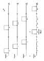
- FIG. 5shows a design of an interlace reservation procedure 500.
- Terminal 110may receive forward link signals (e.g., pilots) from base stations 120 and 122 and may measure the received power of each base station (step 1).
- Terminal 110may desire to communicate with selected base station 120 and may observe high interference from interfering base station 122.
- selected base station 120may be a macro base station
- interfering base station 122may be a strong nearby femto base station with restricted association.
- the interference from base station 122may be so strong that it may desens the receiver at terminal 110.
- Terminal 110may report its interference condition to selected base station 120 (step 2).
- the interference conditionmay be conveyed by a pilot measurement report, which may provide the received power for each base station detected by terminal 110.
- Terminal 110may be able to exchange messages with selected base station 120 on certain resources that may be cleared of interference from interfering base station 122, as described below.
- Selected base station 120may receive the interference report from terminal 110 and may determine that terminal 110 is observing high interference.
- Base station 120may then send a reservation request to interfering base station 122 (step 3).
- the requestmay indicate that base station 120 desires to reserve one or more interlaces on each link and may also provide information indicating the urgency of the request, the number of interlaces to reserve, which interlaces to reserve, etc.
- Interfering base station 122may receive the request and decide whether to grant or dismiss the request (step 4). The decision may be based on various factors such as priority information in the request, loading at interfering base station 122, etc.
- Interfering base station 122may grant all, some, or none of the interlaces requested by base station 120. The granted interlace(s), if any, may be reserved for base station 120 and may not be used by interfering base station 122.
- Interfering base station 122may send a reservation response containing its decision to selected base station 120 (step 5).
- the responsemay indicate the reserved interlaces for base station 120, the time period over which the reserved interlaces are valid, etc.
- Selected base station 120may then communicate with terminal 110 on the reserved interlaces (step 6).
- FIG. 5shows a design in which selected base station 120 sends a request to reserve interlaces.
- terminal 110may initiate interlace reservation by sending a message to selected base station 120 or interfering base station 122.
- An interlace reservationmay be valid for a certain period of time, which may be referred to as a reservation period.
- the reservation periodmay be a predetermined time period, which may be known a priori by both base stations 120 and 122 and may not need to be conveyed in the reservation request or response.
- the reservation periodmay be determined by selected base station 120 (e.g., based on data requirements and/or other factors) and sent in the reservation request.
- the reservation periodmay be decided by interfering base station 122 and sent in the reservation response.
- the reservation requestmay provide a requested reservation period, and the reservation response may provide a granted reservation period, which may be all or a fraction of the requested reservation period.
- interfering base station 122may transmit on the reserved interlaces. The interlace reservation procedure may then be repeated to reserve interlaces for serving base station 120.
- the interlace reservation procedure in FIG. 5assumes that terminal 110 can communicate over the air with selected base station 120, e.g., so that terminal 110 can report its interference condition.
- the interference from interfering base station 122may be sufficiently high and may desens the desired signal from selected base station 120. Furthermore, if terminal 110 wakes up from an idle state in a dominant interference scenario, then terminal 110 may not be able to detect base station 120 or to establish communication with base station 120.
- a bootstrap schememay be used to allow terminal 110 to communicate with selected base station 120 in the presence of high interference from interfering base station 122.
- the bootstrap schememay clear (i.e., to blank or vacate) a pair of interlaces that terminal 110 may use for initial communication with selected base station 120, e.g., to open a connection, to initiate interlace reservation, etc.
- a connectiontypically refers to an established communication session that allows for exchanges of data as well as signaling messages at higher layers, e.g., Layer 3 (L3).
- L3Layer 3
- a connectionmay be opened by exchanging certain signaling messages.
- FIG. 6shows a design of a bootstrap procedure 600 to clear a pair of interlaces for terminal 110.
- Terminal 110may detect high interference from interfering base station 122 and may send a request to clear interlaces to base station 122 (step 1).
- Interfering base station 122may grant the request, clear an FL interlace and an RL interlace, and avoid using the cleared interlaces (step 2).
- Interfering base station 122may send a response to inform terminal 110 of the cleared interlaces (step 3).
- terminal 110may assume that certain designated interlaces will be cleared by the request, and interfering base station 122 may not send a response. In either case, terminal 110 may communicate with selected base station 120 on the cleared interlaces to open a connection, to initiate reservation of interlaces, etc. (step 4).
- terminal 110may first open a connection with interfering base station 122.
- Base station 122may be a femto base station with restricted association and may not allow terminal 110 to send data via base station 122. However, base station 122 may allow terminal 110 to open a connection and send control information. After opening a connection, terminal 110 may send an L3 message to request base station 122 to clear a pair of interlaces. Terminal 110 may also send messages for interlace reservation during this time period. Terminal 110 may close the connection with interfering base station 122 after completing the interlace clearing and/or reservation procedure.
- terminal 110may request interfering base station 122 to clear a pair of interlaces by sending a control message at a Medium Access Control (MAC) layer, which may also be referred to as a Layer 2 (L2) message.
- the L2 messagemay be used, e.g., if terminal 110 is not allowed to open a connection with interfering base station 122.
- the L2 messagemay be sent over a control channel that may be cleared of interference from neighbor base stations.
- the L2 messagemay indicate that the clearing of interlaces is mandatory, e.g., does not depend on any priority information sent in the L2 message.
- the L2 messagemay also indicate that the clearing is valid for a predetermined time period instead of just one frame.
- the L2 messagemay also indicate a specific interlace to clear.
- Terminal 110may open a connection with serving base station 120 and may also send messages for interlace reservation using the cleared interlaces.
- the particular interlace to clear for each linkmay be determined in various manners.
- a specific interlace to clear for each linkmay be known a priori by terminal 110 and interfering base station 122, e.g., specified in a standard.
- terminal 110may indicate a specific interlace to clear for each link in an L2 or L3 message.
- Interfering base station 122may grant or deny the request for the indicated interlace. If the request is denied, then terminal 110 may follow a "trial and error" approach and may request interfering base station 122 to clear another interlace.
- terminal 110may send a list of candidate interlaces to clear for each link or for both link.
- Interfering base station 122may then select an interlace for each link from the list applicable for that link.
- terminal 110may send a request without identifying any interlace.
- Interfering base station 122may then select a specific interlace to clear for each link and may convey the cleared interlaces to terminal 110.
- interfering base station 122may advertise specific interlace(s) that it may clear for each link via a broadcast message. Terminal 110 may then request interfering base station 122 to clear one of the advertised interlace(s) for each link.
- terminal 110may send a message at any layer to request interfering base station 122 to clear or reserve interlaces.
- Terminal 110may send an L3 message after establishing a connection with interfering base station 122. There may be longer delay in sending an L3 message due to overhead to establish a connection. However, the L3 message may have certain features such as encryption, authentication of the sender of the L3 message, etc. It may be desirable to use an L3 message to clear or reserve interlaces for an extended period of time.
- terminal 110may send an L2 message without establishing a connection with interfering base station 122. There may be less delay and less overhead in sending an L2 message. However, an L2 message may be received in error. It may be desirable to avoid making a long-term decision based on an L2 message in case of an error.
- Terminal 110may be desensed by interfering base station 122 and may need to receive broadcast messages as well as paging messages from serving base station 120. This may be true even if terminal 110 is in an idle state and not actively communicating with base station 120.
- Terminal 110may send an L2 or L3 message to clear resources for receiving broadcast transmissions carrying broadcast and paging messages.
- the broadcast transmissionsmay be sent in specific frames that may be known to terminal 110.
- Terminal 110may request interfering base station 122 to clear the specific frames (and not an entire interlace) on which the broadcast transmissions are sent. These frames may be conveyed in the request or may be known to interfering base station 122.
- a reserved interlacemay comprise periodic frames (e.g., as shown in FIG. 2 ) whereas the reserved frames or time intervals may or may not be periodic.
- the time reservation techniques described hereinmay be used to combat high interference between two or more base stations that may cause desens at terminal 110.
- the base stationsmay be of different types, e.g., a macro base station and a femto base station.
- the base stationsmay also be of the same type, e.g., two femto base stations.
- terminal 110may not be able to detect selected base station 120 in a dominant interference scenario.
- each base stationmay transmit a low reuse preamble (LRP) signal with time reuse.
- the time reusemay be achieved with (i) random time reuse where time periods for LRP signals from different base stations are pseudo-randomly selected or (ii) fixed time reuse where time periods for the LRP signals are pre-assigned, e.g., to be non-overlapping.
- Terminal 110may be able to receive the LRP signal from selected base station 120 at a different time from the LRP signal of interfering base station 122. Detection of base stations may thus be enabled based on time reuse (possibly in addition to frequency reuse) of the LRP signals.
- FIG. 7shows a design of a process 700 performed by a terminal for communication in an interference dominant scenario.
- the terminalmay measure received power of base stations (block 712).
- the terminalmay report interference condition observed by the terminal (block 714).
- the terminalmay send the measured received power and an identifier (ID) of an interfering base station to a serving/selected base station.
- IDan identifier
- the interference conditionmay also be conveyed in other manners.
- the terminalmay communicate with the serving base station in time intervals reserved for the serving base station based on the reported interference condition (block 716).
- the reserved time intervalsmay have reduced (e.g., low or no) interference from the interfering base station and may correspond to frames in at least one interlace reserved for the serving base station.
- the terminalmay detect for the serving base station based on an LRP signal sent by the serving base station with time reuse.
- the serving base stationmay send its LRP signal in time periods that may be non-overlapping or pseudo-random with respect to time periods used for an LRP signal sent by the interfering base station.
- the terminalmay also detect for the serving base station after performing bootstrapping, as described above.
- the terminalmay measure the received power of different base stations based on the LRP signals, pilots, and/or other transmissions from these base stations.
- the terminalmay exchange messages with the serving base station and/or the interfering base station to reserve time intervals for the serving base station.
- the serving and interfering base stationsmay exchange messages to reserve time intervals for the serving base station, e.g., as shown in FIG. 5 .
- the terminalmay send a message to the interfering base station to request the interfering base station to clear some time intervals.
- the messagemay comprise an L2 message or an L3 message.
- the terminalmay then exchange messages with the serving base station in the cleared time intervals to open a connection with the serving base station.
- the reserved time intervalsmay comprise first time intervals reserved for the forward link and second time intervals reserved for the reverse link.
- the terminalmay receive forward link data and control information from the serving base station in the first time intervals.
- the terminalmay send reverse link data and control information to the serving base station in the second time intervals.
- the terminalmay also receive broadcast transmissions from the serving base station in time intervals having reduced interference from the interfering base station.
- the terminalmay communicate with the serving base station on all or a subset of the frequency resources in the reserved time intervals.
- the remaining frequency resources (if any) in the reserved time intervalsmay be (i) unused by the interfering base station if the terminal is observing high interference from the interfering base station or (ii) usable by the interfering base station if the terminal is not observing high interference from the interfering base station.
- the interfering base stationmay have higher transmit power and higher pathloss than the transmit power and pathloss of the serving base station.
- the interfering base stationmay have restricted association, and the terminal may not be allowed to connect to the interfering base station.
- FIG. 8shows a design of an apparatus 800 for a terminal.
- Apparatus 800includes a module 812 to measure received power of base stations, a module 814 to report interference condition observed by the terminal, and a module 816 to communicate with a serving base station in time intervals reserved for the serving base station based on the reported interference condition, with the reserved time intervals having reduced interference from an interfering base station.
- FIG. 9shows a design of a process 900 performed by a serving base station for communication with a terminal operating in an interference dominant scenario.
- the serving base stationmay receive a report of interference condition observed by the terminal (block 912).
- the serving base stationmay determine time intervals reserved for it based on the interference condition observed by the terminal (block 914).
- the reserved time intervalsmay have reduced interference from an interfering base station.
- the serving base stationmay communicate with the terminal in the reserved time intervals (block 916).
- the serving base stationmay reserve time intervals if the report indicates that the terminal is observing high interference from the interfering base station.
- the terminalmay observe high interference if the received power for the interfering base station at the terminal exceeds a threshold, which may indicate that the terminal may be desensed by the interfering base station.
- the serving base stationmay reserve time and frequency resources for communication with the terminal if the report indicates that the terminal is not observing high interference from the interfering base station.
- the serving and interfering base stationsmay send transmissions on different frequency resources in the same time interval since the transmission from the interfering base station would not desens the terminal.
- the serving base stationmay send a request for reserved time intervals to the interfering base station, e.g., as shown in FIG. 5 .
- the serving base stationmay then receive a response from the interfering base station.
- the serving base stationmay determine time intervals cleared by the interfering base station.
- the terminalmay initiate clearing of time intervals and may inform the serving base station of the cleared time intervals.
- the serving base stationmay exchange messages with the terminal in the cleared time intervals to open a connection for the terminal.
- the serving base stationmay send a message to the interfering base station to request the interfering base station to reduce (e.g., lower or avoid) interference in time intervals used for broadcast transmissions.
- the serving base stationmay send broadcast transmissions in the cleared time intervals having reduced interference from the interfering base station.
- FIG. 10shows a design of an apparatus 1000 for a serving base station.
- Apparatus 1000includes a module 1012 to receive a report of interference condition observed by a terminal, a module 1014 to determine time intervals reserved for the serving base station based on the interference condition observed by the terminal, with the reserved time intervals having reduced interference from an interfering base station, and a module 1016 to communicate with the terminal in the reserved time intervals.
- FIG. 11shows a design of a process 1100 performed by an interfering base station.
- the interfering base stationmay receive a request for reserved time intervals for a serving base station (block 1112).
- the requestmay be sent by the serving base station or a terminal based on interference condition observed by the terminal.
- the interfering base stationmay reserve time intervals for the serving base station in response to the request (block 1114).
- the interfering base stationmay send a response to the serving base station.
- the interfering base stationmay reduce (e.g., lower or avoid) interference in the reserved time intervals (block 1116). In one design of block 1116, the interfering base station may avoid transmission in the reserved time intervals. In another design, the interfering base station may send transmission at a lower transmit power level in the reserved time intervals. In yet another design, the interfering base station may perform beamsteering for transmission sent in the reserved time intervals to steer the transmission in a direction different from the terminal.
- the interfering base stationmay receive a message from the terminal to request the interfering base station to clear some time intervals for use by the terminal for initial communication, e.g., to open a connection with the serving base station.
- the interfering base stationmay reduce interference in the cleared time intervals.
- the interfering base stationmay also receive a message from the serving base station or the terminal to request the interfering base station to clear time intervals in which the serving base station will send broadcast transmissions.
- the interfering base stationmay reduce interference in the time intervals used for broadcast transmissions.
- FIG. 12shows a design of an apparatus 1200 for an interfering base station.
- Apparatus 1200includes a module 1212 to receive a request for reserved time intervals for a serving base station, a module 1214 to reserve time intervals for the serving base station based on interference condition observed by a terminal, and a module 1216 to reduce interference in the reserved time intervals by an interfering base station.
- the modules in FIGS. 8 , 10 and 12may comprise processors, electronics devices, hardware devices, electronics components, logical circuits, memories, etc., or any combination thereof.
- FIG. 13shows a block diagram of a design of terminal 110, serving base station 120, and interfering base station 122.
- a transmit processor 1314amay receive data from a data source 1312a and control information from a controller/processor 1330a and a scheduler 1334a. Controller/processor 1330a may provide messages for time/interlace reservation. Scheduler 1334a may provide grants for terminal 120.
- Transmit processor 1314amay process (e.g., encode and symbol map) the data, control information, and pilot and provide data symbols, control symbols, and pilot symbols, respectively.
- a modulator (MOD) 1316amay process the data, control, and pilot symbols (e.g., for OFDM, CDMA, etc.) and provide output samples.
- a transmitter (TMTR) 1318amay condition (e.g., convert to analog, amplify, filter, and upconvert) the output samples and generate a forward link signal, which may be transmitted via an antenna 1320a.
- Interfering base station 122may similarly process data and control information for the terminals served by base station 122.
- the data, control information, and pilotmay be processed by a transmit processor 1314b, further processed by a modulator 1316b, conditioned by a transmitter 1318b, and transmitted via an antenna 1320b.
- an antenna 1352may receive the forward link signals from base stations 120 and 122.
- a receiver (RCVR) 1354may condition (e.g., filter, amplify, downconvert, and digitize) a received signal from antenna 1352 and provide input samples.
- a demodulator (DEMOD) 1356may process the input samples (e.g., for OFDM, CDMA, etc.) and provide detected symbols.
- a receive processor 1358may process (e.g., symbol demap and decode) the detected symbols, provide decoded data to a data sink 1360, and provide decoded control information to a controller/processor 1370.
- a transmit processor 1382may receive and process data from a data source 1380 and control information (e.g., messages for time/interlace reservation) from controller/processor 1370.
- a modulator 1384may process the symbols from processor 1382 (e.g., for OFDM, SC-FDM, CDMA, etc.) and provide output samples.
- a transmitter 1386may condition the output samples and generate a reverse link signal, which may be transmitted via antenna 1352.
- the reverse link signals from terminal 110 and other terminalsmay be received by antenna 1320, conditioned by a receiver 1340, demodulated by a demodulator 1342, and processed by a receive processor 1344.
- Processor 1344may provide decoded data to a data sink 1346 and decoded control information to controller/processor 1330.
- Controllers/processors 1330a, 1330b and 1370may direct the operation at base stations 120 and 122 and terminal 110, respectively. Controller/processor 1370 at terminal 110 may perform or direct process 700 in FIG. 7 and/or other processes for the techniques described herein. Controller/processor 1330a at serving base station 120 may perform or direct process 900 in FIG. 9 and/or other processes for the techniques described herein. Controller/processor 1330b at interfering base station 122 may perform or direct process 1100 in FIG. 11 and/or other processes for the techniques described herein.
- Memories 1332a, 1332b and 1372may store data and program codes for base stations 120 and 122 and terminal 110, respectively. Schedulers 1334a and 1334b may schedule terminals for communication with base stations 120 and 122, respectively, and may assign resources to the scheduled terminals.
- DSPdigital signal processor
- ASICapplication specific integrated circuit
- FPGAfield programmable gate array
- a general-purpose processormay be a microprocessor, but in the alternative, the processor may be any conventional processor, controller, microcontroller, or state machine.
- a processormay also be implemented as a combination of computing devices, e.g., a combination of a DSP and a microprocessor, a plurality of microprocessors, one or more microprocessors in conjunction with a DSP core, or any other such configuration.
- a software modulemay reside in RAM memory, flash memory, ROM memory, EPROM memory, EEPROM memory, registers, hard disk, a removable disk, a CD-ROM, or any other form of storage medium known in the art.
- An exemplary storage mediumis coupled to the processor such that the processor can read information from, and write information to, the storage medium.
- the storage mediummay be integral to the processor.
- the processor and the storage mediummay reside in an ASIC.
- the ASICmay reside in a user terminal.
- the processor and the storage mediummay reside as discrete components in a user terminal.
- the functions describedmay be implemented in hardware, software, firmware, or any combination thereof. If implemented in software, the functions may be stored on or transmitted over as one or more instructions or code on a computer-readable medium.
- Computer-readable mediaincludes both computer storage media and communication media including any medium that facilitates transfer of a computer program from one place to another.
- a storage mediamay be any available media that can be accessed by a general purpose or special purpose computer.
- such computer-readable mediacan comprise RAM, ROM, EEPROM, CD-ROM or other optical disk storage, magnetic disk storage or other magnetic storage devices, or any other medium that can be used to carry or store desired program code means in the form of instructions or data structures and that can be accessed by a general-purpose or special-purpose computer, or a general-purpose or special-purpose processor. Also, any connection is properly termed a computer-readable medium.
- Disk and discincludes compact disc (CD), laser disc, optical disc, digital versatile disc (DVD), floppy disk and blu-ray disc where disks usually reproduce data magnetically, while discs reproduce data optically with lasers. Combinations of the above should also be included within the scope of computer-readable media.
Landscapes
- Engineering & Computer Science (AREA)
- Computer Networks & Wireless Communication (AREA)
- Signal Processing (AREA)
- Quality & Reliability (AREA)
- Mobile Radio Communication Systems (AREA)
- Detection And Prevention Of Errors In Transmission (AREA)
Description
- The present disclosure relates generally to communication, and more specifically to transmission techniques for a wireless communication network.
- Wireless communication networks are widely deployed to provide various communication content such as voice, video, packet data, messaging, broadcast, etc. These wireless networks may be multiple-access networks capable of supporting multiple users by sharing the available network resources. Examples of such multiple-access networks include Code Division Multiple Access (CDMA) networks, Time Division Multiple Access (TDMA) networks, Frequency Division Multiple Access (FDMA) networks, Orthogonal FDMA (OFDMA) networks, and Single-Carrier FDMA (SC-FDMA) networks.
- A wireless communication network may include a number of base stations that can support communication for a number of terminals. A terminal may communicate with a serving base station via the forward and reverse links. The forward link (or downlink) refers to the communication link from the base station to the terminal, and the reverse link (or uplink) refers to the communication link from the terminal to the base station.
- The serving base station may transmit data to the terminal on the forward link and/or may receive data from the terminal on the reverse link. On the forward link, the terminal may observe high interference from a neighbor base station and may be unable to correctly decode a data transmission from the serving base station. On the reverse link, a data transmission from the terminal may cause high interference to the neighbor base station, which may then be unable to correctly decode data transmissions sent by other terminals to the neighbor base station.
- The International Patent application
WO 2005/062798 A2 discloses a personal base station (PBS 1) configured to connect to the Internet and establish a small area of wireless coverage including means for controlling interference with neighboring personal base stations (PBS 2) using a timeslot management mechanism. Timeslot management mechanisms include timeslot interference detection, timeslot power reduction, timeslot allocation, timeslot offset calibration, and timeslot synchronization management that minimizes the number of frequencies required to control inter-cell interference between neighboring personal base stations. - The European
patent application EP 1 489 868 A1 relates to a TDMA radio communication system wherein a first radio station carries out communications by selectively modulating a subcarrier with which a desired transmission rate can be obtained in the second radio station. - There is therefore a need in the art for techniques to combat high interference in order to improve performance.
- The invention is defined by the independent claims.
- Techniques for combating high interference in a dominant interference scenario are described herein. A terminal may observe high interference from an interfering base station in a dominant interference scenario. The interference may be so high that the terminal may not be able to receive a desired signal from a serving/selected base station.
- In an aspect, high interference in a dominant interference scenario may be combated by reserving time intervals for the serving base station. The reserved time intervals may correspond to frames in one or more interlaces and may have reduced (e.g., low or no) interference from the interfering base station. The terminal may communicate with the serving base station in the reserved time intervals and may be able to avoid high interference that may desens a receiver at the terminal.
- In one design, the terminal may measure received power of base stations and may report its interference condition. The serving base station may receive a report of the interference condition observed by the terminal and may reserve time intervals for itself if the report indicates that the terminal is observing high interference. The serving base station may send a reservation request to the interfering base station to reserve time intervals. The interfering base station may grant the request and send a response to the serving base station. The serving base station may thereafter communicate with the terminal in the reserved time intervals.
- The terminal may not be able to detect the serving base station or to open a connection with the serving base station prior to reservation of time intervals. In one design, the terminal may detect high interference from the interfering base station and may initiate clearing of some time intervals in order to detect and communicate with the serving base station. The terminal may send a message to the interfering base station to request it to clear some time intervals. The terminal may then exchange messages with the serving base station in the cleared time intervals to open a connection with the serving base station. The serving base station or the terminal may then initiate reservation of time intervals for the serving base station. The cleared time intervals may be valid for a short period whereas the reserved time intervals may be valid for an extended period.
- Various aspects and features of the disclosure are described in further detail below.
FIG. 1 shows a wireless communication network.FIG. 2 shows an interlace transmission structure.FIG. 3A shows data transmission on the forward link.FIG. 3B shows data transmission on the reverse link.FIG. 4 shows an example of reserved interlaces for a base station.FIG. 5 shows an interlace reservation procedure.FIG. 6 shows an interlace clearing procedure.FIGS. 7 and 8 show a process and an apparatus, respectively, for a terminal operating in an interference dominant scenario.FIGS. 9 and 10 show a process and an apparatus, respectively, for a serving base station in an interference dominant scenario.FIGS. 11 and 12 show a process and an apparatus, respectively, for an interfering base station in an interference dominant scenario.FIG. 13 shows a block diagram of the terminal, the serving base station, and the interfering base station.- The techniques described herein may be used for various wireless communication networks such as CDMA, TDMA, FDMA, OFDMA, SC-FDMA and other networks. The terms "network" and "system" are often used interchangeably. A CDMA network may implement a radio technology such as Universal Terrestrial Radio Access (UTRA), cdma2000, etc. UTRA includes Wideband CDMA (WCDMA) and other variants of CDMA. cdma2000 covers IS-2000, IS-95 and IS-856 standards. A TDMA network may implement a radio technology such as Global System for Mobile Communications (GSM). An OFDMA network may implement a radio technology such as Evolved UTRA (E-UTRA), Ultra Mobile Broadband (UMB), IEEE 802.11 (Wi-Fi), IEEE 802.16 (WiMAX), IEEE 802.20, Flash-OFDM®, etc. UTRA and E-UTRA are part of Universal Mobile Telecommunication System (UMTS). 3GPP Long Term Evolution (LTE) is an upcoming release of UMTS that uses E-UTRA, which employs OFDMA on the downlink and SC-FDMA on the uplink. UTRA, E-UTRA, UMTS, LTE and GSM are described in documents from an organization named "3rd Generation Partnership Project" (3GPP). cdma2000 and UMB are described in documents from an organization named "3rd Generation Partnership Project 2" (3GPP2).
FIG. 1 shows awireless communication network 100, which may include a number of base stations and other network entities. For simplicity,FIG. 1 shows only twobase stations network controller 150. A base station may be a fixed station that communicates with the terminals and may also be referred to as an access point, a Node B, an evolved Node B (eNB), etc. A base station may provide communication coverage for a particular geographic area. The overall coverage area of a base station may be partitioned into smaller areas, and each smaller area may be served by a respective base station subsystem. The term "cell" can refer to a coverage area of a base station and/or a base station subsystem serving this coverage area, depending on the context in which the term is used.- A base station may provide communication coverage for a macro cell, a pico cell, a femto cell, or some other type of cell. A macro cell may cover a relatively large geographic area (e.g., several kilometers in radius) and may support communication for all terminals with service subscription in the wireless network. A pico cell may cover a relatively small geographic area and may support communication for all terminals with service subscription. A femto cell may cover a relatively small geographic area (e.g., a home) and may support communication for terminals having association with the femto cell (e.g., terminals belonging to residents of the home). The terminals supported by a femto cell may belong in a closed subscriber group (CSG). A base station for a macro cell may be referred to as a macro base station. A base station for a pico cell may be referred to as a pico base station. A base station for a femto cell may be referred to as a femto base station or a home base station.
Network controller 150 may couple to a set of base stations and provide coordination and control for these base stations.Network controller 150 may communicate withbase stations Base stations - A terminal 110 may be one of many terminals supported by
wireless network 100.Terminal 110 may be stationary or mobile and may also be referred to as an access terminal (AT), a mobile station (MS), a user equipment (UE), a subscriber unit, a station, etc.Terminal 110 may be a cellular phone, a personal digital assistant (PDA), a wireless modem, a wireless communication device, a handheld device, a laptop computer, a cordless phone, a wireless local loop (WLL) station, etc. Terminal 110 may communicate with a serving base station and may cause interference to and/or receive interference from one or more interfering base stations. A serving base station is a base station designated to serve a terminal on the forward and/or reverse link. An interfering base station is a base station causing interference to a terminal on the forward link and/or observing interference from the terminal on the reverse link. InFIG. 1 ,base station 120 is a selected base station forterminal 110 prior to system access and is a serving base station forterminal 110 after system access.Base station 122 is an interfering base station toterminal 110.FIG. 2 shows aninterlace transmission structure 200 that may be used for each of the forward and reverse links. The transmission timeline may be partitioned into units of frames. Each frame may cover a particular time duration, e.g., 1 milliseconds (ms). A frame may also be referred to as a subframe, a slot, etc.- M interlaces with indices of 0 through M -1 may be defined, where M may be equal to 4, 6, 8 or some other value. Each interlace may include frames that are spaced apart by M frames. For example,
interlace 0 may includeframes 0, M, 2M, etc.,interlace 1 may includeframes 1, M + 1, 2M + 1, etc., as shown inFIG. 2 . The interlaces may be used for hybrid automatic retransmission (HARQ) and may be referred to as HARQ interlaces. For HARQ, one or more transmissions may be sent for a packet until the packet is decoded correctly or some other termination condition is encountered. All transmissions of the packet may be sent in different frames of a single interlace. - The interlaces for the forward link may be referred to as forward link (FL) interlaces, and the interlaces for the reverse link may be referred to as reverse link (RL) interlaces. In one design, the M FL interlaces may be associated with the M RL interlaces based on a one-to-one mapping. For example, FL interlace m may be associated with RL interlacer = {(m + Q) mod M}, where Q is an offset (in number of frames) between the FL interlace and the associated RL interlace, and "mod" denotes a modulo operation. In one design, Q may be equal to M/2, and each FL interlace may be associated with a corresponding RL interlace that is M/2 frames away.
- A pair of interlaces composed of an FL interlace and an associated RL interlace may support data transmission on both the forward and reverse links. For data transmission on the forward link, data and control information may be sent in frames of the FL interlace, and control/feedback information may be sent in frames of the associated RL interlace. For data transmission on the reverse link, data and control information may be sent in frames of the RL interlace, and control/feedback information may be sent in frames of the associated FL interlace. In general, control information may comprise any information used to support data transmission, e.g., channel information, grant information, feedback information, etc.
FIG. 3A shows data transmission on the forward link with one pair of interlaces, e.g., RL interlacem and FL interlacem +Q. Terminal 110 may periodically estimate the forward link channel quality for servingbase station 120 and may send channel quality indicator (CQI) information in framem of RL interlacem.Base station 120 may use the CQI information and/or other information to schedule terminal 110 for data transmission on the forward link and to select a modulation and coding scheme (MCS).Base station 120 may send an FL grant and data in framem + Q of FL interlacem + Q. The FL grant may include the selected MCS, the assigned resources, etc.Terminal 110 may process the data transmission frombase station 120 in accordance with the FL grant and, depending on the decoding result, may send an acknowledgement (ACK) or a negative acknowledgement (NAK) in framem +M. Base station 120 may retransmit the data if a NAK is received and may transmit new data if an ACK is received. Data transmission on the forward link and ACK/NAK feedback on the reverse link may continue in similar manner.FIG. 3B shows data transmission on the reverse link with one pair of interlaces, e.g., RL interlacem and FL interlacem +Q. Terminal 110 may have data to send to servingbase station 120 and may send a resource request in framem of RL interlacem.Base station 120 may schedule terminal 110 for data transmission on the reverse link and may send an RL grant in framem + Q of FL interlacem + Q. The RL grant may include the selected MCS, the assigned resources, etc.Terminal 110 may send a data transmission in accordance with the RL grant in framem +M. Base station 120 may process the data transmission fromterminal 110 and, depending on the decoding result, may send an ACK or a NAK in framem + M +Q. Terminal 110 may retransmit the data if a NAK is received and may transmit new data if an ACK is received. Data transmission on the reverse link and ACK/NAK feedback on the forward link may continue in similar manner.- As shown in
FIGS. 3A and 3B , a pair of interlaces may support data transmission on the forward and/or reverse link. In one design, data transmission on the forward and reverse links may occur in different frames. In another design, data transmission on the forward and reverse links may occur in the same frame, e.g., using frequency division multiplexing (FDM), time division multiplexing (TDM), etc. - In general, data transmission on a first link may be supported with (i) one or more interlaces on the first link to send data and control information and (ii) one or more interlaces on a second link to send control/feedback information. The number of interlaces to use on each link may be dependent on the amount of data and control information to send on that link, the availability of interlaces for that link, etc. Data may be sent on one or multiple interlaces on the first link, and control/feedback information may be sent on one interlace on the second link.
Terminal 110 may operate in a dominant interference scenario, which may occur due to various reasons. For example, a dominant interference scenario may occur due to base stations transmitting at very different power levels, e.g., 20 Watts for macro base stations versus 1 Watt for pico and femto base stations.Terminal 110 may receive signals from twobase stations base station 120 thanbase station 122. Nevertheless, terminal 110 may desire to connect tobase station 120 if the pathloss forbase station 120 is lower than the pathloss forbase station 122. This may be the case ifbase station 120 is a pico or femto base station (not shown inFIG. 1 ) and has significantly lower transmit power as compared tobase station 122, which may be a macro base station (also not shown inFIG. 1 ).Terminal 110 may prefer to connect tobase station 120 with lower received power since less interference may be caused to the network to achieve a given data rate.- A dominant interference scenario may also occur due to restricted association.
Terminal 110 may be very close tobase station 122 and may have the strongest channel and the highest received power forbase station 122. However, terminal 110 may not belong in a CSG ofbase station 122 and may not be allowed to connect tobase station 122.Terminal 110 may then connect to lower receivedpower base station 120 and may observe high interference frombase station 122. Terminal 110 may observe high interference in a dominant interference scenario. The interference may be so high or strong that it may desensitize a receiver withinterminal 110.Terminal 110 may perform automatic gain control (AGC) and may adjust a receiver gain such that an input signal provided to an analog-to-digital converter (ADC) within the receiver is at a target signal level in order to avoid clipping the ADC. The ADC input signal may comprise a desired signal from serving/selectedbase station 120 as well as high interference from interferingbase station 122. The ADC input signal may be dominated by the high interference, and the desired signal level may be below the quantization noise level of the ADC. In this case, even if interferingbase station 122 transmits on different frequency resources (e.g., a different set of subcarriers) as compared to servingbase station 120, terminal 110 will still be unable to receive the desired signal frombase station 120 since the desired signal will be masked by the ADC quantization noise. The high interference may thus desensitize the ADC ofterminal 110.Terminal 110 may be unable to receive the desired signal from servingbase station 120 in such a desens scenario.Terminal 110 may be connected to servingbase station 120 and may be desensed by interferingbase station 122 on the forward link. It is likely thatbase station 122 will in turn be desensed byterminal 110 on the reverse link.Terminal 110 may thus be a victim on the forward link and an aggressor on the reverse link. Conversely,base station 122 may be an aggressor on the forward link and a victim on the reverse link. In such a symmetric desens scenario, neither terminal 110 norbase station 122 may be able to send data on the forward link or the reverse link. This is because transmission of data on one link typically requires transmission of control feedback information (e.g., ACK/NAK) on the other link, as shown inFIGS. 3A and 3B . For example, even thoughterminal 110 may be a victim on only the forward link, terminal 110 may not be able to send data on the reverse link data because it cannot receive control/feedback information on the forward link.- In an aspect, desens of
terminal 110 in a dominant interference scenario may be combated by reserving time intervals (e.g., a set of interlaces) for servingbase station 120. The reserved time intervals may have low or no interference from interferingbase station 122 and may be used for communication betweenterminal 110 and servingbase station 120. This may allow terminal 110 to receive the desired signal from servingbase station 120 and to avoid high interference from interferingbase station 122. - In general, time given in any units may be reserved for serving
base station 120. For clarity, much of the description below is for reservation of a set of interlaces, which may be referred to as a reserved set. The reserved set may include one or more FL interlaces that are reserved forbase station 120. In one design, interferingbase station 122 may avoid using (i.e., blank transmission on) the reserved FL interlace(s) so that terminal 110 can observe no interference frombase station 122 on the reserved FL interlace(s). In another design, interferingbase station 122 may send transmissions on the reserved FL interlace(s) in a manner such thatterminal 110 can observe low or no interference frombase station 122 on the reserved FL interlace(s). For example, interferingbase station 122 may reduce its transmit power on the reserved FL interlace(s). Interferingbase station 122 may also steer its power in a direction different from terminal 110, e.g., by placingterminal 110 in a spatial null. - Beamsteering may be performed based on spatial information, which may comprise precoding weights (e.g., a precoding matrix or vector), a channel estimate, and/or other information used by a transmitter to spatially steer its power. The spatial information may be obtained or provided in various manners. In one design, a spatial channel between interfering
base station 122 and terminal 110 may be known tobase station 122, e.g., on a long-term basis. In another design, terminal 110 may send to interfering base station 122 a message containing information on the spatial channel or a preferred beam betweenbase station 122 andterminal 110. In yet another design, reciprocity between the forward and reverse links may be assumed, e.g., due to use of time division duplexing (TDD). Interferingbase station 122 may then estimate a reverse link channel forterminal 110 and may use the reverse link channel estimate as a forward link channel estimate. For all of the designs, interferingbase station 122 may derive precoding weights based on information on the spatial channel or may be provided with the precoding weights. Interferingbase station 122 may then perform beamsteering with the precoding weights. - The reserved set may also include one or more RL interlace(s) that are reserved for
terminal 110/servingbase station 120.Terminal 110 may send data and/or control information in the reserved RL interlace(s) to servingbase station 120. Interferingbase station 122 may avoid using the reserved RL interlace(s) since it may observe high interference fromterminal 110 on the reserved RL interlace(s). - In one design, the reserved FL interlace(s) and the reserved RL interlace(s) may be paired with one other. In this design, the number of reserved FL interlaces is equal to the number of reserved RL interlaces. The pairing may be such that a reserved FL interlace can carry data and a reserved RL interlace can carry control/feedback information to support data transmission, and vice versa, e.g., as shown in
FIGS. 3A and 3B . A reserved FL interlace may be separated by M/2 frames from a reserved RL interlace. For example, with M = 8,FL interlace 0 may be associated withRL interlace 4,FL interlace 1 may be associated withRL interlace 5, etc. FIG. 4 shows an example of an interlace reservation. In this example, M = 8, and eight FL interlaces 0 through 7 and eight RL interlaces 0 through 7 may be available. Eight pairs of interlaces may be defined. Pair A may includeFL interlace 0 andRL interlace 4, pair B may includeFL interlace 1 andRL interlace 5, and so on, and pair H may includeFL interlace 7 andRL interlace 3.- In the example shown in
FIG. 4 , interlace pairs A and D are reserved forbase station 120.Base station 120 may transmit data and control information on FL interlaces 0 and 3 and may receive data and control information on RL interlaces 4 and 7 in reserved pairs A and D. Interlace pairs B, C, E, F, G and H are not reserved forbase station 120.Base station 120 and/or 122 may transmit data and control information on FL interlaces 1, 2, 4, 5, 6 and 7 and may receive data and control information on RL interlaces 0, 1, 2, 3, 5 and 6 in pairs B, C, E, F, G and H. - For the design shown in
FIG. 4 , the reservation granularity may be in units of interlaces for each of the forward and reverse links. For a case of 8 interlaces, the reservation granularity may be 1/8 = 12.5%. In one design, the interlace reservation may be symmetric so that the number of reserved FL interlaces is equal to the number of reserved RL interlaces. In another design, the interlace reservation may be performed independently for each link. For this design, the number of reserved FL interlaces may or may not be equal to the number of reserved RL interlaces. In general, any number of interlaces may be reserved for each link and may be dependent on various factors such as the loading of all affected base stations, the priority of data and/or control information to send, etc. - In one design, different sets of interlaces may be reserved for
base stations - In another design, a set of interlaces may be reserved for serving
base station 120. Interferingbase station 122 may avoid, reduce or steer transmission on the set of interlaces reserved forbase station 120. The unreserved interlaces may be used by any base station for transmission. In the example shown inFIG. 4 , onlybase station 120 may use interlace pairs A and D, andbase stations base station 122, if needed. - Reservation of interlaces may be performed in various manners. In one design, the base stations may communicate with one another (e.g., via the backhaul or through a terminal) to reserve interlaces. In one design, interlace reservation may be achieved using upper-layer messages, which may be Layer 3 (L3) messages.
Layer 3 may be responsible for resource partitioning and allocation inwireless network 100. FIG. 5 shows a design of aninterlace reservation procedure 500.Terminal 110 may receive forward link signals (e.g., pilots) frombase stations Terminal 110 may desire to communicate with selectedbase station 120 and may observe high interference from interferingbase station 122. For example, selectedbase station 120 may be a macro base station, and interferingbase station 122 may be a strong nearby femto base station with restricted association. The interference frombase station 122 may be so strong that it may desens the receiver atterminal 110.Terminal 110 may report its interference condition to selected base station 120 (step 2). The interference condition may be conveyed by a pilot measurement report, which may provide the received power for each base station detected byterminal 110.Terminal 110 may be able to exchange messages with selectedbase station 120 on certain resources that may be cleared of interference from interferingbase station 122, as described below.- Selected
base station 120 may receive the interference report fromterminal 110 and may determine that terminal 110 is observing high interference.Base station 120 may then send a reservation request to interfering base station 122 (step 3). The request may indicate thatbase station 120 desires to reserve one or more interlaces on each link and may also provide information indicating the urgency of the request, the number of interlaces to reserve, which interlaces to reserve, etc. Interferingbase station 122 may receive the request and decide whether to grant or dismiss the request (step 4). The decision may be based on various factors such as priority information in the request, loading at interferingbase station 122, etc. Interferingbase station 122 may grant all, some, or none of the interlaces requested bybase station 120. The granted interlace(s), if any, may be reserved forbase station 120 and may not be used by interferingbase station 122. - Interfering
base station 122 may send a reservation response containing its decision to selected base station 120 (step 5). The response may indicate the reserved interlaces forbase station 120, the time period over which the reserved interlaces are valid, etc. Selectedbase station 120 may then communicate withterminal 110 on the reserved interlaces (step 6). FIG. 5 shows a design in which selectedbase station 120 sends a request to reserve interlaces. In another design, terminal 110 may initiate interlace reservation by sending a message to selectedbase station 120 or interferingbase station 122.- An interlace reservation may be valid for a certain period of time, which may be referred to as a reservation period. In one design, the reservation period may be a predetermined time period, which may be knowna priori by both
base stations base station 122 and sent in the reservation response. For example, the reservation request may provide a requested reservation period, and the reservation response may provide a granted reservation period, which may be all or a fraction of the requested reservation period. In any case, after the reservation period has elapsed, interferingbase station 122 may transmit on the reserved interlaces. The interlace reservation procedure may then be repeated to reserve interlaces for servingbase station 120. - The interlace reservation procedure in
FIG. 5 assumes that terminal 110 can communicate over the air with selectedbase station 120, e.g., so that terminal 110 can report its interference condition. The interference from interferingbase station 122 may be sufficiently high and may desens the desired signal from selectedbase station 120. Furthermore, ifterminal 110 wakes up from an idle state in a dominant interference scenario, then terminal 110 may not be able to detectbase station 120 or to establish communication withbase station 120. - A bootstrap scheme may be used to allow terminal 110 to communicate with selected
base station 120 in the presence of high interference from interferingbase station 122. The bootstrap scheme may clear (i.e., to blank or vacate) a pair of interlaces that terminal 110 may use for initial communication with selectedbase station 120, e.g., to open a connection, to initiate interlace reservation, etc. A connection typically refers to an established communication session that allows for exchanges of data as well as signaling messages at higher layers, e.g., Layer 3 (L3). A connection may be opened by exchanging certain signaling messages. FIG. 6 shows a design of abootstrap procedure 600 to clear a pair of interlaces forterminal 110.Terminal 110 may detect high interference from interferingbase station 122 and may send a request to clear interlaces to base station 122 (step 1). Interferingbase station 122 may grant the request, clear an FL interlace and an RL interlace, and avoid using the cleared interlaces (step 2). Interferingbase station 122 may send a response to informterminal 110 of the cleared interlaces (step 3). Alternatively, terminal 110 may assume that certain designated interlaces will be cleared by the request, and interferingbase station 122 may not send a response. In either case, terminal 110 may communicate with selectedbase station 120 on the cleared interlaces to open a connection, to initiate reservation of interlaces, etc. (step 4).- In a first bootstrap scheme, terminal 110 may first open a connection with interfering
base station 122.Base station 122 may be a femto base station with restricted association and may not allow terminal 110 to send data viabase station 122. However,base station 122 may allow terminal 110 to open a connection and send control information. After opening a connection, terminal 110 may send an L3 message to requestbase station 122 to clear a pair of interlaces.Terminal 110 may also send messages for interlace reservation during this time period.Terminal 110 may close the connection with interferingbase station 122 after completing the interlace clearing and/or reservation procedure. - In a second bootstrap scheme, terminal 110 may request interfering
base station 122 to clear a pair of interlaces by sending a control message at a Medium Access Control (MAC) layer, which may also be referred to as a Layer 2 (L2) message. The L2 message may be used, e.g., ifterminal 110 is not allowed to open a connection with interferingbase station 122. The L2 message may be sent over a control channel that may be cleared of interference from neighbor base stations. The L2 message may indicate that the clearing of interlaces is mandatory, e.g., does not depend on any priority information sent in the L2 message. The L2 message may also indicate that the clearing is valid for a predetermined time period instead of just one frame. The L2 message may also indicate a specific interlace to clear.Terminal 110 may open a connection with servingbase station 120 and may also send messages for interlace reservation using the cleared interlaces. - The particular interlace to clear for each link may be determined in various manners. In one design, a specific interlace to clear for each link may be knowna priori by
terminal 110 and interferingbase station 122, e.g., specified in a standard. In another design, terminal 110 may indicate a specific interlace to clear for each link in an L2 or L3 message. Interferingbase station 122 may grant or deny the request for the indicated interlace. If the request is denied, then terminal 110 may follow a "trial and error" approach and may request interferingbase station 122 to clear another interlace. In yet another design, terminal 110 may send a list of candidate interlaces to clear for each link or for both link. Interferingbase station 122 may then select an interlace for each link from the list applicable for that link. In yet another design, terminal 110 may send a request without identifying any interlace. Interferingbase station 122 may then select a specific interlace to clear for each link and may convey the cleared interlaces toterminal 110. In yet another design, interferingbase station 122 may advertise specific interlace(s) that it may clear for each link via a broadcast message.Terminal 110 may then request interferingbase station 122 to clear one of the advertised interlace(s) for each link. - In general, terminal 110 may send a message at any layer to request interfering
base station 122 to clear or reserve interlaces.Terminal 110 may send an L3 message after establishing a connection with interferingbase station 122. There may be longer delay in sending an L3 message due to overhead to establish a connection. However, the L3 message may have certain features such as encryption, authentication of the sender of the L3 message, etc. It may be desirable to use an L3 message to clear or reserve interlaces for an extended period of time. Alternatively, terminal 110 may send an L2 message without establishing a connection with interferingbase station 122. There may be less delay and less overhead in sending an L2 message. However, an L2 message may be received in error. It may be desirable to avoid making a long-term decision based on an L2 message in case of an error. Terminal 110 may be desensed by interferingbase station 122 and may need to receive broadcast messages as well as paging messages from servingbase station 120. This may be true even ifterminal 110 is in an idle state and not actively communicating withbase station 120.Terminal 110 may send an L2 or L3 message to clear resources for receiving broadcast transmissions carrying broadcast and paging messages. The broadcast transmissions may be sent in specific frames that may be known toterminal 110.Terminal 110 may request interferingbase station 122 to clear the specific frames (and not an entire interlace) on which the broadcast transmissions are sent. These frames may be conveyed in the request or may be known to interferingbase station 122.- For clarity, reservation of interlaces to combat high interference has been described above. In general, the techniques may be used to reserve time, which may be given by one or more interlaces, one or more frames or time intervals, or some other units of time. A reserved interlace may comprise periodic frames (e.g., as shown in
FIG. 2 ) whereas the reserved frames or time intervals may or may not be periodic. - The time reservation techniques described herein may be used to combat high interference between two or more base stations that may cause desens at
terminal 110. The base stations may be of different types, e.g., a macro base station and a femto base station. The base stations may also be of the same type, e.g., two femto base stations. - As noted above, terminal 110 may not be able to detect selected
base station 120 in a dominant interference scenario. In one design, to aid detection of base stations byterminal 110, each base station may transmit a low reuse preamble (LRP) signal with time reuse. The time reuse may be achieved with (i) random time reuse where time periods for LRP signals from different base stations are pseudo-randomly selected or (ii) fixed time reuse where time periods for the LRP signals are pre-assigned, e.g., to be non-overlapping.Terminal 110 may be able to receive the LRP signal from selectedbase station 120 at a different time from the LRP signal of interferingbase station 122. Detection of base stations may thus be enabled based on time reuse (possibly in addition to frequency reuse) of the LRP signals. FIG. 7 shows a design of aprocess 700 performed by a terminal for communication in an interference dominant scenario. The terminal may measure received power of base stations (block 712). The terminal may report interference condition observed by the terminal (block 714). In one design, the terminal may send the measured received power and an identifier (ID) of an interfering base station to a serving/selected base station. The interference condition may also be conveyed in other manners. The terminal may communicate with the serving base station in time intervals reserved for the serving base station based on the reported interference condition (block 716). The reserved time intervals may have reduced (e.g., low or no) interference from the interfering base station and may correspond to frames in at least one interlace reserved for the serving base station.- In one design, the terminal may detect for the serving base station based on an LRP signal sent by the serving base station with time reuse. For example, the serving base station may send its LRP signal in time periods that may be non-overlapping or pseudo-random with respect to time periods used for an LRP signal sent by the interfering base station. The terminal may also detect for the serving base station after performing bootstrapping, as described above. The terminal may measure the received power of different base stations based on the LRP signals, pilots, and/or other transmissions from these base stations.
- In one design, the terminal may exchange messages with the serving base station and/or the interfering base station to reserve time intervals for the serving base station. In another design, the serving and interfering base stations may exchange messages to reserve time intervals for the serving base station, e.g., as shown in
FIG. 5 . In one design, the terminal may send a message to the interfering base station to request the interfering base station to clear some time intervals. The message may comprise an L2 message or an L3 message. The terminal may then exchange messages with the serving base station in the cleared time intervals to open a connection with the serving base station. - In one design, the reserved time intervals may comprise first time intervals reserved for the forward link and second time intervals reserved for the reverse link. The terminal may receive forward link data and control information from the serving base station in the first time intervals. The terminal may send reverse link data and control information to the serving base station in the second time intervals. The terminal may also receive broadcast transmissions from the serving base station in time intervals having reduced interference from the interfering base station.
- In one design, the terminal may communicate with the serving base station on all or a subset of the frequency resources in the reserved time intervals. The remaining frequency resources (if any) in the reserved time intervals may be (i) unused by the interfering base station if the terminal is observing high interference from the interfering base station or (ii) usable by the interfering base station if the terminal is not observing high interference from the interfering base station.
- The interfering base station may have higher transmit power and higher pathloss than the transmit power and pathloss of the serving base station. The interfering base station may have restricted association, and the terminal may not be allowed to connect to the interfering base station.
FIG. 8 shows a design of anapparatus 800 for a terminal.Apparatus 800 includes amodule 812 to measure received power of base stations, amodule 814 to report interference condition observed by the terminal, and amodule 816 to communicate with a serving base station in time intervals reserved for the serving base station based on the reported interference condition, with the reserved time intervals having reduced interference from an interfering base station.FIG. 9 shows a design of aprocess 900 performed by a serving base station for communication with a terminal operating in an interference dominant scenario. The serving base station may receive a report of interference condition observed by the terminal (block 912). The serving base station may determine time intervals reserved for it based on the interference condition observed by the terminal (block 914). The reserved time intervals may have reduced interference from an interfering base station. The serving base station may communicate with the terminal in the reserved time intervals (block 916).- In one design, the serving base station may reserve time intervals if the report indicates that the terminal is observing high interference from the interfering base station. The terminal may observe high interference if the received power for the interfering base station at the terminal exceeds a threshold, which may indicate that the terminal may be desensed by the interfering base station. In another design, the serving base station may reserve time and frequency resources for communication with the terminal if the report indicates that the terminal is not observing high interference from the interfering base station. In this design, the serving and interfering base stations may send transmissions on different frequency resources in the same time interval since the transmission from the interfering base station would not desens the terminal.
- In one design of
block 914, the serving base station may send a request for reserved time intervals to the interfering base station, e.g., as shown inFIG. 5 . The serving base station may then receive a response from the interfering base station. - In one design, the serving base station may determine time intervals cleared by the interfering base station. The terminal may initiate clearing of time intervals and may inform the serving base station of the cleared time intervals. The serving base station may exchange messages with the terminal in the cleared time intervals to open a connection for the terminal.
- The serving base station may send a message to the interfering base station to request the interfering base station to reduce (e.g., lower or avoid) interference in time intervals used for broadcast transmissions. The serving base station may send broadcast transmissions in the cleared time intervals having reduced interference from the interfering base station.
FIG. 10 shows a design of anapparatus 1000 for a serving base station.Apparatus 1000 includes amodule 1012 to receive a report of interference condition observed by a terminal, amodule 1014 to determine time intervals reserved for the serving base station based on the interference condition observed by the terminal, with the reserved time intervals having reduced interference from an interfering base station, and amodule 1016 to communicate with the terminal in the reserved time intervals.FIG. 11 shows a design of aprocess 1100 performed by an interfering base station. The interfering base station may receive a request for reserved time intervals for a serving base station (block 1112). The request may be sent by the serving base station or a terminal based on interference condition observed by the terminal. The interfering base station may reserve time intervals for the serving base station in response to the request (block 1114). The interfering base station may send a response to the serving base station.- The interfering base station may reduce (e.g., lower or avoid) interference in the reserved time intervals (block 1116). In one design of
block 1116, the interfering base station may avoid transmission in the reserved time intervals. In another design, the interfering base station may send transmission at a lower transmit power level in the reserved time intervals. In yet another design, the interfering base station may perform beamsteering for transmission sent in the reserved time intervals to steer the transmission in a direction different from the terminal. - The interfering base station may receive a message from the terminal to request the interfering base station to clear some time intervals for use by the terminal for initial communication, e.g., to open a connection with the serving base station. The interfering base station may reduce interference in the cleared time intervals. The interfering base station may also receive a message from the serving base station or the terminal to request the interfering base station to clear time intervals in which the serving base station will send broadcast transmissions. The interfering base station may reduce interference in the time intervals used for broadcast transmissions.
FIG. 12 shows a design of anapparatus 1200 for an interfering base station.Apparatus 1200 includes amodule 1212 to receive a request for reserved time intervals for a serving base station, amodule 1214 to reserve time intervals for the serving base station based on interference condition observed by a terminal, and amodule 1216 to reduce interference in the reserved time intervals by an interfering base station.- The modules in
FIGS. 8 ,10 and 12 may comprise processors, electronics devices, hardware devices, electronics components, logical circuits, memories, etc., or any combination thereof. FIG. 13 shows a block diagram of a design ofterminal 110, servingbase station 120, and interferingbase station 122. At servingbase station 120, a transmitprocessor 1314a may receive data from adata source 1312a and control information from a controller/processor 1330a and ascheduler 1334a. Controller/processor 1330a may provide messages for time/interlace reservation.Scheduler 1334a may provide grants forterminal 120. Transmitprocessor 1314a may process (e.g., encode and symbol map) the data, control information, and pilot and provide data symbols, control symbols, and pilot symbols, respectively. A modulator (MOD) 1316a may process the data, control, and pilot symbols (e.g., for OFDM, CDMA, etc.) and provide output samples. A transmitter (TMTR) 1318a may condition (e.g., convert to analog, amplify, filter, and upconvert) the output samples and generate a forward link signal, which may be transmitted via anantenna 1320a.- Interfering
base station 122 may similarly process data and control information for the terminals served bybase station 122. The data, control information, and pilot may be processed by a transmitprocessor 1314b, further processed by amodulator 1316b, conditioned by atransmitter 1318b, and transmitted via anantenna 1320b. - At
terminal 110, anantenna 1352 may receive the forward link signals frombase stations antenna 1352 and provide input samples. A demodulator (DEMOD) 1356 may process the input samples (e.g., for OFDM, CDMA, etc.) and provide detected symbols. A receiveprocessor 1358 may process (e.g., symbol demap and decode) the detected symbols, provide decoded data to adata sink 1360, and provide decoded control information to a controller/processor 1370. - On the reverse link, a transmit
processor 1382 may receive and process data from adata source 1380 and control information (e.g., messages for time/interlace reservation) from controller/processor 1370. Amodulator 1384 may process the symbols from processor 1382 (e.g., for OFDM, SC-FDM, CDMA, etc.) and provide output samples. Atransmitter 1386 may condition the output samples and generate a reverse link signal, which may be transmitted viaantenna 1352. At each base station, the reverse link signals fromterminal 110 and other terminals may be received by antenna 1320, conditioned by a receiver 1340, demodulated by a demodulator 1342, and processed by a receive processor 1344. Processor 1344 may provide decoded data to a data sink 1346 and decoded control information to controller/processor 1330. - Controllers/
processors base stations processor 1370 atterminal 110 may perform ordirect process 700 inFIG. 7 and/or other processes for the techniques described herein. Controller/processor 1330a at servingbase station 120 may perform ordirect process 900 inFIG. 9 and/or other processes for the techniques described herein. Controller/processor 1330b at interferingbase station 122 may perform ordirect process 1100 inFIG. 11 and/or other processes for the techniques described herein.Memories base stations Schedulers base stations - Those of skill in the art would understand that information and signals may be represented using any of a variety of different technologies and techniques. For example, data, instructions, commands, information, signals, bits, symbols, and chips that may be referenced throughout the above description may be represented by voltages, currents, electromagnetic waves, magnetic fields or particles, optical fields or particles, or any combination thereof.
- Those of skill would further appreciate that the various illustrative logical blocks, modules, circuits, and algorithm steps described in connection with the disclosure herein may be implemented as electronic hardware, computer software, or combinations of both. To clearly illustrate this interchangeability of hardware and software, various illustrative components, blocks, modules, circuits, and steps have been described above generally in terms of their functionality. Whether such functionality is implemented as hardware or software depends upon the particular application and design constraints imposed on the overall system. Skilled artisans may implement the described functionality in varying ways for each particular application, but such implementation decisions should not be interpreted as causing a departure from the scope of the present disclosure.
- The various illustrative logical blocks, modules, and circuits described in connection with the disclosure herein may be implemented or performed with a general-purpose processor, a digital signal processor (DSP), an application specific integrated circuit (ASIC), a field programmable gate array (FPGA) or other programmable logic device, discrete gate or transistor logic, discrete hardware components, or any combination thereof designed to perform the functions described herein. A general-purpose processor may be a microprocessor, but in the alternative, the processor may be any conventional processor, controller, microcontroller, or state machine. A processor may also be implemented as a combination of computing devices, e.g., a combination of a DSP and a microprocessor, a plurality of microprocessors, one or more microprocessors in conjunction with a DSP core, or any other such configuration.
- The steps of a method or algorithm described in connection with the disclosure herein may be embodied directly in hardware, in a software module executed by a processor, or in a combination of the two. A software module may reside in RAM memory, flash memory, ROM memory, EPROM memory, EEPROM memory, registers, hard disk, a removable disk, a CD-ROM, or any other form of storage medium known in the art. An exemplary storage medium is coupled to the processor such that the processor can read information from, and write information to, the storage medium. In the alternative, the storage medium may be integral to the processor. The processor and the storage medium may reside in an ASIC. The ASIC may reside in a user terminal. In the alternative, the processor and the storage medium may reside as discrete components in a user terminal.
- In one or more exemplary designs, the functions described may be implemented in hardware, software, firmware, or any combination thereof. If implemented in software, the functions may be stored on or transmitted over as one or more instructions or code on a computer-readable medium. Computer-readable media includes both computer storage media and communication media including any medium that facilitates transfer of a computer program from one place to another. A storage media may be any available media that can be accessed by a general purpose or special purpose computer. By way of example, and not limitation, such computer-readable media can comprise RAM, ROM, EEPROM, CD-ROM or other optical disk storage, magnetic disk storage or other magnetic storage devices, or any other medium that can be used to carry or store desired program code means in the form of instructions or data structures and that can be accessed by a general-purpose or special-purpose computer, or a general-purpose or special-purpose processor. Also, any connection is properly termed a computer-readable medium. For example, if the software is transmitted from a website, server, or other remote source using a coaxial cable, fiber optic cable, twisted pair, digital subscriber line (DSL), or wireless technologies such as infrared, radio, and microwave, then the coaxial cable, fiber optic cable, twisted pair, DSL, or wireless technologies such as infrared, radio, and microwave are included in the definition of medium. Disk and disc, as used herein, includes compact disc (CD), laser disc, optical disc, digital versatile disc (DVD), floppy disk and blu-ray disc wheredisks usually reproduce data magnetically, whilediscs reproduce data optically with lasers. Combinations of the above should also be included within the scope of computer-readable media.
Claims (12)
- A method (700) for wireless communication, the method
performed by a terminal (110), comprising:reporting (714) interference condition observed by the terminal (110) to the serving base station (120);sending a message to the interfering base station (122) to request the interfering base station (122) to clear time intervals; andexchanging messages with the serving base station (120) in the cleared time intervals to open a connection with the serving base station (120); andcommunicating (716) with a serving base station (120) in time intervals reserved for the serving base station (120) based on the reported interference condition, the reserved time intervals having reduced interference from the interfering base station (122). - The method of claim 1, wherein the reserved time intervals
correspond to frames in at least one interlace reserved for the serving
base station (120). - The method of claim 1, further comprising:detecting for the serving base station (120) based on a low reusepreamble, LRP, signal sent by the serving base station (120) in timeperiods non-overlapping or pseudo-random with respect to time periods used for an LRP signal sent by the interfering base station (122).
- The method of claim 1, wherein the communicating with the serving base station (120) comprises communicating with the serving base station (120) on all or a subset of frequency resources in the reserved time intervals, wherein remaining frequency resources in the reserved time intervals are unused by the interfering base station (122) if the terminal (110) is observing high interference from the interfering base station (122) and are usable by the interfering base station (122) if the terminal (110) is not observing high interference from the interfering base station (122).
- A computer readable medium embodying machine executable instructions for causing at least one computer to perform a method according to one of the claims 1 to 4 when executed.
- A terminal (110) for wireless communication, comprising:means for reporting (814) interference condition observed by the terminal (110),wherein the means for reporting interference is configured to send a message to the interfering base station (122) to request the interfering base station (122) to clear time intervals, and to exchange messages with the serving base station (120) in the cleared time intervals to open a connection with the serving base station (120); andmeans for communicating (816) with a serving base station (120) in time intervals reserved for the serving base station (120) based on the reported interference condition, the reserved time intervals having reduced interference from an interfering base station (122).
- The terminal (110) of claim 6, wherein the means for reporting interference condition comprises
means for measuring received power of the interfering base station (122), and
means for sending the measured received power of the interfering base station (122) to the serving base station (120). - A method (900) for wireless communication, the method performed by a serving base station (120), comprising:determining time intervals cleared by an interfering base station (122);exchanging messages with a terminal (110) in the cleared time intervals to open a connection for the terminal (110);receiving (912) a report of interference condition observed by the terminal (110);determining (914) time intervals reserved for the serving base station (120) based on interference condition observed by the terminal (110), the reserved time intervals having reduced interference from the interfering base station (122); and communicating (916) with the terminal (110) in the reserved time intervals.
- The method of claim 8, further comprising:reserving time intervals for the serving base station (120) if the report indicates the terminal (110) observing high interference from the interfering base station (122); andreserving time and frequency resources for communication with the terminal (110) if the report indicates the terminal not observing high interference from the interfering base station (122).
- The method of claim 8, further comprising:sending a message to the interfering base station (122) to request the interfering base station (122) to reduce interference in the time intervals for the broadcast transmissions.
- A serving base station (120) for wireless communication, comprising:at least one processor configured to determine time intervals cleared by an interfering base station (122), and to exchange messages with a terminal (110) in the cleared time intervals to open a connection for the terminal (110);the at least one processor configured receive a report of interference condition observed by the terminal (110) and to determine time intervals reserved for the serving base station (120) based on interference condition observed by the terminal (110), the reserved time intervals having reduced interference from the interfering base station (122), and to communicate with the terminal (110) in the reserved time intervals.
- The serving base station (120) of claim 11, wherein the at least one processor is configured to send a request for reserved time intervals to the interfering base station (122), and to receive a response from the interfering base station (122).
Applications Claiming Priority (3)
| Application Number | Priority Date | Filing Date | Title |
|---|---|---|---|
| US98866207P | 2007-11-16 | 2007-11-16 | |
| US12/269,696US8705506B2 (en) | 2007-11-16 | 2008-11-12 | Time reservation for a dominant interference scenario in a wireless communication network |
| PCT/US2008/083685WO2009065075A1 (en) | 2007-11-16 | 2008-11-14 | Time slot reservation for a dominant interference scenario in a wireless communication network through direct communication between interferred and interfering base station |
Publications (2)
| Publication Number | Publication Date |
|---|---|
| EP2218292A1 EP2218292A1 (en) | 2010-08-18 |
| EP2218292B1true EP2218292B1 (en) | 2015-06-03 |
Family
ID=40428089
Family Applications (1)
| Application Number | Title | Priority Date | Filing Date |
|---|---|---|---|
| EP08849226.9AActiveEP2218292B1 (en) | 2007-11-16 | 2008-11-14 | TIME SLOT RESERVATION FOR A DOMINANT INTERFERENCE SCENARIO IN A WIRELESS COMMUNICATION NETWORK THROUGH DIRECT COMMUNICATION BETWEEN INTERFERRED AND INTERFERING BASE STATION and between terminal and interfering base station |
Country Status (13)
| Country | Link |
|---|---|
| US (1) | US8705506B2 (en) |
| EP (1) | EP2218292B1 (en) |
| JP (2) | JP5606918B2 (en) |
| KR (3) | KR101220963B1 (en) |
| CN (1) | CN101897228B (en) |
| AU (1) | AU2008322457A1 (en) |
| BR (1) | BRPI0820193B1 (en) |
| CA (1) | CA2705532C (en) |
| IL (1) | IL205654A0 (en) |
| MX (1) | MX2010005363A (en) |
| RU (1) | RU2486712C2 (en) |
| TW (1) | TWI389580B (en) |
| WO (1) | WO2009065075A1 (en) |
Families Citing this family (71)
| Publication number | Priority date | Publication date | Assignee | Title |
|---|---|---|---|---|
| US8705506B2 (en) | 2007-11-16 | 2014-04-22 | Qualcomm Incorporated | Time reservation for a dominant interference scenario in a wireless communication network |
| EP2219302B1 (en)* | 2007-12-03 | 2016-04-06 | Fujitsu Limited | Method for uplink transmission-power control, communication terminal apparatus, base station device, and mobile communication system |
| US8423035B1 (en)* | 2008-07-09 | 2013-04-16 | Clearwire Ip Holdings Llc | Dynamic uplink/downlink capacity allocation in a communication network |
| US9565011B2 (en)* | 2009-06-04 | 2017-02-07 | Qualcomm Incorporated | Data transmission with cross-subframe control in a wireless network |
| US9106378B2 (en) | 2009-06-10 | 2015-08-11 | Qualcomm Incorporated | Systems, apparatus and methods for communicating downlink information |
| CN101925069B (en)* | 2009-06-15 | 2016-01-06 | 株式会社Ntt都科摩 | Disturbance restraining method in wireless cellular network and device |
| US8718658B2 (en) | 2009-06-25 | 2014-05-06 | Samsung Electronics Co., Ltd. | Communication system for distributedly managing interference using feedback message |
| CN102165802B (en)* | 2009-06-30 | 2013-06-05 | 华为技术有限公司 | Method and apparatus of communication |
| US8902858B2 (en) | 2009-07-15 | 2014-12-02 | Qualcomm Incorporated | Low reuse preamble |
| WO2011015223A1 (en)* | 2009-08-03 | 2011-02-10 | Nokia Siemens Networks Oy | Reducing interference from dominant interfering neighboring base stations |
| US9144037B2 (en) | 2009-08-11 | 2015-09-22 | Qualcomm Incorporated | Interference mitigation by puncturing transmission of interfering cells |
| US9155049B2 (en) | 2009-08-17 | 2015-10-06 | Nokia Solutions And Networks Oy | Method and apparatus for power reduction control in home network environment |
| US8724563B2 (en) | 2009-08-24 | 2014-05-13 | Qualcomm Incorporated | Method and apparatus that facilitates detecting system information blocks in a heterogeneous network |
| US9277566B2 (en) | 2009-09-14 | 2016-03-01 | Qualcomm Incorporated | Cross-subframe control channel design |
| US8942192B2 (en) | 2009-09-15 | 2015-01-27 | Qualcomm Incorporated | Methods and apparatus for subframe interlacing in heterogeneous networks |
| CN102065544B (en)* | 2009-11-17 | 2015-02-25 | 索尼株式会社 | Resource management method and system |
| US8804586B2 (en)* | 2010-01-11 | 2014-08-12 | Blackberry Limited | Control channel interference management and extended PDCCH for heterogeneous network |
| US8694012B2 (en) | 2010-02-01 | 2014-04-08 | Intel Mobile Communications GmbH | Method and apparatuses for two or more neighboring wireless network devices accessing a plurality of radio resources |
| US8861446B2 (en)* | 2010-02-03 | 2014-10-14 | Qualcomm Incorporated | Methods and apparatuses for channel selection |
| KR101635190B1 (en)* | 2010-03-05 | 2016-06-30 | 삼성전자주식회사 | Multi-cell communication system of using rate-splitting scheme and transmission frame for the multi-cell communication system |
| US9307431B2 (en) | 2010-04-13 | 2016-04-05 | Qualcomm Incorporated | Reporting of channel properties in heterogeneous networks |
| US9271167B2 (en) | 2010-04-13 | 2016-02-23 | Qualcomm Incorporated | Determination of radio link failure with enhanced interference coordination and cancellation |
| US8886250B2 (en) | 2010-06-18 | 2014-11-11 | Qualcomm Incorporated | Channel quality reporting for different types of subframes |
| US9226288B2 (en) | 2010-04-13 | 2015-12-29 | Qualcomm Incorporated | Method and apparatus for supporting communications in a heterogeneous network |
| US20110250919A1 (en) | 2010-04-13 | 2011-10-13 | Qualcomm Incorporated | Cqi estimation in a wireless communication network |
| US9515773B2 (en) | 2010-04-13 | 2016-12-06 | Qualcomm Incorporated | Channel state information reporting in a wireless communication network |
| US9350475B2 (en) | 2010-07-26 | 2016-05-24 | Qualcomm Incorporated | Physical layer signaling to user equipment in a wireless communication system |
| US9125072B2 (en) | 2010-04-13 | 2015-09-01 | Qualcomm Incorporated | Heterogeneous network (HetNet) user equipment (UE) radio resource management (RRM) measurements |
| US9392608B2 (en) | 2010-04-13 | 2016-07-12 | Qualcomm Incorporated | Resource partitioning information for enhanced interference coordination |
| US8774092B2 (en)* | 2010-04-20 | 2014-07-08 | Qualcomm Incorporated | Enhancing uplink coverage in interference scenarios |
| US8761097B2 (en) | 2010-05-19 | 2014-06-24 | Qualcomm Incorporated | Systems and methods for enhancing uplink coverage in interference scenerios |
| US8611295B2 (en) | 2010-06-21 | 2013-12-17 | Qualcomm Incorporated | Adaptive resource partitioning information (ARPI) transition behavior in heterogeneous networks |
| US9136953B2 (en) | 2010-08-03 | 2015-09-15 | Qualcomm Incorporated | Interference estimation for wireless communication |
| KR101727016B1 (en)* | 2010-08-10 | 2017-04-14 | 삼성전자주식회사 | System and method for aligning interference in uplink |
| WO2012036492A2 (en)* | 2010-09-16 | 2012-03-22 | 엘지전자 주식회사 | Method of alleviating interference between cells in a multicell system and device for the method |
| CN102413501A (en)* | 2010-09-21 | 2012-04-11 | 电信科学技术研究院 | Triggering method and device for time domain interference avoidance |
| EP2624614B1 (en)* | 2010-10-01 | 2015-11-25 | Nec Corporation | Wireless communication system and method, wireless terminal, wireless station, and operation management server device |
| US8886190B2 (en) | 2010-10-08 | 2014-11-11 | Qualcomm Incorporated | Method and apparatus for measuring cells in the presence of interference |
| US8700085B2 (en)* | 2010-11-30 | 2014-04-15 | Intel Corporation | Dynamic interference mitigation for cellular networks |
| EP2651045B1 (en)* | 2010-12-10 | 2019-03-06 | LG Electronics Inc. | Method for transceiving signal in multi-node system, and device therefor |
| US9642147B2 (en)* | 2011-02-14 | 2017-05-02 | Qualcomm Incorporated | Methods and apparatus for evaluating number of protected active users based on QoS requirements, throughput and traffic |
| US8638131B2 (en) | 2011-02-23 | 2014-01-28 | Qualcomm Incorporated | Dynamic feedback-controlled output driver with minimum slew rate variation from process, temperature and supply |
| CN102137478B (en)* | 2011-04-20 | 2015-09-09 | 大唐移动通信设备有限公司 | Power information reports, forward and power regulating method, system and equipment |
| US8855000B2 (en) | 2011-04-28 | 2014-10-07 | Qualcomm Incorporated | Interference estimation using data traffic power and reference signal power |
| WO2013000172A1 (en)* | 2011-06-30 | 2013-01-03 | France Telecom Research & Development Beijing Company Limited | METHOD FOR MITIGATING INTERFERENCE IN A NETWORK USING CoMP METHOD |
| JP5729470B2 (en)* | 2011-07-01 | 2015-06-03 | 富士通株式会社 | Base station and power control method |
| US9433004B2 (en)* | 2011-08-12 | 2016-08-30 | Telefonaktiebolaget Lm Ericsson (Publ) | Methods and nodes for coordinating uplink transmissions in a wireless communication network |
| WO2013025236A1 (en)* | 2011-08-12 | 2013-02-21 | Intel Corporation | System and method of uplink power control in a wireless communication system |
| KR101590488B1 (en)* | 2011-08-17 | 2016-02-01 | 엘지전자 주식회사 | Method and apparatus for inter-cell interference coordination for transmission point group |
| WO2013054417A1 (en)* | 2011-10-13 | 2013-04-18 | 富士通株式会社 | Wireless communication system, base station, and wireless communication method |
| GB2496844A (en)* | 2011-11-15 | 2013-05-29 | Toshiba Res Europ Ltd | Resource allocation in base stations with shared operating bandwidth and overlapping coverage areas |
| CN104094654B (en) | 2012-01-29 | 2018-10-19 | 阿尔卡特朗讯 | High interference indication for time division multiplexed wireless communication systems |
| US8744468B2 (en)* | 2012-05-16 | 2014-06-03 | Telefonaktiebolaget L M Ericsson (Publ) | Soft cell inter-layer interference handling |
| EP2856811B1 (en)* | 2012-05-16 | 2018-09-05 | Telefonaktiebolaget LM Ericsson (publ) | Inter-layer interference handling in heterogeneous networks |
| EP2688348A1 (en)* | 2012-07-16 | 2014-01-22 | Alcatel Lucent | Apparatuses, Methods, and Computer Programs for Base Station Transceivers |
| US10021600B2 (en)* | 2013-01-02 | 2018-07-10 | Qualcomm Incorporated | Backhaul traffic reliability in unlicensed bands using spectrum sensing and channel reservation |
| KR101401682B1 (en) | 2013-01-28 | 2014-06-02 | 서울대학교산학협력단 | Apparatus and method for inter-cell interference coordination using limited channel state information in heterogeneous networks |
| US8989152B1 (en)* | 2013-02-12 | 2015-03-24 | Sprint Spectrum L.P. | Systems and methods for symmetrical implementation of inter-cell interference coordination (ICIC) in a radio access network (RAN) |
| US9166839B2 (en)* | 2013-02-13 | 2015-10-20 | Aviat U.S., Inc. | Systems and methods for reducing effects of local oscillator leakage |
| WO2014125736A1 (en)* | 2013-02-14 | 2014-08-21 | ソニー株式会社 | Speech recognition device, speech recognition method and program |
| CN104080182A (en)* | 2013-03-29 | 2014-10-01 | 国际商业机器公司 | Interference processing method and system for wireless communication terminal |
| EP2819319A1 (en)* | 2013-06-24 | 2014-12-31 | Alcatel Lucent | Fairness-enhancing frame structure |
| EP3017643B1 (en)* | 2013-07-03 | 2019-09-11 | Interdigital Patent Holdings, Inc. | Multi-band methods for interference limited wireless local area network systems |
| WO2015032437A1 (en) | 2013-09-06 | 2015-03-12 | Huawei Technologies Co.,Ltd. | Method for scheduling and/or muting of radio resources in a wireless communication system |
| CN107211289B (en) | 2015-01-29 | 2022-03-01 | 索尼公司 | Apparatus and method |
| GB2540596A (en)* | 2015-07-22 | 2017-01-25 | Sony Corp | Receiver and method of receiving |
| WO2017188471A1 (en)* | 2016-04-27 | 2017-11-02 | 엘지전자 주식회사 | Resource allocation method and device in wireless access system supporting millimeter wave |
| MX2019006755A (en) | 2016-12-20 | 2019-08-21 | Sony Corp | Communication device and communication method. |
| US11477699B2 (en) | 2017-09-08 | 2022-10-18 | Qualcomm Incorporated | Coordinated medium access |
| CN109660935B (en)* | 2018-11-27 | 2020-12-18 | 南通先进通信技术研究院有限公司 | A kind of interference localization method of base station side array antenna system |
| US20230379956A1 (en)* | 2022-05-23 | 2023-11-23 | Qualcomm Incorporated | Interference mitigation for full-duplex network entity |
Family Cites Families (38)
| Publication number | Priority date | Publication date | Assignee | Title |
|---|---|---|---|---|
| IL121370A0 (en)* | 1996-01-30 | 1999-10-28 | Motorola Inc | Method and apparatus for maintaining call quality in a communication system |
| FI960987A7 (en)* | 1996-03-01 | 1997-09-02 | Nokia Corp | Method for controlling a base station and a base station |
| US6496700B1 (en) | 1996-04-04 | 2002-12-17 | At&T Wireless Services, Inc. | Method for determining organization parameters in a wireless communication system |
| US5822693A (en) | 1996-04-19 | 1998-10-13 | Nokia Mobile Phones Limited | Method and apparatus for controlling a base station utilizing a dual mode mobile station |
| DE19820736C1 (en)* | 1998-05-08 | 1999-09-30 | Siemens Ag | Channel allocation method in radio communications system |
| US6256505B1 (en)* | 1998-05-28 | 2001-07-03 | Ericsson Lnc. | GSM transceiver unit equipped for time of arrival measurements |
| US6253063B1 (en)* | 2000-01-25 | 2001-06-26 | Motorola, Inc. | Method and apparatus for selecting a communication data rate between mobile and base stations |
| US6493331B1 (en)* | 2000-03-30 | 2002-12-10 | Qualcomm Incorporated | Method and apparatus for controlling transmissions of a communications systems |
| ATE326821T1 (en) | 2000-07-10 | 2006-06-15 | Interdigital Tech Corp | CODE POWER MEASUREMENT FOR DYNAMIC CHANNEL APPLICATION |
| IL154151A0 (en)* | 2000-07-27 | 2003-07-31 | Interdigital Tech Corp | Adaptive uplink/downlink timeslot assignment in a hybrid wireless time division multiple access/code division multiple access communication system |
| CN1207937C (en)* | 2000-10-09 | 2005-06-22 | 诺基亚公司 | Radio resource management |
| JP3912118B2 (en) | 2002-01-21 | 2007-05-09 | ソニー株式会社 | Wireless communication system, wireless communication terminal and control station |
| JP3898533B2 (en)* | 2002-03-11 | 2007-03-28 | シャープ株式会社 | Wireless communication system |
| US7239622B2 (en)* | 2002-09-19 | 2007-07-03 | Qualcomm Incorporated | Modified scheduling technique for a telecommunication system |
| US7586874B2 (en)* | 2003-01-06 | 2009-09-08 | Interdigital Technology Corporation | Wireless communication method and apparatus for providing multimedia broadcast services |
| GB2403102B (en) | 2003-06-18 | 2005-12-21 | Matsushita Electric Industrial Co Ltd | Extended dynamic resource allocation in packet data transfer |
| CN1617473A (en) | 2003-11-10 | 2005-05-18 | 皇家飞利浦电子股份有限公司 | Method and device for eliminating P2P interference in a communication system supporting P2P mode |
| GB2423897B (en) | 2003-12-19 | 2009-04-22 | Ibis Telecom Inc | Base station interference control using timeslot resource management |
| WO2005081437A1 (en)* | 2004-02-17 | 2005-09-01 | Huawei Technologies Co., Ltd. | Multiplexing scheme in a communication system |
| US7218936B2 (en)* | 2004-07-07 | 2007-05-15 | Nokia Corporation | Transmitting of cell management information in a cellular communication network |
| JP2008517539A (en)* | 2004-10-14 | 2008-05-22 | クゥアルコム・フラリオン・テクノロジーズ、インコーポレイテッド | Method and apparatus for determining, communicating and using information that can be used for interference control |
| CN101116365A (en)* | 2005-02-18 | 2008-01-30 | 富士通株式会社 | Base station and method for reducing interference in the base station |
| CN1859054B (en)* | 2005-04-30 | 2011-05-11 | 华为技术有限公司 | Method for realizing time soft multiple use in radio communication system |
| EP1734773A1 (en)* | 2005-06-14 | 2006-12-20 | Alcatel | A method for uplink interference coordination in single frequency networks, a base station a mobile terminal and a mobile network therefor |
| DE602005015721D1 (en)* | 2005-06-15 | 2009-09-10 | Alcatel Lucent | Uplink interference coordination method in monofrequency networks, base station and mobile network therefor |
| JP4827843B2 (en)* | 2005-06-17 | 2011-11-30 | パナソニック株式会社 | Radio communication base station apparatus, radio communication mobile station apparatus, and radio communication method in multicarrier communication |
| WO2007023787A1 (en)* | 2005-08-23 | 2007-03-01 | Nec Corporation | Radio communication method capable of reducing inter-cell interference, system, and its mobile station and base station |
| JP4799202B2 (en)* | 2006-02-08 | 2011-10-26 | 株式会社エヌ・ティ・ティ・ドコモ | base station |
| WO2008002436A2 (en)* | 2006-06-23 | 2008-01-03 | Bae Systems Information And Electronic Systems Integration Inc. | Supporting mobile ad-hoc network (manet) and point to multi-point (pmp) communications among nodes in a wireless network |
| JP2008017318A (en)* | 2006-07-07 | 2008-01-24 | Fujitsu Ltd | Mobile station apparatus, radio base station apparatus, and radio communication system |
| US8165073B2 (en)* | 2006-08-04 | 2012-04-24 | Nokia Corporation | Relay-station assignment/re-assignment and frequency re-use |
| JP4579266B2 (en)* | 2007-04-26 | 2010-11-10 | 京セラ株式会社 | Mobile communication system, base station apparatus and control method thereof |
| US8181079B2 (en)* | 2007-09-21 | 2012-05-15 | Qualcomm Incorporated | Data transmission with HARQ and interference mitigation |
| US7912113B2 (en)* | 2007-10-05 | 2011-03-22 | Motorola Mobility, Inc. | Techniques for estimating received signal strength and carrier to interference and noise ratio in OFDM systems |
| US8259601B2 (en)* | 2007-10-16 | 2012-09-04 | Mediatek Inc. | Interference measurement mechanism for frequency reuse in cellular OFDMA systems |
| US8705506B2 (en) | 2007-11-16 | 2014-04-22 | Qualcomm Incorporated | Time reservation for a dominant interference scenario in a wireless communication network |
| KR20100051005A (en)* | 2008-11-06 | 2010-05-14 | 엘지전자 주식회사 | Method of resource reservation request and resource reservation in wireless communication system |
| US8700085B2 (en)* | 2010-11-30 | 2014-04-15 | Intel Corporation | Dynamic interference mitigation for cellular networks |
- 2008
- 2008-11-12USUS12/269,696patent/US8705506B2/enactiveActive
- 2008-11-14KRKR1020107013284Apatent/KR101220963B1/enactiveActive
- 2008-11-14JPJP2010534248Apatent/JP5606918B2/enactiveActive
- 2008-11-14KRKR1020137022405Apatent/KR20130101591A/ennot_activeCeased
- 2008-11-14KRKR1020127024960Apatent/KR101458464B1/enactiveActive
- 2008-11-14EPEP08849226.9Apatent/EP2218292B1/enactiveActive
- 2008-11-14CACA2705532Apatent/CA2705532C/ennot_activeExpired - Fee Related
- 2008-11-14MXMX2010005363Apatent/MX2010005363A/ennot_activeApplication Discontinuation
- 2008-11-14WOPCT/US2008/083685patent/WO2009065075A1/enactiveApplication Filing
- 2008-11-14BRBRPI0820193-5Apatent/BRPI0820193B1/enactiveIP Right Grant
- 2008-11-14RURU2010124384/07Apatent/RU2486712C2/ennot_activeApplication Discontinuation
- 2008-11-14CNCN200880120779.3Apatent/CN101897228B/enactiveActive
- 2008-11-14AUAU2008322457Apatent/AU2008322457A1/ennot_activeAbandoned
- 2008-11-17TWTW097144433Apatent/TWI389580B/ennot_activeIP Right Cessation
- 2010
- 2010-05-10ILIL205654Apatent/IL205654A0/enunknown
- 2013
- 2013-07-05JPJP2013141778Apatent/JP5746272B2/ennot_activeExpired - Fee Related
Also Published As
| Publication number | Publication date |
|---|---|
| JP2011504062A (en) | 2011-01-27 |
| JP5606918B2 (en) | 2014-10-15 |
| US20090131065A1 (en) | 2009-05-21 |
| US8705506B2 (en) | 2014-04-22 |
| CA2705532C (en) | 2014-09-30 |
| KR20100085180A (en) | 2010-07-28 |
| BRPI0820193B1 (en) | 2020-03-10 |
| KR101458464B1 (en) | 2014-11-07 |
| TWI389580B (en) | 2013-03-11 |
| BRPI0820193A2 (en) | 2015-12-15 |
| AU2008322457A1 (en) | 2009-05-22 |
| MX2010005363A (en) | 2010-05-27 |
| BRPI0820193A8 (en) | 2018-12-11 |
| IL205654A0 (en) | 2010-11-30 |
| KR101220963B1 (en) | 2013-01-11 |
| JP2013255235A (en) | 2013-12-19 |
| CN101897228B (en) | 2014-01-29 |
| CN101897228A (en) | 2010-11-24 |
| CA2705532A1 (en) | 2009-05-22 |
| RU2010124384A (en) | 2011-12-27 |
| TW200937984A (en) | 2009-09-01 |
| JP5746272B2 (en) | 2015-07-08 |
| KR20120123718A (en) | 2012-11-09 |
| KR20130101591A (en) | 2013-09-13 |
| RU2486712C2 (en) | 2013-06-27 |
| EP2218292A1 (en) | 2010-08-18 |
| WO2009065075A1 (en) | 2009-05-22 |
Similar Documents
| Publication | Publication Date | Title |
|---|---|---|
| EP2218292B1 (en) | TIME SLOT RESERVATION FOR A DOMINANT INTERFERENCE SCENARIO IN A WIRELESS COMMUNICATION NETWORK THROUGH DIRECT COMMUNICATION BETWEEN INTERFERRED AND INTERFERING BASE STATION and between terminal and interfering base station | |
| US10321465B2 (en) | Mobile communication system and mobile communication method | |
| US10420112B2 (en) | Resource coordination for peer-to-peer groups through distributed negotiation | |
| EP2279639B1 (en) | System and method to enable resource partitioning in wireless networks | |
| US8599705B2 (en) | Interference management based on enhanced pilot measurement reports | |
| AU2008299116B2 (en) | Method and apparatus for using load indication for interference mitigation in a wireless communication system | |
| EP2281413B1 (en) | System and method to enable resource partitioning in wireless networks | |
| EP2380087A2 (en) | Centralized control of peer-to-peer communication | |
| HK1151167A (en) | Time slot reservation for a dominant interference scenario in a wireless communication network through direct communication between interferred and interfering base station |
Legal Events
| Date | Code | Title | Description |
|---|---|---|---|
| PUAI | Public reference made under article 153(3) epc to a published international application that has entered the european phase | Free format text:ORIGINAL CODE: 0009012 | |
| 17P | Request for examination filed | Effective date:20100514 | |
| AK | Designated contracting states | Kind code of ref document:A1 Designated state(s):AT BE BG CH CY CZ DE DK EE ES FI FR GB GR HR HU IE IS IT LI LT LU LV MC MT NL NO PL PT RO SE SI SK TR | |
| AX | Request for extension of the european patent | Extension state:AL BA MK RS | |
| DAX | Request for extension of the european patent (deleted) | ||
| RIC1 | Information provided on ipc code assigned before grant | Ipc:H04W 92/20 20090101ALN20130109BHEP Ipc:H04W 72/08 20090101AFI20130109BHEP Ipc:H04W 88/04 20090101ALN20130109BHEP Ipc:H04W 84/04 20090101ALN20130109BHEP Ipc:H04W 72/04 20090101ALN20130109BHEP | |
| RIC1 | Information provided on ipc code assigned before grant | Ipc:H04W 72/04 20090101ALN20130115BHEP Ipc:H04W 72/08 20090101AFI20130115BHEP Ipc:H04W 84/04 20090101ALN20130115BHEP Ipc:H04W 88/04 20090101ALN20130115BHEP Ipc:H04W 92/20 20090101ALN20130115BHEP | |
| RIC1 | Information provided on ipc code assigned before grant | Ipc:H04W 72/04 20090101ALN20130221BHEP Ipc:H04W 72/08 20090101AFI20130221BHEP Ipc:H04W 88/04 20090101ALN20130221BHEP Ipc:H04W 84/04 20090101ALN20130221BHEP Ipc:H04W 92/20 20090101ALN20130221BHEP | |
| 17Q | First examination report despatched | Effective date:20130404 | |
| RIC1 | Information provided on ipc code assigned before grant | Ipc:H04W 92/20 20090101ALN20141030BHEP Ipc:H04W 72/08 20090101AFI20141030BHEP Ipc:H04W 88/04 20090101ALN20141030BHEP Ipc:H04W 84/04 20090101ALN20141030BHEP Ipc:H04W 72/04 20090101ALN20141030BHEP | |
| RIC1 | Information provided on ipc code assigned before grant | Ipc:H04W 72/08 20090101AFI20141031BHEP Ipc:H04W 72/04 20090101ALN20141031BHEP Ipc:H04W 88/04 20090101ALN20141031BHEP Ipc:H04W 84/04 20090101ALN20141031BHEP Ipc:H04W 92/20 20090101ALN20141031BHEP | |
| GRAP | Despatch of communication of intention to grant a patent | Free format text:ORIGINAL CODE: EPIDOSNIGR1 | |
| RIC1 | Information provided on ipc code assigned before grant | Ipc:H04W 88/04 20090101ALN20141113BHEP Ipc:H04W 72/08 20090101AFI20141113BHEP Ipc:H04W 84/04 20090101ALN20141113BHEP Ipc:H04W 92/20 20090101ALN20141113BHEP Ipc:H04W 72/04 20090101ALN20141113BHEP | |
| INTG | Intention to grant announced | Effective date:20141212 | |
| GRAS | Grant fee paid | Free format text:ORIGINAL CODE: EPIDOSNIGR3 | |
| GRAA | (expected) grant | Free format text:ORIGINAL CODE: 0009210 | |
| AK | Designated contracting states | Kind code of ref document:B1 Designated state(s):AT BE BG CH CY CZ DE DK EE ES FI FR GB GR HR HU IE IS IT LI LT LU LV MC MT NL NO PL PT RO SE SI SK TR | |
| REG | Reference to a national code | Ref country code:GB Ref legal event code:FG4D | |
| REG | Reference to a national code | Ref country code:CH Ref legal event code:EP | |
| REG | Reference to a national code | Ref country code:AT Ref legal event code:REF Ref document number:730478 Country of ref document:AT Kind code of ref document:T Effective date:20150715 Ref country code:IE Ref legal event code:FG4D | |
| REG | Reference to a national code | Ref country code:DE Ref legal event code:R096 Ref document number:602008038451 Country of ref document:DE | |
| REG | Reference to a national code | Ref country code:AT Ref legal event code:MK05 Ref document number:730478 Country of ref document:AT Kind code of ref document:T Effective date:20150603 | |
| PG25 | Lapsed in a contracting state [announced via postgrant information from national office to epo] | Ref country code:NO Free format text:LAPSE BECAUSE OF FAILURE TO SUBMIT A TRANSLATION OF THE DESCRIPTION OR TO PAY THE FEE WITHIN THE PRESCRIBED TIME-LIMIT Effective date:20150903 Ref country code:HR Free format text:LAPSE BECAUSE OF FAILURE TO SUBMIT A TRANSLATION OF THE DESCRIPTION OR TO PAY THE FEE WITHIN THE PRESCRIBED TIME-LIMIT Effective date:20150603 Ref country code:LT Free format text:LAPSE BECAUSE OF FAILURE TO SUBMIT A TRANSLATION OF THE DESCRIPTION OR TO PAY THE FEE WITHIN THE PRESCRIBED TIME-LIMIT Effective date:20150603 Ref country code:ES Free format text:LAPSE BECAUSE OF FAILURE TO SUBMIT A TRANSLATION OF THE DESCRIPTION OR TO PAY THE FEE WITHIN THE PRESCRIBED TIME-LIMIT Effective date:20150603 Ref country code:FI Free format text:LAPSE BECAUSE OF FAILURE TO SUBMIT A TRANSLATION OF THE DESCRIPTION OR TO PAY THE FEE WITHIN THE PRESCRIBED TIME-LIMIT Effective date:20150603 | |
| REG | Reference to a national code | Ref country code:NL Ref legal event code:MP Effective date:20150603 | |
| REG | Reference to a national code | Ref country code:LT Ref legal event code:MG4D | |
| PG25 | Lapsed in a contracting state [announced via postgrant information from national office to epo] | Ref country code:GR Free format text:LAPSE BECAUSE OF FAILURE TO SUBMIT A TRANSLATION OF THE DESCRIPTION OR TO PAY THE FEE WITHIN THE PRESCRIBED TIME-LIMIT Effective date:20150904 Ref country code:AT Free format text:LAPSE BECAUSE OF FAILURE TO SUBMIT A TRANSLATION OF THE DESCRIPTION OR TO PAY THE FEE WITHIN THE PRESCRIBED TIME-LIMIT Effective date:20150603 Ref country code:BG Free format text:LAPSE BECAUSE OF FAILURE TO SUBMIT A TRANSLATION OF THE DESCRIPTION OR TO PAY THE FEE WITHIN THE PRESCRIBED TIME-LIMIT Effective date:20150903 Ref country code:LV Free format text:LAPSE BECAUSE OF FAILURE TO SUBMIT A TRANSLATION OF THE DESCRIPTION OR TO PAY THE FEE WITHIN THE PRESCRIBED TIME-LIMIT Effective date:20150603 | |
| PG25 | Lapsed in a contracting state [announced via postgrant information from national office to epo] | Ref country code:EE Free format text:LAPSE BECAUSE OF FAILURE TO SUBMIT A TRANSLATION OF THE DESCRIPTION OR TO PAY THE FEE WITHIN THE PRESCRIBED TIME-LIMIT Effective date:20150603 | |
| PG25 | Lapsed in a contracting state [announced via postgrant information from national office to epo] | Ref country code:RO Free format text:LAPSE BECAUSE OF NON-PAYMENT OF DUE FEES Effective date:20150603 Ref country code:PT Free format text:LAPSE BECAUSE OF FAILURE TO SUBMIT A TRANSLATION OF THE DESCRIPTION OR TO PAY THE FEE WITHIN THE PRESCRIBED TIME-LIMIT Effective date:20151006 Ref country code:IS Free format text:LAPSE BECAUSE OF FAILURE TO SUBMIT A TRANSLATION OF THE DESCRIPTION OR TO PAY THE FEE WITHIN THE PRESCRIBED TIME-LIMIT Effective date:20151003 Ref country code:SK Free format text:LAPSE BECAUSE OF FAILURE TO SUBMIT A TRANSLATION OF THE DESCRIPTION OR TO PAY THE FEE WITHIN THE PRESCRIBED TIME-LIMIT Effective date:20150603 Ref country code:PL Free format text:LAPSE BECAUSE OF FAILURE TO SUBMIT A TRANSLATION OF THE DESCRIPTION OR TO PAY THE FEE WITHIN THE PRESCRIBED TIME-LIMIT Effective date:20150603 Ref country code:CZ Free format text:LAPSE BECAUSE OF FAILURE TO SUBMIT A TRANSLATION OF THE DESCRIPTION OR TO PAY THE FEE WITHIN THE PRESCRIBED TIME-LIMIT Effective date:20150603 | |
| REG | Reference to a national code | Ref country code:DE Ref legal event code:R097 Ref document number:602008038451 Country of ref document:DE | |
| PLBE | No opposition filed within time limit | Free format text:ORIGINAL CODE: 0009261 | |
| STAA | Information on the status of an ep patent application or granted ep patent | Free format text:STATUS: NO OPPOSITION FILED WITHIN TIME LIMIT | |
| PG25 | Lapsed in a contracting state [announced via postgrant information from national office to epo] | Ref country code:IT Free format text:LAPSE BECAUSE OF FAILURE TO SUBMIT A TRANSLATION OF THE DESCRIPTION OR TO PAY THE FEE WITHIN THE PRESCRIBED TIME-LIMIT Effective date:20150603 Ref country code:DK Free format text:LAPSE BECAUSE OF FAILURE TO SUBMIT A TRANSLATION OF THE DESCRIPTION OR TO PAY THE FEE WITHIN THE PRESCRIBED TIME-LIMIT Effective date:20150603 | |
| 26N | No opposition filed | Effective date:20160304 | |
| PG25 | Lapsed in a contracting state [announced via postgrant information from national office to epo] | Ref country code:SI Free format text:LAPSE BECAUSE OF FAILURE TO SUBMIT A TRANSLATION OF THE DESCRIPTION OR TO PAY THE FEE WITHIN THE PRESCRIBED TIME-LIMIT Effective date:20150603 | |
| PG25 | Lapsed in a contracting state [announced via postgrant information from national office to epo] | Ref country code:LU Free format text:LAPSE BECAUSE OF FAILURE TO SUBMIT A TRANSLATION OF THE DESCRIPTION OR TO PAY THE FEE WITHIN THE PRESCRIBED TIME-LIMIT Effective date:20151114 Ref country code:MC Free format text:LAPSE BECAUSE OF FAILURE TO SUBMIT A TRANSLATION OF THE DESCRIPTION OR TO PAY THE FEE WITHIN THE PRESCRIBED TIME-LIMIT Effective date:20150603 | |
| REG | Reference to a national code | Ref country code:CH Ref legal event code:PL | |
| PG25 | Lapsed in a contracting state [announced via postgrant information from national office to epo] | Ref country code:LI Free format text:LAPSE BECAUSE OF NON-PAYMENT OF DUE FEES Effective date:20151130 Ref country code:CH Free format text:LAPSE BECAUSE OF NON-PAYMENT OF DUE FEES Effective date:20151130 | |
| REG | Reference to a national code | Ref country code:IE Ref legal event code:MM4A | |
| REG | Reference to a national code | Ref country code:FR Ref legal event code:ST Effective date:20160729 | |
| PG25 | Lapsed in a contracting state [announced via postgrant information from national office to epo] | Ref country code:IE Free format text:LAPSE BECAUSE OF NON-PAYMENT OF DUE FEES Effective date:20151114 | |
| PG25 | Lapsed in a contracting state [announced via postgrant information from national office to epo] | Ref country code:FR Free format text:LAPSE BECAUSE OF NON-PAYMENT OF DUE FEES Effective date:20151130 | |
| PG25 | Lapsed in a contracting state [announced via postgrant information from national office to epo] | Ref country code:BE Free format text:LAPSE BECAUSE OF FAILURE TO SUBMIT A TRANSLATION OF THE DESCRIPTION OR TO PAY THE FEE WITHIN THE PRESCRIBED TIME-LIMIT Effective date:20150603 | |
| PG25 | Lapsed in a contracting state [announced via postgrant information from national office to epo] | Ref country code:HU Free format text:LAPSE BECAUSE OF FAILURE TO SUBMIT A TRANSLATION OF THE DESCRIPTION OR TO PAY THE FEE WITHIN THE PRESCRIBED TIME-LIMIT; INVALID AB INITIO Effective date:20081114 | |
| PG25 | Lapsed in a contracting state [announced via postgrant information from national office to epo] | Ref country code:SE Free format text:LAPSE BECAUSE OF FAILURE TO SUBMIT A TRANSLATION OF THE DESCRIPTION OR TO PAY THE FEE WITHIN THE PRESCRIBED TIME-LIMIT Effective date:20150603 Ref country code:CY Free format text:LAPSE BECAUSE OF FAILURE TO SUBMIT A TRANSLATION OF THE DESCRIPTION OR TO PAY THE FEE WITHIN THE PRESCRIBED TIME-LIMIT Effective date:20150603 Ref country code:NL Free format text:LAPSE BECAUSE OF FAILURE TO SUBMIT A TRANSLATION OF THE DESCRIPTION OR TO PAY THE FEE WITHIN THE PRESCRIBED TIME-LIMIT Effective date:20150603 | |
| PG25 | Lapsed in a contracting state [announced via postgrant information from national office to epo] | Ref country code:TR Free format text:LAPSE BECAUSE OF FAILURE TO SUBMIT A TRANSLATION OF THE DESCRIPTION OR TO PAY THE FEE WITHIN THE PRESCRIBED TIME-LIMIT Effective date:20150603 Ref country code:MT Free format text:LAPSE BECAUSE OF FAILURE TO SUBMIT A TRANSLATION OF THE DESCRIPTION OR TO PAY THE FEE WITHIN THE PRESCRIBED TIME-LIMIT Effective date:20150603 | |
| REG | Reference to a national code | Ref country code:DE Ref legal event code:R079 Ref document number:602008038451 Country of ref document:DE Free format text:PREVIOUS MAIN CLASS: H04W0072080000 Ipc:H04W0072540000 | |
| PGFP | Annual fee paid to national office [announced via postgrant information from national office to epo] | Ref country code:DE Payment date:20241010 Year of fee payment:17 | |
| PGFP | Annual fee paid to national office [announced via postgrant information from national office to epo] | Ref country code:GB Payment date:20241010 Year of fee payment:17 |