EP2216662B1 - Splice protection device for optical splices and optical fibre cable assembly incorporating same - Google Patents
Splice protection device for optical splices and optical fibre cable assembly incorporating sameDownload PDFInfo
- Publication number
- EP2216662B1 EP2216662B1EP09001854.0AEP09001854AEP2216662B1EP 2216662 B1EP2216662 B1EP 2216662B1EP 09001854 AEP09001854 AEP 09001854AEP 2216662 B1EP2216662 B1EP 2216662B1
- Authority
- EP
- European Patent Office
- Prior art keywords
- splice
- cable
- tube
- optical fiber
- protection device
- Prior art date
- Legal status (The legal status is an assumption and is not a legal conclusion. Google has not performed a legal analysis and makes no representation as to the accuracy of the status listed.)
- Active
Links
Images


Classifications
- G—PHYSICS
- G02—OPTICS
- G02B—OPTICAL ELEMENTS, SYSTEMS OR APPARATUS
- G02B6/00—Light guides; Structural details of arrangements comprising light guides and other optical elements, e.g. couplings
- G02B6/24—Coupling light guides
- G02B6/255—Splicing of light guides, e.g. by fusion or bonding
- G02B6/2558—Reinforcement of splice joint
- G—PHYSICS
- G02—OPTICS
- G02B—OPTICAL ELEMENTS, SYSTEMS OR APPARATUS
- G02B6/00—Light guides; Structural details of arrangements comprising light guides and other optical elements, e.g. couplings
- G02B6/44—Mechanical structures for providing tensile strength and external protection for fibres, e.g. optical transmission cables
- G02B6/4439—Auxiliary devices
- G02B6/444—Systems or boxes with surplus lengths
- G02B6/4441—Boxes
- G02B6/44515—Fibre drop terminals with surplus length
- G—PHYSICS
- G02—OPTICS
- G02B—OPTICAL ELEMENTS, SYSTEMS OR APPARATUS
- G02B6/00—Light guides; Structural details of arrangements comprising light guides and other optical elements, e.g. couplings
- G02B6/44—Mechanical structures for providing tensile strength and external protection for fibres, e.g. optical transmission cables
- G02B6/4439—Auxiliary devices
- G02B6/4471—Terminating devices ; Cable clamps
- G02B6/4472—Manifolds
- G02B6/4475—Manifolds with provision for lateral branching
Definitions
- the present inventionrelates to a splice protection device with the features defined in claim 1, and a method, particularly for providing an access-point to a provider cable in a dwelling unit of a multi dwelling unit with the steps defined in claim 11.
- a generic splice protection deviceis e.g. known from GB 2 192 732 A .
- Said patent documentdiscloses a splice protection device comprising a first main tube and a second main tube, each of said first and second main tubes having flared ends for encasing a cover tube.
- Said cover tubeis provided for covering a small splice tube in which a fiber splice is accommodated.
- the flared ends of said first and second main tubesare connected to each other by a shrink tube covering said flared ends, respectively, thereby covering the splice protected by the tubes received within said flared ends.
- each of said main tubesconsists of at least two tubes in telescopic arrangement to allow a total length of break-out fiber to be covered and a part of it to be exposed.
- Fiber optic cableis available in many physical variations. There are, for instance, single and multiple fiber constructions, aerial and direct burial cable types. Usually an outer jacket of PA, PVC or similar material is extruded over the cable to protect the inside of the cable from environmental impacts.
- the fiberscan be protected by a loose fitting tube or a tight fitting buffer coating. In the loose tube method the fiber is enclosed in a plastic buffer-tube that is larger in inner diameter than the outer diameter of the fiber itself. Since the fiber is basically free to float within the tube, mechanical forces acting on the outside of the cable do not reach the fiber.
- the protecting tubes and jacketsmust be removed to have direct access to the fibers. After connecting the fibers by a mechanical or fusion splice the fibers and the splice must be protected to prevent damage by environmental effects or external forces.
- US 2007/0009214 A1 , US 7,127,143 B2 , US 7,277,614 B2 , US 2006/0056782 A1 and US 7,155,093 B2disclose fiber optic cable assemblies comprising a fiber optic distribution cable having predetermined optical fibers terminated and branched at a cable access point and a tether cable optically connected to the predetermined optical fibers.
- the cable access pointis encapsulated by a flexible over-molded body.
- an over-molding material blocking wrap or protective layeris added around the distribution or tether cable prior to over-molding.
- the assemblies described in the US 2007/0009214 A1 , US 2006/0056782 A1 and US 7,155,093 B2have flexible tubings, routing the optical fibers of the tether, optically connected to the optical fibers of the distribution cable, out of the over-molded body.
- US 7,242,841 B2discloses a flexible cross-connect apparatus for cross-connecting fiber optic cables.
- the cross-connect apparatusincludes a transition string member formed from a flexible material that is shaped so that it has a preferential bend characteristic.
- the fiber optic cable jacketsare connected to the opposing ends of the transition string member by cable clamp assemblies.
- US 7,266,274 B2 and US 2008/0019641 A1disclose a pre-connectorized fiber optic distribution cable assembly which includes a mid-span access location along the length of a distribution cable.
- the mid-span access location, the accessed, terminated and connectorized optical fiber, the optical fiber and at least a portion of the receptacleare encapsulated by a protective over-molded shell.
- US 5,210,812shows a housing for mounting at a branch point of a distribution cable for protecting the optical fibers and splices from damage.
- the housingforms an enclosure for the splices which are held in place mechanically by rows of pins.
- housings for protecting optical fiber splicesare described in US 6,466,725 B2 and US 6,619,697 B2 .
- the housingsconsist of two parts which are connected to each other by an integral hinge.
- the substantially Y-shaped housingsconsist of a main body for receiving a distribution cable and a branched portion for receiving the splice and one or several connecting cables.
- US 6,338,579 B1discloses a fiber protection sleeve assembly suitable for reducing damage to optical fibers in a fiber optical cable caused by vibration or shock after assembly.
- Said fiber protection sleeve assemblycomprises a first tube, a second tube and a third tube.
- the first tubeis partially and slidably arranged in a capillary tube end of a capillary tube and has a bore for allowing optical fibers to pass through and for preventing contact between said capillary tube and the optical fibers respectively.
- the second tubefrictionally engages the first tube for arranging the first tube in relation to the capillary tube end.
- Said second tubehas a bore for allowing the optical fibers to pass through for splicing to another optical fiber.
- the third tubeis provided for arranging and crimping to a carrier tube to abut the second tube against the capillary tube end.
- Said third tubehas a bore for allowing the optical fibers to pass through.
- the optical fibers passing through the first to the third tubesare spliced outside said first to third tubes, which splices are covered by a heat-shrink tube.
- a method for providing an access-point to a provider cable in a dwelling unit of a multi dwelling unitcomprises the steps of branching of at least one branching optical fiber of the provider cable at a branch portion adjacent to a dwelling unit.
- a pre-assembled connector cable provided with a connectoris passed through a duct work for cable to the branch point and the branching optical fiber is spliced with the optical fiber of the connector cable.
- Splice protection devices for protecting optical splicesare, for example, used in multiple dwelling units which receive outside service provider cables from a provider. These outside service provider cables are coupled with cables feeding individual dwelling units within the multiple dwelling unit.
- the cablesare typically housed within a riser shaft within the multiple dwelling unit. That shaft typically is a riser shaft, i.e. extends in a vertical direction and houses a number of services including the optical network intended to distribute signals to each individual dwelling unit within the multiple dwelling unit. Due to the high number of cables and tubes which are arranged within the riser shaft the space for mounting optical fiber splices within the riser shaft is mostly very small. Hence, connecting a connection cable to the provider cable and mounting splice protection devices for protecting the optical splices is made difficult. Further, electrical or plumbing installation may render this shaft a severe environment for optical cables.
- a problem to be solvedis to provide a splice protection device for optical fiber splices which requires less space and which is easy to mount.
- the inventive splice protection devicecomprises a first and a second tube, the second tube being arranged concentrically and slidably in the first tube.
- the splice protection deviceallows for adapting its length by telescopically moving its tubes.
- the splice protection device of the present inventionis in particular useful for splicing individual optical fibers of an optical cable.
- both optical fibers to be splicedhave to be exposed, i.e. any jacket surrounding the optical fiber needs to be moved for a certain length of each of the fibers.
- Such overlengthhas to be covered and shielded from the environment after splicing. It is known in prior art to form a loop of this overlength and store the loop in a housing likewise receiving the splice. With the present invention, however, such bulky housing can be avoided.
- the entire overlengthcan be exposed by sliding the telescopic tubes into each other. After splicing, the tubes may be extended and form a protective cover for the overlength of a branching fiber and/or a connecting fiber.
- the inventive splice protection devicefor shielding single optical fibers which are to be spliced, such preferred use being best adaptable with a second tube, which forms the smaller opposed tube, having an inner diameter which is restricted to receive only one optical fiber
- the tubesmay have larger inner diameters to receive multiple fibers or even fibers whereby each or a plurality of them are surrounded by a jacket.
- both of said setsmay comprise further tubes. At least one of said sets comprises a holder which is connected to one of the first or the second tube and is adapted to receive the spice.
- a spliceaccording to the following description is to be understood as an element which surrounds both terminal ends of the two fibers to be spliced, such element may protect the terminal ends in case of fusion splicing (fusion splice) and/or effect the connection of both fibers by mechanically holding both fibers at the terminal ends (mechanical splice). Both of the splice protecting devices are mounted on the respective fibers, i.e. the fibers are passed through the first and the second tubes and the holder.
- the tubes of both splice protection devicesare telescopically slid over each other, thereby exposing the overlength. After splicing the tubes of both splice protection devices are expanded and joined with each other at the splice, receiving the splice within a holder.
- This holderpreferably is adapted to tightly surround the splice.
- the holderpreferably surrounds the splice and connects with the at least one tube with a torpedo-like configuration adding only as much thickness in the radial direction to the splice as required for holding and covering the splice and to form a connection between the tubes of the two splice protection devices sufficiently reliably.
- the holderpreferably has conical end faces for allowing e.g. introduction of the holder into duct work for cable.
- the holder which tightly surrounds the splicemay allow some degree of movement of the splice within the holder.
- the holderwill, however, form a form closure for the splice, i.e.
- the play between the splice and the walls of the housing defining a chamber for receiving the splicemay be a radial and/or an axial play.
- the housingcomprises a first part and a second part. Both parts can be connected to separate tubes.
- the second partis connected to the first or the second tube while the first part is connected to a further tube which will likewise be concentrically arranged and slidable with respect to a still further tube.
- the further tube and the still further tubemay be identical with the first tube and the second tube, respectively.
- Both of the first part and the second part of the housingare in a pre-mounted position, in which those parts are not connected with each other, slidable with respect to each other in a fiber direction, i.e. in the direction of extension of the fibers to be connected.
- the first and the second part of the housingare preferably adapted to be directly connected with each other.
- the partsare preferably formed complementarily such that joining of both parts of the housing will lead to a closure for the splice, which closure is sufficiently rigid for a reliable connection of both parts with each other.
- tubesbeing connected to the splice holder on both of its ends, the same may only provide openings adapted to constitute a port.
- This portis such that a tube tightly surrounding the fiber can be connected to and/or passed into the housing of the splice holder.
- the first and the second parts of the housingare adapted to be connected to each other by form fit means, such form fit means holding the first and second part against each other in an interlocking manner.
- both partscan be connected by simply snapping against each other.
- the first and second part of the housingin particular form a meshing configuration, the teeth thereof forming flanks extending in a direction perpendicular to the fiber direction and forming abutment faces of the two housing parts to lock the same against each other in this fiber direction.
- those first and second partsare adapted to hold the splice by a form closure.
- the spliceis not only received in a closure which allows not more than minimum radial movement of the splice within the housing, but also positions the splice in the fiber direction in a tight manner.
- the inventive splice protection deviceis in particular suitable for use in a fiber optic cable assembly with a tap-off device having a seating portion for a provider cable and at least one fiber outlet port for a branching optical fiber.
- This tap-off deviceis used to be connected to the jacket of an optical cable usually comprising plural optical fibers, of which one is separated and branched off for providing access to the optical cable.
- the cableis secured to the tap-off device in the seating portion.
- the fiber optic cable assemblyis adapted to be connected to a splice protection device of the invention.
- the fiber optic cable assemblycomprises an adaptor sleeve which is adapted to be plugged onto the fiber port and is connected to one of said first and second tubes while the other of said first and second tubes is connected to the splice holder.
- the branching optical fibercan easily be branched off from the cable and passed out of the tap-off device in a predetermined manner.
- the branching optical cablecan then be fed through the first and second tubes which are connected to the tap-off device thereafter by plugging the connector sleeve onto the selected fiber outlet.
- the fiber outletmay preferably have a conical design while the connector sleeve has a conical opening facilitating alignment and positioning of the connector sleeve onto the outlet port. Both, the connector sleeve and the fiber outlet port preferably have cooperating snapping surfaces for proper connection of the two.
- the fiber outlet porthas a cone with a ring segmented crosssection.
- the cone adapted to be inserted into the connector sleeveis not circumferentially closed.
- a channel provided within the outlet portis accessible in circumferential direction of the cone for inserting a branching optical fiber removed from the optical cable.
- the branching optical fibercan easily be pulled out from the jacket surrounding all optical fibers of the optical cable and inserted into the port by introduction into the channel in the radial direction thereof. This makes inser-tion of the entire overlength of the branching optical fiber in the axial direction of the channel dispensable.
- the respective designfacilitates the production of the tap-off device by plastic injection molding.
- the splice protection devicecan comprise more than two tubes.
- a tube arranged at an end of the splice protection devicecan be adapted to receive an end portion of the provider cable or to be received by the end portion of the provider cable.
- a tube arranged at an end of the protecting devicecan be adapted to receive at least an end portion of the connector cable or to be received by the end portion of the connector cable.
- the splice protection devicemay be used for assembling splices in a multi dwelling unit within a cable shaft to build up a connecting to a provider cable.
- a provider cableprovided in a central supply shaft of a multiple dwelling unit, at least one branching optical fiber is branched off from this provider cable at a branch point of the provider cable. Therefore a branch point is chosen which is positioned adjacent to said dwelling unit.
- a connector cable for connecting a floor or a flatis passed through duct work for cable within the multi dwelling unit to the branch point.
- Aramid or KevlarTM strands of the connector cablecan be used to mechanically connect a tool, for example, a pulling wire, to pull the connector cable through duct work. Then, the free end of the connector cable is spliced with the branched off cable to provide access of the dwelling unit to the provider cable.
- Such a methodmay preferably be conducted with the splice protection device of the present invention.
- the connecting fiber of the connector cableis inserted into two tubes.
- One tubeis slid telescopically into the other tube.
- the two tubesare extended telescopically, thereby protecting the overlength of one or both fibers.
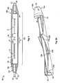
- Fig. 1shows a schematic sectional view of a splice protection device 1.
- the splice protection device 1is arranged between a wider cable 2 and a connector cable 3.
- the provider cable 2comprises a branching optical fiber 4; the connector cable 3 has a connecting optical fiber 5.
- the provider 2 and the connector cable 3are provided with tube-shaped cable jackets 6, 7.
- the branching optical fiber 4To make the branching optical fiber 4 accessible for mounting a splice with the connecting optical fiber 5, a portion of the cable jacket 6 at the end of the provider cable 2 has been removed. Correspondingly, also a portion of the connector cable jacket 7 at the end of the connector cable 3 has been removed. At an end portion 2a of the provider cable 2 the branching optical fiber 4 extends out of the cable jacket 6 and abuts the connecting optical fiber 5, which extends out of an end portion 3a of the connector cable 3. The abutting ends of the branching optical fiber 4 and the connecting optical fiber 5 are connected by a splice 8. The splice 8 is received by the tube 10, which forms a housing for the splice 8.
- the one or more branching optical fibers 4 and the one or more connecting optical fibers 5may be spliced together in any conventional manner, such as by fusion or mechanical splicing, either individually or en masse.
- the splice protection device 1comprises a first tube 9 and a second tube 10, the second tube 10 arranged concentrically and slidably in the first tube 9.
- an end 9a of the first tube 9may be moved into an end 6a of the cable jacket 6.
- the cable jacket 6 and the first tube 9may also be connected to each other by a forced closure e.g. by gluing or a shrink tube.
- An end 7a of the cable jacket 7 of the connector cable 3extends into the second tube 10 and can be connected to the second tube 10 by a form closure.
- the overlengthi.e. the length of the connecting optical fiber 5 projecting from the jacket 7 of the connector cable 3 and the length of the branching optical fiber 4 projecting from the jacket 6 of that cable are appropriately selected to effect splicing.
- the overlength of the branching optical fiber 4is introduced into the first tube 9 while the overlength of the connecting optical fiber 5 is introduced into the second tube 10.
- the first tube 9is pushed into the cable jacket 6 thereby exposing the entire overlength of the branching optical fiber 4.
- the second tube 10is telescopically slid over the cable jacket 7 thereby exposing the overlength of the connecting optical fiber 5.
- both tubes 9, 10are moved towards each other.
- the second tube 10is inserted into the first tube 9.
- the splice protection device 1replaces the function of the cable jackets 6, 7 at the splice 8 and where the cable jackets 6, 7 have been removed. It prevents damage by moisture or from pollution or bending the optical fibers 4, 5.
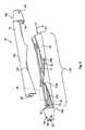
- Fig. 2shows a second embodiment of a part of the inventive splice protection device. Since most of the details illustrated therein are identical to the first embodiment, only the differences thereto will be described in more detail.
- the connector cable 3can be provided with a precast receive for the splice protection device 1.
- the cable jacket 7is, at an end portion 3a of the connector cable 3, provided with a stop 7b formed by an offset reducing the inner diameter of the cable jacket 7 at the end 7a.
- the first tube 9is provided with a corresponding stop 9b, the stop 9b extending in a radial direction and increasing the outer diameter of the end 9a of the first tube 9.
- the first tube 9has a second stop 9d which reduces the inner diameter of the first tube at the second end 9c.
- the second stop 9dis adapted to interfere with a stop 10c positioned at a second end 10b.
- the connector cable 3can be provided with inner stops 3b adapted to interfere with the stops 9b when the splice protection device 1 is moved into the cable jacket 7.
- Fig. 3 and 3ashow a third embodiment of the present invention, and the same reference numerals have been used.
- Fig. 3shows a fiber optic cable assembly provided with a protection device 1.
- a window cutis made in the cable jacket 6 to expose the fibers and fiber bundles enclosed therein.
- the window 11 a created by the removal of a portion of the cable jacket 6 or of the outer casing of the provider cable 2is the location of a tap off.
- a tap-off device 12is arranged at the branch point 11.
- the provider cable 2is received by a substantially channel shaped seating portion 12a of the tap-off device 12 (of Fig. 3a ).
- the seating portion 12ais provided by a shell 12b which circumferentially abuts against the cable jacket 6 of the provider cable 2.
- Those shells 12bare provided at the longitudinal ends of the tap-off device 12.
- the tap-off device 12has receiving groves 12c for receiving a cable binder partially surrounding the outer circumference of the shell 12b and partially surrounding the circumference of the cable jacket 6 thereby connecting the tap-off device 12 to the provider cable 2.
- the tap-off device 12provides a longitudinal recess 12d adapted to be aligned with the window 11 a of the cable jacket 6 and thus, exposing the optical fibers of the provider cable 2 at the branching point 11.
- the longitudinal directioni.e.
- this longitudinal recess 12dis terminated at each end by a bent section 12e, each of them providing a slight curvature forming a transition between a guiding face of the tap-off device 12 extending essentially parallel to the provider cable 2 and an end face of the longitudinal recess 12d extending oblique to this longitudinal direction, the latter surface terminating in a rounded rim 12f.
- the specific design of the bent section 12e and the rounded rim 12fis to assist pulling out performance for pulling of a selected branching optical fiber at the branching point 11 out of the provider cable 12.
- the tap-off device 12includes six fiber outlet ports 13a, 13b, 13c, 13d, 13,e, 13f for guiding branching optical fibers 4 out of the tap off device 12.
- the fiber outlet ports 13a-fare provided with a cone 14 with a stepped outer circumference providing holding rims 14a extending essentially in a radial direction of a channel 14b recessed in each fiber outlet port 13.
- the cone 14is recessed for its entire length over about 40 to 70° in the circumferential direction thereby providing a lateral recess 14c which allows radial insertion of a branching optical fiber 4 into the channel 14b.
- the splice protection deviceis provided with an adaptor sleeve 15 for connecting the splice protection device 1 to the fiber outlet port 13f and thus to the tap-off device 12.
- This adaptor sleeve 15is adapted to receive the cone 14 and is provided with counter surfaces for the securing rims 14a to provide a snapping connection, through which the protection device 1 is easily connected to the tap-off device 12 but which can be released in case of need.
- One end of the first tube 9ais connected to the adapter sleeve 15.
- the other end 9creceives the second tube 10 of smaller diameter.
- the second end 10b of this second tubeis secured to a housing part 16a which will be described hereinafter by referring to Figures 4 and 5 in further detail.
- Fig. 4is a schematic sectional view of the housing 16 constituting the splice holder 18.
- the housing 16encloses a chamber 17 for accommodating the splice 8.
- the housing 16is formed like a torpedo and tightly seals the splice 8.
- the chamber 17is surrounded by a fairly thin wall of a central section 16c with a cylindrical outer surface. This central section 16c circumferentially surrounds the splice 8.
- the housing 16furthermore has terminal sections 16d, 16e, each of them holding a tube.
- the terminal section 16dis connected to the second tube 10 while the terminal section 16e is connected with a further tube 21.
- the terminal sections 16d, 16eare each formed as truncated cones, the larger diameter thereof merging into the outer circumferential surface of the central section 16c while the smaller diameter end provides an opening 19 of a central tube duct 20 leading to the chamber 17 and being provided with an inner diameter slightly larger than the outer diameter of the assigned tube 10, 21.
- the terminal sections 16d, 16eprovide for an inner end face 24, 25 limiting the chamber 17 in the longitudinal direction of the tubes 10, 12 and providing an abutment for the splice 8 within said chamber.
- Fig. 5is an exploded view of a splice holder 18 and elucidates the composition of the housing 16 of two parts, i.e. the first part 16a and the second part 16b.
- the housing 16is made of elastically deformable material, for example, plastics. Both parts 16a, 16b are identical, such that the respective parts can be made in the same injection molding mold.
- each part 16a, 16bhas a semicircular core section 22.
- both core sections 22contact each other with a contacting surface 22a extending in the longitudinal direction of the housing 16 and in a plane containing the central axis of the cylindrical central section 16c.
- a partial cylindrical shell 23Over the entire length of the cylindrical central section 16c, a partial cylindrical shell 23, partially projects from and partially exposes said core section 22. This shell is a partial cylindrical shell 23 as it does not extend over the entire circumference of the housing 16.
- the partial cylindrical shell of the assigned part 16a, 16bhas an extension of less than 180°, while the extension is a portion where the partial cylindrical shell 23 projects from the core section 22, said cylindrical shell 23 extends over an angle of more than 180°.
- the smallest extension of the cylindrical shell 23is approximately 140° while the maximum extension is approximately 220°.
- Such a maximum extensionis provided by teeth-like projections 23a of the semi-cylindrical shell 23 being assigned to complementarily formed tooth-shaped recesses 23b exposing the core section 22 of the other of said parts 16a, 16b. Due to this specific design of each of the parts 16a, 16b, the same can be snapped against each other by connecting the two parts 16a, 16b in a radial direction.
- Both terminal sections 16d, 16e of the parts 16a, 16bhave radially extending openings 16f which are aligned towards the circumference the assigned tube 10, 21 for fixing the same by means of a screw or by inserting glue through those openings 16.
- the optical fiber which forms the branching optical fiber 4is introduced in a radial direction into the cones 14 through channel 14b.
- the fiberis then passed through the adaptor sleeve 15 and through the first and the second tubes 9, 10, the latter being preassembled with the assigned housing part 16b.
- the branching optical fiber 4passes through the second part 16b of the housing 16.
- the connecting optical fiber 5is passed through tubes telescopically arranged with respect to the further tube 21 and into the first part 16a of the housing 16.
- the telescopic arrangement of tubesis maximally reduced in the longitudinal extension of the respective fiber. Then, splicing is effected.
- Both parts 16a, 16b of the housingare positioned next to each other such that the connecting surfaces 22a of the core section 22 of both parts 16a, 16b are facing each other. Then, the two parts 16a, 16b are snapped securely to each other by snapping the tooth-like projections 23a into the tooth-shaped recesses 23b.
- the housing parts 16a, 16bmay be unreleasably connected e.g. by a tape, cable binders or a shrink sleeve.
- the overlength of fiber used for splicingis stored within the telescopic tubing.
- This telescopic tubingis of fairly soft material.
- the spliced overlengthmay be arranged in a loop also comprising the housing 16 and stored within a central shaft of a building in a compact and protected manner. It is even thinkable to insert parts of the splicing overlength including the housing into duct work for cable within a building as the housing 16 can be made fairly small in diameter and thus pass through such duct work.
- Fig. 7illustrates a schematical cross sectional view through a multi dwelling building having multiple dwelling units on each floor.
- the buildinghas a central rise shaft 27 through which an optical cable 2 is passed from a basement to the last floor.
- Figure 7also shows a terminal box 28 providing access to the rise shaft 27 on each floor adjacent to the optical cable 2 providing access to the rise shaft 27.
- Terminating in said terminal box 28is duct work 29 for a cable leading to an access point 30 provided within a single dwelling unit 31.
- the optical cable 2 passing through the rise shaft 27can be any conventionally known optical cable. However, it is preferred to use an optical cable 2 which is flexible and houses plural optical fibers in a rather dense manner within a jacket such that each optical fiber can be pulled out from the jacket after partially removing the jacket, e.g. in the vicinity of the terminal box 28.
- a preassembled optical cable depicted in Figure 8is used.
- This connecting optical fiber cableis identified with reference numeral 3 and is prepared as a preassembled cable having attached thereto a connector 32.
- the connector cable 3is a very flexible cable having an outer surface provided by an outer jacket 34 of polyamide. Surrounded by said outer jacket 34 is an aramidic strength member 35 (Kevlar TM ) which serves as a pull release insert within the connector cable 3.
- This strength member 35surrounds an inner jacket 36 of tight acrylate housing and surrounding the optical fiber 5.
- this optical cable 3is very flexible and slim and thus capable of being passed through duct work for a cable.
- the connector cable 3When connecting said connector cable 3 with the connector 32 to the central optical cable 2, the connector cable 3 is passed through the duct work 29 in the direction of arrow A. Passing can be achieved with a conventional pulling wire 37 used for dragging electrical wires through duct work 29. Accordingly, no splicing work is necessary within the dwelling unit 31. Instead, splicing is attained in the above described manner within the terminal box.
- the housing 16 with housing parts 16a, 16bis used, the connector cable 3 is passed through tube 21 and the branched off fiber 4 is prepared as previously shown with respective Figure 3 . After splicing, the telescopic tubing will be expanded and the housing parts 16a, 16b will be connected.
Landscapes
- Physics & Mathematics (AREA)
- General Physics & Mathematics (AREA)
- Optics & Photonics (AREA)
- Engineering & Computer Science (AREA)
- Plasma & Fusion (AREA)
- Light Guides In General And Applications Therefor (AREA)
- Mechanical Coupling Of Light Guides (AREA)
Description
- The present invention relates to a splice protection device with the features defined in claim 1, and a method, particularly for providing an access-point to a provider cable in a dwelling unit of a multi dwelling unit with the steps defined in
claim 11. - A generic splice protection device according to the preamble of claim 1 is e.g. known from
GB 2 192 732 A - Fiber optic cable is available in many physical variations. There are, for instance, single and multiple fiber constructions, aerial and direct burial cable types. Usually an outer jacket of PA, PVC or similar material is extruded over the cable to protect the inside of the cable from environmental impacts. The fibers can be protected by a loose fitting tube or a tight fitting buffer coating. In the loose tube method the fiber is enclosed in a plastic buffer-tube that is larger in inner diameter than the outer diameter of the fiber itself. Since the fiber is basically free to float within the tube, mechanical forces acting on the outside of the cable do not reach the fiber. For splicing fibers the protecting tubes and jackets must be removed to have direct access to the fibers. After connecting the fibers by a mechanical or fusion splice the fibers and the splice must be protected to prevent damage by environmental effects or external forces.
US 2007/0009214 A1 ,US 7,127,143 B2 ,US 7,277,614 B2 ,US 2006/0056782 A1 andUS 7,155,093 B2 disclose fiber optic cable assemblies comprising a fiber optic distribution cable having predetermined optical fibers terminated and branched at a cable access point and a tether cable optically connected to the predetermined optical fibers. The cable access point is encapsulated by a flexible over-molded body. To protect the components of said cable access point, an over-molding material blocking wrap or protective layer is added around the distribution or tether cable prior to over-molding.- For protecting the untreated portion of the optical fibers and to provide a guide channel for the optical fibers to the tether, the assemblies described in the
US 2007/0009214 A1 ,US 2006/0056782 A1 andUS 7,155,093 B2 have flexible tubings, routing the optical fibers of the tether, optically connected to the optical fibers of the distribution cable, out of the over-molded body. US 7,242,841 B2 discloses a flexible cross-connect apparatus for cross-connecting fiber optic cables. To provide for a preferential bending plane, the cross-connect apparatus includes a transition string member formed from a flexible material that is shaped so that it has a preferential bend characteristic. The fiber optic cable jackets are connected to the opposing ends of the transition string member by cable clamp assemblies.- To reduce furcation assemblies in price,
US 7,266,274 B2 andUS 2008/0019641 A1 disclose a pre-connectorized fiber optic distribution cable assembly which includes a mid-span access location along the length of a distribution cable. The mid-span access location, the accessed, terminated and connectorized optical fiber, the optical fiber and at least a portion of the receptacle are encapsulated by a protective over-molded shell. US 5,210,812 shows a housing for mounting at a branch point of a distribution cable for protecting the optical fibers and splices from damage. The housing forms an enclosure for the splices which are held in place mechanically by rows of pins.- Further housings for protecting optical fiber splices are described in
US 6,466,725 B2 andUS 6,619,697 B2 . The housings consist of two parts which are connected to each other by an integral hinge. The substantially Y-shaped housings consist of a main body for receiving a distribution cable and a branched portion for receiving the splice and one or several connecting cables. US 6,338,579 B1 discloses a fiber protection sleeve assembly suitable for reducing damage to optical fibers in a fiber optical cable caused by vibration or shock after assembly. Said fiber protection sleeve assembly comprises a first tube, a second tube and a third tube. The first tube is partially and slidably arranged in a capillary tube end of a capillary tube and has a bore for allowing optical fibers to pass through and for preventing contact between said capillary tube and the optical fibers respectively. The second tube frictionally engages the first tube for arranging the first tube in relation to the capillary tube end. Said second tube has a bore for allowing the optical fibers to pass through for splicing to another optical fiber. The third tube is provided for arranging and crimping to a carrier tube to abut the second tube against the capillary tube end. Said third tube has a bore for allowing the optical fibers to pass through. The optical fibers passing through the first to the third tubes are spliced outside said first to third tubes, which splices are covered by a heat-shrink tube.- Further, for instance, a method for providing an access-point to a provider cable in a dwelling unit of a multi dwelling unit is known from
EP 1 944 868 A1 . Said method comprises the steps of branching of at least one branching optical fiber of the provider cable at a branch portion adjacent to a dwelling unit. A pre-assembled connector cable provided with a connector is passed through a duct work for cable to the branch point and the branching optical fiber is spliced with the optical fiber of the connector cable. - Splice protection devices for protecting optical splices are, for example, used in multiple dwelling units which receive outside service provider cables from a provider. These outside service provider cables are coupled with cables feeding individual dwelling units within the multiple dwelling unit. The cables are typically housed within a riser shaft within the multiple dwelling unit. That shaft typically is a riser shaft, i.e. extends in a vertical direction and houses a number of services including the optical network intended to distribute signals to each individual dwelling unit within the multiple dwelling unit. Due to the high number of cables and tubes which are arranged within the riser shaft the space for mounting optical fiber splices within the riser shaft is mostly very small. Hence, connecting a connection cable to the provider cable and mounting splice protection devices for protecting the optical splices is made difficult. Further, electrical or plumbing installation may render this shaft a severe environment for optical cables.
- Hence, a problem to be solved is to provide a splice protection device for optical fiber splices which requires less space and which is easy to mount.
- Accordingly, in view of said prior art as mentioned above, it is an object of the present invention to provide a splice protection device for optical fiber splices which is easy to mount by maintaining a compact design and to provide a method, particularly for providing an access-point to a provider cable in a dwelling unit of a multi dwelling unit, wherein said splice protection device is used for protecting a splice between a branching optical fiber and the connecting optical fiber.
- The above object is solved by a splice protection having the features as specified in claim 1 and by a method as specified in
claim 11. - The inventive splice protection device comprises a first and a second tube, the second tube being arranged concentrically and slidably in the first tube.
- The splice protection device allows for adapting its length by telescopically moving its tubes. The splice protection device of the present invention is in particular useful for splicing individual optical fibers of an optical cable. For mechanical or fusion splicing, both optical fibers to be spliced have to be exposed, i.e. any jacket surrounding the optical fiber needs to be moved for a certain length of each of the fibers. Such overlength has to be covered and shielded from the environment after splicing. It is known in prior art to form a loop of this overlength and store the loop in a housing likewise receiving the splice. With the present invention, however, such bulky housing can be avoided. The entire overlength can be exposed by sliding the telescopic tubes into each other. After splicing, the tubes may be extended and form a protective cover for the overlength of a branching fiber and/or a connecting fiber.
- While it is preferred to use the inventive splice protection device for shielding single optical fibers which are to be spliced, such preferred use being best adaptable with a second tube, which forms the smaller opposed tube, having an inner diameter which is restricted to receive only one optical fiber, the tubes may have larger inner diameters to receive multiple fibers or even fibers whereby each or a plurality of them are surrounded by a jacket.
- For protecting a splice of two optical fibers, usually two sets of first and second tubes, both of said sets may comprise further tubes. At least one of said sets comprises a holder which is connected to one of the first or the second tube and is adapted to receive the spice. A splice according to the following description is to be understood as an element which surrounds both terminal ends of the two fibers to be spliced, such element may protect the terminal ends in case of fusion splicing (fusion splice) and/or effect the connection of both fibers by mechanically holding both fibers at the terminal ends (mechanical splice). Both of the splice protecting devices are mounted on the respective fibers, i.e. the fibers are passed through the first and the second tubes and the holder. The tubes of both splice protection devices are telescopically slid over each other, thereby exposing the overlength. After splicing the tubes of both splice protection devices are expanded and joined with each other at the splice, receiving the splice within a holder. This holder preferably is adapted to tightly surround the splice.
- The holder preferably surrounds the splice and connects with the at least one tube with a torpedo-like configuration adding only as much thickness in the radial direction to the splice as required for holding and covering the splice and to form a connection between the tubes of the two splice protection devices sufficiently reliably. In the subject configuration, the holder preferably has conical end faces for allowing e.g. introduction of the holder into duct work for cable. The holder which tightly surrounds the splice may allow some degree of movement of the splice within the holder. The holder will, however, form a form closure for the splice, i.e. constitute an abutment shape which will co-operate with the splice to hold the same within the splice holder. The play between the splice and the walls of the housing defining a chamber for receiving the splice may be a radial and/or an axial play. With those dimensional provisions, the two splice protection devices and the holder can be considered as a fairly tight jacket around the overlength of both fibers.
- According to the invention, the housing comprises a first part and a second part. Both parts can be connected to separate tubes. The second part is connected to the first or the second tube while the first part is connected to a further tube which will likewise be concentrically arranged and slidable with respect to a still further tube. The further tube and the still further tube may be identical with the first tube and the second tube, respectively. Both of the first part and the second part of the housing are in a pre-mounted position, in which those parts are not connected with each other, slidable with respect to each other in a fiber direction, i.e. in the direction of extension of the fibers to be connected. The first and the second part of the housing are preferably adapted to be directly connected with each other. The parts are preferably formed complementarily such that joining of both parts of the housing will lead to a closure for the splice, which closure is sufficiently rigid for a reliable connection of both parts with each other.
- Instead of tubes being connected to the splice holder on both of its ends, the same may only provide openings adapted to constitute a port. This port is such that a tube tightly surrounding the fiber can be connected to and/or passed into the housing of the splice holder.
- The first and the second parts of the housing are adapted to be connected to each other by form fit means, such form fit means holding the first and second part against each other in an interlocking manner. Preferably, both parts can be connected by simply snapping against each other. The first and second part of the housing in particular form a meshing configuration, the teeth thereof forming flanks extending in a direction perpendicular to the fiber direction and forming abutment faces of the two housing parts to lock the same against each other in this fiber direction. Preferably, in the mounted position, in which both parts are connected with each other and form the housing, those first and second parts are adapted to hold the splice by a form closure. The splice is not only received in a closure which allows not more than minimum radial movement of the splice within the housing, but also positions the splice in the fiber direction in a tight manner.
- Preferred embodiments of the splice protection device are defined in dependent claims.
- The inventive splice protection device is in particular suitable for use in a fiber optic cable assembly with a tap-off device having a seating portion for a provider cable and at least one fiber outlet port for a branching optical fiber. This tap-off device is used to be connected to the jacket of an optical cable usually comprising plural optical fibers, of which one is separated and branched off for providing access to the optical cable. The cable is secured to the tap-off device in the seating portion. The fiber optic cable assembly is adapted to be connected to a splice protection device of the invention. For this, the fiber optic cable assembly comprises an adaptor sleeve which is adapted to be plugged onto the fiber port and is connected to one of said first and second tubes while the other of said first and second tubes is connected to the splice holder. With such a fiber optical cable assembly, the branching optical fiber can easily be branched off from the cable and passed out of the tap-off device in a predetermined manner. The branching optical cable can then be fed through the first and second tubes which are connected to the tap-off device thereafter by plugging the connector sleeve onto the selected fiber outlet. The fiber outlet may preferably have a conical design while the connector sleeve has a conical opening facilitating alignment and positioning of the connector sleeve onto the outlet port. Both, the connector sleeve and the fiber outlet port preferably have cooperating snapping surfaces for proper connection of the two.
- In a preferred embodiment, the fiber outlet port has a cone with a ring segmented crosssection. With this preferred embodiment, the cone adapted to be inserted into the connector sleeve is not circumferentially closed. Thus, a channel provided within the outlet port is accessible in circumferential direction of the cone for inserting a branching optical fiber removed from the optical cable. Accordingly, the branching optical fiber can easily be pulled out from the jacket surrounding all optical fibers of the optical cable and inserted into the port by introduction into the channel in the radial direction thereof. This makes inser-tion of the entire overlength of the branching optical fiber in the axial direction of the channel dispensable. Further, the respective design facilitates the production of the tap-off device by plastic injection molding.
- To elongate the usable length of the splice protection device or to shorten the shortest possible length of the splice protection device, the splice protection device can comprise more than two tubes.
- To connect the protection device mechanically to the provider cable or to prevent dirt or moisture from entering the splice protection device, a tube arranged at an end of the splice protection device can be adapted to receive an end portion of the provider cable or to be received by the end portion of the provider cable. Correspondingly, a tube arranged at an end of the protecting device can be adapted to receive at least an end portion of the connector cable or to be received by the end portion of the connector cable.
- The splice protection device may be used for assembling splices in a multi dwelling unit within a cable shaft to build up a connecting to a provider cable. With a provider cable provided in a central supply shaft of a multiple dwelling unit, at least one branching optical fiber is branched off from this provider cable at a branch point of the provider cable. Therefore a branch point is chosen which is positioned adjacent to said dwelling unit. A connector cable for connecting a floor or a flat is passed through duct work for cable within the multi dwelling unit to the branch point. Aramid or Kevlar™ strands of the connector cable can be used to mechanically connect a tool, for example, a pulling wire, to pull the connector cable through duct work. Then, the free end of the connector cable is spliced with the branched off cable to provide access of the dwelling unit to the provider cable.
- Such a method may preferably be conducted with the splice protection device of the present invention. In such a case the connecting fiber of the connector cable is inserted into two tubes. One tube is slid telescopically into the other tube. After splicing the connecting fiber to the branching optical fiber the two tubes are extended telescopically, thereby protecting the overlength of one or both fibers.
- The invention will be described hereinafter in greater detail and in an exemplary manner using advantageous embodiments of the invention and with reference to the drawings. In the drawings:
- Fig. 1
- is a schematic view of a part of the inventive splice protection device;
- Fig. 2
- is a schematic sectional view of a second embodiment of a part of the inventive splice protection device;
- Fig. 3
- is a schematic perspective view of a third embodiment of the inventive splice protection device connected to a tap-off device;
- Fig. 3a
- is an enlarged view of the tap-off device shown in
Fig. 3 ; - Fig. 4
- is a schematic sectional view of an assembled splice holder of the embodiment shown in
Fig. 3 ; - Fig. 5
- is a schematic perspective view of a splice holder of
Fig. 4 ; - Fig. 5a
- is a schematic perspective view of a part of the splice holder of
Fig. 5 - Fig. 6
- is a perspective sectional view along the line VI-VI in
Fig. 5 ; - Fig. 7
- illustrates a cross-sectional view of a multi dwelling building cable;
- Fig. 8
- illustrates the composition of a single fiber optical cable.
- First of all, the construction of a part of the inventive splice protection device 1 configured according to the invention will be described with reference to
Fig. 1 , which shows a schematic sectional view of a splice protection device 1. - The splice protection device 1 is arranged between a
wider cable 2 and aconnector cable 3. Theprovider cable 2 comprises a branchingoptical fiber 4; theconnector cable 3 has a connectingoptical fiber 5. To protect theoptical fibers provider 2 and theconnector cable 3 are provided with tube-shapedcable jackets - To make the branching
optical fiber 4 accessible for mounting a splice with the connectingoptical fiber 5, a portion of thecable jacket 6 at the end of theprovider cable 2 has been removed. Correspondingly, also a portion of theconnector cable jacket 7 at the end of theconnector cable 3 has been removed. At anend portion 2a of theprovider cable 2 the branchingoptical fiber 4 extends out of thecable jacket 6 and abuts the connectingoptical fiber 5, which extends out of anend portion 3a of theconnector cable 3. The abutting ends of the branchingoptical fiber 4 and the connectingoptical fiber 5 are connected by asplice 8. Thesplice 8 is received by thetube 10, which forms a housing for thesplice 8. The one or more branchingoptical fibers 4 and the one or more connectingoptical fibers 5 may be spliced together in any conventional manner, such as by fusion or mechanical splicing, either individually or en masse. - The splice protection device 1 comprises a
first tube 9 and asecond tube 10, thesecond tube 10 arranged concentrically and slidably in thefirst tube 9. To fix thefirst tube 9 to theprovider cable 2, anend 9a of thefirst tube 9 may be moved into anend 6a of thecable jacket 6. Thecable jacket 6 and thefirst tube 9 may also be connected to each other by a forced closure e.g. by gluing or a shrink tube. Anend 7a of thecable jacket 7 of theconnector cable 3 extends into thesecond tube 10 and can be connected to thesecond tube 10 by a form closure. - In the embodiment of
Fig. 1 , the overlength, i.e. the length of the connectingoptical fiber 5 projecting from thejacket 7 of theconnector cable 3 and the length of the branchingoptical fiber 4 projecting from thejacket 6 of that cable are appropriately selected to effect splicing. Before splicing, the overlength of the branchingoptical fiber 4 is introduced into thefirst tube 9 while the overlength of the connectingoptical fiber 5 is introduced into thesecond tube 10. Thefirst tube 9 is pushed into thecable jacket 6 thereby exposing the entire overlength of the branchingoptical fiber 4. Thesecond tube 10 is telescopically slid over thecable jacket 7 thereby exposing the overlength of the connectingoptical fiber 5. After splicing, bothtubes second tube 10 is inserted into thefirst tube 9. - Thus, the splice protection device 1 replaces the function of the
cable jackets splice 8 and where thecable jackets optical fibers Fig. 2 shows a second embodiment of a part of the inventive splice protection device. Since most of the details illustrated therein are identical to the first embodiment, only the differences thereto will be described in more detail.- The
connector cable 3 can be provided with a precast receive for the splice protection device 1. To avoid loss of the splice protection device 1, thecable jacket 7 is, at anend portion 3a of theconnector cable 3, provided with astop 7b formed by an offset reducing the inner diameter of thecable jacket 7 at theend 7a. Thefirst tube 9 is provided with acorresponding stop 9b, thestop 9b extending in a radial direction and increasing the outer diameter of theend 9a of thefirst tube 9. At asecond end 9c of thefirst tube 9 opposite to theend 9b thefirst tube 9 has asecond stop 9d which reduces the inner diameter of the first tube at thesecond end 9c. Thesecond stop 9d is adapted to interfere with a stop 10c positioned at asecond end 10b. - To prevent the splice protection device 1 from moving too far into the
cable jacket 7, theconnector cable 3 can be provided withinner stops 3b adapted to interfere with thestops 9b when the splice protection device 1 is moved into thecable jacket 7. Fig. 3 and3a show a third embodiment of the present invention, and the same reference numerals have been used.Fig. 3 shows a fiber optic cable assembly provided with a protection device 1. At abranch point 11 of theprovider cable 2 a window cut is made in thecable jacket 6 to expose the fibers and fiber bundles enclosed therein. Thewindow 11 a created by the removal of a portion of thecable jacket 6 or of the outer casing of theprovider cable 2 is the location of a tap off. A tap-off device 12 is arranged at thebranch point 11. Theprovider cable 2 is received by a substantially channel shapedseating portion 12a of the tap-off device 12 (ofFig. 3a ).- The
seating portion 12a is provided by ashell 12b which circumferentially abuts against thecable jacket 6 of theprovider cable 2. Thoseshells 12b are provided at the longitudinal ends of the tap-off device 12. There, the tap-off device 12 has receiving groves 12c for receiving a cable binder partially surrounding the outer circumference of theshell 12b and partially surrounding the circumference of thecable jacket 6 thereby connecting the tap-off device 12 to theprovider cable 2. Between bothshells 12b, the tap-off device 12 provides alongitudinal recess 12d adapted to be aligned with thewindow 11 a of thecable jacket 6 and thus, exposing the optical fibers of theprovider cable 2 at the branchingpoint 11. In the longitudinal direction, i.e. the running direction of theprovider cable 2, thislongitudinal recess 12d is terminated at each end by abent section 12e, each of them providing a slight curvature forming a transition between a guiding face of the tap-off device 12 extending essentially parallel to theprovider cable 2 and an end face of thelongitudinal recess 12d extending oblique to this longitudinal direction, the latter surface terminating in arounded rim 12f. The specific design of thebent section 12e and therounded rim 12f is to assist pulling out performance for pulling of a selected branching optical fiber at the branchingpoint 11 out of theprovider cable 12. - The tap-
off device 12 includes sixfiber outlet ports optical fibers 4 out of the tap offdevice 12. Thefiber outlet ports 13a-f, are provided with acone 14 with a stepped outer circumference providingholding rims 14a extending essentially in a radial direction of achannel 14b recessed in each fiber outlet port 13. As evident fromFig. 3a , thecone 14 is recessed for its entire length over about 40 to 70° in the circumferential direction thereby providing a lateral recess 14c which allows radial insertion of a branchingoptical fiber 4 into thechannel 14b. - As evident from
Figure 3 , the splice protection device is provided with anadaptor sleeve 15 for connecting the splice protection device 1 to thefiber outlet port 13f and thus to the tap-off device 12. Thisadaptor sleeve 15 is adapted to receive thecone 14 and is provided with counter surfaces for the securingrims 14a to provide a snapping connection, through which the protection device 1 is easily connected to the tap-off device 12 but which can be released in case of need. One end of thefirst tube 9a is connected to theadapter sleeve 15. Theother end 9c receives thesecond tube 10 of smaller diameter. Thesecond end 10b of this second tube is secured to ahousing part 16a which will be described hereinafter by referring toFigures 4 and5 in further detail. Fig. 4 is a schematic sectional view of thehousing 16 constituting thesplice holder 18. Thehousing 16 encloses achamber 17 for accommodating thesplice 8. Thehousing 16 is formed like a torpedo and tightly seals thesplice 8. Thechamber 17 is surrounded by a fairly thin wall of a central section 16c with a cylindrical outer surface. This central section 16c circumferentially surrounds thesplice 8. Thehousing 16 furthermore hasterminal sections terminal section 16d is connected to thesecond tube 10 while theterminal section 16e is connected with afurther tube 21. Theterminal sections opening 19 of acentral tube duct 20 leading to thechamber 17 and being provided with an inner diameter slightly larger than the outer diameter of the assignedtube terminal sections inner end face chamber 17 in the longitudinal direction of thetubes splice 8 within said chamber.Fig. 5 is an exploded view of asplice holder 18 and elucidates the composition of thehousing 16 of two parts, i.e. thefirst part 16a and thesecond part 16b. Thehousing 16 is made of elastically deformable material, for example, plastics. Bothparts - In the central section 16c, each
part semicircular core section 22. In the assembled state (compareFig. 6 ) bothcore sections 22 contact each other with a contactingsurface 22a extending in the longitudinal direction of thehousing 16 and in a plane containing the central axis of the cylindrical central section 16c. Over the entire length of the cylindrical central section 16c, a partialcylindrical shell 23, partially projects from and partially exposes saidcore section 22. This shell is a partialcylindrical shell 23 as it does not extend over the entire circumference of thehousing 16. At locations where thecore section 22 is exposed, the partial cylindrical shell of the assignedpart cylindrical shell 23 projects from thecore section 22, saidcylindrical shell 23 extends over an angle of more than 180°. The smallest extension of thecylindrical shell 23 is approximately 140° while the maximum extension is approximately 220°. Such a maximum extension is provided by teeth-like projections 23a of thesemi-cylindrical shell 23 being assigned to complementarily formed tooth-shapedrecesses 23b exposing thecore section 22 of the other of saidparts parts parts housing parts projection 23a with the tooth-shapedrecesses 23b, both shapes being complementary to each other, there is an interlocking between the twoparts tubes - Both
terminal sections parts openings 16f which are aligned towards the circumference the assignedtube openings 16. - For assembling the splice protection device of
Figures 3 to 6 , the optical fiber which forms the branchingoptical fiber 4 is introduced in a radial direction into thecones 14 throughchannel 14b. The fiber is then passed through theadaptor sleeve 15 and through the first and thesecond tubes housing part 16b. As a result, the branchingoptical fiber 4 passes through thesecond part 16b of thehousing 16. In the same way, the connectingoptical fiber 5 is passed through tubes telescopically arranged with respect to thefurther tube 21 and into thefirst part 16a of thehousing 16. The telescopic arrangement of tubes is maximally reduced in the longitudinal extension of the respective fiber. Then, splicing is effected. Then, the telescopic arrangement of the respective tubes is expanded. Bothparts surfaces 22a of thecore section 22 of bothparts parts like projections 23a into the tooth-shapedrecesses 23b. After connecting the twoparts housing 16, thehousing parts - As a result, the overlength of fiber used for splicing is stored within the telescopic tubing. This telescopic tubing is of fairly soft material. Accordingly, the spliced overlength may be arranged in a loop also comprising the
housing 16 and stored within a central shaft of a building in a compact and protected manner. It is even thinkable to insert parts of the splicing overlength including the housing into duct work for cable within a building as thehousing 16 can be made fairly small in diameter and thus pass through such duct work. Fig. 7 illustrates a schematical cross sectional view through a multi dwelling building having multiple dwelling units on each floor. The building has acentral rise shaft 27 through which anoptical cable 2 is passed from a basement to the last floor.Figure 7 also shows aterminal box 28 providing access to therise shaft 27 on each floor adjacent to theoptical cable 2 providing access to therise shaft 27. Terminating in saidterminal box 28 isduct work 29 for a cable leading to anaccess point 30 provided within asingle dwelling unit 31. Theoptical cable 2 passing through therise shaft 27 can be any conventionally known optical cable. However, it is preferred to use anoptical cable 2 which is flexible and houses plural optical fibers in a rather dense manner within a jacket such that each optical fiber can be pulled out from the jacket after partially removing the jacket, e.g. in the vicinity of theterminal box 28.- When providing access to the
optical fiber cable 6 in a single dwelling unit within the multi dwelling unit, a preassembled optical cable depicted inFigure 8 is used. This connecting optical fiber cable is identified withreference numeral 3 and is prepared as a preassembled cable having attached thereto aconnector 32. Theconnector cable 3 is a very flexible cable having an outer surface provided by anouter jacket 34 of polyamide. Surrounded by saidouter jacket 34 is an aramidic strength member 35 (Kevlar™) which serves as a pull release insert within theconnector cable 3. Thisstrength member 35 surrounds aninner jacket 36 of tight acrylate housing and surrounding theoptical fiber 5. With an outer diameter of theouter jacket 34 of 750 µm, thisoptical cable 3 is very flexible and slim and thus capable of being passed through duct work for a cable. - When connecting said
connector cable 3 with theconnector 32 to the centraloptical cable 2, theconnector cable 3 is passed through theduct work 29 in the direction of arrow A. Passing can be achieved with a conventional pullingwire 37 used for dragging electrical wires throughduct work 29. Accordingly, no splicing work is necessary within thedwelling unit 31. Instead, splicing is attained in the above described manner within the terminal box. In particular, thehousing 16 withhousing parts connector cable 3 is passed throughtube 21 and the branched offfiber 4 is prepared as previously shown with respectiveFigure 3 . After splicing, the telescopic tubing will be expanded and thehousing parts - 1
- protection device
- 2
- provider cable
- 2a
- end portion (of 2)
- 3
- connector cable
- 3a
- end portion (of 3)
- 3b
- inner stop
- 4
- branching optical fibre
- 5
- connecting optical fibre
- 6
- cable jacket (of 2)
- 6a
- end (of 6)
- 7
- cable jacket (of 3)
- 7a
- end (of 7)
- 7b
- stop (of 7)
- 8
- splice
- 9
- first tube
- 9a
- end (of 9)
- 9b
- stop (of 9)
- 9c
- second end (of 9)
- 9d
- second stop (of 9)
- 10
- second tube
- 10a
- end (of 10)
- 10b
- second end (of 10)
- 10c
- stop (of 10)
- 11
- branch point
- 11a
- window
- 12
- tap-off device
- 12a
- seating portion
- 12b
- shell
- 12c
- receiving groove
- 12d
- longitudinal recess
- 12e
- bent section
- 12f
- rounded rim
- 13a-f
- fiber outlet ports
- 14
- cone
- 14a
- securing rim
- 14b
- channel
- 14c
- lateral recess
- 15
- adaptor sleeve
- 16
- housing
- 16a
- first part
- 16b
- second part
- 16c
- central section
- 16d
- terminal section
- 16e
- terminal section
- 16f
- openings
- 17
- chamber
- 18
- splice holder
- 19
- opening
- 20
- tube duct
- 21
- further tube
- 22
- core section
- 22a
- contacting surface
- 23
- cylindrical shell
- 23a
- tooth-like projection
- 23b
- tooth-like recess
- 24
- end faces (of 16a)
- 25
- end faces (of 16b)
- 27
- rise shaft
- 28
- terminal box
- 29
- duct work for cable
- 30
- access point
- 31
- dwelling unit
- 32
- connector
- 34
- outer jacket
- 35
- aramidic strength member/ aramid strand
- 36
- inner jacket
- 37
- pulling wire
- S
- fiber direction
- A
- insertion direction of
cable 3 inFig. 7
Claims (13)
- Splice projection device (1) for spliced optical fibers (4, 5), the splice protection device (1) comprising a first tube (9) and a second tube (10), the second tube (10) being arranged concentrically and slidably within the first tube (9), the first (9) and second tubes (10) being adapted to receive at least one spliced fiber (4, 5), being a branching optical fibre (4) spliced with a connecting optical fibre (5) by a splice (8),
characterized in that
the first or the second tube (9;10) is connected to a splice holder (18) comprising a housing (16), the housing (16) having a first and a second opening (19), the first opening (19) adapted to guide the branching optical fiber (4) into a central section (16c) of the housing (16), the second opening (19) adapted to guide the connecting optical fiber (5) out of said central section (16c) of the housing (16), and
the housing (16) comprises a first part (16a) being connected to a further tube (21) adapted to guide the connecting optical fiber (5), and a second part (16b) being connected to the first or the second tube (9; 1 0), wherein the first and second parts (16a, 16b) of the housing (16) form partial cylindrical shells (23) which form a continuous circumferential surface of the central section (16c) in their mounted position, and wherein the first part (16a) and the second part (16b) of the housing (16) are adapted to be connected to each other by form fit means (23a, 23b) holding the first part (16a) and the second part (16b) against each other in an interlocking manner. - Splice protection device (1) according to claim 1,characterized in that the splice holder (18) is adapted to tightly surround the splice (8) between the branching optical fiber (4) and the connecting optical fiber (5).
- Splice protection device (1) according to claims 1 or 2,characterized in that the connected first and second part (16a, 16b) of the housing (16) are adapted to hold the splice (8) by a form closure.
- Splice protection device (1) according to one of the claims 1 to 3,characterized in that the partial cylindrical shells (23) are complementary and arranged side by side in a direction normal to a fiber direction (S) of the at least one spliced fibre (4, 5) thereby surrounding a chamber (17) for the splice (8) and that the first and second part (16a, 16b) each have terminal sections (16d, 16e) of the housing (16), each of them providing a duct (20) for receiving one of the tubes (10; 21) and/or the optical fiber (4, 5).
- Splice protection device (1) according to one of the claims 1 to 4,characterized in that terminal sections in the form of a truncated cone (16d, 16e), which are adapted to receive one of the tubes (9, 10, 21) and provide an end face (24, 25) for abutment of the splice (8) received with the housing, project from each of the partial cylindrical shells (23) (16).
- Splice protection device (1) according to one of the claim claim 4 or claim 5 when dependent an claim 4,characterized in that the first and second parts (16a, 16b) of the housing (16) each form a core section (22), said core sections (22) being adapted to fit against each other thereby providing the chamber (17) for the splice (8) and fixed against each other by the form fit means (23a) which are effective to encompass the core sections (22) in a circumferential direction.
- Splice protection device (1) according to claim 6,characterized in that the core sections (22) of the first and second part s(16a, 16b) form an essentially continuous cylindrical core of the housing (16), andin that the partial cylindrical shell (23) of at least one part (16a) partially projects from the core section (22) of the at least one part (16a) while the partial cylindrical shell (23) of the other of said parts (16b) exposes the core section (22) of the other of said parts (16b) such that the partially cylindrical shell (23) of the at least one part (16a) snaps around the core section (22) of the other of said parts (16b) where the core section (22) of the other of said parts (16b) is exposed.
- Splice protection device (1) according to one of the claims 1 to 7,characterized in that the splice (8) forms outer circumferential holding sections and that the partial cylindrical shells (23) are adapted to snap around the holding sections.
- Splice protection device (1) according to one of the claims 1 to 8,characterized in that one of said tubes (9, 10) is connected to an adaptor sleeve (15)
- Fiber optic cable assembly, comprising: a splice protection device (1) according to claim 9, a tap-off device (12) having a seating portion (12a) for a provider cable (2) and a fiber outlet port (13a-f) for said branching optical fiber (4), wherein said adaptor sleeve (15) is adapted to be plugged onto the fiber outlet port (13a-f) and to be connected to one of said first or second tubes (9, 10), and wherein the other of said first or second tubes (9, 10) is connected to the splice holder (8).
- Method particularly for providing an access point to a provider cable (2) in a dwelling unit of a multi-dwelling unit comprising the following steps:branching off at least one branching optical fiber (4) of the provider cable (2) at a branch point (11) adjacent to said dwelling unit, passing a preassembled connector cable (3) being provided with a connector (32) through duct work (29) for cable to the branch point (11) and splicing the branching optical fiber (4) with an connecting optical fiber (5) of the connector cable (3),characterized in thatthe splice (8) between the branching optical fiber (4) and the connecting optical fiber (5) is protected by a protection device according to any of the claims 1 to 9, that the branching optical fiber (4) is arranged within the two tubes (9, 10), wherein one tube (9; 10) is telescopically slid into the other tube (9; 10) and that the two tubes (9, 10) are extended after splicing for protecting the branching optical fiber (4).
- Method according to claim 11,characterized in that said preassembled connector cable (3) is pulled through said duct work for cable from the branch point (11) of the dwelling unit to a position within a shaft.
- Method according to claim 11 or 12,characterized in that said preassembled connector cable (3) is provided with a pull relief insert being surrounded by a jacket of hardened polyamide.
Priority Applications (4)
| Application Number | Priority Date | Filing Date | Title |
|---|---|---|---|
| EP09001854.0AEP2216662B1 (en) | 2009-02-10 | 2009-02-10 | Splice protection device for optical splices and optical fibre cable assembly incorporating same |
| ES09001854TES2435424T3 (en) | 2009-02-10 | 2009-02-10 | Splicing protection device for optical splices and fiber optic cable assembly that incorporates it |
| CN201010128142.8ACN101799574B (en) | 2009-02-10 | 2010-02-08 | Splice protection device for optical splices |
| US12/658,572US8814446B2 (en) | 2009-02-10 | 2010-02-09 | Splice protection device for optical splices |
Applications Claiming Priority (1)
| Application Number | Priority Date | Filing Date | Title |
|---|---|---|---|
| EP09001854.0AEP2216662B1 (en) | 2009-02-10 | 2009-02-10 | Splice protection device for optical splices and optical fibre cable assembly incorporating same |
Publications (2)
| Publication Number | Publication Date |
|---|---|
| EP2216662A1 EP2216662A1 (en) | 2010-08-11 |
| EP2216662B1true EP2216662B1 (en) | 2013-09-18 |
Family
ID=40757062
Family Applications (1)
| Application Number | Title | Priority Date | Filing Date |
|---|---|---|---|
| EP09001854.0AActiveEP2216662B1 (en) | 2009-02-10 | 2009-02-10 | Splice protection device for optical splices and optical fibre cable assembly incorporating same |
Country Status (4)
| Country | Link |
|---|---|
| US (1) | US8814446B2 (en) |
| EP (1) | EP2216662B1 (en) |
| CN (1) | CN101799574B (en) |
| ES (1) | ES2435424T3 (en) |
Families Citing this family (16)
| Publication number | Priority date | Publication date | Assignee | Title |
|---|---|---|---|---|
| FR2964754B1 (en)* | 2010-09-13 | 2013-05-17 | Acome Soc Cooperative De Production Sa A Capital Variable | DEVICE FOR PROTECTING A SPLICE AND METHOD FOR INSTALLING SUCH A DEVICE |
| CN101968561A (en)* | 2010-10-22 | 2011-02-09 | 华为技术有限公司 | Prefabricated optical distribution cable and manufacturing method thereof |
| FR2967263B1 (en)* | 2010-11-05 | 2013-08-16 | Acome Soc Cooperative De Production Sa A Capital Variable | OPTICAL MODULES DERIVATION HOUSING |
| IT1402878B1 (en) | 2010-11-19 | 2013-09-27 | Prysmian Spa | OPTICAL TRANSITION BOX |
| IT1403284B1 (en)* | 2010-12-23 | 2013-10-17 | Prysmian Spa | OPTICAL DIRECTION DEVICE |
| CN102749691A (en)* | 2012-07-19 | 2012-10-24 | 江苏省电力设计院 | Connecting device for multi-fiber prefabricated outdoor optical cables of intelligent transformer substations |
| CN104597568A (en)* | 2013-11-01 | 2015-05-06 | 镇江红宝利电子有限公司 | Manufacturing method of optical fiber splice |
| US9465182B2 (en)* | 2014-06-30 | 2016-10-11 | Verizon Patent And Licensing Inc. | Fiber optic cable assembly with micro-duct protection |
| DK3221730T3 (en)* | 2014-11-20 | 2020-11-23 | Prysmian Spa | Device for connecting an optical cable and a protective tube |
| CN105891971A (en)* | 2016-06-18 | 2016-08-24 | 苏州高精特专信息科技有限公司 | Simple-structure type fiber connector |
| AU2017315132B2 (en)* | 2016-08-26 | 2022-09-08 | CommScope Connectivity Belgium BVBA | Light weight fiber optic splice and fiber management system |
| GB201701997D0 (en)* | 2017-02-07 | 2017-03-22 | Emtelle Uk Ltd | Improved pre-connectorised optical fibre construction |
| CA3166361A1 (en)* | 2020-01-29 | 2021-08-05 | Terry Lee Cooke | Preconnectorized distribution cable assemblies and methods of making using a pull string |
| US11886029B2 (en) | 2021-03-10 | 2024-01-30 | Afl Telecommunications Llc | Systems and methods of managing cables in telecommunication systems |
| EP4419957A4 (en)* | 2021-10-18 | 2025-07-30 | Commscope Technologies Llc | TELECOMMUNICATIONS CABLE SPLICE ARRANGEMENT PROTECTION SYSTEM |
| JP2023082975A (en)* | 2021-12-03 | 2023-06-15 | 住友電気工業株式会社 | Optical fiber cable and case for optical fiber cable |
Family Cites Families (25)
| Publication number | Priority date | Publication date | Assignee | Title |
|---|---|---|---|---|
| US4648168A (en)* | 1983-12-19 | 1987-03-10 | N.V. Raychem S.A. | Optical fibre breakout |
| GB2192732A (en) | 1983-12-19 | 1988-01-20 | Raychem Sa Nv | Insertion tool for optical fibres |
| US4978194A (en)* | 1989-08-28 | 1990-12-18 | Raynet Corporation | Stepped cable block |
| US5210812A (en) | 1991-04-05 | 1993-05-11 | Alcatel Na Cable Systems, Inc. | Optical fiber cable having spliced fiber branch and method of making the same |
| US5121458A (en)* | 1991-04-05 | 1992-06-09 | Alcatel Na Cable Systems, Inc. | Preterminated fiber optic cable |
| US5185840A (en)* | 1991-05-06 | 1993-02-09 | Computer Crafts, Inc. | Branching method for a multi-fiber fiberoptic cable |
| US5224189A (en)* | 1992-01-02 | 1993-06-29 | Litton Systems, Inc. | High pressure fiber optic splice and method of fabrication |
| US5684911A (en)* | 1995-09-01 | 1997-11-04 | Lucent Technologies Inc. | Sub-surface fiber optic splice housing and method of splicing fiber optic cable |
| US6338579B1 (en) | 2000-02-03 | 2002-01-15 | Robert F. Winiarski | Fiber optic sleeve assembly for use at a splice junction of a fiber optic cable |
| US6466725B2 (en) | 2000-11-29 | 2002-10-15 | Corning Cable Systems Llc | Apparatus and method for splitting optical fibers |
| US6619697B2 (en) | 2000-12-27 | 2003-09-16 | Nkf Kabel B.V. | Y-branch splittable connector |
| US7450804B2 (en) | 2004-05-24 | 2008-11-11 | Corning Cable Systems Llc | Distribution cable assembly having overmolded mid-span access location |
| US7330621B2 (en) | 2004-05-24 | 2008-02-12 | Corning Cable Systems Llc | Flexible optical closure and other flexible optical assemblies |
| US7127143B2 (en)* | 2004-05-24 | 2006-10-24 | Corning Cable Systems Llc | Distribution cable assembly having overmolded mid-span access location |
| US7155093B2 (en) | 2004-05-24 | 2006-12-26 | Corning Cable Systems Llc | Distribution cable having overmolded mid-span access location with preferential bending |
| US7266274B2 (en) | 2004-11-03 | 2007-09-04 | Corning Cable Systems Llc | Pre-connectorized fiber optic distribution cable having overmolded access location |
| US7277614B2 (en) | 2004-12-03 | 2007-10-02 | Corning Cable Systems Llc | Tether assembly having individual connector ports |
| US7242841B2 (en) | 2005-02-28 | 2007-07-10 | Corning Cable Systems, Llc | Cross-connect fiber optic cables and associated cross-connect sections |
| WO2006113810A2 (en)* | 2005-04-19 | 2006-10-26 | Adc Telecommunications, Inc. | Fiber breakout with integral connector |
| JP4767634B2 (en) | 2005-09-13 | 2011-09-07 | 株式会社沖データ | Light emitting integrated circuit, optical head, and image forming apparatus using the same |
| US7756372B2 (en)* | 2006-02-22 | 2010-07-13 | Tyco Electronics Corporation | Fiber optic cable systems and kits and methods for terminating the same |
| US7546018B2 (en)* | 2007-01-13 | 2009-06-09 | Ofs Fitel, Llc | Fiber optic cabling for multi-dwelling unit (MDU) and commercial building deployments |
| US8573855B2 (en)* | 2008-10-06 | 2013-11-05 | Adc Telecommunications, Inc. | Fanout cable assembly and method |
| EP2237090A1 (en)* | 2009-04-03 | 2010-10-06 | Tyco Electronics Raychem BVBA | Method for splicing an optical fiber element |
| US8885998B2 (en)* | 2010-12-09 | 2014-11-11 | Adc Telecommunications, Inc. | Splice enclosure arrangement for fiber optic cables |
- 2009
- 2009-02-10EPEP09001854.0Apatent/EP2216662B1/enactiveActive
- 2009-02-10ESES09001854Tpatent/ES2435424T3/enactiveActive
- 2010
- 2010-02-08CNCN201010128142.8Apatent/CN101799574B/ennot_activeExpired - Fee Related
- 2010-02-09USUS12/658,572patent/US8814446B2/enactiveActive
Also Published As
| Publication number | Publication date |
|---|---|
| EP2216662A1 (en) | 2010-08-11 |
| US20100232752A1 (en) | 2010-09-16 |
| CN101799574A (en) | 2010-08-11 |
| ES2435424T3 (en) | 2013-12-19 |
| CN101799574B (en) | 2015-07-08 |
| US8814446B2 (en) | 2014-08-26 |
Similar Documents
| Publication | Publication Date | Title |
|---|---|---|
| EP2216662B1 (en) | Splice protection device for optical splices and optical fibre cable assembly incorporating same | |
| CN100510818C (en) | Overmolded multi-port optical connection terminal with features to accommodate excess fiber length | |
| CN100578274C (en) | Pre-connected fiber optic distribution cables with overmolded entry sites | |
| US9798085B2 (en) | Splice enclosure arrangement for fiber optic cables | |
| JP4733115B2 (en) | Wiring cable assembly with composite molded intermediate branch point | |
| US8043013B2 (en) | Spliced-on connector system and method, splicer, and connector holder for producing the same | |
| US7740409B2 (en) | Multi-port optical connection terminal | |
| US20050111800A1 (en) | Pre-connectorized fiber optic distribution cable having multifiber connector | |
| JP2008501153A (en) | Adjustable tether assembly for fiber optic distribution cables | |
| EP2244115A1 (en) | Furcation bodies and fiber optic assemblies using the same | |
| EP3743756B1 (en) | Epoxy transitions for optical fiber modules | |
| EP2255235B1 (en) | Method of attachment of a connector to a fiber optic cable | |
| US20060067636A1 (en) | Connector and splice holder device | |
| US20250298213A1 (en) | Fiber optic system incorporating a duct-deployable multi-fiber ferrule | |
| AU2011203294B2 (en) | A tap point for connecting fiber optic cable |
Legal Events
| Date | Code | Title | Description |
|---|---|---|---|
| PUAI | Public reference made under article 153(3) epc to a published international application that has entered the european phase | Free format text:ORIGINAL CODE: 0009012 | |
| AK | Designated contracting states | Kind code of ref document:A1 Designated state(s):AT BE BG CH CY CZ DE DK EE ES FI FR GB GR HR HU IE IS IT LI LT LU LV MC MK MT NL NO PL PT RO SE SI SK TR | |
| AX | Request for extension of the european patent | Extension state:AL BA RS | |
| 17P | Request for examination filed | Effective date:20110211 | |
| 17Q | First examination report despatched | Effective date:20110310 | |
| AKX | Designation fees paid | Designated state(s):AT BE BG CH CY CZ DE DK EE ES FI FR GB GR HR HU IE IS IT LI LT LU LV MC MK MT NL NO PL PT RO SE SI SK TR | |
| GRAP | Despatch of communication of intention to grant a patent | Free format text:ORIGINAL CODE: EPIDOSNIGR1 | |
| GRAP | Despatch of communication of intention to grant a patent | Free format text:ORIGINAL CODE: EPIDOSNIGR1 | |
| INTG | Intention to grant announced | Effective date:20130409 | |
| GRAS | Grant fee paid | Free format text:ORIGINAL CODE: EPIDOSNIGR3 | |
| GRAA | (expected) grant | Free format text:ORIGINAL CODE: 0009210 | |
| AK | Designated contracting states | Kind code of ref document:B1 Designated state(s):AT BE BG CH CY CZ DE DK EE ES FI FR GB GR HR HU IE IS IT LI LT LU LV MC MK MT NL NO PL PT RO SE SI SK TR | |
| REG | Reference to a national code | Ref country code:GB Ref legal event code:FG4D | |
| REG | Reference to a national code | Ref country code:CH Ref legal event code:EP | |
| REG | Reference to a national code | Ref country code:IE Ref legal event code:FG4D | |
| REG | Reference to a national code | Ref country code:AT Ref legal event code:REF Ref document number:633065 Country of ref document:AT Kind code of ref document:T Effective date:20131015 | |
| REG | Reference to a national code | Ref country code:DE Ref legal event code:R096 Ref document number:602009018822 Country of ref document:DE Effective date:20131114 | |
| REG | Reference to a national code | Ref country code:ES Ref legal event code:FG2A Ref document number:2435424 Country of ref document:ES Kind code of ref document:T3 Effective date:20131219 | |
| PG25 | Lapsed in a contracting state [announced via postgrant information from national office to epo] | Ref country code:CY Free format text:LAPSE BECAUSE OF FAILURE TO SUBMIT A TRANSLATION OF THE DESCRIPTION OR TO PAY THE FEE WITHIN THE PRESCRIBED TIME-LIMIT Effective date:20130904 Ref country code:HR Free format text:LAPSE BECAUSE OF FAILURE TO SUBMIT A TRANSLATION OF THE DESCRIPTION OR TO PAY THE FEE WITHIN THE PRESCRIBED TIME-LIMIT Effective date:20130918 Ref country code:NO Free format text:LAPSE BECAUSE OF FAILURE TO SUBMIT A TRANSLATION OF THE DESCRIPTION OR TO PAY THE FEE WITHIN THE PRESCRIBED TIME-LIMIT Effective date:20131218 Ref country code:LT Free format text:LAPSE BECAUSE OF FAILURE TO SUBMIT A TRANSLATION OF THE DESCRIPTION OR TO PAY THE FEE WITHIN THE PRESCRIBED TIME-LIMIT Effective date:20130918 Ref country code:SE Free format text:LAPSE BECAUSE OF FAILURE TO SUBMIT A TRANSLATION OF THE DESCRIPTION OR TO PAY THE FEE WITHIN THE PRESCRIBED TIME-LIMIT Effective date:20130918 | |
| REG | Reference to a national code | Ref country code:NL Ref legal event code:VDEP Effective date:20130918 | |
| REG | Reference to a national code | Ref country code:AT Ref legal event code:MK05 Ref document number:633065 Country of ref document:AT Kind code of ref document:T Effective date:20130918 | |
| REG | Reference to a national code | Ref country code:LT Ref legal event code:MG4D | |
| PG25 | Lapsed in a contracting state [announced via postgrant information from national office to epo] | Ref country code:GR Free format text:LAPSE BECAUSE OF FAILURE TO SUBMIT A TRANSLATION OF THE DESCRIPTION OR TO PAY THE FEE WITHIN THE PRESCRIBED TIME-LIMIT Effective date:20131219 Ref country code:SI Free format text:LAPSE BECAUSE OF FAILURE TO SUBMIT A TRANSLATION OF THE DESCRIPTION OR TO PAY THE FEE WITHIN THE PRESCRIBED TIME-LIMIT Effective date:20130918 Ref country code:LV Free format text:LAPSE BECAUSE OF FAILURE TO SUBMIT A TRANSLATION OF THE DESCRIPTION OR TO PAY THE FEE WITHIN THE PRESCRIBED TIME-LIMIT Effective date:20130918 Ref country code:FI Free format text:LAPSE BECAUSE OF FAILURE TO SUBMIT A TRANSLATION OF THE DESCRIPTION OR TO PAY THE FEE WITHIN THE PRESCRIBED TIME-LIMIT Effective date:20130918 | |
| PG25 | Lapsed in a contracting state [announced via postgrant information from national office to epo] | Ref country code:CY Free format text:LAPSE BECAUSE OF FAILURE TO SUBMIT A TRANSLATION OF THE DESCRIPTION OR TO PAY THE FEE WITHIN THE PRESCRIBED TIME-LIMIT Effective date:20130918 Ref country code:BE Free format text:LAPSE BECAUSE OF FAILURE TO SUBMIT A TRANSLATION OF THE DESCRIPTION OR TO PAY THE FEE WITHIN THE PRESCRIBED TIME-LIMIT Effective date:20130918 | |
| PG25 | Lapsed in a contracting state [announced via postgrant information from national office to epo] | Ref country code:EE Free format text:LAPSE BECAUSE OF FAILURE TO SUBMIT A TRANSLATION OF THE DESCRIPTION OR TO PAY THE FEE WITHIN THE PRESCRIBED TIME-LIMIT Effective date:20130918 Ref country code:IS Free format text:LAPSE BECAUSE OF FAILURE TO SUBMIT A TRANSLATION OF THE DESCRIPTION OR TO PAY THE FEE WITHIN THE PRESCRIBED TIME-LIMIT Effective date:20140118 Ref country code:SK Free format text:LAPSE BECAUSE OF FAILURE TO SUBMIT A TRANSLATION OF THE DESCRIPTION OR TO PAY THE FEE WITHIN THE PRESCRIBED TIME-LIMIT Effective date:20130918 Ref country code:RO Free format text:LAPSE BECAUSE OF FAILURE TO SUBMIT A TRANSLATION OF THE DESCRIPTION OR TO PAY THE FEE WITHIN THE PRESCRIBED TIME-LIMIT Effective date:20130918 Ref country code:NL Free format text:LAPSE BECAUSE OF FAILURE TO SUBMIT A TRANSLATION OF THE DESCRIPTION OR TO PAY THE FEE WITHIN THE PRESCRIBED TIME-LIMIT Effective date:20130918 Ref country code:CZ Free format text:LAPSE BECAUSE OF FAILURE TO SUBMIT A TRANSLATION OF THE DESCRIPTION OR TO PAY THE FEE WITHIN THE PRESCRIBED TIME-LIMIT Effective date:20130918 | |
| PG25 | Lapsed in a contracting state [announced via postgrant information from national office to epo] | Ref country code:AT Free format text:LAPSE BECAUSE OF FAILURE TO SUBMIT A TRANSLATION OF THE DESCRIPTION OR TO PAY THE FEE WITHIN THE PRESCRIBED TIME-LIMIT Effective date:20130918 Ref country code:PL Free format text:LAPSE BECAUSE OF FAILURE TO SUBMIT A TRANSLATION OF THE DESCRIPTION OR TO PAY THE FEE WITHIN THE PRESCRIBED TIME-LIMIT Effective date:20130918 | |
| REG | Reference to a national code | Ref country code:DE Ref legal event code:R097 Ref document number:602009018822 Country of ref document:DE | |
| PG25 | Lapsed in a contracting state [announced via postgrant information from national office to epo] | Ref country code:PT Free format text:LAPSE BECAUSE OF FAILURE TO SUBMIT A TRANSLATION OF THE DESCRIPTION OR TO PAY THE FEE WITHIN THE PRESCRIBED TIME-LIMIT Effective date:20140120 | |
| PLBE | No opposition filed within time limit | Free format text:ORIGINAL CODE: 0009261 | |
| STAA | Information on the status of an ep patent application or granted ep patent | Free format text:STATUS: NO OPPOSITION FILED WITHIN TIME LIMIT | |
| 26N | No opposition filed | Effective date:20140619 | |
| PG25 | Lapsed in a contracting state [announced via postgrant information from national office to epo] | Ref country code:DK Free format text:LAPSE BECAUSE OF FAILURE TO SUBMIT A TRANSLATION OF THE DESCRIPTION OR TO PAY THE FEE WITHIN THE PRESCRIBED TIME-LIMIT Effective date:20130918 Ref country code:MC Free format text:LAPSE BECAUSE OF FAILURE TO SUBMIT A TRANSLATION OF THE DESCRIPTION OR TO PAY THE FEE WITHIN THE PRESCRIBED TIME-LIMIT Effective date:20130918 Ref country code:LU Free format text:LAPSE BECAUSE OF FAILURE TO SUBMIT A TRANSLATION OF THE DESCRIPTION OR TO PAY THE FEE WITHIN THE PRESCRIBED TIME-LIMIT Effective date:20140210 | |
| REG | Reference to a national code | Ref country code:CH Ref legal event code:PL | |
| REG | Reference to a national code | Ref country code:DE Ref legal event code:R097 Ref document number:602009018822 Country of ref document:DE Effective date:20140619 | |
| PG25 | Lapsed in a contracting state [announced via postgrant information from national office to epo] | Ref country code:CH Free format text:LAPSE BECAUSE OF NON-PAYMENT OF DUE FEES Effective date:20140228 Ref country code:LI Free format text:LAPSE BECAUSE OF NON-PAYMENT OF DUE FEES Effective date:20140228 | |
| REG | Reference to a national code | Ref country code:IE Ref legal event code:MM4A | |
| PG25 | Lapsed in a contracting state [announced via postgrant information from national office to epo] | Ref country code:IE Free format text:LAPSE BECAUSE OF NON-PAYMENT OF DUE FEES Effective date:20140210 | |
| REG | Reference to a national code | Ref country code:FR Ref legal event code:PLFP Year of fee payment:8 | |
| PG25 | Lapsed in a contracting state [announced via postgrant information from national office to epo] | Ref country code:MT Free format text:LAPSE BECAUSE OF FAILURE TO SUBMIT A TRANSLATION OF THE DESCRIPTION OR TO PAY THE FEE WITHIN THE PRESCRIBED TIME-LIMIT Effective date:20130918 | |
| PG25 | Lapsed in a contracting state [announced via postgrant information from national office to epo] | Ref country code:BG Free format text:LAPSE BECAUSE OF FAILURE TO SUBMIT A TRANSLATION OF THE DESCRIPTION OR TO PAY THE FEE WITHIN THE PRESCRIBED TIME-LIMIT Effective date:20130918 | |
| PG25 | Lapsed in a contracting state [announced via postgrant information from national office to epo] | Ref country code:HU Free format text:LAPSE BECAUSE OF FAILURE TO SUBMIT A TRANSLATION OF THE DESCRIPTION OR TO PAY THE FEE WITHIN THE PRESCRIBED TIME-LIMIT; INVALID AB INITIO Effective date:20090210 Ref country code:TR Free format text:LAPSE BECAUSE OF FAILURE TO SUBMIT A TRANSLATION OF THE DESCRIPTION OR TO PAY THE FEE WITHIN THE PRESCRIBED TIME-LIMIT Effective date:20130918 | |
| REG | Reference to a national code | Ref country code:FR Ref legal event code:PLFP Year of fee payment:9 | |
| PGFP | Annual fee paid to national office [announced via postgrant information from national office to epo] | Ref country code:FR Payment date:20170223 Year of fee payment:9 | |
| PGFP | Annual fee paid to national office [announced via postgrant information from national office to epo] | Ref country code:ES Payment date:20170227 Year of fee payment:9 | |
| PG25 | Lapsed in a contracting state [announced via postgrant information from national office to epo] | Ref country code:MK Free format text:LAPSE BECAUSE OF FAILURE TO SUBMIT A TRANSLATION OF THE DESCRIPTION OR TO PAY THE FEE WITHIN THE PRESCRIBED TIME-LIMIT Effective date:20130918 | |
| REG | Reference to a national code | Ref country code:FR Ref legal event code:ST Effective date:20181031 | |
| PG25 | Lapsed in a contracting state [announced via postgrant information from national office to epo] | Ref country code:FR Free format text:LAPSE BECAUSE OF NON-PAYMENT OF DUE FEES Effective date:20180228 | |
| REG | Reference to a national code | Ref country code:ES Ref legal event code:FD2A Effective date:20190801 | |
| PG25 | Lapsed in a contracting state [announced via postgrant information from national office to epo] | Ref country code:ES Free format text:LAPSE BECAUSE OF NON-PAYMENT OF DUE FEES Effective date:20180211 | |
| P01 | Opt-out of the competence of the unified patent court (upc) registered | Effective date:20230530 | |
| PGFP | Annual fee paid to national office [announced via postgrant information from national office to epo] | Ref country code:DE Payment date:20250227 Year of fee payment:17 | |
| PGFP | Annual fee paid to national office [announced via postgrant information from national office to epo] | Ref country code:IT Payment date:20250220 Year of fee payment:17 Ref country code:GB Payment date:20250227 Year of fee payment:17 |