EP2213247A1 - Tissue puncture closure device with automatic tamping - Google Patents
Tissue puncture closure device with automatic tampingDownload PDFInfo
- Publication number
- EP2213247A1 EP2213247A1EP10157302AEP10157302AEP2213247A1EP 2213247 A1EP2213247 A1EP 2213247A1EP 10157302 AEP10157302 AEP 10157302AEP 10157302 AEP10157302 AEP 10157302AEP 2213247 A1EP2213247 A1EP 2213247A1
- Authority
- EP
- European Patent Office
- Prior art keywords
- handle
- tamping
- gear
- assembly
- sealing plug
- Prior art date
- Legal status (The legal status is an assumption and is not a legal conclusion. Google has not performed a legal analysis and makes no representation as to the accuracy of the status listed.)
- Granted
Links
Images


Classifications
- A—HUMAN NECESSITIES
- A61—MEDICAL OR VETERINARY SCIENCE; HYGIENE
- A61B—DIAGNOSIS; SURGERY; IDENTIFICATION
- A61B17/00—Surgical instruments, devices or methods
- A61B17/0057—Implements for plugging an opening in the wall of a hollow or tubular organ, e.g. for sealing a vessel puncture or closing a cardiac septal defect
- A—HUMAN NECESSITIES
- A61—MEDICAL OR VETERINARY SCIENCE; HYGIENE
- A61B—DIAGNOSIS; SURGERY; IDENTIFICATION
- A61B17/00—Surgical instruments, devices or methods
- A61B2017/00367—Details of actuation of instruments, e.g. relations between pushing buttons, or the like, and activation of the tool, working tip, or the like
- A—HUMAN NECESSITIES
- A61—MEDICAL OR VETERINARY SCIENCE; HYGIENE
- A61B—DIAGNOSIS; SURGERY; IDENTIFICATION
- A61B17/00—Surgical instruments, devices or methods
- A61B17/0057—Implements for plugging an opening in the wall of a hollow or tubular organ, e.g. for sealing a vessel puncture or closing a cardiac septal defect
- A61B2017/00637—Implements for plugging an opening in the wall of a hollow or tubular organ, e.g. for sealing a vessel puncture or closing a cardiac septal defect for sealing trocar wounds through abdominal wall
- A—HUMAN NECESSITIES
- A61—MEDICAL OR VETERINARY SCIENCE; HYGIENE
- A61B—DIAGNOSIS; SURGERY; IDENTIFICATION
- A61B17/00—Surgical instruments, devices or methods
- A61B17/0057—Implements for plugging an opening in the wall of a hollow or tubular organ, e.g. for sealing a vessel puncture or closing a cardiac septal defect
- A61B2017/00646—Type of implements
- A61B2017/00654—Type of implements entirely comprised between the two sides of the opening
- A—HUMAN NECESSITIES
- A61—MEDICAL OR VETERINARY SCIENCE; HYGIENE
- A61B—DIAGNOSIS; SURGERY; IDENTIFICATION
- A61B17/00—Surgical instruments, devices or methods
- A61B17/0057—Implements for plugging an opening in the wall of a hollow or tubular organ, e.g. for sealing a vessel puncture or closing a cardiac septal defect
- A61B2017/00646—Type of implements
- A61B2017/00659—Type of implements located only on one side of the opening
Definitions
- This inventionrelates generally to medical devices and more particularly to devices for sealing punctures or incisions in a tissue wall.
- vascular diseasesuch as arteriosclerosis
- an instrumente.g., a balloon or other type of catheter
- Such proceduresusually involve the percutaneous puncture of the artery so that an insertion sheath can be placed in the artery and thereafter instruments (e.g., catheter) can pass through the sheath and to an operative position within the artery.
- instrumentse.g., catheter
- Intravascular and intraluminal proceduresunavoidably present the problem of stopping the bleeding at the percutaneous puncture after the procedure has been completed and after the instruments (and any insertion sheaths used therewith) have been removed.
- Bleeding from puncture sitesis typically stopped by utilizing vascular closure devices, such as those described in U.S. Patent Nos. 6,179,963 ; 6,090,130 ; and 6,045,569 and related patents that are hereby incorporated by reference.
- Typical closure devicessuch as the ones described in the above-mentioned patents place a sealing plug at the tissue puncture site.
- Successful deployment of the sealing plugrequires that it be manually ejected from within a carrier tube and tamped down to an outer surface of the tissue puncture using a tamping tube.
- it can be difficult to eject the sealing plugbecause the insertion sheath limits expansion of the carrier tube as the sealing plug is ejected.
- the tamping procedurecannot commence until the device sheath (within which the tamping tube is located) has been removed so as to expose the tamping tube for manual grasping.
- the present inventionmeets the above-described needs and others. Specifically, the present invention provides medical devices, and methods and systems for closing internal tissue punctures. However, unlike prior systems, the present invention facilitates retraction of the procedure sheath and/or automatic tamping of a sealing plug. In addition, embodiments of the present invention allow the automatic tamping system to disengage, facilitating more complete retraction of the closure device and easy separation of the sealing plug from the remainder of the closure device.
- the present inventionprovides a medical device.
- the medical deviceincludes a handle, a filament extending from a first end at the handle to a second end, a sealing plug assembly attached to the filament at the second end, and an automatic tamping assembly slidingly mounted within the handle.
- the devicemay include a carrier tube extending from the handle and fixedly attached to the automatic tamping assembly, and a track disposed in the handle in which the automatic tamping assembly is slidingly mounted.
- the automatic tamping assemblycomprises a stowage detent.
- the stowage detentmay be initially engaged with the handle, the stowage detent temporarily holding the automatic tamping assembly in a first position relative to the handle.
- first webbing trackdisposed in the handle.
- the first webbing trackcomprises a first width and a second width.
- the detentmay be inserted into the first webbing track, where it traverses at least a portion of the first and second widths.
- the detentmay include a finger biased to a third width greater than the first width. The finger may extend at least partially into the first webbing track at the second width in a first position to temporarily hold the automatic tamping assembly fast with respect to the handle.
- the automatic tamping assemblymay include a gearbox operatively connected to a tamping tube.
- the sealing plug assemblycomprises a sealing plug and an anchor
- the automatic tamping assemblycomprises a tamping tube rack and a gearbox assembly.
- the gearbox assemblymay include a first gear and spool assembly with a portion of the filament wound on the spool, such that the spool rotates and drives the first gear in a first direction, and the first gear drives the tamping tube rack, when the anchor is deployed through a tissue wall puncture and the medical device is retracted from the tissue wall puncture.
- the gearbox assemblymay also include a second gear driven by the first gear, and a third gear driven by the second gear. The third gear may directly drive the tamping tube rack toward the anchor.
- the automatic tamping assemblyis free floating within the handle along a predetermined distance.
- a sheathmay be attached to the handle in a fixed orientation. The handle and sheath may be retractable without changing the position of the carrier tube and automatic tamping assembly as the automatic tamping tube floats within the handle.
- the tissue wall puncture closure assemblycomprises a procedure sheath and a closure device inserted partially into the procedural sheath.
- the closure devicecomprises an anchor, a sealing plug, a handle, a filament extending between the anchor and the sealing plug and to the handle, a gearbox assembly disposed in the handle and connected to the filament, and a carrier tube fixed to the gearbox assembly and extending into the procedural sheath.
- the carrier tubehouses the sealing plug, and the procedural sheath and the handle are retractable without moving the position of the carrier tube.
- the gearbox assemblyis slidingly movable within the handle upon release of a gearbox detent.
- tissue puncture closure devicefor partial insertion into and sealing of an internal tissue wall puncture.
- the devicecomprises a filament extending from a first end of the closure device to a second end of the closure device, an anchor for insertion through the tissue wall puncture attached to the filament at the second end of the closure device, a sealing plug slidingly attached to the filament adjacent to the anchor, and a free-floating automatic driving mechanism for automatically tamping or cinching the sealing plug toward the second end upon withdrawal of the closure device from the internal tissue wall puncture.
- a tamping tubemay be disposed adjacent to the sealing plug, and the tamping tube is driven by the free-floating automatic driving mechanism to tamp the sealing plug.
- the free-floating automatic driving mechanismmay comprises a gearbox assembly for effecting a tamping force on the sealing plug upon withdrawal of the closure device from the tissue wall puncture.
- the free-floating automatic driving mechanismmay also comprise a transducer for effecting a tamping force on the sealing plug upon withdrawal of the closure device from the tissue wall puncture.
- the transducermay comprise a first gear and spool assembly with a portion of the filament wound thereon, such that as the spool rotates, it drives the first gear in a first direction, and the first gear drives the tamping tube in a second direction.
- the free-floating automatic driving mechanismis selectively disengagable and comprises a first gear and spool assembly on a first axis with a portion of the filament wound thereon, a second gear on a second axis adjacent to the first gear, a third gear on a third axis adjacent to the second gear.
- One of the first, second, or third gearsis movable along its respective axis to operatively connect and disconnect the first, second, and third gears.
- a biasing member on the second axismay bias the second gear into a meshed relationship with the first and third gears, and an actuator coupled to the second gear may be activated to selectively overcome the biasing member and move the second gear axially out of the meshed relationship with at least one of the first and third gears.
- tissue puncture closure devicefor partial insertion into and sealing of a tissue puncture in an internal tissue wall accessible through a percutaneous incision.
- the devicecomprises a handle, an anchor for disposition on a distal side of the internal tissue wall, a sealing plug for disposition on a proximal side of the internal tissue wall, a filament connected to and anchored at a distal end to the anchor and sealing plug for slidably cinching the anchor and sealing plug together about the tissue puncture, such that the sealing plug is slidably disposed on the filament proximal to the anchor, a tamping device disposed on the filament for driving the sealing plug along the filament distally towards the anchor, and a gearbox assembly slidingly movable within the handle.
- Another aspect of the inventionprovides a method of sealing a tissue puncture in an internal tissue wall accessible through a percutaneous incision.
- the methodcomprises inserting a closure device into the tissue puncture through a procedure sheath, the closure device comprising a carrier tube, deploying an anchor inside the internal tissue wall, retracting the procedure sheath from tissue puncture without moving the carrier tube of the closure device, and setting a sealing plug at the tissue puncture.
- the methodmay also include attaching the closure device to the procedure sheath, retracting a handle of the closure device with the procedure sheath, and free floating the carrier tube within the closure device.
- Some aspects of the methodmay include automatically transducing a motive force generated by the retracting of the procedure sheath and closure device in a first direction to a tamping force in a second direction.
- the tamping forcemay be transferred to a rack that is slidingly disposed about a filament, the filament being connected to the sealing plug.
- the methodincludes attaching the closure device to the procedure sheath, retracting a handle of the closure device with the procedure sheath, free floating the carrier tube and a gearbox assembly within the closure device, automatically transducing a motive force generated by the retracting of the procedure sheath and closure device in a first direction to a tamping force in a second direction, and transferring the tamping force to a rack that is slidingly disposed about a filament, the filament being connected to the sealing plug.
- the transferringfurther comprises automatically unwinding the filament from a spool of the gearbox assembly by deploying an anchor attached to the filament inside the tissue puncture, and withdrawing the closure device from the tissue puncture.
- the transferringmay further comprise driving a gears of the gearbox assembly, having one of the gears meshed with the rack, via the spool unwinding.
- the methodmay include manually disabling the tamping force by disengaging at least one gear of the gearbox assembly.
- the disengagingmay comprises axially displacing at least one gear out of contact with an adjacent gear.
- the retracting the procedure sheathcomprises exposing a distal portion of the carrier tube.
- the sealing plugmay be more easily discharged from the carrier tube with the procedure sheath retracted.
- tissue puncture closure devicecomprising a handle, a filament anchored distally and connected to a sealing plug, the sealing plug for disposition at the tissue puncture, the tissue puncture closure device also comprising a free-floating automatic tamping device attached to a carrier tube.
- the methodincludes inserting the tissue puncture closure device through a procedure sheath and into the percutaneous incision, deploying the anchor into the tissue puncture, retracting the procedure sheath and the handle while maintaining a position of the anchor, the free-floating automatic tamping device, and the carrier tube; stopping the free-floating automatic tamping device and carrier tube against a stop, retracting the procedure sheath, the handle, the free-floating automatic tamping device, and the carrier tube together; and automatically tamping the sealing plug out of the carrier tube and toward the anchor in response to the retracting of the free-floating automatic tamping device.
- the methodmay also include disengaging the free-floating automatic tamping device, retracting the tissue puncture closure device further, exposing the filament, cutting the filament, and leaving the anchor and the sealing plug at the tissue puncture.
- a medical devicecomprising a handle, a carrier tube extending from the handle, a filament extending from the handle and through the carrier tube, a sealing plug slidingly attached to the filament, an anchor attached to the filament distal of the sealing plug, a displaceable gearbox assembly disposed within the handle, and a tamping tube rack at least partially disposed about the filament and extending from the gearbox assembly into the carrier tube.
- the gearbox assemblymay comprise a detent holding the gearbox assembly in a first orientation with respect to the handle, where the detent is adapted to release upon application of a predetermined force between the gearbox and the handle.
- vascular proceduresare conducted throughout the world and require access to an artery through a puncture.
- the arteryis a femoral artery.
- a closure deviceis used to sandwich the puncture between an anchor and a sealing plug.
- the sealing plugis difficult to eject from the sealing device and may not properly seat against an exterior situs of the arteriotomy. If the plug does not seat properly against the arteriotomy, there is a potential for post-placement bleeding.
- the present inventiondescribes methods and apparatus that facilitate sealing plug ejection and proper placement of the sealing plug. While the vascular instruments shown and described below include procedure sheaths and puncture sealing devices, the application of principles described herein are not limited to the specific devices shown. The principles described herein may be used with any medical device. Therefore, while the description below is directed primarily to arterial procedures and certain embodiments of a vascular closure device, the methods and apparatus are only limited by the appended claims.
- stampor “tamping” is used broadly to mean packing down by one or a succession of blows or taps or smooth, steady pressure, but not by excessive force.
- "Engage” and “engagable”are also used broadly to mean interlock, mesh, or contact between two devices.
- disengageor “disengagable” means to remove or capable of being removed from interlock, mesh, or contact.
- a “spool”is a cylinder or other device on which something else (e.g. a filament, suture, etc.) is at least partially wound.
- a “tube”is an elongated device with a passageway. The passageway may be enclosed or open (e.g. a trough).
- a “lumen”refers to any open space or cavity in a bodily organ, especially in a blood vessel.
- Slideingly mountedmeans movable relative to an appropriate support.
- a “detent”is a catch or lever that locks, at least temporarily, the movement of one part of a mechanism.
- Free floatingmeans able to move freely according to at least one degree of freedom, at least after overcoming any initial holder.
- Free floatingmovement is not necessarily unlimited, and may include free movement only within a specified range.
- Transducemeans to convert a force or other input energy in one form into output energy or forces of another form or direction.
- effectingmeans producing an outcome, achieving a result, or bringing about.
- the words “including” and “having,” as used in the specification, including the claims,have the same meaning as the word “comprising.”
- the vascular puncture closure device 100includes a carrier tube 102 with a filament or suture 104 extending at least partially therethrough.
- the closure device 100also includes a first or proximal end 106 and a second or distal end 107.
- External to a second or distal end 107 of the carrier tube 102is an anchor 108.
- the anchoris an elongated, stiff, low profile member including an eye 109 formed at the middle.
- the anchor 108is typically made of a biologically resorbable polymer.
- the suture 104is threaded through the anchor 108 and back to a collagen pad 110.
- the collagen pad 110may be comprised of randomly oriented fibrous material bound together by chemical means.
- the collagen pad 110is slidingly attached to the suture 104 as the suture passes distally through the carrier tube 102, but as the suture traverses the anchor 108 and reenters the carrier tube 102, it is securely slip knotted proximal to the collagen pad 110 to facilitate cinching of the collagen pad 110 when the closure device 100 is properly placed and the anchor 108 deployed (see Fig. 4 ).
- the carrier tube 102typically includes a tamping tube 112 disposed therein.
- the tamping tube 112is slidingly mounted on the suture 104 and may be used by an operator to tamp the collagen pad 110 toward the anchor 108 at an appropriate time to seal a percutaneous tissue puncture.
- the eye 109 of the anchor 108rests outside the distal end 107 of the carrier tube 102.
- the anchor 108may be temporarily held in place flush with the carrier tube 102 by a bypass tube 114 disposed over the distal end 107 of the carrier tube 102.
- the flush arrangement of the anchor 108 and carrier tube 102allows the anchor 108 to be inserted into a procedure sheath such as insertion sheath 116 as shown in Figs. 2-4 , and eventually through an arterial puncture 118.
- the insertion sheath 116is shown in Figs. 2-4 inserted through a percutaneous incision 119 and into an artery 128.
- the bypass tube 114( Fig. 1 ) includes an oversized head 120 that prevents the bypass tube 114 from passing through an internal passage of the insertion sheath 116. Therefore, as the puncture closure device 100 is inserted into the insertion sheath 116, the oversized head 120 bears against a surface 122 of insertion sheath 116.
- the insertion sheath 116includes a monofold 124 at a second or distal end 126 thereof.
- the monofold 124acts as a one-way valve to the anchor 108.
- the monofold 124is a plastic deformation in a portion of the insertion sheath 116 that elastically flexes as the anchor 108 is pushed out through the distal end 126 of the insertion sheath 116.
- the anchor 108is no longer constrained to the flush arrangement with respect to the carrier tube 102 and it deploys and rotates to the position shown in Fig. 2 .
- the puncture closure device 100 and the insertion sheath 116are withdrawn together, ejecting the collagen pad 110 from the carrier tube 102 into the incision tract 119 and exposing the tamping tube 112.
- the collagen pad 110is manually tamped, and the anchor 108 and collagen pad 110 are cinched together and held in place with the self-tightening slip-knot on the suture 102.
- the tissue punctureis sandwiched between the anchor 108 and the collagen pad 110, thereby sealing the tissue puncture 118.
- the suture 104is then cut and the incision tract 119 may be closed.
- the suture 104, anchor 108, and collagen pad 110are generally made of resorbable materials and therefore remain in place while the puncture 118 heals.
- the typical tissue puncture closure device 100 described aboveit may be difficult to eject and tamp of the collagen pad 110.
- the insertion sheath 116resists deformation as the collagen pad 110 is ejected from the carrier tube.
- tampingcannot commence until the sheath 116 has been removed to a position above the patient skin surface so as to expose the tamping tube 112 for manual grasping.
- removal of the sheath 116 prior to tamping the collagen pad 110causes the collagen pad 110 to retract from the tissue puncture 118, creating an undesirable gap 120 between the collagen pad 110 and the puncture 118.
- the gap 120may remain even after tamping as shown in Fig. 4 , and sometimes results in only a partial seal and associated bleeding from the tissue puncture 118.
- the present specificationdescribes a medical device such as a tissue puncture closure device that is capable of retracting a procedural sheath relative to a closure device, exposing a distal end of the closure device prior to ejecting a sealing plug.
- the closure devicealso automatically drives the sealing plug toward a tissue puncture upon withdrawal of the tissue puncture closure device from the tissue puncture site.
- the mechanism for automatically driving the sealing plugmay be selectably disengagable.
- tissue closure devicesused for sealing a tissue puncture in an internal tissue wall accessible through an incision in the skin are well known in the art.
- Applications of closure devices including those implementing principles described hereininclude closure of a percutaneous puncture or incision in tissue separating two internal portions of a living body, such as punctures or incisions in blood vessels, ducts or lumens, gall bladders, livers, hearts, etc.
- a medical devicefor example a tissue wall puncture closure device 200
- the closure device 200is shown in an assembly view in Fig. 5A .
- Figs. 5B-5Gillustrate the closure device 200 assembled and inserted through a procedure sheath 216 and into a lumen 232.
- the closure device 200has particular utility when used in connection with intravascular procedures, such as angiographic dye injection, cardiac catheterization, balloon angioplasty and other types of recanalizing of atherosclerotic arteries, etc. as the closure device 200 is designed to cause immediate hemostasis of the blood vessel (e.g., arterial) puncture.
- the blood vessele.g., arterial
- the closure device 200includes a first or proximal end portion 206 and a second or distal end portion 207.
- a carrier tube 202extends from the proximal end portion 206 to the distal end portion 207 and includes an outlet 213 at the distal end portion 207.
- the distal end portion 207may include a slit 209.
- the carrier tube 202may be made of plastic or other material and is designed for insertion through the procedure sheath 216 ( Fig. 5B ).
- the procedure sheath 216( Fig. 5B ) is designed for insertion through a percutaneous incision 219 ( Fig. 5B ) in a tissue layer 230 and into the lumen 232.
- the lumen 232comprises an interior portion of a femoral artery 228.
- the anchor 208 of the present embodimentis an elongated, stiff, low-profile member arranged to be seated inside the artery 228 ( Fig. 5B ) against an artery wall 234 ( Fig. 5B ) contiguous with a puncture 218 ( Fig. 5B ).
- the anchor 208is preferably made of a biologically resorbable polymer.
- the sealing plug 210( Fig. 5B ) is formed of a compressible sponge, foam, or fibrous mat made of a hemostatic biologically resorbable material such as collagen, and may be configured in any shape so as to facilitate sealing the tissue puncture 218.
- the sealing plug 210 and anchor 208are connected to one another by a filament or suture 204 that is also biologically resorbable.
- the anchor 208, the sealing plug 210, and the suture 204are collectively referred to as the "closure elements" below.
- the anchor 208is initially arranged adjacent to and exterior of the distal end portion 207 of the carrier tube 202, while the sealing plug 210 ( Fig. 5B ) is initially disposed within the carrier tube 202.
- the anchor 208is shown nested in its low profile configuration along the carrier tube 202 to facilitate insertion into the lumen 232 in Fig. 5A , and deployed with a first surface 236 abutting the artery wall 234 in Figs.
- the suture 204extends distally from the first end portion 206 of the closure device 200 through the carrier tube 202.
- the suture 204may be threaded through one or more perforations in the sealing plug 210, through a hole in the anchor 208, and proximally back toward the carrier tube 202 to the sealing plug 210.
- the suture 204is preferably threaded again through a perforation or series of perforations in the sealing plug 210.
- the suture 204may also be threaded around itself to form a self-tightening slip-knot.
- the suture 204may thus connect the anchor 208 and the sealing plug 210 in a pulley-like arrangement to cinch the anchor 208 and the sealing plug 210 together when the carrier tube 202 is pulled away from the anchor 208 and the sealing plug 210.
- the anchor 208 and the sealing plug 210sandwich and lock the anchor and plug together, sealing the tissue puncture 218.
- the carrier tube 202houses a tamping device, such as a tamping tube 212 ( Fig. 5C ), for advancing the sealing plug 210 along the suture 204 and toward the anchor 208.
- the tamping tube 212is shown located partially within the carrier tube 202 and proximal of the sealing plug 208.
- the tamping tube 212also extends through a handle 252 ( Fig. 5A ) of the closure device 200.
- the tamping tube 212is preferably an elongated tubular or semi-tubular rack that may be rigid or flexible and formed of any suitable material.
- the tamping tube 212is made of polyurethane.
- the suture 204extends through at least a portion of the tamping tube 212.
- the suture 204extends along the tamping tube 212 between the first and second end portions 206, 207.
- the suture 204is not directly connected to the tamping tube 212. Accordingly, the suture 204 and the tamping tube 212 may slide past one another.
- the suture 204attaches to an automatic tamping assembly.
- the automatic tamping assemblymay include an automatic driving mechanism 630 or other transducer, and the tamping tube 212.
- the automatic driving mechanism 630is located within the housing or handle 252 at the first end portion 206 of the closure device 200. Embodiments of the automatic driving mechanism 630 are described in detail below with reference to Figs. 6 - 9 .
- the tamping tube 212may comprise a rack receptive of gear teeth (discussed in more detail below).
- the carrier tube 202 of the closure device 200(containing the closure elements described above) is inserted into the insertion sheath 216, which is already inserted within the artery 228 ( Figs. 5B-5C ).
- the anchor 208passes through and out of the distal end of the procedure sheath 216 and is inserted into the artery lumen 232.
- the anchor 208is initially arranged substantially flush with the carrier tube 202 to facilitate insertion of the anchor 208 through the percutaneous incision 219 ( Fig. 5B ) and into the lumen 232.
- the closure device 200may also be partially withdrawn from the insertion sheath 216, catching the anchor 208 on the distal end of the insertion sheath 216 and rotating it to the position shown in Figs. 5B-5C .
- the closure device 200preferably includes a pair of biased fingers 215 that are lockingly received by a matching pair of recesses 217 in the procedure sheath 216. The locking arrangement between the biased fingers 215 and matching recesses 217 preferably fixes the position of the handle 252 relative to the procedure sheath 216.
- the handle 252 and the insertion sheath 216are locked together and will be withdrawn as a single unit. Withdrawing the handle 252 causes the anchor 208 to anchor itself within the artery 228 against the artery wall 234. With the anchor 208 anchored within the artery 228 at the puncture site 218, further retraction of the handle 252 and insertion sheath 216 tends to eject the sealing plug 210 from the distal end portion 207 of the carrier tube 202, thereby depositing the plug 210 within the incision or puncture tract 219.
- the slit 209( Fig.
- the slit 209 ( Fig. 5A ) at the distal end portion 207 of the carrier tube 202may be prevented from opening or flexing by the presence of the procedure sheath 216, which is concentric with the carrier tube 202. Therefore, according to principles of the present invention, retraction of the handle 252 and insertion sheath 216 causes the insertion sheath 216 to retract with respect to the carrier tube 202 to a second position shown in Figs. 5D-5E .
- the distal end portion 207 of the carrier tube 202is exposed (within the incision tract 219) as the handle 252 and the procedure sheath 216 are retracted.
- the carrier tube 202retains its position relative to the puncture 218 until the handle 252 and the procedure sheath 216 have been retracted a predetermined distance. Relative movement between the handle 252/procedure sheath 216 and the carrier tube 202 is facilitated by a sliding mount arrangement between the automatic driving mechanism 630 and the handle 252.
- the automatic driving mechanism 630(which is attached to the carrier tube 202) is free floating or displaceable and slides relative to the handle 252 as the handle 252 and the procedure sheath 216 are retracted.
- the automatic driving mechanism 630may be initially held in a first position relative to the handle 252 as shown in Figs. 5B and 8 .
- the automatic driving mechanism 630may comprise a temporary holder such as a stowage detent 255 slidingly mounted in a track.
- the trackis shown in Fig. 8 as a webbing track 253.
- the webbing track 253is disposed in the handle 252.
- the webbing track 253may have a first width W1 and a second width W2.
- the stowage detent 255may include a finger 257 with a protrusion 259 biased to a third width W3 greater than the first width W1, but less than the second width W2.
- the finger 257extends at least partially into the webbing track 253 at the second width W2 to at least temporarily hold the automatic driving mechanism 630 in the first position shown in Figs. 5B and 8 , and prevent premature sliding within the handle 252.
- the finger 257tends to hold or temporarily lock the automatic driving mechanism 630 in the first position shown in Figs. 5B and 8 , the finger 257 releases when a sufficient predetermined force is applied between the handle 252 and the automatic driving mechanism 630.
- a retraction force provided by a user to the handle 252causes the finger 257 to deflect inward and slide distally toward the first width W1 portion of the webbing track 253.
- the protrusion 259 of the fingerenters the first width W1, the stowage detent 255 is "released” and provides very little resistance to sliding movement between the automatic driving mechanism 630 and the handle 252.
- the automatic driving mechanism 630may slide a predetermined distance with respect to the handle 252 until the automatic driving mechanism 630 reaches a stop 261 ( Fig. 5d ).
- the predetermined distanceis preferably at least long enough to fully expose the slit 209 ( Fig. 5A ) in the carrier tube 202.
- the closure device 200 of the present inventionautomatically tamps the sealing plug 210.
- the sealing plug 210is tamped while the carrier tube 202 is being withdrawn, reducing or eliminating any gaps that may otherwise occur between the sealing plug 210 and the puncture 218 in the femoral artery 228.
- the suture 204may cinch and lock (with a slip knot or the like) together the anchor 208 and the sealing plug 210, sandwiching the artery wall 234 between the anchor 208 and sealing plug 210.
- the force exerted by the tamping tube 212 and the cinching together of the anchor 208 and sealing plug 210 by the filament 204also causes the sealing plug 210 to deform radially outward within the puncture tract 219 and function as an anchor on the proximal side of the tissue puncture site 218 as shown in Figs. 5F-5G .
- the tamping tube 212is automatically driven toward the sealing plug 210 by the automatic driving mechanism 630.
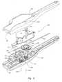
- One embodiment of the automatic driving mechanism 630is shown in detail in Fig. 6 .
- the automatic driving mechanism 630may comprise a gearbox assembly 629, and the gearbox assembly 629 may be selectably disengagable. According to the embodiment of Fig. 6 , once the automatic driving assembly 630 contacts the stop 261, further retraction of the closure device 200 automatically effects tamping of the sealing plug 210 ( Fig. 5F ).
- the suture 204is connected to and partially wound about a spool 632 of a first gear and spool assembly 631.
- the first gear and spool assembly 631includes both the spool 632 and a first gear 636 arranged on a first axis 635.
- the first gear 636is connected to the spool 632 and therefore they rotate together.
- Withdrawal of the closure device 200 ( Fig. 5F ) from the tissue puncture site 218if the anchor 208 ( Fig. 5F ) is deployed and the gearbox assembly 629 has contacted the stop 261) causes the suture 204 to unwind from the spool 632.
- the spool 632rotates as the suture 204 unwinds and provides a torsional motive force that is transduced to a linear tamping force.
- the torsional motive force provided by the spool 632is transduced into the linear tamping force by the gearbox assembly 629 according to the embodiment of Fig. 6 .
- the gearbox assembly 629includes the first gear 636 arranged coaxially with the spool 632. As shown in Fig. 6 , the first gear 636 may be arranged adjacent to a second gear 642. The second gear 642, when assembled, engages the first gear 636.
- the second gear 642is arranged on a second axis 640.
- the second gear 642may be a two-stage gear, with each stage engaging a different adjacent gear as shown.
- the first and second gears 636 and 642may engage one another with a frictional fit, or with meshed gear teeth as shown.
- the second gear 642is arranged adjacent to a third gear 643 on a third axis 645. When assembled, the second gear 642 engages and drives the third gear 643.
- the tamping tube 212is disposed between the third gear 643 and a guide 646.
- the tamping tube 212preferably includes the teeth shown, which mesh with teeth of the third gear 643.
- a concave holder 647may support the tamping tube 212.
- the spool 632rotates, it drives the tamping tube 212, which in turn tamps the sealing plug 210 ( Fig. 5F ).
- the tamping tube 212may not extend into the housing 252, and instead a separate rack may mesh with the third gear 643. The separate rack would, in turn, drive the tamping tube 212.
- the tamping tube 212is preferably semi-tubular and partially disposed about the suture 204 along its longitudinal axis.
- the semi-tubular shape of the tamping tube 212has a generally U-shaped cross section, and provides an open channel or trough 648 through which the suture 204 may enter and exit.
- the open channel 648permits the suture and the tamping tube 212 to merge as the spool 632 winds or unwinds.
- the suture 204 and the tamping tube 212are not fixedly connected to one another, allowing each to slide freely past the other. Accordingly, with the anchor 208 ( Fig. 5D ) deployed, as the closure device 200 ( Fig.
- the gearbox assembly 629may have an overall gear ratio greater than 1:1.
- the gear ratiomay range between approximately 1.5:1 and 3.0:1 for some embodiments, while the gear ratio is about 2.1:1 in other embodiments
- the linear velocity of the tamping tube 212should not be excessively greater than the linear velocity of withdrawal of the closure device, as excessive speed could potentially force the sealing plug 210 ( Fig. 5F ) through the tissue puncture 218 ( Fig. 5F ) and into the lumen 232 ( Fig. 5F ) of the artery 228 ( Fig. 5F ).
- an insufficient opposing force against the anchor 208 ( Fig. 5F )could potentially result in the anchor 208 ( Fig. 5F ) being pulled out of place from within the artery 228 ( Fig. 5F ). Therefore, according to some uses, the withdrawal force should not exceed approximately 2.5 pounds.
- gearbox assembly 629 configuration shown in Fig. 6is exemplary in nature, and not limiting. Any gear configuration (including a single gear) may be used to transmit a motive force generated by retraction of the suture 204 from the closure device 200 ( Fig. 5F ) to provide an automatic driving force to the sealing plug 210 ( Fig. 5F ) via the tamping tube 212.
- the gearbox assembly 629may be selectably disengagable. Therefore, one or more of the spool 632, first gear 636, second gear 642, and third gear 643 may be movable to disengage or manually disable adjacent gears. For example, one or more of the first gear 636, second gear 642, or third gear 643 may be movable along its respective axis to disengage from an adjacent gear. As shown in Fig. 6 , a biasing member such as a spring 649 is disposed at the second axis 640 biasing the second gear 642 into a meshed relationship with the first and third gears 636, 643.
- a biasing membersuch as a spring 649 is disposed at the second axis 640 biasing the second gear 642 into a meshed relationship with the first and third gears 636, 643.
- the second gear 642is movable along the second axis 640 by operation of an actuator 651 coupled to the second gear 642. Therefore, a force may be applied to the actuator 651 (following sliding movement of the gearbox assembly 629 to reach the stop 261, thereby aligning the actuator 651 with an access hole 253 in the handle 252) laterally with respect to the second gear 642, to overcome a biasing force provided by the spring 649 and move or displace the second gear 642 axially out of the meshed or contacting relationship with at least one of the first and third gears 636, 643. According to the embodiment of Fig. 6 , axial movement of the second gear 642 only disengages the second gear 642 from the first gear 636.
- Disengaging the gearbox assembly 629allows retraction of the closure device 200 ( Fig. 5F ) and unwinding of the suture 204 from the spool 632 without driving the tamping tube 212.
- the advantages of this disengagementare discussed below with reference to the operation of the closure device 200.
- the tamping tube 212may interlock with the second gear 642 in a first rack position shown, preventing premature activation of the actuator 651.
- the interlocking geometryis seen more clearly in Fig. 7 .
- the second gear 642may include a second gear hub 653 with an annular groove 655.
- the tamping tube 212is disposed in the annular groove 655 in the first rack position, which locks out the actuator 651.
- the tamping tuberests on the concave holder 647. Therefore, as long as the tamping tube 212 is disposed in the annular groove 655, the actuator 651 may not be depressed.
- the suture 204which is threaded through the anchor 208, unwinds from and causes rotation of the spool 632.
- the spool 632drives the first gear 636 as it rotates via the coaxial connection between the spool 632 and the first gear 636.
- the second gear 642drives the third gear 643, and the third gear 643 drives the tamping tube 212.
- the tamping tube 212tamps the sealing plug 210. Therefore, as the closing device 200 is retracted from the puncture tract 219, the procedure sheath 216 is retracted ( Figs.
- the sealing plug 210is more likely to create a sufficient arterial seal without a gap relative to the anchor 208, as may otherwise occur with a separate manual tamping procedure.
- the selectably disengagable gearbox assembly 629may be disengaged, enabling further retraction of the closure device 200 without additional tamping.
- the sealing plug 210fully tamped, there may be little or no portion of the suture 204 extending outside of the tissue layer 230 and exposed to an operator. Therefore, it may be difficult for an operator to separate the sealing plug 210 and anchor 208 from the remainder of the closure device 200.
- too much retraction with the selectably disengagable gearbox assembly 629 enabledcould potentially overtamp the sealing plug 210 into the artery 228.
- the selectably disengagable gearbox assembly 629may be advantageously disabled by activating the actuator 651 through the access hole 253. Activating the actuator 651 allows the suture 204 to fully unwind from the spool 632 without driving the tamping tube 212. Unwinding the spool 632 exposes a sufficient length of the suture 204 to allow an operator to easily cut it and separate the sealing plug 210 and anchor 208 from the remainder of the closure device 200.
- a selectably disengagable automatic driving mechanism 930may replace the selectably disengagable gearbox assembly 629 shown in Fig. 6 within the closure device 200 ( Fig. 5A ).
- the selectably disengagable automatic driving mechanism 930 of Fig. 9includes the suture 204 at least partially wound about a spool 932 of a first gear and spool assembly 931.
- the first gear and spool assembly 931includes both the spool 932 and a first gear 936 arranged on a first axis 935.
- the clutchmay be used to selectively connect and disconnect the first gear 936 from the spool 932.
- the clutchcomprises a plurality of release fingers 961 in Fig. 9 .
- the release fingers 961are arranged substantially in a circle.
- a first component 963 of the release fingers 961is cantilevered from the first gear 936 and extends normal to the first gear 936.
- a protrusion 965 of the first component 963extends radially outward and is received by a mating recess 967 of the spool 932.
- a second component 969 of the release fingers 961arcs substantially normal to the first component 963 and the first gear 936.
- the second component 969 of each of the release fingers 961extends through a central hole 971 of the spool 932.
- An actuator button 951fits over and contacts the second components 969 of each of the release fingers 961.
- the fit of the protrusions 965 of the first gear 936 with the mating recesses 967 of the spool 932causes the first gear 936 and spool 932 to rotate together at an identical angular velocity.
- the actuator button 951when the actuator button 951 is depressed, the actuator button slides along the arcs of the second component 969, forcing each of the release fingers 961 radially inward.
- the radial inward displacement of the release fingers 961at least partially removes the protrusions 965 from the mating recesses 967, allowing independent rotation of the spool 932 with respect to the first gear 936. Therefore, similar to the arrangement described above with reference to Figs.
- the selectably disengagable automatic driving mechanism 930is disengaged or disabled, allowing the suture 204 to safely unwind without further tamping. The suture 204 is then exposed to the operator for convenient cutting.
- the remaining components of the selectably disengagable automatic driving mechanism 930may be similar to the embodiment of Fig. 6 .
- Transducing the torsional motive force provided by the spool 932 to the linear tamping forceis achieved by a gear train 934.
- the gear train 934may include the first gear 936 and second and third gears 942, 943.
- the second gear 942engages and drives the third gear 943
- the third gear 943drives a tamping tube 212 or other sealing plug driving device.
- the second gear 942 of Fig. 9does not, however, include an annular groove interlocking with the tamping tube 212.
Landscapes
- Health & Medical Sciences (AREA)
- Surgery (AREA)
- Life Sciences & Earth Sciences (AREA)
- Biomedical Technology (AREA)
- Nuclear Medicine, Radiotherapy & Molecular Imaging (AREA)
- Engineering & Computer Science (AREA)
- Cardiology (AREA)
- Heart & Thoracic Surgery (AREA)
- Medical Informatics (AREA)
- Molecular Biology (AREA)
- Animal Behavior & Ethology (AREA)
- General Health & Medical Sciences (AREA)
- Public Health (AREA)
- Veterinary Medicine (AREA)
- Surgical Instruments (AREA)
Abstract
Description
- This invention relates generally to medical devices and more particularly to devices for sealing punctures or incisions in a tissue wall.
- Various surgical procedures are routinely carried out intravascularly or intraluminally. For example, in the treatment of vascular disease, such as arteriosclerosis, it is a common practice to invade the artery and insert an instrument (e.g., a balloon or other type of catheter) to carry out a procedure within the artery. Such procedures usually involve the percutaneous puncture of the artery so that an insertion sheath can be placed in the artery and thereafter instruments (e.g., catheter) can pass through the sheath and to an operative position within the artery. Intravascular and intraluminal procedures unavoidably present the problem of stopping the bleeding at the percutaneous puncture after the procedure has been completed and after the instruments (and any insertion sheaths used therewith) have been removed. Bleeding from puncture sites, particularly in the case of femoral arterial punctures, is typically stopped by utilizing vascular closure devices, such as those described in
U.S. Patent Nos. 6,179,963 ;6,090,130 ; and6,045,569 and related patents that are hereby incorporated by reference. - Typical closure devices such as the ones described in the above-mentioned patents place a sealing plug at the tissue puncture site. Successful deployment of the sealing plug, however, requires that it be manually ejected from within a carrier tube and tamped down to an outer surface of the tissue puncture using a tamping tube. However, it can be difficult to eject the sealing plug because the insertion sheath limits expansion of the carrier tube as the sealing plug is ejected. In addition, the tamping procedure cannot commence until the device sheath (within which the tamping tube is located) has been removed so as to expose the tamping tube for manual grasping. Under certain conditions, removal of the device prior to tamping the sealing plug could cause the sealing plug itself to be retracted from the tissue puncture, hindering subsequent placement of the sealing plug, and possibly resulting in only a partial seal and associated late bleeding from the tissue puncture. Accordingly, there is a need for improving the mechanism for deployment of the sealing plug at the site of a tissue puncture.
- The present invention meets the above-described needs and others. Specifically, the present invention provides medical devices, and methods and systems for closing internal tissue punctures. However, unlike prior systems, the present invention facilitates retraction of the procedure sheath and/or automatic tamping of a sealing plug. In addition, embodiments of the present invention allow the automatic tamping system to disengage, facilitating more complete retraction of the closure device and easy separation of the sealing plug from the remainder of the closure device.
- In one of many possible embodiments, the present invention provides a medical device. The medical device includes a handle, a filament extending from a first end at the handle to a second end, a sealing plug assembly attached to the filament at the second end, and an automatic tamping assembly slidingly mounted within the handle. The device may include a carrier tube extending from the handle and fixedly attached to the automatic tamping assembly, and a track disposed in the handle in which the automatic tamping assembly is slidingly mounted.
- According to some embodiments of the medical device, the automatic tamping assembly comprises a stowage detent. The stowage detent may be initially engaged with the handle, the stowage detent temporarily holding the automatic tamping assembly in a first position relative to the handle.
- According to some embodiments of the medical device, there is a first webbing track disposed in the handle. The first webbing track comprises a first width and a second width. The detent may be inserted into the first webbing track, where it traverses at least a portion of the first and second widths. The detent may include a finger biased to a third width greater than the first width. The finger may extend at least partially into the first webbing track at the second width in a first position to temporarily hold the automatic tamping assembly fast with respect to the handle.
- According to some embodiments of the medical device, the automatic tamping assembly may include a gearbox operatively connected to a tamping tube.
- According to some embodiments of the medical device, the sealing plug assembly comprises a sealing plug and an anchor, and the automatic tamping assembly comprises a tamping tube rack and a gearbox assembly. The gearbox assembly may include a first gear and spool assembly with a portion of the filament wound on the spool, such that the spool rotates and drives the first gear in a first direction, and the first gear drives the tamping tube rack, when the anchor is deployed through a tissue wall puncture and the medical device is retracted from the tissue wall puncture. The gearbox assembly may also include a second gear driven by the first gear, and a third gear driven by the second gear. The third gear may directly drive the tamping tube rack toward the anchor.
- According to some embodiments of the medical device, the automatic tamping assembly is free floating within the handle along a predetermined distance. In addition, a sheath may be attached to the handle in a fixed orientation. The handle and sheath may be retractable without changing the position of the carrier tube and automatic tamping assembly as the automatic tamping tube floats within the handle.
- Another embodiment of the invention provides a tissue wall puncture closure assembly. The tissue wall puncture closure assembly comprises a procedure sheath and a closure device inserted partially into the procedural sheath. The closure device comprises an anchor, a sealing plug, a handle, a filament extending between the anchor and the sealing plug and to the handle, a gearbox assembly disposed in the handle and connected to the filament, and a carrier tube fixed to the gearbox assembly and extending into the procedural sheath. The carrier tube houses the sealing plug, and the procedural sheath and the handle are retractable without moving the position of the carrier tube. The gearbox assembly is slidingly movable within the handle upon release of a gearbox detent.
- Another aspect of the invention provides a tissue puncture closure device for partial insertion into and sealing of an internal tissue wall puncture. The device comprises a filament extending from a first end of the closure device to a second end of the closure device, an anchor for insertion through the tissue wall puncture attached to the filament at the second end of the closure device, a sealing plug slidingly attached to the filament adjacent to the anchor, and a free-floating automatic driving mechanism for automatically tamping or cinching the sealing plug toward the second end upon withdrawal of the closure device from the internal tissue wall puncture. A tamping tube may be disposed adjacent to the sealing plug, and the tamping tube is driven by the free-floating automatic driving mechanism to tamp the sealing plug. The free-floating automatic driving mechanism may comprises a gearbox assembly for effecting a tamping force on the sealing plug upon withdrawal of the closure device from the tissue wall puncture. The free-floating automatic driving mechanism may also comprise a transducer for effecting a tamping force on the sealing plug upon withdrawal of the closure device from the tissue wall puncture. The transducer may comprise a first gear and spool assembly with a portion of the filament wound thereon, such that as the spool rotates, it drives the first gear in a first direction, and the first gear drives the tamping tube in a second direction.
- According to some embodiments of the device, the free-floating automatic driving mechanism is selectively disengagable and comprises a first gear and spool assembly on a first axis with a portion of the filament wound thereon, a second gear on a second axis adjacent to the first gear, a third gear on a third axis adjacent to the second gear. One of the first, second, or third gears is movable along its respective axis to operatively connect and disconnect the first, second, and third gears. For example, a biasing member on the second axis may bias the second gear into a meshed relationship with the first and third gears, and an actuator coupled to the second gear may be activated to selectively overcome the biasing member and move the second gear axially out of the meshed relationship with at least one of the first and third gears. Alternatively, there may be a manually operated clutch between the first gear and the spool assembly, the clutch operably connecting and disconnecting the spool to the first gear.
- Another embodiment of the invention provides a tissue puncture closure device for partial insertion into and sealing of a tissue puncture in an internal tissue wall accessible through a percutaneous incision. The device comprises a handle, an anchor for disposition on a distal side of the internal tissue wall, a sealing plug for disposition on a proximal side of the internal tissue wall, a filament connected to and anchored at a distal end to the anchor and sealing plug for slidably cinching the anchor and sealing plug together about the tissue puncture, such that the sealing plug is slidably disposed on the filament proximal to the anchor, a tamping device disposed on the filament for driving the sealing plug along the filament distally towards the anchor, and a gearbox assembly slidingly movable within the handle.
- Another aspect of the invention provides a method of sealing a tissue puncture in an internal tissue wall accessible through a percutaneous incision. The method comprises inserting a closure device into the tissue puncture through a procedure sheath, the closure device comprising a carrier tube, deploying an anchor inside the internal tissue wall, retracting the procedure sheath from tissue puncture without moving the carrier tube of the closure device, and setting a sealing plug at the tissue puncture. The method may also include attaching the closure device to the procedure sheath, retracting a handle of the closure device with the procedure sheath, and free floating the carrier tube within the closure device. Some aspects of the method may include automatically transducing a motive force generated by the retracting of the procedure sheath and closure device in a first direction to a tamping force in a second direction. The tamping force may be transferred to a rack that is slidingly disposed about a filament, the filament being connected to the sealing plug.
- According to some embodiments, the method includes attaching the closure device to the procedure sheath, retracting a handle of the closure device with the procedure sheath, free floating the carrier tube and a gearbox assembly within the closure device, automatically transducing a motive force generated by the retracting of the procedure sheath and closure device in a first direction to a tamping force in a second direction, and transferring the tamping force to a rack that is slidingly disposed about a filament, the filament being connected to the sealing plug. The transferring further comprises automatically unwinding the filament from a spool of the gearbox assembly by deploying an anchor attached to the filament inside the tissue puncture, and withdrawing the closure device from the tissue puncture. The transferring may further comprise driving a gears of the gearbox assembly, having one of the gears meshed with the rack, via the spool unwinding. The method may include manually disabling the tamping force by disengaging at least one gear of the gearbox assembly. The disengaging may comprises axially displacing at least one gear out of contact with an adjacent gear.
- According to some aspects of the method, the retracting the procedure sheath comprises exposing a distal portion of the carrier tube. The sealing plug may be more easily discharged from the carrier tube with the procedure sheath retracted.
- Another method of sealing a tissue puncture in an internal tissue wall accessible through a percutaneous incision is also provided. The method comprises providing a tissue puncture closure device comprising a handle, a filament anchored distally and connected to a sealing plug, the sealing plug for disposition at the tissue puncture, the tissue puncture closure device also comprising a free-floating automatic tamping device attached to a carrier tube. The method includes inserting the tissue puncture closure device through a procedure sheath and into the percutaneous incision, deploying the anchor into the tissue puncture, retracting the procedure sheath and the handle while maintaining a position of the anchor, the free-floating automatic tamping device, and the carrier tube; stopping the free-floating automatic tamping device and carrier tube against a stop, retracting the procedure sheath, the handle, the free-floating automatic tamping device, and the carrier tube together; and automatically tamping the sealing plug out of the carrier tube and toward the anchor in response to the retracting of the free-floating automatic tamping device. The method may also include disengaging the free-floating automatic tamping device, retracting the tissue puncture closure device further, exposing the filament, cutting the filament, and leaving the anchor and the sealing plug at the tissue puncture.
- Another aspect of the invention provides a medical device, comprising a handle, a carrier tube extending from the handle, a filament extending from the handle and through the carrier tube, a sealing plug slidingly attached to the filament, an anchor attached to the filament distal of the sealing plug, a displaceable gearbox assembly disposed within the handle, and a tamping tube rack at least partially disposed about the filament and extending from the gearbox assembly into the carrier tube. The gearbox assembly may comprise a detent holding the gearbox assembly in a first orientation with respect to the handle, where the detent is adapted to release upon application of a predetermined force between the gearbox and the handle.
- Additional advantages and novel features of the invention will be set forth in the description which follows or may be learned by those skilled in the art through reading these materials or practicing the invention. The advantages of the invention may be achieved through the means recited in the attached claims.
- The accompanying drawings illustrate various embodiments of the present invention and are a part of the specification. The illustrated embodiments are merely examples of the present invention and do not limit the scope of the invention.
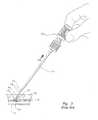
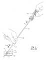
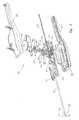
Fig. 1 is a partial cut-away view of a tissue closure device according to the prior art.Fig. 2 is a side view of the tissue closure device ofFig. 1 engaged with an artery according to the prior art.Fig. 3 is a side view of the tissue closure device ofFig. 1 being withdrawn from an artery according to the prior art to deploy a collagen sponge.Fig. 4 is a side view of the tissue closure device ofFig. 1 illustrating tamping of the collagen sponge according to the prior art.Fig. 5A is a perspective assembly view of a tissue puncture closure device with an automatic tamping or driving mechanism according to one embodiment of the present invention.Fig. 5B is a side view of the tissue closure device ofFig. 5A inserted into a procedure sheath and shown engaged with an artery in a first position according to one embodiment of the present invention.Fig. 5C is a detailed inset ofFig. 5B .Fig. 5D is a side view of the tissue closure device ofFig. 5A shown engaged with an artery in a second position retracting the procedure sheath according to one embodiment of the present invention.Fig. 5E is a detailed inset ofFig. 5D .Fig. 5F is a side view of the tissue closure device ofFig. 5A shown engaged with an artery in a third position tamping a sealing plug according to one embodiment of the present invention.Fig. 5G is a detailed inset ofFig. 5F .Fig. 6 illustrates the driving mechanism ofFig. 5A in a perspective assembly view with a carrier tube removed for clarity according to one embodiment of the present invention.Fig. 7 is a side cross sectional view of the driving mechanism ofFig. 6 according to one embodiment of the present invention.Fig. 8 is blown up perspective view of a portion of the driving mechanism and handle ofFig. 5A according to one embodiment of the present invention.Fig. 9 is a perspective assembly view of a tissue puncture closure device with an automatic tamping or driving mechanism according to another embodiment of the present invention.- Throughout the drawings, identical reference numbers designate similar, but not necessarily identical, elements.
- As mentioned above, vascular procedures are conducted throughout the world and require access to an artery through a puncture. Most often, the artery is a femoral artery. To close the puncture following completion of the procedure, many times a closure device is used to sandwich the puncture between an anchor and a sealing plug. However, sometimes the sealing plug is difficult to eject from the sealing device and may not properly seat against an exterior situs of the arteriotomy. If the plug does not seat properly against the arteriotomy, there is a potential for post-placement bleeding. The present invention describes methods and apparatus that facilitate sealing plug ejection and proper placement of the sealing plug. While the vascular instruments shown and described below include procedure sheaths and puncture sealing devices, the application of principles described herein are not limited to the specific devices shown. The principles described herein may be used with any medical device. Therefore, while the description below is directed primarily to arterial procedures and certain embodiments of a vascular closure device, the methods and apparatus are only limited by the appended claims.
- As used in this specification and the appended claims, the term "tamp" or "tamping" is used broadly to mean packing down by one or a succession of blows or taps or smooth, steady pressure, but not by excessive force. "Engage" and "engagable" are also used broadly to mean interlock, mesh, or contact between two devices. Likewise "disengage" or "disengagable" means to remove or capable of being removed from interlock, mesh, or contact. A "spool" is a cylinder or other device on which something else (e.g. a filament, suture, etc.) is at least partially wound. A "tube" is an elongated device with a passageway. The passageway may be enclosed or open (e.g. a trough). A "lumen" refers to any open space or cavity in a bodily organ, especially in a blood vessel. "Slidingly mounted" means movable relative to an appropriate support. A "detent" is a catch or lever that locks, at least temporarily, the movement of one part of a mechanism. "Free floating" means able to move freely according to at least one degree of freedom, at least after overcoming any initial holder. "Free floating" movement is not necessarily unlimited, and may include free movement only within a specified range. "Transduce" means to convert a force or other input energy in one form into output energy or forces of another form or direction. The term "effecting" means producing an outcome, achieving a result, or bringing about. The words "including" and "having," as used in the specification, including the claims, have the same meaning as the word "comprising."
- Referring now to the drawings, and in particular to
Figs. 1-4 , a vascularpuncture closure device 100 is shown according to the prior art. The vascularpuncture closure device 100 includes acarrier tube 102 with a filament orsuture 104 extending at least partially therethrough. Theclosure device 100 also includes a first orproximal end 106 and a second ordistal end 107. External to a second ordistal end 107 of thecarrier tube 102 is ananchor 108. The anchor is an elongated, stiff, low profile member including aneye 109 formed at the middle. Theanchor 108 is typically made of a biologically resorbable polymer. - The
suture 104 is threaded through theanchor 108 and back to acollagen pad 110. Thecollagen pad 110 may be comprised of randomly oriented fibrous material bound together by chemical means. Thecollagen pad 110 is slidingly attached to thesuture 104 as the suture passes distally through thecarrier tube 102, but as the suture traverses theanchor 108 and reenters thecarrier tube 102, it is securely slip knotted proximal to thecollagen pad 110 to facilitate cinching of thecollagen pad 110 when theclosure device 100 is properly placed and theanchor 108 deployed (seeFig. 4 ). Thecarrier tube 102 typically includes a tampingtube 112 disposed therein. The tampingtube 112 is slidingly mounted on thesuture 104 and may be used by an operator to tamp thecollagen pad 110 toward theanchor 108 at an appropriate time to seal a percutaneous tissue puncture. - Prior to deployment of the
anchor 108 within an artery, theeye 109 of theanchor 108 rests outside thedistal end 107 of thecarrier tube 102. Theanchor 108 may be temporarily held in place flush with thecarrier tube 102 by abypass tube 114 disposed over thedistal end 107 of thecarrier tube 102. - The flush arrangement of the
anchor 108 andcarrier tube 102 allows theanchor 108 to be inserted into a procedure sheath such asinsertion sheath 116 as shown inFigs. 2-4 , and eventually through anarterial puncture 118. Theinsertion sheath 116 is shown inFigs. 2-4 inserted through apercutaneous incision 119 and into anartery 128. However, the bypass tube 114 (Fig. 1 ) includes anoversized head 120 that prevents thebypass tube 114 from passing through an internal passage of theinsertion sheath 116. Therefore, as thepuncture closure device 100 is inserted into theinsertion sheath 116, theoversized head 120 bears against asurface 122 ofinsertion sheath 116. Further insertion of thepuncture closure device 100 results in sliding movement between the carrier tube 102 (Fig. 1 ) and thebypass tube 114, releasing theanchor 108 from the bypass tube 114 (Fig. 1 ). However, theanchor 108 remains in the flush arrangement shown inFig. 1 following release from thebypass tube 114, limited in movement by theinsertion sheath 116. - The
insertion sheath 116 includes amonofold 124 at a second ordistal end 126 thereof. Themonofold 124 acts as a one-way valve to theanchor 108. Themonofold 124 is a plastic deformation in a portion of theinsertion sheath 116 that elastically flexes as theanchor 108 is pushed out through thedistal end 126 of theinsertion sheath 116. Typically, after theanchor 108 passes through thedistal end 126 of theinsertion sheath 116 and enters theartery 128, theanchor 108 is no longer constrained to the flush arrangement with respect to thecarrier tube 102 and it deploys and rotates to the position shown inFig. 2 . - Referring next to
Figs. 3-4 , with theanchor 108 deployed, thepuncture closure device 100 and theinsertion sheath 116 are withdrawn together, ejecting thecollagen pad 110 from thecarrier tube 102 into theincision tract 119 and exposing the tampingtube 112. With the tampingtube 112 fully exposed as shown inFig. 4 , thecollagen pad 110 is manually tamped, and theanchor 108 andcollagen pad 110 are cinched together and held in place with the self-tightening slip-knot on thesuture 102. Thus, the tissue puncture is sandwiched between theanchor 108 and thecollagen pad 110, thereby sealing thetissue puncture 118. Thesuture 104 is then cut and theincision tract 119 may be closed. Thesuture 104,anchor 108, andcollagen pad 110 are generally made of resorbable materials and therefore remain in place while thepuncture 118 heals. - Using the typical tissue
puncture closure device 100 described above, however, it may be difficult to eject and tamp of thecollagen pad 110. Theinsertion sheath 116 resists deformation as thecollagen pad 110 is ejected from the carrier tube. Also, tamping cannot commence until thesheath 116 has been removed to a position above the patient skin surface so as to expose the tampingtube 112 for manual grasping. Under certain conditions, removal of thesheath 116 prior to tamping thecollagen pad 110 causes thecollagen pad 110 to retract from thetissue puncture 118, creating anundesirable gap 120 between thecollagen pad 110 and thepuncture 118. Thegap 120 may remain even after tamping as shown inFig. 4 , and sometimes results in only a partial seal and associated bleeding from thetissue puncture 118. - Therefore, the present specification describes a medical device such as a tissue puncture closure device that is capable of retracting a procedural sheath relative to a closure device, exposing a distal end of the closure device prior to ejecting a sealing plug. The closure device also automatically drives the sealing plug toward a tissue puncture upon withdrawal of the tissue puncture closure device from the tissue puncture site. The mechanism for automatically driving the sealing plug may be selectably disengagable.
- As described above, the general structure and function of tissue closure devices used for sealing a tissue puncture in an internal tissue wall accessible through an incision in the skin are well known in the art. Applications of closure devices including those implementing principles described herein include closure of a percutaneous puncture or incision in tissue separating two internal portions of a living body, such as punctures or incisions in blood vessels, ducts or lumens, gall bladders, livers, hearts, etc.
- Referring now to
Figs. 5A-5G , a medical device, for example a tissue wallpuncture closure device 200, is shown according to one embodiment of the present invention. Theclosure device 200 is shown in an assembly view inFig. 5A .Figs. 5B-5G illustrate theclosure device 200 assembled and inserted through aprocedure sheath 216 and into alumen 232. Theclosure device 200 has particular utility when used in connection with intravascular procedures, such as angiographic dye injection, cardiac catheterization, balloon angioplasty and other types of recanalizing of atherosclerotic arteries, etc. as theclosure device 200 is designed to cause immediate hemostasis of the blood vessel (e.g., arterial) puncture. However, it will be understood that while the description of the preferred embodiments below are directed to the sealing off of percutaneous punctures in arteries, such devices have much more wide-spread applications and can be used for sealing punctures or incisions in other types of tissue walls as well. Thus, the sealing of a percutaneous puncture in an artery, shown herein, is merely illustrative of one particular use of theclosure device 200 of the present invention. - The
closure device 200 includes a first orproximal end portion 206 and a second ordistal end portion 207. Acarrier tube 202 extends from theproximal end portion 206 to thedistal end portion 207 and includes anoutlet 213 at thedistal end portion 207. Thedistal end portion 207 may include aslit 209. - The
carrier tube 202 may be made of plastic or other material and is designed for insertion through the procedure sheath 216 (Fig. 5B ). The procedure sheath 216 (Fig. 5B ) is designed for insertion through a percutaneous incision 219 (Fig. 5B ) in atissue layer 230 and into thelumen 232. According toFigs. 5B-5G , thelumen 232 comprises an interior portion of afemoral artery 228. - At the
distal end portion 207 of thecarrier tube 202 there is ananchor 208 and a sealing plug 210 (Fig. 5B ). Theanchor 208 of the present embodiment is an elongated, stiff, low-profile member arranged to be seated inside the artery 228 (Fig. 5B ) against an artery wall 234 (Fig. 5B ) contiguous with a puncture 218 (Fig. 5B ). Theanchor 208 is preferably made of a biologically resorbable polymer. The sealing plug 210 (Fig. 5B ) is formed of a compressible sponge, foam, or fibrous mat made of a hemostatic biologically resorbable material such as collagen, and may be configured in any shape so as to facilitate sealing thetissue puncture 218. - The sealing
plug 210 andanchor 208 are connected to one another by a filament orsuture 204 that is also biologically resorbable. Theanchor 208, the sealingplug 210, and thesuture 204 are collectively referred to as the "closure elements" below. As shown inFig. 5A , theanchor 208 is initially arranged adjacent to and exterior of thedistal end portion 207 of thecarrier tube 202, while the sealing plug 210 (Fig. 5B ) is initially disposed within thecarrier tube 202. Theanchor 208 is shown nested in its low profile configuration along thecarrier tube 202 to facilitate insertion into thelumen 232 inFig. 5A , and deployed with a first surface 236 abutting theartery wall 234 inFigs. 5B-5G . Thesuture 204 extends distally from thefirst end portion 206 of theclosure device 200 through thecarrier tube 202. Thesuture 204 may be threaded through one or more perforations in the sealingplug 210, through a hole in theanchor 208, and proximally back toward thecarrier tube 202 to the sealingplug 210. Thesuture 204 is preferably threaded again through a perforation or series of perforations in the sealingplug 210. Thesuture 204 may also be threaded around itself to form a self-tightening slip-knot. Thesuture 204 may thus connect theanchor 208 and the sealingplug 210 in a pulley-like arrangement to cinch theanchor 208 and the sealingplug 210 together when thecarrier tube 202 is pulled away from theanchor 208 and the sealingplug 210. Theanchor 208 and the sealingplug 210 sandwich and lock the anchor and plug together, sealing thetissue puncture 218. - The
carrier tube 202 houses a tamping device, such as a tamping tube 212 (Fig. 5C ), for advancing the sealingplug 210 along thesuture 204 and toward theanchor 208. The tampingtube 212 is shown located partially within thecarrier tube 202 and proximal of the sealingplug 208. The tampingtube 212, however, also extends through a handle 252 (Fig. 5A ) of theclosure device 200. The tampingtube 212 is preferably an elongated tubular or semi-tubular rack that may be rigid or flexible and formed of any suitable material. For example, according to one embodiment, the tampingtube 212 is made of polyurethane. Thesuture 204 extends through at least a portion of the tampingtube 212. For example, as shown inFigs. 5A-5G , thesuture 204 extends along the tampingtube 212 between the first andsecond end portions suture 204 is not directly connected to the tampingtube 212. Accordingly, thesuture 204 and the tampingtube 212 may slide past one another. - According to the embodiment of
Figs. 5A-5G , thesuture 204 attaches to an automatic tamping assembly. The automatic tamping assembly may include anautomatic driving mechanism 630 or other transducer, and the tampingtube 212. Theautomatic driving mechanism 630 is located within the housing or handle 252 at thefirst end portion 206 of theclosure device 200. Embodiments of theautomatic driving mechanism 630 are described in detail below with reference toFigs. 6 - 9 . The tampingtube 212 may comprise a rack receptive of gear teeth (discussed in more detail below). - In practice, the
carrier tube 202 of the closure device 200 (containing the closure elements described above) is inserted into theinsertion sheath 216, which is already inserted within the artery 228 (Figs. 5B-5C ). As theclosure device 200 and the associated closure elements are inserted into theprocedure sheath 216, theanchor 208 passes through and out of the distal end of theprocedure sheath 216 and is inserted into theartery lumen 232. As mentioned above and shown inFig. 5A , theanchor 208 is initially arranged substantially flush with thecarrier tube 202 to facilitate insertion of theanchor 208 through the percutaneous incision 219 (Fig. 5B ) and into thelumen 232. - After the
anchor 208 passes out of the distal end of theprocedure sheath 216, however, it tends to deploy or rotate to the position shown inFigs. 5B-5C . Theclosure device 200 may also be partially withdrawn from theinsertion sheath 216, catching theanchor 208 on the distal end of theinsertion sheath 216 and rotating it to the position shown inFigs. 5B-5C . However, theclosure device 200 preferably includes a pair of biasedfingers 215 that are lockingly received by a matching pair ofrecesses 217 in theprocedure sheath 216. The locking arrangement between thebiased fingers 215 and matchingrecesses 217 preferably fixes the position of thehandle 252 relative to theprocedure sheath 216. - Following deployment of the
anchor 208, thehandle 252 and theinsertion sheath 216 are locked together and will be withdrawn as a single unit. Withdrawing thehandle 252 causes theanchor 208 to anchor itself within theartery 228 against theartery wall 234. With theanchor 208 anchored within theartery 228 at thepuncture site 218, further retraction of thehandle 252 andinsertion sheath 216 tends to eject the sealingplug 210 from thedistal end portion 207 of thecarrier tube 202, thereby depositing theplug 210 within the incision orpuncture tract 219. The slit 209 (Fig. 5A ) in thecarrier tube 202 allows thedistal end portion 207 of the carrier tube to flex or open, facilitating ejection of the sealingplug 210. However, the slit 209 (Fig. 5A ) at thedistal end portion 207 of thecarrier tube 202 may be prevented from opening or flexing by the presence of theprocedure sheath 216, which is concentric with thecarrier tube 202. Therefore, according to principles of the present invention, retraction of thehandle 252 andinsertion sheath 216 causes theinsertion sheath 216 to retract with respect to thecarrier tube 202 to a second position shown inFigs. 5D-5E . - Referring to
Figs. 5D-5E , thedistal end portion 207 of thecarrier tube 202 is exposed (within the incision tract 219) as thehandle 252 and theprocedure sheath 216 are retracted. Thecarrier tube 202 retains its position relative to thepuncture 218 until thehandle 252 and theprocedure sheath 216 have been retracted a predetermined distance. Relative movement between thehandle 252/procedure sheath 216 and thecarrier tube 202 is facilitated by a sliding mount arrangement between theautomatic driving mechanism 630 and thehandle 252. - As shown by the combination of
Figs. 5B-5G , the automatic driving mechanism 630 (which is attached to the carrier tube 202) is free floating or displaceable and slides relative to thehandle 252 as thehandle 252 and theprocedure sheath 216 are retracted. However, theautomatic driving mechanism 630 may be initially held in a first position relative to thehandle 252 as shown inFigs. 5B and8 . For example, as shown inFig. 8 , theautomatic driving mechanism 630 may comprise a temporary holder such as astowage detent 255 slidingly mounted in a track. The track is shown inFig. 8 as awebbing track 253. Thewebbing track 253 is disposed in thehandle 252. Thewebbing track 253 may have a first width W1 and a second width W2. Thestowage detent 255 may include afinger 257 with aprotrusion 259 biased to a third width W3 greater than the first width W1, but less than the second width W2. Thefinger 257 extends at least partially into thewebbing track 253 at the second width W2 to at least temporarily hold theautomatic driving mechanism 630 in the first position shown inFigs. 5B and8 , and prevent premature sliding within thehandle 252. - Although the
finger 257 tends to hold or temporarily lock theautomatic driving mechanism 630 in the first position shown inFigs. 5B and8 , thefinger 257 releases when a sufficient predetermined force is applied between thehandle 252 and theautomatic driving mechanism 630. For example, with theanchor 208 deployed, a retraction force provided by a user to thehandle 252 causes thefinger 257 to deflect inward and slide distally toward the first width W1 portion of thewebbing track 253. When theprotrusion 259 of the finger enters the first width W1, thestowage detent 255 is "released" and provides very little resistance to sliding movement between theautomatic driving mechanism 630 and thehandle 252. Accordingly, retraction of thehandle 252 retracts the procedure sheath 216 (which is fixedly connected to the handle 252), but theautomatic driving mechanism 630 and thecarrier tube 202 slide relative to thehandle 252 and therefore remain in position with respect to thepuncture 218. Theautomatic driving mechanism 630 may slide a predetermined distance with respect to thehandle 252 until theautomatic driving mechanism 630 reaches a stop 261 (Fig. 5d ). The predetermined distance is preferably at least long enough to fully expose the slit 209 (Fig. 5A ) in thecarrier tube 202. - When the
automatic driving mechanism 630 reaches the stop 261 (Fig. 5D ), further retraction of thehandle 252 withdraws thecarrier tube 202 as well, ejecting and tamping the sealingplug 210 automatically as shown inFigs. 5F-5G . Unlike previous closure devices that require a separate, manual tamping procedure following the deposition of the sealingplug 210, theclosure device 200 of the present invention automatically tamps the sealingplug 210. The sealingplug 210 is tamped while thecarrier tube 202 is being withdrawn, reducing or eliminating any gaps that may otherwise occur between the sealingplug 210 and thepuncture 218 in thefemoral artery 228. - In addition, by placing tension on or pulling the
suture 204 away from thepuncture tract 219, thesuture 204 may cinch and lock (with a slip knot or the like) together theanchor 208 and the sealingplug 210, sandwiching theartery wall 234 between theanchor 208 and sealingplug 210. The force exerted by the tampingtube 212 and the cinching together of theanchor 208 and sealingplug 210 by thefilament 204 also causes the sealingplug 210 to deform radially outward within thepuncture tract 219 and function as an anchor on the proximal side of thetissue puncture site 218 as shown inFigs. 5F-5G . - The tamping
tube 212 is automatically driven toward the sealingplug 210 by theautomatic driving mechanism 630. One embodiment of theautomatic driving mechanism 630 is shown in detail inFig. 6 . Theautomatic driving mechanism 630 may comprise agearbox assembly 629, and thegearbox assembly 629 may be selectably disengagable. According to the embodiment ofFig. 6 , once theautomatic driving assembly 630 contacts thestop 261, further retraction of theclosure device 200 automatically effects tamping of the sealing plug 210 (Fig. 5F ). - According to the
gearbox assembly 629 ofFig. 6 , thesuture 204 is connected to and partially wound about aspool 632 of a first gear andspool assembly 631. The first gear andspool assembly 631 includes both thespool 632 and afirst gear 636 arranged on afirst axis 635. According to the embodiment ofFig. 6 , thefirst gear 636 is connected to thespool 632 and therefore they rotate together. Withdrawal of the closure device 200 (Fig. 5F ) from the tissue puncture site 218 (if the anchor 208 (Fig. 5F ) is deployed and thegearbox assembly 629 has contacted the stop 261) causes thesuture 204 to unwind from thespool 632. Thespool 632 rotates as thesuture 204 unwinds and provides a torsional motive force that is transduced to a linear tamping force. - The torsional motive force provided by the
spool 632 is transduced into the linear tamping force by thegearbox assembly 629 according to the embodiment ofFig. 6 . Thegearbox assembly 629 includes thefirst gear 636 arranged coaxially with thespool 632. As shown inFig. 6 , thefirst gear 636 may be arranged adjacent to asecond gear 642. Thesecond gear 642, when assembled, engages thefirst gear 636. Thesecond gear 642 is arranged on asecond axis 640. Thesecond gear 642 may be a two-stage gear, with each stage engaging a different adjacent gear as shown. The first andsecond gears second gear 642 is arranged adjacent to athird gear 643 on athird axis 645. When assembled, thesecond gear 642 engages and drives thethird gear 643. - The tamping
tube 212 is disposed between thethird gear 643 and aguide 646. The tampingtube 212 preferably includes the teeth shown, which mesh with teeth of thethird gear 643. Aconcave holder 647 may support the tampingtube 212. When thespool 632 rotates, it drives the tampingtube 212, which in turn tamps the sealing plug 210 (Fig. 5F ). Alternatively, the tampingtube 212 may not extend into thehousing 252, and instead a separate rack may mesh with thethird gear 643. The separate rack would, in turn, drive the tampingtube 212. - The tamping
tube 212 is preferably semi-tubular and partially disposed about thesuture 204 along its longitudinal axis. The semi-tubular shape of the tampingtube 212 has a generally U-shaped cross section, and provides an open channel ortrough 648 through which thesuture 204 may enter and exit. Theopen channel 648 permits the suture and the tampingtube 212 to merge as thespool 632 winds or unwinds. Thesuture 204 and the tampingtube 212 are not fixedly connected to one another, allowing each to slide freely past the other. Accordingly, with the anchor 208 (Fig. 5D ) deployed, as the closure device 200 (Fig. 5F ) is retracted in a first direction with thegearbox assembly 629 bearing against the stop 261 (Fig. 5F ), thesuture 204 unwinds from thespool 632, which drives thegearbox assembly 629. Thegearbox assembly 629 drives the tampingtube 212 in a second, opposite direction, and the tamping tube tamps the sealing plug 210 (Fig. 5F ). - It may be desirable in some cases to increase the linear velocity of the tamping
tube 212 relative to the linear velocity at which the closure device 200 (Fig. 5F ) is withdrawn. Increasing the linear velocity for the tampingtube 212 may better assure that the sealing plug 210 (Fig. 5F ) is forced toward the anchor 208 (Fig. 5F ) when the closure device 200 (Fig. 5F ) is withdrawn in an opposite direction. Therefore, according to some embodiments, thegearbox assembly 629 may have an overall gear ratio greater than 1:1. For example, the gear ratio may range between approximately 1.5:1 and 3.0:1 for some embodiments, while the gear ratio is about 2.1:1 in other embodiments - However, it should be noted that the linear velocity of the tamping
tube 212 should not be excessively greater than the linear velocity of withdrawal of the closure device, as excessive speed could potentially force the sealing plug 210 (Fig. 5F ) through the tissue puncture 218 (Fig. 5F ) and into the lumen 232 (Fig. 5F ) of the artery 228 (Fig. 5F ). Likewise, an insufficient opposing force against the anchor 208 (Fig. 5F ) could potentially result in the anchor 208 (Fig. 5F ) being pulled out of place from within the artery 228 (Fig. 5F ). Therefore, according to some uses, the withdrawal force should not exceed approximately 2.5 pounds. - It will be understood by those of skill in the art having the benefit of this disclosure that the
gearbox assembly 629 configuration shown inFig. 6 is exemplary in nature, and not limiting. Any gear configuration (including a single gear) may be used to transmit a motive force generated by retraction of thesuture 204 from the closure device 200 (Fig. 5F ) to provide an automatic driving force to the sealing plug 210 (Fig. 5F ) via the tampingtube 212. - As mentioned above, the
gearbox assembly 629 may be selectably disengagable. Therefore, one or more of thespool 632,first gear 636,second gear 642, andthird gear 643 may be movable to disengage or manually disable adjacent gears. For example, one or more of thefirst gear 636,second gear 642, orthird gear 643 may be movable along its respective axis to disengage from an adjacent gear. As shown inFig. 6 , a biasing member such as aspring 649 is disposed at thesecond axis 640 biasing thesecond gear 642 into a meshed relationship with the first andthird gears second gear 642 is movable along thesecond axis 640 by operation of anactuator 651 coupled to thesecond gear 642. Therefore, a force may be applied to the actuator 651 (following sliding movement of thegearbox assembly 629 to reach thestop 261, thereby aligning theactuator 651 with anaccess hole 253 in the handle 252) laterally with respect to thesecond gear 642, to overcome a biasing force provided by thespring 649 and move or displace thesecond gear 642 axially out of the meshed or contacting relationship with at least one of the first andthird gears Fig. 6 , axial movement of thesecond gear 642 only disengages thesecond gear 642 from thefirst gear 636. Disengaging thegearbox assembly 629 allows retraction of the closure device 200 (Fig. 5F ) and unwinding of thesuture 204 from thespool 632 without driving the tampingtube 212. The advantages of this disengagement are discussed below with reference to the operation of theclosure device 200. - However, as shown in
Figs. 6-7 , the tampingtube 212 may interlock with thesecond gear 642 in a first rack position shown, preventing premature activation of theactuator 651. The interlocking geometry is seen more clearly inFig. 7 . Thesecond gear 642 may include asecond gear hub 653 with anannular groove 655. The tampingtube 212 is disposed in theannular groove 655 in the first rack position, which locks out theactuator 651. The tamping tube rests on theconcave holder 647. Therefore, as long as the tampingtube 212 is disposed in theannular groove 655, theactuator 651 may not be depressed. With the tampingtube 212 disposed in theannular groove 655, forces applied to theactuator 651 are transmitted to thesecond gear 642, but the second gear is prevented from moving axially by the rack disposed in theannular groove 655 and supported by theconcave holder 647. Nevertheless, retracting the closure device 200 (Fig. 5F ) results in rotation of the gears of thegearbox assembly 629, and linear movement of the tampingtube 212. When the tampingtube 212 has moved a predetermined distance to a second tamping tube position sufficient to cause effective tamping of the sealing plug 210 (Fig. 5F ), the tampingtube 212 also moves out of the annular groove 655 (SeeFig. 5F ). Therefore, theactuator 651 is no longer locked out, and thesecond gear 642 may be disengaged once the tampingtube 212 has moved linearly the predetermined distance. - Operation of the embodiment of
Figs. 5A-8 is as follows. As thehandle 252 of theclosing device 200 is retracted from thepuncture tract 219 as shown inFig. 5B , thedetent 255 releases. Theautomatic tamping mechanism 630 andcarrier tube 202 remain stationary and therefore float relative to thehandle 252. Theprocedure sheath 216 is retracted as thehandle 252 is withdrawn, exposing thedistal end 207 of thecarrier tube 202. Theautomatic tamping mechanism 630 eventually contacts astop 261, and further retraction causes theautomatic tamping mechanism 630 andcarrier tube 202 to retract as well. As theautomatic tamping mechanism 630 retracts, thesuture 204, which is threaded through theanchor 208, unwinds from and causes rotation of thespool 632. Thespool 632 drives thefirst gear 636 as it rotates via the coaxial connection between thespool 632 and thefirst gear 636. As thefirst gear 636 rotates, it drives thesecond gear 642. Thesecond gear 642 drives thethird gear 643, and thethird gear 643 drives the tampingtube 212. The tampingtube 212 tamps the sealingplug 210. Therefore, as theclosing device 200 is retracted from thepuncture tract 219, theprocedure sheath 216 is retracted (Figs. 5D-5E ), and the sealingplug 210 is automatically tamped (Figs. 5F-5G) . The sealingplug 210 is more likely to create a sufficient arterial seal without a gap relative to theanchor 208, as may otherwise occur with a separate manual tamping procedure. - Moreover, when the sealing
plug 210 has been sufficiently tamped, the selectably disengagablegearbox assembly 629 may be disengaged, enabling further retraction of theclosure device 200 without additional tamping. With the sealingplug 210 fully tamped, there may be little or no portion of thesuture 204 extending outside of thetissue layer 230 and exposed to an operator. Therefore, it may be difficult for an operator to separate the sealingplug 210 andanchor 208 from the remainder of theclosure device 200. In addition, too much retraction with the selectably disengagablegearbox assembly 629 enabled could potentially overtamp the sealingplug 210 into theartery 228. Accordingly, the selectably disengagablegearbox assembly 629 may be advantageously disabled by activating theactuator 651 through theaccess hole 253. Activating theactuator 651 allows thesuture 204 to fully unwind from thespool 632 without driving the tampingtube 212. Unwinding thespool 632 exposes a sufficient length of thesuture 204 to allow an operator to easily cut it and separate the sealingplug 210 andanchor 208 from the remainder of theclosure device 200. - Referring next to
Fig. 9 , another embodiment of a selectably disengagableautomatic driving mechanism 930 is shown. The selectably disengagableautomatic driving mechanism 930 ofFig. 9 may replace the selectably disengagablegearbox assembly 629 shown inFig. 6 within the closure device 200 (Fig. 5A ). Similar to the embodiment ofFig. 6 , the selectably disengagableautomatic driving mechanism 930 ofFig. 9 includes thesuture 204 at least partially wound about aspool 932 of a first gear andspool assembly 931. The first gear andspool assembly 931 includes both thespool 932 and afirst gear 936 arranged on afirst axis 935. However, according to the embodiment ofFig. 9 , thefirst gear 936 and thespool 932 form a manually operated clutch therebetween. The clutch may be used to selectively connect and disconnect thefirst gear 936 from thespool 932. The clutch comprises a plurality ofrelease fingers 961 inFig. 9 . Therelease fingers 961 are arranged substantially in a circle. Afirst component 963 of therelease fingers 961 is cantilevered from thefirst gear 936 and extends normal to thefirst gear 936. Aprotrusion 965 of thefirst component 963 extends radially outward and is received by amating recess 967 of thespool 932. Asecond component 969 of therelease fingers 961 arcs substantially normal to thefirst component 963 and thefirst gear 936. Thesecond component 969 of each of therelease fingers 961 extends through a central hole 971 of thespool 932. Anactuator button 951 fits over and contacts thesecond components 969 of each of therelease fingers 961. - The fit of the
protrusions 965 of thefirst gear 936 with the mating recesses 967 of thespool 932 causes thefirst gear 936 andspool 932 to rotate together at an identical angular velocity. However, when theactuator button 951 is depressed, the actuator button slides along the arcs of thesecond component 969, forcing each of therelease fingers 961 radially inward. The radial inward displacement of therelease fingers 961 at least partially removes theprotrusions 965 from the mating recesses 967, allowing independent rotation of thespool 932 with respect to thefirst gear 936. Therefore, similar to the arrangement described above with reference toFigs. 5A-8 , after the sealingplug 210 is driven toward theanchor 208, the selectably disengagableautomatic driving mechanism 930 is disengaged or disabled, allowing thesuture 204 to safely unwind without further tamping. Thesuture 204 is then exposed to the operator for convenient cutting. - The remaining components of the selectably disengagable
automatic driving mechanism 930 may be similar to the embodiment ofFig. 6 . Transducing the torsional motive force provided by thespool 932 to the linear tamping force is achieved by agear train 934. Thegear train 934 may include thefirst gear 936 and second andthird gears second gear 942 engages and drives thethird gear 943, and thethird gear 943 drives a tampingtube 212 or other sealing plug driving device. Thesecond gear 942 ofFig. 9 does not, however, include an annular groove interlocking with the tampingtube 212. - The preceding description has been presented only to illustrate and describe exemplary embodiments of invention. It is not intended to be exhaustive or to limit the invention to any precise form disclosed. Many modifications and variations are possible in light of the above teaching. It is intended that the scope of the invention be defined by the following claims.
Claims (15)
- A medical device, comprising:a handle;a filament extending from a first end at the handle to a second end;a sealing plug assembly attached to the filament at the second end;an automatic tamping assembly slidingly mounted within the handle.
- A medical device according to claim 1, further comprising a carrier tube extending from the handle and fixedly attached to the automatic tamping assembly.
- A medical device according to claim 1, further comprising a track disposed in the handle in which the automatic tamping assembly is slidingly mounted.
- A medical device according to claim 1, wherein the automatic tamping assembly comprises a stowage detent.
- A medical device according to claim 1, wherein the automatic tamping assembly comprises a stowage detent engaged with the handle, the stowage detent temporarily holding the gearbox assembly in a first position relative to the handle.
- A medical device according to claim 1, further comprising:a webbing track disposed in the handle, the webbing track comprising a first width and a second width;wherein the automatic tamping assembly comprises a detent inserted into the webbing track and traversing at least a portion of the first and second widths.
- A medical device according to claim 1, further comprising:a webbing track disposed in the handle, the webbing track comprising a first width and a second width;wherein the automatic tamping assembly comprises a finger biased to a third width greater than the first width;
wherein the finger extends at least partially into the webbing track at the second width in a first position to temporarily hold the automatic tamping assembly fast with respect to the handle. - A medical device according to claim 1 wherein the automatic tamping assembly comprises a gearbox operatively connected to a tamping tube.
- A medical device according to claim 1:
wherein the sealing plug assembly comprises a sealing plug and an anchor;
wherein the automatic tamping assembly comprises a tamping tube rack and a gearbox assembly, the gearbox assembly comprising:a first gear and spool assembly with a portion of the filament wound on the spool;wherein the spool rotates and drives the first gear in a first direction, and the first gear drives the tamping tube rack when the anchor is deployed through a tissue wall puncture and the medical device is retracted from the tissue wall puncture. - A medical device according to claim 1:
wherein the sealing plug assembly comprises a sealing plug and an anchor;
wherein the automatic tamping assembly comprises:a tamping tube rack;
a first gear and spool assembly with a portion of the filament wound on the spool;a second gear driven by the first gear;a third gear driven by the second gear;wherein the third gear drives the tamping tube rack toward the anchor when the anchor is deployed in a blood vessel and the medical device is retracted from the blood vessel. - A medical device according to claim 1 wherein the automatic tamping assembly is free floating within the handle a predetermined distance.
- A medical device according to claim 1, further comprising a sheath attached to the handle in a fixed orientation.
- A medical device according to claim 1, further comprising:a carrier tube extending from the handle and fixedly attached to the automatic tamping assembly;a sheath attached to the handle in a fixed orientation;wherein the handle and sheath are retractable without changing the position of the carrier tube and automatic tamping assembly.
- A medical device, comprising:a handle;a carrier tube extending from the handle;a filament extending from the handle and through the carrier tube;a sealing plug slidingly attached to the filament;an anchor attached to the filament distal of the sealing plug;a displaceable gearbox assembly disposed within the handle;a tamping tube rack at least partially disposed about the filament and extending from the gearbox assembly into the carrier tube.
- A medical device according to claim 14, wherein the gearbox assembly comprises a detent holding the gearbox assembly in a first orientation with respect to the handle, wherein the detent is adapted to release upon application of a predetermined force between the gearbox and the handle.
Applications Claiming Priority (2)
| Application Number | Priority Date | Filing Date | Title |
|---|---|---|---|
| US11/130,895US7837705B2 (en) | 2005-05-17 | 2005-05-17 | Tissue puncture closure system with retractable sheath |
| EP06758734AEP1893099B1 (en) | 2005-05-17 | 2006-04-28 | Tissue puncture closure system with retractable sheath |
Related Parent Applications (1)
| Application Number | Title | Priority Date | Filing Date |
|---|---|---|---|
| EP06758734.5Division | 2006-04-28 |
Publications (2)
| Publication Number | Publication Date |
|---|---|
| EP2213247A1true EP2213247A1 (en) | 2010-08-04 |
| EP2213247B1 EP2213247B1 (en) | 2013-06-12 |
Family
ID=37431759
Family Applications (2)
| Application Number | Title | Priority Date | Filing Date |
|---|---|---|---|
| EP10157302.0AActiveEP2213247B1 (en) | 2005-05-17 | 2006-04-28 | Tissue puncture closure device with automatic tamping |
| EP06758734AActiveEP1893099B1 (en) | 2005-05-17 | 2006-04-28 | Tissue puncture closure system with retractable sheath |
Family Applications After (1)
| Application Number | Title | Priority Date | Filing Date |
|---|---|---|---|
| EP06758734AActiveEP1893099B1 (en) | 2005-05-17 | 2006-04-28 | Tissue puncture closure system with retractable sheath |
Country Status (7)
| Country | Link |
|---|---|
| US (1) | US7837705B2 (en) |
| EP (2) | EP2213247B1 (en) |
| JP (3) | JP5264480B2 (en) |
| AU (1) | AU2006247971B2 (en) |
| CA (1) | CA2608508C (en) |
| ES (2) | ES2394071T3 (en) |
| WO (1) | WO2006124238A2 (en) |
Cited By (9)
| Publication number | Priority date | Publication date | Assignee | Title |
|---|---|---|---|---|
| US10154835B2 (en) | 2013-05-09 | 2018-12-18 | Essential Medical, Inc. | Vascular closure device with conforming plug member |
| US10383611B2 (en) | 2011-10-25 | 2019-08-20 | Essential Medical, Inc. | Instrument and methods for surgically closing percutaneous punctures |
| US10456123B2 (en) | 2014-11-14 | 2019-10-29 | Access Closure, Inc. | Apparatus and method for sealing a vascular puncture |
| USD865166S1 (en) | 2015-11-13 | 2019-10-29 | Access Closure, Inc. | Sheath adapter |
| US11364024B2 (en) | 2013-12-23 | 2022-06-21 | Teleflex Life Sciences Limited | Vascular closure device |
| US11419592B2 (en) | 2013-03-15 | 2022-08-23 | Teleflex Life Sciences Limited | Vascular closure devices and methods of use |
| US11576663B2 (en) | 2015-06-26 | 2023-02-14 | Teleflex Life Sciences Limited | Vascular closure device with removable guide member |
| US12285160B2 (en) | 2012-07-19 | 2025-04-29 | Teleflex Life Sciences Llc | Multi-lumen tamper tube |
| US12390249B2 (en) | 2020-07-31 | 2025-08-19 | Teleflex Life Sciences Llc | Access sheath with valve assembly |
Families Citing this family (73)
| Publication number | Priority date | Publication date | Assignee | Title |
|---|---|---|---|---|
| US7335220B2 (en)* | 2004-11-05 | 2008-02-26 | Access Closure, Inc. | Apparatus and methods for sealing a vascular puncture |
| US8961541B2 (en) | 2007-12-03 | 2015-02-24 | Cardio Vascular Technologies Inc. | Vascular closure devices, systems, and methods of use |
| US20080109030A1 (en) | 2001-04-24 | 2008-05-08 | Houser Russell A | Arteriotomy closure devices and techniques |
| US8992567B1 (en) | 2001-04-24 | 2015-03-31 | Cardiovascular Technologies Inc. | Compressible, deformable, or deflectable tissue closure devices and method of manufacture |
| US7931670B2 (en)* | 2003-10-15 | 2011-04-26 | St. Jude Medical Puerto Rico Llc | Tissue puncture closure device with automatic tamping |
| JP4744191B2 (en)* | 2005-05-18 | 2011-08-10 | テルモ株式会社 | In vivo tissue closure device |
| US7749247B2 (en)* | 2005-08-04 | 2010-07-06 | St. Jude Medical Puerto Rico, Llc | Tissue puncture closure device with coiled automatic tamping system |
| US8172871B2 (en)* | 2007-08-31 | 2012-05-08 | Ken Christopher G M | Closure medical device |
| US9456816B2 (en) | 2007-09-12 | 2016-10-04 | Transluminal Technologies, Llc | Closure device, deployment apparatus, and method of deploying a closure device |
| JP5426553B2 (en) | 2007-09-12 | 2014-02-26 | トランスルミナル テクノロジーズ リミテッド ライアビリティー カンパニー | Closure device, placement device, and method of placing a closure device |
| US8876861B2 (en) | 2007-09-12 | 2014-11-04 | Transluminal Technologies, Inc. | Closure device, deployment apparatus, and method of deploying a closure device |
| AU2008318560B2 (en) | 2007-10-31 | 2014-12-04 | Cardinal Health 529, Llc | Method of making a vascular closure device |
| US8652166B2 (en) | 2007-11-30 | 2014-02-18 | Radi Medical Systems Ab | Insertion tool for a medical closure device |
| US9675369B2 (en)* | 2007-12-18 | 2017-06-13 | Boston Scientific Scimed, Inc. | Multi-functional medical device |
| US9364206B2 (en)* | 2008-04-04 | 2016-06-14 | Access Closure, Inc. | Apparatus and methods for sealing a vascular puncture |
| US8029533B2 (en) | 2008-04-04 | 2011-10-04 | Accessclosure, Inc. | Apparatus and methods for sealing a vascular puncture |
| US9271706B2 (en) | 2008-08-12 | 2016-03-01 | Covidien Lp | Medical device for wound closure and method of use |
| US9943302B2 (en) | 2008-08-12 | 2018-04-17 | Covidien Lp | Medical device for wound closure and method of use |
| US8292918B2 (en) | 2009-02-20 | 2012-10-23 | Boston Scientific Scimed, Inc. | Composite plug for arteriotomy closure and method of use |
| US9913634B2 (en) | 2009-02-20 | 2018-03-13 | Boston Scientific Scimed, Inc. | Locking element for vascular closure device |
| US8317824B2 (en)* | 2009-02-20 | 2012-11-27 | Boston Scientific Scimed, Inc. | Tissue puncture closure device |
| US8529598B2 (en) | 2009-02-20 | 2013-09-10 | Boston Scientific Scimed, Inc. | Tissue puncture closure device |
| US8375553B2 (en) | 2009-02-20 | 2013-02-19 | Boston Scientific Scimed, Inc. | Locking element for vascular closure device |
| US8052914B2 (en) | 2009-02-20 | 2011-11-08 | Boston Scientific Scimed, Inc. | Modified plug for arteriotomy closure |
| EP2416711A4 (en) | 2009-04-09 | 2017-06-07 | Cardiovascular Technologies, Inc. | Tissue closure devices, device and systems for delivery, kits and methods therefor |
| WO2011041069A1 (en)* | 2009-09-30 | 2011-04-07 | Boston Scientific Scimed, Inc. | Ligating band dispenser device |
| EP2533698B1 (en) | 2010-02-11 | 2018-03-28 | Boston Scientific Scimed, Inc. | Automatic vascular closure deployment devices |
| JP6300524B2 (en)* | 2010-07-12 | 2018-03-28 | テルモ プエルトリコ エルエルシー | Tissue puncture closure device that does not require consolidation |
| EP2605707B1 (en)* | 2010-08-20 | 2014-10-08 | St. Jude Medical Puerto Rico LLC | Clutch release mechanism for vascular closure device |
| US8597340B2 (en) | 2010-09-17 | 2013-12-03 | Boston Scientific Scimed, Inc. | Torque mechanism actuated bioabsorbable vascular closure device |
| US9149264B2 (en)* | 2010-10-08 | 2015-10-06 | St. Jude Medical Puerto Rico Llc | Cam driven compaction tube for vascular closure device |
| AU2011326525B2 (en) | 2010-11-09 | 2015-06-18 | Transluminal Technologies, Llc | Specially designed magnesium-aluminum alloys and medical uses thereof in a hemodynamic environment |
| US8758402B2 (en) | 2010-12-17 | 2014-06-24 | Boston Scientific Scimed, Inc. | Tissue puncture closure device |
| US8998059B2 (en) | 2011-08-01 | 2015-04-07 | Ethicon Endo-Surgery, Inc. | Adjunct therapy device having driver with cavity for hemostatic agent |
| US9492170B2 (en) | 2011-08-10 | 2016-11-15 | Ethicon Endo-Surgery, Inc. | Device for applying adjunct in endoscopic procedure |
| US9101359B2 (en) | 2011-09-13 | 2015-08-11 | Ethicon Endo-Surgery, Inc. | Surgical staple cartridge with self-dispensing staple buttress |
| US8998060B2 (en) | 2011-09-13 | 2015-04-07 | Ethicon Endo-Surgery, Inc. | Resistive heated surgical staple cartridge with phase change sealant |
| US9999408B2 (en) | 2011-09-14 | 2018-06-19 | Ethicon Endo-Surgery, Inc. | Surgical instrument with fluid fillable buttress |
| US8814025B2 (en) | 2011-09-15 | 2014-08-26 | Ethicon Endo-Surgery, Inc. | Fibrin pad matrix with suspended heat activated beads of adhesive |
| US9254180B2 (en) | 2011-09-15 | 2016-02-09 | Ethicon Endo-Surgery, Inc. | Surgical instrument with staple reinforcement clip |
| US9125649B2 (en) | 2011-09-15 | 2015-09-08 | Ethicon Endo-Surgery, Inc. | Surgical instrument with filled staple |
| US9198644B2 (en) | 2011-09-22 | 2015-12-01 | Ethicon Endo-Surgery, Inc. | Anvil cartridge for surgical fastening device |
| US9393018B2 (en) | 2011-09-22 | 2016-07-19 | Ethicon Endo-Surgery, Inc. | Surgical staple assembly with hemostatic feature |
| US8985429B2 (en) | 2011-09-23 | 2015-03-24 | Ethicon Endo-Surgery, Inc. | Surgical stapling device with adjunct material application feature |
| US9050067B2 (en) | 2011-09-26 | 2015-06-09 | Cook Medical Technologies, LLC | Percutaneous nephrostomy plug delivery device |
| US8899464B2 (en) | 2011-10-03 | 2014-12-02 | Ethicon Endo-Surgery, Inc. | Attachment of surgical staple buttress to cartridge |
| US9089326B2 (en) | 2011-10-07 | 2015-07-28 | Ethicon Endo-Surgery, Inc. | Dual staple cartridge for surgical stapler |
| WO2013081905A1 (en)* | 2011-11-28 | 2013-06-06 | St. Jude Medical Puerto Rico Llc | Anchor device for large bore vascular closure |
| US8721680B2 (en) | 2012-03-23 | 2014-05-13 | Accessclosure, Inc. | Apparatus and methods for sealing a vascular puncture |
| NZ722910A (en)* | 2012-03-23 | 2018-03-23 | Accessclosure Inc | Apparatus and methods for sealing a vascular puncture |
| US9757105B2 (en) | 2012-03-23 | 2017-09-12 | Accessclosure, Inc. | Apparatus and methods for sealing a vascular puncture |
| US9307966B2 (en) | 2012-08-15 | 2016-04-12 | St. Jude Medical Puerto Rico Llc | Vascular closure device anchor |
| US9743920B2 (en) | 2012-08-20 | 2017-08-29 | Terumo Puerto Rico, L.L.C. | Flexible tamping member |
| US9585643B2 (en) | 2012-08-21 | 2017-03-07 | St. Jude Medical Puerto Rico Llc | Carrier tubes for closure devices |
| US9468429B2 (en) | 2012-08-21 | 2016-10-18 | St. Jude Medical Puerto Rico Llc | Sealing mechanism for closure devices |
| WO2014058992A1 (en)* | 2012-10-09 | 2014-04-17 | University Of Cincinnati | Devices and methods for directing a medical fabric into a portion of the body |
| US10307145B2 (en) | 2013-01-21 | 2019-06-04 | Cyndrx, Llc | Vessel sealing device |
| US11253242B2 (en) | 2013-01-21 | 2022-02-22 | Cyndrx, Llc | Vessel sealing device |
| US9138215B2 (en) | 2013-01-21 | 2015-09-22 | Vi Bravoseal, Llc | Vessel sealing device |
| US9131931B2 (en) | 2013-01-21 | 2015-09-15 | Vi Bravoseal, Llc | Vessel sealing device with automatic deployment |
| US12239302B2 (en) | 2013-01-21 | 2025-03-04 | Cyndrx Llc | Vessel sealing device |
| US9307967B2 (en) | 2013-03-08 | 2016-04-12 | St. Jude Medical Puerto Rico Llc | Linkage driven compaction device |
| WO2015110943A1 (en)* | 2014-01-24 | 2015-07-30 | Koninklijke Philips N.V. | Robotic actuator for transeopagel echocardiography probe |
| US20180271445A1 (en) | 2015-10-14 | 2018-09-27 | St. Jude Medical, Cardiology Division, Inc. | Vascular sensor implantation devices and methods |
| USD843573S1 (en) | 2015-11-13 | 2019-03-19 | Access Closure, Inc. | Vascular closure apparatus |
| USD847988S1 (en) | 2015-11-13 | 2019-05-07 | Access Closure, Inc. | Handle grip |
| KR20240150538A (en) | 2018-01-29 | 2024-10-15 | 액세스클로저, 아이엔씨. | Apparatus and method for sealing a vascular puncture |
| US12383246B2 (en) | 2020-10-12 | 2025-08-12 | Abbott Cardiovascular Systems, Inc. | Vessel closure device with improved safety and tract hemostasis |
| US12089828B2 (en)* | 2021-02-26 | 2024-09-17 | Teleflex Life Sciences Llc | Aortic closure system and related methods |
| CN116236236B (en)* | 2022-12-21 | 2023-11-24 | 南京思脉德医疗科技有限公司 | Oval hole blood sealing plug and plugging device |
| CN115919431B (en)* | 2023-03-09 | 2023-06-09 | 上海微创电生理医疗科技股份有限公司 | septal puncture device |
| CN118542703B (en)* | 2024-07-30 | 2024-11-12 | 苏州书秀世医疗器械有限公司 | A filling material delivery control device for deploying a filling material through a puncture hole |
| CN118986455B (en)* | 2024-10-25 | 2025-01-03 | 苏州书秀世医疗器械有限公司 | Vascular wound plugging system and working method thereof |
Citations (7)
| Publication number | Priority date | Publication date | Assignee | Title |
|---|---|---|---|---|
| US5021059A (en)* | 1990-05-07 | 1991-06-04 | Kensey Nash Corporation | Plug device with pulley for sealing punctures in tissue and methods of use |
| US6045569A (en) | 1991-11-08 | 2000-04-04 | Kensey Nash Corporation | Hemostatic puncture closure system including closure locking means and methods of use |
| WO2000078226A1 (en)* | 1999-06-18 | 2000-12-28 | Radi Medical Systems Ab | A tool, a sealing device, a system and a method for closing a wound |
| US6179963B1 (en) | 1995-11-17 | 2001-01-30 | Voith Sulzer Papiermaschinen Gmbh | Process for influencing the breaking length cross-machine profile of a running fibrous material web |
| US20030060846A1 (en)* | 2001-06-15 | 2003-03-27 | Radi Medical Systems Ab | Tamping mechanism |
| US20050085851A1 (en)* | 2003-10-15 | 2005-04-21 | William Fiehler | Tissue puncture closure device with automatic tamping |
| US20050096697A1 (en)* | 2003-11-04 | 2005-05-05 | Forsberg Andrew T. | Vascular insertion sheath with stiffened tip |
Family Cites Families (19)
| Publication number | Priority date | Publication date | Assignee | Title |
|---|---|---|---|---|
| US4744364A (en) | 1987-02-17 | 1988-05-17 | Intravascular Surgical Instruments, Inc. | Device for sealing percutaneous puncture in a vessel |
| US4890612A (en) | 1987-02-17 | 1990-01-02 | Kensey Nash Corporation | Device for sealing percutaneous puncture in a vessel |
| US5108421A (en) | 1990-10-01 | 1992-04-28 | Quinton Instrument Company | Insertion assembly and method of inserting a vessel plug into the body of a patient |
| US5290310A (en) | 1991-10-30 | 1994-03-01 | Howmedica, Inc. | Hemostatic implant introducer |
| US5282827A (en)* | 1991-11-08 | 1994-02-01 | Kensey Nash Corporation | Hemostatic puncture closure system and method of use |
| US5411520A (en) | 1991-11-08 | 1995-05-02 | Kensey Nash Corporation | Hemostatic vessel puncture closure system utilizing a plug located within the puncture tract spaced from the vessel, and method of use |
| US5368601A (en) | 1992-04-30 | 1994-11-29 | Lasersurge, Inc. | Trocar wound closure device |
| US5326350A (en) | 1992-05-11 | 1994-07-05 | Li Shu Tung | Soft tissue closure systems |
| US5545178A (en)* | 1994-04-29 | 1996-08-13 | Kensey Nash Corporation | System for closing a percutaneous puncture formed by a trocar to prevent tissue at the puncture from herniating |
| US5549633A (en)* | 1994-08-24 | 1996-08-27 | Kensey Nash Corporation | Apparatus and methods of use for preventing blood seepage at a percutaneous puncture site |
| US6117144A (en) | 1995-08-24 | 2000-09-12 | Sutura, Inc. | Suturing device and method for sealing an opening in a blood vessel or other biological structure |
| US5728132A (en) | 1996-04-08 | 1998-03-17 | Tricardia, L.L.C. | Self-sealing vascular access device |
| US5662681A (en) | 1996-04-23 | 1997-09-02 | Kensey Nash Corporation | Self locking closure for sealing percutaneous punctures |
| JP2002516584A (en)* | 1997-01-21 | 2002-06-04 | クイントン・インストルメント・カンパニー | Hemostasis promoting device for sealing a patient hole |
| US5855559A (en) | 1997-02-14 | 1999-01-05 | Tricardia, Inc. | Hemostatic agent delivery device having built-in pressure sensor |
| US6132439A (en) | 1999-02-17 | 2000-10-17 | X-Site, L.L.C. | Knot pusher |
| US6245080B1 (en) | 1999-07-13 | 2001-06-12 | Scion Cardio-Vascular, Inc. | Suture with toggle and delivery system |
| EP1440656A3 (en)* | 2003-01-14 | 2004-10-06 | Radi Medical Systems Ab | Device for visually indicating a blood pressure |
| US7322999B2 (en)* | 2003-05-09 | 2008-01-29 | Atrion Medical Products, Inc. | Tissue punch and method for creating an anastomosis for locating a bypass graft |
- 2005
- 2005-05-17USUS11/130,895patent/US7837705B2/enactiveActive
- 2006
- 2006-04-28ESES06758734Tpatent/ES2394071T3/enactiveActive
- 2006-04-28ESES10157302Tpatent/ES2427176T3/enactiveActive
- 2006-04-28WOPCT/US2006/016224patent/WO2006124238A2/enactiveApplication Filing
- 2006-04-28EPEP10157302.0Apatent/EP2213247B1/enactiveActive
- 2006-04-28CACA2608508Apatent/CA2608508C/enactiveActive
- 2006-04-28JPJP2008512307Apatent/JP5264480B2/enactiveActive
- 2006-04-28EPEP06758734Apatent/EP1893099B1/enactiveActive
- 2006-04-28AUAU2006247971Apatent/AU2006247971B2/enactiveActive
- 2011
- 2011-11-22JPJP2011255495Apatent/JP5619708B2/enactiveActive
- 2014
- 2014-04-24JPJP2014090582Apatent/JP5840726B2/enactiveActive
Patent Citations (8)
| Publication number | Priority date | Publication date | Assignee | Title |
|---|---|---|---|---|
| US5021059A (en)* | 1990-05-07 | 1991-06-04 | Kensey Nash Corporation | Plug device with pulley for sealing punctures in tissue and methods of use |
| US6045569A (en) | 1991-11-08 | 2000-04-04 | Kensey Nash Corporation | Hemostatic puncture closure system including closure locking means and methods of use |
| US6090130A (en) | 1991-11-08 | 2000-07-18 | Kensey Nash Corporation | Hemostatic puncture closure system including blood vessel locator and method of use |
| US6179963B1 (en) | 1995-11-17 | 2001-01-30 | Voith Sulzer Papiermaschinen Gmbh | Process for influencing the breaking length cross-machine profile of a running fibrous material web |
| WO2000078226A1 (en)* | 1999-06-18 | 2000-12-28 | Radi Medical Systems Ab | A tool, a sealing device, a system and a method for closing a wound |
| US20030060846A1 (en)* | 2001-06-15 | 2003-03-27 | Radi Medical Systems Ab | Tamping mechanism |
| US20050085851A1 (en)* | 2003-10-15 | 2005-04-21 | William Fiehler | Tissue puncture closure device with automatic tamping |
| US20050096697A1 (en)* | 2003-11-04 | 2005-05-05 | Forsberg Andrew T. | Vascular insertion sheath with stiffened tip |
Cited By (13)
| Publication number | Priority date | Publication date | Assignee | Title |
|---|---|---|---|---|
| US11589855B2 (en) | 2011-10-25 | 2023-02-28 | Teleflex Life Sciences Limited | Instrument and methods for surgically closing percutaneous punctures |
| US10383611B2 (en) | 2011-10-25 | 2019-08-20 | Essential Medical, Inc. | Instrument and methods for surgically closing percutaneous punctures |
| US10485524B2 (en) | 2011-10-25 | 2019-11-26 | Essential Medical, Inc. | Instrument and methods for surgically closing percutaneous punctures |
| US12285160B2 (en) | 2012-07-19 | 2025-04-29 | Teleflex Life Sciences Llc | Multi-lumen tamper tube |
| US12426865B2 (en) | 2013-03-15 | 2025-09-30 | Teleflex Life Sciences Llc | Vascular closure devices and methods of use |
| US11419592B2 (en) | 2013-03-15 | 2022-08-23 | Teleflex Life Sciences Limited | Vascular closure devices and methods of use |
| US10154835B2 (en) | 2013-05-09 | 2018-12-18 | Essential Medical, Inc. | Vascular closure device with conforming plug member |
| US11779320B2 (en) | 2013-12-23 | 2023-10-10 | Teleflex Life Sciences Limited | Vascular closure device |
| US11364024B2 (en) | 2013-12-23 | 2022-06-21 | Teleflex Life Sciences Limited | Vascular closure device |
| US10456123B2 (en) | 2014-11-14 | 2019-10-29 | Access Closure, Inc. | Apparatus and method for sealing a vascular puncture |
| US11576663B2 (en) | 2015-06-26 | 2023-02-14 | Teleflex Life Sciences Limited | Vascular closure device with removable guide member |
| USD865166S1 (en) | 2015-11-13 | 2019-10-29 | Access Closure, Inc. | Sheath adapter |
| US12390249B2 (en) | 2020-07-31 | 2025-08-19 | Teleflex Life Sciences Llc | Access sheath with valve assembly |
Also Published As
| Publication number | Publication date |
|---|---|
| AU2006247971A1 (en) | 2006-11-23 |
| EP2213247B1 (en) | 2013-06-12 |
| EP1893099B1 (en) | 2012-06-27 |
| CA2608508C (en) | 2015-10-27 |
| CA2608508A1 (en) | 2006-11-23 |
| ES2427176T3 (en) | 2013-10-29 |
| US7837705B2 (en) | 2010-11-23 |
| WO2006124238A3 (en) | 2009-04-16 |
| JP2008545458A (en) | 2008-12-18 |
| EP1893099A2 (en) | 2008-03-05 |
| WO2006124238A2 (en) | 2006-11-23 |
| EP1893099A4 (en) | 2009-12-02 |
| JP5619708B2 (en) | 2014-11-05 |
| JP5264480B2 (en) | 2013-08-14 |
| AU2006247971B2 (en) | 2012-02-16 |
| JP2012090990A (en) | 2012-05-17 |
| JP5840726B2 (en) | 2016-01-06 |
| US20060265007A1 (en) | 2006-11-23 |
| ES2394071T3 (en) | 2013-01-16 |
| JP2014158951A (en) | 2014-09-04 |
Similar Documents
| Publication | Publication Date | Title |
|---|---|---|
| EP2213247B1 (en) | Tissue puncture closure device with automatic tamping | |
| EP2428167B1 (en) | Tissue puncture closure device with disengagable automatic tamping system | |
| EP1919367B1 (en) | Tissue puncture closure device with coiled automatic tamping system | |
| US20070032824A1 (en) | Tissue puncture closure device with track plug | |
| EP2717782B1 (en) | Circumferentially located suture release mechanism for vascular closure device | |
| AU2011296556B2 (en) | Disengagable cam system for tissue puncture closure device | |
| AU2011292465B2 (en) | Clutch release mechanism for vascular closure device | |
| EP2624763B1 (en) | Cam driven compaction tube for vascular closure device | |
| AU2012202872B2 (en) | Tissue puncture closure system with retractable sheath |
Legal Events
| Date | Code | Title | Description |
|---|---|---|---|
| PUAI | Public reference made under article 153(3) epc to a published international application that has entered the european phase | Free format text:ORIGINAL CODE: 0009012 | |
| 17P | Request for examination filed | Effective date:20100323 | |
| AC | Divisional application: reference to earlier application | Ref document number:1893099 Country of ref document:EP Kind code of ref document:P | |
| AK | Designated contracting states | Kind code of ref document:A1 Designated state(s):AT BE BG CH CY CZ DE DK EE ES FI FR GB GR HU IE IS IT LI LT LU LV MC NL PL PT RO SE SI SK TR | |
| RAP1 | Party data changed (applicant data changed or rights of an application transferred) | Owner name:ST. JUDE MEDICAL PUERTO RICO LLC | |
| REG | Reference to a national code | Ref country code:DE Ref legal event code:R079 Ref document number:602006036819 Country of ref document:DE Free format text:PREVIOUS MAIN CLASS: A61B0017040000 Ipc:A61B0017000000 | |
| RIC1 | Information provided on ipc code assigned before grant | Ipc:A61B 17/00 20060101AFI20120907BHEP | |
| GRAP | Despatch of communication of intention to grant a patent | Free format text:ORIGINAL CODE: EPIDOSNIGR1 | |
| GRAS | Grant fee paid | Free format text:ORIGINAL CODE: EPIDOSNIGR3 | |
| GRAP | Despatch of communication of intention to grant a patent | Free format text:ORIGINAL CODE: EPIDOSNIGR1 | |
| GRAA | (expected) grant | Free format text:ORIGINAL CODE: 0009210 | |
| AC | Divisional application: reference to earlier application | Ref document number:1893099 Country of ref document:EP Kind code of ref document:P | |
| AK | Designated contracting states | Kind code of ref document:B1 Designated state(s):AT BE BG CH CY CZ DE DK EE ES FI FR GB GR HU IE IS IT LI LT LU LV MC NL PL PT RO SE SI SK TR | |
| REG | Reference to a national code | Ref country code:GB Ref legal event code:FG4D | |
| REG | Reference to a national code | Ref country code:CH Ref legal event code:EP | |
| REG | Reference to a national code | Ref country code:AT Ref legal event code:REF Ref document number:616362 Country of ref document:AT Kind code of ref document:T Effective date:20130615 | |
| REG | Reference to a national code | Ref country code:IE Ref legal event code:FG4D | |
| REG | Reference to a national code | Ref country code:DE Ref legal event code:R096 Ref document number:602006036819 Country of ref document:DE Effective date:20130808 | |
| REG | Reference to a national code | Ref country code:ES Ref legal event code:FG2A Ref document number:2427176 Country of ref document:ES Kind code of ref document:T3 Effective date:20131029 | |
| PG25 | Lapsed in a contracting state [announced via postgrant information from national office to epo] | Ref country code:SI Free format text:LAPSE BECAUSE OF FAILURE TO SUBMIT A TRANSLATION OF THE DESCRIPTION OR TO PAY THE FEE WITHIN THE PRESCRIBED TIME-LIMIT Effective date:20130612 Ref country code:FI Free format text:LAPSE BECAUSE OF FAILURE TO SUBMIT A TRANSLATION OF THE DESCRIPTION OR TO PAY THE FEE WITHIN THE PRESCRIBED TIME-LIMIT Effective date:20130612 Ref country code:GR Free format text:LAPSE BECAUSE OF FAILURE TO SUBMIT A TRANSLATION OF THE DESCRIPTION OR TO PAY THE FEE WITHIN THE PRESCRIBED TIME-LIMIT Effective date:20130913 Ref country code:LT Free format text:LAPSE BECAUSE OF FAILURE TO SUBMIT A TRANSLATION OF THE DESCRIPTION OR TO PAY THE FEE WITHIN THE PRESCRIBED TIME-LIMIT Effective date:20130612 Ref country code:SE Free format text:LAPSE BECAUSE OF FAILURE TO SUBMIT A TRANSLATION OF THE DESCRIPTION OR TO PAY THE FEE WITHIN THE PRESCRIBED TIME-LIMIT Effective date:20130612 | |
| REG | Reference to a national code | Ref country code:AT Ref legal event code:MK05 Ref document number:616362 Country of ref document:AT Kind code of ref document:T Effective date:20130612 | |
| REG | Reference to a national code | Ref country code:NL Ref legal event code:VDEP Effective date:20130612 | |
| REG | Reference to a national code | Ref country code:LT Ref legal event code:MG4D | |
| PG25 | Lapsed in a contracting state [announced via postgrant information from national office to epo] | Ref country code:BG Free format text:LAPSE BECAUSE OF FAILURE TO SUBMIT A TRANSLATION OF THE DESCRIPTION OR TO PAY THE FEE WITHIN THE PRESCRIBED TIME-LIMIT Effective date:20130912 | |
| PG25 | Lapsed in a contracting state [announced via postgrant information from national office to epo] | Ref country code:LV Free format text:LAPSE BECAUSE OF FAILURE TO SUBMIT A TRANSLATION OF THE DESCRIPTION OR TO PAY THE FEE WITHIN THE PRESCRIBED TIME-LIMIT Effective date:20130612 | |
| PG25 | Lapsed in a contracting state [announced via postgrant information from national office to epo] | Ref country code:PT Free format text:LAPSE BECAUSE OF FAILURE TO SUBMIT A TRANSLATION OF THE DESCRIPTION OR TO PAY THE FEE WITHIN THE PRESCRIBED TIME-LIMIT Effective date:20131014 Ref country code:AT Free format text:LAPSE BECAUSE OF FAILURE TO SUBMIT A TRANSLATION OF THE DESCRIPTION OR TO PAY THE FEE WITHIN THE PRESCRIBED TIME-LIMIT Effective date:20130612 Ref country code:EE Free format text:LAPSE BECAUSE OF FAILURE TO SUBMIT A TRANSLATION OF THE DESCRIPTION OR TO PAY THE FEE WITHIN THE PRESCRIBED TIME-LIMIT Effective date:20130612 Ref country code:CZ Free format text:LAPSE BECAUSE OF FAILURE TO SUBMIT A TRANSLATION OF THE DESCRIPTION OR TO PAY THE FEE WITHIN THE PRESCRIBED TIME-LIMIT Effective date:20130612 Ref country code:SK Free format text:LAPSE BECAUSE OF FAILURE TO SUBMIT A TRANSLATION OF THE DESCRIPTION OR TO PAY THE FEE WITHIN THE PRESCRIBED TIME-LIMIT Effective date:20130612 Ref country code:IS Free format text:LAPSE BECAUSE OF FAILURE TO SUBMIT A TRANSLATION OF THE DESCRIPTION OR TO PAY THE FEE WITHIN THE PRESCRIBED TIME-LIMIT Effective date:20131012 Ref country code:BE Free format text:LAPSE BECAUSE OF FAILURE TO SUBMIT A TRANSLATION OF THE DESCRIPTION OR TO PAY THE FEE WITHIN THE PRESCRIBED TIME-LIMIT Effective date:20130612 | |
| PG25 | Lapsed in a contracting state [announced via postgrant information from national office to epo] | Ref country code:RO Free format text:LAPSE BECAUSE OF FAILURE TO SUBMIT A TRANSLATION OF THE DESCRIPTION OR TO PAY THE FEE WITHIN THE PRESCRIBED TIME-LIMIT Effective date:20130612 Ref country code:NL Free format text:LAPSE BECAUSE OF FAILURE TO SUBMIT A TRANSLATION OF THE DESCRIPTION OR TO PAY THE FEE WITHIN THE PRESCRIBED TIME-LIMIT Effective date:20130612 Ref country code:PL Free format text:LAPSE BECAUSE OF FAILURE TO SUBMIT A TRANSLATION OF THE DESCRIPTION OR TO PAY THE FEE WITHIN THE PRESCRIBED TIME-LIMIT Effective date:20130612 | |
| PLBE | No opposition filed within time limit | Free format text:ORIGINAL CODE: 0009261 | |
| STAA | Information on the status of an ep patent application or granted ep patent | Free format text:STATUS: NO OPPOSITION FILED WITHIN TIME LIMIT | |
| PG25 | Lapsed in a contracting state [announced via postgrant information from national office to epo] | Ref country code:DK Free format text:LAPSE BECAUSE OF FAILURE TO SUBMIT A TRANSLATION OF THE DESCRIPTION OR TO PAY THE FEE WITHIN THE PRESCRIBED TIME-LIMIT Effective date:20130612 | |
| 26N | No opposition filed | Effective date:20140313 | |
| REG | Reference to a national code | Ref country code:DE Ref legal event code:R097 Ref document number:602006036819 Country of ref document:DE Effective date:20140313 | |
| PG25 | Lapsed in a contracting state [announced via postgrant information from national office to epo] | Ref country code:MC Free format text:LAPSE BECAUSE OF FAILURE TO SUBMIT A TRANSLATION OF THE DESCRIPTION OR TO PAY THE FEE WITHIN THE PRESCRIBED TIME-LIMIT Effective date:20130612 Ref country code:LU Free format text:LAPSE BECAUSE OF FAILURE TO SUBMIT A TRANSLATION OF THE DESCRIPTION OR TO PAY THE FEE WITHIN THE PRESCRIBED TIME-LIMIT Effective date:20140428 | |
| REG | Reference to a national code | Ref country code:CH Ref legal event code:PL | |
| REG | Reference to a national code | Ref country code:IE Ref legal event code:MM4A | |
| PG25 | Lapsed in a contracting state [announced via postgrant information from national office to epo] | Ref country code:CH Free format text:LAPSE BECAUSE OF NON-PAYMENT OF DUE FEES Effective date:20140430 Ref country code:LI Free format text:LAPSE BECAUSE OF NON-PAYMENT OF DUE FEES Effective date:20140430 | |
| REG | Reference to a national code | Ref country code:FR Ref legal event code:PLFP Year of fee payment:10 | |
| PG25 | Lapsed in a contracting state [announced via postgrant information from national office to epo] | Ref country code:IE Free format text:LAPSE BECAUSE OF NON-PAYMENT OF DUE FEES Effective date:20140428 | |
| REG | Reference to a national code | Ref country code:FR Ref legal event code:PLFP Year of fee payment:11 | |
| PG25 | Lapsed in a contracting state [announced via postgrant information from national office to epo] | Ref country code:CY Free format text:LAPSE BECAUSE OF FAILURE TO SUBMIT A TRANSLATION OF THE DESCRIPTION OR TO PAY THE FEE WITHIN THE PRESCRIBED TIME-LIMIT Effective date:20130612 | |
| PG25 | Lapsed in a contracting state [announced via postgrant information from national office to epo] | Ref country code:HU Free format text:LAPSE BECAUSE OF FAILURE TO SUBMIT A TRANSLATION OF THE DESCRIPTION OR TO PAY THE FEE WITHIN THE PRESCRIBED TIME-LIMIT; INVALID AB INITIO Effective date:20060428 Ref country code:TR Free format text:LAPSE BECAUSE OF FAILURE TO SUBMIT A TRANSLATION OF THE DESCRIPTION OR TO PAY THE FEE WITHIN THE PRESCRIBED TIME-LIMIT Effective date:20130612 | |
| REG | Reference to a national code | Ref country code:FR Ref legal event code:PLFP Year of fee payment:12 | |
| REG | Reference to a national code | Ref country code:DE Ref legal event code:R082 Ref document number:602006036819 Country of ref document:DE Representative=s name:BOCKHORNI & KOLLEGEN PATENT- UND RECHTSANWAELT, DE Ref country code:DE Ref legal event code:R081 Ref document number:602006036819 Country of ref document:DE Owner name:TERUMO PUERTO RICO, L.L.C., CAGUAS, US Free format text:FORMER OWNER: ST. JUDE MEDICAL PUERTO RICO LLC, CAGUAS, PUERTO RICO, US Ref country code:DE Ref legal event code:R082 Ref document number:602006036819 Country of ref document:DE Representative=s name:BOCKHORNI & BRUENTJEN PARTNERSCHAFT PATENTANWA, DE | |
| REG | Reference to a national code | Ref country code:GB Ref legal event code:732E Free format text:REGISTERED BETWEEN 20170720 AND 20170726 | |
| REG | Reference to a national code | Ref country code:ES Ref legal event code:PC2A Owner name:TERUMO PUERTO RICO, L.L.C Effective date:20171108 | |
| REG | Reference to a national code | Ref country code:FR Ref legal event code:CA Effective date:20180124 Ref country code:FR Ref legal event code:TP Owner name:TERUMO PUERTO RICO, L.L.C., VI Effective date:20180124 | |
| REG | Reference to a national code | Ref country code:FR Ref legal event code:PLFP Year of fee payment:13 | |
| PGFP | Annual fee paid to national office [announced via postgrant information from national office to epo] | Ref country code:FR Payment date:20250319 Year of fee payment:20 | |
| PGFP | Annual fee paid to national office [announced via postgrant information from national office to epo] | Ref country code:IT Payment date:20250319 Year of fee payment:20 Ref country code:GB Payment date:20250319 Year of fee payment:20 | |
| PGFP | Annual fee paid to national office [announced via postgrant information from national office to epo] | Ref country code:DE Payment date:20250319 Year of fee payment:20 | |
| PGFP | Annual fee paid to national office [announced via postgrant information from national office to epo] | Ref country code:ES Payment date:20250502 Year of fee payment:20 |