EP2212026B2 - Shredder thickness with anti-jitter feature - Google Patents
Shredder thickness with anti-jitter featureDownload PDFInfo
- Publication number
- EP2212026B2 EP2212026B2EP08834925.3AEP08834925AEP2212026B2EP 2212026 B2EP2212026 B2EP 2212026B2EP 08834925 AEP08834925 AEP 08834925AEP 2212026 B2EP2212026 B2EP 2212026B2
- Authority
- EP
- European Patent Office
- Prior art keywords
- thickness
- motor
- shredder
- threshold
- controller
- Prior art date
- Legal status (The legal status is an assumption and is not a legal conclusion. Google has not performed a legal analysis and makes no representation as to the accuracy of the status listed.)
- Active
Links
Images


Classifications
- B—PERFORMING OPERATIONS; TRANSPORTING
- B02—CRUSHING, PULVERISING, OR DISINTEGRATING; PREPARATORY TREATMENT OF GRAIN FOR MILLING
- B02C—CRUSHING, PULVERISING, OR DISINTEGRATING IN GENERAL; MILLING GRAIN
- B02C25/00—Control arrangements specially adapted for crushing or disintegrating
- B—PERFORMING OPERATIONS; TRANSPORTING
- B02—CRUSHING, PULVERISING, OR DISINTEGRATING; PREPARATORY TREATMENT OF GRAIN FOR MILLING
- B02C—CRUSHING, PULVERISING, OR DISINTEGRATING IN GENERAL; MILLING GRAIN
- B02C18/00—Disintegrating by knives or other cutting or tearing members which chop material into fragments
- B02C18/0007—Disintegrating by knives or other cutting or tearing members which chop material into fragments specially adapted for disintegrating documents
- B—PERFORMING OPERATIONS; TRANSPORTING
- B02—CRUSHING, PULVERISING, OR DISINTEGRATING; PREPARATORY TREATMENT OF GRAIN FOR MILLING
- B02C—CRUSHING, PULVERISING, OR DISINTEGRATING IN GENERAL; MILLING GRAIN
- B02C18/00—Disintegrating by knives or other cutting or tearing members which chop material into fragments
- B02C18/06—Disintegrating by knives or other cutting or tearing members which chop material into fragments with rotating knives
- B02C18/16—Details
- B—PERFORMING OPERATIONS; TRANSPORTING
- B02—CRUSHING, PULVERISING, OR DISINTEGRATING; PREPARATORY TREATMENT OF GRAIN FOR MILLING
- B02C—CRUSHING, PULVERISING, OR DISINTEGRATING IN GENERAL; MILLING GRAIN
- B02C18/00—Disintegrating by knives or other cutting or tearing members which chop material into fragments
- B02C18/0007—Disintegrating by knives or other cutting or tearing members which chop material into fragments specially adapted for disintegrating documents
- B02C2018/0038—Motor drives
- B—PERFORMING OPERATIONS; TRANSPORTING
- B02—CRUSHING, PULVERISING, OR DISINTEGRATING; PREPARATORY TREATMENT OF GRAIN FOR MILLING
- B02C—CRUSHING, PULVERISING, OR DISINTEGRATING IN GENERAL; MILLING GRAIN
- B02C18/00—Disintegrating by knives or other cutting or tearing members which chop material into fragments
- B02C18/06—Disintegrating by knives or other cutting or tearing members which chop material into fragments with rotating knives
- B02C18/16—Details
- B02C2018/164—Prevention of jamming and/or overload
Definitions
- the present inventionrelates to shredders for destroying articles, such as documents, compact discs, etc.
- Shreddersare well known devices for destroying articles, such as paper, documents, compact discs ("CDs"), expired credit cards, etc.
- articlessuch as paper, documents, compact discs ("CDs"), expired credit cards, etc.
- userspurchase shredders to destroy sensitive information bearing articles, such as credit card statements with account information, documents containing company trade secrets, etc.
- a common type of shreddersee for example WO 2007/109753 has a shredder mechanism contained within a housing that is removably mounted atop a container.
- the shredder mechanismtypically has a series of cutter elements that shred articles fed therein and discharge the shredded articles downwardly into the container.
- the shreddertypically has a stated capacity, such as the number of sheets of paper (typically of 20 lb. weight) that may be shredded at one time; however, the feed throat of a typical shredder can receive more sheets of paper than the stated capacity. This is typically done to make feeding easier.
- a common frustration of users of shreddersis to feed too many papers into the feed throat, only to have the shredder jam after it has started to shred the papers.
- the usertypically reverses the direction of rotation of the cutter elements via a switch until the papers become free. Occasionally, the jamming may be so severe that reversing may not free the paper and the paper must be pulled out manually, which is very difficult with the paper bound between the blades.
- a competitive shredder from Rexelalso has a thickness sensor that stops the shredder upon sensing article thickness being over a certain threshold. A light is also illuminated to alert the user.
- Rexeluses the name Mercury Technology to refer to its thickness sensing feature. See www.rexelshredders.co.uk. To the best of applicants knowledge it is believed that this shredder was first disclosed on that website in January or February 2007.
- FIGS. 1 and 2illustrate a shredder constructed in accordance with an embodiment of the present invention.
- the shredderis generally indicated at 10.
- the shredder 10sits atop a waste container, generally indicated at 12, which is formed of molded plastic or any other material.
- the shredder 10 illustratedis designed specifically for use with the container 12, as the shredder housing 14 sits on the upper periphery of the waste container 12 in a nested relation.
- the shredder 10may also be designed so as to sit atop a wide variety of standard waste containers, and the shredder 10 would not be sold with the container.
- the shredder 10could be part of a large freestanding housing, and a waste container would be enclosed in the housing.
- shredder 10may have any suitable construction or configuration and the illustrated embodiment is not intended to be limiting in any way.
- shredderis not intended to be limited to devices that literally “shred” documents and articles, but is instead intended to cover any device that destroys documents and articles in a manner that leaves each document or article illegible and/or useless.
- the shredder 10includes a shredder mechanism 16 that includes an electrically powered motor 18 and a plurality of cutter elements 19.
- shredder mechanismis a generic structural term to denote a device that destroys articles using at least one cutter element. Such destroying may be done in any particular way.
- the shredder mechanismmay include at least one cutter element that is configured to punch a plurality of holes in the document or article in a manner that destroys the document or article.
- the cutter elements 19are generally mounted on a pair of parallel rotating shafts 20.
- the motor 18operates using electrical power to rotatably drive the shafts and the cutter elements through a conventional transmission 23 so that the cutter elements shred articles fed therein.
- the shredder mechanism 16may also include a sub-frame 21 for mounting the shafts, the motor 18, and the transmission 23.
- the operation and construction of such a shredder mechanism 16are well known and need not be described herein in detail. Generally, any suitable shredder mechanism 16 known in the art or developed hereafter may be used.
- the shredder 10also includes the shredder housing 14, mentioned above.
- the shredder housing 14includes top wall 24 that sits atop the container 12.
- the top wall 24is molded from plastic and an opening 26 is located at a front portion thereof.
- the opening 26is formed in part by a downwardly depending generally U-shaped member 28.
- the U-shaped member 28has a pair of spaced apart connector portions 27 on opposing sides thereof and a hand grip portion 28 extending between the connector portions 27 in spaced apart relation from the housing 14.
- the opening 26allows waste to be discarded into the container 12 without being passed through the shredder mechanism 16, and the member 28 may act as a handle for carrying the shredder 10 separate from the container 12.
- this opening 26may be provided with a lid, such as a pivoting lid, that opens and closes the opening 26.
- a lidsuch as a pivoting lid
- this openingin general is optional and may be omitted entirely.
- the shredder housing 14 and its top wall 24may have any suitable construction or configuration.
- the shredder housing 14also includes a bottom receptacle 30 having a bottom wall, four side walls and an open top.
- the shredder mechanism 16is received therein, and the receptacle 30 is affixed to the underside of the top wall 24 by fasteners.
- the receptacle 30has an opening 32 in its bottom wall through which the shredder mechanism 16 discharges shredded articles into the container 12.
- the top wall 24has a generally laterally extending opening, which is often referred to as a throat 36, extending generally parallel and above the cutter elements.
- the throat 36enables the articles being shredded to be fed into the cutter elements.
- the throat 36is relatively narrow, which is desirable for preventing overly thick items, such as large stacks of documents, from being fed into cutter elements, which could lead to jamming.
- the throat 36may have any configuration.
- the top wall 24also has a switch recess 38 with an opening therethrough.
- An on/off switch 42includes a switch module (not shown) mounted to the top wall 24 underneath the recess 38 by fasteners, and a manually engageable portion 46 that moves laterally within the recess 38.
- the switch modulehas a movable element (not shown) that connects to the manually engageable portion 46 through the opening. This enables movement of the manually engageable portion 46 to move the switch module between its states.
- the switch moduleconnects the motor 18 to the power supply.
- This connectionmay be direct or indirect, such as via a controller.
- the power supplywill be a standard power cord 44 with a plug 48 on its end that plugs into a standard AC outlet.
- the switch 42is movable between an on position and an off position by moving the portion 46 laterally within the recess 38. In the on position, contacts in the switch module are closed by movement of the manually engageable portion 46 and the movable element to enable a delivery of electrical power to the motor 18. In the off position, contacts in the switch module are opened to disable the delivery of electric power to the motor 18.
- the switchmay be coupled to a controller, which in turn controls a relay switch, triac etc. for controlling the flow of electricity to the motor 18.
- the switch 42may also have a reverse position wherein contacts are closed to enable delivery of electrical power to operate the motor 18 in a reverse manner. This would be done by using a reversible motor and applying a current that is of a reverse polarity relative to the on position.
- the capability to operate the motor 18 in a reversing manneris desirable to move the cutter elements in a reversing direction for clearing jams.
- the manually engageable portion 46 and the movable elementwould be located generally in the center of the recess 38, and the on and reverse positions would be on opposing lateral sides of the off position.
- the construction and operation of the switch 42 for controlling the motor 42are well known and any construction for such a switch 42 may be used.
- the switchneed not be mechanical and could be of the electro-sensitive type described in U.S. Patent Application No. 11/536,145 .
- such as switchmay be entirely omitted, and the shredder can be started based on insertion of an article to be shredded.
- the top cover 24also includes another recess 50 associated with an optional switch lock 52.
- the switch lock 52includes a manually engageable portion 54 that is movable by a user's hand and a locking portion (not shown).
- the manually engageable portion 54is seated in the recess 50 and the locking portion is located beneath the top wall 24.
- the locking portionis integrally formed as a plastic piece with the manually engageable portion 54 and extends beneath the top wall 24 via an opening formed in the recess 50.
- the switch lock 52causes the switch 42 to move from either its on position or reverse position to its off position by a camming action as the switch lock 52 is moved from a releasing position to a locking position.
- the locking portionis disengaged from the movable element of the switch 42, thus enabling the switch 42 to be moved between its on, off, and reverse positions.
- the movable element of the switch 42is restrained in its off position against movement to either its on or reverse position by the locking portion of the switch lock 52.
- the manually engageable portion 54 of the switch lock 52has an upwardly extending projection 56 for facilitating movement of the switch lock 52 between the locking and releasing positions.
- switch lock 52One advantage of the switch lock 52 is that, by holding the switch 42 in the off position, to activate the shredder mechanism 16 the switch lock 52 must first be moved to its releasing position, and then the switch 42 is moved to its on or reverse position. This reduces the likelihood of the shredder mechanism 16 being activated unintentionally.
- U.S. Patent No.7,040,559 B2for further details of the switch lock 52.
- This switch lockis an entirely optional feature and may be omitted.
- the shredder housing 14is designed specifically for use with the container 12 and it is intended to sell them together.
- the upper peripheral edge 60 of the container 12defines an upwardly facing opening 62, and provides a seat 61 on which the shredder 10 is removably mounted.
- the seat 61includes a pair of pivot guides 64 provided on opposing lateral sides thereof.
- the pivot guides 64include upwardly facing recesses 66 that are defined by walls extending laterally outwardly from the upper edge 60 of the container 12.
- the walls defining the recesses 66are molded integrally from plastic with the container 12, but may be provided as separate structures and formed from any other material.
- At the bottom of each recess 66is provided a step down or ledge providing a generally vertical engagement surface 68.
- This step down or ledgeis created by two sections of the recesses 66 being provided with different radii.
- FIG. 3shows a detector 100 used to detect the thickness of an article (e.g., a compact disc, credit card, stack of paper, etc.) that is placed in the throat 36 of the shredder 10.
- the detector 100may include an optical sensor 140.
- the detector 100is located above an infrared sensor 150 that detects the presence of an article.
- any such sensormay be used.
- the illustrated embodimentis not intended to be limiting in any way.
- the sensor 150provides a signal to the controller 200, which in turn is communicated to the motor 18.
- the controller 200signals the motor 18 to start turning the shafts 20 and cutter elements 19.
- the detector 100is also in communication with the controller 200, if the detector 100 detects that the thickness of the article that has entered the throat is too thick for the capacity of the shredder mechanism 16 (i.e., above a predetermined maximum thickness threshold), the shredder mechanism 16 may not operate, even though the infrared sensor 150 has detected the presence of an article.
- this particular configurationis not intended to be limiting in any way.
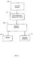
- the shredder 10includes a thickness detector 100 to detect overly thick stacks of documents or other articles that could jam the shredder mechanism 16, and communicate such detection to a controller 200, as shown in FIG. 4 .
- the shredder 10also includes a sensor 175 for sensing a performance characteristic of the motor 18.
- This sensor 175may be a motor temperature sensor 175 to detect the temperature of the motor and/or a motor current sensor 175 to detect the current drawn by the motor.
- This sensor 175communicates such detection to the controller 200, as shown in FIG. 4 .
- the detected performance characteristicis used to adjust the shredder capability.
- the motor 18may lose its efficiency and may cause the shredder 10 to shred fewer sheets per pass.
- the predetermined maximum thickness thresholdcan be reduced to reflect the loss in shredder capability over time.
- the controller 200may be configured to reduce the predetermined maximum thickness threshold based on the increase in temperature.
- the controller 200may be configured to sample and store motor temperatures during multiple uses and take an average of those to exclude any abnormal detections (such as if the user inserts something that entirely jams the shredder mechanism).
- the detected temperatureis derived, it can be compared to a threshold temperature, and if that detected temperature exceeds that threshold, the predetermined maximum thickness threshold can be reduced by a predetermined value (e.g., 5%).
- a predetermined valuee.g., 5%
- This processcan be repeated over time as needed to extend the shredder's useful life and reduce the risk of early motor burnout.
- the same adjustmentcan be made for the flutter threshold as well (or if the flutter threshold is set as a percentage of detected thickness at the outset of shredding on the predetermined maximum thickness, it need not be reduced, as it will be less of an issue since the predetermined maximum thickness threshold is being reduced).
- a straightforward comparisonmay be used for these reductions, as discussed above, or more a complex algorithm or a look-up table may be used.
- the current flowing through the motormay be the performance characteristic monitored.
- the current flowis inversely proportional to the motor's resistance, and thus a decrease in current flow means the motor is encountering more resistance.
- the same process used with the motor temperaturewould be used with current flow, except that the comparison would look for current flow decreasing below a threshold.
- any other performance characteristicmay be monitored, and those noted above are not intended to be limiting. These characteristics may also be used to trigger oiling/maintenance operations, as taught in U.S. Patent Publications No. 2006-0219827 . And the method of adjusting the predetermined maximum thickness threshold may be delayed until the performance characteristic has been sustained for long enough to indicate the maintenance/oiling has not improved performance. That is, if the performance characteristic has reached its threshold, the controller 200 may initially signal the user via an indicator that maintenance (e.g., oiling) is required.
- maintenancee.g., oiling
- the controller 200determines that maintenance has been performed (such as by the user pressing an input to indicate that, or because the controller triggered an automatic maintenance, such as oiling), or if a large enough period of time has passed, and the performance characteristic has still reached the threshold, the predetermined maximum thickness will then be reduced.
- the controller 200Upon detecting that the document(s) inserted exceed the predetermined maximum thickness threshold, the controller 200 communicates with an indicator 110 that provides a warning signal to the user, such as an audible signal and/or a visual signal.
- audible signalsinclude, but are not limited to beeping, buzzing, and/or any other type of signal that will alert the user that the stack of documents or other article that is about to be shredded is above a predetermined maximum thickness threshold and may cause the shredder mechanism 16 to jam. This gives the user the opportunity to reduce the thickness of the stack of documents or reconsider forcing the thick article through the shredder, knowing that any such forcing may jam and/or damage the shredder.
- a visual signalmay be provided in the form of a red warning light, which may be emitted from an LED. It is also contemplated that a green light may also be provided to indicate that the shredder 10 is ready to operate.
- the indicator 110is a progressive indication system that includes a series of indicators in the form of lights to indicate the thickness of the stack of documents or other article relative to the capacity of the shredder is provided, as illustrated in FIG. 5 . As illustrated, the progressive indication system includes a green light 112, a plurality of yellow lights 114, and a red light 116. The green light 112 indicates that the detected thickness of the item (e.g.
- the yellow lights 114provide a progressive indication of the thickness of the item.
- the first yellow light 114located next to the green light 112, would be triggered when the detected thickness is at or above the first predetermined thickness, but below a second predetermined thickness that triggers the red light 116. If there is more than one yellow light 114, each additional yellow light 114 may correspond to thicknesses at or above a corresponding number of predetermined thicknesses between the first and second predetermined thicknesses.
- the yellow lights 114may be used to train the user into getting a feel for how many documents should be shredded at one time.
- the red light 116indicates that the detected thickness is at or above the second predetermined thickness, which may be the same as the predetermined maximum thickness threshold, thereby warning the user that this thickness has been reached.
- the sequence of lightsmay be varied and their usage may vary. For example, they may be arranged linearly in a sequence as shown, or in other configurations (e.g. in a partial circle so that they appear like a fuel gauge or speedometer. Also, for example, the yellow light(s) 114 may be lit only for thickness(es) close to (i.e., within 25% of) the predetermined maximum thickness threshold, which triggers the red light 116. This is a useful sequence because of most people's familiarity with traffic lights. Likewise, a plurality of green lights (or any other color) could be used to progressively indicate the detected thickness within a range. Each light would be activated upon the detected thickness being equal to or greater than a corresponding predetermined thickness.
- a red (or other color) lightmay be used at the end of the sequence of lights to emphasize that the predetermined maximum thickness threshold has been reached or exceeded (or other ways of getting the user's attention may be used, such as emitting an audible signal, flashing all of the lights in the sequence, etc.). These alert features may be used in lieu of or in conjunction with cutting off power to the shredder mechanism upon detecting that the predetermined maximum thickness threshold has been reached or exceeded.
- the aforementioned indicators of the progressive indicator systemmay be in the form of audible signals, rather than visual signals or lights.
- audible signalsmay be used to provide a progressive indication of the thickness of the item.
- the audible signalsmay vary by number, frequency, pitch, and/or volume in such a way that provides the user with an indication of how close the detected thickness of the article is to the predetermined maximum thickness threshold. For example, no signal or a single "beep" may be provided when the detected thickness is well below the predetermined maximum thickness threshold, and a series of "beeps" that increase in number (e.g. more "beeps" the closer the detection is to the predetermined maximum thickness threshold) and/or frequency (e.g.
- the series of "beeps"may be continuous, thereby indicating to the user that such a threshold has been met and that the thickness of the article to be shredded should be reduced.
- the visual and audible signalsmay be used together in a single device.
- other ways of indicating progressive thicknesses of the items inserted in the throat 36may be used.
- an LCD screen with a bar graph that increases as the detected thickness increasesmay be used.
- a "fuel gauge,” i.e., a dial with a pivoting needle moving progressively between zero and a maximum desired thicknessmay also be used.
- the number or frequency of the intermittent audible noisesmay increase along with the detected thickness.
- the inventionis not limited to the indicators described herein, and other progressive (i.e., corresponding to multiple predetermined thickness levels) or binary (i.e., corresponding to a single predetermined thickness) indicators may be used.
- the aforementioned predetermined thicknessesmay be determined as follows. First, because the actual maximum thickness that the shredder mechanism may handle will depend on the material that makes up the item to be shredded, the maximum thickness may correspond to the thickness of the toughest article expected to be inserted into the shredder, such as a compact disc, which is made from polycarbonate. If it is known that the shredder mechanism may only be able to handle one compact disc at a time, the predetermined maximum thickness may be set to the standard thickness of a compact disc (i.e., 1.2 mm). It is estimated that such a thickness would also correspond to about 12 sheets of 20 1b. paper. Second, a margin for error may also be factored in.
- the predetermined maximum thicknessmay be set to a higher thickness, such as to 1.5 mm, which would allow for approximately an additional 3 sheets of paper to be safely inserted into the shredder (but not an additional compact disc).
- a higher thicknesssuch as to 1.5 mm, which would allow for approximately an additional 3 sheets of paper to be safely inserted into the shredder (but not an additional compact disc).
- these examplesare not intended to be limiting in any way.
- a detector 100may be provided to each of the throats and configured for different predetermined maximum thicknesses thresholds.
- the same shredder mechanismmay be able to handle one compact disc and 18 sheets of 20 lb paper.
- the predetermined maximum thickness threshold associated with the detector associated with the throat that is specifically designed to receive compact discsmay be set to about 1.5 mm (0.3 mm above the standard thickness of a compact disc), while the predetermined maximum thickness threshold associated with the detector associated with the throat that is specifically designed to receive sheets of paper may be set to about 1.8 mm.
- these examplesare not intended to be limiting in any way and are only given to illustrate features of embodiments of the invention. Further details of various thickness sensors and indicators may be found in the assignee's applications incorporated above.
- a selector switchmay optionally be provided on the shredder to allow the user to indicate what type of material is about to be shredded, and, hence the appropriate predetermined maximum thickness threshold for the detector.
- a given shredder mechanismmay be able to handle different maximum thicknesses for different types of materials, and the use of this selector switch allows the controller to use a different predetermined thickness for the material selected. For example, there may be a setting for "paper,” “compact discs,” and/or "credit cards,” as these materials are known to have different cutting characteristics and are popular items to shred for security reasons.
- the appropriate predetermined maximum thicknesses thresholdmay be set based on the known thicknesses of the items to be shredded, whether it is the thickness of a single compact disc or credit card, or the thickness of a predetermined number of sheets of paper of a known weight, such as 20 1b
- the selector switchis an optional feature, and the description thereof should not be considered to be limiting in any way.
- the detector 100is in communication with the motor 18 that powers the shredder mechanism 16 via the controller 200.
- the controller 200controls whether power is provided to the motor 18 so that the shafts 20 may rotate the cutter elements 19 and shred the item. This way, if the thickness of the item to be shredded is detected to be greater than the capacity of the shredder mechanism 16, power will not be provided to the shredder mechanism 16, thereby making the shredder 10 temporarily inoperable. This not only protects the motor 18 from overload, it also provides an additional safety feature so that items that should not be placed in the shredder 10 are not able to pass through the shredder mechanism 16, even though they may fit in the throat 36 of the shredder 10.
- FIGS. 6-8illustrate a method 300 for detecting the thickness of an item, e.g. a stack of documents or an article, being fed into the throat 36 of the shredder 10.
- the methodstarts at 302 by powering on the shredder 10, which the user may perform by connecting the shredder to a power supply and/or actuating its on/off switch.
- the operation of the controller 200branches out to 304 and to 402.
- the controller 200controls the method 300 by proceeding to 304 ( FIG. 6 ) and controls method 400 by proceeding to 402 ( FIG. 9 ).
- the controller 200runs the method 300 and the method 400 concurrently. Such concurrent operation may be parallel, repeatedly alternating series, etc.
- the controller 200determines whether the infrared sensor 150 is clear of articles. If the controller 200 determines that the infrared sensor 150 is clear of articles, the controller 200 zeroes the sensor at 306.
- the zero position of the sensoris defined as the position the sensor assumes when the shredder 10 is powered on without an article being inserted into the throat 36 of the shredder 10. The thickness of the article is measured with respect to the zero position of the sensor. Therefore, zeroing the sensor ensures that the thickness of the article is measured accurately.
- the controller 200determines that the infrared sensor 150 is not clear of articles, the controller 200 proceeds to block 308 and operates the motor 18 in a reverse direction for a short period of time so as to clear articles from the throat 36 of the shredder 10. After operating the motor in reverse, the method 300 may proceed to block 310. Although it would be preferable to zero the sensor at block 306 first, it is possible that a user may insist on leaving an article in the throat even after auto-reversing, expecting to force it to be shredded. To avoid an erroneous zeroing that would be caused by the presence of an article, the zeroing can be skipped, and the last zeroing of the sensor can be used. As an alternative, the reversing in block 308 could run for a set period of time, and then the method 300 could wait to proceed until the infrared sensor 150 has been cleared, thereafter proceeding to zeroing the sensor in block 306.
- the method 300proceeds to 310 where the motor 18 is turned off and not operating.
- the controller 200performs optional diagnostic tests to detect any faults in the shredder 10. Examples of the tests include, but are not limited to reading current across the motor 18, reading temperature of the motor 18 and checking whether the waste container 12 of the shredder 10 is full. If a fault is detected in the aforementioned tests, the controller 200 may turn on a warning signal to the user, such as an audible signal and/or a visual signal, at 316. Examples of audible signals include, but are not limited to beeping, buzzing, and/or any other type of signal that will alert the user that a fault is detected in the shredder 10. A visual signal may be provided in the form of a red warning light, which may be emitted from an LED. If a fault is not detected in the aforementioned tests, the motor 18 is ready for shredding the at least one article.
- the controller 200determines whether the thickness that has been detected is at least a predetermined maximum thickness threshold.
- the predetermined maximum thickness thresholdmay be based on the capacity of the shredder mechanism 16, as discussed above. If the controller 200 determines that the thickness that has been detected is at least the predetermined maximum thickness threshold, the method 300 returns to 310, where the motor stays off and then the controller 200 performs the tests at 312, and so on. As an option, the controller 200 may also actuate an indicator to alert the user that the article is too thick. This is beneficial, as it provides feedback to the user. Any of the indicators discussed above, or any other indicator, may be used for this purpose. If the controller 200 determines that the thickness that has been detected is less than the predetermined maximum thickness threshold, the method 300 proceeds to block 320 ( FIG. 7 ).
- the methodproceeds to 322. If the infrared sensor 150 does not detect the at least one article, the method returns to 310, the controller 200 performs tests at 312, and so on. At 322, the controller 200 sets a flutter threshold, which is higher than the predetermined maximum thickness threshold. During the shredding operation, the trailing portion of the at least one article inserted into the throat 36 of the shredder 10 tends to flutter or wave back and forth. The measured or detected thickness of the fluttering article may be more than the actual thickness of the at least one article, as the thickness detector may be moved by the flutter of the article.
- a flutter thresholdthat is higher than the predetermined maximum thickness threshold is set.
- the flutter thresholdmay be a fixed percentage or value higher than the predetermined maximum thickness threshold. The flutter threshold provides an additional tolerance to the thickness of the article, thus preventing the motor from shutting off unnecessarily when the trailing portion of the at least one article flutters.
- the controller 200operates the motor 18 in a forward shredding direction.
- a delayis incorporated at 326.
- a severe flutter or bendingmay develop in the article while the user is inserting the article into the throat 36 of the shredder 10. The delay provides a chance for the at least one article to be completely released by the user and allow the fluttering of at least one article to wane to some extent.
- a change in the thickness sensor readingsmay be monitored to determine whether the change in the thickness is due to a paper wrinkle or a paper fold (as can happen if the paper is fed into the throat at an angle to the proper feeding direction) or due to an insertion of an additional article in the throat after the shredding has started. This is done by filtering the input and determining whether the change in the thickness reading is rapid and hard as would be the case when an additional article is inserted, or slow and soft as would be the case when a wrinkle is developed over the time during the shred cycle. To differentiate between the two situations, the controller 200 monitors a rate of change in the detected thickness. If the rate is above a rate threshold, this generally indicates that an additional article has been inserted; and likewise if the rate is below a rate threshold, this generally indicates that the thickness change is attributable to the formation of a wrinkle or fold.
- the controller 200determines whether the thickness that has been detected is at least or exceeds the flutter threshold, and optionally whether it is attributable to the insertion of an additional article or the development of a wrinkle or fold (i.e., by monitoring the rate of thickness change and comparing it to the rate threshold). If the controller 200 determines that the thickness that has been detected is less than the flutter threshold or it exceeds the flutter threshold but the rate of thickness change is below the rate threshold (and most likely a fold or wrinkle), the method 300 proceeds to step 329, where the infrared sensor 150 is again checked for presence of the article. If the article is still present at the infrared sensor 150, the method 300 return to 328. If not, the method 300 proceeds to a delay sufficient to allow the shredding process to be completed (usually 3-5 seconds) at 331, and then to stopping the motor at 310.
- the controller 200determines that the thickness that has been detected is at least or exceeds the flutter threshold and the rate of thickness change is at or above the rate threshold (likely the result of an additional article being inserted in the throat of the shredder 10), the controller 200 prevents the motor 18 from driving the cutter elements 19 at 330.
- the controller 200may turn on a warning signal to the user at 332.
- the warming signalmay include an audible signal and/or a visual signal. Examples of audible signals include, but are not limited to beeping, buzzing, and/or any other type of signal that will alert the user.
- a visual signalmay be provided in the form of a red warning light, which may be emitted from an LED. Any indicator discussed above, or any other suitable indicator, may be used.
- the controller 200determines whether the thickness that has been detected is reduced to below the flutter threshold. If the controller 200 determines that the thickness that has been detected is less than the flutter threshold (e.g., the user has removed the additional inserted item), the method 300 proceeds to step 324, where the controller 200 operates the motor 18 in a forward shredding direction. If the controller 200 determines that the thickness that has been detected is still not less than the flutter threshold, the method 300 proceeds to step 332, where the controller 200 continues to provide the above mentioned warning signal to the user.
- FIG. 8shows an alternative logic where there is no discrimination based on the rate of thickness changes.
- the acts in FIG. 8take the place of block 333 in FIG. 7 , and block 328 in FIG. 7 simply determines whether the detected thickness exceeds the flutter threshold. If the detected thickness exceeds the flutter threshold, this alternative logic proceeds through blocks 330 and 332 to block 334 (and if the detected thickness does exceeds the flutter threshold, it proceeds to block 329 as shown in FIG. 7 ).
- the controller 200starts a timer, which is set to a preset period of time. The delay provided by the timer gives the user an opportunity to remove any excess paper.
- the controller 200determines whether the detected thickness is at least or exceeds the flutter threshold (e.g., has the user removed the excess paper). When the controller 200 determines that the detected thickness has been reduced below the flutter threshold, the method 300 proceeds back to 324 and restarts the motor 18. If the controller 200 determines that the thickness still is equal to or exceeds the flutter threshold (e.g., by the excess paper not having been removed), then the controller 200 determines whether the timer has expired at 338. If the controller 200 determines that the timer has expired, the method continues to 340. If the controller 200 determines that the timer has not expired, the method returns to 336, and so on until the timer does expire (or the thickness is reduced below the flutter threshold).
- the controller 200determines whether the detected thickness is at least or exceeds the flutter threshold (e.g., has the user removed the excess paper).
- the controller 200After the timer has expired and the excess paper is still not removed, at 340, the controller 200, by assuming that the user wants to force the shredding operation, increases the flutter threshold to higher value than the prior set flutter threshold, thereby allowing the articles to pass through the cutter elements 19.
- the method 300then proceeds to 342.
- the motor 18operates to drive the cutter elements 19 so that the cutter elements 19 shred the articles fed into the throat 36 of the shredder 10. Then, the method returns to block 328 where the increased flutter threshold is used for the remainder of the process.
- the methodcould simply ignore whether the flutter threshold is exceeded, and just proceed to operate the motor 18 to complete the shredding operation.
- the sensors located on the motor 18can monitor the motor operating conditions (e.g., the temperature of the motor, the current flowing through the motor, etc) so that the controller 200 can stop the motor if it is overloaded by too many articles being shredded in a conventional manner.
- the controller 200will still determine whether infrared is clear of articles. If the controller 200 determines that the infrared is clear of articles, the method 300 returns to 310, and the controller 200 performs the tests at 312, and so on. If the controller 200 determines that the infrared is not clear of articles, the method 300 keeps operating the motor 18, and the controller determines whether the infrared is clear of articles, and so on.
- FIG. 9shows an indicator control method 400 that operates simultaneously to the method 300.
- This method 400updates the progressive indicator system and provides the user of the shredder an indication of the detected thickness. The user has an option to turn off the thickness sensing functionality of the shredder. Therefore, at 402, the controller 200 determines whether the jam proof system is turned on. If the controller 200 determines that the jam proof system is turned on, the controller 200 detects the thickness of the article fed into the throat 36 of the shredder 10. If the controller 200 determines that the jam proof system is turned off, the method 400 returns to 402.
- the controller 200determines whether the position of the sensor is less than the zero position as described above. If the controller 200 determines that the position of the sensor is less than the zero position, the controller 200 zeroes the sensor at 408. After zeroing the sensor, the method 400 proceeds to 410 where the controller 200 updates the progressive indicator system. If the controller 200 determines that the position of the sensor is not less than the zero point, the controller 200 updates the progressive indicator system at 410. The method 400 proceeds to 412 after updating the progressive indicator system based on the detected thickness. A delay is incorporated at 412. The method 400 returns to 402 after the delay, the controller 200 detects the thickness at 404 and so on. The illustrated methods are not intended to be limiting in any way.
- the controller 200may cause the red light 116 to illuminate and/or causes an audible signal to sound. If the controller 200 determines that the thickness that has been detected is less than the predetermined maximum thickness threshold, the controller 200 may cause the green light 112 to illuminate. In the embodiment that includes the plurality of yellow lights 114 as part of the indicator 100, if the controller 200 determines that the thickness that has been detected is less than the predetermined maximum thickness threshold, but close to or about the predetermined maximum thickness threshold, the controller 200 may cause one of the yellow lights to illuminate, depending on how close to the predetermined maximum thickness threshold the detected thickness is.
- the different yellow lightsmay represent increments of about 0.1 mm so that if the detected thickness is within 0.1 mm of the predetermined maximum thickness threshold, the yellow light 114 that is closest to the red light 116 illuminates, and so on. The user will be warned that the particular thickness is very close to the capacity limit of the shredder 10.
- any increment of thicknessmay be used to cause a particular yellow light to illuminate. The example given should not be considered to be limiting in any way.
Landscapes
- Engineering & Computer Science (AREA)
- Food Science & Technology (AREA)
- Crushing And Pulverization Processes (AREA)
- Crushing And Grinding (AREA)
- Processing And Handling Of Plastics And Other Materials For Molding In General (AREA)
Abstract
Description
- The present invention relates to shredders for destroying articles, such as documents, compact discs, etc.
- Shredders are well known devices for destroying articles, such as paper, documents, compact discs ("CDs"), expired credit cards, etc. Typically, users purchase shredders to destroy sensitive information bearing articles, such as credit card statements with account information, documents containing company trade secrets, etc.
- A common type of shredder, see for example
WO 2007/109753 has a shredder mechanism contained within a housing that is removably mounted atop a container. The shredder mechanism typically has a series of cutter elements that shred articles fed therein and discharge the shredded articles downwardly into the container. The shredder typically has a stated capacity, such as the number of sheets of paper (typically of 20 lb. weight) that may be shredded at one time; however, the feed throat of a typical shredder can receive more sheets of paper than the stated capacity. This is typically done to make feeding easier. A common frustration of users of shredders is to feed too many papers into the feed throat, only to have the shredder jam after it has started to shred the papers. To free the shredder of the papers, the user typically reverses the direction of rotation of the cutter elements via a switch until the papers become free. Occasionally, the jamming may be so severe that reversing may not free the paper and the paper must be pulled out manually, which is very difficult with the paper bound between the blades. - The assignee of the present application, Fellowes, Inc., has developed thickness sensing technologies for shredders. By sensing thickness of the articles being fed, the shredder can be stopped (or not started) before a jam occurs. See
U.S. Patent Publication Nos. 2006-0219827 A1 and2006-0054725 A1 , andU.S. Application No. 11/385,864 - A competitive shredder from Rexel also has a thickness sensor that stops the shredder upon sensing article thickness being over a certain threshold. A light is also illuminated to alert the user. Rexel uses the name Mercury Technology to refer to its thickness sensing feature. Seewww.rexelshredders.co.uk. To the best of applicants knowledge it is believed that this shredder was first disclosed on that website in January or February 2007.
- No admission is made as to whether the foregoing thickness sensing technologies constitute prior art.
- It is an object of the invention to provide a shredder and a method for operating a shredder that does not jam as a result of too many papers, or an article that is too thick, being fed into the shredder.
- The object of the invention has been achieved with a shredder according to the claims.
- The object of the invention has been also achieved with a method according to claims.
- Other aspects, features, and advantages of the present invention will become apparent from the following detailed description, the accompanying drawings, and the appended claims.
FIG. 1 is a perspective view of a shredder constructed in accordance with an embodiment of the present invention;FIG. 2 is an exploded perspective view of the shredder ofFIG. 1 ;FIG. 3 is a schematic illustration of an embodiment of a detector configured to detect a thickness of a article to be shredded by the shredder.FIG. 4 is a schematic illustration of interaction between a controller and other parts of the shredder;FIG. 5 is a schematic illustration of an embodiment of an indicator located on the shredder;FIG. 6 is a flow diagram of an embodiment of a method for shredding an article;FIG. 7 is a flow diagram of an embodiment of a method for shredding an article;FIG. 8 is a flow diagram of an embodiment of a method for shredding an article; andFIG. 9 is a flow diagram of an embodiment of a method for shredding an article.FIGS. 1 and2 illustrate a shredder constructed in accordance with an embodiment of the present invention. The shredder is generally indicated at 10. In the illustrated embodiment, theshredder 10 sits atop a waste container, generally indicated at 12, which is formed of molded plastic or any other material. Theshredder 10 illustrated is designed specifically for use with thecontainer 12, as theshredder housing 14 sits on the upper periphery of thewaste container 12 in a nested relation. However, theshredder 10 may also be designed so as to sit atop a wide variety of standard waste containers, and theshredder 10 would not be sold with the container. Likewise, theshredder 10 could be part of a large freestanding housing, and a waste container would be enclosed in the housing. An access door would provide for access to and removal of the container. Generally speaking, theshredder 10 may have any suitable construction or configuration and the illustrated embodiment is not intended to be limiting in any way. In addition, the term "shredder" is not intended to be limited to devices that literally "shred" documents and articles, but is instead intended to cover any device that destroys documents and articles in a manner that leaves each document or article illegible and/or useless.- As shown in
FIG. 2 , in an embodiment, theshredder 10 includes ashredder mechanism 16 that includes an electrically poweredmotor 18 and a plurality ofcutter elements 19. "Shredder mechanism" is a generic structural term to denote a device that destroys articles using at least one cutter element. Such destroying may be done in any particular way. For example, the shredder mechanism may include at least one cutter element that is configured to punch a plurality of holes in the document or article in a manner that destroys the document or article. In the illustrated embodiment, thecutter elements 19 are generally mounted on a pair of parallel rotatingshafts 20. Themotor 18 operates using electrical power to rotatably drive the shafts and the cutter elements through aconventional transmission 23 so that the cutter elements shred articles fed therein. Theshredder mechanism 16 may also include asub-frame 21 for mounting the shafts, themotor 18, and thetransmission 23. The operation and construction of such ashredder mechanism 16 are well known and need not be described herein in detail. Generally, anysuitable shredder mechanism 16 known in the art or developed hereafter may be used. - The
shredder 10 also includes theshredder housing 14, mentioned above. Theshredder housing 14 includestop wall 24 that sits atop thecontainer 12. Thetop wall 24 is molded from plastic and an opening 26 is located at a front portion thereof. The opening 26 is formed in part by a downwardly depending generally U-shapedmember 28. The U-shapedmember 28 has a pair of spaced apartconnector portions 27 on opposing sides thereof and ahand grip portion 28 extending between theconnector portions 27 in spaced apart relation from thehousing 14. Theopening 26 allows waste to be discarded into thecontainer 12 without being passed through theshredder mechanism 16, and themember 28 may act as a handle for carrying theshredder 10 separate from thecontainer 12. As an optional feature, this opening 26 may be provided with a lid, such as a pivoting lid, that opens and closes the opening 26. However, this opening in general is optional and may be omitted entirely. Moreover, the shredder housing 14 and itstop wall 24 may have any suitable construction or configuration. - The
shredder housing 14 also includes abottom receptacle 30 having a bottom wall, four side walls and an open top. Theshredder mechanism 16 is received therein, and thereceptacle 30 is affixed to the underside of thetop wall 24 by fasteners. Thereceptacle 30 has anopening 32 in its bottom wall through which theshredder mechanism 16 discharges shredded articles into thecontainer 12. - The
top wall 24 has a generally laterally extending opening, which is often referred to as athroat 36, extending generally parallel and above the cutter elements. Thethroat 36 enables the articles being shredded to be fed into the cutter elements. As can be appreciated, thethroat 36 is relatively narrow, which is desirable for preventing overly thick items, such as large stacks of documents, from being fed into cutter elements, which could lead to jamming. Thethroat 36 may have any configuration. - The
top wall 24 also has aswitch recess 38 with an opening therethrough. An on/offswitch 42 includes a switch module (not shown) mounted to thetop wall 24 underneath therecess 38 by fasteners, and a manuallyengageable portion 46 that moves laterally within therecess 38. The switch module has a movable element (not shown) that connects to the manuallyengageable portion 46 through the opening. This enables movement of the manuallyengageable portion 46 to move the switch module between its states. - In the illustrated embodiment, the switch module connects the
motor 18 to the power supply. This connection may be direct or indirect, such as via a controller. Typically, the power supply will be astandard power cord 44 with aplug 48 on its end that plugs into a standard AC outlet. Theswitch 42 is movable between an on position and an off position by moving theportion 46 laterally within therecess 38. In the on position, contacts in the switch module are closed by movement of the manuallyengageable portion 46 and the movable element to enable a delivery of electrical power to themotor 18. In the off position, contacts in the switch module are opened to disable the delivery of electric power to themotor 18. Alternatively, the switch may be coupled to a controller, which in turn controls a relay switch, triac etc. for controlling the flow of electricity to themotor 18. - As an option, the
switch 42 may also have a reverse position wherein contacts are closed to enable delivery of electrical power to operate themotor 18 in a reverse manner. This would be done by using a reversible motor and applying a current that is of a reverse polarity relative to the on position. The capability to operate themotor 18 in a reversing manner is desirable to move the cutter elements in a reversing direction for clearing jams. In the illustrated embodiment, in the off position the manuallyengageable portion 46 and the movable element would be located generally in the center of therecess 38, and the on and reverse positions would be on opposing lateral sides of the off position. - Generally, the construction and operation of the
switch 42 for controlling themotor 42 are well known and any construction for such aswitch 42 may be used. For example, the switch need not be mechanical and could be of the electro-sensitive type described inU.S. Patent Application No. 11/536,145 .
Likewise, such as switch may be entirely omitted, and the shredder can be started based on insertion of an article to be shredded. - In the illustrated embodiment, the
top cover 24 also includes anotherrecess 50 associated with anoptional switch lock 52. Theswitch lock 52 includes a manuallyengageable portion 54 that is movable by a user's hand and a locking portion (not shown). The manuallyengageable portion 54 is seated in therecess 50 and the locking portion is located beneath thetop wall 24. The locking portion is integrally formed as a plastic piece with the manuallyengageable portion 54 and extends beneath thetop wall 24 via an opening formed in therecess 50. - The
switch lock 52 causes theswitch 42 to move from either its on position or reverse position to its off position by a camming action as theswitch lock 52 is moved from a releasing position to a locking position. In the releasing position, the locking portion is disengaged from the movable element of theswitch 42, thus enabling theswitch 42 to be moved between its on, off, and reverse positions. In the locking position, the movable element of theswitch 42 is restrained in its off position against movement to either its on or reverse position by the locking portion of theswitch lock 52. - Preferably, but not necessarily, the manually
engageable portion 54 of theswitch lock 52 has an upwardly extendingprojection 56 for facilitating movement of theswitch lock 52 between the locking and releasing positions. - One advantage of the
switch lock 52 is that, by holding theswitch 42 in the off position, to activate theshredder mechanism 16 theswitch lock 52 must first be moved to its releasing position, and then theswitch 42 is moved to its on or reverse position. This reduces the likelihood of theshredder mechanism 16 being activated unintentionally. Reference may be made toU.S. Patent No.7,040,559 B2 ., for further details of theswitch lock 52. This switch lock is an entirely optional feature and may be omitted. - In the illustrated embodiment, the
shredder housing 14 is designed specifically for use with thecontainer 12 and it is intended to sell them together. The upperperipheral edge 60 of thecontainer 12 defines an upwardly facingopening 62, and provides aseat 61 on which theshredder 10 is removably mounted. Theseat 61 includes a pair of pivot guides 64 provided on opposing lateral sides thereof. The pivot guides 64 include upwardly facingrecesses 66 that are defined by walls extending laterally outwardly from theupper edge 60 of thecontainer 12. The walls defining therecesses 66 are molded integrally from plastic with thecontainer 12, but may be provided as separate structures and formed from any other material. At the bottom of eachrecess 66 is provided a step down or ledge providing a generallyvertical engagement surface 68. This step down or ledge is created by two sections of therecesses 66 being provided with different radii. Reference may be made toU.S. Pat. No. 7,025,293 , for further details of the pivotal mounting. This pivotal mounting is entirely optional and may be omitted. FIG. 3 shows adetector 100 used to detect the thickness of an article (e.g., a compact disc, credit card, stack of paper, etc.) that is placed in thethroat 36 of theshredder 10. As shown inFIG. 3 , thedetector 100 may include anoptical sensor 140. Thedetector 100 is located above aninfrared sensor 150 that detects the presence of an article. Of course, any such sensor may be used. The illustrated embodiment is not intended to be limiting in any way. Thesensor 150 provides a signal to thecontroller 200, which in turn is communicated to themotor 18. When theinfrared sensor 150 senses that an article is passing through a lower portion of thethroat 36, thecontroller 200 signals themotor 18 to start turning theshafts 20 andcutter elements 19. Of course, because thedetector 100 is also in communication with thecontroller 200, if thedetector 100 detects that the thickness of the article that has entered the throat is too thick for the capacity of the shredder mechanism 16 (i.e., above a predetermined maximum thickness threshold), theshredder mechanism 16 may not operate, even though theinfrared sensor 150 has detected the presence of an article. Of course, this particular configuration is not intended to be limiting in any way.- In an embodiment of the invention, the
shredder 10 includes athickness detector 100 to detect overly thick stacks of documents or other articles that could jam theshredder mechanism 16, and communicate such detection to acontroller 200, as shown inFIG. 4 . In addition to thethickness detector 100, theshredder 10 also includes asensor 175 for sensing a performance characteristic of themotor 18. Thissensor 175 may be amotor temperature sensor 175 to detect the temperature of the motor and/or a motorcurrent sensor 175 to detect the current drawn by the motor. Thissensor 175 communicates such detection to thecontroller 200, as shown inFIG. 4 . The detected performance characteristic is used to adjust the shredder capability. Specifically, during long-term use of theshredder 10, themotor 18 may lose its efficiency and may cause theshredder 10 to shred fewer sheets per pass. Thus, by monitoring the performance characteristic, the predetermined maximum thickness threshold can be reduced to reflect the loss in shredder capability over time. - For example, if the performance characteristic monitored is temperature, an increase in operating temperature of the
motor 18 is indicative that its performance is declining. And thus, thecontroller 200 may be configured to reduce the predetermined maximum thickness threshold based on the increase in temperature. Thecontroller 200 may be configured to sample and store motor temperatures during multiple uses and take an average of those to exclude any abnormal detections (such as if the user inserts something that entirely jams the shredder mechanism). However the detected temperature is derived, it can be compared to a threshold temperature, and if that detected temperature exceeds that threshold, the predetermined maximum thickness threshold can be reduced by a predetermined value (e.g., 5%). For example, the prior predetermined maximum thickness threshold stored in memory can be erased, and the reduced threshold can be stored in the controller memory in its place. This process can be repeated over time as needed to extend the shredder's useful life and reduce the risk of early motor burnout. The same adjustment can be made for the flutter threshold as well (or if the flutter threshold is set as a percentage of detected thickness at the outset of shredding on the predetermined maximum thickness, it need not be reduced, as it will be less of an issue since the predetermined maximum thickness threshold is being reduced). A straightforward comparison may be used for these reductions, as discussed above, or more a complex algorithm or a look-up table may be used. - Likewise, the current flowing through the motor may be the performance characteristic monitored. The current flow is inversely proportional to the motor's resistance, and thus a decrease in current flow means the motor is encountering more resistance. The same process used with the motor temperature would be used with current flow, except that the comparison would look for current flow decreasing below a threshold.
- Any other performance characteristic may be monitored, and those noted above are not intended to be limiting. These characteristics may also be used to trigger oiling/maintenance operations, as taught in
U.S. Patent Publications No. 2006-0219827 . And the method of adjusting the predetermined maximum thickness threshold may be delayed until the performance characteristic has been sustained for long enough to indicate the maintenance/oiling has not improved performance. That is, if the performance characteristic has reached its threshold, thecontroller 200 may initially signal the user via an indicator that maintenance (e.g., oiling) is required. If thecontroller 200 determines that maintenance has been performed (such as by the user pressing an input to indicate that, or because the controller triggered an automatic maintenance, such as oiling), or if a large enough period of time has passed, and the performance characteristic has still reached the threshold, the predetermined maximum thickness will then be reduced. - Upon detecting that the document(s) inserted exceed the predetermined maximum thickness threshold, the
controller 200 communicates with anindicator 110 that provides a warning signal to the user, such as an audible signal and/or a visual signal. Examples of audible signals include, but are not limited to beeping, buzzing, and/or any other type of signal that will alert the user that the stack of documents or other article that is about to be shredded is above a predetermined maximum thickness threshold and may cause theshredder mechanism 16 to jam. This gives the user the opportunity to reduce the thickness of the stack of documents or reconsider forcing the thick article through the shredder, knowing that any such forcing may jam and/or damage the shredder. - A visual signal may be provided in the form of a red warning light, which may be emitted from an LED. It is also contemplated that a green light may also be provided to indicate that the
shredder 10 is ready to operate. In an embodiment, theindicator 110 is a progressive indication system that includes a series of indicators in the form of lights to indicate the thickness of the stack of documents or other article relative to the capacity of the shredder is provided, as illustrated inFIG. 5 . As illustrated, the progressive indication system includes agreen light 112, a plurality ofyellow lights 114, and ared light 116. Thegreen light 112 indicates that the detected thickness of the item (e.g. a single paper, a stack of papers, a compact disc, a credit card, etc.) that has been placed in thethroat 36 of theshredder 10 is below a first predetermined thickness and well within the capacity of the shredder. Theyellow lights 114 provide a progressive indication of the thickness of the item. The firstyellow light 114, located next to thegreen light 112, would be triggered when the detected thickness is at or above the first predetermined thickness, but below a second predetermined thickness that triggers thered light 116. If there is more than oneyellow light 114, each additionalyellow light 114 may correspond to thicknesses at or above a corresponding number of predetermined thicknesses between the first and second predetermined thicknesses. Theyellow lights 114 may be used to train the user into getting a feel for how many documents should be shredded at one time. Thered light 116 indicates that the detected thickness is at or above the second predetermined thickness, which may be the same as the predetermined maximum thickness threshold, thereby warning the user that this thickness has been reached. - The sequence of lights may be varied and their usage may vary. For example, they may be arranged linearly in a sequence as shown, or in other configurations (e.g. in a partial circle so that they appear like a fuel gauge or speedometer. Also, for example, the yellow light(s) 114 may be lit only for thickness(es) close to (i.e., within 25% of) the predetermined maximum thickness threshold, which triggers the
red light 116. This is a useful sequence because of most people's familiarity with traffic lights. Likewise, a plurality of green lights (or any other color) could be used to progressively indicate the detected thickness within a range. Each light would be activated upon the detected thickness being equal to or greater than a corresponding predetermined thickness. A red (or other color) light may be used at the end of the sequence of lights to emphasize that the predetermined maximum thickness threshold has been reached or exceeded (or other ways of getting the user's attention may be used, such as emitting an audible signal, flashing all of the lights in the sequence, etc.). These alert features may be used in lieu of or in conjunction with cutting off power to the shredder mechanism upon detecting that the predetermined maximum thickness threshold has been reached or exceeded. - Similarly, the aforementioned indicators of the progressive indicator system may be in the form of audible signals, rather than visual signals or lights. For example, like the yellow lights described above, audible signals may be used to provide a progressive indication of the thickness of the item. The audible signals may vary by number, frequency, pitch, and/or volume in such a way that provides the user with an indication of how close the detected thickness of the article is to the predetermined maximum thickness threshold. For example, no signal or a single "beep" may be provided when the detected thickness is well below the predetermined maximum thickness threshold, and a series of "beeps" that increase in number (e.g. more "beeps" the closer the detection is to the predetermined maximum thickness threshold) and/or frequency (e.g. less time between beeps the closer the detection is to the predetermined maximum thickness threshold) as the detected thickness approaches the predetermined maximum thickness threshold may be provided. If the detected thickness is equal to or exceeds the predetermined maximum thickness threshold, the series of "beeps" may be continuous, thereby indicating to the user that such a threshold has been met and that the thickness of the article to be shredded should be reduced.
- The visual and audible signals may be used together in a single device. Also, other ways of indicating progressive thicknesses of the items inserted in the
throat 36 may be used. For example, an LCD screen with a bar graph that increases as the detected thickness increases may be used. Also, a "fuel gauge," i.e., a dial with a pivoting needle moving progressively between zero and a maximum desired thickness, may also be used. As discussed above, with an audible signal, the number or frequency of the intermittent audible noises may increase along with the detected thickness. The invention is not limited to the indicators described herein, and other progressive (i.e., corresponding to multiple predetermined thickness levels) or binary (i.e., corresponding to a single predetermined thickness) indicators may be used. - The aforementioned predetermined thicknesses may be determined as follows. First, because the actual maximum thickness that the shredder mechanism may handle will depend on the material that makes up the item to be shredded, the maximum thickness may correspond to the thickness of the toughest article expected to be inserted into the shredder, such as a compact disc, which is made from polycarbonate. If it is known that the shredder mechanism may only be able to handle one compact disc at a time, the predetermined maximum thickness may be set to the standard thickness of a compact disc (i.e., 1.2 mm). It is estimated that such a thickness would also correspond to about 12 sheets of 20 1b. paper. Second, a margin for error may also be factored in. For example in the example given, the predetermined maximum thickness may be set to a higher thickness, such as to 1.5 mm, which would allow for approximately an additional 3 sheets of paper to be safely inserted into the shredder (but not an additional compact disc). Of course, these examples are not intended to be limiting in any way.
- For shredders that include separate throats for receiving sheets of paper and compact discs and/or credit cards, a
detector 100 may be provided to each of the throats and configured for different predetermined maximum thicknesses thresholds. For example, the same shredder mechanism may be able to handle one compact disc and 18 sheets of 20 lb paper. Accordingly, the predetermined maximum thickness threshold associated with the detector associated with the throat that is specifically designed to receive compact discs may be set to about 1.5 mm (0.3 mm above the standard thickness of a compact disc), while the predetermined maximum thickness threshold associated with the detector associated with the throat that is specifically designed to receive sheets of paper may be set to about 1.8 mm. Of course, these examples are not intended to be limiting in any way and are only given to illustrate features of embodiments of the invention. Further details of various thickness sensors and indicators may be found in the assignee's applications incorporated above. - Similarly, a selector switch may optionally be provided on the shredder to allow the user to indicate what type of material is about to be shredded, and, hence the appropriate predetermined maximum thickness threshold for the detector. A given shredder mechanism may be able to handle different maximum thicknesses for different types of materials, and the use of this selector switch allows the controller to use a different predetermined thickness for the material selected. For example, there may be a setting for "paper," "compact discs," and/or "credit cards," as these materials are known to have different cutting characteristics and are popular items to shred for security reasons. Again, based on the capacity of the shredder mechanism, the appropriate predetermined maximum thicknesses threshold may be set based on the known thicknesses of the items to be shredded, whether it is the thickness of a single compact disc or credit card, or the thickness of a predetermined number of sheets of paper of a known weight, such as 20 1b The selector switch is an optional feature, and the description thereof should not be considered to be limiting in any way.
- Returning to
FIG. 4 , in addition to theindicator 110 discussed above, thedetector 100 is in communication with themotor 18 that powers theshredder mechanism 16 via thecontroller 200. Specifically, thecontroller 200 controls whether power is provided to themotor 18 so that theshafts 20 may rotate thecutter elements 19 and shred the item. This way, if the thickness of the item to be shredded is detected to be greater than the capacity of theshredder mechanism 16, power will not be provided to theshredder mechanism 16, thereby making theshredder 10 temporarily inoperable. This not only protects themotor 18 from overload, it also provides an additional safety feature so that items that should not be placed in theshredder 10 are not able to pass through theshredder mechanism 16, even though they may fit in thethroat 36 of theshredder 10. FIGS. 6-8 illustrate amethod 300 for detecting the thickness of an item, e.g. a stack of documents or an article, being fed into thethroat 36 of theshredder 10. The method starts at 302 by powering on theshredder 10, which the user may perform by connecting the shredder to a power supply and/or actuating its on/off switch. When theshredder 10 is powered on at 302, the operation of thecontroller 200 branches out to 304 and to 402. Thecontroller 200 controls themethod 300 by proceeding to 304 (FIG. 6 ) and controlsmethod 400 by proceeding to 402 (FIG. 9 ). Thus, thecontroller 200 runs themethod 300 and themethod 400 concurrently. Such concurrent operation may be parallel, repeatedly alternating series, etc.- At 304, the
controller 200 determines whether theinfrared sensor 150 is clear of articles. If thecontroller 200 determines that theinfrared sensor 150 is clear of articles, thecontroller 200 zeroes the sensor at 306. The zero position of the sensor is defined as the position the sensor assumes when theshredder 10 is powered on without an article being inserted into thethroat 36 of theshredder 10. The thickness of the article is measured with respect to the zero position of the sensor. Therefore, zeroing the sensor ensures that the thickness of the article is measured accurately. - If the
controller 200 determines that theinfrared sensor 150 is not clear of articles, thecontroller 200 proceeds to block 308 and operates themotor 18 in a reverse direction for a short period of time so as to clear articles from thethroat 36 of theshredder 10. After operating the motor in reverse, themethod 300 may proceed to block 310. Although it would be preferable to zero the sensor atblock 306 first, it is possible that a user may insist on leaving an article in the throat even after auto-reversing, expecting to force it to be shredded. To avoid an erroneous zeroing that would be caused by the presence of an article, the zeroing can be skipped, and the last zeroing of the sensor can be used. As an alternative, the reversing in block 308 could run for a set period of time, and then themethod 300 could wait to proceed until theinfrared sensor 150 has been cleared, thereafter proceeding to zeroing the sensor inblock 306. - After zeroing the sensor at 306, the
method 300 proceeds to 310 where themotor 18 is turned off and not operating. At 312, thecontroller 200 performs optional diagnostic tests to detect any faults in theshredder 10. Examples of the tests include, but are not limited to reading current across themotor 18, reading temperature of themotor 18 and checking whether thewaste container 12 of theshredder 10 is full. If a fault is detected in the aforementioned tests, thecontroller 200 may turn on a warning signal to the user, such as an audible signal and/or a visual signal, at 316. Examples of audible signals include, but are not limited to beeping, buzzing, and/or any other type of signal that will alert the user that a fault is detected in theshredder 10. A visual signal may be provided in the form of a red warning light, which may be emitted from an LED. If a fault is not detected in the aforementioned tests, themotor 18 is ready for shredding the at least one article. - At 314, at least one article is inserted into the
throat 36 of theshredder 10 by the user and thedetector 100 detects the thickness of the at least one article. At 318, thecontroller 200 determines whether the thickness that has been detected is at least a predetermined maximum thickness threshold. The predetermined maximum thickness threshold may be based on the capacity of theshredder mechanism 16, as discussed above. If thecontroller 200 determines that the thickness that has been detected is at least the predetermined maximum thickness threshold, themethod 300 returns to 310, where the motor stays off and then thecontroller 200 performs the tests at 312, and so on. As an option, thecontroller 200 may also actuate an indicator to alert the user that the article is too thick. This is beneficial, as it provides feedback to the user. Any of the indicators discussed above, or any other indicator, may be used for this purpose. If thecontroller 200 determines that the thickness that has been detected is less than the predetermined maximum thickness threshold, themethod 300 proceeds to block 320 (FIG. 7 ). - If the at least one article is detected by the
infrared sensor 150, the method proceeds to 322. If theinfrared sensor 150 does not detect the at least one article, the method returns to 310, thecontroller 200 performs tests at 312, and so on. At 322, thecontroller 200 sets a flutter threshold, which is higher than the predetermined maximum thickness threshold. During the shredding operation, the trailing portion of the at least one article inserted into thethroat 36 of theshredder 10 tends to flutter or wave back and forth. The measured or detected thickness of the fluttering article may be more than the actual thickness of the at least one article, as the thickness detector may be moved by the flutter of the article. This may exceed the predetermined maximum thickness threshold, and unnecessarily cause thecontroller 200 to shut off themotor 18 assuming that the measured thickness is same as the actual thickness. To prevent themotor 18 from unnecessarily shutting off, a flutter threshold that is higher than the predetermined maximum thickness threshold is set. For example, the flutter threshold may be a fixed percentage or value higher than the predetermined maximum thickness threshold. The flutter threshold provides an additional tolerance to the thickness of the article, thus preventing the motor from shutting off unnecessarily when the trailing portion of the at least one article flutters. - At 324, the
controller 200 operates themotor 18 in a forward shredding direction. A delay is incorporated at 326. A severe flutter or bending may develop in the article while the user is inserting the article into thethroat 36 of theshredder 10. The delay provides a chance for the at least one article to be completely released by the user and allow the fluttering of at least one article to wane to some extent. - As an option, a change in the thickness sensor readings may be monitored to determine whether the change in the thickness is due to a paper wrinkle or a paper fold (as can happen if the paper is fed into the throat at an angle to the proper feeding direction) or due to an insertion of an additional article in the throat after the shredding has started. This is done by filtering the input and determining whether the change in the thickness reading is rapid and hard as would be the case when an additional article is inserted, or slow and soft as would be the case when a wrinkle is developed over the time during the shred cycle. To differentiate between the two situations, the
controller 200 monitors a rate of change in the detected thickness. If the rate is above a rate threshold, this generally indicates that an additional article has been inserted; and likewise if the rate is below a rate threshold, this generally indicates that the thickness change is attributable to the formation of a wrinkle or fold. - At 328, the
controller 200 determines whether the thickness that has been detected is at least or exceeds the flutter threshold, and optionally whether it is attributable to the insertion of an additional article or the development of a wrinkle or fold (i.e., by monitoring the rate of thickness change and comparing it to the rate threshold). If thecontroller 200 determines that the thickness that has been detected is less than the flutter threshold or it exceeds the flutter threshold but the rate of thickness change is below the rate threshold (and most likely a fold or wrinkle), themethod 300 proceeds to step 329, where theinfrared sensor 150 is again checked for presence of the article. If the article is still present at theinfrared sensor 150, themethod 300 return to 328. If not, themethod 300 proceeds to a delay sufficient to allow the shredding process to be completed (usually 3-5 seconds) at 331, and then to stopping the motor at 310. - If the
controller 200 determines that the thickness that has been detected is at least or exceeds the flutter threshold and the rate of thickness change is at or above the rate threshold (likely the result of an additional article being inserted in the throat of the shredder 10), thecontroller 200 prevents themotor 18 from driving thecutter elements 19 at 330. Thecontroller 200 may turn on a warning signal to the user at 332. For example, the warming signal may include an audible signal and/or a visual signal. Examples of audible signals include, but are not limited to beeping, buzzing, and/or any other type of signal that will alert the user. A visual signal may be provided in the form of a red warning light, which may be emitted from an LED. Any indicator discussed above, or any other suitable indicator, may be used. - At 333, the
controller 200 determines whether the thickness that has been detected is reduced to below the flutter threshold. If thecontroller 200 determines that the thickness that has been detected is less than the flutter threshold (e.g., the user has removed the additional inserted item), themethod 300 proceeds to step 324, where thecontroller 200 operates themotor 18 in a forward shredding direction. If thecontroller 200 determines that the thickness that has been detected is still not less than the flutter threshold, themethod 300 proceeds to step 332, where thecontroller 200 continues to provide the above mentioned warning signal to the user. FIG. 8 shows an alternative logic where there is no discrimination based on the rate of thickness changes. The acts inFIG. 8 take the place ofblock 333 inFIG. 7 , and block 328 inFIG. 7 simply determines whether the detected thickness exceeds the flutter threshold. If the detected thickness exceeds the flutter threshold, this alternative logic proceeds throughblocks FIG. 7 ). Atstep 334, thecontroller 200 starts a timer, which is set to a preset period of time. The delay provided by the timer gives the user an opportunity to remove any excess paper. At 336, thecontroller 200 determines whether the detected thickness is at least or exceeds the flutter threshold (e.g., has the user removed the excess paper). When thecontroller 200 determines that the detected thickness has been reduced below the flutter threshold, themethod 300 proceeds back to 324 and restarts themotor 18. If thecontroller 200 determines that the thickness still is equal to or exceeds the flutter threshold (e.g., by the excess paper not having been removed), then thecontroller 200 determines whether the timer has expired at 338. If thecontroller 200 determines that the timer has expired, the method continues to 340. If thecontroller 200 determines that the timer has not expired, the method returns to 336, and so on until the timer does expire (or the thickness is reduced below the flutter threshold).- After the timer has expired and the excess paper is still not removed, at 340, the
controller 200, by assuming that the user wants to force the shredding operation, increases the flutter threshold to higher value than the prior set flutter threshold, thereby allowing the articles to pass through thecutter elements 19. Themethod 300 then proceeds to 342. At 342, themotor 18 operates to drive thecutter elements 19 so that thecutter elements 19 shred the articles fed into thethroat 36 of theshredder 10. Then, the method returns to block 328 where the increased flutter threshold is used for the remainder of the process. - Alternatively, in a variation of the logic in
FIG. 8 , the method could simply ignore whether the flutter threshold is exceeded, and just proceed to operate themotor 18 to complete the shredding operation. The sensors located on themotor 18 can monitor the motor operating conditions (e.g., the temperature of the motor, the current flowing through the motor, etc) so that thecontroller 200 can stop the motor if it is overloaded by too many articles being shredded in a conventional manner. Thecontroller 200 will still determine whether infrared is clear of articles. If thecontroller 200 determines that the infrared is clear of articles, themethod 300 returns to 310, and thecontroller 200 performs the tests at 312, and so on. If thecontroller 200 determines that the infrared is not clear of articles, themethod 300 keeps operating themotor 18, and the controller determines whether the infrared is clear of articles, and so on. FIG. 9 shows anindicator control method 400 that operates simultaneously to themethod 300. Thismethod 400 updates the progressive indicator system and provides the user of the shredder an indication of the detected thickness. The user has an option to turn off the thickness sensing functionality of the shredder. Therefore, at 402, thecontroller 200 determines whether the jam proof system is turned on. If thecontroller 200 determines that the jam proof system is turned on, thecontroller 200 detects the thickness of the article fed into thethroat 36 of theshredder 10. If thecontroller 200 determines that the jam proof system is turned off, themethod 400 returns to 402.- At 406, the
controller 200 determines whether the position of the sensor is less than the zero position as described above. If thecontroller 200 determines that the position of the sensor is less than the zero position, thecontroller 200 zeroes the sensor at 408. After zeroing the sensor, themethod 400 proceeds to 410 where thecontroller 200 updates the progressive indicator system. If thecontroller 200 determines that the position of the sensor is not less than the zero point, thecontroller 200 updates the progressive indicator system at 410. Themethod 400 proceeds to 412 after updating the progressive indicator system based on the detected thickness. A delay is incorporated at 412. Themethod 400 returns to 402 after the delay, thecontroller 200 detects the thickness at 404 and so on. The illustrated methods are not intended to be limiting in any way. - For example, to update the progressive indicator system, the
controller 200 may cause thered light 116 to illuminate and/or causes an audible signal to sound. If thecontroller 200 determines that the thickness that has been detected is less than the predetermined maximum thickness threshold, thecontroller 200 may cause thegreen light 112 to illuminate. In the embodiment that includes the plurality ofyellow lights 114 as part of theindicator 100, if thecontroller 200 determines that the thickness that has been detected is less than the predetermined maximum thickness threshold, but close to or about the predetermined maximum thickness threshold, thecontroller 200 may cause one of the yellow lights to illuminate, depending on how close to the predetermined maximum thickness threshold the detected thickness is. For example, the different yellow lights may represent increments of about 0.1 mm so that if the detected thickness is within 0.1 mm of the predetermined maximum thickness threshold, theyellow light 114 that is closest to thered light 116 illuminates, and so on. The user will be warned that the particular thickness is very close to the capacity limit of theshredder 10. Of course, any increment of thickness may be used to cause a particular yellow light to illuminate. The example given should not be considered to be limiting in any way. - The foregoing illustrated embodiments have been provided to illustrate the structural and functional principles of the present invention and are not intended to be limiting. To the contrary, the present invention is intended to encompass all modifications, alterations and substitutions within the scope of the appended claims.
Claims (11)
- A method for operating a shredder (10) comprising a housing (14) having a throat (36) for receiving at least one article to be shredded, a thickness detector (100) for detecting a thickness of the at least one article to be shredded inserted in the throat, and a shredder mechanism (16) received in the housing and including an electrically powered motor (18) and cutter elements (19), the shredder mechanism enabling the at least one article to be shredded to be fed into the cutter elements and the motor being operable drive the cutter elements in a shredding direction so that the cutter elements shred the articles fed therein; the method comprising:detecting with the thickness detector, when the motor is off, a thickness of the at least one article to be shredded inserted into the throat;if the detected thickness is less than a predetermined maximum thickness threshold, operating the motor to drive the cutter elements in the shredding direction to shred the at least one article;if the detected thickness is at least the predetermined maximum thickness threshold, not operating the motor such that the motor stays off;thereafter, during the operation of the motor, detecting with the thickness detector the thickness of the at least one article inserted into the throat;characterised by performing a predetermined operation if the detected thickness exceeds a flutter threshold, the flutter threshold being higher than the predetermined maximum thickness threshold and is set using a predetermined value;wherein the predetermined operation includes:a) preventing the motor from driving the cutter elements in the shredding direction; andb) indicating a signal to the user of the shredder.
- A method according to claim 1, further comprising, after performing the predetermined operation, continuing operation of the motor to drive the cutter elements in the shredding direction if the detected thickness is reduced below the flutter threshold after a predetermined time period.
- A method according to claim 2, wherein the signal is an audible signal.
- A method according to claim 2, wherein the signal is a visual signal.
- A method according to claim 1, further comprising monitoring a rate of change in the detected thickness;
wherein the predetermined operation is performed if both (a) the detected thickness exceeds the flutter threshold, and (b) the rate of change in the detected thickness exceeds a rate threshold. - A shredder (10) comprising:a housing (14) having a throat (36) for receiving at least one article to be shredded;a shredder mechanism (16) received in the housing and including an electrically powered motor (18) and cutter elements (19), the shredder mechanism enabling the at least one article to be shredded to be fed into the cutter elements and the motor being operable to drive the cutter elements in a shredding direction so that the cutter elements shred the articles fed therein;a thickness detector (100) configured to detect, when the motor is off, a thickness of the at least one article to be shredded being received by the throat; anda controller (200) coupled to the motor and the thickness detector, the controller being configureda) to operate the motor to drive the cutter elements to shred the at least one article, if the detected thickness is less than a predetermined maximum thickness threshold;b) to not operate the motor such that the motor stays off if the detected thickness is at least the predetermined maximum thickness threshold;c) to detect with the thickness detector the thickness of the at least one article being inserted into a throat of the shredder during the operation of the motor; andcharacterised in that the controller being configuredd) to perform a predetermined operation if the thickness detected during operation of the motor exceeds a flutter threshold, the flutter threshold being higher than the predetermined maximum thickness threshold;wherein the controller is configured to set the flutter threshold higher than the predetermined thickness threshold using a predetermined value;wherein the controller is configured to perform the predetermined operation by (a) preventing the motor from driving the cutter elements in the shredding direction, and (b) indicating a signal to the user of the shredder.
- A shredder according to claim 6, wherein the controller is further configured to continue operation of the motor to drive the cutter elements in the shredding direction, after performing the predetermined operation, if the detected thickness is reduced below the flutter threshold after a predetermined time period.
- A shredder according to claim 6, further comprising a maximum thickness indicator coupled to the controller for indicating a signal to the user of the shredder, the controller being configured to actuate the indicator in response to the detected thickness exceeding the predetermined maximum thickness threshold prior to operating the motor or the flutter threshold during the operation of the motor.
- A shredder according to claim 8, wherein the maximum thickness indicator includes a light that is illuminated to indicate the signal to the user and/or an audible alarm that audibly indicates the signal to the user.
- A shredder according to claim 6, wherein the controller comprises a microcontroller.
- A shredder according to claim 6, wherein the controller is configureda) to monitor a rate of change in the detected thickness; andb) to perform the predetermined operation if both (a) the detected thickness exceeds the flutter threshold, and (b) the rate of change in the detected thickness exceeds a rate change threshold.
Priority Applications (1)
| Application Number | Priority Date | Filing Date | Title |
|---|---|---|---|
| PL08834925TPL2212026T5 (en) | 2007-10-04 | 2008-10-01 | Shredder thickness with anti-jitter feature |
Applications Claiming Priority (2)
| Application Number | Priority Date | Filing Date | Title |
|---|---|---|---|
| US11/867,260US7954737B2 (en) | 2007-10-04 | 2007-10-04 | Shredder thickness with anti-jitter feature |
| PCT/US2008/078458WO2009046113A2 (en) | 2007-10-04 | 2008-10-01 | Shredder thickness with anti-jitter feature |
Publications (3)
| Publication Number | Publication Date |
|---|---|
| EP2212026A2 EP2212026A2 (en) | 2010-08-04 |
| EP2212026B1 EP2212026B1 (en) | 2011-05-18 |
| EP2212026B2true EP2212026B2 (en) | 2017-06-07 |
Family
ID=40081062
Family Applications (1)
| Application Number | Title | Priority Date | Filing Date |
|---|---|---|---|
| EP08834925.3AActiveEP2212026B2 (en) | 2007-10-04 | 2008-10-01 | Shredder thickness with anti-jitter feature |
Country Status (7)
| Country | Link |
|---|---|
| US (8) | US7954737B2 (en) |
| EP (1) | EP2212026B2 (en) |
| CN (4) | CN104209169B (en) |
| AT (1) | ATE509700T1 (en) |
| ES (1) | ES2366936T5 (en) |
| PL (1) | PL2212026T5 (en) |
| WO (1) | WO2009046113A2 (en) |
Families Citing this family (38)
| Publication number | Priority date | Publication date | Assignee | Title |
|---|---|---|---|---|
| US7600705B2 (en) | 2004-07-26 | 2009-10-13 | Castronovo Charles A | Feeding mechanism auto-adjusting to load for use in automatic high-security destruction of a mixed load, and other feeding systems |
| US8870106B2 (en)* | 2004-09-10 | 2014-10-28 | Fellowes, Inc. | Shredder with thickness detector |
| US7954737B2 (en) | 2007-10-04 | 2011-06-07 | Fellowes, Inc. | Shredder thickness with anti-jitter feature |
| US7631822B2 (en)* | 2004-09-10 | 2009-12-15 | Fellowes Inc. | Shredder with thickness detector |
| US7661614B2 (en)* | 2004-09-10 | 2010-02-16 | Fellowes Inc. | Shredder throat safety system |
| US8672247B2 (en) | 2005-07-11 | 2014-03-18 | Fellowes, Inc. | Shredder with thickness detector |
| EP2152125B1 (en)* | 2007-04-27 | 2014-12-10 | Swift Distribution, Inc. | Percussion instrument support apparatus |
| GB2492008B (en)* | 2007-08-02 | 2013-02-06 | Acco Uk Ltd | Shredder and gauging device arrangement |
| GB2451513B (en) | 2007-08-02 | 2012-04-18 | Acco Uk Ltd | A shredding machine |
| US8430347B2 (en)* | 2009-01-05 | 2013-04-30 | Fellowes, Inc. | Thickness adjusted motor controller |
| US8201761B2 (en) | 2009-01-05 | 2012-06-19 | Fellowes, Inc. | Thickness sensor based motor controller |
| US8777138B2 (en) | 2009-01-18 | 2014-07-15 | Techtronic Floor Care Technology Limited | Overload fault condition detection system for article destruction device |
| US8061634B2 (en)* | 2009-02-23 | 2011-11-22 | Charles Sued | Shredder head with thickness detector |
| US8020795B2 (en)* | 2009-02-23 | 2011-09-20 | Charles Sued | Shredder head adapted to vary power by thickness of material |
| US8091809B2 (en)* | 2009-03-24 | 2012-01-10 | Fellowes, Inc. | Shredder with jam proof system |
| CN101543800A (en)* | 2009-05-07 | 2009-09-30 | 上海震旦办公设备有限公司 | Paper jamming prevention protective device of paper shredder |
| US8205815B2 (en)* | 2009-05-15 | 2012-06-26 | Fellowes, Inc. | Paper alignment sensor arrangement |
| US8678305B2 (en) | 2009-06-18 | 2014-03-25 | Fellowes, Inc. | Restrictive throat mechanism for paper shredders |
| US8550387B2 (en)* | 2009-06-18 | 2013-10-08 | Tai Hoon K. Matlin | Restrictive throat mechanism for paper shredders |
| US20100327091A1 (en)* | 2009-06-24 | 2010-12-30 | Techko, Inc. | Safety systems and methods for controlling operation of office equipment |
| TWI367784B (en)* | 2009-09-11 | 2012-07-11 | Primax Electronics Ltd | Variable-frequency controlling system of shredder and controlling method thereof |
| DE202009013428U1 (en)* | 2009-10-05 | 2011-03-03 | Schwelling, Hermann | Shredder with metal detection |
| US8915661B2 (en) | 2010-04-23 | 2014-12-23 | Hewlett-Packard Development Company, L.P. | Media drive restraint |
| US8382019B2 (en) | 2010-05-03 | 2013-02-26 | Fellowes, Inc. | In-rush current jam proof sensor control |
| US8511593B2 (en) | 2010-05-28 | 2013-08-20 | Fellowes, Inc. | Differential jam proof sensor for a shredder |
| EP2399674A3 (en)* | 2010-06-03 | 2012-03-07 | Aurora Office Equipment, Co. Ltd. | Thickness detecting safety shredder |
| US9981268B2 (en) | 2013-01-15 | 2018-05-29 | Aurora Office Equipment Co., Ltd. Shanghai | Safety shredder with mechanical bin-full device |
| EP2759346B1 (en) | 2013-01-26 | 2019-03-13 | Hermann Schwelling | Shredder |
| CN106170525A (en) | 2014-04-14 | 2016-11-30 | 陶氏环球技术有限责任公司 | Composition epoxy resin for pregelatinization baking oven |
| CN104624317A (en)* | 2014-12-16 | 2015-05-20 | 黄永怀 | Simple paper shredder |
| CN107537652B (en)* | 2016-06-29 | 2020-10-27 | 上海震旦办公设备有限公司 | Paper shredder with paper jam clearing function |
| CN106622541B (en)* | 2016-12-30 | 2019-05-17 | 宁波福科电子有限公司 | A kind of modularization ready-package shredder |
| US20190083987A1 (en)* | 2017-09-21 | 2019-03-21 | Bonsen Electronics Limited | Automatic paper feeding method for paper shredder and paper shredder with improved automatic paper feeding device |
| CN109414707A (en)* | 2017-11-27 | 2019-03-01 | 齐心商用设备(深圳)有限公司 | Shredder and its shredded paper control method |
| CN109926168A (en)* | 2019-04-18 | 2019-06-25 | 三木控股集团有限公司 | A kind of automatic paper crusher |
| US11458479B2 (en) | 2020-07-21 | 2022-10-04 | Layne McKee | Home cardboard shredder |
| US20230278042A1 (en) | 2022-03-02 | 2023-09-07 | Fellowes, Inc. | Lubricant sheet for a shredder |
| WO2025090953A1 (en) | 2023-10-27 | 2025-05-01 | Fellowes, Inc. | Shredder |
Family Cites Families (203)
| Publication number | Priority date | Publication date | Assignee | Title |
|---|---|---|---|---|
| US385864A (en)* | 1888-07-10 | Albert landon | ||
| US613750A (en)* | 1898-11-08 | Floor-wax | ||
| US666659A (en)* | 1900-01-17 | 1901-01-29 | Nat Pneumatic Pump And Mfg Company | Compressed-air water-elevator. |
| US686490A (en)* | 1901-05-17 | 1901-11-12 | William F Uphoff | Gang-plank. |
| US2221516A (en) | 1937-04-01 | 1940-11-12 | Gen Electric | Continuous thickness gauge |
| US3617450A (en) | 1968-08-07 | 1971-11-02 | Mitsubishi Metal Mining Co Ltd | Automatic stripping of electrodeposited starting sheets |
| GB1199903A (en) | 1969-01-10 | 1970-07-22 | Acral Ltd | Shredding Machine |
| US3619537A (en) | 1970-10-12 | 1971-11-09 | Matsushita Electric Industrial Co Ltd | High-frequency heating device |
| CH548698A (en) | 1971-03-16 | 1974-04-30 | Mueller Harro | CIRCUIT ARRANGEMENT FOR EMISSION OF AN APPROXIMATION SIGNAL WHEN APPROACHING A HUMAN BODY PART. |
| US3724766A (en) | 1971-05-14 | 1973-04-03 | Ketcham & Mcdougall | Shredder |
| US3829850A (en) | 1971-12-17 | 1974-08-13 | Tyco Laboratories Inc | Proximity detector |
| JPS5311911B2 (en) | 1972-04-07 | 1978-04-25 | ||
| US3829580A (en) | 1972-04-24 | 1974-08-13 | Rohm & Haas | Fungicidal dithiomalonamides and their congeners |
| US3785230A (en) | 1972-11-08 | 1974-01-15 | Lokey Tool Inc | Automatic safety brake for rotary blade equipment |
| US3947734A (en) | 1974-09-06 | 1976-03-30 | The Stanley Works | Electronic personnel safety sensor |
| JPS5314549A (en) | 1976-07-26 | 1978-02-09 | Nec Corp | Spiral traveling wave tube |
| US4192467A (en) | 1977-05-06 | 1980-03-11 | Takefumi Hatanaka | Document shredder |
| US4166700A (en)* | 1977-06-24 | 1979-09-04 | Research Technology, Inc. | Film thickness detector |
| DE2833829C2 (en)* | 1978-08-02 | 1986-11-27 | L. Schuler GmbH, 7320 Göppingen | Circuit arrangement for an actuator of a slide adjustment |
| JPS55140982A (en) | 1979-04-20 | 1980-11-04 | Laurel Bank Mach Co Ltd | Soundproof device for paper counting machine |
| JPS5770445U (en)* | 1980-10-16 | 1982-04-28 | ||
| JPS5770445A (en)* | 1980-10-22 | 1982-04-30 | Ngk Spark Plug Co Ltd | Gas sensitive element |
| JPS5776734A (en) | 1980-10-31 | 1982-05-13 | Toshiba Corp | Manufacture of input surface for picture multiplier tube |
| JPS6034900B2 (en)* | 1982-06-21 | 1985-08-12 | マックス株式会社 | Auto-reverse device for document shredding machine |
| DE3234746A1 (en) | 1982-09-20 | 1984-03-22 | Agfa-Gevaert Ag, 5090 Leverkusen | SORTING COPY TRAY |
| US4495456A (en) | 1982-09-23 | 1985-01-22 | General Binding Corporation | Automatic reversing system for shredder |
| US5186398A (en) | 1982-09-30 | 1993-02-16 | Paul E. Vigneaux, Jr. | Paper shredder |
| JPS59150554A (en) | 1983-02-18 | 1984-08-28 | 富士ゼロックス株式会社 | Paper shredding apparatus |
| US4489897A (en) | 1983-03-02 | 1984-12-25 | General Binding Corporation | Apparatus for shredding documents |
| DE3313232A1 (en) | 1983-04-13 | 1984-10-18 | Geha-Werke Gmbh, 3000 Hannover | Cover flap for the paper inlet of an office machine |
| US4757949A (en) | 1983-08-04 | 1988-07-19 | Horton Norman P | Apparatus for shredding rubber tires |
| FR2553299A1 (en) | 1983-10-14 | 1985-04-19 | Bonnet Ets | APPARATUS FOR FOOD INDUSTRIES WITH ACCESS CONTROLLED BY A DEVICE CREATING A VARIATION IN ELECTRIC IMPEDANCE |
| JPS61702A (en) | 1984-06-14 | 1986-01-06 | Sumitomo Electric Ind Ltd | Plane contact sensor |
| DE3505074C2 (en) | 1985-02-14 | 1987-04-16 | Alois Zettler Elektrotechnische Fabrik GmbH, 8000 München | Housing for device for destroying sheet material |
| JPS62183555A (en) | 1986-02-07 | 1987-08-11 | Nec Corp | Semiconductor device |
| US4707704A (en) | 1986-05-09 | 1987-11-17 | Advanced Color Technology, Inc. | Control system and method for handling sheet materials |
| DE8619856U1 (en) | 1986-07-24 | 1988-09-08 | Feinwerktechnik Schleicher & Co, 7778 Markdorf | Safety device on waste disposal machines |
| JPS6365961A (en) | 1986-09-08 | 1988-03-24 | シャープ株式会社 | Document shredder |
| EP0299541B1 (en) | 1986-11-20 | 1991-05-08 | Ernst Peiniger GmbH Unternehmen für Bautenschutz | Safety device for an operator-controlled apparatus |
| JPS63173342A (en) | 1987-01-12 | 1988-07-16 | Mitsubishi Electric Corp | semiconductor equipment |
| DE3780024T2 (en) | 1987-01-13 | 1992-12-24 | Sharp Kk | TORNING MACHINE. |
| JPS63221856A (en)* | 1987-03-09 | 1988-09-14 | シャープ株式会社 | Automatic paper feeder for document shredding machine |
| KR910003227B1 (en)* | 1987-03-16 | 1991-05-24 | 쯔다고마 고오교오 가부시끼가이샤 | Method for judging replacemnet of bobbin |
| US5320335A (en) | 1987-08-07 | 1994-06-14 | Canon Kabushiki Kaisha | Control method for sheet discharger with stapler method of stapling a group a discharged sheets into sub-groups having up to n sheets |
| GB8722063D0 (en) | 1987-09-18 | 1987-10-28 | De La Rue Syst | Shredding sheets |
| US4889291A (en) | 1988-03-04 | 1989-12-26 | Feinwerktechnik Schleicher & Co. | Strip-off device for shedding machines with sheet material grid engaging between shredding disks |
| JPH0787903B2 (en) | 1989-01-18 | 1995-09-27 | シャープ株式会社 | Document shredding device |
| US5042232A (en) | 1989-04-14 | 1991-08-27 | Bell & Howell Phillipsburg Co. | In-line rotary inserter |
| JPH02303550A (en) | 1989-05-16 | 1990-12-17 | Meiko Shokai:Kk | Shredder |
| US5198777A (en) | 1990-02-14 | 1993-03-30 | Murata Mfg. Co., Ltd. | Paper thickness detecting apparatus having a resonator with a resonance point set by a capacitance detecting unit |
| US5017972A (en) | 1990-05-30 | 1991-05-21 | Xerox Corporation | Elevator tray position control apparatus |
| US5081406A (en) | 1990-06-26 | 1992-01-14 | Saf-T-Margin, Inc. | Proximity responsive capacitance sensitive method, system, and associated electrical circuitry for use in controlling mechanical and electro-mechanical equipment |
| JP2610542B2 (en) | 1990-07-16 | 1997-05-14 | 日本信号株式会社 | Work safety system configuration method |
| JPH04157093A (en) | 1990-10-17 | 1992-05-29 | Toho:Kk | Device for automatically stopping roller type pressurizing machine |
| JPH04180852A (en) | 1990-11-13 | 1992-06-29 | Nissan Altia Co Ltd | Crusher |
| DE4103950C1 (en) | 1991-02-09 | 1992-04-23 | Geha-Werke Gmbh, 3000 Hannover, De | |
| DE4109467C2 (en) | 1991-03-22 | 1997-03-27 | Schleicher & Co Int | Document shredder |
| US5166679A (en) | 1991-06-06 | 1992-11-24 | The United States Of America As Represented By The Administrator Of The National Aeronautics & Space Administration | Driven shielding capacitive proximity sensor |
| DE4121330A1 (en) | 1991-06-28 | 1993-01-14 | Schleicher & Co Int | Document shredding machine - has intake side and conveyor with openings to accept goods with limiting gap and safety device to protect against damage. |
| US5139205A (en)* | 1991-07-12 | 1992-08-18 | Denis Gallagher | Segregated waste disposal system |
| DE9109120U1 (en) | 1991-07-24 | 1992-11-19 | Ideal-Werk Krug & Priester GmbH & Co KG, 7460 Balingen | paper shredder |
| JP3264955B2 (en)* | 1991-09-30 | 2002-03-11 | 株式会社明光商会 | Paper shredder |
| JPH0596198A (en) | 1991-10-02 | 1993-04-20 | Matsushita Electric Ind Co Ltd | Document cutting machine |
| DE4134016C1 (en) | 1991-10-14 | 1993-04-15 | ||
| DE69211647T2 (en) | 1991-10-17 | 1997-01-02 | Philips Electronics Nv | Remote control circuit with a capacitive sensor for a hose handle |
| GB2258922A (en) | 1991-10-17 | 1993-02-24 | Philips Nv | Power supply circuit for personal-care apparatus. |
| EP0524708B1 (en) | 1991-10-17 | 1997-01-02 | Koninklijke Philips Electronics N.V. | Personal-care apparatus comprising a capacitive on/off switch |
| JPH05211691A (en) | 1991-11-25 | 1993-08-20 | Nec Corp | Monitor system |
| US5397890A (en) | 1991-12-20 | 1995-03-14 | Schueler; Robert A. | Non-contact switch for detecting the presence of operator on power machinery |
| DE4212151A1 (en) | 1992-04-10 | 1993-10-14 | Gao Ges Automation Org | Process for monitoring the function of mechanical paper shredders |
| CN1084103A (en)* | 1992-09-15 | 1994-03-23 | 吴玉山 | Shredder Control and Its Action Indicating Device |
| DE4237861A1 (en) | 1992-11-10 | 1994-05-11 | Schleicher & Co Int | Circuit for an electric motor, in particular for a drive motor of material crushing or pressing systems |
| DE4243262B4 (en)* | 1992-12-19 | 2004-04-29 | Bühler AG | Process for regulating the grinding and installation for carrying out the process |
| DE4408470C2 (en) | 1993-03-22 | 1995-07-20 | Hermann Schwelling | Document shredder with cabinet-like base and hood-like attachment |
| JPH06277548A (en)* | 1993-03-23 | 1994-10-04 | Ricoh Elemex Corp | Paper feed device of shredder |
| EP0650100B1 (en) | 1993-10-22 | 1999-04-28 | Canon Kabushiki Kaisha | Sheet thickness detecting device in image forming apparatus |
| JP3202482B2 (en)* | 1994-05-10 | 2001-08-27 | リコーエレメックス株式会社 | Shredder paper feeder |
| US5494229A (en) | 1994-08-19 | 1996-02-27 | Cummins-Allison Corp. | Paper shredder with an improved lubrication system and method of lubricating |
| JP3095114B2 (en) | 1994-08-31 | 2000-10-03 | リコーエレメックス株式会社 | Paper feeder for shredder and paper feed method using the same |
| US5539322A (en)* | 1994-09-20 | 1996-07-23 | Wave Metric, Inc. | Calibrated microwave dielectric coating thickness gauge |
| JP3478507B2 (en) | 1994-10-13 | 2003-12-15 | リコーエレメックス株式会社 | Shredder paper feeder |
| DE4437348C2 (en) | 1994-10-19 | 2003-11-06 | Schleicher & Co Int Ag | Document shredder with a cutter and a light barrier |
| JP3343173B2 (en) | 1994-11-15 | 2002-11-11 | リコーエレメックス株式会社 | Shredder paper feeder |
| JPH08164343A (en)* | 1994-12-14 | 1996-06-25 | Ricoh Elemex Corp | Paper feeder of shredder |
| JPH0938513A (en) | 1995-08-02 | 1997-02-10 | Canon Inc | Document shredding device |
| TW304893B (en)* | 1995-09-04 | 1997-05-11 | Nakabayashi Kk | |
| JPH0975763A (en) | 1995-09-14 | 1997-03-25 | Matsushita Electric Ind Co Ltd | Document shredder |
| EP0850385B1 (en) | 1995-09-25 | 2002-10-02 | Jorn Sorensen | A method and a device for sensing the distance between a first object and a second object |
| US5823529A (en) | 1995-10-05 | 1998-10-20 | Xerox Corporation | Single stack height sensor for plural sheet stacking bins system |
| JPH09150069A (en) | 1995-12-01 | 1997-06-10 | Matsushita Electric Ind Co Ltd | Shredder |
| GB9601843D0 (en) | 1996-01-30 | 1996-04-03 | Acco Rexel Group Holdings Plc | Shredder with mechanical sensosr |
| JPH09262491A (en) | 1996-03-27 | 1997-10-07 | Tec Corp | Shredder |
| DE19627599A1 (en) | 1996-07-09 | 1998-01-15 | Schleicher & Co Int | Document shredder |
| JPH1048344A (en) | 1996-08-05 | 1998-02-20 | Sumitomo Chem Co Ltd | Sensors and safety devices |
| US5850342A (en) | 1996-09-24 | 1998-12-15 | Nakamura; Kaoru | Machine tool control system |
| US5924637A (en) | 1997-04-16 | 1999-07-20 | Niederholtmeyer; Werner | Oversize tire and rubber debris shredder |
| JP3813269B2 (en) | 1996-11-01 | 2006-08-23 | 株式会社半導体エネルギー研究所 | Laser irradiation system |
| ES2184907T3 (en) | 1997-01-23 | 2003-04-16 | Esselte Nv | DEVICE FOR MEASURING THE THICKNESS OF A BATTERY OF DOCUMENTS COMPOSED BY VARIOUS SHEETS. |
| DE19703844A1 (en) | 1997-02-01 | 1998-08-06 | Arcon Flachglasveredlungsgesel | Proximity sensor or touch switch or break switch or the like |
| TW320997U (en) | 1997-04-09 | 1997-11-21 | Shao-Nong Tsai | Switch of shredder |
| DE19717918C2 (en) | 1997-04-28 | 2000-04-27 | Hermann Schwelling | Safety switch for shredders |
| US6068828A (en) | 1997-06-13 | 2000-05-30 | Nippon Shokubai Co., Ltd. | Zirconia powder, method for producing the same, and zirconia ceramics using the same |
| DE19835093A1 (en) | 1997-07-25 | 1999-02-25 | Fellowes Mfg Co | Paper shredder with DC motor |
| US5871162A (en) | 1998-01-02 | 1999-02-16 | Robert C. Rajewski | Paper shredding assembly |
| JPH11216383A (en) | 1998-02-02 | 1999-08-10 | Taiheiyo Cement Corp | Shredder with alternating current type metal detector |
| JP3456412B2 (en) | 1998-04-15 | 2003-10-14 | ぺんてる株式会社 | Conductor approach and proximity position detection device |
| US5988542A (en) | 1998-05-18 | 1999-11-23 | General Binding Corporation | Document shredding devices |
| USD414198S (en) | 1998-05-29 | 1999-09-21 | Iwataryo Co., Ltd. | Manual shredder |
| USD412716S (en) | 1998-06-30 | 1999-08-10 | Fellowes Manufacturing Company | Paper shredder |
| US6141883A (en) | 1998-08-26 | 2000-11-07 | Opex Corporation | Apparatus for detecting the thickness of documents |
| US6079645A (en) | 1998-09-15 | 2000-06-27 | General Binding Corporation | Desktop shredders |
| USD426805S (en) | 1998-09-30 | 2000-06-20 | Iwataryo Co., Ltd. | Manual shredder |
| KR100292502B1 (en) | 1998-11-07 | 2001-07-12 | 구자홍 | Touch switch and method for fabricating electrified layer therof |
| AUPP743998A0 (en) | 1998-12-02 | 1998-12-24 | Gust, Mark William | Wood chipper safety system |
| TW424582U (en) | 1998-12-31 | 2001-03-01 | Tsai Shau Nung | Paper shredder with dual functions |
| KR100640033B1 (en) | 1999-02-16 | 2006-10-31 | 가부시키가이샤메이코쇼카이 | Shredder drive control device and drive control method |
| JP3972064B2 (en) | 1999-04-02 | 2007-09-05 | 独立行政法人労働安全衛生総合研究所 | Sensor device and safety device |
| US6068649A (en) | 1999-05-13 | 2000-05-30 | Chamberlain; Constance | Pacifier securing system |
| GB9919439D0 (en) | 1999-08-18 | 1999-10-20 | Acco Rexel Group Serv Ltd | Shredding machine |
| MXPA02003291A (en) | 1999-09-30 | 2004-09-10 | Gregory J Peterson | Artificial firelog and firestarter chip producing apparatus and method and products produced therefrom. |
| US6630059B1 (en) | 2000-01-14 | 2003-10-07 | Nutool, Inc. | Workpeice proximity plating apparatus |
| CN1210154C (en) | 2000-05-24 | 2005-07-13 | 西尔弗布鲁克研究有限公司 | Printer with adjustable distance between print head and printing surface and its adjustment method |
| JP4644973B2 (en) | 2000-06-01 | 2011-03-09 | マックス株式会社 | Electric stapler |
| US6724324B1 (en) | 2000-08-21 | 2004-04-20 | Delphi Technologies, Inc. | Capacitive proximity sensor |
| US6601787B1 (en) | 2000-08-31 | 2003-08-05 | Bertwin Langenecker | Method and an apparatus for managing contaminated material |
| DE10047992A1 (en) | 2000-09-28 | 2002-04-11 | Schleicher & Co Int Ag | Data shredder with a cutting unit driven by an electric drive |
| US6819242B2 (en) | 2000-10-02 | 2004-11-16 | Invisa, Inc. | Apparatus for use with capacitive presence detection systems |
| US6550701B1 (en) | 2000-10-10 | 2003-04-22 | Frank Chang | Dual-functional medium shredding machine structure |
| CN1227617C (en) | 2000-11-06 | 2005-11-16 | 皇家菲利浦电子有限公司 | Method of measuring movement of input device |
| JP4836332B2 (en) | 2001-01-16 | 2011-12-14 | 三菱電機株式会社 | Motor control circuit for document shredder |
| JP2002239405A (en) | 2001-02-22 | 2002-08-27 | Nakabayashi Co Ltd | Charging port for material to be shredded in shredder |
| US6676460B1 (en) | 2001-07-05 | 2004-01-13 | Maruta Electric Boatworks Llc | Electronic propeller guard |
| US7412716B2 (en) | 2001-06-25 | 2008-08-12 | Jlb Ventures, Llc | Method and system for enabling visitors to subscribe to currently-viewed programming packages |
| US6978954B2 (en) | 2001-08-28 | 2005-12-27 | Fellowes, Inc. | Detector for a shredder |
| US6979813B2 (en) | 2001-11-21 | 2005-12-27 | Avril John G | Safety-shutoff device for a manually fed processing machine |
| US7607598B2 (en) | 2001-12-26 | 2009-10-27 | Castronovo Charles A | Self-healing cutting apparatus and other self-healing machinery |
| US7520452B2 (en) | 2002-01-15 | 2009-04-21 | Nakabayashi Co., Ltd. | Motor control circuit for paper shredders |
| JP3922565B2 (en) | 2002-04-25 | 2007-05-30 | 矢崎総業株式会社 | Circuit molding method for resin molded panel and vacuum molding die |
| WO2003102751A2 (en) | 2002-06-04 | 2003-12-11 | Koninklijke Philips Electronics N.V. | Method of measuring the movement of an input device |
| JP2004141854A (en) | 2002-08-28 | 2004-05-20 | Fuji Xerox Co Ltd | Shredder apparatus and shredding method |
| US6983903B2 (en) | 2003-01-22 | 2006-01-10 | Fellowes, Inc. | Multi-functional shredder |
| US20040194594A1 (en) | 2003-01-31 | 2004-10-07 | Dils Jeffrey M. | Machine safety protection system |
| US7698975B2 (en) | 2003-01-31 | 2010-04-20 | Techtronic Power Tools Technology Limited | Table saw with cutting tool retraction system |
| JP2004321840A (en) | 2003-04-21 | 2004-11-18 | Toshiba Corp | Disposer |
| JP2004321993A (en) | 2003-04-25 | 2004-11-18 | Ishizawa Seisakusho:Kk | Feeding port for document to be shredded in document shredder |
| US6922153B2 (en) | 2003-05-13 | 2005-07-26 | Credo Technology Corporation | Safety detection and protection system for power tools |
| US7052125B2 (en) | 2003-08-28 | 2006-05-30 | Lexmark International, Inc. | Apparatus and method for ink-jet printing onto an intermediate drum in a helical pattern |
| US7902129B2 (en) | 2003-10-23 | 2011-03-08 | Buttercup Legacy, Llc | Delivery of agents to the cutting mechanism of paper shredders |
| US8109455B2 (en) | 2003-10-23 | 2012-02-07 | Buttercup Legacy, Llc | Delivery of agents to the cutting mechanism of paper shredders |
| US7166561B2 (en) | 2003-10-23 | 2007-01-23 | Buttercup Legacy, Llc | Lubricant-carrying substrate for maintenance of paper shredders |
| DE202004000907U1 (en) | 2004-01-22 | 2005-05-25 | Krug & Priester Gmbh & Co. Kg. | Crushing device, in particular shredder |
| US7040559B2 (en) | 2004-04-02 | 2006-05-09 | Fellowes Inc. | Shredder with lock for on/off switch |
| US7025293B2 (en) | 2004-04-21 | 2006-04-11 | Fellows Inc. | Shredder with pivoting housing for the shredder mechanism |
| US7820452B2 (en)* | 2004-06-24 | 2010-10-26 | Martin Parkinson | Transparent elastomer safety shield |
| US7600705B2 (en) | 2004-07-26 | 2009-10-13 | Castronovo Charles A | Feeding mechanism auto-adjusting to load for use in automatic high-security destruction of a mixed load, and other feeding systems |
| US7661614B2 (en)* | 2004-09-10 | 2010-02-16 | Fellowes Inc. | Shredder throat safety system |
| US7311276B2 (en) | 2004-09-10 | 2007-12-25 | Fellowes Inc. | Shredder with proximity sensing system |
| US7954737B2 (en) | 2007-10-04 | 2011-06-07 | Fellowes, Inc. | Shredder thickness with anti-jitter feature |
| US7631822B2 (en) | 2004-09-10 | 2009-12-15 | Fellowes Inc. | Shredder with thickness detector |
| US7798435B2 (en) | 2006-03-22 | 2010-09-21 | Fellowes, Inc. | Shredder with oiling mechanism |
| WO2006036370A2 (en) | 2004-09-27 | 2006-04-06 | David Pierce | Lubricating system for shredders |
| US7195185B2 (en) | 2004-11-02 | 2007-03-27 | Fellowes, Inc. | Shredder with separate waste opening |
| WO2006074122A1 (en) | 2005-01-04 | 2006-07-13 | Fellowes, Inc. | Shredder with stack thickness gauge |
| US7213780B2 (en) | 2005-02-09 | 2007-05-08 | Aurora Global Investment Ltd. | Multifunctional paper shredder |
| US20060243631A1 (en) | 2005-04-20 | 2006-11-02 | Duke Derek A | Method and apparatus for lubricating a shredding device |
| US8672247B2 (en) | 2005-07-11 | 2014-03-18 | Fellowes, Inc. | Shredder with thickness detector |
| US7483424B2 (en) | 2005-07-28 | 2009-01-27 | International Business Machines Corporation | Method, for securely maintaining communications network connection data |
| US20070080252A1 (en) | 2005-08-19 | 2007-04-12 | Seanet Development, Inc. | Shredder maintenance material delivery system |
| US20070063082A1 (en)* | 2005-09-19 | 2007-03-22 | Coleman Brian B | Method, device, system, and program for the implementation of shredding |
| DE602005003145T2 (en) | 2005-12-19 | 2008-02-28 | Alcatel Lucent | Grounding system with a plastic housing |
| CN100389883C (en) | 2006-01-17 | 2008-05-28 | 钟奋强 | Intelligent shift shredding mechanism and its automatic shift method |
| US7426805B2 (en) | 2006-02-21 | 2008-09-23 | Extech/Exterior Technologies, Inc. | Building block assembly system |
| GB2437594B (en) | 2006-04-24 | 2010-08-11 | Acco Uk Ltd | A shredding machine |
| DE102007020159A1 (en) | 2006-04-27 | 2007-12-27 | Hirschmann Automotive Gmbh | Hall-based sensor assembly designed to measure linear motion |
| WO2007137761A1 (en) | 2006-06-01 | 2007-12-06 | Dahle Bürotechnik Gmbh | Document shredder |
| DE102006036136A1 (en) | 2006-07-28 | 2008-01-31 | Martin Yale International Gmbh | Paper shredder i.e. document annihilator, for cutting e.g. paper, has thickness measuring device arranged in area of inlet for measuring thickness of flat material and designed in contactless working manner as capacitive measuring device |
| US7519741B2 (en) | 2006-09-28 | 2009-04-14 | International Business Machines Corporation | Apparatus, system, and method for automating adapter replacement |
| TWI302479B (en) | 2006-10-20 | 2008-11-01 | Primax Electronics Ltd | Shredder |
| US7673822B2 (en)* | 2007-03-12 | 2010-03-09 | Aron Abramson | Shredder head having motor driven shredder blades and an associated safety feature and/or a method of shredding material |
| US8167223B2 (en)* | 2007-07-13 | 2012-05-01 | Fellowes, Inc. | Shredder and auto feed system |
| TWI325790B (en) | 2007-07-27 | 2010-06-11 | Primax Electronics Ltd | Floating detection device for measuring the thickness of a sheet-like article |
| GB2451513B (en) | 2007-08-02 | 2012-04-18 | Acco Uk Ltd | A shredding machine |
| US7663769B2 (en) | 2007-09-27 | 2010-02-16 | Kabushiki Kaisha Toshiba | Sheet thickness measuring device and image forming apparatus |
| JP5211691B2 (en) | 2007-12-28 | 2013-06-12 | オイレスEco株式会社 | Window opening and closing device |
| US7871027B2 (en)* | 2008-02-13 | 2011-01-18 | Techko, Inc. | Auto feed shredder apparatus and methods |
| JP5311911B2 (en) | 2008-07-26 | 2013-10-09 | 京楽産業.株式会社 | Game machine |
| TWI346002B (en) | 2008-12-01 | 2011-08-01 | Primax Electronics Ltd | Shredder with detecting mechanism for width and thickness of shredded object |
| US8430347B2 (en) | 2009-01-05 | 2013-04-30 | Fellowes, Inc. | Thickness adjusted motor controller |
| US8201761B2 (en) | 2009-01-05 | 2012-06-19 | Fellowes, Inc. | Thickness sensor based motor controller |
| US7909273B2 (en)* | 2009-01-07 | 2011-03-22 | Fellowes, Inc. | Shredder with gas detection system |
| US8505841B2 (en) | 2009-01-11 | 2013-08-13 | Techtronic Floor Care Technology Limited | Anti-jamming assembly for shredders of sheet like material |
| US8777138B2 (en) | 2009-01-18 | 2014-07-15 | Techtronic Floor Care Technology Limited | Overload fault condition detection system for article destruction device |
| US8061634B2 (en) | 2009-02-23 | 2011-11-22 | Charles Sued | Shredder head with thickness detector |
| US8020795B2 (en) | 2009-02-23 | 2011-09-20 | Charles Sued | Shredder head adapted to vary power by thickness of material |
| US8091809B2 (en) | 2009-03-24 | 2012-01-10 | Fellowes, Inc. | Shredder with jam proof system |
| CN101543799B (en) | 2009-04-28 | 2012-10-10 | 上海震旦办公设备有限公司 | Novel protector for paper crusher |
| CN101543800A (en) | 2009-05-07 | 2009-09-30 | 上海震旦办公设备有限公司 | Paper jamming prevention protective device of paper shredder |
| US8205815B2 (en) | 2009-05-15 | 2012-06-26 | Fellowes, Inc. | Paper alignment sensor arrangement |
| US8678305B2 (en) | 2009-06-18 | 2014-03-25 | Fellowes, Inc. | Restrictive throat mechanism for paper shredders |
| US8550387B2 (en) | 2009-06-18 | 2013-10-08 | Tai Hoon K. Matlin | Restrictive throat mechanism for paper shredders |
| DE202010001577U1 (en) | 2010-01-29 | 2010-09-30 | Schwelling, Hermann | paper shredder |
| JP5014462B2 (en) | 2010-05-11 | 2012-08-29 | キヤノン株式会社 | Printing apparatus and sheet processing apparatus |
| JP5776734B2 (en) | 2013-07-04 | 2015-09-09 | 栗田工業株式会社 | Iron scale inhibitor and method for preventing iron scale of steam generating equipment using the same |
- 2007
- 2007-10-04USUS11/867,260patent/US7954737B2/enactiveActive
- 2008
- 2008-10-01WOPCT/US2008/078458patent/WO2009046113A2/enactiveApplication Filing
- 2008-10-01CNCN201410329512.2Apatent/CN104209169B/enactiveActive
- 2008-10-01ATAT08834925Tpatent/ATE509700T1/ennot_activeIP Right Cessation
- 2008-10-01ESES08834925.3Tpatent/ES2366936T5/enactiveActive
- 2008-10-01EPEP08834925.3Apatent/EP2212026B2/enactiveActive
- 2008-10-01PLPL08834925Tpatent/PL2212026T5/enunknown
- 2008-10-01CNCN201110191783.2Apatent/CN102266808B/enactiveActive
- 2008-10-01CNCN201210363448.0Apatent/CN102861646B/enactiveActive
- 2008-10-01CNCN2008801156908Apatent/CN101883635B/enactiveActive
- 2010
- 2010-06-16USUS12/816,889patent/US8020796B2/enactiveActive
- 2010-06-16USUS12/816,903patent/US8113451B2/enactiveActive
- 2011
- 2011-07-19USUS13/186,018patent/US8500049B2/enactiveActive
- 2011-07-19USUS13/185,910patent/US8424787B2/enactiveActive
- 2012
- 2012-01-27USUS13/360,198patent/US8464767B2/ennot_activeExpired - Fee Related
- 2013
- 2013-02-13USUS13/766,748patent/US9044759B2/enactiveActive
- 2015
- 2015-04-29USUS14/699,399patent/US9724704B2/enactiveActive
Also Published As
| Publication number | Publication date |
|---|---|
| US20100252664A1 (en) | 2010-10-07 |
| CN102861646B (en) | 2015-01-14 |
| ES2366936T3 (en) | 2011-10-26 |
| CN104209169B (en) | 2017-04-12 |
| US8464767B2 (en) | 2013-06-18 |
| WO2009046113A3 (en) | 2009-06-04 |
| CN102861646A (en) | 2013-01-09 |
| US20110272504A1 (en) | 2011-11-10 |
| US9724704B2 (en) | 2017-08-08 |
| US7954737B2 (en) | 2011-06-07 |
| PL2212026T3 (en) | 2011-10-31 |
| CN101883635B (en) | 2012-11-07 |
| PL2212026T5 (en) | 2018-02-28 |
| US8020796B2 (en) | 2011-09-20 |
| US8113451B2 (en) | 2012-02-14 |
| ATE509700T1 (en) | 2011-06-15 |
| EP2212026B1 (en) | 2011-05-18 |
| US20150231644A1 (en) | 2015-08-20 |
| US8500049B2 (en) | 2013-08-06 |
| US20120119005A1 (en) | 2012-05-17 |
| CN101883635A (en) | 2010-11-10 |
| CN102266808B (en) | 2014-10-01 |
| US8424787B2 (en) | 2013-04-23 |
| CN104209169A (en) | 2014-12-17 |
| CN102266808A (en) | 2011-12-07 |
| ES2366936T5 (en) | 2017-10-17 |
| US20100252661A1 (en) | 2010-10-07 |
| US20130153695A1 (en) | 2013-06-20 |
| US9044759B2 (en) | 2015-06-02 |
| US20110272505A1 (en) | 2011-11-10 |
| US20090090797A1 (en) | 2009-04-09 |
| EP2212026A2 (en) | 2010-08-04 |
| WO2009046113A2 (en) | 2009-04-09 |
Similar Documents
| Publication | Publication Date | Title |
|---|---|---|
| EP2212026B2 (en) | Shredder thickness with anti-jitter feature | |
| EP2221107B1 (en) | Shredder | |
| AU2010100084B4 (en) | Shredder | |
| US9573135B2 (en) | Shredder with thickness detector | |
| US8511593B2 (en) | Differential jam proof sensor for a shredder | |
| US8870106B2 (en) | Shredder with thickness detector |
Legal Events
| Date | Code | Title | Description |
|---|---|---|---|
| PUAI | Public reference made under article 153(3) epc to a published international application that has entered the european phase | Free format text:ORIGINAL CODE: 0009012 | |
| 17P | Request for examination filed | Effective date:20100427 | |
| AK | Designated contracting states | Kind code of ref document:A2 Designated state(s):AT BE BG CH CY CZ DE DK EE ES FI FR GB GR HR HU IE IS IT LI LT LU LV MC MT NL NO PL PT RO SE SI SK TR | |
| AX | Request for extension of the european patent | Extension state:AL BA MK RS | |
| GRAP | Despatch of communication of intention to grant a patent | Free format text:ORIGINAL CODE: EPIDOSNIGR1 | |
| GRAS | Grant fee paid | Free format text:ORIGINAL CODE: EPIDOSNIGR3 | |
| GRAA | (expected) grant | Free format text:ORIGINAL CODE: 0009210 | |
| REG | Reference to a national code | Ref country code:GB Ref legal event code:FG4D | |
| REG | Reference to a national code | Ref country code:CH Ref legal event code:EP | |
| REG | Reference to a national code | Ref country code:IE Ref legal event code:FG4D | |
| REG | Reference to a national code | Ref country code:DE Ref legal event code:R096 Ref document number:602008007081 Country of ref document:DE Effective date:20110630 | |
| REG | Reference to a national code | Ref country code:NL Ref legal event code:VDEP Effective date:20110518 | |
| REG | Reference to a national code | Ref country code:ES Ref legal event code:FG2A Ref document number:2366936 Country of ref document:ES Kind code of ref document:T3 Effective date:20111026 | |
| PG25 | Lapsed in a contracting state [announced via postgrant information from national office to epo] | Ref country code:LT Free format text:LAPSE BECAUSE OF FAILURE TO SUBMIT A TRANSLATION OF THE DESCRIPTION OR TO PAY THE FEE WITHIN THE PRESCRIBED TIME-LIMIT Effective date:20110518 Ref country code:HR Free format text:LAPSE BECAUSE OF FAILURE TO SUBMIT A TRANSLATION OF THE DESCRIPTION OR TO PAY THE FEE WITHIN THE PRESCRIBED TIME-LIMIT Effective date:20110518 Ref country code:NO Free format text:LAPSE BECAUSE OF FAILURE TO SUBMIT A TRANSLATION OF THE DESCRIPTION OR TO PAY THE FEE WITHIN THE PRESCRIBED TIME-LIMIT Effective date:20110818 Ref country code:SE Free format text:LAPSE BECAUSE OF FAILURE TO SUBMIT A TRANSLATION OF THE DESCRIPTION OR TO PAY THE FEE WITHIN THE PRESCRIBED TIME-LIMIT Effective date:20110518 Ref country code:PT Free format text:LAPSE BECAUSE OF FAILURE TO SUBMIT A TRANSLATION OF THE DESCRIPTION OR TO PAY THE FEE WITHIN THE PRESCRIBED TIME-LIMIT Effective date:20110919 | |
| REG | Reference to a national code | Ref country code:PL Ref legal event code:T3 | |
| PG25 | Lapsed in a contracting state [announced via postgrant information from national office to epo] | Ref country code:GR Free format text:LAPSE BECAUSE OF FAILURE TO SUBMIT A TRANSLATION OF THE DESCRIPTION OR TO PAY THE FEE WITHIN THE PRESCRIBED TIME-LIMIT Effective date:20110819 Ref country code:LV Free format text:LAPSE BECAUSE OF FAILURE TO SUBMIT A TRANSLATION OF THE DESCRIPTION OR TO PAY THE FEE WITHIN THE PRESCRIBED TIME-LIMIT Effective date:20110518 Ref country code:IS Free format text:LAPSE BECAUSE OF FAILURE TO SUBMIT A TRANSLATION OF THE DESCRIPTION OR TO PAY THE FEE WITHIN THE PRESCRIBED TIME-LIMIT Effective date:20110918 Ref country code:BE Free format text:LAPSE BECAUSE OF FAILURE TO SUBMIT A TRANSLATION OF THE DESCRIPTION OR TO PAY THE FEE WITHIN THE PRESCRIBED TIME-LIMIT Effective date:20110518 Ref country code:FI Free format text:LAPSE BECAUSE OF FAILURE TO SUBMIT A TRANSLATION OF THE DESCRIPTION OR TO PAY THE FEE WITHIN THE PRESCRIBED TIME-LIMIT Effective date:20110518 Ref country code:CY Free format text:LAPSE BECAUSE OF FAILURE TO SUBMIT A TRANSLATION OF THE DESCRIPTION OR TO PAY THE FEE WITHIN THE PRESCRIBED TIME-LIMIT Effective date:20110518 Ref country code:SI Free format text:LAPSE BECAUSE OF FAILURE TO SUBMIT A TRANSLATION OF THE DESCRIPTION OR TO PAY THE FEE WITHIN THE PRESCRIBED TIME-LIMIT Effective date:20110518 Ref country code:AT Free format text:LAPSE BECAUSE OF FAILURE TO SUBMIT A TRANSLATION OF THE DESCRIPTION OR TO PAY THE FEE WITHIN THE PRESCRIBED TIME-LIMIT Effective date:20110518 | |
| PG25 | Lapsed in a contracting state [announced via postgrant information from national office to epo] | Ref country code:NL Free format text:LAPSE BECAUSE OF FAILURE TO SUBMIT A TRANSLATION OF THE DESCRIPTION OR TO PAY THE FEE WITHIN THE PRESCRIBED TIME-LIMIT Effective date:20110518 | |
| PG25 | Lapsed in a contracting state [announced via postgrant information from national office to epo] | Ref country code:CZ Free format text:LAPSE BECAUSE OF FAILURE TO SUBMIT A TRANSLATION OF THE DESCRIPTION OR TO PAY THE FEE WITHIN THE PRESCRIBED TIME-LIMIT Effective date:20110518 Ref country code:EE Free format text:LAPSE BECAUSE OF FAILURE TO SUBMIT A TRANSLATION OF THE DESCRIPTION OR TO PAY THE FEE WITHIN THE PRESCRIBED TIME-LIMIT Effective date:20110518 | |
| PLBI | Opposition filed | Free format text:ORIGINAL CODE: 0009260 | |
| PG25 | Lapsed in a contracting state [announced via postgrant information from national office to epo] | Ref country code:DK Free format text:LAPSE BECAUSE OF FAILURE TO SUBMIT A TRANSLATION OF THE DESCRIPTION OR TO PAY THE FEE WITHIN THE PRESCRIBED TIME-LIMIT Effective date:20110518 Ref country code:SK Free format text:LAPSE BECAUSE OF FAILURE TO SUBMIT A TRANSLATION OF THE DESCRIPTION OR TO PAY THE FEE WITHIN THE PRESCRIBED TIME-LIMIT Effective date:20110518 Ref country code:RO Free format text:LAPSE BECAUSE OF FAILURE TO SUBMIT A TRANSLATION OF THE DESCRIPTION OR TO PAY THE FEE WITHIN THE PRESCRIBED TIME-LIMIT Effective date:20110518 | |
| PLAX | Notice of opposition and request to file observation + time limit sent | Free format text:ORIGINAL CODE: EPIDOSNOBS2 | |
| 26 | Opposition filed | Opponent name:HSM GMBH + CO. KG Effective date:20120217 | |
| REG | Reference to a national code | Ref country code:DE Ref legal event code:R026 Ref document number:602008007081 Country of ref document:DE Effective date:20120217 | |
| PG25 | Lapsed in a contracting state [announced via postgrant information from national office to epo] | Ref country code:MC Free format text:LAPSE BECAUSE OF NON-PAYMENT OF DUE FEES Effective date:20111031 | |
| PLAF | Information modified related to communication of a notice of opposition and request to file observations + time limit | Free format text:ORIGINAL CODE: EPIDOSCOBS2 | |
| REG | Reference to a national code | Ref country code:IE Ref legal event code:MM4A | |
| PLBB | Reply of patent proprietor to notice(s) of opposition received | Free format text:ORIGINAL CODE: EPIDOSNOBS3 | |
| PG25 | Lapsed in a contracting state [announced via postgrant information from national office to epo] | Ref country code:IE Free format text:LAPSE BECAUSE OF NON-PAYMENT OF DUE FEES Effective date:20111001 | |
| PG25 | Lapsed in a contracting state [announced via postgrant information from national office to epo] | Ref country code:MT Free format text:LAPSE BECAUSE OF FAILURE TO SUBMIT A TRANSLATION OF THE DESCRIPTION OR TO PAY THE FEE WITHIN THE PRESCRIBED TIME-LIMIT Effective date:20110518 | |
| PG25 | Lapsed in a contracting state [announced via postgrant information from national office to epo] | Ref country code:LU Free format text:LAPSE BECAUSE OF NON-PAYMENT OF DUE FEES Effective date:20111001 | |
| REG | Reference to a national code | Ref country code:CH Ref legal event code:PL | |
| PG25 | Lapsed in a contracting state [announced via postgrant information from national office to epo] | Ref country code:BG Free format text:LAPSE BECAUSE OF FAILURE TO SUBMIT A TRANSLATION OF THE DESCRIPTION OR TO PAY THE FEE WITHIN THE PRESCRIBED TIME-LIMIT Effective date:20110818 | |
| PLCK | Communication despatched that opposition was rejected | Free format text:ORIGINAL CODE: EPIDOSNREJ1 | |
| PG25 | Lapsed in a contracting state [announced via postgrant information from national office to epo] | Ref country code:CH Free format text:LAPSE BECAUSE OF NON-PAYMENT OF DUE FEES Effective date:20121031 Ref country code:LI Free format text:LAPSE BECAUSE OF NON-PAYMENT OF DUE FEES Effective date:20121031 | |
| PG25 | Lapsed in a contracting state [announced via postgrant information from national office to epo] | Ref country code:TR Free format text:LAPSE BECAUSE OF FAILURE TO SUBMIT A TRANSLATION OF THE DESCRIPTION OR TO PAY THE FEE WITHIN THE PRESCRIBED TIME-LIMIT Effective date:20110518 | |
| APAH | Appeal reference modified | Free format text:ORIGINAL CODE: EPIDOSCREFNO | |
| APBM | Appeal reference recorded | Free format text:ORIGINAL CODE: EPIDOSNREFNO | |
| APBP | Date of receipt of notice of appeal recorded | Free format text:ORIGINAL CODE: EPIDOSNNOA2O | |
| PG25 | Lapsed in a contracting state [announced via postgrant information from national office to epo] | Ref country code:HU Free format text:LAPSE BECAUSE OF FAILURE TO SUBMIT A TRANSLATION OF THE DESCRIPTION OR TO PAY THE FEE WITHIN THE PRESCRIBED TIME-LIMIT Effective date:20110518 | |
| APBQ | Date of receipt of statement of grounds of appeal recorded | Free format text:ORIGINAL CODE: EPIDOSNNOA3O | |
| PLAB | Opposition data, opponent's data or that of the opponent's representative modified | Free format text:ORIGINAL CODE: 0009299OPPO | |
| R26 | Opposition filed (corrected) | Opponent name:HSM GMBH + CO. KG Effective date:20120217 | |
| REG | Reference to a national code | Ref country code:FR Ref legal event code:PLFP Year of fee payment:9 | |
| APBU | Appeal procedure closed | Free format text:ORIGINAL CODE: EPIDOSNNOA9O | |
| PUAH | Patent maintained in amended form | Free format text:ORIGINAL CODE: 0009272 | |
| STAA | Information on the status of an ep patent application or granted ep patent | Free format text:STATUS: PATENT MAINTAINED AS AMENDED | |
| 27A | Patent maintained in amended form | Effective date:20170607 | |
| AK | Designated contracting states | Kind code of ref document:B2 Designated state(s):AT BE BG CH CY CZ DE DK EE ES FI FR GB GR HR HU IE IS IT LI LT LU LV MC MT NL NO PL PT RO SE SI SK TR | |
| REG | Reference to a national code | Ref country code:DE Ref legal event code:R102 Ref document number:602008007081 Country of ref document:DE | |
| PUAH | Patent maintained in amended form | Free format text:ORIGINAL CODE: 0009272 | |
| REG | Reference to a national code | Ref country code:FR Ref legal event code:PLFP Year of fee payment:10 | |
| REG | Reference to a national code | Ref country code:ES Ref legal event code:DC2A Ref document number:2366936 Country of ref document:ES Kind code of ref document:T5 Effective date:20171017 | |
| REG | Reference to a national code | Ref country code:FR Ref legal event code:PLFP Year of fee payment:11 | |
| PGFP | Annual fee paid to national office [announced via postgrant information from national office to epo] | Ref country code:GB Payment date:20240808 Year of fee payment:17 | |
| PGFP | Annual fee paid to national office [announced via postgrant information from national office to epo] | Ref country code:FR Payment date:20240808 Year of fee payment:17 | |
| PGFP | Annual fee paid to national office [announced via postgrant information from national office to epo] | Ref country code:PL Payment date:20240813 Year of fee payment:17 | |
| PGFP | Annual fee paid to national office [announced via postgrant information from national office to epo] | Ref country code:IT Payment date:20240910 Year of fee payment:17 | |
| PGFP | Annual fee paid to national office [announced via postgrant information from national office to epo] | Ref country code:DE Payment date:20240806 Year of fee payment:17 | |
| PGFP | Annual fee paid to national office [announced via postgrant information from national office to epo] | Ref country code:ES Payment date:20241105 Year of fee payment:17 |