EP2210318B1 - Cross modulation-based opto-electronic oscillator with tunable electro-optic optical whispering gallery mode resonator - Google Patents
Cross modulation-based opto-electronic oscillator with tunable electro-optic optical whispering gallery mode resonatorDownload PDFInfo
- Publication number
- EP2210318B1 EP2210318B1EP08848683.2AEP08848683AEP2210318B1EP 2210318 B1EP2210318 B1EP 2210318B1EP 08848683 AEP08848683 AEP 08848683AEP 2210318 B1EP2210318 B1EP 2210318B1
- Authority
- EP
- European Patent Office
- Prior art keywords
- optical
- resonator
- polarization
- laser
- modulation
- Prior art date
- Legal status (The legal status is an assumption and is not a legal conclusion. Google has not performed a legal analysis and makes no representation as to the accuracy of the status listed.)
- Active
Links
- 230000003287optical effectEffects0.000titleclaimsdescription141
- 230000005693optoelectronicsEffects0.000titleclaimsdescription9
- 230000010287polarizationEffects0.000claimsdescription61
- GQYHUHYESMUTHG-UHFFFAOYSA-Nlithium niobateChemical compound[Li+].[O-][Nb](=O)=OGQYHUHYESMUTHG-UHFFFAOYSA-N0.000claimsdescription15
- 230000008878couplingEffects0.000claimsdescription8
- 238000010168coupling processMethods0.000claimsdescription8
- 238000005859coupling reactionMethods0.000claimsdescription8
- 230000010355oscillationEffects0.000claimsdescription6
- 230000007246mechanismEffects0.000claimsdescription4
- 239000004065semiconductorSubstances0.000claimsdescription4
- 230000006641stabilisationEffects0.000claimsdescription4
- 238000011105stabilizationMethods0.000claimsdescription4
- 230000000694effectsEffects0.000claims4
- WHXSMMKQMYFTQS-UHFFFAOYSA-NLithiumChemical compound[Li]WHXSMMKQMYFTQS-UHFFFAOYSA-N0.000claims2
- 230000001747exhibiting effectEffects0.000claims2
- 229910052744lithiumInorganic materials0.000claims2
- 230000003993interactionEffects0.000description10
- 230000003595spectral effectEffects0.000description10
- WSMQKESQZFQMFW-UHFFFAOYSA-N5-methyl-pyrazole-3-carboxylic acidChemical compoundCC1=CC(C(O)=O)=NN1WSMQKESQZFQMFW-UHFFFAOYSA-N0.000description6
- 230000005684electric fieldEffects0.000description6
- 239000000463materialSubstances0.000description5
- 239000000382optic materialSubstances0.000description5
- 230000005540biological transmissionEffects0.000description3
- 230000008859changeEffects0.000description3
- 238000000576coating methodMethods0.000description3
- 239000013078crystalSubstances0.000description3
- 238000001914filtrationMethods0.000description3
- 238000002347injectionMethods0.000description3
- 239000007924injectionSubstances0.000description3
- 239000000835fiberSubstances0.000description2
- 238000005259measurementMethods0.000description2
- 238000000034methodMethods0.000description2
- 229910013641LiNbO 3Inorganic materials0.000description1
- 229910003327LiNbO3Inorganic materials0.000description1
- 230000003321amplificationEffects0.000description1
- 238000006243chemical reactionMethods0.000description1
- 239000011248coating agentSubstances0.000description1
- 230000001419dependent effectEffects0.000description1
- 238000001514detection methodMethods0.000description1
- 229910052738indiumInorganic materials0.000description1
- APFVFJFRJDLVQX-UHFFFAOYSA-Nindium atomChemical compound[In]APFVFJFRJDLVQX-UHFFFAOYSA-N0.000description1
- 238000001459lithographyMethods0.000description1
- 229910052751metalInorganic materials0.000description1
- 239000002184metalSubstances0.000description1
- 238000003199nucleic acid amplification methodMethods0.000description1
- 239000000523sampleSubstances0.000description1
- 125000006850spacer groupChemical group0.000description1
- 238000001228spectrumMethods0.000description1
- 239000000758substrateSubstances0.000description1
- 230000001629suppressionEffects0.000description1
Images


Classifications
- H—ELECTRICITY
- H01—ELECTRIC ELEMENTS
- H01S—DEVICES USING THE PROCESS OF LIGHT AMPLIFICATION BY STIMULATED EMISSION OF RADIATION [LASER] TO AMPLIFY OR GENERATE LIGHT; DEVICES USING STIMULATED EMISSION OF ELECTROMAGNETIC RADIATION IN WAVE RANGES OTHER THAN OPTICAL
- H01S5/00—Semiconductor lasers
- H01S5/06—Arrangements for controlling the laser output parameters, e.g. by operating on the active medium
- H01S5/068—Stabilisation of laser output parameters
- H01S5/0683—Stabilisation of laser output parameters by monitoring the optical output parameters
- H01S5/0687—Stabilising the frequency of the laser
- H—ELECTRICITY
- H01—ELECTRIC ELEMENTS
- H01S—DEVICES USING THE PROCESS OF LIGHT AMPLIFICATION BY STIMULATED EMISSION OF RADIATION [LASER] TO AMPLIFY OR GENERATE LIGHT; DEVICES USING STIMULATED EMISSION OF ELECTROMAGNETIC RADIATION IN WAVE RANGES OTHER THAN OPTICAL
- H01S3/00—Lasers, i.e. devices using stimulated emission of electromagnetic radiation in the infrared, visible or ultraviolet wave range
- H01S3/10—Controlling the intensity, frequency, phase, polarisation or direction of the emitted radiation, e.g. switching, gating, modulating or demodulating
- H01S3/106—Controlling the intensity, frequency, phase, polarisation or direction of the emitted radiation, e.g. switching, gating, modulating or demodulating by controlling devices placed within the cavity
- H01S3/107—Controlling the intensity, frequency, phase, polarisation or direction of the emitted radiation, e.g. switching, gating, modulating or demodulating by controlling devices placed within the cavity using electro-optic devices, e.g. exhibiting Pockels or Kerr effect
- H—ELECTRICITY
- H01—ELECTRIC ELEMENTS
- H01S—DEVICES USING THE PROCESS OF LIGHT AMPLIFICATION BY STIMULATED EMISSION OF RADIATION [LASER] TO AMPLIFY OR GENERATE LIGHT; DEVICES USING STIMULATED EMISSION OF ELECTROMAGNETIC RADIATION IN WAVE RANGES OTHER THAN OPTICAL
- H01S3/00—Lasers, i.e. devices using stimulated emission of electromagnetic radiation in the infrared, visible or ultraviolet wave range
- H01S3/10—Controlling the intensity, frequency, phase, polarisation or direction of the emitted radiation, e.g. switching, gating, modulating or demodulating
- H01S3/13—Stabilisation of laser output parameters, e.g. frequency or amplitude
- H01S3/1305—Feedback control systems
- H—ELECTRICITY
- H01—ELECTRIC ELEMENTS
- H01S—DEVICES USING THE PROCESS OF LIGHT AMPLIFICATION BY STIMULATED EMISSION OF RADIATION [LASER] TO AMPLIFY OR GENERATE LIGHT; DEVICES USING STIMULATED EMISSION OF ELECTROMAGNETIC RADIATION IN WAVE RANGES OTHER THAN OPTICAL
- H01S3/00—Lasers, i.e. devices using stimulated emission of electromagnetic radiation in the infrared, visible or ultraviolet wave range
- H01S3/10—Controlling the intensity, frequency, phase, polarisation or direction of the emitted radiation, e.g. switching, gating, modulating or demodulating
- H01S3/13—Stabilisation of laser output parameters, e.g. frequency or amplitude
- H01S3/136—Stabilisation of laser output parameters, e.g. frequency or amplitude by controlling devices placed within the cavity
- H01S3/137—Stabilisation of laser output parameters, e.g. frequency or amplitude by controlling devices placed within the cavity for stabilising of frequency
- H—ELECTRICITY
- H01—ELECTRIC ELEMENTS
- H01S—DEVICES USING THE PROCESS OF LIGHT AMPLIFICATION BY STIMULATED EMISSION OF RADIATION [LASER] TO AMPLIFY OR GENERATE LIGHT; DEVICES USING STIMULATED EMISSION OF ELECTROMAGNETIC RADIATION IN WAVE RANGES OTHER THAN OPTICAL
- H01S5/00—Semiconductor lasers
- H01S5/06—Arrangements for controlling the laser output parameters, e.g. by operating on the active medium
- H01S5/065—Mode locking; Mode suppression; Mode selection ; Self pulsating
- H01S5/0656—Seeding, i.e. an additional light input is provided for controlling the laser modes, for example by back-reflecting light from an external optical component
- H—ELECTRICITY
- H01—ELECTRIC ELEMENTS
- H01S—DEVICES USING THE PROCESS OF LIGHT AMPLIFICATION BY STIMULATED EMISSION OF RADIATION [LASER] TO AMPLIFY OR GENERATE LIGHT; DEVICES USING STIMULATED EMISSION OF ELECTROMAGNETIC RADIATION IN WAVE RANGES OTHER THAN OPTICAL
- H01S5/00—Semiconductor lasers
- H01S5/10—Construction or shape of the optical resonator, e.g. extended or external cavity, coupled cavities, bent-guide, varying width, thickness or composition of the active region
- H01S5/1071—Ring-lasers
- H01S5/1075—Disk lasers with special modes, e.g. whispering gallery lasers
- G—PHYSICS
- G02—OPTICS
- G02B—OPTICAL ELEMENTS, SYSTEMS OR APPARATUS
- G02B6/00—Light guides; Structural details of arrangements comprising light guides and other optical elements, e.g. couplings
- G02B6/24—Coupling light guides
- G02B6/26—Optical coupling means
- G02B6/28—Optical coupling means having data bus means, i.e. plural waveguides interconnected and providing an inherently bidirectional system by mixing and splitting signals
- G02B6/293—Optical coupling means having data bus means, i.e. plural waveguides interconnected and providing an inherently bidirectional system by mixing and splitting signals with wavelength selective means
- G02B6/29331—Optical coupling means having data bus means, i.e. plural waveguides interconnected and providing an inherently bidirectional system by mixing and splitting signals with wavelength selective means operating by evanescent wave coupling
- G02B6/29335—Evanescent coupling to a resonator cavity, i.e. between a waveguide mode and a resonant mode of the cavity
- G02B6/29338—Loop resonators
- G02B6/29341—Loop resonators operating in a whispering gallery mode evanescently coupled to a light guide, e.g. sphere or disk or cylinder
Definitions
- This documentrelates to optical resonators and optical devices based on optical resonators.
- Optical resonatorsmay be used to spatially confine resonant optical energy in a limited cavity with a low optical loss.
- the resonance of an optical resonatormay be used to provide various useful functions such as optical filtering, optical modulation, optical amplification, optical delay, and others.
- Lightcan be coupled into or out of optical resonators via various coupling mechanisms according to the configurations of the resonators. For example, Fabry-Perot optical resonators with two reflectors at two terminals may use partial optical transmission of at least one reflector to receive or export light.
- Optical whispering gallery mode (WGM) resonatorsconfine light in a whispering gallery mode that is totally reflected within a closed circular optical path. Unlike Fabry-Perot resonators, light in WGM resonators cannot exit the resonators by optical transmission. Light in a WGM resonator "leaks" out of the exterior surface of the closed circular optical path of a WGM resonator via the evanescence field of the WG mode. An optical coupler can be used to couple light into or out of the WGM resonator via this evanescent field.
- An opto-electronic oscillatoris an oscillator with a positive feedback loop that has both electronic and optical components. See, e.g., U.S. Patent Nos. 5,723,856 to Yao and Maleki and 5,777,778 to Yao .
- Such an OEOincludes an electrically controllable optical modulator and at least one active opto-electronic feedback loop that comprises an optical part and an electrical part interconnected by a photodetector.
- the opto-electronic feedback loopreceives the modulated optical output from the modulator and converts it into an electrical signal to control the modulator.
- the loopproduces a desired delay and feeds the electrical signal in phase to the modulator to generate and sustain both optical modulation and electrical oscillation at the modulation frequency of the modulator when the total loop gain of the active opto-electronic loop and any other additional feedback loops exceeds the total loss.
- OEOsuse optical modulation to produce oscillations in frequency spectral ranges that are outside the optical spectrum, such as in RF and microwave frequencies.
- the generated oscillating signalsare tunable in frequencies and can have narrow spectral linewidths and low phase noise in comparison with the signals produced by other RF and microwaves oscillators.
- the OEOsare optical and electronic hybrid devices and thus can be used in various applications.
- the OEOs described in this documentuse a whispering mode gallery mode resonator made of an electro-optic material as the optical modulator for modulating the CW laser light from a laser, to filter the modulated laser light and to provide the optical delay due to the high Q factor for the feedback loop.
- the electro-optic materialsupports two mutually orthogonal polarizations which may be referred to as the original wave and the extra-ordinary wave, or the TM mode and the TE mode.
- FIGS. 1A and 1Bshow an example of an electro-optic WGM resonator modulator 100 having a WGM resonator 110.
- the electro-optic material for the entire or part of the resonator 110may be an electro-optic crystal such as Lithium Niobate ("Lithium Niobate resonator") or a semiconductor multiple quantum well structure.
- One or more electrodes 111 and 112may be formed on the resonator 110 to apply a control electrical field in at least the region where the WG modes are present to control the index of the electro-optical material and to change the filter function of the resonator.
- the electrode 111may be formed on the top of the resonator 110 and the electrode 112 may be formed on the bottom of the resonator 110 as illustrated in the side view of the device in FIG. 1B .
- the electrodes 111 and 112may constitute an RF or microwave resonator to apply the RF or microwave signal to co-propagate along with the desired optical WG mode.
- the electrodes 111 and 112may be microstrip line electrodes.
- the electrodes 111 and 112may also form an electrical waveguide to direct the electrical control signal to propagate along the paths of the WG modes.
- a tuning control unit 130such as a control circuit may be used to supply the electrical control signal 131 to the electrodes 111 and 112.
- the control unit 130may supply a voltage as the electrical control signal to the electrodes 111 and 112 as the modulation control signal.
- a DC bias electrode 133can be provided to supply a DC voltage 132 to set the resonance peak of the resonator 100 at a desired spectral location. The DC voltage may be adjusted by the control unit 130 to tune the spectral position of the transmission peak when such tuning is needed.
- the cavity perimeter edgemay be prepared in the toroidal shape with a 100 ⁇ m radius of curvature.
- the top and bottom surfaces of the disk resonatormay be coated with conductive layers for receiving the external electrical control signal.
- a metalsuch as indium may be used to form the conductive coatings.
- the signal modulationis achieved by applying and adjusting a modulation control voltage to the top and bottom conductive coatings.
- Each conductive coatingmay be absent on the central part of the resonator and be present at the perimeter edge of the resonator where WGMs are localized.
- WGM narrowband modulatorsoperate at a particular frequency determined by the FSR of the WGM resonator.
- the following OEO examplesprovide a SSB modulation with a compressed carrier (i.e. frequency shifter) to provide a tunable OEO operation.
- FIGS. 2 and 3show such OEO examples.
- AD 2 ⁇ ⁇
- ⁇ Icorresponds to optical frequency.
- A2 ⁇ ⁇ l n 2 ⁇ n 1 n + 1 ⁇ N eff n
- the complete phase matchingoccurs when disks diameter is about 116 ⁇ m, and about 8 ⁇ m for lithium niobate.
- An optical grating written on electrode of the modulator designed for phase matching in tantalate resonators of 400- ⁇ m diameterhas a period of 138 degrees. For niobate this value is about 6 degrees. Both gratings can be easily doable with lithography. The former may be manufacturable even by hands since spatial period is 0.48mm only. The last means that sub-millimeter tantalate modulator with regular horseshoe or ring electrode does have ability of cross-polarized ordinary to extraordinary (o-e) modulation.
- This kind of modulationaccepts one polarization of light, and rotates its polarization while microwave modulation.
- the electro-optical WGM resonator modulatoroperates at differential frequencies between optical modes in mutually orthogonal polarizations. In some nonlinear crystals, this difference in frequency can be tuned with the control voltage and the operating temperature. For instance, lithium niobate shows three times different electro-optical index of both polarizations. It was previously demonstrated that fast frequency shift of the resonator made of lithium niobate is as high as 20GHz per 100V for one and 7GHz for another. Thus tunability span of OEO based on lithium niobate cross-mode modulator is 13GHz. Hence, the operational frequency of 35GHz high-efficient receiver can be changed very quickly by voltage through ⁇ 30%.
- thermal operational pointcan change this differential frequency even further to terahertz range.
- the SSB modulation used in the present designseliminates the mode for the second sideband.
- Lithium tantalate-based modulatorstend to have better efficiency of modulation than lithium niobate based modulators since mode overlapping in the Lithium tantalate is much better as a result of very similar refractive indexes of both polarizations.
- the present modulator designscombine advantages of narrowband high-Q -factor WGMR-based modulator with tunability and can be tuned within the differential detuning range, from X band to W band.
- the WGMR modulator of high efficiencycan be a tunable cross-mode modulator to tune OEO frequency.
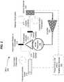
- FIG. 2shows the first example 200 of an OEO based on the cross modulation between two polarization modes in the WGM resonator.
- This OEO 200includes a tunable laser 210 that produces a CW laser beam for the OEO 200, an WGM resonator modulator based on the design in FIGS. 1A and 1B with an electro-optic WGM resonator 110, an evanescent coupler 214 for coupling light into the WGM resonator 110 for optical modulation, delay and filtering and coupling modulated light out of the WGM resonator 110, and an optical detector 220 for interfacing the optical and electrical portions of the OEO feedback loop.
- An optional amplifier 230may be coupled in the electrical portion of the OEO loop to amplify the output signal from the detector 220.
- the laser 210is linearly polarized and is split into two laser beams along two optical paths by an optical splitter 212 located between the laser 210 and the evanescent coupler 214.
- the first optical pathincludes a polarization rotator or a polarization controller 215 which rotates the optical polarization of the first laser beam that is not modulated by 90 degrees.
- the second optical pathleads to the evanescent coupler 214 and the WGM resonator modulator, and an optical polarizer 216 that transmits light in a polarization orthogonal to the input laser polarization and rejects light in the input laser polarization.
- An optical combiner 217is provided to combine light in the first and second optical paths to produce a combined output beam to the optical detector 220. The beat between the two beams at the combiner 217 is detected by the detector 220 and is converted to a single sideband (SSB) signal.
- SSBsingle sideband
- the opto-electronic loop of the OEO 200 in FIG. 2has an optical portion formed by the WGM resonator 110 as an optical delay element, an optical filter and an optical modulator, and an electrical portion which includes the optical detector 220 (e.g., a photodiode), and the electrical feedback path to the electrodes on the resonator 110 (including the amplifier 230).
- Thisis a closed loop and can be operated to have a loop gain higher than the loop loss and the feedback to the resonator 110 can be in phase. Under such conditions, the closed loop is a positive feedback loop and will oscillate as an opto-electronic oscillator (OEO) at a frequency at which the light in the resonator 110 is modulated.
- OEOopto-electronic oscillator
- the tunable laser 210is locked in frequency to the mode of the modulator 110 in one of the two orthogonal polarizations, e.g., the extraordinary polarization.
- This laser lockingcan be achieved by various techniques.
- a Pound-Drever-Hall (PDH) stabilization module 240is used to lock the laser 210.
- PDHPound-Drever-Hall
- Various PDH stabilization implementationsare known.
- an injection locking based on an optical feedback from the resonator 110is used without the PDH stabilization module 240.
- the laser 210(e.g., a diode laser) can be optically coupled to the WGM resonator 110 via the evanescent coupler 214 that couples light out of the resonator 110 back to the laser 210.
- This feedback light of the resonator 110is injected back to the laser 210 to stabilize the laser 210 so that the laser wavelength is locked at the wavelength of the WGM mode in the resonator 110 and to reduce the linewidth of the laser 210.
- One way to achieve this injection lockingis described in U.S. Patent Application No. 12/139,449 entitled "TUNABLE LASERS LOCKED TO WHISPERING GALLERY MODE RESONATORS".
- the WGM resonator 110supports two WGM polarization modes: the ordinary wave and the extra-ordinary wave.
- the evanescent coupler 214e.g., a prism coupler
- the optical polarizer 216can be oriented to select one of the modulated light in the two modes for the optical detection and conversion at the optical detector 220.
- the optical polarizer 216can be used to suppress the ordinary emission in the output allowing only the signal of the extra-ordinary wave to be directed to the optical detector.
- Output of extraordinary polarizationis mixed coherently by aligning polarization in the other optical path with small portion of initial laser's power to produce AM microwave signal at detector 220.
- the detector outputis fed back to the modulator 110.
- oscillations of a fixed frequency at FSR of extraordinary polarizationare suppressed because of polarized output and the OEO oscillator operates at the tunable differential ordinary-extraordinary frequency.
- polarization selective elements for output couplingmay be implemented for the OEO 200 in FIG. 2 .
- a prism-based output coupler with a polarizercan be used as shown in FIG. 2 .
- a probe prism of a high refractive indexe.g., a Ge prism
- this prismcouples out extraordinary polarization more efficiently than ordinary one.
- an optical detectorcan be attached to the rim of the resonator 110 through a transparent spacer.
- the ordinary polarizationhas an index (n2) higher than that of the evanescent field which allows simple and compact suppression of the fixed frequency oscillation.
- WGM resonatorsare axio-symmetric dielectric structures that support modes with very high quality factors (e.g., 2 ⁇ 10 9 ).
- Such WGM resonatorscan be configured so that sidebands on the optical carrier at the RF frequency are generated at the output when an optical mode is excited with the pump laser light and a RF signal with a frequency corresponding to the free spectral range (FSR) of the resonator are simultaneously applied.
- FSRfree spectral range
- Such a modulatorcan improve the OEO properties.
- An efficient OEOcalls for the intrinsically amplitude modulation.
- the WGM-based electro-optic modulation (EOM) schemeby constructing a structure that produces single sideband modulation (SSB).
- SSBsingle sideband modulation
- Such a modulationalways has an amplitude counterpart. This can be accomplished by applying the RF field along the radius of a WGM resonator produced from a Zcut lithium niobate preform.
- Such an RF fieldcouples optical TE and TM mode families of the WGM resonator due to the non-diagonal element r 51 of the electro-optic tensor of the material. Because the TE and TM mode families are frequency shifted with respect to each other, only one modulation sideband is generated.
- the modes belonging to different mode familiesmove in frequency, but at different rates.
- the mode spacing, and the corresponding modulation frequency given by the mode spacingcan be tuned.
- This configurationleads to a highly efficient, tunable, narrowband modulator, the three parameters that allow realization of a high performance, tunable OEO.
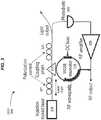
- FIG. 3shows another OEO example 300 based on the above cross modulation of two polarization modes in the WGM resonator 110.
- the semiconductor laser 310is injection locked to the lithium niobate or tantalate resonator 110 arranged as a SSB modulator.
- the output of the modulator 110may be sent to a semiconductor optical amplifier (SOA) before entering a long length of fiber that redirects light to the optical detector 220.
- SOAsemiconductor optical amplifier
- the optical detector 220produces an electric signal that is amplified before being fed back to the modulator 110 to complete the OEO loop.
- the narrow bandwidth of the resonator 110provides the filter function for the loop, and the change in the mode spacing produced by the applied DC voltage bias tunes the frequency.
- Such an oscillatormay be tuned from 20 to 35 GHz.
- the spectral purity goalcorresponds to the phase noise of -120 dBc at 100 kHz.
- the OEO 300 in FIG. 3implements two polarization controllers 321 and 322 to achieve the cross modulation of the two polarization modes in the resonator 110.
- the first polarization controller 321is placed in the optical path (e.g., the fiber) between the laser 310 and the evanescent coupler 214 to place the polarization of the laser light at 45 degrees with respect to either one of the two orthogonal polarizations in the resonator 110.
- one half of the input laser lightis coupled into the WGM resonator and the remaining one half is reflected, without entering into the resonator 110, to pass through the evanescent prism coupler 214 into the output optical path to the optical detector 220.
- the one half of the laser light coupled into the resonator 110is modulated and filtered and is then coupled out by the coupler 214 to overlap with the reflected laser input light.
- the combined lightis then directed into the detector 220.
- the WGM resonator 110can be made of an electro-optic material with proper non-diagonal electro-optic coefficients (e.g. lithium niobate or lithium tantalate).
- the optical WGMsoverlap with the field of an RF resonator or waveguide which can be built on the surface of the WGM resonator.
- electric field Elis presented as a sum of two counterpropagating waves, and V is the volume of the WGM resonator.
- the possibility of interaction between two WGM mode families having different polarizationsis important for our application because the mode families can be tuned one with respect to the other using the same bias voltage applied to the resonator. Moreover, because the mode families are shifted one with respect to the other it is possible to realize single sideband modulation in the system.
- the interaction between the light and RF signalis not always possible. For instance, if the RF field is homogeneous and is applied along, say, Z-axis of lithium niobate WGM resonator, the coupling between the optical modes having TM with its electric field parallel to Z and TE with its electric field perpendicular to Z is forbidden. However, it is possible to realize resonators where neither pure TE not TM mode families exist. The interaction is allowed among those modes if the spatial overlap integral between the modes is not equal to zero.
- Those coefficientsintroduce coupling between TE and TM WGMs in a resonator fabricated from a z-cut LiNbO3 preform if the RF field has a radial component.
- the averaged interaction energyis generally zero because ne ⁇ no.
- periodical poling of the material or creating a special electrode shape for the RF mode phasematches the interaction such that ⁇ ⁇ 0.
- a resonatorcan be fabricated from, say, x-cut and z-cut segments that results in the interaction between RF and different mode families.
- FIG. 4shows measurements of the interaction of TE and TM mode families in a single sideband modulation in a WGM resonator modulator having a 35-GHz free spectral range. Such a modulator generates only one sideband.
- the feature of this systemis that the resonator modulation is achieved between the modes separated not by the free spectral range of the resonator, but rather by some value given by the resonator shape, the operating temperature, and the bias voltage applied to the resonator.
Landscapes
- Physics & Mathematics (AREA)
- Electromagnetism (AREA)
- Optics & Photonics (AREA)
- Engineering & Computer Science (AREA)
- Plasma & Fusion (AREA)
- Condensed Matter Physics & Semiconductors (AREA)
- General Physics & Mathematics (AREA)
- Automation & Control Theory (AREA)
- Optical Modulation, Optical Deflection, Nonlinear Optics, Optical Demodulation, Optical Logic Elements (AREA)
- Semiconductor Lasers (AREA)
Description
- This document relates to optical resonators and optical devices based on optical resonators.
- Optical resonators may be used to spatially confine resonant optical energy in a limited cavity with a low optical loss. The resonance of an optical resonator may be used to provide various useful functions such as optical filtering, optical modulation, optical amplification, optical delay, and others. Light can be coupled into or out of optical resonators via various coupling mechanisms according to the configurations of the resonators. For example, Fabry-Perot optical resonators with two reflectors at two terminals may use partial optical transmission of at least one reflector to receive or export light.
- Optical whispering gallery mode (WGM) resonators confine light in a whispering gallery mode that is totally reflected within a closed circular optical path. Unlike Fabry-Perot resonators, light in WGM resonators cannot exit the resonators by optical transmission. Light in a WGM resonator "leaks" out of the exterior surface of the closed circular optical path of a WGM resonator via the evanescence field of the WG mode. An optical coupler can be used to couple light into or out of the WGM resonator via this evanescent field.
- Reference is directed to
US 2005/147355A which describes whispering gallery modes resonators that are optically coupled to one or two waveguide grating couplers formed on a substrate. - The specification of this application describes, among others, examples and implementations of photonic devices and techniques based on whispering gallery mode resonators formed of electro-optic materials to effectuate cross modulation between whispering gallery modes of different polarizations in the resonators.
- The invention is defined by the independent claims to which reference should be made.
- These and other aspects, associated examples and implementations are described in detail in the drawings, the detailed description, and the claims.
FIGS. 1A and 1B show an example of an electro-optic WGM resonator modulator for an OEO.FIG. 2 shows an example of a cross-mode tunable WGM resonator modulator OEO using the electro-optic WGM resonator modulator inFIGS. 1A and 1B .FIG. 3 shows another example of a cross-mode tunable WGM resonator modulator OEO using the electro-optic WGM resonator modulator inFIGS. 1A and 1B .FIG. 4 shows measurements of the interaction of TE and TM mode families in a single sideband modulation in a WGM resonator modulator having a 35-GHz free spectral range.- An opto-electronic oscillator (OEO) is an oscillator with a positive feedback loop that has both electronic and optical components. See, e.g.,
U.S. Patent Nos. 5,723,856 to Yao and Maleki and5,777,778 to Yao . Such an OEO includes an electrically controllable optical modulator and at least one active opto-electronic feedback loop that comprises an optical part and an electrical part interconnected by a photodetector. The opto-electronic feedback loop receives the modulated optical output from the modulator and converts it into an electrical signal to control the modulator. The loop produces a desired delay and feeds the electrical signal in phase to the modulator to generate and sustain both optical modulation and electrical oscillation at the modulation frequency of the modulator when the total loop gain of the active opto-electronic loop and any other additional feedback loops exceeds the total loss. - Therefore, OEOs use optical modulation to produce oscillations in frequency spectral ranges that are outside the optical spectrum, such as in RF and microwave frequencies. The generated oscillating signals are tunable in frequencies and can have narrow spectral linewidths and low phase noise in comparison with the signals produced by other RF and microwaves oscillators. Notably, the OEOs are optical and electronic hybrid devices and thus can be used in various applications.
- The OEOs described in this document use a whispering mode gallery mode resonator made of an electro-optic material as the optical modulator for modulating the CW laser light from a laser, to filter the modulated laser light and to provide the optical delay due to the high Q factor for the feedback loop. The electro-optic material supports two mutually orthogonal polarizations which may be referred to as the original wave and the extra-ordinary wave, or the TM mode and the TE mode. These two different polarized waves undergo a frequency shift with respect to each other in the electro-optic WGM resonator modulator and proper control of the polarization in OEO feedback loop can be used to produce one modulation sideband in the detector output of the optical detector that interconnects the electrical portion and the optical portion of the feedback loop. Therefore, a single sideband (SSB) modulation can be achieved in the OEO and provides a flexible operating frequency range that is not available in OEOs that operate at their free spectral range (FSR) .
FIGS. 1A and 1B show an example of an electro-opticWGM resonator modulator 100 having aWGM resonator 110. The electro-optic material for the entire or part of theresonator 110 may be an electro-optic crystal such as Lithium Niobate ("Lithium Niobate resonator") or a semiconductor multiple quantum well structure. One ormore electrodes resonator 110 to apply a control electrical field in at least the region where the WG modes are present to control the index of the electro-optical material and to change the filter function of the resonator. Assuming theresonator 110 has disk or ring geometry, theelectrode 111 may be formed on the top of theresonator 110 and theelectrode 112 may be formed on the bottom of theresonator 110 as illustrated in the side view of the device inFIG. 1B . In one implementation, theelectrodes electrodes electrodes tuning control unit 130 such as a control circuit may be used to supply theelectrical control signal 131 to theelectrodes - In operating the
resonator modulator 100, thecontrol unit 130 may supply a voltage as the electrical control signal to theelectrodes DC voltage 132 to set the resonance peak of theresonator 100 at a desired spectral location. The DC voltage may be adjusted by thecontrol unit 130 to tune the spectral position of the transmission peak when such tuning is needed. - For example, a Z-cutLiNbO3 disk cavity with a diameter ofd = 4.8mm and a thickness of 170µm may be used as the
resonator 110. The cavity perimeter edge may be prepared in the toroidal shape with a 100µm radius of curvature. As an alternative to the strip electrodes shown inFIG. 1A , the top and bottom surfaces of the disk resonator may be coated with conductive layers for receiving the external electrical control signal. A metal such as indium may be used to form the conductive coatings. The signal modulation is achieved by applying and adjusting a modulation control voltage to the top and bottom conductive coatings. Each conductive coating may be absent on the central part of the resonator and be present at the perimeter edge of the resonator where WGMs are localized. - WGM narrowband modulators operate at a particular frequency determined by the FSR of the WGM resonator. The following OEO examples provide a SSB modulation with a compressed carrier (i.e. frequency shifter) to provide a tunable OEO operation.
FIGS. 2 and3 show such OEO examples. - The cross-modulation between modes of different polarizations in the WGM resonator is used to achieve the SSB modulation. In optically transparent ferroelectrics like lithium niobate and lithium tantalate electro-optical indexes of ordinary and extraordinary polarization differ significantly. This allows simple and very efficient differential detuning of one mode from another with just regular DC bias. Mixed with additional microwave field of frequency equal to difference of resonant optical frequencies the modes would interact if properly phase matched in collinear configuration. Phase matching does not happen automatically since refractive indexes of ordinary, extraordinary optical modes (i.e., mode 1 and mode 2) and the microwave mode are different. We propose to exploit specifically undulated electrode which modulates electric field along the rim of the WGM resonator. The frequency of the required spatial modulation is determined from phase matching conditions:


- An optical grating written on electrode of the modulator designed for phase matching in tantalate resonators of 400-µm diameter has a period of 138 degrees. For niobate this value is about 6 degrees. Both gratings can be easily doable with lithography. The former may be manufacturable even by hands since spatial period is 0.48mm only. The last means that sub-millimeter tantalate modulator with regular horseshoe or ring electrode does have ability of cross-polarized ordinary to extraordinary (o-e) modulation.
- This kind of modulation accepts one polarization of light, and rotates its polarization while microwave modulation.
- The electro-optical WGM resonator modulator operates at differential frequencies between optical modes in mutually orthogonal polarizations. In some nonlinear crystals, this difference in frequency can be tuned with the control voltage and the operating temperature. For instance, lithium niobate shows three times different electro-optical index of both polarizations. It was previously demonstrated that fast frequency shift of the resonator made of lithium niobate is as high as 20GHz per 100V for one and 7GHz for another. Thus tunability span of OEO based on lithium niobate cross-mode modulator is 13GHz. Hence, the operational frequency of 35GHz high-efficient receiver can be changed very quickly by voltage through ∼30%. On the other hand thermal operational point can change this differential frequency even further to terahertz range. The SSB modulation used in the present designs eliminates the mode for the second sideband. Lithium tantalate-based modulators tend to have better efficiency of modulation than lithium niobate based modulators since mode overlapping in the Lithium tantalate is much better as a result of very similar refractive indexes of both polarizations.
- Therefore, the present modulator designs combine advantages of narrowband high-Q -factor WGMR-based modulator with tunability and can be tuned within the differential detuning range, from X band to W band. The WGMR modulator of high efficiency can be a tunable cross-mode modulator to tune OEO frequency.
FIG. 2 shows the first example 200 of an OEO based on the cross modulation between two polarization modes in the WGM resonator. ThisOEO 200 includes atunable laser 210 that produces a CW laser beam for theOEO 200, an WGM resonator modulator based on the design inFIGS. 1A and 1B with an electro-optic WGM resonator 110, anevanescent coupler 214 for coupling light into theWGM resonator 110 for optical modulation, delay and filtering and coupling modulated light out of theWGM resonator 110, and anoptical detector 220 for interfacing the optical and electrical portions of the OEO feedback loop. Anoptional amplifier 230 may be coupled in the electrical portion of the OEO loop to amplify the output signal from thedetector 220.- The
laser 210 is linearly polarized and is split into two laser beams along two optical paths by anoptical splitter 212 located between thelaser 210 and theevanescent coupler 214. The first optical path includes a polarization rotator or apolarization controller 215 which rotates the optical polarization of the first laser beam that is not modulated by 90 degrees. The second optical path leads to theevanescent coupler 214 and the WGM resonator modulator, and anoptical polarizer 216 that transmits light in a polarization orthogonal to the input laser polarization and rejects light in the input laser polarization. Anoptical combiner 217 is provided to combine light in the first and second optical paths to produce a combined output beam to theoptical detector 220. The beat between the two beams at thecombiner 217 is detected by thedetector 220 and is converted to a single sideband (SSB) signal. - The opto-electronic loop of the
OEO 200 inFIG. 2 has an optical portion formed by theWGM resonator 110 as an optical delay element, an optical filter and an optical modulator, and an electrical portion which includes the optical detector 220 (e.g., a photodiode), and the electrical feedback path to the electrodes on the resonator 110 (including the amplifier 230). This is a closed loop and can be operated to have a loop gain higher than the loop loss and the feedback to theresonator 110 can be in phase. Under such conditions, the closed loop is a positive feedback loop and will oscillate as an opto-electronic oscillator (OEO) at a frequency at which the light in theresonator 110 is modulated. - The
tunable laser 210 is locked in frequency to the mode of themodulator 110 in one of the two orthogonal polarizations, e.g., the extraordinary polarization. This laser locking can be achieved by various techniques. In one example, which is shown inFIG. 2 , a Pound-Drever-Hall (PDH)stabilization module 240 is used to lock thelaser 210. Various PDH stabilization implementations are known. In another example, an injection locking based on an optical feedback from theresonator 110 is used without thePDH stabilization module 240. The laser 210 (e.g., a diode laser) can be optically coupled to theWGM resonator 110 via theevanescent coupler 214 that couples light out of theresonator 110 back to thelaser 210. This feedback light of theresonator 110 is injected back to thelaser 210 to stabilize thelaser 210 so that the laser wavelength is locked at the wavelength of the WGM mode in theresonator 110 and to reduce the linewidth of thelaser 210. One way to achieve this injection locking is described inU.S. Patent Application No. 12/139,449 entitled "TUNABLE LASERS LOCKED TO WHISPERING GALLERY MODE RESONATORS". - The
WGM resonator 110 supports two WGM polarization modes: the ordinary wave and the extra-ordinary wave. The evanescent coupler 214 (e.g., a prism coupler) can optically couple light in both modes. Theoptical polarizer 216 can be oriented to select one of the modulated light in the two modes for the optical detection and conversion at theoptical detector 220. As an example, theoptical polarizer 216 can be used to suppress the ordinary emission in the output allowing only the signal of the extra-ordinary wave to be directed to the optical detector. Output of extraordinary polarization is mixed coherently by aligning polarization in the other optical path with small portion of initial laser's power to produce AM microwave signal atdetector 220. The detector output is fed back to themodulator 110. In this scheme oscillations of a fixed frequency at FSR of extraordinary polarization are suppressed because of polarized output and the OEO oscillator operates at the tunable differential ordinary-extraordinary frequency. - Various polarization selective elements for output coupling may be implemented for the
OEO 200 inFIG. 2 . For example, a prism-based output coupler with a polarizer can be used as shown inFIG. 2 . In another example, a probe prism of a high refractive index (e.g., a Ge prism) can be used and, due to boundary conditions, this prism couples out extraordinary polarization more efficiently than ordinary one. As a result in OEO pumped with ordinary polarization oscillations at fixed FSR can be suppressed. In yet another example, an optical detector can be attached to the rim of theresonator 110 through a transparent spacer. The ordinary polarization has an index (n2) higher than that of the evanescent field which allows simple and compact suppression of the fixed frequency oscillation. - Hence, based on the above example, it is possible to achieve multiple functions in a tunable OEO: optical modulation of light, optical filtering, optical delay and optical tuning of the frequency, with a single WGM resonator made with an electro-optic crystal. WGM resonators are axio-symmetric dielectric structures that support modes with very high quality factors (e.g., 2×10⁹). Such WGM resonators can be configured so that sidebands on the optical carrier at the RF frequency are generated at the output when an optical mode is excited with the pump laser light and a RF signal with a frequency corresponding to the free spectral range (FSR) of the resonator are simultaneously applied. This scheme is used to realize an efficient EOM. Such a modulator can improve the OEO properties. An efficient OEO calls for the intrinsically amplitude modulation. The WGM-based electro-optic modulation (EOM) scheme by constructing a structure that produces single sideband modulation (SSB). Such a modulation always has an amplitude counterpart. This can be accomplished by applying the RF field along the radius of a WGM resonator produced from a Zcut lithium niobate preform. Such an RF field couples optical TE and TM mode families of the WGM resonator due to the non-diagonal element r51 of the electro-optic tensor of the material. Because the TE and TM mode families are frequency shifted with respect to each other, only one modulation sideband is generated. By applying a DC voltage to the WGM resonator the modes belonging to different mode families move in frequency, but at different rates. Thus, the mode spacing, and the corresponding modulation frequency given by the mode spacing, can be tuned. This configuration leads to a highly efficient, tunable, narrowband modulator, the three parameters that allow realization of a high performance, tunable OEO.
FIG. 3 shows another OEO example 300 based on the above cross modulation of two polarization modes in theWGM resonator 110. Thesemiconductor laser 310 is injection locked to the lithium niobate ortantalate resonator 110 arranged as a SSB modulator. The output of themodulator 110 may be sent to a semiconductor optical amplifier (SOA) before entering a long length of fiber that redirects light to theoptical detector 220. Theoptical detector 220 produces an electric signal that is amplified before being fed back to themodulator 110 to complete the OEO loop. The narrow bandwidth of theresonator 110 provides the filter function for the loop, and the change in the mode spacing produced by the applied DC voltage bias tunes the frequency. Such an oscillator may be tuned from 20 to 35 GHz. The spectral purity goal corresponds to the phase noise of -120 dBc at 100 kHz.- Different from the two optical path design in the
OEO 200 shown inFIG. 2 , the OEO 300 inFIG. 3 implements twopolarization controllers resonator 110. Thefirst polarization controller 321 is placed in the optical path (e.g., the fiber) between thelaser 310 and theevanescent coupler 214 to place the polarization of the laser light at 45 degrees with respect to either one of the two orthogonal polarizations in theresonator 110. Under this input polarization configuration, one half of the input laser light is coupled into the WGM resonator and the remaining one half is reflected, without entering into theresonator 110, to pass through theevanescent prism coupler 214 into the output optical path to theoptical detector 220. The one half of the laser light coupled into theresonator 110 is modulated and filtered and is then coupled out by thecoupler 214 to overlap with the reflected laser input light. The combined light is then directed into thedetector 220. - The
WGM resonator 110 can be made of an electro-optic material with proper non-diagonal electro-optic coefficients (e.g. lithium niobate or lithium tantalate). The optical WGMs overlap with the field of an RF resonator or waveguide which can be built on the surface of the WGM resonator. Two optical WGMs characterized with electric field operators E1 and E2 are coupled with the RF field EM in the case of nonzero integral proportional to the interaction energy
- The possibility of interaction between two WGM mode families having different polarizations is important for our application because the mode families can be tuned one with respect to the other using the same bias voltage applied to the resonator. Moreover, because the mode families are shifted one with respect to the other it is possible to realize single sideband modulation in the system. On the other hand, the interaction between the light and RF signal is not always possible. For instance, if the RF field is homogeneous and is applied along, say, Z-axis of lithium niobate WGM resonator, the coupling between the optical modes having TM with its electric field parallel to Z and TE with its electric field perpendicular to Z is forbidden. However, it is possible to realize resonators where neither pure TE not TM mode families exist. The interaction is allowed among those modes if the spatial overlap integral between the modes is not equal to zero.
- Another possibility is related to the usage of non-diagonal elements of the linear electro-optic tensor of the material. For example, lithium niobate has nonzero electro-optic coefficients r42 = r51. Those coefficients introduce coupling between TE and TM WGMs in a resonator fabricated from a z-cut LiNbO3 preform if the RF field has a radial component. The space averaged interaction energy for the optical and RF fields is given by

E TE =z ETE. The averaged interaction energy is generally zero because ne ≠ no. However, either periodical poling of the material or creating a special electrode shape for the RF mode phase matches the interaction such thatε ≠ 0. In addition, a resonator can be fabricated from, say, x-cut and z-cut segments that results in the interaction between RF and different mode families. FIG. 4 shows measurements of the interaction of TE and TM mode families in a single sideband modulation in a WGM resonator modulator having a 35-GHz free spectral range. Such a modulator generates only one sideband. The feature of this system is that the resonator modulation is achieved between the modes separated not by the free spectral range of the resonator, but rather by some value given by the resonator shape, the operating temperature, and the bias voltage applied to the resonator.


Claims (12)
- A photonic device, comprising:a laser (210) that is tunable and produces a laser beam at a laser frequency and at a first polarization;an optical resonator (110) exhibiting an electro-optic effect and structured to support a first whispering gallery mode in a first polarization and a second whispering gallery mode in a second polarization circulating in the optical resonator, wherein the first polarization and second polarization are mutually orthogonal;an evanescent optical coupler (214) configured for evanescently coupling a portion of the laser beam into the optical resonator and evanescently coupling out of the resonator a resonator output light comprising a first light having the first polarization and a second light having the second polarization;electrodes (111, 112) formed on the optical resonator and configured to apply a modulation control signal to effectuate an optical modulation of light based on the electro-optic effect;a polarization control device (215) configured to rotate a polarization of a portion of the laser beam that does not enter the optical resonator to produce a modified laser light at the second polarization;an optical polarizer (216) interposed between the optical evanescent optical coupler and an optical combiner (217), wherein the optical polarizer (216) is configured to block the first resonator output light and allow the second resonator output light to pass through the optical polarizer (216), and wherein the optical combiner (217) is configured to receive the modified laser light and the second resonator output light that passes through the optical polarizer (216);an optical detector (220) configured to receive an output light of the optical combiner so as to allow the modified laser light and the second resonator output light to interfere at the optical detector to produce a single modulation sideband;a laser locking mechanism (240) coupled between the optical detector and the laser and configured to lock the laser frequency to one of the first and second whispering gallery mode resonances of the optical resonator; anda feedback circuit coupled between the optical detector and the electrodes to receive a detector output from the optical detector and to produce the modulation control signal at a tunable modulation frequency.
- The device as in claim 1, wherein:
the laser locking mechanism comprises a Pound Drever- Hall (PDH) stabilization module that locks the laser. - The device as in claim 1, 2 further comprising;
an optical splitter (212) located in an optical path between the laser (210) and the evanescent optical coupler (214) to split the laser beam from the laser into a first portion along a first optical path directing the first portion away from the evanescent coupler and a second portion along a second optical path leading to the evanescent optical coupler;
and wherein said polarization control device (215) in the first optical path rotates polarization of the first portion by 90 degrees;
said optical polarizer (216) is located on an optical path of the resonator output light after the evanescent optical coupler to transmit light in a polarization that is parallel to the polarization of light output by the first optical polarization device. - The device as in claim 1, wherein:
the optical resonator is made of lithium niobate. - The device as in claim 1, wherein:
the optical resonator is made of lithium tantalite. - The device as in claim 1, wherein:
the electrodes formed on the optical resonator comprise electrodes that receive the modulation control signal for optical modulation and a DC bias electrode to apply a DC bias voltage to tune the optical resonator. - The device as in claim 1, wherein:
the laser is a semiconductor laser. - The device as in claim 1, wherein the feedback circuit includes an amplifier (230) that amplifies the detector output from the detector circuit to produce the modulation control signal at the tunable modulation frequency.
- A photonic device, comprising:a laser (310) that is tunable and produces a laser beam at a laser frequency and at a first polarization;an optical resonator (110) exhibiting an electro-optic effect and structured to support a first whispering gallery mode in a first polarization and a second whispering gallery mode in a second polarization circulating in the optical resonator, wherein the first polarization and second polarization are mutually orthogonal, an evanescent coupler (214) optically coupled to the optical resonator and to the laser such that the optical resonator receives a portion of the laser beam and produces a modulated laser beam comprising a first light having the first polarization and a second light having the second polarization;electrodes (111, 112) formed on the optical resonator and configured to apply a modulation control signal having a modulation frequency to effectuate an optical modulation of light based on the electro-optic effect;an active opto-electronic feedback loop (220, 230) that comprises an optical part coupled to the optical resonator to receive the modulated laser beam and an electrical part configured to produce the modulation control signal, and an optical detector (230) coupled between the optical part and the electrical part, the opto-electronic feedback loop being configured to feed the modulation control signal in phase to the electrodes on the optical resonator to generate and sustain both optical modulation and electrical oscillation at the modulation frequency; anda polarization control mechanism (321, 322) configured to control polarization of light from the tunable laser such that said portion of the laser beam enters into the optical resonator and another portion of the laser beam does not enter the optical resonator and is received at the optical detector to interfere with light of the second polarization coupled out of the optical resonator to produce a single modulation sideband at a modulation frequency which is a difference between frequencies of the first and second whispering gallery modes at the two mutually orthogonal polarizations inside the optical resonator.
- The device as in claim 9, wherein:
the optical resonator is made of lithium niobate. - The device as in claim 9, wherein:
the optical resonator is made of lithium tantalite. - The device as in claim 9, wherein:
the electrodes formed on the optical resonator comprise electrodes that receive the modulation control signal for optical modulation and a DC bias electrode to apply a DC bias voltage to tune the optical resonator.
Applications Claiming Priority (2)
| Application Number | Priority Date | Filing Date | Title |
|---|---|---|---|
| US291907P | 2007-11-13 | 2007-11-13 | |
| PCT/US2008/083469WO2009064934A2 (en) | 2007-11-13 | 2008-11-13 | Cross modulation-based opto-electronic oscillator with tunable electro-optic optical whispering gallery mode resonator |
Publications (3)
| Publication Number | Publication Date |
|---|---|
| EP2210318A2 EP2210318A2 (en) | 2010-07-28 |
| EP2210318A4 EP2210318A4 (en) | 2015-01-07 |
| EP2210318B1true EP2210318B1 (en) | 2020-01-01 |
Family
ID=40639446
Family Applications (1)
| Application Number | Title | Priority Date | Filing Date |
|---|---|---|---|
| EP08848683.2AActiveEP2210318B1 (en) | 2007-11-13 | 2008-11-13 | Cross modulation-based opto-electronic oscillator with tunable electro-optic optical whispering gallery mode resonator |
Country Status (4)
| Country | Link |
|---|---|
| US (1) | US7801189B2 (en) |
| EP (1) | EP2210318B1 (en) |
| CN (1) | CN101911403B (en) |
| WO (1) | WO2009064934A2 (en) |
Families Citing this family (61)
| Publication number | Priority date | Publication date | Assignee | Title |
|---|---|---|---|---|
| US8124927B2 (en)* | 2007-05-29 | 2012-02-28 | California Institute Of Technology | Detecting light in whispering-gallery-mode resonators |
| EP2162784B1 (en)* | 2007-06-13 | 2017-08-09 | Strobe, Inc. | Tunable lasers locked to whispering gallery mode resonators |
| US7929589B1 (en) | 2007-06-13 | 2011-04-19 | Oewaves, Inc. | Diffractive grating coupled whispering gallery mode resonators |
| US8164816B1 (en)* | 2007-08-31 | 2012-04-24 | California Institute Of Technology | Stabilizing optical resonators |
| US7665891B1 (en)* | 2007-09-20 | 2010-02-23 | The United States Of America As Represented By The Administrator Of The National Aeronautics And Space Administration | Differential temperature sensor system and method |
| US8210044B1 (en) | 2007-10-12 | 2012-07-03 | California Institute Of Technology | Covert laser remote sensing and vibrometry |
| CN101904115B (en)* | 2007-11-13 | 2014-10-22 | 光电波股份有限公司 | Cross-correlation homodyne detection with low phase noise based on photonic technology |
| US8155914B2 (en) | 2007-11-13 | 2012-04-10 | Oewaves, Inc. | Measuring phase noise in radio frequency, microwave or millimeter signals based on photonic delay |
| US8111722B1 (en) | 2008-03-03 | 2012-02-07 | Oewaves, Inc. | Low-noise RF oscillation and optical comb generation based on nonlinear optical resonator |
| US7869472B2 (en)* | 2008-03-11 | 2011-01-11 | Oewaves, Inc. | Optical locking based on optical resonators with high quality factors |
| US8089684B1 (en) | 2008-03-14 | 2012-01-03 | Oewaves, Inc. | Photonic RF and microwave phase shifters |
| WO2009137202A2 (en)* | 2008-04-03 | 2009-11-12 | California Institute Of Technology | Optical sensing based on overlapping optical modes in optical resonator sensors and interferometric sensors |
| US8094359B1 (en) | 2008-05-15 | 2012-01-10 | Oewaves, Inc. | Electro-optic whispering-gallery-mode resonator devices |
| US8102597B1 (en) | 2008-05-15 | 2012-01-24 | Oewaves, Inc. | Structures and fabrication of whispering-gallery-mode resonators |
| US8452139B1 (en) | 2008-07-25 | 2013-05-28 | Oewaves, Inc. | Wide-band RF photonic receivers and other devices using two optical modes of different quality factors |
| US8331008B1 (en)* | 2008-10-14 | 2012-12-11 | Oewaves, Inc. | Photonic microwave and RF receivers based on electro-optic whispering-gallery-mode resonators |
| US8159736B2 (en)* | 2008-11-13 | 2012-04-17 | Oewaves, Inc. | Tunable single sideband modulators based on electro-optic optical whispering gallery mode resonators and their applications |
| US8761603B1 (en) | 2009-02-25 | 2014-06-24 | Oewaves, Inc. | Dynamically reconfigurable sensor arrays |
| US8498539B1 (en) | 2009-04-21 | 2013-07-30 | Oewaves, Inc. | Dielectric photonic receivers and concentrators for radio frequency and microwave applications |
| JP2010258198A (en)* | 2009-04-24 | 2010-11-11 | Fujifilm Corp | Mode-locked solid-state laser device |
| WO2010127151A2 (en)* | 2009-04-29 | 2010-11-04 | Montana State University | Precise broadband frequency modulated laser |
| US8417076B2 (en)* | 2009-06-22 | 2013-04-09 | Oewaves, Inc. | Tunable photonic microwave or radio frequency receivers based on electro-optic optical whispering gallery mode resonators |
| US8331409B1 (en) | 2010-01-18 | 2012-12-11 | Oewaves, Inc. | Locking of a laser to an optical interferometer that is stabilized to a reference frequency |
| US8514400B2 (en) | 2010-03-23 | 2013-08-20 | Oewaves, Inc. | Optical gyroscope sensors based on optical whispering gallery mode resonators |
| US8564869B1 (en) | 2010-07-15 | 2013-10-22 | Oewaves, Inc. | Voltage controlled tunable single sideband modulators and devices based on electro-optic optical whispering gallery mode resonators |
| US8605760B2 (en) | 2010-08-10 | 2013-12-10 | Oewaves, Inc. | Feedback-enhanced self-injection locking of lasers to optical resonators |
| CN102163795B (en)* | 2011-03-15 | 2012-06-27 | 中国科学院半导体研究所 | Optoelectronic oscillator with tunable broadband frequency |
| CN102163801B (en)* | 2011-03-24 | 2012-10-17 | 贵州大学 | Photoelectric Oscillator Using Active Semiconductor Resonator |
| EP2710694B1 (en) | 2011-05-16 | 2018-07-04 | Oewaves, Inc. | Generation of single optical tone, rf oscillation signal and optical comb in a triple-oscillator device based on nonlinear optical resonator |
| US8736845B2 (en) | 2011-05-24 | 2014-05-27 | Honeywell International Inc. | Frequency stabilized laser system |
| WO2012177805A2 (en)* | 2011-06-20 | 2012-12-27 | Oewaves, Inc. | Stabilizing rf oscillator based on optical resonator |
| EP2702443B1 (en) | 2011-06-23 | 2018-11-07 | Oewaves, Inc. | Parametric regenerative oscillators based on opto-electronic feedback and optical regeneration via nonlinear optical mixing in whispering gallery mode optical resonators |
| CN104040808B (en)* | 2011-06-30 | 2016-11-16 | Oe电波公司 | Compact optical atomic clock and the application being mixed based on the parametrization nonlinear optics in Whispering-gallery-mode optical resonantor |
| GB2512522B (en) | 2011-12-23 | 2018-05-16 | Intel Corp | Integrated silicon optomechanical gyroscopes (OMGS) |
| US9097790B2 (en)* | 2012-02-02 | 2015-08-04 | The United States Of America As Represented By The Secretary Of The Army | Method and apparatus for providing radio frequency photonic filtering |
| EP2831966A4 (en) | 2012-03-27 | 2016-01-27 | Oewaves Inc | ADJUSTABLE OPTOELECTRONIC OSCILLATOR COMPRISING AN OPTICAL OPERATING RESONATOR FILTER WITH SELECTED MODULATION LATERAL BAND |
| US20150168748A1 (en)* | 2012-06-20 | 2015-06-18 | Cornell University | High frequency resonator modulator apparatus, method and applications |
| US8923352B2 (en) | 2012-08-10 | 2014-12-30 | Honeywell International Inc. | Laser with transmission and reflection mode feedback control |
| CN103235623A (en)* | 2013-03-25 | 2013-08-07 | 太原理工大学 | Optimal bias phase point detection control device for high-speed electrooptical modulator and method thereof |
| US10447409B2 (en)* | 2013-06-21 | 2019-10-15 | Northrop Grumman Systems Corporation | Optical channelizer for W-band detection |
| WO2015006494A1 (en)* | 2013-07-09 | 2015-01-15 | Board Of Trustees Of The Leland Stanford Junior University | Computation using a network of optical parametric oscillators |
| WO2015065479A1 (en)* | 2013-11-01 | 2015-05-07 | Halliburton Energy Services, Inc. | Downhole optical communication |
| US9197031B2 (en)* | 2014-02-14 | 2015-11-24 | Karoly Holczer | Laser stabilization with an actively controlled fabry-perot resonance cavity |
| JP2017514111A (en) | 2014-03-19 | 2017-06-01 | オーイーウェーブス, インク.Oewaves, Inc. | Optical atomic clock |
| CN103941518B (en)* | 2014-05-06 | 2016-07-06 | 中国科学院半导体研究所 | Adjustable full optical generator based on silicon-based micro ring resonator thermo-optical tunability mechanism |
| US9703045B2 (en)* | 2014-10-22 | 2017-07-11 | Massachusetts Institute Of Technology | Systems and methods for laser frequency stabilization using an arbitrarily birefringent resonator |
| US9703266B2 (en) | 2014-11-04 | 2017-07-11 | Spectracom Corporation | Independent fiber-optic reference apparatuses and methods thereof |
| CN104659637A (en)* | 2015-03-10 | 2015-05-27 | 中北大学 | Photoelectric oscillator based on optical resonant cavity |
| CN105896235B (en)* | 2016-06-08 | 2019-04-05 | 中国科学技术大学 | Optical-electronic oscillator based on multilayer film echo wall mode optical micro-cavity |
| CN106374324A (en)* | 2016-11-28 | 2017-02-01 | 中国科学院半导体研究所 | Tunable double-frequency optoelectronic oscillator system based on polarization modulator |
| DE102018216632B4 (en)* | 2018-09-27 | 2020-06-04 | Carl Zeiss Ag | Device for scanning the distance of an object |
| EP3857257A1 (en) | 2018-09-27 | 2021-08-04 | Carl Zeiss AG | Apparatus and method for determining the distance of an object by scanning |
| CN109990975B (en)* | 2019-04-10 | 2021-04-23 | 暨南大学 | Detection system, debugging system and sensor based on optical microcavity mechanical mode |
| US10955726B2 (en) | 2019-08-15 | 2021-03-23 | International Business Machines Corporation | Intracavity grating to suppress single order of ring resonator |
| US11362479B2 (en) | 2019-09-30 | 2022-06-14 | Gm Cruise Holdings Llc | Non-reciprocal optical assembly for injection locked laser |
| CN110729630B (en)* | 2019-10-11 | 2020-12-11 | 浙江大学 | A laser with high-speed wavelength tuning made of lithium niobate material |
| CN110729623B (en)* | 2019-10-18 | 2021-03-30 | 北京无线电计量测试研究所 | Microwave source |
| US11581946B2 (en)* | 2020-12-10 | 2023-02-14 | Oewaves, Inc. | Wideband photonic synthesizer stabilized to a reference clock using photonic components |
| CN117170123B (en)* | 2023-09-07 | 2024-03-29 | 哈尔滨工业大学 | A tunable signal filtering and encryption method based on electro-optical resonance effect |
| CN117039611B (en)* | 2023-10-09 | 2024-01-09 | 之江实验室 | Frequency multiplication terahertz photoelectric oscillator device and oscillation method thereof |
| CN119481928A (en)* | 2024-11-05 | 2025-02-18 | 哈尔滨工业大学 | A residual amplitude noise optimization system and method in a Pound-Drever-Hall system |
Family Cites Families (63)
| Publication number | Priority date | Publication date | Assignee | Title |
|---|---|---|---|---|
| US5220292A (en) | 1992-01-02 | 1993-06-15 | Raytheon Company | Microwave oscillator with noise degeneration feedback circuit |
| US5204640A (en) | 1992-02-10 | 1993-04-20 | California Institute Of Technology | Widely tunable oscillator stabilization using analog fiber optic delay line |
| US5723856A (en) | 1995-08-01 | 1998-03-03 | California Institute Of Technology | Opto-electronic oscillator having a positive feedback with an open loop gain greater than one |
| US5751747A (en) | 1995-12-20 | 1998-05-12 | California Institute Of Technology | Linear swept frequency generator |
| US5777778A (en) | 1996-01-23 | 1998-07-07 | California Institute Of Technology | Multi-Loop opto-electronic microwave oscillator with a wide tuning range |
| US6080586A (en) | 1996-04-05 | 2000-06-27 | California Institute Of Technology | Sub-micron chemical imaging with near-field laser desorption |
| US6178036B1 (en) | 1997-01-14 | 2001-01-23 | California Institute Of Technology | Opto-electronic devices and systems based on brillouin selective sideband amplification |
| US5929430A (en) | 1997-01-14 | 1999-07-27 | California Institute Of Technology | Coupled opto-electronic oscillator |
| US5917179A (en) | 1997-05-12 | 1999-06-29 | California Institute Of Technology | Brillouin opto-electronic oscillators |
| US5985166A (en) | 1997-10-29 | 1999-11-16 | California Institute Of Technology | Chemical etching of fiber probe |
| US7106917B2 (en) | 1998-11-13 | 2006-09-12 | Xponent Photonics Inc | Resonant optical modulators |
| AU3855300A (en) | 1999-01-26 | 2000-08-07 | California Institute Of Technology | Opto-electronic oscillators having optical resonators |
| CA2361002C (en) | 1999-01-28 | 2005-07-26 | California Institute Of Technology | Opto-electronic techniques for reducing phase noise in a carrier signal by carrier suppression |
| US6389197B1 (en) | 1999-02-10 | 2002-05-14 | California Institute Of Technology | Coupling system to a microsphere cavity |
| US6473218B1 (en) | 1999-06-11 | 2002-10-29 | California Institute Of Technology | Light modulation in whispering-gallery-mode resonators |
| US6417957B1 (en) | 1999-10-27 | 2002-07-09 | California Institute Of Technology | Opto-electronic devices for processing and transmitting RF signals based on brillouin selective sideband amplification |
| WO2001052371A1 (en) | 2000-01-10 | 2001-07-19 | California Institute Of Technology | Optical pulse synthesis using brillouin selective sideband amplification |
| US6798947B2 (en) | 2000-02-10 | 2004-09-28 | California Institute Of Technology | Coupling system to a microsphere cavity |
| US6487233B2 (en) | 2000-02-23 | 2002-11-26 | California Institute Of Technology | Fiber-coupled microsphere laser |
| US6795481B2 (en) | 2000-03-22 | 2004-09-21 | California Institute Of Technology | Non-spherical whispering-gallery-mode microcavity |
| EP1299767B1 (en) | 2000-06-09 | 2006-08-09 | California Institute Of Technology | Acceleration-insensitive opto-electronic oscillators |
| EP1301822A1 (en) | 2000-06-15 | 2003-04-16 | California Institute Of Technology | Direct electrical-to-optical conversion and light modulation in micro whispering-gallery-mode resonators |
| US6490039B2 (en) | 2000-08-08 | 2002-12-03 | California Institute Of Technology | Optical sensing based on whispering-gallery-mode microcavity |
| US20020085266A1 (en) | 2000-11-27 | 2002-07-04 | Yao Xiaotian Steve | Wavelength converter with an impedance matched electro-absorption modulator pair |
| US7283707B1 (en) | 2001-07-25 | 2007-10-16 | Oewaves, Inc. | Evanescently coupling light between waveguides and whispering-gallery mode optical resonators |
| US6853479B1 (en) | 2001-08-30 | 2005-02-08 | Oewaves, Inc. | Apparatus and method for coupling light between an optical resonator and a semiconductor chip with a minimum number of components and alignment steps |
| US6928091B1 (en)* | 2001-09-26 | 2005-08-09 | Oewaves, Inc. | Opto-electronic oscillator including a tunable electro-optic filter |
| US6906309B2 (en) | 2001-11-15 | 2005-06-14 | Hrl Laboratories, Llc | Injection-seeding of a multi-tone photonic oscillator |
| US6879752B1 (en) | 2002-04-03 | 2005-04-12 | Oewaves, Inc. | Film spacer for setting the gap between an optical coupler and a whispering-gallery mode optical resonator |
| EP1493212B1 (en)* | 2002-04-09 | 2009-10-14 | California Institute Of Technology | Atomic clock based on an opto-electronic oscillator |
| US6987914B2 (en) | 2002-05-17 | 2006-01-17 | California Institute Of Technology | Optical filter having coupled whispering-gallery-mode resonators |
| US6922497B1 (en) | 2002-05-17 | 2005-07-26 | California Institute Of Technology | Whispering gallery mode resonators based on radiation-sensitive materials |
| US6901189B1 (en) | 2002-05-17 | 2005-05-31 | California Institute Of Technology | Graded-index whispering gallery mode resonators |
| US6943934B1 (en) | 2002-05-28 | 2005-09-13 | California Institute Of Technology | Nonlinear optical whispering gallery mode resonators |
| US7050212B2 (en)* | 2002-11-22 | 2006-05-23 | California Institute Of Technology | Active mode-locked lasers and other photonic devices using electro-optic whispering gallery mode resonators |
| US7092591B2 (en) | 2003-02-03 | 2006-08-15 | California Institute Of Technology | Tunable optical filters having electro-optic whispering-gallery-mode resonators |
| US7133180B2 (en) | 2003-06-03 | 2006-11-07 | Oewaves, Inc. | Resonant impedance matching in microwave and RF device |
| US7248763B1 (en) | 2003-07-03 | 2007-07-24 | Oewaves, Inc. | Optical resonators with reduced OH-content |
| US7062131B2 (en) | 2003-07-03 | 2006-06-13 | Oewaves, Inc. | Optical coupling for whispering-gallery-mode resonators via waveguide gratings |
| US7400796B1 (en) | 2003-07-08 | 2008-07-15 | Oewaves, Inc. | Whispering-gallery-mode resonator architectures and manufacturing processes |
| WO2005017607A2 (en) | 2003-08-04 | 2005-02-24 | California Institute Of Technology | Opto-electronic feedback for stabilizing oscillators |
| US7024069B2 (en) | 2003-10-01 | 2006-04-04 | California Institute Of Technology | Tunable resonator-based devices for producing variable delays and narrow spectral linewidths |
| US7259855B2 (en)* | 2003-10-14 | 2007-08-21 | 3M Innovative Properties Company | Porous microsphere resonators |
| US7187870B2 (en) | 2003-10-15 | 2007-03-06 | Oewaves, Inc. | Tunable balanced opto-electronic filters and applications in opto-electronic oscillators |
| US7389053B1 (en) | 2003-10-15 | 2008-06-17 | Oewaves, Inc. | Tunable filtering of RF or microwave signals based on optical filtering in Mach-Zehnder configuration |
| US7184451B2 (en)* | 2003-10-15 | 2007-02-27 | Oewaves, Inc. | Continuously tunable coupled opto-electronic oscillators having balanced opto-electronic filters |
| WO2005055412A2 (en) | 2003-12-01 | 2005-06-16 | Oewaves, Inc. | Continuously tunable coupled opto-electronic oscillators having balanced opto-electronic filters |
| US7587144B2 (en) | 2004-01-12 | 2009-09-08 | Oewaves, Inc. | Tunable radio frequency and microwave photonic filters |
| US7218662B1 (en) | 2004-02-12 | 2007-05-15 | Oewaves, Inc. | Coupled opto-electronic oscillators with low noise |
| WO2005092050A2 (en) | 2004-03-22 | 2005-10-06 | Oewaves, Inc. | Optical waveguide coupler for whispering-gallery-mode resonators |
| WO2005101286A2 (en) | 2004-04-15 | 2005-10-27 | Oewaves, Inc. | Processing of signals with regenerative opto-electronic circuits |
| US7362927B1 (en) | 2004-06-01 | 2008-04-22 | Oewaves, Inc. | Tunable RF or microwave photonic filters using temperature-balanced whispering gallery mode optical resonators |
| US7480425B2 (en) | 2004-06-09 | 2009-01-20 | Oewaves, Inc. | Integrated opto-electronic oscillators |
| US7260279B2 (en) | 2004-06-09 | 2007-08-21 | Oewaves, Inc. | Integrated opto-electronic oscillators |
| US7440651B1 (en) | 2004-11-17 | 2008-10-21 | California Institute Of Technology | Single mode whispering-gallery-mode resonator |
| EP1839078A4 (en) | 2005-01-13 | 2017-12-13 | Oewaves, Inc. | Tunable multi-loop opto-electronic oscillator with tunable rf or microwave filter based on optical filtering |
| WO2006099616A2 (en) | 2005-03-17 | 2006-09-21 | Oewaves, Inc. | Coupled and non-coupled opto-electronic oscillators with enhanced performance |
| US20060245456A1 (en) | 2005-04-28 | 2006-11-02 | Precision Photonics Corporation | Systems and methods for generating high repetition rate ultra-short optical pulses |
| WO2007143627A2 (en) | 2006-06-02 | 2007-12-13 | Oewaves, Inc. | Integrated opto-electronic oscillators |
| US7634201B2 (en) | 2006-09-05 | 2009-12-15 | Oewaves, Inc. | Wideband receiver based on photonics technology |
| CN100494070C (en)* | 2007-03-12 | 2009-06-03 | 东南大学 | Fabrication method of whispering gallery mode laser cavity based on zinc oxide single crystal micro-nanodisk |
| US7965745B2 (en) | 2007-06-13 | 2011-06-21 | Oewaves, Inc. | RF and microwave receivers based on electro-optic optical whispering gallery mode resonators |
| EP2162784B1 (en) | 2007-06-13 | 2017-08-09 | Strobe, Inc. | Tunable lasers locked to whispering gallery mode resonators |
- 2008
- 2008-11-13USUS12/270,839patent/US7801189B2/enactiveActive
- 2008-11-13WOPCT/US2008/083469patent/WO2009064934A2/enactiveApplication Filing
- 2008-11-13CNCN2008801245070Apatent/CN101911403B/enactiveActive
- 2008-11-13EPEP08848683.2Apatent/EP2210318B1/enactiveActive
Non-Patent Citations (1)
| Title |
|---|
| None* |
Also Published As
| Publication number | Publication date |
|---|---|
| WO2009064934A3 (en) | 2009-08-13 |
| EP2210318A2 (en) | 2010-07-28 |
| CN101911403B (en) | 2012-06-27 |
| US7801189B2 (en) | 2010-09-21 |
| WO2009064934A2 (en) | 2009-05-22 |
| EP2210318A4 (en) | 2015-01-07 |
| CN101911403A (en) | 2010-12-08 |
| US20090135860A1 (en) | 2009-05-28 |
Similar Documents
| Publication | Publication Date | Title |
|---|---|---|
| EP2210318B1 (en) | Cross modulation-based opto-electronic oscillator with tunable electro-optic optical whispering gallery mode resonator | |
| US8159736B2 (en) | Tunable single sideband modulators based on electro-optic optical whispering gallery mode resonators and their applications | |
| US8538270B2 (en) | Photonic RF frequency conversion | |
| US8417076B2 (en) | Tunable photonic microwave or radio frequency receivers based on electro-optic optical whispering gallery mode resonators | |
| US7061335B2 (en) | Processing of signals with regenerative opto-electronic circuits | |
| US7187870B2 (en) | Tunable balanced opto-electronic filters and applications in opto-electronic oscillators | |
| US8094359B1 (en) | Electro-optic whispering-gallery-mode resonator devices | |
| US7460746B2 (en) | Tunable multi-loop opto-electronic oscillator with tunable RF or microwave filter based on optical filtering | |
| US6567436B1 (en) | Opto-electronic oscillators having optical resonators | |
| US7965745B2 (en) | RF and microwave receivers based on electro-optic optical whispering gallery mode resonators | |
| US7024069B2 (en) | Tunable resonator-based devices for producing variable delays and narrow spectral linewidths | |
| US7813651B2 (en) | Tunable radio frequency and microwave photonic filters | |
| JP4163630B2 (en) | Atomic clock based on opto-electronic oscillator | |
| US7050212B2 (en) | Active mode-locked lasers and other photonic devices using electro-optic whispering gallery mode resonators | |
| US7389053B1 (en) | Tunable filtering of RF or microwave signals based on optical filtering in Mach-Zehnder configuration | |
| US8331008B1 (en) | Photonic microwave and RF receivers based on electro-optic whispering-gallery-mode resonators | |
| US8564869B1 (en) | Voltage controlled tunable single sideband modulators and devices based on electro-optic optical whispering gallery mode resonators | |
| US8804231B2 (en) | Stabilizing RF oscillator based on optical resonator | |
| WO2005055412A2 (en) | Continuously tunable coupled opto-electronic oscillators having balanced opto-electronic filters | |
| Savchenkov et al. | RF photonic signal processing components: From high order tunable filters to high stability tunable oscillators | |
| WO2004107033A1 (en) | Frequency comb generator | |
| WO2009051730A1 (en) | Rf and microwave receivers based on electro-optic optical whispering gallery mode resonators | |
| Yao et al. | Opto-electronic oscillators having optical resonators |
Legal Events
| Date | Code | Title | Description |
|---|---|---|---|
| PUAI | Public reference made under article 153(3) epc to a published international application that has entered the european phase | Free format text:ORIGINAL CODE: 0009012 | |
| 17P | Request for examination filed | Effective date:20100610 | |
| AK | Designated contracting states | Kind code of ref document:A2 Designated state(s):AT BE BG CH CY CZ DE DK EE ES FI FR GB GR HR HU IE IS IT LI LT LU LV MC MT NL NO PL PT RO SE SI SK TR | |
| AX | Request for extension of the european patent | Extension state:AL BA MK RS | |
| RIN1 | Information on inventor provided before grant (corrected) | Inventor name:ILCHENKO, VLADIMIR Inventor name:MATSKO, ANDREY B. Inventor name:SAVCHENKOV, ANATOLIY Inventor name:MALEKI, LUTFOLLAH | |
| DAX | Request for extension of the european patent (deleted) | ||
| A4 | Supplementary search report drawn up and despatched | Effective date:20141205 | |
| RIC1 | Information provided on ipc code assigned before grant | Ipc:H01S 3/13 20060101ALI20141201BHEP Ipc:H01S 5/10 20060101ALI20141201BHEP Ipc:H01S 3/137 20060101ALI20141201BHEP Ipc:H01S 5/0687 20060101ALI20141201BHEP Ipc:H01S 5/065 20060101ALI20141201BHEP Ipc:H01S 3/107 20060101ALI20141201BHEP Ipc:G02B 6/293 20060101ALI20141201BHEP Ipc:H01S 3/08 20060101AFI20141201BHEP | |
| STAA | Information on the status of an ep patent application or granted ep patent | Free format text:STATUS: REQUEST FOR EXAMINATION WAS MADE | |
| R17P | Request for examination filed (corrected) | Effective date:20100610 | |
| STAA | Information on the status of an ep patent application or granted ep patent | Free format text:STATUS: EXAMINATION IS IN PROGRESS | |
| 17Q | First examination report despatched | Effective date:20171113 | |
| GRAP | Despatch of communication of intention to grant a patent | Free format text:ORIGINAL CODE: EPIDOSNIGR1 | |
| STAA | Information on the status of an ep patent application or granted ep patent | Free format text:STATUS: GRANT OF PATENT IS INTENDED | |
| INTG | Intention to grant announced | Effective date:20190527 | |
| GRAJ | Information related to disapproval of communication of intention to grant by the applicant or resumption of examination proceedings by the epo deleted | Free format text:ORIGINAL CODE: EPIDOSDIGR1 | |
| STAA | Information on the status of an ep patent application or granted ep patent | Free format text:STATUS: EXAMINATION IS IN PROGRESS | |
| GRAR | Information related to intention to grant a patent recorded | Free format text:ORIGINAL CODE: EPIDOSNIGR71 | |
| GRAS | Grant fee paid | Free format text:ORIGINAL CODE: EPIDOSNIGR3 | |
| STAA | Information on the status of an ep patent application or granted ep patent | Free format text:STATUS: GRANT OF PATENT IS INTENDED | |
| INTC | Intention to grant announced (deleted) | ||
| INTG | Intention to grant announced | Effective date:20191007 | |
| GRAA | (expected) grant | Free format text:ORIGINAL CODE: 0009210 | |
| STAA | Information on the status of an ep patent application or granted ep patent | Free format text:STATUS: THE PATENT HAS BEEN GRANTED | |
| AK | Designated contracting states | Kind code of ref document:B1 Designated state(s):AT BE BG CH CY CZ DE DK EE ES FI FR GB GR HR HU IE IS IT LI LT LU LV MC MT NL NO PL PT RO SE SI SK TR | |
| REG | Reference to a national code | Ref country code:GB Ref legal event code:FG4D | |
| REG | Reference to a national code | Ref country code:CH Ref legal event code:EP Ref country code:AT Ref legal event code:REF Ref document number:1220977 Country of ref document:AT Kind code of ref document:T Effective date:20200115 | |
| REG | Reference to a national code | Ref country code:DE Ref legal event code:R096 Ref document number:602008061945 Country of ref document:DE | |
| REG | Reference to a national code | Ref country code:IE Ref legal event code:FG4D | |
| REG | Reference to a national code | Ref country code:NL Ref legal event code:MP Effective date:20200101 | |
| REG | Reference to a national code | Ref country code:LT Ref legal event code:MG4D | |
| PG25 | Lapsed in a contracting state [announced via postgrant information from national office to epo] | Ref country code:PT Free format text:LAPSE BECAUSE OF FAILURE TO SUBMIT A TRANSLATION OF THE DESCRIPTION OR TO PAY THE FEE WITHIN THE PRESCRIBED TIME-LIMIT Effective date:20200527 Ref country code:CZ Free format text:LAPSE BECAUSE OF FAILURE TO SUBMIT A TRANSLATION OF THE DESCRIPTION OR TO PAY THE FEE WITHIN THE PRESCRIBED TIME-LIMIT Effective date:20200101 Ref country code:FI Free format text:LAPSE BECAUSE OF FAILURE TO SUBMIT A TRANSLATION OF THE DESCRIPTION OR TO PAY THE FEE WITHIN THE PRESCRIBED TIME-LIMIT Effective date:20200101 Ref country code:NO Free format text:LAPSE BECAUSE OF FAILURE TO SUBMIT A TRANSLATION OF THE DESCRIPTION OR TO PAY THE FEE WITHIN THE PRESCRIBED TIME-LIMIT Effective date:20200401 Ref country code:NL Free format text:LAPSE BECAUSE OF FAILURE TO SUBMIT A TRANSLATION OF THE DESCRIPTION OR TO PAY THE FEE WITHIN THE PRESCRIBED TIME-LIMIT Effective date:20200101 Ref country code:LT Free format text:LAPSE BECAUSE OF FAILURE TO SUBMIT A TRANSLATION OF THE DESCRIPTION OR TO PAY THE FEE WITHIN THE PRESCRIBED TIME-LIMIT Effective date:20200101 | |
| PG25 | Lapsed in a contracting state [announced via postgrant information from national office to epo] | Ref country code:BG Free format text:LAPSE BECAUSE OF FAILURE TO SUBMIT A TRANSLATION OF THE DESCRIPTION OR TO PAY THE FEE WITHIN THE PRESCRIBED TIME-LIMIT Effective date:20200401 Ref country code:GR Free format text:LAPSE BECAUSE OF FAILURE TO SUBMIT A TRANSLATION OF THE DESCRIPTION OR TO PAY THE FEE WITHIN THE PRESCRIBED TIME-LIMIT Effective date:20200402 Ref country code:HR Free format text:LAPSE BECAUSE OF FAILURE TO SUBMIT A TRANSLATION OF THE DESCRIPTION OR TO PAY THE FEE WITHIN THE PRESCRIBED TIME-LIMIT Effective date:20200101 Ref country code:IS Free format text:LAPSE BECAUSE OF FAILURE TO SUBMIT A TRANSLATION OF THE DESCRIPTION OR TO PAY THE FEE WITHIN THE PRESCRIBED TIME-LIMIT Effective date:20200501 Ref country code:LV Free format text:LAPSE BECAUSE OF FAILURE TO SUBMIT A TRANSLATION OF THE DESCRIPTION OR TO PAY THE FEE WITHIN THE PRESCRIBED TIME-LIMIT Effective date:20200101 Ref country code:SE Free format text:LAPSE BECAUSE OF FAILURE TO SUBMIT A TRANSLATION OF THE DESCRIPTION OR TO PAY THE FEE WITHIN THE PRESCRIBED TIME-LIMIT Effective date:20200101 | |
| REG | Reference to a national code | Ref country code:DE Ref legal event code:R097 Ref document number:602008061945 Country of ref document:DE | |
| PG25 | Lapsed in a contracting state [announced via postgrant information from national office to epo] | Ref country code:ES Free format text:LAPSE BECAUSE OF FAILURE TO SUBMIT A TRANSLATION OF THE DESCRIPTION OR TO PAY THE FEE WITHIN THE PRESCRIBED TIME-LIMIT Effective date:20200101 Ref country code:SK Free format text:LAPSE BECAUSE OF FAILURE TO SUBMIT A TRANSLATION OF THE DESCRIPTION OR TO PAY THE FEE WITHIN THE PRESCRIBED TIME-LIMIT Effective date:20200101 Ref country code:RO Free format text:LAPSE BECAUSE OF FAILURE TO SUBMIT A TRANSLATION OF THE DESCRIPTION OR TO PAY THE FEE WITHIN THE PRESCRIBED TIME-LIMIT Effective date:20200101 Ref country code:DK Free format text:LAPSE BECAUSE OF FAILURE TO SUBMIT A TRANSLATION OF THE DESCRIPTION OR TO PAY THE FEE WITHIN THE PRESCRIBED TIME-LIMIT Effective date:20200101 Ref country code:EE Free format text:LAPSE BECAUSE OF FAILURE TO SUBMIT A TRANSLATION OF THE DESCRIPTION OR TO PAY THE FEE WITHIN THE PRESCRIBED TIME-LIMIT Effective date:20200101 | |
| PLBE | No opposition filed within time limit | Free format text:ORIGINAL CODE: 0009261 | |
| STAA | Information on the status of an ep patent application or granted ep patent | Free format text:STATUS: NO OPPOSITION FILED WITHIN TIME LIMIT | |
| REG | Reference to a national code | Ref country code:AT Ref legal event code:MK05 Ref document number:1220977 Country of ref document:AT Kind code of ref document:T Effective date:20200101 | |
| 26N | No opposition filed | Effective date:20201002 | |
| PG25 | Lapsed in a contracting state [announced via postgrant information from national office to epo] | Ref country code:IT Free format text:LAPSE BECAUSE OF FAILURE TO SUBMIT A TRANSLATION OF THE DESCRIPTION OR TO PAY THE FEE WITHIN THE PRESCRIBED TIME-LIMIT Effective date:20200101 Ref country code:AT Free format text:LAPSE BECAUSE OF FAILURE TO SUBMIT A TRANSLATION OF THE DESCRIPTION OR TO PAY THE FEE WITHIN THE PRESCRIBED TIME-LIMIT Effective date:20200101 | |
| PG25 | Lapsed in a contracting state [announced via postgrant information from national office to epo] | Ref country code:PL Free format text:LAPSE BECAUSE OF FAILURE TO SUBMIT A TRANSLATION OF THE DESCRIPTION OR TO PAY THE FEE WITHIN THE PRESCRIBED TIME-LIMIT Effective date:20200101 Ref country code:SI Free format text:LAPSE BECAUSE OF FAILURE TO SUBMIT A TRANSLATION OF THE DESCRIPTION OR TO PAY THE FEE WITHIN THE PRESCRIBED TIME-LIMIT Effective date:20200101 | |
| PG25 | Lapsed in a contracting state [announced via postgrant information from national office to epo] | Ref country code:MC Free format text:LAPSE BECAUSE OF FAILURE TO SUBMIT A TRANSLATION OF THE DESCRIPTION OR TO PAY THE FEE WITHIN THE PRESCRIBED TIME-LIMIT Effective date:20200101 | |
| REG | Reference to a national code | Ref country code:CH Ref legal event code:PL | |
| PG25 | Lapsed in a contracting state [announced via postgrant information from national office to epo] | Ref country code:LU Free format text:LAPSE BECAUSE OF NON-PAYMENT OF DUE FEES Effective date:20201113 | |
| REG | Reference to a national code | Ref country code:BE Ref legal event code:MM Effective date:20201130 | |
| PG25 | Lapsed in a contracting state [announced via postgrant information from national office to epo] | Ref country code:CH Free format text:LAPSE BECAUSE OF NON-PAYMENT OF DUE FEES Effective date:20201130 Ref country code:LI Free format text:LAPSE BECAUSE OF NON-PAYMENT OF DUE FEES Effective date:20201130 | |
| PG25 | Lapsed in a contracting state [announced via postgrant information from national office to epo] | Ref country code:IE Free format text:LAPSE BECAUSE OF NON-PAYMENT OF DUE FEES Effective date:20201113 | |
| PG25 | Lapsed in a contracting state [announced via postgrant information from national office to epo] | Ref country code:TR Free format text:LAPSE BECAUSE OF FAILURE TO SUBMIT A TRANSLATION OF THE DESCRIPTION OR TO PAY THE FEE WITHIN THE PRESCRIBED TIME-LIMIT Effective date:20200101 Ref country code:MT Free format text:LAPSE BECAUSE OF FAILURE TO SUBMIT A TRANSLATION OF THE DESCRIPTION OR TO PAY THE FEE WITHIN THE PRESCRIBED TIME-LIMIT Effective date:20200101 Ref country code:CY Free format text:LAPSE BECAUSE OF FAILURE TO SUBMIT A TRANSLATION OF THE DESCRIPTION OR TO PAY THE FEE WITHIN THE PRESCRIBED TIME-LIMIT Effective date:20200101 | |
| PG25 | Lapsed in a contracting state [announced via postgrant information from national office to epo] | Ref country code:BE Free format text:LAPSE BECAUSE OF NON-PAYMENT OF DUE FEES Effective date:20201130 | |
| PGFP | Annual fee paid to national office [announced via postgrant information from national office to epo] | Ref country code:DE Payment date:20241121 Year of fee payment:17 | |
| PGFP | Annual fee paid to national office [announced via postgrant information from national office to epo] | Ref country code:GB Payment date:20241120 Year of fee payment:17 | |
| PGFP | Annual fee paid to national office [announced via postgrant information from national office to epo] | Ref country code:FR Payment date:20241128 Year of fee payment:17 |