EP2209566B1 - Screen clamp - Google Patents
Screen clampDownload PDFInfo
- Publication number
- EP2209566B1 EP2209566B1EP08835955AEP08835955AEP2209566B1EP 2209566 B1EP2209566 B1EP 2209566B1EP 08835955 AEP08835955 AEP 08835955AEP 08835955 AEP08835955 AEP 08835955AEP 2209566 B1EP2209566 B1EP 2209566B1
- Authority
- EP
- European Patent Office
- Prior art keywords
- screen
- shaker
- clamp
- track
- seal
- Prior art date
- Legal status (The legal status is an assumption and is not a legal conclusion. Google has not performed a legal analysis and makes no representation as to the accuracy of the status listed.)
- Active
Links
Images


Classifications
- B—PERFORMING OPERATIONS; TRANSPORTING
- B07—SEPARATING SOLIDS FROM SOLIDS; SORTING
- B07B—SEPARATING SOLIDS FROM SOLIDS BY SIEVING, SCREENING, SIFTING OR BY USING GAS CURRENTS; SEPARATING BY OTHER DRY METHODS APPLICABLE TO BULK MATERIAL, e.g. LOOSE ARTICLES FIT TO BE HANDLED LIKE BULK MATERIAL
- B07B1/00—Sieving, screening, sifting, or sorting solid materials using networks, gratings, grids, or the like
- B07B1/46—Constructional details of screens in general; Cleaning or heating of screens
- B07B1/4609—Constructional details of screens in general; Cleaning or heating of screens constructional details of screening surfaces or meshes
- B07B1/4645—Screening surfaces built up of modular elements
- E—FIXED CONSTRUCTIONS
- E21—EARTH OR ROCK DRILLING; MINING
- E21B—EARTH OR ROCK DRILLING; OBTAINING OIL, GAS, WATER, SOLUBLE OR MELTABLE MATERIALS OR A SLURRY OF MINERALS FROM WELLS
- E21B21/00—Methods or apparatus for flushing boreholes, e.g. by use of exhaust air from motor
- E21B21/06—Arrangements for treating drilling fluids outside the borehole
- E21B21/063—Arrangements for treating drilling fluids outside the borehole by separating components
- E21B21/065—Separating solids from drilling fluids
- Y—GENERAL TAGGING OF NEW TECHNOLOGICAL DEVELOPMENTS; GENERAL TAGGING OF CROSS-SECTIONAL TECHNOLOGIES SPANNING OVER SEVERAL SECTIONS OF THE IPC; TECHNICAL SUBJECTS COVERED BY FORMER USPC CROSS-REFERENCE ART COLLECTIONS [XRACs] AND DIGESTS
- Y10—TECHNICAL SUBJECTS COVERED BY FORMER USPC
- Y10T—TECHNICAL SUBJECTS COVERED BY FORMER US CLASSIFICATION
- Y10T29/00—Metal working
- Y10T29/49—Method of mechanical manufacture
- Y10T29/49826—Assembling or joining
Definitions
- Embodiments disclosed hereinrelate generally to apparatus and methods for securing a shaker screen to a shaker. More specifically, the present disclosure relates to a screen clamp for removeably securing a shaker screen to a shaker.
- Oilfield drilling fluidserves multiple purposes in the industry.
- the drilling mudacts as a lubricant to cool rotary drill bits and facilitate faster cutting rates.
- the mudis mixed at the surface and pumped downhole at high pressure to the drill bit through a bore of the drillstring. Once the mud reaches the drill bit, it exits through various nozzles and ports where it lubricates and cools the drill bit. After exiting through the nozzles, the "spent" fluid returns to the surface through an annulus formed between the drillstring and the drilled wellbore.
- drilling mudprovides a column of hydrostatic pressure, or head, to prevent "blow out” of the well being drilled.
- This hydrostatic pressureoffsets formation pressures, thereby preventing fluids from blowing out if pressurized deposits in the formation are breached.
- Two factors contributing to the hydrostatic pressure of the drilling mud columnare the height (or depth) of the column (i.e., the vertical distance from the surface to the bottom of the wellbore) itself and the density (or its inverse, specific gravity) of the fluid used.
- various weighting and lubrication agentsare mixed into the drilling mud to obtain the right mixture.
- drilling mud weightis reported in "pounds,” short for pounds per gallon.
- Another significant purpose of the drilling mudis to carry the cuttings away from the drill bit at the bottom of the borehole to the surface.
- a drill bitpulverizes or scrapes the rock formation at the bottom of the borehole, small pieces of solid material are left behind.
- the drilling fluid exiting the nozzles at the bitacts to stir-up and carry the solid particles of rock and formation to the surface within the annulus between the drillstring and the borehole. Therefore, the fluid exiting the borehole from the annulus is a slurry of formation cuttings in drilling mud.
- the cutting particulatesmust be removed.
- a shaker screen assemblyis disposed on a screen deck of a shaker. Over time, solids may collect or build up on a surface of the screen deck. The solids build-up may prevent the shaker screen from being properly seated and/or aligned in the shaker. Accordingly, there exists a need for a mechanism to secure a screen in a shaker that reduces the build up of solids in its tracks.
- Document US-A-5615776describes a withdrawable lower fine mesh screen assembly, in a vibratory screening apparatus, having a screen unit releasably mounted on a grid/frame structure.
- the screen unithas a sheet of mesh material bonded to a grate or lattice of a yieldable material such as a hard rubber, and this lattice and the edges of the mesh are also fixed to relatively rigid side members which are mutually free each from the others.
- a rigid grate of support barssupports the lattice with a sliding contact interface
- a frameincorporates pneumatically actuated tensioners and clamps respectively for tensioning/locking the screen unit and coupling the screen assembly to the vibratory structure.
- Document US-A-4137157describes a screen tensioning assembly for vibratory, particulate material-screening apparatus of the type including a frame having spaced, parallel, upstanding side panels connected by spaced, horizontal screen support members, and two, extended area apertured screens supported on the support members and extending substantially between the side panels for separating fmer from coarser material.
- An up-turned hook portionis formed at one side of each of the screens.
- Each of the screensis tensioned by a clamping member having opposite ends with one end normally engaging the respective hook portion and the other end engaging the respective side panel.
- Each clamping memberhas a pivot member secured thereto adjacent its other end, extending through an aperture in the respective side panel, and having a portion engaging the respective side panel so that the clamping member may be pivoted upwardly from the respective screen to a stored position thereby to disengage the one end thereof from the respective hook portion.
- Each clamping memberhas one end of a stud connected thereto with its other end extending through another aperture in the respective side panel.
- the two screenshave adjacent side edges which define an elongated, narrow space therebetween intermediate and parallel with the side panels. Down-turned hook portions are respectively formed at the adjacent side edges of the screens and respectively engage upstanding elements on the support members.
- Document WO-A-2004/069374describes a screen system suitable for use in a vibratory screen apparatus comprising: a screen element consisting essentially of a mesh panel provided with first and second elongate support members extending along opposite end portions; and a support frame therefor.
- the support framehas spaced apart first and second elongate frame elements for engagement with said screen element support members and further elongate frame elements extending between the first and second frame elements for supporting the mesh panel.
- the support frameis provided with at least one mesh panel support provided with an elevating support surface, which tensions the screen element across the support surface and between the screen element support members.
- the inventionis related to a screen clamp as defined in claim 1 including a track configured to secure a screen to a shaker, the track including an angled surface configured to contact a corresponding beveled edge of a shaker screen.
- the screen clampfurther includes an upper retainer configured to extend from an inner wall of the shaker over at least a portion of the screen.
- embodiments of the present disclosurerelate to a screen clamping assembly including a screen comprising beveled edges along at least a lower perimeter, and at least two screen clamps according to the first aspect disposed on the inside walls of the shaker.
- the inventionis related to a method as defined in claim 13 to secure a shaker screen, the method including installing the shaker screen into at least two screen clamps attached to an inside wall of a shaker, wherein the installing includes aligning beveled edges of the shaker screen with angled surfaces of the screen clamps.
- FIG. 1shows a conventional shaker apparatus.
- FIG. 2Ashows an assembly view of a screen clamp in accordance with embodiments of the present disclosure.
- FIG. 2Bshows a cross-sectional view of a screen clamp in accordance with embodiments of the present disclosure, with the seal omitted.
- FIG. 2Cshows a cross-sectional view of a screen clamp in accordance with alternate embodiments of the present disclosure, with the seal omitted.
- FIG. 2Dshows a cross-sectional view of a screen clamp in accordance with embodiments of the present disclosure.
- FIG. 2Eshows a cross-sectional view of a screen clamp in accordance with embodiments of the present disclosure.
- FIG. 2Fshows a perspective view of the screen clamp of FIG. 2E in accordance with embodiments of the present disclosure.
- FIG. 2Gshows a cross-sectional view of a screen clamp in accordance with embodiments of the present disclosure, with the seal omitted.
- FIG. 3Ashows an assembly view of an installation of a shaker screen into screen clamps in accordance with embodiments of the present disclosure.
- FIG. 3Bshows an assembly view of a completed installation of a shaker screen into screen clamps in accordance with embodiments of the present disclosure.
- FIG. 4Ashows an end view of a screen clamp before inflation of a seal assembly in accordance with embodiments of the present disclosure.
- FIG. 4Bshows an end view of a screen clamp after inflation of a seal assembly in accordance with embodiments of the present disclosure.
- FIG. 4Cshows an end view of a screen clamp after inflation of a seal assembly in accordance with embodiments of the present disclosure.
- embodiments disclosed hereinrelate to apparatus and methods for securing a shaker screen to a shaker.
- the present disclosurerelates to a screen clamp for a shaker screen.
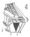
- a vibratory shaker 100is shown.
- a screen 102is detachably secured to vibratory shaker 100. With screen 102 or a plurality of screens secured in place, a tray is formed with the opposed, parallel sidewalls 103 of shaker 100. Drilling mud, along with drill cuttings and debris, is deposited on top of screen 102 at one end. Screen 102 is vibrated at a high frequency or oscillation by a motor or motors for the purpose of screening or separating the drilling mud on screen 102. The liquid and fine particles pass through screen 102 by force of gravity and acceleration caused by the motor and are recovered underneath. Solid particles above a certain size migrate and vibrate across screen 102 where they are discharged.
- Screen 102may include filtering elements attached to a screen frame (not shown). The filtering elements may further define the largest solid particle capable of passing therethrough.
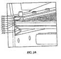
- a screen clamp 200is shown in accordance with embodiments of the present disclosure.
- Screen clamp 200may be attached to an inside wall of a shaker by any method known to those skilled in the art, including, for example, mechanical fasteners and/or welding.
- Screen clamps 200may be used to secure a screen 220 to the shaker, wherein at least one screen clamp 200 is positioned on a side wall of the shaker.
- multiple screen claims 200 disposed on opposing side walls of the shakermay be used to further secure screen 220.
- screen 220may be installed in the shaker by inserting screen 220 in at least two the screen clamps 200.
- screen clamp 200includes a track 202 configured to receive a shaker screen 220, wherein track 202 includes an angled surface 203 (i.e., a downward angled surface along the length of track 202).
- Screen clamp 200further includes an upper retainer 204 positioned above track 202, such that, when installed, screen 220 is disposed between upper retainer 204 and track 202.
- upper retainer 204 and track 202may be joined together by a vertical portion 207.
- track 202, upper retainer 204, and vertical portion 207may be integrally formed as a single component.
- track 202, upper retainer 204, and vertical portion 207may be discrete components, each being independently attached to the shaker.
- Shaker screen 220includes beveled edges 222 that correspond to angled surface 203, and are configured to contact track 202 of screen clamps 200.
- Beveled edges 222 of shaker screen 220may be angled about the same as track 202, or within a given tolerance such that screen 220 may be received by screen clamp 200.
- beveled edges 222 of shaker screen 220may be configured at an angle slightly less than track 202, leaving a small gap at the bottom portion of the contact area.
- beveled edges 222may have an angle greater than track 202, which would leave a small gap at the top portion of the contact area.
- beveled edges 222 of shaker screen 220may be integrally formed as part of shaker screen 220, or in the case of shaker screens already in use, may be attached by means known to those skilled in the art.
- beveled edges 222may be one substantially continuous edge down the length of shaker screen 220, or may be separated into individual smaller surfaces spaced along the of shaker screen 220.
- a seal 206may be attached to upper retainer 204, such that seal 206 is located between a bottom surface 205 of upper retainer 204 and a top surface 221 of shaker screen 220.
- seal 206may be an inflatable seal, elastomer seal, or other seals known to those skilled in the art. Seal 206 may be provided to prevent or reduce debris or fluid from bypassing the shaker screen 220. In some embodiments, as discussed in further detail below, seal 206 may assist in securing shaker screen 220 between upper retainer 204 and track 202.
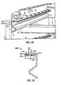
- screen clamp 200is disposed on a shaker 220 and includes a track 202 having an angled surface 203.
- Screen clamp 202further includes an upper retainer 204 and a vertical portion 207.
- Track 202 of screen clamp 200is angled downward at an angle ⁇ , and is configured to contact corresponding beveled edge (222 of FIG. 2A ) of shaker screen 220 when assembled.
- Track 202may be angled at varying degrees, as determined by the requirements of a certain separatory operation.
- track 202may include angle ⁇ ranging between 10° and 50°.
- an optimal track 202may include angle ⁇ of about 30°. Accordingly, beveled edge 222 of shaker screen 220 may include an angle that corresponds to angle ⁇ of track 202, such that beveled edge 222 and track 202 are in substantial alignment. Thus, in one embodiment, beveled edge 222 may include an angle ranging between 10° and 50 ° of horizontal.
- the desired angle ⁇ of track 202may be determined by a number of factors, including, but not limited to, the weight of the shaker screen, shaker screen mesh size, fluid volume, solids particle size, etc.
- track 202 and upper retainer 204may be separate components, as illustrated in FIG. 2C .
- track 202 and upper retainer 204may be attached to shaker 220 as separate components and without a vertical portion.
- Track 202may be configured to provide a seat for the installed shaker screen.
- track 202may be one solid surface disposed along the entire length of screen clamp 200. While track 202 is shown having a triangular cross-section, one of ordinary skill in the art will appreciate that other cross-sectional geometries are possible so long as track 202 includes an angled surface 203 with a downward slope.
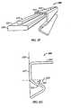
- the angled surface 203 of track 202may also include a curvilinear surface 201, as shown in FIG. 2G .
- the track 202may be angled at varying degrees, as determined by the requirements of a certain separatory operation.
- track 202may include an angle ⁇ ranging between 10° and 50°.
- the curvilinear surface 201 of track 202may be convex or concave, or may include a combination of straight surface sections, convex surface sections, and/or concave surface sections.
- a shaker screen formed in accordance with embodiments disclosed hereinmay include a radiused edge that corresponds to the curvilinear surface 201 of track 202. For example, in one embodiment, as shown in FIG.
- track 402includes a concave curvilinear surface 201 and a shaker screen 420 of the screen clamping assembly may include a convex radiused edge 423, such that when assembled, the shaker screen 420 is aligned with track 402.
- upper retainer 204may be positioned above the shaker screen and configured to reduce movement of the shaker screen in an upward direction, thereby maintaining the screen in a secured position and preventing debris from bypassing the screen.
- upper retainer 204may be disposed along an entire length of screen clamp 200.
- upper retainer 204may include protrusions spaced along the inside wall of the shaker. Exemplary protrusions may include rods disposed on an inside wall of the shaker assembly and configured to extend over at least a portion of the shaker screen.
- Those skilled in the artwill appreciate that alternate configurations for upper retainer 204 may be used without departing from the scope of the embodiments disclosed herein.
- relatively smaller screen clamps 200may be used, such that multiple screen clamps 200 may be disposed on an inside wall of the shaker.
- the multiple screen clamps 200may be spaced along the length of the shaker, so as to receive a screen and hold the screen in place during operation.
- a seal 206 attached to an upper retainer 204 of the screen clamps 200may include a plurality of push buttons 270, or toggles, that protrude through openings formed in the upper retainer 204 of screen clamps 200.
- the plurality of buttons 270are configured to align and secure the seal 206 to the upper retainer 204.
- the seal 206may include an attachment device 230 that is configured to couple the seal 206 to the upper retainer 204.
- the attachment device 230may be coupled to an upper surface 231 of the seal 206 by any means known in the art, including, for example, mechanical fasteners and adhesives.
- the attachment device 230may be integrally formed ( e.g. , a single mold or co-molded) with the seal 206.
- the attachment device 230is disposed along a length of upper surface 231 of the seal 206. In one embodiment, the attachment device 230 extends along the entire length of seal 206.
- the attachment device 230may include one or more smaller attachment devices disposed at select locations along the length of the upper surface 231 of seal 206.
- Upper retainer 204includes a corresponding groove 232 configured to receive attachment device 230, thereby coupling the seal 206 to the screen clamp 200.
- Corresponding groove 232may be integrally formed with upper retainer 204 or may be formed by attaching a groove component 273 to the bottom surface 205 of the upper retainer 204.
- the attachment device 230 and the corresponding groove 232may have a dovetail profile, a bulb profile, or any other profile known in the art, such that the attachment device 230 couples the seal 206 to the upper retainer 204.
- FIG. 3Aan assembly view of a shaker screen 320 during installation is shown in accordance with embodiments of the present disclosure.
- Shaker screen 320is inserted into screen clamps 300, such that beveled edges (not shown) of shaker screen 320 contact tracks 302 of screen clamps 300.
- FIG. 3Ban assembled view of shaker screen 320 is shown in accordance with embodiments of the present disclosure.
- shaker screen 320is fully inserted in screen clamps 300 and seated on tracks 302 of screen clamps 300.
- silicon grease, or other lubricating materialsmay be applied to tracks 302 or to shaker screen 320 to reduce friction and otherwise prevent binding of shaker screen 320.
- FIGS. 3A and 3Bshow one screen 320 inserted into screen clamps 300, one of ordinary skill in the art will appreciate that more than one screen may be inserted and clamped by one or more screen clamps 300 without departing from the scope of the embodiments disclosed herein.
- screen clamp 300When the shaker is not in use, screen clamp 300 may be cleaned by removing shaker screen 320 and exposing track 302. All surfaces of track 302 may be cleaned by manual wiping, via use of a pressure sprayer, with solids removal fluids, or through other methods known to those skilled in the art. Because of the downward angled surfaces, after solids buildup on the tracks is loosened by the cleaning process, the solids may "run" down and off of track 302. In a situations when the solids are "caked on” or are otherwise hard to remove, a scraper (e.g., a wire brush) may be used to facilitate removal of the solids. Once the solids are loosened, the cleaning process as described above may be used to finish removing residual solids from tracks 302. When tracks 302 are sufficiently clean, shaker screen 320 may be re-installed and secured in screen clamps 320.
- a scrapere.g., a wire brush
- sealing element 406is mounted on a bottom surface 405 of an upper retainer 404.
- Sealing element 406may be attached to upper retainer 404 with mechanical fasteners, chemical adhesives, and/or produced through other methods known to those skilled in the art, such as co-molding sealing element 406 with upper retainer 404.
- sealing element 406may be disposed along at least a portion of a perimeter of bottom surface 405 of upper retainer 404.
- sealing element 406may be disposed along at least a portion of a perimeter of a top surface 421 of shaker screen 420, thereby configured to contact upper retainer 404 when screen 420 is installed.
- a fluidmay be injected into inflatable sealing element 406 through an inlet (not shown), thereby inflating inflatable sealing element 406 into sealing contact with top surface 421 of shaker screen 420.
- the fluidmay be a gas (e.g. , air), a liquid, or a gel.
- Inflation of sealing element 406may push shaker screen 420 downward into sealing engagement with track 402 (as specifically illustrated in FIGS. 4B and 4C ).
- inflatable sealing element 406may reduce or prevent leakage of unfiltered drilling fluid over the sides of the shaker screen 420.
- sealing element 406may include one or multiple sealing elements disposed along at least a portion of the perimeter of top or bottom surfaces 404, 405 of shaker screen 400.
- sealing element 406may be formed from any material known in the art including, but not limited to, rubbers, plastics, thermoplastic elastomers ("TPE"), foams, polychloroprene, polypropylene, nylon, mylar, composites, and/or any combinations thereof.
- TPEthermoplastic elastomers
- embodiments of the present disclosuremay improve alignment of screens when installed on shakers.
- the angled surface configuration of the track of the screen clampmay help align a screen by self-centering the screen when the inflatable sealing element pushes down on the screen. Because of the angled surfaces and the weight of the shaker screen, the screen may be positioned so as to reduce lateral movement or the "play" of the screen during operation. The fit of the screen may thus make it less susceptible to vibrations or jolts that could otherwise move it out of alignment. Further, the fit of the screen in the screen clamps may reduce fatigue in both the screen and screen clamps, allowing longer use of the shaker screen.
- the angled geometry of the interfacing surfaces of the track and the screenmay prevent an accumulation of solids on the track.
- solidsmay build-up on conventional tracks if solids or particles bypass a seal.
- the angled surfaces of the screen clamps disclosed hereinmay provide easier solids cleaning because of the downward slope of the angled surface. As such, solids that bypass the screen may "fall out” or slide down the angled surfaces of the tracks more easily.
- Build-up of solids in conventional shakersmay result in screens that are not properly positioned in the tracks.
- a large build-up of solidsmay lead to unwanted shifting of the shaker screen, as well as leaks, lost fluids, and inefficient separatory operations.
- Embodiments of the present disclosuremay prevent or reduce such a build-up of solids, so that the screen may be optimally located within the shaker.
- the screen clampmay provide an attachment device for installing and securing the seal to the screen clamp while only having access to an end ( i.e., discharge end) of the shaker.
Landscapes
- Engineering & Computer Science (AREA)
- Geology (AREA)
- Mining & Mineral Resources (AREA)
- Life Sciences & Earth Sciences (AREA)
- General Life Sciences & Earth Sciences (AREA)
- Fluid Mechanics (AREA)
- Mechanical Engineering (AREA)
- Environmental & Geological Engineering (AREA)
- Physics & Mathematics (AREA)
- Geochemistry & Mineralogy (AREA)
- Combined Means For Separation Of Solids (AREA)
- Paper (AREA)
- Accessories For Mixers (AREA)
- Window Of Vehicle (AREA)
- Apparatus Associated With Microorganisms And Enzymes (AREA)
Description
- Embodiments disclosed herein relate generally to apparatus and methods for securing a shaker screen to a shaker. More specifically, the present disclosure relates to a screen clamp for removeably securing a shaker screen to a shaker.
- Oilfield drilling fluid, often called "mud," serves multiple purposes in the industry. Among its many functions, the drilling mud acts as a lubricant to cool rotary drill bits and facilitate faster cutting rates. Typically, the mud is mixed at the surface and pumped downhole at high pressure to the drill bit through a bore of the drillstring. Once the mud reaches the drill bit, it exits through various nozzles and ports where it lubricates and cools the drill bit. After exiting through the nozzles, the "spent" fluid returns to the surface through an annulus formed between the drillstring and the drilled wellbore.
- Furthermore, drilling mud provides a column of hydrostatic pressure, or head, to prevent "blow out" of the well being drilled. This hydrostatic pressure offsets formation pressures, thereby preventing fluids from blowing out if pressurized deposits in the formation are breached. Two factors contributing to the hydrostatic pressure of the drilling mud column are the height (or depth) of the column (i.e., the vertical distance from the surface to the bottom of the wellbore) itself and the density (or its inverse, specific gravity) of the fluid used. Depending on the type and construction of the formation to be drilled, various weighting and lubrication agents are mixed into the drilling mud to obtain the right mixture. Typically, drilling mud weight is reported in "pounds," short for pounds per gallon. Generally, increasing the amount of weighting agent solute dissolved in the mud base will create a heavier drilling mud. Drilling mud that is too light may not protect the formation from blow outs, and drilling mud that is too heavy may over invade the formation. Therefore, much time and consideration is spent to ensure the mud mixture is optimal. Because the mud evaluation and mixture process is time consuming and expensive, drillers and service companies prefer to reclaim the returned drilling mud and recycle it for continued use.
- Another significant purpose of the drilling mud is to carry the cuttings away from the drill bit at the bottom of the borehole to the surface. As a drill bit pulverizes or scrapes the rock formation at the bottom of the borehole, small pieces of solid material are left behind. The drilling fluid exiting the nozzles at the bit acts to stir-up and carry the solid particles of rock and formation to the surface within the annulus between the drillstring and the borehole. Therefore, the fluid exiting the borehole from the annulus is a slurry of formation cuttings in drilling mud. Before the mud can be recycled and re-pumped down through nozzles of the drill bit, the cutting particulates must be removed.
- Generally, a shaker screen assembly is disposed on a screen deck of a shaker. Over time, solids may collect or build up on a surface of the screen deck. The solids build-up may prevent the shaker screen from being properly seated and/or aligned in the shaker. Accordingly, there exists a need for a mechanism to secure a screen in a shaker that reduces the build up of solids in its tracks.
- Document
US-A-2006/219608 describes interconnectible screen assemblies for vibratory separators or shale shakers and methods for manipulating such screen assemblies which include a first screen assembly and a second screen assembly positioning at least a portion of the first screen assembly with respect to the second screen assembly, releasably connecting the second screen assembly to the first screen assembly, and moving the first screen assembly and the second screen assembly together. - Document
US-A-5615776 describes a withdrawable lower fine mesh screen assembly, in a vibratory screening apparatus, having a screen unit releasably mounted on a grid/frame structure. The screen unit has a sheet of mesh material bonded to a grate or lattice of a yieldable material such as a hard rubber, and this lattice and the edges of the mesh are also fixed to relatively rigid side members which are mutually free each from the others. In the structure, a rigid grate of support bars supports the lattice with a sliding contact interface, and a frame incorporates pneumatically actuated tensioners and clamps respectively for tensioning/locking the screen unit and coupling the screen assembly to the vibratory structure. - Document
US-A-4137157 describes a screen tensioning assembly for vibratory, particulate material-screening apparatus of the type including a frame having spaced, parallel, upstanding side panels connected by spaced, horizontal screen support members, and two, extended area apertured screens supported on the support members and extending substantially between the side panels for separating fmer from coarser material. An up-turned hook portion is formed at one side of each of the screens. Each of the screens is tensioned by a clamping member having opposite ends with one end normally engaging the respective hook portion and the other end engaging the respective side panel. Each clamping member has a pivot member secured thereto adjacent its other end, extending through an aperture in the respective side panel, and having a portion engaging the respective side panel so that the clamping member may be pivoted upwardly from the respective screen to a stored position thereby to disengage the one end thereof from the respective hook portion. Each clamping member has one end of a stud connected thereto with its other end extending through another aperture in the respective side panel. The two screens have adjacent side edges which define an elongated, narrow space therebetween intermediate and parallel with the side panels. Down-turned hook portions are respectively formed at the adjacent side edges of the screens and respectively engage upstanding elements on the support members. - Document
WO-A-2004/069374 describes a screen system suitable for use in a vibratory screen apparatus comprising: a screen element consisting essentially of a mesh panel provided with first and second elongate support members extending along opposite end portions; and a support frame therefor. The support frame has spaced apart first and second elongate frame elements for engagement with said screen element support members and further elongate frame elements extending between the first and second frame elements for supporting the mesh panel. The support frame is provided with at least one mesh panel support provided with an elevating support surface, which tensions the screen element across the support surface and between the screen element support members. - In one aspect, the invention is related to a screen clamp as defined in
claim 1 including a track configured to secure a screen to a shaker, the track including an angled surface configured to contact a corresponding beveled edge of a shaker screen. The screen clamp further includes an upper retainer configured to extend from an inner wall of the shaker over at least a portion of the screen. - In another aspect, embodiments of the present disclosure relate to a screen clamping assembly including a screen comprising beveled edges along at least a lower perimeter, and at least two screen clamps according to the first aspect disposed on the inside walls of the shaker.
- In another aspect, the invention is related to a method as defined in claim 13 to secure a shaker screen, the method including installing the shaker screen into at least two screen clamps attached to an inside wall of a shaker, wherein the installing includes aligning beveled edges of the shaker screen with angled surfaces of the screen clamps.
- Other aspects and advantages of the invention will be apparent from the following description and the appended claims.
FIG. 1 shows a conventional shaker apparatus.FIG. 2A shows an assembly view of a screen clamp in accordance with embodiments of the present disclosure.FIG. 2B shows a cross-sectional view of a screen clamp in accordance with embodiments of the present disclosure, with the seal omitted.FIG. 2C shows a cross-sectional view of a screen clamp in accordance with alternate embodiments of the present disclosure, with the seal omitted.FIG. 2D shows a cross-sectional view of a screen clamp in accordance with embodiments of the present disclosure.FIG. 2E shows a cross-sectional view of a screen clamp in accordance with embodiments of the present disclosure.FIG. 2F shows a perspective view of the screen clamp ofFIG. 2E in accordance with embodiments of the present disclosure.FIG. 2G shows a cross-sectional view of a screen clamp in accordance with embodiments of the present disclosure, with the seal omitted.FIG. 3A shows an assembly view of an installation of a shaker screen into screen clamps in accordance with embodiments of the present disclosure.FIG. 3B shows an assembly view of a completed installation of a shaker screen into screen clamps in accordance with embodiments of the present disclosure.FIG. 4A shows an end view of a screen clamp before inflation of a seal assembly in accordance with embodiments of the present disclosure.FIG. 4B shows an end view of a screen clamp after inflation of a seal assembly in accordance with embodiments of the present disclosure.FIG. 4C shows an end view of a screen clamp after inflation of a seal assembly in accordance with embodiments of the present disclosure.- In one aspect, embodiments disclosed herein relate to apparatus and methods for securing a shaker screen to a shaker. In particular, the present disclosure relates to a screen clamp for a shaker screen.
- Referring to
FIG. 1 , avibratory shaker 100 is shown. As shown, ascreen 102 is detachably secured tovibratory shaker 100. Withscreen 102 or a plurality of screens secured in place, a tray is formed with the opposed,parallel sidewalls 103 ofshaker 100. Drilling mud, along with drill cuttings and debris, is deposited on top ofscreen 102 at one end.Screen 102 is vibrated at a high frequency or oscillation by a motor or motors for the purpose of screening or separating the drilling mud onscreen 102. The liquid and fine particles pass throughscreen 102 by force of gravity and acceleration caused by the motor and are recovered underneath. Solid particles above a certain size migrate and vibrate acrossscreen 102 where they are discharged.Screen 102 may include filtering elements attached to a screen frame (not shown). The filtering elements may further define the largest solid particle capable of passing therethrough. - Referring to
FIG. 2A , ascreen clamp 200 is shown in accordance with embodiments of the present disclosure.Screen clamp 200 may be attached to an inside wall of a shaker by any method known to those skilled in the art, including, for example, mechanical fasteners and/or welding. Screen clamps 200 may be used to secure ascreen 220 to the shaker, wherein at least onescreen clamp 200 is positioned on a side wall of the shaker. In certain embodiments, multiple screen claims 200 disposed on opposing side walls of the shaker may be used to furthersecure screen 220. Thus,screen 220 may be installed in the shaker by insertingscreen 220 in at least two the screen clamps 200. - Generally,
screen clamp 200 includes atrack 202 configured to receive ashaker screen 220, whereintrack 202 includes an angled surface 203 (i.e., a downward angled surface along the length of track 202).Screen clamp 200 further includes anupper retainer 204 positioned abovetrack 202, such that, when installed,screen 220 is disposed betweenupper retainer 204 andtrack 202. In certain embodiments,upper retainer 204 and track 202 may be joined together by avertical portion 207. In such embodiments,track 202,upper retainer 204, andvertical portion 207 may be integrally formed as a single component. Alternatively,track 202,upper retainer 204, andvertical portion 207 may be discrete components, each being independently attached to the shaker. Shaker screen 220 includes beveled edges 222 that correspond toangled surface 203, and are configured to contacttrack 202 of screen clamps 200. Beveled edges 222 ofshaker screen 220 may be angled about the same astrack 202, or within a given tolerance such thatscreen 220 may be received byscreen clamp 200. In certain embodiments, beveled edges 222 ofshaker screen 220 may be configured at an angle slightly less thantrack 202, leaving a small gap at the bottom portion of the contact area. Alternatively, beveled edges 222 may have an angle greater thantrack 202, which would leave a small gap at the top portion of the contact area. Furthermore, beveled edges 222 ofshaker screen 220 may be integrally formed as part ofshaker screen 220, or in the case of shaker screens already in use, may be attached by means known to those skilled in the art.- As illustrated, beveled edges 222 may be one substantially continuous edge down the length of
shaker screen 220, or may be separated into individual smaller surfaces spaced along the ofshaker screen 220. Still referring toFIG. 2A , aseal 206 may be attached toupper retainer 204, such thatseal 206 is located between abottom surface 205 ofupper retainer 204 and atop surface 221 ofshaker screen 220. In certain embodiments,seal 206 may be an inflatable seal, elastomer seal, or other seals known to those skilled in the art.Seal 206 may be provided to prevent or reduce debris or fluid from bypassing theshaker screen 220. In some embodiments, as discussed in further detail below,seal 206 may assist in securingshaker screen 220 betweenupper retainer 204 andtrack 202. - Referring now to
FIG. 2B , a cross-sectional view of ascreen clamp 200 in accordance with embodiments of the present disclosure is shown. As described above,screen clamp 200 is disposed on ashaker 220 and includes atrack 202 having anangled surface 203.Screen clamp 202 further includes anupper retainer 204 and avertical portion 207.Track 202 ofscreen clamp 200 is angled downward at an angle α, and is configured to contact corresponding beveled edge (222 ofFIG. 2A ) ofshaker screen 220 when assembled.Track 202 may be angled at varying degrees, as determined by the requirements of a certain separatory operation. In one embodiment, track 202 may include angle α ranging between 10° and 50°. In certain embodiments, anoptimal track 202 may include angle α of about 30°. Accordingly, beveled edge 222 ofshaker screen 220 may include an angle that corresponds to angle α oftrack 202, such that beveled edge 222 and track 202 are in substantial alignment. Thus, in one embodiment, beveled edge 222 may include an angle ranging between 10° and 50 ° of horizontal. - The desired angle α of
track 202, and thus the corresponding angle of beveled edge 222, may be determined by a number of factors, including, but not limited to, the weight of the shaker screen, shaker screen mesh size, fluid volume, solids particle size, etc. In certain embodiments,track 202 andupper retainer 204 may be separate components, as illustrated inFIG. 2C . In this embodiment,track 202 andupper retainer 204 may be attached toshaker 220 as separate components and without a vertical portion. Track 202 may be configured to provide a seat for the installed shaker screen. In one embodiment, track 202 may be one solid surface disposed along the entire length ofscreen clamp 200. Whiletrack 202 is shown having a triangular cross-section, one of ordinary skill in the art will appreciate that other cross-sectional geometries are possible so long astrack 202 includes anangled surface 203 with a downward slope.- In certain embodiments, the
angled surface 203 oftrack 202 may also include acurvilinear surface 201, as shown inFIG. 2G . In this embodiment, thetrack 202 may be angled at varying degrees, as determined by the requirements of a certain separatory operation. As discussed above, track 202 may include an angle α ranging between 10° and 50°. Thecurvilinear surface 201 oftrack 202 may be convex or concave, or may include a combination of straight surface sections, convex surface sections, and/or concave surface sections. A shaker screen formed in accordance with embodiments disclosed herein may include a radiused edge that corresponds to thecurvilinear surface 201 oftrack 202. For example, in one embodiment, as shown inFIG. 4C ,track 402 includes a concavecurvilinear surface 201 and ashaker screen 420 of the screen clamping assembly may include a convexradiused edge 423, such that when assembled, theshaker screen 420 is aligned withtrack 402. - Referring generally to
Figures 2A-2G ,upper retainer 204 may be positioned above the shaker screen and configured to reduce movement of the shaker screen in an upward direction, thereby maintaining the screen in a secured position and preventing debris from bypassing the screen. In certain embodiments,upper retainer 204 may be disposed along an entire length ofscreen clamp 200. In other embodiments,upper retainer 204 may include protrusions spaced along the inside wall of the shaker. Exemplary protrusions may include rods disposed on an inside wall of the shaker assembly and configured to extend over at least a portion of the shaker screen. Those skilled in the art will appreciate that alternate configurations forupper retainer 204 may be used without departing from the scope of the embodiments disclosed herein. - In certain embodiments, relatively smaller screen clamps 200 may be used, such that multiple screen clamps 200 may be disposed on an inside wall of the shaker. In such an embodiment, the multiple screen clamps 200 may be spaced along the length of the shaker, so as to receive a screen and hold the screen in place during operation.
- As shown in
FIG. 2D , aseal 206 attached to anupper retainer 204 of the screen clamps 200 may include a plurality ofpush buttons 270, or toggles, that protrude through openings formed in theupper retainer 204 of screen clamps 200. The plurality ofbuttons 270 are configured to align and secure theseal 206 to theupper retainer 204. - In alternate embodiments, as shown in
FIGS. 2E and2F , theseal 206 may include anattachment device 230 that is configured to couple theseal 206 to theupper retainer 204. In one embodiment, theattachment device 230 may be coupled to anupper surface 231 of theseal 206 by any means known in the art, including, for example, mechanical fasteners and adhesives. Alternatively, theattachment device 230 may be integrally formed (e.g., a single mold or co-molded) with theseal 206. As shown inFIG. 2F , theattachment device 230 is disposed along a length ofupper surface 231 of theseal 206. In one embodiment, theattachment device 230 extends along the entire length ofseal 206. In alternate embodiments, theattachment device 230 may include one or more smaller attachment devices disposed at select locations along the length of theupper surface 231 ofseal 206.Upper retainer 204 includes acorresponding groove 232 configured to receiveattachment device 230, thereby coupling theseal 206 to thescreen clamp 200.Corresponding groove 232 may be integrally formed withupper retainer 204 or may be formed by attaching agroove component 273 to thebottom surface 205 of theupper retainer 204. One skilled in the art will appreciate that theattachment device 230 and thecorresponding groove 232 may have a dovetail profile, a bulb profile, or any other profile known in the art, such that theattachment device 230 couples theseal 206 to theupper retainer 204. - Referring to
FIG. 3A , an assembly view of ashaker screen 320 during installation is shown in accordance with embodiments of the present disclosure.Shaker screen 320 is inserted into screen clamps 300, such that beveled edges (not shown) ofshaker screen 320contact tracks 302 of screen clamps 300. Referring toFIG. 3B , an assembled view ofshaker screen 320 is shown in accordance with embodiments of the present disclosure. When assembled,shaker screen 320 is fully inserted in screen clamps 300 and seated ontracks 302 of screen clamps 300. During installation, silicon grease, or other lubricating materials may be applied totracks 302 or toshaker screen 320 to reduce friction and otherwise prevent binding ofshaker screen 320. WhileFIGS. 3A and3B show onescreen 320 inserted into screen clamps 300, one of ordinary skill in the art will appreciate that more than one screen may be inserted and clamped by one or more screen clamps 300 without departing from the scope of the embodiments disclosed herein. - When the shaker is not in use,
screen clamp 300 may be cleaned by removingshaker screen 320 and exposingtrack 302. All surfaces oftrack 302 may be cleaned by manual wiping, via use of a pressure sprayer, with solids removal fluids, or through other methods known to those skilled in the art. Because of the downward angled surfaces, after solids buildup on the tracks is loosened by the cleaning process, the solids may "run" down and off oftrack 302. In a situations when the solids are "caked on" or are otherwise hard to remove, a scraper (e.g., a wire brush) may be used to facilitate removal of the solids. Once the solids are loosened, the cleaning process as described above may be used to finish removing residual solids fromtracks 302. When tracks 302 are sufficiently clean,shaker screen 320 may be re-installed and secured in screen clamps 320. - Referring to
FIGS. 4A-4C together, end views ofshaker screen 420 inserted intoscreen clamp 400 with a sealingelement 406 in accordance with embodiments of the present disclosure are shown. In this embodiment, sealingelement 406 is mounted on abottom surface 405 of anupper retainer 404.Sealing element 406 may be attached toupper retainer 404 with mechanical fasteners, chemical adhesives, and/or produced through other methods known to those skilled in the art, such asco-molding sealing element 406 withupper retainer 404. In one embodiment, sealingelement 406 may be disposed along at least a portion of a perimeter ofbottom surface 405 ofupper retainer 404. In alternate embodiments, sealingelement 406 may be disposed along at least a portion of a perimeter of atop surface 421 ofshaker screen 420, thereby configured to contactupper retainer 404 whenscreen 420 is installed. - During operation, a fluid may be injected into
inflatable sealing element 406 through an inlet (not shown), thereby inflatinginflatable sealing element 406 into sealing contact withtop surface 421 ofshaker screen 420. One of ordinary skill in the art will appreciate that the fluid may be a gas (e.g., air), a liquid, or a gel. Inflation of sealingelement 406 may pushshaker screen 420 downward into sealing engagement with track 402 (as specifically illustrated inFIGS. 4B and 4C ). Thus, the need for typical wedge blocks and/or other screen securing mechanisms may be eliminated. Additionally,inflatable sealing element 406 may reduce or prevent leakage of unfiltered drilling fluid over the sides of theshaker screen 420. An inflatable sealing mechanism that may be used with embodiments disclosed herein is described in United States Patent Application Serial No.11/860,479 - One of ordinary skill in the art will appreciate that in one embodiment, sealing
element 406 may include one or multiple sealing elements disposed along at least a portion of the perimeter of top orbottom surfaces shaker screen 400. Furthermore, sealingelement 406 may be formed from any material known in the art including, but not limited to, rubbers, plastics, thermoplastic elastomers ("TPE"), foams, polychloroprene, polypropylene, nylon, mylar, composites, and/or any combinations thereof. - Advantageously, embodiments of the present disclosure may improve alignment of screens when installed on shakers. The angled surface configuration of the track of the screen clamp may help align a screen by self-centering the screen when the inflatable sealing element pushes down on the screen. Because of the angled surfaces and the weight of the shaker screen, the screen may be positioned so as to reduce lateral movement or the "play" of the screen during operation. The fit of the screen may thus make it less susceptible to vibrations or jolts that could otherwise move it out of alignment. Further, the fit of the screen in the screen clamps may reduce fatigue in both the screen and screen clamps, allowing longer use of the shaker screen.
- Additionally, the angled geometry of the interfacing surfaces of the track and the screen may prevent an accumulation of solids on the track. In some instances, solids may build-up on conventional tracks if solids or particles bypass a seal. Moreover, as opposed to typical horizontal shelf-type screen supports, the angled surfaces of the screen clamps disclosed herein may provide easier solids cleaning because of the downward slope of the angled surface. As such, solids that bypass the screen may "fall out" or slide down the angled surfaces of the tracks more easily. Build-up of solids in conventional shakers may result in screens that are not properly positioned in the tracks. Furthermore, a large build-up of solids may lead to unwanted shifting of the shaker screen, as well as leaks, lost fluids, and inefficient separatory operations. Embodiments of the present disclosure may prevent or reduce such a build-up of solids, so that the screen may be optimally located within the shaker.
- Furthermore, embodiments of the present disclosure may advantageously provide features that allow components to be more easily replaced and installed during operation. Specifically, the screen clamp may provide an attachment device for installing and securing the seal to the screen clamp while only having access to an end (i.e., discharge end) of the shaker.
- While the present disclosure has been described with respect to a limited number of embodiments, those skilled in the art, having benefit of this disclosure, will appreciate that other embodiments may be devised which do not depart from the scope of the attached claims.
Claims (15)
- A screen clamp (200, 300, 400) comprising:a track (202, 302, 402) configured to be attached to an inside wall of a shaker and configured to slidingly receive a shaker screen (220, 320, 420), the track (202, 302, 402) comprising:a downward angled surface (203) configured to contact a corresponding edge (222, 423) of a bottom surface of the shaker screen (220, 320, 420);an upper retainer (204, 404) configured to be attached to an inside wall of the shaker and configured to extend from the inside wall of the shaker over at least a portion of a top surface (221, 421) of the shaker screen (220, 320, 420); anda seal (206, 406) mounted on a bottom surface (205, 405) of the upper retainer (204, 404), the seal (206, 406) being configured to contact a top surface (221, 421) of the shaker screen (220, 320, 420).
- The clamp (200, 300, 400) of claim 1, further comprising an attachment device (230) configured to couple the seal (206, 406) with the upper retainer (204, 404).
- The clamp (200, 300, 400) of claim 2, wherein the upper retainer (204, 404) comprises a groove (232) configured to receive the attachment device (230).
- The clamp (200, 300, 400) of claim 3, wherein the groove (232) extends along a length of the upper retainer (204, 404) and the attachment device (230) extends along a length of the seal (206, 406).
- The clamp (200, 300, 400) of claim 3, wherein the groove (232) and attachment device (230) include a dovetail profile when assembled.
- The clamp (200, 300, 400) of claim 1, wherein an angle of the track (202, 302, 402) comprises a range between 10° and 50° from horizontal.
- The clamp (200, 300, 400) of claim 1, wherein the seal (206, 406) comprise an inflatable seal.
- The clamp (200, 300, 400) of claim 1, wherein the track (202, 302, 402) and the upper retainer (204, 404) are integrally formed.
- The clamp (200, 300 400) of claim 8, wherein a vertical portion (207) connects the track (202, 302, 402) and the upper retainer (204, 404).
- The clamp (200, 300, 400) of claim 1, wherein the angled surface (203) of the track (202, 302, 402) comprises a curvilinear surface (201) configured to contact a corresponding radiused edge (423) of the shaker screen (220, 320, 420).
- A screen clamping assembly comprising:a shaker screen (220, 320, 420) comprising beveled edges (222) along at least a lower perimeter; andat least two screen clamps (200, 300, 400) according to any of claims 1-9.
- The screen clamping assembly of claim 11, wherein the edge (222) of the shaker screen (220, 320, 420) is beveled and comprises a range between 10° and 50° from horizontal.
- A method of installing a shaker screen (220, 320, 420), the method comprising:sliding the shaker screen (220, 320, 420) having at least one beveled edge (222) on a bottom surface into a screen clamp (200, 300, 400) attached to an inside wall of a shaker, the screen clamp (200, 300, 400) having:a track (202, 302, 402) configured to slidingly receive the shaker screen (220, 320, 420), the track (202, 302, 402) comprising a downward angled surface (203),an upper retainer (204, 404) configured to extend from the inside wall of the shaker over at least a portion of a top surface (221, 421) of the shaker screen (220, 320, 420) anda seal (206, 406) mounted on a bottom surface (205, 405) of the upper retainer (204, 404); andcontacting a top surface (221, 421) of the shaker screen (220, 320, 420) with the seal (206, 406).
- The method of claim 13, further comprising:inflating the seal (206, 406) disposed on the upper retainer (204, 404).
- The method of claim 14, further comprising:providing a downward force on the shaker screen (220, 320, 420).
Priority Applications (1)
| Application Number | Priority Date | Filing Date | Title |
|---|---|---|---|
| PL08835955TPL2209566T3 (en) | 2007-10-05 | 2008-10-01 | Screen clamp |
Applications Claiming Priority (3)
| Application Number | Priority Date | Filing Date | Title |
|---|---|---|---|
| US97787507P | 2007-10-05 | 2007-10-05 | |
| US3441108P | 2008-03-06 | 2008-03-06 | |
| PCT/US2008/078403WO2009046071A2 (en) | 2007-10-05 | 2008-10-01 | Screen clamp |
Publications (2)
| Publication Number | Publication Date |
|---|---|
| EP2209566A2 EP2209566A2 (en) | 2010-07-28 |
| EP2209566B1true EP2209566B1 (en) | 2012-11-21 |
Family
ID=40409960
Family Applications (1)
| Application Number | Title | Priority Date | Filing Date |
|---|---|---|---|
| EP08835955AActiveEP2209566B1 (en) | 2007-10-05 | 2008-10-01 | Screen clamp |
Country Status (10)
| Country | Link |
|---|---|
| US (1) | US8561804B2 (en) |
| EP (1) | EP2209566B1 (en) |
| CN (1) | CN101821021B (en) |
| AR (1) | AR068687A1 (en) |
| BR (1) | BRPI0817519B1 (en) |
| CA (1) | CA2701730C (en) |
| EA (1) | EA016036B1 (en) |
| MX (1) | MX2010003665A (en) |
| PL (1) | PL2209566T3 (en) |
| WO (1) | WO2009046071A2 (en) |
Families Citing this family (15)
| Publication number | Priority date | Publication date | Assignee | Title |
|---|---|---|---|---|
| EP2209566B1 (en)* | 2007-10-05 | 2012-11-21 | M-I Llc | Screen clamp |
| US20100195084A1 (en)* | 2009-02-03 | 2010-08-05 | Wkk Distribution, Ltd. | Substrate holding platen with high speed vacuum |
| MX2013014482A (en)* | 2011-06-09 | 2014-03-27 | Mi Llc | Self clamping shaker screens. |
| US8827080B2 (en)* | 2012-11-08 | 2014-09-09 | M-I L.L.C. | Single side screen clamping |
| CA2911193C (en)* | 2013-05-09 | 2019-01-08 | M-I Llc | Seal with support member |
| WO2016037620A1 (en)* | 2014-09-09 | 2016-03-17 | GEA Scan-Vibro A/S | A sieve apparatus and method of providing a sanitary support for a screen mesh of a sieve apparatus |
| CN105696957A (en)* | 2016-03-31 | 2016-06-22 | 濮阳市共振石油机械有限公司 | Multilayer drilling fluid vibrating screen capable of performing series-parallel connection switching |
| US20170320096A1 (en)* | 2016-05-03 | 2017-11-09 | M-I Llc | Apparatus, system and method for installing a screen assembly in a gyratory sifter |
| CN106198265B (en)* | 2016-07-05 | 2019-03-19 | 中国航空工业集团公司北京航空材料研究院 | A kind of partition part testing fatigue experimental rig and test method |
| CN109173515A (en)* | 2018-11-08 | 2019-01-11 | 福建省南安市环态机械有限公司 | Convenient for the dust collector of filtering layer replacement |
| US11077465B2 (en)* | 2019-06-27 | 2021-08-03 | Schlumberger Technology Corporation | Screen assembly for a vibratory separator |
| EP3785811A1 (en)* | 2019-08-27 | 2021-03-03 | Metso Minerals, Inc. | Screening device |
| CN111974676A (en)* | 2020-09-04 | 2020-11-24 | 北京兴华汇杰科技有限公司 | A screen fixing device |
| WO2023196019A1 (en)* | 2022-04-04 | 2023-10-12 | Brett Herrington | Shaker screen retention rail and channel system |
| WO2024006459A1 (en)* | 2022-06-30 | 2024-01-04 | 7Dynamics, Llc | Pneumo-seal connector for use in a shale shaker |
Family Cites Families (13)
| Publication number | Priority date | Publication date | Assignee | Title |
|---|---|---|---|---|
| GB406474A (en)* | 1933-02-22 | 1934-03-01 | William Norman Barker | Improvements relating to sorting screens, sieves, or riddles |
| DE2504069C2 (en)* | 1975-01-31 | 1985-09-12 | Gebr.Claas Maschinenfabrik GmbH, 4834 Harsewinkel | Mounting frame for conveyor and / or sieve floors of self-propelled combine harvesters |
| US4137157A (en)* | 1976-10-12 | 1979-01-30 | Deister Machine Company, Inc. | Screen tension assembly for vibratory screening apparatus |
| NO170199C (en)* | 1985-06-13 | 1992-09-23 | United Wire Ltd | PROCEDURE FOR RELEASABLE FIXING OF A VIEW ELEMENT IN A HOLDER IN A VIBRATION VIEWING APPARATUS, AND VIBRATION VIEWING APPLIANCE WHICH SUCH A VIEWING ELEMENT CAN BE INSTALLED IN |
| US5615776A (en)* | 1992-04-21 | 1997-04-01 | Alfa Laval Separation Ab | Mounting & tensioning arrangements for screens |
| DE69827046T2 (en) | 1997-03-01 | 2005-03-03 | United Wire Ltd. | Device for repairing or processing a filter screen |
| US7063214B2 (en)* | 2003-02-04 | 2006-06-20 | Varco I/P, Inc. | Interlocking screens for vibratory separators |
| US20060219608A1 (en)* | 2003-02-04 | 2006-10-05 | Eric Scott | Connected screens for vibratory separators |
| GB0302927D0 (en)* | 2003-02-08 | 2003-03-12 | Axiom Process Ltd | Screen mounting system |
| US20110036759A1 (en)* | 2005-12-06 | 2011-02-17 | Rotex, Inc. | Screening machine and associated screen panel |
| US20070125688A1 (en)* | 2005-12-06 | 2007-06-07 | Rotex, Inc. | Screening machine, associated screen panel and seal |
| US7909172B2 (en) | 2006-09-29 | 2011-03-22 | M-I L.L.C. | Composite screen with integral inflatable seal |
| EP2209566B1 (en)* | 2007-10-05 | 2012-11-21 | M-I Llc | Screen clamp |
- 2008
- 2008-10-01EPEP08835955Apatent/EP2209566B1/enactiveActive
- 2008-10-01CNCN200880110319.2Apatent/CN101821021B/enactiveActive
- 2008-10-01BRBRPI0817519-5Apatent/BRPI0817519B1/enactiveSearch and Examination
- 2008-10-01CACA2701730Apatent/CA2701730C/enactiveActive
- 2008-10-01WOPCT/US2008/078403patent/WO2009046071A2/enactiveApplication Filing
- 2008-10-01EAEA201070433Apatent/EA016036B1/ennot_activeIP Right Cessation
- 2008-10-01MXMX2010003665Apatent/MX2010003665A/enactiveIP Right Grant
- 2008-10-01PLPL08835955Tpatent/PL2209566T3/enunknown
- 2008-10-01USUS12/681,020patent/US8561804B2/enactiveActive
- 2008-10-06ARARP080104366Apatent/AR068687A1/enactiveIP Right Grant
Also Published As
| Publication number | Publication date |
|---|---|
| WO2009046071A3 (en) | 2009-07-30 |
| AR068687A1 (en) | 2009-11-25 |
| PL2209566T3 (en) | 2013-06-28 |
| US8561804B2 (en) | 2013-10-22 |
| CA2701730C (en) | 2013-11-19 |
| CN101821021B (en) | 2015-12-16 |
| WO2009046071A2 (en) | 2009-04-09 |
| MX2010003665A (en) | 2010-06-02 |
| US20100236995A1 (en) | 2010-09-23 |
| EA016036B1 (en) | 2012-01-30 |
| CA2701730A1 (en) | 2009-04-09 |
| CN101821021A (en) | 2010-09-01 |
| EA201070433A1 (en) | 2010-10-29 |
| EP2209566A2 (en) | 2010-07-28 |
| BRPI0817519A2 (en) | 2015-03-31 |
| BRPI0817519B1 (en) | 2019-09-24 |
Similar Documents
| Publication | Publication Date | Title |
|---|---|---|
| EP2209566B1 (en) | Screen clamp | |
| US7753213B2 (en) | Composite screen | |
| US7909172B2 (en) | Composite screen with integral inflatable seal | |
| CA2664331C (en) | Magnetic screen clamping | |
| AU2007303610B2 (en) | Sealing system for pre-tensioned composite screens | |
| EP2081698B1 (en) | Screen for a vibratory separator | |
| US20100270215A1 (en) | Vibratory separator screen attachment | |
| EP2718539A2 (en) | Self clamping shaker screens | |
| CA2911193C (en) | Seal with support member | |
| WO2023196019A1 (en) | Shaker screen retention rail and channel system |
Legal Events
| Date | Code | Title | Description |
|---|---|---|---|
| PUAI | Public reference made under article 153(3) epc to a published international application that has entered the european phase | Free format text:ORIGINAL CODE: 0009012 | |
| 17P | Request for examination filed | Effective date:20100505 | |
| AK | Designated contracting states | Kind code of ref document:A2 Designated state(s):AT BE BG CH CY CZ DE DK EE ES FI FR GB GR HR HU IE IS IT LI LT LU LV MC MT NL NO PL PT RO SE SI SK TR | |
| AX | Request for extension of the european patent | Extension state:AL BA MK RS | |
| 17Q | First examination report despatched | Effective date:20110722 | |
| GRAJ | Information related to disapproval of communication of intention to grant by the applicant or resumption of examination proceedings by the epo deleted | Free format text:ORIGINAL CODE: EPIDOSDIGR1 | |
| GRAP | Despatch of communication of intention to grant a patent | Free format text:ORIGINAL CODE: EPIDOSNIGR1 | |
| GRAP | Despatch of communication of intention to grant a patent | Free format text:ORIGINAL CODE: EPIDOSNIGR1 | |
| RIC1 | Information provided on ipc code assigned before grant | Ipc:E21B 21/06 20060101ALI20120615BHEP Ipc:B01D 33/03 20060101ALI20120615BHEP Ipc:B07B 1/46 20060101AFI20120615BHEP | |
| DAX | Request for extension of the european patent (deleted) | ||
| RAP1 | Party data changed (applicant data changed or rights of an application transferred) | Owner name:M-I LLC | |
| GRAS | Grant fee paid | Free format text:ORIGINAL CODE: EPIDOSNIGR3 | |
| GRAA | (expected) grant | Free format text:ORIGINAL CODE: 0009210 | |
| AK | Designated contracting states | Kind code of ref document:B1 Designated state(s):AT BE BG CH CY CZ DE DK EE ES FI FR GB GR HR HU IE IS IT LI LT LU LV MC MT NL NO PL PT RO SE SI SK TR | |
| REG | Reference to a national code | Ref country code:GB Ref legal event code:FG4D | |
| REG | Reference to a national code | Ref country code:CH Ref legal event code:EP | |
| REG | Reference to a national code | Ref country code:AT Ref legal event code:REF Ref document number:584762 Country of ref document:AT Kind code of ref document:T Effective date:20121215 | |
| REG | Reference to a national code | Ref country code:IE Ref legal event code:FG4D | |
| REG | Reference to a national code | Ref country code:DE Ref legal event code:R096 Ref document number:602008020322 Country of ref document:DE Effective date:20130117 | |
| REG | Reference to a national code | Ref country code:RO Ref legal event code:EPE | |
| REG | Reference to a national code | Ref country code:NL Ref legal event code:T3 | |
| REG | Reference to a national code | Ref country code:AT Ref legal event code:MK05 Ref document number:584762 Country of ref document:AT Kind code of ref document:T Effective date:20121121 | |
| REG | Reference to a national code | Ref country code:NO Ref legal event code:T2 Effective date:20121121 | |
| REG | Reference to a national code | Ref country code:LT Ref legal event code:MG4D | |
| PG25 | Lapsed in a contracting state [announced via postgrant information from national office to epo] | Ref country code:LT Free format text:LAPSE BECAUSE OF FAILURE TO SUBMIT A TRANSLATION OF THE DESCRIPTION OR TO PAY THE FEE WITHIN THE PRESCRIBED TIME-LIMIT Effective date:20121121 Ref country code:SE Free format text:LAPSE BECAUSE OF FAILURE TO SUBMIT A TRANSLATION OF THE DESCRIPTION OR TO PAY THE FEE WITHIN THE PRESCRIBED TIME-LIMIT Effective date:20121121 Ref country code:FI Free format text:LAPSE BECAUSE OF FAILURE TO SUBMIT A TRANSLATION OF THE DESCRIPTION OR TO PAY THE FEE WITHIN THE PRESCRIBED TIME-LIMIT Effective date:20121121 Ref country code:ES Free format text:LAPSE BECAUSE OF FAILURE TO SUBMIT A TRANSLATION OF THE DESCRIPTION OR TO PAY THE FEE WITHIN THE PRESCRIBED TIME-LIMIT Effective date:20130304 | |
| PG25 | Lapsed in a contracting state [announced via postgrant information from national office to epo] | Ref country code:SI Free format text:LAPSE BECAUSE OF FAILURE TO SUBMIT A TRANSLATION OF THE DESCRIPTION OR TO PAY THE FEE WITHIN THE PRESCRIBED TIME-LIMIT Effective date:20121121 Ref country code:PT Free format text:LAPSE BECAUSE OF FAILURE TO SUBMIT A TRANSLATION OF THE DESCRIPTION OR TO PAY THE FEE WITHIN THE PRESCRIBED TIME-LIMIT Effective date:20130321 Ref country code:GR Free format text:LAPSE BECAUSE OF FAILURE TO SUBMIT A TRANSLATION OF THE DESCRIPTION OR TO PAY THE FEE WITHIN THE PRESCRIBED TIME-LIMIT Effective date:20130222 Ref country code:BE Free format text:LAPSE BECAUSE OF FAILURE TO SUBMIT A TRANSLATION OF THE DESCRIPTION OR TO PAY THE FEE WITHIN THE PRESCRIBED TIME-LIMIT Effective date:20121121 Ref country code:LV Free format text:LAPSE BECAUSE OF FAILURE TO SUBMIT A TRANSLATION OF THE DESCRIPTION OR TO PAY THE FEE WITHIN THE PRESCRIBED TIME-LIMIT Effective date:20121121 | |
| PG25 | Lapsed in a contracting state [announced via postgrant information from national office to epo] | Ref country code:AT Free format text:LAPSE BECAUSE OF FAILURE TO SUBMIT A TRANSLATION OF THE DESCRIPTION OR TO PAY THE FEE WITHIN THE PRESCRIBED TIME-LIMIT Effective date:20121121 | |
| REG | Reference to a national code | Ref country code:PL Ref legal event code:T3 | |
| PG25 | Lapsed in a contracting state [announced via postgrant information from national office to epo] | Ref country code:DK Free format text:LAPSE BECAUSE OF FAILURE TO SUBMIT A TRANSLATION OF THE DESCRIPTION OR TO PAY THE FEE WITHIN THE PRESCRIBED TIME-LIMIT Effective date:20121121 Ref country code:SK Free format text:LAPSE BECAUSE OF FAILURE TO SUBMIT A TRANSLATION OF THE DESCRIPTION OR TO PAY THE FEE WITHIN THE PRESCRIBED TIME-LIMIT Effective date:20121121 Ref country code:BG Free format text:LAPSE BECAUSE OF FAILURE TO SUBMIT A TRANSLATION OF THE DESCRIPTION OR TO PAY THE FEE WITHIN THE PRESCRIBED TIME-LIMIT Effective date:20130221 Ref country code:EE Free format text:LAPSE BECAUSE OF FAILURE TO SUBMIT A TRANSLATION OF THE DESCRIPTION OR TO PAY THE FEE WITHIN THE PRESCRIBED TIME-LIMIT Effective date:20121121 Ref country code:CZ Free format text:LAPSE BECAUSE OF FAILURE TO SUBMIT A TRANSLATION OF THE DESCRIPTION OR TO PAY THE FEE WITHIN THE PRESCRIBED TIME-LIMIT Effective date:20121121 | |
| PG25 | Lapsed in a contracting state [announced via postgrant information from national office to epo] | Ref country code:IT Free format text:LAPSE BECAUSE OF FAILURE TO SUBMIT A TRANSLATION OF THE DESCRIPTION OR TO PAY THE FEE WITHIN THE PRESCRIBED TIME-LIMIT Effective date:20121121 | |
| PLBE | No opposition filed within time limit | Free format text:ORIGINAL CODE: 0009261 | |
| STAA | Information on the status of an ep patent application or granted ep patent | Free format text:STATUS: NO OPPOSITION FILED WITHIN TIME LIMIT | |
| 26N | No opposition filed | Effective date:20130822 | |
| REG | Reference to a national code | Ref country code:DE Ref legal event code:R097 Ref document number:602008020322 Country of ref document:DE Effective date:20130822 | |
| PG25 | Lapsed in a contracting state [announced via postgrant information from national office to epo] | Ref country code:HR Free format text:LAPSE BECAUSE OF FAILURE TO SUBMIT A TRANSLATION OF THE DESCRIPTION OR TO PAY THE FEE WITHIN THE PRESCRIBED TIME-LIMIT Effective date:20130731 | |
| PG25 | Lapsed in a contracting state [announced via postgrant information from national office to epo] | Ref country code:MC Free format text:LAPSE BECAUSE OF FAILURE TO SUBMIT A TRANSLATION OF THE DESCRIPTION OR TO PAY THE FEE WITHIN THE PRESCRIBED TIME-LIMIT Effective date:20121121 | |
| REG | Reference to a national code | Ref country code:CH Ref legal event code:PL | |
| REG | Reference to a national code | Ref country code:IE Ref legal event code:MM4A | |
| PG25 | Lapsed in a contracting state [announced via postgrant information from national office to epo] | Ref country code:LI Free format text:LAPSE BECAUSE OF NON-PAYMENT OF DUE FEES Effective date:20131031 Ref country code:CH Free format text:LAPSE BECAUSE OF NON-PAYMENT OF DUE FEES Effective date:20131031 | |
| PG25 | Lapsed in a contracting state [announced via postgrant information from national office to epo] | Ref country code:IE Free format text:LAPSE BECAUSE OF NON-PAYMENT OF DUE FEES Effective date:20131001 | |
| PG25 | Lapsed in a contracting state [announced via postgrant information from national office to epo] | Ref country code:CY Free format text:LAPSE BECAUSE OF FAILURE TO SUBMIT A TRANSLATION OF THE DESCRIPTION OR TO PAY THE FEE WITHIN THE PRESCRIBED TIME-LIMIT Effective date:20121121 Ref country code:TR Free format text:LAPSE BECAUSE OF FAILURE TO SUBMIT A TRANSLATION OF THE DESCRIPTION OR TO PAY THE FEE WITHIN THE PRESCRIBED TIME-LIMIT Effective date:20121121 | |
| PG25 | Lapsed in a contracting state [announced via postgrant information from national office to epo] | Ref country code:HU Free format text:LAPSE BECAUSE OF FAILURE TO SUBMIT A TRANSLATION OF THE DESCRIPTION OR TO PAY THE FEE WITHIN THE PRESCRIBED TIME-LIMIT; INVALID AB INITIO Effective date:20081001 Ref country code:LU Free format text:LAPSE BECAUSE OF NON-PAYMENT OF DUE FEES Effective date:20131001 | |
| PG25 | Lapsed in a contracting state [announced via postgrant information from national office to epo] | Ref country code:MT Free format text:LAPSE BECAUSE OF FAILURE TO SUBMIT A TRANSLATION OF THE DESCRIPTION OR TO PAY THE FEE WITHIN THE PRESCRIBED TIME-LIMIT Effective date:20121121 | |
| PG25 | Lapsed in a contracting state [announced via postgrant information from national office to epo] | Ref country code:IS Free format text:LAPSE BECAUSE OF FAILURE TO SUBMIT A TRANSLATION OF THE DESCRIPTION OR TO PAY THE FEE WITHIN THE PRESCRIBED TIME-LIMIT Effective date:20121121 | |
| REG | Reference to a national code | Ref country code:FR Ref legal event code:PLFP Year of fee payment:9 | |
| REG | Reference to a national code | Ref country code:FR Ref legal event code:PLFP Year of fee payment:10 | |
| REG | Reference to a national code | Ref country code:FR Ref legal event code:PLFP Year of fee payment:11 | |
| REG | Reference to a national code | Ref country code:DE Ref legal event code:R082 Ref document number:602008020322 Country of ref document:DE Representative=s name:DOMPATENT VON KREISLER SELTING WERNER - PARTNE, DE | |
| PGFP | Annual fee paid to national office [announced via postgrant information from national office to epo] | Ref country code:FR Payment date:20200826 Year of fee payment:13 | |
| PGFP | Annual fee paid to national office [announced via postgrant information from national office to epo] | Ref country code:PL Payment date:20200828 Year of fee payment:13 | |
| PGFP | Annual fee paid to national office [announced via postgrant information from national office to epo] | Ref country code:DE Payment date:20200916 Year of fee payment:13 | |
| PGFP | Annual fee paid to national office [announced via postgrant information from national office to epo] | Ref country code:RO Payment date:20210922 Year of fee payment:14 | |
| REG | Reference to a national code | Ref country code:DE Ref legal event code:R119 Ref document number:602008020322 Country of ref document:DE | |
| PG25 | Lapsed in a contracting state [announced via postgrant information from national office to epo] | Ref country code:DE Free format text:LAPSE BECAUSE OF NON-PAYMENT OF DUE FEES Effective date:20220503 | |
| PG25 | Lapsed in a contracting state [announced via postgrant information from national office to epo] | Ref country code:FR Free format text:LAPSE BECAUSE OF NON-PAYMENT OF DUE FEES Effective date:20211031 | |
| PG25 | Lapsed in a contracting state [announced via postgrant information from national office to epo] | Ref country code:RO Free format text:LAPSE BECAUSE OF NON-PAYMENT OF DUE FEES Effective date:20221001 | |
| PG25 | Lapsed in a contracting state [announced via postgrant information from national office to epo] | Ref country code:PL Free format text:LAPSE BECAUSE OF NON-PAYMENT OF DUE FEES Effective date:20211001 | |
| PGFP | Annual fee paid to national office [announced via postgrant information from national office to epo] | Ref country code:NL Payment date:20230825 Year of fee payment:16 | |
| P01 | Opt-out of the competence of the unified patent court (upc) registered | Effective date:20231216 | |
| PGFP | Annual fee paid to national office [announced via postgrant information from national office to epo] | Ref country code:GB Payment date:20240822 Year of fee payment:17 | |
| PGFP | Annual fee paid to national office [announced via postgrant information from national office to epo] | Ref country code:NO Payment date:20241009 Year of fee payment:17 | |
| REG | Reference to a national code | Ref country code:NL Ref legal event code:MM Effective date:20241101 | |
| PG25 | Lapsed in a contracting state [announced via postgrant information from national office to epo] | Ref country code:NL Free format text:LAPSE BECAUSE OF NON-PAYMENT OF DUE FEES Effective date:20241101 |