EP2209515B1 - Recirculation minimizing catheter - Google Patents
Recirculation minimizing catheterDownload PDFInfo
- Publication number
- EP2209515B1 EP2209515B1EP08840004.9AEP08840004AEP2209515B1EP 2209515 B1EP2209515 B1EP 2209515B1EP 08840004 AEP08840004 AEP 08840004AEP 2209515 B1EP2209515 B1EP 2209515B1
- Authority
- EP
- European Patent Office
- Prior art keywords
- tip
- orifice
- protrusion
- partition
- lumen
- Prior art date
- Legal status (The legal status is an assumption and is not a legal conclusion. Google has not performed a legal analysis and makes no representation as to the accuracy of the status listed.)
- Not-in-force
Links
- 238000005192partitionMethods0.000claimsdescription86
- 230000001154acute effectEffects0.000claimsdescription26
- 238000000034methodMethods0.000claimsdescription21
- 239000008280bloodSubstances0.000description40
- 210000004369bloodAnatomy0.000description40
- 239000012530fluidSubstances0.000description34
- 230000002441reversible effectEffects0.000description22
- 230000002792vascularEffects0.000description13
- 150000001875compoundsChemical class0.000description6
- 238000000502dialysisMethods0.000description6
- 238000010586diagramMethods0.000description4
- 230000009977dual effectEffects0.000description4
- 238000001125extrusionMethods0.000description3
- 238000000465mouldingMethods0.000description3
- 230000017531blood circulationEffects0.000description2
- 210000004204blood vesselAnatomy0.000description2
- 238000004519manufacturing processMethods0.000description2
- 230000007704transitionEffects0.000description2
- 208000017667Chronic DiseaseDiseases0.000description1
- 102000009123FibrinHuman genes0.000description1
- 108010073385FibrinProteins0.000description1
- BWGVNKXGVNDBDI-UHFFFAOYSA-NFibrin monomerChemical compoundCNC(=O)CNC(=O)CNBWGVNKXGVNDBDI-UHFFFAOYSA-N0.000description1
- 208000007536ThrombosisDiseases0.000description1
- 238000002583angiographyMethods0.000description1
- 230000000747cardiac effectEffects0.000description1
- 238000007796conventional methodMethods0.000description1
- 238000005553drillingMethods0.000description1
- 238000007459endoscopic retrograde cholangiopancreatographyMethods0.000description1
- 229950003499fibrinDrugs0.000description1
- 238000001727in vivoMethods0.000description1
- 210000003734kidneyAnatomy0.000description1
- 238000012986modificationMethods0.000description1
- 230000004048modificationEffects0.000description1
- 230000002459sustained effectEffects0.000description1
- 210000003462veinAnatomy0.000description1
Images


Classifications
- A—HUMAN NECESSITIES
- A61—MEDICAL OR VETERINARY SCIENCE; HYGIENE
- A61M—DEVICES FOR INTRODUCING MEDIA INTO, OR ONTO, THE BODY; DEVICES FOR TRANSDUCING BODY MEDIA OR FOR TAKING MEDIA FROM THE BODY; DEVICES FOR PRODUCING OR ENDING SLEEP OR STUPOR
- A61M25/00—Catheters; Hollow probes
- A61M25/0021—Catheters; Hollow probes characterised by the form of the tubing
- A61M25/0023—Catheters; Hollow probes characterised by the form of the tubing by the form of the lumen, e.g. cross-section, variable diameter
- A61M25/0026—Multi-lumen catheters with stationary elements
- A61M25/0032—Multi-lumen catheters with stationary elements characterized by at least one unconventionally shaped lumen, e.g. polygons, ellipsoids, wedges or shapes comprising concave and convex parts
- A—HUMAN NECESSITIES
- A61—MEDICAL OR VETERINARY SCIENCE; HYGIENE
- A61M—DEVICES FOR INTRODUCING MEDIA INTO, OR ONTO, THE BODY; DEVICES FOR TRANSDUCING BODY MEDIA OR FOR TAKING MEDIA FROM THE BODY; DEVICES FOR PRODUCING OR ENDING SLEEP OR STUPOR
- A61M25/00—Catheters; Hollow probes
- A61M25/0067—Catheters; Hollow probes characterised by the distal end, e.g. tips
- A61M25/0068—Static characteristics of the catheter tip, e.g. shape, atraumatic tip, curved tip or tip structure
- A61M25/007—Side holes, e.g. their profiles or arrangements; Provisions to keep side holes unblocked
- A—HUMAN NECESSITIES
- A61—MEDICAL OR VETERINARY SCIENCE; HYGIENE
- A61M—DEVICES FOR INTRODUCING MEDIA INTO, OR ONTO, THE BODY; DEVICES FOR TRANSDUCING BODY MEDIA OR FOR TAKING MEDIA FROM THE BODY; DEVICES FOR PRODUCING OR ENDING SLEEP OR STUPOR
- A61M25/00—Catheters; Hollow probes
- A61M25/0021—Catheters; Hollow probes characterised by the form of the tubing
- A61M25/0023—Catheters; Hollow probes characterised by the form of the tubing by the form of the lumen, e.g. cross-section, variable diameter
- A61M25/0026—Multi-lumen catheters with stationary elements
- A61M25/003—Multi-lumen catheters with stationary elements characterized by features relating to least one lumen located at the distal part of the catheter, e.g. filters, plugs or valves
- A61M2025/0031—Multi-lumen catheters with stationary elements characterized by features relating to least one lumen located at the distal part of the catheter, e.g. filters, plugs or valves characterized by lumina for withdrawing or delivering, i.e. used for extracorporeal circuit treatment
- A—HUMAN NECESSITIES
- A61—MEDICAL OR VETERINARY SCIENCE; HYGIENE
- A61M—DEVICES FOR INTRODUCING MEDIA INTO, OR ONTO, THE BODY; DEVICES FOR TRANSDUCING BODY MEDIA OR FOR TAKING MEDIA FROM THE BODY; DEVICES FOR PRODUCING OR ENDING SLEEP OR STUPOR
- A61M25/00—Catheters; Hollow probes
- A61M25/0021—Catheters; Hollow probes characterised by the form of the tubing
- A61M25/0023—Catheters; Hollow probes characterised by the form of the tubing by the form of the lumen, e.g. cross-section, variable diameter
- A61M25/0026—Multi-lumen catheters with stationary elements
- A61M2025/0037—Multi-lumen catheters with stationary elements characterized by lumina being arranged side-by-side
- A—HUMAN NECESSITIES
- A61—MEDICAL OR VETERINARY SCIENCE; HYGIENE
- A61M—DEVICES FOR INTRODUCING MEDIA INTO, OR ONTO, THE BODY; DEVICES FOR TRANSDUCING BODY MEDIA OR FOR TAKING MEDIA FROM THE BODY; DEVICES FOR PRODUCING OR ENDING SLEEP OR STUPOR
- A61M25/00—Catheters; Hollow probes
- A61M25/0067—Catheters; Hollow probes characterised by the distal end, e.g. tips
- A61M25/0068—Static characteristics of the catheter tip, e.g. shape, atraumatic tip, curved tip or tip structure
- A61M2025/0073—Tip designed for influencing the flow or the flow velocity of the fluid, e.g. inserts for twisted or vortex flow
- A—HUMAN NECESSITIES
- A61—MEDICAL OR VETERINARY SCIENCE; HYGIENE
- A61M—DEVICES FOR INTRODUCING MEDIA INTO, OR ONTO, THE BODY; DEVICES FOR TRANSDUCING BODY MEDIA OR FOR TAKING MEDIA FROM THE BODY; DEVICES FOR PRODUCING OR ENDING SLEEP OR STUPOR
- A61M25/00—Catheters; Hollow probes
- A61M25/0021—Catheters; Hollow probes characterised by the form of the tubing
- A61M25/0023—Catheters; Hollow probes characterised by the form of the tubing by the form of the lumen, e.g. cross-section, variable diameter
- A61M25/0026—Multi-lumen catheters with stationary elements
- A61M25/003—Multi-lumen catheters with stationary elements characterized by features relating to least one lumen located at the distal part of the catheter, e.g. filters, plugs or valves
- Y—GENERAL TAGGING OF NEW TECHNOLOGICAL DEVELOPMENTS; GENERAL TAGGING OF CROSS-SECTIONAL TECHNOLOGIES SPANNING OVER SEVERAL SECTIONS OF THE IPC; TECHNICAL SUBJECTS COVERED BY FORMER USPC CROSS-REFERENCE ART COLLECTIONS [XRACs] AND DIGESTS
- Y10—TECHNICAL SUBJECTS COVERED BY FORMER USPC
- Y10T—TECHNICAL SUBJECTS COVERED BY FORMER US CLASSIFICATION
- Y10T29/00—Metal working
- Y10T29/49—Method of mechanical manufacture
- Y10T29/49826—Assembling or joining
Definitions
- the treatment of chronic diseaseoften involves the use of catheters to simultaneously inject and withdraw fluids from the vascular system.
- a large amount of bloodis withdrawn, treated externally and then returned to the vascular system.
- the removal and return of the bloodis generally carried out using a catheter and needle assembly with a first lumen aspiring blood from a vein while another returns the treated blood.
- Inlet and outlet orifices of the assemblyare generally spaced from one another to minimize recirculation of the returned blood into the inlet orifice.
- Document WO 99/38550 Adiscloses a catheter and a catheter tip comprising a septum dividing the catheter into a first lumen and a second lumen of an elongated body.
- the first and second lumenseach are in fluid connection with an opening.
- the catheter tipcomprises an elongate protrusion in form of a flow passage area.
- the flow passage areacomprises a flow directing surface extending at an angle relative to the protrusion to direct flow from the opening away from the center line of the septum.
- Document US 6 409 700 B1discloses a catheter with an elongated body comprising an inlet lumen and a return lumen divided by a septum. Additionally, the catheter comprises an elongate protrusion in form of a diverting structure comprising a deflecting surface extending at an angle relative to the protrusion to direct flow from the first opening away from the center line.
- Document WO 99/42156 Aalso discloses a dual lumen catheter tip comprising a body defining a first and second lumen divided by an internal divider. Distally of an opening lies an elongate protrusion.
- the elongate protrusioncomprises at its proximal end a deflecting surface extending at an angle relative to the protrusion to direct flow away from the opening at the distal end of the tip.
- the present inventionis directed to a flow control tip for a catheter comprising a partition dividing the catheter into first and second lumens, a first orifice fluidly connected to the first lumen and a second orifice fluidly connected to the second lumen, the first orifice being proximal to the second orifice, an elongate protrusion extending along a portion of the partition substantially along a centerline of the elongated body and a deflecting surface extending at an angle relative to the protrusion to direct flow from the first orifice away from the centerline.
- the present inventionmay be further understood with reference to the following description and the appended drawings, wherein like elements are referred to with the same reference numerals.
- the present inventionrelates to devices for accessing the vascular system and, in particular, to catheters for withdrawing and returning blood during dialysis. More particularly, the invention relates to catheter tips that minimize recirculation during such procedures.
- catheter tipsthat minimize recirculation during such procedures.
- the present inventionmay also be successfully implemented in other catheter components, such as, for example, catheter side ports.
- cathetersare generally designed for the standard flow mode (i.e., aspiration into a first orifice optimized as an inlet and outflow from a second orifice optimized as an outlet), the geometry of the distal tip is imperfectly adapted to reverse flow and recirculation tends to increase during reverse flow.
- Exemplary embodiments of the present inventionprovide a dual lumen catheter tip reducing recirculation in various modes of operation while reducing manufacturing costs. More specifically, tips for multi-lumen catheters according to the invention are manufactured using extrusion techniques such as, for example, skiving, drilling, heat-forming and RF tipping to obtain profiles that reduce recirculation in the normal and reverse modes of operation. As the exemplary tips may be formed without the need to join separate bodies (e.g., by bonding a molded tip to a separate structure) manufacturing costs are reduced.
- Figs. 1 and 2show a conventional dual lumen catheter 100 (e.g., a Vaxcel® Plus dialysis catheter) comprising an elongate body defining first and second lumens 112, 114, respectively, separated by a partition 116.
- a substantially cylindrical outer wall 110surrounds both lumens 112, 114 and provides structural integrity to the catheter 100.
- the distal tip 102 of the catheter 100comprises a first orifice 104 in fluid connection with the lumen 114 and, staggered from the first orifice 104, a second orifice 106 in fluid connection with the lumen 112.
- first lumen 112 and the first orifice 104function as inlets for the aspiration of blood while the second lumen 114 and the second orifice 106 function as outlets for blood returning from dialysis treatment.
- the roles of the orifices 104, 106 and the lumens 112, 114are reversed during the reverse mode of operation.
- a catheter tip 200comprises an elongated shell 202 including a first lumen 204 which, in the normal mode of operation, aspirates fluid from the vascular system (i.e., an inflow lumen) via a first orifice 214 and a second lumen 206 which, in the normal mode of operation, returns fluid from the catheter tip 200 to the vascular system (i.e., an outflow lumen) via a second orifice 216.
- the lumens 204 and 206are separated by a partition 212 extending substantially the length of the tip 200.
- the partition 212divides the tip 200 to form the lumens 204 and 206 as substantially equal in size and substantially semicircular.
- the shell 202extends around the tip 200 on one side of the partition 212 to the second orifice 216 and to the first orifice 214 on the other side of the partition 212.
- the tip 200may be integrally formed as part of a catheter, or may be manufactured separately and then attached to a catheter via any of a variety of conventional attachment methods. It will also be understood that, if desired, the tip 200 may include more than two lumens.
- a protrusion 210which, in this embodiment is a substantially cylindrical extrusion with a diameter smaller than an inner diameter of the shell 202 forms a rod extending substantially along a centerline of the partition 212, coaxially with the shell 202.
- the protrusion 210extends along substantially the entire length of the shell 202 above the partition 212 in the distal portion 220 of the tip 200, beyond the first orifice 214. In this embodiment, the protrusion 210 is concentric with the shell 202. However, in other embodiments, the protrusion 210 may not be concentric. In addition, the shape of the protrusion 210 need not be circular and in other embodiments, the shape (e.g., triangular, elliptical, etc.) and/or the diameter of the protrusion 210 may be adjusted to suit a particular need (e.g., a desired flow characteristic, flexibility, etc.).
- the protrusion 210comprises a diverting structure 208 which, in this embodiment is formed as a shallow cut positioned approximately half the distance along the longitudinal axis of the tip 200 between the first orifice 214 and the second orifice 216.
- the diverting structure 208may be formed anywhere between the first and second orifices 214, 216, respectively.
- the diverting structure 208may be sculpted by, for example, skiving a portion of the protrusion 210 to form a downward sloping diverting structure 222 and an upward sloping diverting structure 224.
- the diverting structure 208may be formed by cutting the protrusion 210 along a substantially constant radius.
- the protrusion 210 and the diverting structure 208direct outflow from the outlet orifice 214 upward, away from the longitudinal axis of the tip 200 and the inlet orifice 216.
- Additional embodimentsmay include multiple angled cuts formed by a series of skives, compound cuts, or any other method known to those skilled in the art.
- One or more of the multiple cutsmay be angled about a radial axis of the tip 200 to bias flow to side of the tip 200 or to bias portions of the flows in different directions relative to an axis of the tip 200.
- the diverting structure 208may guide the flow laterally relative to the axis of the tip 200 in addition to diversion of the flow radially outward from the axis.
- the second orifice 216is formed at an angle, extending proximally at an acute or, in the alternative, an obtuse, angle from a distal end of the partition 212 which is preferably selected to provide desired flow characteristics to the tip 200. For example, a steeper angle may direct fluid further from the centerline in the reverse mode and draw fluid from further away in the normal mode. Those skilled in the art will understand that this angle may be formed by cutting the tip 200 along a desired plane, by molding, compound cutting, or by any other conventional method.
- FIG. 5A computational fluid dynamics analysis of the flow generated by the exemplary tip described above in the reverse mode of operation is shown in Fig. 5 .
- filtered blood 254flows out of the lumen 204 to exit the tip 200 via the first orifice 214, initially passing over the protrusion 210.
- the diverting structure 208it is pushed away from the centerline of the tip 200 and away from the second orifice 216 as indicated by the transition from section 256 (dark shade of gray) to section 258 (light shade of gray), reducing recirculation.
- the flowis biased to one side (e.g., into the plane of the side view of Fig. 5 ).
- unfiltered blood 250is aspired into the second orifice 216, together with a reduced portion of the filtered blood 254.
- the numerical modelingpredicts a recirculation rate of about 15% for the conditions shown in Fig. 5 .
- Figs. 6 and 7show a catheter tip 300 according to an exemplary embodiment of the invention.
- the tip 300comprises an elongated shell 302 including a first lumen 304 which, in the normal mode of operation, aspirates fluid from the vascular system (i.e., an inflow lumen) via a first orifice 314 and a second lumen 306 which, in the normal mode of operation, returns fluid from the tip 300 to the vascular system (i.e., an outflow lumen) via a second orifice 316.
- the lumens 304 and 306are separated by a partition 312 extending substantially the length of the tip 300.
- the partition 312divides the tip 300 to form the lumens 304 and 306 as substantially equal in size and substantially semicircular.
- the shell 302extends around the tip 300 on one side of the partition 312 to the second orifice 316 and to the first orifice 314 on the other side of the partition 312.
- the tip 300may be integrally formed as part of a catheter, or may be manufactured separately and then attached to a catheter via any of a variety of conventional attachment methods. It will also be understood that the tip 300 may include any plurality of lumens.
- a protrusion 310which, in this embodiment is a substantially semi-circular extrusion with a cropped top surface and a diameter smaller than an inner diameter of the shell 302, forming a semi-circular rod extending substantially along a centerline of the partition 312, coaxially with the shell 302.
- the protrusion 310extends along substantially the entire length of the shell 302 above the partition 312 in the distal portion 320 of the tip 300, beyond the first orifice 314.
- the protrusion 310reduces a cross-sectional size of the lumen 304 and imparts an arch shape thereto while not protruding into the lumen 312 at all.
- the protrusion 310is concentric with the shell 302.
- the protrusion 310may not be concentric.
- the shape of the protrusion 310need not be semi-circular and in other embodiments, the shape (e.g., triangular, elliptical, etc.) and/or the radius of the protrusion 310 may be adjusted to suit a particular need (e.g., a desired flow characteristic). The amount of cropping may also be varied to produce a specific height profile for the protrusion 310.
- the protrusion 310comprises a diverting structure 308 which, in this embodiment is formed as a shallow cut approximately half the distance along the longitudinal axis of the tip 300 between the first orifice 314 and the second orifice 316.
- the diverting structure 308may be sculpted in a manner similar to that of the diverting structure 208.
- a downward and/or an upward sloping diverting structuremay be formed by skiving, cutting, etc.
- Additional embodimentsmay include multiple angled cuts formed by a series of skives, compound cuts, or any other method known to those skilled in the art.
- One or more of the multiple cutsmay be angled about a radial axis of the tip 300 and function to bias flow to one or more sides of the tip 300.
- the diverting structure 308may guide the flow sideways in addition to upwards.
- the shell 302may be sculpted (e.g., skived, cut, etc.) to include a pair of side walls 318 extending between the first orifice 314 and the second orifice 316.
- the walls 318may be formed by one or more lengthwise cuts across the tip of the device and may be driven by cross section geometry. As shown in the cross-section of Fig. 7 , the walls 318 are angled in an upwardly radial direction.
- an inner surface of the walls 318is curved to match the curvature of an inner surface of the shell 302. However, in other embodiments, the inner surface may be have a different shape, such as a bevel, a rounded edge, etc.
- a height of the walls 318may be selected to provide a desired flow characteristic. In the exemplary embodiment, the height of the walls 318 is greater than the height of the protrusion 310. However, if a greater amount of fluid diversion is desired, the height of the walls 318 may be increased.
- the second orifice 316is formed at an angle, extending proximally at an acute angle from a distal end of the partition 312.
- the angle of the second orifice 316may be selected to provide a desired flow characteristic. For example, a steeper angle may direct fluid further away from the centerline in the reverse mode and draw fluid from further away in the normal mode.
- this anglemay be formed by cutting the tip 300 along a desired plane, by molding, compound cutting, or by any other suitable method.
- FIG. 8A computational fluid dynamics analysis of the flow generated by the exemplary tip described above in the reverse mode of operation is shown in Fig. 8 .
- filtered blood 354flows out of the lumen 304 to exit the tip 300 via the first orifice 314, initially passing over the protrusion 310.
- the diverting structure 308it is pushed away from the centerline of the tip 300 and away from the second orifice 316 as indicated by the transition from section 356 (dark gray) to section 358 (light gray), reducing recirculation.
- the flowis further directed by the walls 318, the curvature of which guides the flow upwards.
- the flowis biased to one side (e.g., into the plane of the side view of Fig. 8 ).
- unfiltered blood 350is aspired into the second orifice 316, together with a reduced portion of the filtered blood 354.
- the numerical modelingpredicts a recirculation rate of about less than 20% in comparison to one another for the conditions shown in Fig. 8 .
- Figs. 9 and 10show a catheter tip 400 according to an exemplary embodiment of the invention.
- the tip 400comprises an elongated shell 402 including a first lumen 404 which, in the normal mode of operation, aspirates fluid from the vascular system (i.e., an inflow lumen) via a first orifice 414 and a second lumen 406 which, in the normal mode of operation, returns fluid from the tip 400 to the vascular system (i.e., an outflow lumen) via a second orifice 416.
- the lumens 404 and 406are separated by a partition 412 extending substantially the length of the tip 400.
- a central portion 422 of the partition 412is substantially cylindrical and divides the tip 400 to form cross-sections of the lumens 404 and 406 as substantially equal-sized arches.
- An upper half of the central portion 422comprises a substantially semi-circular third lumen 408 which, in the normal mode of operation, aspirates fluid via a third orifice 418.
- the third orifice 418is a radial opening located proximally from a distal end of the tip 400, between the first orifice 314 and the second orifice 316.
- the third orifice 418may be formed by, for example, skiving or cutting into the upper half of the central portion 422 until the third lumen 408 is exposed.
- Lumen 408may be coupled with lumen 404.
- a distal wall of the third orifice 418is angled perpendicularly to a distal end of the upper half of the central portion 422.
- distal flow through the lumen 408is abruptly diverted away from a centerline of the tip 400.
- the distal wall of the third orifice 418may be shaped at an acute angle to the distal end of the upper half of the central portion 422.
- the placement and/or the shape of the partition 412may be altered as needed.
- the partition 412may be shaped so as to form first and second lumens of different sizes.
- the shell 402extends around the tip 400 on one side of the partition 412 to the second orifice 416 and to the first orifice 414 on the other side of the partition 412.
- the tip 400may be integrally formed as part of a catheter, or may be manufactured separately and then attached to a catheter via a conventional attachment method.
- the first and second orifices 414, 416 of the tip 400are offset from one another along a longitudinal axis of the tip 400.
- the third lumen 408extends along a centerline of the partition 412, substantially along the entire length of the shell 402. It will be understood by those skilled in the art that the shape and/or position of the third lumen 408 may be altered in other embodiments.
- the third lumen 408may be substantially circular and concentric with the shell 402.
- the tip 400may not be limited to three lumens.
- a lower portion of the partition 412may comprise a fourth lumen which, in the normal mode, may function as an outflow or inflow lumen.
- the second orifice 416along with a lower half of a distal end of the central portion 422, are formed at an angle, extending proximally at an acute angle from the distal end of the upper half of the central portion 422.
- the angles of the second orifice 416 and the lower half of the central portion 422may be selected to provide a desired flow characteristic. For example, a steeper angle may direct fluid further away from the centerline in the reverse mode and draw fluid from further away in the normal mode.
- the anglesmay be formed by cutting the tip 400 along a desired plane, by molding, compound cutting, or by any other suitable method. As seen in Fig. 9 , the angle of the second orifice 416 and the angle of the lower half are the same. However, in other embodiments, the angles may not match and may be formed by, for example, a series of cuts oriented at different angles.
- FIG. 11A computational fluid dynamics analysis of the flow generated by the exemplary tip described above in the reverse mode of operation is shown in Fig. 11 .
- filtered blood 454flows simultaneously out of the lumens 404 and 408.
- Blood flow out of the lumen 404is radially dispersed upon reaching the first orifice 414.
- a remainder of the flowtravels through the lumen 408 until reaching a distal wall thereof and being forced upward, away from the centerline of the tip 400.
- the upward flowis mixed with a portion of the radially dispersed flow, which has traveled distally to reach the third orifice 418.
- the combined flowhas a net upwards direction of travel, away from the centerline of the tip 400.
- unfiltered blood 450is aspired into the second orifice 416, together with a reduced portion of the filtered blood 454.
- the numerical modelingpredicts a recirculation rate of about less than 15% for the conditions shown in Fig. 11 .
- a catheter tip 500comprises an elongated shell 502 including a first lumen 504 which, in the normal mode of operation, aspirates fluid from the vascular system (i.e., an inflow lumen) via a first orifice 514 and a second lumen 506 which, in the normal mode of operation, returns fluid from the catheter tip 500 to the vascular system (i.e., an outflow lumen) via a second orifice 516.
- the lumens 504 and 506are separated by a partition 512 extending substantially the length of the tip 500.
- the partition 512divides the tip 500 substantially along the centerline of the tip 500 to form the lumens 504 and 506 with cross-sectional areas substantially equal to one another and with partially circular or D-shaped cross-sectional shapes.
- the shell 502extends around the tip 500 on one side of the partition 512 to the second orifice 516 and to the first orifice 514 on the other side of the partition 512.
- the tip 500may be integrally formed as part of a catheter, or may be manufactured separately and then attached to a catheter via any of a variety of conventional attachment methods. It will also be understood that the tip 500 may more than two lumens.
- the first and second orifices 514, 516are located adjacent to one another at a distal end 510 of the tip 500 on opposite sides of the partition 512.
- Each orifice 514, 516is oriented at an acute angle extending proximally from the distal end 510 and may be formed by skiving, compound cutting, or any other method known to those skilled in the art.
- the anglescontribute to an offset distance between the distal end 510 and a proximal end of the orifices 514, 516. If a greater offset (i.e., a larger orifice) is desired, the angles may be adjusted to be more acute. Likewise, less acute angles will form a smaller offset distance.
- the orifices 514, 516may include additional angles such as an inward or outwardly sloping angle which may be formed using the same methods as those used to create the orifices 514, 516 (e.g., skiving, cutting, etc.).
- the orifices 514, 516need not be planar. That is, the angle between an edge of one or both of the orifices 514, 516 may vary from the distal end 510 to a proximal end of the orifice.
- each of the orifices 514, 516is formed at an angle of approximately 30° relative to the partition 512.
- the anglesmay be any acute angle and may be different from one another. The angles are preferably in the range between 85° and 10°. However, those skilled in the art will recognize that the angles selected within this range on various desired design features of the catheter.
- the orifices 514, 516 in this embodimentare substantially symmetrical with respect to the partition 512. However, in other embodiments the orifices 514, 516 may be oriented at different angles (i.e., asymmetrically). As described above, the orifices 514, 516 function to guide the flow of fluid into and out of the lumens 504, 506. In the reverse mode of operation, the orifice 516 provides a large surface area from which to draw fluid proximally into the lumen 506. In addition, the angle of the second orifice 516 functions to draw fluid separated from the tip 500 in a direction oriented radially away from the centerline of the tip 500. The first orifice 514 functions in a manner similar to that of the second orifice 216 in the normal and reverse modes. These embodiments may feature side skiving to bias the flow laterally away from the centerline of the tip 500.
- FIG. 14A computational fluid dynamics analysis of the flow generated by the tip 500 in the reverse mode of operation is shown in Fig. 14 .
- filtered blood 554flows out of the lumen 504 to exit the tip 500 via the first orifice 514 while unfiltered blood 550 is aspired into the second orifice 516.
- the angle of the orifice 514disperses the blood radially away from the centerline of the tip 500 while also directing the flow distally away from the distal end 510 of the tip 500.
- a majority of the blood 554is directed away from the centerline of the tip 500 before reaching the distal end 510.
- the numerical modelingpredicts a recirculation rate of about 5% for the conditions shown in Fig. 13 .
- the symmetry of the tip 500enables a similar recirculation rate in the normal mode of operation. That is, the recirculation rate of blood aspired into the first orifice 514 in the normal mode of operation is also approximately 5%.
- a catheter tip 600comprises an elongated shell 602 including a first lumen 604 which, in the normal mode of operation, aspirates fluid from the vascular system (i.e., an inflow lumen) via a first orifice 614 and a second lumen 606 which, in the normal mode of operation, returns fluid from the tip 600 to the vascular system (i.e., an outflow lumen) via a second orifice 616.
- the lumens 604 and 606are separated by a partition 612 extending substantially the length of the tip 600.
- the partition 612divides the tip 600 to form the lumens 604 and 606 of substantially equal size and of substantially similar partially circular or D-shaped cross-sections. Those skilled in the art will understand that if lumens of different size and shape are desired, the placement and/or the shape of the partition 612 may be altered as needed.
- the shell 602extends around the tip 600 on one side of the partition 612 to the second orifice 616 and to the first orifice 614 on the other side of the partition 612.
- the tip 600may be integrally formed as part of a catheter, or may be manufactured separately and then attached to a catheter via any of a variety of conventional attachment methods. It will also be understood that the tip 600 may include more than two lumens.
- the first and second orifices 614, 616 of the tip 600are substantially similar to the first and second orifices 514, 516 of the tip 500, located adjacent to one another on opposite sides of the partition 612, and extend proximally from the distal end 610 at acute angles (e.g., 30 degrees from a longitudinal axis of the tip 600) relative to the partition 612.
- acute anglese.g., 30 degrees from a longitudinal axis of the tip 600
- the angle of the orifices 614, 616 relative to the partition 612may vary in the same range described above for the orifices 514, 516.
- the tip 600includes a third orifice 624 and a fourth orifice 626, which are respectively and fluidly coupled to the lumens 604 and 606.
- the third and fourth orifices 624, 626function as additional ports for the inflow and outflow of fluid.
- the third and fourth orifices 624, 626are located proximally of the distal end 610.
- the various distances between the first and second and third and fourth orifices 624, 626, respectivelymay vary depending on the size of the catheter and the characteristics of the expected environment in which the catheter is to be deployed. As best seen in the cross-section of Fig.
- the third and fourth orifices 624, 626comprise substantially notched openings formed by the intersection of two angled planes cut into the shell 602 and intersecting at a line separated from the partition 612 by a distance selected to leave a portion of the shell 602 extending around a portion of the lumens 604, 606.
- the walls 618, 620may intersect at points separated from the partition 612 by a height which will vary depending on the desired design characteristics and expected use of the catheter.
- the orifices 624, 626may be formed by, for example, skiving the shell 602 to form proximal and distal walls 618 and 620 of the orifices at acute angles extending in the proximal and distal directions, respectively.
- the proximal and distal walls 618, 620are substantially symmetrical. However, in other embodiments, the walls 618, 620 may be oriented at different angles (i.e., asymmetrically) with respect to the partition 612. As described above in regard to the other embodiments of the invention, the orifices 614, 616 may be formed with curved walls 618, 620. In addition, the angles formed between the wall 618 and the partition 612 and that formed between the wall 620 and the partition 612 are preferably greater than the angle between the orifice 614 and the partition 612 so that the orifice 614 has a larger opening than the orifice 624. The size and shape of 624 and 626 are preferably chosen to allow the drawing of blood from the most proximal orifice while the momentum of the returning blood carries the bulk of the flow past 624 (or 626) to the tip.
- FIG. 17A computational fluid dynamics analysis of the flow generated by the tip 600 in the reverse mode of operation is shown in Fig. 17 .
- filtered blood 654flows out of the lumen 604 to exit the tip 600 via the third orifice 624.
- a remaining portion of the filtered blood 654travels distally through the first lumen 604 to exit via the first orifice 614.
- Blood 654 exiting the first and third orifices 614, 624is dispersed radially away from the centerline of the tip 600 while flowing distally away from the orifices 614, 624.
- unfiltered blood 650is aspired into the second orifice 616 and the fourth orifice 626, together with a reduced portion of the filtered blood 654.
- the fourth orifice 626is closer to a pulling force of the second lumen 606 and thus, receives a majority of the blood drawn into the second lumen 606.
- the fourth orifice 626is located on the opposite side of the partition 612 from the third orifice 624 and is located proximally of the distal end 610, the blood drawn therein is almost entirely comprised of unfiltered blood 650.
- a majority of the filtered blood 654exits via the third orifice 624 while a small portion of the filtered blood 654 mixes with the unfiltered blood 650 at the distal end 610.
- the numerical modelingpredicts a recirculation rate of about 3% for the conditions shown in Fig. 17 .
- the orifices 614', 616' of a tip 600'oriented at angles of approximately 80° relative to the partition 612' to shorten the tip 600'.
- a computational fluid dynamics analysis of the flow generated by the tip 600' described above in the reverse mode of operationis shown in Fig. 19 .
- the tip 600'operates in a manner substantially similar to that of the tip 600, with filtered blood 654' flowing simultaneously out of the orifices 614', 624' and unfiltered blood 650' returning via the orifice 616'.
- the numerical modelingpredicts a recirculation rate of about 3% for the conditions shown in Fig. 19 . It is believed that, although the performance of the tip 600 was measured as substantially the same as that of the tip 600', the differences in geometry may result in different performance in vivo.
Landscapes
- Health & Medical Sciences (AREA)
- Life Sciences & Earth Sciences (AREA)
- Biomedical Technology (AREA)
- Heart & Thoracic Surgery (AREA)
- Biophysics (AREA)
- Pulmonology (AREA)
- Engineering & Computer Science (AREA)
- Anesthesiology (AREA)
- Veterinary Medicine (AREA)
- Public Health (AREA)
- Hematology (AREA)
- Animal Behavior & Ethology (AREA)
- General Health & Medical Sciences (AREA)
- Geometry (AREA)
- Physics & Mathematics (AREA)
- Media Introduction/Drainage Providing Device (AREA)
Description
- The treatment of chronic disease often involves the use of catheters to simultaneously inject and withdraw fluids from the vascular system. During kidney dialysis, for example, a large amount of blood is withdrawn, treated externally and then returned to the vascular system.
- The removal and return of the blood is generally carried out using a catheter and needle assembly with a first lumen aspiring blood from a vein while another returns the treated blood. Inlet and outlet orifices of the assembly are generally spaced from one another to minimize recirculation of the returned blood into the inlet orifice.
- Catheter tips are known in the prior art. Document
US 2005/0182352 (closest prior art) discloses a flow control tip for a catheter comprising a partition dividing the catheter into a first lumen and a second lumen. An elongated body defines these lumens. Each lumen comprises an opening, which is in fluid connection with the first and second lumen, respectively. The first opening lies proximally of the second opening. Extending from the first opening, a ramp is located to act as a deflecting surface extending at an angle relative to the partition along a center line of the elongated body. - Document
WO 99/38550 A - Document
US 6 409 700 B1 discloses a catheter with an elongated body comprising an inlet lumen and a return lumen divided by a septum. Additionally, the catheter comprises an elongate protrusion in form of a diverting structure comprising a deflecting surface extending at an angle relative to the protrusion to direct flow from the first opening away from the center line. - Document
WO 99/42156 A - It is the objective of the invention to improve catheter tips over the known prior art.
- In one aspect, the present invention is directed to a flow control tip for a catheter comprising a partition dividing the catheter into first and second lumens, a first orifice fluidly connected to the first lumen and a second orifice fluidly connected to the second lumen, the first orifice being proximal to the second orifice, an elongate protrusion extending along a portion of the partition substantially along a centerline of the elongated body and a deflecting surface extending at an angle relative to the protrusion to direct flow from the first orifice away from the centerline.
Figure 1 is a perspective view of a conventional dual lumen catheter.Figure 2 is a cross-section of the catheter ofFig. 1 taken along line A-A;Figure 3 is a perspective view of a catheter according to an embodiment of the present invention;Figure 4 is a cross-sectional view of the catheter ofFig. 3 taken along line IV-IV;Figure 5 is a side view of the catheter ofFig. 3 showing a computed flow pattern around a distal tip thereof;Figure 6 is a perspective view of a catheter according to an embodiment of the present invention;Figure 7 is a cross-sectional view of the catheter ofFig. 6 taken along line VII-VII;Figure 8 is a side view of the catheter ofFig. 6 showing a computed flow pattern around a distal tip thereof;Figure 9 is a perspective view of a catheter according to an embodiment of the present invention;Figure 10 is a cross-sectional view of the catheter ofFig. 9 taken along line X-X;Figure 11 is a side view of the catheter ofFig.9 catheter ofFig. 2 showing a computed flow pattern around a distal tip thereof;Figure 12 is a perspective view of a catheter according to another embodiment not comprised within the scope of the present invention;Figure 13 is a cross-sectional view of the catheter ofFig. 12 taken along line XIII-XIII;Figure 14 is a side view of the catheter ofFig. 12 showing a computed flow pattern around a distal tip thereof;Figure 15 is a perspective view of a catheter according to an embodiment not comprised within the scope of the present invention;Figure 16 is a cross-sectional view of the catheter ofFig. 15 taken along line XVI-XVI;Figure 17 is a side view of the catheter ofFig. 15 showing a computed flow pattern around a distal tip thereof;Figure 18 is a perspective view of a catheter according to an embodiment not comprised within the scope of the present invention; andFigure 19 is a side view of the catheter ofFig. 18 showing a computed flow pattern around a distal tip thereof.- The present invention may be further understood with reference to the following description and the appended drawings, wherein like elements are referred to with the same reference numerals. The present invention relates to devices for accessing the vascular system and, in particular, to catheters for withdrawing and returning blood during dialysis. More particularly, the invention relates to catheter tips that minimize recirculation during such procedures. However, those of skill in the art will understand that the present invention may also be successfully implemented in other catheter components, such as, for example, catheter side ports.
- It is often necessary to reverse the flow through a dialysis catheter so that the outlet orifice temporarily serves as an inlet and the inlet orifice temporarily serves as an outlet. For example, flow may be reversed for a sustained period of time when the wall of a blood vessel becomes attached to the inlet orifice due to the suction applied to aspire blood, or when a sheath of fibrin or a thrombus forms at the inlet reducing blood flow therethrough. In the former instance, flow may be momentarily reversed until the wall of the blood vessel is released from suction. Flow reversal may be performed during a single or multiple medical procedures. As these catheters are generally designed for the standard flow mode (i.e., aspiration into a first orifice optimized as an inlet and outflow from a second orifice optimized as an outlet), the geometry of the distal tip is imperfectly adapted to reverse flow and recirculation tends to increase during reverse flow.
- Exemplary embodiments of the present invention provide a dual lumen catheter tip reducing recirculation in various modes of operation while reducing manufacturing costs. More specifically, tips for multi-lumen catheters according to the invention are manufactured using extrusion techniques such as, for example, skiving, drilling, heat-forming and RF tipping to obtain profiles that reduce recirculation in the normal and reverse modes of operation. As the exemplary tips may be formed without the need to join separate bodies (e.g., by bonding a molded tip to a separate structure) manufacturing costs are reduced.
Figs. 1 and 2 show a conventional dual lumen catheter 100 (e.g., a Vaxcel® Plus dialysis catheter) comprising an elongate body defining first andsecond lumens partition 116. A substantially cylindricalouter wall 110 surrounds bothlumens catheter 100. Thedistal tip 102 of thecatheter 100 comprises afirst orifice 104 in fluid connection with thelumen 114 and, staggered from thefirst orifice 104, asecond orifice 106 in fluid connection with thelumen 112. In the normal mode of operation thefirst lumen 112 and thefirst orifice 104 function as inlets for the aspiration of blood while thesecond lumen 114 and thesecond orifice 106 function as outlets for blood returning from dialysis treatment. As would be understood by those skilled in the art, the roles of theorifices lumens - Three-dimensional computational fluid dynamics models have been utilized to shape the tips according to the invention. Pressure and velocity flow values derived from cardiac pulses were modeled to evaluate the performance of the tips and the results were averaged over time to derive representative results. The worst case recirculation values are illustrated by models shown in the accompanying drawings.
- As shown in
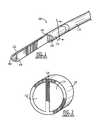
Figs. 3 and 4 , acatheter tip 200 according to an exemplary embodiment of the invention comprises anelongated shell 202 including afirst lumen 204 which, in the normal mode of operation, aspirates fluid from the vascular system (i.e., an inflow lumen) via afirst orifice 214 and asecond lumen 206 which, in the normal mode of operation, returns fluid from thecatheter tip 200 to the vascular system (i.e., an outflow lumen) via asecond orifice 216. Thelumens partition 212 extending substantially the length of thetip 200. As thetip 200 is substantially circular, thepartition 212 divides thetip 200 to form thelumens partition 212 may be altered as needed. Theshell 202 extends around thetip 200 on one side of thepartition 212 to thesecond orifice 216 and to thefirst orifice 214 on the other side of thepartition 212. As would be understood by those skilled in the art, thetip 200 may be integrally formed as part of a catheter, or may be manufactured separately and then attached to a catheter via any of a variety of conventional attachment methods. It will also be understood that, if desired, thetip 200 may include more than two lumens. - As seen in
Fig. 3 , the first andsecond orifices tip 200 are offset from one another along a longitudinal axis of thetip 200 and each of the first andsecond orifices Fig. 4 , aprotrusion 210 which, in this embodiment is a substantially cylindrical extrusion with a diameter smaller than an inner diameter of theshell 202 forms a rod extending substantially along a centerline of thepartition 212, coaxially with theshell 202. Theprotrusion 210 extends along substantially the entire length of theshell 202 above thepartition 212 in thedistal portion 220 of thetip 200, beyond thefirst orifice 214. In this embodiment, theprotrusion 210 is concentric with theshell 202. However, in other embodiments, theprotrusion 210 may not be concentric. In addition, the shape of theprotrusion 210 need not be circular and in other embodiments, the shape (e.g., triangular, elliptical, etc.) and/or the diameter of theprotrusion 210 may be adjusted to suit a particular need (e.g., a desired flow characteristic, flexibility, etc.). - According to the invention, the
protrusion 210 comprises a divertingstructure 208 which, in this embodiment is formed as a shallow cut positioned approximately half the distance along the longitudinal axis of thetip 200 between thefirst orifice 214 and thesecond orifice 216. However, those skilled in the art will understand that the divertingstructure 208 may be formed anywhere between the first andsecond orifices structure 208 may be sculpted by, for example, skiving a portion of theprotrusion 210 to form a downward sloping divertingstructure 222 and an upward sloping divertingstructure 224. Alternatively, the divertingstructure 208 may be formed by cutting theprotrusion 210 along a substantially constant radius. In the reverse mode of operation theprotrusion 210 and the divertingstructure 208 direct outflow from theoutlet orifice 214 upward, away from the longitudinal axis of thetip 200 and theinlet orifice 216. Additional embodiments may include multiple angled cuts formed by a series of skives, compound cuts, or any other method known to those skilled in the art. One or more of the multiple cuts may be angled about a radial axis of thetip 200 to bias flow to side of thetip 200 or to bias portions of the flows in different directions relative to an axis of thetip 200. Thus, the divertingstructure 208 may guide the flow laterally relative to the axis of thetip 200 in addition to diversion of the flow radially outward from the axis. - The
second orifice 216 is formed at an angle, extending proximally at an acute or, in the alternative, an obtuse, angle from a distal end of thepartition 212 which is preferably selected to provide desired flow characteristics to thetip 200. For example, a steeper angle may direct fluid further from the centerline in the reverse mode and draw fluid from further away in the normal mode. Those skilled in the art will understand that this angle may be formed by cutting thetip 200 along a desired plane, by molding, compound cutting, or by any other conventional method. - A computational fluid dynamics analysis of the flow generated by the exemplary tip described above in the reverse mode of operation is shown in
Fig. 5 . As shown inFig. 5 , in the reverse mode of operation, filteredblood 254 flows out of thelumen 204 to exit thetip 200 via thefirst orifice 214, initially passing over theprotrusion 210. However as the flow passes the divertingstructure 208, it is pushed away from the centerline of thetip 200 and away from thesecond orifice 216 as indicated by the transition from section 256 (dark shade of gray) to section 258 (light shade of gray), reducing recirculation. In addition, if radially angled cuts are included in theprotrusion 210, the flow is biased to one side (e.g., into the plane of the side view ofFig. 5 ). As shown in the diagram,unfiltered blood 250 is aspired into thesecond orifice 216, together with a reduced portion of the filteredblood 254. In the exemplary embodiment, the numerical modeling predicts a recirculation rate of about 15% for the conditions shown inFig. 5 . Figs. 6 and 7 show acatheter tip 300 according to an exemplary embodiment of the invention. Thetip 300 comprises anelongated shell 302 including afirst lumen 304 which, in the normal mode of operation, aspirates fluid from the vascular system (i.e., an inflow lumen) via afirst orifice 314 and asecond lumen 306 which, in the normal mode of operation, returns fluid from thetip 300 to the vascular system (i.e., an outflow lumen) via asecond orifice 316. Thelumens partition 312 extending substantially the length of thetip 300. Thepartition 312 divides thetip 300 to form thelumens partition 312 may be altered as needed. Theshell 302 extends around thetip 300 on one side of thepartition 312 to thesecond orifice 316 and to thefirst orifice 314 on the other side of thepartition 312. As would be understood by those skilled in the art, thetip 300 may be integrally formed as part of a catheter, or may be manufactured separately and then attached to a catheter via any of a variety of conventional attachment methods. It will also be understood that thetip 300 may include any plurality of lumens.- As seen in
Fig. 6 , the first andsecond orifices tip 300 are offset from one another along a longitudinal axis of thetip 300. As best seen in the cross-section ofFig. 7 , aprotrusion 310 which, in this embodiment is a substantially semi-circular extrusion with a cropped top surface and a diameter smaller than an inner diameter of theshell 302, forming a semi-circular rod extending substantially along a centerline of thepartition 312, coaxially with theshell 302. Theprotrusion 310 extends along substantially the entire length of theshell 302 above thepartition 312 in thedistal portion 320 of thetip 300, beyond thefirst orifice 314. Theprotrusion 310 reduces a cross-sectional size of thelumen 304 and imparts an arch shape thereto while not protruding into thelumen 312 at all. In this embodiment, theprotrusion 310 is concentric with theshell 302. However, in other embodiments, theprotrusion 310 may not be concentric. In addition, the shape of theprotrusion 310 need not be semi-circular and in other embodiments, the shape (e.g., triangular, elliptical, etc.) and/or the radius of theprotrusion 310 may be adjusted to suit a particular need (e.g., a desired flow characteristic). The amount of cropping may also be varied to produce a specific height profile for theprotrusion 310. - According to the invention, the
protrusion 310 comprises a divertingstructure 308 which, in this embodiment is formed as a shallow cut approximately half the distance along the longitudinal axis of thetip 300 between thefirst orifice 314 and thesecond orifice 316. The divertingstructure 308 may be sculpted in a manner similar to that of the divertingstructure 208. For example, a downward and/or an upward sloping diverting structure may be formed by skiving, cutting, etc. Additional embodiments may include multiple angled cuts formed by a series of skives, compound cuts, or any other method known to those skilled in the art. One or more of the multiple cuts may be angled about a radial axis of thetip 300 and function to bias flow to one or more sides of thetip 300. Thus, the divertingstructure 308 may guide the flow sideways in addition to upwards. - The
shell 302 may be sculpted (e.g., skived, cut, etc.) to include a pair ofside walls 318 extending between thefirst orifice 314 and thesecond orifice 316. Thewalls 318 may be formed by one or more lengthwise cuts across the tip of the device and may be driven by cross section geometry. As shown in the cross-section ofFig. 7 , thewalls 318 are angled in an upwardly radial direction. In the exemplary embodiment shown, an inner surface of thewalls 318 is curved to match the curvature of an inner surface of theshell 302. However, in other embodiments, the inner surface may be have a different shape, such as a bevel, a rounded edge, etc. that functions to guide the flow upwards, away from the centerline of thetip 300. A height of thewalls 318 may be selected to provide a desired flow characteristic. In the exemplary embodiment, the height of thewalls 318 is greater than the height of theprotrusion 310. However, if a greater amount of fluid diversion is desired, the height of thewalls 318 may be increased. - The
second orifice 316 is formed at an angle, extending proximally at an acute angle from a distal end of thepartition 312. The angle of thesecond orifice 316 may be selected to provide a desired flow characteristic. For example, a steeper angle may direct fluid further away from the centerline in the reverse mode and draw fluid from further away in the normal mode. Those skilled in the art will understand that this angle may be formed by cutting thetip 300 along a desired plane, by molding, compound cutting, or by any other suitable method. - A computational fluid dynamics analysis of the flow generated by the exemplary tip described above in the reverse mode of operation is shown in
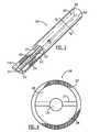
Fig. 8 . As shown inFig. 8 , in the reverse mode of operation, filteredblood 354 flows out of thelumen 304 to exit thetip 300 via thefirst orifice 314, initially passing over theprotrusion 310. However as the flow passes the divertingstructure 308, it is pushed away from the centerline of thetip 300 and away from thesecond orifice 316 as indicated by the transition from section 356 (dark gray) to section 358 (light gray), reducing recirculation. The flow is further directed by thewalls 318, the curvature of which guides the flow upwards. In addition, if radially angled cuts are included in theprotrusion 310, the flow is biased to one side (e.g., into the plane of the side view ofFig. 8 ). As shown in the diagram,unfiltered blood 350 is aspired into thesecond orifice 316, together with a reduced portion of the filteredblood 354. In the exemplary embodiment, the numerical modeling predicts a recirculation rate of about less than 20% in comparison to one another for the conditions shown inFig. 8 . Figs. 9 and 10 show acatheter tip 400 according to an exemplary embodiment of the invention. Thetip 400 comprises anelongated shell 402 including afirst lumen 404 which, in the normal mode of operation, aspirates fluid from the vascular system (i.e., an inflow lumen) via afirst orifice 414 and asecond lumen 406 which, in the normal mode of operation, returns fluid from thetip 400 to the vascular system (i.e., an outflow lumen) via asecond orifice 416. Thelumens partition 412 extending substantially the length of thetip 400. Acentral portion 422 of thepartition 412 is substantially cylindrical and divides thetip 400 to form cross-sections of thelumens central portion 422 comprises a substantially semi-circularthird lumen 408 which, in the normal mode of operation, aspirates fluid via athird orifice 418. As shown inFig. 9 , thethird orifice 418 is a radial opening located proximally from a distal end of thetip 400, between thefirst orifice 314 and thesecond orifice 316. Thethird orifice 418 may be formed by, for example, skiving or cutting into the upper half of thecentral portion 422 until thethird lumen 408 is exposed.Lumen 408 may be coupled withlumen 404. A distal wall of thethird orifice 418 is angled perpendicularly to a distal end of the upper half of thecentral portion 422. Thus, distal flow through thelumen 408 is abruptly diverted away from a centerline of thetip 400. However, if a less abrupt angle is desired, the distal wall of thethird orifice 418 may be shaped at an acute angle to the distal end of the upper half of thecentral portion 422.- Those skilled in the art will understand that if lumens of different size and shape are desired, the placement and/or the shape of the
partition 412 may be altered as needed. For example, in another embodiment, thepartition 412 may be shaped so as to form first and second lumens of different sizes. Theshell 402 extends around thetip 400 on one side of thepartition 412 to thesecond orifice 416 and to thefirst orifice 414 on the other side of thepartition 412. As would be understood by those skilled in the art, thetip 400 may be integrally formed as part of a catheter, or may be manufactured separately and then attached to a catheter via a conventional attachment method. - As seen in
Fig. 9 , the first andsecond orifices tip 400 are offset from one another along a longitudinal axis of thetip 400. As best seen in the cross-section ofFig. 10 , thethird lumen 408 extends along a centerline of thepartition 412, substantially along the entire length of theshell 402. It will be understood by those skilled in the art that the shape and/or position of thethird lumen 408 may be altered in other embodiments. For example, in one embodiment, thethird lumen 408 may be substantially circular and concentric with theshell 402. In other embodiments, thetip 400 may not be limited to three lumens. For example, a lower portion of thepartition 412 may comprise a fourth lumen which, in the normal mode, may function as an outflow or inflow lumen. - The
second orifice 416, along with a lower half of a distal end of thecentral portion 422, are formed at an angle, extending proximally at an acute angle from the distal end of the upper half of thecentral portion 422. The angles of thesecond orifice 416 and the lower half of thecentral portion 422 may be selected to provide a desired flow characteristic. For example, a steeper angle may direct fluid further away from the centerline in the reverse mode and draw fluid from further away in the normal mode. Those skilled in the art will understand that the angles may be formed by cutting thetip 400 along a desired plane, by molding, compound cutting, or by any other suitable method. As seen inFig. 9 , the angle of thesecond orifice 416 and the angle of the lower half are the same. However, in other embodiments, the angles may not match and may be formed by, for example, a series of cuts oriented at different angles. - A computational fluid dynamics analysis of the flow generated by the exemplary tip described above in the reverse mode of operation is shown in
Fig. 11 . As shown inFig. 11 , in the reverse mode of operation, filteredblood 454 flows simultaneously out of thelumens lumen 404 is radially dispersed upon reaching thefirst orifice 414. A remainder of the flow travels through thelumen 408 until reaching a distal wall thereof and being forced upward, away from the centerline of thetip 400. The upward flow is mixed with a portion of the radially dispersed flow, which has traveled distally to reach thethird orifice 418. The combined flow has a net upwards direction of travel, away from the centerline of thetip 400. As shown in the diagram,unfiltered blood 450 is aspired into thesecond orifice 416, together with a reduced portion of the filteredblood 454. In the exemplary embodiment, the numerical modeling predicts a recirculation rate of about less than 15% for the conditions shown inFig. 11 . - As shown in
Figs. 12 and 13 , acatheter tip 500 according to an exemplary embodiment comprises anelongated shell 502 including afirst lumen 504 which, in the normal mode of operation, aspirates fluid from the vascular system (i.e., an inflow lumen) via afirst orifice 514 and asecond lumen 506 which, in the normal mode of operation, returns fluid from thecatheter tip 500 to the vascular system (i.e., an outflow lumen) via asecond orifice 516. Thelumens partition 512 extending substantially the length of thetip 500. As thetip 500 is substantially circular, thepartition 512 divides thetip 500 substantially along the centerline of thetip 500 to form thelumens partition 512 may be altered as needed. Theshell 502 extends around thetip 500 on one side of thepartition 512 to thesecond orifice 516 and to thefirst orifice 514 on the other side of thepartition 512. As would be understood by those skilled in the art, thetip 500 may be integrally formed as part of a catheter, or may be manufactured separately and then attached to a catheter via any of a variety of conventional attachment methods. It will also be understood that thetip 500 may more than two lumens. - As seen in
Fig. 12 , the first andsecond orifices distal end 510 of thetip 500 on opposite sides of thepartition 512. Eachorifice distal end 510 and may be formed by skiving, compound cutting, or any other method known to those skilled in the art. The angles contribute to an offset distance between thedistal end 510 and a proximal end of theorifices orifices orifices 514, 516 (e.g., skiving, cutting, etc.). In addition, theorifices orifices distal end 510 to a proximal end of the orifice. According to this embodiment, each of theorifices partition 512. However, the angles may be any acute angle and may be different from one another. The angles are preferably in the range between 85° and 10°. However, those skilled in the art will recognize that the angles selected within this range on various desired design features of the catheter. - The
orifices partition 512. However, in other embodiments theorifices orifices lumens orifice 516 provides a large surface area from which to draw fluid proximally into thelumen 506. In addition, the angle of thesecond orifice 516 functions to draw fluid separated from thetip 500 in a direction oriented radially away from the centerline of thetip 500. Thefirst orifice 514 functions in a manner similar to that of thesecond orifice 216 in the normal and reverse modes. These embodiments may feature side skiving to bias the flow laterally away from the centerline of thetip 500. - A computational fluid dynamics analysis of the flow generated by the
tip 500 in the reverse mode of operation is shown inFig. 14 . As shown inFig. 14 , in the reverse mode of operation, filteredblood 554 flows out of thelumen 504 to exit thetip 500 via thefirst orifice 514 whileunfiltered blood 550 is aspired into thesecond orifice 516. When theblood 554 reaches the proximal end of theorifice 514, the angle of theorifice 514 disperses the blood radially away from the centerline of thetip 500 while also directing the flow distally away from thedistal end 510 of thetip 500. Thus, a majority of theblood 554 is directed away from the centerline of thetip 500 before reaching thedistal end 510. Because thesecond orifice 516 is located on the opposite side of thepartition 512, an amount of filteredblood 554 drawn therethrough into thelumen 506 is reduced. In the exemplary embodiment, the numerical modeling predicts a recirculation rate of about 5% for the conditions shown inFig. 13 . The symmetry of thetip 500 enables a similar recirculation rate in the normal mode of operation. That is, the recirculation rate of blood aspired into thefirst orifice 514 in the normal mode of operation is also approximately 5%. - As shown in
Figs. 15 and 16 , acatheter tip 600 according to a further exemplary embodiment comprises anelongated shell 602 including afirst lumen 604 which, in the normal mode of operation, aspirates fluid from the vascular system (i.e., an inflow lumen) via afirst orifice 614 and asecond lumen 606 which, in the normal mode of operation, returns fluid from thetip 600 to the vascular system (i.e., an outflow lumen) via asecond orifice 616. Thelumens partition 612 extending substantially the length of thetip 600. Thepartition 612 divides thetip 600 to form thelumens partition 612 may be altered as needed. Theshell 602 extends around thetip 600 on one side of thepartition 612 to thesecond orifice 616 and to thefirst orifice 614 on the other side of thepartition 612. As would be understood by those skilled in the art, thetip 600 may be integrally formed as part of a catheter, or may be manufactured separately and then attached to a catheter via any of a variety of conventional attachment methods. It will also be understood that thetip 600 may include more than two lumens. - The first and
second orifices tip 600 are substantially similar to the first andsecond orifices tip 500, located adjacent to one another on opposite sides of thepartition 612, and extend proximally from thedistal end 610 at acute angles (e.g., 30 degrees from a longitudinal axis of the tip 600) relative to thepartition 612. Those skilled in the art will understand that the angle of theorifices partition 612 may vary in the same range described above for theorifices - As seen in
Fig. 15 , thetip 600 includes athird orifice 624 and afourth orifice 626, which are respectively and fluidly coupled to thelumens fourth orifices fourth orifices distal end 610. Those skilled in the art will understand that the various distances between the first and second and third andfourth orifices Fig. 16 , the third andfourth orifices shell 602 and intersecting at a line separated from thepartition 612 by a distance selected to leave a portion of theshell 602 extending around a portion of thelumens walls partition 612 by a height which will vary depending on the desired design characteristics and expected use of the catheter. Theorifices shell 602 to form proximal anddistal walls distal walls walls partition 612. As described above in regard to the other embodiments of the invention, theorifices curved walls wall 618 and thepartition 612 and that formed between thewall 620 and thepartition 612 are preferably greater than the angle between theorifice 614 and thepartition 612 so that theorifice 614 has a larger opening than theorifice 624. The size and shape of 624 and 626 are preferably chosen to allow the drawing of blood from the most proximal orifice while the momentum of the returning blood carries the bulk of the flow past 624 (or 626) to the tip. - A computational fluid dynamics analysis of the flow generated by the
tip 600 in the reverse mode of operation is shown inFig. 17 . As shown inFig. 17 , in the reverse mode of operation, filteredblood 654 flows out of thelumen 604 to exit thetip 600 via thethird orifice 624. A remaining portion of the filteredblood 654 travels distally through thefirst lumen 604 to exit via thefirst orifice 614.Blood 654 exiting the first andthird orifices tip 600 while flowing distally away from theorifices second orifice 616 and thefourth orifice 626, together with a reduced portion of the filteredblood 654. Thefourth orifice 626 is closer to a pulling force of thesecond lumen 606 and thus, receives a majority of the blood drawn into thesecond lumen 606. Furthermore, because thefourth orifice 626 is located on the opposite side of thepartition 612 from thethird orifice 624 and is located proximally of thedistal end 610, the blood drawn therein is almost entirely comprised of unfiltered blood 650. Likewise, a majority of the filteredblood 654 exits via thethird orifice 624 while a small portion of the filteredblood 654 mixes with the unfiltered blood 650 at thedistal end 610. In the exemplary embodiment, the numerical modeling predicts a recirculation rate of about 3% for the conditions shown inFig. 17 . - As shown in
Fig. 18 and 19 , the orifices 614', 616' of a tip 600' oriented at angles of approximately 80° relative to the partition 612' to shorten the tip 600'. A computational fluid dynamics analysis of the flow generated by the tip 600' described above in the reverse mode of operation is shown inFig. 19 . The tip 600' operates in a manner substantially similar to that of thetip 600, with filtered blood 654' flowing simultaneously out of the orifices 614', 624' and unfiltered blood 650' returning via the orifice 616'. In the exemplary embodiment, the numerical modeling predicts a recirculation rate of about 3% for the conditions shown inFig. 19 . It is believed that, although the performance of thetip 600 was measured as substantially the same as that of the tip 600', the differences in geometry may result in different performance in vivo. - The present invention has been described with reference to specific embodiments, and more specifically to a dialysis catheter with multiple lumens. However, other embodiments may be devised that are applicable to different catheters (e.g., PICC, tunneled central, angiography, ERCP and drainage catheters) without departing from the scope of the invention. Accordingly, various modifications and changes may be made to the embodiments, without departing from the scope of the present invention as set forth in the claims that follow. The specification and drawings are accordingly to be regarded in an illustrative rather than restrictive sense.
Aspects of the description, inter alia, are: - 1. A flow control tip for a catheter, comprising:
- a partition dividing the catheter into first and second lumens ;
- a first orifice fluidly connected to the first lumen and a second orifice fluidly connected to the second lumen, the first orifice being proximal to the second orifice;
- an elongate protrusion extending along a portion of the partition substantially along a centerline of the elongated body; and
- a deflecting surface extending at an angle relative to the protrusion to direct flow from the first orifice away from the centerline.
- 2. The flow control tip according to aspect 1, further comprising a substantially cylindrical outer shell defining an outer wall of the first and the second lumens.
- 3. The flow control tip according to aspect 1, wherein the deflecting surface is located approximately halfway between the first and the second orifices.
- 4. The flow control tip according to aspect 1, wherein the protrusion protrudes substantially equally in the first and the second lumens.
- 5. The flow control tip according to aspect 1, wherein the protrusion is substantially hemispherical in cross-section, a radius of the protrusion being smaller than a radius of the elongated body.
- 6. The flow control tip according to aspect 1, wherein the deflecting surface includes a first portion extending from an outermost extent of the protrusion toward the partition in a proximal to distal direction and a second portion extending away from the partition toward the outermost extent of the protrusion.
- 7. The flow control tip according to aspect 1, the protrusion comprising a third lumen includes a radial opening located between the first and the second orifices.
- 8. A method for forming a catheter tip, comprising:
- extruding a tip blank comprising a first opening fluidly connected to a first lumen and
- a second opening orifice fluidly connected to a second lumen formed in a distal end of the tip blank, the first opening being separated from the distal end along a longitudinal axis of the tip blank by a stagger distance;
- forming a protrusion substantially along a centerline of a partition separating the first and second lumens from one another;
- removing a first portion of an outer wall of the tip blank surrounding the first lumen along at least a portion of the tip blank distally of the first opening; and
- removing a portion of the protrusion to form a first flow deflecting surface angled away from the partition in a proximal to distal direction.
- 9. The method according to aspect 8, further comprising removing a second portion of the protrusion to form a second deflecting surface angled toward the partition in a proximal to distal direction, the second deflecting surface being located immediately proximal to the first deflecting surface.
- 10.The method according to aspect 8, wherein the deflecting surface is skived into the protrusion.
- 11. A tip for a catheter, comprising
an outer wall defining first and second lumens separated from one another by a partition,
a first opening at a distal end of the tip on a first side of the partition opening the first lumen to an exterior of the tip the outer wall at the first opening defining a first acute angle with the partition so that a proximal end of the first opening is located proximally of the distal end of the tip, arid
a second opening at the distal end of the tip on a second side of the partition opening the second lumen to the exterior of the tip, the outer wall at the second opening defining a second acute angle with the partition so that a proximal end of the second opening is located proximally of the distal end of the tip. - 12. The catheter tip according to aspect 11, wherein the first opening is formed in a plane extending at the first acute angle relative to the partition.
- 13.The catheter tip according to aspect 11, wherein the first opening is formed along a curve intersecting the partition at the first acute angle.
- 14. The catheter tip according to aspect 11, wherein the first acute angle is between 10° and 85°.
- 15. The catheter tip according to aspect 11, further comprising a third opening located proximally of the first opening on the first side of the partition opening the first lumen to an exterior of the tip.
- 16.The catheter tip according to aspect 15, further comprising a fourth opening located proximally of the second opening on the second side of the partition opening the second lumen to an exterior of the tip.
- 17.The catheter tip according to aspect 15, wherein a periphery of a proximal portion of the third opening extends substantially in a plane extending distally from a proximal end of the third opening toward the partition at a third acute angle.
- 18.The catheter tip according to aspect 17, wherein a periphery of a distal portion of the third opening extends substantially in a plane extending proximally from a distal end of the third opening toward the partition at a fourth acute angle.
- 19.The catheter tip according to aspect 18, wherein the proximal and distal portions of the third opening meet at points on opposite sides of a longitudinal axis of the tip separated from the partition by a predetermined distance.
- 20. The catheter tip according to aspect 18, wherein the third acute angle is between 10° and 85° and the fourth acute angle is between between 10° and 85°.
- 21.The catheter tip according to aspect 18, wherein the third and fourth acute angles are substantially equal to one another.
- 22.The catheter tip according to aspect 16, wherein a periphery of a proximal portion of the fourth opening extends substantially in a plane extending distally from a proximal end of the fourth opening toward the partition at a fifth acute angle.
- 23.The catheter tip according to aspect 22, wherein a periphery of a distal portion of the fourth opening extends substantially in a plane extending proximally from a distal end of the fourth opening toward the partition at a sixth acute angle.
- 24.The catheter tip according to aspect 23, wherein the proximal and distal portions of the fourth opening meet at points on opposite sides of a longitudinal axis of the tip separated from the partition by a predetermined distance.
- 25.A method for making a catheter tip, comprising:
- skiving a tubular body including first and second lumens separated from one another by a partition along a first acute angle extending proximally from a distal tip of the catheter tip to form a first opening opening the first lumen to an exterior of the catheter tip; and
- skiving the tubular body along a second acute angle extending proximally from a distal tip of the catheter tip to form a second opening opening the second lumen to an exterior of the catheter tip.
Claims (15)
- A flow control tip (200, 300, 400) for a catheter, comprising:a partition (212, 312, 412) dividing the catheter into first and second lumens (204, 304, 404; 206, 306, 406) defined by an elongated body (202, 302, 402);a first orifice (214, 314, 414) fluidly connected to the first lumen and a second orifice (216, 316, 416) fluidly connected to the second lumen, the first orifice being proximal to thesecond orifice;characterized byan elongate protrusion (210, 310) extending substantially along the entire length of the partition substantially along a centerline of the elongated body; anda deflecting surface (208, 308) extending at an angle relative to the protrusion to direct flow from the first orifice away from the centerline.
- The flow control tip according to claim 1, further comprising a substantially cylindrical outer shell defining an outer wall of the first and the second lumens.
- The flow control tip according to claim 1, wherein the deflecting surface is located approximately halfway between the first and the second orifices.
- The flow control tip according to claim 1, wherein the protrusion protrudes substantially equally in the first and the second lumens.
- The flow control tip according to claim 1, wherein the protrusion is substantially hemispherical in cross-section, a radius of the protrusion being smaller than a radius of the elongated body.
- The flow control tip according to claim 1, wherein the deflecting surface includes a first portion extending from an outermost extent of the protrusion toward the partition in a proximal to distal direction and a second portion extending away from the partition toward the outermost extent of the protrusion.
- The flow control tip according to claim 1, the protrusion comprising a third lumen (408) including a radial opening (418) located between the first and the second orifices.
- The flow control tip according to claim 1, wherein the deflection surface is sculpted from the protrusion.
- The flow control tip according to claim 1, the protrusion comprising a third lumen (408) extending through the first or second lumen.
- The flow control tip according to claim 1, wherein the first or second orifice is formed in a plane extending at a first acute angle relative to the partition or a curve intersecting the partition at the first acute angle.
- The flow control tip according to claim 1, wherein angled walls (318) extend between the first orifice and the second orifice.
- The flow control tip according to claim 14, wherein a height of the angled walls is greater than a height of the protrusion.
- A method for forming a catheter tip(200, 300, 400), comprising:extruding a tip blank comprising a first opening (214, 314, 414) fluidly connected to a first lumen (204, 304, 404) and a second opening orifice (216, 316,416) fluidly connected to a second lumen (206, 306, 406) formed in a distal end (220, 320, 422) of the tip blank, the first opening being separated from the distal end along a longitudinal axis of the tip blank by a stagger distance;forming a protrusion substantially along a centerline of a partition separating the first and second lumens from one another and substantially extending along the entire length of the catheter tip;removing a first portion of an outer wall of the tip blank surrounding the first lumen along at least a portion of the tip blank distally of the first opening; andremoving a portion of the protrusion to form a first flow deflecting surface (208, 308) angled away from the partition in a proximal to distal direction.
- The method according to claim 13, further comprising removing a second portion of the protrusion to form a second deflecting surface angled toward the partition in a proximal to distal direction, the second deflecting surface being located immediately proximal to the first deflecting surface.
- The method according to claim 13, wherein the deflecting surface is skived into the protrusion.
Applications Claiming Priority (3)
| Application Number | Priority Date | Filing Date | Title |
|---|---|---|---|
| US98134307P | 2007-10-19 | 2007-10-19 | |
| US98137107P | 2007-10-19 | 2007-10-19 | |
| PCT/US2008/080519WO2009052506A1 (en) | 2007-10-19 | 2008-10-20 | Recirculation minimizing catheter |
Publications (2)
| Publication Number | Publication Date |
|---|---|
| EP2209515A1 EP2209515A1 (en) | 2010-07-28 |
| EP2209515B1true EP2209515B1 (en) | 2013-09-18 |
Family
ID=40227481
Family Applications (1)
| Application Number | Title | Priority Date | Filing Date |
|---|---|---|---|
| EP08840004.9ANot-in-forceEP2209515B1 (en) | 2007-10-19 | 2008-10-20 | Recirculation minimizing catheter |
Country Status (3)
| Country | Link |
|---|---|
| US (1) | US8337451B2 (en) |
| EP (1) | EP2209515B1 (en) |
| WO (1) | WO2009052506A1 (en) |
Families Citing this family (44)
| Publication number | Priority date | Publication date | Assignee | Title |
|---|---|---|---|---|
| US7393339B2 (en) | 2003-02-21 | 2008-07-01 | C. R. Bard, Inc. | Multi-lumen catheter with separate distal tips |
| US20040243095A1 (en) | 2003-05-27 | 2004-12-02 | Shekhar Nimkar | Methods and apparatus for inserting multi-lumen spit-tip catheters into a blood vessel |
| US8992454B2 (en) | 2004-06-09 | 2015-03-31 | Bard Access Systems, Inc. | Splitable tip catheter with bioresorbable adhesive |
| EP3689274A1 (en) | 2007-02-05 | 2020-08-05 | Boston Scientific Limited | Thrombectomy system |
| US8292841B2 (en) | 2007-10-26 | 2012-10-23 | C. R. Bard, Inc. | Solid-body catheter including lateral distal openings |
| US8066660B2 (en) | 2007-10-26 | 2011-11-29 | C. R. Bard, Inc. | Split-tip catheter including lateral distal openings |
| US9579485B2 (en) | 2007-11-01 | 2017-02-28 | C. R. Bard, Inc. | Catheter assembly including a multi-lumen configuration |
| CN101918067B (en) | 2007-11-01 | 2013-04-10 | C·R·巴德股份有限公司 | Catheter assembly including three lumen tips |
| US8403911B2 (en) | 2008-04-22 | 2013-03-26 | Becton, Dickinson And Company | Systems and methods for improving catheter hole array efficiency |
| US9399112B2 (en) | 2008-04-22 | 2016-07-26 | Becton, Dickinson And Company | Catheter hole having an inclined trailing edge |
| US9364634B2 (en) | 2008-04-22 | 2016-06-14 | Becton, Dickinson And Company | Systems and methods for improving catheter hole array efficiency |
| US8496629B2 (en) | 2008-04-22 | 2013-07-30 | Becton, Dickinson And Company | Catheter hole having a flow breaking feature |
| US9510854B2 (en) | 2008-10-13 | 2016-12-06 | Boston Scientific Scimed, Inc. | Thrombectomy catheter with control box having pressure/vacuum valve for synchronous aspiration and fluid irrigation |
| ATE544487T1 (en)* | 2009-03-12 | 2012-02-15 | Joline Gmbh & Co Kg | DOUBLE LUMINAL CATHETER |
| US8523757B2 (en) | 2009-06-04 | 2013-09-03 | Cardiogard Medical Ltd. | Arterial device, system and method for removing embolic debris |
| WO2011011406A1 (en)* | 2009-07-20 | 2011-01-27 | Ams Research Corporation | Devices, systems, and methods for delivering fluid to tissue |
| JP5455492B2 (en)* | 2009-07-30 | 2014-03-26 | 日本コヴィディエン株式会社 | Stylet and catheter set |
| WO2012009187A1 (en)* | 2010-07-15 | 2012-01-19 | Becton, Dickinson And Company | A catheter hole having an inclined trailing edge |
| JP2012065861A (en) | 2010-09-24 | 2012-04-05 | Nihon Covidien Kk | Dialysis catheter |
| US10107022B2 (en) | 2011-06-07 | 2018-10-23 | Henniges Automotive Schlegel Canada, Inc. | Draft guard for window assembly having seals and integral fins |
| US20120311934A1 (en) | 2011-06-07 | 2012-12-13 | Steven Robert Abramson | Draft Guard |
| US9044573B2 (en) | 2011-08-11 | 2015-06-02 | Phase One Medical, Llc | Method and apparatus for the dialysis of blood |
| US8636682B2 (en)* | 2011-09-29 | 2014-01-28 | Covidien Lp | Catheter with articulable septum extension |
| US20130085477A1 (en)* | 2011-09-29 | 2013-04-04 | Tyco Healthcare Group Lp | Catheter with tapering surfaces |
| USD748252S1 (en) | 2013-02-08 | 2016-01-26 | C. R. Bard, Inc. | Multi-lumen catheter tip |
| EP3071284B1 (en)* | 2013-11-21 | 2019-08-14 | C.R. Bard, Inc. | Catheter assembly including a multi-lumen configuration |
| US9883877B2 (en) | 2014-05-19 | 2018-02-06 | Walk Vascular, Llc | Systems and methods for removal of blood and thrombotic material |
| WO2016011091A1 (en) | 2014-07-14 | 2016-01-21 | C. R. Bard, Inc. | Apparatuses, systems, and methods for inserting split tip catheters having enhanced stiffening and guiding features |
| EP3215211A4 (en) | 2014-11-07 | 2018-07-04 | C. R. Bard, Inc. | Connection system for tunneled catheters |
| US10561440B2 (en) | 2015-09-03 | 2020-02-18 | Vesatek, Llc | Systems and methods for manipulating medical devices |
| US20170215897A1 (en)* | 2016-01-28 | 2017-08-03 | Gyrus Acmi, Inc., D.B.A. Olympus Surgical Technologies America | Apparatus for Stone Fragments Removal |
| US10492805B2 (en) | 2016-04-06 | 2019-12-03 | Walk Vascular, Llc | Systems and methods for thrombolysis and delivery of an agent |
| US10610668B2 (en) | 2016-10-05 | 2020-04-07 | Becton, Dickinson And Company | Catheter with an asymmetric tip |
| US11896782B2 (en) | 2017-08-23 | 2024-02-13 | C. R. Bard, Inc. | Priming and tunneling system for a retrograde catheter assembly |
| USD905853S1 (en) | 2018-02-27 | 2020-12-22 | Medical Components, Inc. | Catheter tip |
| US11678905B2 (en) | 2018-07-19 | 2023-06-20 | Walk Vascular, Llc | Systems and methods for removal of blood and thrombotic material |
| KR102341692B1 (en)* | 2019-05-21 | 2021-12-21 | 성균관대학교산학협력단 | Catheter |
| US11684749B2 (en) | 2019-09-04 | 2023-06-27 | Medical Components, Inc. | Catheter with tapered self-introducing low-recirculation distal tip |
| CN111569228A (en)* | 2020-05-21 | 2020-08-25 | 吉林大学 | An oral and maxillofacial anti-extrusion drainage half-pipe with scale |
| USD984880S1 (en) | 2020-11-06 | 2023-05-02 | Medical Components, Inc. | Clamp with indicator |
| JPWO2022118714A1 (en)* | 2020-12-01 | 2022-06-09 | ||
| CN112691279A (en)* | 2021-01-08 | 2021-04-23 | 苏州林华医疗器械股份有限公司 | Catheter for abdominal cavity implantation type drug administration device |
| JP2024506374A (en) | 2021-02-15 | 2024-02-13 | ウォーク バスキュラー, エルエルシー | System and method for removing blood and thrombotic material |
| US12274458B2 (en) | 2021-02-15 | 2025-04-15 | Walk Vascular, Llc | Systems and methods for removal of blood and thrombotic material |
Family Cites Families (105)
| Publication number | Priority date | Publication date | Assignee | Title |
|---|---|---|---|---|
| US3094124A (en) | 1960-06-30 | 1963-06-18 | Davol Rubber Co | Arterial catheter |
| US3438375A (en) | 1966-03-18 | 1969-04-15 | Kendall & Co | Non-traumatic retention catheter |
| US3978157A (en) | 1974-02-16 | 1976-08-31 | Bayer Aktiengesellschaft | Thermoplastic compositions comprising aromatic polycarbonate urethanes |
| US4054139A (en) | 1975-11-20 | 1977-10-18 | Crossley Kent B | Oligodynamic catheter |
| US4142525A (en) | 1977-03-10 | 1979-03-06 | The Kendall Company | Syringe assembly |
| US4483688A (en) | 1980-09-22 | 1984-11-20 | Hiroshi Akiyama | Catheter |
| US4403983A (en) | 1981-11-06 | 1983-09-13 | Shiley Incorporated | Dual lumen subclavian cannula |
| US4468224A (en) | 1982-01-28 | 1984-08-28 | Advanced Cardiovascular Systems, Inc. | System and method for catheter placement in blood vessels of a human patient |
| US4469483A (en) | 1982-08-25 | 1984-09-04 | Baxter Travenol Laboratories, Inc. | Radiopaque catheter |
| US4603152A (en) | 1982-11-05 | 1986-07-29 | Baxter Travenol Laboratories, Inc. | Antimicrobial compositions |
| US4592920A (en) | 1983-05-20 | 1986-06-03 | Baxter Travenol Laboratories, Inc. | Method for the production of an antimicrobial catheter |
| US4569673A (en) | 1984-01-12 | 1986-02-11 | Battelle Development Corporation | Bacterial barrier for indwelling catheters and other medical devices |
| US4563180A (en) | 1984-06-29 | 1986-01-07 | Raychem Corporation | High flow catheter for injecting fluids |
| US4623327A (en) | 1985-02-12 | 1986-11-18 | Mahurkar Sakharam D | Method and apparatus for using dual-lumen catheters for extracorporeal treatment |
| US4769005A (en) | 1987-08-06 | 1988-09-06 | Robert Ginsburg | Selective catheter guide |
| US4902503A (en) | 1987-11-25 | 1990-02-20 | Unitika Ltd. | Antimicrobial latex composition |
| CA1330285C (en) | 1987-12-22 | 1994-06-21 | Geoffrey S. Martin | Triple lumen catheter |
| US5019096A (en) | 1988-02-11 | 1991-05-28 | Trustees Of Columbia University In The City Of New York | Infection-resistant compositions, medical devices and surfaces and methods for preparing and using same |
| US4944726A (en) | 1988-11-03 | 1990-07-31 | Applied Vascular Devices | Device for power injection of fluids |
| US5569182A (en)* | 1990-01-08 | 1996-10-29 | The Curators Of The University Of Missouri | Clot resistant multiple lumen catheter and method |
| US5405320A (en) | 1990-01-08 | 1995-04-11 | The Curators Of The University Of Missouri | Multiple lumen catheter for hemodialysis |
| US5374245A (en)* | 1990-01-10 | 1994-12-20 | Mahurkar; Sakharam D. | Reinforced multiple-lumen catheter and apparatus and method for making the same |
| US5059170A (en) | 1990-02-02 | 1991-10-22 | Mallinckrodt Medical, Inc. | Connection adapter for catheters |
| US5151231A (en) | 1990-03-19 | 1992-09-29 | Becton, Dickinson And Company | Method for making liquid crystalline tube having a point |
| US5125893A (en) | 1990-04-16 | 1992-06-30 | Dryden Gale E | Suction catheter with wall lumen for irrigation |
| CA2038605C (en) | 1990-06-15 | 2000-06-27 | Leonard Pinchuk | Crack-resistant polycarbonate urethane polymer prostheses and the like |
| US5229431A (en) | 1990-06-15 | 1993-07-20 | Corvita Corporation | Crack-resistant polycarbonate urethane polymer prostheses and the like |
| US5205834A (en) | 1990-09-04 | 1993-04-27 | Moorehead H Robert | Two-way outdwelling slit valving of medical liquid flow through a cannula and methods |
| US5662913A (en) | 1991-04-10 | 1997-09-02 | Capelli; Christopher C. | Antimicrobial compositions useful for medical applications |
| US5879499A (en) | 1996-06-17 | 1999-03-09 | Heartport, Inc. | Method of manufacture of a multi-lumen catheter |
| US5249598A (en) | 1992-08-03 | 1993-10-05 | Vernay Laboratories, Inc. | Bi-directional vent and overpressure relief valve |
| GB2270845B (en) | 1992-09-24 | 1996-07-10 | Smiths Ind Med Syst Inc | Suction catheter assemblies |
| US5405340A (en) | 1992-10-07 | 1995-04-11 | Abbott Laboratories | Threaded securing apparatus for flow connectors |
| US5300048A (en) | 1993-05-12 | 1994-04-05 | Sabin Corporation | Flexible, highly radiopaque plastic material catheter |
| DE4316920A1 (en) | 1993-05-20 | 1994-11-24 | Michael Dr Med Hartmann | Endotracheal tube |
| US5403291A (en) | 1993-08-02 | 1995-04-04 | Quinton Instrument Company | Catheter with elongated side holes |
| US5380276A (en) | 1994-02-28 | 1995-01-10 | The Kendall Company | Dual lumen catheter and method of use |
| FR2718969B1 (en) | 1994-04-21 | 1996-07-12 | Balt Extrusion | Safety device for catheter, against overpressure during injection of product. |
| US5542937A (en) | 1994-06-24 | 1996-08-06 | Target Therapeutics, Inc. | Multilumen extruded catheter |
| US5614136A (en) | 1995-03-02 | 1997-03-25 | Scimed Life Systems, Inc. | Process to form dimensionally variable tubular members for use in catheter procedures |
| WO1996033761A1 (en) | 1995-04-28 | 1996-10-31 | Medtronic, Inc. | Intraparenchymal infusion catheter system |
| US5575769A (en) | 1995-05-30 | 1996-11-19 | Vaillancourt; Vincent L. | Cannula for a slit septum and a lock arrangement therefore |
| US20060052757A1 (en) | 1996-06-04 | 2006-03-09 | Vance Products Incorporated, D/B/A Cook Urological Incorporated | Implantable medical device with analgesic or anesthetic |
| US20040068241A1 (en) | 1996-06-04 | 2004-04-08 | Fischer Frank J. | Implantable medical device |
| US5843161A (en) | 1996-06-26 | 1998-12-01 | Cordis Corporation | Endoprosthesis assembly for percutaneous deployment and method of deploying same |
| FR2754718B1 (en) | 1996-10-18 | 1998-11-13 | Synthelabo | EXTENDED FLEXIBLE BODY CATHETER |
| US6530951B1 (en) | 1996-10-24 | 2003-03-11 | Cook Incorporated | Silver implantable medical device |
| US6033393A (en) | 1996-12-31 | 2000-03-07 | Johnson & Johnson Medical, Inc. | Method and apparatus for overpressure protection of a catheter |
| US6723121B1 (en) | 1997-06-18 | 2004-04-20 | Scimed Life Systems, Inc. | Polycarbonate-polyurethane dispersions for thrombo-resistant coatings |
| US6217566B1 (en) | 1997-10-02 | 2001-04-17 | Target Therapeutics, Inc. | Peripheral vascular delivery catheter |
| JP2001522654A (en) | 1997-11-07 | 2001-11-20 | サルヴィアック・リミテッド | Biostable polycarbonate urethane products |
| US5928174A (en) | 1997-11-14 | 1999-07-27 | Acrymed | Wound dressing device |
| US6605751B1 (en) | 1997-11-14 | 2003-08-12 | Acrymed | Silver-containing compositions, devices and methods for making |
| US20020091362A1 (en) | 1998-01-06 | 2002-07-11 | Maginot Thomas J. | Medical procedure using catheter system having removability feature |
| AU2568099A (en) | 1998-01-30 | 1999-08-16 | Tyco Group S.A.R.L. | Multiple lumen catheter with an enlarged tip |
| JP4612186B2 (en) | 1998-02-24 | 2011-01-12 | ナビリスト メディカル, インコーポレイテッド | High flow dialysis catheter and related methods |
| US6028125A (en) | 1998-06-10 | 2000-02-22 | River Valley Endodontics, P.A. | Dental root canal filling, retrofilling, and perforation repair materials |
| EP0987042A3 (en) | 1998-09-15 | 2000-11-02 | Medtronic, Inc. | Design and method to fabricate PTCA balloon radiopaque marker band |
| US6227200B1 (en) | 1998-09-21 | 2001-05-08 | Ballard Medical Products | Respiratory suction catheter apparatus |
| US6200338B1 (en) | 1998-12-31 | 2001-03-13 | Ethicon, Inc. | Enhanced radiopacity of peripheral and central catheter tubing |
| US6315789B1 (en) | 1999-02-08 | 2001-11-13 | Andrew H. Cragg | Medical device anchoring system and method |
| US6409700B1 (en) | 1999-03-22 | 2002-06-25 | Cfd Research Corporation | Double lumen catheter |
| US6368658B1 (en) | 1999-04-19 | 2002-04-09 | Scimed Life Systems, Inc. | Coating medical devices using air suspension |
| US6442415B1 (en) | 1999-08-12 | 2002-08-27 | Magnetic Moments, L.L.C. | Contrast-enhanced coronary artery and coronary artery bypass graft imaging using an aortic root catheter injection with either magnetic resonance angiography or computed tomographic angiography |
| US6375637B1 (en) | 1999-08-27 | 2002-04-23 | Gore Enterprise Holdings, Inc. | Catheter balloon having a controlled failure mechanism |
| JP4400972B2 (en) | 1999-12-13 | 2010-01-20 | 株式会社ミヤゲン | Biodegradable drained circular knit garbage bag for kitchen sinks |
| US7179849B2 (en) | 1999-12-15 | 2007-02-20 | C. R. Bard, Inc. | Antimicrobial compositions containing colloids of oligodynamic metals |
| AU2001229351A1 (en) | 2000-01-25 | 2001-08-07 | Boston Scientific Limited | Manufacturing medical devices by vapor deposition |
| US6743253B2 (en) | 2000-02-29 | 2004-06-01 | Biomod Surfaces | Polyurethane-sealed biocompatible device and method for its preparation |
| EP1267984B1 (en) | 2000-03-21 | 2005-11-09 | Cook Incorporated | Introducer sheath |
| US6945969B1 (en) | 2000-03-31 | 2005-09-20 | Medtronic, Inc. | Catheter for target specific drug delivery |
| JP4567847B2 (en) | 2000-05-30 | 2010-10-20 | ユニチカ株式会社 | Double lumen catheter |
| US6446671B2 (en) | 2000-08-04 | 2002-09-10 | John G. Armenia | Double wall safety hose |
| US6545097B2 (en) | 2000-12-12 | 2003-04-08 | Scimed Life Systems, Inc. | Drug delivery compositions and medical devices containing block copolymer |
| US6517520B2 (en) | 2000-12-21 | 2003-02-11 | Ethicon Endo Surgery, Inc. | Peripherally inserted catheter with flushable guide-tube |
| JP3730888B2 (en) | 2001-07-26 | 2006-01-05 | 日本電気通信システム株式会社 | E-mail access system and e-mail access method |
| US6629969B2 (en) | 2001-07-26 | 2003-10-07 | Durect Corporation | Catheter for modification of agent formulation |
| US6663596B2 (en) | 2001-08-13 | 2003-12-16 | Scimed Life Systems, Inc. | Delivering material to a patient |
| CA2457189C (en) | 2001-09-28 | 2011-08-09 | Boston Scientific Limited | Medical devices comprising nanomaterials and therapeutic methods utilizing the same |
| US6777466B2 (en) | 2002-02-08 | 2004-08-17 | Noveon Ip Holdings Corp. | Flame retardant thermoplastic polyurethane containing melamine cyanurate |
| WO2003077866A2 (en) | 2002-03-14 | 2003-09-25 | Ash Access Technology, Inc. | Medical devices exhibiting antibacterial properties |
| US7008979B2 (en) | 2002-04-30 | 2006-03-07 | Hydromer, Inc. | Coating composition for multiple hydrophilic applications |
| DE20208420U1 (en) | 2002-05-25 | 2002-10-31 | Diez, Claudius, 06114 Halle | Pressure relief cylinder for vascular surgery |
| US20040076582A1 (en) | 2002-08-30 | 2004-04-22 | Dimatteo Kristian | Agent delivery particle |
| US6819951B2 (en) | 2002-09-24 | 2004-11-16 | Mayo Foundation For Medical Education And Research | Peripherally inserted central catheter with continuous central venous oximetry and proximal high flow port |
| US6638301B1 (en) | 2002-10-02 | 2003-10-28 | Scimed Life Systems, Inc. | Medical device with radiopacity |
| US20040073171A1 (en) | 2002-10-10 | 2004-04-15 | Rogers Bobby E. | Needle-free valve and catheter assembly |
| JP4960631B2 (en) | 2002-10-11 | 2012-06-27 | ユニバーシティ オブ コネチカット | Shape memory polymers based on semi-crystalline thermoplastic polyurethane with nanostructured hard segments |
| US7794494B2 (en) | 2002-10-11 | 2010-09-14 | Boston Scientific Scimed, Inc. | Implantable medical devices |
| US7264858B2 (en) | 2002-10-29 | 2007-09-04 | Lubrizol Advanced Materials, Inc. | Multilayered articles having biocompatibility and biostability characteristics |
| US7776005B2 (en)* | 2003-03-28 | 2010-08-17 | Covidien Ag | Triple lumen catheter with occlusion resistant tip |
| US20050013988A1 (en) | 2003-04-16 | 2005-01-20 | Qiang Fu | Stimuli responsive mesoporous materials for control of molecular transport |
| US20040220534A1 (en) | 2003-04-29 | 2004-11-04 | Martens Paul W. | Medical device with antimicrobial layer |
| US8148475B2 (en) | 2003-06-30 | 2012-04-03 | Lubrizol Advanced Materials, Inc. | Melt spun polyether TPU fibers having mixed polyols and process |
| WO2005018712A2 (en)* | 2003-08-20 | 2005-03-03 | Datascope Investment Corp. | Dialysis catheter with stiffner |
| US20050182352A1 (en) | 2004-02-12 | 2005-08-18 | Dimatteo Kristian | Dialysis catheter tip |
| US8323227B2 (en)* | 2004-07-02 | 2012-12-04 | C. R. Bard, Inc. | Tip configurations for a multi-lumen catheter |
| JP2006296694A (en) | 2005-04-20 | 2006-11-02 | Japan Atomic Energy Agency | Decomposition method of halogenated organic compound |
| US20070299043A1 (en) | 2005-10-03 | 2007-12-27 | Hunter William L | Anti-scarring drug combinations and use thereof |
| WO2007056762A2 (en) | 2005-11-09 | 2007-05-18 | C.R. Bard Inc. | Grafts and stent grafts having a radiopaque beading |
| US8317773B2 (en)* | 2006-11-07 | 2012-11-27 | Angio Dynamics, Inc. | Catheter with open faced sloped end portion |
| US20090036768A1 (en) | 2006-11-17 | 2009-02-05 | Boston Scientific Scimed, Inc. | Medical devices |
| WO2008115543A2 (en) | 2007-03-20 | 2008-09-25 | Boston Scientific Scimed, Inc. | Urological medical devices for release of therapeutic agents |
| US8647323B2 (en) | 2007-12-30 | 2014-02-11 | St. Jude Medical, Atrial Fibrillation Division, Inc. | Catheter shaft with multiple reinforcing layers and method of its manufacture |
| US9962523B2 (en) | 2008-06-27 | 2018-05-08 | Merit Medical Systems, Inc. | Catheter with radiopaque marker |
- 2008
- 2008-10-20WOPCT/US2008/080519patent/WO2009052506A1/enactiveApplication Filing
- 2008-10-20USUS12/254,532patent/US8337451B2/ennot_activeExpired - Fee Related
- 2008-10-20EPEP08840004.9Apatent/EP2209515B1/ennot_activeNot-in-force
Also Published As
| Publication number | Publication date |
|---|---|
| US8337451B2 (en) | 2012-12-25 |
| WO2009052506A1 (en) | 2009-04-23 |
| EP2209515A1 (en) | 2010-07-28 |
| US20090187141A1 (en) | 2009-07-23 |
Similar Documents
| Publication | Publication Date | Title |
|---|---|---|
| EP2209515B1 (en) | Recirculation minimizing catheter | |
| US6808510B1 (en) | Multi-lumen catheter and tip configurations for use therewith | |
| JP2007521913A (en) | Dialysis catheter tip | |
| US20060100572A1 (en) | Dialysis catheter tip and method of manufacture | |
| EP1898990B1 (en) | Security tip for vascular catheter | |
| JP4456634B2 (en) | Triple lumen catheter with anti-obstruction tip | |
| EP1313527B1 (en) | Multi-lumen catheter and tip configurations for use therewith | |
| US8079990B2 (en) | Implantable catheter port | |
| EP2228090B1 (en) | Double lumen catheter | |
| JP2008503274A5 (en) | ||
| AU2001288475A1 (en) | Multi-lumen catheter and tip configurations for use therewith | |
| JP2022534978A (en) | flushing catheter | |
| US20110213291A1 (en) | Hemodialysis catheter | |
| WO2004093923A2 (en) | Aortic cannula | |
| US20140155802A1 (en) | Catheter | |
| HK1079468A1 (en) | Catheter with occlusion resistant tip |
Legal Events
| Date | Code | Title | Description |
|---|---|---|---|
| PUAI | Public reference made under article 153(3) epc to a published international application that has entered the european phase | Free format text:ORIGINAL CODE: 0009012 | |
| 17P | Request for examination filed | Effective date:20100419 | |
| AK | Designated contracting states | Kind code of ref document:A1 Designated state(s):AT BE BG CH CY CZ DE DK EE ES FI FR GB GR HR HU IE IS IT LI LT LU LV MC MT NL NO PL PT RO SE SI SK TR | |
| AX | Request for extension of the european patent | Extension state:AL BA MK RS | |
| DAX | Request for extension of the european patent (deleted) | ||
| GRAP | Despatch of communication of intention to grant a patent | Free format text:ORIGINAL CODE: EPIDOSNIGR1 | |
| INTG | Intention to grant announced | Effective date:20130327 | |
| GRAS | Grant fee paid | Free format text:ORIGINAL CODE: EPIDOSNIGR3 | |
| GRAA | (expected) grant | Free format text:ORIGINAL CODE: 0009210 | |
| AK | Designated contracting states | Kind code of ref document:B1 Designated state(s):AT BE BG CH CY CZ DE DK EE ES FI FR GB GR HR HU IE IS IT LI LT LU LV MC MT NL NO PL PT RO SE SI SK TR | |
| REG | Reference to a national code | Ref country code:GB Ref legal event code:FG4D | |
| REG | Reference to a national code | Ref country code:CH Ref legal event code:EP | |
| REG | Reference to a national code | Ref country code:IE Ref legal event code:FG4D | |
| REG | Reference to a national code | Ref country code:AT Ref legal event code:REF Ref document number:632402 Country of ref document:AT Kind code of ref document:T Effective date:20131015 | |
| REG | Reference to a national code | Ref country code:DE Ref legal event code:R096 Ref document number:602008027685 Country of ref document:DE Effective date:20131114 | |
| PG25 | Lapsed in a contracting state [announced via postgrant information from national office to epo] | Ref country code:CY Free format text:LAPSE BECAUSE OF FAILURE TO SUBMIT A TRANSLATION OF THE DESCRIPTION OR TO PAY THE FEE WITHIN THE PRESCRIBED TIME-LIMIT Effective date:20130904 Ref country code:NO Free format text:LAPSE BECAUSE OF FAILURE TO SUBMIT A TRANSLATION OF THE DESCRIPTION OR TO PAY THE FEE WITHIN THE PRESCRIBED TIME-LIMIT Effective date:20131218 Ref country code:HR Free format text:LAPSE BECAUSE OF FAILURE TO SUBMIT A TRANSLATION OF THE DESCRIPTION OR TO PAY THE FEE WITHIN THE PRESCRIBED TIME-LIMIT Effective date:20130918 Ref country code:SE Free format text:LAPSE BECAUSE OF FAILURE TO SUBMIT A TRANSLATION OF THE DESCRIPTION OR TO PAY THE FEE WITHIN THE PRESCRIBED TIME-LIMIT Effective date:20130918 Ref country code:LT Free format text:LAPSE BECAUSE OF FAILURE TO SUBMIT A TRANSLATION OF THE DESCRIPTION OR TO PAY THE FEE WITHIN THE PRESCRIBED TIME-LIMIT Effective date:20130918 | |
| REG | Reference to a national code | Ref country code:NL Ref legal event code:VDEP Effective date:20130918 | |
| REG | Reference to a national code | Ref country code:AT Ref legal event code:MK05 Ref document number:632402 Country of ref document:AT Kind code of ref document:T Effective date:20130918 | |
| REG | Reference to a national code | Ref country code:LT Ref legal event code:MG4D | |
| PG25 | Lapsed in a contracting state [announced via postgrant information from national office to epo] | Ref country code:GR Free format text:LAPSE BECAUSE OF FAILURE TO SUBMIT A TRANSLATION OF THE DESCRIPTION OR TO PAY THE FEE WITHIN THE PRESCRIBED TIME-LIMIT Effective date:20131219 Ref country code:ES Free format text:LAPSE BECAUSE OF FAILURE TO SUBMIT A TRANSLATION OF THE DESCRIPTION OR TO PAY THE FEE WITHIN THE PRESCRIBED TIME-LIMIT Effective date:20130918 Ref country code:FI Free format text:LAPSE BECAUSE OF FAILURE TO SUBMIT A TRANSLATION OF THE DESCRIPTION OR TO PAY THE FEE WITHIN THE PRESCRIBED TIME-LIMIT Effective date:20130918 Ref country code:SI Free format text:LAPSE BECAUSE OF FAILURE TO SUBMIT A TRANSLATION OF THE DESCRIPTION OR TO PAY THE FEE WITHIN THE PRESCRIBED TIME-LIMIT Effective date:20130918 Ref country code:LV Free format text:LAPSE BECAUSE OF FAILURE TO SUBMIT A TRANSLATION OF THE DESCRIPTION OR TO PAY THE FEE WITHIN THE PRESCRIBED TIME-LIMIT Effective date:20130918 | |
| PG25 | Lapsed in a contracting state [announced via postgrant information from national office to epo] | Ref country code:CY Free format text:LAPSE BECAUSE OF FAILURE TO SUBMIT A TRANSLATION OF THE DESCRIPTION OR TO PAY THE FEE WITHIN THE PRESCRIBED TIME-LIMIT Effective date:20130918 Ref country code:BE Free format text:LAPSE BECAUSE OF FAILURE TO SUBMIT A TRANSLATION OF THE DESCRIPTION OR TO PAY THE FEE WITHIN THE PRESCRIBED TIME-LIMIT Effective date:20130918 | |
| PG25 | Lapsed in a contracting state [announced via postgrant information from national office to epo] | Ref country code:IS Free format text:LAPSE BECAUSE OF FAILURE TO SUBMIT A TRANSLATION OF THE DESCRIPTION OR TO PAY THE FEE WITHIN THE PRESCRIBED TIME-LIMIT Effective date:20140118 Ref country code:NL Free format text:LAPSE BECAUSE OF FAILURE TO SUBMIT A TRANSLATION OF THE DESCRIPTION OR TO PAY THE FEE WITHIN THE PRESCRIBED TIME-LIMIT Effective date:20130918 Ref country code:CZ Free format text:LAPSE BECAUSE OF FAILURE TO SUBMIT A TRANSLATION OF THE DESCRIPTION OR TO PAY THE FEE WITHIN THE PRESCRIBED TIME-LIMIT Effective date:20130918 Ref country code:RO Free format text:LAPSE BECAUSE OF FAILURE TO SUBMIT A TRANSLATION OF THE DESCRIPTION OR TO PAY THE FEE WITHIN THE PRESCRIBED TIME-LIMIT Effective date:20130918 Ref country code:SK Free format text:LAPSE BECAUSE OF FAILURE TO SUBMIT A TRANSLATION OF THE DESCRIPTION OR TO PAY THE FEE WITHIN THE PRESCRIBED TIME-LIMIT Effective date:20130918 Ref country code:EE Free format text:LAPSE BECAUSE OF FAILURE TO SUBMIT A TRANSLATION OF THE DESCRIPTION OR TO PAY THE FEE WITHIN THE PRESCRIBED TIME-LIMIT Effective date:20130918 | |
| PG25 | Lapsed in a contracting state [announced via postgrant information from national office to epo] | Ref country code:AT Free format text:LAPSE BECAUSE OF FAILURE TO SUBMIT A TRANSLATION OF THE DESCRIPTION OR TO PAY THE FEE WITHIN THE PRESCRIBED TIME-LIMIT Effective date:20130918 Ref country code:PL Free format text:LAPSE BECAUSE OF FAILURE TO SUBMIT A TRANSLATION OF THE DESCRIPTION OR TO PAY THE FEE WITHIN THE PRESCRIBED TIME-LIMIT Effective date:20130918 | |
| REG | Reference to a national code | Ref country code:CH Ref legal event code:PL | |
| PG25 | Lapsed in a contracting state [announced via postgrant information from national office to epo] | Ref country code:MC Free format text:LAPSE BECAUSE OF FAILURE TO SUBMIT A TRANSLATION OF THE DESCRIPTION OR TO PAY THE FEE WITHIN THE PRESCRIBED TIME-LIMIT Effective date:20130918 Ref country code:PT Free format text:LAPSE BECAUSE OF FAILURE TO SUBMIT A TRANSLATION OF THE DESCRIPTION OR TO PAY THE FEE WITHIN THE PRESCRIBED TIME-LIMIT Effective date:20140120 | |
| PLBE | No opposition filed within time limit | Free format text:ORIGINAL CODE: 0009261 | |
| STAA | Information on the status of an ep patent application or granted ep patent | Free format text:STATUS: NO OPPOSITION FILED WITHIN TIME LIMIT | |
| REG | Reference to a national code | Ref country code:IE Ref legal event code:MM4A | |
| PG25 | Lapsed in a contracting state [announced via postgrant information from national office to epo] | Ref country code:CH Free format text:LAPSE BECAUSE OF NON-PAYMENT OF DUE FEES Effective date:20131031 Ref country code:LI Free format text:LAPSE BECAUSE OF NON-PAYMENT OF DUE FEES Effective date:20131031 | |
| REG | Reference to a national code | Ref country code:FR Ref legal event code:ST Effective date:20140630 | |
| REG | Reference to a national code | Ref country code:DE Ref legal event code:R119 Ref document number:602008027685 Country of ref document:DE Effective date:20140501 | |
| 26N | No opposition filed | Effective date:20140619 | |
| GBPC | Gb: european patent ceased through non-payment of renewal fee | Effective date:20131218 | |
| PG25 | Lapsed in a contracting state [announced via postgrant information from national office to epo] | Ref country code:DE Free format text:LAPSE BECAUSE OF NON-PAYMENT OF DUE FEES Effective date:20140501 Ref country code:FR Free format text:LAPSE BECAUSE OF NON-PAYMENT OF DUE FEES Effective date:20131118 Ref country code:IT Free format text:LAPSE BECAUSE OF FAILURE TO SUBMIT A TRANSLATION OF THE DESCRIPTION OR TO PAY THE FEE WITHIN THE PRESCRIBED TIME-LIMIT Effective date:20130918 | |
| PG25 | Lapsed in a contracting state [announced via postgrant information from national office to epo] | Ref country code:DK Free format text:LAPSE BECAUSE OF FAILURE TO SUBMIT A TRANSLATION OF THE DESCRIPTION OR TO PAY THE FEE WITHIN THE PRESCRIBED TIME-LIMIT Effective date:20130918 | |
| PG25 | Lapsed in a contracting state [announced via postgrant information from national office to epo] | Ref country code:IE Free format text:LAPSE BECAUSE OF NON-PAYMENT OF DUE FEES Effective date:20131020 | |
| PG25 | Lapsed in a contracting state [announced via postgrant information from national office to epo] | Ref country code:GB Free format text:LAPSE BECAUSE OF NON-PAYMENT OF DUE FEES Effective date:20131218 | |
| PG25 | Lapsed in a contracting state [announced via postgrant information from national office to epo] | Ref country code:TR Free format text:LAPSE BECAUSE OF FAILURE TO SUBMIT A TRANSLATION OF THE DESCRIPTION OR TO PAY THE FEE WITHIN THE PRESCRIBED TIME-LIMIT Effective date:20130918 | |
| PG25 | Lapsed in a contracting state [announced via postgrant information from national office to epo] | Ref country code:HU Free format text:LAPSE BECAUSE OF FAILURE TO SUBMIT A TRANSLATION OF THE DESCRIPTION OR TO PAY THE FEE WITHIN THE PRESCRIBED TIME-LIMIT; INVALID AB INITIO Effective date:20081020 Ref country code:LU Free format text:LAPSE BECAUSE OF NON-PAYMENT OF DUE FEES Effective date:20131020 Ref country code:BG Free format text:LAPSE BECAUSE OF FAILURE TO SUBMIT A TRANSLATION OF THE DESCRIPTION OR TO PAY THE FEE WITHIN THE PRESCRIBED TIME-LIMIT Effective date:20130918 | |
| PG25 | Lapsed in a contracting state [announced via postgrant information from national office to epo] | Ref country code:MT Free format text:LAPSE BECAUSE OF FAILURE TO SUBMIT A TRANSLATION OF THE DESCRIPTION OR TO PAY THE FEE WITHIN THE PRESCRIBED TIME-LIMIT Effective date:20130918 |