EP2209441B1 - Vertebral body replacement device - Google Patents
Vertebral body replacement deviceDownload PDFInfo
- Publication number
- EP2209441B1 EP2209441B1EP08844082.1AEP08844082AEP2209441B1EP 2209441 B1EP2209441 B1EP 2209441B1EP 08844082 AEP08844082 AEP 08844082AEP 2209441 B1EP2209441 B1EP 2209441B1
- Authority
- EP
- European Patent Office
- Prior art keywords
- replacement device
- wall
- vertebral body
- central rod
- body replacement
- Prior art date
- Legal status (The legal status is an assumption and is not a legal conclusion. Google has not performed a legal analysis and makes no representation as to the accuracy of the status listed.)
- Not-in-force
Links
- 230000033001locomotionEffects0.000claimsdescription16
- 239000000560biocompatible materialSubstances0.000claimsdescription4
- 238000000034methodMethods0.000description14
- 239000007943implantSubstances0.000description11
- 238000002513implantationMethods0.000description10
- 210000000988bone and boneAnatomy0.000description8
- 230000007246mechanismEffects0.000description5
- 238000001727in vivoMethods0.000description4
- 125000006850spacer groupChemical group0.000description4
- 230000006378damageEffects0.000description3
- 230000008878couplingEffects0.000description2
- 238000010168coupling processMethods0.000description2
- 238000005859coupling reactionMethods0.000description2
- 238000013461designMethods0.000description2
- 230000004927fusionEffects0.000description2
- 210000003734kidneyAnatomy0.000description2
- 239000000463materialSubstances0.000description2
- 230000007935neutral effectEffects0.000description2
- 230000008569processEffects0.000description2
- 238000004904shorteningMethods0.000description2
- 210000000278spinal cordAnatomy0.000description2
- 238000001356surgical procedureMethods0.000description2
- 208000012902Nervous system diseaseDiseases0.000description1
- 208000027418Wounds and injuryDiseases0.000description1
- 238000007792additionMethods0.000description1
- 230000002457bidirectional effectEffects0.000description1
- 230000006735deficitEffects0.000description1
- 230000001419dependent effectEffects0.000description1
- 238000011161developmentMethods0.000description1
- 230000018109developmental processEffects0.000description1
- 201000010099diseaseDiseases0.000description1
- 208000037265diseases, disorders, signs and symptomsDiseases0.000description1
- 238000002224dissectionMethods0.000description1
- 208000014674injuryDiseases0.000description1
- 238000003780insertionMethods0.000description1
- 230000037431insertionEffects0.000description1
- 230000007774longtermEffects0.000description1
- 230000001045lordotic effectEffects0.000description1
- 210000004705lumbosacral regionAnatomy0.000description1
- 230000013011matingEffects0.000description1
- 230000005012migrationEffects0.000description1
- 238000013508migrationMethods0.000description1
- 238000012986modificationMethods0.000description1
- 230000004048modificationEffects0.000description1
- 239000002105nanoparticleSubstances0.000description1
- 230000002093peripheral effectEffects0.000description1
- 238000003825pressingMethods0.000description1
- 238000004513sizingMethods0.000description1
- 210000000273spinal nerve rootAnatomy0.000description1
- 238000006467substitution reactionMethods0.000description1
- 210000000115thoracic cavityAnatomy0.000description1
Images


Classifications
- A—HUMAN NECESSITIES
- A61—MEDICAL OR VETERINARY SCIENCE; HYGIENE
- A61F—FILTERS IMPLANTABLE INTO BLOOD VESSELS; PROSTHESES; DEVICES PROVIDING PATENCY TO, OR PREVENTING COLLAPSING OF, TUBULAR STRUCTURES OF THE BODY, e.g. STENTS; ORTHOPAEDIC, NURSING OR CONTRACEPTIVE DEVICES; FOMENTATION; TREATMENT OR PROTECTION OF EYES OR EARS; BANDAGES, DRESSINGS OR ABSORBENT PADS; FIRST-AID KITS
- A61F2/00—Filters implantable into blood vessels; Prostheses, i.e. artificial substitutes or replacements for parts of the body; Appliances for connecting them with the body; Devices providing patency to, or preventing collapsing of, tubular structures of the body, e.g. stents
- A61F2/02—Prostheses implantable into the body
- A61F2/30—Joints
- A61F2/44—Joints for the spine, e.g. vertebrae, spinal discs
- A—HUMAN NECESSITIES
- A61—MEDICAL OR VETERINARY SCIENCE; HYGIENE
- A61F—FILTERS IMPLANTABLE INTO BLOOD VESSELS; PROSTHESES; DEVICES PROVIDING PATENCY TO, OR PREVENTING COLLAPSING OF, TUBULAR STRUCTURES OF THE BODY, e.g. STENTS; ORTHOPAEDIC, NURSING OR CONTRACEPTIVE DEVICES; FOMENTATION; TREATMENT OR PROTECTION OF EYES OR EARS; BANDAGES, DRESSINGS OR ABSORBENT PADS; FIRST-AID KITS
- A61F2/00—Filters implantable into blood vessels; Prostheses, i.e. artificial substitutes or replacements for parts of the body; Appliances for connecting them with the body; Devices providing patency to, or preventing collapsing of, tubular structures of the body, e.g. stents
- A61F2/02—Prostheses implantable into the body
- A61F2/30—Joints
- A61F2/46—Special tools for implanting artificial joints
- A61F2/4637—Special tools for implanting artificial joints for connecting or disconnecting two parts of a prosthesis
- A—HUMAN NECESSITIES
- A61—MEDICAL OR VETERINARY SCIENCE; HYGIENE
- A61F—FILTERS IMPLANTABLE INTO BLOOD VESSELS; PROSTHESES; DEVICES PROVIDING PATENCY TO, OR PREVENTING COLLAPSING OF, TUBULAR STRUCTURES OF THE BODY, e.g. STENTS; ORTHOPAEDIC, NURSING OR CONTRACEPTIVE DEVICES; FOMENTATION; TREATMENT OR PROTECTION OF EYES OR EARS; BANDAGES, DRESSINGS OR ABSORBENT PADS; FIRST-AID KITS
- A61F2/00—Filters implantable into blood vessels; Prostheses, i.e. artificial substitutes or replacements for parts of the body; Appliances for connecting them with the body; Devices providing patency to, or preventing collapsing of, tubular structures of the body, e.g. stents
- A61F2/02—Prostheses implantable into the body
- A61F2/30—Joints
- A61F2/30721—Accessories
- A61F2/30734—Modular inserts, sleeves or augments, e.g. placed on proximal part of stem for fixation purposes or wedges for bridging a bone defect
- A—HUMAN NECESSITIES
- A61—MEDICAL OR VETERINARY SCIENCE; HYGIENE
- A61F—FILTERS IMPLANTABLE INTO BLOOD VESSELS; PROSTHESES; DEVICES PROVIDING PATENCY TO, OR PREVENTING COLLAPSING OF, TUBULAR STRUCTURES OF THE BODY, e.g. STENTS; ORTHOPAEDIC, NURSING OR CONTRACEPTIVE DEVICES; FOMENTATION; TREATMENT OR PROTECTION OF EYES OR EARS; BANDAGES, DRESSINGS OR ABSORBENT PADS; FIRST-AID KITS
- A61F2/00—Filters implantable into blood vessels; Prostheses, i.e. artificial substitutes or replacements for parts of the body; Appliances for connecting them with the body; Devices providing patency to, or preventing collapsing of, tubular structures of the body, e.g. stents
- A61F2/02—Prostheses implantable into the body
- A61F2/30—Joints
- A61F2/30721—Accessories
- A61F2/30744—End caps, e.g. for closing an endoprosthetic cavity
- A—HUMAN NECESSITIES
- A61—MEDICAL OR VETERINARY SCIENCE; HYGIENE
- A61F—FILTERS IMPLANTABLE INTO BLOOD VESSELS; PROSTHESES; DEVICES PROVIDING PATENCY TO, OR PREVENTING COLLAPSING OF, TUBULAR STRUCTURES OF THE BODY, e.g. STENTS; ORTHOPAEDIC, NURSING OR CONTRACEPTIVE DEVICES; FOMENTATION; TREATMENT OR PROTECTION OF EYES OR EARS; BANDAGES, DRESSINGS OR ABSORBENT PADS; FIRST-AID KITS
- A61F2/00—Filters implantable into blood vessels; Prostheses, i.e. artificial substitutes or replacements for parts of the body; Appliances for connecting them with the body; Devices providing patency to, or preventing collapsing of, tubular structures of the body, e.g. stents
- A61F2/02—Prostheses implantable into the body
- A61F2/28—Bones
- A61F2002/2835—Bone graft implants for filling a bony defect or an endoprosthesis cavity, e.g. by synthetic material or biological material
- A—HUMAN NECESSITIES
- A61—MEDICAL OR VETERINARY SCIENCE; HYGIENE
- A61F—FILTERS IMPLANTABLE INTO BLOOD VESSELS; PROSTHESES; DEVICES PROVIDING PATENCY TO, OR PREVENTING COLLAPSING OF, TUBULAR STRUCTURES OF THE BODY, e.g. STENTS; ORTHOPAEDIC, NURSING OR CONTRACEPTIVE DEVICES; FOMENTATION; TREATMENT OR PROTECTION OF EYES OR EARS; BANDAGES, DRESSINGS OR ABSORBENT PADS; FIRST-AID KITS
- A61F2/00—Filters implantable into blood vessels; Prostheses, i.e. artificial substitutes or replacements for parts of the body; Appliances for connecting them with the body; Devices providing patency to, or preventing collapsing of, tubular structures of the body, e.g. stents
- A61F2/02—Prostheses implantable into the body
- A61F2/30—Joints
- A61F2002/30001—Additional features of subject-matter classified in A61F2/28, A61F2/30 and subgroups thereof
- A61F2002/30108—Shapes
- A61F2002/30199—Three-dimensional shapes
- A61F2002/30224—Three-dimensional shapes cylindrical
- A61F2002/30235—Three-dimensional shapes cylindrical tubular, e.g. sleeves
- A—HUMAN NECESSITIES
- A61—MEDICAL OR VETERINARY SCIENCE; HYGIENE
- A61F—FILTERS IMPLANTABLE INTO BLOOD VESSELS; PROSTHESES; DEVICES PROVIDING PATENCY TO, OR PREVENTING COLLAPSING OF, TUBULAR STRUCTURES OF THE BODY, e.g. STENTS; ORTHOPAEDIC, NURSING OR CONTRACEPTIVE DEVICES; FOMENTATION; TREATMENT OR PROTECTION OF EYES OR EARS; BANDAGES, DRESSINGS OR ABSORBENT PADS; FIRST-AID KITS
- A61F2/00—Filters implantable into blood vessels; Prostheses, i.e. artificial substitutes or replacements for parts of the body; Appliances for connecting them with the body; Devices providing patency to, or preventing collapsing of, tubular structures of the body, e.g. stents
- A61F2/02—Prostheses implantable into the body
- A61F2/30—Joints
- A61F2002/30001—Additional features of subject-matter classified in A61F2/28, A61F2/30 and subgroups thereof
- A61F2002/30316—The prosthesis having different structural features at different locations within the same prosthesis; Connections between prosthetic parts; Special structural features of bone or joint prostheses not otherwise provided for
- A61F2002/30329—Connections or couplings between prosthetic parts, e.g. between modular parts; Connecting elements
- A61F2002/30331—Connections or couplings between prosthetic parts, e.g. between modular parts; Connecting elements made by longitudinally pushing a protrusion into a complementarily-shaped recess, e.g. held by friction fit
- A61F2002/30362—Connections or couplings between prosthetic parts, e.g. between modular parts; Connecting elements made by longitudinally pushing a protrusion into a complementarily-shaped recess, e.g. held by friction fit with possibility of relative movement between the protrusion and the recess
- A61F2002/30364—Rotation about the common longitudinal axis
- A61F2002/30367—Rotation about the common longitudinal axis with additional means for preventing said rotation
- A—HUMAN NECESSITIES
- A61—MEDICAL OR VETERINARY SCIENCE; HYGIENE
- A61F—FILTERS IMPLANTABLE INTO BLOOD VESSELS; PROSTHESES; DEVICES PROVIDING PATENCY TO, OR PREVENTING COLLAPSING OF, TUBULAR STRUCTURES OF THE BODY, e.g. STENTS; ORTHOPAEDIC, NURSING OR CONTRACEPTIVE DEVICES; FOMENTATION; TREATMENT OR PROTECTION OF EYES OR EARS; BANDAGES, DRESSINGS OR ABSORBENT PADS; FIRST-AID KITS
- A61F2/00—Filters implantable into blood vessels; Prostheses, i.e. artificial substitutes or replacements for parts of the body; Appliances for connecting them with the body; Devices providing patency to, or preventing collapsing of, tubular structures of the body, e.g. stents
- A61F2/02—Prostheses implantable into the body
- A61F2/30—Joints
- A61F2002/30001—Additional features of subject-matter classified in A61F2/28, A61F2/30 and subgroups thereof
- A61F2002/30316—The prosthesis having different structural features at different locations within the same prosthesis; Connections between prosthetic parts; Special structural features of bone or joint prostheses not otherwise provided for
- A61F2002/30329—Connections or couplings between prosthetic parts, e.g. between modular parts; Connecting elements
- A61F2002/30405—Connections or couplings between prosthetic parts, e.g. between modular parts; Connecting elements made by screwing complementary threads machined on the parts themselves
- A—HUMAN NECESSITIES
- A61—MEDICAL OR VETERINARY SCIENCE; HYGIENE
- A61F—FILTERS IMPLANTABLE INTO BLOOD VESSELS; PROSTHESES; DEVICES PROVIDING PATENCY TO, OR PREVENTING COLLAPSING OF, TUBULAR STRUCTURES OF THE BODY, e.g. STENTS; ORTHOPAEDIC, NURSING OR CONTRACEPTIVE DEVICES; FOMENTATION; TREATMENT OR PROTECTION OF EYES OR EARS; BANDAGES, DRESSINGS OR ABSORBENT PADS; FIRST-AID KITS
- A61F2/00—Filters implantable into blood vessels; Prostheses, i.e. artificial substitutes or replacements for parts of the body; Appliances for connecting them with the body; Devices providing patency to, or preventing collapsing of, tubular structures of the body, e.g. stents
- A61F2/02—Prostheses implantable into the body
- A61F2/30—Joints
- A61F2002/30001—Additional features of subject-matter classified in A61F2/28, A61F2/30 and subgroups thereof
- A61F2002/30316—The prosthesis having different structural features at different locations within the same prosthesis; Connections between prosthetic parts; Special structural features of bone or joint prostheses not otherwise provided for
- A61F2002/30329—Connections or couplings between prosthetic parts, e.g. between modular parts; Connecting elements
- A61F2002/30433—Connections or couplings between prosthetic parts, e.g. between modular parts; Connecting elements using additional screws, bolts, dowels, rivets or washers e.g. connecting screws
- A—HUMAN NECESSITIES
- A61—MEDICAL OR VETERINARY SCIENCE; HYGIENE
- A61F—FILTERS IMPLANTABLE INTO BLOOD VESSELS; PROSTHESES; DEVICES PROVIDING PATENCY TO, OR PREVENTING COLLAPSING OF, TUBULAR STRUCTURES OF THE BODY, e.g. STENTS; ORTHOPAEDIC, NURSING OR CONTRACEPTIVE DEVICES; FOMENTATION; TREATMENT OR PROTECTION OF EYES OR EARS; BANDAGES, DRESSINGS OR ABSORBENT PADS; FIRST-AID KITS
- A61F2/00—Filters implantable into blood vessels; Prostheses, i.e. artificial substitutes or replacements for parts of the body; Appliances for connecting them with the body; Devices providing patency to, or preventing collapsing of, tubular structures of the body, e.g. stents
- A61F2/02—Prostheses implantable into the body
- A61F2/30—Joints
- A61F2002/30001—Additional features of subject-matter classified in A61F2/28, A61F2/30 and subgroups thereof
- A61F2002/30316—The prosthesis having different structural features at different locations within the same prosthesis; Connections between prosthetic parts; Special structural features of bone or joint prostheses not otherwise provided for
- A61F2002/30329—Connections or couplings between prosthetic parts, e.g. between modular parts; Connecting elements
- A61F2002/30476—Connections or couplings between prosthetic parts, e.g. between modular parts; Connecting elements locked by an additional locking mechanism
- A61F2002/30492—Connections or couplings between prosthetic parts, e.g. between modular parts; Connecting elements locked by an additional locking mechanism using a locking pin
- A—HUMAN NECESSITIES
- A61—MEDICAL OR VETERINARY SCIENCE; HYGIENE
- A61F—FILTERS IMPLANTABLE INTO BLOOD VESSELS; PROSTHESES; DEVICES PROVIDING PATENCY TO, OR PREVENTING COLLAPSING OF, TUBULAR STRUCTURES OF THE BODY, e.g. STENTS; ORTHOPAEDIC, NURSING OR CONTRACEPTIVE DEVICES; FOMENTATION; TREATMENT OR PROTECTION OF EYES OR EARS; BANDAGES, DRESSINGS OR ABSORBENT PADS; FIRST-AID KITS
- A61F2/00—Filters implantable into blood vessels; Prostheses, i.e. artificial substitutes or replacements for parts of the body; Appliances for connecting them with the body; Devices providing patency to, or preventing collapsing of, tubular structures of the body, e.g. stents
- A61F2/02—Prostheses implantable into the body
- A61F2/30—Joints
- A61F2002/30001—Additional features of subject-matter classified in A61F2/28, A61F2/30 and subgroups thereof
- A61F2002/30316—The prosthesis having different structural features at different locations within the same prosthesis; Connections between prosthetic parts; Special structural features of bone or joint prostheses not otherwise provided for
- A61F2002/30329—Connections or couplings between prosthetic parts, e.g. between modular parts; Connecting elements
- A61F2002/30518—Connections or couplings between prosthetic parts, e.g. between modular parts; Connecting elements with possibility of relative movement between the prosthetic parts
- A61F2002/30523—Connections or couplings between prosthetic parts, e.g. between modular parts; Connecting elements with possibility of relative movement between the prosthetic parts by means of meshing gear teeth
- A61F2002/30525—Worm gears
- A—HUMAN NECESSITIES
- A61—MEDICAL OR VETERINARY SCIENCE; HYGIENE
- A61F—FILTERS IMPLANTABLE INTO BLOOD VESSELS; PROSTHESES; DEVICES PROVIDING PATENCY TO, OR PREVENTING COLLAPSING OF, TUBULAR STRUCTURES OF THE BODY, e.g. STENTS; ORTHOPAEDIC, NURSING OR CONTRACEPTIVE DEVICES; FOMENTATION; TREATMENT OR PROTECTION OF EYES OR EARS; BANDAGES, DRESSINGS OR ABSORBENT PADS; FIRST-AID KITS
- A61F2/00—Filters implantable into blood vessels; Prostheses, i.e. artificial substitutes or replacements for parts of the body; Appliances for connecting them with the body; Devices providing patency to, or preventing collapsing of, tubular structures of the body, e.g. stents
- A61F2/02—Prostheses implantable into the body
- A61F2/30—Joints
- A61F2002/30001—Additional features of subject-matter classified in A61F2/28, A61F2/30 and subgroups thereof
- A61F2002/30316—The prosthesis having different structural features at different locations within the same prosthesis; Connections between prosthetic parts; Special structural features of bone or joint prostheses not otherwise provided for
- A61F2002/30535—Special structural features of bone or joint prostheses not otherwise provided for
- A61F2002/30537—Special structural features of bone or joint prostheses not otherwise provided for adjustable
- A61F2002/30538—Special structural features of bone or joint prostheses not otherwise provided for adjustable for adjusting angular orientation
- A61F2002/3054—Special structural features of bone or joint prostheses not otherwise provided for adjustable for adjusting angular orientation about a connection axis or implantation axis for selecting any one of a plurality of radial orientations between two modular parts, e.g. Morse taper connections, at discrete positions, angular positions or continuous positions
- A—HUMAN NECESSITIES
- A61—MEDICAL OR VETERINARY SCIENCE; HYGIENE
- A61F—FILTERS IMPLANTABLE INTO BLOOD VESSELS; PROSTHESES; DEVICES PROVIDING PATENCY TO, OR PREVENTING COLLAPSING OF, TUBULAR STRUCTURES OF THE BODY, e.g. STENTS; ORTHOPAEDIC, NURSING OR CONTRACEPTIVE DEVICES; FOMENTATION; TREATMENT OR PROTECTION OF EYES OR EARS; BANDAGES, DRESSINGS OR ABSORBENT PADS; FIRST-AID KITS
- A61F2/00—Filters implantable into blood vessels; Prostheses, i.e. artificial substitutes or replacements for parts of the body; Appliances for connecting them with the body; Devices providing patency to, or preventing collapsing of, tubular structures of the body, e.g. stents
- A61F2/02—Prostheses implantable into the body
- A61F2/30—Joints
- A61F2002/30001—Additional features of subject-matter classified in A61F2/28, A61F2/30 and subgroups thereof
- A61F2002/30316—The prosthesis having different structural features at different locations within the same prosthesis; Connections between prosthetic parts; Special structural features of bone or joint prostheses not otherwise provided for
- A61F2002/30535—Special structural features of bone or joint prostheses not otherwise provided for
- A61F2002/30537—Special structural features of bone or joint prostheses not otherwise provided for adjustable
- A61F2002/3055—Special structural features of bone or joint prostheses not otherwise provided for adjustable for adjusting length
- A—HUMAN NECESSITIES
- A61—MEDICAL OR VETERINARY SCIENCE; HYGIENE
- A61F—FILTERS IMPLANTABLE INTO BLOOD VESSELS; PROSTHESES; DEVICES PROVIDING PATENCY TO, OR PREVENTING COLLAPSING OF, TUBULAR STRUCTURES OF THE BODY, e.g. STENTS; ORTHOPAEDIC, NURSING OR CONTRACEPTIVE DEVICES; FOMENTATION; TREATMENT OR PROTECTION OF EYES OR EARS; BANDAGES, DRESSINGS OR ABSORBENT PADS; FIRST-AID KITS
- A61F2/00—Filters implantable into blood vessels; Prostheses, i.e. artificial substitutes or replacements for parts of the body; Appliances for connecting them with the body; Devices providing patency to, or preventing collapsing of, tubular structures of the body, e.g. stents
- A61F2/02—Prostheses implantable into the body
- A61F2/30—Joints
- A61F2002/30001—Additional features of subject-matter classified in A61F2/28, A61F2/30 and subgroups thereof
- A61F2002/30316—The prosthesis having different structural features at different locations within the same prosthesis; Connections between prosthetic parts; Special structural features of bone or joint prostheses not otherwise provided for
- A61F2002/30535—Special structural features of bone or joint prostheses not otherwise provided for
- A61F2002/30601—Special structural features of bone or joint prostheses not otherwise provided for telescopic
- A—HUMAN NECESSITIES
- A61—MEDICAL OR VETERINARY SCIENCE; HYGIENE
- A61F—FILTERS IMPLANTABLE INTO BLOOD VESSELS; PROSTHESES; DEVICES PROVIDING PATENCY TO, OR PREVENTING COLLAPSING OF, TUBULAR STRUCTURES OF THE BODY, e.g. STENTS; ORTHOPAEDIC, NURSING OR CONTRACEPTIVE DEVICES; FOMENTATION; TREATMENT OR PROTECTION OF EYES OR EARS; BANDAGES, DRESSINGS OR ABSORBENT PADS; FIRST-AID KITS
- A61F2/00—Filters implantable into blood vessels; Prostheses, i.e. artificial substitutes or replacements for parts of the body; Appliances for connecting them with the body; Devices providing patency to, or preventing collapsing of, tubular structures of the body, e.g. stents
- A61F2/02—Prostheses implantable into the body
- A61F2/30—Joints
- A61F2002/30001—Additional features of subject-matter classified in A61F2/28, A61F2/30 and subgroups thereof
- A61F2002/30316—The prosthesis having different structural features at different locations within the same prosthesis; Connections between prosthetic parts; Special structural features of bone or joint prostheses not otherwise provided for
- A61F2002/30535—Special structural features of bone or joint prostheses not otherwise provided for
- A61F2002/30604—Special structural features of bone or joint prostheses not otherwise provided for modular
- A61F2002/30616—Sets comprising a plurality of prosthetic parts of different sizes or orientations
- A—HUMAN NECESSITIES
- A61—MEDICAL OR VETERINARY SCIENCE; HYGIENE
- A61F—FILTERS IMPLANTABLE INTO BLOOD VESSELS; PROSTHESES; DEVICES PROVIDING PATENCY TO, OR PREVENTING COLLAPSING OF, TUBULAR STRUCTURES OF THE BODY, e.g. STENTS; ORTHOPAEDIC, NURSING OR CONTRACEPTIVE DEVICES; FOMENTATION; TREATMENT OR PROTECTION OF EYES OR EARS; BANDAGES, DRESSINGS OR ABSORBENT PADS; FIRST-AID KITS
- A61F2/00—Filters implantable into blood vessels; Prostheses, i.e. artificial substitutes or replacements for parts of the body; Appliances for connecting them with the body; Devices providing patency to, or preventing collapsing of, tubular structures of the body, e.g. stents
- A61F2/02—Prostheses implantable into the body
- A61F2/30—Joints
- A61F2/30767—Special external or bone-contacting surface, e.g. coating for improving bone ingrowth
- A61F2/30771—Special external or bone-contacting surface, e.g. coating for improving bone ingrowth applied in original prostheses, e.g. holes or grooves
- A61F2002/30772—Apertures or holes, e.g. of circular cross section
- A—HUMAN NECESSITIES
- A61—MEDICAL OR VETERINARY SCIENCE; HYGIENE
- A61F—FILTERS IMPLANTABLE INTO BLOOD VESSELS; PROSTHESES; DEVICES PROVIDING PATENCY TO, OR PREVENTING COLLAPSING OF, TUBULAR STRUCTURES OF THE BODY, e.g. STENTS; ORTHOPAEDIC, NURSING OR CONTRACEPTIVE DEVICES; FOMENTATION; TREATMENT OR PROTECTION OF EYES OR EARS; BANDAGES, DRESSINGS OR ABSORBENT PADS; FIRST-AID KITS
- A61F2/00—Filters implantable into blood vessels; Prostheses, i.e. artificial substitutes or replacements for parts of the body; Appliances for connecting them with the body; Devices providing patency to, or preventing collapsing of, tubular structures of the body, e.g. stents
- A61F2/02—Prostheses implantable into the body
- A61F2/30—Joints
- A61F2/30767—Special external or bone-contacting surface, e.g. coating for improving bone ingrowth
- A61F2/30771—Special external or bone-contacting surface, e.g. coating for improving bone ingrowth applied in original prostheses, e.g. holes or grooves
- A61F2002/30818—Special external or bone-contacting surface, e.g. coating for improving bone ingrowth applied in original prostheses, e.g. holes or grooves castellated or crenellated
- A—HUMAN NECESSITIES
- A61—MEDICAL OR VETERINARY SCIENCE; HYGIENE
- A61F—FILTERS IMPLANTABLE INTO BLOOD VESSELS; PROSTHESES; DEVICES PROVIDING PATENCY TO, OR PREVENTING COLLAPSING OF, TUBULAR STRUCTURES OF THE BODY, e.g. STENTS; ORTHOPAEDIC, NURSING OR CONTRACEPTIVE DEVICES; FOMENTATION; TREATMENT OR PROTECTION OF EYES OR EARS; BANDAGES, DRESSINGS OR ABSORBENT PADS; FIRST-AID KITS
- A61F2/00—Filters implantable into blood vessels; Prostheses, i.e. artificial substitutes or replacements for parts of the body; Appliances for connecting them with the body; Devices providing patency to, or preventing collapsing of, tubular structures of the body, e.g. stents
- A61F2/02—Prostheses implantable into the body
- A61F2/30—Joints
- A61F2/46—Special tools for implanting artificial joints
- A61F2/4637—Special tools for implanting artificial joints for connecting or disconnecting two parts of a prosthesis
- A61F2002/4638—Tools for performing screwing, e.g. nut or screwdrivers, or particular adaptations therefor
- A—HUMAN NECESSITIES
- A61—MEDICAL OR VETERINARY SCIENCE; HYGIENE
- A61F—FILTERS IMPLANTABLE INTO BLOOD VESSELS; PROSTHESES; DEVICES PROVIDING PATENCY TO, OR PREVENTING COLLAPSING OF, TUBULAR STRUCTURES OF THE BODY, e.g. STENTS; ORTHOPAEDIC, NURSING OR CONTRACEPTIVE DEVICES; FOMENTATION; TREATMENT OR PROTECTION OF EYES OR EARS; BANDAGES, DRESSINGS OR ABSORBENT PADS; FIRST-AID KITS
- A61F2220/00—Fixations or connections for prostheses classified in groups A61F2/00 - A61F2/26 or A61F2/82 or A61F9/00 or A61F11/00 or subgroups thereof
- A61F2220/0025—Connections or couplings between prosthetic parts, e.g. between modular parts; Connecting elements
- A61F2220/0033—Connections or couplings between prosthetic parts, e.g. between modular parts; Connecting elements made by longitudinally pushing a protrusion into a complementary-shaped recess, e.g. held by friction fit
- A—HUMAN NECESSITIES
- A61—MEDICAL OR VETERINARY SCIENCE; HYGIENE
- A61F—FILTERS IMPLANTABLE INTO BLOOD VESSELS; PROSTHESES; DEVICES PROVIDING PATENCY TO, OR PREVENTING COLLAPSING OF, TUBULAR STRUCTURES OF THE BODY, e.g. STENTS; ORTHOPAEDIC, NURSING OR CONTRACEPTIVE DEVICES; FOMENTATION; TREATMENT OR PROTECTION OF EYES OR EARS; BANDAGES, DRESSINGS OR ABSORBENT PADS; FIRST-AID KITS
- A61F2220/00—Fixations or connections for prostheses classified in groups A61F2/00 - A61F2/26 or A61F2/82 or A61F9/00 or A61F11/00 or subgroups thereof
- A61F2220/0025—Connections or couplings between prosthetic parts, e.g. between modular parts; Connecting elements
- A61F2220/0041—Connections or couplings between prosthetic parts, e.g. between modular parts; Connecting elements using additional screws, bolts, dowels or rivets, e.g. connecting screws
- A—HUMAN NECESSITIES
- A61—MEDICAL OR VETERINARY SCIENCE; HYGIENE
- A61F—FILTERS IMPLANTABLE INTO BLOOD VESSELS; PROSTHESES; DEVICES PROVIDING PATENCY TO, OR PREVENTING COLLAPSING OF, TUBULAR STRUCTURES OF THE BODY, e.g. STENTS; ORTHOPAEDIC, NURSING OR CONTRACEPTIVE DEVICES; FOMENTATION; TREATMENT OR PROTECTION OF EYES OR EARS; BANDAGES, DRESSINGS OR ABSORBENT PADS; FIRST-AID KITS
- A61F2230/00—Geometry of prostheses classified in groups A61F2/00 - A61F2/26 or A61F2/82 or A61F9/00 or A61F11/00 or subgroups thereof
- A61F2230/0063—Three-dimensional shapes
- A61F2230/0069—Three-dimensional shapes cylindrical
Definitions
- the present inventionrelates generally to orthopaedic and neurosurgical implants used for insertion within the spine, and more specifically, but not exclusively, concerns devices implanted within the spinal column to replace a resected, fractured or diseased vertebral body and to maintain or reestablish proper spacing between the remaining adjacent vertebral bodies.
- Damage or disease that affects the integral structure of a vertebral body within an individual's spinal columnmay lead to neurologic impairment with possible permanent damage to the spinal cord as well as improper neck and back alignment. Maintaining anatomic spacing within the spinal column is critical to ensuring continued functionality of the spinal cord and nerve roots and avoidance of long term serious neurological impairment.
- spinal implantsthat are used as a spacer type of device have a fixed overall length and are implanted without the ability to adjust the degree of expansion or curvature.
- Recent developments of spinal spacershave resulted in devices that may be lengthened in vivo by rotary motion to match the space presented by the missing vertebral body. Problems that have been seen with these types of designs include post-placement migration attributable to the torsional forces applied to the implant during the lengthening process risking the patient to neurologic injury, the improper sizing of the implant relative to the presented clinical space, limited device access ports for height manipulation, and the lack of endplate angulation possibilities.
- Document DE 44 09 392 A1discloses a vertebral body being adjustable in its height.
- the vertebrahas a sleeve and, viewed in the axial direction, a first abutment member and a second abutment member provided respectively on each side of the sleeve.
- the abutment membersare secured against rotation in the sleeve and displaceable in the axial direction.
- a threaded arrangementis provided which engages with the abutment members in order to move them coaxially.
- the vertebral body replacement devicehas a body member that includes an inner wall and an outer wall.
- the vertebral body replacement devicealso includes a central rod member that has two threaded portions; the central rod member is configured to be operatively associated within the body member.
- the vertebral body replacementfurther includes two end members with both end members being constructed to threadingly engage the two respective threaded portions of the central rod member. The body member and the two end members are constructed to inhibit rotational movement of the end members when the vertebral body replacement device is placed in a space within a spinal column.
- the end memberswill come into contact with adjacent vertebral bodies when the central rod member is rotated to cause movement of each end member in an axial direction relative to the body member, thereby causing the end members to apply a force to the two vertebral bodies to maintain the space between the vertebral bodies within the spinal column.
- a vertebral body replacement device or vertebral spacertypically includes a body member, a central rod member, a support ring, two end members and at least one footplate member.
- the terms “vertebral body replacement device” and “vertebral spacer”may be used interchangeable as they essentially describe the same type of implant device.
- a vertebral body replacement device 10in accordance with an aspect of the present invention, includes a body member 30, at least two end members 20, a central rod member 40 and a support ring 50.
- proximal, distal, anterior, posterior, medial, lateral, superior and inferiorare defined by their standard usage for indicating a particular part of a bone or prosthesis according to the relative disposition of the natural bone or directional terms of reference.
- proximalmeans the portion of a prosthesis nearest the torso
- distalindicates the portion of the prosthesis farthest from the torso.
- anterioris a direction towards the front side of the body
- posteriormeans a direction towards the back side of the body
- medialmeans towards the midline of the body
- lateralis a direction towards the sides or away from the midline of the body
- superiormeans a direction above and “inferior” means a direction below another object or structure.
- vertebral body replacement device 10includes body member 30, at least two end members 20 positioned superior and inferior relative to body member 30, a central rod member 40 for placement within body member 30 and support ring 50 that is configured to contact and secure central rod member 40 within body member 30.
- body member 30also includes an inner wall 31 and an outer wall 32, at least one hole 38 extending from outer wall 32 through inner wall 31. Further, body member 30 has at least one anti-rotational rib 35 disposed on and extending for substantially the entire length of outer wall 32. At least one rib 35 is oriented in a superior to inferior direction relative to body member 30 and substantially parallel to a longitudinal axis 72 of body member 30. At least one hole 38 is used for the placement of bone graft or other biocompatible material that will facilitate bone fusion to occur in vivo following implantation of the device. It should be understood to those skilled in the art that body member 30 may be available to the operating surgeon in various outside diameter sizes and longitudinal lengths L (see FIG. 3 ).
- Having multiple sized body members 30 as part of an implant systemallows the operating surgeon to use vertebral bodynot device 10 in various levels or segments of the spine (i.e., smaller sizes in the cervical spine, medium sizes in the thoracic spine and larger sizes in the lumbar spine).
- body member 30further includes a first or superiorly positioned end receptacle 33 and a second or inferiorly positioned end receptacle 34 with longitudinal axis 72 extending between these two structures within elongate body member 30.
- a middle chamber 36is defined by inner wall 31 and is bound superiorly by first end receptacle 33 and inferiorly by second end receptacle 34.
- At least one tool port hole 39extends into middle chamber 36 through outer wall 32 and inner wall 31.
- inner wall 31 of middle chamber 36includes a set of internal threads 37 positioned in the bottom portion of middle chamber 36. Internal threads are sized and configured to threadingly engage the external threads 52 of support ring 50 (not shown).
- a ceiling surface 74bounds the superior portion of middle chamber 36 with a centralized opening 75 positioned through ceiling surface 74.
- central rod member 40is operatively associated with body member 30 by being configured to allow for a superior threaded portion 41 of central rod member 40 to pass through centralized opening 75 resulting in a collar element 47 of central rod member 40 contacting ceiling surface 74.
- central rod member 40is moveably secured within middle chamber 36 by threadingly coupling support ring 50 to internal threads 37 of middle chamber 36 resulting in a bearing surface 51 of support ring 50 making pressing contact with a support surface 45 of central rod member 40.
- Body member 30further includes at least one locking pin hole 71 (as seen in FIG. 1 ) that passes through outer wall 32 and inner wall 31 into middle chamber 36.
- a corresponding threaded pin or boltmay screw into at least one locking pin hole 71 resulting in central rod member 40 being secured in position, fixing the overall length of vertebral body replacement 10.
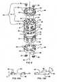
- FIGS. 1 and 4show central rod member 40 having first or superior threaded portion 41 and a second or inferior threaded portion 42 with the two threaded portions having opposing thread configurations. This means that when first threaded portion 41 is constructed with right-handed threads, second threaded portion 42 is constructed with left-handed threads. It should be understood to those skilled in the art that the vice-versa thread configuration is also contemplated.
- Central rod member 40further includes a central axis 46 that passes from first threaded portion 41 to second threaded portion 42 with a gear wheel portion 43 being positioned intermediate first threaded portion 41 and second threaded portion 42.
- Gear wheel portion 43is generally constructed with a toothed face surface 44, the plane of toothed face surface 44 being oriented substantially perpendicular to central axis 46. Collar element 47 is positioned adjacent to tooth face surface 44 to ensure proper external access of tooth face surface 44 within middle chamber 36 following assembly of vertebral body replacement device 10. Further, gear wheel portion 43 includes support surface 45 that is located on the inferior aspect or underside of gear wheel portion 43. Similar to that described for toothed wheel surface 44, the plane of support surface 45 is correspondingly oriented substantially perpendicular to central axis 46. As explained previously, support surface 45 will contact and slidingly articulate with bearing surface 51 of support ring 50 (see FIG. 1 ) when vertebral body replacement device 10 is assembled and in use.
- Gear wheel portion 43is integral to central rod member 40 and is positioned so that when gear wheel portion 43 is moved about its rotational axis, first threaded portion 41 and second threaded portion 42 will also rotate because gear wheel portion 43 axis of rotation is coaxial with central axis 46.
- FIGS. 1 , 2A and 2Bdepict end member 20.
- Vertebral body replacement device 10includes in its construct at least two end members 20, with the first one end member 20 being positioned superiorly relative to body member 30 and the second end member 20 being positioned inferiorly relative to body member 30.
- superiorly positioned first end member 20is aligned and concentric with first end receptacle 33 so that when first end member 20 moves relative to body member 30, an internal wall 23 of end member 20 is continuously positioned adjacent to outer wall 32 of first end receptacle 33.
- inferiorly positioned second end member 20as it will be aligned and concentric with second end receptacle 34 so that when second end member 20 moves relative to body member 30, internal wall 23 of end member 20 is continuously positioned adjacent to outer wall 32 of second end receptacle 34.
- end memberincludes an inner portion 21 that is bounded by internal wall 23 and a centrally positioned threaded housing element 28.
- Threaded housing element 28is constructed with internal threads 29 that may extend the full length of threaded housing element 28. Internal threads 29 are configured to correspondingly threadingly engage threaded portions 41, 42 of central rod member 40 upon assembly of vertebral body replacement device 10.
- internal wall 23also includes at least one channel 25 (see FIG. 1 ) with at least one channel 25 being oriented substantially vertical and is sized to receive corresponding at least one anti-rotational rib 35 of body member 30 when vertebral body replacement device 10 is assembled.
- end member 20has an external wall 22, through which at least one hole 27 passes to adjacent internal wall 23.
- At least one hole 27is sized to allow for the placement of bone graft material and other biocompatible materials for the purpose of facilitating a bone fusion bed following implantation.
- end wall 24functions to cap or bound inner portion 21 at one end of end member 20.
- End wall 24is integrally coupled to threaded housing element 28 and generally includes at least one projection 26 or engagement element that extends in an outward direction from the outer surface of end wall 24.
- At least one projection 26may be configured as a tooth-like body (as shown in FIGS. 1 , 2A , 2B , and 5 ) although other shaped projections or engagement elements are contemplated including, but not limited to spikes, pegs, grids, fingers and posts.
- At least one projection 26is sized to allow for operative engagement with the adjacent vertebral body, more specifically with the anatomic end plate of the vertebral body to provide adequate fixation post-implantation and to withstand any torsional loads that may be applied to end member 20 following implantation and during the lengthening procedure of vertebral body replacement device 10.
- FIG. 2Ashows, end wall 24 being oriented perpendicular or normal relative to external wall 22.
- FIG. 2Bshows an alternative embodiment of end member 20 with end wall 24 being oriented at an angle a and relative to external wall 22. Having end wall 24 being angled provides the operating surgeon with the ability to treat clinically, lordotic and kyphotic deformities. It should be well understood to those skilled in the art that end member 20 will be offered in a wide range of degrees of angulations in varying increments from 0° to 20°, thereby providing the operating surgeon with the ability to precisely treat any deformity presented during a surgical procedure.
- vertebral body replacement device 10may include an alternative embodiment of end member 90, with end wall 94 being configured to couple a footplate member 80.
- End wall 94may further include at least one alignment tab 91 that functions to orient footplate member 80 in the preferred position relative to end member 90 and a vertebral body following implantation.
- footplate member 80will be available in a plurality of various circular, non-circular and polygonal outer profile shapes, (i.e., circular as shown in FIG. 9 , oval as shown in FIG. 11A , kidney as shown in FIG. 11B or oblong (not shown)) and sizes.
- footplate member 80will be available in varying thicknesses or heights T as seen in FIG. 10A . Having a kit or implant system that includes a range of various sized heights, shapes, sizes and angled footplate members 80 provides the operating surgeon with multiple choices to maximum bone coverage, spine alignment and resulting stability of the device relative to the adjacent vertebral body following implantation.
- an end surface 82may be configured in a neutral or normal orientation relative to a sidewall 83 of footplate member 80.
- FIG. 10Bshows footplate member 80 having end surface 82 being angled (angle ⁇ ) relative to sidewall 83.
- the operating surgeonwill be provided with a plurality of footplate members 80 each having a different angle, with angulation ranging from 0° to 20°. Having such a wide range of incrementally angled footplate members 80 available will provide the operating surgeon with the ability to customize the vertebral body replacement device 10 during the operative procedure to meet the presented clinical deformity.
- FIG. 10Aan end surface 82 may be configured in a neutral or normal orientation relative to a sidewall 83 of footplate member 80.
- FIG. 10Bshows footplate member 80 having end surface 82 being angled (angle ⁇ ) relative to sidewall 83.
- the operating surgeonwill be provided with a plurality of footplate members 80 each having a different angle, with angulation ranging from 0° to 20°.
- footplate member 80may be modular in design, thereby allowing the operating surgeon to mix and match and interchange footplate members 80 with end member 90. This is accomplished by securely attaching and allowing detachment of footplate member 80 from end wall 94 of end member 90 by use of a locking mechanism 84.
- locking mechanism 84may consist of at least one locking screw 85 that passes through a hole 87 in end surface 82 to engage corresponding threaded holes 92 in end wall 94.
- footplate member 80will also include at least one projection 86 or engagement element that extends outwardly from the end surface 82.
- At least one projection 86may be configured as a tooth-like projection (as shown in FIGS. 9, 10A, and 10B ,) although other shaped engagement elements are contemplated, including but not limited to, spikes, pegs, grids, figures and posts.
- End surface 82may be treated or coated with certain materials to facilitate bio-ingrowth with the adjacent vertebral body following implantation.
- end surface 82may also undergo a process or treatment that results in end surface 82 having nano-sized or micron-sized surface features.
- footplate member 80may have an orientation mechanism 93 that may include alignment slots 88 that slidingly engage corresponding tabs 91 positioned around the peripheral of end member 90. Orientation mechanism 93 functions to securely orient footplate member 80 relative to end wall 94 and the adjacent vertebral body.
- first end member 20 and second end member 20are both positioned with each respective inner portion 21 and threaded housing element 28 within first end receptacle 33 and second end receptacle 34, respectively.
- first end member 20 and second end member 20may be simultaneously extended or retracted in an axial direction relative to body member 30 resulting in either the lengthening or shortening of the over-all length of vertebral body replacement device 10 by inserting a tool 70 through tool port hole 39 to engage the gear shaped tip (not shown) of tool 70 with tooth faced surface 44 of gear wheel portion 43 of central rod member 40.
- tool 70is rotated causing gear wheel portion 43 to rotate resulting in first and second threaded portions 41, 42 rotating about central axis 46.
- threaded housing element 28 of first and second end members 20are threaded onto first and second threaded portions 41, 42 of central rod member 40 respectively, with at least one channel 25 of first and second end members 20 also engaging at least one anti-rotational rib 35 positioned on outer wall 32 of first and second end receptacles 33, 34, respectively.
- the engagement of at least one channel 25 of first and second end members 20 with at least one rib 35 of body member 30prohibits rotational movement of the first and second end members 20 when tool 70 is turned, thus resulting in first and second end members 20 simultaneously advancing or moving in opposing axial directions relative to body member 30 for a maximum distance equal to the thread length of first and second thread portions 41, 42 of central rod member 40.
- the bidirectional axial motion of the first end and second end members 20is caused by the opposing threads (i.e., right-handed and left handed threads) of the respective first and second threaded portion 41, 42 of the central rod member 40.
- central rod member 40converts the rotational motion of tool 70 and gear wheel portion 43 into corresponding axial or linear movement of first and second end members 20, with the mating of channel 25 and rib 35 substantially prohibiting any rotational movement of two end members 20 relative to longitudinal axis 72 and the adjacent vertebrae, thus eliminating torsional forces being applied to the end member- vertebral body interface.
- FIG. 5shows an assembled vertebral body replacement device 10 following partial simultaneous movement of first and second end members 20 as describe above.
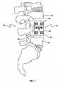
- FIG. 8shows assembled vertebral body replacement device 10 positioned within a space between two vertebral bodies following simultaneous movement of first and second end members 20 in the manner described above, resulting in intimate contact between an adjacent vertebral body and at least one projection 26 extending from end wall 24, or alternatively, projection 86 of footplate member 80 (not shown).
- a resultant compressive forceis applied by each end member 20 (or footplate member 80) against the contacted vertebral body to maintain the desired anatomic spacing.
- the surgical technique for implantation of a vertebral body replacement deviceis well known in the art, including the appropriate surgical exposure and dissection techniques.
- the methodincludes, obtaining a vertebral body replacement device 10 that may include body member 30, central rod member 40 that has two threaded portions 41, 42 and is configured to be operatively associated within body member 30 and first and second end members 20 that are configured to threadingly engage the two threaded portions 41, 42 of central rod member 40.
- body member 30 and end members 20are further configured to inhibit rotational movement of two end members 20 following assembly and positioning of vertebral body replacement device 10 within a space within a spinal column with both end members 20 engaging respective vertebral bodies when central rod member 40 is rotationally actuated, thus causing two end members 20 to move in opposing axial directions relative to body member 30. Upon such movement, two end members 20 will apply a force to the two adjacent vertebral bodies within the spinal column. It should be understood that all of the above noted device components and respective elements include the same structural and functionality characteristics as described previously herein.
- the methodmay further include the step of positioning vertebral body replacement device 10 between two vertebral bodies within a patient's spinal column.
- the surgical methodmay also include the step of simultaneously operatively moving in opposing directions both end members 20 relative to body member 30 to produce a force against the two respective adjacent vertebral bodies for the purpose of maintaining a space between the two vertebral bodies within the spinal column as shown in FIG. 8 .
- the methodmay further include the step of engaging tool 70 with central rod member 40 through tool portal hole 39, whereby rotary motion of tool 70 is converted into opposing axial movement of two respective end members 20 relative to body member 30 causing two end members 20 to come in contact and apply a force to the adjacent vertebral bodies, thereby maintaining the space between these two vertebral bodies.
- the methodalso may include the step of securely coupling to body member 30 a lock pin through lock pin hole 71 following finalization of the length adjustment procedure to ensure securement of two end members 20 relative to body member 30 and central rod member 40.
- the surgical method described hereinmay also include alternatively, using the modular footplate member 80 that has been coupled to alternative embodiment end member 90 which has been more fully described above.
- the sequence of implantation of vertebral body replacement device 10 as described hereinmay be different depending upon the given clinical situation and whether footplate members 80 are attached on the "back table" prior to the complete assembly of vertebral body replacement device 10 or within the operative site.
- the sequence of device assemblywill be at the discretion of the operating surgeon and will vary depending upon the preference of the operating surgeon in combination with the clinical needs of the patient.
- an implant systemcomprised of various cross-sectional sizes, cross-sectional polygonal and circular/oval shapes and longitudinal lengths of body members 30, end members and footplate member 80 will be available as a kit. This will allow the operating surgeon to pick and choose the separate member components to assemble vertebral body replacement device 10 that best fits into a certain spinal segment or to address an anatomical deformity presented in a patient. It should be understood by those skilled in the art that each shaped and dimensioned member provided will function in the same manner as described previously herein with central rod member 40 and supporting ring 50.
Landscapes
- Health & Medical Sciences (AREA)
- Orthopedic Medicine & Surgery (AREA)
- Engineering & Computer Science (AREA)
- Transplantation (AREA)
- Biomedical Technology (AREA)
- Heart & Thoracic Surgery (AREA)
- Oral & Maxillofacial Surgery (AREA)
- Cardiology (AREA)
- Vascular Medicine (AREA)
- Life Sciences & Earth Sciences (AREA)
- Animal Behavior & Ethology (AREA)
- General Health & Medical Sciences (AREA)
- Public Health (AREA)
- Veterinary Medicine (AREA)
- Physical Education & Sports Medicine (AREA)
- Neurology (AREA)
- Prostheses (AREA)
Description
- The present invention relates generally to orthopaedic and neurosurgical implants used for insertion within the spine, and more specifically, but not exclusively, concerns devices implanted within the spinal column to replace a resected, fractured or diseased vertebral body and to maintain or reestablish proper spacing between the remaining adjacent vertebral bodies.
- Damage or disease that affects the integral structure of a vertebral body within an individual's spinal column may lead to neurologic impairment with possible permanent damage to the spinal cord as well as improper neck and back alignment. Maintaining anatomic spacing within the spinal column is critical to ensuring continued functionality of the spinal cord and nerve roots and avoidance of long term serious neurological impairment.
- Typically, spinal implants that are used as a spacer type of device have a fixed overall length and are implanted without the ability to adjust the degree of expansion or curvature. Recent developments of spinal spacers have resulted in devices that may be lengthened in vivo by rotary motion to match the space presented by the missing vertebral body. Problems that have been seen with these types of designs include post-placement migration attributable to the torsional forces applied to the implant during the lengthening process risking the patient to neurologic injury, the improper sizing of the implant relative to the presented clinical space, limited device access ports for height manipulation, and the lack of endplate angulation possibilities.
Document DE 44 09 392 A1 discloses a vertebral body being adjustable in its height. The vertebra has a sleeve and, viewed in the axial direction, a first abutment member and a second abutment member provided respectively on each side of the sleeve. The abutment members are secured against rotation in the sleeve and displaceable in the axial direction. A threaded arrangement is provided which engages with the abutment members in order to move them coaxially.- Advancement of the state of spinal implants and the surgical management relating to the clinical presentation of missing or damaged vertebral bodies within an intact spinal column is believed desirable.
- It is the object of the present invention to provide improvements to a vertebral space implant used to treat patients suffering from either diseased or damaged vertebral bodies by providing an in vivo adjustable vertebral body replacement device for use within a spinal column that eliminates torsional forces being applied at the implant vertebral body interface, maintains the desired optimized height, and offers 360 degrees of adjustment tool access for allowing lengthening and shortening of the device in vivo.
- The object of the invention is achieved by a vertebral body replacement device according to claim 1. Advantageous embodiments are carried out according to the dependent claims.
- The vertebral body replacement device has a body member that includes an inner wall and an outer wall. The vertebral body replacement device also includes a central rod member that has two threaded portions; the central rod member is configured to be operatively associated within the body member. The vertebral body replacement further includes two end members with both end members being constructed to threadingly engage the two respective threaded portions of the central rod member. The body member and the two end members are constructed to inhibit rotational movement of the end members when the vertebral body replacement device is placed in a space within a spinal column. The end members will come into contact with adjacent vertebral bodies when the central rod member is rotated to cause movement of each end member in an axial direction relative to the body member, thereby causing the end members to apply a force to the two vertebral bodies to maintain the space between the vertebral bodies within the spinal column.
- Further, additional features and advantages are realized through the techniques of the present invention. Other embodiments and aspects of the invention are described in detail herein and are considered a part of the claimed invention.
- The subject matter which is regarded as the invention is particularly pointed out and distinctly claimed in the claims at the conclusion of the specification. The foregoing and other objects, features and advantages of the invention are apparent from the following detailed description taken in conjunction with the accompanying drawings in which:
FIG. 1 is a perspective, exploded view of one embodiment of a vertebral body replacement device, in accordance with an aspect of the present invention;FIG. 2A is a cross-sectional, side elevational view of an end member of the vertebral body replacement device ofFIG. 1 taken along line 2-2, showing an inner portion with a surrounding external wall, an internal wall and an end wall with the inner portion including a centrally oriented threaded housing element configured to engage a central rod member with the end wall being oriented normal relative to the external wall, in accordance with an aspect of the present invention;FIG. 2B is a cross-sectional, side elevational view of an alternative embodiment of an end member, showing an inner portion with a surrounding external wall, an internal wall and an end wall with the inner portion including a centrally oriented threaded housing element configured to engage a central rod member with the end wall being oriented at an angle relative to the external wall, in accordance with an aspect of the present invention;FIG. 3 is a cross-sectional, side elevational view of a body member of the vertebral body replacement device ofFIG. 1 taken along line 3-3, showing two receptacle ends and internal threads for engaging a support ring, in accordance with an aspect of the present invention;FIG. 4 is a side elevational view of a central rod member of the vertebral body replacement device ofFIG. 1 , in accordance with an aspect of the present invention;FIG. 5 is a side elevational view of the assembled vertebral body replacement device ofFIG. 1 , showing a superiorly positioned end member and an inferiorly positioned end member extended away from the body member, in accordance with an aspect of the present invention;FIG. 6 is a perspective view of the vertebral body replacement device ofFIG. 1 , with a tool inserted through a tool port hole and in operable position with the central rod member, in accordance with an aspect of the present invention;FIG. 7 is a side elevational view of the vertebral body replacement device ofFIG. 1 , shown disposed within a space between two vertebral bodies within a spinal column prior to the translational movement of the superiorly positioned end member and the inferiorly positioned end member, in accordance with an aspect of the present invention;FIG. 8 is a side elevational view of the vertebral body replacement device ofFIG. 1 , shown positioned between two vertebral bodies with the superiorly positioned end member and the inferiorly positioned end member extended to maintain a desired space within a spinal column, in accordance with an aspect of the present invention;FIG. 9 is a perspective view of an alternative embodiment of a vertebral body replacement device, with a superiorly positioned, detachable footplate member and an inferiorly positioned, detachable footplate member shown prior to being coupled to the superiorly positioned end member and an inferiorly positioned end member, respectively, in accordance with an aspect of the present invention;FIG. 10A is a side elevational view of a detachable footplate member of the vertebral body replacement device ofFIG. 9 , showing an end surface being oriented normal relative to a sidewall, in accordance with an aspect of the present invention; andFIG. 10B is a side elevational view of an alternative embodiment of a detachable footplate member used with the vertebral body replacement device ofFIG. 9 , showing the end surface being oriented at an angle relative to the sidewall, in accordance with an aspect of the present invention.FIG. 11A is a perspective view of an alternative embodiment of a detachable foot plate member used with the vertebral body replacement device ofFIG. 9 , showing the end surface having an outer oval shaped profile, in accordance with an aspect of the present invention; andFIG. 11B is a perspective view of an alternative embodiment of a detachable footplate member used with the vertebral body replacement device ofFIG. 9 , showing the end surface having an outer kidney shaped profile, in accordance with an aspect of the present invention.- Generally stated, disclosed herein is a vertebral body replacement device or vertebral spacer that typically includes a body member, a central rod member, a support ring, two end members and at least one footplate member. As used herein, the terms "vertebral body replacement device" and "vertebral spacer" may be used interchangeable as they essentially describe the same type of implant device. Further, described herein is a surgical method for using the vertebral body replacement device to maintain a space between two vertebral bodies within a patient suffering from a diseased or damaged spinal column.
- As depicted in
FIG. 1 , the general arrangement of a vertebralbody replacement device 10, in accordance with an aspect of the present invention, includes abody member 30, at least twoend members 20, acentral rod member 40 and asupport ring 50. In this detailed description and the following claims, the words proximal, distal, anterior, posterior, medial, lateral, superior and inferior are defined by their standard usage for indicating a particular part of a bone or prosthesis according to the relative disposition of the natural bone or directional terms of reference. For example, "proximal" means the portion of a prosthesis nearest the torso, while "distal" indicates the portion of the prosthesis farthest from the torso. As for directional terms, "anterior" is a direction towards the front side of the body, "posterior" means a direction towards the back side of the body, "medial" means towards the midline of the body, "lateral" is a direction towards the sides or away from the midline of the body, "superior" means a direction above and "inferior" means a direction below another object or structure. - With reference to
FIG. 1 , vertebralbody replacement device 10 includesbody member 30, at least twoend members 20 positioned superior and inferior relative tobody member 30, acentral rod member 40 for placement withinbody member 30 and supportring 50 that is configured to contact and securecentral rod member 40 withinbody member 30. - Exhibited in
FIG. 1 ,body member 30 also includes aninner wall 31 and anouter wall 32, at least onehole 38 extending fromouter wall 32 throughinner wall 31. Further,body member 30 has at least oneanti-rotational rib 35 disposed on and extending for substantially the entire length ofouter wall 32. At least onerib 35 is oriented in a superior to inferior direction relative tobody member 30 and substantially parallel to alongitudinal axis 72 ofbody member 30. At least onehole 38 is used for the placement of bone graft or other biocompatible material that will facilitate bone fusion to occur in vivo following implantation of the device. It should be understood to those skilled in the art thatbody member 30 may be available to the operating surgeon in various outside diameter sizes and longitudinal lengths L (seeFIG. 3 ). Having multiple sizedbody members 30 as part of an implant system allows the operating surgeon to use vertebralbody remplacement device 10 in various levels or segments of the spine (i.e., smaller sizes in the cervical spine, medium sizes in the thoracic spine and larger sizes in the lumbar spine). - As shown in the cross-sectional view of
FIG. 3 ,body member 30 further includes a first or superiorly positionedend receptacle 33 and a second or inferiorly positionedend receptacle 34 withlongitudinal axis 72 extending between these two structures withinelongate body member 30. Amiddle chamber 36 is defined byinner wall 31 and is bound superiorly byfirst end receptacle 33 and inferiorly bysecond end receptacle 34. At least onetool port hole 39 extends intomiddle chamber 36 throughouter wall 32 andinner wall 31. In addition,inner wall 31 ofmiddle chamber 36 includes a set ofinternal threads 37 positioned in the bottom portion ofmiddle chamber 36. Internal threads are sized and configured to threadingly engage the external threads 52 of support ring 50 (not shown). Aceiling surface 74 bounds the superior portion ofmiddle chamber 36 with a centralized opening 75 positioned throughceiling surface 74. Although not shown, when vertebralbody replacement device 10 is fully assembled and in use,central rod member 40 is operatively associated withbody member 30 by being configured to allow for a superior threadedportion 41 ofcentral rod member 40 to pass through centralized opening 75 resulting in acollar element 47 ofcentral rod member 40 contactingceiling surface 74. Following placement of superior threadedportion 41 ofcentral rod member 40 through centralized opening 75,central rod member 40 is moveably secured withinmiddle chamber 36 by threadinglycoupling support ring 50 tointernal threads 37 ofmiddle chamber 36 resulting in a bearing surface 51 ofsupport ring 50 making pressing contact with asupport surface 45 ofcentral rod member 40.Body member 30 further includes at least one locking pin hole 71 (as seen inFIG. 1 ) that passes throughouter wall 32 andinner wall 31 intomiddle chamber 36. Although not shown, following final placement and adjustment of assembled vertebralbody replacement device 10, a corresponding threaded pin or bolt may screw into at least onelocking pin hole 71 resulting incentral rod member 40 being secured in position, fixing the overall length ofvertebral body replacement 10. FIGS. 1 and4 showcentral rod member 40 having first or superior threadedportion 41 and a second or inferior threadedportion 42 with the two threaded portions having opposing thread configurations. This means that when first threadedportion 41 is constructed with right-handed threads, second threadedportion 42 is constructed with left-handed threads. It should be understood to those skilled in the art that the vice-versa thread configuration is also contemplated.Central rod member 40 further includes acentral axis 46 that passes from first threadedportion 41 to second threadedportion 42 with agear wheel portion 43 being positioned intermediate first threadedportion 41 and second threadedportion 42.Gear wheel portion 43 is generally constructed with atoothed face surface 44, the plane oftoothed face surface 44 being oriented substantially perpendicular tocentral axis 46.Collar element 47 is positioned adjacent totooth face surface 44 to ensure proper external access oftooth face surface 44 withinmiddle chamber 36 following assembly of vertebralbody replacement device 10. Further,gear wheel portion 43 includessupport surface 45 that is located on the inferior aspect or underside ofgear wheel portion 43. Similar to that described fortoothed wheel surface 44, the plane ofsupport surface 45 is correspondingly oriented substantially perpendicular tocentral axis 46. As explained previously,support surface 45 will contact and slidingly articulate with bearing surface 51 of support ring 50 (seeFIG. 1 ) when vertebralbody replacement device 10 is assembled and in use.Gear wheel portion 43 is integral tocentral rod member 40 and is positioned so that whengear wheel portion 43 is moved about its rotational axis, first threadedportion 41 and second threadedportion 42 will also rotate becausegear wheel portion 43 axis of rotation is coaxial withcentral axis 46.FIGS. 1 ,2A and 2B depictend member 20. Vertebralbody replacement device 10 includes in its construct at least twoend members 20, with the first oneend member 20 being positioned superiorly relative tobody member 30 and thesecond end member 20 being positioned inferiorly relative tobody member 30. In operation, superiorly positionedfirst end member 20 is aligned and concentric withfirst end receptacle 33 so that whenfirst end member 20 moves relative tobody member 30, aninternal wall 23 ofend member 20 is continuously positioned adjacent toouter wall 32 offirst end receptacle 33. The same operational relationship occurs with inferiorly positionedsecond end member 20 as it will be aligned and concentric withsecond end receptacle 34 so that whensecond end member 20 moves relative tobody member 30,internal wall 23 ofend member 20 is continuously positioned adjacent toouter wall 32 ofsecond end receptacle 34.- As seen in
FIGS. 2A and 2B , end member includes aninner portion 21 that is bounded byinternal wall 23 and a centrally positioned threadedhousing element 28. Threadedhousing element 28 is constructed withinternal threads 29 that may extend the full length of threadedhousing element 28.Internal threads 29 are configured to correspondingly threadingly engage threadedportions central rod member 40 upon assembly of vertebralbody replacement device 10. Although not shown inFIGS. 2A and 2B ,internal wall 23 also includes at least one channel 25 (seeFIG. 1 ) with at least onechannel 25 being oriented substantially vertical and is sized to receive corresponding at least oneanti-rotational rib 35 ofbody member 30 when vertebralbody replacement device 10 is assembled. - As further shown in the cross-sectional views of
FIGS. 2A and 2B ,end member 20 has anexternal wall 22, through which at least onehole 27 passes to adjacentinternal wall 23. At least onehole 27 is sized to allow for the placement of bone graft material and other biocompatible materials for the purpose of facilitating a bone fusion bed following implantation. - Additionally, as seen in
FIGS. 1 and2A ,end wall 24 functions to cap or boundinner portion 21 at one end ofend member 20.End wall 24 is integrally coupled to threadedhousing element 28 and generally includes at least oneprojection 26 or engagement element that extends in an outward direction from the outer surface ofend wall 24. At least oneprojection 26 may be configured as a tooth-like body (as shown inFIGS. 1 ,2A ,2B , and5 ) although other shaped projections or engagement elements are contemplated including, but not limited to spikes, pegs, grids, fingers and posts. At least oneprojection 26 is sized to allow for operative engagement with the adjacent vertebral body, more specifically with the anatomic end plate of the vertebral body to provide adequate fixation post-implantation and to withstand any torsional loads that may be applied to endmember 20 following implantation and during the lengthening procedure of vertebralbody replacement device 10. - Cross-section view of
FIG. 2A shows,end wall 24 being oriented perpendicular or normal relative toexternal wall 22.FIG. 2B shows an alternative embodiment ofend member 20 withend wall 24 being oriented at an angle a and relative toexternal wall 22. Havingend wall 24 being angled provides the operating surgeon with the ability to treat clinically, lordotic and kyphotic deformities. It should be well understood to those skilled in the art that endmember 20 will be offered in a wide range of degrees of angulations in varying increments from 0° to 20°, thereby providing the operating surgeon with the ability to precisely treat any deformity presented during a surgical procedure. - As shown in
FIG. 9 , it is contemplated that, vertebralbody replacement device 10 may include an alternative embodiment ofend member 90, withend wall 94 being configured to couple afootplate member 80.End wall 94 may further include at least onealignment tab 91 that functions to orientfootplate member 80 in the preferred position relative to endmember 90 and a vertebral body following implantation. As seen inFIGS. 11A and 11B , it is contemplated thatfootplate member 80 will be available in a plurality of various circular, non-circular and polygonal outer profile shapes, (i.e., circular as shown inFIG. 9 , oval as shown inFIG. 11A , kidney as shown inFIG. 11B or oblong (not shown)) and sizes. It is further contemplated thatfootplate member 80 will be available in varying thicknesses or heights T as seen inFIG. 10A . Having a kit or implant system that includes a range of various sized heights, shapes, sizes andangled footplate members 80 provides the operating surgeon with multiple choices to maximum bone coverage, spine alignment and resulting stability of the device relative to the adjacent vertebral body following implantation. - As shown in
FIG. 10A , anend surface 82 may be configured in a neutral or normal orientation relative to asidewall 83 offootplate member 80. Alternatively,FIG. 10B showsfootplate member 80 havingend surface 82 being angled (angle Δ) relative to sidewall 83. As discussed above, it is contemplated that the operating surgeon will be provided with a plurality offootplate members 80 each having a different angle, with angulation ranging from 0° to 20°. Having such a wide range of incrementallyangled footplate members 80 available will provide the operating surgeon with the ability to customize the vertebralbody replacement device 10 during the operative procedure to meet the presented clinical deformity. Although shown with a circular perimeter geometry inFIG. 9 , as described previously it should be understood to those skilled in the art that both neutral andangled footplate members 80 will be constructed in multiple outer profile geometric shapes, sizes and overall thickness T, again to provide the operating surgeon with the ability to maximize bone support post-implantation.Footplate member 80 may be modular in design, thereby allowing the operating surgeon to mix and match andinterchange footplate members 80 withend member 90. This is accomplished by securely attaching and allowing detachment offootplate member 80 fromend wall 94 ofend member 90 by use of alocking mechanism 84. For example purposes only, as shown,locking mechanism 84 may consist of at least one lockingscrew 85 that passes through ahole 87 inend surface 82 to engage corresponding threadedholes 92 inend wall 94. Further, it should be understood to those skilled in the art that various other low-profile locking or securement mechanisms may also be used for this purpose including, but not limited to lock pins, bolts, and press fit pins. As described above, it is contemplated thatfootplate member 80 will also include at least oneprojection 86 or engagement element that extends outwardly from theend surface 82. At least oneprojection 86 may be configured as a tooth-like projection (as shown inFIGS. 9, 10A, and 10B ,) although other shaped engagement elements are contemplated, including but not limited to, spikes, pegs, grids, figures and posts.End surface 82 may be treated or coated with certain materials to facilitate bio-ingrowth with the adjacent vertebral body following implantation. Additionally,end surface 82 may also undergo a process or treatment that results inend surface 82 having nano-sized or micron-sized surface features. In addition,footplate member 80 may have anorientation mechanism 93 that may includealignment slots 88 that slidingly engage correspondingtabs 91 positioned around the peripheral ofend member 90.Orientation mechanism 93 functions to securely orientfootplate member 80 relative to endwall 94 and the adjacent vertebral body. - Following the assembly of vertebral
body replacement device 10, superiorly positioned orfirst end member 20 and inferiorly positioned orsecond end member 20 are both positioned with each respectiveinner portion 21 and threadedhousing element 28 withinfirst end receptacle 33 andsecond end receptacle 34, respectively. As shown inFIG. 6 ,first end member 20 andsecond end member 20 may be simultaneously extended or retracted in an axial direction relative tobody member 30 resulting in either the lengthening or shortening of the over-all length of vertebralbody replacement device 10 by inserting atool 70 throughtool port hole 39 to engage the gear shaped tip (not shown) oftool 70 with tooth facedsurface 44 ofgear wheel portion 43 ofcentral rod member 40. In operation,tool 70 is rotated causinggear wheel portion 43 to rotate resulting in first and second threadedportions central axis 46. When assembled, threadedhousing element 28 of first andsecond end members 20 are threaded onto first and second threadedportions central rod member 40 respectively, with at least onechannel 25 of first andsecond end members 20 also engaging at least oneanti-rotational rib 35 positioned onouter wall 32 of first andsecond end receptacles channel 25 of first andsecond end members 20 with at least onerib 35 ofbody member 30 prohibits rotational movement of the first andsecond end members 20 whentool 70 is turned, thus resulting in first andsecond end members 20 simultaneously advancing or moving in opposing axial directions relative tobody member 30 for a maximum distance equal to the thread length of first andsecond thread portions central rod member 40. As discussed above, the bidirectional axial motion of the first end andsecond end members 20 is caused by the opposing threads (i.e., right-handed and left handed threads) of the respective first and second threadedportion central rod member 40. Operationally,central rod member 40 converts the rotational motion oftool 70 andgear wheel portion 43 into corresponding axial or linear movement of first andsecond end members 20, with the mating ofchannel 25 andrib 35 substantially prohibiting any rotational movement of twoend members 20 relative tolongitudinal axis 72 and the adjacent vertebrae, thus eliminating torsional forces being applied to the end member- vertebral body interface. For example purposes,FIG. 5 shows an assembled vertebralbody replacement device 10 following partial simultaneous movement of first andsecond end members 20 as describe above. FIG. 8 shows assembled vertebralbody replacement device 10 positioned within a space between two vertebral bodies following simultaneous movement of first andsecond end members 20 in the manner described above, resulting in intimate contact between an adjacent vertebral body and at least oneprojection 26 extending fromend wall 24, or alternatively,projection 86 of footplate member 80 (not shown). A resultant compressive force is applied by each end member 20 (or footplate member 80) against the contacted vertebral body to maintain the desired anatomic spacing.- The surgical technique for implantation of a vertebral body replacement device is well known in the art, including the appropriate surgical exposure and dissection techniques. The method includes, obtaining a vertebral
body replacement device 10 that may includebody member 30,central rod member 40 that has two threadedportions body member 30 and first andsecond end members 20 that are configured to threadingly engage the two threadedportions central rod member 40. As discussed above,body member 30 andend members 20 are further configured to inhibit rotational movement of twoend members 20 following assembly and positioning of vertebralbody replacement device 10 within a space within a spinal column with bothend members 20 engaging respective vertebral bodies whencentral rod member 40 is rotationally actuated, thus causing twoend members 20 to move in opposing axial directions relative tobody member 30. Upon such movement, twoend members 20 will apply a force to the two adjacent vertebral bodies within the spinal column. It should be understood that all of the above noted device components and respective elements include the same structural and functionality characteristics as described previously herein. - As seen in
FIG. 7 , the method may further include the step of positioning vertebralbody replacement device 10 between two vertebral bodies within a patient's spinal column. The surgical method may also include the step of simultaneously operatively moving in opposing directions bothend members 20 relative tobody member 30 to produce a force against the two respective adjacent vertebral bodies for the purpose of maintaining a space between the two vertebral bodies within the spinal column as shown inFIG. 8 . Although not shown, the method may further include the step of engagingtool 70 withcentral rod member 40 through toolportal hole 39, whereby rotary motion oftool 70 is converted into opposing axial movement of tworespective end members 20 relative tobody member 30 causing twoend members 20 to come in contact and apply a force to the adjacent vertebral bodies, thereby maintaining the space between these two vertebral bodies. The method also may include the step of securely coupling to body member 30 a lock pin throughlock pin hole 71 following finalization of the length adjustment procedure to ensure securement of twoend members 20 relative tobody member 30 andcentral rod member 40. - It should be understood by those skilled in the art that the surgical method described herein may also include alternatively, using the
modular footplate member 80 that has been coupled to alternativeembodiment end member 90 which has been more fully described above. The sequence of implantation of vertebralbody replacement device 10 as described herein may be different depending upon the given clinical situation and whetherfootplate members 80 are attached on the "back table" prior to the complete assembly of vertebralbody replacement device 10 or within the operative site. The sequence of device assembly will be at the discretion of the operating surgeon and will vary depending upon the preference of the operating surgeon in combination with the clinical needs of the patient. - It is further contemplated that an implant system comprised of various cross-sectional sizes, cross-sectional polygonal and circular/oval shapes and longitudinal lengths of
body members 30, end members andfootplate member 80 will be available as a kit. This will allow the operating surgeon to pick and choose the separate member components to assemble vertebralbody replacement device 10 that best fits into a certain spinal segment or to address an anatomical deformity presented in a patient. It should be understood by those skilled in the art that each shaped and dimensioned member provided will function in the same manner as described previously herein withcentral rod member 40 and supportingring 50. - Although the preferred embodiments have been depicted and described in detail herein, it will be apparent to those skilled in the relevant art that various modifications, additions and substitutions can be made without departing from the scope of the following claims.
Claims (15)
- A vertebral body replacement device (10) comprising:a body member (30) having an inner wall (31) and an outer wall (32);a central rod member (40) having a first threaded portion (41) and a second threaded portion (42), the central rod member being configured to be operatively associated within the body member (30);a first end member (20) and a second end member (20), the first end member being configured to threadingly engage the first threaded portion (41) of the central rod member (40) and the second end member being configured to threadingly engage the second threaded portion (42) of the central rod member; anda support ring (50) having a bearing surface (51) in contact with the central rod member (40) when the central rod member is operatively positioned within the body member (40),wherein the body member (30), and first and second end members (20) are configured to inhibit rotational movement of the first and second end members when the vertebral body replacement device (10) is disposed within a space within a spinal column with the first and second end members engaging respective vertebral bodies of the spinal column and the central rod member (40) is rotationally actuated to move the first end member and the second end member in an axial direction relative to the body member allowing for the first end member and the second end member to apply a force to the two vertebral bodies to maintain a desired space therebetweencharacterized in thatthe central rod member (40) further comprises a gear wheel portion (43), the gear wheel portion having a toothed face- surface (44) and a support surface (45), the support surface of the gear wheel portion being configured to contact the bearing surface (51) of the support ring (50) when the central rod member is operatively positioned within the body member,the outer wall (32) of the body member (30) has at least one rib (35) disposed thereon,the first end member (20) and the second end member (20) each having a channel (25) disposed on an inner wall (23),wherein the channel (25) of the first and second end members (20) matingly engages the at least one rib (35) disposed on the outer wall (32) of the body member (30).
- The vertebral body replacement device of claim 1, wherein the body member (30) is an elongate body comprising a first end receptacle (33), a second end receptacle (34), and a longitudinal axis (72) extends between the first end receptacle and the second end receptacle thereof.
- The vertebral body replacement device of claim 2, wherein the at least one rib (35) being disposed along the outer wall (32) of the body member runs substantially parallel to the longitudinal axis (72).
- The vertebral body replacement device of claim 3, wherein the first end member (20) and the second end member (20) each further comprising an external wall (22), the internal wall (23), and an end wall (24), wherein each of the first end member and the second end member have the channel (25). disposed on the internal wall extending from the end well along at least a portion of the length of the internal well with the channel being oriented and positioned to engage the at least one rib (35) of the body member (30) when the first end member is operatively associated with the first end receptacle (33) and the second end member is operatively associated with the second end receptacle (34).
- The vertebral body replacement device of claim 1, wherein the central rod member (40) further comprises a central axis (46) extending between the first threaded portion (41) and the second threaded portion (42) thereof, and wherein the rotational axis of the gear wheel portion (43) is substantially coaxial to the central axis of the central rod member, thereby when the gear wheel portion is rotated about the rotational axis, the first and second threaded portions correspondingly rotate about the central axis of the central rod member.
- The vertebral body replacement device of claim 1, further comprising at least one footplate member (80), wherein the at least one footplate member couples to at least one of the first end member (20) and the second end member (20), and is sized and configured to allow for maximum contact with the two vertebral bodies when the vertebral body replacement device (10) is positioned within the space within the spinal column.
- The vertebral body replacement device of claim 4, wherein for at least one of the first end member (20) and the second end member (20) at least one projection (26) is disposed on the end wall (24) and extends in an outward direction from each end wall to engage the respective two vertebral bodies when the vertebral body replacement device is in use within the spinal column.
- The vertebral body replacement device of claim 4, wherein for at least one of the first end member (20) and the second end member (20), the end wall (24) is disposed normal or at an angle relative to the external wall (22).
- The vertebral body replacement device of claim 4, wherein for each of the first end member (20) and the second end member (20), the first end member and the second end member further comprise at least one hole (27, 81) disposed in at least one of the external wall (22) and the end wall (24) and extending therethrough, thereby allowing for the placement of bio-compatible material within the first and second end members.
- The vertebral body replacement device of claim 1, the body member (30) further comprising at least one hole (38) extending from the outer wall (32) through the inner wall (31) therethrough, thereby allowing for the placement of bio-compatible material within the body member.
- The vertebral body replacement device of claim 6, wherein the at least one footplate (80) comprises an end surface (82) and a sidewall (83), the end surface disposed normal or at an angle relative to the side wall.
- The vertebral body replacement device of claim 11, wherein the end surface (82) of the at least one footplate member (80) is adjacent the side surface (83).
- The vertebral body replacement device of claim 1, the body member (30) comprises a tool port (39) through which a tool may be inserted to engage the toothed face surface (44) of gear wheel portion (43) of central rod member (40).
- The vertebral body replacement device of claim 1, wherein the first and second threaded portions (41 and 42) have opposing threaded configurations relative to each other, such that when the gear wheel portion (43) is rotated, the first and second threaded portions rotate, resulting in the first and second end members (20) simultaneously moving in opposite axial directions relative to the body member (30).
- The vertebral body replacement device of claim 1, wherein a plane of the toothed face surface (44) and a plane of the support surface (45) of the central rod member (40) are oriented substantially perpendicular to a central axis (46) of the central rod member.
Applications Claiming Priority (2)
| Application Number | Priority Date | Filing Date | Title |
|---|---|---|---|
| US11/928,532US8182537B2 (en) | 2007-10-30 | 2007-10-30 | Vertebral body replacement device and method for use to maintain a space between two vertebral bodies within a spine |
| PCT/US2008/080143WO2009058578A1 (en) | 2007-10-30 | 2008-10-16 | Vertebral body replacement device and method for use to maintain a space between two vertebral bodies within a spine |
Publications (2)
| Publication Number | Publication Date |
|---|---|
| EP2209441A1 EP2209441A1 (en) | 2010-07-28 |
| EP2209441B1true EP2209441B1 (en) | 2014-10-15 |
Family
ID=40225206
Family Applications (1)
| Application Number | Title | Priority Date | Filing Date |
|---|---|---|---|
| EP08844082.1ANot-in-forceEP2209441B1 (en) | 2007-10-30 | 2008-10-16 | Vertebral body replacement device |
Country Status (5)
| Country | Link |
|---|---|
| US (1) | US8182537B2 (en) |
| EP (1) | EP2209441B1 (en) |
| JP (2) | JP2011502005A (en) |
| AU (1) | AU2008319067B2 (en) |
| WO (1) | WO2009058578A1 (en) |
Families Citing this family (96)
| Publication number | Priority date | Publication date | Assignee | Title |
|---|---|---|---|---|
| US6793678B2 (en) | 2002-06-27 | 2004-09-21 | Depuy Acromed, Inc. | Prosthetic intervertebral motion disc having dampening |
| AU2004212942A1 (en) | 2003-02-14 | 2004-09-02 | Depuy Spine, Inc. | In-situ formed intervertebral fusion device |
| US20040267367A1 (en) | 2003-06-30 | 2004-12-30 | Depuy Acromed, Inc | Intervertebral implant with conformable endplate |
| US8636802B2 (en) | 2004-03-06 | 2014-01-28 | DePuy Synthes Products, LLC | Dynamized interspinal implant |
| EP1639968A1 (en)* | 2004-09-23 | 2006-03-29 | Cervitech, Inc. | Implant with a part to be inserted and anchored in a bone cavity |
| US8597360B2 (en) | 2004-11-03 | 2013-12-03 | Neuropro Technologies, Inc. | Bone fusion device |
| US7704279B2 (en)* | 2005-04-12 | 2010-04-27 | Moskowitz Mosheh T | Bi-directional fixating transvertebral body screws, zero-profile horizontal intervertebral miniplates, expansile intervertebral body fusion devices, and posterior motion-calibrating interarticulating joint stapling device for spinal fusion |
| ES2395298T3 (en)* | 2006-07-14 | 2013-02-11 | Biedermann Technologies Gmbh & Co. Kg | Separator for insertion between two vertebrae |
| US8920502B1 (en)* | 2006-11-08 | 2014-12-30 | Spinal Usa, Inc. | Vertebral body replacement |
| US9023107B2 (en)* | 2006-11-08 | 2015-05-05 | Spinal Usa, Inc. | Vertebral body replacement |
| WO2008070863A2 (en) | 2006-12-07 | 2008-06-12 | Interventional Spine, Inc. | Intervertebral implant |
| US8900307B2 (en) | 2007-06-26 | 2014-12-02 | DePuy Synthes Products, LLC | Highly lordosed fusion cage |
| US20090112325A1 (en)* | 2007-10-30 | 2009-04-30 | Biospine, Llc | Footplate member and a method for use in a vertebral body replacement device |
| US8142441B2 (en)* | 2008-10-16 | 2012-03-27 | Aesculap Implant Systems, Llc | Surgical instrument and method of use for inserting an implant between two bones |
| US8182537B2 (en) | 2007-10-30 | 2012-05-22 | Aesculap Implant Systems, Llc | Vertebral body replacement device and method for use to maintain a space between two vertebral bodies within a spine |
| US8591587B2 (en) | 2007-10-30 | 2013-11-26 | Aesculap Implant Systems, Llc | Vertebral body replacement device and method for use to maintain a space between two vertebral bodies within a spine |
| EP2237748B1 (en) | 2008-01-17 | 2012-09-05 | Synthes GmbH | An expandable intervertebral implant |
| US8936641B2 (en) | 2008-04-05 | 2015-01-20 | DePuy Synthes Products, LLC | Expandable intervertebral implant |
| BRPI0822953A2 (en) | 2008-09-04 | 2015-06-23 | Synthes Gmbh | Adjustable intervertebral implant |
| WO2010048396A2 (en)* | 2008-10-23 | 2010-04-29 | Linares Maedical Devices, Llc | Support insert associated with spinal vertebrae |
| US8721723B2 (en) | 2009-01-12 | 2014-05-13 | Globus Medical, Inc. | Expandable vertebral prosthesis |
| US8142435B2 (en)* | 2009-02-19 | 2012-03-27 | Aesculap Implant Systems, Llc | Multi-functional surgical instrument and method of use for inserting an implant between two bones |
| US9687357B2 (en) | 2009-03-12 | 2017-06-27 | Nuvasive, Inc. | Vertebral body replacement |
| US9387090B2 (en) | 2009-03-12 | 2016-07-12 | Nuvasive, Inc. | Vertebral body replacement |
| WO2013025448A1 (en)* | 2011-08-09 | 2013-02-21 | Nuvasive, Inc. | Vertebral body replacement |
| US9526620B2 (en) | 2009-03-30 | 2016-12-27 | DePuy Synthes Products, Inc. | Zero profile spinal fusion cage |
| KR101687435B1 (en) | 2009-07-06 | 2016-12-19 | 신세스 게엠바하 | Expandable fixation assemblies |
| US20110106258A1 (en)* | 2009-10-30 | 2011-05-05 | Warsaw Orthopedic, Inc. | End cap for a vertebral implant |
| EP2485682A4 (en)* | 2009-11-10 | 2013-10-23 | Zimmer Spine Inc | TISSUE SPACING ELEMENT IMPLANT, IMPLANTATION TOOL, AND METHODS OF USING THE SAME |
| US9393129B2 (en) | 2009-12-10 | 2016-07-19 | DePuy Synthes Products, Inc. | Bellows-like expandable interbody fusion cage |
| US20110184466A1 (en)* | 2010-01-26 | 2011-07-28 | Weiser Harry C | Spinal Instrumentation Systems and Methods of Making and Using the Same |
| US8591585B2 (en) | 2010-04-12 | 2013-11-26 | Globus Medical, Inc. | Expandable vertebral implant |
| US8870880B2 (en) | 2010-04-12 | 2014-10-28 | Globus Medical, Inc. | Angling inserter tool for expandable vertebral implant |
| US9301850B2 (en) | 2010-04-12 | 2016-04-05 | Globus Medical, Inc. | Expandable vertebral implant |
| US11426287B2 (en) | 2010-04-12 | 2022-08-30 | Globus Medical Inc. | Expandable vertebral implant |
| US9579211B2 (en) | 2010-04-12 | 2017-02-28 | Globus Medical, Inc. | Expandable vertebral implant |
| US9907560B2 (en) | 2010-06-24 | 2018-03-06 | DePuy Synthes Products, Inc. | Flexible vertebral body shavers |
| US8979860B2 (en) | 2010-06-24 | 2015-03-17 | DePuy Synthes Products. LLC | Enhanced cage insertion device |
| US8623091B2 (en) | 2010-06-29 | 2014-01-07 | DePuy Synthes Products, LLC | Distractible intervertebral implant |
| US20120078372A1 (en) | 2010-09-23 | 2012-03-29 | Thomas Gamache | Novel implant inserter having a laterally-extending dovetail engagement feature |
| US9402732B2 (en) | 2010-10-11 | 2016-08-02 | DePuy Synthes Products, Inc. | Expandable interspinous process spacer implant |
| US9084684B2 (en)* | 2010-11-06 | 2015-07-21 | Igip, Llc | Stabilizer for assisting stabilization of a spinal implant |
| US8377140B2 (en) | 2011-01-12 | 2013-02-19 | Ebi, Llc | Expandable spinal implant device |
| DE102011002076A1 (en)* | 2011-04-15 | 2012-10-18 | Z.-Medical Gmbh & Co. Kg | Intervertebral implant and device for insertion |
| WO2013023096A1 (en)* | 2011-08-09 | 2013-02-14 | Neuropro Technologies, Inc. | Bone fusion device, system and method |
| US9358123B2 (en)* | 2011-08-09 | 2016-06-07 | Neuropro Spinal Jaxx, Inc. | Bone fusion device, apparatus and method |
| US9248028B2 (en) | 2011-09-16 | 2016-02-02 | DePuy Synthes Products, Inc. | Removable, bone-securing cover plate for intervertebral fusion cage |
| US9439771B2 (en)* | 2011-10-19 | 2016-09-13 | P&H Medical Products, Llc | Laterally expandable spinal prosthesis |
| US9532883B2 (en) | 2012-04-13 | 2017-01-03 | Neuropro Technologies, Inc. | Bone fusion device |
| WO2013173682A1 (en)* | 2012-05-18 | 2013-11-21 | Aesculap Implant Systems, Llc | Vertebral body replacement device and method for use of the device with the inserting tool |
| EP2877127B1 (en) | 2012-07-26 | 2019-08-21 | Synthes GmbH | Expandable implant |
| US8715351B1 (en)* | 2012-11-29 | 2014-05-06 | Spine Wave, Inc. | Expandable interbody fusion device with graft chambers |
| US9717601B2 (en) | 2013-02-28 | 2017-08-01 | DePuy Synthes Products, Inc. | Expandable intervertebral implant, system, kit and method |
| US9522070B2 (en) | 2013-03-07 | 2016-12-20 | Interventional Spine, Inc. | Intervertebral implant |
| CA2906531C (en) | 2013-03-15 | 2020-10-06 | Neuropro Technologies, Inc. | Bodiless bone fusion device, apparatus and method |
| US9968460B2 (en) | 2013-03-15 | 2018-05-15 | Medsmart Innovation Inc. | Dynamic spinal segment replacement |
| AU2014268740B2 (en) | 2013-05-20 | 2018-04-26 | K2M, Inc. | Adjustable implant and insertion tool |
| US9566167B2 (en) | 2013-08-22 | 2017-02-14 | K2M, Inc. | Expandable spinal implant |
| US9211193B2 (en) | 2013-08-30 | 2015-12-15 | Aesculap Implant Systems, Llc | Prosthesis, system and method |
| US9808354B2 (en) | 2014-01-17 | 2017-11-07 | Stryker European Holdings I, Llc | Implant insertion tool |
| US9681961B2 (en)* | 2014-08-01 | 2017-06-20 | Warsaw Orthopedic, Inc. | Surgical instrument system and method |
| US9585762B2 (en) | 2014-10-09 | 2017-03-07 | K2M, Inc. | Expandable spinal interbody spacer and method of use |
| US10363142B2 (en) | 2014-12-11 | 2019-07-30 | K2M, Inc. | Expandable spinal implants |
| US11426290B2 (en) | 2015-03-06 | 2022-08-30 | DePuy Synthes Products, Inc. | Expandable intervertebral implant, system, kit and method |
| US9775719B2 (en) | 2015-03-23 | 2017-10-03 | Musc Foundation For Research Development | Expandable vertebral body replacement device and method |
| US9913727B2 (en) | 2015-07-02 | 2018-03-13 | Medos International Sarl | Expandable implant |
| US10188524B2 (en) | 2015-08-28 | 2019-01-29 | Aesculap Implant Systems, Llc | Rotational drive mechanism, tool and methods for using same |
| US10231756B2 (en) | 2015-08-28 | 2019-03-19 | Aesculap Implant Systems, Llc | Rotational drive mechanism, tool and methods for using same |
| US10004608B2 (en) | 2016-02-26 | 2018-06-26 | K2M, Inc. | Insertion instrument for expandable spinal implants |
| US11510788B2 (en) | 2016-06-28 | 2022-11-29 | Eit Emerging Implant Technologies Gmbh | Expandable, angularly adjustable intervertebral cages |
| EP3474784A2 (en) | 2016-06-28 | 2019-05-01 | Eit Emerging Implant Technologies GmbH | Expandable and angularly adjustable intervertebral cages with articulating joint |
| US20240390158A1 (en)* | 2016-09-14 | 2024-11-28 | Globus Medical, Inc. | Systems and methods for expandable corpectomy spacer implantation |
| US12161563B2 (en)* | 2016-09-14 | 2024-12-10 | Globus Medical, Inc. | Systems and methods for expandable corpectomy spacer implantation |
| US11596526B2 (en)* | 2016-09-14 | 2023-03-07 | Globus Medical Inc. | Systems and methods for expandable corpectomy spacer implantation |
| US10537436B2 (en) | 2016-11-01 | 2020-01-21 | DePuy Synthes Products, Inc. | Curved expandable cage |
| JP2020500677A (en) | 2016-11-28 | 2020-01-16 | エムユーエスシー ファウンデーション フォー リサーチ ディベロップメントMusc Foundation For Research Development | Telescopic vertebral body replacement device and method |
| US10888433B2 (en) | 2016-12-14 | 2021-01-12 | DePuy Synthes Products, Inc. | Intervertebral implant inserter and related methods |
| US10729560B2 (en) | 2017-01-18 | 2020-08-04 | Neuropro Technologies, Inc. | Bone fusion system, device and method including an insertion instrument |
| US10973657B2 (en) | 2017-01-18 | 2021-04-13 | Neuropro Technologies, Inc. | Bone fusion surgical system and method |
| US10111760B2 (en) | 2017-01-18 | 2018-10-30 | Neuropro Technologies, Inc. | Bone fusion system, device and method including a measuring mechanism |
| FR3064174B1 (en)* | 2017-03-27 | 2023-03-31 | Raphael Bonaccorsi | CUSTOM ADJUSTABLE INTERVERTEBRAL DEVICE. |
| US10398563B2 (en) | 2017-05-08 | 2019-09-03 | Medos International Sarl | Expandable cage |
| US10758365B2 (en) | 2017-05-08 | 2020-09-01 | Zavation Medical Products, Llc | Expandable spinal cage assemblies for supporting bone structures |
| US11344424B2 (en) | 2017-06-14 | 2022-05-31 | Medos International Sarl | Expandable intervertebral implant and related methods |
| US10940016B2 (en) | 2017-07-05 | 2021-03-09 | Medos International Sarl | Expandable intervertebral fusion cage |
| US10441430B2 (en) | 2017-07-24 | 2019-10-15 | K2M, Inc. | Expandable spinal implants |
| ES2978286T3 (en)* | 2018-09-28 | 2024-09-10 | Pmu Innovations Gmbh | Medical positioning device |
| US11446156B2 (en) | 2018-10-25 | 2022-09-20 | Medos International Sarl | Expandable intervertebral implant, inserter instrument, and related methods |
| CN110840637A (en)* | 2019-12-17 | 2020-02-28 | 北京爱康宜诚医疗器材有限公司 | Vertebral body extension device |
| AU2021226916A1 (en) | 2020-02-24 | 2022-10-06 | Musc Foundation For Research Development | Expandable vertebral body replacement device and method |
| US11426286B2 (en) | 2020-03-06 | 2022-08-30 | Eit Emerging Implant Technologies Gmbh | Expandable intervertebral implant |
| US11571313B2 (en)* | 2020-04-24 | 2023-02-07 | Warsaw Orthopedic, Inc. | Spinal implant system and method |
| US11850160B2 (en) | 2021-03-26 | 2023-12-26 | Medos International Sarl | Expandable lordotic intervertebral fusion cage |
| US11752009B2 (en) | 2021-04-06 | 2023-09-12 | Medos International Sarl | Expandable intervertebral fusion cage |
| US12090064B2 (en) | 2022-03-01 | 2024-09-17 | Medos International Sarl | Stabilization members for expandable intervertebral implants, and related systems and methods |
| EP4473946A1 (en)* | 2023-06-07 | 2024-12-11 | Biedermann Technologies GmbH & Co. KG | Implant for engagement between vertebrae and implant kit |
Family Cites Families (161)
| Publication number | Priority date | Publication date | Assignee | Title |
|---|---|---|---|---|
| US2333033A (en) | 1943-06-11 | 1943-10-26 | Leslie E Mraz | Bone splint |
| DE2713837C2 (en)* | 1977-03-25 | 1978-10-26 | Erhard Dr. 1000 Berlin Westerhoff | Drive device for a distraction device |
| US4289123A (en) | 1980-03-31 | 1981-09-15 | Dunn Harold K | Orthopedic appliance |
| DE3023942C2 (en) | 1980-06-26 | 1985-05-15 | Waldemar Link (Gmbh & Co), 2000 Hamburg | Implant for insertion between the vertebral body of the spine and forceps for insertion and distraction of the same |
| GB2083754B (en)* | 1980-09-15 | 1984-04-26 | Rezaian Seyed Mahmoud | Spinal fixator |
| US4386603A (en)* | 1981-03-23 | 1983-06-07 | Mayfield Jack K | Distraction device for spinal distraction systems |
| US4554914A (en) | 1983-10-04 | 1985-11-26 | Kapp John P | Prosthetic vertebral body |
| US4553273A (en) | 1983-11-23 | 1985-11-19 | Henry Ford Hospital | Vertebral body prosthesis and spine stabilizing method |
| FR2575059B1 (en)* | 1984-12-21 | 1988-11-10 | Daher Youssef | SHORING DEVICE FOR USE IN A VERTEBRAL PROSTHESIS |
| US4636217A (en)* | 1985-04-23 | 1987-01-13 | Regents Of The University Of Minnesota | Anterior spinal implant |
| US4599086A (en)* | 1985-06-07 | 1986-07-08 | Doty James R | Spine stabilization device and method |
| DE8706999U1 (en) | 1987-05-15 | 1987-07-23 | Howmedica GmbH, 2314 Schönkirchen | Endoprosthesis for femoral or tibial joint bone parts and adjacent bone sections |
| DE8711992U1 (en) | 1987-09-04 | 1987-10-15 | Aesculap-Werke Ag Vormals Jetter & Scheerer, 7200 Tuttlingen | Implant for insertion between the vertebral bodies of the spine |
| DE8807485U1 (en)* | 1988-06-06 | 1989-08-10 | Mecron Medizinische Produkte Gmbh, 1000 Berlin | Intervertebral disc endoprosthesis |
| SU1560184A1 (en) | 1988-07-29 | 1990-04-30 | Харьковский Научно-Исследовательский Институт Ортопедии И Травматологии Им.Проф.М.И.Ситенко | Endoprosthesis of spinal column segments |
| US5281226A (en)* | 1989-03-31 | 1994-01-25 | Davydov Anatoly B | Missing portion of a tubular bone |
| US4932975A (en)* | 1989-10-16 | 1990-06-12 | Vanderbilt University | Vertebral prosthesis |
| SU1739989A1 (en) | 1989-11-27 | 1992-06-15 | Филиал Центрального Научно-Исследовательского Института Протезирования И Протезостроения | Endoprosthesis of the vertebral body |
| US5236460A (en)* | 1990-02-12 | 1993-08-17 | Midas Rex Pneumatic Tools, Inc. | Vertebral body prosthesis |
| DE4012622C1 (en) | 1990-04-20 | 1991-07-18 | Eska Medical Luebeck Medizintechnik Gmbh & Co, 2400 Luebeck, De | Two-part metal vertebra implant - has parts locked by two toothed racks, pre-stressed by elastic cushion between both implant parts |
| DE4039064A1 (en) | 1990-12-07 | 1992-06-11 | Eska Medical Gmbh & Co | DEVICE FOR ADAPTING THE LENGTH OF AN ENDOPROTHESIS FOR TUBE BONES |
| DE4109941A1 (en) | 1991-03-26 | 1992-10-01 | Reljica Kostic Zlatko Dr | Flexible prosthesis for backbone - comprises flexible spring forming supporting element connected to two fixing elements attached to adjacent vertebrae |
| DE9107494U1 (en) | 1991-06-18 | 1991-09-19 | Weber, Gerhard, 7238 Oberndorf | Vertebral body replacement |
| US5290312A (en)* | 1991-09-03 | 1994-03-01 | Alphatec | Artificial vertebral body |
| DE9112176U1 (en)* | 1991-09-30 | 1991-11-14 | Howmedica GmbH, 2314 Schönkirchen | Vertebral body spacer |
| US5344459A (en) | 1991-12-03 | 1994-09-06 | Swartz Stephen J | Arthroscopically implantable prosthesis |
| ES2041221B1 (en) | 1992-04-24 | 1994-05-16 | Alacreu Jose Vicente Barbera | PROCEDURE FOR THE PROSTHETIC VERTEBRAL SUBSTITUTION IN THE SURGERY OF MALIGNANT TUMORS AND PROTESIS FOR THE PRACTICE OF SUCH PROCEDURE. |
| US5246458A (en) | 1992-10-07 | 1993-09-21 | Graham Donald V | Artificial disk |
| US5336223A (en)* | 1993-02-04 | 1994-08-09 | Rogers Charles L | Telescoping spinal fixator |
| US5326460A (en)* | 1993-02-10 | 1994-07-05 | Envirex Inc. | Pretensioned mesh insert and method for producing a pretensioned mesh insert |
| US5405391A (en) | 1993-02-16 | 1995-04-11 | Hednerson; Fraser C. | Fusion stabilization chamber |
| DE4417629B4 (en)* | 1993-06-24 | 2006-03-16 | SDGI Holdings, Inc., Wilmington | Implant for the replacement of vertebral bodies |
| DE4328062A1 (en) | 1993-08-20 | 1995-02-23 | Heinrich Ulrich | Implant to replace vertebral bodies and / or to stabilize and fix the spine |
| US5458641A (en) | 1993-09-08 | 1995-10-17 | Ramirez Jimenez; Juan J. | Vertebral body prosthesis |
| US5445329A (en)* | 1993-11-10 | 1995-08-29 | Anderson; Joseph | Apparatus, system for treating process material such as waste material |
| DE4409392A1 (en) | 1994-03-18 | 1995-09-21 | Biedermann Motech Gmbh | Adjustable vertebral body |
| DE4423257C2 (en) | 1994-07-02 | 2001-07-12 | Ulrich Heinrich | Implant to be inserted between the vertebral body of the spine as a placeholder |
| DE9413471U1 (en) | 1994-08-20 | 1995-12-21 | Schäfer micomed GmbH, 73614 Schorndorf | Ventral intervertebral implant |
| US6344057B1 (en)* | 1994-11-22 | 2002-02-05 | Sdgi Holdings, Inc. | Adjustable vertebral body replacement |
| ES2259169T3 (en) | 1994-12-09 | 2006-09-16 | Sdgi Holdings, Inc. | REPLACEMENT OF ADJUSTABLE VERTEBRAL BODY. |
| TW316844B (en)* | 1994-12-09 | 1997-10-01 | Sofamor Danek Group Inc | |
| DE19500170C1 (en) | 1995-01-04 | 1996-02-08 | Biedermann Motech Gmbh | Holder for vertebrae of spine |
| FR2730158B1 (en)* | 1995-02-06 | 1999-11-26 | Jbs Sa | DEVICE FOR MAINTAINING A NORMAL SPACING BETWEEN VERTEBRES AND FOR THE REPLACEMENT OF MISSING VERTEBRES |
| US5658335A (en)* | 1995-03-09 | 1997-08-19 | Cohort Medical Products Group, Inc. | Spinal fixator |
| DE19509317B4 (en) | 1995-03-15 | 2006-08-10 | Heinrich Ulrich | Implant for insertion between vertebral bodies of the spine as a placeholder |
| US6206922B1 (en)* | 1995-03-27 | 2001-03-27 | Sdgi Holdings, Inc. | Methods and instruments for interbody fusion |
| DE19519101B4 (en) | 1995-05-24 | 2009-04-23 | Harms, Jürgen, Prof. Dr. | Height adjustable vertebral body replacement |
| CA2242645A1 (en)* | 1995-12-08 | 1997-06-12 | Robert S. Bray, Jr. | Anterior stabilization device |
| DE19622827B4 (en) | 1996-06-07 | 2009-04-23 | Ulrich, Heinrich | Implant for insertion between vertebrae as a placeholder |
| US5702455A (en) | 1996-07-03 | 1997-12-30 | Saggar; Rahul | Expandable prosthesis for spinal fusion |
| US6835207B2 (en) | 1996-07-22 | 2004-12-28 | Fred Zacouto | Skeletal implant |
| FR2753368B1 (en) | 1996-09-13 | 1999-01-08 | Chauvin Jean Luc | EXPANSIONAL OSTEOSYNTHESIS CAGE |
| DE29616778U1 (en) | 1996-09-26 | 1998-01-29 | Howmedica GmbH, 24232 Schönkirchen | Vertebral body placeholder |
| US6190414B1 (en)* | 1996-10-31 | 2001-02-20 | Surgical Dynamics Inc. | Apparatus for fusion of adjacent bone structures |
| US6068630A (en) | 1997-01-02 | 2000-05-30 | St. Francis Medical Technologies, Inc. | Spine distraction implant |
| US5916267A (en)* | 1997-04-07 | 1999-06-29 | Arthit Sitiso | Anterior spinal implant system for vertebral body prosthesis |
| AU723279B2 (en)* | 1997-04-15 | 2000-08-24 | Synthes Gmbh | Telescopic vertebral prosthesis |
| US6045579A (en)* | 1997-05-01 | 2000-04-04 | Spinal Concepts, Inc. | Adjustable height fusion device |
| FR2762778B1 (en)* | 1997-05-02 | 1999-07-16 | Stryker France Sa | IMPLANT, IN PARTICULAR FOR THE REPLACEMENT OF A VERTEBRAL BODY IN RACHIS SURGERY |
| BE1011217A3 (en) | 1997-06-16 | 1999-06-01 | Vanderschot Paul | INTER CORP OREEL IMPLANT FOR SURGICAL OR ENDOSCOPIC anterior corpectomy AFTER MERGER IN HEIGHT thoraco-lumbar spine. |
| ATE247442T1 (en)* | 1997-09-30 | 2003-09-15 | Ct Pulse Orthopedics Ltd | TUBULAR SUPPORT BODY FOR BRIDGING TWO VERTEBRATES |
| EP1867293A2 (en)* | 1997-10-27 | 2007-12-19 | St. Francis Medical Technologies, Inc. | Spine distraction implant |
| DE19748369C2 (en) | 1997-11-03 | 2003-08-21 | Medi Plus Instr Gmbh & Co Kg | Surgical sliding shaft instrument |
| US6159215A (en) | 1997-12-19 | 2000-12-12 | Depuy Acromed, Inc. | Insertion instruments and method for delivering a vertebral body spacer |
| US6086613A (en)* | 1997-12-23 | 2000-07-11 | Depuy Acromed, Inc. | Spacer assembly for use in spinal surgeries |
| US5916627A (en)* | 1997-12-31 | 1999-06-29 | Kemet Electronics Corp. | Conductive polymer using self-regenerating oxidant |
| FR2774280B1 (en)* | 1998-01-30 | 2000-07-28 | Dimso Sa | IMPLANT TO REPLACE A VERTEBRA |
| DE19803700A1 (en) | 1998-01-30 | 1999-08-19 | Koenigsee Implantate & Instr | Height-adjustable vertebral implant |
| DE19804765C2 (en)* | 1998-02-06 | 2000-09-28 | Biedermann Motech Gmbh | Placeholder with adjustable axial length |
| US6113605A (en) | 1998-03-02 | 2000-09-05 | Benoist Girard & Cie | Prosthesis inserter |
| DE19816782A1 (en)* | 1998-04-16 | 1999-10-28 | Ulrich Gmbh & Co Kg | Implant for insertion between the vertebral body of the spine |
| GR1003160B (en) | 1998-06-29 | 1999-06-21 | Plate-cylinder system of vertebral prosthesis | |
| US6126660A (en) | 1998-07-29 | 2000-10-03 | Sofamor Danek Holdings, Inc. | Spinal compression and distraction devices and surgical methods |
| PT1121075E (en)* | 1998-10-15 | 2004-10-29 | Synthes Ag | TELESCOPIC VERTEBRAL PROTESE |
| US6174311B1 (en)* | 1998-10-28 | 2001-01-16 | Sdgi Holdings, Inc. | Interbody fusion grafts and instrumentation |
| FR2787018B1 (en)* | 1998-12-11 | 2001-03-02 | Dimso Sa | INTERVERTEBRAL DISC PROSTHESIS WITH LIQUID ENCLOSURE |
| DE19902481A1 (en)* | 1999-01-22 | 2000-07-27 | Signus Medizintechnik Gmbh | Vertebra replacement for replacing diseased or damaged vertebra in surgical procedures, has anchoring side and gripping screw |
| US6929662B1 (en)* | 1999-02-04 | 2005-08-16 | Synthes (Usa) | End member for a bone fusion implant |
| CA2363254C (en)* | 1999-03-07 | 2009-05-05 | Discure Ltd. | Method and apparatus for computerized surgery |
| US6214050B1 (en)* | 1999-05-11 | 2001-04-10 | Donald R. Huene | Expandable implant for inter-bone stabilization and adapted to extrude osteogenic material, and a method of stabilizing bones while extruding osteogenic material |
| US6454806B1 (en) | 1999-07-26 | 2002-09-24 | Advanced Prosthetic Technologies, Inc. | Spinal surgical prosthesis |
| WO2002009626A1 (en)* | 1999-07-26 | 2002-02-07 | Advanced Prosthetic Technologies, Inc. | Improved spinal surgical prosthesis |
| US6866682B1 (en)* | 1999-09-02 | 2005-03-15 | Stryker Spine | Distractable corpectomy device |
| US6395034B1 (en)* | 1999-11-24 | 2002-05-28 | Loubert Suddaby | Intervertebral disc prosthesis |
| US6296665B1 (en) | 2000-03-20 | 2001-10-02 | Electro-Biology, Inc. | Method and apparatus for spinal fixation |
| AR027685A1 (en) | 2000-03-22 | 2003-04-09 | Synthes Ag | METHOD AND METHOD FOR CARRYING OUT |
| AU4652001A (en)* | 2000-03-31 | 2001-10-08 | Konigsee Implantate Und Instr | Variable-height vertebral implant |
| US6821298B1 (en) | 2000-04-18 | 2004-11-23 | Roger P. Jackson | Anterior expandable spinal fusion cage system |
| US6478800B1 (en) | 2000-05-08 | 2002-11-12 | Depuy Acromed, Inc. | Medical installation tool |
| GR1003979B (en) | 2000-08-21 | 2002-09-03 | Θεολογος Θεολογου | Prothesis for the replacement of an integral spinal unit |
| FR2817462B1 (en)* | 2000-12-05 | 2003-08-08 | Stryker Spine Sa | IN SITU INTERSOMATIC SPINAL IMPLANT WITH HARD PASSAGE POINTS |
| DE10065232C2 (en)* | 2000-12-27 | 2002-11-14 | Ulrich Gmbh & Co Kg | Implant for insertion between the vertebral body and surgical instrument for handling the implant |
| DE10065398C2 (en)* | 2000-12-27 | 2002-11-14 | Biedermann Motech Gmbh | Length-adjustable placeholder for insertion between two vertebrae |
| DE10138079B4 (en)* | 2001-08-03 | 2004-02-12 | Biedermann Motech Gmbh | Placeholder with variable axial length |
| US6375682B1 (en)* | 2001-08-06 | 2002-04-23 | Lewis W. Fleischmann | Collapsible, rotatable and expandable spinal hydraulic prosthetic device |
| TW545211U (en)* | 2001-08-29 | 2003-08-01 | Jung-Chiuan Ye | Device for fastening spine |
| US6648917B2 (en)* | 2001-10-17 | 2003-11-18 | Medicinelodge, Inc. | Adjustable bone fusion implant and method |
| DE10210214B4 (en)* | 2002-03-02 | 2005-01-05 | Bernd Schäfer | Distractable spinal implant and tool for distraction |
| US6808538B2 (en) | 2002-03-15 | 2004-10-26 | Stryker Spine | Vertebral body spacer having variable wedged endplates |
| US7309358B2 (en) | 2002-03-21 | 2007-12-18 | Warsaw Orthopedic, Inc. | Vertebral body and disc space replacement devices |
| US6783547B2 (en) | 2002-04-05 | 2004-08-31 | Howmedica Corp. | Apparatus for fusing adjacent bone structures |
| DE20207853U1 (en) | 2002-05-21 | 2002-10-10 | Metz-Stavenhagen, Peter, Dr.med., 34537 Bad Wildungen | Vertebral body spacer |
| DE20213013U1 (en) | 2002-08-24 | 2002-12-19 | Metz-Stavenhagen, Peter, Dr.med., 34537 Bad Wildungen | Spine wildcard |
| DE10242331B4 (en)* | 2002-09-12 | 2005-10-20 | Biedermann Motech Gmbh | Placeholder for vertebral bodies or intervertebral discs |
| US7588573B2 (en)* | 2002-09-23 | 2009-09-15 | Warsaw Orthopedic, Inc. | Expansion tool for adjustable spinal implant |
| AR037168A1 (en) | 2002-10-30 | 2004-10-27 | Carrasco Mauricio Rodolfo | IMPLANT FOR VERTEBRAL REPLACEMENT AND RESTORATION OF THE NORMAL SPINAL CURVATURE. |
| US6723126B1 (en)* | 2002-11-01 | 2004-04-20 | Sdgi Holdings, Inc. | Laterally expandable cage |
| AU2003298670A1 (en)* | 2002-11-21 | 2004-06-18 | Sdgi Holdings, Inc. | Systems and techniques for intravertebral spinal stabilization with expandable devices |
| WO2004052245A1 (en)* | 2002-12-06 | 2004-06-24 | Synthes Ag Chur | Intervertebral implant |
| FR2850563B1 (en) | 2003-02-05 | 2005-11-04 | Scient X | VERTEBRAL REPLACEMENT IMPLANT AND DISTRACTION APPARATUS FOR IMPLANT PLACEMENT |
| DE10311477A1 (en) | 2003-03-15 | 2004-09-23 | Ulrich Gmbh & Co. Kg | Implant to be inserted between the vertebral body of the spine |
| US7824444B2 (en) | 2003-03-20 | 2010-11-02 | Spineco, Inc. | Expandable spherical spinal implant |
| US20040186569A1 (en) | 2003-03-20 | 2004-09-23 | Berry Bret M. | Height adjustable vertebral body and disc space replacement devices |
| US6981989B1 (en)* | 2003-04-22 | 2006-01-03 | X-Pantu-Flex Drd Limited Liability Company | Rotatable and reversibly expandable spinal hydraulic prosthetic device |
| CA2524066C (en)* | 2003-04-28 | 2011-03-15 | Michael Guetlin | Intervertebral implant |
| DE10324108B3 (en)* | 2003-05-21 | 2005-01-27 | Aesculap Ag & Co. Kg | Backbone implant is inserted with contracted contact disc which is expanded to optimum area following insertion |
| DE10328307A1 (en)* | 2003-06-23 | 2005-02-03 | Franz Rennebaum | Vertebral prosthesis |
| US7022138B2 (en)* | 2003-07-31 | 2006-04-04 | Mashburn M Laine | Spinal interbody fusion device and method |
| US7252673B2 (en) | 2003-09-10 | 2007-08-07 | Warsaw Orthopedic, Inc. | Devices and methods for inserting spinal implants |
| US7819922B2 (en)* | 2003-10-16 | 2010-10-26 | Spinal Generations, Llc | Vertebral prosthesis |
| US7285134B2 (en)* | 2003-10-22 | 2007-10-23 | Warsaw Orthopedic, Inc. | Vertebral body replacement implant |
| DE10357926B3 (en) | 2003-12-11 | 2005-09-01 | Deltacor Gmbh | Length adjustable spinal implant |
| US8123757B2 (en)* | 2003-12-31 | 2012-02-28 | Depuy Spine, Inc. | Inserter instrument and implant clip |
| US7238205B2 (en)* | 2004-01-15 | 2007-07-03 | Warsaw Orthopedic, Inc. | Universal interference cleat |
| US7776091B2 (en)* | 2004-06-30 | 2010-08-17 | Depuy Spine, Inc. | Adjustable posterior spinal column positioner |
| US7641690B2 (en)* | 2004-08-23 | 2010-01-05 | Abdou M Samy | Bone fixation and fusion device |
| US7883543B2 (en)* | 2004-10-01 | 2011-02-08 | Spinal Generations, Llc | Vertebral prosthesis and spinal fixation system |
| US20060085073A1 (en)* | 2004-10-18 | 2006-04-20 | Kamshad Raiszadeh | Medical device systems for the spine |
| US20060095136A1 (en)* | 2004-11-03 | 2006-05-04 | Mcluen Design, Inc. | Bone fusion device |
| US20060149371A1 (en)* | 2004-12-10 | 2006-07-06 | Sdgi Holdings, Inc. | Intervertebral prosthetic device and method with locking mechanism |
| US7731751B2 (en) | 2005-03-31 | 2010-06-08 | Life Spine, Inc. | Expandable spinal devices and method of insertion |
| US7811327B2 (en) | 2005-04-21 | 2010-10-12 | Globus Medical Inc. | Expandable vertebral prosthesis |
| US7674296B2 (en) | 2005-04-21 | 2010-03-09 | Globus Medical, Inc. | Expandable vertebral prosthesis |
| DE102005022921B3 (en) | 2005-05-19 | 2007-01-25 | Aesculap Ag & Co. Kg | Vertebral body replacement implant |
| US8070813B2 (en) | 2005-09-26 | 2011-12-06 | Coalign Innovations, Inc. | Selectively expanding spine cage, hydraulically controllable in three dimensions for vertebral body replacement |
| US7985256B2 (en)* | 2005-09-26 | 2011-07-26 | Coalign Innovations, Inc. | Selectively expanding spine cage, hydraulically controllable in three dimensions for enhanced spinal fusion |
| US7674294B2 (en)* | 2005-12-01 | 2010-03-09 | Warsaw Orthopedic, Inc. | End device for a vertebral implant |
| US20070173855A1 (en)* | 2006-01-17 | 2007-07-26 | Sdgi Holdings, Inc. | Devices and methods for spacing of vertebral members over multiple levels |
| US8657882B2 (en) | 2006-04-24 | 2014-02-25 | Warsaw Orthopedic, Inc. | Expandable intervertebral devices and methods of use |
| US7794501B2 (en) | 2006-04-27 | 2010-09-14 | Wasaw Orthopedic, Inc. | Expandable intervertebral spacers and methods of use |
| US7758648B2 (en) | 2006-04-27 | 2010-07-20 | Warsaw Orthopedic, Inc. | Stabilized, adjustable expandable implant and method |
| US7575601B2 (en) | 2006-04-27 | 2009-08-18 | Warsaw Orthopedic, Inc. | Locking expandable implant and method |
| US7879096B2 (en) | 2006-04-27 | 2011-02-01 | Warsaw Orthopedic, Inc. | Centrally driven expandable implant |
| US7981157B2 (en)* | 2006-04-27 | 2011-07-19 | Warsaw Orthopedic, Inc. | Self-contained expandable implant and method |
| DE602006015933D1 (en)* | 2006-06-14 | 2010-09-16 | Eden Spine Europ Sa | Device for vertebral body replacement |
| US7862618B2 (en)* | 2006-07-19 | 2011-01-04 | Warsaw Orthopedic, Inc. | Expandable vertebral body implants and methods of use |
| US20080058931A1 (en)* | 2006-07-21 | 2008-03-06 | John White | Expandable vertebral implant and methods of use |
| US20080021556A1 (en)* | 2006-07-21 | 2008-01-24 | Edie Jason A | Expandable vertebral implant and methods of use |
| US20080051896A1 (en)* | 2006-08-25 | 2008-02-28 | Loubert Suddaby | Expandable Spinous Process Distractor |
| WO2008070863A2 (en)* | 2006-12-07 | 2008-06-12 | Interventional Spine, Inc. | Intervertebral implant |
| US7972382B2 (en)* | 2006-12-26 | 2011-07-05 | Warsaw Orthopedic, Inc. | Minimally invasive spinal distraction devices and methods |
| US8187328B2 (en)* | 2007-01-08 | 2012-05-29 | Warsaw Orthopedic, Inc. | Expandable containment devices and methods |
| US9237954B2 (en) | 2007-03-29 | 2016-01-19 | Life Spine, Inc. | Height adjustable spinal prostheses |
| US9687353B2 (en)* | 2007-03-31 | 2017-06-27 | Spinal Kinetics, Inc. | Prosthetic intervertebral discs having balloon-based fillable cores that are implantable by minimally invasive surgical techniques |
| US8273124B2 (en) | 2007-05-17 | 2012-09-25 | Depuy Spine, Inc. | Self-distracting cage |
| US8579910B2 (en) | 2007-05-18 | 2013-11-12 | DePuy Synthes Products, LLC | Insertion blade assembly and method of use |
| FR2916956B1 (en) | 2007-06-08 | 2012-12-14 | Ldr Medical | INTERSOMATIC CAGE, INTERVERTEBRAL PROSTHESIS, ANCHORING DEVICE AND IMPLANTATION INSTRUMENTATION |
| US8182537B2 (en) | 2007-10-30 | 2012-05-22 | Aesculap Implant Systems, Llc | Vertebral body replacement device and method for use to maintain a space between two vertebral bodies within a spine |
| US20090112325A1 (en)* | 2007-10-30 | 2009-04-30 | Biospine, Llc | Footplate member and a method for use in a vertebral body replacement device |
| DE202008001261U1 (en) | 2008-01-29 | 2008-03-27 | Aesculap Ag & Co. Kg | Vertebral body replacement implant and tool for handling the vertebral body replacement implant |
| US8932355B2 (en) | 2008-02-22 | 2015-01-13 | Coalign Innovations, Inc. | Spinal implant with expandable fixation |
- 2007
- 2007-10-30USUS11/928,532patent/US8182537B2/enactiveActive
- 2008
- 2008-10-16JPJP2010531138Apatent/JP2011502005A/ennot_activeWithdrawn
- 2008-10-16WOPCT/US2008/080143patent/WO2009058578A1/enactiveApplication Filing
- 2008-10-16EPEP08844082.1Apatent/EP2209441B1/ennot_activeNot-in-force
- 2008-10-16AUAU2008319067Apatent/AU2008319067B2/ennot_activeCeased
- 2012
- 2012-10-12JPJP2012226714Apatent/JP5525582B2/enactiveActive
Also Published As
| Publication number | Publication date |
|---|---|
| JP5525582B2 (en) | 2014-06-18 |
| JP2013010014A (en) | 2013-01-17 |
| JP2011502005A (en) | 2011-01-20 |
| WO2009058578A1 (en) | 2009-05-07 |
| AU2008319067A1 (en) | 2009-05-07 |
| US8182537B2 (en) | 2012-05-22 |
| EP2209441A1 (en) | 2010-07-28 |
| US20090112324A1 (en) | 2009-04-30 |
| AU2008319067B2 (en) | 2013-12-19 |
Similar Documents
| Publication | Publication Date | Title |
|---|---|---|
| EP2209441B1 (en) | Vertebral body replacement device | |
| AU2008319065B2 (en) | Footplate member and a method for use in a vertebral body replacement device | |
| US10806595B2 (en) | Vertebral body replacement device and method for use to maintain a space between two vertebral bodies within a spine | |
| US20210322184A1 (en) | Adjustable interbody fusion devices and methods of use | |
| US20230218408A1 (en) | Adjustable interbody fusion device and method of use | |
| EP2012713A2 (en) | Intervertebral disc and facet joint prosthesis | |
| EP2849685B1 (en) | Vertebral body replacement device |
Legal Events
| Date | Code | Title | Description |
|---|---|---|---|
| PUAI | Public reference made under article 153(3) epc to a published international application that has entered the european phase | Free format text:ORIGINAL CODE: 0009012 | |
| 17P | Request for examination filed | Effective date:20100419 | |
| AK | Designated contracting states | Kind code of ref document:A1 Designated state(s):AT BE BG CH CY CZ DE DK EE ES FI FR GB GR HR HU IE IS IT LI LT LU LV MC MT NL NO PL PT RO SE SI SK TR | |
| AX | Request for extension of the european patent | Extension state:AL BA MK RS | |
| DAX | Request for extension of the european patent (deleted) | ||
| 17Q | First examination report despatched | Effective date:20120518 | |
| GRAP | Despatch of communication of intention to grant a patent | Free format text:ORIGINAL CODE: EPIDOSNIGR1 | |
| INTG | Intention to grant announced | Effective date:20140312 | |
| GRAP | Despatch of communication of intention to grant a patent | Free format text:ORIGINAL CODE: EPIDOSNIGR1 | |
| INTG | Intention to grant announced | Effective date:20140424 | |
| GRAS | Grant fee paid | Free format text:ORIGINAL CODE: EPIDOSNIGR3 | |
| GRAA | (expected) grant | Free format text:ORIGINAL CODE: 0009210 | |
| AK | Designated contracting states | Kind code of ref document:B1 Designated state(s):AT BE BG CH CY CZ DE DK EE ES FI FR GB GR HR HU IE IS IT LI LT LU LV MC MT NL NO PL PT RO SE SI SK TR | |
| REG | Reference to a national code | Ref country code:CH Ref legal event code:EP Ref country code:GB Ref legal event code:FG4D | |
| REG | Reference to a national code | Ref country code:IE Ref legal event code:FG4D | |
| REG | Reference to a national code | Ref country code:AT Ref legal event code:REF Ref document number:691279 Country of ref document:AT Kind code of ref document:T Effective date:20141115 | |
| REG | Reference to a national code | Ref country code:DE Ref legal event code:R096 Ref document number:602008034933 Country of ref document:DE Effective date:20141127 | |
| REG | Reference to a national code | Ref country code:NL Ref legal event code:VDEP Effective date:20141015 | |
| REG | Reference to a national code | Ref country code:AT Ref legal event code:MK05 Ref document number:691279 Country of ref document:AT Kind code of ref document:T Effective date:20141015 | |
| REG | Reference to a national code | Ref country code:LT Ref legal event code:MG4D | |
| PG25 | Lapsed in a contracting state [announced via postgrant information from national office to epo] | Ref country code:NL Free format text:LAPSE BECAUSE OF FAILURE TO SUBMIT A TRANSLATION OF THE DESCRIPTION OR TO PAY THE FEE WITHIN THE PRESCRIBED TIME-LIMIT Effective date:20141015 | |
| PG25 | Lapsed in a contracting state [announced via postgrant information from national office to epo] | Ref country code:FI Free format text:LAPSE BECAUSE OF FAILURE TO SUBMIT A TRANSLATION OF THE DESCRIPTION OR TO PAY THE FEE WITHIN THE PRESCRIBED TIME-LIMIT Effective date:20141015 Ref country code:PT Free format text:LAPSE BECAUSE OF FAILURE TO SUBMIT A TRANSLATION OF THE DESCRIPTION OR TO PAY THE FEE WITHIN THE PRESCRIBED TIME-LIMIT Effective date:20150216 Ref country code:LT Free format text:LAPSE BECAUSE OF FAILURE TO SUBMIT A TRANSLATION OF THE DESCRIPTION OR TO PAY THE FEE WITHIN THE PRESCRIBED TIME-LIMIT Effective date:20141015 Ref country code:ES Free format text:LAPSE BECAUSE OF FAILURE TO SUBMIT A TRANSLATION OF THE DESCRIPTION OR TO PAY THE FEE WITHIN THE PRESCRIBED TIME-LIMIT Effective date:20141015 Ref country code:IS Free format text:LAPSE BECAUSE OF FAILURE TO SUBMIT A TRANSLATION OF THE DESCRIPTION OR TO PAY THE FEE WITHIN THE PRESCRIBED TIME-LIMIT Effective date:20150215 Ref country code:NO Free format text:LAPSE BECAUSE OF FAILURE TO SUBMIT A TRANSLATION OF THE DESCRIPTION OR TO PAY THE FEE WITHIN THE PRESCRIBED TIME-LIMIT Effective date:20150115 | |
| PG25 | Lapsed in a contracting state [announced via postgrant information from national office to epo] | Ref country code:AT Free format text:LAPSE BECAUSE OF FAILURE TO SUBMIT A TRANSLATION OF THE DESCRIPTION OR TO PAY THE FEE WITHIN THE PRESCRIBED TIME-LIMIT Effective date:20141015 Ref country code:PL Free format text:LAPSE BECAUSE OF FAILURE TO SUBMIT A TRANSLATION OF THE DESCRIPTION OR TO PAY THE FEE WITHIN THE PRESCRIBED TIME-LIMIT Effective date:20141015 Ref country code:HR Free format text:LAPSE BECAUSE OF FAILURE TO SUBMIT A TRANSLATION OF THE DESCRIPTION OR TO PAY THE FEE WITHIN THE PRESCRIBED TIME-LIMIT Effective date:20141015 Ref country code:LV Free format text:LAPSE BECAUSE OF FAILURE TO SUBMIT A TRANSLATION OF THE DESCRIPTION OR TO PAY THE FEE WITHIN THE PRESCRIBED TIME-LIMIT Effective date:20141015 Ref country code:GR Free format text:LAPSE BECAUSE OF FAILURE TO SUBMIT A TRANSLATION OF THE DESCRIPTION OR TO PAY THE FEE WITHIN THE PRESCRIBED TIME-LIMIT Effective date:20150116 Ref country code:SE Free format text:LAPSE BECAUSE OF FAILURE TO SUBMIT A TRANSLATION OF THE DESCRIPTION OR TO PAY THE FEE WITHIN THE PRESCRIBED TIME-LIMIT Effective date:20141015 Ref country code:CY Free format text:LAPSE BECAUSE OF FAILURE TO SUBMIT A TRANSLATION OF THE DESCRIPTION OR TO PAY THE FEE WITHIN THE PRESCRIBED TIME-LIMIT Effective date:20141015 | |
| REG | Reference to a national code | Ref country code:CH Ref legal event code:PL | |
| PG25 | Lapsed in a contracting state [announced via postgrant information from national office to epo] | Ref country code:BE Free format text:LAPSE BECAUSE OF NON-PAYMENT OF DUE FEES Effective date:20141031 | |
| REG | Reference to a national code | Ref country code:DE Ref legal event code:R097 Ref document number:602008034933 Country of ref document:DE | |
| REG | Reference to a national code | Ref country code:IE Ref legal event code:MM4A | |
| PG25 | Lapsed in a contracting state [announced via postgrant information from national office to epo] | Ref country code:LI Free format text:LAPSE BECAUSE OF NON-PAYMENT OF DUE FEES Effective date:20141031 Ref country code:CZ Free format text:LAPSE BECAUSE OF FAILURE TO SUBMIT A TRANSLATION OF THE DESCRIPTION OR TO PAY THE FEE WITHIN THE PRESCRIBED TIME-LIMIT Effective date:20141015 Ref country code:RO Free format text:LAPSE BECAUSE OF FAILURE TO SUBMIT A TRANSLATION OF THE DESCRIPTION OR TO PAY THE FEE WITHIN THE PRESCRIBED TIME-LIMIT Effective date:20141015 Ref country code:EE Free format text:LAPSE BECAUSE OF FAILURE TO SUBMIT A TRANSLATION OF THE DESCRIPTION OR TO PAY THE FEE WITHIN THE PRESCRIBED TIME-LIMIT Effective date:20141015 Ref country code:DK Free format text:LAPSE BECAUSE OF FAILURE TO SUBMIT A TRANSLATION OF THE DESCRIPTION OR TO PAY THE FEE WITHIN THE PRESCRIBED TIME-LIMIT Effective date:20141015 Ref country code:MC Free format text:LAPSE BECAUSE OF FAILURE TO SUBMIT A TRANSLATION OF THE DESCRIPTION OR TO PAY THE FEE WITHIN THE PRESCRIBED TIME-LIMIT Effective date:20141015 Ref country code:SK Free format text:LAPSE BECAUSE OF FAILURE TO SUBMIT A TRANSLATION OF THE DESCRIPTION OR TO PAY THE FEE WITHIN THE PRESCRIBED TIME-LIMIT Effective date:20141015 Ref country code:CH Free format text:LAPSE BECAUSE OF NON-PAYMENT OF DUE FEES Effective date:20141031 | |
| PLBE | No opposition filed within time limit | Free format text:ORIGINAL CODE: 0009261 | |
| STAA | Information on the status of an ep patent application or granted ep patent | Free format text:STATUS: NO OPPOSITION FILED WITHIN TIME LIMIT | |
| PG25 | Lapsed in a contracting state [announced via postgrant information from national office to epo] | Ref country code:IT Free format text:LAPSE BECAUSE OF FAILURE TO SUBMIT A TRANSLATION OF THE DESCRIPTION OR TO PAY THE FEE WITHIN THE PRESCRIBED TIME-LIMIT Effective date:20141015 | |
| REG | Reference to a national code | Ref country code:FR Ref legal event code:ST Effective date:20150807 | |
| 26N | No opposition filed | Effective date:20150716 | |
| PG25 | Lapsed in a contracting state [announced via postgrant information from national office to epo] | Ref country code:IE Free format text:LAPSE BECAUSE OF NON-PAYMENT OF DUE FEES Effective date:20141016 | |
| PG25 | Lapsed in a contracting state [announced via postgrant information from national office to epo] | Ref country code:FR Free format text:LAPSE BECAUSE OF NON-PAYMENT OF DUE FEES Effective date:20141215 | |
| PG25 | Lapsed in a contracting state [announced via postgrant information from national office to epo] | Ref country code:SI Free format text:LAPSE BECAUSE OF FAILURE TO SUBMIT A TRANSLATION OF THE DESCRIPTION OR TO PAY THE FEE WITHIN THE PRESCRIBED TIME-LIMIT Effective date:20141015 | |
| PG25 | Lapsed in a contracting state [announced via postgrant information from national office to epo] | Ref country code:BG Free format text:LAPSE BECAUSE OF FAILURE TO SUBMIT A TRANSLATION OF THE DESCRIPTION OR TO PAY THE FEE WITHIN THE PRESCRIBED TIME-LIMIT Effective date:20141015 | |
| PG25 | Lapsed in a contracting state [announced via postgrant information from national office to epo] | Ref country code:HU Free format text:LAPSE BECAUSE OF FAILURE TO SUBMIT A TRANSLATION OF THE DESCRIPTION OR TO PAY THE FEE WITHIN THE PRESCRIBED TIME-LIMIT; INVALID AB INITIO Effective date:20081016 Ref country code:TR Free format text:LAPSE BECAUSE OF FAILURE TO SUBMIT A TRANSLATION OF THE DESCRIPTION OR TO PAY THE FEE WITHIN THE PRESCRIBED TIME-LIMIT Effective date:20141015 Ref country code:MT Free format text:LAPSE BECAUSE OF FAILURE TO SUBMIT A TRANSLATION OF THE DESCRIPTION OR TO PAY THE FEE WITHIN THE PRESCRIBED TIME-LIMIT Effective date:20141015 Ref country code:LU Free format text:LAPSE BECAUSE OF NON-PAYMENT OF DUE FEES Effective date:20141016 | |
| PGFP | Annual fee paid to national office [announced via postgrant information from national office to epo] | Ref country code:GB Payment date:20221027 Year of fee payment:15 Ref country code:DE Payment date:20221027 Year of fee payment:15 | |
| P01 | Opt-out of the competence of the unified patent court (upc) registered | Effective date:20231011 | |
| REG | Reference to a national code | Ref country code:DE Ref legal event code:R119 Ref document number:602008034933 Country of ref document:DE | |
| GBPC | Gb: european patent ceased through non-payment of renewal fee | Effective date:20231016 | |
| PG25 | Lapsed in a contracting state [announced via postgrant information from national office to epo] | Ref country code:GB Free format text:LAPSE BECAUSE OF NON-PAYMENT OF DUE FEES Effective date:20231016 | |
| PG25 | Lapsed in a contracting state [announced via postgrant information from national office to epo] | Ref country code:GB Free format text:LAPSE BECAUSE OF NON-PAYMENT OF DUE FEES Effective date:20231016 Ref country code:DE Free format text:LAPSE BECAUSE OF NON-PAYMENT OF DUE FEES Effective date:20240501 |