EP2209128B1 - Gapped magnet core - Google Patents
Gapped magnet coreDownload PDFInfo
- Publication number
- EP2209128B1 EP2209128B1EP09150901.8AEP09150901AEP2209128B1EP 2209128 B1EP2209128 B1EP 2209128B1EP 09150901 AEP09150901 AEP 09150901AEP 2209128 B1EP2209128 B1EP 2209128B1
- Authority
- EP
- European Patent Office
- Prior art keywords
- core
- spacer
- core elements
- adjacent
- gap
- Prior art date
- Legal status (The legal status is an assumption and is not a legal conclusion. Google has not performed a legal analysis and makes no representation as to the accuracy of the status listed.)
- Active
Links
Images


Classifications
- H—ELECTRICITY
- H01—ELECTRIC ELEMENTS
- H01F—MAGNETS; INDUCTANCES; TRANSFORMERS; SELECTION OF MATERIALS FOR THEIR MAGNETIC PROPERTIES
- H01F3/00—Cores, Yokes, or armatures
- H01F3/10—Composite arrangements of magnetic circuits
- H01F3/14—Constrictions; Gaps, e.g. air-gaps
- H—ELECTRICITY
- H01—ELECTRIC ELEMENTS
- H01F—MAGNETS; INDUCTANCES; TRANSFORMERS; SELECTION OF MATERIALS FOR THEIR MAGNETIC PROPERTIES
- H01F27/00—Details of transformers or inductances, in general
- H01F27/24—Magnetic cores
- H01F27/26—Fastening parts of the core together; Fastening or mounting the core on casing or support
- H01F27/263—Fastening parts of the core together
- H—ELECTRICITY
- H01—ELECTRIC ELEMENTS
- H01F—MAGNETS; INDUCTANCES; TRANSFORMERS; SELECTION OF MATERIALS FOR THEIR MAGNETIC PROPERTIES
- H01F41/00—Apparatus or processes specially adapted for manufacturing or assembling magnets, inductances or transformers; Apparatus or processes specially adapted for manufacturing materials characterised by their magnetic properties
- H01F41/02—Apparatus or processes specially adapted for manufacturing or assembling magnets, inductances or transformers; Apparatus or processes specially adapted for manufacturing materials characterised by their magnetic properties for manufacturing cores, coils, or magnets
- H01F41/0206—Manufacturing of magnetic cores by mechanical means
- H—ELECTRICITY
- H01—ELECTRIC ELEMENTS
- H01F—MAGNETS; INDUCTANCES; TRANSFORMERS; SELECTION OF MATERIALS FOR THEIR MAGNETIC PROPERTIES
- H01F27/00—Details of transformers or inductances, in general
- H01F27/08—Cooling; Ventilating
- H—ELECTRICITY
- H01—ELECTRIC ELEMENTS
- H01F—MAGNETS; INDUCTANCES; TRANSFORMERS; SELECTION OF MATERIALS FOR THEIR MAGNETIC PROPERTIES
- H01F37/00—Fixed inductances not covered by group H01F17/00
- Y—GENERAL TAGGING OF NEW TECHNOLOGICAL DEVELOPMENTS; GENERAL TAGGING OF CROSS-SECTIONAL TECHNOLOGIES SPANNING OVER SEVERAL SECTIONS OF THE IPC; TECHNICAL SUBJECTS COVERED BY FORMER USPC CROSS-REFERENCE ART COLLECTIONS [XRACs] AND DIGESTS
- Y10—TECHNICAL SUBJECTS COVERED BY FORMER USPC
- Y10T—TECHNICAL SUBJECTS COVERED BY FORMER US CLASSIFICATION
- Y10T29/00—Metal working
- Y10T29/49—Method of mechanical manufacture
- Y10T29/49002—Electrical device making
- Y10T29/4902—Electromagnet, transformer or inductor
- Y10T29/49075—Electromagnet, transformer or inductor including permanent magnet or core
Definitions
- the present inventionrelates to a core leg for a shunt reactor, wherein magnetic core elements of the leg are separated by spacers between the core elements.
- the present inventionalso relates to manufacturing of a core leg with spacers.
- a shunt reactoris an inductive device which has an important function of compensating capacitive generation in a high voltage power transmission system.
- a subdivided core legcomprising magnetic core elements is provided inside the reactor winding. This core leg functions as a carrier and director of the magnetic flux, thereby enabling high energy density and an advantageous operation of the reactor at higher system voltages.
- a conventional core legcomprises a stack of magnetic core elements separated by spacer elements such as ceramic spacers.
- the core elementsmay be in the form of cylindrical segments of laminated core steel sheets, and the material of the spacer elements may be steatite or alumina.
- Typical spacer elementsare cylinder-shaped and fill the core gaps to approximately 50-60%, but also hexagonal spacers have been suggested which fill the core gaps to a greater extent.
- the spacersmay be bonded to the core elements with epoxy to form a rigid core leg.
- gapped core leg constructionis known from CA1034646 , wherein the use of hard spacer material such as Micarta®, which is a composite of linen or paper fabric in a thermosetting plastic, is suggested.
- JP58128709discloses a core leg spacer in form of a disc having a diameter corresponding to that of the core elements.
- the spacer discconsists of resin-impregnated fibres, and the use of this type of spacer is aimed at facilitating the assembly of a shunt reactor core leg.
- a problem with using a large disc as a spaceris that it is difficult to get the mating surfaces of the disc and the core elements to match perfectly.
- One object of the inventionis thus to provide a gapped core leg for a shunt reactor which is simple to manufacture, and which has improved precision, increased rigidity and reduced sound level compared to known gapped core legs. It is a further object of the invention to provide a simple method for manufacturing a gapped core leg, which method leads to an improved end product.
- a gapped core leg for a shunt reactorcomprising: a plurality of core elements arranged in a stacked manner, and a spacer arranged in a gap between adjacent core elements, wherein the spacer is directly cast between the adjacent core elements.
- the inventionis based on the realization that by casting the spacers directly between the adjacent core elements a number of earlier manufacturing steps can be avoided, thus resulting in a simplified manufacturing of a gapped core leg while at the same time it becomes easier to keep the manufacturing tolerances.
- the direct casting methodleads to a strong adhesion and a large contact area between the core element and the direct cast spacer, and shows thereby further advantages such as a more rigid construction of the core leg.
- the direct cast spacercomprises a polymer composite. It has been established that by a correct choice of spacer material, not only an improved manufacturing cycle but also increased rigidity and reduced sound level are achieved.
- the polymer compositeis a polymer concrete.
- Polymer concretehas been found to be a preferred material because of its high compressive strength, good adhesion properties, long-term durability in severe heat and severe cold conditions, low permeability to water, good resistance against corrosion and low price.
- the direct cast spacerhas two main surfaces and a side surface, the side surface comprising through holes across the direct cast spacer.
- the worsened cooling properties resulting from completely filling the gap between adjacent core elements with materialcan be compensated by providing the direct cast spacers with through holes through which a cooling medium may flow.
- the through holesare running in two levels adjacent to each main surface of the direct cast spacer.
- the heatis generated in the core elements and for effective cooling the through holes should run as close to the heat sources as possible.
- a method for manufacturing a gapped core leg for a shunt reactorcomprising: arranging a plurality of core elements in a mould in a stacked manner, and providing a gap between adjacent core elements with a direct cast spacer by casting spacer material directly between adjacent core elements.
- a plurality of direct cast spacersare cast in one shot.
- the manufacturenot only becomes faster but also leads to better precision and more uniform end products.
- At least one distance pieceis arranged in the gap between adjacent core elements before casting.
- the at least one distance piecehelps to define correct core element distance until the direct cast spacer is cast.
- the number of distance pieces in the gap between adjacent core elementsis at least three. With three or more distance pieces a steady support for the individual core elements is provided.
- the mouldis provided with an individual radial gate for each gap between adjacent core elements which is to comprise a direct cast spacer.
- an individual gate for each gap to be casta complete filling of the gap is ensured while enabling a fast casting process.
- the mouldis provided with a common gate for several gaps between adjacent core elements, and at least one core element is provided with a through hole to connect the gaps on both sides of the core element.
- the gap between adjacent core elementsis provided, before casting, with tubes or pipes across the gap through a surface corresponding to a side surface of the direct cast spacer.
- a gapped core leg 1is positioned between two yokes 15 and two side legs 16.
- the core leg 1comprises a plurality of core elements 2 arranged in a stacked manner.
- the core elements 2are spaced apart by a large number of cylinder-shaped ceramic spacers 17 provided in each gap between adjacent core elements 2.
- the magnetic connection between the yokes 15 and the core leg 1is obtained via so-called cross flux plates 18.
- the core elements 2comprise radial laminated core steel sheets 19 according to figure 2 , the lamination blocks being moulded in epoxy resin to form solid pieces.
- the ceramic spacers 17are glued on one face of the core elements 2 before stacking the core elements 2.
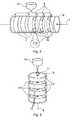
- Figure 3shows a gapped core leg 1 according to one embodiment of the invention with a plurality of core elements 2 being separated by direct cast spacers 3.
- one of the direct cast spacers 3appears to be loose, but this is only for the purpose of illustrating that the whole volume between two core elements 2 is filled with the spacer material.
- the direct cast spacers 3have a strong adhesion with the core elements 2 as a result of the direct casting method.
- all the spacers 3are of the direct cast type, but using other types of spacers in some of the gaps might turn out to be desirable. This could e.g. be because of worsened cooling properties of the core leg 1 when the gaps are completely filled with material. Ceramic spacers 10 and other prior art solutions may be used in some of the gaps when desired.
- the outermost core elements 2 of the core leg 1may be machined after casting in order to bring the dimensions of the core leg 1 within desired tolerances. It is also possible to allow direct cast spacers 3 to be the outermost elements of the core leg 1, especially if this is preferable from the machining point of view.
- FIG. 4shows a direct cast spacer 3 according to one embodiment of the invention.
- the direct cast spacer 3has two main surfaces 7 and a side surface 6.
- the spacer materialis preferably a polymer composite such as polymer concrete.
- the spacer materialcan be reinforced with appropriate material such as glass fibre or carbon fibre.
- the side surface 6 of the direct cast spacers 3is provided with through holes 5 in order to improve the cooling properties.
- the through holes 5are accomplished by, before casting, providing the corresponding gaps between adjacent core elements 2 with tubes or pipes across the gap through a surface corresponding to the side surface 6 of the direct cast spacer 3.
- the tubes or pipesfunction at the same time as reinforcement such that no additional reinforcement is needed.
- the through holes 5are preferably located close to the core elements 2, and they are preferably running in two levels adjacent to each main surface 7 of the direct cast spacer 3.
- a plurality of direct cast spacers 3, preferably all of them,can be cast in one shot.
- Casting in one shotentails an additional advantage of a fast manufacturing cycle.
- Figure 5shows a casting arrangement according to one embodiment of the invention, wherein the mould 8 is provided with an individual radial gate 9 for each gap between adjacent core elements 2 which is to comprise a direct cast spacer 3.
- the castingis done by arranging the core elements 2 in a mould 8 in a stacked manner and filling any predetermined gap between adjacent core elements 2 with the spacer material 13.
- Individual gates 9enable a fast casting cycle and complete filling of the gaps.
- the axis 4 of the core leglies preferably substantially horizontally during casting.
- the distances between the core elements 2may be defined before casting by arranging distance pieces 10 in the gaps between adjacent core elements 2, and by keeping the stack tight during casting by applying an appropriate axial force at the outermost core elements 2. Three distance pieces 10 in each gap ensure a steady support for the core elements 2.
- the distance pieces 10may be manufactured from the same material as the direct cast spacers 3, but they may also consist of other suitable insulating material.
- Figure 6shows a casting arrangement according to another embodiment of the invention, wherein the mould 8 is provided with a common gate 11 for several gaps between adjacent core elements 2.
- the gaps on both sides of a core element 2are connected by providing the dividing core element 2 with a through hole 12. All the gaps of the core leg can be connected by through holes 12 when desired, but some gaps may be isolated in order to use an alternative type of spacer in them.
- the axis 4 of the core legis preferably substantially vertical during casting, and the common gate 11 is placed in an axial end of the mould 8.
- Placing the gate 11 at the top endcan be chosen in order to allow gravity to contribute to filling the gaps, and placing the gate 11 at the bottom end can be chosen in order to enhance the extraction of air, whichever placement turns out to be more advantageous.
- This casting arrangementenables the use of a simple mould 8 with a single gate 11, but the number of gates 11 may be increased when desired. Increasing the number of gates 11 may involve providing both axial ends of the mould 8 with a gate 11, or combining axial gates 11 with radial ones 9.
- Vacuum castingcan be applied if the presence of air bubbles is considered critical. However, small air bubbles are not expected to be a problem since the mechanical strength is ensured by the massive direct cast spacers 3 and small air bubbles do not affect the electrical properties of the spacer.
Landscapes
- Engineering & Computer Science (AREA)
- Power Engineering (AREA)
- Manufacturing & Machinery (AREA)
- Chemical & Material Sciences (AREA)
- Composite Materials (AREA)
- Casting Or Compression Moulding Of Plastics Or The Like (AREA)
- Insulating Of Coils (AREA)
Description
- The present invention relates to a core leg for a shunt reactor, wherein magnetic core elements of the leg are separated by spacers between the core elements. The present invention also relates to manufacturing of a core leg with spacers.
- A shunt reactor is an inductive device which has an important function of compensating capacitive generation in a high voltage power transmission system. In a gapped core type of reactor a subdivided core leg comprising magnetic core elements is provided inside the reactor winding. This core leg functions as a carrier and director of the magnetic flux, thereby enabling high energy density and an advantageous operation of the reactor at higher system voltages.
- A conventional core leg comprises a stack of magnetic core elements separated by spacer elements such as ceramic spacers. The core elements may be in the form of cylindrical segments of laminated core steel sheets, and the material of the spacer elements may be steatite or alumina. Typical spacer elements are cylinder-shaped and fill the core gaps to approximately 50-60%, but also hexagonal spacers have been suggested which fill the core gaps to a greater extent. The spacers may be bonded to the core elements with epoxy to form a rigid core leg.
- The manufacturing of a core leg with a construction as described above requires high precision and a considerable amount of craftsmanship. When the ceramic spacers are bonded onto the core steel cylinder with epoxy, the tops of the spacers are planed to ensure an even surface before stacking the next core element. The machining of the ceramic spacers is difficult and expensive, and assemblage of the core leg segment by segment is very time-consuming. Moreover, the great number of manual manufacturing steps is leading to decreased precision of the construction causing increased sound level of the reactor and deformation of the gaps and core elements during operation. From the sound level point of view, it would also be desirable to increase the rigidity of the core leg.
- One example of a gapped core leg construction is known from
CA1034646 , wherein the use of hard spacer material such as Micarta®, which is a composite of linen or paper fabric in a thermosetting plastic, is suggested. JP58128709 - One object of the invention is thus to provide a gapped core leg for a shunt reactor which is simple to manufacture, and which has improved precision, increased rigidity and reduced sound level compared to known gapped core legs. It is a further object of the invention to provide a simple method for manufacturing a gapped core leg, which method leads to an improved end product.
- These objects are achieved by the device according to
claim 1 and the method according toclaim 6. - According to one embodiment of the invention, there is provided a gapped core leg for a shunt reactor, the gapped core leg comprising: a plurality of core elements arranged in a stacked manner, and a spacer arranged in a gap between adjacent core elements, wherein the spacer is directly cast between the adjacent core elements.
- The invention is based on the realization that by casting the spacers directly between the adjacent core elements a number of earlier manufacturing steps can be avoided, thus resulting in a simplified manufacturing of a gapped core leg while at the same time it becomes easier to keep the manufacturing tolerances. The direct casting method leads to a strong adhesion and a large contact area between the core element and the direct cast spacer, and shows thereby further advantages such as a more rigid construction of the core leg.
- According to one embodiment of the invention, the direct cast spacer comprises a polymer composite. It has been established that by a correct choice of spacer material, not only an improved manufacturing cycle but also increased rigidity and reduced sound level are achieved.
- According to one embodiment of the invention, the polymer composite is a polymer concrete. Polymer concrete has been found to be a preferred material because of its high compressive strength, good adhesion properties, long-term durability in severe heat and severe cold conditions, low permeability to water, good resistance against corrosion and low price.
- According to one embodiment of the invention, the direct cast spacer has two main surfaces and a side surface, the side surface comprising through holes across the direct cast spacer. The worsened cooling properties resulting from completely filling the gap between adjacent core elements with material can be compensated by providing the direct cast spacers with through holes through which a cooling medium may flow.
- According to one embodiment of the invention, the through holes are running in two levels adjacent to each main surface of the direct cast spacer. The heat is generated in the core elements and for effective cooling the through holes should run as close to the heat sources as possible.
- According to the invention, there is provided a method for manufacturing a gapped core leg for a shunt reactor, the method comprising: arranging a plurality of core elements in a mould in a stacked manner, and providing a gap between adjacent core elements with a direct cast spacer by casting spacer material directly between adjacent core elements.
- According to one embodiment of the invention, a plurality of direct cast spacers are cast in one shot. By casting in one shot the manufacture not only becomes faster but also leads to better precision and more uniform end products.
- According to one embodiment of the invention, at least one distance piece is arranged in the gap between adjacent core elements before casting. The at least one distance piece helps to define correct core element distance until the direct cast spacer is cast.
- According to one embodiment of the invention, the number of distance pieces in the gap between adjacent core elements is at least three. With three or more distance pieces a steady support for the individual core elements is provided.
- According to one embodiment of the invention, the mould is provided with an individual radial gate for each gap between adjacent core elements which is to comprise a direct cast spacer. By an individual gate for each gap to be cast, a complete filling of the gap is ensured while enabling a fast casting process.
- According to one embodiment of the invention, the mould is provided with a common gate for several gaps between adjacent core elements, and at least one core element is provided with a through hole to connect the gaps on both sides of the core element. By providing at least one core element with a through hole, it is possible to use a simple mould with a reduced number of gates.
- According to one embodiment of the invention, the gap between adjacent core elements is provided, before casting, with tubes or pipes across the gap through a surface corresponding to a side surface of the direct cast spacer. By this method, through holes crossing a side surface of the direct cast spacer are easily obtained.
- The invention will be explained in greater detail with reference to the accompanying drawings, wherein
- figure 1
- shows a typical prior art shunt reactor core frame with a gapped core leg installed between two yokes and two side legs,
- figure 2
- shows a cylindrical core element of a prior art shunt reactor with ceramic spacers glued on one face of the core element,
- figure 3
- shows a gapped core leg according to one embodiment of the present invention,
- figure 4
- shows a direct cast spacer element according to one embodiment of the invention,
- figure 5
- illustrates a casting arrangement wherein the mould is provided with an individual radial gate for each gap between adjacent core elements, and
- figure 6
- illustrates a casting arrangement wherein the mould is provided with a common gate for several gaps between adjacent core elements.
- In a prior art shunt
reactor core frame 14 offigure 1 , a gappedcore leg 1 is positioned between twoyokes 15 and twoside legs 16. Thecore leg 1 comprises a plurality ofcore elements 2 arranged in a stacked manner. Thecore elements 2 are spaced apart by a large number of cylinder-shapedceramic spacers 17 provided in each gap between adjacentcore elements 2. The magnetic connection between theyokes 15 and thecore leg 1 is obtained via so-calledcross flux plates 18. Thecore elements 2 comprise radial laminatedcore steel sheets 19 according tofigure 2 , the lamination blocks being moulded in epoxy resin to form solid pieces. Theceramic spacers 17 are glued on one face of thecore elements 2 before stacking thecore elements 2. Figure 3 shows a gappedcore leg 1 according to one embodiment of the invention with a plurality ofcore elements 2 being separated bydirect cast spacers 3. Infigure 3 one of thedirect cast spacers 3 appears to be loose, but this is only for the purpose of illustrating that the whole volume between twocore elements 2 is filled with the spacer material. In reality thedirect cast spacers 3 have a strong adhesion with thecore elements 2 as a result of the direct casting method. In one preferred embodiment all thespacers 3 are of the direct cast type, but using other types of spacers in some of the gaps might turn out to be desirable. This could e.g. be because of worsened cooling properties of thecore leg 1 when the gaps are completely filled with material.Ceramic spacers 10 and other prior art solutions may be used in some of the gaps when desired.- The
outermost core elements 2 of thecore leg 1 may be machined after casting in order to bring the dimensions of thecore leg 1 within desired tolerances. It is also possible to allowdirect cast spacers 3 to be the outermost elements of thecore leg 1, especially if this is preferable from the machining point of view. Figure 4 shows adirect cast spacer 3 according to one embodiment of the invention. Thedirect cast spacer 3 has twomain surfaces 7 and aside surface 6. The spacer material is preferably a polymer composite such as polymer concrete. In order to improve the rigidity of thedirect cast spacers 3 and thecore leg 1 as a whole, the spacer material can be reinforced with appropriate material such as glass fibre or carbon fibre. Theside surface 6 of thedirect cast spacers 3 is provided with throughholes 5 in order to improve the cooling properties. The throughholes 5 are accomplished by, before casting, providing the corresponding gaps between adjacentcore elements 2 with tubes or pipes across the gap through a surface corresponding to theside surface 6 of thedirect cast spacer 3. Preferably the tubes or pipes function at the same time as reinforcement such that no additional reinforcement is needed. The throughholes 5 are preferably located close to thecore elements 2, and they are preferably running in two levels adjacent to eachmain surface 7 of thedirect cast spacer 3.- With an appropriate casting arrangement a plurality of
direct cast spacers 3, preferably all of them, can be cast in one shot. This means in practice that the gaps are filled in parallel and no pressure difference between the gaps can occur. This has significance if an excessive pressure is used during the casting which might cause deformation or displacement of thecore elements 2. Casting in one shot entails an additional advantage of a fast manufacturing cycle. Figure 5 shows a casting arrangement according to one embodiment of the invention, wherein the mould 8 is provided with an individualradial gate 9 for each gap between adjacentcore elements 2 which is to comprise adirect cast spacer 3. The casting is done by arranging thecore elements 2 in a mould 8 in a stacked manner and filling any predetermined gap between adjacentcore elements 2 with thespacer material 13.Individual gates 9 enable a fast casting cycle and complete filling of the gaps. In this casting arrangement theaxis 4 of the core leg lies preferably substantially horizontally during casting.- The distances between the
core elements 2 may be defined before casting by arrangingdistance pieces 10 in the gaps between adjacentcore elements 2, and by keeping the stack tight during casting by applying an appropriate axial force at theoutermost core elements 2. Threedistance pieces 10 in each gap ensure a steady support for thecore elements 2. Thedistance pieces 10 may be manufactured from the same material as thedirect cast spacers 3, but they may also consist of other suitable insulating material. Figure 6 shows a casting arrangement according to another embodiment of the invention, wherein the mould 8 is provided with acommon gate 11 for several gaps between adjacentcore elements 2. The gaps on both sides of acore element 2 are connected by providing the dividingcore element 2 with a throughhole 12. All the gaps of the core leg can be connected by throughholes 12 when desired, but some gaps may be isolated in order to use an alternative type of spacer in them. In this casting arrangement theaxis 4 of the core leg is preferably substantially vertical during casting, and thecommon gate 11 is placed in an axial end of the mould 8. Placing thegate 11 at the top end can be chosen in order to allow gravity to contribute to filling the gaps, and placing thegate 11 at the bottom end can be chosen in order to enhance the extraction of air, whichever placement turns out to be more advantageous. This casting arrangement enables the use of a simple mould 8 with asingle gate 11, but the number ofgates 11 may be increased when desired. Increasing the number ofgates 11 may involve providing both axial ends of the mould 8 with agate 11, or combiningaxial gates 11 withradial ones 9.- Vacuum casting can be applied if the presence of air bubbles is considered critical. However, small air bubbles are not expected to be a problem since the mechanical strength is ensured by the massive
direct cast spacers 3 and small air bubbles do not affect the electrical properties of the spacer. - The invention is not limited to the embodiments shown above, but the person skilled in the art may modify them in a plurality of ways within the scope of the invention as defined by the claims. For example, while the drawings only show core legs with a circular cross section, any other suitable cross section shapes are possible without departing from the inventive concept of the invention.
Claims (15)
- A gapped core leg (1) for a shunt reactor, the gapped core leg (1) comprising:a plurality of core elements (2) arranged in a stacked manner, anda spacer (3) arranged in a gap between adjacent core elements (2),characterized in that the spacer (3) is directly cast between the adjacent core elements (2).
- A gapped core leg (1) according to claim 1, wherein the direct cast spacer (3) comprises a polymer composite.
- A gapped core leg (1) according to claim 2, wherein the polymer composite is a polymer concrete.
- A gapped core leg (1) according to any of the preceding claims, wherein the direct cast spacer (3) has two main surfaces (7) and a side surface (6), the side surface (6) comprising through holes (5) across the direct cast spacer (3).
- A gapped core leg according to claim 4, wherein the through holes (5) are running in two levels adjacent to each main surface (7) of the direct cast spacer (3).
- A method for manufacturing a gapped core leg (1) for a shunt reactor, the method comprising:arranging a plurality of core elements (2) in a mould (8) in a stacked manner,providing a gap between adjacent core elements (2) with a direct cast spacer (3) by casting spacer material (13) directly between adjacent core elements (2).
- A method according to claim 6, comprising:casting a plurality of direct cast spacers (3) in one shot.
- A method according to any of the claims 6 and 7, comprising: arranging at least one distance piece (10) in the gap between adjacent core elements (2) before casting.
- A method according to claim 8, wherein the number of distance pieces (10) in the gap between adjacent core elements (2) is at least three.
- A method according to any of the claims 6 to 9, comprising:providing the mould (8) with an individual radial gate (9) for each gap between adjacent core elements (2) which is to comprise a direct cast spacer (3).
- A method according to any of the claims 6 to 9, comprising:providing the mould (8) with a common gate (11) for several gaps between adjacent core elements (2),providing at least one core element with a through hole (12) to connect the gaps on both sides of the core element.
- A method according to any of the claims 6 to 11, comprising:before casting, providing the gap between adjacent core elements (2) with tubes or pipes across the gap through a surface corresponding to a side surface (6) of the direct cast spacer (3).
- A method according to claim 12, comprising:locating the tubes or pipes in two levels adjacent to each adjacent core element (2).
- A method according to any of the claims 6 to 13, wherein the spacer material (13) comprises polymer composite.
- A method according to claim 14, wherein the polymer composite is polymer concrete.
Priority Applications (7)
| Application Number | Priority Date | Filing Date | Title |
|---|---|---|---|
| EP09150901.8AEP2209128B1 (en) | 2009-01-20 | 2009-01-20 | Gapped magnet core |
| CA2749175ACA2749175C (en) | 2009-01-20 | 2009-12-16 | Gapped magnet core |
| PCT/EP2009/067323WO2010083924A1 (en) | 2009-01-20 | 2009-12-16 | Gapped magnet core |
| AU2009337916AAU2009337916B2 (en) | 2009-01-20 | 2009-12-16 | Gapped magnet core |
| CN200980154993.5ACN102282635B (en) | 2009-01-20 | 2009-12-16 | Gapped magnet core |
| ZA2011/04881AZA201104881B (en) | 2009-01-20 | 2011-07-01 | Gapped magnet core |
| US13/187,241US9627118B2 (en) | 2009-01-20 | 2011-07-20 | Gapped magnet core |
Applications Claiming Priority (1)
| Application Number | Priority Date | Filing Date | Title |
|---|---|---|---|
| EP09150901.8AEP2209128B1 (en) | 2009-01-20 | 2009-01-20 | Gapped magnet core |
Publications (2)
| Publication Number | Publication Date |
|---|---|
| EP2209128A1 EP2209128A1 (en) | 2010-07-21 |
| EP2209128B1true EP2209128B1 (en) | 2015-03-04 |
Family
ID=40673319
Family Applications (1)
| Application Number | Title | Priority Date | Filing Date |
|---|---|---|---|
| EP09150901.8AActiveEP2209128B1 (en) | 2009-01-20 | 2009-01-20 | Gapped magnet core |
Country Status (7)
| Country | Link |
|---|---|
| US (1) | US9627118B2 (en) |
| EP (1) | EP2209128B1 (en) |
| CN (1) | CN102282635B (en) |
| AU (1) | AU2009337916B2 (en) |
| CA (1) | CA2749175C (en) |
| WO (1) | WO2010083924A1 (en) |
| ZA (1) | ZA201104881B (en) |
Families Citing this family (10)
| Publication number | Priority date | Publication date | Assignee | Title |
|---|---|---|---|---|
| EP2528069B1 (en)* | 2011-05-26 | 2013-12-18 | Franc Zajc | Multi gap inductor core, multi gap inductor, transformer and corresponding manufacturing method |
| US9287030B2 (en) | 2011-05-26 | 2016-03-15 | Franc Zajc | Multi gap inductor core |
| DE102011116861A1 (en)* | 2011-10-25 | 2013-04-25 | Epcos Ag | Electronic component for guiding a magnetic field |
| US9524820B2 (en)* | 2012-11-13 | 2016-12-20 | Raytheon Company | Apparatus and method for thermal management of magnetic devices |
| US9177708B2 (en)* | 2013-06-14 | 2015-11-03 | Varian Semiconductor Equipment Associates, Inc. | Annular cooling fluid passage for magnets |
| DE102014205560A1 (en)* | 2014-03-26 | 2015-10-01 | SUMIDA Components & Modules GmbH | Plate-shaped scattering body as an insert in the magnetic core of an inductive component, magnetic core with a plate-shaped scattering body and inductive component |
| JP6608762B2 (en)* | 2015-09-17 | 2019-11-20 | Ntn株式会社 | Magnetic element |
| TWI709020B (en)* | 2018-03-30 | 2020-11-01 | 日商京瓷股份有限公司 | Core for inductance, core body for electronic pen, electronic pen and input device |
| DE102021209537A1 (en) | 2021-08-31 | 2023-03-02 | Vitesco Technologies GmbH | transformer |
| DE102023212437A1 (en)* | 2023-12-11 | 2025-06-12 | Zf Friedrichshafen Ag | Throttle device for an electrical circuit for a motor vehicle, power converter, electric axle drive and motor vehicle |
Citations (1)
| Publication number | Priority date | Publication date | Assignee | Title |
|---|---|---|---|---|
| US20060091989A1 (en)* | 2004-11-01 | 2006-05-04 | Patrizio Vinciarelli | Distributed gap magnetic cores |
Family Cites Families (21)
| Publication number | Priority date | Publication date | Assignee | Title |
|---|---|---|---|---|
| US1560934A (en)* | 1923-07-18 | 1925-11-10 | Gen Electric | Alternating-electric-current protective apparatus |
| US2600057A (en)* | 1949-05-18 | 1952-06-10 | Quentin A Kerns | High-voltage multiple core transformer |
| US2599182A (en)* | 1949-06-21 | 1952-06-03 | Atomic Energy Commission | Pulse type transformer |
| US2909742A (en)* | 1953-09-01 | 1959-10-20 | Gen Electric | Machine wound magnetic core |
| CA1034646A (en) | 1975-04-22 | 1978-07-11 | Westinghouse Canada Limited | Gapped core reactor |
| DE2605236C2 (en)* | 1976-02-11 | 1982-12-30 | Eisenwerk-Gesellschaft Maximilianshütte mbH, 8458 Sulzbach-Rosenberg | Use of a piercer and a die to produce a perforated piece |
| GB1571057A (en)* | 1976-01-28 | 1980-07-09 | Sev Marchal | Magnetic circuits |
| DE3012320C2 (en)* | 1980-03-29 | 1985-11-28 | Forschungsinstitut Prof. Dr.-Ing.habil, Dr.phil.nat. Karl Otto Lehmann, Nachf. GmbH & Cie, 7570 Baden-Baden | A method of making a laminated sheet metal core for inductive components and casting molds for use in this method |
| DE3136421A1 (en)* | 1981-09-14 | 1983-03-31 | Transformatoren Union Ag, 7000 Stuttgart | THROTTLE WITH WINDINGS AROUND IRON CORE DISCS |
| JPS58128709A (en) | 1982-01-27 | 1983-08-01 | Fuji Electric Corp Res & Dev Ltd | Spacer for shunt reactor iron core |
| DE3203196A1 (en)* | 1982-01-30 | 1983-08-04 | Messer Griesheim Gmbh, 6000 Frankfurt | Method for connecting an iron core consisting of a plurality of layers |
| US5062197A (en)* | 1988-12-27 | 1991-11-05 | General Electric Company | Dual-permeability core structure for use in high-frequency magnetic components |
| CA2086897A1 (en)* | 1992-01-13 | 1993-07-14 | Howard H. Bobry | Toroidal transformer and method for making |
| FR2740259B1 (en)* | 1995-10-24 | 1997-11-07 | Thomson Csf | MIXED MAGNETIC CORE |
| US6512438B1 (en)* | 1999-12-16 | 2003-01-28 | Honeywell International Inc. | Inductor core-coil assembly and manufacturing thereof |
| CN1388976A (en)* | 2000-08-24 | 2003-01-01 | 皇家菲利浦电子有限公司 | Method of making substantially closed magnetic core, magnetic core and magnetic coil |
| TW563139B (en)* | 2000-11-30 | 2003-11-21 | Nec Tokin Corp | Magnetic core including magnet for magnetic bias and inductor component using the same |
| US6873239B2 (en)* | 2002-11-01 | 2005-03-29 | Metglas Inc. | Bulk laminated amorphous metal inductive device |
| US7317374B2 (en)* | 2003-01-03 | 2008-01-08 | Nucore, Inc. | Self-damped inductor |
| JP2006216650A (en)* | 2005-02-02 | 2006-08-17 | Sumida Corporation | Magnetic element and method of manufacturing magnetic element |
| CN1921271A (en)* | 2005-08-22 | 2007-02-28 | 乐金电子(天津)电器有限公司 | New method for assembling motor stator core |
- 2009
- 2009-01-20EPEP09150901.8Apatent/EP2209128B1/enactiveActive
- 2009-12-16CNCN200980154993.5Apatent/CN102282635B/ennot_activeExpired - Fee Related
- 2009-12-16CACA2749175Apatent/CA2749175C/ennot_activeExpired - Fee Related
- 2009-12-16AUAU2009337916Apatent/AU2009337916B2/ennot_activeCeased
- 2009-12-16WOPCT/EP2009/067323patent/WO2010083924A1/enactiveApplication Filing
- 2011
- 2011-07-01ZAZA2011/04881Apatent/ZA201104881B/enunknown
- 2011-07-20USUS13/187,241patent/US9627118B2/ennot_activeExpired - Fee Related
Patent Citations (1)
| Publication number | Priority date | Publication date | Assignee | Title |
|---|---|---|---|---|
| US20060091989A1 (en)* | 2004-11-01 | 2006-05-04 | Patrizio Vinciarelli | Distributed gap magnetic cores |
Also Published As
| Publication number | Publication date |
|---|---|
| WO2010083924A1 (en) | 2010-07-29 |
| AU2009337916A1 (en) | 2011-07-14 |
| CN102282635B (en) | 2016-08-03 |
| CA2749175A1 (en) | 2010-07-29 |
| EP2209128A1 (en) | 2010-07-21 |
| US9627118B2 (en) | 2017-04-18 |
| ZA201104881B (en) | 2012-03-28 |
| CA2749175C (en) | 2014-12-09 |
| AU2009337916B2 (en) | 2013-09-19 |
| CN102282635A (en) | 2011-12-14 |
| US20110309905A1 (en) | 2011-12-22 |
Similar Documents
| Publication | Publication Date | Title |
|---|---|---|
| EP2209128B1 (en) | Gapped magnet core | |
| CN101300728B (en) | Production method of rotor and rotor | |
| CN102804561A (en) | Rotator core | |
| CN104205571A (en) | Rotor and reluctance motor | |
| CN1247403A (en) | Electric motor and its manufacturing method | |
| CN206595791U (en) | The rotor of motor | |
| CN118369835A (en) | Method for manufacturing rotor of motor | |
| CN102651271A (en) | Amorphous alloy transformer with three-dimensional antitorque clamp and iron core parallel independent distribution structure | |
| CN203149103U (en) | Gradient coil assembly and shimming strip mold | |
| CN106653282B (en) | Coil-adjustable focusing solenoid magnet | |
| CN110808153B (en) | Low-magnetic-leakage air-core reactor | |
| CN205248074U (en) | Reactor iron core stem stem | |
| CN112332570A (en) | Multipolar rotor of outer rotor low-speed synchronous reluctance motor | |
| CN112421902B (en) | High-precision motor rotor core overlapping mold and overlapping forming method of rotor core | |
| CN111341542B (en) | A winding skeleton for magnetic compression device | |
| CN113949223A (en) | Permanent magnet gear speed change device | |
| CN113937979A (en) | Permanent magnet gear speed change device | |
| CN205943685U (en) | Reactor iron core post | |
| CN102709019B (en) | Flexible joint of double-C-shaped detachable magnet coil for realizing irregular arrangement of conductors | |
| RU103229U1 (en) | INDUCTION DEVICE | |
| CN219553377U (en) | Independent coil assembly structure | |
| KR20180000300A (en) | rotator of spoke type motor | |
| CN103085284A (en) | Production technology of component-type plastic composite plate | |
| CN201893222U (en) | Spaced core column of paralleling reactor for oil filling | |
| WO2014189382A1 (en) | Method of encapsulation of stator of electrical machine |
Legal Events
| Date | Code | Title | Description |
|---|---|---|---|
| PUAI | Public reference made under article 153(3) epc to a published international application that has entered the european phase | Free format text:ORIGINAL CODE: 0009012 | |
| 17P | Request for examination filed | Effective date:20090120 | |
| AK | Designated contracting states | Kind code of ref document:A1 Designated state(s):AT BE BG CH CY CZ DE DK EE ES FI FR GB GR HR HU IE IS IT LI LT LU LV MC MK MT NL NO PL PT RO SE SI SK TR | |
| AX | Request for extension of the european patent | Extension state:AL BA RS | |
| AKX | Designation fees paid | Designated state(s):AT BE BG CH CY CZ DE DK EE ES FI FR GB GR HR HU IE IS IT LI LT LU LV MC MK MT NL NO PL PT RO SE SI SK TR | |
| 17Q | First examination report despatched | Effective date:20131219 | |
| REG | Reference to a national code | Ref country code:DE Ref legal event code:R079 Ref document number:602009029715 Country of ref document:DE Free format text:PREVIOUS MAIN CLASS: H01F0003140000 Ipc:H01F0027080000 | |
| GRAP | Despatch of communication of intention to grant a patent | Free format text:ORIGINAL CODE: EPIDOSNIGR1 | |
| RIC1 | Information provided on ipc code assigned before grant | Ipc:H01F 27/08 20060101AFI20140925BHEP Ipc:H01F 41/02 20060101ALI20140925BHEP Ipc:H01F 27/26 20060101ALI20140925BHEP Ipc:H01F 37/00 20060101ALI20140925BHEP Ipc:H01F 3/14 20060101ALI20140925BHEP | |
| INTG | Intention to grant announced | Effective date:20141010 | |
| GRAS | Grant fee paid | Free format text:ORIGINAL CODE: EPIDOSNIGR3 | |
| GRAA | (expected) grant | Free format text:ORIGINAL CODE: 0009210 | |
| AK | Designated contracting states | Kind code of ref document:B1 Designated state(s):AT BE BG CH CY CZ DE DK EE ES FI FR GB GR HR HU IE IS IT LI LT LU LV MC MK MT NL NO PL PT RO SE SI SK TR | |
| REG | Reference to a national code | Ref country code:GB Ref legal event code:FG4D | |
| REG | Reference to a national code | Ref country code:CH Ref legal event code:EP | |
| REG | Reference to a national code | Ref country code:IE Ref legal event code:FG4D | |
| REG | Reference to a national code | Ref country code:AT Ref legal event code:REF Ref document number:714478 Country of ref document:AT Kind code of ref document:T Effective date:20150415 | |
| REG | Reference to a national code | Ref country code:DE Ref legal event code:R096 Ref document number:602009029715 Country of ref document:DE Effective date:20150416 | |
| REG | Reference to a national code | Ref country code:NL Ref legal event code:VDEP Effective date:20150304 | |
| PG25 | Lapsed in a contracting state [announced via postgrant information from national office to epo] | Ref country code:NO Free format text:LAPSE BECAUSE OF FAILURE TO SUBMIT A TRANSLATION OF THE DESCRIPTION OR TO PAY THE FEE WITHIN THE PRESCRIBED TIME-LIMIT Effective date:20150604 Ref country code:SE Free format text:LAPSE BECAUSE OF FAILURE TO SUBMIT A TRANSLATION OF THE DESCRIPTION OR TO PAY THE FEE WITHIN THE PRESCRIBED TIME-LIMIT Effective date:20150304 Ref country code:ES Free format text:LAPSE BECAUSE OF FAILURE TO SUBMIT A TRANSLATION OF THE DESCRIPTION OR TO PAY THE FEE WITHIN THE PRESCRIBED TIME-LIMIT Effective date:20150304 Ref country code:LT Free format text:LAPSE BECAUSE OF FAILURE TO SUBMIT A TRANSLATION OF THE DESCRIPTION OR TO PAY THE FEE WITHIN THE PRESCRIBED TIME-LIMIT Effective date:20150304 Ref country code:HR Free format text:LAPSE BECAUSE OF FAILURE TO SUBMIT A TRANSLATION OF THE DESCRIPTION OR TO PAY THE FEE WITHIN THE PRESCRIBED TIME-LIMIT Effective date:20150304 Ref country code:FI Free format text:LAPSE BECAUSE OF FAILURE TO SUBMIT A TRANSLATION OF THE DESCRIPTION OR TO PAY THE FEE WITHIN THE PRESCRIBED TIME-LIMIT Effective date:20150304 | |
| REG | Reference to a national code | Ref country code:LT Ref legal event code:MG4D | |
| PG25 | Lapsed in a contracting state [announced via postgrant information from national office to epo] | Ref country code:LV Free format text:LAPSE BECAUSE OF FAILURE TO SUBMIT A TRANSLATION OF THE DESCRIPTION OR TO PAY THE FEE WITHIN THE PRESCRIBED TIME-LIMIT Effective date:20150304 Ref country code:GR Free format text:LAPSE BECAUSE OF FAILURE TO SUBMIT A TRANSLATION OF THE DESCRIPTION OR TO PAY THE FEE WITHIN THE PRESCRIBED TIME-LIMIT Effective date:20150605 | |
| PG25 | Lapsed in a contracting state [announced via postgrant information from national office to epo] | Ref country code:NL Free format text:LAPSE BECAUSE OF FAILURE TO SUBMIT A TRANSLATION OF THE DESCRIPTION OR TO PAY THE FEE WITHIN THE PRESCRIBED TIME-LIMIT Effective date:20150304 | |
| PG25 | Lapsed in a contracting state [announced via postgrant information from national office to epo] | Ref country code:EE Free format text:LAPSE BECAUSE OF FAILURE TO SUBMIT A TRANSLATION OF THE DESCRIPTION OR TO PAY THE FEE WITHIN THE PRESCRIBED TIME-LIMIT Effective date:20150304 Ref country code:CZ Free format text:LAPSE BECAUSE OF FAILURE TO SUBMIT A TRANSLATION OF THE DESCRIPTION OR TO PAY THE FEE WITHIN THE PRESCRIBED TIME-LIMIT Effective date:20150304 Ref country code:PT Free format text:LAPSE BECAUSE OF FAILURE TO SUBMIT A TRANSLATION OF THE DESCRIPTION OR TO PAY THE FEE WITHIN THE PRESCRIBED TIME-LIMIT Effective date:20150706 Ref country code:SK Free format text:LAPSE BECAUSE OF FAILURE TO SUBMIT A TRANSLATION OF THE DESCRIPTION OR TO PAY THE FEE WITHIN THE PRESCRIBED TIME-LIMIT Effective date:20150304 Ref country code:RO Free format text:LAPSE BECAUSE OF FAILURE TO SUBMIT A TRANSLATION OF THE DESCRIPTION OR TO PAY THE FEE WITHIN THE PRESCRIBED TIME-LIMIT Effective date:20150304 | |
| PG25 | Lapsed in a contracting state [announced via postgrant information from national office to epo] | Ref country code:PL Free format text:LAPSE BECAUSE OF FAILURE TO SUBMIT A TRANSLATION OF THE DESCRIPTION OR TO PAY THE FEE WITHIN THE PRESCRIBED TIME-LIMIT Effective date:20150304 Ref country code:IS Free format text:LAPSE BECAUSE OF FAILURE TO SUBMIT A TRANSLATION OF THE DESCRIPTION OR TO PAY THE FEE WITHIN THE PRESCRIBED TIME-LIMIT Effective date:20150704 | |
| REG | Reference to a national code | Ref country code:DE Ref legal event code:R097 Ref document number:602009029715 Country of ref document:DE | |
| PG25 | Lapsed in a contracting state [announced via postgrant information from national office to epo] | Ref country code:IT Free format text:LAPSE BECAUSE OF FAILURE TO SUBMIT A TRANSLATION OF THE DESCRIPTION OR TO PAY THE FEE WITHIN THE PRESCRIBED TIME-LIMIT Effective date:20150304 | |
| PLBE | No opposition filed within time limit | Free format text:ORIGINAL CODE: 0009261 | |
| STAA | Information on the status of an ep patent application or granted ep patent | Free format text:STATUS: NO OPPOSITION FILED WITHIN TIME LIMIT | |
| PG25 | Lapsed in a contracting state [announced via postgrant information from national office to epo] | Ref country code:DK Free format text:LAPSE BECAUSE OF FAILURE TO SUBMIT A TRANSLATION OF THE DESCRIPTION OR TO PAY THE FEE WITHIN THE PRESCRIBED TIME-LIMIT Effective date:20150304 | |
| 26N | No opposition filed | Effective date:20151207 | |
| PG25 | Lapsed in a contracting state [announced via postgrant information from national office to epo] | Ref country code:SI Free format text:LAPSE BECAUSE OF FAILURE TO SUBMIT A TRANSLATION OF THE DESCRIPTION OR TO PAY THE FEE WITHIN THE PRESCRIBED TIME-LIMIT Effective date:20150304 | |
| PG25 | Lapsed in a contracting state [announced via postgrant information from national office to epo] | Ref country code:BE Free format text:LAPSE BECAUSE OF NON-PAYMENT OF DUE FEES Effective date:20160131 | |
| PG25 | Lapsed in a contracting state [announced via postgrant information from national office to epo] | Ref country code:LU Free format text:LAPSE BECAUSE OF FAILURE TO SUBMIT A TRANSLATION OF THE DESCRIPTION OR TO PAY THE FEE WITHIN THE PRESCRIBED TIME-LIMIT Effective date:20160120 Ref country code:BE Free format text:LAPSE BECAUSE OF FAILURE TO SUBMIT A TRANSLATION OF THE DESCRIPTION OR TO PAY THE FEE WITHIN THE PRESCRIBED TIME-LIMIT Effective date:20150304 | |
| REG | Reference to a national code | Ref country code:CH Ref legal event code:PL | |
| GBPC | Gb: european patent ceased through non-payment of renewal fee | Effective date:20160120 | |
| PG25 | Lapsed in a contracting state [announced via postgrant information from national office to epo] | Ref country code:MC Free format text:LAPSE BECAUSE OF FAILURE TO SUBMIT A TRANSLATION OF THE DESCRIPTION OR TO PAY THE FEE WITHIN THE PRESCRIBED TIME-LIMIT Effective date:20150304 | |
| REG | Reference to a national code | Ref country code:AT Ref legal event code:UEP Ref document number:714478 Country of ref document:AT Kind code of ref document:T Effective date:20150304 | |
| REG | Reference to a national code | Ref country code:FR Ref legal event code:ST Effective date:20160930 | |
| PG25 | Lapsed in a contracting state [announced via postgrant information from national office to epo] | Ref country code:GB Free format text:LAPSE BECAUSE OF NON-PAYMENT OF DUE FEES Effective date:20160120 Ref country code:LI Free format text:LAPSE BECAUSE OF NON-PAYMENT OF DUE FEES Effective date:20160131 Ref country code:CH Free format text:LAPSE BECAUSE OF NON-PAYMENT OF DUE FEES Effective date:20160131 | |
| REG | Reference to a national code | Ref country code:IE Ref legal event code:MM4A | |
| PG25 | Lapsed in a contracting state [announced via postgrant information from national office to epo] | Ref country code:FR Free format text:LAPSE BECAUSE OF NON-PAYMENT OF DUE FEES Effective date:20160201 | |
| PG25 | Lapsed in a contracting state [announced via postgrant information from national office to epo] | Ref country code:IE Free format text:LAPSE BECAUSE OF NON-PAYMENT OF DUE FEES Effective date:20160120 | |
| PGFP | Annual fee paid to national office [announced via postgrant information from national office to epo] | Ref country code:AT Payment date:20170123 Year of fee payment:9 | |
| PGFP | Annual fee paid to national office [announced via postgrant information from national office to epo] | Ref country code:TR Payment date:20170111 Year of fee payment:9 | |
| PG25 | Lapsed in a contracting state [announced via postgrant information from national office to epo] | Ref country code:MT Free format text:LAPSE BECAUSE OF FAILURE TO SUBMIT A TRANSLATION OF THE DESCRIPTION OR TO PAY THE FEE WITHIN THE PRESCRIBED TIME-LIMIT Effective date:20150304 | |
| PG25 | Lapsed in a contracting state [announced via postgrant information from national office to epo] | Ref country code:CY Free format text:LAPSE BECAUSE OF FAILURE TO SUBMIT A TRANSLATION OF THE DESCRIPTION OR TO PAY THE FEE WITHIN THE PRESCRIBED TIME-LIMIT Effective date:20150304 Ref country code:HU Free format text:LAPSE BECAUSE OF FAILURE TO SUBMIT A TRANSLATION OF THE DESCRIPTION OR TO PAY THE FEE WITHIN THE PRESCRIBED TIME-LIMIT; INVALID AB INITIO Effective date:20090120 | |
| PG25 | Lapsed in a contracting state [announced via postgrant information from national office to epo] | Ref country code:MT Free format text:LAPSE BECAUSE OF FAILURE TO SUBMIT A TRANSLATION OF THE DESCRIPTION OR TO PAY THE FEE WITHIN THE PRESCRIBED TIME-LIMIT Effective date:20160131 Ref country code:MK Free format text:LAPSE BECAUSE OF FAILURE TO SUBMIT A TRANSLATION OF THE DESCRIPTION OR TO PAY THE FEE WITHIN THE PRESCRIBED TIME-LIMIT Effective date:20150304 | |
| PG25 | Lapsed in a contracting state [announced via postgrant information from national office to epo] | Ref country code:BG Free format text:LAPSE BECAUSE OF FAILURE TO SUBMIT A TRANSLATION OF THE DESCRIPTION OR TO PAY THE FEE WITHIN THE PRESCRIBED TIME-LIMIT Effective date:20150304 | |
| REG | Reference to a national code | Ref country code:AT Ref legal event code:MM01 Ref document number:714478 Country of ref document:AT Kind code of ref document:T Effective date:20180120 | |
| PG25 | Lapsed in a contracting state [announced via postgrant information from national office to epo] | Ref country code:AT Free format text:LAPSE BECAUSE OF NON-PAYMENT OF DUE FEES Effective date:20180120 | |
| REG | Reference to a national code | Ref country code:DE Ref legal event code:R081 Ref document number:602009029715 Country of ref document:DE Owner name:HITACHI ENERGY SWITZERLAND AG, CH Free format text:FORMER OWNER: ABB RESEARCH LTD., ZUERICH, CH Ref country code:DE Ref legal event code:R081 Ref document number:602009029715 Country of ref document:DE Owner name:ABB SCHWEIZ AG, CH Free format text:FORMER OWNER: ABB RESEARCH LTD., ZUERICH, CH Ref country code:DE Ref legal event code:R081 Ref document number:602009029715 Country of ref document:DE Owner name:ABB POWER GRIDS SWITZERLAND AG, CH Free format text:FORMER OWNER: ABB RESEARCH LTD., ZUERICH, CH | |
| REG | Reference to a national code | Ref country code:DE Ref legal event code:R081 Ref document number:602009029715 Country of ref document:DE Owner name:HITACHI ENERGY SWITZERLAND AG, CH Free format text:FORMER OWNER: ABB SCHWEIZ AG, BADEN, CH Ref country code:DE Ref legal event code:R081 Ref document number:602009029715 Country of ref document:DE Owner name:HITACHI ENERGY LTD, CH Free format text:FORMER OWNER: ABB SCHWEIZ AG, BADEN, CH Ref country code:DE Ref legal event code:R081 Ref document number:602009029715 Country of ref document:DE Owner name:ABB POWER GRIDS SWITZERLAND AG, CH Free format text:FORMER OWNER: ABB SCHWEIZ AG, BADEN, CH | |
| REG | Reference to a national code | Ref country code:DE Ref legal event code:R081 Ref document number:602009029715 Country of ref document:DE Owner name:HITACHI ENERGY SWITZERLAND AG, CH Free format text:FORMER OWNER: ABB POWER GRIDS SWITZERLAND AG, BADEN, CH Ref country code:DE Ref legal event code:R081 Ref document number:602009029715 Country of ref document:DE Owner name:HITACHI ENERGY LTD, CH Free format text:FORMER OWNER: ABB POWER GRIDS SWITZERLAND AG, BADEN, CH | |
| PG25 | Lapsed in a contracting state [announced via postgrant information from national office to epo] | Ref country code:TR Free format text:LAPSE BECAUSE OF NON-PAYMENT OF DUE FEES Effective date:20180120 | |
| P01 | Opt-out of the competence of the unified patent court (upc) registered | Effective date:20230527 | |
| REG | Reference to a national code | Ref country code:DE Ref legal event code:R082 Ref document number:602009029715 Country of ref document:DE Representative=s name:DENNEMEYER & ASSOCIATES RECHTSANWALTSGESELLSCH, DE Ref country code:DE Ref legal event code:R082 Ref document number:602009029715 Country of ref document:DE Representative=s name:DENNEMEYER & ASSOCIATES S.A., DE Ref country code:DE Ref legal event code:R081 Ref document number:602009029715 Country of ref document:DE Owner name:HITACHI ENERGY LTD, CH Free format text:FORMER OWNER: HITACHI ENERGY SWITZERLAND AG, BADEN, CH | |
| PGFP | Annual fee paid to national office [announced via postgrant information from national office to epo] | Ref country code:DE Payment date:20250121 Year of fee payment:17 | |
| REG | Reference to a national code | Ref country code:DE Ref legal event code:R082 Ref document number:602009029715 Country of ref document:DE Representative=s name:DENNEMEYER & ASSOCIATES RECHTSANWALTSGESELLSCH, DE |