EP2208473B1 - Improved polyaxial screwdriver for a pedicle screw system - Google Patents
Improved polyaxial screwdriver for a pedicle screw systemDownload PDFInfo
- Publication number
- EP2208473B1 EP2208473B1EP10162029.2AEP10162029AEP2208473B1EP 2208473 B1EP2208473 B1EP 2208473B1EP 10162029 AEP10162029 AEP 10162029AEP 2208473 B1EP2208473 B1EP 2208473B1
- Authority
- EP
- European Patent Office
- Prior art keywords
- polyaxial
- screw
- screwdriver
- ratchet
- cylindrical
- Prior art date
- Legal status (The legal status is an assumption and is not a legal conclusion. Google has not performed a legal analysis and makes no representation as to the accuracy of the status listed.)
- Not-in-force
Links
Images


Classifications
- A—HUMAN NECESSITIES
- A61—MEDICAL OR VETERINARY SCIENCE; HYGIENE
- A61B—DIAGNOSIS; SURGERY; IDENTIFICATION
- A61B17/00—Surgical instruments, devices or methods
- A61B17/56—Surgical instruments or methods for treatment of bones or joints; Devices specially adapted therefor
- A61B17/58—Surgical instruments or methods for treatment of bones or joints; Devices specially adapted therefor for osteosynthesis, e.g. bone plates, screws or setting implements
- A61B17/68—Internal fixation devices, including fasteners and spinal fixators, even if a part thereof projects from the skin
- A61B17/70—Spinal positioners or stabilisers, e.g. stabilisers comprising fluid filler in an implant
- A61B17/7074—Tools specially adapted for spinal fixation operations other than for bone removal or filler handling
- A61B17/7076—Tools specially adapted for spinal fixation operations other than for bone removal or filler handling for driving, positioning or assembling spinal clamps or bone anchors specially adapted for spinal fixation
- A61B17/7082—Tools specially adapted for spinal fixation operations other than for bone removal or filler handling for driving, positioning or assembling spinal clamps or bone anchors specially adapted for spinal fixation for driving, i.e. rotating, screws or screw parts specially adapted for spinal fixation, e.g. for driving polyaxial or tulip-headed screws
- A—HUMAN NECESSITIES
- A61—MEDICAL OR VETERINARY SCIENCE; HYGIENE
- A61B—DIAGNOSIS; SURGERY; IDENTIFICATION
- A61B17/00—Surgical instruments, devices or methods
- A61B17/56—Surgical instruments or methods for treatment of bones or joints; Devices specially adapted therefor
- A61B17/58—Surgical instruments or methods for treatment of bones or joints; Devices specially adapted therefor for osteosynthesis, e.g. bone plates, screws or setting implements
- A61B17/68—Internal fixation devices, including fasteners and spinal fixators, even if a part thereof projects from the skin
- A61B17/70—Spinal positioners or stabilisers, e.g. stabilisers comprising fluid filler in an implant
- A61B17/7001—Screws or hooks combined with longitudinal elements which do not contact vertebrae
- A61B17/7032—Screws or hooks with U-shaped head or back through which longitudinal rods pass
- A—HUMAN NECESSITIES
- A61—MEDICAL OR VETERINARY SCIENCE; HYGIENE
- A61B—DIAGNOSIS; SURGERY; IDENTIFICATION
- A61B17/00—Surgical instruments, devices or methods
- A61B17/56—Surgical instruments or methods for treatment of bones or joints; Devices specially adapted therefor
- A61B17/58—Surgical instruments or methods for treatment of bones or joints; Devices specially adapted therefor for osteosynthesis, e.g. bone plates, screws or setting implements
- A61B17/68—Internal fixation devices, including fasteners and spinal fixators, even if a part thereof projects from the skin
- A61B17/70—Spinal positioners or stabilisers, e.g. stabilisers comprising fluid filler in an implant
- A61B17/7001—Screws or hooks combined with longitudinal elements which do not contact vertebrae
- A61B17/7035—Screws or hooks, wherein a rod-clamping part and a bone-anchoring part can pivot relative to each other
- A61B17/7037—Screws or hooks, wherein a rod-clamping part and a bone-anchoring part can pivot relative to each other wherein pivoting is blocked when the rod is clamped
- A—HUMAN NECESSITIES
- A61—MEDICAL OR VETERINARY SCIENCE; HYGIENE
- A61B—DIAGNOSIS; SURGERY; IDENTIFICATION
- A61B17/00—Surgical instruments, devices or methods
- A61B17/56—Surgical instruments or methods for treatment of bones or joints; Devices specially adapted therefor
- A61B17/58—Surgical instruments or methods for treatment of bones or joints; Devices specially adapted therefor for osteosynthesis, e.g. bone plates, screws or setting implements
- A61B17/68—Internal fixation devices, including fasteners and spinal fixators, even if a part thereof projects from the skin
- A61B17/84—Fasteners therefor or fasteners being internal fixation devices
- A61B17/86—Pins or screws or threaded wires; nuts therefor
- A61B17/8605—Heads, i.e. proximal ends projecting from bone
- A—HUMAN NECESSITIES
- A61—MEDICAL OR VETERINARY SCIENCE; HYGIENE
- A61B—DIAGNOSIS; SURGERY; IDENTIFICATION
- A61B17/00—Surgical instruments, devices or methods
- A61B17/56—Surgical instruments or methods for treatment of bones or joints; Devices specially adapted therefor
- A61B17/58—Surgical instruments or methods for treatment of bones or joints; Devices specially adapted therefor for osteosynthesis, e.g. bone plates, screws or setting implements
- A61B17/88—Osteosynthesis instruments; Methods or means for implanting or extracting internal or external fixation devices
- A61B17/8875—Screwdrivers, spanners or wrenches
- A61B17/8886—Screwdrivers, spanners or wrenches holding the screw head
- A61B17/8888—Screwdrivers, spanners or wrenches holding the screw head at its central region
- A—HUMAN NECESSITIES
- A61—MEDICAL OR VETERINARY SCIENCE; HYGIENE
- A61B—DIAGNOSIS; SURGERY; IDENTIFICATION
- A61B17/00—Surgical instruments, devices or methods
- A61B17/56—Surgical instruments or methods for treatment of bones or joints; Devices specially adapted therefor
- A61B2017/564—Methods for bone or joint treatment
Definitions
- the present inventionrelates generally to spinal fixation devices and more specifically relates to a pedicle screw system having an improved screwdriver coupling interface and securing of the screwdriver to the polyaxial screw assembly.
- the spinal columnis a highly complex system of bones and connective tissues that provides support for the body and protects the delicate spinal cord and nerves.
- spinal column disordersincluding scoliosis (abnormal lateral curvature of the spine), kyphosis (abnormal forward curvature of the spine, usually in the thoracic spine), excess lordosis (abnormal backward curvature of the spine, usually in the lumbar spine), spondylolisthesis (forward displacement of one vertebra over another, usually in a lumbar or cervical spine) and other disorders caused by abnormalities, disease or trauma, such as ruptured or slipped discs, degenerative disc disease, fractured vertebra, and the like. Patients that suffer from such conditions usually experience extreme and debilitating pain, as well as diminished nerve function.
- spinal fixationA technique commonly referred to as spinal fixation is employed for fusing together and/or mechanically immobilizing vertebrae of the spine.
- Spinal fixationmay also be used to alter the alignment of adjacent vertebrae relative to one another so as to change the overall alignment of the spine.
- Such techniqueshave been used effectively to treat the above-described conditions and, in most cases, to relieve pain suffered by the patient.
- Spinal fixationoften involves use of polyaxial pedicle screws fixed to the vertebrae.
- the present inventionprovides a pedicle screw system as defined in claim 1. Further embodiments of the invention are defined in the dependent claims.
- FIG 1shows a polyaxial screwdriver 20.
- the polyaxial screwdriver 20has a handle 22 and a screw engaging end 24.
- the screw engaging end 24engages the head of a polyaxial screw such that when the screwdriver 20 is rotated via the handle 22, the polyaxial screw is advanced or retracted in the vertebra.
- the polyaxial screwdriver 20has an internal shaft 21 ( Figure 2A ) that connects to the handle 22 and has a screw engaging end 24 ( Figure 3 ) formed on the end opposite the handle 22.
- An outside sleeve 23is slidably inserted over the internal shaft 21.
- the screw engaging end 24has a hollow cylindrical portion 26.
- the hollow cylindrical portion 26has a cylindrical external surface 28.
- the internal surface of the hollow cylindrical portion 26has semi-cylindrical cutouts 30 that are spaced at a distance from each other. Placed between the semi-cylindrical cutouts 30 are cylindrical structures 32.
- the cylindrical structures 32project beyond the edge of the semi-cylindrical cutouts 30 and towards the center of the hollow cylindrical portion 26.
- the semi-cylindrical cutouts 30 and the cylindrical structures 32alternate around the internal periphery of the cylindrical end 26. There may be, for example, eight semi-cylindrical cutouts 30 and eight cylindrical structures 32.
- any appropriate number of the semi-cylindrical cutouts 30 and the cylindrical structures 32may be used.
- the cutoutscan be of spherical, conical, rectilinear or any other suitable shape.
- the cylindrical structures 32can alternatively be of spherical, conical, rectilinear or any other suitable shape.
- the external surface of the screw engaging end 24has two lateral projections 34 located diametrically opposite each other. Alternative examples may not include the two lateral projections 34.
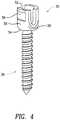
- FIG 4shows a polyaxial bone screw assembly 35 having a bone screw 36.
- the polyaxial bone screw 36has threads 38 and a head 40( Figure 5 ).
- the threads 38terminate at a neck 42 located between the threads 38 and the head 40.
- the neck 42has a concave surface having a diameter that is less than the diameter of the threads 38.
- the reduced diameter neck 42allows the screw 36 to pivot and rotate through a broader range of motion.
- the screwincluding the external threads 38, neck 42 and head 40, is preferably made of a non-organic material that is durable and that can be implanted in a human body, such as titanium or stainless steel.
- Commonly assigned U.S. Patents 6,488,681 and 6,554,834disclose polyaxial bone screw of various designs. Any of the bone screws described in the '681 patent or the '834 patent may be adapted for use with the present screwdriver that has been appropriately modified.
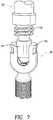
- Polyaxial bone screw assembly 35also includes a coupling element 50 (also known as a tulip; Figure 6 ) for coupling an orthopedic stabilizing rod with the polyaxial screw assembly 35.
- Coupling element 50is preferably made of an inert material such as titanium or stainless steel.
- Coupling element 50has an upper end 52 and a lower end 54.
- Coupling element 50also preferably has an outer surface 56 including a convex surface at the lower end 54 thereof and a cylindrical surface at the upper end thereof.
- Outer surface 56also preferably includes one or more grooves 58 formed therein so that coupling element 50 may be grasped using a tool.
- the coupling element 50has a bore for receiving the screw 36.
- the boredefines an inner surface of coupling element 50 and has internal threads 60 at the inner surface of the upper end 52 of the coupling element 50.
- the lower end of the borepreferably has a shape adapted to accommodate head 40.
- the threads on the coupling elementmay be external threads.
- the head 40 of the screw 36sits at the bottom of the coupling element 50.
- the head 40includes a flat surface 44.
- the head 40has a spherical surface 45 that is located below the flat surface 44.
- a cylindrical wall 46is formed on the flat surface 44.
- Solid cylinders 48are formed on the outside surface of the cylindrical wall 46.
- the solid cylinders 48are equidistant from their neighboring solid cylinders 48.
- the solid cylinders 48are located on the head 40 such that they can align with the semi-cylindrical cutouts 30 when the screw engaging end 24 is placed on top of the head 40.
- the solid cylindersare sized so that they will slide snugly in the semi-cylindrical cutouts 30 when the screw engaging end 24 is lowered on the head 40.
- the screw engaging end 24when the screw engaging end 24 is lowered on the head 40, the cylindrical structures 32 slide in the region between the solid cylinders 48.
- the screw engaging end 24is lowered on the head 40, it is possible that there is slight misalignment between the solid cylinders 48 and the semi-cylindrical cutouts 30.
- the edges of the semi-cylindrical cutouts 30will touch the top of the solid cylinders 48. Since the top of the solid cylinders 48 are sloping down the semi-cylindrical cutouts would slide on top of the solid cylinders 48 and thereby self-align.
- the shape and size of the solid cylinders 48 and cylindrical wall 46are complimentary to the shape and size of the semi-cylindrical cutouts 30 and cylindrical structures 32, respectively.
- the solid cylinders 48will also be replaced by spherical structures that are complimentary with the shape and size of the spherical cutouts.
- shapes other than the sphericalmay also be used.
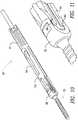
- FIG 7shows the screwdriver 20 being inserted in the polyaxial bone screw assembly 35.
- the screw engaging end 24is shown inserted in the coupling element 50.
- threads 70would align with threads 60 ( Figure 6 ).
- Rotation of handle 22would rotate shaft 21 along with threads 70.
- Such rotationwhen the screw engaging end 24 is engaged with the screw head 40, results in advancing the screw 36 in the bone and engaging together threads 70 and 60.
- the precise mating of the screw engaging end 24 and head 40 along with the engagement of threads 60 and 70results in secure attachment of the screwdriver to the screw.
- FIG. 2Ashows an improved locking mechanism 72.
- the locking mechanism 72includes a ratchet 74 that is attached to the sleeve 23 via a key 76 that is inserted in the sleeve 23 and the ratchet 74.
- the ratchet 74has a button 75 that is integral with ratchet 74 and projects from the surface of the sleeve 23.
- the ratchet 74is in engagement with gear teeth 77 formed on the outside of internal shaft 21 in the region corresponding to the location of the ratchet 74.
- a spring 78applies a force to the ratchet to keep it in engagement with the gear teeth 76.
- Figures 8-9show another polyaxial screwdriver 80 engaged with the polyaxial bone screw assembly 35.
- the construction of the polyaxial screwdriver 80is similar to the polyaxial screwdriver 20 in many respects. Therefore, only the features of the polyaxial screwdriver 80 that are different from the polyaxial screwdriver 20 are described hearafter. Same reference numeral denotes parts that are similar across various examples .
- the outer sleeve 82 of the polyaxial screwdriver 80has a collet 84 formed at the end that is near the screw engaging end 24. Projections (not seen in figures) are formed on the internal surface of the collet 84.
- the end of the sleeve 82 that is closer to the handle 22has external threads 86 formed on it.
- a nut 88is next to the threads 86.
- the nut 88has internal threads that are adapted to threadably engage threads 86.
- the nut 88is in contact with a shoulder formed on shaft 21 such that it is prevented from sliding towards the collet 84.
- FIGS 10-11show yet another polyaxial screwdriver 90 engaged with the polyaxial bone screw assembly 35.
- the construction of the polyaxial screwdriver 90is similar to the polyaxial screwdriver 20 in many respects. Therefore, only the features of the polyaxial screwdriver 90 that are different from the polyaxial screwdriver 20 are described hearafter. Same reference numeral denotes parts that are similar across various examples .
- the outer sleeve 91 of the polyaxial screwdriver 90has a split end.
- the end that engages the coupling element 92is split to form two flexible arms 94.
- the ends of the flexible arms 94 that engages the coupling element 92have a step 96 formed thereon. Steps 98 of complimentary shape are formed on the internal surface of the coupling element 92.
- the steps 98replace the internal threads of the element of figure 6 .
- An internal spring(not seen in the figures 10-11 ) pulls the sleeve 91 tight with respect to the polyaxial bone screw assembly 35 thereby keeping the flexible arms 94 engaged with the coupling element 92.
- a short ring ( Figure 12 )100is located around the outer sleeve 91. The short ring 100 when pulled towards the handle 22 would engage ramps 102 formed on the external surfaces of the arms 94 thereby deflecting arms 91 towards the center of the sleeve 91 and allowing them to disengage from the coupling element 92.
- the polyaxial screwdriver of any one of the above described examplesis lowered on the polyaxial bone screw assembly 35.
- the screw engaging end 24contacts the head 40 of the screw 36, and the screwdriver is lowered further the relative position of the engagement features on the screw engaging end 24 and the head 40 are automatically adjusted to allow smooth engagement of the screw engaging end 24 with the head 40. Additionally, the engagement between the screw engaging end 24 and the head 40 is made secure by any one of the various methods described above.
Landscapes
- Health & Medical Sciences (AREA)
- Orthopedic Medicine & Surgery (AREA)
- Neurology (AREA)
- Life Sciences & Earth Sciences (AREA)
- Surgery (AREA)
- Heart & Thoracic Surgery (AREA)
- Engineering & Computer Science (AREA)
- Biomedical Technology (AREA)
- Nuclear Medicine, Radiotherapy & Molecular Imaging (AREA)
- Medical Informatics (AREA)
- Molecular Biology (AREA)
- Animal Behavior & Ethology (AREA)
- General Health & Medical Sciences (AREA)
- Public Health (AREA)
- Veterinary Medicine (AREA)
- Surgical Instruments (AREA)
Description
- The present invention relates generally to spinal fixation devices and more specifically relates to a pedicle screw system having an improved screwdriver coupling interface and securing of the screwdriver to the polyaxial screw assembly.
- The spinal column is a highly complex system of bones and connective tissues that provides support for the body and protects the delicate spinal cord and nerves. There are many types of spinal column disorders including scoliosis (abnormal lateral curvature of the spine), kyphosis (abnormal forward curvature of the spine, usually in the thoracic spine), excess lordosis (abnormal backward curvature of the spine, usually in the lumbar spine), spondylolisthesis (forward displacement of one vertebra over another, usually in a lumbar or cervical spine) and other disorders caused by abnormalities, disease or trauma, such as ruptured or slipped discs, degenerative disc disease, fractured vertebra, and the like. Patients that suffer from such conditions usually experience extreme and debilitating pain, as well as diminished nerve function.
- A technique commonly referred to as spinal fixation is employed for fusing together and/or mechanically immobilizing vertebrae of the spine. Spinal fixation may also be used to alter the alignment of adjacent vertebrae relative to one another so as to change the overall alignment of the spine. Such techniques have been used effectively to treat the above-described conditions and, in most cases, to relieve pain suffered by the patient. Spinal fixation often involves use of polyaxial pedicle screws fixed to the vertebrae. However, there are some disadvantages associated with current pedicle screws and polyaxial screwdrivers used to install them. There remains room for improvement in the manner of engaging the screw head, the complexity of use, the required manipulation of the many parts associated with some complex devices and improved screw loading during installation.
- Documents
US 2004/138662 ,US 2006/111712 andEP 1 222 899 disclose a pedicle screw system according to the preamble of claim 1. - The present invention provides a pedicle screw system as defined in claim 1. Further embodiments of the invention are defined in the dependent claims.
Figure 1 is a perspective view of a polyaxial screwdriver.Figure 2 is a perspective view of another polyaxial screwdriver.Figure 2A is a cross-sectional perspective view of the polyaxial screwdriver offigure 2 .Figure 3 is a perspective view of the screw engaging end of the polyaxial screwdriver offigure 2 .Figure 4 is a perspective view of a polyaxial bone screw assembly.Figure 5 is a perspective view of the head portion of the polyaxial bone screw offigure 4 .Figure 6 is a perspective view of a coupling element used with the polyaxial bone screw assembly offigure 4 .Figure 7 is a perspective view of polyaxial screwdriver inserted in the polyaxial bone screw assembly offigure 4 .Figure 8 is a perspective view of another polyaxial screwdriver engaged with the polyaxial bone screw assembly offigure 4 .Figure 9 is a enlarged view of the collet section of the polyaxial screwdriver offigure 8 .Figure 10 is a perspective view of another polyaxial screwdriver engaged with the polyaxial bone screw assembly offigure 4 .Figure 11 is a enlarged view of the section of the polyaxial screwdriver offigure 10 that is engaged with the polyaxial bone screw assembly.Figure 12 is a partial cross-sectional view of the polyaxial screwdriver offigure 10 showing a ramp formed on the sleeve and a ring mounted on the sleeve.Figure 1 shows apolyaxial screwdriver 20. Thepolyaxial screwdriver 20 has ahandle 22 and ascrew engaging end 24. Thescrew engaging end 24 engages the head of a polyaxial screw such that when thescrewdriver 20 is rotated via thehandle 22, the polyaxial screw is advanced or retracted in the vertebra. Thepolyaxial screwdriver 20 has an internal shaft 21 (Figure 2A ) that connects to thehandle 22 and has a screw engaging end 24 (Figure 3 ) formed on the end opposite thehandle 22. Anoutside sleeve 23 is slidably inserted over theinternal shaft 21.- The
screw engaging end 24 has a hollowcylindrical portion 26. The hollowcylindrical portion 26 has a cylindricalexternal surface 28. The internal surface of the hollowcylindrical portion 26 hassemi-cylindrical cutouts 30 that are spaced at a distance from each other. Placed between thesemi-cylindrical cutouts 30 arecylindrical structures 32. Thecylindrical structures 32 project beyond the edge of thesemi-cylindrical cutouts 30 and towards the center of the hollowcylindrical portion 26. Thus, thesemi-cylindrical cutouts 30 and thecylindrical structures 32 alternate around the internal periphery of thecylindrical end 26. There may be, for example, eightsemi-cylindrical cutouts 30 and eightcylindrical structures 32. Any appropriate number of thesemi-cylindrical cutouts 30 and thecylindrical structures 32 may be used. For example, the there could be between two and twenty of each of thesemi-cylindrical cutouts 30 and thecylindrical structures 32. Alternatively, the cutouts can be of spherical, conical, rectilinear or any other suitable shape. Similarly, thecylindrical structures 32 can alternatively be of spherical, conical, rectilinear or any other suitable shape. The external surface of thescrew engaging end 24 has twolateral projections 34 located diametrically opposite each other. Alternative examples may not include the twolateral projections 34. Figure 4 shows a polyaxialbone screw assembly 35 having abone screw 36. Thepolyaxial bone screw 36 has threads 38 and a head 40(Figure 5 ). The threads 38 terminate at aneck 42 located between the threads 38 and thehead 40. Theneck 42 has a concave surface having a diameter that is less than the diameter of the threads 38. The reduceddiameter neck 42 allows thescrew 36 to pivot and rotate through a broader range of motion. The screw, including the external threads 38,neck 42 andhead 40, is preferably made of a non-organic material that is durable and that can be implanted in a human body, such as titanium or stainless steel. Commonly assignedU.S. Patents 6,488,681 and6,554,834 disclose polyaxial bone screw of various designs. Any of the bone screws described in the '681 patent or the '834 patent may be adapted for use with the present screwdriver that has been appropriately modified.- Polyaxial
bone screw assembly 35 also includes a coupling element 50 (also known as a tulip;Figure 6 ) for coupling an orthopedic stabilizing rod with thepolyaxial screw assembly 35.Coupling element 50 is preferably made of an inert material such as titanium or stainless steel.Coupling element 50 has anupper end 52 and alower end 54.Coupling element 50 also preferably has anouter surface 56 including a convex surface at thelower end 54 thereof and a cylindrical surface at the upper end thereof.Outer surface 56 also preferably includes one ormore grooves 58 formed therein so thatcoupling element 50 may be grasped using a tool. - The
coupling element 50 has a bore for receiving thescrew 36. The bore defines an inner surface ofcoupling element 50 and hasinternal threads 60 at the inner surface of theupper end 52 of thecoupling element 50. The lower end of the bore preferably has a shape adapted to accommodatehead 40. Alternatively, the threads on the coupling element may be external threads. Thehead 40 of thescrew 36 sits at the bottom of thecoupling element 50. - The
head 40 includes aflat surface 44. Thehead 40 has aspherical surface 45 that is located below theflat surface 44. Acylindrical wall 46 is formed on theflat surface 44.Solid cylinders 48 are formed on the outside surface of thecylindrical wall 46. Thesolid cylinders 48 are equidistant from their neighboringsolid cylinders 48. Thesolid cylinders 48 are located on thehead 40 such that they can align with thesemi-cylindrical cutouts 30 when thescrew engaging end 24 is placed on top of thehead 40. The solid cylinders are sized so that they will slide snugly in thesemi-cylindrical cutouts 30 when thescrew engaging end 24 is lowered on thehead 40. Additionally, when thescrew engaging end 24 is lowered on thehead 40, thecylindrical structures 32 slide in the region between thesolid cylinders 48. When thescrew engaging end 24 is lowered on thehead 40, it is possible that there is slight misalignment between thesolid cylinders 48 and thesemi-cylindrical cutouts 30. However, when such misalignment exists, the edges of thesemi-cylindrical cutouts 30 will touch the top of thesolid cylinders 48. Since the top of thesolid cylinders 48 are sloping down the semi-cylindrical cutouts would slide on top of thesolid cylinders 48 and thereby self-align. As is clear from the above description, the shape and size of thesolid cylinders 48 andcylindrical wall 46 are complimentary to the shape and size of thesemi-cylindrical cutouts 30 andcylindrical structures 32, respectively. Thus, in an alternative example, where the cutouts are made spherical, thesolid cylinders 48 will also be replaced by spherical structures that are complimentary with the shape and size of the spherical cutouts. As discussed previously, shapes other than the spherical may also be used. Figure 7 shows thescrewdriver 20 being inserted in the polyaxialbone screw assembly 35. Thescrew engaging end 24 is shown inserted in thecoupling element 50. As thescrew engaging end 24 is lowered further in thecoupling element 50,threads 70 would align with threads 60 (Figure 6 ). Rotation ofhandle 22 would rotateshaft 21 along withthreads 70. Such rotation, when thescrew engaging end 24 is engaged with thescrew head 40, results in advancing thescrew 36 in the bone and engaging togetherthreads screw engaging end 24 andhead 40 along with the engagement ofthreads Figure 2A shows animproved locking mechanism 72. Thelocking mechanism 72 includes aratchet 74 that is attached to thesleeve 23 via a key 76 that is inserted in thesleeve 23 and theratchet 74. Theratchet 74 has abutton 75 that is integral withratchet 74 and projects from the surface of thesleeve 23. Theratchet 74 is in engagement withgear teeth 77 formed on the outside ofinternal shaft 21 in the region corresponding to the location of theratchet 74. Aspring 78 applies a force to the ratchet to keep it in engagement with the gear teeth 76. Therefore, in use, when thehandle 22 is rotated to insert thescrew 36 in a vertebra thethreads ratchet 74 is progressively engaged with thegear teeth 77. This results in progressive and automatic locking of the polyaxial screwdriver and prevents the accidental unthreading from thecoupling element 50 and loosening of the screwdriver. When the screwdriver is used to unthread thescrew 36, thebutton 75 is pressed to disengage theratchet 74 from the gear teeth 76 and thereby allow theinternal shaft 21 to be rotated in reverse direction to unthreadscrew 36.Figures 8-9 show anotherpolyaxial screwdriver 80 engaged with the polyaxialbone screw assembly 35. The construction of thepolyaxial screwdriver 80 is similar to thepolyaxial screwdriver 20 in many respects. Therefore, only the features of thepolyaxial screwdriver 80 that are different from thepolyaxial screwdriver 20 are described hearafter. Same reference numeral denotes parts that are similar across various examples . Theouter sleeve 82 of thepolyaxial screwdriver 80 has acollet 84 formed at the end that is near thescrew engaging end 24. Projections (not seen in figures) are formed on the internal surface of thecollet 84. The end of thesleeve 82 that is closer to thehandle 22 hasexternal threads 86 formed on it. Anut 88 is next to thethreads 86. Thenut 88 has internal threads that are adapted to threadably engagethreads 86. Thenut 88 is in contact with a shoulder formed onshaft 21 such that it is prevented from sliding towards thecollet 84. When the polyaxial screwdriver is lowered on thehead 40collet 84 slides over the outside surface of theupper end 52 of thecoupling element 50. The projections on the internal surface of thecollet 84 snap in thegrooves 58 formed on theouter surface 56 of thecoupling element 50. Once thepolyaxial screwdriver 80 is in engagement withscrew 36, and the collet is in place around thecoupling element 50 thenut 88 is threaded on to thethreads 86 to securely fasten thescrewdriver 80 to the polyaxialbone screw assembly 35. Since thenut 88 can not slide towards thecollet 84, when thenut 88 is threaded on thesleeve 82,sleeve 82 is pulled up towards thehandle 22 to securely fasten thescrewdriver 80 to the polyaxialbone screw assembly 35. The engagement of thescrew engaging end 24 ofpolyaxial screwdriver 80 to the head of thescrew 36 is same as described previously.Figures 10-11 show yet anotherpolyaxial screwdriver 90 engaged with the polyaxialbone screw assembly 35. The construction of thepolyaxial screwdriver 90 is similar to thepolyaxial screwdriver 20 in many respects. Therefore, only the features of thepolyaxial screwdriver 90 that are different from thepolyaxial screwdriver 20 are described hearafter. Same reference numeral denotes parts that are similar across various examples . Theouter sleeve 91 of thepolyaxial screwdriver 90 has a split end. The end that engages thecoupling element 92 is split to form twoflexible arms 94. The ends of theflexible arms 94 that engages thecoupling element 92 have astep 96 formed thereon.Steps 98 of complimentary shape are formed on the internal surface of thecoupling element 92. Thesteps 98 replace the internal threads of the element offigure 6 . An internal spring (not seen in thefigures 10-11 ) pulls thesleeve 91 tight with respect to the polyaxialbone screw assembly 35 thereby keeping theflexible arms 94 engaged with thecoupling element 92. A short ring (Figure 12 )100 is located around theouter sleeve 91. Theshort ring 100 when pulled towards thehandle 22 would engageramps 102 formed on the external surfaces of thearms 94 thereby deflectingarms 91 towards the center of thesleeve 91 and allowing them to disengage from thecoupling element 92.- In use the polyaxial screwdriver of any one of the above described examples is lowered on the polyaxial
bone screw assembly 35. When thescrew engaging end 24 contacts thehead 40 of thescrew 36, and the screwdriver is lowered further the relative position of the engagement features on thescrew engaging end 24 and thehead 40 are automatically adjusted to allow smooth engagement of thescrew engaging end 24 with thehead 40. Additionally, the engagement between thescrew engaging end 24 and thehead 40 is made secure by any one of the various methods described above. - It is to be understood that numerous modifications may be made to the illustrative embodiments and that other arrangements may be devised without departing from the scope of the present invention as defined by the appended claims.
Claims (9)
- A pedicle screw system comprising:a polyaxial screw (36) having a screw head (40) including a spherical lower portion (45) and an upper portion with a central projection (46) and a plurality of secondary projections (48); anda polyaxial screwdriver (20, 80, 90) including a shaft (21) with a screw engaging end (24) including a cylindrical portion (26) having alternating first surfaces (30) and second surfaces (32) positioned at the periphery of the cylindrical portion, wherein the first surfaces (30) and the second surfaces (32) of the cylindrical portion of the polyaxial screwdriver are adapted to engage the plurality of secondary projections (48) of the polyaxial screw ; the polyaxial screwdriver further including : a sleeve (23) slidable over the shaft;Characterized in that the polyaxial screwdriver further includes: a locking mechanism (72) including a ratchet (74) attached to the sleeve (23), the ratchet (74) having a button (75), the ratchet (74) being in engagement with gear teeth (77) formed on an outside of the shaft (21), and the locking mechanism (72) including a spring (78) for applying a force to the ratchet (74) to keep the ratchet in engagement with the gear teeth (77),
wherein the ratchet (74) locks the shaft (21) and prevents the polyaxial screwdriver (20, 80, 90) from unthreading from a tulip (50, 92) of the screw head (40), and wherein the button (75) is pressed to disengage the ratchet (74) from the gear teeth (77) and thereby allow the shaft (21) to be rotated in a reverse direction. - The system of claim 1, wherein the tulip of the polyaxial screw further includes threads (60), and wherein the shaft of the polyaxial screwdriver (20) further includes threads (70) that are complimentary to the threads of the tulip.
- The system of claim 1, wherein the first surfaces are substantially concave and the second surfaces are substantially convex.
- The system of claim 1, wherein the polyaxial screwdriver includes leading edges on the second surfaces, wherein the leading edges are rounded such that the polyaxial screwdriver is capable of self-aligning with the screw head.
- The system of claim 1, wherein the polyaxial screw further includes a flat surface (44) on the head.
- The system of claim 1, wherein the plurality of secondary projections are arranged in a circle proximate to a periphery of the head.
- The system of claim 1, wherein the shape and size of the plurality of secondary projections is complementary to the shape and size of the first surfaces and second surfaces.
- The system of claim 1, wherein the first surfaces are cylindrical, the second surfaces are semi-cylindrical, and the plurality of second projections are cylindrical.
- The system of claim 1, wherein the plurality of second projections are spherical and the first surfaces of the cylindrical portion are complementary in shape and size to the plurality of second projections.
Applications Claiming Priority (2)
| Application Number | Priority Date | Filing Date | Title |
|---|---|---|---|
| US88110607P | 2007-01-18 | 2007-01-18 | |
| EP08100656.1AEP1946711B1 (en) | 2007-01-18 | 2008-01-18 | Improved polyaxial screwdriver for a pedicle screw system |
Related Parent Applications (3)
| Application Number | Title | Priority Date | Filing Date |
|---|---|---|---|
| EP08100656.1ADivisionEP1946711B1 (en) | 2007-01-18 | 2008-01-18 | Improved polyaxial screwdriver for a pedicle screw system |
| EP08100656.1ADivision-IntoEP1946711B1 (en) | 2007-01-18 | 2008-01-18 | Improved polyaxial screwdriver for a pedicle screw system |
| EP08100656.1Division | 2008-01-18 |
Publications (2)
| Publication Number | Publication Date |
|---|---|
| EP2208473A1 EP2208473A1 (en) | 2010-07-21 |
| EP2208473B1true EP2208473B1 (en) | 2017-04-19 |
Family
ID=39316373
Family Applications (2)
| Application Number | Title | Priority Date | Filing Date |
|---|---|---|---|
| EP10162029.2ANot-in-forceEP2208473B1 (en) | 2007-01-18 | 2008-01-18 | Improved polyaxial screwdriver for a pedicle screw system |
| EP08100656.1ANot-in-forceEP1946711B1 (en) | 2007-01-18 | 2008-01-18 | Improved polyaxial screwdriver for a pedicle screw system |
Family Applications After (1)
| Application Number | Title | Priority Date | Filing Date |
|---|---|---|---|
| EP08100656.1ANot-in-forceEP1946711B1 (en) | 2007-01-18 | 2008-01-18 | Improved polyaxial screwdriver for a pedicle screw system |
Country Status (2)
| Country | Link |
|---|---|
| US (6) | US8231635B2 (en) |
| EP (2) | EP2208473B1 (en) |
Families Citing this family (64)
| Publication number | Priority date | Publication date | Assignee | Title |
|---|---|---|---|---|
| US8048124B2 (en)* | 2005-05-04 | 2011-11-01 | Spinefrontier Inc | Spinal screw assembly and screw insertion tool |
| US20080275459A1 (en)* | 2007-05-02 | 2008-11-06 | Charles Anthony Dickinson | Surgical instrument attachment mechanism |
| US9801667B2 (en)* | 2007-12-07 | 2017-10-31 | Nexus Spine, L.L.C. | Instruments, tools, and methods for presson pedicle screws |
| US8439922B1 (en) | 2008-02-06 | 2013-05-14 | NiVasive, Inc. | Systems and methods for holding and implanting bone anchors |
| US8388659B1 (en) | 2008-10-17 | 2013-03-05 | Theken Spine, Llc | Spondylolisthesis screw and instrument for implantation |
| KR100930369B1 (en)* | 2009-05-04 | 2009-12-08 | 김영우 | Electric screw driver for spine |
| US8206394B2 (en) | 2009-05-13 | 2012-06-26 | Depuy Spine, Inc. | Torque limited instrument for manipulating a spinal rod relative to a bone anchor |
| US8876869B1 (en)* | 2009-06-19 | 2014-11-04 | Nuvasive, Inc. | Polyaxial bone screw assembly |
| WO2011043799A1 (en) | 2009-10-05 | 2011-04-14 | Coligne Ag | Spinal fixation system and screwdriver tool for use with the same |
| DE112010004338B4 (en) | 2009-11-10 | 2019-06-27 | Nuvasive, Inc. | DEVICE FOR IMPLEMENTING SPINE SURGERY |
| US9431868B2 (en)* | 2010-01-19 | 2016-08-30 | Tolomatic, Inc. | Manual override device for an electric actuator and method for use |
| US8206395B2 (en)* | 2010-06-18 | 2012-06-26 | Spine Wave, Inc. | Surgical instrument and method for the distraction or compression of bones |
| US8512383B2 (en) | 2010-06-18 | 2013-08-20 | Spine Wave, Inc. | Method of percutaneously fixing a connecting rod to a spine |
| US8394108B2 (en)* | 2010-06-18 | 2013-03-12 | Spine Wave, Inc. | Screw driver for a multiaxial bone screw |
| US8603094B2 (en) | 2010-07-26 | 2013-12-10 | Spinal Usa, Inc. | Minimally invasive surgical tower access devices and related methods |
| US8696511B2 (en)* | 2010-10-29 | 2014-04-15 | Warsaw Orthopedic, Inc. | Surgical instrument with plantary gear system |
| US9198698B1 (en) | 2011-02-10 | 2015-12-01 | Nuvasive, Inc. | Minimally invasive spinal fixation system and related methods |
| US9907582B1 (en) | 2011-04-25 | 2018-03-06 | Nuvasive, Inc. | Minimally invasive spinal fixation system and related methods |
| US9307972B2 (en) | 2011-05-10 | 2016-04-12 | Nuvasive, Inc. | Method and apparatus for performing spinal fusion surgery |
| FR2978343B1 (en)* | 2011-07-25 | 2013-08-23 | Medicrea International | ANCHORING BODY FOR VERTEBRAL OSTEOSYNTHESIS EQUIPMENT |
| WO2013052626A1 (en) | 2011-10-05 | 2013-04-11 | The Unversity Of Akron | Reduced shock breakaway set screw for use with a surgical construct |
| US20150066042A1 (en)* | 2012-01-25 | 2015-03-05 | Spinal Usa, Inc. | Minimally invasive devices and methods for delivering fixation devices and implants into a spine |
| US8932303B2 (en)* | 2012-04-23 | 2015-01-13 | Alphatec Spine Inc | Surgical screwdriver |
| US8784431B1 (en) | 2012-06-11 | 2014-07-22 | Choice Spine, Lp | Medical screwdriver |
| US9259247B2 (en) | 2013-03-14 | 2016-02-16 | Medos International Sarl | Locking compression members for use with bone anchor assemblies and methods |
| US9486256B1 (en) | 2013-03-15 | 2016-11-08 | Nuvasive, Inc. | Rod reduction assemblies and related methods |
| US9295500B2 (en) | 2013-06-12 | 2016-03-29 | Spine Wave, Inc. | Screw driver with release for a multiaxial bone screw |
| US9408716B1 (en) | 2013-12-06 | 2016-08-09 | Stryker European Holdings I, Llc | Percutaneous posterior spinal fusion implant construction and method |
| US10159579B1 (en) | 2013-12-06 | 2018-12-25 | Stryker European Holdings I, Llc | Tubular instruments for percutaneous posterior spinal fusion systems and methods |
| US9744050B1 (en) | 2013-12-06 | 2017-08-29 | Stryker European Holdings I, Llc | Compression and distraction system for percutaneous posterior spinal fusion |
| CA2874390C (en) | 2013-12-13 | 2018-03-06 | Stryker European Holdings I, Llc | Tissue retraction and vertebral displacement devices, systems, and methods for posterior spinal fusion |
| US9526553B2 (en) | 2014-04-04 | 2016-12-27 | K2M, Inc. | Screw insertion instrument |
| US9642654B2 (en) | 2014-06-16 | 2017-05-09 | Alphatec Spine, Inc. | Single action locking pedicle screwdriver |
| US10349985B1 (en)* | 2015-01-30 | 2019-07-16 | Deannalyn, Inc. | Universal pedicle screw removal device and related methods |
| US9974577B1 (en) | 2015-05-21 | 2018-05-22 | Nuvasive, Inc. | Methods and instruments for performing leveraged reduction during single position spine surgery |
| DE102015008036A1 (en) | 2015-06-09 | 2016-12-15 | Signus Medizintechnik Gmbh | Pedicle screw with tulip |
| US10561448B2 (en) | 2016-08-11 | 2020-02-18 | Mako Surgical Corp. | Power pedicle screwdriver |
| US10398481B2 (en) | 2016-10-03 | 2019-09-03 | Nuvasive, Inc. | Spinal fixation system |
| US11534223B2 (en) | 2016-11-04 | 2022-12-27 | Orthopedic Renovation Technologies, Llc | Pedicle screw removal tool and method of use |
| US10973558B2 (en) | 2017-06-12 | 2021-04-13 | K2M, Inc. | Screw insertion instrument and methods of use |
| US10463404B2 (en) | 2017-07-27 | 2019-11-05 | Warsaw Orthopedic, Inc. | Spinal implant system and method |
| EP3675754B1 (en)* | 2017-08-30 | 2024-06-26 | Zimmer Biomet Spine, Inc. | Dynamic stabilization system |
| US11051861B2 (en) | 2018-06-13 | 2021-07-06 | Nuvasive, Inc. | Rod reduction assemblies and related methods |
| US11311314B2 (en) | 2018-07-31 | 2022-04-26 | GetSet Surgical SA | Spinal surgery systems and methods |
| US11284928B2 (en) | 2018-12-17 | 2022-03-29 | Warsaw Orthopedic, Inc. | Surgical implant and method of use |
| EP3705069B1 (en) | 2019-03-05 | 2023-02-22 | K2M, Inc. | Automatic ratcheting screwdriver |
| US11083598B2 (en) | 2019-04-10 | 2021-08-10 | Warsaw Orthopedic, Inc. | Spinal implant and method of use |
| US11191574B2 (en) | 2020-03-17 | 2021-12-07 | Warsaw Orthopedic, Inc. | Set screw reducer for modular reduction screws |
| US12004782B2 (en) | 2020-03-26 | 2024-06-11 | Warsaw Orthopedic, Inc. | Instrument for locking orthopedic screws |
| WO2021263088A1 (en) | 2020-06-26 | 2021-12-30 | K2M, Inc. | Modular head assembly |
| USD939082S1 (en)* | 2020-07-30 | 2021-12-21 | Orthopedic Renovation Technologies, Llc | Pedicle screw removal tool |
| US11385614B2 (en) | 2020-11-11 | 2022-07-12 | International Business Machines Corporation | Guided driver device |
| US11571788B2 (en) | 2020-11-11 | 2023-02-07 | International Business Machines Corporation | Adjustable suction screwdriver |
| WO2022108875A1 (en) | 2020-11-19 | 2022-05-27 | K2M, Inc. | Modular head assembly for spinal fixation |
| US12262927B2 (en) | 2020-12-10 | 2025-04-01 | K2M, Inc. | Screw insertion instrument and methods of use |
| US11627998B2 (en) | 2020-12-11 | 2023-04-18 | Warsaw Orthopedic, Inc. | Head position and driver combination instrument |
| US12310603B2 (en) | 2021-02-18 | 2025-05-27 | Treace Medical Concepts, Inc. | System and technique for metatarsal realignment with reduced incision length |
| WO2022184797A1 (en) | 2021-03-05 | 2022-09-09 | Medos International Sarl | Selectively locking polyaxial screw |
| US12364515B2 (en) | 2021-03-05 | 2025-07-22 | Medos International Sàrl | Multi-feature polyaxial screw |
| US11291477B1 (en) | 2021-05-04 | 2022-04-05 | Warsaw Orthopedic, Inc. | Dorsal adjusting implant and methods of use |
| US11432848B1 (en) | 2021-05-12 | 2022-09-06 | Warsaw Orthopedic, Inc. | Top loading quick lock construct |
| US11712270B2 (en) | 2021-05-17 | 2023-08-01 | Warsaw Orthopedic, Inc. | Quick lock clamp constructs and associated methods |
| US11957391B2 (en) | 2021-11-01 | 2024-04-16 | Warsaw Orthopedic, Inc. | Bone screw having an overmold of a shank |
| WO2023183558A1 (en)* | 2022-03-23 | 2023-09-28 | Astura Medical Inc. | Reducer remover |
Family Cites Families (56)
| Publication number | Priority date | Publication date | Assignee | Title |
|---|---|---|---|---|
| BE433317A (en)* | 1938-03-17 | |||
| US3584667A (en)* | 1966-09-19 | 1971-06-15 | Textron Inc | Coupling arrangement and tools for same |
| US3498174A (en)* | 1968-11-19 | 1970-03-03 | Hi Shear Corp | Inherently torque-limited bolt having removal means |
| US3812757A (en)* | 1969-11-04 | 1974-05-28 | Textron Inc | Threaded fastener with torque control head |
| US3693495A (en)* | 1970-10-30 | 1972-09-26 | David P Wagner | Composite screw |
| US3763725A (en)* | 1971-07-14 | 1973-10-09 | Textron Inc | Threaded fastener device with torque control and driver therefore |
| US4006660A (en)* | 1973-09-08 | 1977-02-08 | Yamamoto Byora Co., Ltd. | Fastener element |
| US3908489A (en)* | 1973-11-30 | 1975-09-30 | Yamamoto Byora Co Ltd | Fastener driver |
| US4197889A (en)* | 1978-10-20 | 1980-04-15 | C. Hager & Sons Hinge Manufacturing Company | Security screw, driver therefor, and process |
| US4267870A (en)* | 1978-11-13 | 1981-05-19 | The Ferry Cap & Set Screw Co. | Screw fastener with multi-point wrenching head and locking capabilities |
| JPS57156610U (en)* | 1981-03-30 | 1982-10-01 | ||
| JPS623530Y2 (en)* | 1981-04-27 | 1987-01-27 | ||
| US5139499A (en)* | 1989-02-06 | 1992-08-18 | American Cyanamid Company | Screw and driver |
| US5171117A (en)* | 1991-10-16 | 1992-12-15 | Textron Inc. | Fastener with multilobular internal recess and tool entry ramps |
| US5207132A (en)* | 1991-10-16 | 1993-05-04 | Textron Inc. | Elliptical lobed drive system |
| US5946988A (en)* | 1992-02-27 | 1999-09-07 | Howmedica Gmbh | Tool for driving pedicle screws |
| JPH0737805B2 (en)* | 1992-11-17 | 1995-04-26 | 有限会社新城製作所 | Recessed screw and its driver bit |
| US5649931A (en)* | 1996-01-16 | 1997-07-22 | Zimmer, Inc. | Orthopaedic apparatus for driving and/or removing a bone screw |
| US5697743A (en)* | 1996-10-04 | 1997-12-16 | Parker; Stanley F. | Tamper proof threaded fastener |
| US6224596B1 (en)* | 1997-01-06 | 2001-05-01 | Roger P. Jackson | Set screw for use with osteosynthesis apparatus |
| US5836430A (en)* | 1997-01-13 | 1998-11-17 | Maxtech, Inc. | Ratchet mechanism for screwdrivers and the like |
| US6158310A (en)* | 1999-05-24 | 2000-12-12 | Textron Inc. | Drive system having a strengthened drive system member for resisting torsional stresses |
| US6554834B1 (en) | 1999-10-07 | 2003-04-29 | Stryker Spine | Slotted head pedicle screw assembly |
| US6540460B2 (en)* | 1999-10-14 | 2003-04-01 | Textron Inc. | Tamper indicating tool engaging head |
| US6328512B1 (en)* | 1999-10-14 | 2001-12-11 | Textron Inc. | Tamper indicating tool engaging head |
| US6321623B1 (en)* | 1999-10-26 | 2001-11-27 | The Jendyk Company, Inc. | Jam-proof and tamper-resistant lug nut |
| US20050267477A1 (en)* | 2000-06-06 | 2005-12-01 | Jackson Roger P | Removable medical implant closure |
| US7833250B2 (en)* | 2004-11-10 | 2010-11-16 | Jackson Roger P | Polyaxial bone screw with helically wound capture connection |
| US6454772B1 (en)* | 2000-12-08 | 2002-09-24 | Roger P. Jackson | Set screw for medical implant with gripping side slots |
| US6488681B2 (en)* | 2001-01-05 | 2002-12-03 | Stryker Spine S.A. | Pedicle screw assembly |
| US7862587B2 (en)* | 2004-02-27 | 2011-01-04 | Jackson Roger P | Dynamic stabilization assemblies, tool set and method |
| US6974460B2 (en) | 2001-09-14 | 2005-12-13 | Stryker Spine | Biased angulation bone fixation assembly |
| FR2831049B1 (en)* | 2001-10-18 | 2004-08-13 | Ldr Medical | PLATE FOR OSTEOSYNTHESIS DEVICE AND PRE-ASSEMBLY METHOD |
| AU2003287273C1 (en)* | 2002-10-30 | 2010-01-07 | Zimmer Spine, Inc. | Spinal stabilization system insertion and methods |
| US7588575B2 (en)* | 2003-10-21 | 2009-09-15 | Innovative Spinal Technologies | Extension for use with stabilization systems for internal structures |
| US9055934B2 (en)* | 2004-08-26 | 2015-06-16 | Zimmer Spine, Inc. | Methods and apparatus for access to and/or treatment of the spine |
| US6988432B2 (en)* | 2003-11-06 | 2006-01-24 | Uniscrew Worldwide, Inc. | Multi-tiered-recess screws |
| US8152810B2 (en)* | 2004-11-23 | 2012-04-10 | Jackson Roger P | Spinal fixation tool set and method |
| US7771459B2 (en)* | 2004-06-07 | 2010-08-10 | Degima Gmbh | Fastener having torque optimized head |
| US7311022B2 (en)* | 2004-08-16 | 2007-12-25 | Snap-On Incorporated | Retention socket |
| US7691129B2 (en)* | 2004-10-27 | 2010-04-06 | Felix Brent A | Spinal stabilizing system |
| WO2006057837A1 (en)* | 2004-11-23 | 2006-06-01 | Jackson Roger P | Spinal fixation tool attachment structure |
| US7188554B2 (en)* | 2005-06-09 | 2007-03-13 | Atlas Spine, Inc. | Medical fastener and tool |
| WO2008022318A2 (en)* | 2006-08-17 | 2008-02-21 | Synthes (U.S.A) | Push-off driver and method for inserting bone screws |
| US8845652B2 (en)* | 2007-02-27 | 2014-09-30 | Warsaw Orthopedic, Inc. | Surgical driver |
| US20090129887A1 (en)* | 2007-11-19 | 2009-05-21 | Chang Peter J H | Screw kit |
| TW200930903A (en)* | 2008-01-08 | 2009-07-16 | Kwantex Res Inc | High torsion transmission screw |
| US20090264895A1 (en)* | 2008-04-22 | 2009-10-22 | Warsaw Orthopedic, Inc. | Systems and methods for implanting a bone fastener and delivering a bone filling material |
| DE102010029692B4 (en)* | 2010-06-04 | 2016-07-21 | Swg Schraubenwerk Gaisbach Gmbh & Co Kg | Rotary drive training |
| US8753380B2 (en)* | 2010-08-02 | 2014-06-17 | Tongji University | Separable pedicle screw |
| DE102013113401A1 (en)* | 2013-12-03 | 2015-06-03 | Adolf Würth GmbH & Co. KG | Screw and drive element with chamfer |
| US11058469B2 (en)* | 2013-12-13 | 2021-07-13 | The University Of Akron | Minimal shock set screw |
| EP2932929B1 (en)* | 2014-04-15 | 2017-02-08 | Biedermann Technologies GmbH & Co. KG | A screw element for use in spinal, orthopedic or trauma surgery and a system of such a screw element and a screw driver adapted thereto |
| US10788077B2 (en)* | 2015-03-19 | 2020-09-29 | Acument Intellectual Properties, Llc | Drive system with full surface drive contact |
| US9821442B2 (en)* | 2015-10-19 | 2017-11-21 | Bryce Fastener Company, Inc. | Methods and apparatus for an enhanced driving bit |
| USD883765S1 (en)* | 2019-01-28 | 2020-05-12 | National Nail Corp. | Tool bit |
- 2008
- 2008-01-15USUS12/008,982patent/US8231635B2/enactiveActive
- 2008-01-18EPEP10162029.2Apatent/EP2208473B1/ennot_activeNot-in-force
- 2008-01-18EPEP08100656.1Apatent/EP1946711B1/ennot_activeNot-in-force
- 2012
- 2012-06-28USUS13/536,265patent/US8998921B2/enactiveActive
- 2015
- 2015-03-18USUS14/661,337patent/US9649139B2/enactiveActive
- 2017
- 2017-05-01USUS15/583,200patent/US10639080B2/enactiveActive
- 2020
- 2020-03-24USUS16/828,239patent/US11389211B2/enactiveActive
- 2022
- 2022-07-13USUS17/863,815patent/US12059180B2/enactiveActive
Non-Patent Citations (1)
| Title |
|---|
| None* |
Also Published As
| Publication number | Publication date |
|---|---|
| US9649139B2 (en) | 2017-05-16 |
| US20200289168A1 (en) | 2020-09-17 |
| US20080221583A1 (en) | 2008-09-11 |
| US8231635B2 (en) | 2012-07-31 |
| US11389211B2 (en) | 2022-07-19 |
| EP2208473A1 (en) | 2010-07-21 |
| EP1946711B1 (en) | 2014-04-16 |
| US20230000532A1 (en) | 2023-01-05 |
| US20150190182A1 (en) | 2015-07-09 |
| US10639080B2 (en) | 2020-05-05 |
| US12059180B2 (en) | 2024-08-13 |
| US8998921B2 (en) | 2015-04-07 |
| US20120271364A1 (en) | 2012-10-25 |
| US20170231670A1 (en) | 2017-08-17 |
| EP1946711A1 (en) | 2008-07-23 |
Similar Documents
| Publication | Publication Date | Title |
|---|---|---|
| US12059180B2 (en) | Polyaxial screwdriver for a pedicle screw system | |
| US12262918B2 (en) | Orthopedic fixation devices and methods of installation thereof | |
| US8012186B2 (en) | Uniplanar screw | |
| US10478227B2 (en) | Orthopedic fixation devices and methods of installation thereof | |
| EP2938278B1 (en) | Orthopedic fixation devices | |
| US10016223B2 (en) | Orthopedic fixation devices and methods of installation thereof | |
| EP2451369B1 (en) | Vertebral stabilization transition connector | |
| US11096723B2 (en) | Uniplanar screw | |
| EP2769692A1 (en) | Iliosacral polyaxial screw | |
| US20250090203A1 (en) | Orthopedic Fixation Devices and Methods of Installation Thereof | |
| EP3566665B1 (en) | Orthopedic fixation devices |
Legal Events
| Date | Code | Title | Description |
|---|---|---|---|
| PUAI | Public reference made under article 153(3) epc to a published international application that has entered the european phase | Free format text:ORIGINAL CODE: 0009012 | |
| 17P | Request for examination filed | Effective date:20100505 | |
| AC | Divisional application: reference to earlier application | Ref document number:1946711 Country of ref document:EP Kind code of ref document:P | |
| AK | Designated contracting states | Kind code of ref document:A1 Designated state(s):AT BE BG CH CY CZ DE DK EE ES FI FR GB GR HR HU IE IS IT LI LT LU LV MC MT NL NO PL PT RO SE SI SK TR | |
| 17Q | First examination report despatched | Effective date:20130927 | |
| RAP1 | Party data changed (applicant data changed or rights of an application transferred) | Owner name:STRYKER EUROPEAN HOLDINGS I, LLC | |
| GRAP | Despatch of communication of intention to grant a patent | Free format text:ORIGINAL CODE: EPIDOSNIGR1 | |
| INTG | Intention to grant announced | Effective date:20161104 | |
| GRAS | Grant fee paid | Free format text:ORIGINAL CODE: EPIDOSNIGR3 | |
| GRAA | (expected) grant | Free format text:ORIGINAL CODE: 0009210 | |
| AC | Divisional application: reference to earlier application | Ref document number:1946711 Country of ref document:EP Kind code of ref document:P | |
| AK | Designated contracting states | Kind code of ref document:B1 Designated state(s):AT BE BG CH CY CZ DE DK EE ES FI FR GB GR HR HU IE IS IT LI LT LU LV MC MT NL NO PL PT RO SE SI SK TR | |
| REG | Reference to a national code | Ref country code:GB Ref legal event code:FG4D | |
| REG | Reference to a national code | Ref country code:CH Ref legal event code:EP | |
| REG | Reference to a national code | Ref country code:AT Ref legal event code:REF Ref document number:885173 Country of ref document:AT Kind code of ref document:T Effective date:20170515 | |
| REG | Reference to a national code | Ref country code:IE Ref legal event code:FG4D | |
| REG | Reference to a national code | Ref country code:DE Ref legal event code:R096 Ref document number:602008049903 Country of ref document:DE | |
| REG | Reference to a national code | Ref country code:NL Ref legal event code:MP Effective date:20170419 | |
| REG | Reference to a national code | Ref country code:LT Ref legal event code:MG4D | |
| REG | Reference to a national code | Ref country code:AT Ref legal event code:MK05 Ref document number:885173 Country of ref document:AT Kind code of ref document:T Effective date:20170419 | |
| PG25 | Lapsed in a contracting state [announced via postgrant information from national office to epo] | Ref country code:NL Free format text:LAPSE BECAUSE OF FAILURE TO SUBMIT A TRANSLATION OF THE DESCRIPTION OR TO PAY THE FEE WITHIN THE PRESCRIBED TIME-LIMIT Effective date:20170419 | |
| PG25 | Lapsed in a contracting state [announced via postgrant information from national office to epo] | Ref country code:NO Free format text:LAPSE BECAUSE OF FAILURE TO SUBMIT A TRANSLATION OF THE DESCRIPTION OR TO PAY THE FEE WITHIN THE PRESCRIBED TIME-LIMIT Effective date:20170719 Ref country code:AT Free format text:LAPSE BECAUSE OF FAILURE TO SUBMIT A TRANSLATION OF THE DESCRIPTION OR TO PAY THE FEE WITHIN THE PRESCRIBED TIME-LIMIT Effective date:20170419 Ref country code:HR Free format text:LAPSE BECAUSE OF FAILURE TO SUBMIT A TRANSLATION OF THE DESCRIPTION OR TO PAY THE FEE WITHIN THE PRESCRIBED TIME-LIMIT Effective date:20170419 Ref country code:GR Free format text:LAPSE BECAUSE OF FAILURE TO SUBMIT A TRANSLATION OF THE DESCRIPTION OR TO PAY THE FEE WITHIN THE PRESCRIBED TIME-LIMIT Effective date:20170720 Ref country code:FI Free format text:LAPSE BECAUSE OF FAILURE TO SUBMIT A TRANSLATION OF THE DESCRIPTION OR TO PAY THE FEE WITHIN THE PRESCRIBED TIME-LIMIT Effective date:20170419 Ref country code:ES Free format text:LAPSE BECAUSE OF FAILURE TO SUBMIT A TRANSLATION OF THE DESCRIPTION OR TO PAY THE FEE WITHIN THE PRESCRIBED TIME-LIMIT Effective date:20170419 Ref country code:LT Free format text:LAPSE BECAUSE OF FAILURE TO SUBMIT A TRANSLATION OF THE DESCRIPTION OR TO PAY THE FEE WITHIN THE PRESCRIBED TIME-LIMIT Effective date:20170419 | |
| PG25 | Lapsed in a contracting state [announced via postgrant information from national office to epo] | Ref country code:LV Free format text:LAPSE BECAUSE OF FAILURE TO SUBMIT A TRANSLATION OF THE DESCRIPTION OR TO PAY THE FEE WITHIN THE PRESCRIBED TIME-LIMIT Effective date:20170419 Ref country code:PL Free format text:LAPSE BECAUSE OF FAILURE TO SUBMIT A TRANSLATION OF THE DESCRIPTION OR TO PAY THE FEE WITHIN THE PRESCRIBED TIME-LIMIT Effective date:20170419 Ref country code:BG Free format text:LAPSE BECAUSE OF FAILURE TO SUBMIT A TRANSLATION OF THE DESCRIPTION OR TO PAY THE FEE WITHIN THE PRESCRIBED TIME-LIMIT Effective date:20170719 Ref country code:IS Free format text:LAPSE BECAUSE OF FAILURE TO SUBMIT A TRANSLATION OF THE DESCRIPTION OR TO PAY THE FEE WITHIN THE PRESCRIBED TIME-LIMIT Effective date:20170819 Ref country code:SE Free format text:LAPSE BECAUSE OF FAILURE TO SUBMIT A TRANSLATION OF THE DESCRIPTION OR TO PAY THE FEE WITHIN THE PRESCRIBED TIME-LIMIT Effective date:20170419 | |
| REG | Reference to a national code | Ref country code:DE Ref legal event code:R097 Ref document number:602008049903 Country of ref document:DE | |
| PG25 | Lapsed in a contracting state [announced via postgrant information from national office to epo] | Ref country code:EE Free format text:LAPSE BECAUSE OF FAILURE TO SUBMIT A TRANSLATION OF THE DESCRIPTION OR TO PAY THE FEE WITHIN THE PRESCRIBED TIME-LIMIT Effective date:20170419 Ref country code:CZ Free format text:LAPSE BECAUSE OF FAILURE TO SUBMIT A TRANSLATION OF THE DESCRIPTION OR TO PAY THE FEE WITHIN THE PRESCRIBED TIME-LIMIT Effective date:20170419 Ref country code:DK Free format text:LAPSE BECAUSE OF FAILURE TO SUBMIT A TRANSLATION OF THE DESCRIPTION OR TO PAY THE FEE WITHIN THE PRESCRIBED TIME-LIMIT Effective date:20170419 Ref country code:SK Free format text:LAPSE BECAUSE OF FAILURE TO SUBMIT A TRANSLATION OF THE DESCRIPTION OR TO PAY THE FEE WITHIN THE PRESCRIBED TIME-LIMIT Effective date:20170419 Ref country code:RO Free format text:LAPSE BECAUSE OF FAILURE TO SUBMIT A TRANSLATION OF THE DESCRIPTION OR TO PAY THE FEE WITHIN THE PRESCRIBED TIME-LIMIT Effective date:20170419 | |
| PLBE | No opposition filed within time limit | Free format text:ORIGINAL CODE: 0009261 | |
| STAA | Information on the status of an ep patent application or granted ep patent | Free format text:STATUS: NO OPPOSITION FILED WITHIN TIME LIMIT | |
| PG25 | Lapsed in a contracting state [announced via postgrant information from national office to epo] | Ref country code:IT Free format text:LAPSE BECAUSE OF FAILURE TO SUBMIT A TRANSLATION OF THE DESCRIPTION OR TO PAY THE FEE WITHIN THE PRESCRIBED TIME-LIMIT Effective date:20170419 | |
| REG | Reference to a national code | Ref country code:FR Ref legal event code:PLFP Year of fee payment:11 | |
| 26N | No opposition filed | Effective date:20180122 | |
| PG25 | Lapsed in a contracting state [announced via postgrant information from national office to epo] | Ref country code:SI Free format text:LAPSE BECAUSE OF FAILURE TO SUBMIT A TRANSLATION OF THE DESCRIPTION OR TO PAY THE FEE WITHIN THE PRESCRIBED TIME-LIMIT Effective date:20170419 | |
| REG | Reference to a national code | Ref country code:CH Ref legal event code:PL | |
| PG25 | Lapsed in a contracting state [announced via postgrant information from national office to epo] | Ref country code:LU Free format text:LAPSE BECAUSE OF NON-PAYMENT OF DUE FEES Effective date:20180118 | |
| REG | Reference to a national code | Ref country code:IE Ref legal event code:MM4A | |
| REG | Reference to a national code | Ref country code:BE Ref legal event code:MM Effective date:20180131 | |
| PG25 | Lapsed in a contracting state [announced via postgrant information from national office to epo] | Ref country code:BE Free format text:LAPSE BECAUSE OF NON-PAYMENT OF DUE FEES Effective date:20180131 Ref country code:CH Free format text:LAPSE BECAUSE OF NON-PAYMENT OF DUE FEES Effective date:20180131 Ref country code:LI Free format text:LAPSE BECAUSE OF NON-PAYMENT OF DUE FEES Effective date:20180131 | |
| PG25 | Lapsed in a contracting state [announced via postgrant information from national office to epo] | Ref country code:IE Free format text:LAPSE BECAUSE OF NON-PAYMENT OF DUE FEES Effective date:20180118 | |
| PG25 | Lapsed in a contracting state [announced via postgrant information from national office to epo] | Ref country code:MC Free format text:LAPSE BECAUSE OF FAILURE TO SUBMIT A TRANSLATION OF THE DESCRIPTION OR TO PAY THE FEE WITHIN THE PRESCRIBED TIME-LIMIT Effective date:20170419 | |
| PG25 | Lapsed in a contracting state [announced via postgrant information from national office to epo] | Ref country code:MT Free format text:LAPSE BECAUSE OF NON-PAYMENT OF DUE FEES Effective date:20180118 | |
| PG25 | Lapsed in a contracting state [announced via postgrant information from national office to epo] | Ref country code:TR Free format text:LAPSE BECAUSE OF FAILURE TO SUBMIT A TRANSLATION OF THE DESCRIPTION OR TO PAY THE FEE WITHIN THE PRESCRIBED TIME-LIMIT Effective date:20170419 | |
| PG25 | Lapsed in a contracting state [announced via postgrant information from national office to epo] | Ref country code:HU Free format text:LAPSE BECAUSE OF FAILURE TO SUBMIT A TRANSLATION OF THE DESCRIPTION OR TO PAY THE FEE WITHIN THE PRESCRIBED TIME-LIMIT; INVALID AB INITIO Effective date:20080118 Ref country code:PT Free format text:LAPSE BECAUSE OF FAILURE TO SUBMIT A TRANSLATION OF THE DESCRIPTION OR TO PAY THE FEE WITHIN THE PRESCRIBED TIME-LIMIT Effective date:20170419 | |
| PG25 | Lapsed in a contracting state [announced via postgrant information from national office to epo] | Ref country code:CY Free format text:LAPSE BECAUSE OF FAILURE TO SUBMIT A TRANSLATION OF THE DESCRIPTION OR TO PAY THE FEE WITHIN THE PRESCRIBED TIME-LIMIT Effective date:20170419 | |
| PGFP | Annual fee paid to national office [announced via postgrant information from national office to epo] | Ref country code:FR Payment date:20201210 Year of fee payment:14 | |
| PGFP | Annual fee paid to national office [announced via postgrant information from national office to epo] | Ref country code:GB Payment date:20210106 Year of fee payment:14 Ref country code:DE Payment date:20210105 Year of fee payment:14 | |
| REG | Reference to a national code | Ref country code:GB Ref legal event code:732E Free format text:REGISTERED BETWEEN 20211111 AND 20211117 | |
| REG | Reference to a national code | Ref country code:DE Ref legal event code:R081 Ref document number:602008049903 Country of ref document:DE Owner name:STRYKER EUROPEAN OPERATIONS HOLDINGS LLC (N.D., US Free format text:FORMER OWNER: STRYKER EUROPEAN HOLDINGS I, LLC, KALAMAZOO, MICH., US Ref country code:DE Ref legal event code:R082 Ref document number:602008049903 Country of ref document:DE Representative=s name:WUESTHOFF & WUESTHOFF, PATENTANWAELTE PARTG MB, DE | |
| REG | Reference to a national code | Ref country code:DE Ref legal event code:R119 Ref document number:602008049903 Country of ref document:DE | |
| GBPC | Gb: european patent ceased through non-payment of renewal fee | Effective date:20220118 | |
| PG25 | Lapsed in a contracting state [announced via postgrant information from national office to epo] | Ref country code:GB Free format text:LAPSE BECAUSE OF NON-PAYMENT OF DUE FEES Effective date:20220118 Ref country code:DE Free format text:LAPSE BECAUSE OF NON-PAYMENT OF DUE FEES Effective date:20220802 | |
| PG25 | Lapsed in a contracting state [announced via postgrant information from national office to epo] | Ref country code:FR Free format text:LAPSE BECAUSE OF NON-PAYMENT OF DUE FEES Effective date:20220131 |