EP2208195B1 - Video blending using time-averaged color keys - Google Patents
Video blending using time-averaged color keysDownload PDFInfo
- Publication number
- EP2208195B1 EP2208195B1EP08829786.6AEP08829786AEP2208195B1EP 2208195 B1EP2208195 B1EP 2208195B1EP 08829786 AEP08829786 AEP 08829786AEP 2208195 B1EP2208195 B1EP 2208195B1
- Authority
- EP
- European Patent Office
- Prior art keywords
- graphics
- video
- plane
- planes
- series
- Prior art date
- Legal status (The legal status is an assumption and is not a legal conclusion. Google has not performed a legal analysis and makes no representation as to the accuracy of the status listed.)
- Not-in-force
Links
Images

Classifications
- G—PHYSICS
- G09—EDUCATION; CRYPTOGRAPHY; DISPLAY; ADVERTISING; SEALS
- G09G—ARRANGEMENTS OR CIRCUITS FOR CONTROL OF INDICATING DEVICES USING STATIC MEANS TO PRESENT VARIABLE INFORMATION
- G09G5/00—Control arrangements or circuits for visual indicators common to cathode-ray tube indicators and other visual indicators
- G09G5/14—Display of multiple viewports
- G—PHYSICS
- G09—EDUCATION; CRYPTOGRAPHY; DISPLAY; ADVERTISING; SEALS
- G09G—ARRANGEMENTS OR CIRCUITS FOR CONTROL OF INDICATING DEVICES USING STATIC MEANS TO PRESENT VARIABLE INFORMATION
- G09G3/00—Control arrangements or circuits, of interest only in connection with visual indicators other than cathode-ray tubes
- G09G3/20—Control arrangements or circuits, of interest only in connection with visual indicators other than cathode-ray tubes for presentation of an assembly of a number of characters, e.g. a page, by composing the assembly by combination of individual elements arranged in a matrix no fixed position being assigned to or needed to be assigned to the individual characters or partial characters
- G09G3/2007—Display of intermediate tones
- G09G3/2044—Display of intermediate tones using dithering
- G09G3/2051—Display of intermediate tones using dithering with use of a spatial dither pattern
- G09G3/2055—Display of intermediate tones using dithering with use of a spatial dither pattern the pattern being varied in time
- G—PHYSICS
- G09—EDUCATION; CRYPTOGRAPHY; DISPLAY; ADVERTISING; SEALS
- G09G—ARRANGEMENTS OR CIRCUITS FOR CONTROL OF INDICATING DEVICES USING STATIC MEANS TO PRESENT VARIABLE INFORMATION
- G09G5/00—Control arrangements or circuits for visual indicators common to cathode-ray tube indicators and other visual indicators
- G09G5/02—Control arrangements or circuits for visual indicators common to cathode-ray tube indicators and other visual indicators characterised by the way in which colour is displayed
- H—ELECTRICITY
- H04—ELECTRIC COMMUNICATION TECHNIQUE
- H04N—PICTORIAL COMMUNICATION, e.g. TELEVISION
- H04N9/00—Details of colour television systems
- H04N9/64—Circuits for processing colour signals
- H04N9/74—Circuits for processing colour signals for obtaining special effects
- H04N9/75—Chroma key
- G—PHYSICS
- G09—EDUCATION; CRYPTOGRAPHY; DISPLAY; ADVERTISING; SEALS
- G09G—ARRANGEMENTS OR CIRCUITS FOR CONTROL OF INDICATING DEVICES USING STATIC MEANS TO PRESENT VARIABLE INFORMATION
- G09G2340/00—Aspects of display data processing
- G09G2340/12—Overlay of images, i.e. displayed pixel being the result of switching between the corresponding input pixels
- G—PHYSICS
- G09—EDUCATION; CRYPTOGRAPHY; DISPLAY; ADVERTISING; SEALS
- G09G—ARRANGEMENTS OR CIRCUITS FOR CONTROL OF INDICATING DEVICES USING STATIC MEANS TO PRESENT VARIABLE INFORMATION
- G09G3/00—Control arrangements or circuits, of interest only in connection with visual indicators other than cathode-ray tubes
- G09G3/20—Control arrangements or circuits, of interest only in connection with visual indicators other than cathode-ray tubes for presentation of an assembly of a number of characters, e.g. a page, by composing the assembly by combination of individual elements arranged in a matrix no fixed position being assigned to or needed to be assigned to the individual characters or partial characters
- G09G3/2007—Display of intermediate tones
- G09G3/2044—Display of intermediate tones using dithering
- G—PHYSICS
- G09—EDUCATION; CRYPTOGRAPHY; DISPLAY; ADVERTISING; SEALS
- G09G—ARRANGEMENTS OR CIRCUITS FOR CONTROL OF INDICATING DEVICES USING STATIC MEANS TO PRESENT VARIABLE INFORMATION
- G09G5/00—Control arrangements or circuits for visual indicators common to cathode-ray tube indicators and other visual indicators
- G09G5/02—Control arrangements or circuits for visual indicators common to cathode-ray tube indicators and other visual indicators characterised by the way in which colour is displayed
- G09G5/026—Control of mixing and/or overlay of colours in general
Definitions
- This inventionrelates generally to digital graphics, and in particular to blending of graphics with a video overlay to achieve effects such as partial transparency and/or anti-aliasing.
- graphics and video overlaysis used in a wide variety of display systems.
- the television systemmay also display graphics such as channel information and other menus or controls on the screen.
- the television systemgenerates these graphics and then combines them with the broadcast program for display at the same time.
- Computing devicessuch as computer systems and mobile phones, may also combine graphics and video overlays.
- a computing devicemay display a streaming video on the device's display while also drawing graphics on the screen over the video, such as a cursor or menu.
- color keyingor chroma keying
- a particular coloris defined as a color key.
- the display systemwill draw pixel from the graphics plane unless the color value of that pixel matches the color key, in which event the display system draws the corresponding pixel from the video overlay instead.
- Color keyingis thus used to control which plane is visible, the graphics or the video overlay, on a per-pixel basis for each frame.
- the color keyrepresents a fully transparent pixel in the graphics plane that allows the corresponding pixel in the video overlay plane to be seen.
- Such an effectmay be desirable, for example, to provide a partially transparent graphic (such as a menu) or to reduce aliasing of diagonal or round graphics against the video overlay.
- a partially transparent graphicsuch as a menu
- aliasing of diagonal or round graphics against the video overlay
- traditional uses of color keysdo not enable partially transparency of the graphics, since with color keying either the pixel from the graphics plane or the pixel from the video overlay plane is drawn. This binary nature of the pixels prevents partial transparency, and it may cause diagonal or round graphics to look jagged due to aliasing.
- alpha blendingOne technique for achieving partial transparency is known as alpha blending.
- the pixel drawn on the displayis a weighted average of the corresponding pixels from graphics and video overlays.
- US2007/0103489is directed to a graphics integrated chip for use in a set-top box controlling a television display.
- US6151030relates to a method of creating transparent graphics for display in a computer system.
- Kasai et al(Development of 13.3-in. Super TFT-LCD Monitor, SID-96) is related to the development of super TFT-LCD monitors.
- US 6023302is directed towards a graphics blending feature.
- US 2005/117805is directed towards compression of digital video images.
- a display systemcombines a graphics plane and a video overlay plane using colour keys in the graphics plane.
- time-averaging patterns of color keys in successive frames of the graphics planeindividual pixels of the graphics plane can be made to appear partially transparent.
- the display systemmay use time varying color key patterns over an impression similar to that of alpha blending between the graphics and video overlay, without requiring the use of alpha blending.
- the amount of blending between the graphic and video overlay planesmay be controlled by using more or fewer color keys averaged across multiple video frames.
- Embodiments of the inventionmay be used to draw portions of a graphic plane that appear partially transparent with respect to the video overlay plane. This effect may be achieved, for example, by applying one or more dither patterns of color keys to the desired portion of the graphics plane, and then cycling through the patterns for successive video frames.
- the color keymay be selectively applied to make individual pixels in the graphics plane partially transparent. In this way, anti-aliasing can be achieved by blending individual pixels near the edges of graphics in the graphics plane with the video plane.
- the computing resources needed to support embodiments of the inventioncan be much lower than those required for software-based alpha blending of the graphics and video overlay planes. Moreover, using regular dither patterns and pre-rendering only the affected area, CPU cycles can be kept relatively low.
- FIG. 1illustrates an embodiment of a display system 100, which comprises a display 110, a display controller 120, a memory 130, and a video blending module 140.
- the display system 100may be part of including without limitation a television system, a cellular phone, a portable computing device, or any other type of system that enables viewing of video.
- the display 110, the display controller 120, and the memory 130may be any of a variety of components that are well known in the art for their corresponding functions.
- the video blending module 140by which embodiments of the invention are enabled, may be implemented as software, hardware, or any combination thereof.
- a frame in the graphics plane 200may comprise graphics generated locally by a graphics module (not shown) in the display system 100, stored temporarily in the memory 130, or received from an external source.
- a frame of the video overlay plane 250may comprise frames from a video stream received from an external source (e.g., in the case of a television broadcast program), or an internal sources (e.g., in the case of a file stored in the memory 130 and decoded by a processor).
- the video blending module 140combines a graphics plane 200 and a video overlay plane 250 using color keys in the graphics plane. This process is known as color keying or chroma keying. In this process, a particular color (or range of colors) is defined as a color key. For example, a pure, bright purple (e.g., in an RGB system, defined as: (255 0 255)) may be defined as the color key, as the color is less likely to be used in the graphics than other colors. For each pixel in each video frame to be rendered, the video blending module 140 draws the pixel from the graphics plane 200 unless the color value of that pixel matches the color key.
- the video blending module 140draws the corresponding pixel from the video overlay plane 250 instead. This allows the video overlay and the graphics to be blended using the color key to pass through the video overlay in portions of the display as desired. If only video overlay and no graphics are desired, the graphics plane 200 can be configured with every pixel therein set to the color key.
- the video blending module 140is configured to perform time-averaging of color keys in successive frames of the graphics plane 200.
- a selected region in the graphics plane 200e.g., a menu
- FIG. 3illustrates an example of a combination of the graphics plane 200 and the video overlay plane 250 that are shown in FIG. 2 .
- a graphic 220e.g., a menu
- aliasing of graphics in the graphics plane 200can be reduced by making selected pixels in the graphics plane 200 partially transparent.
- the anti-aliasing effectmay be achieved by making partially transparent selected pixels near the borders of another graphic 240 (e.g., text that indicates a current channel). Specific embodiments of these techniques are described in more detail below.
- a graphic in the graphics plane 200can be made to appear partially transparent with respect to the content of the video overlay plane 250, in one embodiment, by applying a time-averaged dither pattern of color keyed pixels to the area of the graphics plane 200 that is desired to be partially transparent.
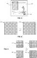
- FIG. 4illustrates an example of a set of dither patterns for achieving a 50% transparency of an area of the graphics plane 200.
- a first dither pattern 410includes the color key value (such as purple, indicated with a "p" in the pixel box) for every other pixel, while a second dither pattern 420 is the opposite of the first pattern 410.
- each of these patterns 410 and 420has the effect of reassigning the color of every other pixel from the original graphics on the graphics plane 200 with that of the color key value.
- Each pattern 410 and 420thus allows half of the pixels from the video overlay plane 250 to be displayed through the content of the graphics plane 200.
- the patterns 410 and 420are then applied in an alternating fashion to successive frames of the graphics plane 200, which creates a more pleasing partial transparency effect and avoid aliasing and other artifacts.
- the dither patterns 410 and 420may be applied to a portion of or the entire graphics plane 200, depending on the desired effect.
- FIG. 5illustrates a set of dither patterns, 510, 520, 530, and 540, where a particular pixel in each 2x2 set of pixels is assigned the value of the color key.
- a time-averaged 25% transparency effectcan be achieved.
- a 75% transparencycan be achieved by revering the pixels that are assigned the color key value in patterns 510, 520, 530, and 540.
- a variety of other transparency levelsmay be achieved using other combinations of patterns.
- other randomized or pseudo-randomized dither patterns of color keysincluding randomized Floyd-Steinberg dither patterns, may be used in embodiments of the display system.
- the number of patterns that can be usedmay depend in practical applications on the video frame rate (or refresh rate) of the system and the minimum allowable cycle rate of the patterns.
- the following tablepresents the transparency achieved and the cycle rate of the patterns for an example display system that has a 70 Hz frame rate. Transparency Cycle Rate 100 % 70 Hz 75 % 17.5 Hz 50 % 35 Hz 25 % 17.5 Hz 0 % 70 Hz
- the cycle rateis the full video frame rate of 70 Hz (i.e., there are no alternating patterns).
- 70 Hzi.e., there are no alternating patterns.
- two patternsare used.
- the full cycle of patternsoccurs at 35 Hz.
- 25% or 75% transparenciesas shown in FIG. 5 , four patterns are used, so the cycle of patterns repeats at 17.5 Hz.
- the display system 100renders multiple versions of a graphic (such as the menu 220 in FIG. 3 ) or multiple versions of an entire graphics plane 200.
- the display system 100applies a different dither pattern of color keys, as described above, producing multiple graphics that can be cycled through to achieve the time-averaged partial transparency effect.
- the display system 100cycles through each of these pre-rendered graphics. This creates a time-averaging of the dither patterns, resulting in a partial transparent effect of the graphics in the resulting video stream.
- Another embodiment of the inventionis used to avoid aliasing of a graphic displayed against a video overlay, such as the textual graphic 240 shown in FIG. 3 .
- Aliasingcan occur when a curved or diagonal image is displayed against a contrasting color, causing noticeable abrupt steps in the image to be seen against the background color.
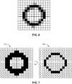
- One technique to avoid aliasing in this contextis to blend the colors between the graphic and its background at pixels near the edge of the graphic. An example of this is illustrated in FIG. 6 , where a graphic (e.g., a circle, or the letter "o") is black against a white background, and pixels near the edges of the graphic are gray. The grayed pixels help to reduce the aliasing effect of the black discrete pixels against the white background.
- FIG. 7illustrates a pair of patterns 710 and 720 of a graphics plane that correspond to the graphic shown in FIG. 6 .
- the blending effect of the grayed pixels in FIG. 6can be achieved in the time domain by alternating between graphics planes in which these pixels are present (i.e., black) in one video frame and then not present (i.e., assigned to the color key) in another video frame.
- the pixels near the edge of the graphicwill have a time-averaged blending between the graphic in the graphics plane and the content of the video overlay plane.
- the use of the two patterns 710 and 720 in an alternating fashionachieves a 50% blending effect, corresponding to a 50% gray pixel used for a black graphic on a white background.
- additional patternscan be used, and/or timings other than alternating the patterns 710 and 720 can be used.
- the pattern 720could be used in two video frames for each use of pattern 710 in a video frame. Any number of patterns and timings are possible, although video frame rates and minimum acceptable cycle rates may limit the quality of the resulting video stream.
- a software moduleis implemented with a computer program product comprising a computer-readable medium containing computer program code, which can be executed by a computer processor for performing any or all of the steps, operations, or processes described.
- Embodiments of the inventionmay also relate to an apparatus for performing the operations herein.
- This apparatusmay be specially constructed for the required purposes, and/or it may comprise a general-purpose computing device selectively activated or reconfigured by a computer program stored in the computer.
- a computer programmay be stored in a tangible computer readable storage medium or any type of media suitable for storing electronic instructions, and coupled to a computer system bus.
- any computing systems referred to in the specificationmay include a single processor or may be architectures employing multiple processor designs for increased computing capability.
- Embodiments of the inventionmay also relate to a computer data signal embodied in a carrier wave, where the computer data signal includes any embodiment of a computer program product or other data combination described herein.
- the computer data signalis a product that is presented in a tangible medium or carrier wave and modulated or otherwise encoded in the carrier wave, which is tangible, and transmitted according to any suitable transmission method.
Landscapes
- Engineering & Computer Science (AREA)
- Physics & Mathematics (AREA)
- Computer Hardware Design (AREA)
- General Physics & Mathematics (AREA)
- Theoretical Computer Science (AREA)
- Multimedia (AREA)
- Signal Processing (AREA)
- Controls And Circuits For Display Device (AREA)
- Image Generation (AREA)
Description
- This invention relates generally to digital graphics, and in particular to blending of graphics with a video overlay to achieve effects such as partial transparency and/or anti-aliasing.
- The combination of graphics and video overlays is used in a wide variety of display systems. For example, while a television system receives and displays a broadcast program, the television system may also display graphics such as channel information and other menus or controls on the screen. The television system generates these graphics and then combines them with the broadcast program for display at the same time. Computing devices, such as computer systems and mobile phones, may also combine graphics and video overlays. For example, a computing device may display a streaming video on the device's display while also drawing graphics on the screen over the video, such as a cursor or menu.
- One technique for combining graphics and video in a display system is called color keying (or chroma keying). In this technique, a particular color is defined as a color key. For each pixel in each frame, the display system will draw pixel from the graphics plane unless the color value of that pixel matches the color key, in which event the display system draws the corresponding pixel from the video overlay instead. Color keying is thus used to control which plane is visible, the graphics or the video overlay, on a per-pixel basis for each frame. In essence, the color key represents a fully transparent pixel in the graphics plane that allows the corresponding pixel in the video overlay plane to be seen.
- In some applications, it is desirable to blend the graphics and video overlays so that the pixels drawn are a blend of the colors from each plane, rather than just being one or the other. Such an effect may be desirable, for example, to provide a partially transparent graphic (such as a menu) or to reduce aliasing of diagonal or round graphics against the video overlay. But traditional uses of color keys do not enable partially transparency of the graphics, since with color keying either the pixel from the graphics plane or the pixel from the video overlay plane is drawn. This binary nature of the pixels prevents partial transparency, and it may cause diagonal or round graphics to look jagged due to aliasing.
- One technique for achieving partial transparency is known as alpha blending. In this technique, the pixel drawn on the display is a weighted average of the corresponding pixels from graphics and video overlays. For example, the following equation may be used to compure each channel of the pixel colour, where the ratioα controls the blending between the graphics and video layers: final_pixel = graphics_pixel (1-α) + video_pixel (α). This computation is performed for each pixel of each rendered frame. Although alpha blending enables a high level of blending control, this technique is computationally expensive and not always possible.
- What are needed are techniques that enable transparency and/or reduce aliasing in a display system for graphics and video overlay using colour keys.
US2007/0103489 is directed to a graphics integrated chip for use in a set-top box controlling a television display.US6151030 relates to a method of creating transparent graphics for display in a computer system.
Kasai et al(Development of 13.3-in. Super TFT-LCD Monitor, SID-96) is related to the development of super TFT-LCD monitors.US 6023302 is directed towards a graphics blending feature.US 2005/117805 is directed towards compression of digital video images. - The
independent claims 1, 7, and 8 define the matter for which protection is sought. A display system combines a graphics plane and a video overlay plane using colour keys in the graphics plane. By time-averaging patterns of color keys in successive frames of the graphics plane, individual pixels of the graphics plane can be made to appear partially transparent. For example, the display system may use time varying color key patterns over an impression similar to that of alpha blending between the graphics and video overlay, without requiring the use of alpha blending. The amount of blending between the graphic and video overlay planes may be controlled by using more or fewer color keys averaged across multiple video frames. - Embodiments of the invention may be used to draw portions of a graphic plane that appear partially transparent with respect to the video overlay plane. This effect may be achieved, for example, by applying one or more dither patterns of color keys to the desired portion of the graphics plane, and then cycling through the patterns for successive video frames. In other embodiments, the color key may be selectively applied to make individual pixels in the graphics plane partially transparent. In this way, anti-aliasing can be achieved by blending individual pixels near the edges of graphics in the graphics plane with the video plane.
- The computing resources needed to support embodiments of the invention can be much lower than those required for software-based alpha blending of the graphics and video overlay planes. Moreover, using regular dither patterns and pre-rendering only the affected area, CPU cycles can be kept relatively low.
FIG. 1 is a schematic of a display system, in accordance with an embodiment of the invention.FIG. 2 illustrates a graphics plane and a video overlay plane, in accordance with an embodiment of the invention.FIG. 3 illustrates a video frame resulting from the combination of the graphics and video overlay planes ofFIG. 2 , in accordance with an embodiment of the invention.FIG. 4 illustrates a set of dither patterns for color keys of a graphics plane for achieving 50% transparency, in accordance with an embodiment of the invention.FIG. 5 illustrates a set of dither patterns for color keys of a graphics plane for achieving 25% transparency, in accordance with an embodiment of the invention.FIG. 6 illustrates an image of a graphic using grayscale to avoid aliasing.FIG. 7 illustrates a set of graphics planes for performing anti-aliasing using time-averaged video blending, in accordance with an embodiment of the invention.- The figures depict various embodiments of the invention for purposes of illustration only. One skilled in the art will readily recognize from the following discussion that alternative embodiments of the structures and methods illustrated herein may be employed without departing from the principles of the invention described herein.
FIG. 1 illustrates an embodiment of adisplay system 100, which comprises adisplay 110, adisplay controller 120, amemory 130, and avideo blending module 140. Thedisplay system 100 may be part of including without limitation a television system, a cellular phone, a portable computing device, or any other type of system that enables viewing of video. In various types of systems and configuration, thedisplay 110, thedisplay controller 120, and thememory 130 may be any of a variety of components that are well known in the art for their corresponding functions. Thevideo blending module 140, by which embodiments of the invention are enabled, may be implemented as software, hardware, or any combination thereof.- In video systems, graphics and video streams are often combined in a series of video frames, where each video frame is a combination of a
graphics plane 200 and avideo overlay plane 250, as illustrated in the example ofFIG. 2 . A frame in thegraphics plane 200 may comprise graphics generated locally by a graphics module (not shown) in thedisplay system 100, stored temporarily in thememory 130, or received from an external source. Similarly, a frame of thevideo overlay plane 250 may comprise frames from a video stream received from an external source (e.g., in the case of a television broadcast program), or an internal sources (e.g., in the case of a file stored in thememory 130 and decoded by a processor). - In one embodiment, to generate a video frame for the
display system 100, thevideo blending module 140 combines agraphics plane 200 and avideo overlay plane 250 using color keys in the graphics plane. This process is known as color keying or chroma keying. In this process, a particular color (or range of colors) is defined as a color key. For example, a pure, bright purple (e.g., in an RGB system, defined as: (255 0 255)) may be defined as the color key, as the color is less likely to be used in the graphics than other colors. For each pixel in each video frame to be rendered, thevideo blending module 140 draws the pixel from thegraphics plane 200 unless the color value of that pixel matches the color key. If the pixel does match the color key, thevideo blending module 140 draws the corresponding pixel from thevideo overlay plane 250 instead. This allows the video overlay and the graphics to be blended using the color key to pass through the video overlay in portions of the display as desired. If only video overlay and no graphics are desired, thegraphics plane 200 can be configured with every pixel therein set to the color key. - In an embodiment of the invention, to enable partial transparency of selected pixels and/or selected areas on the screen, the
video blending module 140 is configured to perform time-averaging of color keys in successive frames of thegraphics plane 200. In this way, a selected region in the graphics plane 200 (e.g., a menu) can be partially transparent with respect to corresponding regions of thevideo overlay plane 250.FIG. 3 illustrates an example of a combination of thegraphics plane 200 and thevideo overlay plane 250 that are shown inFIG. 2 . In the resulting video frame, a graphic 220 (e.g., a menu) is displayed as partially transparent with respect to thevideo frame 230. In addition, aliasing of graphics in thegraphics plane 200 can be reduced by making selected pixels in thegraphics plane 200 partially transparent. The anti-aliasing effect may be achieved by making partially transparent selected pixels near the borders of another graphic 240 (e.g., text that indicates a current channel). Specific embodiments of these techniques are described in more detail below. - A graphic in the graphics plane 200 (such as
menu 220 inFIG. 3 ) can be made to appear partially transparent with respect to the content of thevideo overlay plane 250, in one embodiment, by applying a time-averaged dither pattern of color keyed pixels to the area of thegraphics plane 200 that is desired to be partially transparent. FIG. 4 illustrates an example of a set of dither patterns for achieving a 50% transparency of an area of thegraphics plane 200. Afirst dither pattern 410 includes the color key value (such as purple, indicated with a "p" in the pixel box) for every other pixel, while asecond dither pattern 420 is the opposite of thefirst pattern 410. When applied to a portion of the graphics plane, each of thesepatterns graphics plane 200 with that of the color key value. Eachpattern video overlay plane 250 to be displayed through the content of thegraphics plane 200. Thepatterns graphics plane 200, which creates a more pleasing partial transparency effect and avoid aliasing and other artifacts. Thedither patterns entire graphics plane 200, depending on the desired effect.- Other levels of blending can be achieved with different dither patterns and/or different timings of application of the patterns. For example,
FIG. 5 illustrates a set of dither patterns, 510, 520, 530, and 540, where a particular pixel in each 2x2 set of pixels is assigned the value of the color key. By alternating among these four dither patterns, a time-averaged 25% transparency effect can be achieved. It can be appreciated that a 75% transparency can be achieved by revering the pixels that are assigned the color key value inpatterns - The number of patterns that can be used may depend in practical applications on the video frame rate (or refresh rate) of the system and the minimum allowable cycle rate of the patterns. The following table presents the transparency achieved and the cycle rate of the patterns for an example display system that has a 70 Hz frame rate.
Transparency Cycle Rate 100 % 70 Hz 75 % 17.5 Hz 50 % 35 Hz 25 % 17.5 Hz 0 % 70 Hz - For 100% transparency the graphics plane contains all color keys, and for 0% transparency the graphics plane contains none. Therefore, the cycle rate is the full video frame rate of 70 Hz (i.e., there are no alternating patterns). For a 50% transparency, such as in
FIG. 4 , two patterns are used. Thus, the full cycle of patterns occurs at 35 Hz. For 25% or 75% transparencies, as shown inFIG. 5 , four patterns are used, so the cycle of patterns repeats at 17.5 Hz. These values are merely presented as examples, and other transparencies and rates are possible. For example, if a cycle rate of 7 Hz is acceptable, the system can achieve a 10% transparency, or any multiple thereof. - In one embodiment, the
display system 100 renders multiple versions of a graphic (such as themenu 220 inFIG. 3 ) or multiple versions of anentire graphics plane 200. To render each version, thedisplay system 100 applies a different dither pattern of color keys, as described above, producing multiple graphics that can be cycled through to achieve the time-averaged partial transparency effect. Accordingly, when combining thegraphics plane 200 andvideo overlay plane 250 to produce successive frames of video, thedisplay system 100 cycles through each of these pre-rendered graphics. This creates a time-averaging of the dither patterns, resulting in a partial transparent effect of the graphics in the resulting video stream. - Another embodiment of the invention is used to avoid aliasing of a graphic displayed against a video overlay, such as the textual graphic 240 shown in
FIG. 3 . Aliasing can occur when a curved or diagonal image is displayed against a contrasting color, causing noticeable abrupt steps in the image to be seen against the background color. One technique to avoid aliasing in this context is to blend the colors between the graphic and its background at pixels near the edge of the graphic. An example of this is illustrated inFIG. 6 , where a graphic (e.g., a circle, or the letter "o") is black against a white background, and pixels near the edges of the graphic are gray. The grayed pixels help to reduce the aliasing effect of the black discrete pixels against the white background. But the traditional technique of blending the colors of the graphic and the background at pixels near the edge of the image cannot work in a video blending system if the system does not know the content of the video overlay when rendering the graphics plane. And even if the video overlay is known, this blending might require an alpha-blending technique, which may be undesirable. - To address the aliasing issue, an embodiment of the invention uses time-averaged blending of pixels near an edge of a graphic rather than blending in the color domain.
FIG. 7 illustrates a pair ofpatterns FIG. 6 . The blending effect of the grayed pixels inFIG. 6 can be achieved in the time domain by alternating between graphics planes in which these pixels are present (i.e., black) in one video frame and then not present (i.e., assigned to the color key) in another video frame. By alternating thesepatterns - The use of the two
patterns patterns pattern 720 could be used in two video frames for each use ofpattern 710 in a video frame. Any number of patterns and timings are possible, although video frame rates and minimum acceptable cycle rates may limit the quality of the resulting video stream. - The foregoing description of the embodiments of the invention has been presented for the purpose of illustration; it is not intended to be exhaustive or to limit the invention to the precise forms disclosed. Persons skilled in the relevant art can appreciate that many modifications and variations are possible in light of the above disclosure.
- Some portions of this description describe the embodiments of the invention in terms of algorithms and symbolic representations of operations on information. These algorithmic descriptions and representations are commonly used by those skilled in the data processing arts to convey the substance of their work effectively to others skilled in the art. These operations, while described functionally, computationally, or logically, are understood to be implemented by computer programs or equivalent electrical circuits, microcode, or the like. Furthermore, it has also proven convenient at times, to refer to these arrangements of operations as modules, without loss of generality. The described operations and their associated modules may be embodied in software, firmware, hardware, or any combinations thereof.
- Any of the steps, operations, or processes described herein may be performed or implemented with one or more hardware or software modules, alone or in combination with other devices. In one embodiment, a software module is implemented with a computer program product comprising a computer-readable medium containing computer program code, which can be executed by a computer processor for performing any or all of the steps, operations, or processes described.
- Embodiments of the invention may also relate to an apparatus for performing the operations herein. This apparatus may be specially constructed for the required purposes, and/or it may comprise a general-purpose computing device selectively activated or reconfigured by a computer program stored in the computer. Such a computer program may be stored in a tangible computer readable storage medium or any type of media suitable for storing electronic instructions, and coupled to a computer system bus. Furthermore, any computing systems referred to in the specification may include a single processor or may be architectures employing multiple processor designs for increased computing capability.
- Embodiments of the invention may also relate to a computer data signal embodied in a carrier wave, where the computer data signal includes any embodiment of a computer program product or other data combination described herein. The computer data signal is a product that is presented in a tangible medium or carrier wave and modulated or otherwise encoded in the carrier wave, which is tangible, and transmitted according to any suitable transmission method.
- Finally, the language used in the specification has been principally selected for readability and instructional purposes, and it may not have been selected to delineate or circumscribe the inventive subject matter. It is therefore intended that the scope of the invention be limited not by this detailed description, but rather by any claims that issue on an application based hereon. Accordingly, the disclosure of the embodiments of the invention is intended to be illustrative, but not limiting, of the scope of the invention, which is set forth in the following claims.
Claims (10)
- A method for video blending of graphics and video content for a display system, the method comprising:rendering one or more graphics items for display with the video content;generating a series of graphics planes (200) containing the rendered one or more graphics items, the series of graphics planes (200) comprising;a first graphics plane with a first dither pattern of colour keyed pixels (410) applied to it, by which applying the colour of those pixels from the rendered graphics are replaced by the color key value, at pixels where the colour key value is present in the first dither pattern; anda second graphics plane with a second dither pattern of colour keyed pixels (420) applied to it, by which applying the colour of those pixels from the rendered graphics are replaced by the color key value, at pixels where the colour key value is present in the second dither pattern, wherein the second dither pattern is different from the first dither pattern;receiving the video content as a series of video overlay planes (250);generating, with a hardware processor, a series of video frames comprising a time-averaged blending of the one or more graphics items and the video content by combining each video overlay plane of the series of video overlay planes with one of the first graphics plane and second graphics plane in alternating fashion between the first graphics plane and the second graphics plane, the combining of a video overlay plane with one of the first graphics plane and the second graphics plane being achieved by drawing a pixel from the graphics plane unless the colour value of said pixel matches the color key, otherwise drawing the pixel from the video overlay plane instead, to create a time-averaged partial transparency effect of the one or more graphics items with respect to the video content; andoutputting the series of video frames for display on the display system (100).
- The method of claim 1, wherein each of the generated series of graphics planes includes an area containing the rendered one or more graphics items and at least one of the first dither pattern and second dither pattern, thereby producing a partial transparency of the one or more graphics items in the generated series of video frames.
- The method of claim 1, wherein each of the first dither pattern and second dither pattern is a randomized Floyd-Steinberg dither pattern.
- The method of claim 1, wherein a plurality of pixels adjoining pixels at an edge of a graphics item have a color value equal to the color key in one or more of the graphics planes and a color value not equal to the color key in one or more of the graphics planes, thereby reducing aliasing around the graphics object.
- The method of claim 1, wherein the series of graphics
planes comprises a sequence of three of more graphics planes. - The method of claim 1, wherein the series of graphics
planes comprises a sequence of graphics planes containing at least two instances of a particular graphics plane. - A computer program product for video blending of graphics and video content for a display system, the computer program product comprising a computer-readable medium containing computer program code for performing the method comprising the steps of any one of claims 1 to 6.
- A display system (100) comprising:a display (110);a memory;a processor;a display controller (120) coupled to the display for controlling video frames reproduced on the display; anda video blending module (140) stored in the memory, the video blending module configured to:render one or more graphics items for display with content from a video overlay,
generate a series of graphics planes (200) containing the rendered one or more graphics items, the series of graphics planes comprising:a first graphics plane with a first dither pattern of colour keyed pixels (410) applied to it, by which applying the colour of those pixels from the rendered graphics are replaced by the color key value, at pixels where the colour key value is present in the first dither pattern; anda second graphics plane with a second dither pattern of colour keyed pixels (420) applied to it, by which applying the colour of those pixels from the rendered graphics are replaced by the color key value, at pixels where the colour key value is present in the second dither pattern, wherein the second dither pattern is different from the first dither pattern;receive the video overlay content as a series of video overlay planes (250);generating, with a hardware processor, a series of video frames comprising a time-averaged blending of the one or more graphics items and the video content by combining each video overlay plane of the series of video overlay planes with one of the first graphics plane and second graphics plane in alternating fashion between the first graphics plane and the second graphics plane, the combining of a video overlay plane with one of the first graphics plane and the second graphics plane being achieved by drawing a pixel from the graphics plane unless the colour value of said pixel matches the color key, otherwise drawing the pixel from the video overlay plane instead, to create a time-averaged partial transparency effect of the one or more graphics items with respect to the video content; andoutput the series of video frames to the display controller for reproduction on the display. - The display of claim 8, wherein the video blending module is configured to generate a series of graphics planes that include an area containing the rendered one or more graphics items and at least one of the first dither pattern and second dither pattern, thereby producing a partial transparency of the one or more graphics items in the generated series of video frames.
- The display of claim 8, wherein the video blending module is configured to generate graphics planes in which a plurality of pixels adjoining pixels at an edge of a graphics item have a color value equal to the color key in one or more of the graphics planes and a color value not equal to the color key in one or more of the graphics planes, thereby reducing aliasing around the graphics object.
Applications Claiming Priority (2)
| Application Number | Priority Date | Filing Date | Title |
|---|---|---|---|
| US11/852,187US9024966B2 (en) | 2007-09-07 | 2007-09-07 | Video blending using time-averaged color keys |
| PCT/US2008/072654WO2009032476A1 (en) | 2007-09-07 | 2008-08-08 | Video blending using time-averaged color keys |
Publications (3)
| Publication Number | Publication Date |
|---|---|
| EP2208195A1 EP2208195A1 (en) | 2010-07-21 |
| EP2208195A4 EP2208195A4 (en) | 2011-01-19 |
| EP2208195B1true EP2208195B1 (en) | 2017-10-18 |
Family
ID=40429275
Family Applications (1)
| Application Number | Title | Priority Date | Filing Date |
|---|---|---|---|
| EP08829786.6ANot-in-forceEP2208195B1 (en) | 2007-09-07 | 2008-08-08 | Video blending using time-averaged color keys |
Country Status (3)
| Country | Link |
|---|---|
| US (1) | US9024966B2 (en) |
| EP (1) | EP2208195B1 (en) |
| WO (1) | WO2009032476A1 (en) |
Families Citing this family (13)
| Publication number | Priority date | Publication date | Assignee | Title |
|---|---|---|---|---|
| US8861591B2 (en)* | 2007-05-11 | 2014-10-14 | Advanced Micro Devices, Inc. | Software video encoder with GPU acceleration |
| US8233527B2 (en)* | 2007-05-11 | 2012-07-31 | Advanced Micro Devices, Inc. | Software video transcoder with GPU acceleration |
| TWI357034B (en)* | 2007-09-28 | 2012-01-21 | Mstar Semiconductor Inc | Dithering mask and method of forming the same |
| JP4950834B2 (en)* | 2007-10-19 | 2012-06-13 | キヤノン株式会社 | Image processing apparatus and image processing method |
| RU2010123179A (en)* | 2007-11-08 | 2011-12-20 | Кониклейке Филипс Электроникс Н.В. (Nl) | DISPLAY PIXELS EXCITATION |
| WO2009108345A2 (en)* | 2008-02-27 | 2009-09-03 | Ncomputing Inc. | System and method for low bandwidth display information transport |
| US8125495B2 (en)* | 2008-04-17 | 2012-02-28 | Microsoft Corporation | Displaying user interface elements having transparent effects |
| US8723891B2 (en)* | 2009-02-27 | 2014-05-13 | Ncomputing Inc. | System and method for efficiently processing digital video |
| US9734610B2 (en)* | 2013-03-13 | 2017-08-15 | Rakuten, Inc. | Image processing device, image processing method, and image processing program |
| US20150109463A1 (en)* | 2013-10-19 | 2015-04-23 | Motorola Solutions, Inc | Method and system for generating modified display data |
| US10290110B2 (en)* | 2016-07-05 | 2019-05-14 | Intel Corporation | Video overlay modification for enhanced readability |
| US10728492B2 (en)* | 2017-04-24 | 2020-07-28 | Intel Corporation | Synergistic temporal anti-aliasing and coarse pixel shading technology |
| WO2021107202A1 (en)* | 2019-11-28 | 2021-06-03 | 주식회사 지이모션 | Three-dimensional modeling method of clothing |
Family Cites Families (26)
| Publication number | Priority date | Publication date | Assignee | Title |
|---|---|---|---|---|
| US5889499A (en)* | 1993-07-29 | 1999-03-30 | S3 Incorporated | System and method for the mixing of graphics and video signals |
| WO1996020470A1 (en)* | 1994-12-23 | 1996-07-04 | Philips Electronics N.V. | Single frame buffer image processing system |
| US5790124A (en)* | 1995-11-20 | 1998-08-04 | Silicon Graphics, Inc. | System and method for allowing a performer to control and interact with an on-stage display device |
| US6023302A (en)* | 1996-03-07 | 2000-02-08 | Powertv, Inc. | Blending of video images in a home communications terminal |
| US6532022B1 (en)* | 1997-10-15 | 2003-03-11 | Electric Planet, Inc. | Method and apparatus for model-based compositing |
| US6151030A (en)* | 1998-05-27 | 2000-11-21 | Intel Corporation | Method of creating transparent graphics |
| US6573905B1 (en)* | 1999-11-09 | 2003-06-03 | Broadcom Corporation | Video and graphics system with parallel processing of graphics windows |
| US6731295B1 (en)* | 1998-11-09 | 2004-05-04 | Broadcom Corporation | Graphics display system with window descriptors |
| US6636222B1 (en)* | 1999-11-09 | 2003-10-21 | Broadcom Corporation | Video and graphics system with an MPEG video decoder for concurrent multi-row decoding |
| US6853385B1 (en)* | 1999-11-09 | 2005-02-08 | Broadcom Corporation | Video, audio and graphics decode, composite and display system |
| US7623140B1 (en)* | 1999-03-05 | 2009-11-24 | Zoran Corporation | Method and apparatus for processing video and graphics data to create a composite output image having independent and separate layers of video and graphics |
| US6335765B1 (en)* | 1999-11-08 | 2002-01-01 | Weather Central, Inc. | Virtual presentation system and method |
| US7006155B1 (en)* | 2000-02-01 | 2006-02-28 | Cadence Design Systems, Inc. | Real time programmable chroma keying with shadow generation |
| US6844882B1 (en)* | 2000-12-13 | 2005-01-18 | Adobe Systems Incorporated | Variable dithering for GIF |
| KR20030023711A (en)* | 2001-05-23 | 2003-03-19 | 코닌클리케 필립스 일렉트로닉스 엔.브이. | Dithering method and dithering device |
| DE10126790A1 (en)* | 2001-06-01 | 2003-01-02 | Micronas Munich Gmbh | Method and device for displaying at least two images in an overall image |
| US7098927B2 (en)* | 2002-02-01 | 2006-08-29 | Sharp Laboratories Of America, Inc | Methods and systems for adaptive dither structures |
| US6982727B2 (en)* | 2002-07-23 | 2006-01-03 | Broadcom Corporation | System and method for providing graphics using graphical engine |
| US20040194128A1 (en)* | 2003-03-28 | 2004-09-30 | Eastman Kodak Company | Method for providing digital cinema content based upon audience metrics |
| DE10345898A1 (en)* | 2003-07-11 | 2005-01-27 | Tesa Scribos Gmbh | Computer-based method for generation of a hologram with an overlay structure such as a motif, whereby the hologram pixel distribution and the macroscopic overlay pixel distribution are linked and written to a memory |
| US8243093B2 (en)* | 2003-08-22 | 2012-08-14 | Sharp Laboratories Of America, Inc. | Systems and methods for dither structure creation and application for reducing the visibility of contouring artifacts in still and video images |
| EP1515278B1 (en)* | 2003-09-11 | 2007-02-28 | STMicroelectronics S.r.l. | Video compression using dithering |
| US7352373B2 (en)* | 2003-09-30 | 2008-04-01 | Sharp Laboratories Of America, Inc. | Systems and methods for multi-dimensional dither structure creation and application |
| WO2007065224A1 (en)* | 2005-12-05 | 2007-06-14 | Commonwealth Scientific And Industrial Research Organisation | A method of forming a securitized image |
| US8120623B2 (en)* | 2006-03-15 | 2012-02-21 | Kt Tech, Inc. | Apparatuses for overlaying images, portable devices having the same and methods of overlaying images |
| US20080284798A1 (en)* | 2007-05-07 | 2008-11-20 | Qualcomm Incorporated | Post-render graphics overlays |
- 2007
- 2007-09-07USUS11/852,187patent/US9024966B2/ennot_activeExpired - Fee Related
- 2008
- 2008-08-08EPEP08829786.6Apatent/EP2208195B1/ennot_activeNot-in-force
- 2008-08-08WOPCT/US2008/072654patent/WO2009032476A1/enactiveApplication Filing
Non-Patent Citations (1)
| Title |
|---|
| None* |
Also Published As
| Publication number | Publication date |
|---|---|
| WO2009032476A1 (en) | 2009-03-12 |
| EP2208195A1 (en) | 2010-07-21 |
| US9024966B2 (en) | 2015-05-05 |
| EP2208195A4 (en) | 2011-01-19 |
| US20090066716A1 (en) | 2009-03-12 |
Similar Documents
| Publication | Publication Date | Title |
|---|---|---|
| EP2208195B1 (en) | Video blending using time-averaged color keys | |
| US8698840B2 (en) | Method and apparatus for processing video and graphics data to create a composite output image having independent and separate layers of video and graphics display planes | |
| TW536913B (en) | Blending text and graphics for display on televisions | |
| JP5439588B2 (en) | Apparatus and method for processing image data for display on a display panel | |
| WO2017112360A1 (en) | Video tone mapping for converting high dynamic range (hdr) content to standard dynamic range (sdr) content | |
| KR20060109451A (en) | Smart Clipper for Mobile Display | |
| EP2195705A1 (en) | Display device | |
| US20140292631A1 (en) | Backlight modulation over external display interfaces to save power | |
| US8879834B2 (en) | Method and apparatus for reduced complexity video processing via special chroma handling | |
| US20140111537A1 (en) | Color enhancement via gamut expansion | |
| JP2006154064A (en) | Display method and display device | |
| KR20240012396A (en) | High-quality UI element borders using masks in temporally interpolated frames. | |
| US7684638B2 (en) | Dynamic image contrast enhancement device | |
| US20140132618A1 (en) | Electronic device and method for enhancing readability of an image thereof | |
| EP4318373A1 (en) | Secure graphics watermark | |
| JP2017175422A (en) | Image display device and television apparatus | |
| US10484640B2 (en) | Low power video composition using a stream out buffer | |
| US7590302B1 (en) | Image edge enhancement system and method | |
| Elliott et al. | 72.1: Invited Paper: PenTile RGBW® Color Processing | |
| US12354249B2 (en) | Chroma correction of inverse gamut mapping for standard dynamic range to high dynamic range image conversion | |
| US20040150654A1 (en) | Sparkle reduction using a split gamma table | |
| Jung et al. | Power constrained contrast enhancement based on brightness compensated contrast-tone mapping operation | |
| KR20060025004A (en) | Display device | |
| WO2009125342A1 (en) | Electronic device and method of enhancing the picture quality of composite video data having at least one window | |
| KR20070074385A (en) | On-Screen Display and Control Method |
Legal Events
| Date | Code | Title | Description |
|---|---|---|---|
| PUAI | Public reference made under article 153(3) epc to a published international application that has entered the european phase | Free format text:ORIGINAL CODE: 0009012 | |
| 17P | Request for examination filed | Effective date:20100401 | |
| AK | Designated contracting states | Kind code of ref document:A1 Designated state(s):AT BE BG CH CY CZ DE DK EE ES FI FR GB GR HR HU IE IS IT LI LT LU LV MC MT NL NO PL PT RO SE SI SK TR | |
| AX | Request for extension of the european patent | Extension state:AL BA MK RS | |
| DAX | Request for extension of the european patent (deleted) | ||
| RAP1 | Party data changed (applicant data changed or rights of an application transferred) | Owner name:HEWLETT-PACKARD DEVELOPMENT COMPANY, L.P. | |
| A4 | Supplementary search report drawn up and despatched | Effective date:20101217 | |
| RAP1 | Party data changed (applicant data changed or rights of an application transferred) | Owner name:QUALCOMM INCORPORATED | |
| 17Q | First examination report despatched | Effective date:20150610 | |
| REG | Reference to a national code | Ref country code:DE Ref legal event code:R079 Ref document number:602008052562 Country of ref document:DE Free format text:PREVIOUS MAIN CLASS: G09G0005000000 Ipc:G09G0003200000 | |
| GRAP | Despatch of communication of intention to grant a patent | Free format text:ORIGINAL CODE: EPIDOSNIGR1 | |
| RIC1 | Information provided on ipc code assigned before grant | Ipc:G09G 3/20 20060101AFI20160725BHEP | |
| INTG | Intention to grant announced | Effective date:20160816 | |
| GRAJ | Information related to disapproval of communication of intention to grant by the applicant or resumption of examination proceedings by the epo deleted | Free format text:ORIGINAL CODE: EPIDOSDIGR1 | |
| STAA | Information on the status of an ep patent application or granted ep patent | Free format text:STATUS: GRANT OF PATENT IS INTENDED | |
| GRAJ | Information related to disapproval of communication of intention to grant by the applicant or resumption of examination proceedings by the epo deleted | Free format text:ORIGINAL CODE: EPIDOSDIGR1 | |
| STAA | Information on the status of an ep patent application or granted ep patent | Free format text:STATUS: EXAMINATION IS IN PROGRESS | |
| INTG | Intention to grant announced | Effective date:20160816 | |
| INTC | Intention to grant announced (deleted) | ||
| GRAP | Despatch of communication of intention to grant a patent | Free format text:ORIGINAL CODE: EPIDOSNIGR1 | |
| STAA | Information on the status of an ep patent application or granted ep patent | Free format text:STATUS: GRANT OF PATENT IS INTENDED | |
| INTG | Intention to grant announced | Effective date:20170217 | |
| GRAJ | Information related to disapproval of communication of intention to grant by the applicant or resumption of examination proceedings by the epo deleted | Free format text:ORIGINAL CODE: EPIDOSDIGR1 | |
| STAA | Information on the status of an ep patent application or granted ep patent | Free format text:STATUS: EXAMINATION IS IN PROGRESS | |
| INTC | Intention to grant announced (deleted) | ||
| GRAJ | Information related to disapproval of communication of intention to grant by the applicant or resumption of examination proceedings by the epo deleted | Free format text:ORIGINAL CODE: EPIDOSDIGR1 | |
| GRAP | Despatch of communication of intention to grant a patent | Free format text:ORIGINAL CODE: EPIDOSNIGR1 | |
| GRAP | Despatch of communication of intention to grant a patent | Free format text:ORIGINAL CODE: EPIDOSNIGR1 | |
| STAA | Information on the status of an ep patent application or granted ep patent | Free format text:STATUS: GRANT OF PATENT IS INTENDED | |
| INTG | Intention to grant announced | Effective date:20170720 | |
| GRAS | Grant fee paid | Free format text:ORIGINAL CODE: EPIDOSNIGR3 | |
| GRAA | (expected) grant | Free format text:ORIGINAL CODE: 0009210 | |
| STAA | Information on the status of an ep patent application or granted ep patent | Free format text:STATUS: THE PATENT HAS BEEN GRANTED | |
| AK | Designated contracting states | Kind code of ref document:B1 Designated state(s):AT BE BG CH CY CZ DE DK EE ES FI FR GB GR HR HU IE IS IT LI LT LU LV MC MT NL NO PL PT RO SE SI SK TR | |
| REG | Reference to a national code | Ref country code:GB Ref legal event code:FG4D | |
| REG | Reference to a national code | Ref country code:CH Ref legal event code:EP | |
| REG | Reference to a national code | Ref country code:AT Ref legal event code:REF Ref document number:938573 Country of ref document:AT Kind code of ref document:T Effective date:20171115 Ref country code:IE Ref legal event code:FG4D | |
| REG | Reference to a national code | Ref country code:DE Ref legal event code:R096 Ref document number:602008052562 Country of ref document:DE | |
| REG | Reference to a national code | Ref country code:DE Ref legal event code:R082 Ref document number:602008052562 Country of ref document:DE Representative=s name:FIENER, JOSEF, DE | |
| REG | Reference to a national code | Ref country code:NL Ref legal event code:MP Effective date:20171018 | |
| REG | Reference to a national code | Ref country code:LT Ref legal event code:MG4D | |
| REG | Reference to a national code | Ref country code:AT Ref legal event code:MK05 Ref document number:938573 Country of ref document:AT Kind code of ref document:T Effective date:20171018 | |
| PG25 | Lapsed in a contracting state [announced via postgrant information from national office to epo] | Ref country code:NL Free format text:LAPSE BECAUSE OF FAILURE TO SUBMIT A TRANSLATION OF THE DESCRIPTION OR TO PAY THE FEE WITHIN THE PRESCRIBED TIME-LIMIT Effective date:20171018 | |
| PG25 | Lapsed in a contracting state [announced via postgrant information from national office to epo] | Ref country code:LT Free format text:LAPSE BECAUSE OF FAILURE TO SUBMIT A TRANSLATION OF THE DESCRIPTION OR TO PAY THE FEE WITHIN THE PRESCRIBED TIME-LIMIT Effective date:20171018 Ref country code:FI Free format text:LAPSE BECAUSE OF FAILURE TO SUBMIT A TRANSLATION OF THE DESCRIPTION OR TO PAY THE FEE WITHIN THE PRESCRIBED TIME-LIMIT Effective date:20171018 Ref country code:SE Free format text:LAPSE BECAUSE OF FAILURE TO SUBMIT A TRANSLATION OF THE DESCRIPTION OR TO PAY THE FEE WITHIN THE PRESCRIBED TIME-LIMIT Effective date:20171018 Ref country code:NO Free format text:LAPSE BECAUSE OF FAILURE TO SUBMIT A TRANSLATION OF THE DESCRIPTION OR TO PAY THE FEE WITHIN THE PRESCRIBED TIME-LIMIT Effective date:20180118 Ref country code:ES Free format text:LAPSE BECAUSE OF FAILURE TO SUBMIT A TRANSLATION OF THE DESCRIPTION OR TO PAY THE FEE WITHIN THE PRESCRIBED TIME-LIMIT Effective date:20171018 | |
| PG25 | Lapsed in a contracting state [announced via postgrant information from national office to epo] | Ref country code:GR Free format text:LAPSE BECAUSE OF FAILURE TO SUBMIT A TRANSLATION OF THE DESCRIPTION OR TO PAY THE FEE WITHIN THE PRESCRIBED TIME-LIMIT Effective date:20180119 Ref country code:BG Free format text:LAPSE BECAUSE OF FAILURE TO SUBMIT A TRANSLATION OF THE DESCRIPTION OR TO PAY THE FEE WITHIN THE PRESCRIBED TIME-LIMIT Effective date:20180118 Ref country code:IS Free format text:LAPSE BECAUSE OF FAILURE TO SUBMIT A TRANSLATION OF THE DESCRIPTION OR TO PAY THE FEE WITHIN THE PRESCRIBED TIME-LIMIT Effective date:20180218 Ref country code:AT Free format text:LAPSE BECAUSE OF FAILURE TO SUBMIT A TRANSLATION OF THE DESCRIPTION OR TO PAY THE FEE WITHIN THE PRESCRIBED TIME-LIMIT Effective date:20171018 Ref country code:HR Free format text:LAPSE BECAUSE OF FAILURE TO SUBMIT A TRANSLATION OF THE DESCRIPTION OR TO PAY THE FEE WITHIN THE PRESCRIBED TIME-LIMIT Effective date:20171018 Ref country code:LV Free format text:LAPSE BECAUSE OF FAILURE TO SUBMIT A TRANSLATION OF THE DESCRIPTION OR TO PAY THE FEE WITHIN THE PRESCRIBED TIME-LIMIT Effective date:20171018 | |
| REG | Reference to a national code | Ref country code:FR Ref legal event code:PLFP Year of fee payment:11 | |
| REG | Reference to a national code | Ref country code:DE Ref legal event code:R097 Ref document number:602008052562 Country of ref document:DE | |
| PG25 | Lapsed in a contracting state [announced via postgrant information from national office to epo] | Ref country code:SK Free format text:LAPSE BECAUSE OF FAILURE TO SUBMIT A TRANSLATION OF THE DESCRIPTION OR TO PAY THE FEE WITHIN THE PRESCRIBED TIME-LIMIT Effective date:20171018 Ref country code:CZ Free format text:LAPSE BECAUSE OF FAILURE TO SUBMIT A TRANSLATION OF THE DESCRIPTION OR TO PAY THE FEE WITHIN THE PRESCRIBED TIME-LIMIT Effective date:20171018 Ref country code:DK Free format text:LAPSE BECAUSE OF FAILURE TO SUBMIT A TRANSLATION OF THE DESCRIPTION OR TO PAY THE FEE WITHIN THE PRESCRIBED TIME-LIMIT Effective date:20171018 Ref country code:EE Free format text:LAPSE BECAUSE OF FAILURE TO SUBMIT A TRANSLATION OF THE DESCRIPTION OR TO PAY THE FEE WITHIN THE PRESCRIBED TIME-LIMIT Effective date:20171018 | |
| PLBE | No opposition filed within time limit | Free format text:ORIGINAL CODE: 0009261 | |
| STAA | Information on the status of an ep patent application or granted ep patent | Free format text:STATUS: NO OPPOSITION FILED WITHIN TIME LIMIT | |
| PG25 | Lapsed in a contracting state [announced via postgrant information from national office to epo] | Ref country code:PL Free format text:LAPSE BECAUSE OF FAILURE TO SUBMIT A TRANSLATION OF THE DESCRIPTION OR TO PAY THE FEE WITHIN THE PRESCRIBED TIME-LIMIT Effective date:20171018 Ref country code:RO Free format text:LAPSE BECAUSE OF FAILURE TO SUBMIT A TRANSLATION OF THE DESCRIPTION OR TO PAY THE FEE WITHIN THE PRESCRIBED TIME-LIMIT Effective date:20171018 Ref country code:IT Free format text:LAPSE BECAUSE OF FAILURE TO SUBMIT A TRANSLATION OF THE DESCRIPTION OR TO PAY THE FEE WITHIN THE PRESCRIBED TIME-LIMIT Effective date:20171018 | |
| 26N | No opposition filed | Effective date:20180719 | |
| PGFP | Annual fee paid to national office [announced via postgrant information from national office to epo] | Ref country code:FR Payment date:20180718 Year of fee payment:11 Ref country code:DE Payment date:20180716 Year of fee payment:11 | |
| PG25 | Lapsed in a contracting state [announced via postgrant information from national office to epo] | Ref country code:SI Free format text:LAPSE BECAUSE OF FAILURE TO SUBMIT A TRANSLATION OF THE DESCRIPTION OR TO PAY THE FEE WITHIN THE PRESCRIBED TIME-LIMIT Effective date:20171018 | |
| PGFP | Annual fee paid to national office [announced via postgrant information from national office to epo] | Ref country code:GB Payment date:20180726 Year of fee payment:11 | |
| PG25 | Lapsed in a contracting state [announced via postgrant information from national office to epo] | Ref country code:MC Free format text:LAPSE BECAUSE OF FAILURE TO SUBMIT A TRANSLATION OF THE DESCRIPTION OR TO PAY THE FEE WITHIN THE PRESCRIBED TIME-LIMIT Effective date:20171018 | |
| REG | Reference to a national code | Ref country code:CH Ref legal event code:PL | |
| PG25 | Lapsed in a contracting state [announced via postgrant information from national office to epo] | Ref country code:LI Free format text:LAPSE BECAUSE OF NON-PAYMENT OF DUE FEES Effective date:20180831 Ref country code:LU Free format text:LAPSE BECAUSE OF NON-PAYMENT OF DUE FEES Effective date:20180808 Ref country code:CH Free format text:LAPSE BECAUSE OF NON-PAYMENT OF DUE FEES Effective date:20180831 | |
| REG | Reference to a national code | Ref country code:BE Ref legal event code:MM Effective date:20180831 | |
| REG | Reference to a national code | Ref country code:IE Ref legal event code:MM4A | |
| PG25 | Lapsed in a contracting state [announced via postgrant information from national office to epo] | Ref country code:IE Free format text:LAPSE BECAUSE OF NON-PAYMENT OF DUE FEES Effective date:20180808 | |
| PG25 | Lapsed in a contracting state [announced via postgrant information from national office to epo] | Ref country code:BE Free format text:LAPSE BECAUSE OF NON-PAYMENT OF DUE FEES Effective date:20180831 | |
| PG25 | Lapsed in a contracting state [announced via postgrant information from national office to epo] | Ref country code:MT Free format text:LAPSE BECAUSE OF NON-PAYMENT OF DUE FEES Effective date:20180808 | |
| REG | Reference to a national code | Ref country code:DE Ref legal event code:R119 Ref document number:602008052562 Country of ref document:DE | |
| PG25 | Lapsed in a contracting state [announced via postgrant information from national office to epo] | Ref country code:TR Free format text:LAPSE BECAUSE OF FAILURE TO SUBMIT A TRANSLATION OF THE DESCRIPTION OR TO PAY THE FEE WITHIN THE PRESCRIBED TIME-LIMIT Effective date:20171018 | |
| GBPC | Gb: european patent ceased through non-payment of renewal fee | Effective date:20190808 | |
| PG25 | Lapsed in a contracting state [announced via postgrant information from national office to epo] | Ref country code:PT Free format text:LAPSE BECAUSE OF FAILURE TO SUBMIT A TRANSLATION OF THE DESCRIPTION OR TO PAY THE FEE WITHIN THE PRESCRIBED TIME-LIMIT Effective date:20171018 Ref country code:HU Free format text:LAPSE BECAUSE OF FAILURE TO SUBMIT A TRANSLATION OF THE DESCRIPTION OR TO PAY THE FEE WITHIN THE PRESCRIBED TIME-LIMIT; INVALID AB INITIO Effective date:20080808 | |
| PG25 | Lapsed in a contracting state [announced via postgrant information from national office to epo] | Ref country code:CY Free format text:LAPSE BECAUSE OF FAILURE TO SUBMIT A TRANSLATION OF THE DESCRIPTION OR TO PAY THE FEE WITHIN THE PRESCRIBED TIME-LIMIT Effective date:20171018 | |
| PG25 | Lapsed in a contracting state [announced via postgrant information from national office to epo] | Ref country code:FR Free format text:LAPSE BECAUSE OF NON-PAYMENT OF DUE FEES Effective date:20190831 Ref country code:DE Free format text:LAPSE BECAUSE OF NON-PAYMENT OF DUE FEES Effective date:20200303 | |
| PG25 | Lapsed in a contracting state [announced via postgrant information from national office to epo] | Ref country code:GB Free format text:LAPSE BECAUSE OF NON-PAYMENT OF DUE FEES Effective date:20190808 |