EP2207985B1 - Transmission device having a variator - Google Patents
Transmission device having a variatorDownload PDFInfo
- Publication number
- EP2207985B1 EP2207985B1EP08803049AEP08803049AEP2207985B1EP 2207985 B1EP2207985 B1EP 2207985B1EP 08803049 AEP08803049 AEP 08803049AEP 08803049 AEP08803049 AEP 08803049AEP 2207985 B1EP2207985 B1EP 2207985B1
- Authority
- EP
- European Patent Office
- Prior art keywords
- shaft
- transmission
- variator
- transmission device
- planetary gearing
- Prior art date
- Legal status (The legal status is an assumption and is not a legal conclusion. Google has not performed a legal analysis and makes no representation as to the accuracy of the status listed.)
- Not-in-force
Links
- 230000005540biological transmissionEffects0.000titleclaimsabstractdescription191
- 230000002706hydrostatic effectEffects0.000claimsdescription7
- 230000001360synchronised effectEffects0.000description17
- 238000013519translationMethods0.000description10
- 238000011161developmentMethods0.000description3
- 230000018109developmental processEffects0.000description3
- 238000000034methodMethods0.000description3
- 238000013461designMethods0.000description2
- 238000006073displacement reactionMethods0.000description2
- 238000006243chemical reactionMethods0.000description1
- 238000004891communicationMethods0.000description1
- 238000010276constructionMethods0.000description1
- 230000036461convulsionEffects0.000description1
- 238000012937correctionMethods0.000description1
- 230000006735deficitEffects0.000description1
Images


Classifications
- F—MECHANICAL ENGINEERING; LIGHTING; HEATING; WEAPONS; BLASTING
- F16—ENGINEERING ELEMENTS AND UNITS; GENERAL MEASURES FOR PRODUCING AND MAINTAINING EFFECTIVE FUNCTIONING OF MACHINES OR INSTALLATIONS; THERMAL INSULATION IN GENERAL
- F16H—GEARING
- F16H47/00—Combinations of mechanical gearing with fluid clutches or fluid gearing
- F16H47/02—Combinations of mechanical gearing with fluid clutches or fluid gearing the fluid gearing being of the volumetric type
- F16H47/04—Combinations of mechanical gearing with fluid clutches or fluid gearing the fluid gearing being of the volumetric type the mechanical gearing being of the type with members having orbital motion
- F—MECHANICAL ENGINEERING; LIGHTING; HEATING; WEAPONS; BLASTING
- F16—ENGINEERING ELEMENTS AND UNITS; GENERAL MEASURES FOR PRODUCING AND MAINTAINING EFFECTIVE FUNCTIONING OF MACHINES OR INSTALLATIONS; THERMAL INSULATION IN GENERAL
- F16H—GEARING
- F16H37/00—Combinations of mechanical gearings, not provided for in groups F16H1/00 - F16H35/00
- F16H37/02—Combinations of mechanical gearings, not provided for in groups F16H1/00 - F16H35/00 comprising essentially only toothed or friction gearings
- F16H37/06—Combinations of mechanical gearings, not provided for in groups F16H1/00 - F16H35/00 comprising essentially only toothed or friction gearings with a plurality of driving or driven shafts; with arrangements for dividing torque between two or more intermediate shafts
- F16H37/08—Combinations of mechanical gearings, not provided for in groups F16H1/00 - F16H35/00 comprising essentially only toothed or friction gearings with a plurality of driving or driven shafts; with arrangements for dividing torque between two or more intermediate shafts with differential gearing
- F16H37/0833—Combinations of mechanical gearings, not provided for in groups F16H1/00 - F16H35/00 comprising essentially only toothed or friction gearings with a plurality of driving or driven shafts; with arrangements for dividing torque between two or more intermediate shafts with differential gearing with arrangements for dividing torque between two or more intermediate shafts, i.e. with two or more internal power paths
- F16H37/084—Combinations of mechanical gearings, not provided for in groups F16H1/00 - F16H35/00 comprising essentially only toothed or friction gearings with a plurality of driving or driven shafts; with arrangements for dividing torque between two or more intermediate shafts with differential gearing with arrangements for dividing torque between two or more intermediate shafts, i.e. with two or more internal power paths at least one power path being a continuously variable transmission, i.e. CVT
- F16H2037/0866—Power-split transmissions with distributing differentials, with the output of the CVT connected or connectable to the output shaft
- F16H2037/0873—Power-split transmissions with distributing differentials, with the output of the CVT connected or connectable to the output shaft with switching means, e.g. to change ranges
- F—MECHANICAL ENGINEERING; LIGHTING; HEATING; WEAPONS; BLASTING
- F16—ENGINEERING ELEMENTS AND UNITS; GENERAL MEASURES FOR PRODUCING AND MAINTAINING EFFECTIVE FUNCTIONING OF MACHINES OR INSTALLATIONS; THERMAL INSULATION IN GENERAL
- F16H—GEARING
- F16H2200/00—Transmissions for multiple ratios
- F16H2200/003—Transmissions for multiple ratios characterised by the number of forward speeds
- F16H2200/0039—Transmissions for multiple ratios characterised by the number of forward speeds the gear ratios comprising three forward speeds
- F—MECHANICAL ENGINEERING; LIGHTING; HEATING; WEAPONS; BLASTING
- F16—ENGINEERING ELEMENTS AND UNITS; GENERAL MEASURES FOR PRODUCING AND MAINTAINING EFFECTIVE FUNCTIONING OF MACHINES OR INSTALLATIONS; THERMAL INSULATION IN GENERAL
- F16H—GEARING
- F16H2200/00—Transmissions for multiple ratios
- F16H2200/20—Transmissions using gears with orbital motion
- F16H2200/2002—Transmissions using gears with orbital motion characterised by the number of sets of orbital gears
- F16H2200/2005—Transmissions using gears with orbital motion characterised by the number of sets of orbital gears with one sets of orbital gears
- F—MECHANICAL ENGINEERING; LIGHTING; HEATING; WEAPONS; BLASTING
- F16—ENGINEERING ELEMENTS AND UNITS; GENERAL MEASURES FOR PRODUCING AND MAINTAINING EFFECTIVE FUNCTIONING OF MACHINES OR INSTALLATIONS; THERMAL INSULATION IN GENERAL
- F16H—GEARING
- F16H3/00—Toothed gearings for conveying rotary motion with variable gear ratio or for reversing rotary motion
- F16H3/44—Toothed gearings for conveying rotary motion with variable gear ratio or for reversing rotary motion using gears having orbital motion
- F16H3/72—Toothed gearings for conveying rotary motion with variable gear ratio or for reversing rotary motion using gears having orbital motion with a secondary drive, e.g. regulating motor, in order to vary speed continuously
- F16H3/727—Toothed gearings for conveying rotary motion with variable gear ratio or for reversing rotary motion using gears having orbital motion with a secondary drive, e.g. regulating motor, in order to vary speed continuously with at least two dynamo electric machines for creating an electric power path inside the gearing, e.g. using generator and motor for a variable power torque path
- F16H3/728—Toothed gearings for conveying rotary motion with variable gear ratio or for reversing rotary motion using gears having orbital motion with a secondary drive, e.g. regulating motor, in order to vary speed continuously with at least two dynamo electric machines for creating an electric power path inside the gearing, e.g. using generator and motor for a variable power torque path with means to change ratio in the mechanical gearing
- F—MECHANICAL ENGINEERING; LIGHTING; HEATING; WEAPONS; BLASTING
- F16—ENGINEERING ELEMENTS AND UNITS; GENERAL MEASURES FOR PRODUCING AND MAINTAINING EFFECTIVE FUNCTIONING OF MACHINES OR INSTALLATIONS; THERMAL INSULATION IN GENERAL
- F16H—GEARING
- F16H37/00—Combinations of mechanical gearings, not provided for in groups F16H1/00 - F16H35/00
- F16H37/02—Combinations of mechanical gearings, not provided for in groups F16H1/00 - F16H35/00 comprising essentially only toothed or friction gearings
- F16H37/06—Combinations of mechanical gearings, not provided for in groups F16H1/00 - F16H35/00 comprising essentially only toothed or friction gearings with a plurality of driving or driven shafts; with arrangements for dividing torque between two or more intermediate shafts
- F16H37/08—Combinations of mechanical gearings, not provided for in groups F16H1/00 - F16H35/00 comprising essentially only toothed or friction gearings with a plurality of driving or driven shafts; with arrangements for dividing torque between two or more intermediate shafts with differential gearing
- F16H37/0806—Combinations of mechanical gearings, not provided for in groups F16H1/00 - F16H35/00 comprising essentially only toothed or friction gearings with a plurality of driving or driven shafts; with arrangements for dividing torque between two or more intermediate shafts with differential gearing with a plurality of driving or driven shafts
- F16H37/0813—Combinations of mechanical gearings, not provided for in groups F16H1/00 - F16H35/00 comprising essentially only toothed or friction gearings with a plurality of driving or driven shafts; with arrangements for dividing torque between two or more intermediate shafts with differential gearing with a plurality of driving or driven shafts with only one input shaft
Definitions
- the inventionrelates to a transmission device with a variator for stepless variation of a transmission and secondary power split according to the closer defined in the preamble of claim 1.
- the US 6 056 661 Adiscloses a transmission device according to the preamble of the main claim
- the power split transmissionis designed with a power-splitting planetary gear, wherein a shaft of the planetary gear is operatively connected to a first shaft of the variator and an adjustable pump can be driven via this. Another shaft of the planetary gear is connected via a gear stage with a second shaft of the variator, which in turn is operatively connected to a hydraulic motor of the variator. The third shaft of the planetary gear is connected to a transmission input of the power split transmission, which is in communication with a drive means.
- the second shaft of the variatoris designed with several fixed wheels, which mesh with several arranged on a countershaft idler gears, the idler gears for displaying different driving ranges or transmission ranges for forward travel and at least one driving range for reverse drive via switching elements rotatably connected to the countershaft.
- the changes between the driving rangesare disadvantageously not synchronously feasible, which in any case during a driving range change a load circuit to avoid interruption of the traction to be performed with a correction of the translation in the area of the hydrostatic device.
- a load circuitto avoid interruption of the traction to be performed with a correction of the translation in the area of the hydrostatic device.
- Such circuitsmay undesirably occur a workflow with the above-described power split transmission
- the present inventionis therefore based on the object to provide a transmission device available by means of which in synchronous operating conditions of a work machine synchronous driving range change can be carried out and has a structurally simple structure.
- the transmission deviceis formed with a variator for infinitely variable transmission and secondary power split, wherein a planetary gear device is provided for power branching.
- a first shaft of the planetary gear deviceis connected to the transmission input, a second shaft of the planetary gear device is coupled to a first shaft of the variator and a third shaft of the planetary gear device is coupled to a second shaft of the variator.
- at least a first switching element and a second switching elementare provided for switching between a first gear range and a second gear range, within which the translation via the variator is in each case continuously variable.
- the two translation regionsoverlap and the second shaft of the planetary gearset is for displaying the first gear range via the first switching element with the transmission output and the third shaft of the planetary gear device is connectable to the representation of the second transmission range via the second switching element with the transmission output.
- the ratio +1representable, so that it rotates in the block and a switch between the first switching element and the second switching element without speed difference is feasible ,
- This means that the changeover between the first travel range and the second drive range in the transmission devicecan be represented synchronously and without impairment of a work process of a work machine embodied with the transmission device according to the invention.
- the transmission device according to the inventionwhich is designed with a single, simple planetary gear and a variator, a structurally simple structure and a low number of components, so that the transmission device can be mounted with little effort, is inexpensive to produce and characterized by a low space requirement is.
- An advantageous and characterized by a compact design development of the transmission deviceis designed with a parallel to the second shaft of the variator countershaft, which is in operative connection with the transmission output.
- At least one idler gearis in each case non-rotatable with the second shaft via the two shifting elements the variator and the third shaft of the planetary gear unit connectable, which in turn is operatively connected to a gear of the countershaft.
- the two switching elementsare arranged on the third shaft of the planetary gear device or the second shaft of the variator.
- the second shaft of the planetary gear devicein one embodiment of the transmission device via a transmission device with operatively connected to the first shaft of the variator over which a high ratio can be displayed between the first shaft of the variator and the second shaft of the planetary gear device.
- a reversal of direction between the transmission input and the transmission output by means of a valve device of a hydraulic circuit of the designed as a hydrostatic variatorcan be displayed, via which a conveying direction in the hydraulic circuit can be switched.
- another embodiment of the transmission device according to the inventionis formed between the third shaft of the planetary gear device and the transmission output with a plurality of gear pairs engageable via further switching elements, wherein in a further development of the transmission device at least one of the gear pairings with an intermediate wheel to represent a reversal of direction between the transmission input and the transmission output is executed.
- a further advantageous embodiment of the transmission device according to the inventionis formed with a third switching element, via which the second shaft of the planetary gear device can be coupled to the transmission output in order to display a third transmission range which overlaps with the second transmission range.
- the transmission device according to the inventiondepending on the requirement whether or not one or two synchronous range changes are to be performed with the transmission device, is formed with the third switching element or not, the respective embodiment being particularly advantageous cost-effective solutions without complex structural changes of the basic structure of the transmission device can be realized.
- the switching elementsare formed in a further advantageous embodiment of the transmission device as frictional load switching elements.
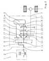
- Fig. 1is a vehicle drive train 1 with a prime mover 2, a transmission device 3 and an output 4 shown in a highly schematic.
- the transmission device 3is designed with a variator 5 configured as a hydrostatic device for steplessly varying a ratio of the transmission device 3.
- a torque provided by the drive machine 2is introduced into the transmission device 3 in the region of a transmission input 6 and directed out of the transmission device 3 in the direction of the drive 4 in the region of a transmission output 7.
- the torque applied in the region of the transmission input 6is introduced into a planetary gear device 8 via a first shaft 9, which is embodied here as a planetary web.
- a so-called power branching of the torque of the engine 2is performed, wherein a portion of the torque is divided over a presently formed as a ring gear second shaft 10 of the planetary gear device 8 and designed as a sun gear third shaft 11 of the planetary gear device 8.
- the second shaft 10 of the planetary gear device 8is coupled to a first shaft 12 of the variator 5 and the third shaft 11 of the planetary gear device 8 is coupled to a second shaft 13 of the variator 5.
- the transmission device 3 with two switching elements 14, 15is formed.
- the ratio of the transmission device 3 via the variator 5is continuously variable, wherein the ring gear 10 of the planetary gear device 8 via the first switching element 14 with a rotatable on the second shaft 13th the variator 5 arranged idler gear 16 is connectable.
- the second switching element 15the third wave or the sun gear of the planetary gear device 8 with the idler gear 16 rotatably connected.
- the idler gear 16meshes with a non-rotatably connected to a countershaft 17 gear 18, which in turn is in operative connection with the transmission output 7.
- the two via the switching elements 14 and 15 in the transmission device 3 insertable translation areasoverlap.
- the third shaft 11 of the planetary gear device 8is connected via the second switching element 15 to the transmission output 7, wherein during the Alternating between the transmission ranges, the ratio in the range of the variator 5 is set to a value at which the ring gear 10 and the sun gear 11 of the planetary gear device 8 rotate at the same speed.
- the switched switching element 14 or 15is transferred from its closed operating state to its open operating state, while the respective switched off switching element 15 or 14 is transferred from its open to its closed operating state, wherein when switching between the two switching elements 14 and 15 no speed difference is overcome.
- the variator 5 or the hydrostatic unitis designed with a pump and a motor in Schrägachsenbauart, which are positively coupled via a common pivot member and thus has a simple and inexpensive control over only one adjusting mechanism.
- a setting angle of the common pivoting part between the motor and the pump of the variator 5which is pivotable between 0 ° to about 45 °, the rotational speeds of the first shaft 12 and the second shaft 13 of the variator 5 change in the end positions of the pivoting part respectively between shaft standstill and maximum speed.
- the variatoris formed with independently adjustable units.
- the directions of rotation of the shafts 12 and 13 of the variator 5are such that during forward travel of the trained with the vehicle drive train 1 vehicle and a pivoting of the pivoting part of the variator 5 in the region of the two switching elements 14 and 15 of the synchronous ratio change required synchronous operation is adjustable, wherein the directions of rotation of the two shafts 12 and 13 of the variator 5 are basically in opposite directions.
- the transmission device 3is formed with a single, simple planetary gear and a variator 5, which is arranged in the manner described above between two shafts 10 and 11 of the planetary gear device 8, as large as possible, stepless driving range with synchronous switching between the two switching elements fourteenth and 15 to be able to represent.
- a start from the vehicle standstill power split feasiblewith the transmission device 3, a start from the vehicle standstill power split feasible.
- the pivoting part of the variator 5is pivoted such that the first shaft 12 of the variator 5 is blocked by variatorinterne states and the second shaft 13 of the variator 5 can rotate freely without power transmission, the countershaft 17 and the transmission output 7 with closed first switching element 14 are blocked and how downforce 4 stand still.
- the first shaft of the variator 12begins to rotate and the second shaft 13 of the variator 5 begins to absorb power.
- the torque applied via the ring gear 10 of the planetary gear device 8, which is now supported in the region of the variator 5is transmitted via the idler gear 16 and the gear 18 to the countershaft 17 and thus the transmission output 7, thus producing the output 4 or the vehicle running with the vehicle drive train 1 begins to roll.
- the first switching element 14remains closed in the entire first gear range or driving range of the transmission device 3.
- an increasing displacement angle of the swiveling part of the variator 5 during the starting process of the vehiclecauses a translation with the value in the area of the planetary gear device 8 between the sun gear 11 and the ring gear 10 in a predefined operating point of the variator 5 +1.
- the ring gear 10 and the sun gear 11then have the same speed and the planetary gear device 8 circulates in the block.
- a switching between the two switching elements 14 and 15 without speed differencecan be carried out.
- the transmission device 10is provided between the first shaft 10 of the planetary gear device 8 or the ring gear and the first shaft 12 of the variator 5.
- the transmission device 10is a high ratio between the first shaft 12 of the variator 5 and the ring gear 10 of the planetary gear device 8 can be displayed, which by the arrangement of the transmission device 19, the synchronization point in the region of the two switching elements 14 and 15 only at a displacement angle of the pivot member significantly larger than half the total swing angle is reached.
- the pivot angle of the variator 5is reduced to increase the output shaft speed or the rotational speed of the countershaft 17.
- the highest speed of the countershaft 17 and the transmission output 7is achieved when the ring gear 10 of the planetary gear device 8 is blocked by the variator 5 when the second switching element 15 is closed.
- the sun gear 11 of the planetary gear device 8is driven without power transmission in the region of the variator 5, since the entire torque of the drive machine 2 is guided via the second switching element 15 in the direction of the output 4.
- the transmission device 3is to be executed in a manner not shown with a device by means of which the hydraulic conveying direction in the range of the variator 5 switchable with the vehicle stationary is. It is conceivable that the hydraulic circuit of the variator 5 with one of the DE 10 2006 025 348 A1 known valve device is executed.
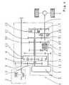
- a second embodiment of the transmission device 3is shown, which differs from the in Fig. 1 illustrated embodiment in the area between the sun gear 11 of the planetary gear device 8 and the transmission output 7 by further sets of wheels 20 to 20n and these respective associated switching elements 21 to 21 n differs to provide additional translation areas available that can be inserted by powershifting in the transmission device 3.
- the reference numeral 20 and 21 each trailing letter nis in each case representative of the arbitrary integer number of additional gear pairs and switching elements of the transmission device 3, which varies depending on the particular application.
- the transmission device 3is to be designed with additional gear ratios when a vehicle running with the vehicle drivetrain 1 is to be operated at higher end speeds.
- gear changes in the transmission device 3 between the first switching element 14 or the second switching element 15 and the third switching element 21 and the other switching elements 21 n only in non-synchronous operating state of the transmission device 3can be carried out. Nevertheless, when changing between the first transmission range or the second transmission range and the third or the nth transmission range, it is possible to reduce the speed difference to be bridged by adjusting the ratio of the variator 5 during the switching process.
- the ring gear 10 of the planetary gear device 8in addition to the first switching element 14 and the idler gear 16 and the gear 18 via a further switching element 22 with the countershaft 17 can be brought into operative connection.
- a rotatably mounted on the sun gear 11 of the planetary gear device 8 idler gear 23 via the other switching element 22 rotationally fixed to the Ring gear 10 of the planetary gear device 9connectable.
- the idler gear 23meshes with an intermediate gear 24, which in turn is in engagement with a fixed gear 25 of the countershaft 17.
- a wheel set with the intermediate gear 24 via the further switching element 22 between the ring gear 10 of the planetary gear device 8 and the transmission output 7 in power flow of the transmission device 3can be switched.
- the switching between the first switching element 14, the second switching element 15 or the additional switching element 21 and the further switching element 22is carried out in each case at low rotational speeds of the output 4 or at standstill of the output 4.
- the circuitseach represent reversing circuits, by means of which in each case a reverse drive of one with the vehicle drive train 1 according to Fig. 3 running vehicle is made possible.
- a idler gear 26 rotatably connected to the sun gear 11 of the planetary gear device 8, which meshes with another fixed gear 27 of the countershaft and no integral unit with the idler gear 16is formed.
- a fourth and a fifth embodiment of the transmission device 3are shown, which basically have the same structure and from the in Fig. 1 to Fig. 3 illustrated embodiments of the transmission device 3 differ in that with the transmission devices 3 according to Fig. 4 and Fig. 5 two synchronous area changes can be performed in each case.
- the transmission devices 3 according to Fig. 4 and Fig. 5executed with the two switching elements 14 and 15 and with a third switching element 28.
- the second shaft or the ring gear 10 of the planetary gear device 8is connected in the closed state of the first switching element 14 to the transmission output 7, wherein a rotatably mounted on the countershaft 17 idler gear 29, which rotatably with the Ring gear 10 operatively connected fixed gear 30 meshes, in the closed state of the first switching element 14 rotatably connected to the countershaft 17 is connected.
- the variator 5is adjusted to its first extreme position in which the speed of the first shaft 12 of the Variator 5, which is connected to a motor device of the variator 5, equal to zero.
- the connected via the transmission device 19 with the first shaft 12 of the variator 5 ring gear 10is also stationary in this operating condition. If there is a corresponding requirement for a starting operation of the vehicle drive train 1 formed vehicle, the variator 5 is pivoted from the latter first extreme position via a preferably common yoke and the speed or the engine speed of the engine of the variator increases. This simultaneously leads to the speed of the output 4 of the vehicle running with the transmission device 3 increasing and the vehicle being started up.
- the variator 5For continuously increasing the vehicle speed, the variator 5 is moved from its first extreme position to its second extreme position, and the first transmission region of the transmission device 3 is steplessly passed completely through.
- the speed of the motor of the variator 5increases increasingly in the direction of its maximum value, while the speed of the Pump of the variator is lowered from its maximum value to zero.
- the second extreme position of the variator 5In the second extreme position of the variator 5 is in the range of the second switching element 15, the synchronization point, whereby the second switching element 15 can be converted without rotational speed difference in its closed operating state, while the first switching element 14 is opened.
- the third switching element 28is arranged on the countershaft 7 to a rotatably mounted on the countershaft 7 idler gear 31 which meshes with a rotatably connected to the ring gear 10 fixed gear 32, in the closed state against rotation with the countershaft 7 connect.
- the third switching element 28 on the second shaft 13 of the Variator 5is arranged and connects a rotatably mounted on the second shaft 13 of the variator 5 idler gear 33 in the closed state with the ring gear 10 of the planetary gear device 8.
- the idler gear 33meshes with a non-rotatably connected to the countershaft 17 fixed gear 34, whereby an operative connection between the ring gear 10 and the transmission output 7 is given in the closed state of the third switching element 28.
- Both with the transmission device 3 according to Fig. 4 as well as with the transmission device 3 according to Fig. 5are each two synchronous area change with a cost-effectively manufacturable and structurally simple planetary gear set with only two output shafts displayed.
- the fourth and the fifth embodiment of the transmission device 3each one opposite to in Fig. 1 to Fig. 3 illustrated embodiments of the transmission device 3 extended system, wherein, depending on the particular application, one or two synchronous area changes are feasible when the transmission device 3 has the necessary structure.
- the transmission device 3 for implementing a modular principleis ideally designed such that depending on the requirement for a two- or three-speed transmission with one or two synchronous range changes, the third switching element 28 is provided or the transmission device 3 is performed without the third switching element 28.
- the switching elements 14, 15, 21 to 21 n, 22 and 28 of the embodiments of the transmission device 3 shown in the drawingare all designed as frictional multi-plate clutches or frictional shift elements to represent the to be carried out in the transmission device 3 change between the transmission ranges without interruption of traction can ,
- the transmission device according to the inventionis deviating from the embodiments shown in the drawing and explained in more detail in the above description also executable with other variators, via which the transmission of power from the drive machine 2 in the direction of the output 4 is continuously transferable and variable.
- the transmission device 3 according to the inventioncan also be implemented with other suitable embodiments of a variator, such as a looping variator, a Reibradvariator, two cooperatively connected electric motors and the like, wherein in the field of agricultural machinery, the execution of a variator is preferred as Hydrostat issued this variant has the highest power density.
Landscapes
- Engineering & Computer Science (AREA)
- General Engineering & Computer Science (AREA)
- Mechanical Engineering (AREA)
- Transmission Devices (AREA)
Abstract
Description
Translated fromGermanDie Erfindung betrifft eine Getriebevorrichtung mit einem Variator zum stufenlosen Variieren einer Übersetzung und mit sekundärer Leistungsverzweigung gemäß der im Oberbegriff des Patentanspruches 1 näher definierten Art.The invention relates to a transmission device with a variator for stepless variation of a transmission and secondary power split according to the closer defined in the preamble of
Die
Aus der
Zusätzlich ist die zweite Welle des Variators mit mehreren Festrädern ausgeführt, welche mit mehreren auf einer Vorgelegewelle angeordneten Losrädern kämmen, wobei die Losräder zur Darstellung verschiedener Fahrbereiche bzw. Übersetzungsbereiche für Vorwärtsfahrt und wenigstens eines Fahrbereiches für Rückwärtsfahrt über Schaltelemente drehfest mit der Vorgelegewelle verbindbar sind.In addition, the second shaft of the variator is designed with several fixed wheels, which mesh with several arranged on a countershaft idler gears, the idler gears for displaying different driving ranges or transmission ranges for forward travel and at least one driving range for reverse drive via switching elements rotatably connected to the countershaft.
Die Wechsel zwischen den Fahrbereichen sind nachteilhafterweise nicht synchron durchführbar, womit zur Vermeidung einer Unterbrechung der Zugkraft auf jeden Fall während eines Fahrbereichswechsels eine Lastschaltung mit einer Korrektur der Übersetzung im Bereich der Hydrostateinrichtung durchzuführen ist. Während solcher Schaltungen treten unter Umständen unerwünschterweise einen Arbeitsablauf einer mit dem vorbeschriebenen Leistungsverzweigungsgetriebe ausgeführten Arbeitsmaschine störende Reaktionsmomente im Antriebsstrang einer Arbeitsmaschine auf, die im Betrieb von einer Bedienperson der Arbeitsmaschine als Ruck wahrnehmbar sind.The changes between the driving ranges are disadvantageously not synchronously feasible, which in any case during a driving range change a load circuit to avoid interruption of the traction to be performed with a correction of the translation in the area of the hydrostatic device. During such circuits may undesirably occur a workflow with the above-described power split transmission Running machine annoying reaction moments in the drive train of a work machine, which are perceptible in operation by an operator of the machine as a jerk.
Der vorliegenden Erfindung liegt daher die Aufgabe zu Grunde, eine Getriebevorrichtung zur Verfügung zu stellen, mittels welchem in kritischen Betriebszuständen einer Arbeitsmaschine synchrone Fahrbereichswechsel durchführbar sind und das einen konstruktiv einfachen Aufbau aufweist.The present invention is therefore based on the object to provide a transmission device available by means of which in synchronous operating conditions of a work machine synchronous driving range change can be carried out and has a structurally simple structure.
Erfindungsgemäß wird diese Aufgabe mit einer Getriebevorrichtung mit den Merkmalen des Patentanspruches 1 gelöst.According to the invention this object is achieved with a transmission device having the features of
Die erfindungsgemäße Getriebevorrichtung ist mit einem Variator zum stufenlosen Variieren einer Übersetzung und mit sekundärer Leistungsverzweigung ausgebildet, wobei eine Plantetengetriebeeinrichtung zur Leistungsverzweigung vorgesehen ist. Eine erste Welle der Plantetengetriebeeinrichtung ist mit dem Getriebeeingang, eine zweite Welle der Planetengetriebeeinrichtung ist mit einer ersten Welle des Variators und eine dritte Welle der Plantetengetriebeeinrichtung ist mit einer zweiten Welle des Variators gekoppelt. Darüber hinaus sind wenigstens ein erstes Schaltelement und ein zweites Schaltelement zum Umschalten zwischen einem ersten Übersetzungsbereich und einem zweiten Übersetzungsbereich vorgesehen, innerhalb welchen die Übersetzung über den Variator jeweils stufenlos veränderbar ist.The transmission device according to the invention is formed with a variator for infinitely variable transmission and secondary power split, wherein a planetary gear device is provided for power branching. A first shaft of the planetary gear device is connected to the transmission input, a second shaft of the planetary gear device is coupled to a first shaft of the variator and a third shaft of the planetary gear device is coupled to a second shaft of the variator. In addition, at least a first switching element and a second switching element are provided for switching between a first gear range and a second gear range, within which the translation via the variator is in each case continuously variable.
Erfindungsgemäß überlappen sich die beiden Übersetzungsbereiche und die zweite Welle des Plantetenradsatzes ist zur Darstellung des ersten Übersetzungsbereiches über das erste Schaltelement mit dem Getriebeausgang und die dritte Welle der Planetengetriebeeinrichtung ist zur Darstellung des zweiten Übersetzungsbereiches über das zweite Schaltelement mit dem Getriebeausgang verbindbar.According to the invention, the two translation regions overlap and the second shaft of the planetary gearset is for displaying the first gear range via the first switching element with the transmission output and the third shaft of the planetary gear device is connectable to the representation of the second transmission range via the second switching element with the transmission output.
Bei der Getriebevorrichtung nach der Erfindung ist über eine geeignete Betätigung des Variators zwischen der zweiten Welle und der dritten Welle der Planetengetriebeeinrichtung die Übersetzung +1 darstellbar, so dass dieser im Block umläuft und eine Umschaltung zwischen dem ersten Schaltelement und dem zweiten Schaltelement ohne Drehzahldifferenz durchführbar ist. Das bedeutet, dass die Umschaltung zwischen dem ersten Fahrbereich und dem zweiten Fahrbereich in der Getriebevorrichtung synchron und ohne Beeinträchtigung eines Arbeitsablaufes einer mit der erfindungsgemäßen Getriebevorrichtung ausgeführten Arbeitsmaschine darstellbar ist.In the transmission device according to the invention is via a suitable actuation of the variator between the second shaft and the third shaft of the planetary gear device, the ratio +1 representable, so that it rotates in the block and a switch between the first switching element and the second switching element without speed difference is feasible , This means that the changeover between the first travel range and the second drive range in the transmission device can be represented synchronously and without impairment of a work process of a work machine embodied with the transmission device according to the invention.
Darüber hinaus ist ein Anfahren einer Arbeitsmaschine aus dem Stillstand leistungsverzweigt möglich, wodurch eine Belastung des Variators auf einfache Art und Weise im Vergleich zu aus der Praxis bekannten Getriebeeinrichtungen, bei welchen ein Anfahrmoment während des Anfahrens einer Arbeitsmaschine vollständig über den Variator geführt wird, reduziert ist.In addition, starting a work machine from a standstill power split is possible, whereby a load on the variator in a simple manner compared to known from practice transmission devices, in which a starting torque is performed during the startup of a work machine completely over the variator, is reduced ,
Zudem weist die Getriebevorrichtung nach der Erfindung, das mit einem einzigen, einfachen Planetengetriebe und einem Variator ausgeführt ist, einen konstruktiv einfachen Aufbau sowie eine geringe Bauteilanzahl auf, so dass die Getriebevorrichtung mit geringem Aufwand montierbar ist, kostengünstig herstellbar ist und durch einen geringen Bauraumbedarf gekennzeichnet ist.In addition, the transmission device according to the invention, which is designed with a single, simple planetary gear and a variator, a structurally simple structure and a low number of components, so that the transmission device can be mounted with little effort, is inexpensive to produce and characterized by a low space requirement is.
Eine vorteilhafte und durch eine kompakte Bauart gekennzeichnete Weiterbildung der Getriebevorrichtung ist mit einer zur zweiten Welle des Variators parallel angeordneten Vorgelegewelle ausgeführt, die mit dem Getriebeausgang in Wirkverbindung steht.An advantageous and characterized by a compact design development of the transmission device is designed with a parallel to the second shaft of the variator countershaft, which is in operative connection with the transmission output.
Über die beiden Schaltelemente ist bei einer weiteren durch eine geringe Bauteilanzahl gekennzeichnete Ausführungsform der erfindungsgemäßen Getriebevorrichtung jeweils wenigstens ein Losrad drehfest mit der zweiten Welle des Variators und der dritten Welle der Planetengetriebeeinheit verbindbar, welches wiederum mit einem Zahnrad der Vorgelegewelle wirkverbunden ist.In the case of a further embodiment of the transmission device according to the invention characterized by a small number of components, at least one idler gear is in each case non-rotatable with the second shaft via the two shifting elements the variator and the third shaft of the planetary gear unit connectable, which in turn is operatively connected to a gear of the countershaft.
Bei einer ebenfalls durch einen einfachen Aufbau gekennzeichneten und eine kompakte Bauart aufweisenden Ausführungsform der erfindungsgemäßen Getriebevorrichtung sind die beiden Schaltelemente auf der dritten Welle der Planetengetriebeeinrichtung oder der zweiten Welle des Variators angeordnet.In a likewise characterized by a simple structure and having a compact design embodiment of the transmission device according to the invention, the two switching elements are arranged on the third shaft of the planetary gear device or the second shaft of the variator.
Um eine Belastung des Variators auf konstruktiv einfache und kostengünstige Art und Weise zu reduzieren und die über die Getriebevorrichtung nach der Erfindung übertragbare Leistung im Vergleich zu herkömmlich ausgebildeten Getriebevorrichtungen steigern zu können, ist die zweite Welle der Planetengetriebeeinrichtung bei einer Ausführungsform der Getriebevorrichtung über eine Getriebeeinrichtung mit der ersten Welle des Variators wirkverbunden, über die zwischen der ersten Welle des Variators und der zweiten Welle der Planetengetriebeeinrichtung eine hohe Übersetzung darstellbar ist.In order to reduce a load on the variator in a structurally simple and cost-effective manner and to be able to increase the transmittable over the transmission device according to the invention compared to conventionally designed transmission devices, the second shaft of the planetary gear device in one embodiment of the transmission device via a transmission device with operatively connected to the first shaft of the variator over which a high ratio can be displayed between the first shaft of the variator and the second shaft of the planetary gear device.
Bei einer weiteren vorteilhaften Ausführungsform der erfindungsgemäßen Getriebevorrichtung ist eine Drehrichtungsumkehr zwischen dem Getriebeeingang und dem Getriebeausgang mittels einer Ventileinrichtung eines hydraulischen Kreislaufes des als Hydrostateinrichtung ausgebildeten Variators darstellbar, über welche eine Förderrichtung im hydraulischen Kreislauf umschaltbar ist.In a further advantageous embodiment of the transmission device according to the invention a reversal of direction between the transmission input and the transmission output by means of a valve device of a hydraulic circuit of the designed as a hydrostatic variator can be displayed, via which a conveying direction in the hydraulic circuit can be switched.
Zur Darstellung weiterer Übersetzungsbereiche ist eine weitere Ausführungsform der Getriebevorrichtung nach der Erfindung zwischen der dritten Welle der Planetengetriebeeinrichtung und dem Getriebeausgang mit mehreren über weitere Schaltelemente zuschaltbaren Zahnradpaarungen ausgebildet, wobei bei einer Weiterbildung der Getriebevorrichtung wenigstens eine der Zahnradpaarungen mit einem Zwischenrad zur Darstellung einer Drehrichtungsumkehr zwischen dem Getriebeeingang und dem Getriebeausgang ausgeführt ist.To illustrate further translation ranges, another embodiment of the transmission device according to the invention is formed between the third shaft of the planetary gear device and the transmission output with a plurality of gear pairs engageable via further switching elements, wherein in a further development of the transmission device at least one of the gear pairings with an intermediate wheel to represent a reversal of direction between the transmission input and the transmission output is executed.
Eine weitere vorteilhafte Ausführungsform der erfindungsgemäßen Getriebevorrichtung ist mit einem dritten Schaltelement ausgebildet, über welches zur Darstellung eines dritten Übersetzungsbereiches, der sich mit dem zweiten Übersetzungsbereich überlappt, die zweite Welle der Planetengetriebeeinrichtung mit dem Getriebeausgang koppelbar ist. Damit ist sowohl der Bereichswechsel zwischen dem ersten und dem zweiten Übersetzungsbereich als auch der Bereichswechsel zwischen dem zweiten Übersetzungsbereich und dem dritten Übersetzungsbereich der erfindungsgemäßen Getriebevorrichtung synchron, d. h. ohne Differenzdrehzahlen im Bereich des ersten Schaltelementes und des zweiten Schaltelementes bzw. zwischen dem zweiten Schaltelement und dem dritten Schaltelement, mit einem kostengünstig herstellbaren und konstruktiv einfach ausgeführten Planetenradsatz mit lediglich zwei Abtriebswellen durchführbar.A further advantageous embodiment of the transmission device according to the invention is formed with a third switching element, via which the second shaft of the planetary gear device can be coupled to the transmission output in order to display a third transmission range which overlaps with the second transmission range. Thus, both the range change between the first and the second transmission range and the range change between the second transmission range and the third transmission range of the transmission device according to the invention are synchronous, d. H. without differential speeds in the region of the first switching element and the second switching element or between the second switching element and the third switching element, with a cost-effectively manufacturable and structurally simple planetary gear with only two output shafts feasible.
Damit besteht auch auf einfache Art und Weise in Abhängigkeit des jeweils vorliegenden Anwendungsfalles die Möglichkeit, ein sogenanntes Baukastenprinzip zu verwirklichen und die erfindungsgemäße Getriebevorrichtung zur Darstellung eines synchronen Bereichswechsels lediglich mit dem ersten und dem zweiten Schaltelement auszuführen und die Getriebevorrichtung zur Darstellung von zwei synchronen Bereichswechseln zusätzlich mit dem dritten Schaltelement auszubilden, ohne den grundsätzlichen Aufbau der Getriebevorrichtung ändern zu müssen.This is also in a simple manner depending on the particular application, the possibility to realize a so-called modular principle and perform the transmission device according to the invention for displaying a synchronous area change only with the first and the second switching element and the transmission device for displaying two synchronous range changes additionally form with the third switching element, without having to change the basic structure of the transmission device.
Das bedeutet, dass die Getriebevorrichtung nach der Erfindung in Abhängigkeit der Anforderung, ob mit der Getriebevorrichtung ein oder zwei synchrone Bereichswechsel durchzuführen sind, mit dem dritten Schaltelement ausgebildet wird oder nicht, wobei die jeweilige Ausführung bei besonders kostengünstigen Lösungen ohne aufwändige konstruktive Änderungen des grundsätzlichen Aufbaus der Getriebevorrichtung realisierbar ist.This means that the transmission device according to the invention, depending on the requirement whether or not one or two synchronous range changes are to be performed with the transmission device, is formed with the third switching element or not, the respective embodiment being particularly advantageous cost-effective solutions without complex structural changes of the basic structure of the transmission device can be realized.
Um einen angeforderten Wechsel zwischen den Übersetzungsbereichen der erfindungsgemäßen Getriebevorrichtung als Lastschaltung ausführen zu können, sind die Schaltelemente bei einer weiteren vorteilhaften Ausführungsform der Getriebevorrichtung als reibschlüssige Lastschaltelemente ausgebildet.In order to perform a requested change between the transmission ranges of the transmission device according to the invention as a load circuit, the switching elements are formed in a further advantageous embodiment of the transmission device as frictional load switching elements.
Weitere Vorteile und vorteilhafte Weiterbildungen der Erfindung ergeben sich aus den Patentansprüchen und den unter Bezugnahme auf die Zeichnung prinzipmäßig beschriebenen Ausführungsbeispielen, wobei zu Gunsten der Übersichtlichkeit in der Beschreibung der Ausführungsbeispiele für bau- und funktionsgleiche Bauteile dieselben Bezugszeichen verwendet werden.Further advantages and advantageous developments of the invention will become apparent from the claims and the embodiments described in principle with reference to the drawings, wherein the same reference numerals are used in favor of clarity in the description of the embodiments for components identical in construction and function.
Es zeigt:
- Fig. 1
- eine stark schematisierte Darstellung eines Fahrzeugantriebsstranges mit einem Räderschema eines ersten Ausführungsbeispieles der Getriebevorrichtung nach der Erfindung;
- Fig. 2
- einen Fahrzeugantriebsstrang mit einem zweiten Ausführungsbeispiel der erfindungsgemäßen Getriebevorrichtung;
- Fig. 3
- einen Fahrzeugantriebsstrang mit einer dritten Ausführungsform der erfindungsgemäßen Getriebevorrichtung;
- Fig. 4
- einen Fahrzeugantriebsstrang mit einer vierten Ausführungsform der erfindungsgemäßen Getriebevorrichtung; und
- Fig. 5
- einen Fahrzeugantriebsstrang mit einer fünften Ausführungsform der erfindungsgemäßen Getriebevorrichtung.
- Fig. 1
- a highly schematic representation of a vehicle drive train with a wheel scheme of a first embodiment of the transmission device according to the invention;
- Fig. 2
- a vehicle drive train with a second embodiment of the transmission device according to the invention;
- Fig. 3
- a vehicle drive train with a third embodiment of the transmission device according to the invention;
- Fig. 4
- a vehicle drive train with a fourth embodiment of the transmission device according to the invention; and
- Fig. 5
- a vehicle drive train with a fifth embodiment of the transmission device according to the invention.
In
Getriebeeingangsseitig wird das im Bereich des Getriebeeingangs 6 anliegende Drehmoment in eine Planetengetriebeeinrichtung 8 über eine vorliegend als Planetensteg ausgeführte erste Welle 9 eingeleitet. Im Bereich der Planetengetriebeeinrichtung 8 wird eine so genannte Leistungsverzweigung des Drehmomentes der Antriebsmaschine 2 durchgeführt, wobei ein Teil des Drehmomentes über eine vorliegend als Hohlrad ausgebildete zweite Welle 10 der Planetengetriebeeinrichtung 8 und eine als Sonnenrad ausgeführte dritte Welle 11 der Planetengetriebeeinrichtung 8 aufgeteilt wird. Die zweite Welle 10 der Planetengetriebeeinrichtung 8 ist mit einer ersten Welle 12 des Variators 5 und die dritte Welle 11 der Planetengetriebeeinrichtung 8 ist mit einer zweiten Welle 13 des Variators 5 gekoppelt.At the transmission input side, the torque applied in the region of the
Zum Umschalten zwischen einem ersten Übersetzungsbereich und einem zweiten Übersetzungsbereich ist die Getriebevorrichtung 3 mit zwei Schaltelementen 14, 15 ausgebildet. Innerhalb der beiden Übersetzungsbereiche ist die Übersetzung der Getriebevorrichtung 3 über den Variator 5 jeweils stufenlos veränderbar, wobei das Hohlrad 10 der Planetengetriebeeinrichtung 8 über das erste Schaltelement 14 mit einem drehbar auf der zweiten Welle 13 des Variators 5 angeordneten Losrad 16 verbindbar ist. Über das zweite Schaltelement 15 ist die dritte Welle bzw. das Sonnenrad der Planetengetriebeeinrichtung 8 mit dem Losrad 16 drehfest verbindbar. Das Losrad 16 kämmt mit einem drehfest mit einer Vorgelegewelle 17 verbundenen Zahnrad 18, die wiederum mit dem Getriebeausgang 7 in Wirkverbindung steht.For switching between a first transmission range and a second transmission range, the
Zwischen dem Hohlrad 10 der Planetengetriebeeinrichtung 8 und der ersten Welle 12 des Variators 5 ist eine vorliegend als Stirnradverzahnung ausgeführte Getriebeeinrichtung 19 vorgesehen, mittels welcher das vom Hohlrad 10 der Planetengetriebeeinrichtung 8 in Richtung des Variators 5 geführte Drehmoment reduziert und die Drehzahl der ersten Welle 12 des Variators 5 gegenüber der Drehzahl des Hohlrades 10 angehoben wird.Between the
Die beiden über die Schaltelemente 14 und 15 in der Getriebevorrichtung 3 einlegbaren Übersetzungsbereiche überlappen sich. Zur Darstellung des ersten Übersetzungsbereiches wird die zweite Welle 10 der Planetengetriebeeinrichtung 8 über das erste Schaltelement 14 mit dem Getriebeausgang 7 und zur Darstellung des zweiten Übersetzungsbereiches wird die dritte Welle 11 der Planetengetriebeeinrichtung 8 über das zweite Schaltelement 15 mit dem Getriebeausgang 7 verbunden, wobei während des Wechsels zwischen den Übersetzungsbereichen die Übersetzung im Bereich des Variators 5 auf einen Wert eingestellt wird, zu dem das Hohlrad 10 und das Sonnenrad 11 der Planetengetriebeeinrichtung 8 mit der selben Drehzahl umlaufen.The two via the
In diesem Synchronpunkt der Getriebevorrichtung 3 wird dann jeweils das zugeschaltete Schaltelement 14 oder 15 aus seinem geschlossenen Betriebszustand in seinen geöffneten Betriebszustand überführt, während das jeweils abgeschaltete Schaltelement 15 oder 14 aus seinem geöffneten in seinen geschlossenen Betriebszustand überführt wird, wobei beim Umschalten zwischen den beiden Schaltelementen 14 und 15 keine Drehzahldifferenz zu überwinden ist.In this synchronous point of the
Der Variator 5 bzw. die Hydrostateinheit ist mit einer Pumpe und einem Motor in Schrägachsenbauart ausgeführt, die über ein gemeinsames Schwenkteil zwangsgekoppelt sind und weist somit eine einfache sowie kostengünstige Ansteuerung über nur einen Verstellmechanismus auf. In Abhängigkeit eines Stellwinkels des gemeinsamen Schwenkteiles zwischen dem Motor und der Pumpe des Variators 5, welches zwischen 0° bis ca. 45 ° verschwenkbar ist, wechseln die Drehzahlen der ersten Welle 12 und der zweiten Welle 13 des Variators 5 in den Endlagen des Schwenkteils jeweils zwischen Wellenstillstand und maximaler Drehzahl.The
In Abhängigkeit des jeweils vorliegenden Anwendungsfalles besteht jedoch auch die Möglichkeit, dass der Variator mit voneinander unabhängig einstellbaren Einheiten ausgebildet ist.Depending on the respective application, however, there is also the possibility that the variator is formed with independently adjustable units.
Grundsätzlich sind die Drehrichtungen der Wellen 12 und 13 des Variators 5 derart, dass bei Vorwärtsfahrt des mit dem Fahrzeugantriebsstrang 1 ausgebildeten Fahrzeuges und einer Verschwenkung des Schwenkteils des Variators 5 im Bereich der beiden Schaltelemente 14 und 15 der für den synchronen Übersetzungswechsel erforderliche Synchronlauf einstellbar ist, wobei die Drehrichtungen der beiden Wellen 12 und 13 des Variators 5 grundsätzlich gegensinnig sind.Basically, the directions of rotation of the
Die Getriebevorrichtung 3 ist mit einem einzigen, einfachen Planetengetriebe und einem Variator 5 ausgebildet, der in der vorbeschriebenen Art und Weise zwischen zwei Wellen 10 und 11 der Planetengetriebeeinrichtung 8 angeordnet ist, um einen möglichst großen, stufenlosen Fahrbereich bei synchroner Umschaltung zwischen den beiden Schaltelementen 14 und 15 darstellen zu können. Darüber hinaus ist mit der Getriebevorrichtung 3 ein Anfahren aus dem Fahrzeugstillstand leistungsverzweigt durchführbar.The
Im Fahrzeugstillstand wird das Schwenkteil des Variators 5 derart verschwenkt, dass die erste Welle 12 des Variators 5 durch variatorinterne Zustände blockiert ist und die zweite Welle 13 des Variators 5 ohne Leistungsübertragung frei drehen kann, wobei die Vorgelegewelle 17 sowie der Getriebeausgang 7 bei geschlossenem ersten Schaltelement 14 blockiert sind und wie Abtrieb 4 stillstehen.In vehicle standstill, the pivoting part of the
Wird das Schwenkteil des Variators 5 aus der vorgenannten Stellung verschwenkt, beginnt die erste Welle des Variators 12 zu drehen und die zweite Welle 13 des Variators 5 beginnt Leistung aufzunehmen. Im Bereich des ersten Schaltelementes 14 wird das über das Hohlrad 10 der Planetengetriebeeinrichtung 8 anliegende Drehmoment, welches nunmehr im Bereich des Variators 5 abgestützt wird, über das Losrad 16 und das Zahnrad 18 auf die Vorgelegewelle 17 und somit den Getriebeausgang 7 übertragen, womit der Abtrieb 4 bzw. das mit dem Fahrzeugantriebsstrang 1 ausgeführte Fahrzeug zu rollen beginnt. Das erste Schaltelement 14 bleibt im gesamten ersten Übersetzungsbereich bzw. Fahrbereich der Getriebevorrichtung 3 geschlossen.If the pivoting part of the
Ausgehend von letztbeschriebenem Betriebszustand der Getriebevorrichtung 3 führt ein zunehmender Verstellwinkel des Schwenkteils des Variators 5 während des Anfahrvorganges des Fahrzeuges dazu, dass sich im Bereich der Planetengetriebeeinrichtung 8 zwischen dem Sonnenrad 11 und dem Hohlrad 10 in einem vordefinierten Betriebspunkt des Variators 5 eine Übersetzung mit dem Wert +1 einstellt. Das Hohlrad 10 und das Sonnenrad 11 weisen dann dieselbe Drehzahl auf und die Planetengetriebeeinrichtung 8 läuft im Block um. In diesem Betriebszustand der Getriebevorrichtung 3 ist eine Umschaltung zwischen den beiden Schaltelemente 14 und 15 ohne Drehzahldifferenz durchführbar.Starting from the last-described operating state of the
Damit der Verstellbereich des Variators 5 im ersten Übersetzungsbereich und im zweiten Übersetzungsbereich möglichst mehrfach ausnutzbar ist und um die über die Getriebevorrichtung 3 übertragbare Leistung auf konstruktiv einfache Art und Weise steigern zu können, ist zwischen der ersten Welle 10 der Planetengetriebeeinrichtung 8 bzw. dem Hohlrad und der ersten Welle 12 des Variators 5 die Getriebeeinrichtung 10 vorgesehen. Mittels der Getriebeeinrichtung 10 ist eine hohe Übersetzung zwischen der ersten Welle 12 des Variators 5 und dem Hohlrad 10 der Planetengetriebeeinrichtung 8 darstellbar, womit durch die Anordnung der Getriebeeinrichtung 19 der Synchronpunkt im Bereich der beiden Schaltelemente 14 und 15 erst bei einem Verstellwinkel des Schwenkteiles deutlich größer als der halbe Gesamtschwenkwinkel erreicht wird.Thus, the adjustment of the
Nach dem Umschalten vom ersten Schaltelement 14 in Richtung des zweiten Schaltelementes 15 wird der Schwenkwinkel des Variators 5 zur Steigerung der Abtriebswellendrehzahl bzw. der Drehzahl der Vorgelegewelle 17 reduziert. Die höchste Drehzahl der Vorgelegewelle 17 bzw. des Getriebeausgangs 7 wird erreicht, wenn bei geschlossenem zweitem Schaltelement 15 das Hohlrad 10 der Planetengetriebeeinrichtung 8 durch den Variator 5 blockiert ist. In diesem Betriebszustand der Getriebevorrichtung 3 wird das Sonnenrad 11 der Planetengetriebeeinrichtung 8 ohne Leistungsübertragung im Bereich des Variators 5 angetrieben, da das gesamte Drehmoment der Antriebsmaschine 2 über das zweite Schaltelement 15 in Richtung des Abtriebs 4 geführt wird.After switching from the
Um mit der Getriebevorrichtung 3 auch einen Übersetzungsbereich für Rückwärtsfahrt ohne zusätzliche mechanische Bauteile zur Verfügung stellen zu können, ist die Getriebevorrichtung 3 in nicht näher dargestellter Art und Weise mit einer Einrichtung auszuführen, mittels welcher die hydraulische Förderrichtung im Bereich des Variators 5 bei stillstehendem Fahrzeug umschaltbar ist. Dabei ist es denkbar, dass der hydraulische Kreislauf des Variators 5 mit einer aus der
In
Grundsätzlich sind Übersetzungswechsel in der Getriebevorrichtung 3 zwischen dem ersten Schaltelement 14 oder dem zweiten Schaltelement 15 und dem dritten Schaltelement 21 bzw. den weiteren Schaltelementen 21 n nur in nicht synchronem Betriebszustand der Getriebevorrichtung 3 durchführbar. Dennoch besteht bei Wechseln zwischen dem ersten Übersetzungsbereich oder dem zweiten Übersetzungsbereich und dem dritten oder dem n-ten Übersetzungsbereich jeweils die Möglichkeit, während des Umschaltvorganges die zu überbrückende Drehzahldifferenz durch Anpassung der Übersetzung des Variators 5 zu reduzieren.Basically, gear changes in the
Bei dem in
Damit ist ein Radsatz mit dem Zwischenrad 24 über das weitere Schaltelement 22 zwischen dem Hohlrad 10 der Planetengetriebeeinrichtung 8 und dem Getriebeausgang 7 in Kraftfluss der Getriebevorrichtung 3 zuschaltbar. Die Umschaltung zwischen dem ersten Schaltelement 14, dem zweiten Schaltelement 15 oder dem zusätzlichen Schaltelement 21 und dem weiteren Schaltelement 22 wird jeweils bei kleinen Drehzahlen des Abtriebs 4 oder im Stillstand des Abtriebs 4 durchgeführt. Die Schaltungen stellen jeweils Reversierschaltungen dar, mittels welchen jeweils eine Rückwärtsfahrt eines mit dem Fahrzeugantriebsstrang 1 gemäß
Über das zweite Schaltelement 15 ist im Gegensatz zu den Ausführungsbespielen der Getriebevorrichtung 3 gemäß
In
Hierfür sind die Getriebevorrichtungen 3 gemäß
Ausgehend von einem Betriebszustand des Fahrzeugantriebsstranges 1, zu dem in der Getriebevorrichtung 3 über das geschlossene erste Schaltelement 14 der erste Übersetzungsbereich eingelegt ist und im Stillstand des Fahrzeuges, ist der Variator 5 in seine erste Extremstellung verstellt, in der die Drehzahl der ersten Welle 12 des Variators 5, welche mit einer Motoreinrichtung des Variators 5 verbunden ist, gleich Null ist. Das über die Getriebeeinrichtung 19 mit der ersten Welle 12 des Variators 5 verbundene Hohlrad 10 steht in diesem Betriebszustand ebenfalls still. Liegt eine entsprechende Anforderung für einen Anfahrvorgang des mit dem Fahrzeugantriebsstrang 1 ausgebildeten Fahrzeuges vor, wird der Variator 5 aus der letztgenannten ersten Extremstellung über ein vorzugsweise gemeinsames Joch verschwenkt und die Drehzahl bzw. die Motordrehzahl des Motors des Variators steigt an. Dies führt gleichzeitig dazu, dass die Drehzahl des Abtriebs 4 des mit der Getriebevorrichtung 3 ausgeführten Fahrzeuges ansteigt und das Fahrzeug angefahren wird.Starting from an operating state of the
Zur kontinuierlichen Steigerung der Fahrzeuggeschwindigkeit wird der Variator 5 von seiner ersten Extremstellung in seine zweite Extremstellung verstellt und der erste Übersetzungsbereich der Getriebevorrichtung 3 stufenlos vollständig durchfahren. Dabei steigt die Drehzahl des Motors des Variators 5 zunehmend in Richtung seines Maximalwertes an, während die Drehzahl der Pumpe des Variators von ihrem Maximalwert auf Null abgesenkt wird. In der zweiten Extremstellung des Variators 5 stellt sich im Bereich des zweiten Schaltelementes 15 der Synchronpunkt ein, womit das zweite Schaltelement 15 ohne Drehzahldifferenz in seinen geschlossenen Betriebszustand überführbar ist, während das erste Schaltelement 14 geöffnet wird.For continuously increasing the vehicle speed, the
Nach erfolgreichem synchronen Bereichswechsel vom ersten Übersetzungsbereich in den zweiten Übersetzungsbereich und bei Vorliegen einer weiteren Anforderung zur Steigerung der Fahrzeuggeschwindigkeit wird der Variator 5 ausgehend von seiner zweiten Extremstellung wiederum in Richtung seiner ersten Extremstellung verschwenkt. Dies führt dazu, dass die Drehzahl der zweiten Welle des Variators 13 ansteigt, während die Drehzahl des Hohlrades 10 reduziert wird.After successful synchronous range change from the first gear ratio in the second gear range and in the presence of a further request to increase the vehicle speed of the
Zu einem vordefinierten Verschwenkwinkel des Jochs des Variators 5, der in Abhängigkeit der Übersetzung der von dem Losrad 29 und dem Festrad 30 ausgebildeten Stirnradverzahnung steht, wird im Bereich des zweiten Schaltelementes 15 und im Bereich des dritten Schaltelementes 28 gleichzeitig der Synchronpunkt erreicht, womit ein zweiter synchroner Bereichswechsel zwischen dem zweiten Übersetzungsbereich und dem dritten Übersetzungsbereich in der Getriebevorrichtung 3 ohne Differenzdrehzahl zwischen dem zweiten Schaltelement 15 und dem dritten Schaltelement 28 durchführbar ist.At a predefined pivoting angle of the yoke of the
Bei der in
Bei dem in
Sowohl mit der Getriebevorrichtung 3 gemäß
Grundsätzlich stellen die vierte und die fünfte Ausführungsform der Getriebevorrichtung 3 jeweils ein gegenüber den in
In diesem Zusammenhang ist die Getriebevorrichtung 3 zur Realisierung eines Baukastenprinzips idealerweise derart auszuführen, dass in Abhängigkeit der Anforderung für ein Zwei- oder Dreiganggetriebe mit einem oder zwei synchronen Bereichswechseln das dritte Schaltelement 28 vorgesehen wird oder die Getriebevorrichtung 3 ohne das dritte Schaltelement 28 ausgeführt wird.In this context, the
Die Schaltelemente 14, 15, 21 bis 21 n, 22 und 28 der in der Zeichnung dargestellten Ausführungsbeispiele der Getriebevorrichtung 3 sind alle als reibschlüssige Lamellenkupplungen bzw. reibschlüssige Schaltelemente ausgeführt, um die in der Getriebevorrichtung 3 durchzuführenden Wechsel zwischen den Übersetzungsbereichen ohne Zugkraftunterbrechung darstellen zu können.The switching
Die erfindungsgemäße Getriebevorrichtung ist abweichend von den in der Zeichnung dargestellten und in der vorstehenden Beschreibung näher erläuterten Ausführungsbeispielen auch mit anderen Variatoren ausführbar, über welche die Übertragung der Leistung von der Antriebsmaschine 2 in Richtung des Abtriebs 4 stufenlos übertragbar und variierbar ist. Das bedeutet, dass die Getriebevorrichtung 3 nach der Erfindung auch mit anderen geeigneten Ausführungsformen eines Variators, wie einem Umschlingungsvariator, einem Reibradvariator, zwei miteinander wirkverbundenen Elektromotoren und dergleichen, ausführbar ist, wobei im Bereich von Landmaschinen die Ausführung eines Variators als Hydrostateinrichtung bevorzugt wird, da diese Variante die höchste Leistungsdichte aufweist.The transmission device according to the invention is deviating from the embodiments shown in the drawing and explained in more detail in the above description also executable with other variators, via which the transmission of power from the
- 11
- FahrzeugantriebsstrangVehicle powertrain
- 22
- Antriebsmaschineprime mover
- 33
- Getriebevorrichtungtransmission device
- 44
- Abtrieboutput
- 55
- Variatorvariator
- 66
- Getriebeeingangtransmission input
- 77
- Getriebeausgangtransmission output
- 88th
- PlanetengetriebeeinrichtungPlanetary gear set
- 99
- erste Welle der Planetengetriebeeinrichtungfirst shaft of the planetary gear device
- 1010
- zweite Welle der Planetengetriebeeinrichtungsecond shaft of the planetary gear device
- 1111
- dritte Welle der Planetengetriebeeinrichtungthird shaft of the planetary gear device
- 1212
- erste Welle des Variatorsfirst wave of the variator
- 1313
- zweite Welle des Variatorssecond shaft of the variator
- 1414
- erstes Schaltelementfirst switching element
- 1515
- zweites Schaltelementsecond switching element
- 1616
- LosradLosrad
- 1717
- VorgelegewelleCountershaft
- 1818
- Zahnradgear
- 1919
- Getriebeeinrichtungtransmission device
- 20 bis 20n20 to 20n
- Zahnradpaarunggear pair
- 21 bis 21n21 to 21n
- Schaltelementswitching element
- 2222
- weiteres Schaltelementanother switching element
- 2323
- LosradLosrad
- 2424
- Zwischenradidler
- 2525
- Zahnradgear
- 2626
- LosradLosrad
- 2727
- Festradfixed gear
- 2828
- drittes Schaltelementthird switching element
- 2929
- LosradLosrad
- 3030
- Festradfixed gear
- 3131
- LosradLosrad
- 3232
- Festradfixed gear
- 3333
- LosradLosrad
Claims (13)
- Transmission device (3) having at least one variator (5) for the stepless variation of a transmission ratio and having a secondary power division, wherein a planetary gearing unit (8) is provided for the power division, wherein a first shaft (9) of the planetary gearing unit (8) is coupled to the transmission input (6), a second shaft (10) of the planetary gearing unit (8) is coupled to a first shaft (12) of the variator (5) and a third shaft (11) of the planetary gearing unit (8) is coupled to a second shaft (13) of the variator (5), and wherein at least one first shift element (14) and one second shift element (15) are provided for shifting between a first transmission ratio range and a second transmission ratio range within which the transmission ratio across the variator (5) can be steplessly varied in each case, wherein the two transmission ratio ranges overlap and the second shaft (10) of the planetary gearing unit (8) can be connected by means of the first shift element (14) to the transmission output (7) in order to realize the first transmission ratio range and the third shaft (11) of the planetary gearing unit (8) can be connected by means of the second shift element (15) to the transmission output (7) in order to realize the second transmission ratio range,characterized in that, by means of the two shift elements (14, 15), in each case at least one loose wheel (16) can be connected to the second shaft (13) of the variator (5) for conjoint rotation therewith or to the third shaft (11) of the planetary gearing unit (8) for conjoint rotation therewith.
- Transmission device according to Claim 1,characterized in that a countershaft (17) is provided which is arranged parallel to the second shaft (13) of the variator and which is operatively connected to the transmission output (7).
- Transmission device according to Claim 1 or 2,characterized in that the loose wheel (16) is operatively connected to a gearwheel (18) of the countershaft (17).
- Transmission device according to one of Claims 1 to 3,characterized in that the two shift elements (14, 15) are arranged on the third shaft (11) of the planetary gearing unit (8) or on the second shaft (13) of the variator (5).
- Transmission device according to one of Claims 1 to 4,characterized in that the second shaft (10) of the planetary gearing unit (8) is operatively connected via a gearing unit (19) to the first shaft (12) of the variator (5).
- Transmission device according to one of Claims 1 to 5,characterized in that the hydrostatic device (5) comprises at least one pump and at least one motor operatively connected to said pump via a hydraulic circuit, which pump and motor are both adjustable and designed preferably as swashplate-type units.
- Transmission device according to one of Claims 1 to 6,characterized in that the first shaft (9) of the planetary gearing unit (8) is designed as a planet web, the second shaft (10) of the planetary gearing unit (8) is designed as an internal gear, and the third shaft (11) of the planetary gearing unit (8) is designed as a sun gear.
- Transmission device according to Claim 7,characterized in that the variator (5) is designed as a hydrostatic device and a pump of the variator (5) is connected via the first shaft (12) of the variator (5) to the internal gear (10) of the planetary gearing unit (8) and, to realize a rotational speed equal to zero in the region of the transmission output (7), a power flow of the variator (5) is blocked and the second shaft (13) of the variator (5) can rotate freely without transmission of power.
- Transmission device according to one of Claims 1 to 8,characterized in that a rotational direction reversal between the transmission input (6) and the transmission output (7) can be realized by means of a valve unit of a hydraulic circuit of the variator (5), by means of which valve unit a delivery direction in the hydraulic circuit can be reversed.
- Transmission device according to one of Claims 1 to 9,characterized in that a plurality of gearwheel pairings (20 to 20n), which can be activated by means of further shift elements (21 to 21n), for realizing further transmission ratio ranges are provided between the third shaft (11) of the planetary gearing unit (8) and the transmission output (7).
- Transmission device according to Claim 10,characterized in that at least one of the gearwheel pairings is formed with an intermediate wheel (24) for realizing a rotational direction reversal between the transmission input (6) and the transmission output (7).
- Transmission device according to one of Claims 1 to 11,characterized in that a third shift element (28) is provided by means of which, to realize a third transmission ratio range which overlaps the second transmission ratio range, the second shaft (10) of the planetary gearing unit (8) can be coupled to the transmission output (7).
- Transmission device according to one of Claims 1 to 12,characterized in that the shift elements (14, 15, 21 to 21n, 22, 28) are designed as frictionally engaging elements that can be shifted under load.
Applications Claiming Priority (3)
| Application Number | Priority Date | Filing Date | Title |
|---|---|---|---|
| DE102007047194ADE102007047194A1 (en) | 2007-10-02 | 2007-10-02 | Power split transmission |
| DE102008040441ADE102008040441A1 (en) | 2008-07-16 | 2008-07-16 | Transmission device for use in vehicle power train, has planetary gear unit and variator whose shafts are connected to transmission output via switching elements for illustrating transmission regions, respectively |
| PCT/EP2008/060757WO2009047035A1 (en) | 2007-10-02 | 2008-08-15 | Transmission device having a variator |
Publications (2)
| Publication Number | Publication Date |
|---|---|
| EP2207985A1 EP2207985A1 (en) | 2010-07-21 |
| EP2207985B1true EP2207985B1 (en) | 2011-11-16 |
Family
ID=40225346
Family Applications (1)
| Application Number | Title | Priority Date | Filing Date |
|---|---|---|---|
| EP08803049ANot-in-forceEP2207985B1 (en) | 2007-10-02 | 2008-08-15 | Transmission device having a variator |
Country Status (4)
| Country | Link |
|---|---|
| US (1) | US8287414B2 (en) |
| EP (1) | EP2207985B1 (en) |
| AT (1) | ATE533970T1 (en) |
| WO (1) | WO2009047035A1 (en) |
Families Citing this family (24)
| Publication number | Priority date | Publication date | Assignee | Title |
|---|---|---|---|---|
| DE102010029865B4 (en)* | 2010-06-09 | 2023-01-12 | Zf Friedrichshafen Ag | Infinitely variable power-split transmission |
| DE102010029866A1 (en)* | 2010-06-09 | 2011-12-15 | Zf Friedrichshafen Ag | Continuous power-split transmission for use in drive train of tractor, has planetary gear device comprising three shafts formed as planetary carriers, ring gears and sun wheel, respectively |
| US9347532B2 (en) | 2012-01-19 | 2016-05-24 | Dana Limited | Tilting ball variator continuously variable transmission torque vectoring device |
| CN104204615B (en) | 2012-02-15 | 2017-10-24 | 德纳有限公司 | Transmission device and the power train with tilt ball speed changer infinitely variable speed transmission |
| EP2893219A4 (en) | 2012-09-06 | 2016-12-28 | Dana Ltd | Transmission having a continuously or infinitely variable variator drive |
| WO2014039708A1 (en) | 2012-09-07 | 2014-03-13 | Dana Limited | Ball type cvt including a direct drive mode |
| US9689477B2 (en) | 2012-09-07 | 2017-06-27 | Dana Limited | Ball type continuously variable transmission/infinitely variable transmission |
| CN104768787A (en) | 2012-09-07 | 2015-07-08 | 德纳有限公司 | Ball type CVT with powersplit paths |
| JP6320386B2 (en) | 2012-09-07 | 2018-05-09 | デーナ リミテッド | Ball type CVT / IVT including planetary gear set |
| US9599204B2 (en) | 2012-09-07 | 2017-03-21 | Dana Limited | Ball type CVT with output coupled powerpaths |
| WO2014039713A1 (en) | 2012-09-07 | 2014-03-13 | Dana Limited | Ivt based on a ball type cvp including powersplit paths |
| US10030748B2 (en) | 2012-11-17 | 2018-07-24 | Dana Limited | Continuously variable transmission |
| WO2014124063A1 (en) | 2013-02-08 | 2014-08-14 | Microsoft Corporation | Pervasive service providing device-specific updates |
| CN105121905A (en) | 2013-03-14 | 2015-12-02 | 德纳有限公司 | Ball type continuously variable transmission |
| US9551404B2 (en) | 2013-03-14 | 2017-01-24 | Dana Limited | Continuously variable transmission and an infinitely variable transmission variator drive |
| EP3004686B1 (en) | 2013-06-06 | 2018-08-08 | Dana Limited | 3-mode front wheel drive and rear wheel drive continuously variable planetary transmission |
| DE102013225693B4 (en)* | 2013-09-12 | 2022-02-24 | Robert Bosch Gmbh | Drive unit with drive motor and planetary gear |
| US10030751B2 (en) | 2013-11-18 | 2018-07-24 | Dana Limited | Infinite variable transmission with planetary gear set |
| WO2015073948A2 (en) | 2013-11-18 | 2015-05-21 | Dana Limited | Torque peak detection and control mechanism for cvp |
| CN106536987A (en) | 2014-06-17 | 2017-03-22 | 德纳有限公司 | Off-highway continuously variable planetary-based multimore transmission including infinite variable transmission and direct continuously variable tranmission |
| RO129945A0 (en)* | 2014-07-10 | 2014-12-30 | Nelu Vasilică | Continuously variable transmission with on-load change of speed ranges |
| US10030594B2 (en) | 2015-09-18 | 2018-07-24 | Dana Limited | Abuse mode torque limiting control method for a ball-type continuously variable transmission |
| CN109578532B (en)* | 2017-09-29 | 2020-11-06 | 比亚迪股份有限公司 | Three-gear transmission and three-gear electric assembly |
| EP4151885B1 (en) | 2021-09-16 | 2025-10-08 | Dziuba Gears GmbH | Power split transmission, method for operating a power split transmission and motor vehicle with a power split transmission |
Family Cites Families (72)
| Publication number | Priority date | Publication date | Assignee | Title |
|---|---|---|---|---|
| DE1069978B (en) | 1959-11-26 | Daimller-Benz Aktiengesellschaft, Stiuttgart-Untertürkheim | ||
| US2583656A (en) | 1950-02-01 | 1952-01-29 | Lay Corp | Hydraulic automatic selective transmission, including tilt plates |
| AT197650B (en) | 1951-09-19 | 1958-05-10 | Cambi Idraulici Badalini Spa | Infinitely variable fluid transmission |
| US2808737A (en) | 1952-04-01 | 1957-10-08 | Bullard Co | Variable-speed transmission and method of operation |
| DE976055C (en) | 1955-05-24 | 1963-01-31 | Heinrich Dr-Ing Ebert | Hydrostatic transmission, especially for motor vehicles |
| CH351177A (en) | 1957-01-07 | 1960-12-31 | Von Roll Ag | Hydraulic control on hydrostatic transmission, especially for caterpillar or wheeled vehicles |
| US3023638A (en) | 1959-11-10 | 1962-03-06 | Hobson Ltd H M | Constant speed units |
| DE1174126B (en) | 1961-02-02 | 1964-07-16 | Linde Eismasch Ag | Infinitely variable transmission |
| US3212358A (en) | 1962-01-16 | 1965-10-19 | Lalio George M De | Continuously variable power transmission |
| US3204486A (en) | 1963-03-06 | 1965-09-07 | Lalio George M De | Infinitely variable power transmission |
| FR1483053A (en) | 1966-05-06 | 1967-06-02 | Fendt & Co Xaver | Device for controlling a hydrostatic power converter and vehicle provided with said device |
| DE1555247C3 (en) | 1967-03-29 | 1978-03-30 | Daimler-Benz Ag, 7000 Stuttgart | Control device for a continuously adjustable hydrostatic drive of a motor vehicle |
| US3580107A (en) | 1968-10-21 | 1971-05-25 | Urs Systems Corp | Transmission |
| US3601981A (en) | 1969-11-03 | 1971-08-31 | Lucas Industries Ltd | Control systems for hydraulic transmission systems |
| US3626787A (en) | 1969-11-24 | 1971-12-14 | White Motor Corp | Continuously variable transmission |
| US3714845A (en) | 1971-08-24 | 1973-02-06 | Gen Motors Corp | Hydromechanical transmission |
| US3834164A (en) | 1972-01-26 | 1974-09-10 | Kopat Ges Entwicklung Und Pate | Hydrostatic torque converter |
| US4019404A (en) | 1975-03-21 | 1977-04-26 | Sundstrand Corporation | Power transmission |
| US4121479A (en) | 1977-03-04 | 1978-10-24 | Sundstrand Corporation | Power transmission |
| FR2468799A1 (en) | 1977-10-10 | 1981-05-08 | Saviem | HYDROMECHANICAL TRANSMISSION WHICH MAY INCLUDE AN ADDITIONAL HYDROKINETIC COUPLER, ESPECIALLY FOR TRACKING CRAWLER VEHICLES |
| DE2854375C2 (en) | 1978-12-16 | 1982-06-24 | Zahnradfabrik Friedrichshafen Ag, 7990 Friedrichshafen | Hydrostatic-mechanical compound transmission |
| DE2904572C2 (en) | 1979-02-07 | 1984-04-05 | M.A.N. Maschinenfabrik Augsburg-Nürnberg AG, 8000 München | Hydrostatic-mechanical power split transmission |
| DE2950619A1 (en) | 1979-12-15 | 1981-06-19 | M.A.N. Maschinenfabrik Augsburg-Nürnberg AG, 8000 München | POWER BRANCHING GEARBOX WITH A PLANET DIFFERENTIAL GEARBOX |
| DE8018579U1 (en) | 1980-07-10 | 1984-06-07 | J.M. Voith Gmbh, 7920 Heidenheim | Drive unit with a drive machine and a flywheel |
| IL64739A (en) | 1982-01-10 | 1986-03-31 | Int Services Ind Dev Corp | Vehicle drive system |
| IT1174619B (en) | 1984-07-30 | 1987-07-01 | Sauer Italiana Spa | REGULATOR THAT ALLOWS TO KEEP THE ROTATION SPEED OF A HYDRAULIC MOTOR OPERATED BY A VARIABLE FLOW PUMP CONSTANTLY, EVEN WHEN THE NUMBER OF PRIMARY ENGINE REVOLUTIONS VARY |
| DE3622045A1 (en) | 1985-09-18 | 1987-03-26 | Michael Meyerle | CONTINUOUSLY HYDROMECHANICAL BRANCHING GEARBOX, ESPECIALLY FOR MOTOR VEHICLES |
| DE3671081D1 (en) | 1986-02-24 | 1990-06-13 | Shimadzu Corp | HYDROMECHANICAL TRANSMISSION. |
| DE3672296D1 (en) | 1986-02-24 | 1990-08-02 | Shimadzu Corp | HYDROMECHANICAL TRANSMISSION. |
| EP0234136B1 (en) | 1986-02-24 | 1989-12-27 | Shimadzu Corporation | Hydromechanical transmission |
| EP0272461B1 (en) | 1986-11-21 | 1993-08-11 | Shimadzu Corporation | Nonstep speed change gear |
| DE3825409A1 (en) | 1988-07-27 | 1990-02-01 | Man Nutzfahrzeuge Ag | DRIVE DEVICE, ESPECIALLY FOR AN EXTREMELY ALL-ROUND CYCLING VEHICLE |
| ES2024874A6 (en) | 1990-06-20 | 1992-03-01 | Aragonesa Equip Automoviles Sa | Continuous gear change mechanism. |
| DE4206023C2 (en) | 1992-02-27 | 1994-02-17 | Man Nutzfahrzeuge Ag | Stepless hydrostatic-mechanical power split transmission |
| GB9213703D0 (en) | 1992-06-27 | 1992-08-12 | Massey Ferguson Sa | Transmissions |
| DE4308761A1 (en)* | 1993-03-19 | 1994-09-22 | Zahnradfabrik Friedrichshafen | Infinitely variable transmission with large gear ratio spread |
| DE4343402A1 (en) | 1993-12-18 | 1994-04-28 | Voith Gmbh J M | Infinite hydrostatic load distribution gear - has planetary differential gearing and adjustable hydro units set inside gearbox housing with oppositely directed drive and driven shafts |
| DE9402493U1 (en) | 1994-02-16 | 1995-06-14 | O & K Orenstein & Koppel Ag, 13581 Berlin | Power shift transmission, in particular for mobile construction and work machines |
| DE4443267A1 (en) | 1994-12-05 | 1996-06-13 | Claas Ohg | Powershift transmission with 5-shaft epicyclic gear |
| US5667452A (en) | 1995-04-06 | 1997-09-16 | Caterpillar Inc. | Split torque transmission |
| US5890981A (en) | 1996-11-25 | 1999-04-06 | Caterpillar Inc. | Hydromechanical transmission having three planetaries and five members |
| US5868640A (en) | 1996-12-04 | 1999-02-09 | Caterpillar Inc. | Hydromechanical transmission having four members and two planetaries |
| US6029542A (en) | 1997-09-09 | 2000-02-29 | Steyr-Daimler-Puch Aktiengesellschaft | Power-split gear and its installation in a gear case |
| EP0939866A1 (en) | 1997-09-20 | 1999-09-08 | Michael Meyerle | Continuously variable transmission, especially with power branching |
| US6530855B1 (en) | 1998-11-24 | 2003-03-11 | Folsom Technologies, Inc. | Parallel hydromechanical underdrive transmission |
| WO2000043695A2 (en) | 1999-01-25 | 2000-07-27 | Michael Meyerle | Continuously variable hydrostatic-mechanical power split transmission |
| DE19954894A1 (en) | 1999-05-25 | 2000-12-21 | Liebherr Markus | Power split transmission |
| US6056661A (en) | 1999-06-14 | 2000-05-02 | General Motors Corporation | Multi-range transmission with input split planetary gear set and continuously variable transmission unit |
| US6485387B1 (en) | 2000-09-26 | 2002-11-26 | Deere & Company | Apparatus and method for determining the output speed of a hydrostatic unit in a hydro-mechanical transmission |
| DE10047398A1 (en) | 2000-09-26 | 2002-04-11 | Deere & Co | Gear synthesis with stepless and constant gear modules |
| JP2002243018A (en) | 2001-02-14 | 2002-08-28 | Sauer-Danfoss-Daikin Ltd | Hydromechanical transmission and vehicle mounted with this transmission |
| JP2002243037A (en) | 2001-02-19 | 2002-08-28 | Sauer-Danfoss-Daikin Ltd | Power unit |
| DE20208495U1 (en) | 2002-06-01 | 2003-01-23 | Rainer, Johann, Dipl.-Ing. (FH), 84177 Gottfrieding | Continuous, dual power branching gearbox for vehicle has two parallel mutually engaged planetary gears, each with sun wheel, planetary bearer, planetary and hollow wheels |
| KR20050071593A (en)* | 2002-10-22 | 2005-07-07 | 루크 라멜렌 운트 쿠플룽스바우베타일리궁스 카게 | Power-split transmission having an infinitely variable ratio |
| US6761658B1 (en) | 2003-02-14 | 2004-07-13 | Deere & Company | Four mode hydro-mechanical transmission |
| DE10319252A1 (en) | 2003-04-28 | 2004-11-18 | Claas Industrietechnik Gmbh | Infinitely variable torque division gearbox for agricultural tractors and utility vehicles has a continuously adjustable ratio of speeds, two engaging/disengaging clutches and a driven shaft |
| JP4632951B2 (en) | 2003-05-21 | 2011-02-16 | 株式会社小松製作所 | Transmission |
| JP2004353685A (en) | 2003-05-27 | 2004-12-16 | Komatsu Ltd | Hydraulic mechanical transmission |
| ITBO20030748A1 (en) | 2003-12-12 | 2005-06-13 | Cnh Italia Spa | CVT TRANSMISSION FOR MOTOR VEHICLES, IN PARTICULAR FOR TRACTORS |
| DK1802896T3 (en)* | 2004-10-20 | 2008-07-07 | Mali Markus Liebherr Internat | Power split transmission and method of operating such a transmission |
| US7241242B2 (en) | 2004-10-28 | 2007-07-10 | General Motors Corporation | Two-mode compound-split hydraulic continuously variable transmission |
| US7354368B2 (en) | 2005-01-31 | 2008-04-08 | Sauer-Danfoss Inc. | Method and means for shifting a hydromechanical transmission |
| US7530914B2 (en) | 2005-06-03 | 2009-05-12 | Caterpillar Inc. | Hydromechanical transmission |
| WO2007014706A1 (en) | 2005-08-02 | 2007-02-08 | Gloeckler Dieter | Transmission unit, particularly multirange transmission |
| JP4372072B2 (en) | 2005-09-26 | 2009-11-25 | 株式会社クボタ | Variable speed transmission |
| JP4467501B2 (en) | 2005-09-30 | 2010-05-26 | 株式会社クボタ | Variable speed transmission for tractor |
| ITBO20060355A1 (en) | 2006-05-11 | 2007-11-12 | Cnh Italia Spa | CVT HYDRO-MECHANICAL TRANSMISSION, IN PARTICULAR FOR AN AGRICULTURAL TRACTOR |
| DE102006025347B3 (en) | 2006-05-31 | 2007-12-27 | Sauer-Danfoss Gmbh & Co Ohg | Hydromodule with two integrated swash plate or oblique axis engines |
| DE102006025348A1 (en)* | 2006-05-31 | 2007-12-06 | Sauer-Danfoss Gmbh & Co Ohg | Hydrostatic-mechanical transmission |
| EP2045486B1 (en) | 2006-07-06 | 2014-10-29 | Kubota Corporation | Shifting and power transmission device |
| US20080103006A1 (en) | 2006-10-30 | 2008-05-01 | Sauer-Danfoss Inc. | Hydromechanical transmission with input summer |
| US8262530B2 (en)* | 2007-10-02 | 2012-09-11 | Zf Friedrichshafen Ag | Power-branched transmission |
- 2008
- 2008-08-15ATAT08803049Tpatent/ATE533970T1/enactive
- 2008-08-15EPEP08803049Apatent/EP2207985B1/ennot_activeNot-in-force
- 2008-08-15USUS12/679,512patent/US8287414B2/ennot_activeExpired - Fee Related
- 2008-08-15WOPCT/EP2008/060757patent/WO2009047035A1/enactiveApplication Filing
Also Published As
| Publication number | Publication date |
|---|---|
| EP2207985A1 (en) | 2010-07-21 |
| US8287414B2 (en) | 2012-10-16 |
| ATE533970T1 (en) | 2011-12-15 |
| US20100197439A1 (en) | 2010-08-05 |
| WO2009047035A1 (en) | 2009-04-16 |
Similar Documents
| Publication | Publication Date | Title |
|---|---|---|
| EP2207985B1 (en) | Transmission device having a variator | |
| EP2258966B1 (en) | Summing drive | |
| EP1626206B1 (en) | Torque split transmission for motor vehicles | |
| EP2378163B1 (en) | Infinitely adjustable gear device of a drive train of a vehicle | |
| EP2195553B1 (en) | Power split transmission | |
| EP2193287B1 (en) | Power-branched transmission | |
| DE102008027440A1 (en) | Vehicle transmission with continuously variable transmission | |
| DE102008001612A1 (en) | Mobile construction or agricultural machine has power take-off gearbox with hydrostatic drive and mechanical drives located above input shaft | |
| AT521773B1 (en) | Drive train for a motor vehicle | |
| DE10319252A1 (en) | Infinitely variable torque division gearbox for agricultural tractors and utility vehicles has a continuously adjustable ratio of speeds, two engaging/disengaging clutches and a driven shaft | |
| DE102010029866A1 (en) | Continuous power-split transmission for use in drive train of tractor, has planetary gear device comprising three shafts formed as planetary carriers, ring gears and sun wheel, respectively | |
| EP0911546A1 (en) | Hydrostatic-mechanical transmission. | |
| DE102008001613A1 (en) | Continuously variable transmission, with two power paths, has a hydrostatic unit for the first path and a mechanical unit for the second path | |
| DE10122823B4 (en) | Power split transmission | |
| EP2534395B1 (en) | Transmission device with power split | |
| EP2976556A1 (en) | Gearing device with secondarily coupled power split | |
| DE102015218670A1 (en) | Infinitely power-split transmission with a planetary gear set and with at least three driving ranges | |
| DE102004001929A1 (en) | Hydrostatic-mechanical power split transmission | |
| DE102011077089A1 (en) | Transmission device, particularly tractor gearbox, comprises transmission input shaft, which is coupled with drive unit of vehicle drive train, and transmission output shaft, which is connected with output unit of vehicle drive train | |
| DE102008040441A1 (en) | Transmission device for use in vehicle power train, has planetary gear unit and variator whose shafts are connected to transmission output via switching elements for illustrating transmission regions, respectively | |
| EP2483575A1 (en) | Transmission device with power splitting | |
| EP2428700B1 (en) | Drive device with at least one variator | |
| DE3836017C2 (en) | ||
| DE102010029865B4 (en) | Infinitely variable power-split transmission | |
| DE102020202413B3 (en) | Power split continuously variable transmission |
Legal Events
| Date | Code | Title | Description |
|---|---|---|---|
| PUAI | Public reference made under article 153(3) epc to a published international application that has entered the european phase | Free format text:ORIGINAL CODE: 0009012 | |
| 17P | Request for examination filed | Effective date:20100309 | |
| AK | Designated contracting states | Kind code of ref document:A1 Designated state(s):AT BE BG CH CY CZ DE DK EE ES FI FR GB GR HR HU IE IS IT LI LT LU LV MC MT NL NO PL PT RO SE SI SK TR | |
| AX | Request for extension of the european patent | Extension state:AL BA MK RS | |
| DAX | Request for extension of the european patent (deleted) | ||
| GRAP | Despatch of communication of intention to grant a patent | Free format text:ORIGINAL CODE: EPIDOSNIGR1 | |
| GRAS | Grant fee paid | Free format text:ORIGINAL CODE: EPIDOSNIGR3 | |
| GRAA | (expected) grant | Free format text:ORIGINAL CODE: 0009210 | |
| AK | Designated contracting states | Kind code of ref document:B1 Designated state(s):AT BE BG CH CY CZ DE DK EE ES FI FR GB GR HR HU IE IS IT LI LT LU LV MC MT NL NO PL PT RO SE SI SK TR | |
| REG | Reference to a national code | Ref country code:GB Ref legal event code:FG4D Free format text:NOT ENGLISH | |
| REG | Reference to a national code | Ref country code:CH Ref legal event code:EP | |
| REG | Reference to a national code | Ref country code:IE Ref legal event code:FG4D Free format text:LANGUAGE OF EP DOCUMENT: GERMAN | |
| REG | Reference to a national code | Ref country code:DE Ref legal event code:R096 Ref document number:502008005618 Country of ref document:DE Effective date:20120216 | |
| REG | Reference to a national code | Ref country code:NL Ref legal event code:VDEP Effective date:20111116 | |
| LTIE | Lt: invalidation of european patent or patent extension | Effective date:20111116 | |
| PG25 | Lapsed in a contracting state [announced via postgrant information from national office to epo] | Ref country code:IS Free format text:LAPSE BECAUSE OF FAILURE TO SUBMIT A TRANSLATION OF THE DESCRIPTION OR TO PAY THE FEE WITHIN THE PRESCRIBED TIME-LIMIT Effective date:20120316 Ref country code:LT Free format text:LAPSE BECAUSE OF FAILURE TO SUBMIT A TRANSLATION OF THE DESCRIPTION OR TO PAY THE FEE WITHIN THE PRESCRIBED TIME-LIMIT Effective date:20111116 Ref country code:NO Free format text:LAPSE BECAUSE OF FAILURE TO SUBMIT A TRANSLATION OF THE DESCRIPTION OR TO PAY THE FEE WITHIN THE PRESCRIBED TIME-LIMIT Effective date:20120216 | |
| PG25 | Lapsed in a contracting state [announced via postgrant information from national office to epo] | Ref country code:LV Free format text:LAPSE BECAUSE OF FAILURE TO SUBMIT A TRANSLATION OF THE DESCRIPTION OR TO PAY THE FEE WITHIN THE PRESCRIBED TIME-LIMIT Effective date:20111116 Ref country code:PT Free format text:LAPSE BECAUSE OF FAILURE TO SUBMIT A TRANSLATION OF THE DESCRIPTION OR TO PAY THE FEE WITHIN THE PRESCRIBED TIME-LIMIT Effective date:20120316 Ref country code:NL Free format text:LAPSE BECAUSE OF FAILURE TO SUBMIT A TRANSLATION OF THE DESCRIPTION OR TO PAY THE FEE WITHIN THE PRESCRIBED TIME-LIMIT Effective date:20111116 Ref country code:PL Free format text:LAPSE BECAUSE OF FAILURE TO SUBMIT A TRANSLATION OF THE DESCRIPTION OR TO PAY THE FEE WITHIN THE PRESCRIBED TIME-LIMIT Effective date:20111116 Ref country code:HR Free format text:LAPSE BECAUSE OF FAILURE TO SUBMIT A TRANSLATION OF THE DESCRIPTION OR TO PAY THE FEE WITHIN THE PRESCRIBED TIME-LIMIT Effective date:20111116 Ref country code:SI Free format text:LAPSE BECAUSE OF FAILURE TO SUBMIT A TRANSLATION OF THE DESCRIPTION OR TO PAY THE FEE WITHIN THE PRESCRIBED TIME-LIMIT Effective date:20111116 Ref country code:GR Free format text:LAPSE BECAUSE OF FAILURE TO SUBMIT A TRANSLATION OF THE DESCRIPTION OR TO PAY THE FEE WITHIN THE PRESCRIBED TIME-LIMIT Effective date:20120217 Ref country code:SE Free format text:LAPSE BECAUSE OF FAILURE TO SUBMIT A TRANSLATION OF THE DESCRIPTION OR TO PAY THE FEE WITHIN THE PRESCRIBED TIME-LIMIT Effective date:20111116 | |
| REG | Reference to a national code | Ref country code:IE Ref legal event code:FD4D | |
| PG25 | Lapsed in a contracting state [announced via postgrant information from national office to epo] | Ref country code:CY Free format text:LAPSE BECAUSE OF FAILURE TO SUBMIT A TRANSLATION OF THE DESCRIPTION OR TO PAY THE FEE WITHIN THE PRESCRIBED TIME-LIMIT Effective date:20111116 | |
| PG25 | Lapsed in a contracting state [announced via postgrant information from national office to epo] | Ref country code:BG Free format text:LAPSE BECAUSE OF FAILURE TO SUBMIT A TRANSLATION OF THE DESCRIPTION OR TO PAY THE FEE WITHIN THE PRESCRIBED TIME-LIMIT Effective date:20120216 Ref country code:CZ Free format text:LAPSE BECAUSE OF FAILURE TO SUBMIT A TRANSLATION OF THE DESCRIPTION OR TO PAY THE FEE WITHIN THE PRESCRIBED TIME-LIMIT Effective date:20111116 Ref country code:SK Free format text:LAPSE BECAUSE OF FAILURE TO SUBMIT A TRANSLATION OF THE DESCRIPTION OR TO PAY THE FEE WITHIN THE PRESCRIBED TIME-LIMIT Effective date:20111116 Ref country code:DK Free format text:LAPSE BECAUSE OF FAILURE TO SUBMIT A TRANSLATION OF THE DESCRIPTION OR TO PAY THE FEE WITHIN THE PRESCRIBED TIME-LIMIT Effective date:20111116 Ref country code:EE Free format text:LAPSE BECAUSE OF FAILURE TO SUBMIT A TRANSLATION OF THE DESCRIPTION OR TO PAY THE FEE WITHIN THE PRESCRIBED TIME-LIMIT Effective date:20111116 Ref country code:IE Free format text:LAPSE BECAUSE OF FAILURE TO SUBMIT A TRANSLATION OF THE DESCRIPTION OR TO PAY THE FEE WITHIN THE PRESCRIBED TIME-LIMIT Effective date:20111116 | |
| PG25 | Lapsed in a contracting state [announced via postgrant information from national office to epo] | Ref country code:RO Free format text:LAPSE BECAUSE OF FAILURE TO SUBMIT A TRANSLATION OF THE DESCRIPTION OR TO PAY THE FEE WITHIN THE PRESCRIBED TIME-LIMIT Effective date:20111116 Ref country code:IT Free format text:LAPSE BECAUSE OF FAILURE TO SUBMIT A TRANSLATION OF THE DESCRIPTION OR TO PAY THE FEE WITHIN THE PRESCRIBED TIME-LIMIT Effective date:20111116 | |
| PLBE | No opposition filed within time limit | Free format text:ORIGINAL CODE: 0009261 | |
| STAA | Information on the status of an ep patent application or granted ep patent | Free format text:STATUS: NO OPPOSITION FILED WITHIN TIME LIMIT | |
| 26N | No opposition filed | Effective date:20120817 | |
| REG | Reference to a national code | Ref country code:DE Ref legal event code:R097 Ref document number:502008005618 Country of ref document:DE Effective date:20120817 | |
| BERE | Be: lapsed | Owner name:ZF FRIEDRICHSHAFEN A.G. Effective date:20120831 | |
| REG | Reference to a national code | Ref country code:CH Ref legal event code:PL | |
| PG25 | Lapsed in a contracting state [announced via postgrant information from national office to epo] | Ref country code:MC Free format text:LAPSE BECAUSE OF NON-PAYMENT OF DUE FEES Effective date:20120831 | |
| GBPC | Gb: european patent ceased through non-payment of renewal fee | Effective date:20120815 | |
| PG25 | Lapsed in a contracting state [announced via postgrant information from national office to epo] | Ref country code:LI Free format text:LAPSE BECAUSE OF NON-PAYMENT OF DUE FEES Effective date:20120831 Ref country code:CH Free format text:LAPSE BECAUSE OF NON-PAYMENT OF DUE FEES Effective date:20120831 | |
| REG | Reference to a national code | Ref country code:FR Ref legal event code:ST Effective date:20130430 | |
| PG25 | Lapsed in a contracting state [announced via postgrant information from national office to epo] | Ref country code:BE Free format text:LAPSE BECAUSE OF NON-PAYMENT OF DUE FEES Effective date:20120831 | |
| PG25 | Lapsed in a contracting state [announced via postgrant information from national office to epo] | Ref country code:FI Free format text:LAPSE BECAUSE OF FAILURE TO SUBMIT A TRANSLATION OF THE DESCRIPTION OR TO PAY THE FEE WITHIN THE PRESCRIBED TIME-LIMIT Effective date:20111116 | |
| PG25 | Lapsed in a contracting state [announced via postgrant information from national office to epo] | Ref country code:GB Free format text:LAPSE BECAUSE OF NON-PAYMENT OF DUE FEES Effective date:20120815 | |
| PG25 | Lapsed in a contracting state [announced via postgrant information from national office to epo] | Ref country code:FR Free format text:LAPSE BECAUSE OF NON-PAYMENT OF DUE FEES Effective date:20120831 | |
| PG25 | Lapsed in a contracting state [announced via postgrant information from national office to epo] | Ref country code:ES Free format text:LAPSE BECAUSE OF FAILURE TO SUBMIT A TRANSLATION OF THE DESCRIPTION OR TO PAY THE FEE WITHIN THE PRESCRIBED TIME-LIMIT Effective date:20120227 | |
| PG25 | Lapsed in a contracting state [announced via postgrant information from national office to epo] | Ref country code:MT Free format text:LAPSE BECAUSE OF FAILURE TO SUBMIT A TRANSLATION OF THE DESCRIPTION OR TO PAY THE FEE WITHIN THE PRESCRIBED TIME-LIMIT Effective date:20111116 | |
| PG25 | Lapsed in a contracting state [announced via postgrant information from national office to epo] | Ref country code:TR Free format text:LAPSE BECAUSE OF FAILURE TO SUBMIT A TRANSLATION OF THE DESCRIPTION OR TO PAY THE FEE WITHIN THE PRESCRIBED TIME-LIMIT Effective date:20111116 | |
| PG25 | Lapsed in a contracting state [announced via postgrant information from national office to epo] | Ref country code:LU Free format text:LAPSE BECAUSE OF NON-PAYMENT OF DUE FEES Effective date:20120815 | |
| PG25 | Lapsed in a contracting state [announced via postgrant information from national office to epo] | Ref country code:HU Free format text:LAPSE BECAUSE OF FAILURE TO SUBMIT A TRANSLATION OF THE DESCRIPTION OR TO PAY THE FEE WITHIN THE PRESCRIBED TIME-LIMIT Effective date:20080815 | |
| REG | Reference to a national code | Ref country code:AT Ref legal event code:MM01 Ref document number:533970 Country of ref document:AT Kind code of ref document:T Effective date:20130815 | |
| PG25 | Lapsed in a contracting state [announced via postgrant information from national office to epo] | Ref country code:AT Free format text:LAPSE BECAUSE OF NON-PAYMENT OF DUE FEES Effective date:20130815 | |
| PGFP | Annual fee paid to national office [announced via postgrant information from national office to epo] | Ref country code:DE Payment date:20150811 Year of fee payment:8 | |
| REG | Reference to a national code | Ref country code:DE Ref legal event code:R119 Ref document number:502008005618 Country of ref document:DE | |
| PG25 | Lapsed in a contracting state [announced via postgrant information from national office to epo] | Ref country code:DE Free format text:LAPSE BECAUSE OF NON-PAYMENT OF DUE FEES Effective date:20170301 |