EP2207061B1 - A system to vary dimensions of a template - Google Patents
A system to vary dimensions of a templateDownload PDFInfo
- Publication number
- EP2207061B1 EP2207061B1EP10160309AEP10160309AEP2207061B1EP 2207061 B1EP2207061 B1EP 2207061B1EP 10160309 AEP10160309 AEP 10160309AEP 10160309 AEP10160309 AEP 10160309AEP 2207061 B1EP2207061 B1EP 2207061B1
- Authority
- EP
- European Patent Office
- Prior art keywords
- template
- lever arm
- sub
- mold
- lever
- Prior art date
- Legal status (The legal status is an assumption and is not a legal conclusion. Google has not performed a legal analysis and makes no representation as to the accuracy of the status listed.)
- Expired - Lifetime
Links
Images


Classifications
- G—PHYSICS
- G03—PHOTOGRAPHY; CINEMATOGRAPHY; ANALOGOUS TECHNIQUES USING WAVES OTHER THAN OPTICAL WAVES; ELECTROGRAPHY; HOLOGRAPHY
- G03F—PHOTOMECHANICAL PRODUCTION OF TEXTURED OR PATTERNED SURFACES, e.g. FOR PRINTING, FOR PROCESSING OF SEMICONDUCTOR DEVICES; MATERIALS THEREFOR; ORIGINALS THEREFOR; APPARATUS SPECIALLY ADAPTED THEREFOR
- G03F7/00—Photomechanical, e.g. photolithographic, production of textured or patterned surfaces, e.g. printing surfaces; Materials therefor, e.g. comprising photoresists; Apparatus specially adapted therefor
- G03F7/0002—Lithographic processes using patterning methods other than those involving the exposure to radiation, e.g. by stamping
- B—PERFORMING OPERATIONS; TRANSPORTING
- B82—NANOTECHNOLOGY
- B82Y—SPECIFIC USES OR APPLICATIONS OF NANOSTRUCTURES; MEASUREMENT OR ANALYSIS OF NANOSTRUCTURES; MANUFACTURE OR TREATMENT OF NANOSTRUCTURES
- B82Y10/00—Nanotechnology for information processing, storage or transmission, e.g. quantum computing or single electron logic
- B—PERFORMING OPERATIONS; TRANSPORTING
- B82—NANOTECHNOLOGY
- B82Y—SPECIFIC USES OR APPLICATIONS OF NANOSTRUCTURES; MEASUREMENT OR ANALYSIS OF NANOSTRUCTURES; MANUFACTURE OR TREATMENT OF NANOSTRUCTURES
- B82Y40/00—Manufacture or treatment of nanostructures
- G—PHYSICS
- G03—PHOTOGRAPHY; CINEMATOGRAPHY; ANALOGOUS TECHNIQUES USING WAVES OTHER THAN OPTICAL WAVES; ELECTROGRAPHY; HOLOGRAPHY
- G03B—APPARATUS OR ARRANGEMENTS FOR TAKING PHOTOGRAPHS OR FOR PROJECTING OR VIEWING THEM; APPARATUS OR ARRANGEMENTS EMPLOYING ANALOGOUS TECHNIQUES USING WAVES OTHER THAN OPTICAL WAVES; ACCESSORIES THEREFOR
- G03B27/00—Photographic printing apparatus
- G03B27/32—Projection printing apparatus, e.g. enlarger, copying camera
- G03B27/52—Details
- G03B27/58—Baseboards, masking frames, or other holders for the sensitive material
- G—PHYSICS
- G03—PHOTOGRAPHY; CINEMATOGRAPHY; ANALOGOUS TECHNIQUES USING WAVES OTHER THAN OPTICAL WAVES; ELECTROGRAPHY; HOLOGRAPHY
- G03F—PHOTOMECHANICAL PRODUCTION OF TEXTURED OR PATTERNED SURFACES, e.g. FOR PRINTING, FOR PROCESSING OF SEMICONDUCTOR DEVICES; MATERIALS THEREFOR; ORIGINALS THEREFOR; APPARATUS SPECIALLY ADAPTED THEREFOR
- G03F7/00—Photomechanical, e.g. photolithographic, production of textured or patterned surfaces, e.g. printing surfaces; Materials therefor, e.g. comprising photoresists; Apparatus specially adapted therefor
- G03F7/70—Microphotolithographic exposure; Apparatus therefor
- G03F7/70691—Handling of masks or workpieces
- G03F7/707—Chucks, e.g. chucking or un-chucking operations or structural details
Definitions
- the field of inventionrelates generally to imprint lithography. More particularly, the present invention is directed to reducing pattern distortions during imprint lithography processes.
- Micro-fabricationinvolves the fabrication of very small structures, e.g., having features on the order of micro-meters or smaller.
- One area in which micro-fabrication has had a sizeable impactis in the processing of integrated circuits.
- micro-fabricationbecomes increasingly important.
- Micro-fabricationprovides greater process control while allowing increased reduction of the minimum feature dimension of the structures formed.
- Other areas of development in which micro-fabrication has been employedinclude biotechnology, optical technology, mechanical systems and the like.
- An exemplary micro-fabrication techniqueis commonly referred to as imprint lithography and is described in detail in numerous publications, such as United States published patent applications 2004/0065976 , entitled METHOD AND A MOLD TO ARRANGE FEATURES ON A SUBSTRATE TO REPLICATE FEATURES HAVING MINIMAL DIMENSIONAL VARIABILITY; 2004/0065252 , entitled METHOD OF FORMING A LAYER ON A SUBSTRATE TO FACILITATE FABRICATION OF METROLOGY STANDARDS; and 2004/0046271 , entitled METHOD AND A MOLD TO ARRANGE FEATURES ON A SUBSTRATE TO REPLICATE FEATURES HAVING MINIMAL DIMENSIONAL VARIABILITY, all of which are assigned to the assignee of the present invention.
- the fundamental imprint lithography technique as shown in each of the aforementioned published patent applicationsincludes formation of a relief pattern in a polymerizable layer and transferring a pattern corresponding to the relief pattern into an underlying substrate.
- a templateis employed spaced-apart from the substrate with a formable liquid present between the template and the substrate.
- the liquidis solidified to form a solidified layer that has a pattern recorded therein that is conforming to a shape of the surface of the template in contact with the liquid.
- the substrate and the solidified layerare then subjected to processes to transfer, into the substrate, a relief image that corresponds to the pattern in the solidified layer.
- One manner in which to locate the polymerizable liquid between the template and the substrateis by depositing a plurality of droplets of the liquid on the substrate. Thereafter, the polymerizable liquid is concurrently contacted by both the template and the substrate to spread the polymerizable liquid over the surface of the substrate. It is desirable to properly align the template with the substrate so that the proper orientation between the substrate and template may be obtained. To that end, both the template and substrate include alignment marks. A concern with these processes involves distortions in the pattern resulting from, inter alia, extenuative variations in the imprinting layer and/or the substrate, as well as misalignment of the template with respect to the substrate. ( WO2004/044651A1 discloses a chuck for modulating the shape of a substrate by applying a pressure differential to regions of the substrate.
- the apparatusincludes a substrate chuck adapted to position the substrate in a region; a pliant member; and an actuator sub-assembly elastically coupled to the substrate chuck through the pliant member.
- the actuator assemblyincludes a plurality of lever sub-assemblies, one of which includes a body lying in the region and spaced-apart from an opposing body associated with one of the remaining lever sub-assemblies of the plurality of lever sub-assemblies.
- One of the plurality of lever assembliesis adapted to vary a distance between the body and the opposing body.
- compressive forcesmay be applied to the template to remove unwanted magnification or other distortions in the pattern on the mold.
- the pliant memberis configured to attenuate a magnitude of resulting forces sensed by the substrate chuck generated in response to the compressive forces.
- the systemincludes a substrate chuck adapted to position the substrate in a region; a pliant member; and an actuator sub-assembly elastically coupled to the substrate chuck through the pliant member.
- the actuator assemblyincludes a plurality of lever sub-assemblies, one of which includes a body lying in the region and spaced-apart from an opposing body associated with one of the remaining lever sub-assemblies of the plurality of lever sub-assemblies.
- One of the plurality of lever assembliesis adapted to vary a distance between the body and the opposing body. In this manner, compressive forces may be applied to the template to remove unwanted magnification or other distortions in the pattern on the mold.
- the pliant memberis configured to attenuate a magnitude of resulting forces sensed by the substrate chuck generated in response to the compressive forces.
- the methodincludes applying compressive forces to the substrate with the actuator assembly while facilitating movement of the actuator assembly with respect to the substrate to minimize reactive forces generated in response to the compressive forces being sensed by the chuck.
- Fig. 1is a perspective view of a lithographic system in accordance with the present invention
- Fig. 2is a simplified elevation view of a lithographic system shown in Fig. 1 ;
- Fig. 3is a simplified elevation view of a mold spaced-apart from an imprinting layer, shown in Fig. 1 , after patterning of the imprinting layer;
- Fig. 4is a simplified elevation view of an additional imprinting layer positioned atop of the substrate, shown in Fig. 3 , after the pattern in the first imprinting layer is transferred therein;
- Fig. 5is an exploded view of an imprint head, actuator sub-assembly and template in accordance with the present invention
- Fig. 6is a cross-sectional view of a chucking system in accordance with the present invention.
- Fig. 7is an exploded perspective view of an orientation stage showing a template chuck and a template in accordance with the present invention
- Fig. 8is perspective view of the orientation stage shown in Fig. 7 ;
- Fig. 9is an exploded perspective view of a passive compliant device included in the orientation stage shown in Fig. 7 along with the template holder and the template;
- Fig. 10is a detailed perspective view of the passive compliant device shown in Fig. 9 ;
- Fig. 11is a side view of the passive compliant, device shown in Fig. 10 , showing detail of flexure joints included therewith;
- Fig. 12is a side view of the passive compliant device shown in Fig. 10 ;
- Fig. 13is a side view of the compliant device, shown in Fig. 12 , rotated 90 degrees;
- Fig. 14is a side view of the compliant device, shown in Fig. 10 , rotated 180 degrees;
- Fig. 15is a side view of the compliant device, shown in Fig. 10 , rotated 270 degrees;
- Fig. 16is a bottom-up plan view of a chuck body shown in Fig. 6 ;
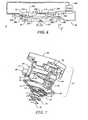
- Fig. 17is a bottom-up perspective view of an apparatus, shown in Fig. 5 , used to vary dimensions of a template;
- Fig. 18is top-down perspective view of the apparatus shown in 17;
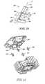
- Fig. 19is detailed side view of a lever sub-assembly, shown in Figs. 17 and 18 , in accordance with the present invention.
- Fig. 20is an exploded perspective view of the actuator sub-assembly, flexure device, shown in Fig. 5 , with pivots;
- Fig. 21is a detailed perspective view of one of the pivots shown in Fig. 20 ;
- Fig. 22is a top down view of a wafer, shown in Figs. 2, 3 and 4 , upon which imprinting layers are disposed;
- Fig. 23is a detailed view of Fig. 22 showing the position of the mold in one of the imprint regions;
- Fig. 24is a bottom-up plan view of the chuck body, shown in Fig. 16 , in accordance with an alternate embodiment
- Fig. 25is a cross-sectional view of a chuck body, shown in Fig. 16 ;
- Fig. 26is a flow diagram showing a method of reducing distortions in patterns formed using imprint lithography techniques in accordance with the present invention.
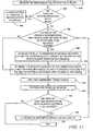
- Fig. 27is a flow diagram showing a method of reducing distortions in patterns formed using imprint lithography techniques in accordance with an alternate embodiment of the present invention.
- Fig. 1depicts a lithographic system 10 in accordance with one embodiment of the present invention that includes a pair of spaced-apart bridge supports 12 having a bridge 14 and a stage support 16 extending therebetween. Bridge 14 and stage support 16 are spaced-apart. Coupled to bridge 14 is an imprint head 18, which extends from bridge 14 toward stage support 16. Disposed upon stage support 16 to face imprint head 18 is a motion stage 20. Motion stage 20 is configured to move with respect to stage support 16 along X and Y axes, but may move along the Z-axis as well. An exemplary motion stage device is disclosed in United States published patent application number 2004-0008334, filed July 11, 2002 , entitled “Step and Repeat Imprint Lithography Systems," assigned to the assignee of the present invention. A source 22 is coupled to system 10 to impinge actinic energy upon motion stage 20. Operation of system 10 is under control of a processor 31 in data communication with a memory 33 containing computer readable code that defines instructions to regulate the operation of the various components of system 10.
- Mold 28includes a plurality of features defined by a plurality of spaced-apart recessions 27 and protrusions 29.
- the plurality of featuresdefines an original pattern that forms the basis of a pattern to be transferred into a wafer 30 positioned on motion stage 20.
- imprint head 18is adapted to move along the Z axis and vary a distance "d" between mold 28 and wafer 30, but may move along the X and Y axes as well. In this manner, the features on mold 28 may be imprinted into a flowable region of wafer 30, discussed more fully below.
- Source 22is located so that mold 28 is positioned between source 22 and wafer 30.
- mold 28is fabricated from material that allows it to be substantially transparent to the energy produced by source 22.
- a flowable regionis formed on a portion of surface 32 that presents a substantially planar profile.
- the flowable regionmay be formed using any known technique such as a hot embossing process disclosed in United States patent number 5,772,905 , or a laser assisted direct imprinting (LADI) process of the type described by Chou et al. in Ultrafast and Direct Imprint of Nanostructures in Silicon, Nature, Col. 417, pp. 835-837, June 2002 .
- LADIlaser assisted direct imprinting
- flowable regionconsists of a plurality of spaced-apart discrete droplets 36 of the imprinting material on wafer 30, discussed more fully below.
- Droplets 36include imprinting material that may be selectively polymerized and cross-linked to record a pattern corresponding to the original pattern therein, defining a recorded pattern formed into an imprint layer 34.
- An exemplary composition for the imprinting materialis disclosed in United States published patent application number 2004-0256764, filed June 16, 2003 and entitled "Method to Reduce Adhesion Between a Conformable Region and a Pattern of a Mold.”
- the pattern recorded in imprinting layer 34is produced, in part, by interaction with mold 28, e.g., mechanical contact, electrical contact and the like.
- the distance “d”is reduced to allow droplets 36 to come into mechanical contact with mold 28, and form a contiguous formation of the imprinting material over surface 32 that may subsequently be solidified to form imprinting layer 34.
- distance "d”is reduced to allow sub-portions 35 of imprinting layer 34 to ingress into and fill recessions 27.
- imprinting material employedpossesses the desired properties to completely fill recessions 27 while covering surface 32 with a contiguous formation of the imprinting material.
- sub-portions 37 of imprinting layer 34 in superimposition with protrusions 29remain after the desired, usually minimum distance "d", has been reached, leaving sub-portions 35 with a thickness t 1 , and sub-portions 37 with a thickness, t 2 .
- Thicknesses "t 1 " and "t 2 "may be any thickness desired, dependent upon the application.
- source 22produces actinic energy that polymerizes and cross-links the imprinting material, forming cross-linked polymer material.
- the composition of imprinting materialtransforms from a liquified state to a solidified state.
- the imprinting materialis solidified to provide imprinting layer 34 with a side having a shape conforming to a shape of a surface 39 of mold 28, shown more clearly in Fig. 3 .
- distance "d"is increased so that mold 28 and solidified imprinting layer 34 are spaced-apart.
- additional processingmay be employed to complete the patterning of wafer 30.
- wafer 30 and solidified imprinting layer 34may be etched to transfer a pattern of solidified imprinting layer 34 into wafer 30, providing a patterned surface 294, shown in Fig. 4 .
- the material from which solidified imprinting layer 34 is formedmay be varied to define a relative etch rate with respect to wafer 30, as desired.
- solidified imprinting layer 34may be provided with an etch differential with respect to photo-resist material (not shown) selectively disposed thereon.
- the photo-resist materialmay be provided to further pattern solidified imprinting layer 34, using known techniques. Any etch process may be employed, dependent upon the etch rate desired and the underlying constituents that form wafer 30 and solidified imprinting layer 34. Exemplary etch processes may include plasma etching, reactive ion etching, chemical wet etching and the like. It should be understood that wafer 30 is used in a general sense and may include any type of substrate suitable for patterning with the described process. For example, wafer 30 may be a bare semiconductor wafer 34 with or without a native oxide thereon, e.g., a silicon wafer. Alternatively, wafer 30 may have one or more layers disposed thereon, such as a primer layer formed from a material sold under a tradename DUV30J-6 available from Brewer Science, Inc. of Rolla, Missouri.
- a primer layerformed from a material sold under a tradename DUV30J-6 available from Brewer Science, Inc. of Rolla, Missouri.
- an exemplary source 22may produce ultraviolet energy.
- Other energy sourcesmay be employed, such as thermal, electromagnetic and the like.
- the selection of energy employed to initiate the polymerization of the imprinting materialis known to one skilled in the art and typically depends on the specific application which is desired.
- the plurality of features on mold 28are shown as recessions 27 extending along a direction parallel to protrusions 29 that provide a cross-section of mold 28 with a shape of a battlement.
- recessions 27 and protrusions 29may correspond to virtually any feature desired, including features to create an integrated circuit and may be as small as a few nanometers.
- bridge supports 12, bridge 14, and/or stage support 16may be fabricated from one or more of the following materials: iron alloys available under the trade name INVAR ® , or name SUPER INVAR TM , ceramics, including but not limited to ZERODUR ® ceramic and silicon carbide.
- a table 24may be constructed to isolate the remaining components of system 10 from vibrations in the surrounding environment.
- An exemplary table 24is available from Newport Corporation of Irvine, California.
- template 26, upon which mold 28 is present,is coupled to imprint head 18, shown in Fig. 1 , via chuck body 42.
- Body 42is coupled to a flexure 41.
- Flexure 41is coupled to an orientation system 43 that controls movement of template 26.
- orientation system 43is shown having an inner frame 44 disposed proximate to an outer frame 46, and flexure ring 48, discussed more fully below.
- Body 42is coupled to orientation system 43, shown more clearly in Fig. 8 through flexure 41.
- body 42is connected to flexure 41, using any suitable means, such as threaded fasteners (not shown) located at the four corners of body 42 connecting to four corners of flexure 41 closest to the four corners of body 42.
- Four corners 47 of flexure 41 that are closest to a surface 45 of inner frame 44are connected thereto using any suitable means, such as threaded fasteners, not shown.
- inner frame 44has a central throughway 50
- outer frame 46has a central opening 52 in superimposition with central throughway 50
- Flexure ring 48has an annular shape, e.g., circular or elliptical, and is coupled to inner frame 44 and outer frame 46 and lies outside of both central throughway 50 and central opening 52. Specifically, flexure ring 48 is coupled to inner frame 44 at regions 54, 56, and 58, outer frame 46 at regions 60, 62 and 64 using any suitable means, such as threaded fasteners (not shown).
- Region 60is disposed between regions 54 and 56 and disposed equidistant therefrom; region 62 is disposed between regions 56 and 58 and disposed equidistant therefrom; and region 64 is disposed between regions 54 and 58 and disposed equidistant therefrom.
- flexure ring 48surrounds flexure 41, body 42, and template 26 and fixedly attaches inner frame 44 to outer frame 46.
- orientation system 43 and flexure 41may be formed from any suitable material, e.g., aluminum, stainless steel and the like. Additionally, flexure 41 may be coupled to orientation system 43 using any suitable means. In the present example, flexure 41 is coupled to surface 45 employing threaded fasteners (not shown) located at the four corners of body 42.
- Orientation system 43is configured to control movement of template 26 and to place the same in a desired spatial relationship with respect to a reference surface (not shown).
- a plurality of actuators 66, 68 and 70are connected between outer frame 46 and inner frame 44 so as to be spaced about orientation system 43.
- Each of actuators 66, 68 and 70has a first end 72 and a second end 74.
- First end 72faces outer frame 46
- second end 74faces inner frame 44.
- Actuators 66, 68 and 70tilt inner frame 44 with respect to outer frame 46 by facilitating translational motion of inner frame 44 along three axes Z 1 , Z 2 , and Z 3 .
- Orientation system 43may provide a range of motion of approximately ⁇ 1.2 mm about axes Z 1 , Z 2 , and Z 3 .
- actuators 66, 68 and 70cause inner frame 44 to impart angular motion to both flexure 41 and, therefore, template 26 and body 42, about one or more of a plurality of axes T 1 , T 2 and T 3 .
- angular motion about tilt axis T 2occurs in a first direction.
- angular motion about tilt axis T 2occurs in a second direction opposite to the first direction.
- angular movement about axis T 1may occur by varying the distance between inner frame 44 and outer frame 46 by movement of inner frame 44 along axes Z 1 and Z 2 in the same direction and magnitude while moving of the inner frame 44 along axis Z 3 in a direction opposite and twice to the movement along axes Z 1 and Z 2 .
- angular movement about axis T 3may occur by varying the distance between inner frame 44 and outer frame 46 by movement of inner frame 44 along axes Z 1 and Z 3 in the same direction and magnitude while moving of inner frame 44 along axis Z 2 in direction opposite and twice to the movement along axes Z 1 and Z 3 .
- Actuators 66, 68 and 70may have a maximum operational force of ⁇ 200 N.
- Orientation System 43may provide a range of motion of approximately ⁇ 0.15° about axes T 1 , T 2 , and T 3 .
- Actuators 66, 68 and 70are selected to minimize mechanical parts and, therefore, minimize uneven mechanical compliance, as well as friction, which may cause particulates.
- Examples of actuators 66, 68 and 70include voice coil actuators, piezo actuators, and linear actuators.
- An exemplary embodiment for actuators 66, 68 and 70is available from BEI Technologies of Sylmar, California under the trade name LA24-20-000A and are coupled to inner frame 44 using any suitable means, e.g., threaded fasteners.
- actuators 66, 68 and 70are coupled between inner frame 44 and outer frame 46 so as to be symmetrically disposed thereabout and lie outside of central throughway 50 and central opening 52. With this configuration an unobstructed throughway between outer frame 46 to flexure 41 is configured. Additionally, the symmetrical arrangement minimizes dynamic vibration and uneven thermal drift, thereby providing fine-motion correction of inner frame 44.
- the combination of the inner frame 44, outer frame 46, flexure ring 48 and actuators 66, 68 and 70provides angular motion of flexure 41 and, therefore, body 42 and template 26 about tilt axes T 1 , T 2 and T 3 . It is desired, however, that translational motion be imparted to template 26 along axes that lie in a plane extending transversely, if not orthogonally, to axes Z 1 , Z 2 , and Z 3 .
- flexure 41with the functionality to impart angular motion upon template 26 about one or more of a plurality of compliance axes, shown as C1 and C2, which are spaced-part from tilt axes T 1 , T 2 and T 3 and exist on the surface of the template when the template, the template chuck, and the compliant device are assembled.
- flexure 41includes a support body 76 and a floating body 78 that is coupled to the support body 76 vis-à-vis a plurality of flexure arms 80, 82, 84 and 86.
- Body 42is intended to be mounted to floating body 78, as discussed above, and template 26 is retained by chucking system 40 using conventional methods, discussed more fully below, shown in Fig. 6 .
- each of flexure arms 80, 82, 84 and 86includes first and second sets of flexure joints 88, 90, 92 and 94.
- the first and second sets of flexure joints 88, 90, 92 and 94are discussed with respect to flexure arm 88 for ease of discussion, but this discussion applies equally to the sets of flexure joints associated with flexure arms 80, 84 and 86.
- flexure 41is formed from a solid body.
- support body 76, floating body 78 and flexures arms 80, 82, 84 and 86are integrally formed, and are rotationally coupled together vis-à-vis first and second sets of flexure joints 88, 90, 92 and 94.
- Support body 76includes a centrally disposed throughway 96.
- Floating body 78includes a centrally disposed aperture 98 that is in superimposition with throughway 96.
- Each flexure arm 80, 82, 84 and 86includes opposed ends, 99 and 100. End 99 of each flexure arm 80, 82, 84 and 86 is connected to support body 76 through flexure joints 92 and 94. End 99 lies outside of throughway 96. End 100 of each flexure arm 80, 82, 84 and 86 is connected to floating body 78 through flexure joints 88 and 90. End 100 lies outside of aperture 98.
- each of joints 88, 90, 92 and 94are formed by reducing material from flexure 41 proximate to ends 99 and 100, i.e., at an interface either of support body 76 or floating body 78 and one of flexure arms 80, 82, 84 and 86.
- flexure joints 88, 90, 92 and 94are formed by machining, laser cutting or other suitable processing of flexure 41.
- joints 90 and 92are formed from a flexure member 102 having two opposing surfaces 104 and 106 and two hiatuses 108 and 110.
- Hiatus 108is positioned facing away from hiatus 110, and hiatus 110 faces away from hiatus 108.
- Extending from hiatus 110, away from surface 104is a gap 112, terminating in an opening in a periphery of flexure arm 82.
- Joint 94is also formed from a flexure member 114 having two opposing surfaces 116 and 118 and two hiatuses 120 and 122.
- Hiatus 122is disposed opposite to surface 118.
- Extending from hiatus 122, away from surface 116is a gap 123, and extending from hiatus 120 is a gap 125.
- the spacing S 1 , S 2 and S 3 of gaps 112, 123, and 125respectively define a range of motion over which relative movement between either of support body 76 and floating body 78 may occur.
- flexure member 114 associated with joints 88 of flexure arms 82 and 84facilitates rotation about axis 124, and flexure member 102 associated with joints 92 of flexure arms 82 and 84 facilitates rotation about axis 126.
- Flexure member 114 associated with joints 88 of flexure arms 80 and 86facilitates rotation about axis 128, and flexure member 102 associated with joints 92 of flexure arms 80 and 86 facilitates rotation about axis 130.
- Flexure member 102 associated with joints 90 of flexure arms 80 and 82facilitates rotation about axis 132, and flexure member 114 associated with joints 94 of flexure arms 80 and 82 facilitates rotation about axis 134.
- Flexure member 102 associated with joints 90 of flexure arms 84 and 86facilitates rotation about axis 136, and flexure member 114 associated with joints 94 of flexure arms 84 and 86 facilitates rotation about axis 138.
- each flexure arm 80, 82, 84 and 86is located at a region of flexure 41 where groups of the axes of rotation overlap.
- end 99 of flexure arm 80is located where axes 130 and 134 overlap and end 100 is positioned where axes 128 and 132 overlap.
- End 99 of flexure arm 82is located where axes 126 and 134 overlap, and end 100 is positioned where axes 124 and 132 overlap.
- End 99 of flexure arm 84is located where axes 138 and 126 overlap, and end 100 is located where axes 124 and 136 overlap.
- end 98 of flexure arm 86is located where axes 130 and 138 overlap, and end 100 is located where axes 136 and 128 overlap.
- each flexure arm 80, 82, 84 and 86is coupled to provide relative rotational movement with respect to support body 76 and floating body 78 about two groups of overlapping axes with a first group extending transversely to the remaining group.
- Thisprovides each of flexure arms 80, 82, 84 and 86 with movement about two groups of orthogonal axes while minimizing the footprint of the same.
- Flexure 41may provide a tilting motion range of approximately ⁇ 0.04°, an active tilting motion range of approximately ⁇ 0.02°, and an active theta motion range of approximately ⁇ 0.0005° above the above mentioned axes.
- each flexure arm 80, 82, 84 and 86allows leaving a void between throughway 96 and aperture 98 unobstructed by flexure arms 80, 82, 84 and 86. This makes flexure 41 suited for use with an imprint lithography system.
- each flexures arms 80, 82, 84 and 86imparts an substantially equal amount of force F1 upon floating body 78.
- thisfacilitates obtaining a desired structural stiffness with flexure 41 when loaded with either a force F 1 or a force F 2 .
- joints 88, 90, 92 and 94are revolute joints which minimize movement, in all directions, between the flexure and either support body 76 or floating body 78 excepting rotational movement. Specifically, joints 88, 90, 92 and 94 minimize translational movement between flexure arms 80, 82, 84 and 86, support body 76 and floating body 78, while facilitating rotational movement about axes 124, 126, 128, 130, 132, 134, 136 and 138.
- the relative position of axes 124, 126, 128 and 130provides floating body 78 with a first remote center of compliance (RCC) at a position 140 spaced apart from floating body 78, centered with respect to aperture 98 and axes 124, 126, 128 and 130.
- RCCremote center of compliance
- the relative position of axes 122, 124, 136 and 138provides floating body 78 with a second RCC substantially close to position 140 and desirably located at position 140, which is substantially centered with respect to axes 132, 134, 136 and 138 is positioned equidistant from position 140.
- Each axis of the group of axes 124, 126, 128 and 130extends parallel to the remaining axes 124, 126, 128 and 130 of the group.
- each axis of the group of axes 132, 134, 136 and 138extends parallel to the remaining axes 132, 134, 136 and 138 of the group and orthogonally to each axis 124, 126, 128 and 130.
- Axis 130is spaced-apart from axis 128 along a first direction a distance d 1 and along a second orthogonal direction a distance d 2 .
- Axis 124is spaced-apart from axis 126 along the second direction a distance d 3 and along the first direction a distance d 4 .
- Axis 132is spaced-apart from axis 134 along a third direction, that is orthogonal to both the first and second directions a distance d 5 and along the first direction a distance d 6 .
- Axis 136is spaced-apart from axis 138 along the first direction a distance d 7 and along the third direction a distance d 8 .
- Distances d 1 , d 4 , d 6 and d 7are substantially equal.
- Distances d 2 , d 3 , d 5 and d 8are substantially equal.
- two sets of transversely extending axesmay be in substantially close proximity such that RCC may be considered to lie upon an intersection thereat by appropriately establishing distances d 1 -d 8 .
- a first set ofincludes four axes is shown as 144, 146, 148 and 150.
- Joints 88 and 92 of flexure arm 80lie along axis 144, and joints 88 and 92 of flexure arm 82 lie along axis 146.
- Joints 88 and 92 of flexure arm 84lie along axis 148, and joints 88 and 92 of flexure arm 86 lie along axis 150.
- a second set of four axesis shown as 152, 154, 156, and 158.
- Joints 90 and 94 of flexure arm 82lie along axis 152, and joints 90 and 94 of flexure arm 84 lie along axis 154.
- Joints 90 and 94 of flexure arm 86lie along axis 156, and joints 90 and 94 of flexure arm 80 lie along axis 158.
- chuck body 42is adapted to retain template 26, upon which mold 28 is attached, employing vacuum techniques.
- chuck body 42includes first 160 and second 162 opposed sides.
- a side, or edge, surface 164extends between first side 160 and second side 162.
- First side 160includes a first recess 166 and a second recess 168, spaced-apart from first recess 166, defining first 170 and second 172 spaced-apart support regions.
- First support region 170cinctures second support region 172 and the first 166 and second 168 recesses.
- Second support region 172cinctures second recess 168.
- a portion 174 of chuck body 42 in superimposition with second recess 168is transparent to energy having a predetermined wavelength, such as the wavelength of the actinic energy mentioned above.
- portion 174is made from a thin layer of transparent material, such as glass.
- the material from which portion 174 is mademay depend upon the wavelength of energy produced by source 22, shown in Fig. 2 .
- portion 174extends from second side 162 and terminates proximate to second recess 168 and should define an area at least as large as an area of mold 28 so that mold 28 is in superimposition therewith.
- Formed in chuck body 42are one or more throughways, shown as 176 and 178.
- One of the throughways, such as throughway 176places first recess 166 in fluid communication with side surface 164.
- the remaining throughway, such as throughway 178places second recess 168 in fluid communication with side surface 164.
- throughway 176may extend between second side 162 and first recess 166, as well.
- throughway 178may extend between second side 162 and second recess 168. What is desired is that throughways 176 and 178 facilitate placing recesses 166 and 168, respectively, in fluid communication with a pressure control system, such a pump system 180.
- Pump system 180may include one or more pumps to control the pressure proximate to recesses 166 and 168, independently of one another. Specifically, when mounted to chuck body 42, template 26 rests against first 170 and second 172 support regions, covering first 166 and second 168 recesses. First recess 166 and a portion 182 of template 26 in superimposition therewith define a first chamber 184. Second recess 168 and a portion 186 of template 26 in superimposition therewith define a second chamber 188. Pump system 180 operates to control a pressure in first 184 and second 188 chambers.
- the pressureis established in first chamber 184 to maintain the position of the template 26 with the chuck body 42 and reduce, if not avoid, separation of template 26 from chuck body 42 under force of gravity g.
- the pressure in the second chamber 188may differ from the pressure in the first chamber 184 to, inter alia, reduce distortions in the template 26 that occur during imprinting, by modulating a shape of template 26.
- pump system 180may apply a positive pressure in chamber 188 to compensate for any upward force R that occurs as a result of imprinting layer 34, shown in Fig. 2 , contacting mold 28. In this manner, produced is a pressure differential between differing regions of side 160 so that bowing of template 26 and, therefore, mold 28 under force R is attenuated, if not avoided.
- Coupled to template 26is a means for varying dimensions of the same in X and Y directions, with the understanding that the Y-direction is into the plane of Fig. 6 .
- the means for varying dimensionsis shown schematically as an actuator sub-assembly 190, which is coupled to chuck body 42, shown in exploded view in Fig. 5 .
- Pump system 180 and actuator sub-assembly 190are operated under control of processor 31, shown in Fig. 1 .
- actuator sub-assembly 190is configured to subject template 26 to purely compressive forces so that out-of-plane bending forces are substantially minimized, if not avoided entirely. Forces causing bending of template 26 are problematic in that the same results in pattern distortion.
- actuator sub-assembly 190includes a plurality of lever sub-assemblies mounted to a frame 192 having a central aperture 194 to direct compressive forces along a neutral axis of template 26.
- Each of lever sub-assemblies 196includes a body 198 coupled to a lever arm 200, an actuation system 202 and a linkage system 204.
- Lever arm 200is coupled to body 198 through linkage system 204.
- lever arm 200, body 198 and linkage system 204are integrally formed from a solid material, e.g., aluminum, stainless steel and the like.
- a piston 206 of actuation system 202is coupled to a terminus region 208 of lever arm 200 through a flex joint 212 and may push or pull against terminus region 208.
- a second terminus region 210 of lever arm 200is coupled to linkage system 204 to impart a force thereon.
- lever sub-assemblies 196is mounted to frame 192 so that linkage system 204 is positioned on a first side 214 of frame 192.
- Frame 192as are most if not all of the metallic components of sub-assembly 190, is formed from aluminum, stainless steel or the like.
- Actuation system 202is positioned on a second side 215 of frame 192, disposed opposite to first side 214, with lever arm 200 extending therebetween.
- actuation system 202may be any force or displacement actuator known in the art, such as pneumatic, piezoelectric, magnetostrictive, voice coils, in the present example actuation system is an actuator available from SMC Corporation of America located in Indianapolis, Indiana under the product number11-CUJB10-4D.
- Each body 198 of lever sub-assemblies 196extends from linkage system 204 away from lever arm 200 toward aperture 194 and terminates in superimposition therewith.
- sub-assembliesmay be coupled to differing frames, but it is desirable that opposed sub-assemblies be coupled to a common frame.
- aperture 194may have any shape desired, typically aperture 194 has a shape complementary to the shape of template 26. To that end, and as shown, aperture 194 is square. Further, it is desired that each of the plurality of bodies 198 be disposed opposite one of the remaining bodies 198 of the plurality of bodies 198. To that end, there are an equal number of bodies 198 on opposing sides of aperture 194. Although four lever sub-assemblies 196 are shown, providing four bodies 198 to a side of aperture 194, any number may be present. More specifically, each lever sub-assembly 196 may be made smaller such that a greater number of lever sub-assemblies 196 may be employed to provide a finer precision of the distortion control of template 26.
- an areais defined between the plurality of bodies 198 in which template 26 may be centered.
- An advantage with the present designis that the entire actuator sub-assembly 190 is positioned to lie on one side of mold 28 so as to be spaced-apart from a plane in which mold surface 39, shown in Fig. 3 , lies. This is beneficial in preventing contact between the components of actuator sub-assembly 190, shown in Fig. 5 , and a wafer 30, shown in Fig. 3 , during imprint processes.
- actuator sub-assembly 190applies a force to terminus region 208 to provide aperture 194 with appropriate dimensions to receive template 26.
- aperture 194may have dimensions that are smaller than the dimensions of template 26.
- actuator sub-assembly 190may operate to pull against terminus region 208 and cause retraction of body 198 away from an opposing body 198 to increase the size of aperture 194 for loading of template 26.
- Template 26is disposed within aperture 194 and held in place via chucking system 40, shown in Fig. 6 . Referring again to Figs.
- body 198is allowed to press against template 26 without force being generated by actuation system 202.
- the size of aperture 194may be greater than the dimension of template 26, requiring a force to be generated by actuation system 202 to achieve contact between template 26 and body 198.
- Bodies 198are arranged so that a contact surface 220 is included in body 198 to contact a side 218 of template 26. Specifically, a contact surface 220 is configured to extend parallel to side 218 and make contact therewith.
- actuation system 202is coupled to pump system 180, shown in Fig. 6 , to cause actuation system 202 to impart angular movement of lever arm 200.
- Piston 206imparts a force F IN upon one end of lever arm 200 through flexure joint 212. This causes lever arm 200 to undergo rotational movement that causes body 198 to undergo translational movement toward template 26, thereby decreasing the area defined by the plurality of bodies 198. In this manner, a force F OUT is imparted upon side 218 of template 26.
- dimensional variations of template 26may be achieved.
- the dimensional variations of template 26are imparted upon mold 28, which may be employed to compensate for magnification errors, discussed more fully below.
- linkage 204is designed to control the direction of travel of body 198 and lever arm 200. Additionally the structural connection of sub-assemblies 196 to common frame 192 ensures that high forces are reacted in frame 192, as opposed to other components, such as chuck body 42 and, therefore, template 26.
- Linkage 204includes a linkage member 224 and a plurality of flexure joints, shown as 226, 228, 230, 232, 234 and 236.
- Each of flexure joints 226, 228, 230, 232, 234 and 236are regions of material of linkage member 224 has substantially reduced material.
- Flexure joint 226defines a pivot axis 238 about which lever arm 200 undergoes rotational/angular movement in response to force F IN imparted upon lever arm 200 by piston 206 of actuation system 202 at terminus region 208.
- the rotational/angular movement of lever arm 200 about pivot axis 238causes body 198 to move in a direction 240 that is transverse, if not orthogonal, to pivot axis 238.
- direction 240is precisely controlled so that deviation therefrom is minimized. This reduces, if not avoids, out-of-plane bending of template 26 upon being subjected to force F OUT by the plurality of bodies 198. Force F OUT is directed along terminus region 210 of lever arm 200 onto linkage system 204.
- Flexure joints 228, 230, and 232 in addition to flexure joint 226facilitate rotational/angular movement between lever arm 200 and body 198 while ensuring that deviation of body 198 from direction 240 is minimized.
- each of flexure joints 228, 230, and 232defines an axis of rotation, 242, 244, and 246, respectively, about which rotational/angular movement between lever arm 200 and body 198 may occur.
- Axes 238, 242, 244, and 246extend parallel, with axes 238 and 242 being substantially in superimposition with one another and axes 244 and 246 being substantially in superimposition with one another.
- Axes 238 and 244lie in a common plane and axes 242 and 246 lie in a common plane.
- lever arm 200 and linkage 204may function as an amplifier.
- the force F OUT applied to linkage system 204is a function of force F IN and the position of axis 238 between terminus regions 208 and 210.
- linkage system 204includes joints 234 and 236. Joints 234 and 236 facilitate rotational/angular movement of body 198 with respect to lever member 224 along two transversely extending axes 248 and 250. By providing body 198 with rotational freedom about axes 248 and 250, body 198 may change position to compensate for obliqueness of side 218 with respect to contact surface 220. In this manner, contact surface 220 will maintain contact with side 218 so as to reduce, if not prevent, localized stresses resulting from, inter alia, having a corner of contact surface 220 contacting side 218.
- contact surface 220may be formed from a compliant material, so that localized stresses on side 218 resulting from non-conformity of contact surface 220 with side 218 is minimized.
- exemplary materials from which contact surface may be formedinclude TEFLON ® , fluorosilicone, urethane and Delrin/AF. Further compliance with surface anomalies of side 218 may be achieved by allowing independent control over body 198, one among the plurality of bodies 198, and, therefore, contact surface 220.
- Actuator sub-assembly 190facilitates varying dimensions of template 26 in two dimensions. This is particularly useful in overcoming Poisson's effect. Poisson's effect may result in linear coupling of strain in orthogonal directions of template 26. Specifically, the Poisson ratio is the ratio between the tensile strain caused in the Y and Z directions in template 26 to the compressive strain imparted to template 26 in the X direction. Typical numbers are in the range of 0.1-0.4. Were template 26 formed from fused silica, the ratio is approximately 0.16.
- actuator sub-assembly 190may necessitate activation of actuator sub-assembly 190 to vary both distances d 1 and d 2 , to compensate for Poisson's effect.
- a forcemay be applied to template 26 to vary the dimensions of the same and reduce distortions in the pattern recorded into imprinting layer 34, shown in Fig. 2 .
- varying template dimensionsanother important consideration when varying template dimensions is to minimize the deleterious effects of the forces employed. For example, when varying template dimensions, forces on the order of hundreds of pounds may be exerted. It is desirable to minimize the amount of these forces felt on other units of system 10, such as orientation system 43. In addition, it is desirable that template 26 neither rotate with respect to chuck body 42 about the Z-axis nor become displaced along the X and Y directions with respect to body 42, such as in the presence of unequal compression forces exerted upon side 218 by bodies 198.
- actuator sub-assembly 190is pivotally/elastically coupled to flexure 41 to move in a plane along X and Y directions and rotate about the Z direction in response to reaction forces generated when actuator sub-assembly compresses template 26.
- the force by which template is held against chuck body 42minimizes, if not prohibits, bulk and rotational movement of template 26 with respect to chuck body 42 in the presence of compression forces.
- Thisis accomplished by coupling each corner 252, 254, 256 and 258, of actuator sub-assembly 190 to a corner 260, 262, 264 and 266, of flexure 41 through a pliant member 268 using any suitable fastening means, such as threaded fasteners (not shown).
- each pliant member 268includes opposed termini 270 and 272 with a dual fulcrum lever system 274 extending from terminus 270 toward terminus 272, terminating in a fulcrum 276.
- Fulcrum 276is located between opposed termini 270 and 272.
- Fulcrum lever system 274includes a lever 278, extending from fulcrum 276, along direction Z toward terminus 270, terminating in a base 280.
- Base 280is coupled to lever 278 defining a fulcrum 282 thereat.
- Base 280extends from fulcrum 282, transversely to direction Z. Extending from fulcrum 276 is a support 284 that terminates in a base 285.
- Support 284extends from fulcrum 276 toward terminus 270 and is disposed opposite to, and spaced apart from, lever 278.
- Base 285extends from support 284 away from lever 278 and is positioned in superimposition with, and spaced apart from, base 280.
- Base 280is fixedly attached to actuator sub-assembly 190, and base 285 is fixedly attached to flexure 41. To that end, a plurality of threaded fasteners (not shown) is coupled to each of base 285 and base 280. With this configuration, relative movement between actuator sub-assembly 190 and flexure 41 is facilitated. Having one pliant member 268 coupling together each pair of corners, i.e., one of the corners of flexure 41 with one of the corners of actuator sub-assembly 190, allows each lever 278 to function as a parallel four-bar linkage in space.
- fulcrum 276facilitates relative movement about axis 288, and fulcrum 282 facilitates relative movement about axis 290.
- relative rotational movement about axis Zis facilitated by lever 278.
- the rigidity of lever 278minimizes, if not prevents, translational movement along the Z direction.
- actuator sub-assembly 190is allowed to accommodate loading tolerances and unequal forces between template 26 and actuator sub-assembly 190. For example, were template 26 loaded on body 42 with theta error, e.g., not properly aligned rotationally about the Z direction with respect to chuck body 42, then the actuator sub-assembly 190 may rotate about the Z direction to accommodate for the misalignment. In addition, were the sum of the forces applied to template 26 by opposing bodies 198 not to cancel, the actuator sub-assembly 190 accommodates for non-equilibrium of the forces applied by moving in the x and/or Y directions and/or rotating about the Z direction. For example, it is desired that each of the plurality of lever sub-assemblies 196 operate independently of the remaining lever sub-assemblies 196. A large number of combinations of forces can be applied to template 26 to correct for magnification and distortion errors.
- the area of template 26may be increased such that a greater number of lever sub-assemblies 196 may be employed to apply compressive forces to template 26.
- the larger number of lever sub-assemblies 196allow a finer precision of the distortion control of template 26.
- a subset of, or each of, lever sub-assemblies 196may be constructed to have bodies 198 of smaller dimensions to increase the number thereof coupled to side 218. In this manner, improved distortion correction may be achieved due to the increased resolution of correction afforded by increasing a number of bodies 198 on side 218.
- the area of side 218may be increased, requiring appropriate scaling of actuator sub-assemblies 190 to accommodate template 26 of increased size.
- Another advantage of increasing the size of template 26is that the area of template 26 outside of mold 28 filters, e.g., attenuates, deleterious effects of stress concentrations of bodies 198 on side 218. The stress concentration creates strain variations at mold 28, which results in pattern distortions in the pattern on mold 28.
- the number of bodies 198 per unit area of side 218is proportional to the resolution of distortion correction.
- decreasing the area of mold 28 with respect to the remaining regions of template 26reduces the pattern distortions caused by bodies 198 contacting side 218.
- distortions in the pattern recorded into imprinting layer 34may arise from, inter alia, dimensional variations of imprinting layer 34 and wafer 30. These dimensional variations, which may be due in part to thermal fluctuations, as well as, inaccuracies in previous processing steps that produce what is commonly referred to as magnification/run-out errors.
- the magnification/run-out errorsoccur when a region of wafer 30 in which the original pattern is to be recorded exceeds the area of the original pattern. Additionally, magnification/run-out errors may occur when the region of wafer 30, in which a pattern is to be recorded, has an area smaller than the original pattern.
- a step-and-repeat processincludes defining a plurality of regions, shown as, a-1, on wafer 30 in which a pattern corresponding to the original on mold 28 will be recorded.
- the original pattern on mold 28may be coextensive with the entire surface of mold 28, or simply located on a sub-portion thereof.
- the present inventionwill be discussed with respect to the original pattern being coextensive with the surface of mold 28 that faces wafer 30.
- Step-and-repeat imprint lithography processesmay be achieved in a variety of manners. For example, the entire surface of wafer 30 may be coated with droplets 36, shown in Fig.
- each region a-1would include the requisite volume of imprinting material so that the same would not egress into adjacent regions a-1 upon being patterned by mold 28 and subsequently solidified, as discussed above.
- all the imprinting material required to pattern regions a-1is deposited over the surface of wafer before solidification and imprinting material in any of regions a-1.
- a sub-portion of regions a-1e.g., one of regions a-1, may be provided with imprinting material that is subsequently patterned and solidified before remaining regions of a-1 are provided with any imprinting material.
- the entire surface of wafermay be provided with imprinting material deposited employing spin-coating techniques followed by sequentially patterning and solidifying imprinting material in each of regions a-1.
- Proper execution of a step-and-repeat processmay include proper alignment of mold 28 with each of regions a-1.
- mold 28includes alignment marks 298, shown as a "+" sign.
- One or more of regions a-lincludes fiducial marks 296.
- machine vision devices(not shown) may be employed to sense the relative alignment between alignment marks 298 and fiducial marks 296. In the present example, proper alignment is indicated upon alignment marks 298 being in superimposition with fiducial marks 296. With the introduction of magnification/run-out errors, proper alignment becomes very difficult.
- magnification/run-out errorsare reduced, if not avoided, by creating relative dimensional variations between mold 28 and wafer 30.
- the relative dimensions of mold 28 and wafer 30are established so that at least one of regions a-l defines an area that is slightly less than an area of the original pattern on mold 28.
- the final compensation for magnification/run-out errorsis achieved by subjecting template 26, shown in Fig. 17 , to mechanical compression forces using actuator sub-assembly 190, which are in turn transferred to mold 28 shown by arrows F 1 and F 2 , F 3 , F 4 -F 8 , shown in Fig. 23 .
- the area of the original patternis made coextensive with the area of the region a-1 in superimposition therewith.
- patterns defined by mold 28may be generated to be slightly larger than nominal, e.g., slightly larger than desired. In this manner, it could be said that the original pattern defined by mold 28 has a fixed magnification associated therewith, compared to the nominal dimensions of the pattern desired to be recorded in one of regions a-1.
- Actuator sub-assembly 190is then employed to compress template 26 to provide the original pattern with a zero magnification. It is possible, however, to create thermal changes to vary the dimension of wafer 30 so that one of regions a-1 has dimensions that are slightly less than the dimensions of mold 28.
- support regions 170 and 172have surface regions 300 and 302, respectively, formed thereon from a combination of materials adapted to conform to a profile of said template 26 and resistant to bulk motion of template 26 along the X and Y axes, e.g., Buna-N, Viton, Silicone, TEFLON ® , FEP, Fluorosilicone, Urethane, Kalrez, Simriz, Buna-n, mirror polished anodized Al, Ni plating, or SiC surface, or polished TEFLON ® coating, a regular O-ring, TEFLON ® tube, TEFLON ® coating or any durable material that can be used to seal a vacuum in cleanroom environment.
- surface regions 300 and 302resist relative movement of template 26 with respect to chuck
- a chuck body 304 with walls/baffles 306, 308, 310 and 312facilitates providing sub-regions 314, 316, 318 and 320 with differing pressure levels, concurrently.
- the amount of force exerted on template 26 when being pulled-apart from imprinting layer 34may vary across the surface of template 26. This allows cantilevering, or peeling-off of template 26 from imprinting layer 34 that reduces distortions or defects from being formed in imprinting layer 34 during separation of mold 28 therefrom.
- sub-region 316may have a pressure established therein that is greater than the pressure associated with the remaining sub- regions 314, 318 and 320.
- chuck body 322may include a plurality of pins 324 projecting from a nadir surface 326 of out recess 328.
- Pins 324provide mechanical support for the template (not shown) retained on chuck body 322 via vacuum and resting against surfaces 330 and 332 of support regions 334 and 336, respectively.
- Surface regions 330 and 332provide a fluid-tight seal with the template (not shown).
- surfaces 330 and 332are polished to be optically flat and pins 324 extend from recess 328 terminating in a common plane with surface regions 330 and 332.
- pins 324Mechanical support of the template (not shown) in the Z direction is provided by support regions 334 and 336 and pins 324, with pins 324 typically being rigid posts having a circular or square cross-section. Pins 324 are arranged in a patter so that the mold (not shown) on template (not shown) is substantially flat when a nominal vacuum pressure is applied.
- an accurate measurement of wafer 30 in an X-Y planeis undertaken at step 400. This may be achieved by sensing gross alignment fiducials 338 present on wafer 30 using machine vision devices (not shown) and known signal processing techniques.
- the area of one of regions a-1is established to be slightly less than an area of the original pattern on mold 28.
- mold 28may be achieved by fabricating mold 28 to have a pattern thereon that is slightly larger than the area of one of regions a-1, and/or expanding mold 28 by varying the temperature thereof as for example, having mold 28 and wafer 30 in a temperature controlled environment (not shown) and varying the temperature of said environment causing dimensional changes that occur due to, inter alia, the differences in coefficients of thermal expansion of the materials from which mold 28 and wafer 30 are fabricated.
- the temperature of wafer 30may be varied, i.e., raised or lowered, so that the area of one of regions a-l is slightly less than an area of the original pattern on mold 28.
- the temperature variationsmay be achieved using a temperature controlled chuck or pedestal (not shown) against which wafer 30 rests.
- a change in the distance between two gross alignment fiducials 338 collinear along one of the X or Y axesis determined. Thereafter, this change in distance is divided by a number of adjacent regions a-1 on the wafer 30 along the X-axis. This provides the dimensional change of the areas of regions a-1 attributable to dimensional changes in wafer 30 along the X-axis. If necessary the same measurement may be made to determine the change in area of regions a-1 due to dimensional changes of wafer 30 along the Y-axis. However, it may also be assumed that the dimensional changes in wafer 30 may be uniform in the two orthogonal axles, X and Y.
- compressive forces, F 1-8are applied to mold 28 to establish the area of the original pattern to be coextensive with the area of one of the regions a-1 in superimposition with the pattern and proper alignment between the pattern on mold 28 and one of the regions a-1. This may be achieved in real-time employing machine vision devices (not shown) and known signal processing techniques, to determine when two or more of alignment marks 298 are aligned with two or more of fiducial marks 296.
- step 406after proper alignment is achieved and magnification/run-out errors are reduced, if not vitiated, the original pattern is recorded in the region a-1 that is in superimposition with mold 28, forming the recorded pattern.
- each lever sub-assembly 196 of actuator sub-assembly 190may operate independently. This affords application of differing force combinations F 1-8 to mold 28 to compensate for magnification distortion, as well as distortions that may be present in the pattern on mold, e.g., orthogonality distortions, such as skew distortions and keystone distortions.
- the dimensional variation in mold 28may be undertaken after mold 28 contacts an imprinting layer (not shown) in Fig. 4 . However, this is not necessary.
- the alignment of mold 28 with regions a-1 in superimposition therewithmay occur with mold 28 being spaced-apart from an imprinting layer (not shown).
- the magnification/run-out errorswere constant over the entire wafer 30, then the magnitude of forces F 1-8 could be maintained for each region a-1 in which the original pattern is recorded.
- steps 402 and 404, shown in Fig. 26would then be undertaken for each region a-1 in which the original pattern is recorded.
- the area of the regions a-1should be of appropriate dimensions to enable pattern on mold 28 to define an area coextensive therewith when mold 28 is subject to compression forces F 1-8 , without compromising the structural integrity of mold 28.
- step 500accurate measurement of wafer 30 in an X-Y plane is undertaken at step 500.
- step 502it is determined whether the original pattern on mold 28 has any distortions, e.g., skew distortions, keystone distortions and the like. If there are original pattern distortions, a force differential is established to create the requisite differences in magnitude among forces F 1-9 to remove the original pattern distortions, defining a force differential, at step 504. In this manner, skew distortions, keystone distortions and the like may be attenuated if not abrogated entirely to provide mold 28 with the original pattern desired.
- distortionse.g., skew distortions, keystone distortions and the like.
- step 506it is determined whether the area of one of regions a-1 in superimposition with mold 28 is larger than the area of the pattern on mold 28, at step 506. If this is the case, the process proceeds to step 508, otherwise the process proceeds to step 510.
- step 510mold 28 is placed in contact with the region a-1 in superimposition therewith, and the requisite magnitude of compressive forces F 1-8 is determined to apply to mold 28 to ensure that the area of pattern is coextensive with the area of this region a-1, with the compressive forces including the force differential.
- compressive forces F 1-8are applied to mold 28 and the pattern is recorded in wafer 30.
- step 514the pattern is recorded on wafer 30.
- step 516it is determined whether there remain any regions a-1 on wafer 30 in which to record a pattern. If there are, the process proceeds to step 518 wherein mold 28 is placed in superimposition with the next region and the process proceeds to step 506. Otherwise, the process ends at step 520.
- step 506Were it determined at step 506 that the region a-1 in superimposition with mold 28 had an area greater than the area of the pattern, then the process proceeds to step 508 wherein the temperature of mold 28 and/or wafer 30 is varied to cause expansion of the same.
- mold 28is heated at step 508 so that the pattern is slightly larger than the area of region a-1 in superimposition therewith. Then the process continues at step 512.
Landscapes
- Engineering & Computer Science (AREA)
- Physics & Mathematics (AREA)
- Nanotechnology (AREA)
- Chemical & Material Sciences (AREA)
- General Physics & Mathematics (AREA)
- Crystallography & Structural Chemistry (AREA)
- Condensed Matter Physics & Semiconductors (AREA)
- Theoretical Computer Science (AREA)
- Mathematical Physics (AREA)
- Manufacturing & Machinery (AREA)
- Shaping Of Tube Ends By Bending Or Straightening (AREA)
- Exposure Of Semiconductors, Excluding Electron Or Ion Beam Exposure (AREA)
- Micromachines (AREA)
- Casting Or Compression Moulding Of Plastics Or The Like (AREA)
- Optical Head (AREA)
- Manipulator (AREA)
- Bending Of Plates, Rods, And Pipes (AREA)
- Moulds For Moulding Plastics Or The Like (AREA)
- Electrodes Of Semiconductors (AREA)
Abstract
Description
- The government of these United States has a paid-up license in this invention and the right in limited circumstance to require the patent owner to license other on reasonable terms as provided by the terms of N66001-01-1-8964 and N66001-02-C-8011 awarded by the Defense Advanced Research Projects Agency (DARPA).
- The field of invention relates generally to imprint lithography. More particularly, the present invention is directed to reducing pattern distortions during imprint lithography processes.
- Micro-fabrication involves the fabrication of very small structures, e.g., having features on the order of micro-meters or smaller. One area in which micro-fabrication has had a sizeable impact is in the processing of integrated circuits. As the semiconductor processing industry continues to strive for larger production yields while increasing the circuits per unit area formed on a substrate, micro-fabrication becomes increasingly important. Micro-fabrication provides greater process control while allowing increased reduction of the minimum feature dimension of the structures formed. Other areas of development in which micro-fabrication has been employed include biotechnology, optical technology, mechanical systems and the like.
- An exemplary micro-fabrication technique is commonly referred to as imprint lithography and is described in detail in numerous publications, such as United States published patent applications
2004/0065976 , entitled METHOD AND A MOLD TO ARRANGE FEATURES ON A SUBSTRATE TO REPLICATE FEATURES HAVING MINIMAL DIMENSIONAL VARIABILITY;2004/0065252 , entitled METHOD OF FORMING A LAYER ON A SUBSTRATE TO FACILITATE FABRICATION OF METROLOGY STANDARDS; and2004/0046271 , entitled METHOD AND A MOLD TO ARRANGE FEATURES ON A SUBSTRATE TO REPLICATE FEATURES HAVING MINIMAL DIMENSIONAL VARIABILITY, all of which are assigned to the assignee of the present invention. The fundamental imprint lithography technique as shown in each of the aforementioned published patent applications includes formation of a relief pattern in a polymerizable layer and transferring a pattern corresponding to the relief pattern into an underlying substrate. To that end, a template is employed spaced-apart from the substrate with a formable liquid present between the template and the substrate. The liquid is solidified to form a solidified layer that has a pattern recorded therein that is conforming to a shape of the surface of the template in contact with the liquid. The substrate and the solidified layer are then subjected to processes to transfer, into the substrate, a relief image that corresponds to the pattern in the solidified layer. - One manner in which to locate the polymerizable liquid between the template and the substrate is by depositing a plurality of droplets of the liquid on the substrate. Thereafter, the polymerizable liquid is concurrently contacted by both the template and the substrate to spread the polymerizable liquid over the surface of the substrate. It is desirable to properly align the template with the substrate so that the proper orientation between the substrate and template may be obtained. To that end, both the template and substrate include alignment marks. A concern with these processes involves distortions in the pattern resulting from, inter alia, extenuative variations in the imprinting layer and/or the substrate, as well as misalignment of the template with respect to the substrate. (
WO2004/044651A1 discloses a chuck for modulating the shape of a substrate by applying a pressure differential to regions of the substrate. - It is desired, therefore, to provide a system to reduce distortions in patterns, due to magnification and alignment variations, formed using imprint lithographic techniques.
- The present invention is directed toward a system and method to vary dimensions of a substrate, such as a template having a patterned mold, as disclosed in any one of the appended claims. To that end, the apparatus includes a substrate chuck adapted to position the substrate in a region; a pliant member; and an actuator sub-assembly elastically coupled to the substrate chuck through the pliant member. The actuator assembly includes a plurality of lever sub-assemblies, one of which includes a body lying in the region and spaced-apart from an opposing body associated with one of the remaining lever sub-assemblies of the plurality of lever sub-assemblies. One of the plurality of lever assemblies is adapted to vary a distance between the body and the opposing body. In this manner, compressive forces may be applied to the template to remove unwanted magnification or other distortions in the pattern on the mold. The pliant member is configured to attenuate a magnitude of resulting forces sensed by the substrate chuck generated in response to the compressive forces.
- The system includes a substrate chuck adapted to position the substrate in a region; a pliant member; and an actuator sub-assembly elastically coupled to the substrate chuck through the pliant member. The actuator assembly includes a plurality of lever sub-assemblies, one of which includes a body lying in the region and spaced-apart from an opposing body associated with one of the remaining lever sub-assemblies of the plurality of lever sub-assemblies. One of the plurality of lever assemblies is adapted to vary a distance between the body and the opposing body. In this manner, compressive forces may be applied to the template to remove unwanted magnification or other distortions in the pattern on the mold. The pliant member is configured to attenuate a magnitude of resulting forces sensed by the substrate chuck generated in response to the compressive forces.
- The method includes applying compressive forces to the substrate with the actuator assembly while facilitating movement of the actuator assembly with respect to the substrate to minimize reactive forces generated in response to the compressive forces being sensed by the chuck. These and other embodiments are discussed more fully below.
Fig. 1 is a perspective view of a lithographic system in accordance with the present invention;Fig. 2 is a simplified elevation view of a lithographic system shown inFig. 1 ;Fig. 3 is a simplified elevation view of a mold spaced-apart from an imprinting layer, shown inFig. 1 , after patterning of the imprinting layer;Fig. 4 is a simplified elevation view of an additional imprinting layer positioned atop of the substrate, shown inFig. 3 , after the pattern in the first imprinting layer is transferred therein;Fig. 5 is an exploded view of an imprint head, actuator sub-assembly and template in accordance with the present invention;Fig. 6 is a cross-sectional view of a chucking system in accordance with the present invention;Fig. 7 is an exploded perspective view of an orientation stage showing a template chuck and a template in accordance with the present invention;Fig. 8 is perspective view of the orientation stage shown inFig. 7 ;Fig. 9 is an exploded perspective view of a passive compliant device included in the orientation stage shown inFig. 7 along with the template holder and the template;Fig. 10 is a detailed perspective view of the passive compliant device shown inFig. 9 ;Fig. 11 is a side view of the passive compliant, device shown inFig. 10 , showing detail of flexure joints included therewith;Fig. 12 is a side view of the passive compliant device shown inFig. 10 ;Fig. 13 is a side view of the compliant device, shown inFig. 12 , rotated 90 degrees;Fig. 14 is a side view of the compliant device, shown inFig. 10 , rotated 180 degrees;Fig. 15 is a side view of the compliant device, shown inFig. 10 , rotated 270 degrees;Fig. 16 is a bottom-up plan view of a chuck body shown inFig. 6 ;Fig. 17 is a bottom-up perspective view of an apparatus, shown inFig. 5 , used to vary dimensions of a template;Fig. 18 is top-down perspective view of the apparatus shown in 17;Fig. 19 is detailed side view of a lever sub-assembly, shown inFigs. 17 and18 , in accordance with the present invention;Fig. 20 is an exploded perspective view of the actuator sub-assembly, flexure device, shown inFig. 5 , with pivots;Fig. 21 is a detailed perspective view of one of the pivots shown inFig. 20 ;Fig. 22 is a top down view of a wafer, shown inFigs. 2, 3 and 4 , upon which imprinting layers are disposed;Fig. 23 is a detailed view ofFig. 22 showing the position of the mold in one of the imprint regions;Fig. 24 is a bottom-up plan view of the chuck body, shown inFig. 16 , in accordance with an alternate embodiment;Fig. 25 is a cross-sectional view of a chuck body, shown inFig. 16 ;Fig. 26 is a flow diagram showing a method of reducing distortions in patterns formed using imprint lithography techniques in accordance with the present invention; andFig. 27 is a flow diagram showing a method of reducing distortions in patterns formed using imprint lithography techniques in accordance with an alternate embodiment of the present invention.Fig. 1 depicts alithographic system 10 in accordance with one embodiment of the present invention that includes a pair of spaced-apart bridge supports 12 having a bridge 14 and a stage support 16 extending therebetween. Bridge 14 and stage support 16 are spaced-apart. Coupled to bridge 14 is animprint head 18, which extends from bridge 14 toward stage support 16. Disposed upon stage support 16 to faceimprint head 18 is amotion stage 20.Motion stage 20 is configured to move with respect to stage support 16 along X and Y axes, but may move along the Z-axis as well. An exemplary motion stage device is disclosed in United States published patent application number2004-0008334, filed July 11, 2002 , entitled "Step and Repeat Imprint Lithography Systems," assigned to the assignee of the present invention. Asource 22 is coupled tosystem 10 to impinge actinic energy uponmotion stage 20. Operation ofsystem 10 is under control of aprocessor 31 in data communication with amemory 33 containing computer readable code that defines instructions to regulate the operation of the various components ofsystem 10.- Referring to both
Figs. 1 and2 , connected toimprint head 18 is atemplate 26 having amold 28 thereon.Mold 28 includes a plurality of features defined by a plurality of spaced-apart recessions 27 andprotrusions 29. The plurality of features defines an original pattern that forms the basis of a pattern to be transferred into awafer 30 positioned onmotion stage 20. To that end,imprint head 18 is adapted to move along the Z axis and vary a distance "d" betweenmold 28 andwafer 30, but may move along the X and Y axes as well. In this manner, the features onmold 28 may be imprinted into a flowable region ofwafer 30, discussed more fully below.Source 22 is located so thatmold 28 is positioned betweensource 22 andwafer 30. As a result,mold 28 is fabricated from material that allows it to be substantially transparent to the energy produced bysource 22. - Referring to
Fig. 2 , a flowable region is formed on a portion ofsurface 32 that presents a substantially planar profile. The flowable region may be formed using any known technique such as a hot embossing process disclosed in United States patent number5,772,905 , or a laser assisted direct imprinting (LADI) process of the type described byChou et al. in Ultrafast and Direct Imprint of Nanostructures in Silicon, Nature, Col. 417, pp. 835-837, June 2002. In the present embodiment, however, flowable region consists of a plurality of spaced-apartdiscrete droplets 36 of the imprinting material onwafer 30, discussed more fully below. An exemplary system for depositingdroplets 36 is disclosed in United States published patent application number2004-0010341, filed July 9, 2002 , entitled "System and Method for Dispensing Liquids", and which is assigned to the assignee of the present invention.Droplets 36 include imprinting material that may be selectively polymerized and cross-linked to record a pattern corresponding to the original pattern therein, defining a recorded pattern formed into animprint layer 34. An exemplary composition for the imprinting material is disclosed in United States published patent application number2004-0256764, filed June 16, 2003 and entitled "Method to Reduce Adhesion Between a Conformable Region and a Pattern of a Mold." - Referring to
Figs. 2 and 3 , the pattern recorded inimprinting layer 34 is produced, in part, by interaction withmold 28, e.g., mechanical contact, electrical contact and the like. In the present example, the distance "d" is reduced to allowdroplets 36 to come into mechanical contact withmold 28, and form a contiguous formation of the imprinting material oversurface 32 that may subsequently be solidified to form imprintinglayer 34. In one embodiment, distance "d" is reduced to allowsub-portions 35 ofimprinting layer 34 to ingress into and fillrecessions 27. - To facilitate filling of
recessions 27, imprinting material employed possesses the desired properties to completely fillrecessions 27 while coveringsurface 32 with a contiguous formation of the imprinting material. In the present embodiment, sub-portions 37 ofimprinting layer 34 in superimposition withprotrusions 29 remain after the desired, usually minimum distance "d", has been reached, leaving sub-portions 35 with a thickness t1, and sub-portions 37 with a thickness, t2. Thicknesses "t1" and "t2" may be any thickness desired, dependent upon the application. - Referring to
Figs. 2 and 3 , after a desired distance "d" has been reached,source 22 produces actinic energy that polymerizes and cross-links the imprinting material, forming cross-linked polymer material. As a result, the composition of imprinting material transforms from a liquified state to a solidified state. Specifically, the imprinting material is solidified to provideimprinting layer 34 with a side having a shape conforming to a shape of asurface 39 ofmold 28, shown more clearly inFig. 3 . After formation of solidifiedimprinting layer 34 distance "d" is increased so thatmold 28 and solidifiedimprinting layer 34 are spaced-apart. - Referring to
Fig. 3 , additional processing may be employed to complete the patterning ofwafer 30. For example,wafer 30 and solidifiedimprinting layer 34 may be etched to transfer a pattern of solidifiedimprinting layer 34 intowafer 30, providing apatterned surface 294, shown inFig. 4 . Referring again toFig. 3 , to facilitate etching, the material from which solidifiedimprinting layer 34 is formed may be varied to define a relative etch rate with respect towafer 30, as desired. Alternatively, or in addition to, solidified imprintinglayer 34 may be provided with an etch differential with respect to photo-resist material (not shown) selectively disposed thereon. The photo-resist material (not shown) may be provided to further pattern solidified imprintinglayer 34, using known techniques. Any etch process may be employed, dependent upon the etch rate desired and the underlying constituents that formwafer 30 and solidifiedimprinting layer 34. Exemplary etch processes may include plasma etching, reactive ion etching, chemical wet etching and the like. It should be understood thatwafer 30 is used in a general sense and may include any type of substrate suitable for patterning with the described process. For example,wafer 30 may be abare semiconductor wafer 34 with or without a native oxide thereon, e.g., a silicon wafer. Alternatively,wafer 30 may have one or more layers disposed thereon, such as a primer layer formed from a material sold under a tradename DUV30J-6 available from Brewer Science, Inc. of Rolla, Missouri. - Referring to both
Figs. 1 and2 anexemplary source 22 may produce ultraviolet energy. Other energy sources may be employed, such as thermal, electromagnetic and the like. The selection of energy employed to initiate the polymerization of the imprinting material is known to one skilled in the art and typically depends on the specific application which is desired. Furthermore, the plurality of features onmold 28 are shown asrecessions 27 extending along a direction parallel toprotrusions 29 that provide a cross-section ofmold 28 with a shape of a battlement. However,recessions 27 andprotrusions 29 may correspond to virtually any feature desired, including features to create an integrated circuit and may be as small as a few nanometers. As a result, it may be desired to manufacture components ofsystem 10 from materials that are thermally stable, e.g., have a thermal expansion coefficient of less than about 10 ppm/degree Centigrade at about room temperature (e.g., 25 degrees Centigrade). In some embodiments, the material of construction may have a thermal expansion coefficient of less than about 10 ppm/degree Centigrade, or less than 1 ppm/degree Centigrade. To that end, bridge supports 12, bridge 14, and/or stage support 16 may be fabricated from one or more of the following materials: iron alloys available under the trade name INVAR®, or name SUPER INVAR™, ceramics, including but not limited to ZERODUR® ceramic and silicon carbide. Additionally a table 24 may be constructed to isolate the remaining components ofsystem 10 from vibrations in the surrounding environment. An exemplary table 24 is available from Newport Corporation of Irvine, California. - Referring to
Figs. 5 and6 ,template 26, upon whichmold 28 is present, is coupled toimprint head 18, shown inFig. 1 , viachuck body 42.Body 42 is coupled to aflexure 41.Flexure 41 is coupled to anorientation system 43 that controls movement oftemplate 26. - Referring to
Fig. 7 orientation system 43 is shown having aninner frame 44 disposed proximate to anouter frame 46, andflexure ring 48, discussed more fully below.Body 42 is coupled toorientation system 43, shown more clearly inFig. 8 throughflexure 41. Specifically,body 42 is connected to flexure 41, using any suitable means, such as threaded fasteners (not shown) located at the four corners ofbody 42 connecting to four corners offlexure 41 closest to the four corners ofbody 42. Fourcorners 47 offlexure 41 that are closest to asurface 45 ofinner frame 44 are connected thereto using any suitable means, such as threaded fasteners, not shown. - Referring to
Figs. 7 and8 ,inner frame 44 has acentral throughway 50, andouter frame 46 has acentral opening 52 in superimposition withcentral throughway 50.Flexure ring 48 has an annular shape, e.g., circular or elliptical, and is coupled toinner frame 44 andouter frame 46 and lies outside of bothcentral throughway 50 andcentral opening 52. Specifically,flexure ring 48 is coupled toinner frame 44 atregions outer frame 46 atregions Region 60 is disposed betweenregions region 62 is disposed betweenregions region 64 is disposed betweenregions flexure ring 48 surroundsflexure 41,body 42, andtemplate 26 and fixedly attachesinner frame 44 toouter frame 46. - It should be understood that the components of
orientation system 43 andflexure 41 may be formed from any suitable material, e.g., aluminum, stainless steel and the like. Additionally,flexure 41 may be coupled toorientation system 43 using any suitable means. In the present example,flexure 41 is coupled to surface 45 employing threaded fasteners (not shown) located at the four corners ofbody 42. Orientation system 43 is configured to control movement oftemplate 26 and to place the same in a desired spatial relationship with respect to a reference surface (not shown). To that end, a plurality ofactuators outer frame 46 andinner frame 44 so as to be spaced aboutorientation system 43. Each ofactuators first end 72 and asecond end 74. First end 72 facesouter frame 46, andsecond end 74 facesinner frame 44.Actuators inner frame 44 with respect toouter frame 46 by facilitating translational motion ofinner frame 44 along three axes Z1, Z2, and Z3.Orientation system 43 may provide a range of motion of approximately ± 1.2 mm about axes Z1, Z2, and Z3. In this fashion,actuators inner frame 44 to impart angular motion to bothflexure 41 and, therefore,template 26 andbody 42, about one or more of a plurality of axes T1, T2 and T3. Specifically, by decreasing a distance betweeninner frame 44 andouter frame 46 along axes Z2 and Z3 and increasing a distance therebetween along axis Z1, angular motion about tilt axis T2 occurs in a first direction. Increasing the distance betweeninner frame 44 andouter frame 46 along axes Z2 and Z3 and decreasing the distance therebetween along axis Z1, angular motion about tilt axis T2 occurs in a second direction opposite to the first direction. In a similar manner angular movement about axis T1 may occur by varying the distance betweeninner frame 44 andouter frame 46 by movement ofinner frame 44 along axes Z1 and Z2 in the same direction and magnitude while moving of theinner frame 44 along axis Z3 in a direction opposite and twice to the movement along axes Z1 and Z2. Similarly, angular movement about axis T3 may occur by varying the distance betweeninner frame 44 andouter frame 46 by movement ofinner frame 44 along axes Z1 and Z3 in the same direction and magnitude while moving ofinner frame 44 along axis Z2 in direction opposite and twice to the movement along axes Z1 and Z3.Actuators N. Orientation System 43 may provide a range of motion of approximately ± 0.15° about axes T1, T2, and T3.Actuators actuators actuators inner frame 44 using any suitable means, e.g., threaded fasteners. Additionally, actuators 66, 68 and 70 are coupled betweeninner frame 44 andouter frame 46 so as to be symmetrically disposed thereabout and lie outside ofcentral throughway 50 andcentral opening 52. With this configuration an unobstructed throughway betweenouter frame 46 toflexure 41 is configured. Additionally, the symmetrical arrangement minimizes dynamic vibration and uneven thermal drift, thereby providing fine-motion correction ofinner frame 44.- The combination of the
inner frame 44,outer frame 46,flexure ring 48 andactuators flexure 41 and, therefore,body 42 andtemplate 26 about tilt axes T1, T2 and T3. It is desired, however, that translational motion be imparted totemplate 26 along axes that lie in a plane extending transversely, if not orthogonally, to axes Z1, Z2, and Z3. This is achieved by providingflexure 41 with the functionality to impart angular motion upontemplate 26 about one or more of a plurality of compliance axes, shown as C1 and C2, which are spaced-part from tilt axes T1, T2 and T3 and exist on the surface of the template when the template, the template chuck, and the compliant device are assembled. - Referring to
Figs. 9 and 10 ,flexure 41 includes asupport body 76 and a floatingbody 78 that is coupled to thesupport body 76 vis-à-vis a plurality offlexure arms Body 42 is intended to be mounted to floatingbody 78, as discussed above, andtemplate 26 is retained by chuckingsystem 40 using conventional methods, discussed more fully below, shown inFig. 6 . - Referring again to
Figs. 9 and 10 , each offlexure arms flexure joints flexure joints flexure arm 88 for ease of discussion, but this discussion applies equally to the sets of flexure joints associated withflexure arms flexure 41 is formed from a solid body. As a result,support body 76, floatingbody 78 andflexures arms flexure joints Support body 76 includes a centrally disposedthroughway 96. Floatingbody 78 includes a centrally disposedaperture 98 that is in superimposition withthroughway 96. Eachflexure arm End 99 of eachflexure arm body 76 throughflexure joints End 99 lies outside ofthroughway 96.End 100 of eachflexure arm body 78 throughflexure joints End 100 lies outside ofaperture 98. - Referring to
Figs. 9, 10 and11 , each ofjoints flexure 41 proximate to ends 99 and 100, i.e., at an interface either ofsupport body 76 or floatingbody 78 and one offlexure arms flexure 41. Specifically, joints 90 and 92 are formed from aflexure member 102 having two opposingsurfaces hiatuses Hiatus 108 is positioned facing away fromhiatus 110, andhiatus 110 faces away fromhiatus 108. Extending fromhiatus 110, away fromsurface 104 is agap 112, terminating in an opening in a periphery offlexure arm 82. Joint 94 is also formed from a flexure member 114 having two opposingsurfaces hiatuses Hiatus 122 is disposed opposite tosurface 118. Extending fromhiatus 122, away fromsurface 116 is agap 123, and extending fromhiatus 120 is agap 125. The spacing S1, S2 and S3 ofgaps support body 76 and floatingbody 78 may occur. - Referring to
Figs. 9 and11 , flexure member 114 associated withjoints 88 offlexure arms axis 124, andflexure member 102 associated withjoints 92 offlexure arms axis 126. Flexure member 114 associated withjoints 88 offlexure arms axis 128, andflexure member 102 associated withjoints 92 offlexure arms Flexure member 102 associated withjoints 90 offlexure arms axis 132, and flexure member 114 associated withjoints 94 offlexure arms axis 134.Flexure member 102 associated withjoints 90 offlexure arms joints 94 offlexure arms axis 138. - As a result, each
flexure arm flexure 41 where groups of the axes of rotation overlap. For example, end 99 offlexure arm 80 is located whereaxes 130 and 134 overlap and end 100 is positioned whereaxes End 99 offlexure arm 82 is located whereaxes axes End 99 offlexure arm 84 is located whereaxes axes 124 and 136 overlap. Similarly, end 98 offlexure arm 86 is located whereaxes 130 and 138 overlap, and end 100 is located whereaxes 136 and 128 overlap. - As a result of this configuration, each
flexure arm body 76 and floatingbody 78 about two groups of overlapping axes with a first group extending transversely to the remaining group. This provides each offlexure arms Flexure 41 may provide a tilting motion range of approximately ± 0.04°, an active tilting motion range of approximately ± 0.02°, and an active theta motion range of approximately ± 0.0005° above the above mentioned axes. Furthermore, having the reduced footprint of eachflexure arm throughway 96 andaperture 98 unobstructed byflexure arms flexure 41 suited for use with an imprint lithography system. - Referring to
Figs. 10 ,12 and 13 , the present configuration offlexure arms body 76 and floatingbody 78 facilitates parallel transfer of loads inflexure 41. For example, were a load force imparted uponsupport body 76, eachflexures arms body 78. Among other things, this facilitates obtaining a desired structural stiffness withflexure 41 when loaded with either a force F1 or a force F2. To that end, joints 88, 90, 92 and 94 are revolute joints which minimize movement, in all directions, between the flexure and eithersupport body 76 or floatingbody 78 excepting rotational movement. Specifically, joints 88, 90, 92 and 94 minimize translational movement betweenflexure arms support body 76 and floatingbody 78, while facilitating rotational movement aboutaxes - Referring to
Figs. 10 ,11, 12 and 13 , the relative position ofaxes body 78 with a first remote center of compliance (RCC) at aposition 140 spaced apart from floatingbody 78, centered with respect toaperture 98 andaxes axes body 78 with a second RCC substantially close toposition 140 and desirably located atposition 140, which is substantially centered with respect toaxes position 140. Each axis of the group ofaxes axes axes axes axis axis 128 along a first direction a distance d1 and along a second orthogonal direction a distance d2.Axis 124 is spaced-apart fromaxis 126 along the second direction a distance d3 and along the first direction a distance d4.Axis 132 is spaced-apart fromaxis 134 along a third direction, that is orthogonal to both the first and second directions a distance d5 and along the first direction a distance d6. Axis 136 is spaced-apart fromaxis 138 along the first direction a distance d7 and along the third direction a distance d8. Distances d1, d4, d6 and d7 are substantially equal. Distances d2, d3, d5 and d8 are substantially equal. - Referring to
Figs. 12, 13 ,14 and 15 , two sets of transversely extending axes may be in substantially close proximity such that RCC may be considered to lie upon an intersection thereat by appropriately establishing distances d1-d8. A first set of includes four axes is shown as 144, 146, 148 and 150.Joints flexure arm 80 lie alongaxis 144, and joints 88 and 92 offlexure arm 82 lie alongaxis 146.Joints flexure arm 84 lie alongaxis 148, and joints 88 and 92 offlexure arm 86 lie alongaxis 150. A second set of four axes is shown as 152, 154, 156, and 158.Joints flexure arm 82 lie alongaxis 152, and joints 90 and 94 offlexure arm 84 lie alongaxis 154.Joints flexure arm 86 lie alongaxis 156, and joints 90 and 94 offlexure arm 80 lie alongaxis 158. With this configuration movement of floatingbody 78, with respect to RCC, about any one of the set ofaxes axes body 78 with respect to RCC. With the structural stiffness to resist, if not prevent, translational movement of floating body with respect toaxis - Referring to
Figs. 6 and16 ,chuck body 42 is adapted to retaintemplate 26, upon whichmold 28 is attached, employing vacuum techniques. To that end, chuckbody 42 includes first 160 and second 162 opposed sides. A side, or edge,surface 164 extends betweenfirst side 160 andsecond side 162.First side 160 includes afirst recess 166 and a second recess 168, spaced-apart fromfirst recess 166, defining first 170 and second 172 spaced-apart support regions.First support region 170 cincturessecond support region 172 and the first 166 and second 168 recesses.Second support region 172 cinctures second recess 168. Aportion 174 ofchuck body 42 in superimposition with second recess 168 is transparent to energy having a predetermined wavelength, such as the wavelength of the actinic energy mentioned above. To that end,portion 174 is made from a thin layer of transparent material, such as glass. However, the material from whichportion 174 is made may depend upon the wavelength of energy produced bysource 22, shown inFig. 2 . - Referring again to
Figs. 6 and16 ,portion 174 extends fromsecond side 162 and terminates proximate to second recess 168 and should define an area at least as large as an area ofmold 28 so thatmold 28 is in superimposition therewith. Formed inchuck body 42 are one or more throughways, shown as 176 and 178. One of the throughways, such asthroughway 176 placesfirst recess 166 in fluid communication withside surface 164. The remaining throughway, such as throughway 178, places second recess 168 in fluid communication withside surface 164. - It should be understood that
throughway 176 may extend betweensecond side 162 andfirst recess 166, as well. Similarly, throughway 178 may extend betweensecond side 162 and second recess 168. What is desired is thatthroughways 176 and 178 facilitate placingrecesses 166 and 168, respectively, in fluid communication with a pressure control system, such apump system 180. Pump system 180 may include one or more pumps to control the pressure proximate torecesses 166 and 168, independently of one another. Specifically, when mounted to chuckbody 42,template 26 rests against first 170 and second 172 support regions, covering first 166 and second 168 recesses.First recess 166 and aportion 182 oftemplate 26 in superimposition therewith define afirst chamber 184. Second recess 168 and aportion 186 oftemplate 26 in superimposition therewith define asecond chamber 188.Pump system 180 operates to control a pressure in first 184 and second 188 chambers. Specifically, the pressure is established infirst chamber 184 to maintain the position of thetemplate 26 with thechuck body 42 and reduce, if not avoid, separation oftemplate 26 fromchuck body 42 under force of gravity g. The pressure in thesecond chamber 188 may differ from the pressure in thefirst chamber 184 to, inter alia, reduce distortions in thetemplate 26 that occur during imprinting, by modulating a shape oftemplate 26. For example,pump system 180 may apply a positive pressure inchamber 188 to compensate for any upward force R that occurs as a result ofimprinting layer 34, shown inFig. 2 , contactingmold 28. In this manner, produced is a pressure differential between differing regions ofside 160 so that bowing oftemplate 26 and, therefore,mold 28 under force R is attenuated, if not avoided. Coupled totemplate 26 is a means for varying dimensions of the same in X and Y directions, with the understanding that the Y-direction is into the plane ofFig. 6 . The means for varying dimensions is shown schematically as anactuator sub-assembly 190, which is coupled to chuckbody 42, shown in exploded view inFig. 5 .Pump system 180 andactuator sub-assembly 190 are operated under control ofprocessor 31, shown inFig. 1 .- Referring to
Figs. 17-19 , in the presentexample actuator sub-assembly 190 is configured to subjecttemplate 26 to purely compressive forces so that out-of-plane bending forces are substantially minimized, if not avoided entirely. Forces causing bending oftemplate 26 are problematic in that the same results in pattern distortion. To that end,actuator sub-assembly 190 includes a plurality of lever sub-assemblies mounted to aframe 192 having acentral aperture 194 to direct compressive forces along a neutral axis oftemplate 26. Each oflever sub-assemblies 196 includes abody 198 coupled to alever arm 200, anactuation system 202 and alinkage system 204.Lever arm 200 is coupled tobody 198 throughlinkage system 204. Typically,lever arm 200,body 198 andlinkage system 204 are integrally formed from a solid material, e.g., aluminum, stainless steel and the like. Apiston 206 ofactuation system 202 is coupled to aterminus region 208 oflever arm 200 through a flex joint 212 and may push or pull againstterminus region 208. Asecond terminus region 210 oflever arm 200 is coupled tolinkage system 204 to impart a force thereon. - Each of
lever sub-assemblies 196 is mounted to frame 192 so thatlinkage system 204 is positioned on afirst side 214 offrame 192.Frame 192, as are most if not all of the metallic components ofsub-assembly 190, is formed from aluminum, stainless steel or the like.Actuation system 202 is positioned on asecond side 215 offrame 192, disposed opposite tofirst side 214, withlever arm 200 extending therebetween. Althoughactuation system 202 may be any force or displacement actuator known in the art, such as pneumatic, piezoelectric, magnetostrictive, voice coils, in the present example actuation system is an actuator available from SMC Corporation of America located in Indianapolis, Indiana under the product number11-CUJB10-4D. - Each
body 198 oflever sub-assemblies 196 extends fromlinkage system 204 away fromlever arm 200 towardaperture 194 and terminates in superimposition therewith. Although it is not necessary, it is desirable to have the plurality oflever sub-assemblies 196 coupled to frame 192 so that the plurality ofbodies 198 associated therewith are symmetrically disposed with respect toaperture 194. Furthermore, it may be desirable to have the plurality oflever sub-assemblies 196 coupled to frame 192 such that the same may impart the aforementioned force on a common frame, i.e.,frame 192. Alternatively, sub-assemblies may be coupled to differing frames, but it is desirable that opposed sub-assemblies be coupled to a common frame. Althoughaperture 194 may have any shape desired, typicallyaperture 194 has a shape complementary to the shape oftemplate 26. To that end, and as shown,aperture 194 is square. Further, it is desired that each of the plurality ofbodies 198 be disposed opposite one of the remainingbodies 198 of the plurality ofbodies 198. To that end, there are an equal number ofbodies 198 on opposing sides ofaperture 194. Although fourlever sub-assemblies 196 are shown, providing fourbodies 198 to a side ofaperture 194, any number may be present. More specifically, eachlever sub-assembly 196 may be made smaller such that a greater number oflever sub-assemblies 196 may be employed to provide a finer precision of the distortion control oftemplate 26. In this manner, an area is defined between the plurality ofbodies 198 in whichtemplate 26 may be centered. An advantage with the present design is that theentire actuator sub-assembly 190 is positioned to lie on one side ofmold 28 so as to be spaced-apart from a plane in whichmold surface 39, shown inFig. 3 , lies. This is beneficial in preventing contact between the components ofactuator sub-assembly 190, shown inFig. 5 , and awafer 30, shown inFig. 3 , during imprint processes. - Referring again to
Figs. 17-19 , during operation,actuator sub-assembly 190 applies a force toterminus region 208 to provideaperture 194 with appropriate dimensions to receivetemplate 26. For example, in a neutral state, i.e., without the force being applied byactuator sub-assembly 190,aperture 194 may have dimensions that are smaller than the dimensions oftemplate 26. As a result,actuator sub-assembly 190 may operate to pull againstterminus region 208 and cause retraction ofbody 198 away from an opposingbody 198 to increase the size ofaperture 194 for loading oftemplate 26.Template 26 is disposed withinaperture 194 and held in place via chuckingsystem 40, shown inFig. 6 . Referring again toFigs. 5 ,17 ,18 and19 ,body 198 is allowed to press againsttemplate 26 without force being generated byactuation system 202. Alternatively, the size ofaperture 194 may be greater than the dimension oftemplate 26, requiring a force to be generated byactuation system 202 to achieve contact betweentemplate 26 andbody 198. Bodies 198 are arranged so that acontact surface 220 is included inbody 198 to contact aside 218 oftemplate 26. Specifically, acontact surface 220 is configured to extend parallel toside 218 and make contact therewith. To that end,actuation system 202 is coupled to pumpsystem 180, shown inFig. 6 , to causeactuation system 202 to impart angular movement oflever arm 200.Piston 206 imparts a force FIN upon one end oflever arm 200 throughflexure joint 212. This causeslever arm 200 to undergo rotational movement that causesbody 198 to undergo translational movement towardtemplate 26, thereby decreasing the area defined by the plurality ofbodies 198. In this manner, a force FOUT is imparted uponside 218 oftemplate 26. By appropriately imparting FOUT from one ormore bodies 198 along differing portions ofside 218 oftemplate 26, dimensional variations oftemplate 26 may be achieved. The dimensional variations oftemplate 26 are imparted uponmold 28, which may be employed to compensate for magnification errors, discussed more fully below.- An important consideration when varying the dimensions of
template 26 is to minimize, if not avoid, localized force concentrations upontemplate 26 and bending oftemplate 26, both of which will result in distortions in the pattern ofmold 28. To that end,linkage 204 is designed to control the direction of travel ofbody 198 andlever arm 200. Additionally the structural connection ofsub-assemblies 196 tocommon frame 192 ensures that high forces are reacted inframe 192, as opposed to other components, such aschuck body 42 and, therefore,template 26. Linkage 204 includes alinkage member 224 and a plurality of flexure joints, shown as 226, 228, 230, 232, 234 and 236. Each offlexure joints linkage member 224 has substantially reduced material. Flexure joint 226 defines apivot axis 238 about whichlever arm 200 undergoes rotational/angular movement in response to force FIN imparted uponlever arm 200 bypiston 206 ofactuation system 202 atterminus region 208. The rotational/angular movement oflever arm 200 aboutpivot axis 238 causesbody 198 to move in adirection 240 that is transverse, if not orthogonal, to pivotaxis 238. It is highly desired thatdirection 240 is precisely controlled so that deviation therefrom is minimized. This reduces, if not avoids, out-of-plane bending oftemplate 26 upon being subjected to force FOUT by the plurality ofbodies 198. Force FOUT is directed alongterminus region 210 oflever arm 200 ontolinkage system 204.- Flexure joints 228, 230, and 232 in addition to flexure joint 226 facilitate rotational/angular movement between
lever arm 200 andbody 198 while ensuring that deviation ofbody 198 fromdirection 240 is minimized. Specifically, each offlexure joints lever arm 200 andbody 198 may occur.Axes axes Axes - Additionally by properly positioning
axis 238 betweenterminus regions lever arm 200 andlinkage 204 may function as an amplifier. Specifically, when contact betweenside 218 andcontact surface 220 exists, the force FOUT applied tolinkage system 204 is a function of force FIN and the position ofaxis 238 betweenterminus regions 
where l1 is adistance axis 212 fromterminus region 208, and l2 is a distance ofaxis 238 fromterminus region 210. - Referring to
Figs. 19 and20 , in furtherance of maintaining pure compression ontemplate 26,linkage system 204 includesjoints Joints body 198 with respect tolever member 224 along two transversely extendingaxes body 198 with rotational freedom aboutaxes body 198 may change position to compensate for obliqueness ofside 218 with respect to contactsurface 220. In this manner,contact surface 220 will maintain contact withside 218 so as to reduce, if not prevent, localized stresses resulting from, inter alia, having a corner ofcontact surface 220 contactingside 218. To further reduce localized stresses betweencontact surface 220 andtemplate 26,contact surface 220 may be formed from a compliant material, so that localized stresses onside 218 resulting from non-conformity ofcontact surface 220 withside 218 is minimized. Exemplary materials from which contact surface may be formed include TEFLON®, fluorosilicone, urethane and Delrin/AF. Further compliance with surface anomalies ofside 218 may be achieved by allowing independent control overbody 198, one among the plurality ofbodies 198, and, therefore,contact surface 220. Actuator sub-assembly 190 facilitates varying dimensions oftemplate 26 in two dimensions. This is particularly useful in overcoming Poisson's effect. Poisson's effect may result in linear coupling of strain in orthogonal directions oftemplate 26. Specifically, the Poisson ratio is the ratio between the tensile strain caused in the Y and Z directions intemplate 26 to the compressive strain imparted totemplate 26 in the X direction. Typical numbers are in the range of 0.1-0.4. Weretemplate 26 formed from fused silica, the ratio is approximately 0.16. A dimensional change that is purely in the X direction, therefore, i.e., with no dimensional change in the Y direction being desired, may necessitate activation ofactuator sub-assembly 190 to vary both distances d1 and d2, to compensate for Poisson's effect. With any of the above-described configurations ofactuator sub-assembly 190, a force may be applied totemplate 26 to vary the dimensions of the same and reduce distortions in the pattern recorded intoimprinting layer 34, shown inFig. 2 .- Referring to
Figs. 1 ,5 ,18 ,20 and 21 another important consideration when varying template dimensions is to minimize the deleterious effects of the forces employed. For example, when varying template dimensions, forces on the order of hundreds of pounds may be exerted. It is desirable to minimize the amount of these forces felt on other units ofsystem 10, such asorientation system 43. In addition, it is desirable thattemplate 26 neither rotate with respect to chuckbody 42 about the Z-axis nor become displaced along the X and Y directions with respect tobody 42, such as in the presence of unequal compression forces exerted uponside 218 bybodies 198. To that end,actuator sub-assembly 190 is pivotally/elastically coupled toflexure 41 to move in a plane along X and Y directions and rotate about the Z direction in response to reaction forces generated when actuatorsub-assembly compresses template 26. specifically, the force by which template is held againstchuck body 42 minimizes, if not prohibits, bulk and rotational movement oftemplate 26 with respect to chuckbody 42 in the presence of compression forces. This is accomplished by coupling eachcorner actuator sub-assembly 190 to acorner flexure 41 through apliant member 268 using any suitable fastening means, such as threaded fasteners (not shown). - As shown, each
pliant member 268 includes opposedtermini fulcrum lever system 274 extending fromterminus 270 towardterminus 272, terminating in afulcrum 276.Fulcrum 276 is located betweenopposed termini Fulcrum lever system 274 includes alever 278, extending fromfulcrum 276, along direction Z towardterminus 270, terminating in abase 280.Base 280 is coupled to lever 278 defining afulcrum 282 thereat.Base 280 extends fromfulcrum 282, transversely to direction Z. Extending fromfulcrum 276 is asupport 284 that terminates in abase 285.Support 284 extends fromfulcrum 276 towardterminus 270 and is disposed opposite to, and spaced apart from,lever 278.Base 285 extends fromsupport 284 away fromlever 278 and is positioned in superimposition with, and spaced apart from,base 280. Base 280 is fixedly attached toactuator sub-assembly 190, andbase 285 is fixedly attached toflexure 41. To that end, a plurality of threaded fasteners (not shown) is coupled to each ofbase 285 andbase 280. With this configuration, relative movement betweenactuator sub-assembly 190 andflexure 41 is facilitated. Having onepliant member 268 coupling together each pair of corners, i.e., one of the corners offlexure 41 with one of the corners ofactuator sub-assembly 190, allows eachlever 278 to function as a parallel four-bar linkage in space. This provides theactuator sub-assembly 190 with relative translational movement, with respect toflexure 41, along the X and Y directions, as well as rotational about the Z direction. Specifically,fulcrum 276 facilitates relative movement aboutaxis 288, andfulcrum 282 facilitates relative movement aboutaxis 290. In addition, relative rotational movement about axis Z is facilitated bylever 278. The rigidity oflever 278 minimizes, if not prevents, translational movement along the Z direction. Providing the aforementioned relative movement betweenactuator sub-assembly 190 andflexure 41 minimizes the amount of magnification forces that is sensed by other features of thesystem 10, e.g.,flexure 41 andsystem 42 among others.- Additionally,
actuator sub-assembly 190 is allowed to accommodate loading tolerances and unequal forces betweentemplate 26 andactuator sub-assembly 190. For example, weretemplate 26 loaded onbody 42 with theta error, e.g., not properly aligned rotationally about the Z direction with respect to chuckbody 42, then theactuator sub-assembly 190 may rotate about the Z direction to accommodate for the misalignment. In addition, were the sum of the forces applied totemplate 26 by opposingbodies 198 not to cancel, theactuator sub-assembly 190 accommodates for non-equilibrium of the forces applied by moving in the x and/or Y directions and/or rotating about the Z direction.
For example, it is desired that each of the plurality oflever sub-assemblies 196 operate independently of the remaininglever sub-assemblies 196. A large number of combinations of forces can be applied totemplate 26 to correct for magnification and distortion errors. - In a further embodiment, to provide better distortion control of
template 26, the area oftemplate 26 may be increased such that a greater number oflever sub-assemblies 196 may be employed to apply compressive forces totemplate 26. The larger number oflever sub-assemblies 196 allow a finer precision of the distortion control oftemplate 26. To that end, a subset of, or each of,lever sub-assemblies 196 may be constructed to havebodies 198 of smaller dimensions to increase the number thereof coupled toside 218. In this manner, improved distortion correction may be achieved due to the increased resolution of correction afforded by increasing a number ofbodies 198 onside 218. Alternatively, the area ofside 218 may be increased, requiring appropriate scaling ofactuator sub-assemblies 190 to accommodatetemplate 26 of increased size. Another advantage of increasing the size oftemplate 26 is that the area oftemplate 26 outside ofmold 28 filters, e.g., attenuates, deleterious effects of stress concentrations ofbodies 198 onside 218. The stress concentration creates strain variations atmold 28, which results in pattern distortions in the pattern onmold 28. In short, it may be realized that the number ofbodies 198 per unit area ofside 218 is proportional to the resolution of distortion correction. Furthermore, decreasing the area ofmold 28 with respect to the remaining regions oftemplate 26 reduces the pattern distortions caused bybodies 198 contactingside 218. - Referring to
Figs. 1 and2 , distortions in the pattern recorded intoimprinting layer 34 may arise from, inter alia, dimensional variations ofimprinting layer 34 andwafer 30. These dimensional variations, which may be due in part to thermal fluctuations, as well as, inaccuracies in previous processing steps that produce what is commonly referred to as magnification/run-out errors. The magnification/run-out errors occur when a region ofwafer 30 in which the original pattern is to be recorded exceeds the area of the original pattern. Additionally, magnification/run-out errors may occur when the region ofwafer 30, in which a pattern is to be recorded, has an area smaller than the original pattern. The deleterious effects of magnification/run-out errors are exacerbated when forming multiple layers of imprinted patterns, shown asimprinting layer 292 in superimposition with patternedsurface 294, shown inFig. 4 . Proper alignment between two superimposed patterns is difficult in the face of magnification/run-out errors in both single-step full wafer imprinting and step-and-repeat imprinting processes. To achieve proper alignment an interferometric analysis may be undertaken to generate control signals operated on byprocessor 31, shown inFig. 1 , as disclosed in United States co-pending published patent application number2006-0126058 filed November 4, 2004 , entitled "Interferometric Analysis For Manufacture Of Nano-Scale Devices," having Pawan K. Nimmakayala, Tom H. Rafferty, Alireza Aghili, Byung-Jin Choi, Philip D. Schumaker, Daniel A. Babbs, and Sidlgata V. Sreenivasan listed as inventors. - Referring to
Figs. 22 and 23 , a step-and-repeat process includes defining a plurality of regions, shown as, a-1, onwafer 30 in which a pattern corresponding to the original onmold 28 will be recorded. The original pattern onmold 28 may be coextensive with the entire surface ofmold 28, or simply located on a sub-portion thereof. The present invention will be discussed with respect to the original pattern being coextensive with the surface ofmold 28 that faceswafer 30. Step-and-repeat imprint lithography processes may be achieved in a variety of manners. For example, the entire surface ofwafer 30 may be coated withdroplets 36, shown inFig. 2 , of imprinting material so thatmold 28 may be sequentially placed in contact therewith at each region a-1. To that end, each region a-1 would include the requisite volume of imprinting material so that the same would not egress into adjacent regions a-1 upon being patterned bymold 28 and subsequently solidified, as discussed above. In this technique all the imprinting material required to pattern regions a-1 is deposited over the surface of wafer before solidification and imprinting material in any of regions a-1. Alternatively, a sub-portion of regions a-1, e.g., one of regions a-1, may be provided with imprinting material that is subsequently patterned and solidified before remaining regions of a-1 are provided with any imprinting material. In yet another example of application the entire surface of wafer may be provided with imprinting material deposited employing spin-coating techniques followed by sequentially patterning and solidifying imprinting material in each of regions a-1. - . Proper execution of a step-and-repeat process may include proper alignment of
mold 28 with each of regions a-1. To that end,mold 28 includes alignment marks 298, shown as a "+" sign. One or more of regions a-l includesfiducial marks 296. By ensuring that alignment marks 298 are properly aligned withfiducial marks 296, proper alignment ofmold 28 with one of regions a-1 in superimposition therewith is ensured. To that end, machine vision devices (not shown) may be employed to sense the relative alignment between alignment marks 298 andfiducial marks 296. In the present example, proper alignment is indicated upon alignment marks 298 being in superimposition withfiducial marks 296. With the introduction of magnification/run-out errors, proper alignment becomes very difficult. - However, in accordance with one embodiment of the present invention, magnification/run-out errors are reduced, if not avoided, by creating relative dimensional variations between
mold 28 andwafer 30. specifically, the relative dimensions ofmold 28 andwafer 30 are established so that at least one of regions a-l defines an area that is slightly less than an area of the original pattern onmold 28. Thereafter, the final compensation for magnification/run-out errors is achieved by subjectingtemplate 26, shown inFig. 17 , to mechanical compression forces usingactuator sub-assembly 190, which are in turn transferred to mold 28 shown by arrows F1 and F2, F3, F4-F8, shown inFig. 23 . In this manner, the area of the original pattern is made coextensive with the area of the region a-1 in superimposition therewith. To ensure that magnification correction is achieved primarily through reduction of dimensions ofmold 28, patterns defined bymold 28 may be generated to be slightly larger than nominal, e.g., slightly larger than desired. In this manner, it could be said that the original pattern defined bymold 28 has a fixed magnification associated therewith, compared to the nominal dimensions of the pattern desired to be recorded in one of regions a-1.Actuator sub-assembly 190 is then employed to compresstemplate 26 to provide the original pattern with a zero magnification. It is possible, however, to create thermal changes to vary the dimension ofwafer 30 so that one of regions a-1 has dimensions that are slightly less than the dimensions ofmold 28. - Referring again to
Fig. 6 , when compressingtemplate 26 withactuator sub-assembly 190, relative movement betweentemplate 26 andsupport regions embodiment support regions surface regions template 26 and resistant to bulk motion oftemplate 26 along the X and Y axes, e.g., Buna-N, Viton, Silicone, TEFLON®, FEP, Fluorosilicone, Urethane, Kalrez, Simriz, Buna-n, mirror polished anodized Al, Ni plating, or SiC surface, or polished TEFLON® coating, a regular O-ring, TEFLON® tube, TEFLON® coating or any durable material that can be used to seal a vacuum in cleanroom environment. In this manner,surface regions template 26 with respect to chuckbody 42 in the X and Y directions. - Referring to both
Figs. 2 and24 , providing achuck body 304 with walls/baffles 306, 308, 310 and 312 facilitates providingsub-regions template 26 when being pulled-apart from imprintinglayer 34 may vary across the surface oftemplate 26. This allows cantilevering, or peeling-off oftemplate 26 from imprintinglayer 34 that reduces distortions or defects from being formed inimprinting layer 34 during separation ofmold 28 therefrom. For example,sub-region 316 may have a pressure established therein that is greater than the pressure associated with the remaining sub-regions template 26 in superimposition withsub-regions template 26 in superimposition withsub-region 316 is subjected. Thus, the rate that "d" increases for the portion oftemplate 26 in superimposition withsub-regions template 26 in superimposition withsub-region 316, providing the aforementioned cantilevering effect. - In yet another example of application, shown in
Fig. 25 ,chuck body 322 may include a plurality ofpins 324 projecting from anadir surface 326 ofout recess 328.Pins 324 provide mechanical support for the template (not shown) retained onchuck body 322 via vacuum and resting againstsurfaces support regions Surface regions recess 328 terminating in a common plane withsurface regions support regions pins 324 typically being rigid posts having a circular or square cross-section.Pins 324 are arranged in a patter so that the mold (not shown) on template (not shown) is substantially flat when a nominal vacuum pressure is applied. - Referring to
Figs. 22, 23 and26 , in operation, an accurate measurement ofwafer 30 in an X-Y plane is undertaken atstep 400. This may be achieved by sensinggross alignment fiducials 338 present onwafer 30 using machine vision devices (not shown) and known signal processing techniques. Atstep 402, the area of one of regions a-1 is established to be slightly less than an area of the original pattern onmold 28. This may be achieved by fabricatingmold 28 to have a pattern thereon that is slightly larger than the area of one of regions a-1, and/or expandingmold 28 by varying the temperature thereof as for example, havingmold 28 andwafer 30 in a temperature controlled environment (not shown) and varying the temperature of said environment causing dimensional changes that occur due to, inter alia, the differences in coefficients of thermal expansion of the materials from whichmold 28 andwafer 30 are fabricated. Alternatively, or in conjunction therewith, the temperature ofwafer 30 may be varied, i.e., raised or lowered, so that the area of one of regions a-l is slightly less than an area of the original pattern onmold 28. The temperature variations may be achieved using a temperature controlled chuck or pedestal (not shown) against whichwafer 30 rests. The inherent assumption when dealing with thermal solutions is that excellent temperature control of the order of ± 0.01 Celsius ofwafer 30 is possible, which may lead to ± 0.03 ppm distortion that is considered insignificant. Alternatively, temperature variation of bothwafer 30 andmold 28 may be achieved by placing the same in a temperature controlled chamber (not shown). This may be particularly beneficial werewafer 30 andmold 28 fabricated from materials having differing coefficients of thermal expansion. The area of each of regions a-l can be determined by measurement of a change in distance between two collineargross alignment fiducials 338. - specifically, a change in the distance between two gross alignment fiducials 338 collinear along one of the X or Y axes is determined. Thereafter, this change in distance is divided by a number of adjacent regions a-1 on the
wafer 30 along the X-axis. This provides the dimensional change of the areas of regions a-1 attributable to dimensional changes inwafer 30 along the X-axis. If necessary the same measurement may be made to determine the change in area of regions a-1 due to dimensional changes ofwafer 30 along the Y-axis. However, it may also be assumed that the dimensional changes inwafer 30 may be uniform in the two orthogonal axles, X and Y. - At
step 404, compressive forces, F1-8, are applied to mold 28 to establish the area of the original pattern to be coextensive with the area of one of the regions a-1 in superimposition with the pattern and proper alignment between the pattern onmold 28 and one of the regions a-1. This may be achieved in real-time employing machine vision devices (not shown) and known signal processing techniques, to determine when two or more of alignment marks 298 are aligned with two or more offiducial marks 296. Atstep 406, after proper alignment is achieved and magnification/run-out errors are reduced, if not vitiated, the original pattern is recorded in the region a-1 that is in superimposition withmold 28, forming the recorded pattern. It is not necessary that compression forces F1-8 have the same magnitude, as the dimensional variations in eitherwafer 30 ormold 28 may not be uniform in all directions. Further, the magnification/run-out errors may not be identical in both X-Y directions. As a result, compression forces, F1-8 may differ to compensate for these anomalies. specifically, as mentioned above, eachlever sub-assembly 196 ofactuator sub-assembly 190 may operate independently. This affords application of differing force combinations F1-8 to mold 28 to compensate for magnification distortion, as well as distortions that may be present in the pattern on mold, e.g., orthogonality distortions, such as skew distortions and keystone distortions. Furthermore, to ensure greater reduction in magnification/run-out errors, the dimensional variation inmold 28 may be undertaken aftermold 28 contacts an imprinting layer (not shown) inFig. 4 . However, this is not necessary. - Referring again to
Figs. 6 ,22 and 23 , the alignment ofmold 28 with regions a-1 in superimposition therewith may occur withmold 28 being spaced-apart from an imprinting layer (not shown). Were it found that the magnification/run-out errors were constant over theentire wafer 30, then the magnitude of forces F1-8 could be maintained for each region a-1 in which the original pattern is recorded. However, were it determined that the magnification/run-out errors differed for one or more regions a-1, steps 402 and 404, shown inFig. 26 , would then be undertaken for each region a-1 in which the original pattern is recorded. It should be noted that there are limits to the relative dimensional changes that may occur betweenwafer 30 andmold 28. For example, the area of the regions a-1 should be of appropriate dimensions to enable pattern onmold 28 to define an area coextensive therewith whenmold 28 is subject to compression forces F1-8, without compromising the structural integrity ofmold 28. - Referring to
Figs. 22, 23 and27 , in accordance with another embodiment of the present invention, accurate measurement ofwafer 30 in an X-Y plane is undertaken atstep 500. Atstep 502, it is determined whether the original pattern onmold 28 has any distortions, e.g., skew distortions, keystone distortions and the like. If there are original pattern distortions, a force differential is established to create the requisite differences in magnitude among forces F1-9 to remove the original pattern distortions, defining a force differential, atstep 504. In this manner, skew distortions, keystone distortions and the like may be attenuated if not abrogated entirely to providemold 28 with the original pattern desired. If there are no distortions in the original pattern, it is determined whether the area of one of regions a-1 in superimposition withmold 28 is larger than the area of the pattern onmold 28, atstep 506. If this is the case, the process proceeds to step 508, otherwise the process proceeds to step 510. Atstep 510,mold 28 is placed in contact with the region a-1 in superimposition therewith, and the requisite magnitude of compressive forces F1-8 is determined to apply to mold 28 to ensure that the area of pattern is coextensive with the area of this region a-1, with the compressive forces including the force differential. Atstep 512, compressive forces F1-8 are applied to mold 28 and the pattern is recorded inwafer 30. Atstep 514, the pattern is recorded onwafer 30. Thereafter,mold 28 is spaced-apart from the region a-1 in superimposition withmold 28 and the process proceeds to step 516 where it is determined whether there remain any regions a-1 onwafer 30 in which to record a pattern. If there are, the process proceeds to step 518 whereinmold 28 is placed in superimposition with the next region and the process proceeds to step 506. Otherwise, the process ends atstep 520. - Were it determined at
step 506 that the region a-1 in superimposition withmold 28 had an area greater than the area of the pattern, then the process proceeds to step 508 wherein the temperature ofmold 28 and/orwafer 30 is varied to cause expansion of the same. In the present embodiment,mold 28 is heated atstep 508 so that the pattern is slightly larger than the area of region a-1 in superimposition therewith. Then the process continues atstep 512. - The embodiments of the present invention described above are exemplary. Many changes and modifications may be made to the disclosure recited above, while remaining within the scope of the invention. For example, by pressurizing all chambers formed by the chuck body-substrate combination with positive fluid pressure, the substrate may be quickly released from the chuck body. Further, many of the embodiments discussed above may be implemented in existing imprint lithography processes that do not employ formation of an imprinting layer by deposition of droplets of polymerizable material. Therefore, the scope of the invention should not be limited by the above description, but instead should be determined with reference to the appended claims.

Claims (15)
- A system to vary dimensions of a template, said system comprising:a frame (192) having a central aperture (194);an actuator sub-assembly (190) including a plurality of lever sub-assemblies (196) mounted to the frame (192) to direct compressive forces to template (26), each of lever sub-assemblies (196) including:a body (198) having a contact surface (220) spaced-apart a distance from the contact surface (220) of an opposing body (198) associated with one of the remaining lever sub-assemblies of said plurality of lever sub-assemblies;a lever arm (200) having first and second opposed termini (208, 210);a linkage system (204), coupled between said body and said lever arm, and designed to:translate angular motion of said lever arm (200) about an axis (238) into movement of said body (198 in a direction (240) to vary said distance, andallow angular movement between said body (198) and said lever arm (200);andan actuation system (202) to impart said angular movement;the actuator sub assembly being operable to apply a force to terminus region (208) to provide aperture (194) with appropriate dimensions to receive template (26), wherein actuator sub-assembly (190) is designed such that without said force being applied, aperture (194) has dimensions that are smaller than the dimensions of template (26).
- The system of claim 1, wherein actuator sub-assembly (190) is operable to pull against first terminus region (208) and cause retraction of body (198) away from an opposing body (198) to increase the size of aperture (194) for loading of template (26).
- The system of claim 1 or 2 comprising a chucking system (40) holding template (26) within aperture (194), body (198) being allowed to press against template (26) without force being generated by actuation system (202).
- The system of claim 2 o 3, wherein the second terminus region (210) of lever arm (200) is coupled to linkage system (204) to impart a force thereon.
- The system of any one of the preceding claims, wherein each body (198) of lever sub-assemblies (196) extends from linkage system (204) away from lever arm (200) toward aperture (194) and terminates in superimposition therewith.
- The system of the preceding claim, wherein the plurality of lever sub-assemblies (196) are coupled to frame (192) so that the plurality of bodies (198) associated therewith are symmetrically disposed with respect to aperture (194).
- The system of any one of the preceding claims, wherein that each of the plurality of bodies (198) is disposed opposite one of the remaining bodies (198) of the plurality of bodies (198), an equal number of bodies (198) being present on opposing sides of aperture (194).
- The system of any one of the preceding claims 3 to 7, wherein the template carries a mold (28) and wherein the entire actuator sub-assembly (190) is positioned to lie on one side of mold (28) so as to be spaced-apart from a plane in which a mold surface (39) lies.
- The system of any one of the preceding claims, wherein contact surface (220) in body (198) is configured to extend parallel to and make contact with a side (218) of template (26).
- The system of the preceding claim, wherein the actuation system (202) comprises a piston (206) coupled to first terminus region (208) of lever arm (200) through a flex joint (212) and designed to push or pull against the first terminus region (208), and wherein
the actuation system (202) is coupled to a pump system (180) to cause actuation system (202) to impart angular movement of lever arm (200), said piston (206) imparting a force upon one end of lever arm (200) through flexure joint (212) to cause lever arm (200) to undergo rotational movement that causes body (198) to undergo translational movement toward template (26), thereby decreasing the area defined by the plurality of bodies (198). - The system as recited in claim 1 wherein said linkage system (204) is coupled between said lever arm (200) and said body (198) to facilitate angular movement of said body with respect to said lever arm about an additional axis (242; 244; 246) extending parallel to said axis.
- The system as recited in claim 1 wherein said linkage system (204) is coupled between said lever arm (200) and said body (198) to facilitate angular movement of said body (198) with respect to said lever arm (200), about an additional axis (248) extending orthogonally to said axis.
- The system as recited in claim 1 wherein said linkage system (204) is coupled between said lever arm (200) and said body (198) to facilitate angular movement of said body (198) with respect to said lever arm (200) about two additional axes one of which (248) extends orthogonally to said axis, with the remaining axis (242, 244, 246) of said two additional axes extending parallel to said axis.
- A method to vary dimensions of a template using the system of any one of claims 1 to 13 comprising the steps of:operating actuator sub-assembly (190) to pull against terminus region (208) and cause retraction of body (198) away from an opposing body (198) to increase the size of aperture (194) for loading of template (26);disposing template (26) within aperture (194);allowing bodies (198) to press against template (26) without force being generated by actuation system (202).
- The method of the preceding claim, wherein the actuation system (202) comprises a piston (206) coupled to first terminus region (208) of lever arm (200) through a flex joint (212) and designed to push or pull against the first terminus region (208) to impart angular movement of lever arm (200).
Priority Applications (1)
| Application Number | Priority Date | Filing Date | Title |
|---|---|---|---|
| EP10182998.4AEP2267531B1 (en) | 2004-06-03 | 2005-06-01 | Method to vary dimensions of a substrate during nano-scale manufacturing |
Applications Claiming Priority (3)
| Application Number | Priority Date | Filing Date | Title |
|---|---|---|---|
| US57687904P | 2004-06-03 | 2004-06-03 | |
| US10/999,898US20050270516A1 (en) | 2004-06-03 | 2004-11-30 | System for magnification and distortion correction during nano-scale manufacturing |
| EP05768764AEP1754108B1 (en) | 2004-06-03 | 2005-06-01 | Apparatus, system and method to vary dimensions of a substrate during nano-scale manufacturing |
Related Parent Applications (1)
| Application Number | Title | Priority Date | Filing Date |
|---|---|---|---|
| EP05768764.2Division | 2005-06-01 |
Related Child Applications (2)
| Application Number | Title | Priority Date | Filing Date |
|---|---|---|---|
| EP10182998.4ADivisionEP2267531B1 (en) | 2004-06-03 | 2005-06-01 | Method to vary dimensions of a substrate during nano-scale manufacturing |
| EP10182998.4Division-Into | 2010-09-30 |
Publications (3)
| Publication Number | Publication Date |
|---|---|
| EP2207061A2 EP2207061A2 (en) | 2010-07-14 |
| EP2207061A3 EP2207061A3 (en) | 2010-09-01 |
| EP2207061B1true EP2207061B1 (en) | 2011-11-23 |
Family
ID=35448519
Family Applications (3)
| Application Number | Title | Priority Date | Filing Date |
|---|---|---|---|
| EP10160309AExpired - LifetimeEP2207061B1 (en) | 2004-06-03 | 2005-06-01 | A system to vary dimensions of a template |
| EP05768764AExpired - LifetimeEP1754108B1 (en) | 2004-06-03 | 2005-06-01 | Apparatus, system and method to vary dimensions of a substrate during nano-scale manufacturing |
| EP10182998.4AExpired - LifetimeEP2267531B1 (en) | 2004-06-03 | 2005-06-01 | Method to vary dimensions of a substrate during nano-scale manufacturing |
Family Applications After (2)
| Application Number | Title | Priority Date | Filing Date |
|---|---|---|---|
| EP05768764AExpired - LifetimeEP1754108B1 (en) | 2004-06-03 | 2005-06-01 | Apparatus, system and method to vary dimensions of a substrate during nano-scale manufacturing |
| EP10182998.4AExpired - LifetimeEP2267531B1 (en) | 2004-06-03 | 2005-06-01 | Method to vary dimensions of a substrate during nano-scale manufacturing |
Country Status (9)
| Country | Link |
|---|---|
| US (4) | US20050270516A1 (en) |
| EP (3) | EP2207061B1 (en) |
| JP (1) | JP4688872B2 (en) |
| KR (1) | KR101113030B1 (en) |
| CN (1) | CN1981236B (en) |
| AT (2) | ATE479130T1 (en) |
| DE (1) | DE602005023153D1 (en) |
| TW (1) | TWI298816B (en) |
| WO (1) | WO2005121892A2 (en) |
Families Citing this family (110)
| Publication number | Priority date | Publication date | Assignee | Title |
|---|---|---|---|---|
| EP1352295B1 (en)* | 2000-10-12 | 2015-12-23 | Board of Regents, The University of Texas System | Template for room temperature, low pressure micro- and nano-imprint lithography |
| US20080160129A1 (en) | 2006-05-11 | 2008-07-03 | Molecular Imprints, Inc. | Template Having a Varying Thickness to Facilitate Expelling a Gas Positioned Between a Substrate and the Template |
| US7019819B2 (en) | 2002-11-13 | 2006-03-28 | Molecular Imprints, Inc. | Chucking system for modulating shapes of substrates |
| US7442336B2 (en)* | 2003-08-21 | 2008-10-28 | Molecular Imprints, Inc. | Capillary imprinting technique |
| US7077992B2 (en)* | 2002-07-11 | 2006-07-18 | Molecular Imprints, Inc. | Step and repeat imprint lithography processes |
| US8211214B2 (en) | 2003-10-02 | 2012-07-03 | Molecular Imprints, Inc. | Single phase fluid imprint lithography method |
| US20050270516A1 (en)* | 2004-06-03 | 2005-12-08 | Molecular Imprints, Inc. | System for magnification and distortion correction during nano-scale manufacturing |
| JP4574240B2 (en)* | 2004-06-11 | 2010-11-04 | キヤノン株式会社 | Processing apparatus, processing method, device manufacturing method |
| US20060062922A1 (en) | 2004-09-23 | 2006-03-23 | Molecular Imprints, Inc. | Polymerization technique to attenuate oxygen inhibition of solidification of liquids and composition therefor |
| US7630067B2 (en) | 2004-11-30 | 2009-12-08 | Molecular Imprints, Inc. | Interferometric analysis method for the manufacture of nano-scale devices |
| US20070231421A1 (en) | 2006-04-03 | 2007-10-04 | Molecular Imprints, Inc. | Enhanced Multi Channel Alignment |
| JP2006261605A (en)* | 2005-03-18 | 2006-09-28 | Canon Inc | Exposure apparatus and exposure method |
| US7442029B2 (en)* | 2005-05-16 | 2008-10-28 | Asml Netherlands B.V. | Imprint lithography |
| US7700498B2 (en)* | 2005-05-27 | 2010-04-20 | Princeton University | Self-repair and enhancement of nanostructures by liquification under guiding conditions |
| US7927089B2 (en)* | 2005-06-08 | 2011-04-19 | Canon Kabushiki Kaisha | Mold, apparatus including mold, pattern transfer apparatus, and pattern forming method |
| US8582089B2 (en)* | 2006-06-09 | 2013-11-12 | Chemimage Corporation | System and method for combined raman, SWIR and LIBS detection |
| US7906058B2 (en) | 2005-12-01 | 2011-03-15 | Molecular Imprints, Inc. | Bifurcated contact printing technique |
| MY144847A (en) | 2005-12-08 | 2011-11-30 | Molecular Imprints Inc | Method and system for double-sided patterning of substrates |
| US7670530B2 (en) | 2006-01-20 | 2010-03-02 | Molecular Imprints, Inc. | Patterning substrates employing multiple chucks |
| US7360851B1 (en) | 2006-02-15 | 2008-04-22 | Kla-Tencor Technologies Corporation | Automated pattern recognition of imprint technology |
| US20070200276A1 (en)* | 2006-02-24 | 2007-08-30 | Micron Technology, Inc. | Method for rapid printing of near-field and imprint lithographic features |
| US8012395B2 (en) | 2006-04-18 | 2011-09-06 | Molecular Imprints, Inc. | Template having alignment marks formed of contrast material |
| US8215946B2 (en) | 2006-05-18 | 2012-07-10 | Molecular Imprints, Inc. | Imprint lithography system and method |
| US20110237446A1 (en)* | 2006-06-09 | 2011-09-29 | Chemlmage Corporation | Detection of Pathogenic Microorganisms Using Fused Raman, SWIR and LIBS Sensor Data |
| US7946837B2 (en)* | 2006-10-06 | 2011-05-24 | Asml Netherlands B.V. | Imprint lithography |
| TW200842934A (en)* | 2006-12-29 | 2008-11-01 | Molecular Imprints Inc | Imprint fluid control |
| KR100843342B1 (en) | 2007-02-12 | 2008-07-03 | 삼성전자주식회사 | UV Nanoimprint Lithography Process and Apparatus |
| US20090014917A1 (en)* | 2007-07-10 | 2009-01-15 | Molecular Imprints, Inc. | Drop Pattern Generation for Imprint Lithography |
| US7837907B2 (en)* | 2007-07-20 | 2010-11-23 | Molecular Imprints, Inc. | Alignment system and method for a substrate in a nano-imprint process |
| NL1036034A1 (en)* | 2007-10-11 | 2009-04-15 | Asml Netherlands Bv | Imprint lithography. |
| US8119052B2 (en)* | 2007-11-02 | 2012-02-21 | Molecular Imprints, Inc. | Drop pattern generation for imprint lithography |
| US20090147237A1 (en)* | 2007-12-05 | 2009-06-11 | Molecular Imprints, Inc. | Spatial Phase Feature Location |
| JP4909913B2 (en)* | 2008-01-10 | 2012-04-04 | 株式会社東芝 | Imprint mask manufacturing method and semiconductor device manufacturing method |
| US8361371B2 (en)* | 2008-02-08 | 2013-01-29 | Molecular Imprints, Inc. | Extrusion reduction in imprint lithography |
| US20090212012A1 (en)* | 2008-02-27 | 2009-08-27 | Molecular Imprints, Inc. | Critical dimension control during template formation |
| JP5588358B2 (en)* | 2008-02-29 | 2014-09-10 | コーニング インコーポレイテッド | Kinematic optical mount |
| WO2009129441A2 (en)* | 2008-04-17 | 2009-10-22 | Massachusetts Institute Of Technology | Symmetric thermocentric flexure with minimal yaw error motion |
| JP5123059B2 (en)* | 2008-06-09 | 2013-01-16 | 株式会社東芝 | Manufacturing method of semiconductor device |
| WO2010021291A1 (en)* | 2008-08-22 | 2010-02-25 | コニカミノルタオプト株式会社 | Substrate manufacturing method, substrate manufactured by the substrate manufacturing method and magnetic recording medium using the substrate |
| US8512797B2 (en)* | 2008-10-21 | 2013-08-20 | Molecular Imprints, Inc. | Drop pattern generation with edge weighting |
| US8586126B2 (en) | 2008-10-21 | 2013-11-19 | Molecular Imprints, Inc. | Robust optimization to generate drop patterns in imprint lithography which are tolerant of variations in drop volume and drop placement |
| US8652393B2 (en) | 2008-10-24 | 2014-02-18 | Molecular Imprints, Inc. | Strain and kinetics control during separation phase of imprint process |
| US8345242B2 (en)* | 2008-10-28 | 2013-01-01 | Molecular Imprints, Inc. | Optical system for use in stage control |
| US20100112220A1 (en)* | 2008-11-03 | 2010-05-06 | Molecular Imprints, Inc. | Dispense system set-up and characterization |
| US8231821B2 (en)* | 2008-11-04 | 2012-07-31 | Molecular Imprints, Inc. | Substrate alignment |
| US8432548B2 (en)* | 2008-11-04 | 2013-04-30 | Molecular Imprints, Inc. | Alignment for edge field nano-imprinting |
| US8553207B2 (en)* | 2008-12-31 | 2013-10-08 | Asml Holdings N.V. | Optically compensated unidirectional reticle bender |
| WO2010111307A1 (en)* | 2009-03-23 | 2010-09-30 | Intevac, Inc. | A process for optimization of island to trench ratio in patterned media |
| NL2004735A (en) | 2009-07-06 | 2011-01-10 | Asml Netherlands Bv | Imprint lithography apparatus and method. |
| US20110084417A1 (en)* | 2009-10-08 | 2011-04-14 | Molecular Imprints, Inc. | Large area linear array nanoimprinting |
| DE102010007970A1 (en) | 2010-02-15 | 2011-08-18 | Suss MicroTec Lithography GmbH, 85748 | Method and device for active wedge error compensation between two objects which can be positioned substantially parallel to one another |
| JP5637785B2 (en)* | 2010-09-06 | 2014-12-10 | キヤノン株式会社 | Original plate and method of manufacturing article using the same |
| JP5822597B2 (en)* | 2010-10-01 | 2015-11-24 | キヤノン株式会社 | Imprint apparatus and article manufacturing method using the same |
| JP5744548B2 (en)* | 2011-02-02 | 2015-07-08 | キヤノン株式会社 | Holding device, imprint apparatus using the same, and article manufacturing method |
| WO2012172755A1 (en)* | 2011-06-16 | 2012-12-20 | パナソニック株式会社 | Sheet, mold, and manufacturing method thereof |
| JP5498448B2 (en)* | 2011-07-21 | 2014-05-21 | 株式会社東芝 | Imprint method and imprint system |
| JP5694889B2 (en)* | 2011-09-29 | 2015-04-01 | 富士フイルム株式会社 | Nanoimprint method, nanoimprint apparatus used therefor, and manufacturing method of patterned substrate |
| JP6140966B2 (en) | 2011-10-14 | 2017-06-07 | キヤノン株式会社 | Imprint apparatus and article manufacturing method using the same |
| JP5686779B2 (en) | 2011-10-14 | 2015-03-18 | キヤノン株式会社 | Imprint apparatus and article manufacturing method using the same |
| JP5865528B2 (en)* | 2011-10-14 | 2016-02-17 | キヤノン株式会社 | Imprint apparatus, imprint method, and device manufacturing method |
| JP2013098291A (en)* | 2011-10-31 | 2013-05-20 | Canon Inc | Imprint device, imprint method, and object manufacturing method using the same |
| JP6021606B2 (en)* | 2011-11-28 | 2016-11-09 | キヤノン株式会社 | Imprint apparatus, article manufacturing method using the same, and imprint method |
| JP6304934B2 (en)* | 2012-05-08 | 2018-04-04 | キヤノン株式会社 | Imprint apparatus and article manufacturing method |
| WO2014024958A1 (en)* | 2012-08-09 | 2014-02-13 | 大日本印刷株式会社 | Production method for minute convex-shaped pattern structure and minute convex-shaped pattern structure production system |
| JP5960198B2 (en) | 2013-07-02 | 2016-08-02 | キヤノン株式会社 | Pattern forming method, lithographic apparatus, lithographic system, and article manufacturing method |
| JP6497839B2 (en) | 2013-11-07 | 2019-04-10 | キヤノン株式会社 | Imprint apparatus and article manufacturing method |
| WO2015070054A1 (en)* | 2013-11-08 | 2015-05-14 | Canon Nanotechnologies, Inc. | Low contact imprint lithography template chuck system for improved overlay correction |
| JP6294680B2 (en) | 2014-01-24 | 2018-03-14 | キヤノン株式会社 | Imprint apparatus and article manufacturing method |
| JP6294686B2 (en)* | 2014-02-04 | 2018-03-14 | キヤノン株式会社 | Imprint apparatus, imprint method, and article manufacturing method |
| JP2017514643A (en) | 2014-03-25 | 2017-06-08 | バイオボット、インコーポレイテッド | Methods, devices and systems for the production of materials and tissues utilizing electromagnetic radiation |
| JP6317620B2 (en)* | 2014-05-02 | 2018-04-25 | キヤノン株式会社 | Imprint method, imprint apparatus, and article manufacturing method |
| EP2960059B1 (en) | 2014-06-25 | 2018-10-24 | Universal Display Corporation | Systems and methods of modulating flow during vapor jet deposition of organic materials |
| US11220737B2 (en) | 2014-06-25 | 2022-01-11 | Universal Display Corporation | Systems and methods of modulating flow during vapor jet deposition of organic materials |
| US11267012B2 (en)* | 2014-06-25 | 2022-03-08 | Universal Display Corporation | Spatial control of vapor condensation using convection |
| JP6385177B2 (en)* | 2014-07-16 | 2018-09-05 | キヤノン株式会社 | Mold, imprint apparatus, and article manufacturing method |
| US10331027B2 (en) | 2014-09-12 | 2019-06-25 | Canon Kabushiki Kaisha | Imprint apparatus, imprint system, and method of manufacturing article |
| CN104476763B (en)* | 2014-11-10 | 2017-07-07 | 镇江中化聚氨酯工业设备有限公司 | The indent equipment of polyurethane heat-insulation energy-conserving plate material |
| JP6437387B2 (en)* | 2015-05-25 | 2018-12-12 | 東芝メモリ株式会社 | Substrate flattening method |
| US10566534B2 (en) | 2015-10-12 | 2020-02-18 | Universal Display Corporation | Apparatus and method to deliver organic material via organic vapor-jet printing (OVJP) |
| JP2017152673A (en) | 2015-11-05 | 2017-08-31 | ボード・オブ・リージェンツ, ジ・ユニバーシティー・オブ・テキサス・システム | Multi-field overlay control in jet and flash imprint lithography |
| JP6677495B2 (en)* | 2015-12-04 | 2020-04-08 | キヤノン株式会社 | Imprint apparatus and article manufacturing method |
| CN105607415B (en)* | 2016-02-25 | 2019-10-25 | 中国科学技术大学 | A nano-imprint head and imprinting equipment with the nano-imprint head |
| JP6685821B2 (en)* | 2016-04-25 | 2020-04-22 | キヤノン株式会社 | Measuring apparatus, imprint apparatus, article manufacturing method, light quantity determination method, and light quantity adjustment method |
| US9993962B2 (en) | 2016-05-23 | 2018-06-12 | Canon Kabushiki Kaisha | Method of imprinting to correct for a distortion within an imprint system |
| JP6882027B2 (en)* | 2017-03-16 | 2021-06-02 | キヤノン株式会社 | Imprint equipment and article manufacturing method |
| US10534259B2 (en)* | 2017-03-28 | 2020-01-14 | Canon Kabushiki Kaisha | Method and system for imprint force control |
| WO2018187472A1 (en)* | 2017-04-04 | 2018-10-11 | Allevi, Inc. | Multi-headed auto-calibrating bioprinter with heads that heat, cool, and crosslink |
| US10998190B2 (en) | 2017-04-17 | 2021-05-04 | Canon Kabushiki Kaisha | Imprint apparatus and method of manufacturing article |
| US11175598B2 (en) | 2017-06-30 | 2021-11-16 | Canon Kabushiki Kaisha | Imprint apparatus and method of manufacturing article |
| JP6865650B2 (en) | 2017-07-27 | 2021-04-28 | キヤノン株式会社 | Imprint equipment and article manufacturing method |
| US10996560B2 (en) | 2017-07-31 | 2021-05-04 | Canon Kabushiki Kaisha | Real-time correction of template deformation in nanoimprint lithography |
| US10866510B2 (en) | 2017-07-31 | 2020-12-15 | Canon Kabushiki Kaisha | Overlay improvement in nanoimprint lithography |
| US10409178B2 (en) | 2017-12-18 | 2019-09-10 | Canon Kabushiki Kaisha | Alignment control in nanoimprint lithography based on real-time system identification |
| US10996561B2 (en) | 2017-12-26 | 2021-05-04 | Canon Kabushiki Kaisha | Nanoimprint lithography with a six degrees-of-freedom imprint head module |
| JP7222623B2 (en) | 2018-07-23 | 2023-02-15 | キヤノン株式会社 | Pattern forming method and article manufacturing method |
| JP7204457B2 (en) | 2018-12-06 | 2023-01-16 | キヤノン株式会社 | IMPRINT APPARATUS, IMPRINT METHOD, AND PRODUCT MANUFACTURING METHOD |
| JP7254564B2 (en) | 2019-03-05 | 2023-04-10 | キヤノン株式会社 | IMPRINT APPARATUS, IMPRINT METHOD, AND ARTICLE MANUFACTURING METHOD |
| JP7286391B2 (en) | 2019-04-16 | 2023-06-05 | キヤノン株式会社 | IMPRINT APPARATUS AND ARTICLE MANUFACTURING METHOD |
| NL2023051B1 (en)* | 2019-05-02 | 2020-11-23 | Suss Microtec Lithography Gmbh | Framework for a replication device, replication device as well as method for producing nanostructured and/or microstructured components by means of a 5 replication device |
| JP7256684B2 (en) | 2019-05-14 | 2023-04-12 | キヤノン株式会社 | Imprinting apparatus, imprinting method and article manufacturing method |
| KR102168476B1 (en)* | 2019-08-27 | 2020-10-21 | 한국기계연구원 | Fabricating apparatus and method for transparent stamp, the same transparent stamp made by the apparatus and imprint lithography method with the same transparent stamp |
| US11994797B2 (en) | 2020-10-28 | 2024-05-28 | Canon Kabushiki Kaisha | System and method for shaping a film with a scaled calibration measurement parameter |
| US11815811B2 (en) | 2021-03-23 | 2023-11-14 | Canon Kabushiki Kaisha | Magnification ramp scheme to mitigate template slippage |
| WO2023001802A1 (en)* | 2021-07-21 | 2023-01-26 | Koninklijke Philips N.V. | Imprinting apparatus |
| EP4123375A1 (en)* | 2021-07-21 | 2023-01-25 | Koninklijke Philips N.V. | Imprinting apparatus |
| JP7703397B2 (en)* | 2021-08-25 | 2025-07-07 | キヤノン株式会社 | Imprinting apparatus, article manufacturing method, and computer program |
| US12269282B2 (en) | 2021-10-15 | 2025-04-08 | Canon Kabushiki Kaisha | Nanoimprint lithography template with peripheral pockets, system of using the template, and method of using the template |
| US12124165B2 (en) | 2021-10-25 | 2024-10-22 | Canon Kabushiki Kaisha | Apparatus and method for optimizing actuator forces |
| US12040584B2 (en)* | 2021-12-08 | 2024-07-16 | Eagle Technology, Llc | Optical system for use with a vacuum chamber and associated method |
| JP2023118658A (en)* | 2022-02-15 | 2023-08-25 | キヤノン株式会社 | Imprint device, foreign matter removal method, and manufacturing method for article |
Family Cites Families (131)
| Publication number | Priority date | Publication date | Assignee | Title |
|---|---|---|---|---|
| US137734A (en)* | 1873-04-08 | Improvement in fertilizing-distributers | ||
| US110856A (en)* | 1871-01-10 | Improvement in devices for securing the tines of hay-tedders | ||
| US197843A (en)* | 1877-12-04 | Improvement in weather-strips | ||
| US80471A (en)* | 1868-07-28 | Improved lubricating compound | ||
| US42027A (en)* | 1864-03-22 | Improvement in huller and screen | ||
| US118809A (en)* | 1871-09-12 | Improvement in blacking apparatus and bootjack combined | ||
| US13118A (en)* | 1855-06-19 | Burgh | ||
| US86793A (en)* | 1869-02-09 | Improvement in the manufacture of gas from petroleum | ||
| US150398A (en)* | 1874-05-05 | Improvement in baby-walkers | ||
| US7799A (en)* | 1850-11-26 | Improved method of securing rails of railroads | ||
| US146792A (en)* | 1874-01-27 | Improvement in rotary printing presses for cards and tickets | ||
| US46288A (en)* | 1865-02-07 | Improvement in clasps for wearing apparel | ||
| US177319A (en)* | 1876-05-16 | Improvement in rolling-pins | ||
| US192041A (en)* | 1877-06-12 | Improvement in steam-engine valves | ||
| US90611A (en)* | 1869-05-25 | Improvement in fence-post socket | ||
| US6343A (en)* | 1849-04-17 | Moetising-machine | ||
| US132482A (en)* | 1872-10-22 | Improvement in buckles | ||
| US124566A (en)* | 1872-03-12 | Improvement in combined tools | ||
| US21866A (en)* | 1858-10-26 | Improvement in tools for manufacturing wire riddles | ||
| US8334A (en)* | 1851-09-02 | Drying and oxidizing colored goods | ||
| US80472A (en)* | 1868-07-28 | Thomas gibson | ||
| US112861A (en)* | 1871-03-21 | Improvement in gauges for saw-tables | ||
| US22888A (en)* | 1859-02-08 | Process op manueacttrkeng catistic alkalis | ||
| US179354A (en)* | 1876-06-27 | Improvement in culinary vessels | ||
| US34329A (en)* | 1862-02-04 | Improved iron ponton | ||
| US156108A (en)* | 1874-10-20 | Improvement in methods of | ||
| US18190A (en)* | 1857-09-15 | Improvement in making paper-pulp from ivory | ||
| US21254A (en)* | 1858-08-24 | Improvement in machines for cutting up cornstalks in the field | ||
| US167117A (en)* | 1875-08-24 | piper | ||
| US36201A (en)* | 1862-08-19 | Napoleon aubin | ||
| US9673A (en)* | 1853-04-19 | Machine for rolling- bar-iron | ||
| US92261A (en)* | 1869-07-06 | Improvement in countersink | ||
| US33515A (en)* | 1861-10-22 | Improvement in carriage-curtain fastenings | ||
| US53146A (en)* | 1866-03-13 | 1866-03-13 | Improvement in time-pieces | |
| DE1160302B (en) | 1962-08-29 | 1963-12-27 | Agfa Ag | Photographic material |
| US3783520A (en)* | 1970-09-28 | 1974-01-08 | Bell Telephone Labor Inc | High accuracy alignment procedure utilizing moire patterns |
| GB1578259A (en)* | 1977-05-11 | 1980-11-05 | Philips Electronic Associated | Methods of manufacturing solid-state devices apparatus for use therein and devices manufactured thereby |
| US4326805A (en) | 1980-04-11 | 1982-04-27 | Bell Telephone Laboratories, Incorporated | Method and apparatus for aligning mask and wafer members |
| US4492554A (en) | 1980-08-26 | 1985-01-08 | Corn States Metal Fabricators, Inc. | Valve unit for a mold vent |
| FR2538923A1 (en)* | 1982-12-30 | 1984-07-06 | Thomson Csf | METHOD AND DEVICE FOR OPTICALLY ALIGNING PATTERNS IN TWO PLANS RECONCILED IN AN EXPOSURE APPARATUS COMPRISING A DIVERGENT RADIATION SOURCE |
| US4512848A (en)* | 1984-02-06 | 1985-04-23 | Exxon Research And Engineering Co. | Procedure for fabrication of microstructures over large areas using physical replication |
| US4724222A (en) | 1986-04-28 | 1988-02-09 | American Telephone And Telegraph Company, At&T Bell Laboratories | Wafer chuck comprising a curved reference surface |
| KR900004269B1 (en)* | 1986-06-11 | 1990-06-18 | 가부시기가이샤 도시바 | Method and device for positioing 1st body and 2nd body |
| US4929083A (en) | 1986-06-19 | 1990-05-29 | Xerox Corporation | Focus and overlay characterization and optimization for photolithographic exposure |
| US4731155A (en)* | 1987-04-15 | 1988-03-15 | General Electric Company | Process for forming a lithographic mask |
| US5028366A (en)* | 1988-01-12 | 1991-07-02 | Air Products And Chemicals, Inc. | Water based mold release compositions for making molded polyurethane foam |
| EP0355496A3 (en)* | 1988-08-15 | 1990-10-10 | Sumitomo Heavy Industries Co., Ltd. | Position detector employing a sector fresnel zone plate |
| JP2546350B2 (en)* | 1988-09-09 | 1996-10-23 | キヤノン株式会社 | Alignment device |
| US4887283A (en) | 1988-09-27 | 1989-12-12 | Mitsubishi Denki Kabushiki Kaisha | X-ray mask and exposure method employing the same |
| JP2704001B2 (en)* | 1989-07-18 | 1998-01-26 | キヤノン株式会社 | Position detection device |
| US4964145A (en) | 1989-07-24 | 1990-10-16 | International Business Machines Corporation | System for magnification correction of conductive X-ray lithography mask substrates |
| EP0480616B1 (en)* | 1990-10-08 | 1997-08-20 | Canon Kabushiki Kaisha | Projection exposure apparatus with an aberration compensation device of a projection lens |
| JP2694043B2 (en)* | 1990-10-08 | 1997-12-24 | キヤノン株式会社 | Projection type exposure system |
| US5072126A (en) | 1990-10-31 | 1991-12-10 | International Business Machines Corporation | Promixity alignment using polarized illumination and double conjugate projection lens |
| US5155749A (en) | 1991-03-28 | 1992-10-13 | International Business Machines Corporation | Variable magnification mask for X-ray lithography |
| US5204739A (en) | 1992-02-07 | 1993-04-20 | Karl Suss America, Inc. | Proximity mask alignment using a stored video image |
| EP0568478A1 (en) | 1992-04-29 | 1993-11-03 | International Business Machines Corporation | Darkfield alignment system using a confocal spatial filter |
| US5601641A (en)* | 1992-07-21 | 1997-02-11 | Tse Industries, Inc. | Mold release composition with polybutadiene and method of coating a mold core |
| JP2821073B2 (en) | 1992-12-18 | 1998-11-05 | 松下電器産業株式会社 | Gap control device and gap control method |
| DE69405451T2 (en)* | 1993-03-16 | 1998-03-12 | Koninkl Philips Electronics Nv | Method and device for producing a structured relief image from cross-linked photoresist on a flat substrate surface |
| US5414514A (en)* | 1993-06-01 | 1995-05-09 | Massachusetts Institute Of Technology | On-axis interferometric alignment of plates using the spatial phase of interference patterns |
| JP3402681B2 (en)* | 1993-06-02 | 2003-05-06 | サンエー技研株式会社 | Positioning method in exposure |
| DE59305884D1 (en)* | 1993-07-01 | 1997-04-24 | Sulzer Orthopaedie Ag | Metal filler for bone cavities |
| US6776094B1 (en)* | 1993-10-04 | 2004-08-17 | President & Fellows Of Harvard College | Kit For Microcontact Printing |
| KR0157279B1 (en)* | 1994-03-15 | 1999-05-01 | 모리시타 요이찌 | Exposure apparatus for transferring a mask pattern onto a substrate |
| US5563684A (en) | 1994-11-30 | 1996-10-08 | Sgs-Thomson Microelectronics, Inc. | Adaptive wafer modulator for placing a selected pattern on a semiconductor wafer |
| US5504793A (en) | 1995-02-17 | 1996-04-02 | Loral Federal Systems Company | Magnification correction for 1-X proximity X-Ray lithography |
| US5849209A (en)* | 1995-03-31 | 1998-12-15 | Johnson & Johnson Vision Products, Inc. | Mold material made with additives |
| US5808742A (en)* | 1995-05-31 | 1998-09-15 | Massachusetts Institute Of Technology | Optical alignment apparatus having multiple parallel alignment marks |
| US5849222A (en)* | 1995-09-29 | 1998-12-15 | Johnson & Johnson Vision Products, Inc. | Method for reducing lens hole defects in production of contact lens blanks |
| US5545570A (en) | 1995-09-29 | 1996-08-13 | Taiwan Semiconductor Manufacturing Company | Method of inspecting first layer overlay shift in global alignment process |
| US5820894A (en) | 1995-10-06 | 1998-10-13 | Mcdonnell Douglas Corporation | Method and apparatus for consolidating a workpiece at elevated temperature |
| US6309580B1 (en)* | 1995-11-15 | 2001-10-30 | Regents Of The University Of Minnesota | Release surfaces, particularly for use in nanoimprint lithography |
| US5772905A (en)* | 1995-11-15 | 1998-06-30 | Regents Of The University Of Minnesota | Nanoimprint lithography |
| US6518189B1 (en)* | 1995-11-15 | 2003-02-11 | Regents Of The University Of Minnesota | Method and apparatus for high density nanostructures |
| US6482742B1 (en)* | 2000-07-18 | 2002-11-19 | Stephen Y. Chou | Fluid pressure imprint lithography |
| JP3305188B2 (en)* | 1996-02-07 | 2002-07-22 | キヤノン株式会社 | Master, master holding apparatus, exposure apparatus using the same, and device manufacturing method |
| US5854819A (en)* | 1996-02-07 | 1998-12-29 | Canon Kabushiki Kaisha | Mask supporting device and correction method therefor, and exposure apparatus and device producing method utilizing the same |
| JP2842362B2 (en) | 1996-02-29 | 1999-01-06 | 日本電気株式会社 | Superposition measurement method |
| US20030179354A1 (en) | 1996-03-22 | 2003-09-25 | Nikon Corporation | Mask-holding apparatus for a light exposure apparatus and related scanning-exposure method |
| US6019156A (en)* | 1996-05-09 | 2000-02-01 | Kelley Company, Inc. | Roll-up door |
| US5802914A (en)* | 1996-05-30 | 1998-09-08 | Eastman Kodak Company | Alignment mechanism using flexures |
| JPH10172897A (en)* | 1996-12-05 | 1998-06-26 | Nikon Corp | Substrate adapter, substrate holding device and substrate holding method |
| US6049373A (en)* | 1997-02-28 | 2000-04-11 | Sumitomo Heavy Industries, Ltd. | Position detection technique applied to proximity exposure |
| US6069931A (en)* | 1997-02-28 | 2000-05-30 | Canon Kabushiki Kaisha | Mask structure and mask holding mechanism for exposure apparatus |
| JP3296239B2 (en)* | 1997-03-27 | 2002-06-24 | ウシオ電機株式会社 | Proximity exposure apparatus with gap setting mechanism |
| JP3450648B2 (en)* | 1997-05-09 | 2003-09-29 | キヤノン株式会社 | Magnification correction apparatus, X-ray exposure apparatus equipped with magnification correction apparatus, and device manufacturing method |
| US5877861A (en) | 1997-11-14 | 1999-03-02 | International Business Machines Corporation | Method for overlay control system |
| JP3535749B2 (en) | 1997-12-10 | 2004-06-07 | キヤノン株式会社 | Stage apparatus, exposure apparatus, and device manufacturing method |
| US6019166A (en) | 1997-12-30 | 2000-02-01 | Intel Corporation | Pickup chuck with an integral heatsink |
| US6239590B1 (en) | 1998-05-26 | 2001-05-29 | Micron Technology, Inc. | Calibration target for calibrating semiconductor wafer test systems |
| JP3780700B2 (en)* | 1998-05-26 | 2006-05-31 | セイコーエプソン株式会社 | Pattern forming method, pattern forming apparatus, pattern forming plate, pattern forming plate manufacturing method, color filter manufacturing method, conductive film manufacturing method, and liquid crystal panel manufacturing method |
| US6150231A (en)* | 1998-06-15 | 2000-11-21 | Siemens Aktiengesellschaft | Overlay measurement technique using moire patterns |
| US6713238B1 (en)* | 1998-10-09 | 2004-03-30 | Stephen Y. Chou | Microscale patterning and articles formed thereby |
| JP4846888B2 (en)* | 1998-12-01 | 2011-12-28 | キヤノン株式会社 | Alignment method |
| US6388755B1 (en)* | 1998-12-03 | 2002-05-14 | Advanced Optical Technologies, Inc. | Wireless position and orientation detecting system |
| US6334960B1 (en)* | 1999-03-11 | 2002-01-01 | Board Of Regents, The University Of Texas System | Step and flash imprint lithography |
| FR2792246B1 (en) | 1999-04-16 | 2001-06-22 | Aerospatiale | SHAPING TOOLS FOR POLYMERIZING PROFILES OF COMPOSITE MATERIALS |
| US6522411B1 (en)* | 1999-05-25 | 2003-02-18 | Massachusetts Institute Of Technology | Optical gap measuring apparatus and method having two-dimensional grating mark with chirp in one direction |
| US6517995B1 (en)* | 1999-09-14 | 2003-02-11 | Massachusetts Institute Of Technology | Fabrication of finely featured devices by liquid embossing |
| ATE294648T1 (en)* | 1999-12-23 | 2005-05-15 | Univ Massachusetts | METHOD FOR PRODUCING SUBMICRON PATTERNS ON FILM |
| JP2001358056A (en) | 2000-06-15 | 2001-12-26 | Canon Inc | Exposure equipment |
| AU2001273491A1 (en) | 2000-07-16 | 2002-02-05 | Board Of Regents, The University Of Texas System | High-resolution overlay alignment methods and systems for imprint lithography |
| AU2001286573A1 (en) | 2000-08-21 | 2002-03-04 | Board Of Regents, The University Of Texas System | Flexure based macro motion translation stage |
| US6451705B1 (en)* | 2000-08-31 | 2002-09-17 | Micron Technology, Inc. | Self-aligned PECVD etch mask |
| DE60129831T2 (en)* | 2000-09-25 | 2008-04-30 | Sensovation Ag | Apparatus and method for optical measurement |
| EP1352295B1 (en)* | 2000-10-12 | 2015-12-23 | Board of Regents, The University of Texas System | Template for room temperature, low pressure micro- and nano-imprint lithography |
| WO2002047139A2 (en) | 2000-12-04 | 2002-06-13 | Ebara Corporation | Methode of forming a copper film on a substrate |
| US6489068B1 (en)* | 2001-02-21 | 2002-12-03 | Advanced Micro Devices, Inc. | Process for observing overlay errors on lithographic masks |
| US6387787B1 (en)* | 2001-03-02 | 2002-05-14 | Motorola, Inc. | Lithographic template and method of formation and use |
| US6791669B2 (en)* | 2001-04-12 | 2004-09-14 | Nikon Corporation | Positioning device and exposure apparatus including the same |
| US6383888B1 (en)* | 2001-04-18 | 2002-05-07 | Advanced Micro Devices, Inc. | Method and apparatus for selecting wafer alignment marks based on film thickness variation |
| US6847433B2 (en) | 2001-06-01 | 2005-01-25 | Agere Systems, Inc. | Holder, system, and process for improving overlay in lithography |
| DE20109656U1 (en)* | 2001-06-11 | 2002-10-24 | Stabila-Messgeräte Gustav Ullrich GmbH & Co KG, 76855 Annweiler | spirit level |
| US6963878B2 (en)* | 2001-09-24 | 2005-11-08 | Microsoft Corporation | Generating a focused data set from an original data set |
| CA2482566C (en) | 2002-04-16 | 2010-07-20 | Princeton University | Gradient structures interfacing microfluidics and nanofluidics, methods for fabrication and uses thereof |
| US7019819B2 (en) | 2002-11-13 | 2006-03-28 | Molecular Imprints, Inc. | Chucking system for modulating shapes of substrates |
| US6936194B2 (en) | 2002-09-05 | 2005-08-30 | Molecular Imprints, Inc. | Functional patterning material for imprint lithography processes |
| US20040065252A1 (en) | 2002-10-04 | 2004-04-08 | Sreenivasan Sidlgata V. | Method of forming a layer on a substrate to facilitate fabrication of metrology standards |
| US8349241B2 (en) | 2002-10-04 | 2013-01-08 | Molecular Imprints, Inc. | Method to arrange features on a substrate to replicate features having minimal dimensional variability |
| US6665119B1 (en) | 2002-10-15 | 2003-12-16 | Eastman Kodak Company | Wire grid polarizer |
| US6929762B2 (en) | 2002-11-13 | 2005-08-16 | Molecular Imprints, Inc. | Method of reducing pattern distortions during imprint lithography processes |
| US6980282B2 (en) | 2002-12-11 | 2005-12-27 | Molecular Imprints, Inc. | Method for modulating shapes of substrates |
| WO2004044651A1 (en) | 2002-11-13 | 2004-05-27 | Molecular Imprints, Inc. | A chucking system and method for modulating shapes of substrates |
| US6871558B2 (en)* | 2002-12-12 | 2005-03-29 | Molecular Imprints, Inc. | Method for determining characteristics of substrate employing fluid geometries |
| MY136129A (en) | 2002-12-13 | 2008-08-29 | Molecular Imprints Inc | Magnification correction employing out-of-plane distortion of a substrate |
| US6770852B1 (en)* | 2003-02-27 | 2004-08-03 | Lam Research Corporation | Critical dimension variation compensation across a wafer by means of local wafer temperature control |
| US7150622B2 (en) | 2003-07-09 | 2006-12-19 | Molecular Imprints, Inc. | Systems for magnification and distortion correction for imprint lithography processes |
| US20050270516A1 (en) | 2004-06-03 | 2005-12-08 | Molecular Imprints, Inc. | System for magnification and distortion correction during nano-scale manufacturing |
| JP2007033676A (en)* | 2005-07-25 | 2007-02-08 | Ricoh Co Ltd | Polarization conversion optical element, light modulation module, and projection-type image display device |
| US20100271910A1 (en)* | 2009-04-24 | 2010-10-28 | Zine-Eddine Boutaghou | Method and apparatus for near field photopatterning and improved optical coupling efficiency |
- 2004
- 2004-11-30USUS10/999,898patent/US20050270516A1/ennot_activeAbandoned
- 2005
- 2005-06-01CNCN2005800229753Apatent/CN1981236B/ennot_activeExpired - Lifetime
- 2005-06-01KRKR1020067026934Apatent/KR101113030B1/ennot_activeExpired - Lifetime
- 2005-06-01JPJP2007515470Apatent/JP4688872B2/ennot_activeExpired - Lifetime
- 2005-06-01ATAT05768764Tpatent/ATE479130T1/enactive
- 2005-06-01EPEP10160309Apatent/EP2207061B1/ennot_activeExpired - Lifetime
- 2005-06-01WOPCT/US2005/018991patent/WO2005121892A2/enactiveApplication Filing
- 2005-06-01USUS11/142,834patent/US7420654B2/enactiveActive
- 2005-06-01EPEP05768764Apatent/EP1754108B1/ennot_activeExpired - Lifetime
- 2005-06-01EPEP10182998.4Apatent/EP2267531B1/ennot_activeExpired - Lifetime
- 2005-06-01USUS11/142,808patent/US7298456B2/ennot_activeExpired - Lifetime
- 2005-06-01ATAT10160309Tpatent/ATE534937T1/enactive
- 2005-06-01USUS11/142,839patent/US7170589B2/ennot_activeExpired - Lifetime
- 2005-06-01DEDE602005023153Tpatent/DE602005023153D1/ennot_activeExpired - Lifetime
- 2005-06-02TWTW094118140Apatent/TWI298816B/ennot_activeIP Right Cessation
Also Published As
| Publication number | Publication date |
|---|---|
| ATE479130T1 (en) | 2010-09-15 |
| EP1754108B1 (en) | 2010-08-25 |
| JP2008504141A (en) | 2008-02-14 |
| US7298456B2 (en) | 2007-11-20 |
| DE602005023153D1 (en) | 2010-10-07 |
| WO2005121892A2 (en) | 2005-12-22 |
| CN1981236A (en) | 2007-06-13 |
| EP2207061A2 (en) | 2010-07-14 |
| ATE534937T1 (en) | 2011-12-15 |
| TWI298816B (en) | 2008-07-11 |
| KR101113030B1 (en) | 2012-03-14 |
| KR20070031334A (en) | 2007-03-19 |
| EP1754108A2 (en) | 2007-02-21 |
| EP1754108A4 (en) | 2007-10-24 |
| JP4688872B2 (en) | 2011-05-25 |
| WO2005121892A3 (en) | 2006-05-04 |
| CN1981236B (en) | 2010-04-21 |
| US20060001194A1 (en) | 2006-01-05 |
| EP2267531A3 (en) | 2011-01-05 |
| TW200611062A (en) | 2006-04-01 |
| US20060001857A1 (en) | 2006-01-05 |
| EP2207061A3 (en) | 2010-09-01 |
| EP2267531A2 (en) | 2010-12-29 |
| US20050270516A1 (en) | 2005-12-08 |
| US7170589B2 (en) | 2007-01-30 |
| EP2267531B1 (en) | 2016-08-10 |
| US20050269745A1 (en) | 2005-12-08 |
| US7420654B2 (en) | 2008-09-02 |
Similar Documents
| Publication | Publication Date | Title |
|---|---|---|
| EP2207061B1 (en) | A system to vary dimensions of a template | |
| US7150622B2 (en) | Systems for magnification and distortion correction for imprint lithography processes | |
| EP1567913B1 (en) | A chucking system and method for modulating shapes of substrates | |
| US6980282B2 (en) | Method for modulating shapes of substrates | |
| US7224443B2 (en) | Imprint lithography substrate processing tool for modulating shapes of substrates | |
| EP1731964B1 (en) | Processing apparatus, processing method, and process for producing chip |
Legal Events
| Date | Code | Title | Description |
|---|---|---|---|
| PUAI | Public reference made under article 153(3) epc to a published international application that has entered the european phase | Free format text:ORIGINAL CODE: 0009012 | |
| 17P | Request for examination filed | Effective date:20100419 | |
| AC | Divisional application: reference to earlier application | Ref document number:1754108 Country of ref document:EP Kind code of ref document:P | |
| AK | Designated contracting states | Kind code of ref document:A2 Designated state(s):AT BE BG CH CY CZ DE DK EE ES FI FR GB GR HU IE IS IT LI LT LU MC NL PL PT RO SE SI SK TR | |
| PUAL | Search report despatched | Free format text:ORIGINAL CODE: 0009013 | |
| AK | Designated contracting states | Kind code of ref document:A3 Designated state(s):AT BE BG CH CY CZ DE DK EE ES FI FR GB GR HU IE IS IT LI LT LU MC NL PL PT RO SE SI SK TR | |
| RIN1 | Information on inventor provided before grant (corrected) | Inventor name:CHERALA, ANSHUMAN Inventor name:SREENIVASAN, SIDLGATA V. Inventor name:MEISSL, MARIO J. Inventor name:NIMMAKAYALA, PAWAN K. Inventor name:CHOI, BYUNG-JIN | |
| RIC1 | Information provided on ipc code assigned before grant | Ipc:G03F 7/00 20060101AFI20110415BHEP Ipc:G03B 27/58 20060101ALI20110415BHEP | |
| GRAP | Despatch of communication of intention to grant a patent | Free format text:ORIGINAL CODE: EPIDOSNIGR1 | |
| GRAS | Grant fee paid | Free format text:ORIGINAL CODE: EPIDOSNIGR3 | |
| GRAA | (expected) grant | Free format text:ORIGINAL CODE: 0009210 | |
| AC | Divisional application: reference to earlier application | Ref document number:1754108 Country of ref document:EP Kind code of ref document:P | |
| AK | Designated contracting states | Kind code of ref document:B1 Designated state(s):AT BE BG CH CY CZ DE DK EE ES FI FR GB GR HU IE IS IT LI LT LU MC NL PL PT RO SE SI SK TR | |
| REG | Reference to a national code | Ref country code:GB Ref legal event code:FG4D | |
| REG | Reference to a national code | Ref country code:CH Ref legal event code:EP | |
| REG | Reference to a national code | Ref country code:IE Ref legal event code:FG4D | |
| REG | Reference to a national code | Ref country code:DE Ref legal event code:R096 Ref document number:602005031422 Country of ref document:DE Effective date:20120202 | |
| REG | Reference to a national code | Ref country code:NL Ref legal event code:T3 | |
| REG | Reference to a national code | Ref country code:SE Ref legal event code:TRGR | |
| LTIE | Lt: invalidation of european patent or patent extension | Effective date:20111123 | |
| PG25 | Lapsed in a contracting state [announced via postgrant information from national office to epo] | Ref country code:LT Free format text:LAPSE BECAUSE OF FAILURE TO SUBMIT A TRANSLATION OF THE DESCRIPTION OR TO PAY THE FEE WITHIN THE PRESCRIBED TIME-LIMIT Effective date:20111123 Ref country code:IS Free format text:LAPSE BECAUSE OF FAILURE TO SUBMIT A TRANSLATION OF THE DESCRIPTION OR TO PAY THE FEE WITHIN THE PRESCRIBED TIME-LIMIT Effective date:20120323 | |
| PG25 | Lapsed in a contracting state [announced via postgrant information from national office to epo] | Ref country code:SI Free format text:LAPSE BECAUSE OF FAILURE TO SUBMIT A TRANSLATION OF THE DESCRIPTION OR TO PAY THE FEE WITHIN THE PRESCRIBED TIME-LIMIT Effective date:20111123 Ref country code:GR Free format text:LAPSE BECAUSE OF FAILURE TO SUBMIT A TRANSLATION OF THE DESCRIPTION OR TO PAY THE FEE WITHIN THE PRESCRIBED TIME-LIMIT Effective date:20120224 Ref country code:PT Free format text:LAPSE BECAUSE OF FAILURE TO SUBMIT A TRANSLATION OF THE DESCRIPTION OR TO PAY THE FEE WITHIN THE PRESCRIBED TIME-LIMIT Effective date:20120323 Ref country code:BE Free format text:LAPSE BECAUSE OF FAILURE TO SUBMIT A TRANSLATION OF THE DESCRIPTION OR TO PAY THE FEE WITHIN THE PRESCRIBED TIME-LIMIT Effective date:20111123 | |
| PG25 | Lapsed in a contracting state [announced via postgrant information from national office to epo] | Ref country code:CY Free format text:LAPSE BECAUSE OF FAILURE TO SUBMIT A TRANSLATION OF THE DESCRIPTION OR TO PAY THE FEE WITHIN THE PRESCRIBED TIME-LIMIT Effective date:20111123 | |
| PG25 | Lapsed in a contracting state [announced via postgrant information from national office to epo] | Ref country code:EE Free format text:LAPSE BECAUSE OF FAILURE TO SUBMIT A TRANSLATION OF THE DESCRIPTION OR TO PAY THE FEE WITHIN THE PRESCRIBED TIME-LIMIT Effective date:20111123 Ref country code:DK Free format text:LAPSE BECAUSE OF FAILURE TO SUBMIT A TRANSLATION OF THE DESCRIPTION OR TO PAY THE FEE WITHIN THE PRESCRIBED TIME-LIMIT Effective date:20111123 Ref country code:CZ Free format text:LAPSE BECAUSE OF FAILURE TO SUBMIT A TRANSLATION OF THE DESCRIPTION OR TO PAY THE FEE WITHIN THE PRESCRIBED TIME-LIMIT Effective date:20111123 Ref country code:SK Free format text:LAPSE BECAUSE OF FAILURE TO SUBMIT A TRANSLATION OF THE DESCRIPTION OR TO PAY THE FEE WITHIN THE PRESCRIBED TIME-LIMIT Effective date:20111123 Ref country code:BG Free format text:LAPSE BECAUSE OF FAILURE TO SUBMIT A TRANSLATION OF THE DESCRIPTION OR TO PAY THE FEE WITHIN THE PRESCRIBED TIME-LIMIT Effective date:20120223 | |
| PG25 | Lapsed in a contracting state [announced via postgrant information from national office to epo] | Ref country code:RO Free format text:LAPSE BECAUSE OF FAILURE TO SUBMIT A TRANSLATION OF THE DESCRIPTION OR TO PAY THE FEE WITHIN THE PRESCRIBED TIME-LIMIT Effective date:20111123 Ref country code:IT Free format text:LAPSE BECAUSE OF FAILURE TO SUBMIT A TRANSLATION OF THE DESCRIPTION OR TO PAY THE FEE WITHIN THE PRESCRIBED TIME-LIMIT Effective date:20111123 Ref country code:PL Free format text:LAPSE BECAUSE OF FAILURE TO SUBMIT A TRANSLATION OF THE DESCRIPTION OR TO PAY THE FEE WITHIN THE PRESCRIBED TIME-LIMIT Effective date:20111123 | |
| PLBE | No opposition filed within time limit | Free format text:ORIGINAL CODE: 0009261 | |
| STAA | Information on the status of an ep patent application or granted ep patent | Free format text:STATUS: NO OPPOSITION FILED WITHIN TIME LIMIT | |
| 26N | No opposition filed | Effective date:20120824 | |
| REG | Reference to a national code | Ref country code:DE Ref legal event code:R097 Ref document number:602005031422 Country of ref document:DE Effective date:20120824 | |
| PG25 | Lapsed in a contracting state [announced via postgrant information from national office to epo] | Ref country code:MC Free format text:LAPSE BECAUSE OF NON-PAYMENT OF DUE FEES Effective date:20120630 | |
| REG | Reference to a national code | Ref country code:CH Ref legal event code:PL | |
| REG | Reference to a national code | Ref country code:CH Ref legal event code:PL | |
| GBPC | Gb: european patent ceased through non-payment of renewal fee | Effective date:20120601 | |
| REG | Reference to a national code | Ref country code:IE Ref legal event code:MM4A | |
| REG | Reference to a national code | Ref country code:FR Ref legal event code:ST Effective date:20130228 | |
| PG25 | Lapsed in a contracting state [announced via postgrant information from national office to epo] | Ref country code:ES Free format text:LAPSE BECAUSE OF FAILURE TO SUBMIT A TRANSLATION OF THE DESCRIPTION OR TO PAY THE FEE WITHIN THE PRESCRIBED TIME-LIMIT Effective date:20120305 Ref country code:GB Free format text:LAPSE BECAUSE OF NON-PAYMENT OF DUE FEES Effective date:20120601 Ref country code:CH Free format text:LAPSE BECAUSE OF NON-PAYMENT OF DUE FEES Effective date:20120630 Ref country code:LI Free format text:LAPSE BECAUSE OF NON-PAYMENT OF DUE FEES Effective date:20120630 Ref country code:FR Free format text:LAPSE BECAUSE OF NON-PAYMENT OF DUE FEES Effective date:20120702 Ref country code:IE Free format text:LAPSE BECAUSE OF NON-PAYMENT OF DUE FEES Effective date:20120601 | |
| PG25 | Lapsed in a contracting state [announced via postgrant information from national office to epo] | Ref country code:FI Free format text:LAPSE BECAUSE OF FAILURE TO SUBMIT A TRANSLATION OF THE DESCRIPTION OR TO PAY THE FEE WITHIN THE PRESCRIBED TIME-LIMIT Effective date:20111123 | |
| PG25 | Lapsed in a contracting state [announced via postgrant information from national office to epo] | Ref country code:TR Free format text:LAPSE BECAUSE OF FAILURE TO SUBMIT A TRANSLATION OF THE DESCRIPTION OR TO PAY THE FEE WITHIN THE PRESCRIBED TIME-LIMIT Effective date:20111123 | |
| PG25 | Lapsed in a contracting state [announced via postgrant information from national office to epo] | Ref country code:LU Free format text:LAPSE BECAUSE OF NON-PAYMENT OF DUE FEES Effective date:20120601 | |
| PG25 | Lapsed in a contracting state [announced via postgrant information from national office to epo] | Ref country code:HU Free format text:LAPSE BECAUSE OF FAILURE TO SUBMIT A TRANSLATION OF THE DESCRIPTION OR TO PAY THE FEE WITHIN THE PRESCRIBED TIME-LIMIT Effective date:20050601 | |
| PGFP | Annual fee paid to national office [announced via postgrant information from national office to epo] | Ref country code:SE Payment date:20180612 Year of fee payment:14 | |
| REG | Reference to a national code | Ref country code:SE Ref legal event code:EUG | |
| PG25 | Lapsed in a contracting state [announced via postgrant information from national office to epo] | Ref country code:SE Free format text:LAPSE BECAUSE OF NON-PAYMENT OF DUE FEES Effective date:20190602 | |
| PGFP | Annual fee paid to national office [announced via postgrant information from national office to epo] | Ref country code:DE Payment date:20240627 Year of fee payment:20 | |
| PGFP | Annual fee paid to national office [announced via postgrant information from national office to epo] | Ref country code:NL Payment date:20240626 Year of fee payment:20 | |
| PGFP | Annual fee paid to national office [announced via postgrant information from national office to epo] | Ref country code:AT Payment date:20240521 Year of fee payment:20 | |
| REG | Reference to a national code | Ref country code:DE Ref legal event code:R071 Ref document number:602005031422 Country of ref document:DE | |
| REG | Reference to a national code | Ref country code:NL Ref legal event code:MK Effective date:20250531 | |
| REG | Reference to a national code | Ref country code:AT Ref legal event code:MK07 Ref document number:534937 Country of ref document:AT Kind code of ref document:T Effective date:20250601 |