EP2206879B1 - Annular barrier and annular barrier system - Google Patents
Annular barrier and annular barrier systemDownload PDFInfo
- Publication number
- EP2206879B1 EP2206879B1EP20090150385EP09150385AEP2206879B1EP 2206879 B1EP2206879 B1EP 2206879B1EP 20090150385EP20090150385EP 20090150385EP 09150385 AEP09150385 AEP 09150385AEP 2206879 B1EP2206879 B1EP 2206879B1
- Authority
- EP
- European Patent Office
- Prior art keywords
- annular barrier
- fluid
- tool
- tubular structure
- valve
- Prior art date
- Legal status (The legal status is an assumption and is not a legal conclusion. Google has not performed a legal analysis and makes no representation as to the accuracy of the status listed.)
- Revoked
Links
Images


Classifications
- E—FIXED CONSTRUCTIONS
- E21—EARTH OR ROCK DRILLING; MINING
- E21B—EARTH OR ROCK DRILLING; OBTAINING OIL, GAS, WATER, SOLUBLE OR MELTABLE MATERIALS OR A SLURRY OF MINERALS FROM WELLS
- E21B33/00—Sealing or packing boreholes or wells
- E21B33/10—Sealing or packing boreholes or wells in the borehole
- E21B33/12—Packers; Plugs
- E21B33/127—Packers; Plugs with inflatable sleeve
- E21B33/1277—Packers; Plugs with inflatable sleeve characterised by the construction or fixation of the sleeve
- E—FIXED CONSTRUCTIONS
- E21—EARTH OR ROCK DRILLING; MINING
- E21B—EARTH OR ROCK DRILLING; OBTAINING OIL, GAS, WATER, SOLUBLE OR MELTABLE MATERIALS OR A SLURRY OF MINERALS FROM WELLS
- E21B33/00—Sealing or packing boreholes or wells
- E21B33/10—Sealing or packing boreholes or wells in the borehole
- E21B33/12—Packers; Plugs
- E21B33/1208—Packers; Plugs characterised by the construction of the sealing or packing means
- E—FIXED CONSTRUCTIONS
- E21—EARTH OR ROCK DRILLING; MINING
- E21B—EARTH OR ROCK DRILLING; OBTAINING OIL, GAS, WATER, SOLUBLE OR MELTABLE MATERIALS OR A SLURRY OF MINERALS FROM WELLS
- E21B33/00—Sealing or packing boreholes or wells
- E21B33/10—Sealing or packing boreholes or wells in the borehole
- E21B33/12—Packers; Plugs
- E21B33/128—Packers; Plugs with a member expanded radially by axial pressure
- E21B33/1285—Packers; Plugs with a member expanded radially by axial pressure by fluid pressure
- E—FIXED CONSTRUCTIONS
- E21—EARTH OR ROCK DRILLING; MINING
- E21B—EARTH OR ROCK DRILLING; OBTAINING OIL, GAS, WATER, SOLUBLE OR MELTABLE MATERIALS OR A SLURRY OF MINERALS FROM WELLS
- E21B34/00—Valve arrangements for boreholes or wells
- E21B34/06—Valve arrangements for boreholes or wells in wells
- E21B34/10—Valve arrangements for boreholes or wells in wells operated by control fluid supplied from outside the borehole
- E—FIXED CONSTRUCTIONS
- E21—EARTH OR ROCK DRILLING; MINING
- E21B—EARTH OR ROCK DRILLING; OBTAINING OIL, GAS, WATER, SOLUBLE OR MELTABLE MATERIALS OR A SLURRY OF MINERALS FROM WELLS
- E21B34/00—Valve arrangements for boreholes or wells
- E21B34/06—Valve arrangements for boreholes or wells in wells
- E21B34/14—Valve arrangements for boreholes or wells in wells operated by movement of tools, e.g. sleeve valves operated by pistons or wire line tools
- E—FIXED CONSTRUCTIONS
- E21—EARTH OR ROCK DRILLING; MINING
- E21B—EARTH OR ROCK DRILLING; OBTAINING OIL, GAS, WATER, SOLUBLE OR MELTABLE MATERIALS OR A SLURRY OF MINERALS FROM WELLS
- E21B43/00—Methods or apparatus for obtaining oil, gas, water, soluble or meltable materials or a slurry of minerals from wells
- E21B43/02—Subsoil filtering
- E21B43/10—Setting of casings, screens, liners or the like in wells
- E21B43/103—Setting of casings, screens, liners or the like in wells of expandable casings, screens, liners, or the like
- E21B43/105—Expanding tools specially adapted therefor
Definitions
- the present inventionrelates to an annular barrier having a tubular part for mounting as part of the well tubular structure, the annular barrier further comprising an expandable sleeve surrounding the tubular part, each end of the expandable sleeve being fastened by various fastening means to the tubular part.
- the inventionfurther relates to an annular system for expanding an annular barrier in an annulus between a well tubular structure and an inside wall of a borehole or a well downhole, e.g. to seal off the annulus.
- annular barriersare used for different purposes, such as for providing a barrier to flow between an inner and an outer tubular structure or an inner tubular structure and the inner wall of the borehole.
- the annular barriersare mounted as part of the well tubular structure.
- An annular barrierhas an inner wall surrounded by an annular expandable sleeve.
- the expandable sleeveis typically made of an elastomeric material, but may also be made of metal. The sleeve is fastened at its ends to the inner wall of the annular barrier.
- a second annular barrierIn order to seal off a zone between an inner and an outer tubular structure or a well tubular structure and the borehole, a second annular barrier is used.
- the first annular barrieris expanded at one side of the zone to be sealed off and the second annular barrier is expanded at the other side of that zone.
- the zoneis sealed off.
- annular barrier having an expandable metal sleeveis known from US 6,640,893 B1 .
- the inner wall of the annular barrier and the enclosing expandable sleeveform a chamber.
- the chamberis prefilled with hardening cement through openings in the inner wall of the annular barrier. This is performed in order to prevent fluid flowing inside the well tubular structure during production from entering the openings and thus the chamber.
- the sleeveis expanded by injecting a second cement compound into the chamber through the openings and thus expanding the sleeve by breaking the hardened cement.
- the second cement compoundwould be diluted and thus be unable to harden subsequently.
- the well tubular structureis closed off at the end most distant from the surface and the well tubular structure is filled with the second cement compound.
- annular barriersWhen mounting the well tubular structure string, annular barriers can be inserted at regular intervals. Some annular barriers may be used to fasten or centralise the well tubular structure string in the borehole, whereas others await a later use, such as sealing off a zone. Cement prefilled in the chambers may thus have to wait for expansion at the risk of losing its properties before use.
- first cement compoundmay close the opening so that the opening has to be cleaned before injecting the second cement compound.
- the openingmay also be filled with contaminants or fragments comprised in the fluid running in the well tubular structure during production.
- annular barriercomprising a tubular part for mounting as part of a well tubular structure in a borehole, the annular barrier comprising an expandable sleeve surrounding the tubular part, each end of the expandable sleeve being fastened in a fastening means of a connection part in the tubular part, and a valve for controlling the passage of pressurised fluid into a space between the expandable sleeve and the tubular part, characterised in that the valve is a two-way valve.
- the inventionalso relates to an annular barrier system for expanding an annular barrier according to the invention in an annulus between a well tubular structure and an inside wall of a borehole downhole, characterised in that the system comprises:
- the annular barrier systemmay comprise at least two annular barriers positioned at a distance from each other along the well tubular structure.
- the at least two annular barriersmay be fluidly connected via a fluid connection.
- the fluid connectionmay be a tube running along a longitudinal extension of the borehole.
- the fluid connectionmay be a bore within the well tubular structure.
- the toolmay have means for adjusting the valve from one position to another.
- the toolmay have an isolation device for isolating a first section between an outside wall of the tool and an inside wall of the well tubular structure outside the passage of the tubular part.
- the isolation device of the toolmay have at least one sealing means for sealing against the inside wall of the well tubular structure on each side of the valve in order to isolate the first section inside the well tubular structure.
- the toolmay have pressure delivering means for taking in fluid from the borehole and for delivering pressurised fluid to the first section.
- the pressure delivering meansmay be a stroker tool.
- the fluid surrounding the toolcan be used for injection into the first section.
- the toolmay have more than one isolation device.
- the advantage of having more than one isolation deviceis that it is possible to expand two sleeves at a time or measure at two positions at a time.
- Pressurised fluid deliverycould also be facilitated by simply applying pressure to the well tubular structure from the surface via adrill pipe or coiled tubing.
- the toolmay have means for connecting to the drill pipe or coiled tubing so that the tool uses the pressurised fluid from drill pipe or coiled tubing.
- the toolmay have an anchor tool for anchoring the tool inside the well tubular structure.
- the toolmay have means for measuring the flow, temperature, pressure, density, water hold-up, and/or expansion of the sleeve.
- the toolmay further have a recording and/or transmitting device for recording and/or transmitting data from measurements performed by the tool.
- the toolmay be connected to a downhole tractor in order to move the tool in the well tubular structure.
- the pressurised fluidmay be fluid from the well tubular structure or surrounding the well tubular structure, cement, or a polymer, or a combination thereof.
- the toolmay comprise a reservoir with the pressurised fluid.
- the valvemay be positioned in at least one of the connection parts.
- valvemay be a three-way valve for, in a first position, letting fluid into the space between the expandable sleeve and the tubular part, in a second position letting fluid into the annulus between the well tubular structure and the borehole, and in a third position stopping the fluid from flowing.
- the valve in a first positionlets fluid into the space between the expandable sleeve and the tubular part, in a second position lets fluid into the annulus between the well tubular structure and the borehole, in a third position stops the fluid from flowing, and in a fourth position lets fluid flow between the annulus and the space.
- At least one of the fastening meansmay be slidable in relation to the connection part of the tubular part of the annular barrier.
- At least one sealing elementsuch as an O-ring, may be arranged between the slidable fastening means and the connection part.
- more than one sealing elementsmay be arranged between the slidable fastening means and the connection part.
- At least one of the fastening meansmay be fixedly fastened to the connection part or be part of the connection part.
- both of the fastening meansmay be fixedly fastened with its connection part or be part of its connection part.
- the fastening meansmay have a projecting edge part which projects outwards from the connecting part.
- Having a part of the fastening means bending outwardsmeans that the fastening means does not have a sharp edge which may cause the sleeve to crack close to the fastening means when expanded.
- the expandable sleevemay be made of metal.
- the expandable sleevemay be made of polymers, such as an elastomeric material, silicone, or natural or syntactic rubber.
- the expandable sleevemay have a thickness of less than 10% of its length.
- the expandable sleevemay be capable of expanding to at least a 10% larger diameter, preferably at least a 15% larger diameter, more preferably at least a 30% larger diameter than that of an unexpanded sleeve.
- the expandable sleevemay have a wall thickness which is thinner than a length of the expandable sleeve, wherein the expandable sleeve may have a thickness of less than 25% of its length, preferably less than 15% of its length, more preferably less than 10% of its length
- the expandable sleevemay have a varying thickness.
- the inventionalso relates to use of the annular barrier as described above in a well tubular structure for insertion in a borehole.
- the inventionrelates to a tool as described above.
- the inventionfurther relates to an expansion method for expanding an annular barrier as described above inside a borehole comprising well fluid having a pressure, comprising the following steps:
- the inventionrelates to an expansion method for expanding an annular barrier as described above, comprising the following steps:
- the inventionalso relates to a production method for producing oil or the like fluid through a well tubular structure having a production zone in which the well tubular structure has perforations, a screen, or the like and at least two annular barriers as described above, comprising the following steps:
- the production methodmay comprise the step of opening a valve in each annular barrier allowing pressurised fluid to flow from annulus zones adjacent to the production zone into the cavity of the annular barriers.
- the inventionrelates to a fracturing method for fracturing a formation surrounding a borehole for producing oil or the like fluid through a well tubular structure having a production zone and at least one annular barrier as described above, comprising the following steps:
- the inventionrelates to a testing method for measuring pressure in a production zone sealed off by two annular barriers as described above, comprising the following steps:
- Annular barriers 1are typically mounted into the well tubular structure string before lowering the well tubular structure 3 into the borehole downhole.
- the well tubular structure 3is constructed by well tubular structure parts put together as a long well tubular structure string. Often, the annular barriers 1 are mounted in between the well tubular structure parts when mounting the well tubular structure string.
- the annular barrier 1is used for a variety of purposes, all of which require that an expandable sleeve 6 of the annular barrier 1 is expanded so that the sleeve abuts the inside wall 4 of the borehole.
- the annular barrier 1comprises a tubular part 5 which is connected to the well tubular structure 3 as shown in Fig. 1 , e.g. by means of a thread connection 15.
- the tubular part 5 and the well tubular structure part 3together form the inside wall 16 of the well tubular structure.
- the annular barrier 1 of Fig. 1is shown in its unexpanded and relaxed position creating a cavity 12 between the expandable sleeve 6 and the tubular part 5 of the annular barrier 1.
- pressurised fluidis injected into the cavity 12 until the expandable sleeve abuts the inside wall 4 of the borehole.
- the annular barrier 1has a valve 13 which is shown in its closed position.
- This embodiment of the valve 13has four positions as shown in Fig. 11 .
- the valve 13In position A, the valve 13 has an open passage 11 from the inside of the well tubular structure 3 to the space 12 between the expandable sleeve 6 and the tubular part 5 while having a closed passage 21 from the inside of the well tubular structure to the annulus 2 between the outside wall 17 of the well tubular structure and the inside wall 4 of the borehole or formation.
- the valve 13In position D, the valve 13 has an open passage 11 from the inside of the well tubular structure 3 to the space 12 between the expandable sleeve 6 and the tubular part 5 while also having an open passage 21 from the inside of the well tubular structure to the annulus 2 between the outside wall 17 of the well tubular structure and the inside wall 4 of the borehole or formation.
- the position Dresults in a fluid connection from the annulus 2 to the space 12.
- valve 13 in the annular barrier 1enables other fluids than cement, such as the fluid present in the well or sea water, to be used for expanding the expandable sleeve 6 of the annular barrier.
- the expandable sleeve 6is fastened in a fastening means 8 of a connection part 9 of the annular barrier 1.
- the expandable sleeve 6is fixedly fastened in the fastening means so that the ends 7 of the expandable sleeve do not move in relation to the fastening means 8.
- the fastening means 8is a part of the connection part 9.
- the fastening means 8is fixedly connected to the connection part 9.
- both of the fastening means 8may be fixedly fastened to its connection part 9 or be a part of its connection part.
- the expandable sleeve 6is a thin-walled tubular structure inserted into the fastening means 8. Subsequently, the fastening means 8 has been embossed changing the form of the fastening means and the ends 7 of the expandable sleeve, thus mechanically fastening them in relation to one another. In order to seal the connection between the expandable sleeve 6 and the fastening means 8, a sealing element 14 is arranged between them.
- the tubular part 5 of the annular barrier 1is mounted from two end parts 22 and an intermediate part 23 which have been joined by means of threads.
- the end parts 22are the same as the connection parts 9.
- the ends parts 22are fixedly connected to the connection parts 9.
- FIG. 2Another embodiment of the annular barrier 1 is shown in Fig. 2 .
- the fastening means 8 in which the sleeve 6 is fastenedis slidably connected to the connection part 9 (illustrated by the arrows).
- the connection part 9illustrated by the arrows.
- the sleeve 6When the expandable sleeve 6 is expanded in a transverse direction, the sleeve will tend to shorten in its longitudinal direction - if possible.
- the sleeve 6is allowed to reduce its longitudinal extension, resulting in a possibly larger expansion since the sleeve is not stretched as much as when the sleeve is fixedly connected to the connection part 9.
- sealing elements 14are arranged between the sliding fastening means 8 and the connection part 9.
- the annular barrier 1has one valve 13 arranged in the connection part 9 of the annular barrier in the transition between the cavity 12 and the annulus 3.
- the connection part 9 of the sliding connectionmay also be provided with a valve 13.
- the passages 11, 21may have to be elongated in order to compensate for length necessitated by the sliding ability of the connection.
- An annular barrier 1 with a slidable connection between the sleeve 6 and the connection part 9results in an increase of the expansion ability of the sleeve with up to 100% in relation to an annular barrier without any slidable connections.
- the annular barrier 1has two slidable connections, increasing the expansion ability of the sleeve 6 even more.
- the annular barrier 1 of the inventionhas a valve 13 which is slidable between a position where the first passage 11 from the inside of the well tubular structure 3 and the cavity 12 is open and the second passage 21 from the inside of the well tubular structure and the annulus 2 is closed to a second position where the first passage is closed and the second is open.
- the valve 13also has a third position in which both passages 11, 21 are closed.
- the expandable sleeve 6is in its expanded condition and the unexpanded condition of the expandable sleeve is illustrated by a dotted line.
- the expandable sleeve 6follows the surface of the tubular part 5 so that only a narrow space 12 is created between the two.
- the tubular part 5thus does not have any indentation, and the cavity 12 is created solely by expansion of the sleeve 6.
- the annular barrier 1may also have a valve 13 placed in the part between the two connection parts 9.
- a valvemay be a two-way valve.
- valve 13 of the annular barrier 1may be a three-way valve which in a first position lets fluid into the space 12 between the expandable sleeve 6 and the tubular part 5, in a second position lets fluid into the annulus 2 between the well tubular structure 3 and the borehole, and in a third position stops the fluid from flowing.
- the expandable sleeve 6 of the annular barrier 1has a length extending along the longitudinal extension of the well tubular structure 3.
- the expandable sleeve 6has a wall thickness which is thinner than its length.
- the expandable sleeve 6has a thickness of less than 25% of its length, preferably less than 15% of its length, more preferably less than 10% of its length.
- the diameter of the sleeve 6 of the annular barrier 1is expanded from its initial unexpanded diameter to a larger diameter.
- the expandable sleeve 6is capable of expanding to a diameter which is at least 10% larger than its initial diameter, preferably at least 15% larger, more preferably at least 30% larger.
- the fastening means 8may have a projecting edge part which projects outwards from the connecting part 9.
- the projection edge partmay also be in the form of tongues 32 as shown in Fig. 9 or 10 . Having a part of the fastening means 8 bending outwards means that the fastening means does not have a sharp edge which may cause the sleeve 6 to crack close to the fastening means when expanded.
- the expandable sleeve 6 of the annular barrier 1may be made of metal or polymers, such as an elastomeric material, silicone, or natural or syntactic rubber.
- the expandable sleeve 6When expanding the expandable sleeve 6, the expandable sleeve often expands in an uneven way and it is therefore manufactured having a varying wall thickness in order to compensate for the uneven expansion.
- the expandable sleeve 6is often made of metal and, in order to improve the sealing ability of the expandable sleeve towards the inside wall of the borehole, the expandable sleeve may be provided with sealing rings 33, such as rings of polymers, rubber, silicone, or the like sealing material.
- the expandable sleeve 6may comprise a mesh, as shown in Fig. 10 , to protect the sleeve from damage when being run into the well along with the well tubular structure 3.
- annular barrier system 100comprising the above-mentioned annular barrier 1.
- annular barrier system 100is shown in Fig. 5 , where the annular barrier system comprises a tool 20 for expanding the expandable sleeve 6 of the annular barrier 1.
- the tool 20expands the expandable sleeve 6 by applying a pressurised fluid through a passage 11 in the tubular part 5 into the space 12 between the expandable sleeve and the tubular part.
- the tool 20comprises an isolation device 18 for isolating a first section 24 outside the passage 11, 21 between an outside wall 30 of the tool and the inside wall 16 of the well tubular structure.
- the pressurised fluidis created by increasing the pressure of the fluid in the isolation device 18.
- the tool 20comprises at least one sealing means 25 for sealing against the inside wall of the well tubular structure 3 on each side of the valve 13 in order to isolate the first section 24 inside the well tubular structure.
- the sealing means 8is shown as two separate sealing means, but may as well be just one means which is expandable in two positions.
- the sealing means 8may be made of an expandable polymer which is inflated by the well fluid or a gas comprised in a reservoir in the tool 20. When the isolation device 18 is no longer needed, the sealing means 8 is deflated and the tool 20 may be retracted.
- this tool 20can be used for injecting cement into the cavity in known annular barriers in order to expand the expandable sleeves of known annular barriers. In this case, no valve is needed due to the fact that the cement hardens and the cavity thus does not have to be closed in order to keep the cement inside the cavity.
- the pressurised fluidis well fluid, i.e. the fluid present in the well tubular structure 3, and the tool 20 has a suction means for suction of fluid into the tool and out into the isolated section 24 or directly into the passage 11, 21.
- the passage 11When the tool 20 has expanded the expandable sleeve 6 by pressing fluid into the space or cavity 12 between the expandable sleeve and the tubular part 5 of the annular barrier 1, the passage 11 has to be closed in order to stop the fluid from running back into the well tubular structure 3 when the tool is retracted.
- the passage 11is controlled by means of a valve 13.
- the tool 20has means for adjusting the valve from one position to another position, e.g. from an open position to a closed position.
- the means for adjusting the valve 13is a key engaging indentations 34 in the valve in order to move the valve.
- Fig. 5the tool 20 is shown having a stroker tool 27 for letting pressurised fluid into the first section.
- the annular barrier system 100 of Fig. 5comprises two annular barriers 1 positioned at a distance from each other along a production zone 29 in the well tubular structure 3.
- One annular barrier 1, 31has already been inflated, e.g. in order to centralise the well tubular structure 3 in the borehole or in a previous run to isolate the production zone together with the second annular barrier 1, 41.
- the valves 13 of the first annular barrier 31are closed (illustrated by circles with a cross).
- the system 100comprises a plurality of annular barriers 1 fluidly connected by means of a fluid connection, such as a tube running on the outside of the well tubular structure 3 so that, by expanding one annular barrier, a pluralities of annular barriers can be expanded in turn.
- a fluid connectionsuch as a tube running on the outside of the well tubular structure 3 so that, by expanding one annular barrier, a pluralities of annular barriers can be expanded in turn.
- the tool 20can expand all the subsequent barriers 1 by injecting a pressurised fluid into the first annular barrier.
- the tool 20only has to be lowered into the top part of the well and not all the way into the well.
- the well tubular structure 3When producing, the well tubular structure 3 is often perforated to allow the oil fluid to flow into the well tubular structure and further on to the surface of the well.
- the annular barriers 1cannot be expanded by building up a pressure within the well tubular structure 3, such as by means of coiled tubing.
- annular barriers arranged below the perforationscan be expanded without sealing off a zone around each annular barrier.
- the first annular barrierWhen linking annular barriers 1 together via a fluid communication as mentioned, the first annular barrier is expanded in order to expand also the subsequent barriers.
- the first barrier 1can be expanded by a tool 20 by means of the isolation device 18 or by temporarily plugging the well beneath the first barrier and applying a pressure of fluid from the surface.
- the tool 20may comprise a downhole tractor, such as a Well Tractor®.
- the tool 20may have several stroker tools 27 in order to expand several expandable tubular sleeves 6 at a time.
- the tool 20may have more than one isolation device 18 and thus be able to operate several annular barriers 1 at the same time, e.g. expanding several sleeves 6 or measuring the conditions of a production zone 29, the annulus 2, and/or the inside pressure of the expanded annular barrier.
- the tool 20may have means for measuring the flow, temperature, pressure, density, water hold-up, and/or expansion of the sleeve 6.
- the conditions of the production zone 29can be evaluated.
- the tool 20has a recording and/or transmitting device for recording and/or transmitting data from measurements performed by the tool.
- the pressure on one side of an expanded annular barrier 1is larger than the pressure within the cavity 12 of the annular barrier.
- the fluid from the high-pressure zone HPmay thus try to undermine the connection between the expandable sleeve 6 and the inside wall of the borehole in order to equalise the pressure difference.
- the tool 30opens the valve 13 of the annular barrier 1, allowing fluid to flow from the high-pressure zone into the annular barrier as shown in Fig. 7 . In this way, it is ensured that the fluid from a high-pressure zone does not break the seal between the expanded annular barrier 1 and the inside wall of the borehole.
- the tool 20 of Fig. 6uses coiled tubing for expanding the expandable sleeve 6 of two annular barriers 1 at the same time.
- a tool 20 with coiled tubingcan pressurise the fluid in the well tubular structure 3 without having to isolate a section 24 of the well tubular structure; however, the tool may need to plug the well tubular structure further down the borehole from the two annular barriers 1 to be operated.
- the annular barrier system 100 of the present inventionmay also expand the sleeve 6 by means of a drill pipe or a wireline tool, such as the one shown in Fig. 5 .
- the annular barrier system 100may comprise an anchor tool 26 for anchoring of the tool 20 inside the well tubular structure 3 when operating the annular barriers 1, as shown in Fig. 5 .
- the tool 20comprises a reservoir containing the pressurised fluid, e.g. when the fluid used for expanding the sleeve 6 is cement, gas, or a two-component compound.
- annular barriers 1are inflated simultaneously into having a pressure higher than that of the annulus 2.
- the flow of the pressurised fluidis illustrated by arrows.
- the annular barriers 1 during productionare shown in Fig. 7 , where the valves 13 of the annular barriers have been closed and the production valve 35 is in fluid communication with the production screen and thus the production zone 29 of the formation.
- the valves 13 controlling the passage from the non-production zone of the annulus 2 and the cavity 12are opened so that the pressure of well fluid in the cavity is the same as the pressure of well fluid in the non-production zone.
- the arrow inside the well tubular structure 3illustrates the flow of oil. This ensures that the highest pressure in relation to the formation pressure is maintained within the cavity 12, thereby reducing the differential pressure across the expandable sleeve 6.
- the annular barriers 1 of the present inventionmay also be used when fracturing the formation in order to enable oil to run out of the formation at a higher rate.
- An annular barrier 1is expanded on each side of the future production zone 29. Pressurised well fluid or water is injected through the production valve 35 and thus through the production screen 29 in order to crack and penetrate the formation. While fracturing, one of the valves 13 in each annular barrier 1 is adjusted so that the pressurised fluid in the fracturing zone also flows into the cavity 12 of the annular barriers 1, reducing the risk of the fluid undermining the seal between the sleeve 6 and the inside wall of the borehole, and also reducing the risk of the expandable sleeve collapsing inwards. The other valve 13 in each annular barrier 1 is kept closed.
- An annular barrier 1may also be called a packer or the like expandable means.
- the well tubular structure 3can be the production tubing or casing or a similar kind of tubing downhole in a well or a borehole.
- the annular barrier 1can be used both in between the inner production tubing and an outer tubing in the borehole or between a tubing and the inner wall of the borehole.
- a wellmay have several kinds of tubing and the annular barrier 1 of the present invention can be mounted for use in all of them.
- the valve 13may be any kind of valve capable of controlling flow, such as a ball valve, butterfly valve, choke valve, check valve or non-return valve, diaphragm valve, expansion valve, gate valve, globe valve, knife valve, needle valve, piston valve, pinch valve, or plug valve.
- a ball valvesuch as a ball valve, butterfly valve, choke valve, check valve or non-return valve, diaphragm valve, expansion valve, gate valve, globe valve, knife valve, needle valve, piston valve, pinch valve, or plug valve.
- the expandable tubular metal sleeve 6may be a cold-drawn or hot-drawn tubular structure.
- the fluid used for expanding the expandable sleeve 6may be any kind of well fluid present in the borehole surrounding the tool 20 and/or the well tubular structure 3.
- the fluidmay be cement, gas, water, polymers, or a two-component compound, such as powder or particles mixing or reacting with a binding or hardening agent.
- the means for measuring the flow, temperature, pressure, density, water hold-up, and/or expansion of the sleeve 6may be any kind of sensors.
- the sensor for measuring the expansion of the sleeve 6may be e.g. a strain gauge.
- the recording devicemay have a memory.
- the transmitting devicemay transmit data by means of wireless communication, fibre optic, wireline, or fluid telemetry.
Landscapes
- Life Sciences & Earth Sciences (AREA)
- Engineering & Computer Science (AREA)
- Geology (AREA)
- Mining & Mineral Resources (AREA)
- Physics & Mathematics (AREA)
- Environmental & Geological Engineering (AREA)
- Fluid Mechanics (AREA)
- General Life Sciences & Earth Sciences (AREA)
- Geochemistry & Mineralogy (AREA)
- Pipe Accessories (AREA)
- Filling Or Discharging Of Gas Storage Vessels (AREA)
Description
- The present invention relates to an annular barrier having a tubular part for mounting as part of the well tubular structure, the annular barrier further comprising an expandable sleeve surrounding the tubular part, each end of the expandable sleeve being fastened by various fastening means to the tubular part. The invention further relates to an annular system for expanding an annular barrier in an annulus between a well tubular structure and an inside wall of a borehole or a well downhole, e.g. to seal off the annulus.
- In wellbores, annular barriers are used for different purposes, such as for providing a barrier to flow between an inner and an outer tubular structure or an inner tubular structure and the inner wall of the borehole. The annular barriers are mounted as part of the well tubular structure. An annular barrier has an inner wall surrounded by an annular expandable sleeve. The expandable sleeve is typically made of an elastomeric material, but may also be made of metal. The sleeve is fastened at its ends to the inner wall of the annular barrier.
- Also known is an inflatable packer, such as that shown in
US 6,325,144 andUS 7,306,033 , which is considered as the closest prior art. - In order to seal off a zone between an inner and an outer tubular structure or a well tubular structure and the borehole, a second annular barrier is used. The first annular barrier is expanded at one side of the zone to be sealed off and the second annular barrier is expanded at the other side of that zone. Thus, the zone is sealed off.
- An annular barrier having an expandable metal sleeve is known from
US 6,640,893 B1 . In its unexpanded condition, the inner wall of the annular barrier and the enclosing expandable sleeve form a chamber. When the annular barrier is installed forming part of the well tubular structure string, the chamber is prefilled with hardening cement through openings in the inner wall of the annular barrier. This is performed in order to prevent fluid flowing inside the well tubular structure during production from entering the openings and thus the chamber. The sleeve is expanded by injecting a second cement compound into the chamber through the openings and thus expanding the sleeve by breaking the hardened cement. If the chamber had been filled with fluid and not hardening cement, the second cement compound would be diluted and thus be unable to harden subsequently. In order to provide the second cement compound with sufficient pressure, the well tubular structure is closed off at the end most distant from the surface and the well tubular structure is filled with the second cement compound. - When mounting the well tubular structure string, annular barriers can be inserted at regular intervals. Some annular barriers may be used to fasten or centralise the well tubular structure string in the borehole, whereas others await a later use, such as sealing off a zone. Cement prefilled in the chambers may thus have to wait for expansion at the risk of losing its properties before use.
- When the annular barriers of
US 6,640,893 B1 are used for centralising or sealing off a production zone, the second cement compound filling up the well tubular structure and, subsequently, also the plug have to be removed. This is a costly procedure requiring several steps subsequent to the step of expanding the sleeve. - Furthermore, the first cement compound may close the opening so that the opening has to be cleaned before injecting the second cement compound. The opening may also be filled with contaminants or fragments comprised in the fluid running in the well tubular structure during production.
- It is an object of the present invention to wholly or partly overcome the above disadvantages and drawbacks of the prior art. More specifically, it is an object to provide an improved annular barrier system enabling an easier and more reliable expansion of an annular barrier than in the solutions of prior art.
- Furthermore, it is an object to provide a more reliable annular barrier.
- The above objects, together with numerous other objects, advantages, and features, which will become evident from the below description, are accomplished by a solution in accordance with the present invention by an annular barrier comprising a tubular part for mounting as part of a well tubular structure in a borehole, the annular barrier comprising an expandable sleeve surrounding the tubular part, each end of the expandable sleeve being fastened in a fastening means of a connection part in the tubular part, and a valve for controlling the passage of pressurised fluid into a space between the expandable sleeve and the tubular part, characterised in that the valve is a two-way valve.
- The invention also relates to an annular barrier system for expanding an annular barrier according to the invention in an annulus between a well tubular structure and an inside wall of a borehole downhole,
characterised in that the system comprises: - a tool for expanding the expandable sleeve by letting a pressurised fluid through a passage in the tubular part into a space between the expandable sleeve and the tubular part.
- In one embodiment, the annular barrier system may comprise at least two annular barriers positioned at a distance from each other along the well tubular structure.
- According to the invention, the at least two annular barriers may be fluidly connected via a fluid connection.
- In one embodiment, the fluid connection may be a tube running along a longitudinal extension of the borehole.
- In another embodiment, the fluid connection may be a bore within the well tubular structure.
- The tool may have means for adjusting the valve from one position to another.
- Moreover, the tool may have an isolation device for isolating a first section between an outside wall of the tool and an inside wall of the well tubular structure outside the passage of the tubular part.
- When isolating a section outside the passage of the tubular part, it is no longer necessary to fill up the whole well tubular structure or to have an additional plug as in prior art solutions.
- The isolation device of the tool may have at least one sealing means for sealing against the inside wall of the well tubular structure on each side of the valve in order to isolate the first section inside the well tubular structure.
- In addition, the tool may have pressure delivering means for taking in fluid from the borehole and for delivering pressurised fluid to the first section. The pressure delivering means may be a stroker tool.
- Thus, the fluid surrounding the tool can be used for injection into the first section.
- In one embodiment, the tool may have more than one isolation device.
- The advantage of having more than one isolation device is that it is possible to expand two sleeves at a time or measure at two positions at a time.
- Pressurised fluid delivery could also be facilitated by simply applying pressure to the well tubular structure from the surface via adrill pipe or coiled tubing.
- Also, the tool may have means for connecting to the drill pipe or coiled tubing so that the tool uses the pressurised fluid from drill pipe or coiled tubing.
- In addition, the tool may have an anchor tool for anchoring the tool inside the well tubular structure.
- Moreover, the tool may have means for measuring the flow, temperature, pressure, density, water hold-up, and/or expansion of the sleeve.
- In one embodiment, the tool may further have a recording and/or transmitting device for recording and/or transmitting data from measurements performed by the tool.
- In addition, the tool may be connected to a downhole tractor in order to move the tool in the well tubular structure.
- The pressurised fluid may be fluid from the well tubular structure or surrounding the well tubular structure, cement, or a polymer, or a combination thereof.
- In one embodiment, the tool may comprise a reservoir with the pressurised fluid.
- In one embodiment of the annular barrier or the annular barrier system, the valve may be positioned in at least one of the connection parts.
- Also, the valve may be a three-way valve for, in a first position, letting fluid into the space between the expandable sleeve and the tubular part, in a second position letting fluid into the annulus between the well tubular structure and the borehole, and in a third position stopping the fluid from flowing.
- In yet another embodiment of the annular barrier or the annular barrier system, the valve in a first position lets fluid into the space between the expandable sleeve and the tubular part, in a second position lets fluid into the annulus between the well tubular structure and the borehole, in a third position stops the fluid from flowing, and in a fourth position lets fluid flow between the annulus and the space.
- Moreover, at least one of the fastening means may be slidable in relation to the connection part of the tubular part of the annular barrier.
- In addition, at least one sealing element, such as an O-ring, may be arranged between the slidable fastening means and the connection part.
- In one embodiment of the annular barrier or the annular barrier system, more than one sealing elements may be arranged between the slidable fastening means and the connection part.
- At least one of the fastening means may be fixedly fastened to the connection part or be part of the connection part.
- In another embodiment of the annular barrier or the annular barrier system, both of the fastening means may be fixedly fastened with its connection part or be part of its connection part.
- In one embodiment of the annular barrier or the annular barrier system, the fastening means may have a projecting edge part which projects outwards from the connecting part.
- Having a part of the fastening means bending outwards means that the fastening means does not have a sharp edge which may cause the sleeve to crack close to the fastening means when expanded.
- In one embodiment of the annular barrier or the annular barrier system, the expandable sleeve may be made of metal.
- In another embodiment of the annular barrier or the annular barrier system, the expandable sleeve may be made of polymers, such as an elastomeric material, silicone, or natural or syntactic rubber.
- The expandable sleeve may have a thickness of less than 10% of its length.
- In addition, the expandable sleeve may be capable of expanding to at least a 10% larger diameter, preferably at least a 15% larger diameter, more preferably at least a 30% larger diameter than that of an unexpanded sleeve.
- Furthermore, the expandable sleeve may have a wall thickness which is thinner than a length of the expandable sleeve, wherein the expandable sleeve may have a thickness of less than 25% of its length, preferably less than 15% of its length, more preferably less than 10% of its length
- In one embodiment of the annular barrier or the annular barrier system, the expandable sleeve may have a varying thickness.
- The invention also relates to use of the annular barrier as described above in a well tubular structure for insertion in a borehole.
- Moreover, the invention relates to a tool as described above.
- The invention further relates to an expansion method for expanding an annular barrier as described above inside a borehole comprising well fluid having a pressure, comprising the following steps:
- placing a tool outside the passage of the tubular part of the annular barrier,
- isolating the passage by means of the isolation device of the tool, and
- increasing the pressure of the well fluid inside the isolation device in order to expand the sleeve of the annular barrier.
- In addition, the invention relates to an expansion method for expanding an annular barrier as described above, comprising the following steps:
- placing a tool outside the passage of the tubular part of the annular barrier, and
- opening the valve in the connection part of the annular barrier so that pressurised fluid in coiled tubing, in a chamber in the tool, or in an isolated section between an outside wall of the tool and an inside wall of the well tubular structure, is let into the space between the tubular part and the expandable sleeve of the annular barrier in order to expand the sleeve.
- The invention also relates to a production method for producing oil or the like fluid through a well tubular structure having a production zone in which the well tubular structure has perforations, a screen, or the like and at least two annular barriers as described above, comprising the following steps:
- expanding a first annular barrier at one side of the production zone of the well tubular structure,
- expanding a second annular barrier at another of the production zone of the well tubular structure, and
- letting fluid into the well tubular structure through the production zone.
- In addition, the production method may comprise the step of opening a valve in each annular barrier allowing pressurised fluid to flow from annulus zones adjacent to the production zone into the cavity of the annular barriers.
- Moreover, the invention relates to a fracturing method for fracturing a formation surrounding a borehole for producing oil or the like fluid through a well tubular structure having a production zone and at least one annular barrier as described above, comprising the following steps:
- expanding a first annular barrier at one side of the production zone of the well tubular structure,
- expanding a second annular barrier at another of the production zone of the well tubular structure,
- injecting pressurised fluid into the production zone through an opening in the tubular part of the annular barrier, and
- opening a valve in each annular barrier allowing pressurised fluid to flow from the production zone into the cavity of the annular barriers.
- Finally, the invention relates to a testing method for measuring pressure in a production zone sealed off by two annular barriers as described above, comprising the following steps:
- placing a tool outside the valve of annular barrier,
- adjusting the valve so that fluid in the production zone can flow in through the passage, and
- measuring the pressure of the fluid from the production zone.
- The invention and its many advantages will be described in more detail below with reference to the accompanying schematic drawings, which for the purpose of illustration show some non-limiting embodiments and in which
Fig. 1 shows one embodiment of an annular barrier according to the present invention in its unexpanded position,Fig. 2 shows another embodiment of the annular barrier in its unexpanded position,Fig. 3 shows yet another embodiment of the annular barrier in its expanded position,Fig. 4 shows a further embodiment of the annular barrier in its expanded position,Fig. 5 shows an annular barrier system according to the invention,Fig. 6 shows a another embodiment of the annular barrier system of the invention,Fig. 7 shows a well tubular structure with annular barriers according to the invention in a production state,Fig. 8 shows a well tubular structure with annular barriers according to the invention in a fracturing state,Fig. 9 shows an embodiment of the annular barrier seen from outside the annular barrier,Fig. 10 shows another embodiment of the annular barrier seen from outside the annular barrier, andFig. 11 shows four positions which a valve in an annular barrier of the present invention may have.- All the figures are highly schematic and not necessarily to scale, and they show only those parts which are necessary in order to elucidate the invention, other parts being omitted or merely suggested.
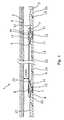
Annular barriers 1 according to the present invention are typically mounted into the well tubular structure string before lowering the welltubular structure 3 into the borehole downhole. The welltubular structure 3 is constructed by well tubular structure parts put together as a long well tubular structure string. Often, theannular barriers 1 are mounted in between the well tubular structure parts when mounting the well tubular structure string.- The
annular barrier 1 is used for a variety of purposes, all of which require that anexpandable sleeve 6 of theannular barrier 1 is expanded so that the sleeve abuts theinside wall 4 of the borehole. Theannular barrier 1 comprises atubular part 5 which is connected to the welltubular structure 3 as shown inFig. 1 , e.g. by means of athread connection 15. Thus, thetubular part 5 and the welltubular structure part 3 together form theinside wall 16 of the well tubular structure. Theannular barrier 1 ofFig. 1 is shown in its unexpanded and relaxed position creating acavity 12 between theexpandable sleeve 6 and thetubular part 5 of theannular barrier 1. In order to expand theexpandable sleeve 6, pressurised fluid is injected into thecavity 12 until the expandable sleeve abuts theinside wall 4 of the borehole. - In this embodiment, the
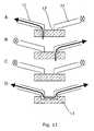
annular barrier 1 has avalve 13 which is shown in its closed position. This embodiment of thevalve 13 has four positions as shown inFig. 11 . In position A, thevalve 13 has anopen passage 11 from the inside of the welltubular structure 3 to thespace 12 between theexpandable sleeve 6 and thetubular part 5 while having aclosed passage 21 from the inside of the well tubular structure to theannulus 2 between theoutside wall 17 of the well tubular structure and theinside wall 4 of the borehole or formation. In position B, thepassage 11 from the inside of the welltubular structure 3 to thespace 12 between theexpandable sleeve 6 and thetubular part 5 is closed while thepassage 21 from the inside of the well tubular structure to theannulus 2 between theoutside wall 17 of the well tubular structure and theinside wall 4 of the borehole or formation is open. In its closed position C, thevalve 13 also closes thepassage 21 from the inside of the welltubular structure 3 to theannulus 2 between theoutside wall 17 of the well tubular structure and theinside wall 4 of the borehole or formation. In position D, thevalve 13 has anopen passage 11 from the inside of the welltubular structure 3 to thespace 12 between theexpandable sleeve 6 and thetubular part 5 while also having anopen passage 21 from the inside of the well tubular structure to theannulus 2 between theoutside wall 17 of the well tubular structure and theinside wall 4 of the borehole or formation. Thus, the position D results in a fluid connection from theannulus 2 to thespace 12. - Having a
valve 13 in theannular barrier 1 enables other fluids than cement, such as the fluid present in the well or sea water, to be used for expanding theexpandable sleeve 6 of the annular barrier. - The
expandable sleeve 6 is fastened in a fastening means 8 of aconnection part 9 of theannular barrier 1. Theexpandable sleeve 6 is fixedly fastened in the fastening means so that theends 7 of the expandable sleeve do not move in relation to the fastening means 8. Furthermore, in this embodiment, the fastening means 8 is a part of theconnection part 9. In another embodiment, the fastening means 8 is fixedly connected to theconnection part 9. Thus, both of the fastening means 8 may be fixedly fastened to itsconnection part 9 or be a part of its connection part. - As can be seen, the
expandable sleeve 6 is a thin-walled tubular structure inserted into the fastening means 8. Subsequently, the fastening means 8 has been embossed changing the form of the fastening means and theends 7 of the expandable sleeve, thus mechanically fastening them in relation to one another. In order to seal the connection between theexpandable sleeve 6 and the fastening means 8, a sealingelement 14 is arranged between them. - The
tubular part 5 of theannular barrier 1 is mounted from twoend parts 22 and anintermediate part 23 which have been joined by means of threads. In this embodiment, theend parts 22 are the same as theconnection parts 9. However, in another embodiment, theends parts 22 are fixedly connected to theconnection parts 9. - Another embodiment of the
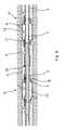
annular barrier 1 is shown inFig. 2 . In one end of theannular barrier 1, the fastening means 8 in which thesleeve 6 is fastened is slidably connected to the connection part 9 (illustrated by the arrows). When theexpandable sleeve 6 is expanded in a transverse direction, the sleeve will tend to shorten in its longitudinal direction - if possible. By having a slidable connection, thesleeve 6 is allowed to reduce its longitudinal extension, resulting in a possibly larger expansion since the sleeve is not stretched as much as when the sleeve is fixedly connected to theconnection part 9. - In order to seal the slidable connection also during any sliding movements, sealing
elements 14 are arranged between the sliding fastening means 8 and theconnection part 9. - In
Fig. 2 , theannular barrier 1 has onevalve 13 arranged in theconnection part 9 of the annular barrier in the transition between thecavity 12 and theannulus 3. In another embodiment, theconnection part 9 of the sliding connection may also be provided with avalve 13. Thus, thepassages - An
annular barrier 1 with a slidable connection between thesleeve 6 and theconnection part 9 results in an increase of the expansion ability of the sleeve with up to 100% in relation to an annular barrier without any slidable connections. - In another embodiment, the
annular barrier 1 has two slidable connections, increasing the expansion ability of thesleeve 6 even more. - In
Fig. 3 , theannular barrier 1 of the invention has avalve 13 which is slidable between a position where thefirst passage 11 from the inside of the welltubular structure 3 and thecavity 12 is open and thesecond passage 21 from the inside of the well tubular structure and theannulus 2 is closed to a second position where the first passage is closed and the second is open. As shown, thevalve 13 also has a third position in which bothpassages - In
Fig. 3 , theexpandable sleeve 6 is in its expanded condition and the unexpanded condition of the expandable sleeve is illustrated by a dotted line. As can be seen, in its unexpanded position, theexpandable sleeve 6 follows the surface of thetubular part 5 so that only anarrow space 12 is created between the two. Thetubular part 5 thus does not have any indentation, and thecavity 12 is created solely by expansion of thesleeve 6. - As can be seen from
Fig. 4 , theannular barrier 1 may also have avalve 13 placed in the part between the twoconnection parts 9. Such a valve may be a two-way valve. - Also, the
valve 13 of theannular barrier 1 may be a three-way valve which in a first position lets fluid into thespace 12 between theexpandable sleeve 6 and thetubular part 5, in a second position lets fluid into theannulus 2 between the welltubular structure 3 and the borehole, and in a third position stops the fluid from flowing. - The
expandable sleeve 6 of theannular barrier 1 has a length extending along the longitudinal extension of the welltubular structure 3. Theexpandable sleeve 6 has a wall thickness which is thinner than its length. In one embodiment, theexpandable sleeve 6 has a thickness of less than 25% of its length, preferably less than 15% of its length, more preferably less than 10% of its length. - When the
expandable sleeve 6 of theannular barrier 1 is expanded, the diameter of the sleeve is expanded from its initial unexpanded diameter to a larger diameter. In an embodiment of the invention, theexpandable sleeve 6 is capable of expanding to a diameter which is at least 10% larger than its initial diameter, preferably at least 15% larger, more preferably at least 30% larger. - In one embodiment of the
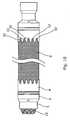
annular barrier 1, the fastening means 8 may have a projecting edge part which projects outwards from the connectingpart 9. The projection edge part may also be in the form oftongues 32 as shown inFig. 9 or10 . Having a part of the fastening means 8 bending outwards means that the fastening means does not have a sharp edge which may cause thesleeve 6 to crack close to the fastening means when expanded. - The
expandable sleeve 6 of theannular barrier 1 may be made of metal or polymers, such as an elastomeric material, silicone, or natural or syntactic rubber. - When expanding the
expandable sleeve 6, the expandable sleeve often expands in an uneven way and it is therefore manufactured having a varying wall thickness in order to compensate for the uneven expansion. - The
expandable sleeve 6 is often made of metal and, in order to improve the sealing ability of the expandable sleeve towards the inside wall of the borehole, the expandable sleeve may be provided with sealing rings 33, such as rings of polymers, rubber, silicone, or the like sealing material. - Also, the
expandable sleeve 6 may comprise a mesh, as shown inFig. 10 , to protect the sleeve from damage when being run into the well along with the welltubular structure 3. - Furthermore, the invention relates to an annular barrier system 100 comprising the above-mentioned
annular barrier 1. Such as annular barrier system 100 is shown inFig. 5 , where the annular barrier system comprises a tool 20 for expanding theexpandable sleeve 6 of theannular barrier 1. The tool 20 expands theexpandable sleeve 6 by applying a pressurised fluid through apassage 11 in thetubular part 5 into thespace 12 between the expandable sleeve and the tubular part. - In this embodiment, the tool 20 comprises an
isolation device 18 for isolating afirst section 24 outside thepassage outside wall 30 of the tool and theinside wall 16 of the well tubular structure. The pressurised fluid is created by increasing the pressure of the fluid in theisolation device 18. By isolating asection 24 of the welltubular structure 3 outside thepassage tubular part 5, the fluid in the whole well tubular structure no longer has to be pressurised and no additional plug is needed as is the case in prior art solutions. - In order to isolate the
isolated section 24, the tool 20 comprises at least one sealing means 25 for sealing against the inside wall of the welltubular structure 3 on each side of thevalve 13 in order to isolate thefirst section 24 inside the well tubular structure. The sealing means 8 is shown as two separate sealing means, but may as well be just one means which is expandable in two positions. The sealing means 8 may be made of an expandable polymer which is inflated by the well fluid or a gas comprised in a reservoir in the tool 20. When theisolation device 18 is no longer needed, the sealing means 8 is deflated and the tool 20 may be retracted. - In that it is able to isolate a
section 24 in the welltubular structure 3, this tool 20 can be used for injecting cement into the cavity in known annular barriers in order to expand the expandable sleeves of known annular barriers. In this case, no valve is needed due to the fact that the cement hardens and the cavity thus does not have to be closed in order to keep the cement inside the cavity. - In another embodiment, the pressurised fluid is well fluid, i.e. the fluid present in the well
tubular structure 3, and the tool 20 has a suction means for suction of fluid into the tool and out into theisolated section 24 or directly into thepassage - When the tool 20 has expanded the
expandable sleeve 6 by pressing fluid into the space orcavity 12 between the expandable sleeve and thetubular part 5 of theannular barrier 1, thepassage 11 has to be closed in order to stop the fluid from running back into the welltubular structure 3 when the tool is retracted. In this embodiment, thepassage 11 is controlled by means of avalve 13. - In order to control the
valve 13, the tool 20 has means for adjusting the valve from one position to another position, e.g. from an open position to a closed position. In one embodiment, the means for adjusting thevalve 13 is a keyengaging indentations 34 in the valve in order to move the valve. - In
Fig. 5 , the tool 20 is shown having astroker tool 27 for letting pressurised fluid into the first section. - The annular barrier system 100 of
Fig. 5 comprises twoannular barriers 1 positioned at a distance from each other along aproduction zone 29 in the welltubular structure 3. Oneannular barrier tubular structure 3 in the borehole or in a previous run to isolate the production zone together with the secondannular barrier expandable sleeve 6 of the secondannular barrier 41, thevalves 13 of the firstannular barrier 31 are closed (illustrated by circles with a cross). - In one embodiment, the system 100 comprises a plurality of
annular barriers 1 fluidly connected by means of a fluid connection, such as a tube running on the outside of the welltubular structure 3 so that, by expanding one annular barrier, a pluralities of annular barriers can be expanded in turn. In this way, the tool 20 can expand all thesubsequent barriers 1 by injecting a pressurised fluid into the first annular barrier. Thus, the tool 20 only has to be lowered into the top part of the well and not all the way into the well. - When producing, the well
tubular structure 3 is often perforated to allow the oil fluid to flow into the well tubular structure and further on to the surface of the well. Thus, theannular barriers 1 cannot be expanded by building up a pressure within the welltubular structure 3, such as by means of coiled tubing. By linking theannular barriers 1 by a fluid connection, also annular barriers arranged below the perforations can be expanded without sealing off a zone around each annular barrier. - When linking
annular barriers 1 together via a fluid communication as mentioned, the first annular barrier is expanded in order to expand also the subsequent barriers. Thefirst barrier 1 can be expanded by a tool 20 by means of theisolation device 18 or by temporarily plugging the well beneath the first barrier and applying a pressure of fluid from the surface. - In the event that the tool 20 cannot move forward in the well
tubular structure 3, the tool may comprise a downhole tractor, such as a Well Tractor®. - The tool 20 may have
several stroker tools 27 in order to expand several expandabletubular sleeves 6 at a time. The tool 20 may have more than oneisolation device 18 and thus be able to operate severalannular barriers 1 at the same time, e.g. expandingseveral sleeves 6 or measuring the conditions of aproduction zone 29, theannulus 2, and/or the inside pressure of the expanded annular barrier. - The tool 20 may have means for measuring the flow, temperature, pressure, density, water hold-up, and/or expansion of the
sleeve 6. When measuring flow, temperature, pressure, density, and/or water hold-up, the conditions of theproduction zone 29 can be evaluated. - In order to evaluate the data from the measurements, the tool 20 has a recording and/or transmitting device for recording and/or transmitting data from measurements performed by the tool.
- It may also occur that the pressure on one side of an expanded
annular barrier 1 is larger than the pressure within thecavity 12 of the annular barrier. The fluid from the high-pressure zone HP may thus try to undermine the connection between theexpandable sleeve 6 and the inside wall of the borehole in order to equalise the pressure difference. In this case, thetool 30 opens thevalve 13 of theannular barrier 1, allowing fluid to flow from the high-pressure zone into the annular barrier as shown inFig. 7 . In this way, it is ensured that the fluid from a high-pressure zone does not break the seal between the expandedannular barrier 1 and the inside wall of the borehole. - The tool 20 of
Fig. 6 uses coiled tubing for expanding theexpandable sleeve 6 of twoannular barriers 1 at the same time. A tool 20 with coiled tubing can pressurise the fluid in the welltubular structure 3 without having to isolate asection 24 of the well tubular structure; however, the tool may need to plug the well tubular structure further down the borehole from the twoannular barriers 1 to be operated. - The annular barrier system 100 of the present invention may also expand the
sleeve 6 by means of a drill pipe or a wireline tool, such as the one shown inFig. 5 . - The annular barrier system 100 may comprise an
anchor tool 26 for anchoring of the tool 20 inside the welltubular structure 3 when operating theannular barriers 1, as shown inFig. 5 . - In one embodiment, the tool 20 comprises a reservoir containing the pressurised fluid, e.g. when the fluid used for expanding the
sleeve 6 is cement, gas, or a two-component compound. - In
Fig. 6 , twoannular barriers 1 are inflated simultaneously into having a pressure higher than that of theannulus 2. Hereby, it is ensured that theannular barriers 1 seal properly against the inside wall of the borehole. The flow of the pressurised fluid is illustrated by arrows. When theannular barriers 1 have been expanded, the welltubular structure 3 is centralised in the borehole and ready to use for production of oil. - The
annular barriers 1 during production are shown inFig. 7 , where thevalves 13 of the annular barriers have been closed and theproduction valve 35 is in fluid communication with the production screen and thus theproduction zone 29 of the formation. During production, thevalves 13 controlling the passage from the non-production zone of theannulus 2 and thecavity 12 are opened so that the pressure of well fluid in the cavity is the same as the pressure of well fluid in the non-production zone. The arrow inside the welltubular structure 3 illustrates the flow of oil. This ensures that the highest pressure in relation to the formation pressure is maintained within thecavity 12, thereby reducing the differential pressure across theexpandable sleeve 6. - The
annular barriers 1 of the present invention may also be used when fracturing the formation in order to enable oil to run out of the formation at a higher rate. Anannular barrier 1 is expanded on each side of thefuture production zone 29. Pressurised well fluid or water is injected through theproduction valve 35 and thus through theproduction screen 29 in order to crack and penetrate the formation. While fracturing, one of thevalves 13 in eachannular barrier 1 is adjusted so that the pressurised fluid in the fracturing zone also flows into thecavity 12 of theannular barriers 1, reducing the risk of the fluid undermining the seal between thesleeve 6 and the inside wall of the borehole, and also reducing the risk of the expandable sleeve collapsing inwards. Theother valve 13 in eachannular barrier 1 is kept closed. - An
annular barrier 1 may also be called a packer or the like expandable means. The welltubular structure 3 can be the production tubing or casing or a similar kind of tubing downhole in a well or a borehole. Theannular barrier 1 can be used both in between the inner production tubing and an outer tubing in the borehole or between a tubing and the inner wall of the borehole. A well may have several kinds of tubing and theannular barrier 1 of the present invention can be mounted for use in all of them. - The
valve 13 may be any kind of valve capable of controlling flow, such as a ball valve, butterfly valve, choke valve, check valve or non-return valve, diaphragm valve, expansion valve, gate valve, globe valve, knife valve, needle valve, piston valve, pinch valve, or plug valve. - The expandable
tubular metal sleeve 6 may be a cold-drawn or hot-drawn tubular structure. - The fluid used for expanding the
expandable sleeve 6 may be any kind of well fluid present in the borehole surrounding the tool 20 and/or the welltubular structure 3. Also, the fluid may be cement, gas, water, polymers, or a two-component compound, such as powder or particles mixing or reacting with a binding or hardening agent. - The means for measuring the flow, temperature, pressure, density, water hold-up, and/or expansion of the
sleeve 6 may be any kind of sensors. The sensor for measuring the expansion of thesleeve 6 may be e.g. a strain gauge. - The recording device may have a memory. The transmitting device may transmit data by means of wireless communication, fibre optic, wireline, or fluid telemetry.
- Although the invention has been described in the above in connection with preferred embodiments of the invention, it will be evident for a person skilled in the art that several modifications are conceivable without departing from the invention as defined by the following claims.
Claims (17)
- Annular barrier (1) comprising a tubular part (5) for mounting as part of a well tubular structure (3) in a borehole, the annular barrier comprising an expandable sleeve (6) surrounding the tubular part, each end (7) of the expandable sleeve being fastened in a fastening means (8) of a connection part (9) in the tubular part, and a valve (13) for controlling the passage of pressurised fluid into a space (12) between the expandable sleeve and the tubular part,
characterised in that
the valve is a two-way valve. - Annular barrier according to claim 1, wherein the valve is positioned in at least one of the connection parts.
- Annular barrier according to claim 1 or 2, wherein the valve is a three-way valve for, in a first position, letting fluid into the space between the expandable sleeve and the tubular part, in a second position letting fluid into the annulus between the well tubular structure and the borehole, and in a third position stopping the fluid from flowing.
- Annular barrier according to claim 1 or 2, wherein the valve in a first position lets fluid into the space between the expandable sleeve and the tubular part, in a second position lets fluid into the annulus between the well tubular structure and the borehole, in a third position stops the fluid from flowing, and in a fourth position lets fluid flow between the annulus and the space.
- Annular barrier according to any one of the preceding claims, wherein at least one of the fastening means is slidable in relation to the connection part of the tubular part of the annular barrier.
- Annular barrier according to any one of the preceding claims, wherein at least one of the fastening means is fixedly fastened to the connection part or at least one of the fastening means is part of the connection part.
- Annular barrier system (100) for expanding an annular barrier (1) according to any one of the claims 1-5 in an annulus (2) between a well tubular structure (3) and an inside wall (4) of a borehole downhole,
characterised in that the system comprises:- a tool (20) for expanding the expandable sleeve by letting a pressurised fluid through a passage (11, 21) in the tubular part into a space (12) between the expandable sleeve and the tubular part. - Annular barrier system according to claim 7, wherein the system comprises at least two annular barriers positioned at a distance from each other along the well tubular structure.
- Annular barrier system according to claim 8, wherein the at least two annular barriers are fluidly connected via a fluid connection.
- Annular barrier system according to any one of the claims 7-9, wherein the tool has means for adjusting the valve from one position to another.
- Annular barrier system according to any one of the claims 7-10, wherein the tool has an isolation device (18) for isolating a first section (24) between an outside wall of the tool (30) and an inside wall of the well tubular structure (11) outside the passage of the tubular part.
- Annular barrier system according to claim 11, wherein the isolation device of the tool has at least one sealing means (25) for sealing against the inside wall of the well tubular structure on each side of the valve in order to isolate the first section inside the well tubular structure.
- Annular barrier system according to any one of the claims 7-12, wherein the tool has a pressure delivering means (27) for taking in fluid from the borehole and for delivering pressurised fluid to the first section.
- Use of the annular barrier according to any one of the claims 1-6 in a well tubular structure for insertion into a borehole.
- Tool (20) for expanding an expandable sleeve by letting a pressurised fluid through a passage (11, 21) in a tubular part into a space (12) between the expandable sleeve and the tubular part in the annular barrier system according to any one of claims 7-13, wherein the tool has means for adjusting the valve from one position to another, or
the tool has an isolation device (18) for isolating a first section (24) between an outside wall of the tool (30) and an inside wall of the well tubular structure (11) outside the passage of the tubular part, or
the tool has a pressure delivering means (27) for taking in fluid from the borehole and for delivering pressurised fluid to the first section. - Expansion method for expanding an annular barrier according to any one of the claims 1-6 inside a borehole comprising a well fluid having a pressure, the method comprising the steps of:- placing a tool outside the passage of the tubular part of the annular barrier,- isolating the passage by means of the isolation device of the tool, and- increasing the pressure of the well fluid inside the isolation device in order to expand the sleeve of the annular barrier,
or the steps of:- placing a tool outside the passage of the tubular part of the annular barrier, and- opening the valve in the connection part of the annular barrier so that pressurised fluid in coiled tubing, in a chamber in the tool, or in an isolated section between an outside wall of the tool and an inside wall of the well tubular structure is let into the space between the tubular part and the expandable sleeve of the annular barrier in order to expand the sleeve. - Production method for producing oil or the like fluid through a well tubular structure having a production zone (29) in which the well tubular structure has perforations, a screen, or the like and at least two annular barriers according to any one of the claims 1-6, comprising the steps of:- expanding a first annular barrier (31) at one side of the production zone of the well tubular structure,- expanding a second annular barrier (41) at another of the production zone of the well tubular structure, and- letting fluid into the well tubular structure through the production zone.
Priority Applications (17)
| Application Number | Priority Date | Filing Date | Title |
|---|---|---|---|
| EP20090150385EP2206879B1 (en) | 2009-01-12 | 2009-01-12 | Annular barrier and annular barrier system |
| ES09150385TES2464457T3 (en) | 2009-01-12 | 2009-01-12 | Annular barrier and annular barrier system |
| MX2011006115AMX2011006115A (en) | 2009-01-12 | 2010-01-12 | Annular barrier and annular barrier system. |
| CA2853370ACA2853370C (en) | 2009-01-12 | 2010-01-12 | Annular barrier and annular barrier system |
| CN201410244850.6ACN104100225B (en) | 2009-01-12 | 2010-01-12 | annular barrier and annular barrier system |
| EP10700124.0AEP2391796B1 (en) | 2009-01-12 | 2010-01-12 | Annular barrier and annular barrier system |
| BRPI1006151-7ABRPI1006151B1 (en) | 2009-01-12 | 2010-01-12 | annular barrier, annular barrier system, expansion method to expand an annular barrier and production method |
| AU2010204282AAU2010204282B2 (en) | 2009-01-12 | 2010-01-12 | Annular barrier and annular barrier system |
| CN201080004299.8ACN102272413B (en) | 2009-01-12 | 2010-01-12 | Annular barrier and annular barrier system |
| US13/138,139US9080415B2 (en) | 2009-01-12 | 2010-01-12 | Annular barrier and annular barrier system |
| PCT/EP2010/050298WO2010079237A1 (en) | 2009-01-12 | 2010-01-12 | Annular barrier and annular barrier system |
| BR122014014688-4ABR122014014688B1 (en) | 2009-01-12 | 2010-01-12 | annular barrier system, expansion method to expand an annular barrier, and production method to produce oil or similar fluid through a tubular well structure |
| CA2746015ACA2746015C (en) | 2009-01-12 | 2010-01-12 | Annular barrier and annular barrier system |
| DKPA201070395ADK178851B1 (en) | 2009-01-12 | 2010-09-13 | Annular barrier and annular barrier system and method |
| US14/318,824US9745819B2 (en) | 2009-01-12 | 2014-06-30 | Annular barrier and annular barrier system |
| DKPA201600758ADK179865B1 (en) | 2009-01-12 | 2016-12-09 | Annular barrier and annular barrier system and method |
| US15/668,784US10202819B2 (en) | 2009-01-12 | 2017-08-04 | Annular barrier and annular barrier system |
Applications Claiming Priority (1)
| Application Number | Priority Date | Filing Date | Title |
|---|---|---|---|
| EP20090150385EP2206879B1 (en) | 2009-01-12 | 2009-01-12 | Annular barrier and annular barrier system |
Publications (2)
| Publication Number | Publication Date |
|---|---|
| EP2206879A1 EP2206879A1 (en) | 2010-07-14 |
| EP2206879B1true EP2206879B1 (en) | 2014-02-26 |
Family
ID=40765793
Family Applications (2)
| Application Number | Title | Priority Date | Filing Date |
|---|---|---|---|
| EP20090150385RevokedEP2206879B1 (en) | 2009-01-12 | 2009-01-12 | Annular barrier and annular barrier system |
| EP10700124.0ANot-in-forceEP2391796B1 (en) | 2009-01-12 | 2010-01-12 | Annular barrier and annular barrier system |
Family Applications After (1)
| Application Number | Title | Priority Date | Filing Date |
|---|---|---|---|
| EP10700124.0ANot-in-forceEP2391796B1 (en) | 2009-01-12 | 2010-01-12 | Annular barrier and annular barrier system |
Country Status (10)
| Country | Link |
|---|---|
| US (3) | US9080415B2 (en) |
| EP (2) | EP2206879B1 (en) |
| CN (2) | CN104100225B (en) |
| AU (1) | AU2010204282B2 (en) |
| BR (2) | BRPI1006151B1 (en) |
| CA (2) | CA2853370C (en) |
| DK (2) | DK178851B1 (en) |
| ES (1) | ES2464457T3 (en) |
| MX (1) | MX2011006115A (en) |
| WO (1) | WO2010079237A1 (en) |
Cited By (3)
| Publication number | Priority date | Publication date | Assignee | Title |
|---|---|---|---|---|
| RU2719852C2 (en)* | 2010-12-17 | 2020-04-23 | Веллтек Ойлфилд Солюшнс АГ | Well completion |
| EP3914802A1 (en)* | 2019-01-23 | 2021-12-01 | Saltel Industries | Expandable metal packer with anchoring system |
| EP3914803B1 (en)* | 2019-01-23 | 2025-04-02 | Saltel Industries | Expandable metal packer system with pressure control device |
Families Citing this family (83)
| Publication number | Priority date | Publication date | Assignee | Title |
|---|---|---|---|---|
| ES2464457T3 (en) | 2009-01-12 | 2014-06-02 | Welltec A/S | Annular barrier and annular barrier system |
| GB0909086D0 (en) | 2009-05-27 | 2009-07-01 | Read Well Services Ltd | An active external casing packer (ecp) for frac operations in oil and gas wells |
| DK2436874T3 (en)* | 2010-09-30 | 2013-10-07 | Welltec As | Drill pipe |
| WO2012045355A1 (en)* | 2010-10-07 | 2012-04-12 | Welltec A/S | An annular barrier |
| EP3216976A1 (en)* | 2010-10-07 | 2017-09-13 | Welltec A/S | An annular barrier |
| US8770305B2 (en)* | 2010-11-22 | 2014-07-08 | Boise State University | Modular hydraulic packer-and-port system |
| AU2013100365C4 (en)* | 2010-12-17 | 2015-11-26 | Welltec Oilfield Solutions Ag | Well completion |
| CN102155251A (en)* | 2011-02-28 | 2011-08-17 | 河南理工大学 | Waterpower hole packer |
| EP2538018A1 (en)* | 2011-06-23 | 2012-12-26 | Welltec A/S | An annular barrier with external seal |
| EP3106604A1 (en)* | 2011-08-31 | 2016-12-21 | Welltec A/S | Downhole system and method for fastening upper and lower casings via expandable metal sleeve |
| EP2565368A1 (en)* | 2011-08-31 | 2013-03-06 | Welltec A/S | Annular barrier with pressure amplification |
| EP2570587B1 (en) | 2011-09-13 | 2013-10-30 | Welltec A/S | Annular barrier with safety metal sleeve |
| EP2599956A1 (en)* | 2011-11-30 | 2013-06-05 | Welltec A/S | Annular barrier system with flow lines |
| EP2607614B1 (en)* | 2011-12-21 | 2014-10-15 | Welltec A/S | An annular barrier with an expansion detection device |
| EP2607613A1 (en)* | 2011-12-21 | 2013-06-26 | Welltec A/S | An annular barrier with a self-actuated device |
| US9010416B2 (en)* | 2012-01-25 | 2015-04-21 | Baker Hughes Incorporated | Tubular anchoring system and a seat for use in the same |
| CA3076393C (en)* | 2012-03-07 | 2023-03-28 | Halliburton Manufacturing And Services Limited | Downhole apparatus |
| FR2988126B1 (en) | 2012-03-16 | 2015-03-13 | Saltel Ind | DEVICE FOR INSULATING A PART OF A WELL |
| EP2828471A2 (en)* | 2012-03-21 | 2015-01-28 | Saudi Arabian Oil Company | Inflatable collar and downhole method for moving a coiled tubing string |
| CN104781501B (en)* | 2012-08-28 | 2017-07-28 | 哈里伯顿能源服务公司 | Expandable tieback seal assembly |
| FR2996247B1 (en)* | 2012-10-03 | 2015-03-13 | Saltel Ind | HYDRAULIC FRACTURING METHOD AND CORRESPONDING EQUIPMENT |
| US20140262290A1 (en)* | 2013-03-14 | 2014-09-18 | Baker Hughes Incorpoarated | Method and system for treating a borehole |
| EP2789791A1 (en) | 2013-04-12 | 2014-10-15 | Welltec A/S | A downhole expandable tubular |
| EP2789792A1 (en) | 2013-04-12 | 2014-10-15 | Welltec A/S | A downhole expandable tubular |
| GB2517202B (en) | 2013-08-16 | 2020-03-18 | Morphpackers Ltd | Improved filling mechanism for a morphable sleeve |
| EP2876251A1 (en)* | 2013-11-21 | 2015-05-27 | Welltec A/S | Annular barrier with passive pressure compensation |
| EP2878763A1 (en)* | 2013-11-29 | 2015-06-03 | Welltec A/S | A downhole casing string |
| FR3016389B1 (en) | 2014-01-10 | 2016-01-08 | Saltel Ind | ISOLATION DEVICE FOR WELLS |
| JP6526185B2 (en) | 2014-09-30 | 2019-06-05 | アップル インコーポレイテッドApple Inc. | Loudspeaker with reduced audio coloration caused by surface reflections |
| USRE49437E1 (en) | 2014-09-30 | 2023-02-28 | Apple Inc. | Audio driver and power supply unit architecture |
| US10609473B2 (en) | 2014-09-30 | 2020-03-31 | Apple Inc. | Audio driver and power supply unit architecture |
| GB201417671D0 (en)* | 2014-10-07 | 2014-11-19 | Meta Downhole Ltd | Improved isolation barrier |
| EP3073050A1 (en) | 2015-03-27 | 2016-09-28 | Welltec A/S | A downhole well tubular structure |
| US10408012B2 (en) | 2015-07-24 | 2019-09-10 | Innovex Downhole Solutions, Inc. | Downhole tool with an expandable sleeve |
| US10156119B2 (en) | 2015-07-24 | 2018-12-18 | Innovex Downhole Solutions, Inc. | Downhole tool with an expandable sleeve |
| EP3159478A1 (en)* | 2015-10-23 | 2017-04-26 | Welltec A/S | Downhole completion system sealing against the cap layer |
| RU2726710C2 (en)* | 2015-08-17 | 2020-07-15 | Веллтек Ойлфилд Солюшнс АГ | Well completion system providing tightness relative to coating layer |
| JP6620286B2 (en)* | 2015-12-15 | 2019-12-18 | 帝石削井工業株式会社 | Packer |
| EP3408494B1 (en)* | 2016-01-26 | 2021-02-24 | Welltec Oilfield Solutions AG | Annular barrier and downhole system for low pressure zone |
| EP3255240A1 (en) | 2016-06-10 | 2017-12-13 | Welltec A/S | Downhole straddle system |
| US10631071B2 (en) | 2016-09-23 | 2020-04-21 | Apple Inc. | Cantilevered foot for electronic device |
| EP3526440B1 (en)* | 2016-10-12 | 2023-11-08 | Welltec Oilfield Solutions AG | Expansion assembly |
| EP3327246A1 (en)* | 2016-11-25 | 2018-05-30 | Welltec A/S | Annular barrier with expansion verification |
| US10227842B2 (en) | 2016-12-14 | 2019-03-12 | Innovex Downhole Solutions, Inc. | Friction-lock frac plug |
| US10316619B2 (en) | 2017-03-16 | 2019-06-11 | Saudi Arabian Oil Company | Systems and methods for stage cementing |
| EP3601718B1 (en)* | 2017-03-27 | 2021-06-16 | Saltel Industries | Expandable metal packer system and methodology with annulus pressure compensation |
| US10544648B2 (en) | 2017-04-12 | 2020-01-28 | Saudi Arabian Oil Company | Systems and methods for sealing a wellbore |
| US10557330B2 (en) | 2017-04-24 | 2020-02-11 | Saudi Arabian Oil Company | Interchangeable wellbore cleaning modules |
| AU2018308919B2 (en)* | 2017-07-27 | 2021-05-27 | Welltec Manufacturing Center Completions ApS | Annular barrier for small diameter wells |
| EP3480421A1 (en)* | 2017-11-06 | 2019-05-08 | Welltec Oilfield Solutions AG | Annular barrier for small diameter wells |
| US10487604B2 (en) | 2017-08-02 | 2019-11-26 | Saudi Arabian Oil Company | Vibration-induced installation of wellbore casing |
| US10378298B2 (en) | 2017-08-02 | 2019-08-13 | Saudi Arabian Oil Company | Vibration-induced installation of wellbore casing |
| US10597962B2 (en) | 2017-09-28 | 2020-03-24 | Saudi Arabian Oil Company | Drilling with a whipstock system |
| US10378339B2 (en) | 2017-11-08 | 2019-08-13 | Saudi Arabian Oil Company | Method and apparatus for controlling wellbore operations |
| EP3495602A1 (en)* | 2017-12-07 | 2019-06-12 | Welltec Oilfield Solutions AG | Downhole repairing system |
| CN107916908A (en)* | 2017-12-11 | 2018-04-17 | 中国石油天然气股份有限公司 | In-pipe composite sealing mechanism |
| CN110273652B (en)* | 2018-03-14 | 2021-06-01 | 中国石油天然气股份有限公司 | Oil production well acid pickling pipe column structure and acid pickling method of oil production well |
| US10689913B2 (en) | 2018-03-21 | 2020-06-23 | Saudi Arabian Oil Company | Supporting a string within a wellbore with a smart stabilizer |
| US10689914B2 (en) | 2018-03-21 | 2020-06-23 | Saudi Arabian Oil Company | Opening a wellbore with a smart hole-opener |
| GB2572449B (en)* | 2018-03-30 | 2020-09-16 | Morphpackers Ltd | Improved isolation barrier |
| US10794170B2 (en) | 2018-04-24 | 2020-10-06 | Saudi Arabian Oil Company | Smart system for selection of wellbore drilling fluid loss circulation material |
| US10612362B2 (en) | 2018-05-18 | 2020-04-07 | Saudi Arabian Oil Company | Coiled tubing multifunctional quad-axial visual monitoring and recording |
| CN109138933B (en)* | 2018-07-27 | 2020-11-06 | 中国石油天然气股份有限公司 | Elastic screen pipe and sand control pipe column |
| US10989016B2 (en) | 2018-08-30 | 2021-04-27 | Innovex Downhole Solutions, Inc. | Downhole tool with an expandable sleeve, grit material, and button inserts |
| CN109138880B (en)* | 2018-10-27 | 2023-10-20 | 长葛市金博机械化工有限公司 | Bidirectional anchor |
| US11125039B2 (en) | 2018-11-09 | 2021-09-21 | Innovex Downhole Solutions, Inc. | Deformable downhole tool with dissolvable element and brittle protective layer |
| US11965391B2 (en) | 2018-11-30 | 2024-04-23 | Innovex Downhole Solutions, Inc. | Downhole tool with sealing ring |
| US11396787B2 (en) | 2019-02-11 | 2022-07-26 | Innovex Downhole Solutions, Inc. | Downhole tool with ball-in-place setting assembly and asymmetric sleeve |
| US11261683B2 (en) | 2019-03-01 | 2022-03-01 | Innovex Downhole Solutions, Inc. | Downhole tool with sleeve and slip |
| US11203913B2 (en) | 2019-03-15 | 2021-12-21 | Innovex Downhole Solutions, Inc. | Downhole tool and methods |
| US11634964B2 (en) | 2019-07-16 | 2023-04-25 | Halliburton Energy Services, Inc. | Swellable rubber element that also creates a cup packer |
| US11572753B2 (en) | 2020-02-18 | 2023-02-07 | Innovex Downhole Solutions, Inc. | Downhole tool with an acid pill |
| US11299968B2 (en) | 2020-04-06 | 2022-04-12 | Saudi Arabian Oil Company | Reducing wellbore annular pressure with a release system |
| US11396789B2 (en) | 2020-07-28 | 2022-07-26 | Saudi Arabian Oil Company | Isolating a wellbore with a wellbore isolation system |
| US11414942B2 (en) | 2020-10-14 | 2022-08-16 | Saudi Arabian Oil Company | Packer installation systems and related methods |
| EP3992420A1 (en)* | 2020-10-30 | 2022-05-04 | Welltec Oilfield Solutions AG | Downhole packer assembly |
| CN112665473A (en)* | 2020-12-10 | 2021-04-16 | 中煤科工开采研究院有限公司 | Blasting hole sealing method |
| US11624265B1 (en) | 2021-11-12 | 2023-04-11 | Saudi Arabian Oil Company | Cutting pipes in wellbores using downhole autonomous jet cutting tools |
| US12286845B2 (en) | 2022-04-26 | 2025-04-29 | Downhole Products Limited | Slimline stop collar with seal to prevent micro-annulus leakage |
| CN114934756B (en)* | 2022-06-28 | 2024-01-05 | 中核通辽铀业有限责任公司 | Well plugging structure, layered liquid extraction amount measuring device and measuring method thereof |
| US20250084736A1 (en)* | 2023-09-08 | 2025-03-13 | Welltec Manufacturing Center Completions ApS | Annular barrier and downhole system |
| CN117166950B (en)* | 2023-10-23 | 2025-08-15 | 西南石油大学 | Flexible cone sleeve expansion tool and sleeve expansion method |
| CN117345173B (en)* | 2023-11-22 | 2024-05-10 | 中国矿业大学(北京) | A high-pressure gas extraction method |
Citations (1)
| Publication number | Priority date | Publication date | Assignee | Title |
|---|---|---|---|---|
| US7306033B2 (en)* | 2004-08-04 | 2007-12-11 | Read Well Services Limited | Apparatus for isolating zones in a well |
Family Cites Families (22)
| Publication number | Priority date | Publication date | Assignee | Title |
|---|---|---|---|---|
| US4230180A (en)* | 1978-11-13 | 1980-10-28 | Westbay Instruments Ltd. | Isolating packer units in geological and geophysical measuring casings |
| US4260164A (en) | 1979-06-15 | 1981-04-07 | Halliburton Company | Inflatable packer assembly with control valve |
| US4349204A (en)* | 1981-04-29 | 1982-09-14 | Lynes, Inc. | Non-extruding inflatable packer assembly |
| US4499947A (en)* | 1983-12-12 | 1985-02-19 | Magyar Szenhidrogenipari Kutatofejleszto Intezet | Packer for separation of zones in a well bore |
| US4714117A (en) | 1987-04-20 | 1987-12-22 | Atlantic Richfield Company | Drainhole well completion |
| US5109925A (en) | 1991-01-17 | 1992-05-05 | Halliburton Company | Multiple stage inflation packer with secondary opening rupture disc |
| US5271469A (en) | 1992-04-08 | 1993-12-21 | Ctc International | Borehole stressed packer inflation system |
| CA2169382C (en) | 1996-02-13 | 2003-08-05 | Marvin L. Holbert | Method and apparatus for use in inflating packer in well bore |
| US5711372A (en) | 1996-05-21 | 1998-01-27 | Tam International | Inflatable packer with port collar valving and method of setting |
| US6253857B1 (en)* | 1998-11-02 | 2001-07-03 | Halliburton Energy Services, Inc. | Downhole hydraulic power source |
| FR2791732B1 (en) | 1999-03-29 | 2001-08-10 | Cooperation Miniere Et Ind Soc | BLOCKING DEVICE OF A WELLBORE |
| US6325144B1 (en) | 2000-06-09 | 2001-12-04 | Baker Hughes, Inc. | Inflatable packer with feed-thru conduits |
| US6854522B2 (en) | 2002-09-23 | 2005-02-15 | Halliburton Energy Services, Inc. | Annular isolators for expandable tubulars in wellbores |
| GB0303422D0 (en) | 2003-02-13 | 2003-03-19 | Read Well Services Ltd | Apparatus and method |
| US7347274B2 (en)* | 2004-01-27 | 2008-03-25 | Schlumberger Technology Corporation | Annular barrier tool |
| CN2707948Y (en)* | 2004-06-10 | 2005-07-06 | 潘昌德 | Hydropneumatic packer |
| US20060042801A1 (en) | 2004-08-24 | 2006-03-02 | Hackworth Matthew R | Isolation device and method |
| US7284619B2 (en) | 2005-02-02 | 2007-10-23 | Tam International, Inc. | Packer with positionable collar |
| CN2779052Y (en)* | 2005-04-14 | 2006-05-10 | 赵志诚 | Automatic sealing / unsealing water well sealing equipment capable of checking seal |
| US7591321B2 (en)* | 2005-04-25 | 2009-09-22 | Schlumberger Technology Corporation | Zonal isolation tools and methods of use |
| US7757769B2 (en)* | 2007-10-04 | 2010-07-20 | Baker Hughes Incorporated | Wellbore and reservoir treatment device and method |
| ES2464457T3 (en) | 2009-01-12 | 2014-06-02 | Welltec A/S | Annular barrier and annular barrier system |
- 2009
- 2009-01-12ESES09150385Tpatent/ES2464457T3/enactiveActive
- 2009-01-12EPEP20090150385patent/EP2206879B1/ennot_activeRevoked
- 2010
- 2010-01-12CACA2853370Apatent/CA2853370C/ennot_activeExpired - Fee Related
- 2010-01-12USUS13/138,139patent/US9080415B2/enactiveActive
- 2010-01-12BRBRPI1006151-7Apatent/BRPI1006151B1/ennot_activeIP Right Cessation
- 2010-01-12BRBR122014014688-4Apatent/BR122014014688B1/ennot_activeIP Right Cessation
- 2010-01-12CACA2746015Apatent/CA2746015C/ennot_activeExpired - Fee Related
- 2010-01-12CNCN201410244850.6Apatent/CN104100225B/ennot_activeExpired - Fee Related
- 2010-01-12CNCN201080004299.8Apatent/CN102272413B/ennot_activeExpired - Fee Related
- 2010-01-12WOPCT/EP2010/050298patent/WO2010079237A1/enactiveApplication Filing
- 2010-01-12MXMX2011006115Apatent/MX2011006115A/enactiveIP Right Grant
- 2010-01-12EPEP10700124.0Apatent/EP2391796B1/ennot_activeNot-in-force
- 2010-01-12AUAU2010204282Apatent/AU2010204282B2/ennot_activeCeased
- 2010-09-13DKDKPA201070395Apatent/DK178851B1/ennot_activeIP Right Cessation
- 2014
- 2014-06-30USUS14/318,824patent/US9745819B2/enactiveActive
- 2016
- 2016-12-09DKDKPA201600758Apatent/DK179865B1/ennot_activeIP Right Cessation
- 2017
- 2017-08-04USUS15/668,784patent/US10202819B2/enactiveActive
Patent Citations (1)
| Publication number | Priority date | Publication date | Assignee | Title |
|---|---|---|---|---|
| US7306033B2 (en)* | 2004-08-04 | 2007-12-11 | Read Well Services Limited | Apparatus for isolating zones in a well |
Cited By (4)
| Publication number | Priority date | Publication date | Assignee | Title |
|---|---|---|---|---|
| RU2719852C2 (en)* | 2010-12-17 | 2020-04-23 | Веллтек Ойлфилд Солюшнс АГ | Well completion |
| EP3914802A1 (en)* | 2019-01-23 | 2021-12-01 | Saltel Industries | Expandable metal packer with anchoring system |
| EP3914803B1 (en)* | 2019-01-23 | 2025-04-02 | Saltel Industries | Expandable metal packer system with pressure control device |
| EP3914802B1 (en)* | 2019-01-23 | 2025-07-02 | Saltel Industries | Expandable metal packer with anchoring system |
Also Published As
| Publication number | Publication date |
|---|---|
| CN102272413A (en) | 2011-12-07 |
| US20110266004A1 (en) | 2011-11-03 |
| EP2391796A1 (en) | 2011-12-07 |
| BR122014014688A2 (en) | 2016-03-22 |
| DK201600758A1 (en) | 2017-02-13 |
| CA2853370A1 (en) | 2010-07-15 |
| WO2010079237A1 (en) | 2010-07-15 |
| US9080415B2 (en) | 2015-07-14 |
| CN104100225B (en) | 2017-03-29 |
| EP2206879A1 (en) | 2010-07-14 |
| DK179865B1 (en) | 2019-08-05 |
| BR122014014688B1 (en) | 2021-01-12 |
| CN102272413B (en) | 2014-07-02 |
| BRPI1006151B1 (en) | 2020-11-17 |
| AU2010204282A1 (en) | 2011-06-23 |
| ES2464457T3 (en) | 2014-06-02 |
| US20140311751A1 (en) | 2014-10-23 |
| US20170328170A1 (en) | 2017-11-16 |
| DK201070395A (en) | 2010-09-13 |
| CN104100225A (en) | 2014-10-15 |
| CA2746015C (en) | 2016-09-06 |
| EP2391796B1 (en) | 2015-02-25 |
| CA2746015A1 (en) | 2010-07-15 |
| CA2853370C (en) | 2017-06-20 |
| AU2010204282B2 (en) | 2013-07-04 |
| US9745819B2 (en) | 2017-08-29 |
| US10202819B2 (en) | 2019-02-12 |
| BRPI1006151A2 (en) | 2016-02-23 |
| DK178851B1 (en) | 2017-03-27 |
| MX2011006115A (en) | 2011-06-24 |
Similar Documents
| Publication | Publication Date | Title |
|---|---|---|
| EP2206879B1 (en) | Annular barrier and annular barrier system | |
| US8789581B2 (en) | Flow control devices on expandable tubing run through production tubing and into open hole | |
| US8091641B2 (en) | Method and apparatus to cement a perforated casing | |
| US9664024B2 (en) | Method for fracking wells using a packer to form primary and secondary fracs and seal intervals for hydraulic fracturing | |
| US20150034316A1 (en) | Annular barrier having expansion tubes | |
| CN102472086B (en) | current limiter | |
| US20230003099A1 (en) | System and Method for Cementing a Tubing |
Legal Events
| Date | Code | Title | Description |
|---|---|---|---|
| PUAI | Public reference made under article 153(3) epc to a published international application that has entered the european phase | Free format text:ORIGINAL CODE: 0009012 | |
| AK | Designated contracting states | Kind code of ref document:A1 Designated state(s):AT BE BG CH CY CZ DE DK EE ES FI FR GB GR HR HU IE IS IT LI LT LU LV MC MK MT NL NO PL PT RO SE SI SK TR | |
| AX | Request for extension of the european patent | Extension state:AL BA RS | |
| 17P | Request for examination filed | Effective date:20101130 | |
| AKX | Designation fees paid | Designated state(s):AT BE BG CH CY CZ DE DK EE ES FI FR GB GR HR HU IE IS IT LI LT LU LV MC MK MT NL NO PL PT RO SE SI SK TR | |
| TPAC | Observations filed by third parties | Free format text:ORIGINAL CODE: EPIDOSNTIPA | |
| 17Q | First examination report despatched | Effective date:20111212 | |
| RIN1 | Information on inventor provided before grant (corrected) | Inventor name:HAZEL, PAUL Inventor name:HALLUNDBAEK, JORGEN | |
| RIN1 | Information on inventor provided before grant (corrected) | Inventor name:HAZEL, PAUL Inventor name:HALLUNDBAEK, JORGEN | |
| GRAP | Despatch of communication of intention to grant a patent | Free format text:ORIGINAL CODE: EPIDOSNIGR1 | |
| INTG | Intention to grant announced | Effective date:20130930 | |
| GRAS | Grant fee paid | Free format text:ORIGINAL CODE: EPIDOSNIGR3 | |
| GRAA | (expected) grant | Free format text:ORIGINAL CODE: 0009210 | |
| AK | Designated contracting states | Kind code of ref document:B1 Designated state(s):AT BE BG CH CY CZ DE DK EE ES FI FR GB GR HR HU IE IS IT LI LT LU LV MC MK MT NL NO PL PT RO SE SI SK TR | |
| REG | Reference to a national code | Ref country code:GB Ref legal event code:FG4D | |
| RIN1 | Information on inventor provided before grant (corrected) | Inventor name:HALLUNDBAEK, JORGEN Inventor name:HAZEL, PAUL | |
| REG | Reference to a national code | Ref country code:CH Ref legal event code:EP | |
| REG | Reference to a national code | Ref country code:AT Ref legal event code:REF Ref document number:653744 Country of ref document:AT Kind code of ref document:T Effective date:20140315 | |
| REG | Reference to a national code | Ref country code:IE Ref legal event code:FG4D | |
| REG | Reference to a national code | Ref country code:DE Ref legal event code:R096 Ref document number:602009021956 Country of ref document:DE Effective date:20140410 | |
| REG | Reference to a national code | Ref country code:NL Ref legal event code:T3 | |
| REG | Reference to a national code | Ref country code:ES Ref legal event code:FG2A Ref document number:2464457 Country of ref document:ES Kind code of ref document:T3 Effective date:20140602 | |
| REG | Reference to a national code | Ref country code:NO Ref legal event code:T2 Effective date:20140226 | |
| REG | Reference to a national code | Ref country code:LT Ref legal event code:MG4D | |
| PG25 | Lapsed in a contracting state [announced via postgrant information from national office to epo] | Ref country code:IS Free format text:LAPSE BECAUSE OF FAILURE TO SUBMIT A TRANSLATION OF THE DESCRIPTION OR TO PAY THE FEE WITHIN THE PRESCRIBED TIME-LIMIT Effective date:20140626 Ref country code:LT Free format text:LAPSE BECAUSE OF FAILURE TO SUBMIT A TRANSLATION OF THE DESCRIPTION OR TO PAY THE FEE WITHIN THE PRESCRIBED TIME-LIMIT Effective date:20140226 | |
| PG25 | Lapsed in a contracting state [announced via postgrant information from national office to epo] | Ref country code:PT Free format text:LAPSE BECAUSE OF FAILURE TO SUBMIT A TRANSLATION OF THE DESCRIPTION OR TO PAY THE FEE WITHIN THE PRESCRIBED TIME-LIMIT Effective date:20140626 Ref country code:CY Free format text:LAPSE BECAUSE OF FAILURE TO SUBMIT A TRANSLATION OF THE DESCRIPTION OR TO PAY THE FEE WITHIN THE PRESCRIBED TIME-LIMIT Effective date:20140226 Ref country code:SE Free format text:LAPSE BECAUSE OF FAILURE TO SUBMIT A TRANSLATION OF THE DESCRIPTION OR TO PAY THE FEE WITHIN THE PRESCRIBED TIME-LIMIT Effective date:20140226 Ref country code:FI Free format text:LAPSE BECAUSE OF FAILURE TO SUBMIT A TRANSLATION OF THE DESCRIPTION OR TO PAY THE FEE WITHIN THE PRESCRIBED TIME-LIMIT Effective date:20140226 | |
| REG | Reference to a national code | Ref country code:HU Ref legal event code:AG4A Ref document number:E020503 Country of ref document:HU | |
| PG25 | Lapsed in a contracting state [announced via postgrant information from national office to epo] | Ref country code:HR Free format text:LAPSE BECAUSE OF FAILURE TO SUBMIT A TRANSLATION OF THE DESCRIPTION OR TO PAY THE FEE WITHIN THE PRESCRIBED TIME-LIMIT Effective date:20140226 Ref country code:LV Free format text:LAPSE BECAUSE OF FAILURE TO SUBMIT A TRANSLATION OF THE DESCRIPTION OR TO PAY THE FEE WITHIN THE PRESCRIBED TIME-LIMIT Effective date:20140226 Ref country code:BE Free format text:LAPSE BECAUSE OF FAILURE TO SUBMIT A TRANSLATION OF THE DESCRIPTION OR TO PAY THE FEE WITHIN THE PRESCRIBED TIME-LIMIT Effective date:20140226 | |
| PG25 | Lapsed in a contracting state [announced via postgrant information from national office to epo] | Ref country code:CZ Free format text:LAPSE BECAUSE OF FAILURE TO SUBMIT A TRANSLATION OF THE DESCRIPTION OR TO PAY THE FEE WITHIN THE PRESCRIBED TIME-LIMIT Effective date:20140226 Ref country code:EE Free format text:LAPSE BECAUSE OF FAILURE TO SUBMIT A TRANSLATION OF THE DESCRIPTION OR TO PAY THE FEE WITHIN THE PRESCRIBED TIME-LIMIT Effective date:20140226 Ref country code:RO Free format text:LAPSE BECAUSE OF FAILURE TO SUBMIT A TRANSLATION OF THE DESCRIPTION OR TO PAY THE FEE WITHIN THE PRESCRIBED TIME-LIMIT Effective date:20140226 Ref country code:DK Free format text:LAPSE BECAUSE OF FAILURE TO SUBMIT A TRANSLATION OF THE DESCRIPTION OR TO PAY THE FEE WITHIN THE PRESCRIBED TIME-LIMIT Effective date:20140226 | |
| REG | Reference to a national code | Ref country code:DE Ref legal event code:R026 Ref document number:602009021956 Country of ref document:DE | |
| PG25 | Lapsed in a contracting state [announced via postgrant information from national office to epo] | Ref country code:SK Free format text:LAPSE BECAUSE OF FAILURE TO SUBMIT A TRANSLATION OF THE DESCRIPTION OR TO PAY THE FEE WITHIN THE PRESCRIBED TIME-LIMIT Effective date:20140226 Ref country code:PL Free format text:LAPSE BECAUSE OF FAILURE TO SUBMIT A TRANSLATION OF THE DESCRIPTION OR TO PAY THE FEE WITHIN THE PRESCRIBED TIME-LIMIT Effective date:20140226 | |
| PLBI | Opposition filed | Free format text:ORIGINAL CODE: 0009260 | |
| 26 | Opposition filed | Opponent name:SALTEL INDUSTRIES Effective date:20141125 | |
| PLAX | Notice of opposition and request to file observation + time limit sent | Free format text:ORIGINAL CODE: EPIDOSNOBS2 | |
| REG | Reference to a national code | Ref country code:DE Ref legal event code:R026 Ref document number:602009021956 Country of ref document:DE Effective date:20141125 | |
| PLBB | Reply of patent proprietor to notice(s) of opposition received | Free format text:ORIGINAL CODE: EPIDOSNOBS3 | |
| PG25 | Lapsed in a contracting state [announced via postgrant information from national office to epo] | Ref country code:SI Free format text:LAPSE BECAUSE OF FAILURE TO SUBMIT A TRANSLATION OF THE DESCRIPTION OR TO PAY THE FEE WITHIN THE PRESCRIBED TIME-LIMIT Effective date:20140226 | |
| REG | Reference to a national code | Ref country code:CH Ref legal event code:PL | |
| PG25 | Lapsed in a contracting state [announced via postgrant information from national office to epo] | Ref country code:LU Free format text:LAPSE BECAUSE OF FAILURE TO SUBMIT A TRANSLATION OF THE DESCRIPTION OR TO PAY THE FEE WITHIN THE PRESCRIBED TIME-LIMIT Effective date:20150112 | |
| PG25 | Lapsed in a contracting state [announced via postgrant information from national office to epo] | Ref country code:MC Free format text:LAPSE BECAUSE OF FAILURE TO SUBMIT A TRANSLATION OF THE DESCRIPTION OR TO PAY THE FEE WITHIN THE PRESCRIBED TIME-LIMIT Effective date:20140226 | |
| PG25 | Lapsed in a contracting state [announced via postgrant information from national office to epo] | Ref country code:LI Free format text:LAPSE BECAUSE OF NON-PAYMENT OF DUE FEES Effective date:20150131 Ref country code:CH Free format text:LAPSE BECAUSE OF NON-PAYMENT OF DUE FEES Effective date:20150131 | |
| REG | Reference to a national code | Ref country code:FR Ref legal event code:PLFP Year of fee payment:8 | |
| PG25 | Lapsed in a contracting state [announced via postgrant information from national office to epo] | Ref country code:GR Free format text:LAPSE BECAUSE OF FAILURE TO SUBMIT A TRANSLATION OF THE DESCRIPTION OR TO PAY THE FEE WITHIN THE PRESCRIBED TIME-LIMIT Effective date:20140527 | |
| PG25 | Lapsed in a contracting state [announced via postgrant information from national office to epo] | Ref country code:MT Free format text:LAPSE BECAUSE OF FAILURE TO SUBMIT A TRANSLATION OF THE DESCRIPTION OR TO PAY THE FEE WITHIN THE PRESCRIBED TIME-LIMIT Effective date:20140226 | |
| REG | Reference to a national code | Ref country code:FR Ref legal event code:PLFP Year of fee payment:9 | |
| PG25 | Lapsed in a contracting state [announced via postgrant information from national office to epo] | Ref country code:BG Free format text:LAPSE BECAUSE OF FAILURE TO SUBMIT A TRANSLATION OF THE DESCRIPTION OR TO PAY THE FEE WITHIN THE PRESCRIBED TIME-LIMIT Effective date:20140226 | |
| RDAF | Communication despatched that patent is revoked | Free format text:ORIGINAL CODE: EPIDOSNREV1 | |
| STAA | Information on the status of an ep patent application or granted ep patent | Free format text:STATUS: THE PATENT HAS BEEN GRANTED | |
| APAH | Appeal reference modified | Free format text:ORIGINAL CODE: EPIDOSCREFNO | |
| APBM | Appeal reference recorded | Free format text:ORIGINAL CODE: EPIDOSNREFNO | |
| APBP | Date of receipt of notice of appeal recorded | Free format text:ORIGINAL CODE: EPIDOSNNOA2O | |
| PG25 | Lapsed in a contracting state [announced via postgrant information from national office to epo] | Ref country code:TR Free format text:LAPSE BECAUSE OF FAILURE TO SUBMIT A TRANSLATION OF THE DESCRIPTION OR TO PAY THE FEE WITHIN THE PRESCRIBED TIME-LIMIT Effective date:20140226 | |
| APBQ | Date of receipt of statement of grounds of appeal recorded | Free format text:ORIGINAL CODE: EPIDOSNNOA3O | |
| PLBP | Opposition withdrawn | Free format text:ORIGINAL CODE: 0009264 | |
| REG | Reference to a national code | Ref country code:NO Ref legal event code:CREP Representative=s name:ACAPO AS, POSTBOKS 1880 NORDNES, 5817 BERGEN, NORG | |
| REG | Reference to a national code | Ref country code:FR Ref legal event code:PLFP Year of fee payment:10 | |
| PG25 | Lapsed in a contracting state [announced via postgrant information from national office to epo] | Ref country code:MK Free format text:LAPSE BECAUSE OF FAILURE TO SUBMIT A TRANSLATION OF THE DESCRIPTION OR TO PAY THE FEE WITHIN THE PRESCRIBED TIME-LIMIT Effective date:20140226 | |
| RAP2 | Party data changed (patent owner data changed or rights of a patent transferred) | Owner name:WELLTEC OILFIELD SOLUTIONS AG | |
| REG | Reference to a national code | Ref country code:DE Ref legal event code:R082 Ref document number:602009021956 Country of ref document:DE Representative=s name:SAMSON & PARTNER PATENTANWAELTE MBB, DE Ref country code:DE Ref legal event code:R081 Ref document number:602009021956 Country of ref document:DE Owner name:WELLTEC OILFIELD SOLUTIONS AG, CH Free format text:FORMER OWNER: WELLTEC A/S, ALLEROED, DK | |
| REG | Reference to a national code | Ref country code:NO Ref legal event code:CHAD Owner name:WELLTEC OILFIELD SOLUTIONS AG, CH | |
| REG | Reference to a national code | Ref country code:GB Ref legal event code:732E Free format text:REGISTERED BETWEEN 20190429 AND 20190502 | |
| REG | Reference to a national code | Ref country code:HU Ref legal event code:FH1C Free format text:FORMER REPRESENTATIVE(S): MESZAROSNE DONUSZ KATALIN, SBGK SZABADALMI UEGYVIVOEI IRODA, HU Representative=s name:DANUBIA SZABADALMI ES JOGI IRODA KFT., HU Ref country code:HU Ref legal event code:GB9C Owner name:WELLTEC OILFIELD SOLUTIONS AG, CH Free format text:FORMER OWNER(S): WELLTEC A/S, DK | |
| REG | Reference to a national code | Ref country code:NL Ref legal event code:PD Owner name:WELLTEC OILFIELD SOLUTIONS AG; CH Free format text:DETAILS ASSIGNMENT: CHANGE OF OWNER(S), ASSIGNMENT; FORMER OWNER NAME: WELLTEC A/S Effective date:20190607 | |
| REG | Reference to a national code | Ref country code:AT Ref legal event code:PC Ref document number:653744 Country of ref document:AT Kind code of ref document:T Owner name:WELLTEC OILFIELD SOLUTIONS AG, CH Effective date:20190627 | |
| RAP2 | Party data changed (patent owner data changed or rights of a patent transferred) | Owner name:WELLTEC OILFIELD SOLUTIONS AG | |
| PGFP | Annual fee paid to national office [announced via postgrant information from national office to epo] | Ref country code:ES Payment date:20200203 Year of fee payment:12 Ref country code:HU Payment date:20191230 Year of fee payment:12 Ref country code:NL Payment date:20200120 Year of fee payment:12 Ref country code:DE Payment date:20200121 Year of fee payment:12 Ref country code:AT Payment date:20200121 Year of fee payment:12 Ref country code:IE Payment date:20200116 Year of fee payment:12 Ref country code:IT Payment date:20200117 Year of fee payment:12 | |
| APBU | Appeal procedure closed | Free format text:ORIGINAL CODE: EPIDOSNNOA9O | |
| REG | Reference to a national code | Ref country code:DE Ref legal event code:R064 Ref document number:602009021956 Country of ref document:DE Ref country code:DE Ref legal event code:R103 Ref document number:602009021956 Country of ref document:DE | |
| RDAG | Patent revoked | Free format text:ORIGINAL CODE: 0009271 | |
| STAA | Information on the status of an ep patent application or granted ep patent | Free format text:STATUS: PATENT REVOKED | |
| REG | Reference to a national code | Ref country code:FI Ref legal event code:MGE | |
| 27W | Patent revoked | Effective date:20210310 | |
| GBPR | Gb: patent revoked under art. 102 of the ep convention designating the uk as contracting state | Effective date:20210310 | |
| PGFP | Annual fee paid to national office [announced via postgrant information from national office to epo] | Ref country code:FR Payment date:20210118 Year of fee payment:13 Ref country code:NO Payment date:20210121 Year of fee payment:13 | |
| PGFP | Annual fee paid to national office [announced via postgrant information from national office to epo] | Ref country code:GB Payment date:20210120 Year of fee payment:13 | |
| REG | Reference to a national code | Ref country code:AT Ref legal event code:MA03 Ref document number:653744 Country of ref document:AT Kind code of ref document:T Effective date:20210310 | |
| PG25 | Lapsed in a contracting state [announced via postgrant information from national office to epo] | Ref country code:ES Free format text:LAPSE BECAUSE OF NON-PAYMENT OF DUE FEES Effective date:20210113 | |
| PG25 | Lapsed in a contracting state [announced via postgrant information from national office to epo] | Ref country code:ES Free format text:LAPSE BECAUSE OF NON-PAYMENT OF DUE FEES Effective date:20210113 | |
| PG25 | Lapsed in a contracting state [announced via postgrant information from national office to epo] | Ref country code:IE Free format text:LAPSE BECAUSE OF NON-PAYMENT OF DUE FEES Effective date:20210112 | |
| PG25 | Lapsed in a contracting state [announced via postgrant information from national office to epo] | Ref country code:AT Free format text:LAPSE BECAUSE OF THE APPLICANT RENOUNCES Effective date:20210310 | |
| PG25 | Lapsed in a contracting state [announced via postgrant information from national office to epo] | Ref country code:AT Free format text:LAPSE BECAUSE OF THE APPLICANT RENOUNCES Effective date:20210310 | |
| PG25 | Lapsed in a contracting state [announced via postgrant information from national office to epo] | Ref country code:NL Free format text:THE PATENT HAS BEEN ANNULLED BY A DECISION OF A NATIONAL AUTHORITY Effective date:20210310 | |
| PG25 | Lapsed in a contracting state [announced via postgrant information from national office to epo] | Ref country code:IT Free format text:LAPSE BECAUSE OF NON-PAYMENT OF DUE FEES Effective date:20210112 |