EP2204481B1 - Positive yarn feeder with tension limiter - Google Patents
Positive yarn feeder with tension limiterDownload PDFInfo
- Publication number
- EP2204481B1 EP2204481B1EP08425821.9AEP08425821AEP2204481B1EP 2204481 B1EP2204481 B1EP 2204481B1EP 08425821 AEP08425821 AEP 08425821AEP 2204481 B1EP2204481 B1EP 2204481B1
- Authority
- EP
- European Patent Office
- Prior art keywords
- spring
- tension
- yarn
- yam
- feeder
- Prior art date
- Legal status (The legal status is an assumption and is not a legal conclusion. Google has not performed a legal analysis and makes no representation as to the accuracy of the status listed.)
- Active
Links
- 238000004804windingMethods0.000claimsdescription5
- 230000036316preloadEffects0.000description11
- 238000009940knittingMethods0.000description7
- 238000000034methodMethods0.000description6
- 230000001052transient effectEffects0.000description2
- 230000007547defectEffects0.000description1
- 230000001419dependent effectEffects0.000description1
- 238000004519manufacturing processMethods0.000description1
- 239000004753textileSubstances0.000description1
- 238000011144upstream manufacturingMethods0.000description1
Images

Classifications
- B—PERFORMING OPERATIONS; TRANSPORTING
- B65—CONVEYING; PACKING; STORING; HANDLING THIN OR FILAMENTARY MATERIAL
- B65H—HANDLING THIN OR FILAMENTARY MATERIAL, e.g. SHEETS, WEBS, CABLES
- B65H51/00—Forwarding filamentary material
- B65H51/20—Devices for temporarily storing filamentary material during forwarding, e.g. for buffer storage
- D—TEXTILES; PAPER
- D04—BRAIDING; LACE-MAKING; KNITTING; TRIMMINGS; NON-WOVEN FABRICS
- D04B—KNITTING
- D04B15/00—Details of, or auxiliary devices incorporated in, weft knitting machines, restricted to machines of this kind
- D04B15/38—Devices for supplying, feeding, or guiding threads to needles
- D04B15/48—Thread-feeding devices
- B—PERFORMING OPERATIONS; TRANSPORTING
- B65—CONVEYING; PACKING; STORING; HANDLING THIN OR FILAMENTARY MATERIAL
- B65H—HANDLING THIN OR FILAMENTARY MATERIAL, e.g. SHEETS, WEBS, CABLES
- B65H59/00—Adjusting or controlling tension in filamentary material, e.g. for preventing snarling; Applications of tension indicators
- B65H59/10—Adjusting or controlling tension in filamentary material, e.g. for preventing snarling; Applications of tension indicators by devices acting on running material and not associated with supply or take-up devices
- B65H59/36—Floating elements compensating for irregularities in supply or take-up of material
Definitions
- the present inventionrelates to a positive yarn feeder for textile machines, of the type provided with a tension-limiting device for preventing tension peaks on the yarn.
- the yarnmay be fed to the downstream machine by a so-called "positive" yarn feeder.
- the yarnis wound on a motorized, yarn-winding drum, which draws the yarn from a reel and feeds it to the dowstream machine.
- this tensiondepends on the difference between the speed of rotation of the drum of the feeder and the drawing speed of the downstream machine, it is conventionally controlled by modulating the speed of rotation of the drum on the basis of a signal received from a tension sensor arranged downstream of the feeder, by means of a tension control loop.
- the variation of tension to be appliedis converted into a difference between the yarn-feeding speed and the yam-drawing speed which is set on the downstream machine.
- a reserveis formed by deviating the yarn from its natural path between two stationary eyelets, by means of a rigid bar connected to the driving shaft of a motor. At rest, as well as in steady state, the bar is positioed in such a way as to deviate the yarn from its natural path. In the transient state at the start of the feeding process, the bar is rotated in such a way as to temporarily release the yarn.
- the above tension-limiting devicerequires very accurate control of the movement of the bar and, therefore, introduces considerable complications in the control system of the feeder, with consequent rise in costs.
- the above systemis effective and easy to put into practice, but it has the drawback that, when it is desired to adjust the operative tension in relation to any variations of the feeding tension - which, as known, are managed in a fully automated way on the basis of the characteristics of the yarn, of the type of processing, of the type of dowstream machine, etc. - the load of the spring must be manually adjusted, with consequent reduction of the degree of automation of the line.
- a positive yarn feederprovided with a tension-limiting device which is capable of adjusting its operative tension in a fully automated way on the basis of the parameters which are set on the knitting line.
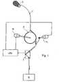
- Fig. 1diagrammatically shows a knitting line in which a yarn F is wound on a rotating, yarn-winding drum D of a positive yarn feeder YF, which draws the yarn from a reel R and feeds it to a general knitting machine M.
- the speed of rotation of drum Dis conventionally managed by a control loop provided with a tension sensor S, which senses the tension of the yarn downstream of feeder YF and sends a corresponding signal to a control unit CPU.
- the latteris conventionally programmed to control the speed of feeder YF such as to maintain the feeding tension of yarn F substantially constant, which tension depends on the difference between the speed of rotation of drum D and the drawing speed of dowstream machine M.
- Feeder YFis provided with a tension-limiting device TL adapted to operate during the transients at the start of the feeding process, in order to prevent tension peaks due to the relatively low quickness of movement of the yarn-winding drum with respect to the high quickness of drawing of the downstream machine.
- Feeder YFcomprises a housing 12 on which motorized drum D is supported.
- the operative parameters of feeder YFare set using a push-button panel 16 provided with a display 18.
- the yarn unwinding from drum Dpasses through tension sensor S, which is incorporated within feeder YF.
- Tension-limiting device TLcomprises a flat spiral spring 24, whose outer end projects into a guiding member shaped as an arm 26 terminating with a hook-shaped end 28 which engages yarn F unwinding from drum D.
- the inner end 32 of spring 24is coaxially attached to an output shaft 34 of a ratio-motor 36 fixed to housing 12 of the feeder.
- Ratio-motor 36is driven by a stepping motor SM which is operatively connected to control unit CPU (see also Fig. 1 ).
- Control unit CPUis programmed to control the angular position of ratio-motor 36 in such a way as to adjust the preload of spring 24 depending on the feeding tension, which is set by the operator on the basis of various parameters such as the yarn type, the process, the downstream machine type, and the like.
- Ratio-motor 36comprises a driving gear 38, which is attached to the driving shaft of motor SM and meshes with a driven gear 40, to which output shaft 34 of the ratio-motor is connected.
- Driven gear 40has a projection 42 arranged to abut against an abutment 44 in both the direction of rotation, thereby substantially limiting the rotational stroke of the gear to one revolution.
- Spring 24is attached to driven gear 40 at a position such that, when projection 42 abuts on one side of abutment 44, the spring is substantially released ( Fig. 4 ) and arm 26 abuts on stop 30.
- Each step of rotation of motor SMcorresponds to a predetermined preload on the spring, up to a condition of maximum preload in which projection 42 abuts on the opposite side of abutment 44 ( Fig. 5 ).
- the relation between the preload on the spring and the deriving tensionsmay be experimentally measured in a conventional way in the field.
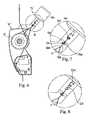
- Figs. 6-8show an example not part of the invention of tension-limiting device TL', which is based on the same principles described above and is appliable to the same type of positive yarn feeder YF'.
- tension-limiting device TL'comprises a spiral spring 124 having one end which projects into a guiding member 126 which passes through a slot 150 formed on a transverse wall 130 and terminates with a hook-shaped end 128 engaging the yarn unwinding from drum D'.
- guiding member 126Upstream of hook-shaped end 128, guiding member 126 has a turn 131 adapted to abut against wall 130, which, accordingly, defines a stop for guiding member 126.
- the yarn unwinding from drum D'is deviated from its natural path, thereby forming a reserve which will be temporarily releasable during the starting transients of the feeding process.
- guiding member 126subject to the tension of the yarn, will be pulled outwards in contrast to the elastic return action applied by spring 124, thereby releasing the yarn forming the reserve.
- the yarnis subject to a tension depending on the preload on spring 124.
- spring 124is connected to an operating rod 134 of a linear actuator 136 connected operatively to control unit CPU.
- the latterlikewise the previous embodiment, is programmed to control the position of actuator 136 such as to automatically adjust the preload on spring 124 on the basis of the feeding tension.
- the positions of the various parts of the deviceare designed such that, with the actuator at its outer stop position, the spring is substantially released ( Figs. 6, 7 ).
- Each inner position of the actuatorcorresponds to a predetermined preload on the spring, up to the condition of maximum preload in which the actuator reaches the opposite stop position ( Fig. 8 ).
- the relation between the preload on the spring and the deriving tensionsmay be experimentally measured in a conventional way in the field.
- the stepping motorcould be replaced by other motor means, e.g., a brushless motor with feedback control, by techniques falling within the normal knowledge of the person skilled in the art.
- the linear actuatorcould also be replaced by other driving means having a linear stoke, such as a stepping/brushless motor coupled with a screw gearing.
- the guiding memberis made enbloc from the spring, of course it could be formed as a separate part.
- the shape and the size of the guiding membercan be extensively varied, any mechanical member being suitable as far as it is capable of slidably engaging the yarn unwinding from the drum and deviating its path in contrast to the tension of the yarn.
- the spiral springcan be replaced by any other technically equivalent, elastic member acting by traction, such as a rubber rope, and the like.
Landscapes
- Engineering & Computer Science (AREA)
- Textile Engineering (AREA)
- Tension Adjustment In Filamentary Materials (AREA)
- Knitting Machines (AREA)
- Looms (AREA)
Description
- The present invention relates to a positive yarn feeder for textile machines, of the type provided with a tension-limiting device for preventing tension peaks on the yarn.
- As known, in a general knitting using knitting machines and the like, the yarn may be fed to the downstream machine by a so-called "positive" yarn feeder. With this type of feeder, the yarn is wound on a motorized, yarn-winding drum, which draws the yarn from a reel and feeds it to the dowstream machine.
- It is desirable to measure and control the yarn tension along the knitting line in order to maintain it substantially constant and to prevent surging of tension, which may cause defects in the finished clothes and affect the production yield. Since this tension depends on the difference between the speed of rotation of the drum of the feeder and the drawing speed of the downstream machine, it is conventionally controlled by modulating the speed of rotation of the drum on the basis of a signal received from a tension sensor arranged downstream of the feeder, by means of a tension control loop. In other words, the variation of tension to be applied is converted into a difference between the yarn-feeding speed and the yam-drawing speed which is set on the downstream machine.
- Although the above system effectively operates in steady state, a drawback well known to the person skilled in the art occurs in the transient state at the start of the feeding process, when the yarn is subjected to tension peaks due to the relatively low quickness of movement of the yarn-winding drum with respect to the high quickness of drawing of the downstream machine.
- In order to overcome the above drawback, it is known, e.g., from
EP 0 256 519 , to provide the yarn feeder with a tension-limiting device capable of storing a reserve between the feeder and the downstream machine, which reserve is releasable during the starting transients in order to prevent the above tension peaks. In the embodiment ofEP 0 256 519 , a reserve is formed by deviating the yarn from its natural path between two stationary eyelets, by means of a rigid bar connected to the driving shaft of a motor. At rest, as well as in steady state, the bar is positioed in such a way as to deviate the yarn from its natural path. In the transient state at the start of the feeding process, the bar is rotated in such a way as to temporarily release the yarn. - The above tension-limiting device requires very accurate control of the movement of the bar and, therefore, introduces considerable complications in the control system of the feeder, with consequent rise in costs.
- A simpler system, which is very effective in reducing the tension peaks, is described in
US 3,962,891 , wherein, likewise the previous system, a reserve is formed by deviating the yarn from its natural path between two stationary eyelets. Unlike the previous system, however, inUS 3,962,891 the yarn is not deviated "actively" by a rigid bar connected to a controlled motor, but "passively" by an arm integral with a flat spiral spring which is loaded to a predetermined tension. During the starting transients, the arm bends in contrast to the returning action of the spring and the reserve is released. At this stage, the yarn is maintained at a desired level of tension depending on the preload on the spring. - The above system is effective and easy to put into practice, but it has the drawback that, when it is desired to adjust the operative tension in relation to any variations of the feeding tension - which, as known, are managed in a fully automated way on the basis of the characteristics of the yarn, of the type of processing, of the type of dowstream machine, etc. - the load of the spring must be manually adjusted, with consequent reduction of the degree of automation of the line.
- Document
EP 2262940 A1 in prior art under Article 54 (3) EPC. - Hence, it is a main object of the present invention to provide a positive yarn feeder provided with a tension-limiting device which is capable of adjusting its operative tension in a fully automated way on the basis of the parameters which are set on the knitting line.
- The above object and other advantages, which will better appear below, are achieved by a yarn feeder having the features recited in claim 1, while the dependent claims state other advantageous, though secondary features of the invention.
- The invention will be now described in more detail with reference to a preferred, non-exclusive embodiment shown by way of non-limiting example in the attached drawings, wherein:
Fig. 1 diagrammatically shows a knitting line having a positive yarn feeder installed thereon provided with a tension-limiting device according to the invention;Fig. 2 is a detailed front view of the positive yarn feeder with tension-limiting device according to the invention;Fig. 3 is a view similar toFig. 2 but showing the tension-limiting device in a different operative configuration;Fig. 4 is a broken-away view to an enlarged scale of the tension-limiting device ofFig. 2 ;Fig. 5 is a view similar toFig. 4 but showing the tension-limiting device in a different operative configuration;Fig. 6 is a detailed front view of the positive yarn feeder with tension-limiting device according to an example not part of the invention of the invention;Fig. 7 shows a detail ofFig. 6 to an enlarged scale;Fig. 8 shows the detail ofFig. 7 in a different operative configuration.Fig. 1 diagrammatically shows a knitting line in which a yarn F is wound on a rotating, yarn-winding drum D of a positive yarn feeder YF, which draws the yarn from a reel R and feeds it to a general knitting machine M.- The speed of rotation of drum D is conventionally managed by a control loop provided with a tension sensor S, which senses the tension of the yarn downstream of feeder YF and sends a corresponding signal to a control unit CPU. The latter is conventionally programmed to control the speed of feeder YF such as to maintain the feeding tension of yarn F substantially constant, which tension depends on the difference between the speed of rotation of drum D and the drawing speed of dowstream machine M.
- Feeder YF is provided with a tension-limiting device TL adapted to operate during the transients at the start of the feeding process, in order to prevent tension peaks due to the relatively low quickness of movement of the yarn-winding drum with respect to the high quickness of drawing of the downstream machine.
- Positive yarn feeder YF with tension-limiting device TL is shown in detail in
Fig. 2 . Feeder YF comprises ahousing 12 on which motorized drum D is supported. The operative parameters of feeder YF are set using a push-button panel 16 provided with adisplay 18. The yarn unwinding from drum D passes through tension sensor S, which is incorporated within feeder YF. - Tension-limiting device TL comprises a flat
spiral spring 24, whose outer end projects into a guiding member shaped as anarm 26 terminating with a hook-shaped end 28 which engages yarn F unwinding from drum D. - At rest,
spring 24biases arm 26 against astop 30, at a position such that yarn F unwinding from drum D is deviated from its natural path, thereby forming a reserve which will be temporarily releasable during the above-mentioned starting transients.Arm 26, subject to the tension of the yarn, may rotate in contrast to the elastic return action ofspring 24, thereby releasing the reserve. At this stage, the yarn is subject to an operative tension depending on the preload onspring 24. - According to this invention, with particular reference to
Figs. 4, 5 , theinner end 32 ofspring 24 is coaxially attached to anoutput shaft 34 of a ratio-motor 36 fixed tohousing 12 of the feeder. Ratio-motor 36 is driven by a stepping motor SM which is operatively connected to control unit CPU (see alsoFig. 1 ). Control unit CPU is programmed to control the angular position of ratio-motor 36 in such a way as to adjust the preload ofspring 24 depending on the feeding tension, which is set by the operator on the basis of various parameters such as the yarn type, the process, the downstream machine type, and the like. Figs. 4 and 5 show the interior of ratio-motor 36 in detail, in two different operative configurations. Ratio-motor 36 comprises adriving gear 38, which is attached to the driving shaft of motor SM and meshes with a drivengear 40, to whichoutput shaft 34 of the ratio-motor is connected.Driven gear 40 has aprojection 42 arranged to abut against anabutment 44 in both the direction of rotation, thereby substantially limiting the rotational stroke of the gear to one revolution.Spring 24 is attached to drivengear 40 at a position such that, whenprojection 42 abuts on one side ofabutment 44, the spring is substantially released (Fig. 4 ) andarm 26 abuts onstop 30. Each step of rotation of motor SM corresponds to a predetermined preload on the spring, up to a condition of maximum preload in whichprojection 42 abuts on the opposite side of abutment 44 (Fig. 5 ). Of course, the relation between the preload on the spring and the deriving tensions may be experimentally measured in a conventional way in the field.Figs. 6-8 show an example not part of the invention of tension-limiting device TL', which is based on the same principles described above and is appliable to the same type of positive yarn feeder YF'.- Having particular reference to
Fig. 7 , tension-limiting device TL' comprises aspiral spring 124 having one end which projects into a guidingmember 126 which passes through aslot 150 formed on atransverse wall 130 and terminates with a hook-shaped end 128 engaging the yarn unwinding from drum D'. Upstream of hook-shaped end 128, guidingmember 126 has aturn 131 adapted to abut againstwall 130, which, accordingly, defines a stop for guidingmember 126. - Similarly to the previous embodiment, the yarn unwinding from drum D' is deviated from its natural path, thereby forming a reserve which will be temporarily releasable during the starting transients of the feeding process. In particular, guiding
member 126, subject to the tension of the yarn, will be pulled outwards in contrast to the elastic return action applied byspring 124, thereby releasing the yarn forming the reserve. At this stage, the yarn is subject to a tension depending on the preload onspring 124. - The opposite end of
spring 124 is connected to anoperating rod 134 of alinear actuator 136 connected operatively to control unit CPU. The latter, likewise the previous embodiment, is programmed to control the position ofactuator 136 such as to automatically adjust the preload onspring 124 on the basis of the feeding tension. - The positions of the various parts of the device are designed such that, with the actuator at its outer stop position, the spring is substantially released (
Figs. 6, 7 ). Each inner position of the actuator corresponds to a predetermined preload on the spring, up to the condition of maximum preload in which the actuator reaches the opposite stop position (Fig. 8 ). Also in this case, the relation between the preload on the spring and the deriving tensions may be experimentally measured in a conventional way in the field. - A preferred embodiment of the invention has been described herein, but of course many changes may be made by a person skilled in the art within the scope of the claims. For example, in the embodiment the stepping motor could be replaced by other motor means, e.g., a brushless motor with feedback control, by techniques falling within the normal knowledge of the person skilled in the art. Similarly, in the example not being part of the invention the linear actuator could also be replaced by other driving means having a linear stoke, such as a stepping/brushless motor coupled with a screw gearing. Although in the above-described embodiments the guiding member is made enbloc from the spring, of course it could be formed as a separate part. Moreover, the shape and the size of the guiding member can be extensively varied, any mechanical member being suitable as far as it is capable of slidably engaging the yarn unwinding from the drum and deviating its path in contrast to the tension of the yarn. Of course, in the example not being part of the invention the spiral spring can be replaced by any other technically equivalent, elastic member acting by traction, such as a rubber rope, and the like.
Claims (4)
- A positive yam feeder, comprising:- a motorized yarn-winding drum (D) adapted to have a plurality of loops of yam (F) wound thereon and driven to rotate for drawing said yam (F) from a reel (R) and feeding it to a general downstream machine (M), and- a movable guiding member (26), which is biased to slidably engage the yam (F) unwinding from the drum (D) and to deviate its path by a spring (24) acting in contrast to the tension of the yarn (F), thereby generating a reserve releasable in response to tension peaks on the yam,wherein the stroke of said guiding member (26) is limited by a stop (30) defining a position of maximum deviation of the yam (F), and said spring (24) has one end operatively connected to the guiding member (26) and an opposite end connected to driving means (36, 136) operable for applying a load to the spring (24), with the guiding member (26) abutting against said stop (30), said driving means (36) being of a rotating type and comprising a stepping motor controlled by a control unit (CPU) which is programmed to adjust said load as a function of a desired feeding tension, and said spring being a flat spiral spring (24) having an inner end (32) coaxially attached to the output shaft (34) of said rotating driving means (36), and an outer end from which said guiding member projects into the shape of an arm (26).
- The positive yam feeder of claim 1,characterized in that said rotating driving means comprise a ratio-motor (36) driven by said stepping motor (SM).
- The positive yarn feeder of any of claim 1 or 2,characterized in that the stroke of said rotating driving means (36) is delimited by an abutment (44) defining a released position of the spring (24).
- The positive yam feeder of any of claims 1-3,characterized in that said arm (26) is made enbloc with said spring (24).
Priority Applications (5)
| Application Number | Priority Date | Filing Date | Title |
|---|---|---|---|
| EP08425821.9AEP2204481B1 (en) | 2008-12-30 | 2008-12-30 | Positive yarn feeder with tension limiter |
| EP12004586.9AEP2503039B1 (en) | 2008-12-30 | 2008-12-30 | Positive yarn feeder with tension limiter |
| US12/654,407US8356765B2 (en) | 2008-12-30 | 2009-12-18 | Positive yarn feeder with tension limiter |
| CN200910266803.0ACN101768827B (en) | 2008-12-30 | 2009-12-29 | Positive yarn feeder with tension limiter |
| US13/694,166US8584981B2 (en) | 2008-12-30 | 2012-11-02 | Positive yarn feeder with tension limiter |
Applications Claiming Priority (1)
| Application Number | Priority Date | Filing Date | Title |
|---|---|---|---|
| EP08425821.9AEP2204481B1 (en) | 2008-12-30 | 2008-12-30 | Positive yarn feeder with tension limiter |
Related Child Applications (2)
| Application Number | Title | Priority Date | Filing Date |
|---|---|---|---|
| EP12004586.9ADivisionEP2503039B1 (en) | 2008-12-30 | 2008-12-30 | Positive yarn feeder with tension limiter |
| EP12004586.9Division-Into | 2012-06-19 |
Publications (2)
| Publication Number | Publication Date |
|---|---|
| EP2204481A1 EP2204481A1 (en) | 2010-07-07 |
| EP2204481B1true EP2204481B1 (en) | 2013-07-10 |
Family
ID=40834473
Family Applications (2)
| Application Number | Title | Priority Date | Filing Date |
|---|---|---|---|
| EP12004586.9AActiveEP2503039B1 (en) | 2008-12-30 | 2008-12-30 | Positive yarn feeder with tension limiter |
| EP08425821.9AActiveEP2204481B1 (en) | 2008-12-30 | 2008-12-30 | Positive yarn feeder with tension limiter |
Family Applications Before (1)
| Application Number | Title | Priority Date | Filing Date |
|---|---|---|---|
| EP12004586.9AActiveEP2503039B1 (en) | 2008-12-30 | 2008-12-30 | Positive yarn feeder with tension limiter |
Country Status (3)
| Country | Link |
|---|---|
| US (2) | US8356765B2 (en) |
| EP (2) | EP2503039B1 (en) |
| CN (1) | CN101768827B (en) |
Families Citing this family (14)
| Publication number | Priority date | Publication date | Assignee | Title |
|---|---|---|---|---|
| CN101988233B (en)* | 2010-09-03 | 2012-09-26 | 孙嘉良 | Single-yarn control device of computer type Jacquard warp-knitting machine |
| CN101974823B (en)* | 2010-11-12 | 2011-09-21 | 中材科技股份有限公司 | Compensated mechanical yarn tension control device |
| EP2623653A1 (en)* | 2012-02-04 | 2013-08-07 | Karl Mayer Textilmaschinenfabrik GmbH | Position bar assembly for a knitwear machine |
| ITTO20120435A1 (en)* | 2012-05-17 | 2013-11-18 | Lgl Electronics Spa | YARN FEEDER WITH ROTATING DRUM FOR TEXTILE MACHINES. |
| ITTO20130875A1 (en)* | 2013-10-29 | 2015-04-30 | Lgl Electronics Spa | POSITIVE YARN FEEDER WITH CONTROL OF POWER SUPPLY VOLTAGE. |
| CN103668769B (en)* | 2013-12-26 | 2015-04-29 | 宁波裕人数控科技有限公司 | Yarn measuring device for circular knitting machine |
| ITUA20162665A1 (en)* | 2016-04-18 | 2017-10-18 | Giovanni Corsani | YARN FEEDER FOR TEXTILE MACHINES WITH AUTOMATIC VOLTAGE REGULATION |
| ITUA20164460A1 (en)* | 2016-06-17 | 2017-12-17 | Lgl Electronics Spa | YARN FEEDER WITH REEL ROLL-MOTORIZED WIRE |
| IT201800002452A1 (en)* | 2018-02-06 | 2019-08-06 | Btsr Int Spa | METHOD, IMPROVED YARN FEEDING SYSTEM AND DEVICE TO OPTIMIZE YARN FEEDING TO A TEXTILE MACHINE OPERATING WITH HIGH DISCONTINUITY OR WITH AN ALTERNATING MOTION |
| DE102018115631A1 (en)* | 2018-06-28 | 2020-01-02 | Memminger-Iro Gmbh | Thread delivery device and system with a thread delivery device |
| CN108978016A (en)* | 2018-09-17 | 2018-12-11 | 伊婕 | A kind of knitting machine yarn-feeding device |
| CN110499574B (en)* | 2019-08-05 | 2021-04-02 | 福建屹立智能化科技有限公司 | Electronic transverse moving controller and control method |
| CN114229610B (en)* | 2021-12-21 | 2022-09-30 | 长飞光纤光缆股份有限公司 | Optical fiber on-line capturing and traction device |
| US12276052B2 (en) | 2021-12-22 | 2025-04-15 | Nike, Inc. | Tensioning device |
Family Cites Families (11)
| Publication number | Priority date | Publication date | Assignee | Title |
|---|---|---|---|---|
| FR2264904B1 (en) | 1974-03-21 | 1977-08-19 | Inst Textile De France | |
| DE3341042A1 (en)* | 1983-07-25 | 1985-02-07 | Textilma Ag, Hergiswil | DEVICE FOR FEEDING AND CONTROLLING A THREAD FOR A TEXTILE MACHINE, IN PARTICULAR A WEAVING MACHINE |
| DE3627731C1 (en)* | 1986-08-16 | 1988-03-31 | Gustav Memminger | Thread delivery device with electronic thread tension control |
| IT1203379B (en)* | 1987-03-19 | 1989-02-15 | Savio Spa | DEVICE AND RELATED PROCEDURE FOR ACCUMULATING AND RETURNING INTERMITTENT WIRE IN THE WINDING FI ROCKS SUPPLIED WITH CONSTANT SPEED WIRE |
| IT1203385B (en)* | 1987-03-19 | 1989-02-15 | Savio Spa | DEVICE AND RELATED PROCEDURE FOR ACUMMULATING AND RETURNING INTERMITTENT WIRE IN THE WINDING OF CONICAL SPOOLS FEED WITH CONSTANT SPEED WIRE |
| DE10113184B4 (en)* | 2001-02-26 | 2006-04-20 | Memminger-Iro Gmbh | Knitting machine thread feed unit has a lever spring-operated moving end-stop |
| ITMI20020945A1 (en)* | 2002-05-03 | 2003-11-03 | Tiziano Barea | METHOD AND DEVICE FOR THE CONSTANT VOLTAGE SUPPLY AND RECOVERY OF A YARN SUPPLIED TO A TEXTILE MACHINE |
| ITFI20040113A1 (en)* | 2004-05-14 | 2004-08-13 | Giovanni Corsani | WIRE FEEDER DEVICE |
| JP4336303B2 (en)* | 2004-12-16 | 2009-09-30 | 株式会社島精機製作所 | Yarn feeder for flat knitting machine |
| ITFI20060335A1 (en)* | 2006-12-22 | 2008-06-23 | Giovanni Corsani | A FEEDER AND WIRE RETRACTOR DEVICE FOR TEXTILE MACHINES |
| ITMI20080410A1 (en)* | 2008-03-11 | 2009-09-12 | Btsr Int Spa | DEVICE AND METHOD FOR CONSTANT VOLTAGE SUPPLY OF YARNS POWERED IN A DISCONTINUOUS WAY |
- 2008
- 2008-12-30EPEP12004586.9Apatent/EP2503039B1/enactiveActive
- 2008-12-30EPEP08425821.9Apatent/EP2204481B1/enactiveActive
- 2009
- 2009-12-18USUS12/654,407patent/US8356765B2/ennot_activeExpired - Fee Related
- 2009-12-29CNCN200910266803.0Apatent/CN101768827B/enactiveActive
- 2012
- 2012-11-02USUS13/694,166patent/US8584981B2/enactiveActive
Also Published As
| Publication number | Publication date |
|---|---|
| US20130068872A1 (en) | 2013-03-21 |
| EP2204481A1 (en) | 2010-07-07 |
| US20100162773A1 (en) | 2010-07-01 |
| EP2503039A1 (en) | 2012-09-26 |
| CN101768827A (en) | 2010-07-07 |
| EP2503039B1 (en) | 2013-06-26 |
| US8584981B2 (en) | 2013-11-19 |
| CN101768827B (en) | 2014-03-12 |
| US8356765B2 (en) | 2013-01-22 |
Similar Documents
| Publication | Publication Date | Title |
|---|---|---|
| EP2204481B1 (en) | Positive yarn feeder with tension limiter | |
| RU2303089C2 (en) | Method for feeding and receiving of thread at constant tension in textile machine and apparatus for performing the same | |
| KR100302035B1 (en) | Yarn feeding device and method for using elastic yarn, knitted products using the same | |
| EP1991726B1 (en) | Improved device for feeding thread or yarn to a textile machine and a method for implementing the feed | |
| US9181064B2 (en) | Method and device for feeding a yarn or thread to a processing machine with constant tension and velocity | |
| EP2642004B1 (en) | Yarn-feeding/recovering method for textile machines, and apparatus for carrying out such method | |
| EP3257984B1 (en) | Yarn feeder with motorized yarn winding spool | |
| RU2648192C2 (en) | Yarn recovery device and yarn feed system comprising said device | |
| EP2829647B1 (en) | Yarn feeder provided with a weft-winding drum and with a feedback-controlled, weft-braking device | |
| CN104755401A (en) | Method and system for feeding a thread to a textile machine, at a constant tension and preset draw, as a function of the operating step of the latter | |
| EP3481981B1 (en) | Zero-twist yarn feeding device | |
| US6233979B1 (en) | Circular knitting machine for production of knitwear with selectively different characteristics and method of adjusting it | |
| EP3575253B1 (en) | Yarn feeder with motorized yarn-winding spool and rewinding system | |
| JP5182210B2 (en) | Method for detecting the diameter of a warp beam in a loom | |
| JP7181947B2 (en) | Method, improved yarn feeding system and apparatus for optimal yarn feeding to textile machines operating in highly discontinuous or staggered motion | |
| KR101520525B1 (en) | A process for regulating a size of knitted articles under production in circular knitting machines for knitwear or hosiery | |
| CN112209180B (en) | Method for feeding a plurality of yarns to a textile machine by means of a positive yarn feeder | |
| EP4431427A1 (en) | Positive yarn feeder, particularly for yarn feeding apparatuses for warping machines | |
| EP0933457B1 (en) | Device for feeding an elastically extendable yarn to hosiery knitting machines | |
| EP1598295B1 (en) | Device and method for forming a reserve of thread in textile machines such as for example spinning machines, texturing machines, mercerizing machines or suchlike | |
| US5353610A (en) | Device for controlling the feed of at least one yarn to a textile machine so as to compensate any pulling and excess tension exerted on the yarn | |
| JP2008303484A (en) | Method for regulating warp tension in loom |
Legal Events
| Date | Code | Title | Description |
|---|---|---|---|
| PUAI | Public reference made under article 153(3) epc to a published international application that has entered the european phase | Free format text:ORIGINAL CODE: 0009012 | |
| 17P | Request for examination filed | Effective date:20091029 | |
| AK | Designated contracting states | Kind code of ref document:A1 Designated state(s):AT BE BG CH CY CZ DE DK EE ES FI FR GB GR HR HU IE IS IT LI LT LU LV MC MT NL NO PL PT RO SE SI SK TR | |
| AX | Request for extension of the european patent | Extension state:AL BA MK RS | |
| AKX | Designation fees paid | Designated state(s):BE CH DE IT LI SE | |
| 17Q | First examination report despatched | Effective date:20110324 | |
| GRAP | Despatch of communication of intention to grant a patent | Free format text:ORIGINAL CODE: EPIDOSNIGR1 | |
| GRAS | Grant fee paid | Free format text:ORIGINAL CODE: EPIDOSNIGR3 | |
| GRAA | (expected) grant | Free format text:ORIGINAL CODE: 0009210 | |
| AK | Designated contracting states | Kind code of ref document:B1 Designated state(s):BE CH DE IT LI SE | |
| REG | Reference to a national code | Ref country code:CH Ref legal event code:EP | |
| REG | Reference to a national code | Ref country code:DE Ref legal event code:R096 Ref document number:602008025890 Country of ref document:DE Effective date:20130905 | |
| REG | Reference to a national code | Ref country code:SE Ref legal event code:TRGR | |
| PLBE | No opposition filed within time limit | Free format text:ORIGINAL CODE: 0009261 | |
| STAA | Information on the status of an ep patent application or granted ep patent | Free format text:STATUS: NO OPPOSITION FILED WITHIN TIME LIMIT | |
| 26N | No opposition filed | Effective date:20140411 | |
| REG | Reference to a national code | Ref country code:DE Ref legal event code:R097 Ref document number:602008025890 Country of ref document:DE Effective date:20140411 | |
| REG | Reference to a national code | Ref country code:CH Ref legal event code:PL | |
| PG25 | Lapsed in a contracting state [announced via postgrant information from national office to epo] | Ref country code:LI Free format text:LAPSE BECAUSE OF NON-PAYMENT OF DUE FEES Effective date:20131231 Ref country code:CH Free format text:LAPSE BECAUSE OF NON-PAYMENT OF DUE FEES Effective date:20131231 | |
| PGFP | Annual fee paid to national office [announced via postgrant information from national office to epo] | Ref country code:SE Payment date:20191126 Year of fee payment:12 | |
| REG | Reference to a national code | Ref country code:SE Ref legal event code:EUG | |
| PG25 | Lapsed in a contracting state [announced via postgrant information from national office to epo] | Ref country code:SE Free format text:LAPSE BECAUSE OF NON-PAYMENT OF DUE FEES Effective date:20201231 | |
| PGFP | Annual fee paid to national office [announced via postgrant information from national office to epo] | Ref country code:DE Payment date:20241218 Year of fee payment:17 | |
| PGFP | Annual fee paid to national office [announced via postgrant information from national office to epo] | Ref country code:BE Payment date:20241218 Year of fee payment:17 | |
| PGFP | Annual fee paid to national office [announced via postgrant information from national office to epo] | Ref country code:IT Payment date:20241120 Year of fee payment:17 |